Magdalena Puskarczyk, Radoslaw Jez, ABB Corporate Research ... · © ABB | Slide 2 The Design of a...
12
© ABB | Slide 1 The Design of a Multilayer Planar Transformer for a DC/DC Converter with a Resonant Inverter Magdalena Puskarczyk, Radoslaw Jez, ABB Corporate Research Center, Krakow, Poland September 2014
Transcript of Magdalena Puskarczyk, Radoslaw Jez, ABB Corporate Research ... · © ABB | Slide 2 The Design of a...

© ABB
| Slide 1
The Design of a Multilayer Planar Transformer for a DC/DC Converter with a Resonant Inverter
Magdalena Puskarczyk, Radoslaw Jez, ABB Corporate Research Center, Krakow, Poland
September 2014
© ABB
| Slide 2
The Design of a Multilayer Planar Transformer for a DC/DC Converter with a Resonant InverterAgenda
1. Introduction
2. Design requirements for the planar transformer
3. Simulation models description
4. Steps of the analysis
5. Constructed prototype and laboratory measurement
results
6. Conclusions
September 2014
© ABB
| Slide 3
Planar transformerIntroduction
Magnetic inductors and transformers are the fundamental
components for PE devices:
potential applications: high frequency filters, EMC chokes,
energy storages, galvanic insulations, etc.
requirements of mass production: stability of fundamental and
parasitic parameters (inductances, resistances, leakage
inductances, stray capacitances)
complicated design process of inductive elements due to the
complexity of a magnetic circuit and high frequency
interactions between windings
September 2014
© ABB
| Slide 4
Planar transformerDesign requirements
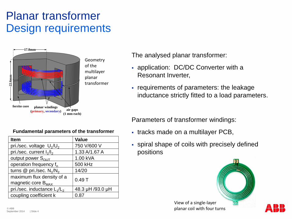
The analysed planar transformer:
application: DC/DC Converter with a
Resonant Inverter,
requirements of parameters: the leakage
inductance strictly fitted to a load parameters.
Parameters of transformer windings:
tracks made on a multilayer PCB,
spiral shape of coils with precisely defined
positions
September 2014
22
.6m
m
17.8mm
ferrite core planar windings
(primary, secondary)air gaps
(1 mm each)
Fundamental parameters of the transformer
Item Value
pri./sec. voltage U1/U2 750 V/600 V
pri./sec. current I1/I2 1.33 A/1.67 A
output power SOUT 1.00 kVA
operation frequency fn 500 kHz
turns @ pri./sec. N1/N2 14/20
maximum flux density of a
magnetic core BMAX
0.49 T
pri./sec. inductance L1/L2 48.3 μH /93.0 μH
coupling coefficient k 0.87
Geometryof the multilayer planar transformer
View of a single-layerplanar coil with four turns
© ABB
| Slide 5
Planar transformerSteps of the analysis
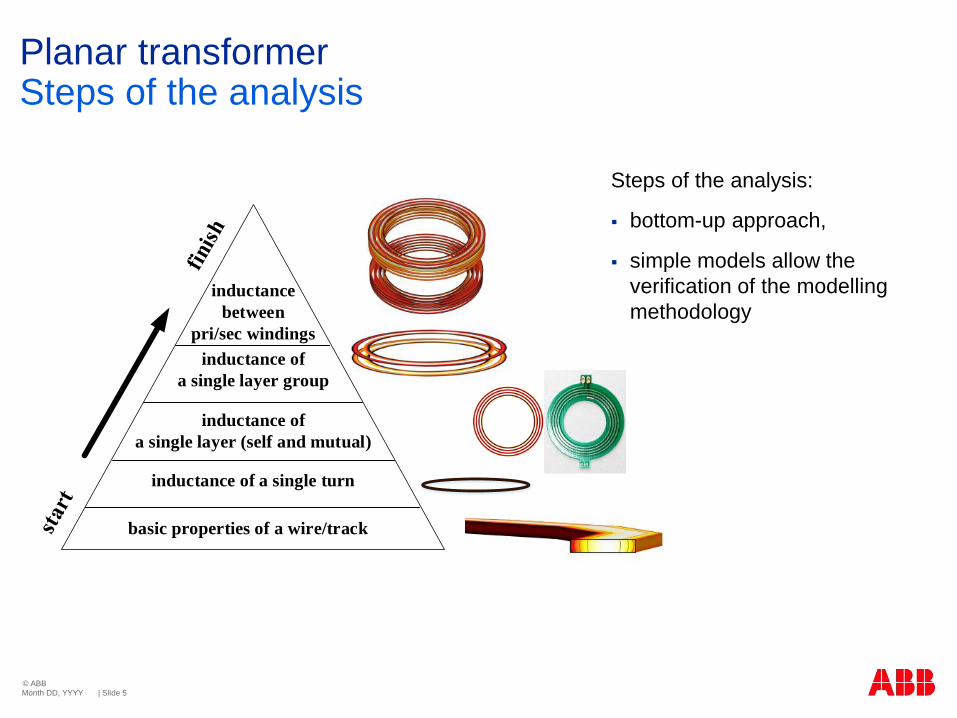
Steps of the analysis:
bottom-up approach,
simple models allow the
verification of the modelling
methodology
Month DD, YYYY
basic properties of a wire/track
inductance of a single turn
inductance of
a single layer (self and mutual)
inductance of
a single layer group
inductance
between
pri/sec windings
© ABB
| Slide 6
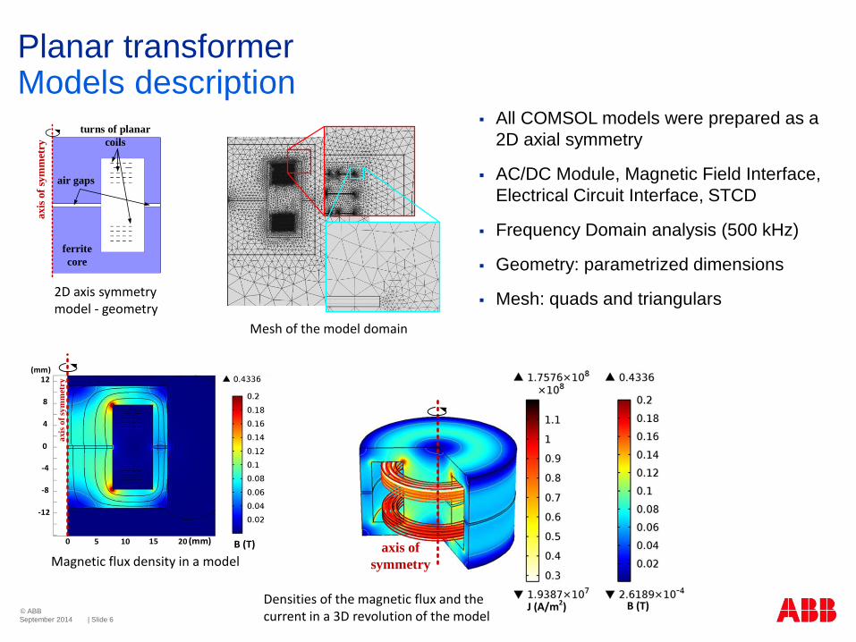
Planar transformerModels description
All COMSOL models were prepared as a
2D axial symmetry
AC/DC Module, Magnetic Field Interface,
Electrical Circuit Interface, STCD
Frequency Domain analysis (500 kHz)
Geometry: parametrized dimensions
Mesh: quads and triangulars
September 2014
ferrite
core
air gaps
turns of planar
coils
axis
of
sym
met
ry
B (T)J (A/m2)
axis of
symmetry
Densities of the magnetic flux and the current in a 3D revolution of the model
B (T)
axis
of
sym
met
ry
0
4
8
12
-12
-8
-4
0 5 10 15 20
(mm)
(mm)
2D axis symmetry model - geometry
Magnetic flux density in a model
Mesh of the model domain
© ABB
| Slide 7
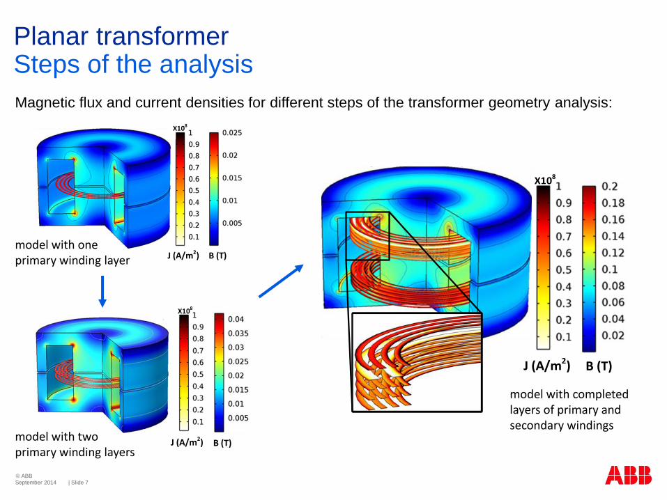
Planar transformerSteps of the analysis
September 2014
B (T)J (A/m2)
X108
B (T)
X108
J (A/m2)
Magnetic flux and current densities for different steps of the transformer geometry analysis:
B (T)J (A/m2)
X108
model with one primary winding layer
model with two primary winding layers
model with completed layers of primary and secondary windings
© ABB
| Slide 8
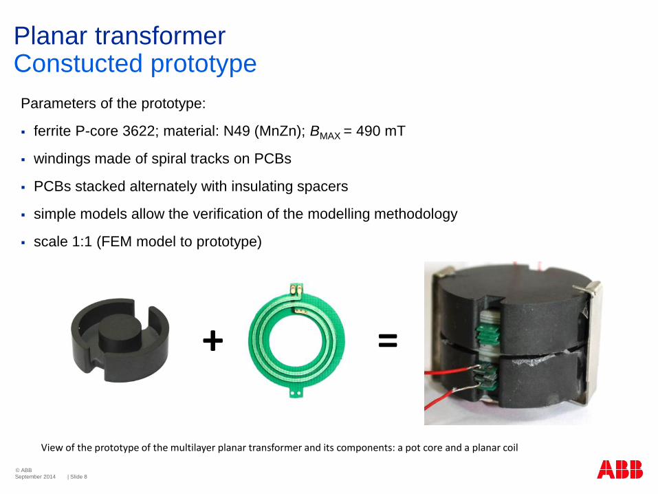
Planar transformerConstucted prototype
September 2014
+ =
View of the prototype of the multilayer planar transformer and its components: a pot core and a planar coil
Parameters of the prototype:
ferrite P-core 3622; material: N49 (MnZn); BMAX = 490 mT
windings made of spiral tracks on PCBs
PCBs stacked alternately with insulating spacers
simple models allow the verification of the modelling methodology
scale 1:1 (FEM model to prototype)
© ABB
| Slide 9
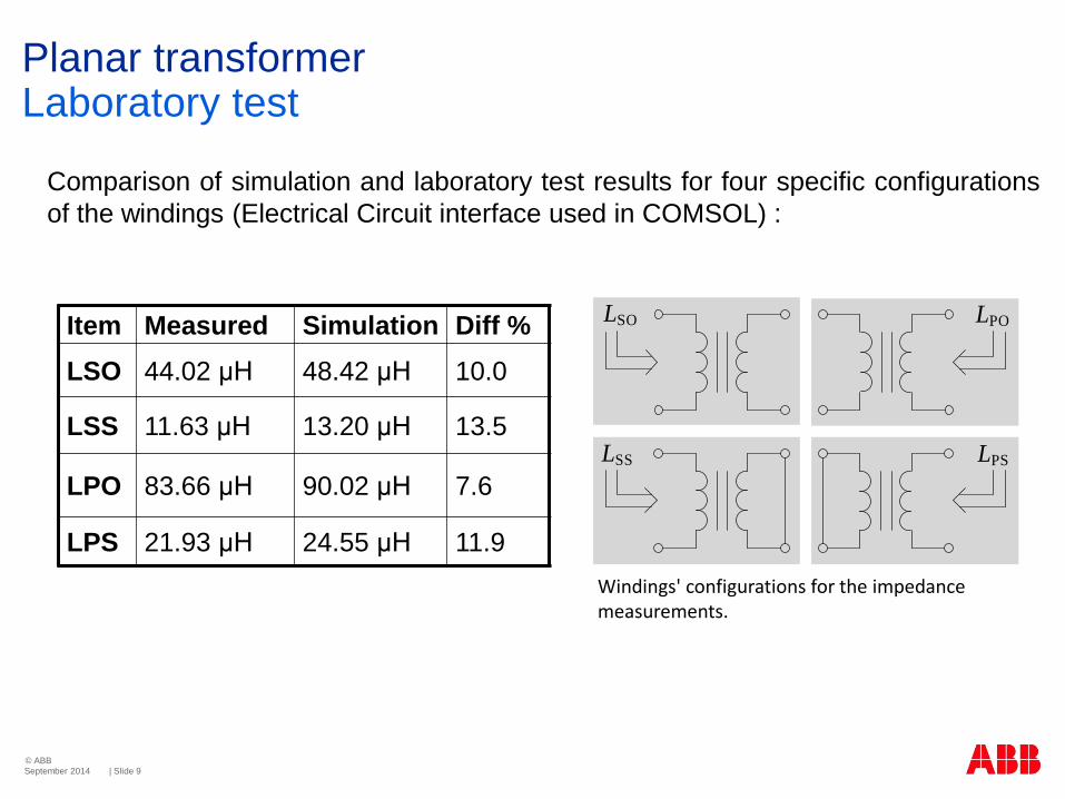
Planar transformerLaboratory test
Comparison of simulation and laboratory test results for four specific configurations
of the windings (Electrical Circuit interface used in COMSOL) :
September 2014
LPO
LPS
LSO
LSS
Item Measured Simulation Diff %
LSO 44.02 μH 48.42 μH 10.0
LSS 11.63 μH 13.20 μH 13.5
LPO 83.66 μH 90.02 μH 7.6
LPS 21.93 μH 24.55 μH 11.9
Windings' configurations for the impedance measurements.
© ABB
| Slide 10
Planar transformerConclusions
September 2014
The comparison of the FEM model results and laboratory
measurements shows the reliability of the COMSOL
calculations.
Changes of the transformer windings configurations impact the
magnetic field distribution in the core.
The FEM analyses allow to determine a magnetic core point of
operation and predict possible magnetic saturation,
The FEM calculation of a current density (with skin and proximity
effects) allows an optimal design of the cross-section of the
transformer windings.
© ABB
| Slide 11
Thank you very much for your attention!
I also would like to invite you to see the poster: 23
The Design of a Multilayer Planar Transformer for a DC/DC Converter with a Resonant Inverter
September 2014