Maestro Dual Technology Sensor Switch SPEC (369773) MaestroR Dual Technology (Dual Tech) Occupancy...
14
® SPECIFICATION SUBMITTAL Page Job Name: Job Number: Model Numbers: Dual Technology Occupancy Sensor Switch 369773c 1 04.09.14 Maestro® Sensor The MaestroR Dual Technology (Dual Tech) Occupancy Sensor Switch applies our exclusive XCT T Technology to the ultrasonic as well as the passive infrared technology in this sensor to create a product that can detect very fine motion, such as typing. This product also includes all of the great features found in the rest of the MaestroR sensor family, including: adaptive relay switching, smart ambient light detection, and simple button presses for changing settings. The MaestroR Dual Tech Occupancy Sensor Switch is available in single-circuit and dual-circuit versions. The single-circuit versions (MS-A102, MS-B102) can be used to meet many of the Title 20/24, ASHRAE 90.1, and IECC code requirements such as “automatic shutoff”. The dual-circuit versions (MS-A202, MS-B202) can be used to meet many of the Title 20/24, ASHRAE 90.1, and IECC code requirements such as “automatic shutoff” and “multi-level lighting control”. To find some examples of code-specific applications, visit www.lutron.com/energycodes Features • XCTT Technology for major, minor, fine, and very fine motion detection • 180° sensor field-of-view • Tamper-resistant PIR lens • Up to 900 ft 2 (81 m 2 ) major motion coverage and 400 ft 2 (36 m 2 ) minor motion coverage • Two Ambient Light Detect (ALD) options: - Learning ALD Mode: Uses adaptive algorithm. Sensor learns user’s preferred light level over time. - Fixed ALD mode: Four selectable light level thresholds: Hi, Med, Low, Min • Occupancy models (MS-A102-XX, MS-B102-XX, MS-A202-XX, MS-B202-XX) can be set to Auto-ON / Auto-OFF or Manual-ON / Auto-OFF per circuit • Dual-circuit models (MS-A202, MS-B202) meet Title 24 requirements for multi-level lighting control. • Single-circuit “Vacancy” models (MS-A102-V-XX, MS-B102-V-XX) available to meet Title 24 / Title 20 requirements for vacancy sensors. • Adjustable timeout for each circuit (1, 5, 15, or 30 minutes) • Sensitivity adjustment - PIR (Hi, Med, Low, Min) - Ultrasonic (Hi, Med, Low, Off) • Switches all lighting loads: incandescent, halogen, ELV, MLV, CFL, LED, magnetic fluorescent, electronic fluorescent • Switches fan loads at 120 V~ • MS-B102, MS-B102-V work with MaestroR accessory switches in multi-location applications • MS-A models DO NOT require neutral wiring, while the MS-B models DO require neutral wiring. Notes: • “XX” in the model number represents color/finish code. See Colors and Finishes at end of document. • Wallplate not included. MS-A102-XX (Occupancy model) MS-A102-V-XX (Vacancy model) MS-B102-XX (Occupancy model) MS-B102-V-XX (Vacancy model) Maestro® Dual Technology Sensor Switch MS-A202-XX (Occupancy model) MS-B202-XX (Occupancy model)
Transcript of Maestro Dual Technology Sensor Switch SPEC (369773) MaestroR Dual Technology (Dual Tech) Occupancy...

® Specif icat ion Submittal page
Job Name:
Job Number:
Model Numbers:
Dual Technology Occupancy Sensor Switch
369773c 1 04.09.14
Maestro® Sensor
The MaestroR Dual Technology (Dual Tech) Occupancy Sensor Switch applies our exclusive XCTT Technology to the ultrasonic as well as the passive infrared technology in this sensor to create a product that can detect very fine motion, such as typing. This product also includes all of the great features found in the rest of the MaestroR sensor family, including: adaptive relay switching, smart ambient light detection, and simple button presses for changing settings. The MaestroR Dual Tech Occupancy Sensor Switch is available in single-circuit and dual-circuit versions.
The single-circuit versions (MS-A102, MS-B102) can be used to meet many of the Title 20/24, ASHRAE 90.1, and IECC code requirements such as “automatic shutoff”. The dual-circuit versions (MS-A202, MS-B202) can be used to meet many of the Title 20/24, ASHRAE 90.1, and IECC code requirements such as “automatic shutoff” and “multi-level lighting control”. To find some examples of code-specific applications, visit www.lutron.com/energycodes
Features
• XCTT Technology for major, minor, fine, and very fine motion detection• 180° sensor field-of-view• Tamper-resistant PIR lens• Up to 900 ft2 (81 m2) major motion coverage and 400 ft2 (36 m2) minor
motion coverage• Two Ambient Light Detect (ALD) options: - Learning ALD Mode:
Uses adaptive algorithm. Sensor learns user’s preferred light level over time.
- Fixed ALD mode: Four selectable light level thresholds: Hi, Med, Low, Min
• Occupancy models (MS-A102-XX, MS-B102-XX, MS-A202-XX, MS-B202-XX) can be set to Auto-ON / Auto-OFF or Manual-ON / Auto-OFF per circuit
• Dual-circuit models (MS-A202, MS-B202) meet Title 24 requirements for multi-level lighting control.
• Single-circuit “Vacancy” models (MS-A102-V-XX, MS-B102-V-XX) available to meet Title 24 / Title 20 requirements for vacancy sensors.
• Adjustable timeout for each circuit (1, 5, 15, or 30 minutes)• Sensitivity adjustment - PIR (Hi, Med, Low, Min) - Ultrasonic (Hi, Med, Low, Off)• Switches all lighting loads: incandescent, halogen, ELV, MLV, CFL, LED,
magnetic fluorescent, electronic fluorescent• Switches fan loads at 120 V~
• MS-B102, MS-B102-V work with MaestroR accessory switches in multi-location applications
• MS-A models DO NOT require neutral wiring, while the MS-B models DO require neutral wiring.
Notes:• “XX” in the model number represents
color/finish code. See Colors and Finishes at end of document.
• Wallplate not included.
MS-A102-XX (Occupancy model)MS-A102-V-XX (Vacancy model)MS-B102-XX (Occupancy model)MS-B102-V-XX (Vacancy model)
Maestro® Dual Technology Sensor Switch
MS-A202-XX (Occupancy model)MS-B202-XX (Occupancy model)

® Specif icat ion Submittal page
Job Name:
Job Number:
Model Numbers:
Dual Technology Occupancy Sensor Switch
369773c 2 04.09.14
Maestro® Sensor
SpecificationsRegulatory Approvals
• ULR Listed to U.S. and Canadian safety requirements (applies only to MS-B102, MS-B102-V, MS-B202)
• NOM certified • Title 20 / 24 certified lighting control device – Complies with Title 20 and Title 24 section 110.9
Power / Load Control• 120 – 277 V~ 50 / 60 Hz
Key Design Features• Dual Sensing Technology• Switches all lighting loads• 6 A of lighting load per circuit at 120 – 277 V~
• 4.4 A (1/6 HP) of fan load per circuit at 120 V~
• Crush/tamper resistant lens• Smart Ambient Light Detection (ALD)• Fixed Ambient Light Detection• Adaptive zero-cross switching algorithm for
extended relay life (patent pending)• XCTT Technology for major, minor, fine, and very fine
motion detection• Programmable Circuit Swapping eliminates need
for rewiring to reassign circuits after installation of a dual-circuit product. (patent pending)
• Product ground current does not exceed 0.5 mA
Environment• Ambient operating temperature: 32 °F to 104 °F
(0 °C to 40 °C), 0% – 90% humidity, non-condensing. Indoor use only.
Warranty• 5-Year Limited Warranty. For additional Warranty
information, please visit www.lutron.com/TechnicalDocumentLibrary/Sensor_Warranty.pdf
Sensor DetectionLutronR Dual Tech sensors operate by triggering initial occupancy using PIR technology, and maintain occupancy using both ultrasonic and PIR technology.
Advanced FeaturesSwitching
• Adaptive zero-cross switching—maximizes relay life by switching at the point of minimum energy on the AC power curve (patent pending). Actively adapts to variations in relay timing.
Additional Information on Sensors• For single-circuit PIR MaestroR Occupancy
Sensor Switch models, please see LutronR P/N 369666
• For MaestroR Occupancy Sensor C•LR Dimmer models, please see LutronR P/N 369748
• For dual-circuit PIR Maestro Occupancy Sensor Switch, please see LutronR P/N 369758
• For more information, please see www.lutron.com/occvacsensors
• Lutron Technical Hotline: 1.800.523.9466.

® Specif icat ion Submittal page
Job Name:
Job Number:
Model Numbers:
Dual Technology Occupancy Sensor Switch
369773c 3 04.09.14
Maestro® Sensor
Custom SettingsDefault settings shown in bold
- Timeout• 30 min• 15 min• 5 min• 1 min
Mode - Sensor Modes Lights automatically turn off in all sensor modes• Occ -Occupancy mode (No ALD) 1,2,3
• Lrn - Occupancy with learning ALD mode• Fixd - Occupancy with fixed ALD mode• Vac - Vacancy mode (No ALD) 2,31 MS-A102-XX, MS-B102-XX default is Occ2 MS-A102-V-XX, MS-B102-V-XX is locked as Vac3 MS-A202-XX, MS-B202-XX defaults are: Circuit 1 - Occ, Circuit 2 - Vac
- Ultrasonic Sensitivity• High• Med• Low• Off
- Passive Infrared Sensitivity• High• Med• Low• Min
Additional Settings Fixed ALD Light Level• Hi• Med• Low *• Min* “Low” is the default setting for any sensor that is
set by the user to: Occupancy with fixed ALD mode
Off-While-Occupied• Enabled• Disabled
Walk-Thru Mode• Enabled• Disabled
Custom Settings - Details
Ambient Light Detection (ALD) modeLights turn on only when natural light in the room is below the set threshold.– Learning: The ambient light threshold adjusts to
the user’s preference via manual interaction with the sensor switch.
– Fixed: Choose a fixed ALD light level from four pre-set options: High, Medium, Low, and Minimum
Manual Off-While-Occupied OptionsENABLED (default setting)– When the sensor switch is manually turned off,
the sensor switch will not turn the lights back on automatically while the room is occupied.
– Once the room is vacated, the Auto-On feature returns to normal operation after the timeout period has expired.
– This may be the preference in conference rooms or classrooms while viewing presentations. This feature requires motions to keep the lights off.
DISABLED– When the sensor switch is manually turned off,
the Auto-On feature will return to normal operation after 25 seconds.
– This may be the preference in a restroom if the user always wants the lights to turn on upon entering and the lights to turn off when the room is vacant.
Walk-Thru ModeENABLED 1
– If motion is not detected within 3 minutes after initial occupancy, the lights will turn off after 3 minutes, instead of the current timeout.
– This setting may be the preference in commercial applications where personnel may briefly trigger sensors during non-working hours.
DISABLED (default setting)– When motion is detected, the lights will ALWAYS
remain on for the entire timeout duration, regardless of the duration of occupancy detection.
1 1 minute timeout would be overridden if walk-thru mode is also ENABLED

® Specif icat ion Submittal page
Job Name:
Job Number:
Model Numbers:
Dual Technology Occupancy Sensor Switch
369773c 4 04.09.14
Maestro® Sensor
Load Type and Capacity
ControlNeutral Connection Required
Vacancy Only
Number of Circuits
Voltage / Load Type / Maximum Load (Anywhere in Gang) 1
Minimum Load
3-Way with Mechanical Switch
Multi-Location with Accessory Switch
MS-A102 1
120 - 277 V~ Lighting 6 A 2
120 V~ Fan 4.4 A (1/6 HP) 3
0 A
MS-A102-V 1 0 A
MS-A202 2 0 A
MS-B102 1 0 A
MS-B102-V 1 0 A
MS-B202 2 0 A
1 Ratings shown are per circuit.2 Sensor Switch Load Type: Designed for use with permanently installed incandescent, halogen, MLV, ELV, CFL, LED, magnetic fluorescent, and electronic
fluorescent lighting loads.3 When controlling light and fan loads simultaneously on a single-circuit, maximum load capacity per circuit is 4.4 A at 120 V~.
Sensor Switch Placement• The sensor switch performs better with an unobstructed view of room occupants. • Hot objects and moving air currents can affect the performance of the sensor switch. The sensor switch performs
best when located 6 ft (1.8 m) or more away from hot objects or moving air currents.• The PIR performance depends on a temperature differential between the ambient room temperature and that of
room occupants. Warmer rooms may reduce the ability of the sensor switch to detect occupants.• The ultrasonic performance can be affected by air currents and moving objects. Consider the effects of fans,
HVAC vents, open windows, or moving objects when installing the sensor switch.• If the sensor sees a specific area that is not desired (e.g., hallway), Lutron offers a lens mask kit (LutronR P/N
50013614) that can be ordered through Tech Support (1.800.523.9466). Alternatively, selectively placing opaque tape (e.g., painter’s tape, electrical tape, masking tape) over certain parts of the lens can limit it’s field of vision to block undesired detection areas. Masking the lens may effect ALD performance, but DOES NOT block ultrasonic frequencies.
DefinitionsMajor motion: movement of a person entering or passing through an area.Minor motion: movement of a person occupying an area and engaging in small activities (e.g., reaching for a telephone, turning the pages of a book, opening a file folder, picking up a coffee cup).Fine Motion: movement of a person occupying an area and engaging in very small activities (e.g., reading a magazine).Very Fine Motion: movement of a person occupying an area and engaging in very small activities (e.g., typing on a keyboard).

® Specif icat ion Submittal page
Job Name:
Job Number:
Model Numbers:
Dual Technology Occupancy Sensor Switch
369773c 5 04.09.14
Maestro® Sensor
Sensor Switch Placement (continued)
0 10 ft (3 m)
15 ft (4.5 m)
20 ft (6 m)
25 ft (7.5 m)
30 ft (9 m)
5 ft (1.5 m)
5 ft (1.5 m)
0
10 ft (3 m)
10 ft (3 m)
15 ft (4.5 m)
15 ft (4.5 m)
5 ft (1.5 m)
NEMA WD7 Coverage
Major motion coverage: 900 ft2 (81 m2)
Minor motion coverage: 400 ft2 (36 m2)
0
10 ft (3 m)
10 ft (3 m)
20 ft (6 m)
20 ft (6 m)
30 ft (9 m)
30 ft (9 m)
10 ft (3 m)
20 ft (6 m)
30 ft (9 m)
4 ft (1.2 m)
0
Passive Infrared Beam Diagram (For Reference Only)
0
10 ft (3 m)
10 ft (3 m)
20 ft (6 m)
20 ft (6 m)
Test Room Dimensions: 37 ft x 38 ft (11.28 m x 11.6 m)Test Floor Surface Material: CarpetSensor Coverage Angle: 180 °Major motion coverage: Initial trigger motion detectionMinor motion coverage: Maintained motion detection
Ultrasonic Coverage (For Reference Only)
10 ft (3 m)
20 ft (6 m)
4 ft (1.2 m)
0
Ultrasonic Frequency: 40 kHz
® Specif icat ion Submittal page
Job Name:
Job Number:
Model Numbers:
Dual Technology Occupancy Sensor Switch
369773c 6 04.09.14
Maestro® Sensor
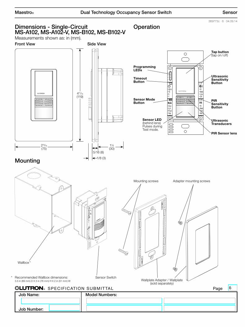
Dimensions - Single-Circuit MS-A102, MS-A102-V, MS-B102, MS-B102-V Measurements shown as: in (mm).Front View Side View
411⁄16
(119)
215⁄16
(75)11⁄8(30)
5/16 (8)
1/8 (3)Mounting
Wallbox *
Sensor SwitchWallplate Adapter / Wallplate
(sold separately)
Mounting screws Adapter mounting screws
Operation
m301551
OccLrnFixdVac
Mode
HiMedLowOff
HiMedLowMin
PIR
PIR Sensor lens
Tap button (tap on / off)
Ultrasonic Sensitivity Button
PIR Sensitivity Button
Sensor LED (behind lens) Pulses during Test mode.
Timeout Button
Sensor Mode Button
Programming LEDs
Ultrasonic Transducers
* Recommended Wallbox dimensions: 3.5 in (89 mm) D X 3 in (76 mm) H X 2 in (51 mm) W

® Specif icat ion Submittal page
Job Name:
Job Number:
Model Numbers:
Dual Technology Occupancy Sensor Switch
369773c 7 04.09.14
Maestro® Sensor
Dimensions - Dual-Circuit MS-A202, MS-B202 Measurements shown as: in (mm).
Front View Side View
411⁄16
(119)
215⁄16
(75)11⁄8(30)
5/16 (8)
Operation
m301551
OccLrnFixdVac
Mode
HiMedLowOff
HiMedLowMin
PIR
PIR Sensor lens
Top Tap button Controls Circuit 1(tap on / off)
Ultrasonic Sensitivity Button
PIR Sensitivity Button
Sensor LED (behind lens) Pulses during Test mode.
Bottom Tap button Controls Circuit 2(tap on / off)
Mounting
Sensor SwitchWallplate Adapter / Wallplate
(sold separately)
Mounting screws Adapter mounting screws
1/8 (3)
Timeout Button
Sensor Mode Button
Programming LEDs
Ultrasonic Transducers
Wallbox *
* Recommended Wallbox dimensions: 3.5 in (89 mm) D X 3 in (76 mm) H X 2 in (51 mm) W

® Specif icat ion Submittal page
Job Name:
Job Number:
Model Numbers:
Dual Technology Occupancy Sensor Switch
369773c 8 04.09.14
Maestro® Sensor
Wiring Diagrams - Single-Circuit
Wiring Diagram 1Single Pole Wiring - Single-Circuit (MS-A102, MS-A102-V)
m301551
HiMedLowOff
OccLrnFixdVac
ModeHiMedLowMin
PIR
Neutral
Black Red
Load
Green
Line/Hot
120–277 V~ 50 / 60 Hz
Wiring Diagram 2Single Pole Wiring - Single-Circuit (MS-B102, MS-B102-V)
m301551
HiMedLowOff
OccLrnFixdVac
ModeHiMedLowMin
PIR
Neutral
Black Black
LoadGreen
White
BlueLine/Hot
120–277 V~ 50 / 60 Hz
Ground
Ground
Green/Yellow
continued on next page...

® Specif icat ion Submittal page
Job Name:
Job Number:
Model Numbers:
Dual Technology Occupancy Sensor Switch
369773c 9 04.09.14
Maestro® Sensor
m301551
HiMedLowOff
OccLrnFixdVac
ModeHiMedLowMin
PIR
MS-B102 or MS-B102-V
Black
Blue
White
Ground
Black
Blue
Green
Ground
120 V~ 50 / 60 Hz
Black
Blue
Green
Ground
Line/Hot
Neutral
Load
BrassBrass
Green
Black
MA-AS or MSC-AS
MA-AS or MSC-AS
m301551
HiMedLowOff
OccLrnFixdVac
ModeHiMedLowMin
PIR
MS-B102 or MS-B102-V
Black
Blue
White
Ground
Black
Blue
Green
Ground
277 V~ 50 / 60 Hz
Black
Blue
Green
Ground
Line/Hot
Neutral
Load
RedRed
Green
Black
MA-AS-277 or MSC-AS-277
MA-AS-277 or MSC-AS-277
m301551
HiMedLowOff
OccLrnFixdVac
ModeHiMedLowMin
PIR
MS-B102 or MS-B102-V
Black
Blue
White
Ground
Black
Blue
Green
Ground
220/240 V~ 50 / 60 Hz
Black
Blue
Green
Ground
Line/Hot
Neutral
Load
RedRed
Green
Black
MA-AS-277 or MSC-AS-277
MA-AS-277 or MSC-AS-277
Note: Dual Tech Sensor Switch can be installed in any location. However, optimum performance of sensor may depend upon installation location, see sensor switch placement guidelines on page 4.
Note: Dual Tech Sensor Switch can be installed in any location. However, optimum performance of sensor may depend upon installation location, see sensor switch placement guidelines on page 4.
Note: Dual Tech Sensor Switch can be installed in any location. However, optimum performance of sensor may depend upon installation location, see sensor switch placement guidelines on page 4.
Wiring Diagram 3120 V~ Multi-Location Installation with MaestroR Accessory Switches (MS-B102, MSB102-V)
Wiring Diagram 5277 V~ Multi-Location Installation with MaestroR Accessory Switches (MS-B102, MSB102-V)
Wiring Diagram 4220/240 V~ Multi-Location Installation with MaestroR Accessory Switches (MS-B102, MSB102-V)

® Specif icat ion Submittal page
Job Name:
Job Number:
Model Numbers:
Dual Technology Occupancy Sensor Switch
369773c 10 04.09.14
Maestro® Sensor
m301551
OccLRNFixdVac
Mode
HiMedLowOff
HiMedLowMin
PIR
m301551
HiMedLowOff
OccLrnFixdVac
ModeHiMedLowMin
PIR
Black
Blue
Ground
MS-B102
Green
Ground
120–277 V~ 50 / 60 Hz
Line/Hot
Load
Standard Mechanical Switch
Black
Yellow Jumper wire (included)
Different color screw
Neutral
3-Way Installation For retrofit 3-way installations the mechanical switch needs to be rewired as shown in the diagram below after wiring the Dual Tech Sensor Switch. Otherwise the 3-way installation will not work as expected. Single Pole mechanical switches may also be used in a 3-way installation with MS-B102, MS-B102-V and MS-B202 models.
Wiring Diagrams - Single-Circuit (continued)
White
1. Connect Ground: Ensure the bare copper or green ground wire from the wallbox is connected to the green ground screw of the mechanical switch.
2. Tag circuit Common: Your 3-way mechanical switch should have three screw terminals, two of the same color, and one of a different color. Tag the wire that is connected to the screw terminal of a different color.
3. Identify the wire that matches the color of the wire you connected to the blue wire of the MaestroR Dual Technology Occupancy Sensor Switch. Connect this wire to one of the two terminals of the same color.
4. Combine the tagged wire, the remaining wire and yellow jumper wire (included) using a wire connector. Connect the other end of jumper wire to the different color screw.
Note: Dual Tech Sensor Switch can be installed in any location. However, optimum performance of sensor may depend upon installation location, see sensor switch placement guidelines on page 4.
Wiring Diagram 63-Way Installation - Single-Circuit (MS-B102, MS-B102-V)
m301551
OccLRNFixdVac
Mode
HiMedLowOff
HiMedLowMin
PIR
m301551
HiMedLowOff
OccLrnFixdVac
ModeHiMedLowMin
PIR
Traditional 3-Way Mechanical Switch Wiring
Ground
Traveler Traveler
Common
m301551
OccLRNFixdVac
Mode
HiMedLowOff
HiMedLowMin
PIR
m301551
HiMedLowOff
OccLrnFixdVac
ModeHiMedLowMin
PIR
Yellow Jumper wire (included)
Traveler (to Blue wire)
Tagged Wire (Common)
Traveler (to Black wire)
Ground
Different color screw
3-Way Mechanical Switch Wiring with Dual Tech Sensor Switch
Different color screw
Rewire to

® Specif icat ion Submittal page
Job Name:
Job Number:
Model Numbers:
Dual Technology Occupancy Sensor Switch
369773c 11 04.09.14
Maestro® Sensor
Wiring Diagrams - Dual-Circuit
Wiring must comply with NECR code for wiring multiple branch circuits. Where two or more branch circuits supply devices or equipment on the same yoke, a means to simultaneously disconnect the ungrounded conductors supplying those devices shall be provided at the point at which the branch circuits originate.
continued on next page...
m301551
OccLRNFixdVac
Mode
HiMedLowOff
HiMedLowMin
PIR
m301551
OccLrnFixdVac
Mode
HiMedLowOff
HiMedLowMin
PIR
Neutral
Black BlackLoad 1
Load 2
Green
Black-OrangeWhite
BlueLine/Hot
120–277 V~ 50 / 60 Hz
Ground
Black-Orange
Wiring Diagram 2Single Pole, Single Breaker Feed Wiring - Dual-Circuit (MS-B202)
m301551
OccLRNFixdVac
Mode
HiMedLowOff
HiMedLowMin
PIR
m301551
OccLrnFixdVac
Mode
HiMedLowOff
HiMedLowMin
PIR
Neutral
Black RedLoad 1
Load 2
Green
Black-Orange
Line/Hot
120–277 V~ 50 / 60 Hz
Ground
Green/YellowBlack-Orange
Wiring Diagram 1Single Pole, Single Breaker Feed Wiring - Dual-Circuit (MS-A202)
m301551
OccLRNFixdVac
Mode
HiMedLowOff
HiMedLowMin
PIR
m301551
OccLrnFixdVac
Mode
HiMedLowOff
HiMedLowMin
PIR
Neutral
Black BlackLoad 1
Load 2
Green
Black-Orange
White
Blue
Line/Hot
Line/Hot
120–277 V~ 50 / 60 Hz
Ground
Black-Orange
Wiring Diagram 4Single Pole, Two Breaker Feed Wiring: Dual-Circuit (MS-B202)
m301551
OccLRNFixdVac
Mode
HiMedLowOff
HiMedLowMin
PIR
m301551
OccLrnFixdVac
Mode
HiMedLowOff
HiMedLowMin
PIR
Neutral
Black RedLoad 1
Load 2Black-Orange
Line/Hot
Line/Hot
120–277 V~ 50 / 60 Hz
Black-Orange
Wiring Diagram 3Single Pole, Two Breaker Feed Wiring: Dual-Circuit (MS-A202)
GreenGround
Green/Yellow

® Specif icat ion Submittal page
Job Name:
Job Number:
Model Numbers:
Dual Technology Occupancy Sensor Switch
369773c 12 04.09.14
Maestro® Sensor
m301551
OccLRNFixdVac
Mode
HiMedLowOff
HiMedLowMin
PIR
m301551
OccLrnFixdVac
Mode
HiMedLowOff
HiMedLowMin
PIR
m301551
OccLRNFixdVac
Mode
HiMedLowOff
HiMedLowMin
PIR
m301551
OccLrnFixdVac
Mode
HiMedLowOff
HiMedLowMin
PIR
Black
Blue
Ground
MS-B202 1
Green
Ground
120–277 V~ 50 / 60 Hz
Line/Hot
Load 2
Standard Mechanical Switch 2,3
Black
Different color screw
Neutral
Black-Orange
Load 1
Black-OrangeWhite
Wiring Diagram 53-Way Installation, Single Breaker Feed Wiring: Dual-Circuit (MS-B202)NOTE: Do not use MaestroR accessory switches with MS-B202.
Wiring must comply with NECR code for wiring multiple branch circuits. Where two or more branch circuits supply devices or equipment on the same yoke, a means to simultaneously disconnect the ungrounded conductors supplying those devices shall be provided at the point at which the branch circuits originate.
Black
Blue
Ground
MS-B202 1
Green
Ground
120–277 V~ 50 / 60 Hz
Line/Hot
Load 2
Standard Mechanical Switch 2,3
Black
Yellow Jumper wire (included)
Yellow Jumper wire (included)
Different color screw
Neutral
Black-Orange
Load 1
Black-OrangeWhite
Line/Hot
Wiring Diagrams - Dual-Circuit (continued)
1 Dual Tech Sensor Switch can be installed in any location.2 Mechanical switch may be wired to either circuit, and will control both. Do NOT wire mechanical switch to both circuits.3 You may use no more than one mechanical switch with a dual-circuit Dual Tech Sensor Switch.
Wiring Diagram 63-Way Installation, Two Breaker Feed Wiring: Dual-Circuit (MS-B202)
Note: Do not use MaestroR accessory switches with MS-B202.
Note: Optimum performance of sensor may depend upon installation location, see sensor switch placement guidelines on page 4.
Note: Optimum performance of sensor may depend upon installation location, see sensor switch placement guidelines on page 4.

® Specif icat ion Submittal page
Job Name:
Job Number:
Model Numbers:
Dual Technology Occupancy Sensor Switch
369773c 13 04.09.14
Maestro® Sensor
How Loads Operate in 3-Way with Dual-Circuit Sensor Switch (MS-B202)
Initial Load State After flipping 3-way mechanical switch
Circuit 1 Circuit 2 Circuit 1 Circuit 2
When All Lights are OFF Off Off On On
When All Lights are ON On On Off Off
When One Circuit is ONOn Off Off Off
Off On Off Off
3-Way Installation
For retrofit 3-way installations the mechanical switch needs to be rewired as shown in the diagram below after wiring the Dual Tech Sensor Switch. Otherwise the 3-way installation will not work as expected. Single-Pole mechanical switches may also be used in a 3-way with MS-B102, MS-B102-V and MS-B202 models.
m301551
OccLRNFixdVac
Mode
HiMedLowOff
HiMedLowMin
PIR
m301551
HiMedLowOff
OccLrnFixdVac
ModeHiMedLowMin
PIR
Traditional 3-Way Mechanical Switch Wiring
Ground
Traveler Traveler
Common
1. Connect Ground: Ensure the bare copper or green ground wire from the wallbox is connected to the green ground screw of the mechanical switch.
2. Tag circuit Common: Your 3-way mechanical switch should have three screw terminals, two of the same color, and one of a different color. Tag the wire that is connected to the screw terminal of a different color.
3. Identify the wire that matches the color of the wire you connected to the blue wire of the MaestroR Dual Technology Occupancy Sensor Switch. Connect this wire to one of the two terminals of the same color.
4. Combine the tagged wire, the remaining wire and yellow jumper wire (included) using a wire connector. Connect the other end of jumper wire to the different color screw.
m301551
OccLRNFixdVac
Mode
HiMedLowOff
HiMedLowMin
PIR
m301551
HiMedLowOff
OccLrnFixdVac
ModeHiMedLowMin
PIR
Yellow Jumper wire (included)
Traveler (to Blue wire)
Tagged Wire (Common)
Traveler (to Black OR Black-Orange wire)
Ground
Different color screw
3-Way Mechanical Switch Wiring with Dual Tech Sensor Switch
Different color screw
Rewire to

® Specif icat ion Submittal page
Job Name:
Job Number:
Model Numbers:
Dual Technology Occupancy Sensor Switch
369773c 14 04.09.14
Maestro® Sensor
Colors and Finishes
• Due to printing limitations, colors and finishes shown cannot be guaranteed to match actual product colors perfectly.
• Color chip keychains are available for more precise color matching: Gloss Finishes: DG-CK-1 Satin Finishes: SC-CK-1
Satin Finishes
TaupeTP
TurquoiseTQ
PlumPL
MerlotMR
TerracottaTC
SiennaSI
MidnightMN
HotHT
Desert StoneDS
EggshellES
BiscuitBI
SnowSW
PalladiumPD
GreenbriarGB
BluestoneBG
Mocha StoneMS
GoldstoneGS
Sea GlassSG
StoneST
LimestoneLS
Gloss Finishes
WhiteWH
IvoryIV
AlmondAL
Light Almond LA
GrayGR
BrownBR
BlackBL