MAE 656 – Final Report - Sistemas CIMNE · MAE 656 – Final Report ... 7 mm 19.72 21.646 19.676...
21
MAE 656 – Final Report Pragalath Thiruvengadam
Transcript of MAE 656 – Final Report - Sistemas CIMNE · MAE 656 – Final Report ... 7 mm 19.72 21.646 19.676...

MAE 656 – Final Report
Pragalath Thiruvengadam

Introduction- Stress Concentration, Material Properties, Problem Definition
Geometry Boundary Conditions Meshing Results Model Limitations Conclusion

Engine valves are primarily used to openand close the intake port in order to facilitateair to flow into or out of the cylinder.
These valves are subjected to oscillatingtensile and compressive loads.
Tensile loads on the valve loads are larger inmagnitude this is mainly due to pre-tensionsapplied to the valve springs and the impactloading on the valve when valve returnsback to close position during high enginespeed operations.
Compressive Loads are primarily caused toinertial forces acting on the valve stockduring high engine speed operation.
Pre-tension is used to create an air-tighthydrostatic seal at the intake.

It refers to the place in which stresses on an object concentrate due to the geometry of the object.
It usual occurs at notches, cracks and near holes in the geometry.

High grade Alloy Steel (42CrMo4). Known for its excellent Wear Resistance, and low Co-efficient of
friction. Primarily used in high-stressed valves.
Young’s Modulus = 210 GPa Poison’s Ratio = 0.32 Yield Strength = 800 MPa Density = 7830 Kg/m3

Valves are manufactured by turning solid bar ofmetal to the desired geometry which takes andlot of time and resources.
Objectives: To study the effect of fillet radius onstress concentration on the fillet angle we aresimulating only pre-tension loads on the valvestock.
This type of loading is only observed when theengine is not running and the valve is in closedposition.
Compressive loads can be ignored since theyare caused only due to inertial loading and aresmall in magnitude.
Pre-tension force was calculated by usingminimum compression of spring at valve closeposition and spring rate.

A valve typically has its fillet radius equal to its stock diameter.
Several fillet angles where considered including a 45°angle.
A=31.75 mmB=111.91mmC=7.8486mmD=45°
Volume = 7.8406 ccMass = 61.392 g
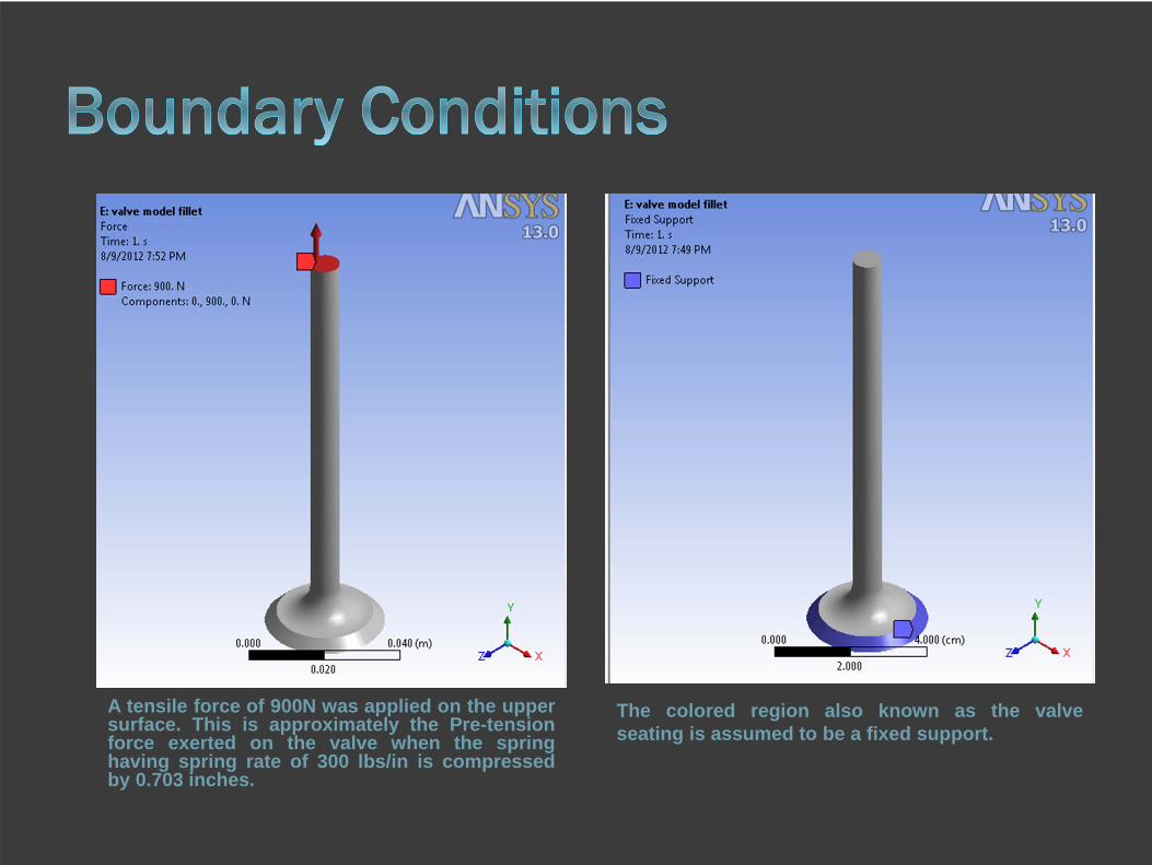
A tensile force of 900N was applied on the uppersurface. This is approximately the Pre-tensionforce exerted on the valve when the springhaving spring rate of 300 lbs/in is compressedby 0.703 inches.
The colored region also known as the valveseating is assumed to be a fixed support.

Mesh method was set totetrahedron elements and arelevance of 100 was used.
Mesh sizing properties wherealso set to fine to generate afiner mesh
Mesh statistics: Nodes: 51665 Elements: 31018


Fillet Radius Maximum Normal Stresses (Mpa)Equivalent
Stresses (Von Misses)
Shear Stress Total Deformation
X Y Z (MPa) (MPa) (mm)
Chamfer(45° angle) 11.605 35.439 11.581 31.76 10.678 0.010084
No fillet 76.998 80.104 81.26 69.363 38.683 0.014087
1 mm 83.111 73.172 82.97 91.567 51.436 0.013691
2 mm 54.456 47.169 56.438 63.468 36.019 0.013189
3 mm 42.282 35.201 41.455 49.253 26.946 0.012706
4 mm 33.902 28.429 34.112 40.205 22.574 0.012261
5 mm 27.066 24.186 28.272 33.213 18.343 0.011849
6 mm 22.978 22.485 23.227 28.227 15.578 0.011491
7 mm 19.72 21.646 19.676 24.106 13.475 0.011171
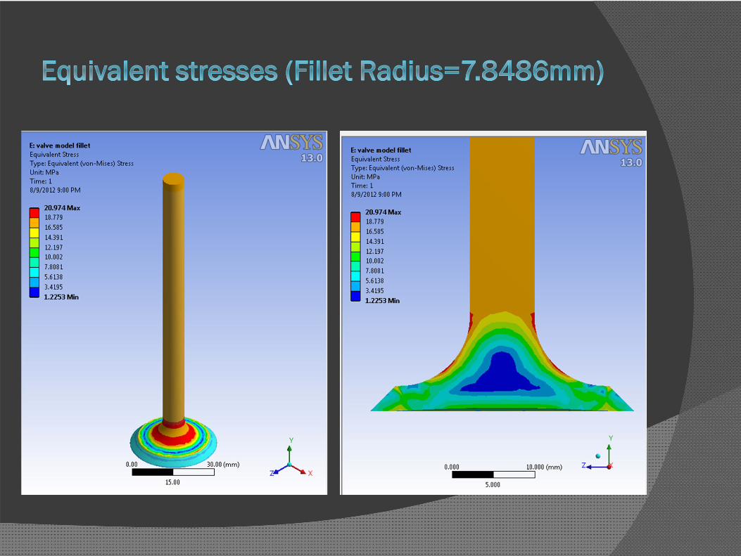
7.8786 mm 17.057 21.244 17.334 20.974 11.761 0.010937

0
10
20
30
40
50
60
70
80
90
100
Chamfer(45°angle)
No fillet 1 mm 2 mm 3 mm 4 mm 5 mm 6 mm 7 mm 7.8786 mm
Max
imum
Str
ess
(MPa
)
Fillet Geometry
Normal Stress in X-axis
Normal Stress in Y-axis
Normal Stress in Z-axis
Equivalent Stress
Shear Stress

0
0.002
0.004
0.006
0.008
0.01
0.012
0.014
0.016
Tota
l Def
orm
atio
n(m
m)
Fillet Geometry
Total Deformation (mm)

Transient Analysis could not be performed due in adequate computational resources thus time dependent inertial loads where ignored.
Model only simulates static loading that is conditions when engine is not running.
Impact loads that could occur during engine operation where not considered .
This analysis can only be used to observe stress concentration effects on different geometry.

Stress concentration occurs at the notch of the valve. Chamfering reduces normal stress along X and Z direction
but normal stresses along Y directions are not affectedgreatly.
Filleting the notch helps greatly reduces and the stressconcentration and distributes the stress equally among otherdirections as well.
Maximum stress values reduces with increase in fillet radius.