MAE 493N 593T Lec11
23
“Tribology in Mechanical Engineering” MAE 493N/593T Dr. Konstantinos A. Sierros West Virginia University Mechanical & Aerospace Engineering ESB Annex 263 [email protected]
-
Upload
kostassierros9374 -
Category
Documents
-
view
229 -
download
0
Transcript of MAE 493N 593T Lec11

8/8/2019 MAE 493N 593T Lec11
http://slidepdf.com/reader/full/mae-493n-593t-lec11 1/23
“Tribology in Mechanical Engineering”MAE 493N/593T
Dr. Konstantinos
A.
Sierros
West Virginia University
Mechanical & Aerospace Engineering
ESB Annex
263

8/8/2019 MAE 493N 593T Lec11
http://slidepdf.com/reader/full/mae-493n-593t-lec11 2/23
Wear
• Introduction‐Definition and measurement of wear
‐Classification of wear
• Mechanisms of wear
‐Seizure
‐ Melt wear
‐ Oxidation‐dominated wear
‐ Mechanical wear processes
‐Fatigue
wear
in
rolling
contacts
‐ Fretting and corrosion wear
‐ Erosive wear
• Third bodies and wear
‐Wear
by
abrasive
contaminants
‐ Interfacial ‘third’
bodies
‐ Debris analysis
• Further reading
http://www.engineering.leeds.ac.uk/ietsi/Research_Projects/Lubricant‐surface.shtml
DLC coating wear track in oil lubricated conditions
8/8/2019 MAE 493N 593T Lec11
http://slidepdf.com/reader/full/mae-493n-593t-lec11 3/23
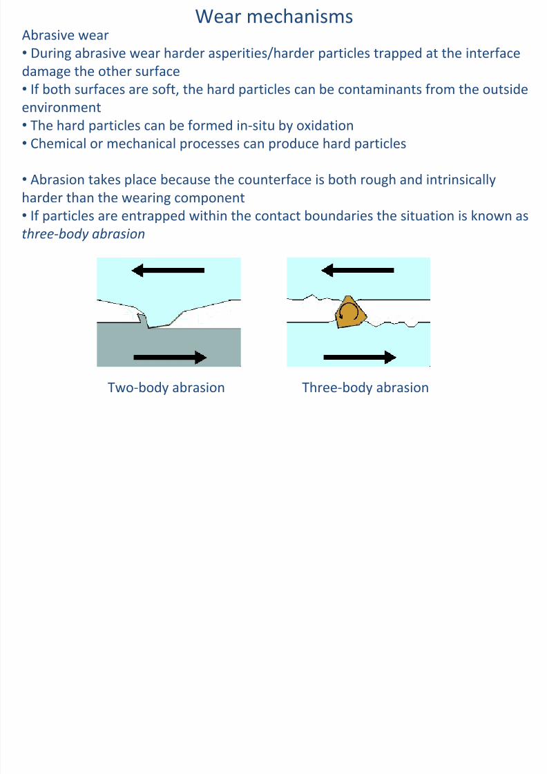
Abrasive wear
•
During abrasive wear harder asperities/harder particles trapped
at the interface
damage the
other
surface
•
If both surfaces are soft, the hard particles can be contaminants from the outside
environment
• The hard particles can be formed in‐situ by oxidation
• Chemical or
mechanical
processes
can
produce
hard
particles
•
Abrasion takes place because the counterface is both rough and intrinsically
harder than the wearing component
•
If
particles
are
entrapped
within
the
contact
boundaries
the
situation
is
known
as
three‐body abrasion
Wear mechanisms
Three‐body abrasionTwo‐body abrasion

8/8/2019 MAE 493N 593T Lec11
http://slidepdf.com/reader/full/mae-493n-593t-lec11 4/23
Wear mechanismsAbrasive wear
•
The surface topography during abrasive wear consists of long parallel grooves
running in
the
sliding
direction
http://maxxtorque.com/dieselcommunity/winter‐2009/oil‐bypass‐filtration‐system‐for‐lmm‐dmax
• Volume and
size
of
grooves
varies
from
light
scratching
up
to
severe
scratching
• Abrasive wear accounts for up to 50% of wear problems
•
The rate of damage to a surface in three‐body abrasion is relatively insensitive to
the hardness of the particles if they are at least 20% harder than the surface itself

8/8/2019 MAE 493N 593T Lec11
http://slidepdf.com/reader/full/mae-493n-593t-lec11 5/23
Wear mechanismsAbrasive wear
•
The most common contamination in industry comes from quartz or silica
minerals (60%
of
Earth’s
crust)
•
These particles have hardness around 8 GPa
and they can damage hardened
steel components (7‐8 GPa
hardness)

8/8/2019 MAE 493N 593T Lec11
http://slidepdf.com/reader/full/mae-493n-593t-lec11 6/23
Abrasive wear
•
During abrasive wear (using an equation of the same form as Archard’s) the
volumetric loss of a material is proportional to the distance slid and the intensity
of loading
If: Abrasive wear resistance = (wear volume)‐1
Then, Abrasive wear resistance is proportional to Hardness
Wear mechanisms
This has been confirmed experimentally in the early 1950s
(Kruschov
1957)

8/8/2019 MAE 493N 593T Lec11
http://slidepdf.com/reader/full/mae-493n-593t-lec11 7/23
Wear mechanisms
Kruschov
1957
Abrasive wear resistance is proportional to Hardness
Two‐body abrasion
(a)Pure metals
(b)Steels with varying
compositions and heat
treatments

8/8/2019 MAE 493N 593T Lec11
http://slidepdf.com/reader/full/mae-493n-593t-lec11 8/23
Wear mechanismsKruschov
1957
Abrasive wear resistance is proportional to Hardness
•
In such experiments specimens of each material in the form of cylindrical pins
are rubbed against abrasive paper/cloth carrying SiC or quartz particles
•
Relative wear resistance is equal to wear volume of
the sample divided by that of some standard material
tested under the same conditions
•
Relative wear resistance of a range of pure metals is
proportional to hardness

8/8/2019 MAE 493N 593T Lec11
http://slidepdf.com/reader/full/mae-493n-593t-lec11 9/23
Wear mechanisms• For alloys the situation is more complicated
• Steels
of
different
compositions
and
heat
treatments
(i.e.
different
hardnesses)
exhibit linear relationships but of different slopes from that of pure metals
• This is attributed to details in the microstructures of such alloys

8/8/2019 MAE 493N 593T Lec11
http://slidepdf.com/reader/full/mae-493n-593t-lec11 10/23
Wear mechanisms
•
Models of abrasive wear always assume that the deformations of the harder
surface are
negligible
compared
to
those
of
the
softer
surface
•
They are also based on a single hard asperity moving across a softer previously
unreformed surface

8/8/2019 MAE 493N 593T Lec11
http://slidepdf.com/reader/full/mae-493n-593t-lec11 11/23
Wear mechanisms
•
A conical asperity of semi‐angle 90o
–
θ
carrying a normal
load
W indents
a soft
surface to depth h
•
θ
represents the ‘average’
roughness of
the abrading surface
•
If
the
asperity
starts
sliding,
the
wear
rate
will be given by;
ϑ cot2×= hw
The depth h can be related to hardness H and the normal load W can be expressed in
terms of h and H as follows;
H hW ××=2)cot(
2
ϑ π
And finally;
H
W
w ×=π
ϑ tan2

8/8/2019 MAE 493N 593T Lec11
http://slidepdf.com/reader/full/mae-493n-593t-lec11 12/23
Wear mechanisms
H
W
w ×=π
ϑ tan2
This is like Archard’s equation
K (Wear coefficient)
The above suggests that rougher surfaces (larger θ) will exhibit larger K and thus
more wear damage
• However, the simple equation overestimates the wear observed in
reality
• If we set θ=1o , the predicted value of K is around 0.01
In reality, measured values of K in two‐body abrasion of metals are observed to lie
in the
range
of
5x10‐
3
–
50x10‐
3
8/8/2019 MAE 493N 593T Lec11
http://slidepdf.com/reader/full/mae-493n-593t-lec11 13/23
Wear mechanisms
•
The discrepancy between predicted and measured values of K is due to our
assumption that
all
material
from
the
groove
is
lost
from
the
surface
•
In an actual fact, experimental observation showed that some
material is
actually detached (due to microcutting) while the remainder is piled up at the
wear track edges (due to ploughing)

8/8/2019 MAE 493N 593T Lec11
http://slidepdf.com/reader/full/mae-493n-593t-lec11 14/23
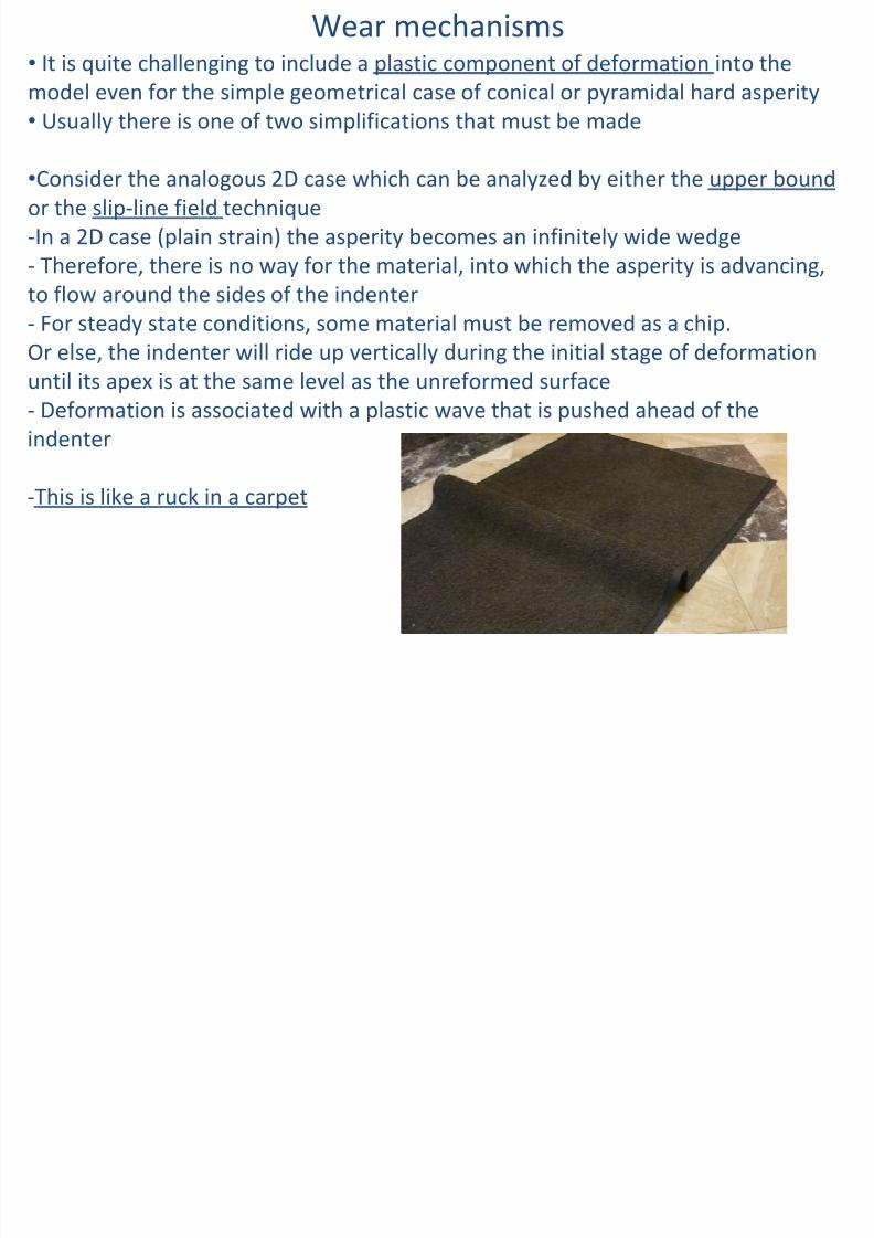
Wear mechanisms
•If we attempt to model the asperity as a symmetrical pyramid then we can have
only some
material
lost
from
the
surface
•
The extent of subsurface deformation can be judged form the extent of the
wedge/prow of material in front of the leading edge
h

8/8/2019 MAE 493N 593T Lec11
http://slidepdf.com/reader/full/mae-493n-593t-lec11 15/23
Wear mechanisms
•The material in the ridges does not contribute greatly to wear because it is not
detached
from
the
surface•
The relative volumes appearing in the ridges and the produced chips depend
on the geometry of the hard asperity
•
In the symmetrical pyramid case the geometry is described by angles ψ
and φ
as
shown
in
figure
5.8b
Angle between leading edge and direction of
motion is called attack angle
ψ
Angle at the base of pyramidal asperity (2φ) is
called dihedral angle
If the
attack
angle
exceeds
some
critical
value
ψc
, there is a significant contribution to wear
by micromachining
If the angle is less than the critical value, the
process is
dominated
by
ploughing
or
rubbing

8/8/2019 MAE 493N 593T Lec11
http://slidepdf.com/reader/full/mae-493n-593t-lec11 16/23
W h i

8/8/2019 MAE 493N 593T Lec11
http://slidepdf.com/reader/full/mae-493n-593t-lec11 17/23
Ploughing: The surface topography is much modified but a small proportion
of the displaced material is actually detached from the surface
Micromachining:
A
much
higher
proportion
of
the
plastically
deforming
material is lost as wear debris
Wear mechanisms
Wear mechanisms

8/8/2019 MAE 493N 593T Lec11
http://slidepdf.com/reader/full/mae-493n-593t-lec11 18/23
Wear mechanismsTransition from ploughing to micromachining
•The dihedral angle can also influence the wear mode
• If 2φ
is small, the asperity is like a knife cutting through the surface
• As φ
increases
the
asperity
gets
‘bluffer’
•
When 2φ=180o the asperity will be moving with one of its flat faces forward
rather than with one of its edges
‐
The
effect
of
both
angles
is
illustrated
on
the
wear‐
mode
diagram
above
8/8/2019 MAE 493N 593T Lec11
http://slidepdf.com/reader/full/mae-493n-593t-lec11 19/23
Wear mechanismsSli li fi ld

8/8/2019 MAE 493N 593T Lec11
http://slidepdf.com/reader/full/mae-493n-593t-lec11 20/23
ea
ec a s sSlip‐line field
• Fig 5.10a shows a slip‐line field for this deformation mode
•
If friction between the hard asperity and the deforming surface
is high, the
plastic wave
may
shear
off
from
the
surface
along
the
path
AB
(Fig
5.10b)
•
When one prow has been removed as a wear fragment the indenter digs once
more and the process restarts
•
Larger values of attack angle ψ
favour cutting. h is depth of presentation of the
asperity into
the
softer
surface
(Fig
5.10c)
Wear mechanismsUpper bound approach

8/8/2019 MAE 493N 593T Lec11
http://slidepdf.com/reader/full/mae-493n-593t-lec11 21/23
Upper bound approach
• The 3D aspect of the problem is maintained in this case
• Forces and geometry are related
• Indenter is assumed to be rigid and the abraded material to be perfectly plastic
• The material flows at a constant shear stress h
•
This approach is also challenging but it has been shown that reasonable
agreement
between
theory
and
experiment
can
be
achieved‐Mainly for the transition from ploughing to micromachining
‐ And the magnitude of the tangential force
Wear mechanisms

8/8/2019 MAE 493N 593T Lec11
http://slidepdf.com/reader/full/mae-493n-593t-lec11 22/23
In reality…
• A wear surface is formed as a result of many wear events
• These wear events follow one another during the lifetime of the
component
• The interaction of individual wear events is not well understood to date
•
There
is
no
fully
satisfactory
way
of
predicting
abrasive
wear
rates
(component
lives) in terms of their initial surface geometry/topography and
material properties

8/8/2019 MAE 493N 593T Lec11
http://slidepdf.com/reader/full/mae-493n-593t-lec11 23/23
Summary
• Wear mechanisms
‐
Abrasive wear