
MAE 412-Machines and Mechanisms II Professor: Dr. Krovi ...€¦ · MAE 412-Machines and Mechanisms...
37
MAE 412-Machines and Mechanisms II Professor: Dr. Krovi Final Project-Catapult Report December 13, 2002 Group G: Matthew Mandiak Steven Matroniano Karen Maynard John McDonald Patrick McQuillen David Meehan James Meyer
Transcript of MAE 412-Machines and Mechanisms II Professor: Dr. Krovi ...€¦ · MAE 412-Machines and Mechanisms...

MAE 412-Machines and Mechanisms II Professor: Dr. Krovi
Final Project-Catapult Report December 13, 2002
Group G:
Matthew Mandiak Steven Matroniano
Karen Maynard John McDonald
Patrick McQuillen David Meehan James Meyer

2
Introduction
Our project was to design a catapult system to throw a squash ball using at least a
four-bar mechanism. Our success for the project was judged on how well we could construct
the catapult with the resources and time we had available. This also included how well we
could analyze the four-bar using Solid Edge/Dynamic Designer, MATLAB, and by
hand. Competition wise our success was judged on how far our catapult could throw the
ball. It was also measured by the design, compactness and aesthetics which went into
produc ing the catapult. In all, our achievement was based on how well our group could work
as a team to complete all aspects of the project to the best of our abilities.
Constraints
The constraints that are present for our catapult system include:
? It must be a at least a four-bar mechanism
? The catapult must operate within a 2 foot by 2 foot window which includes the
base plate
? In order to cut costs and make it easier to construct, the mechanism must be made
out of wood
? No part of the mechanism can cross the plane where the judges will be measuring
the distance from
? Only one motor can be used to provide torque to the mechanism
? Mechanism must be able to be mounted to the base plate (table top) using 2 C
clamps
? Catapult must fire within 30 seconds of being started

3
Besides the fact that time and getting everyone to meet together was always an issue;
another constraint included the strength of the springs which we could place on our
mechanism to make it launch. Since we constructed it out of yardstick it did not allow for us
to use the strongest springs that the motor could support. We hooked up pulleys to the
mechanism to allow for the motor to pull more, but we still did not fully use all the power
which the motor could provide. By making the mechanism out of a stronger wood, would
have allowed for us to use stronger springs. Hence, this would have lead to a greater distance
in the competition.
Another constraint that we dealt with in the formulation of our four-bar was not to
make it extremely complex to the point where we could not analyze it with the various
programs. Nonetheless, our mechanism uses four springs , a sliding wheel and a pulley
system which made performing the analysis a bit tricky. However, it also allowed for us to
do better in the competition and design of the catapult.

4
Idea Generation
At our first group meeting, the goal was to discuss the constraints of the project
and to generate as many ideas as possible. By doing this the members of the group could
think about all the ideas and come to the next meeting with better ones based on what we
started with at the first meeting. We brainstormed, combined some good ideas and finally
were able to narrow them down into two basic options, a mechanism that launched the
ball, or a mechanism that impacted the ball.
Impact mechanism
Initially, with the time constraint in mind, this mechanism seemed easy to analyze
and build while maintaining enough velocity to impact the ball with reasonable force.
The fundamental strategy was to use the four-bar almost as a golf club where the impact
arm would swing around and hit the ball off a stand and send it off in the distance. A
double-rocker would be used to create the motion to impact the ball. The motor would be
placed at one of the bases to provided added torque to the mechanism.

5
ProE images of our original design, the longer link was designed to come around and hit the squash
ball off the ground
After the creation of a prototype, we determined that it was a valid idea in solid
edge but did not quite work as an actual mechanism for its purpose. The motor was not
strong enough to turn the links with enough velocity to make it worth optimizing. We
thought of incorporating pulleys and springs with this idea; however, a device that
impacts the ball does not give great distance. The ball itself absorbs so much energy that
even slamming it on the ground as hard as you can only sends it a meager 3-4 feet back
up. With that in mind, we decided to scrap that idea and try the launching mechanism.
We were lucky that we started early and had enough time to be able to completely change
our design and do adequate testing and optimizing.
Picture of the actual prototype for our first design

6
Launching Mechanism
Our next idea consisted of a sliding joint that incorporated pulleys and springs to
obtain the greatest distance of travel. The idea behind it is having the motor pull one of
the links down using the assistance of pulleys. There is then a wheel at the end of that
link that rolls along the launching link pulling it down as well. However, when the link
get to a certain position, the wheel rolls off the launching link and sends the ball flying
away. Springs extend as the links move back and helps the throwing arm throw the ball
an even greater distance. Additionally, the way the springs were positioned forced the
launching arm to release at about a 45° angle to further maximize the distance. There
could be very strong springs on the throwing arm creating a force in the opposite
direction but because of the use of pulleys, the motor easily pulled the system back.

7
Description of the Mechanism
Our catapult uses a sliding joint to allow for the coupler link to move down the arm
of the input link and then fall off and release the input link forward. The input link shoots
forward to its starting pos ition and releases the ball as previously mentioned at a 45° angle
for maximum range of the throw.
Picture of our Catapult in the resting position, as can be seen the pulleys are hooked up to the follower link
which pulls back the input link to launch the ball
In addition, a pulley system is hooked up to the follower link and motor which is
what “loads” the catapult for the launch. Therefore, as the follower link is pulled back by the
motor it is hooked up to the cylindrical coupler link which slides down the input link until it
falls off towards the top of it. This can be seen more clearly in the drawing below.
8
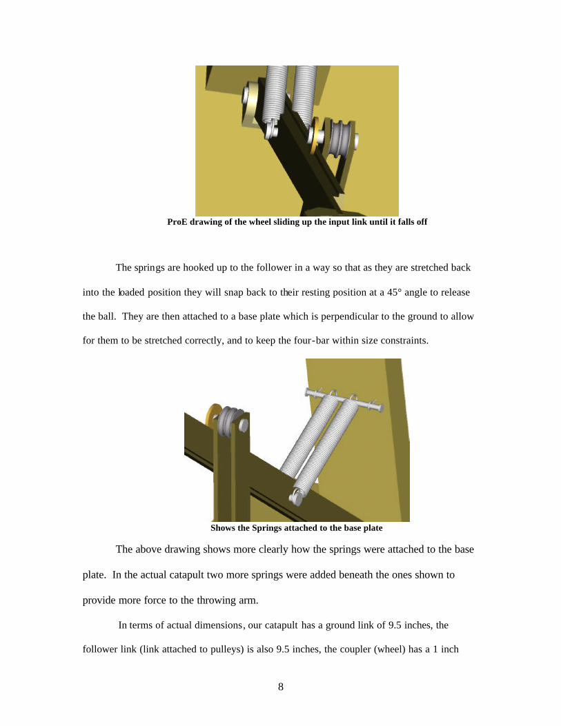
ProE drawing of the wheel sliding up the input link until it falls off
The springs are hooked up to the follower in a way so that as they are stretched back
into the loaded position they will snap back to their resting position at a 45° angle to release
the ball. They are then attached to a base plate which is perpendicular to the ground to allow
for them to be stretched correctly, and to keep the four-bar within size constraints.
Shows the Springs attached to the base plate
The above drawing shows more clearly how the springs were attached to the base
plate. In the actual catapult two more springs were added beneath the ones shown to
provide more force to the throwing arm.
In terms of actual dimensions, our catapult has a ground link of 9.5 inches, the
follower link (link attached to pulleys) is also 9.5 inches, the coupler (wheel) has a 1 inch

9
radius, and the throwing arm (input link) is approximately 18 inches when it is released from
the coupler link to throw.
Technically, our mechanism can be classified as a Grashof triple -rocker since the
longest plus the shortest link is greater than the length of the other two links. This is
supported by the fact that no link can make a full revolution when it is rotating.
An Isometric shot of our catapult
We also used four D-cell batteries to operate our catapult and to make sure it fired
within the 30 second time limit. With all the springs attached the catapult took 26 seconds to
fire. For precision shooting with two less springs the time was only 20 to 21 seconds.

10
Dynamic Designer/Solid Edge Prototype
The Figure below shows our virtual prototype in Dynamic Designer with the input
link (throwing arm) at a maximum velocity. As can be seen this occurs at approximately 45°
to the ground. This is what we wanted since it is when the ball will have maximum range of
flight when it is in the air. Solid Edge also proved helpful in determining the configuration of
the catapult. In order to optimize the velocity and acceleration of the various links we simply
played around with the dimension in the program until we found a configuration that was
best.
Picture of our Virtual Four-bar with the velocity of throwing arm at maximum
As the following plots show a Dynamic Designer prototype was created to help
analyze the mechanism. This was useful to some extent in determining when and where the
various links would be would be at a maximum velocity and acceleration.

11
0.00 0.07 0.14 0.21 0.28 0.35 0.42 0.49 0.56 0.63 0.70Time (sec)
359
360
360
361
361
Ang
ular
Vel
- M
ag (
deg/
sec)
Plot of the Angular Velocity of the follower link pulling back the throwing arm
As can be seen above, the link which pulls back the throwing arm has a constant
velocity of 350 degrees/second. Since the pulleys were hooked up to this link, this
information was helpful because we now knew the pulleys and motor would not experience
any increase in velocity or force.
0.00 0.07 0.14 0.21 0.28 0.35 0.42 0.49 0.56 0.63 0.70Time (sec)
-1
-0
0
1
1
Ang
ular
Acc
el -
Mag
(de
g/se
c**2
)
Plot of Angular Acceleration of follower link

12
The plot of acceleration of the follower link used to pull back the input link to fire the
mechanis m also has no acceleration which is what we wanted. Since this link is hooked up to
the motor any increase or decrease in acceleration may not have been suitable for the motor
to support. This way it provides a smooth and constant pull for the system.
0.00 0.07 0.14 0.21 0.28 0.35 0.42 0.49 0.56 0.63 0.70Time (sec)
12
374
737
1100
1462
Ang
ular
Vel
- M
ag (
deg/
sec)
Plot of Angular Velocity of coupler link (wheel)
The plot above shows a more interesting pattern obtained for the coupler link. The
coupler link was represented as a wheel that slides along the input link and eventually falls
off to “fire” our mechanis m. As is shown its velocity stays relatively constant until around
0.25 seconds when it shoots up to 1462 deg/sec. This is the point where the coupler falls off
the input link and releases it forward. In real life this time was more like 26 seconds;
however, the virtual prototype was used for estimations and to get a better idea of how the
system would work when constructed.

13
0.00 0.07 0.14 0.21 0.28 0.35 0.42 0.49 0.56 0.63 0.70Time (sec)
63
3327
6592
9856
13120
Ang
ular
Acc
el -
Mag
(de
g/se
c**2
)
Plot of Angular Acceleration for coupler link (wheel)
The above plot shows how the acceleration of the wheel changes as it is pulled back
by the pulleys and motor. As can be seen as it gets closer to firing the acceleration steadily
increases. This can be attributed to the fact that as the motor pulls the follower and coupler
links back it becomes easier and quicker due to the pulley system. Therefore, the angular
acceleration of the coupler speeds up a little bit. It then drops off after 0.30 seconds which is
when the coupler is no longer on the input link and the mechanism has already fired the ball.

14
0.00 0.07 0.14 0.21 0.28 0.35 0.42 0.49 0.56 0.63 0.70Time (sec)
0
105
210
316
421
Ang
ular
Vel
- M
ag (
deg/
sec)
Plot of Angular Velocity of the throwing arm (input link)
The above plot shows how the angular velocity of the throwing arm (follower link)
changes as it is pulled back and eventually released from the coupler. Therefore, as it is
pulled back the velocity stays relatively consta nt at around 150-175 deg./sec. The further
back it goes it eventually decreases to almost zero and then is unleashed and increases to over
400 deg./sec. This result is exactly what happened when we built the catapult since the
throwing arm would come back to almost a parallel position to the ground, remain almost
motionless for a few seconds and then fire.

15
0.00 0.07 0.14 0.21 0.28 0.35 0.42 0.49 0.56 0.63 0.70Time (sec)
16
458
900
1343
1785
Ang
ular
Acc
el -
Mag
(de
g/se
c**2
)
Plot of Angular Acceleration of the throwing arm (input link)
The plot for angular acceleration of the throwing arm gives predictable results for the
catapult by the fact that as the throwing arm is pulled back it steadily decreases in
acceleration. However, once the arm is released at around 0.25 seconds the acceleration goes
almost straight up to 1800 deg./sec^2 in less than five hundredths of a second. This is
obviously when the link is released from the rest of the mechanism to fire the catapult. This
result obtained in Dynamic Designer predicted exactly how the catapult’s throwing arm
would respond with the actual prototype. As the throwing arm came back it steadily got
slower and slower until almost at rest before being released to throw the ball.
In all, the results we obtained in Dynamic Designer and Solid Edge predicted very
well how our catapult would perform once constructed. We knew if built correctly the ball
would go very far due to the sudden burst in angular velocity and acceleration experienced by
the throwing arm.

16
Simulation Based Design
Our Solid Edge/Dynamic Designer prototype was vital to finding the dimension in
which to construct our actual prototype. It was clear that our throwing arm could be no
longer than 24 inches in order to comply with the constraints. Therefore, by creating the
mechanism in Solid Edge proved to be interesting since it allowed for us to analyze our
catapult with the dimensions that we were going to use to construct.
By playing around with numbers in solid edge for the various link lengths also
allowed for the best configuration to be determined. This can be shown by the fact that the
ground link is 9.5 inches long as is the follower link which is responsible for pulling the
throwing arm back. This configuration worked best in Dynamic Designer so we assumed
would also work best with the real thing.
We knew before-hand that we wanted to release the ball at a 45° angle to the ground
since this is the appropriate angle for maximum range. Therefore, we went about setting up
our simulation to achieve results at this position. This was also helpful in showing the force
and velocity with which the ball would be released based on the values obtained for the joint
linking the throwing arm to the ground. This then allowed for use to get a better idea of the
distance we would be able to throw the ball for the competition.
The most useful aspect of the simulation based design which we created was that it
was helpful in making sure we got our constraints right. Through the virtual prototype it was
easy to make sure that we were within the size requirements for the catapult. We could then
go about creating our prototype in Solid Edge/Dynamic Designer in order to create the most
powerful catapult for the design we wanted to use.
Some aspects of the catapult were hard to simulate in Dynamic Designer which
included the proper springs. It is easy to place a certain spring force around a joint in the

17
program; however, finding the proper spring constant in real life that was also the right length
was a little bit more tricky. Therefore, we experimented with a couple springs with our
physical prototype to find ones that we liked.

18
Analysis
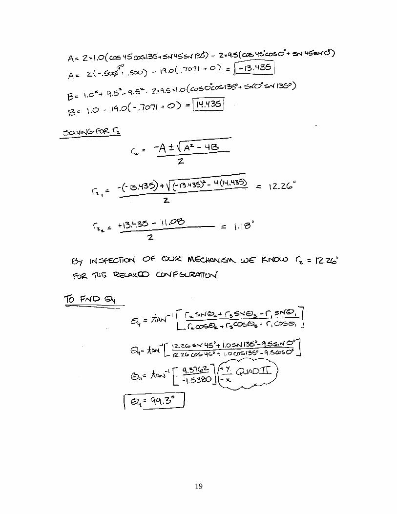
19

20
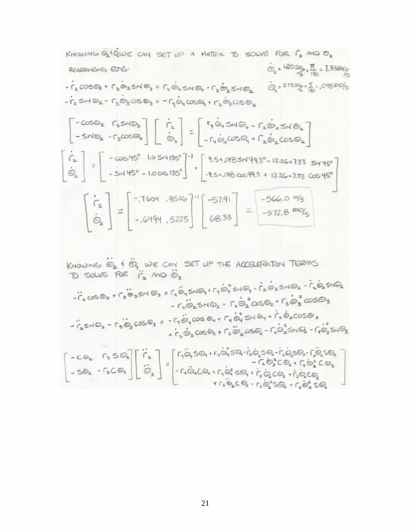
21

22

23

24

25
Matlab Based Analysis
Position: %Position analysis for our four-bar catapult. clear all % Input values for all known linkage parameters r1 = 9.5; % Input crank % r2 is an unknown r3 = 1; % Slider Offset r4 = 9.5; % Coupler th1 = 0; % Angle of the Ground Link %th2 is unknown %th3 unknown = th2 + 90*pi/180 th4 = 135*pi/180; % Desired position of the input crank th4prime = 15*pi/180; % Desired arm release point % Using Pythogoras theorem r2_Limit1 = sqrt((r1+(r4-r3)*cos(th4))^2+((r4-r3)*sin(th4))^2) r2_Limit2 = sqrt((r1+((r4-r3)*cos(th4prime)))^2 + (r4*sin(th4prime))^2) stroke = r2_Limit2-r2_Limit1 th2 = (atan(((r4-r3)*sin(th4))/(r1+(r4-r3)*cos(th4))))*(180/pi) th2prime = (atan(((r4-r3)*sin(th4prime))/(r1+(r4-r3)*cos(th4prime))))*(180/pi) th2_range = th2 - th2prime th3 = th2 + 90 th3prime = th2prime + 90 th3_range = th3 - th3prime
Position Output: r2_Limit1 = 6.9500 r2_Limit2 = 17.8802

26
stroke = 10.9303 th2 = 59.8609 th2prime = 7.0809 th2_range = 52.7800 th3 = 149.8609 th3prime = 97.0809 th3_range = 52.7800

27
Velocity: %velocity calculation for r2dot clear all %state known variables %r2dot is unknown th1dot = 0; th2dot = .92; %rad/sec th3dot = 13; %rad/sec th4dot = .08; %rad/sec th2 = 58.86*pi/180; th3 = th2+90*pi/180; th4 = 135*pi/180; r2 = 6.95; %in r3 = 1; %in r4 = 9.5; %in %differentiated loop equations %x composition r2dotx = ((r2*(th2dot)*sin(th2))+(r3*(th3dot)*sin(th3))-(r4*(th4dot)*sin(th4)))/(cos(th2)) %y composition r2doty = ((r4*(th4dot)*cos(th4))-(r2*(th2dot)*cos(th2))-(r3*(th3dot)*cos(th3)))/(sin(th2)) %r2dot r2dot = sqrt((r2dotx^2)+(r2doty^2))
Velocity Output: r2dotx = 22.5435 r2doty = 8.5089 r2dot = 24.0959

28
M-file for Velocity Calculation: %velocity calculation for r2dot clear all %state known variables %r2dot is unknown th1dot = 0; th2dot = .92; %rad/sec th3dot = 13; %rad/sec th4dot = .08; %rad/sec th2 = 58.86*pi/180; th3 = th2+90*pi/180; th4 = 135*pi/180; r2 = 6.95; %in r3 = 1; %in r4 = 9.5; %in %differentiated loop equations %x composition r2dotx = ((r2*(th2dot)*sin(th2))+(r3*(th3dot)*sin(th3))-(r4*(th4dot)*sin(th4)))/(cos(th2)) %y composition r2doty = ((r4*(th4dot)*cos(th4))-(r2*(th2dot)*cos(th2))-(r3*(th3dot)*cos(th3)))/(sin(th2)) %r2dot r2dot = sqrt((r2dotx^2)+(r2doty^2))
29
Project Construction
Basic design
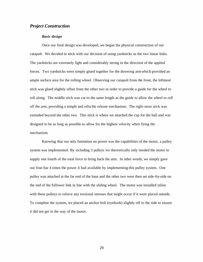
Once our final design was developed, we began the physical construction of our
catapult. We decided to stick with our decision of using yardsticks as the two linear links.
The yardsticks are extremely light and considerably strong in the direction of the applied
forces. Two yardsticks were simply glued together for the throwing arm which provided an
ample surface area for the rolling wheel. Observing our catapult from the front, the leftmost
stick was glued slightly offset from the other two in order to provide a guide for the wheel to
roll along. The middle stick was cut to the same length as the guide to allow the wheel to roll
off the arm, providing a simple and relia ble release mechanism. The right-most stick was
extended beyond the other two. This stick is where we attached the cup for the ball and was
designed to be as long as possible to allow for the highest velocity when firing the
mechanism.
Knowing that our only limitation on power was the capabilities of the motor, a pulley
system was implemented. By including 3 pulleys we theoretically only needed the motor to
supply one fourth of the total force to bring back the arm. In other words, we simply gave
our four-bar 4 times the power it had available by implementing this pulley system. One
pulley was attached at the far end of the base and the other two were then set side-by-side on
the end of the follower link in line with the sliding wheel. The motor was installed inline
with these pulleys to relieve any torsional stresses that might occur if it were placed outside.
To complete the system, we placed an anchor bolt (eyehook) slightly off to the side to ensure
it did not get in the way of the motor.

30
Close-up of the motor and eyehook used to secure the fishing line
Fishing line was used as our connection for this system, it ran from the motor, around
one of the pulleys on the rotating arm, through the grounded pulley, back to the second pulley
on the rotating arm, and then to the anchor. We chose fishing line because it is extremely
strong in tension, and much more durable than most fibrous threads and ropes. It is also
fairly frictionless when rotating around the pulleys, so it technically did not matter if the
wheels actually rotated.
The rolling wheel, which acted as a sliding link, needed to be made from wood, due
to the project requirements. Since we figured this wheel to be under considerable stress, and
needed it to be quite thin, we created it from the toughest wood readily available in our work
area.
The next piece in our design was a small board in front of the throwing arm that we
would attach the springs to. We inserted eyehooks in the center and sides to provide for
variable springs. This proved beneficial for precision shooting since any of the springs could
be easily taken off and put back on.
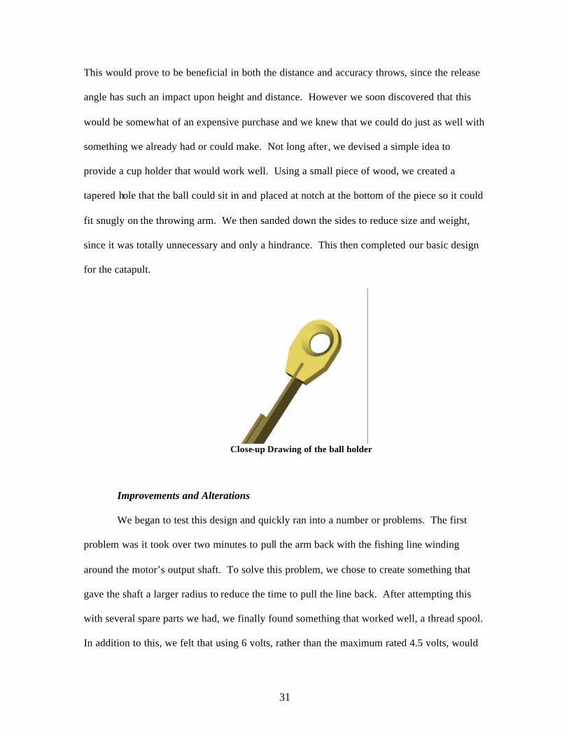
The final part was the holder for the ball. We decided to start simple and invest in a
small aluminum spoon or similar obje ct which could be bent and flexed into a desirable angle.
31
This would prove to be beneficial in both the distance and accuracy throws, since the release
angle has such an impact upon height and distance. However we soon discovered that this
would be somewhat of an expensive purchase and we knew that we could do just as well with
something we already had or could make. Not long after, we devised a simple idea to
provide a cup holder that would work well. Using a small piece of wood, we created a
tapered hole that the ball could sit in and placed at notch at the bottom of the piece so it could
fit snugly on the throwing arm. We then sanded down the sides to reduce size and weight,
since it was totally unnecessary and only a hindrance. This then completed our basic design
for the catapult.
Close-up Drawing of the ball holder
Improvements and Alterations
We began to test this design and quickly ran into a number or problems. The first
problem was it took over two minutes to pull the arm back with the fishing line winding
around the motor’s output shaft. To solve this problem, we chose to create something that
gave the shaft a larger radius to reduce the time to pull the line back. After attempting this
with several spare parts we had, we finally found something that worked well, a thread spool.
In addition to this, we felt that using 6 volts, rather than the maximum rated 4.5 volts, would
32
not harm the motor and speed up its operation (since our motor endured a test of 19.5 volts,
and still worked properly, 6 volts would most likely not have any adverse effect). Attaching
the spool and increasing the motor power brought the time down to around 26 seconds.
Following this we were then unsure about how strong of springs we could use.
Through calculations we figured the catapult and motor could support anywhere between 20
and 25 pounds of force. However, finding the right size springs with the correct spring
constant proved difficult so we had to test out a number of springs. We started with fairly
light springs, but realized our four-bar and motor could take more, so we put on springs with
a higher spring constant. Once this seemed to work, we instantly wanted to try something
stronger. Purchasing springs in which we knew would more than likely be too much for the
motor we connected them anyway. To see how strong these springs were we manually
pulled back the arm to get a feel. This caused the front board in which the springs were
attached to break off, which actually turned out to be beneficial, since it pointed out a hidden
weak point. From all of this, we decided to stick with the more stable springs and strengthen
the front board for the springs. In addition, to eliminate from this happening again we affixed
a block in front of the spring-base to counteract the forces.
At this point, our four-bar was in shape for distance testing, and again, we hit another
problem. The throwing arm’s starting angle was at a degree in which the ball did not stay in
the holder. We chose to fix this problem by merely gluing something to the holder to support
the ball when at rest. But we did not want whatever was glued there to interfere in any way
with the release of the ball. Any friction the ball encountered when released would decrease
our performance and distance. Our decision was then to place a small amount of hot glue just
in front of the tapered hole, so that the ball would rest on the solidified glue when in the
upright positon. It would then settle into the tapered hole when the arm was pulled back,

33
prior to release. However, the glue failed to efficiently hold the ball, which led to gluing a
small piece of wood to the holder. This turned out to work very well for the catapult.
As we continued testing, we noticed another dilemma: our rotating arm had so much
torque applied to it that it flexed to an unsafe degree. It seemed as though it would snap off
when it was pulled back since there was so much shear force acting on the rotating wheel.
We chose not to reduce the amount of force, but rather to restrain the arm’s flexing motion
instead. This was done by first adding washers to the inside of the ground joint reducing any
motion other than pure rotation about the joint; and second by replacing the outside bar of the
rotating link with a piece of wood that was four times the thickness and much stronger than
the original. By doing both of these, the link no longer strayed from the desired movement.
The testing continued and went well until yet another problem came about. Dur ing
one test, the sliding wheel did not release, but instead rode along the extended part of the
throwing arm. To correct this, we tightened the bolt on the wheel to keep it from traveling
astray. This correction led to another problem though, that when the wheel was tightened, it
pinched the guide on the throwing arm and it no longer rotated. This friction brings an
unnecessary strain to the motor, so we just figured the best solution was to make sure that the
bolt was tightened to just the right amount prior to every throw.

34
ProE drawing of the final design for our Catapult
Our final problem we encountered while constructing our catapult was due to its size.
We took measurements to make sure we were still within the requirements; however, our
length extended to beyond the maximum of 24 inches. We didn’t have much room for
shortening without redoing the design and thus we just tried to shorten everything possible
and hope for the best. First we shortened the throwing arm as much as possible to where the
wheel could still roll off. Then we sanded down the ball holder; however, it still remained
too long. We realized the only thing left to do was eliminate the front piece of wood holding
the spring board in place. After cutting this part of the base off we just barely fit under the
maximum 24 inches. To then re-strengthen the board holding the springs up we used an L-
bracket and fifty-pound zip-ties in conjunction with wood glue. After this, we were finally
complete with the construction and ready to compete.
35
Our Performance at the Competition Our catapult performed just as expected during the competition to the delight of all
our team members. For the distance portion of the competition we finished tied for third
place at 38 feet. This was exactly the distance we had anticipated throwing due to the testing
we had performed in the days leading up to the competition. Therefore, our catapult was a
success with what we wanted it to perform and how it performed.
Our catapult was also very repeatable by the fact that all three of our distance throws
were within just a few feet of one another. Our first attempt of 38 feet was followed by
consecutive throws of 37 and 35.5 feet. This was also another success for our team which
had anticipated the catapult throwing about the same distance each time.
The only complication that we had was that one of our gears stripped out while we
were trying to complete the precision shooting portion of the competition. Therefore, we had
to wait until the end of the competition to finish our last two throws with a new motor.
Our success during the precision shooting was mixed since we first hit the side of the
garbage can at 15 feet and then our final two throws at the end of the competition both hit the
garbage can at 20 feet. However, Dr. Krovi allowed for us to have another throw in which
we soundly placed the ball in the basket at 20 feet. Therefore, our mechanism was precise by
the fact that it hit the garbage can with every throw that we took; however, if we had just a
little more loft it would have been perfect.
In order for our catapult to perform during the precision shooting we removed the two
lower (stronger) springs for our fist attempt and left the longer (weaker) springs in place.
From our testing we figured this would land the ball about 15 feet from the catapult. Which
it did, but we did not have the right angle to put it in the garbage can. For our attempts at 20
feet we re-attached the smalle r springs and removed the lo nger ones. From our testing this

36
again proved to be about 20 feet, however we needed just a little bit more loft since both hit
the top of the garbage can.
The pulley system we put in place to help reduce the amount of force the motor had
to pull also worked as good as it was designed. Through our calculations the pulleys were set
up to provide a 4 to 1 mechanical advantage on the motor.
In addition to finishing in third place for the distance portion of the competition, we
also finished in third place for design, compactness and aesthetics as determined by the
judges. Our score of 92.6 was only eclipsed by two groups who had scores of 93 and 96.4,
respectively. This was another success for our group, who were all very excited with these
results.
If we were given the opportunity to re-design our catapult one of the first things we
would do would be to add lubricant to the joints of the four-bar. This was probably poor
judgment on our part to not use any lube in the first place, but we cannot look back with
regrets. Therefore, adding lubricant would only have helped the mechanism work better and
allow for more speed with the throwing arm.
The only major change we would have performed would be to use heavier and
stronger wood to make the four-bar. This would then allow for us to place stronger springs
on the mechanism and get it to have more force when it was released. The yardsticks that we
used could only support roughly 25 to 30 pounds of force from the springs before it would
break.
This was proven by the fact that after the competition we removed the springs on top
and replaced them with ones that we much stronger. Everyone knew that it would break the
catapult, but it was the most fun we had as a group. With the heavier springs the motor was
still able to pull the arm back with the help of the pulleys and release the ball. The ball shot
out just before the throwing arm snapped in half and destroyed our catapult. However, the

37
ball struck the second floor ceiling of the student union “flag” room roughly 80 to 90 feet
from where it was shot and 30 to 35 feet in the air. We do not know any numbers on what
the velocity of the ball was when it hit the ceiling, but it can be safe to assume it might have
traveled as far as 130 to 140 feet. This obviously would have easily won the competition and
garnered us some fame. However, our group has no regrets on how things turned out and
were ecstatic to finish the way we did.