MADSEN Zodiac - Reference Manual (EN) - Natus
212
MADSEN Zodiac Reference Manual Doc. No.7-50-1610-EN/07 Part No.7-50-16100-EN
Transcript of MADSEN Zodiac - Reference Manual (EN) - Natus

MADSEN ZodiacReference Manual
Doc. No.7-50-1610-EN/07Part No.7-50-16100-EN

Copyright notice© 2016, 2020 Natus Medical Denmark ApS. All rights reserved. ® Otometrics, the Otometrics Icon, Aurical,Madsen, HI-PRO 2,Oto-scan, ICS and HORTMANN are registered trademarks of Natus Medical Denmark ApS in the U.S.A. and/or other countries.
Version release date2020-06-15 (217208)
Technical supportPlease contact your supplier.
MADSEN Zodiac2

Table of Contents
1 Introduction to MADSEN Zodiac 91.1 The Otosuite Immittance module 101.2 Intended use 11
1.2.1 Contraindications 111.3 About this manual 121.4 Typographical conventions 131.5 Navigating this manual 13
2 Unpacking and installation 142.1 Unpacking 142.2 Storing 142.3 Installing Zodiac 14
2.3.1 Powering the device 152.3.2 Switching the device on and off 162.3.3 Connecting to the PC 162.3.4 Reconnecting to the device 162.3.5 Configuring the device 16
2.4 Communication between Otosuite and Zodiac 172.4.1 Configuring the Immittance module 172.4.2 Test device information 18
3 The built-in printer 19
4 Views of Zodiac 214.1 Front view 214.2 Bottom view 22
5 The Zodiac probes 235.1 The Quick Check probe 235.2 The diagnostic probes 25
5.2.1 The diagnostic probe and shoulder strap 255.2.2 Using two probes with the device 275.2.3 The contralateral phone 27
6 MADSEN Zodiac test controls 296.1 The Quick Check front panel 296.2 The Diagnostic and Clinical front panel 316.3 The Zodiac menu 346.4 Special tests 35
7 Preparing for testing 377.1 Preparing the test environment 377.2 Hygienic precautions 377.3 Probe check 377.4 Creating a new session 387.5 Using a test setup 397.6 Inspecting the patient’s ear 397.7 Fitting the eartip on the probe 39
MADSEN Zodiac 3

7.8 Fitting the probe in the patient’s ear 40
8 Testing with Zodiac Quick Check - Stand-Alone 448.1 Starting a measurement 448.2 The Quick Check measurement screen 46
9 Testing with Zodiac Diagnostic or Clinical - Stand-Alone 499.1 Quick Check testing 49
9.1.1 Starting a measurement 499.1.2 The Quick Check measurement screen 52
9.2 Sequence testing 549.2.1 Selecting a test sequence 549.2.2 Running a test sequence 54
9.3 Tympanometry testing 559.3.1 The Tympanometry screen 57
9.4 ETF-I (Eustachian Tube Function - Intact) testing 599.5 Acoustic reflex testing 609.6 Reflex Threshold testing 60
9.6.1 The Reflex Threshold screen 629.7 Reflex Decay testing 64
9.7.1 The Reflex Decay screen 669.8 Manual Tympanometry 67
9.8.1 The Manual Tympanometry screen 689.9 Admittance (Y) Recorder 69
9.9.1 The Admittance (Y) Recorder screen 719.10 ETF-P 72
9.10.1 The ETF-P screen 73
10 The Otosuite Immittance module 7510.1 Otosuite toolbar icons and control panels 7510.2 Shortcut keys 8010.3 Leakage and other probe problems 82
11 Testing with Zodiac Quick Check - PC-based 8411.1 Starting a measurement 8411.2 The Quick Check measurement screen 86
12 Testing with Zodiac Diagnostic or Clinical - PC-based 8812.1 Sequence testing 88
12.1.1 Setting up a sequence 8812.1.2 Running a test sequence 89
12.2 Quick Check testing 8912.3 Tympanometry testing 90
12.3.1 The Tympanometry screen 9212.4 ETF-I (Eustachian Tube Function - Intact) testing 9312.5 Acoustic reflex testing 9412.6 Reflex Threshold testing 95
12.6.1 Manual Reflex Threshold testing 9512.6.2 Automated Reflex Threshold testing 9712.6.3 The Reflex Threshold screen 98
12.7 Reflex Decay testing 10012.7.1 The Reflex Decay screen 101
12.8 Manual Tympanometry 103
4 MADSEN Zodiac

12.8.1 The Manual Tympanometry screen 10412.9 Admittance (Y) Recorder 105
12.9.1 The Admittance (Y) Recorder screen 10612.10 ETF-P 108
12.10.1 The ETF-P screen 10912.11 Tympanogram History 110
12.11.1 The Tymp History screen 111
13 Managing test results in MADSEN Zodiac 113
14 Printing from Zodiac 114
15 Transferring data to Otosuite 115
16 Printing test results from Otosuite 116
17 Service and maintenance 11717.1 Equipment failure 11717.2 Service and repair 11717.3 Maintenance 118
17.3.1 Calibration 11817.3.2 Probe admittance calibration 118
17.4 Cleaning MADSEN Zodiac 12017.4.1 Recommended cleaning agents 12117.4.2 Cleaning the device 12117.4.3 Cleaning the shoulder strap 12217.4.4 Cleaning the probe and probe tip 12217.4.5 Fitting a new probe tip 12417.4.6 Cleaning the test cavities 12517.4.7 Cleaning the printer 12517.4.8 Disposable accessories 126
18 Standards and safety 12718.1 Symbols used 12718.2 Warning notes 12818.3 Manufacturer 130
18.3.1 Responsibility of the manufacturer 130
19 Technical specifications 131
20 Accessories 138
21 Notes on EMC (Electromagnetic Compatibility) 139
App. 1 MADSEN Zodiac immittance methodology and features 144App. 1.1 An introduction to immittance 144
App. 1.1.1 Immittance testing 144App. 1.2 Tympanometry 145
App. 1.2.1 Tympanometry testing on infants 145App. 1.2.2 Tympanometric features 145App. 1.2.3 ETF-I (Eustachian Tube Function - Intact) 147App. 1.2.4 Valsalva’s Maneuver 147
MADSEN Zodiac 5

App. 1.2.5 Toynbee’s Maneuver 147App. 1.3 Acoustic Reflex testing 148
App. 1.3.1 Acoustic reflex quick check 148App. 1.3.2 Acoustic reflex threshold 149App. 1.3.3 Acoustic reflex decay 149App. 1.3.4 Admittance Recording 149
App. 1.4 ETF-P (Eustachian Tube Function - Perforated) 149App. 1.5 Susceptance and Conductance, B/G 150
App. 1.5.1 Susceptance, B 150App. 1.5.2 Conductance, G 151App. 1.5.3 B/G viewing of tympanograms 151App. 1.5.4 Component compensation 152
App. 2 MADSEN Zodiac 导抗方法和功能 154App. 2.1 导抗简介 154
App. 2.1.1 导抗测试 154App. 2.2 鼓室导抗测试 154
App. 2.2.1 婴儿鼓室导抗测试 155App. 2.2.2 鼓室导抗测试的功能 155App. 2.2.3 ETF-I(完整鼓膜的咽鼓管功能测试) 157App. 2.2.4 Valsalva法 157App. 2.2.5 Toynbee 法 157
App. 2.3 声反射测试 157App. 2.3.1 声反射筛查 158App. 2.3.2 声反射阈 158App. 2.3.3 声反射衰减 158App. 2.3.4 导纳监测 158
App. 2.4 ETF-P(穿孔鼓膜的咽鼓管功能) 159App. 2.5 电纳和电导 (B/G) 159
App. 2.5.1 电纳 (B) 160App. 2.5.2 电导 (G) 160App. 2.5.3 鼓室导抗图的 B/G查看 160App. 2.5.4 组件补偿 161
App. 3 Immitanz beim MADSEN Zodiac Methodologie und Funktionen 162App. 3.1 Tympanometrie – eine Einführung 162
App. 3.1.1 Tympanometrieuntersuchung 162App. 3.2 Tympanometrie 163
App. 3.2.1 Tympanometrieuntersuchungen bei Kleinkindern 163App. 3.2.2 Tympanometrische Funktionen 163App. 3.2.3 ETF-I, (Eustachische Röhrenfunktion – Intakt) 165App. 3.2.4 Valsalva-Manöver 166App. 3.2.5 Toynbee-Manöver 166
App. 3.3 Stapediusreflextest 166App. 3.3.1 Stapediusreflex-Screening 167App. 3.3.2 Stapediusreflexschwelle 167App. 3.3.3 Stapediusreflex-Decay 167App. 3.3.4 Admittanzüberwachung 168
App. 3.4 ETF-P (Eustachische Röhrenfunktion – Perforiert) 168App. 3.5 Suszeptanz und Konduktanz, B/G 169
App. 3.5.1 Suszeptanz, B 169App. 3.5.2 Konduktanz, G 170App. 3.5.3 B/G-Bewertung von Tympanogrammen 170
6 MADSEN Zodiac
App. 3.5.4 Komponentenausgleich 171
App. 4 MADSEN Zodiac Inmitancia Metodología y Funciones 172App. 4.1 Una introducción a la inmitancia 172
App. 4.1.1 Prueba de inmitancia 172App. 4.2 Timpanometría 173
App. 4.2.1 Prueba de timpanometría en niños 173App. 4.2.2 Funciones timpanométricas 174App. 4.2.3 ETF-I (Función de la trompa de Eustaquio - Intacta) 175App. 4.2.4 Técnica de Valsalva 175App. 4.2.5 Técnica de Toynbee 176
App. 4.3 Prueba de reflejo acústico 176App. 4.3.1 Screening de reflejo acústico 177App. 4.3.2 Umbral de reflejo acústico 177App. 4.3.3 Decadencia de reflejo acústico 177App. 4.3.4 Monitoreo de admitancia 177
App. 4.4 ETF-P (Función de la trompa de Eustaquio - Perforada) 178App. 4.5 Susceptancia y Conductancia, B/G 179
App. 4.5.1 Susceptancia, B 179App. 4.5.2 Conductancia, G 180App. 4.5.3 B/G visualización de los timpanogramas 180App. 4.5.4 Compensación de componente 181
App. 5 MADSEN Zodiac Immittance Méthodologie et caractéristiques 182App. 5.1 Introduction aux tests d'immittance 182
App. 5.1.1 Tests d'immitance 182App. 5.2 Tympanométrie 183
App. 5.2.1 Tests de tympanométrie sur des nourrissons 183App. 5.2.2 Fonctions de tympanométrie 184App. 5.2.3 ETF-I (Fonction de la trompe d’Eustache - Intacte) 185App. 5.2.4 Manoeuvre de Valsalva 186App. 5.2.5 Manoeuvre de Toynbee 186
App. 5.3 Test du réflexe acoustique 186App. 5.3.1 Dépistage du réflexe acoustique 187App. 5.3.2 Seuil du réflexe acoustique 187App. 5.3.3 Décroissance du réflexe acoustique 188App. 5.3.4 Contrôle d'admittance 188
App. 5.4 ETF-P (Fonction de la trompe d’Eustache – Perforée) 188App. 5.5 Susceptance et conductance, B/G 189
App. 5.5.1 Susceptance, B 189App. 5.5.2 Conductance, G 190App. 5.5.3 Affichage de tympanogrammes B/G 190App. 5.5.4 Compensation de composante 191
App. 6 Immettenza MADSEN Zodiac Metodologia e caratteristiche 193App. 6.1 Un’introduzione all’immettenza 193
App. 6.1.1 Test dell’immettenza 193App. 6.2 Timpanometria 194
App. 6.2.1 Test timpanometrici su bambini 194App. 6.2.2 Caratteristiche timpanometriche 195App. 6.2.3 ETF-I (Funzione della tromba di Eustachio) 197App. 6.2.4 Manovra di Valsalva 197App. 6.2.5 Manovra di Toynbee 197
MADSEN Zodiac 7

App. 6.3 Test del riflesso acustico 197App. 6.3.1 Screen. riflesso acustico 198App. 6.3.2 Soglia riflesso acustico 198App. 6.3.3 Decay del riflesso acustico 199App. 6.3.4 Monitoraggio dell’ammettenza 199
App. 6.4 ETF-P (Funzione della tromba di Eustachio - Perforata) 199App. 6.5 Suscettanza e Conduttanza, B/G 200
App. 6.5.1 Suscettanza, B 200App. 6.5.2 Conduttanza, G 201App. 6.5.3 Visualizzazione B/G dei timpanogrammi 201App. 6.5.4 Compensazione del componente 202
Index 203
8 MADSEN Zodiac

1 Introduction to MADSEN ZodiacMADSEN Zodiac is a compact device for immittance testing.
MADSEN Zodiac is available both as a Quick Check device and as a diagnostic testing device. Both types can be operatedeither directly from the device (Stand-alone), and/or from the Otosuite Immittance module software (PC-based).
MADSEN Zodiac Quick Check - Stand-Alone MADSEN Zodiac Diagnostic and Clinical - Stand-Alone
See Testing with Zodiac Quick Check - Stand-Alone►44
See Testing with Zodiac Diagnostic or Clinical - Stand-Alone► 49
MADSEN Zodiac Quick Check - PC-based MADSEN Zodiac Diagnostic and Clinical - PC-based
See Testing with Zodiac Quick Check - PC-based► 84 See Testing with Zodiac Diagnostic or Clinical - PC-based► 88
Supported testsDepending on the configuration, Zodiac supports the following tests and functionalities:
• Tympanometry (Quick Check, Diagnostic, Clinical)
• Reflex Screening (Quick Check, Diagnostic, Clinical)
• Reflex Threshold (Diagnostic, Clinical)
• Reflex Decay (Diagnostic, Clinical)
• ETF-I (Eustachian Tube Function - Intact) (Diagnostic, Clinical)
• ETF-P (Eustachian Tube Function - Perforated) (Clinical)
• Admittance Recording (multiple uses, e.g. patulous Eustachian Tube evaluation, acoustic reflexes with external stim-ulus) (Diagnostic, Clinical)
• Manual Tympanometry (Diagnostic, Clinical)
• Viewing tympanogram history (Diagnostic, Clinical)
OperatingMADSEN Zodiac• Stand-alone Zodiac
You can operate Zodiac as a stand-alone unit using the built-in keypad and display, or, if you are using the Otosuite
MADSEN Zodiac 9

Immittance software module, you can operate Zodiac using the PC’s keyboard and mouse with the Otosuite Immit-tance module acting as the display.If you are controlling Zodiac from Otosuite, see the MADSEN Zodiac Diagnostic &Clinical PC-based User Guide.
• PC-based ZodiacYou can operate the PC-based version of Zodiac using the PC’s keyboard and mouse with the Otosuite Immittance mod-ule acting as the display.
ProbesDepending on the configuration, MADSEN Zodiac supports the following probes:
• The hand-held Quick Check probe: MADSEN Zodiac Quick Check, as well as MADSEN Zodiac Diagnostic and Clinical
• The two diagnostic probe types, Classic and Comfort: MADSEN Zodiac Diagnostic and MADSEN Zodiac Clinical
• A contralateral insert phone or TDH-39 supra-aural phone: MADSEN Zodiac Diagnostic and MADSEN Zodiac Clinical
MADSEN Zodiac - Otosuite interfacingMADSEN Zodiac is designed to operate with the Otosuite Immittance module. From the Otosuite Immittance module,which is NOAH compatible, you can perform tests, monitor test results, create User Tests, store and export data, and printreports.
NoahThe Noah System is a HIMSA product for managing clients/patients, launching hearing test applications and fitting software,and storing audiological test results. MADSEN Zodiac test results can be stored in the Noah database via Otosuite.
Printing test resultsSome versions of MADSEN Zodiac have a built-in thermal printer for printing test results. When MADSEN Zodiac is used inconnection with the Otosuite Immittance software module, test results can be transferred to Otosuite for printing as Oto-suite reports.
1.1 The Otosuite Immittance module
The Otosuite Immittance module offers real time presentation of test resultsand full test control of MADSEN Zodiac directly from a PC. Stand-alone ver-sions of Zodiac, which have integrated user interfaces, can be operated inde-pendently of the Immittance module, although additional features anddiagnostic value are offered by the Immittance module's comprehensive userinterface and NOAH compatibility.
When used for testing, the Otosuite Immittance module adapts to the connected test device. The test functionalities ofthe Otosuite Immittance module depend on the connected device, as does the selection of test parameters and remotecontrol.
The Immittance module functions are described in Testing with Zodiac Diagnostic or Clinical - PC-based► 88.
The Otosuite Immittance module lets you work with NOAH or save and view results via XML files.
Supported testsDepending on the Zodiac connected to Otosuite, the Otosuite Immittance module supports the following tests and func-tionalities:
• Tympanometry (Quick Check, Diagnostic, Clinical)
10 MADSEN Zodiac
1 Introduction to MADSEN Zodiac
• Reflex Screening (Quick Check, Diagnostic, Clinical)
• Reflex Threshold (Diagnostic, Clinical)
• Reflex Decay (Diagnostic, Clinical)
• ETF-I (Eustachian Tube Function - Intact) (Diagnostic, Clinical)
• ETF-P (Eustachian Tube Function - Perforated) (Clinical)
• Admittance Recording (multiple uses, e.g. patulous Eustachian Tube evaluation, acoustic reflexes with external stim-ulus) (Diagnostic, Clinical)
• Manual Tympanometry (Diagnostic, Clinical)
• Viewing tympanogram history (Diagnostic, Clinical)
MADSEN Zodiac - Otosuite interfacingMADSEN Zodiac is designed to operate with the Otosuite Immittance module. From the Otosuite Immittance module,which is NOAH compatible, you can perform tests, monitor test results, create User Tests, store and export data, and printreports.
General featuresDepending on the configuration of MADSEN Zodiac and the Immittance module, you can• perform a range of immittance tests
• view the progression of the tests online
• view and print test results
• view historic tympanometry results
• upload test results from tests performed while Zodiac was offline.
1.2 Intended use
MADSEN Zodiac is an auditory impedance tester that is intended to change the air pressure in the external auditory canaland measure and graph the mobility characteristics of the tympanic membrane to evaluate the functional condition of themiddle ear. This device is also used to measure the acoustic reflex threshold and decay testing as well as Eustachian tubefunction testing for intact and perforated tympanic membranes.
Users: audiologists, ENTs and other health care professionals in testing the hearing of infants, children and adults.
Use: clinical, diagnostic and screening tympanometry and reflex measurements.
MADSEN Zodiac uses technologies which are highly effective for clinical and screening purposes. Tympanometry and acous-tic reflex measurements measure the mechanical response of the middle ear and form a basis for evaluating whether therelated physiological structures are functioning correctly or not.
1.2.1 Contraindications
Warning• If the patient is troubled by the test, stop the test. The test is interrupted immediately. Already measuredresults are kept.
MADSEN Zodiac 11
1 Introduction to MADSEN Zodiac

Warning•Look into the ear canal. It is strongly recommended that you perform an otoscopy to assess the status ofthe outer ear before you insert the probe. If the ear canal is blocked, this may affect the result of the test. Clean theear canal if needed. Make sure that there is no residual fluid in the patient's ear after cleaning or wax removal.
Warning•Testing should not be performed on patients displaying the following symptoms without the approval of amedical doctor:
• If there is discharge in the ear
• If the patient recently has undergone middle ear surgery
• If the ear canal is occluded
• If the patient suffers from acute trauma
• If the patient experiences severe discomfort
• If the patient displays symptoms of tinnitus or hyperacusis, in which case using excessively loud acoustic stimulifor acoustic reflex measurements should be avoided.
1.3 About this manual
This is your guide to using MADSEN Zodiac and the Otosuite Immittance module. It also introduces you to the key featuresof the product by providing you with working scenarios for performing tests and viewing and printing test results.
We recommend that you read this manual and make yourself familiar with MADSEN Zodiac and how it operates with Oto-suite so that you become familiar with the device before testing on a client.
Note • If you are using Otosuite with Noah, we recommend that you are familiar with the screens and functionsprovided in Noah.
SafetyThis manual contains information and warnings which must be followed to ensure the safe performance of MADSEN Zodiac.
Warning•Local government rules and regulations, if applicable, should be followed at all times.
Safety information is stated where it is relevant, and general safety aspects are described in Standards and safety► 127.
Installation• To install the new system, see Installing Zodiac► 14.
• To install Otosuite, see the Otosuite User Guide.
Configuring the Otosuite Immittance module• See Configuring the Immittance module► 17.
12 MADSEN Zodiac
1 Introduction to MADSEN Zodiac

Basic Otosuite functionsBasic Otosuite functions are described in the Otosuite User Guide.
Operating Zodiac• Testing with Zodiac Quick Check - Stand-Alone► 44
• Testing with Zodiac Diagnostic or Clinical - Stand-Alone► 49
• Testing with Zodiac Quick Check - PC-based► 84
• Testing with Zodiac Diagnostic or Clinical - PC-based► 88
1.4 Typographical conventions
The use ofWarning, Caution and NoteTo draw your attention to information regarding safe and appropriate use of the device or software, the manual uses pre-cautionary statements as follows:
Warning• Indicates that there is a risk of death or serious injury to the user or patient.
Caution• Indicates that there is a risk of injury to the user or patient or risk of damage to data or the device.
Note • Indicates that you should take special notice.
1.5 Navigating this manual
Menus, icons and functions to select are shown in bold type, as for instance in:
• Click the Set options icon on the toolbar or select Tools > Options
MADSEN Zodiac 13
1 Introduction to MADSEN Zodiac

2 Unpacking and installationTo install and get started with MADSEN Zodiac and the Otosuite Immittance module, follow the sequence below:
• Unpack MADSEN Zodiac (see Unpacking► 14).
• Install Otosuite on the PC. See the Otosuite Installation Manual on the Otosuite Installation disk.
• Install MADSEN Zodiac (see Installing Zodiac► 14).
• Run the Otosuite Configuration Wizard to connect to and set up communication with MADSEN Zodiac. (See Con-figuring the Immittance module► 17).
2.1 Unpacking
1. Unpack the device carefully.When you unpack the device and accessories, it is a good idea to keep the packing material in which they weredelivered. If you need to send the device in for service, the original packing material will protect against damage dur-ing transport, etc.
2. Visually inspect the equipment for possible damage.If damage has occurred, do not put the device into operation. Contact your local distributor for assistance.
3. Check with the packing list to make sure that you have received all necessary parts and accessories. If your package isincomplete, contact your local distributor.
2.2 Storing
If you need to store MADSEN Zodiac before you put it into operation, follow the guidelines below:
• Store MADSEN Zodiac and accessories in the boxes provided to protect the equipment from damage.
• Store MADSEN Zodiac and accessories in a dry environment.
Temperature range, humidity and air pressure requirements for storage and handling are listed in Technical specifications► 131.
2.3 Installing Zodiac
To ensure safe performance of the device, make sure that MADSEN Zodiac is correctly installed and that the requirementslisted as warning notes are complied with.
See Warning notes► 128.
LocationImmittance testing is facilitated by a moderately quiet room. A sound cabin or sound treated room is not necessary.
Wall-mounted installationIf you wish to mount MADSEN Zodiac on the wall, see the instructions supplied with the wall-mount installation kit.
ProbeAt delivery, the probe is already connected to MADSEN Zodiac.
This also applies if the configuration includes both a Quick Check probe and a diagnostic probe.
14 MADSEN Zodiac
2 Unpacking and installation

We recommend that you carry out a probe check daily to verify that the system measures correctly.
Note • If the probe check result does not show a value of 1.9 - 2.1 mmho/cc/cm3/ml at 226 Hz, we recommend thatyou make an admittance calibration.
Probe homeYou can mount the probe home on the wall, using the optional probe home wall-mount kit.
Powering• See Powering the device► 15.
Connecting to the PC• See Connecting to the PC► 16.
2.3.1 Powering the device
Zodiac is powered through an external power supply connected directly to the mains outlet.
Caution•Use only the power supply specified in Technical specifications► 131.
Connecting the external power supply to Zodiac
1. Connect the plug end of the external power supply cable to the external power supply socket on theback of the device.
Connecting the external power supply to the mains supply
1. Connect the mains plug of the external power supply directly to an AC mains outlet with a three-wireprotective ground.
2. If applicable, switch on the mains supply.
Note •The first time you switch on the device, leave it turned on for at least an hour to let the internal clock batterycharge.
The first time you switch on the device, or if the device has been switched off for more than two weeks, the internal clockruns out of power. When you start up the device, you will be prompted to set the time manually.
• Set the date and time as required on the device.
• Alternatively, you can connect to Otosuite where it will be done automatically.
MADSEN Zodiac 15
2 Unpacking and installation

2.3.2 Switching the device on and off
Note •The first time you switch on the device, leave it turned on for at least an hour to let the internal clock batterycharge.
1. To switch on Zodiac, press the On/Off button.
– In the PC-based versions of the device, the On/Offindicator lights green.
– In the stand-alone versions of the device, the displayand some function buttons light up.
2. To switch off Zodiac, press the On/Off button.
If needed, switch off the mains supply and disconnect thepower supply from the mains outlet.
2.3.3 Connecting to the PC
To connect Zodiac to the PC, you must install Otosuite on the PC.
For Otosuite installation instructions, see the Otosuite Installation Guide, on the Otosuite installation medium.
Caution•Use only the USB cable supplied with Zodiac.
Connect the USB cable from the USB socket on the back of the device to a USB socket on the PC. The Oto-suite Immittance software module automatically detects the device.
2.3.4 Reconnecting to the device
If communication with MADSEN Zodiac is interrupted, a message appears stating that there is no longer connection to thedevice. The system will automatically try to reconnect.
• If automatic reconnection fails, try disconnecting and reconnecting the USB cable.
• If this does not work, power off and then power on the device.
• Contact technical support if the problem persists.
2.3.5 Configuring the device
Before you start using Zodiac, you can configure the general device settings.
Accessing the device settingsPress the Menu button and select the Device Settings..menu item.
• Admittance calibration
16 MADSEN Zodiac
2 Unpacking and installation

It is necessary to calibrate the admittance before using the device the first time, and subsequently as indicated by theprobe check function. See Probe admittance calibration► 118.
• 226 Hz unit
Choose between displaying the 226 Hz admittance data in mmho, or as volume equivalents (ml, cm3, or cc).
• Autostart sensitivity
Choose between Normal and High sensitivity.
• Sound
Choose whether you want Zodiac to issue sounds to indicate various situations (e.g. measurement completed).
• Time and date
Set time and date for use in the measurement time stamps.
• Time format
Choose between the 12-hour and 24-hour format.
• Date format
Choose the date format you prefer.
• Annual calibration prompt
Choose when you wish to be reminded about the annual calibration.
• Protocol saving
Choose this item if you wish to permanently save changes made to a protocol.
• Language
Choose the language of your choice.
• About device
Choose this item to view information relating to the device.
2.4 Communication between Otosuite and Zodiac
1. Make sure that the device is switched on.
2. Launch Otosuite and activate the Control Panel. MADSEN Zodiacwill be connected automatically.
2.4.1 Configuring the Immittance module
You must run the Configuration Wizard before you can use the Otosuite Immittance module and MADSEN Zodiac for thefirst time.
You can also use the wizard later to change specific settings or, for example, to connect to another device.
1. Select Tools > ConfigurationWizard...
2. Click Configure... next to Immittance.
3. Enter your selections and click Next to continue the configuration or Finish to return to the Applications page of theconfiguration wizard.
MADSEN Zodiac 17
2 Unpacking and installation

Immittance
Select Immittance Device 1. Click to highlight the device you wish to use.
2. Click Next to continue or Close to exit Immittance configuration.
2.4.2 Test device information
In OtosuiteTo see information relating to the test device, select Help > About Device... in the Otosuite Immittance module.
In ZodiacMenu > Device Settings.. > About Device
18 MADSEN Zodiac
2 Unpacking and installation

3 The built-in printerThe Zodiac built-in printer is a thermal printer, which requires special heat-sensitive thermal paper that reacts to heat inorder to display the printed data.
The built-in printer, which is optional, is placed on the back of Zodiac.
The printer is controlled from the front panel of the device.
1. To open the printer cover, press the printer cover button.
2. To close the printer cover, press the printer cover into place until the lockclicks shut.
Loading a new paper roll
Warning•When you open the paper compartment, be careful not to injure your hands on the cutter blades.
Caution•Use only the paper type listed in the Accessories list. Other qualities of paper may damage the printer.
Loading a new paper roll
Warning•When you open the paper compartment, be careful not to injure your hands on the cutter blades.
Caution•Use only the paper type listed in the Accessories list. Other qualities of paper may damage the printer.
1. Open the printer cover.
MADSEN Zodiac 19
3 The built-in printer
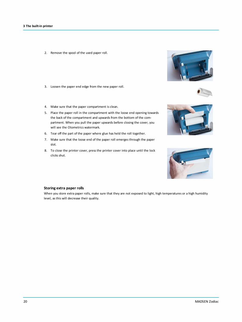
2. Remove the spool of the used paper roll.
3. Loosen the paper end edge from the new paper roll.
4. Make sure that the paper compartment is clean.
5. Place the paper roll in the compartment with the loose end opening towardsthe back of the compartment and upwards from the bottom of the com-partment. When you pull the paper upwards before closing the cover, youwill see the Otometrics watermark.
6. Tear off the part of the paper where glue has held the roll together.
7. Make sure that the loose end of the paper roll emerges through the paperslot.
8. To close the printer cover, press the printer cover into place until the lockclicks shut.
Storing extra paper rollsWhen you store extra paper rolls, make sure that they are not exposed to light, high temperatures or a high humiditylevel, as this will decrease their quality.
20 MADSEN Zodiac
3 The built-in printer

4 Views of ZodiacThis section provides you with views of MADSEN Zodiac.
• Front view► 21
• Bottom view► 22
Zodiac Stand-aloneYou will find a description of the front panel controls in MADSEN Zodiac test controls► 29
4.1 Front view
Stand-alone
A. DisplayB. On/off switchC. Front panelD. Dial (diagnostic/clinical version)
PC-based
A. On/off switchB. On/off indicator
MADSEN Zodiac 21
4 Views of Zodiac

4.2 Bottom view
A. Probe connectionsB. Label
22 MADSEN Zodiac
4 Views of Zodiac

5 The Zodiac probes
Warning• Inspect the patient's ear. Look into the ear canal. It is strongly recommended that you perform an oto-scopy to assess the status of the outer ear before you insert the probe. If the ear canal is blocked, this may affect theresult of the test. Clean the ear canal if needed. Make sure that there is no residual fluid in the patient's ear aftercleaning or ear wax removal.
Warning• If you have been testing on an infected ear canal, fit a new probe tip on the probe. Cleaning the probe ringmay also be necessary.
Hygienic precautions• Be sure to follow any established infection control procedures for the setting in which you are working.
• Always use clean eartips.
• To prevent cross-infection, use new eartips when you test the next client.
• Swab the probe tip with disinfectant before you test the other ear. If one ear is infected, test the healthy ear first andchange eartips before you test the other ear.
The immittance probesMADSEN Zodiac supports the following types of immittance probes:
• The Quick Check probe► 23
• The diagnostic probes► 25
At delivery, depending on the configuration of MADSEN Zodiac, one or both probes are already connected to the device.
The contralateral phoneMADSEN Zodiac supports the insert phone and supra-aural headphones listed in Technical specifications► 131.
• The contralateral phone► 27
Calibrating the immittance probesThe immittance probes are calibrated at delivery, but should be re-calibrated on a regular basis.
• Probe check► 37
• Probe admittance calibration► 118
5.1 The Quick Check probe
Depending on the configuration of MADSEN Zodiac, MADSEN Zodiac can be used with the Quick Check immittance probe.By using different eartips the probe can be used for both children and adults.
• The Zodiac Quick Check probe is optimized for fast, single-handed operation
If applicable, Zodiac is delivered with the Quick Check probe already connected.
MADSEN Zodiac 23
5 The Zodiac probes

A. Probe bodyB. Ear button
– Press this button to switch test ears
C. Light indicator showing the color of the selected testear and leakage status
Using the probe• Fitting the eartip on the probe► 39
• Cleaning the probe and probe tip► 122
Warning•Always fit an eartip on the probe before inserting it into the ear of the patient.
Warning•The eartip can be used for both ears. If you suspect infection in one ear, use a clean eartip and probe tipbefore you continue testing on the other ear.
Holding the probe
• Underhand grip
• Overhand grip
24 MADSEN Zodiac
5 The Zodiac probes

Starting the testThe test starts automatically when you press the screening eartip gently into the ear canal and seal is obtained.
Stopping the testYou can stop the test by removing the probe from the test ear.
Preparing and cleaning the probeSee
• Fitting the eartip on the probe► 39
• Cleaning the probe and probe tip► 122
5.2 The diagnostic probes
Depending on the configuration of MADSEN Zodiac, MADSEN Zodiac can be used with one or two types of immittanceprobes. By using different eartips the probes can be used for both children and adults.
• The Zodiac Quick Check probe is optimized for fast, single-handed operation
• The Zodiac diagnostic and clinical probe is optimized for reflex measurements, and combined with the use of a con-tralateral phone.
Depending on the configuration of the device,Zodiac Diagnostic and Zodiac Clinical are deliveredwith a diagnostic probe already connected.
The diagnostic probe is available in two versions.
The Classic probe The Comfort probe
Warning•Always fit an eartip on the probe before inserting it into the ear of the patient.
Using the probe• The diagnostic probe and shoulder strap► 25
• Using two probes with the device► 27
• Fitting the eartip on the probe► 39
• Fitting the probe in the patient’s ear► 40
• Cleaning the probe and probe tip► 122
5.2.1 The diagnostic probe and shoulder strap
The diagnostic probe is connected to the probeshoulder strap.
Warning•Always fit an eartip on the probebefore inserting it into the ear of the patient. The Classic probe The Comfort probe
MADSEN Zodiac 25
5 The Zodiac probes

The shoulder strap
The shoulder strap is a flexible strap designed to fit acrossthe shoulder of the patient. It ensures that the diagnosticprobe stays in place during testing so that measurementswill not be influenced by background noise.
A. Shoulder strapB. Hole for hanging shoulder strapC. Diagnostic probeD. Control padE. Contralateral phoneF. Probe cable connections
Probe cable connections
A. The diagnostic probe connectionThe diagnostic probe is permanently connected tothe control pad.
B. Connection cableThe connection cable connects the diagnostic probeto Zodiac.
C. Connection socket for the contralateral phoneWhen needed, connect the contralateral phone tothis socket.
26 MADSEN Zodiac
5 The Zodiac probes

The probe control pad
The control pad is part of the shoulder strap.
A. The light indicator shows the color of the selectedtest ear, and probe status
B. Ear button.– Press this button to switch test ears
C. Start/stop buttonPress this button to start or stop a test.
The diagnostic probe
A. The light indicator shows the color of the selectedtest ear, probe status, and leakage status
B. Probe bodyC. Probe ringD. Probe tip
5.2.2 Using two probes with the device
If your Zodiac is equipped with both a Quick Check and a diagnostic probe, you can easily switch between using the twoprobes:
• If the probe you wish to use is not activated, press any one of the buttons on the probe to activate it.
5.2.3 The contralateral phone
If you wish to test for the contralateral reflex, use the contralateral phone to present the stimulus to the non-probe ear.
Connecting the contralateral phone• When needed, connect the contralateral phone to
this socket on the control pad.
Push the plug firmly into the socket until it locks intothe socket.
Disconnecting the contralateral phone• To disconnect the contralateral phone, take hold of
the reinforced sleeve of the plug and pull firmly untilthe plug is disconnected.
MADSEN Zodiac 27
5 The Zodiac probes
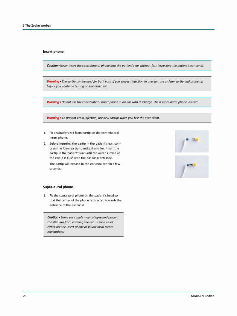
Insert phone
Caution•Never insert the contralateral phone into the patient's ear without first inspecting the patient's ear canal.
Warning•The eartip can be used for both ears. If you suspect infection in one ear, use a clean eartip and probe tipbefore you continue testing on the other ear.
Warning•Do not use the contralateral insert phone in an ear with discharge. Use a supra-aural phone instead.
Warning•To prevent cross-infection, use new eartips when you test the next client.
1. Fit a suitably sized foam eartip on the contralateralinsert phone.
2. Before inserting the eartip in the patient's ear, com-press the foam eartip to make it smaller. Insert theeartip in the patient's ear until the outer surface ofthe eartip is flush with the ear canal entrance.
The eartip will expand in the ear canal within a fewseconds.
Supra-aural phone
1. Fit the supra-aural phone on the patient's head sothat the center of the phone is directed towards theentrance of the ear canal.
Caution•Some ear canals may collapse and preventthe stimulus from entering the ear. In such caseseither use the insert phone or follow local recom-mendations.
28 MADSEN Zodiac
5 The Zodiac probes

6 MADSEN Zodiac test controls
6.1 The Quick Check front panel
A. Starting and ending a sessionB. Measurement selectionsC. Running testsD. On-screen selections
Depending on the configuration of the stand-alone version of Zodiac, the front panel has a range of function buttons, a dial,and three soft-buttons.
Starting and ending a session
New Session Press this button to create a new session.
Report The function of this button depends on the configuration of the system.
• Zodiac with a built-in printer:Press this button to print all test results for the current patient.
Measurement selections
Tymp
(tympanometry)
Press this button to select the Tympanometry test.
Reflex (Reflex Screening) Press this button to select the Reflex Screening test.
MADSEN Zodiac 29
6 MADSEN Zodiac test controls

Stimulus frequencies (Hz) Press these buttons to select the desired pure tone frequency for the reflexmeasurement.
You can choose between the following frequencies:
• 0.5 kHz
• 1 kHz
• 2 kHz
• 4 kHz
Noise (stimulus) Press this button to select Broadband noise as a reflex stimulus.
Ear This button is placed both on the device and on the probes.
Press this button to toggle the ear selection associated with the currentmeasurement.The button lights up in the color of the selected ear.
Delete Press this button to delete individual measurements.
Probe check
Probe check Place the probe in the probe check cavity and press this button to carry outa probe check.
On-screen selections
Soft-button Press this button to select the current function of the soft-button as shownon the screen just above the soft-button.
• Menu:Press the soft-button below the column you wish to go to.
• Tympanometry:Press to toggle between tympanometric curves and to change curvetype.
Menu Press this button to display the menu where you can select test setups,change test settings, create user tests, select print output, and select func-tions for service and calibration.
30 MADSEN Zodiac
6 MADSEN Zodiac test controls

On-screen selections
Arrow Up This function is enabled when you activate the Menu function
• Press this button until you highlight the desired area on the screen.
Arrow Down This function is enabled when you activate the Menu function.
• Press this button until you highlight the desired area on the screen.
6.2 The Diagnostic and Clinical front panel
A. Starting and ending a sessionB. Measurement selectionsC. Running testsD. On-screen selections
Depending on the configuration of the stand-alone version of Zodiac, the front panel has a range of function buttons, a dial,and three soft-buttons.
Starting and ending a session
New Session Press this button to create a new session.
Report The function of this button depends on the configuration of the system.
• Zodiac with a built-in printer:Press this button to print all test results for the current patient.
Measurement selections
Tymp
(tympanometry)
Press this button to select the Tympanometry test.
MADSEN Zodiac 31
6 MADSEN Zodiac test controls

Ipsi (ipsilateral) Press to select the presentation side for reflex testing (the probe ear).
Contra (contralateral) Press to select the presentation side for reflex testing (the non-probe ear).
Stimulus frequencies (Hz) Press these buttons to select the desired pure tone frequency for the reflexmeasurement.
You can choose between the following frequencies:
• 0.5 kHz
• 1 kHz
• 2 kHz
• 4 kHz
Noise (stimulus) Press this button to select Broadband noise as a reflex stimulus.
±P (pressure offset) Press this button to select a pressure offset to stabilize the eardrum. Thismay facilitate reflex recordings from ears that have steeply sloped tym-panograms. Keep the button depressed and use the dial to select thedesired pressure.
The function of this button is described in-depth in the Reference Manual.
Special (special tests) Press this button to select special tests.
32 MADSEN Zodiac
6 MADSEN Zodiac test controls

Sequence testing
Seq. (automatic sequencetesting)
This function allows you to combine multiple measurements and run themin an automated sequence.
Press this button to select automatic sequence testing. The buttons cor-responding to the tests and test functions included in the sequence light upon the device, e.g. Tympanometry + Ipsi and Contra Reflex Thresholds atseveral frequencies.
When you press the Start/Stop button, all functions that have been selec-ted for the sequence are performed.
You can adjust any settings related to the tests included in the sequence.
Diagnostic sequenceTympanometry + Reflex Threshold (+ Reflex Decay, if selected from the Set-tings menu).
Screening sequenceTympanometry + Reflex Screening.
Running tests
Start/Stop This button is placed both on the device and on the diagnostic probeshoulder strap.
This button is lit while a test is running.
• Press this button to perform a tympanometric measurement, to startreflex tests, and to present stimuli for manual reflex testing.
• During a test, press this button to stop the test.
Auto-startPress this button to activate Auto start on seal before you place the probein the patient's ear.
This button is disabled when you use the Quick Check probe, which alwaysuses Auto start on seal.
Dial Turn the dial to adjust pump pressure and to control the stimulus level.
Ear This button is located both on the device and on the probes.
Press this button to toggle the ear selection associated with the currentmeasurement.The button lights up in the color of the selected ear.
Delete Press this button to delete the selected measurement curve.
MADSEN Zodiac 33
6 MADSEN Zodiac test controls
On-screen selections
Soft-button Press this button to select the current function of the soft-button as shownon the screen just above the soft-button.
• Menu:Press the soft-button below the column you wish to go to.
• Tympanometry:Press to toggle between tympanometric curves and to change curvetype.
Menu Press this button to display the menu where you can select test setups,change test settings, create user tests, select print output, and select func-tions for service and calibration.
Arrow Up This function is enabled when you activate the Menu function
• Press this button until you highlight the desired area on the screen.
Arrow Down This function is enabled when you activate the Menu function.
• Press this button until you highlight the desired area on the screen.
Dial In addition to the various measurement functions, you can use the dial toscroll between menu items on the screen.
6.3 The Zodiac menu
If you use a stand-alone version of Zodiac, you can use the function-specific buttons to activate the most commonly usedfunctions for testing, changing test settings, and managing test results.
If you need to make further changes to a test setup, or other more specific functions, pressMenu or Special for morechoices.
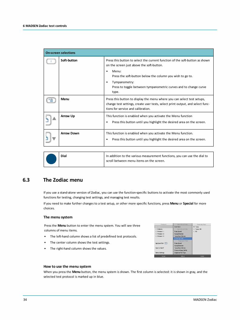
The menu system
Press the Menu button to enter the menu system. You will see threecolumns of menu items.
• The left-hand column shows a list of predefined test protocols.
• The center column shows the test settings.
• The right-hand column shows the values.
How to use the menu systemWhen you press the Menu button, the menu system is shown. The first column is selected: it is shown in gray, and theselected test protocol is marked up in blue.
34 MADSEN Zodiac
6 MADSEN Zodiac test controls

• Use the arrow buttons to scroll up or down to select another test protocol, if needed.
• Use the dial or the arrow buttons to select another test protocol, if needed.
• Press the soft-button below the next column to select this column, and scroll to any setting you wish to view orchange.
How to change test settings1. Start by selecting a protocol.
2. Select the center column.
3. Scroll to the setting you wish to view or change.
4. Select the right-hand column to change the setting.
5. Scroll to the value you wish to use and press the Select soft-button.
6. Repeat steps 2 to 5 to change other settings, if needed.
Using test settings temporarily• If you only wish to use the changed protocol settings temporarily, select the left-hand column, scroll to Apply Tem-
porarily and press the OK soft-button. This will exit the menu system.
Saving test settings in the protocolBefore you can save test settings in the protocol, you must unlock the protocol: Select Device Settings.. > Protocol Set-tings, and set to Allowed. If you switch off Zodiac after changing and saving the test settings, the protocol will be lockedagain.
• If you wish to save the changed protocol settings permanently, select the left-hand column, scroll to Save to [Protocolname], and press the Save soft-button.
Canceling changed test settings• If you wish to cancel the settings you have changed, select the protocol and press the Reload soft-button.
6.4 Special tests
The Diagnostic and Clinical versions of Zodiac can perform a number of special immittance tests, such as ETF-P and ManualTympanometry.
Accessing special testsWhen you press the Special button, the available tests are shown.
You can access the Probe Check function from the Special Tests menu.
Loading a special test
1. Press the Special button.
2. Scroll to select the special test you wish to use.
3. Press the OK soft-button.
MADSEN Zodiac 35
6 MADSEN Zodiac test controls

Exiting a special test
Press the Special button to exit the special test. Zodiac returns to Tympanometry mode.
Exiting the Special Tests menu• Press the Cancel soft-button to exit the Special Tests menu. Zodiac returns to Tympanometry mode.
36 MADSEN Zodiac
6 MADSEN Zodiac test controls

7 Preparing for testingIn order for you to save time for both you and the client, we recommend that you prepare the environment, the client,the test device setup and the Otosuite software so that they are ready for the test.
To prepare for testing:• If this is the first test of the day, make a probe check. See Probe check► 37.
• If needed, connect the contralateral phone. See The contralateral phone► 27.
• Prepare MADSEN Zodiac and the Immittance module: select the patient and test setup. See the Otosuite User Guide.
• Prepare the patient. See Inspecting the patient’s ear► 39.
• Prepare probe and eartip. See Fitting the eartip on the probe► 39 and Fitting the probe in the patient’s ear► 40.
7.1 Preparing the test environment
Immittance tests require no specific test environment with regard to noise.
7.2 Hygienic precautions
• Be sure to follow any established infection control procedures for the setting in which you are working.
• Always use clean eartips.
• Swab the probe tip with disinfectant between ears. If one ear is infected, test the healthy ear first and change eartipsbetween ears.
• To prevent cross-infection, use a clean eartip when you test the next patient.
7.3 Probe check
To make sure that the probe is functioning correctly, it is recommended that you perform a probe check at the start ofeach day.
Caution•Always clean and disinfect the probe tip before you insert it into a test cavity.
See Cleaning the probe and probe tip► 122.
Note • If the test environment changes, for instance if there is an increase in humidity or if you are going to test at adifferent altitude, make a probe check to verify that the system measures correctly.
Note • If the probe check result does not show a value of 1.9 - 2.1 mmho/cc/ml at 226 Hz, we recommend that youmake an admittance calibration. See Probe admittance calibration► 118.
MADSEN Zodiac 37
7 Preparing for testing

1. Use a new probe tip, or make sure that the probe tip has been cleaned and dis-infected, before you place it in the test cavity. This is to make sure that theprobe tip does not influence the probe test, and that the test cavity is not con-taminated.
2. Insert the probe tip without eartip in the 2 cc test cavity.
3. Select the probe check function:
From Zodiac Quick Check - Stand-alone:
– Press the Probe Check button.
You may have to support the probe in the test cavity.
From Zodiac Diagnostic and Clinical - Stand-alone:
– Press the Special button and select Probe check.
From Otosuite:
– Click the Probe check icon on the toolbar.
The probe check starts automatically. If it does not, press the Start button tostart the check. If it does not, click the Start button to start the check.
The probe is checked for occlusion and leakage. If the probe check result showsa value of 1.9 - 2.1 mmho/cc/ml at 226 Hz, the probe is OK. If not, we recom-mend that you make an admittance calibration.
Additional probe admittance checks can be performed. See the MADSENZodiac Reference Manual.
If there is a probe errorIn case of a probe error, the probe may be occluded or faulty.
• If the probe is occluded, clean or replace the probe tip.
• If the probe is faulty, contact an authorized service department for repair.
7.4 Creating a new session
When you wish to test a new patient, create a new session. This will clear the device memory of old data.
When Zodiac is not connected to Otosuite
• When you have finished testing a patient and wish to start testing a new patient, press the New Sessionbutton.
When Zodiac is connected to Otosuite• Create a new session in Otosuite.
38 MADSEN Zodiac
7 Preparing for testing

• When you wish to test a new patient, click to open the Client Details window and click New Session.
This will close the current patient data set and make it possible for you to save data under a new patient.
7.5 Using a test setup
In ZodiacEvery time you create a new session in Zodiac, shortcuts to your favorite test setups will be shown on the screen. Use thesoft-buttons to select the test setup you prefer. These test setup short-cuts are shown until you start the measurements.
Selecting a test setup from the menuYou can select a test setup different from the one currently selected.
1. Press the Menu button.
2. Use the arrow buttons to navigate to the desired test setup.
3. Press the Menu button to exit the menu. The selected test setupwill be used for testing.
Editing a test setupTo change the settings in a test setup, see The Zodiac menu► 34.
In OtosuiteYou can select a test setup different from the one currently selected.
• Click to open the Test Selector window. This window enables you to load user defined tests, special testsetups, and factory default tests.
7.6 Inspecting the patient’s ear
1. Position the patient so that you can easily access the ear to be tested.
2. Grasp the pinna and gently pull back and slightly away from the patient's head.
Note • If the patient is a newborn, gently pull the pinna down and back. For older infants, pull the pinna up andback.
3. Look into the ear canal. It is strongly recommended that you perform an otoscopy to assess the status of the outer earbefore you insert the probe.
4. If the ear canal is blocked, this may affect the result of the test. Clean the ear canal if needed.
7.7 Fitting the eartip on the probe
You can choose between various types of eartips, depending on the type of test you wish to do:
MADSEN Zodiac 39
7 Preparing for testing

• Screening eartips
• Regular eartips
• Infant eartips
Warning•Choking hazard! Do not leave eartips unsupervised within the reach of children.
Note •Accurate testing is only guaranteed if you use the eartips approved specifically for MADSEN Zodiac by Oto-metrics.
Note •Check the sound channels in the probe tip every time you have used the probe.Even small amounts of cerumenor vernix can block the sound channels. Clean the sound channels if needed.
Warning•The eartip can be used for both ears. If you suspect infection in one ear, exchange the eartip and clean theprobe tip before you continue testing on the other ear.
The Quick Check probe• We recommend that you use an oversized eartip with the Quick Check probe.
The diagnostic probeFit the eartip on the probe.
1. Firmly push and twist the eartip onto the probe tip, until it rests firmly against the base of the probe tip.
Removing the eartip• To remove the eartip, grasp the stem of the eartip and pull the eartip straight off the probe tip.
7.8 Fitting the probe in the patient’s ear
In the following you will find procedures for
• fitting a diagnostic probe with a regular eartip in the patient's ear, and
• applying the Quick Check probe with a screening eartip against the ear canal opening of the patient.
General use1. Look into the ear canal. It is strongly recommended that you perform an otoscopy to assess the status of the outer ear
before you insert the probe.
40 MADSEN Zodiac
7 Preparing for testing

2. If the ear canal is blocked, this may affect the result of the test. Clean the ear canal if needed.
Caution•The probe can be damaged if fluids enter the probe.
Warning•Always fit the probe with a new eartip when you place the probe in the ear canal of a new patient.
Warning•The eartip can be used for both ears. If you suspect infection in one ear, use a clean eartip and probe tipbefore you continue testing on the other ear.
Caution•Avoid excessive force when you place the ear tip against the ear canal opening of the patient as this maycause unnecessary discomfort, particularly if the eartip is small enough to enter the ear canal.
Caution•Always use a suitably sized eartip. Using a probe with an unsuitably sized eartip or applying excessive forcemay cause unnecessary discomfort to the patient.
Premature babies, newborns and infants
Warning•Be careful not to insert the probe too far into the ear canal of premature babies and newborns.
Note •Because infants’ ear canals are very soft, they are easily pressed out of shape.If this happens, wait until the ear canal returns to its original shape. Release the pinna and try again. Gently mas-saging the area may help opening the ear canal.
Fit the probe in the ear
1. With a hand-held probe you can use a slightly over-sized eartip in order to achieve a seal when usedwith a wider range of ear canal sizes.
The oversized eartip is not intended to enter theear canal.
2. Fit the eartip on the probe.
MADSEN Zodiac 41
7 Preparing for testing
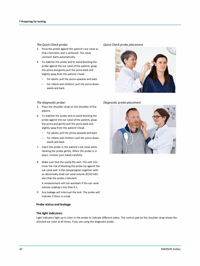
The Quick Check probe:3. Press the probe against the patient's ear canal so
that a hermetic seal is achieved. The meas-urement starts automatically.
4. To stabilize the probe and to avoid blocking theprobe against the ear canal of the patient, graspthe pinna and gently pull the pinna back andslightly away from the patient's head.
– For adults: pull the pinna upwards and back.
– For infants and children: pull the pinna down-wards and back.
Quick Check probe placement
The diagnostic probe:5. Place the shoulder strap on the shoulder of the
patient.
6. To stabilize the probe and to avoid blocking theprobe against the ear canal of the patient, graspthe pinna and gently pull the pinna back andslightly away from the patient's head.
– For adults: pull the pinna upwards and back.
– For infants and children: pull the pinna down-wards and back.
7. Insert the probe in the patient's ear canal whiletwisting the probe gently. When the probe is inplace, remove your hands carefully.
Diagnostic probe placement
8. Make sure that the eartip fits well. This will min-imize the risk of blocking the probe tip against theear canal wall. A flat tympanogram together withan abnormally small ear canal volume (ECV) indic-ates that the probe is blocked.
A measurement will not autostart if the ear canalvolume reading is less than 0.1.
9. Any leakage will interrupt the test. The probe willindicate if there is a leak.
Probe status and leakage
The light indicatorsLight indicators light up in color in the probe to indicate different states. The control pad on the shoulder strap shows theselected ear color at all times, if you are using the diagnostic probe.
42 MADSEN Zodiac
7 Preparing for testing

Probe color Status
Red • The right test ear has been selected
• The device is in idle mode
Blue • The left test ear has been selected
• The device is in idle mode
Green • The test is running
Yellow • Leak
Probe leakage
Stand-aloneIf there is a probe leak during testing, this will be shown on the MADSEN Zodiac and Otosuite screens.
PC-basedIf there is a probe leak during testing, this will be shown on the Otosuite screen.
If you are using the Quick Check probe, the leakage indication will remain until you remove the probefrom the ear and try again.
Probe blocked
Stand-aloneIf the probe is blocked during testing, this will be shown on the MADSEN Zodiac and Otosuite screens.
PC-basedIf the probe is blocked during testing, this will be shown on the Otosuite screen.
If you are using the Quick Check probe, the blocked probe indication will remain until you remove theprobe from the ear and try again.
MADSEN Zodiac 43
7 Preparing for testing

8 Testing with Zodiac Quick Check - Stand-Alone
Note •The safety intensity level cannot be exceeded in screening mode.
MADSEN Zodiac Quick Check performs automatic 226 Hz tym-panometry which can be combined with Ipsi Reflex testing.
All tests are performed in one single sequence.
MADSEN Zodiac is used in combination with the hand-heldQuick Check probe fitted with an eartip.
The measurements are performed automatically when theprobe is pressed gently against the patient's ear canal and her-metic seal is achieved.
8.1 Starting a measurement
To prepare for the test before you start testing, see Preparing for testing► 37.
1. Look into the ear canal. It is strongly recommended that you perform an otoscopy to assess the status of the outer earbefore you insert the probe.
2. If the ear canal is blocked, this may affect the result of the test. Clean the ear canal if needed.
Caution•The probe can be damaged if fluids enter the probe.
Warning•Always fit the probe with a new eartip when you place the probe in the ear canal of a new patient.
Warning•The eartip can be used for both ears. If you suspect infection in one ear, use a clean eartip and probe tipbefore you continue testing on the other ear.
Caution•Avoid excessive force when you place the ear tip against the ear canal opening of the patient as this maycause unnecessary discomfort, particularly if the eartip is small enough to enter the ear canal.
Fit the probe in the ear
1. With a hand-held probe you can use a slightly over-sized eartip in order to achieve a seal when usedwith a wider range of ear canal sizes.
The oversized eartip is not intended to enter theear canal.
2. Fit the eartip on the probe.
44 MADSEN Zodiac
8 Testing with Zodiac Quick Check - Stand-Alone

3. Ask the patient to sit very still and quiet duringthe test, without moving head or jaw.
The Quick Check probe:4. Press the probe against the patient's ear canal so
that a hermetic seal is achieved. The meas-urement starts automatically.
5. To stabilize the probe and to avoid blocking theprobe against the ear canal of the patient, graspthe pinna and gently pull the pinna back andslightly away from the patient's head.
– For adults: pull the pinna upwards and back.
– For infants and children: pull the pinna down-wards and back.
Quick Check probe placement
6. A flat tympanogram together with an abnormallysmall ear canal volume (ECV) indicates that theprobe is blocked
7. Any leakage will interrupt the test. The probe willindicate if there is a leak.
When you get a leak detection signal, you mustbriefly remove the probe from the ear before try-ing again.
8. Make sure that the eartip fits well. This will min-imize the risk of blocking the probe tip against theear canal wall. A flat tympanogram together withan abnormally small ear canal volume (ECV) indic-ates that the probe is blocked.
A measurement will not autostart if the ear canalvolume reading is less than 0.1.
9. Any leakage will interrupt the test. The probe willindicate if there is a leak.
Probe status and leakage
The light indicatorsLight indicators light up in color in the probe to indicate different states. The control pad on the shoulder strap shows theselected ear color at all times, if you are using the diagnostic probe.
MADSEN Zodiac 45
8 Testing with Zodiac Quick Check - Stand-Alone

Probe color Status
Red • The right test ear has been selected
• The device is in idle mode
Blue • The left test ear has been selected
• The device is in idle mode
Green • The test is running
Yellow • Leak
Otosuite indications
Color Status
Green • During measurements, Otosuite shows a green background to the onlinevalues.
Probe leakage
Stand-aloneIf there is a probe leak during testing, this will be shown on the MADSEN Zodiac and Otosuite screens.
PC-basedIf there is a probe leak during testing, this will be shown on the Otosuite screen.
If you are using the Quick Check probe, the leakage indication will remain until you remove the probefrom the ear and try again.
Probe blocked
Stand-aloneIf the probe is blocked during testing, this will be shown on the MADSEN Zodiac and Otosuite screens.
PC-basedIf the probe is blocked during testing, this will be shown on the Otosuite screen.
If you are using the Quick Check probe, the blocked probe indication will remain until you remove theprobe from the ear and try again.
8.2 The Quick Check measurement screen
When the measurement starts, you will see the measurement being performed real-time on the screen.
46 MADSEN Zodiac
8 Testing with Zodiac Quick Check - Stand-Alone

A. On-line valuesB. Tympanometry graphC. Reflex Screening resultsD. Tympanometry resultsE. On-screen selections
A. On-line values
The on-line values show the current settings and status.
• Probe tone in Hz
• Pump speed
• Sweep direction
• Current equivalent volume/admittance (678, 800, 1000 Hz probe tone)
B. Tympanometry graph
The graph area shows the tympanometric curves and can rescale automatically to fit the curves.
• Tympanometric curves
• Pressure and admittance scales
• Ear canal volume bar. The ear canal volume is shown to the right of the graph.
• Norm area
C. Reflex Screening results
The detected reflex is shown in the results area.
• Stimulus type level
• Progress indicator during measurements
• Deflection curves are shown when a reflex has been detected.
If a reflex is not detected, the highest stimulus is displayed together with aNo Response indication.
If the system cannot automatically analyze a reflex measurement, aNot Tested indication is shown.
MADSEN Zodiac 47
8 Testing with Zodiac Quick Check - Stand-Alone

D. Tympanometry results
The results table shows the results related to the currently selected curve:
• Probe (the probe tone in Hz)
• TPP (Tympanometric Peak Pressure)
• ECV (Equivalent Ear Canal Volume)
• SA (Static Peak Admittance), or SC (Static Peak Compliance) when volume equivalent units are used
• TW/Ratio (Tympanometric Width/Tympanometric Ratio). Describes the steepness of the curve.
• Type (Jerger types A, As, Ad, B, C, D and E denote the shape of the 226 Hz curve). You can set the type to bedetermined automatically, and you can subsequently change it manually, if necessary.
E. On-screen selections
Curve selection Press the Previous Curve or Next Curve softbutton to select the desired curve inthe Reflex Screening and Tympanometry result tables.
Manually adjusting the TPP Press the Edit TPP softbutton, use the dial to move the marker to the desiredTPP, and press the Done softbutton.
Changing tympanogram curve type Press the Edit TPP softbutton. Press the Change Type softbutton until thedesired type is shown, and press the Done softbutton.
Deleting a curve Select the curve you wish to delete, and press the Delete button.
To replace a single measurement, delete a curve and adjust the measurementselections to redo the single measurement.
48 MADSEN Zodiac
8 Testing with Zodiac Quick Check - Stand-Alone

9 Testing with Zodiac Diagnostic or Clinical -Stand-Alone
Zodiac Diagnostic or Clinical performs tympanometry whichcan be combined with diagnostic reflex tests such as thresholdand decay measurements .
These measurements can be performed manually, auto-matically or in a sequence of tests with the option of using mul-tiple probe tones.
An additional range of features is described in detail in theMADSEN Zodiac Reference Manual.
Zodiac has two probe connections which make it possible tochoose between using a Quick Check probe for fast tym-panometry, and a diagnostic probe for more detailed meas-urements.
9.1 Quick Check testing
You can perform Tympanometry + Reflex Screening as a sequence from the Tympanometry test screen.
When seal is obtained, i.e. when the screening eartip is pressed gently against the ear, the test starts with tympanometrytesting and continues automatically from tympanometry to reflex screening.
Note •The safety intensity level cannot be exceeded in screening mode.
Note •You can use either ordinary eartips or screening eartips for screening.
Preparing for testing1. Do as described in Preparing for testing► 37.
2. Ask the patient to sit very still and quiet during the test, without moving head or jaw.
3. If needed, toggle the Ear Selector to select the ear on which you wish to start the test.
4. Continue as described in Starting a measurement► 49.
9.1.1 Starting a measurement
To prepare for the test before you start testing, see Preparing for testing► 37.
1. Look into the ear canal. It is strongly recommended that you perform an otoscopy to assess the status of the outer earbefore you insert the probe.
2. If the ear canal is blocked, this may affect the result of the test. Clean the ear canal if needed.
MADSEN Zodiac 49
9 Testing with Zodiac Diagnostic or Clinical - Stand-Alone

Caution•The probe can be damaged if fluids enter the probe.
Warning•Always fit the probe with a new eartip when you place the probe in the ear canal of a new patient.
Warning•The eartip can be used for both ears. If you suspect infection in one ear, use a clean eartip and probe tipbefore you continue testing on the other ear.
Caution•Avoid excessive force when you place the ear tip against the ear canal opening of the patient as this maycause unnecessary discomfort, particularly if the eartip is small enough to enter the ear canal.
Fit the probe in the ear
1. With a hand-held probe you can use a slightly over-sized eartip in order to achieve a seal when usedwith a wider range of ear canal sizes.
The oversized eartip is not intended to enter theear canal.
2. Fit the eartip on the probe.
3. Ask the patient to sit very still and quiet duringthe test, without moving head or jaw.
The Quick Check probe:4. Press the probe against the patient's ear canal so
that a hermetic seal is achieved. The meas-urement starts automatically.
5. To stabilize the probe and to avoid blocking theprobe against the ear canal of the patient, graspthe pinna and gently pull the pinna back andslightly away from the patient's head.
– For adults: pull the pinna upwards and back.
– For infants and children: pull the pinna down-wards and back.
Quick Check probe placement
50 MADSEN Zodiac
9 Testing with Zodiac Diagnostic or Clinical - Stand-Alone

6. A flat tympanogram together with an abnormallysmall ear canal volume (ECV) indicates that theprobe is blocked
7. Any leakage will interrupt the test. The probe willindicate if there is a leak.
When you get a leak detection signal, you mustbriefly remove the probe from the ear before try-ing again.
8. Make sure that the eartip fits well. This will min-imize the risk of blocking the probe tip against theear canal wall. A flat tympanogram together withan abnormally small ear canal volume (ECV) indic-ates that the probe is blocked.
A measurement will not autostart if the ear canalvolume reading is less than 0.1.
9. Any leakage will interrupt the test. The probe willindicate if there is a leak.
Probe status and leakage
The light indicatorsLight indicators light up in color in the probe to indicate different states. The control pad on the shoulder strap shows theselected ear color at all times, if you are using the diagnostic probe.
Probe color Status
Red • The right test ear has been selected
• The device is in idle mode
Blue • The left test ear has been selected
• The device is in idle mode
Green • The test is running
Yellow • Leak
Otosuite indications
Color Status
Green • During measurements, Otosuite shows a green background to the onlinevalues.
MADSEN Zodiac 51
9 Testing with Zodiac Diagnostic or Clinical - Stand-Alone

Probe leakage
Stand-aloneIf there is a probe leak during testing, this will be shown on the MADSEN Zodiac and Otosuite screens.
PC-basedIf there is a probe leak during testing, this will be shown on the Otosuite screen.
If you are using the Quick Check probe, the leakage indication will remain until you remove the probefrom the ear and try again.
Probe blocked
Stand-aloneIf the probe is blocked during testing, this will be shown on the MADSEN Zodiac and Otosuite screens.
PC-basedIf the probe is blocked during testing, this will be shown on the Otosuite screen.
If you are using the Quick Check probe, the blocked probe indication will remain until you remove theprobe from the ear and try again.
9.1.2 The Quick Check measurement screen
When the measurement starts, you will see the measurement being performed real-time on the screen.
A. On-line valuesB. Tympanometry graphC. Reflex Screening resultsD. Tympanometry resultsE. On-screen selections
A. On-line values
The on-line values show the current settings and status.
• Probe tone in Hz
• Pump speed
• Sweep direction
• Current equivalent volume/admittance (678, 800, 1000 Hz probe tone)
52 MADSEN Zodiac
9 Testing with Zodiac Diagnostic or Clinical - Stand-Alone

B. Tympanometry graph
The graph area shows the tympanometric curves and can rescale automatically to fit the curves.
• Tympanometric curves
• Pressure and admittance scales
• Ear canal volume bar. The ear canal volume is shown to the right of the graph.
• Norm area
C. Reflex Screening results
The detected reflex is shown in the results area.
• Stimulus type level
• Progress indicator during measurements
• Deflection curves are shown when a reflex has been detected.
If a reflex is not detected, the highest stimulus is displayed together with aNo Response indication.
If the system cannot automatically analyze a reflex measurement, aNot Tested indication is shown.
D. Tympanometry results
The results table shows the results related to the currently selected curve:
• Probe (the probe tone in Hz)
• TPP (Tympanometric Peak Pressure)
• ECV (Equivalent Ear Canal Volume)
• SA (Static Peak Admittance), or SC (Static Peak Compliance) when volume equivalent units are used
• TW/Ratio (Tympanometric Width/Tympanometric Ratio). Describes the steepness of the curve.
• Type (Jerger types A, As, Ad, B, C, D and E denote the shape of the 226 Hz curve). You can set the type to bedetermined automatically, and you can subsequently change it manually, if necessary.
E. On-screen selections
Curve selection Press the Previous Curve or Next Curve softbutton to select the desired curve inthe Reflex Screening and Tympanometry result tables.
Manually adjusting the TPP Press the Edit TPP softbutton, use the dial to move the marker to the desiredTPP, and press the Done softbutton.
Changing tympanogram curve type Press the Edit TPP softbutton. Press the Change Type softbutton until thedesired type is shown, and press the Done softbutton.
Deleting a curve Select the curve you wish to delete, and press the Delete button.
To replace a single measurement, delete a curve and adjust the measurementselections to redo the single measurement.
MADSEN Zodiac 53
9 Testing with Zodiac Diagnostic or Clinical - Stand-Alone

9.2 Sequence testing
A test sequence is a predefined set of automatic tests which can be performed automatically.
You can perform the immittance tests in a sequence:
• Diagnostic sequenceTympanometry + Reflex Threshold (auto search) (+ Reflex Decay, if selected from the menu).
• Screening sequenceTympanometry + Reflex Screening.
Zodiac will always perform the most recently selected sequence, either as settings loaded from start-up, as a user test, oras selected on the buttons on the device.
9.2.1 Selecting a test sequence
If the sequence selection is not enabled in the device, and a sequence is started from Otosuite, then the Otosuitesequence will remain enabled in MADSEN Zodiac until changed on the device.
Activating sequencemode1. Press the Seq. button.
2. The measurements that are included in the current test sequence light upon the measurement settings buttons, e.g. Tymp, Ipsi, Contra, 0.5k, 1k, 2k,etc. You can make any changes needed by pressing these buttons.
Adding a test to the sequence1. You can add Reflex Decay to the sequence: Press the Menu button and
select Sequence Settings > Sequence Tests > . The display will indicatewhich measurements are included in the sequence.
9.2.2 Running a test sequence
Starting a sequence1. Press the Start/Stop button.
Stopping a sequenceIf a leak is detected or the probe is removed from the patient’s ear, thesequence stops automatically.
1. To stop the test manually, press the Start/Stop button.
2. If the patient is troubled by the test, press the Start/Stop button to stop thetest. The test is interrupted and the pump pressure is relieved immediately.
Already measured results are kept when a measurement is stopped.
Alternatively, you can pause the test by pressing the Pause softbutton, andresume the test without running the entire test again.
54 MADSEN Zodiac
9 Testing with Zodiac Diagnostic or Clinical - Stand-Alone

Performing supplementary measurementsYou can always supplement the results, if needed. For example, if you need a supplementary threshold search, you canchange the sequence setup by deselecting the measurements that have already been made satisfactorily, and run a sup-plementary sequence. Alternatively, you can supplement a sequence with manually performed reflex measurements.
9.3 Tympanometry testing
Note • It is recommended that you perform a tympanometric test before making any acoustic reflex measurement,and determine the acoustic reflex threshold before making a reflex decay measurement.
You can record a tympanogram either as a separate measurement or as part of a diagnostic or screening sequence. In asequence, tympanometry is automatically followed by reflex testing.
In the following you will find the description for performing tympanometry as a single test. This means that the sequencefunction is not enabled.
The default setup available in the tympanometry test is designed for any of the tympanometry tests you canperform. Adjust the settings to suit your purposes.
Preparing for testing1. Do as described in Preparing for testing► 37.
2. If contralateral stimulation is used in the test, make sure that both the ipsilateral probe and the contralateral phoneare in place before you start the measurement.
3. Ask the patient to sit very still and quiet during the test, without moving head or jaw.
4. If needed, toggle the Ear Selector to select the ear on which you wish to start the test.
Activating the probeIf the probe is not activated (the probe light is not lit), activate the probe:
• The diagnostic probe: Press the Ear button on Zodiac or the Start/Stopbutton on the control pad.
• The Quick Check probe: Press the Ear button on the probe.
The probe lights up in the ear color to indicate that it is activated.
MADSEN Zodiac 55
9 Testing with Zodiac Diagnostic or Clinical - Stand-Alone

Starting the test1. Press the Tymp button. Make sure that only the Tymp button is selec-
ted.
2. Place the probe in the patient’s ear.
3. Ask the patient to sit very still and quiet during the test, without movinghead or jaw.
Quick Check probe:
– The test starts automatically when seal is achieved in the ear canal.
Diagnostic probe:
– Press the Start/Stop button on the device or the Start/Stop buttonon the probe control pad on the shoulder strap.
With the diagnostic probe you can also use automatic start: Pressthe Start/Stop button before placing the probe in the patient’s ear.
The test progresses as follows:
– The pump increases the pressure to the set value, and the sweep starts.
– The admittance for each pressure point is plotted out on the screen and forms the tympanogram curve.
Stopping the test1. If the patient is troubled by the test, press the Start/Stop button on the
device or the Start/Stop button on the probe control pad on theshoulder strap.
2. The test is interrupted and the pump pressure is relieved immediately.
Already measured results are kept when a measurement is stopped.
Making additional tympanograms1. To make a new sweep, press the Start/Stop button.
If you wish to overwrite a tympanogram, use the dial or the soft-buttons Previous Curve or Next Curve to select thecurve you wish to overwrite.
When you have finished testing one ear, switch ears, if needed.
Viewing and managing test results2. To view tympanometry results, see The Tympanometry screen► 57.
56 MADSEN Zodiac
9 Testing with Zodiac Diagnostic or Clinical - Stand-Alone

3. When you have finished testing, see Managing test results in MADSEN Zodiac► 113.
9.3.1 The Tympanometry screen
A. On-line valuesB. Tympanometry graphC. Reflex Screening resultsD. Tympanometry resultsE. On-screen selections
A. On-line values
The on-line values show the current settings and status.
• Probe tone in Hz
• Pump speed
• Sweep direction
• Current equivalent volume/admittance (678, 800, 1000 Hz probe tone)
B. Tympanometry graph
The graph area shows the tympanometric curves and can rescale automatically to fit the curves.
• Tympanometric curves
• Pressure and admittance scales
• Ear canal volume bar. The ear canal volume is shown to the right of the graph.
• Norm area
C. Reflex Screening results
The detected reflex is shown in the results area.
• Stimulus type level
• Progress indicator during measurements
• Deflection curves are shown when a reflex has been detected.
If a reflex is not detected, the highest stimulus is displayed together with aNo Response indication.
If the system cannot automatically analyze a reflex measurement, aNot Tested indication is shown.
MADSEN Zodiac 57
9 Testing with Zodiac Diagnostic or Clinical - Stand-Alone

D. Tympanometry results
The results table shows the results related to the currently selected curve:
• Probe (the probe tone in Hz)
• TPP (Tympanometric Peak Pressure)
• ECV (Equivalent Ear Canal Volume)
• SA (Static Peak Admittance), or SC (Static Peak Compliance) when volume equivalent units are used
• TW/Ratio (Tympanometric Width/Tympanometric Ratio). Describes the steepness of the curve.
• Type (Jerger types A, As, Ad, B, C, D and E denote the shape of the 226 Hz curve). You can set the type to bedetermined automatically, and you can subsequently change it manually, if necessary.
E. On-screen selections
Curve selection Press the Previous Curve or Next Curve softbutton to select the desired curve inthe Reflex Screening and Tympanometry result tables.
Manually adjusting the TPP Press the Edit TPP softbutton, use the dial to move the marker to the desiredTPP, and press the Done softbutton.
Changing tympanogram curve type Press the Edit TPP softbutton. Press the Change Type softbutton until thedesired type is shown, and press the Done softbutton.
Deleting a curve Select the curve you wish to delete, and press the Delete button.
To replace a single measurement, delete a curve and adjust the measurementselections to redo the single measurement.
58 MADSEN Zodiac
9 Testing with Zodiac Diagnostic or Clinical - Stand-Alone

Results shown
The results are shown as a tympanometric curve traced overthe norm area (if Norm Area is enabled).
The tympanogram can be viewed in four different ways:
• traditional absolute admittance, Y
• traditional baseline compensated admittance, Ytm
• susceptance, B, and conductance, G; both absolute andcompensated
• component compensated admittance, Ytm
Note •The probe tone shown at the top of the test screenapplies to the currently selected measurement setting,and may not reflect the probe tone setting that was usedfor the curve shown.
The actual probe tone applying to the curve shown is shown inthe results table.
9.4 ETF-I (Eustachian Tube Function - Intact) testing
Note •This test is available only if MADSEN Zodiac supports diagnostic testing.
Procedure
All three result rows in the Tympanometry results tablewill be used for this test.
1. Select the Tympanometry test screen.
2. Record a tympanogram.
3. Instruct the patient to perform a pressure equalizationmaneuver.
4. Record a second tympanogram.
5. Compare the tympanograms from step 1 and 3 in themultilayered tympanogram.
6. It may be useful to repeat the procedure using dif-ferent techniques and maneuvers in a sequence of test-ing to fully evaluate the functioning of the Eustachiantube.
MADSEN Zodiac 59
9 Testing with Zodiac Diagnostic or Clinical - Stand-Alone

Note •You can also use Manual Tympanometry for ETF-I. In Manual Tympanometry you can facilitate the equal-ization maneuvers by keeping the pressure between measurements.
9.5 Acoustic reflex testing
MADSEN Zodiac determines acoustic reflexes automatically using different stimulus levels.
Note • It is recommended that you perform a tympanometric test before making any acoustic reflex measurement,and determine the acoustic reflex threshold before making a reflex decay measurement.
Note • If you have performed a tympanometric test, where the tympanogram is very steep (TW is less than 40 daPa), aTPP offset is automatically applied to stabilize the reflex measurement.
High intensity levels
Note •To avoid automatic testing being interrupted because of high stimulus intensity levels when reaching the warn-ing limits, it is recommended that you set the max. intensity to 100 dB HL. You can always supplement automaticreflex measurements with manual testing, if needed.
Warning•The sound pressure level in the ear canal increases when you test patients with small ear canals. Alwayscomply with local practice and recommendations for presenting loud stimuli.
Whenever an intensity level exceeds the warning level (> 100 dB HL), a warning message will be shown, and you will beprompted to decide whether to continue or to move on to the next stimulus type.
9.6 Reflex Threshold testing
This test is supported by MADSEN Zodiac Diagnostic and MADSEN Zodiac Clinical.
You can record a reflex threshold either as a separate measurement or as part of a diagnostic sequence. In Sequence test-ing, the test automatically suggests the threshold level. Always carefully review this result and adjust it if necessary.
In the following you will find the description for performing reflex threshold testing as a single test. This means that thesequence function is not enabled.
Reflex Threshold automatically follows the tympanometry sweep if you start the Tymp + Reflex Threshold sequence (seeSequence testing► 54).
60 MADSEN Zodiac
9 Testing with Zodiac Diagnostic or Clinical - Stand-Alone
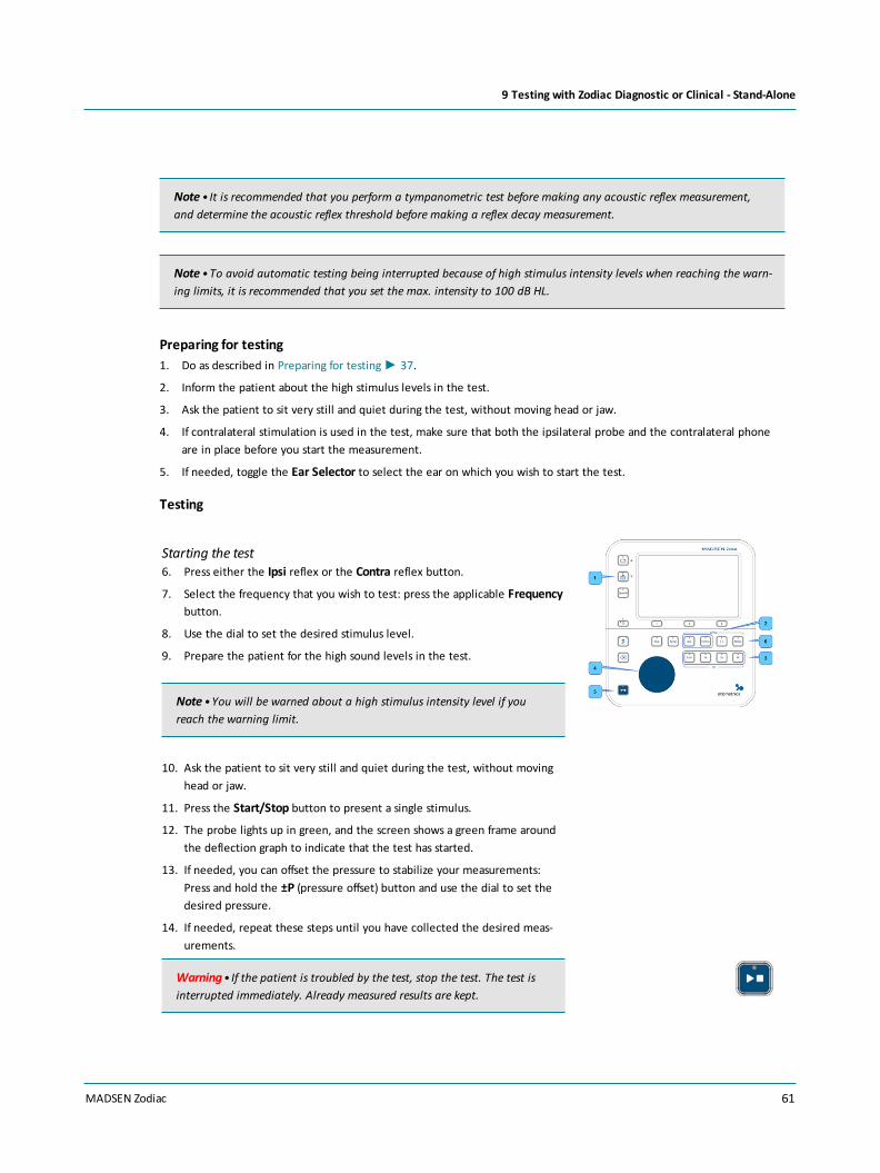
Note • It is recommended that you perform a tympanometric test before making any acoustic reflex measurement,and determine the acoustic reflex threshold before making a reflex decay measurement.
Note •To avoid automatic testing being interrupted because of high stimulus intensity levels when reaching the warn-ing limits, it is recommended that you set the max. intensity to 100 dB HL.
Preparing for testing1. Do as described in Preparing for testing► 37.
2. Inform the patient about the high stimulus levels in the test.
3. Ask the patient to sit very still and quiet during the test, without moving head or jaw.
4. If contralateral stimulation is used in the test, make sure that both the ipsilateral probe and the contralateral phoneare in place before you start the measurement.
5. If needed, toggle the Ear Selector to select the ear on which you wish to start the test.
Testing
Starting the test6. Press either the Ipsi reflex or the Contra reflex button.
7. Select the frequency that you wish to test: press the applicable Frequencybutton.
8. Use the dial to set the desired stimulus level.
9. Prepare the patient for the high sound levels in the test.
Note •You will be warned about a high stimulus intensity level if youreach the warning limit.
10. Ask the patient to sit very still and quiet during the test, without movinghead or jaw.
11. Press the Start/Stop button to present a single stimulus.
12. The probe lights up in green, and the screen shows a green frame aroundthe deflection graph to indicate that the test has started.
13. If needed, you can offset the pressure to stabilize your measurements:Press and hold the ±P (pressure offset) button and use the dial to set thedesired pressure.
14. If needed, repeat these steps until you have collected the desired meas-urements.
Warning• If the patient is troubled by the test, stop the test. The test isinterrupted immediately. Already measured results are kept.
MADSEN Zodiac 61
9 Testing with Zodiac Diagnostic or Clinical - Stand-Alone

Stopping the test1. If the patient is troubled by the test, press the Start/Stop button on the
device or the Start/Stop button on the probe control pad on the shoulderstrap. The test is interrupted and the pump pressure is relieved imme-diately.
Already measured results are kept when a measurement is stopped.
When you have finished testing one ear, switch ears, if needed.
Viewing and managing test results2. To view tympanometry results, see The Reflex Threshold screen► 62.
3. When you have finished testing, see Managing test results in MADSEN Zodiac► 113.
9.6.1 The Reflex Threshold screen
A. On-line valuesB. Reflex Threshold deflection curvesC. Online admittance and pressure indic-
atorsD. Reflex Threshold results tableE. On-screen selections
On-line values
The on-line values show the current settings and status.
• Probe tone in Hz
• Stimulus side (Ipsi is the probe ear, and Contra is the opposite ear)
• Stimulus frequency
• Stimulus level
• Current pressure and admittance scales
62 MADSEN Zodiac
9 Testing with Zodiac Diagnostic or Clinical - Stand-Alone

Reflex Threshold deflection curves
The graph area shows the reflex deflection curves, the associated level and numerical deflection values.
• Reflex deflection curves
The detected threshold is framed in the color of the test ear.
• The dashed horizontal line in each reflex graph indicates the predefined reflex criterion.It is offset from the baseline marker on the vertical axis.
Live baseline graph
The live baseline graph is an online admittance indicator which automatically monitors the admittance of the ear whenthe probe is inserted.
Before you start a measurement, make sure that this baseline is as stable as possible. Fluctuations in the baseline willhave a destructive influence on the reflex measurements
To achieve a stable baseline, there are a number of factors influencing the stability of the baseline:
Patient behavior• The patient is completely still so that noise from the probe cables is minimized.
• The patient must not speak or move the jaws.
• The patient must breathe calmly.
Physiological conditions• Variations that are in synchrony with the patient's pulse:
In some patients, superficial blood vessels may influence the measurement. Try to place the probe at a differentdepth in the ear canal. If the patient in general is troubled by a pulsatile tinnitus, this may indicate that further con-sultation should be done to rule out a vascular middle-ear pathology.
• Variations that are in synchrony with the patient's breathing:This is a sign of Eustachian tube dysfunction and may .prevent further reflex testing.
• Variations due to a very steep tympanogram (for example seen in excessively flaccid tympanic membranes):This problem can usually be remedied by slightly offsetting the air pressure from the tympanometric peak pressure(TPP). In case of a negative TPP, it is recommended that the pressure is offset further in the negative direction. Incase of a positive TPP, it is recommended that the pressure is offset further in the positive direction.
An offset of approximately 20 daPa is usually sufficient to stabilize the baseline. Note that excessive offsets willdecrease the threshold sensitivity by several dB.
Use the pressure offset button ±P to select a pressure offset to stabilize the eardrum. Keep the button depressedand use the dial to select the desired pressure.
MADSEN Zodiac 63
9 Testing with Zodiac Diagnostic or Clinical - Stand-Alone

Reflex Threshold results table
Use the buttons in the Reflex section on the front panel to navigate between the measurements. Your selection is high-lighted in the Reflex results table.
The results table shows the results related to the currently selected curve:
• Stimulus side
• Stimulus frequency
• Threshold levels
On-screen selections
Curve selection Use the soft-buttons Previous Curve or Next Curve to highlight a desired deflec-tion curve.
Set frequency, ipsi and contra Use the settings buttons to select and navigate in order to view curve results.
Set threshold Use the soft-buttons Previous Curve or Next Curve to highlight a desired deflec-tion curve you wish to select as threshold. Press Set Threshold to select.
9.7 Reflex Decay testing
This test is supported by MADSEN Zodiac Diagnostic and MADSEN Zodiac Clinical.
You can record a reflex decay measurement either as a separate measurement or as part of a diagnostic sequence. InSequence testing, the test automatically suggests the stimulus level, which is the reflex threshold level +10 dB.
In the following you will find the description for performing reflex decay testing as a single test. This means that thesequence function is not enabled.
Warning•The Reflex Decay test is a supra-threshold test, where the stimulus levels are very high for an extendedperiod of time. Make sure that there are no contraindications for performing the test.
Note •When you select a special test, the Special button will remain lit until you deselect the special test, e.g. bypressing the Tymp button, or by pressing the Special button a second time.
Note • It is recommended that you perform a tympanometric test before making any acoustic reflex measurement,and determine the acoustic reflex threshold before making a reflex decay measurement.
Note • If Reflex Decay is performed as part of a sequence, the following applies: The decay test stimulus level pre-sup-poses that there is a reflex threshold available for the ear, stimulus type and stimulus ear (ipsi- or contralateral) that is
64 MADSEN Zodiac
9 Testing with Zodiac Diagnostic or Clinical - Stand-Alone

chosen for reflex decay testing. The decay test stimulus level will then automatically be set to the threshold level+10 dB. If the reflex has not been determined, the decay measurement will be skipped.
Note •There may be a warning that the stimulus level is in the extended intensity range. Reflex decay may not be pos-sible due to highly elevated threshold levels.
Note •To avoid automatic testing being interrupted because of high stimulus intensity levels when reaching the warn-ing limits, it is recommended that you set the max. intensity to 100 dB HL.
Before testing1. Do as described in Preparing for testing► 37.
2. Inform the patient about the high stimulus levels in the test.
3. Ask the patient to sit very still and quiet during the test, without moving head or jaw.
4. If contralateral stimulation is used in the test, make sure that both the ipsilateral probe and the contralateral phoneare in place before you start the measurement.
5. If needed, toggle the Ear Selector to select the ear on which you wish to start the test.
Testing
Warning• If the patient is troubled by the test, stop the test. The test is interrupted immediately. Already measuredresults are kept.
Starting the test1. Press the Special button.
2. Select Reflex Decay.
3. The Reflex Decay view is shown and the preselected settings for reflexdecay will light up on the buttons, e.g. Contra, 0.5 k Hz.
4. Use the dial to set the stimulus level. The level is shown in the gray on-line values area of the display.
5. Prepare the patient for the high sound levels in the test. A measurementtakes about 10 seconds.
6. Ask the patient to sit very still and quiet during the test, without movinghead or jaw.
7. Press the Start/Stop button to start the test for the preset stimulus.
8. If needed, repeat these steps until you have collected the desired meas-urements.
MADSEN Zodiac 65
9 Testing with Zodiac Diagnostic or Clinical - Stand-Alone
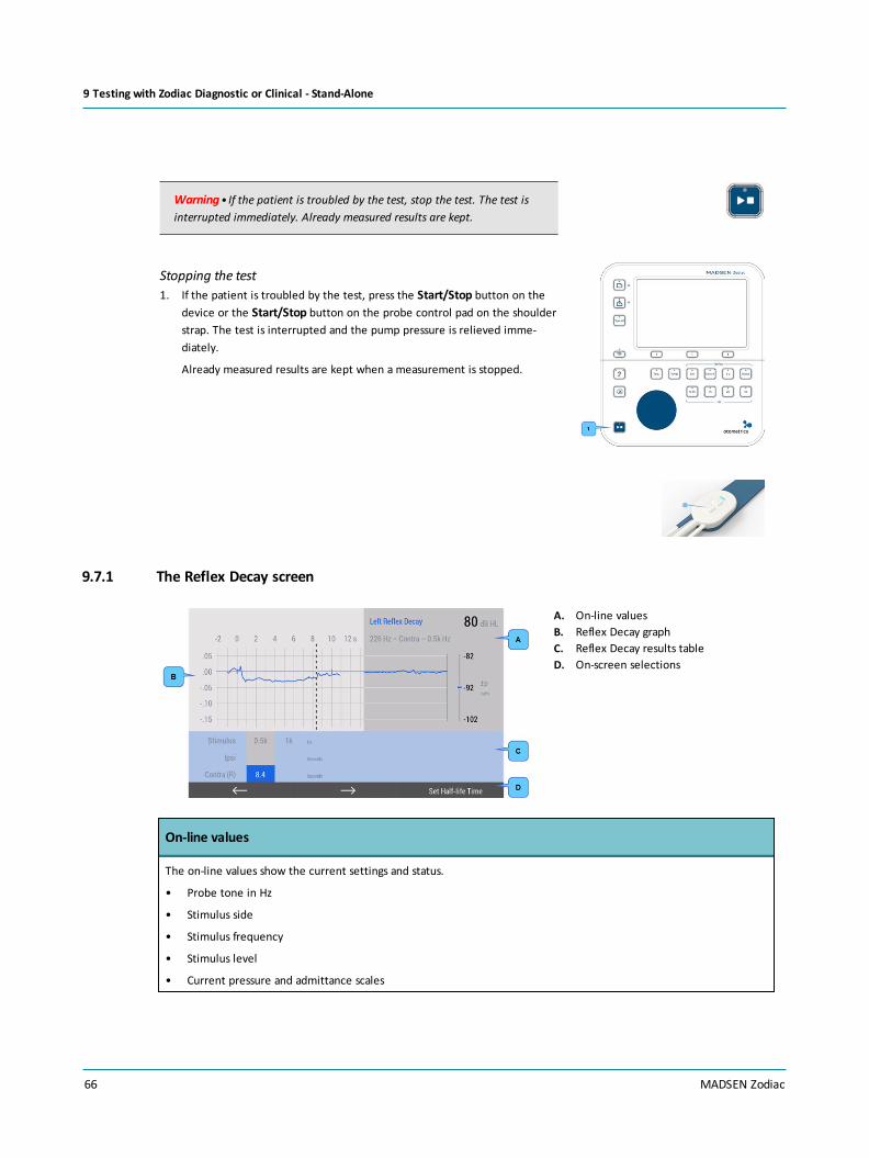
Warning• If the patient is troubled by the test, stop the test. The test isinterrupted immediately. Already measured results are kept.
Stopping the test1. If the patient is troubled by the test, press the Start/Stop button on the
device or the Start/Stop button on the probe control pad on the shoulderstrap. The test is interrupted and the pump pressure is relieved imme-diately.
Already measured results are kept when a measurement is stopped.
9.7.1 The Reflex Decay screen
A. On-line valuesB. Reflex Decay graphC. Reflex Decay results tableD. On-screen selections
On-line values
The on-line values show the current settings and status.
• Probe tone in Hz
• Stimulus side
• Stimulus frequency
• Stimulus level
• Current pressure and admittance scales
66 MADSEN Zodiac
9 Testing with Zodiac Diagnostic or Clinical - Stand-Alone

Reflex Decay graph
The reflex decay graph shows the reflex decay curve and the half-life time for the selected stimulus.
• Time line in seconds
• Stimulus on/stimulus off markers
• Deflection curve for the selected stimulus
• Half-life marker
Reflex Decay results
Use the buttons in the Reflex section on the front panel to navigate between the measurements. Your selection is high-lighted in the Reflex results table.
The results table shows the results related to the currently selected curve:
• Stimulus side
• Stimulus frequency
• Half-life time
If the system cannot automatically analyze a reflex measurement, aNot Tested indication is shown.
On-screen selections
Adjust Marker Press this soft-button so that you can adjust the half-life time marker by using thedial.
Hide Marker/Show Marker If, for example, the result is ambiguous, you can hide a half-life time marker.Alternatively, you can show the marker.
Done When you have adjusted the marker, press the Done soft-button.
The results table is updated with the selected value.
9.8 Manual Tympanometry
In Manual Tympanometry you can control the pump pressure manually.
The default setup available in the tympanometry test is designed for any of the tympanometry tests you canperform. Adjust the settings to suit your purposes.
Preparing for testing1. Do as described in Preparing for testing► 37.
2. Ask the patient to sit very still and quiet during the test, without moving head or jaw.
3. If needed, toggle the Ear Selector to select the ear on which you wish to start the test.
The probe lights up in the ear color to indicate that it is activated.
4. Press the Special button and select Manual Tymp.
MADSEN Zodiac 67
9 Testing with Zodiac Diagnostic or Clinical - Stand-Alone
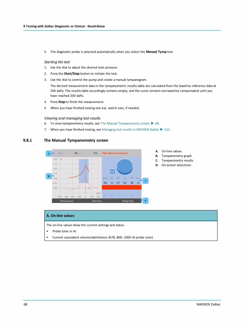
5. The diagnostic probe is selected automatically when you select the Manual Tymp test.
Starting the test1. Use the dial to adjust the desired start pressure.
2. Press the Start/Stop button to initiate the test.
3. Use the dial to control the pump and create a manual tympanogram.
The derived measurement data in the tympanometric results table are calculated from the baseline reference data at200 daPa. The results table accordingly remains empty, and the curve remains non-baseline compensated until youhave reached 200 daPa.
4. Press Stop to finish the measurement.
5. When you have finished testing one ear, switch ears, if needed.
Viewing and managing test results6. To view tympanometry results, see The Manual Tympanometry screen► 68.
7. When you have finished testing, see Managing test results in MADSEN Zodiac► 113.
9.8.1 The Manual Tympanometry screen
A. On-line valuesB. Tympanometry graphC. Tympanometry resultsD. On-screen selections
A. On-line values
The on-line values show the current settings and status.
• Probe tone in Hz
• Current equivalent volume/admittance (678, 800, 1000 Hz probe tone)
68 MADSEN Zodiac
9 Testing with Zodiac Diagnostic or Clinical - Stand-Alone

B. Tympanometry graph
The graph area shows the tympanometric curves and can rescale automatically to fit the curves.
• Tympanometric curves
• Pressure and admittance scales
• Ear canal volume bar. The ear canal volume is shown to the right of the graph.
• Norm area
C. Tympanometry results
The results table shows the results related to the currently selected curve:
• Probe (the probe tone in Hz)
• TPP offset (Tympanometric Peak Pressure)
• ECV (Equivalent Ear Canal Volume)
• SA (Static Peak Admittance), or SC (Static Peak Compliance) when volume equivalent units are used
• TW/Ratio (Tympanometric Width/Tympanometric Ratio). Describes the steepness of the curve.
• Type (Jerger types A, As, Ad, B, C, D and E denote the shape of the 226 Hz curve). You can set the type to bedetermined automatically, and you can subsequently change it manually, if necessary.
D. On-screen selections
Curve selection Press the Previous Curve or Next Curve softbutton to select the desired curve inthe Reflex Screening and Tympanometry result tables.
Changing tympanogram curve type Press the Change Type button until the desired tympanogram type is shown.
Deleting a curve Select the curve you wish to delete, and press the Delete button.
To replace a single measurement, delete a curve and adjust the measurementselections to redo the single measurement.
9.9 Admittance (Y) Recorder
Admittance (Y) Recorder is a functionality where you can record the admittance either without stimulus or with anyexternal stimulus. The functionality can be useful both for investigative purposes and troubleshooting in conjunction withunstable acoustic reflex traces.
Admittance (Y) Recorder is useful for several purposes such as:
• Reflex testing of the stapedius muscle
– external electrical stimulation with cochlear implants
– tactile stimulation
• Patulous Eustachian tube testing
MADSEN Zodiac 69
9 Testing with Zodiac Diagnostic or Clinical - Stand-Alone

Admittance variations in synchrony with the patient's breathing cycle resulting from insufficient closing of the Eus-tachian tube
• Vascular artefacts
Admittance variations in synchrony with the patient's pulse. This phenomenon can be observed in some casesinvolving superficial blood vessels that influence the probe or the tympanic membrane. The condition is sometimesobserved as a pulsatile objective tinnitus. It may indicate the presence of a Glomus tumor.
Physiological conditions• Variations that are in synchrony with the patient's pulse:
In some patients, superficial blood vessels may influence the measurement. Try to place the probe at a different depthin the ear canal. If the patient in general is troubled by a pulsatile tinnitus, this may indicate that further consultationshould be done to rule out a vascular middle-ear pathology.
• Variations that are in synchrony with the patient's breathing:This is a sign of Eustachian tube dysfunction and may .prevent further reflex testing.
• Variations due to a very steep tympanogram (for example seen in excessively flaccid tympanic membranes):This problem can usually be remedied by slightly offsetting the air pressure from the tympanometric peak pressure(TPP). In case of a negative TPP, it is recommended that the pressure is offset further in the negative direction. In caseof a positive TPP, it is recommended that the pressure is offset further in the positive direction.
An offset of approximately 20 daPa is usually sufficient to stabilize the baseline. Note that excessive offsets willdecrease the threshold sensitivity by several dB.
Use the pressure offset button ±P to select a pressure offset to stabilize the eardrum. Keep the button depressed anduse the dial to select the desired pressure.
Before testing1. Do as described in Preparing for testing► 37.
2. Inform the patient about the high stimulus levels in the test.
3. Ask the patient to sit very still and quiet during the test, without moving head or jaw.
4. If contralateral stimulation is used in the test, make sure that both the ipsilateral probe and the contralateral phoneare in place before you start the measurement.
5. If needed, toggle the Ear Selector to select the ear on which you wish to start the test.
Testing
Warning• If the patient is troubled by the test, stop the test. The test is interrupted immediately. Already measuredresults are kept.
70 MADSEN Zodiac
9 Testing with Zodiac Diagnostic or Clinical - Stand-Alone

Starting the test1. Press the Special button.
2. Select Y Recorder.
3. The Y Recorder view is shown.
4. Place the probe in the patient’s ear.
5. Ask the patient to sit very still and quiet during the test, without movinghead or jaw.
6. Click the Start/Stop button to start recording.
7. If needed, press the ± P pressure offset button and simultaneously use thedial to adjust the pressure.
Warning• If the patient is troubled by the test, stop the test. The test isinterrupted immediately. Already measured results are kept.
8. If needed, press the Pause softbutton to pause the test. This can be usefulfor instance when recording acoustic reflexes using external stimuli (forexample electric stimulus during cochlear implant surgery).
9. The measurement stops automatically after 30 seconds, but you can stop itmanually before.
10. You can record one measurement per ear.
9.9.1 The Admittance (Y) Recorder screen
A. Admittance Recorder graph
Admittance Recorder graph
• Time line in seconds
• The recorded admittance graph shown in the left graph area
• The live baseline graph shown in the right graph area
MADSEN Zodiac 71
9 Testing with Zodiac Diagnostic or Clinical - Stand-Alone

9.10 ETF-P
ETF-P can be performed on ears with eardrum perforations prior to reconstructive surgery to evaluate whether the middleear could be ventilated through the Eustachian tube following tympanoplasty. Air must be able to pass through the Eus-tachian tube in order to equalize the middle ear pressure following reconstructive surgery.
For testing the Eustachian tube function in ears with perforated eardrums (ETF-P), a method different from immittancemeasurements is used. In ETF-P, the ear air pressure is monitored continuously to detect any airflow through the Eus-tachian tube.
An initial positive or negative air pressure is applied to the ear through the probe (positive pressure is recommended). Dueto the eardrum perforation, the pressure will be applied to both the ear canal and middle ear cavities. The patient is theninstructed to swallow some water, which typically causes a functioning Eustachian tube to open. Any pressure equalizationthrough the tube will show as a sudden pressure drop toward, but not necessarily reaching, atmospheric pressure (0 daPa).This is repeated until the pressure is equalized or until the test is stopped. The pressures at which the tube opens andcloses are reported as test results.
Typically, an initial build-up of positive pressure will cause the Eustachian tube to open spontaneously. In order to avoidpremature spontaneous pressure equalization related to positive pressure build-up, the pump speed should be kept at amaximum of 50 daPa/s.
Procedure
1. Record a tympanogram to confirm the perforation. The resulting tym-panogram curve will be flat, and the ear canal volume will be abnormallyhigh because it includes the volume of the entire middle ear.
See Tympanometry testing► 90.
2. Press the Special button.
3. Scroll to select the ETF-P test.
4. Press the OK soft-button.
5. If needed, use the dial to adjust the initial pressure.
6. Press the Start/Stop button on the device or the Start/Stop button on theprobe control pad on the shoulder strap.
Positive pressure automatically builds up until the first opening of the Eus-tachian tube or max. pressure is reached.
The time scale is 30 seconds.
7. Press the Stop Pump softbutton to manually stop the pump when the airpressure stabilizes (if the pressure stops increasing before the target pressurehas been reached).
8. Instruct the patient to perform the preferred equalizing method, for examplehaving a sip of water.
This ETF-P test result shows an example where the pressure changes throughoutthe measurement as the Eustachian tube briefly opens and closes. The patternmay differ depending on the patient.
72 MADSEN Zodiac
9 Testing with Zodiac Diagnostic or Clinical - Stand-Alone
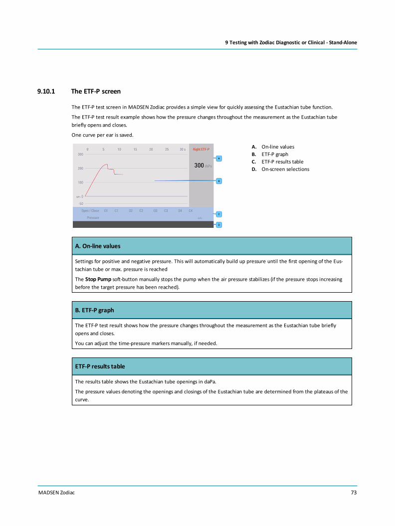
9.10.1 The ETF-P screen
The ETF-P test screen in MADSEN Zodiac provides a simple view for quickly assessing the Eustachian tube function.
The ETF-P test result example shows how the pressure changes throughout the measurement as the Eustachian tubebriefly opens and closes.
One curve per ear is saved.
A. On-line valuesB. ETF-P graphC. ETF-P results tableD. On-screen selections
A. On-line values
Settings for positive and negative pressure. This will automatically build up pressure until the first opening of the Eus-tachian tube or max. pressure is reached
The Stop Pump soft-button manually stops the pump when the air pressure stabilizes (if the pressure stops increasingbefore the target pressure has been reached).
B. ETF-P graph
The ETF-P test result shows how the pressure changes throughout the measurement as the Eustachian tube brieflyopens and closes.
You can adjust the time-pressure markers manually, if needed.
ETF-P results table
The results table shows the Eustachian tube openings in daPa.
The pressure values denoting the openings and closings of the Eustachian tube are determined from the plateaus of thecurve.
MADSEN Zodiac 73
9 Testing with Zodiac Diagnostic or Clinical - Stand-Alone

E. On-screen selections
Adjust Markers Press this soft-button so that you can adjust the time-pressure markers by usingthe dial.
Next Marker Press this soft-button to cycle through the markers that can be shown per ear(maximum eight markers).
Hide Marker/Show Marker You can hide a half-life time marker. Alternatively, you can show the marker.
Done When you have adjusted the marker, press the Done soft-button.
The results table is updated with the selected value.
74 MADSEN Zodiac
9 Testing with Zodiac Diagnostic or Clinical - Stand-Alone

10 The Otosuite Immittance module
10.1 Otosuite toolbar icons and control panels
General toolbar iconsSee the Otosuite User Guide for a detailed description.
Test screen examples
Tympanometry and Reflex Screening - Quick Check version
A. Starting and ending a sessionB. Measurement selections and carrying
out testsC. Viewing test dataD. Editing resultsE. Selecting other test types
Tympanometry and Reflex Screening - Diagnostic and Clinical version
A. Starting and ending a sessionB. Measurement selections and carrying
out testsC. Viewing test dataD. Editing resultsE. Selecting other test types
MADSEN Zodiac 75
10 The Otosuite Immittance module

Starting and ending a session
Toolbar icons
The icons available in the toolbar depend on the test function that you have selected.
Edit client details
• Click to create a new session.
Print default report
• Click to print the default test report for the current patient.
Probe Check
• If needed, click to perform a probe check.
Measurement selections
Activate and deactivate test functions
Activate test functions
• Click to activate the test or test setting you wish to use. The button turns yellow to indicate that thefunction is active.
Deactivate test functions
• Click to deactivate the test or test setting you do not wish to use. The button turns gray to indicate thatthe function is deactivated.
Tymp. and Reflex Scr.
Tymp (tympanometry)
• Click to select the Tymp test.
Reflex Screening
• Click to add Reflex Screening to the Tymp test.
Reflex Screening frequencies (Hz)
• Click to select the desired pure tone frequencies for the reflex screening measurement:
– 0.5 kHz
– 1 kHz
– 2 kHz
– 4 kHz
76 MADSEN Zodiac
10 The Otosuite Immittance module

Noise - Reflex Screening noise stimulus
• Click to select Broadband noise as a reflex stimulus.
Reflex Threshold, Reflex Decay, Reflex Latency
Ipsi (ipsilateral)
• Click to select the stimulus presentation side for reflex testing of the probe ear.
Contra (contralateral)
• Click to select the stimulus presentation in the non-probe ear.
± P (Offset target pressure from TPP)
• Click the desired arrow to select a pressure offset to stabilize the tympanic membrane. This mayfacilitate reflex recordings from ears that have steeply sloped tympanograms.
Set stimulus type
• Click the desired arrow to set the stimulus type.
Set stimulus level
• Click the desired arrow to increase or decrease the stimulus level.
Manual
• Click to select a manual reflex threshold search. Each stimulus will be presented individually.
Auto
• Click to select an automatic reflex threshold search. The stimuli will be presented in a sequence.
Probe Tone
• Click to select the desired probe tone in Hz:
– 226
– 768 (Clinical only)
– 800 (Clinical only)
– 1000
Admittance Recording
Start Admittance Recording
• Click to start recording admittance changes.
MADSEN Zodiac 77
10 The Otosuite Immittance module

ETF-P
Set positive pressure (daPa)
• Click to set the positive target pressure.
Set negative pressure (daPa)
• Click to set the negative target pressure.
Sequence testing
Automatic sequence testing
This function allows you to combine multiple diagnostic measurements and run them in an automatedsequence.
When you press Start, all functions that have been selected for the sequence are performed: e.g. Tym-panometry + Ipsi and Contra Reflex Thresholds at several frequencies.
You can adjust any settings related to the tests included in the sequence.
You can choose if you want to start sequences or individual tests on the shoulder pad.
Screening sequence:Tympanometry + Reflex Screening.
Diagnostic sequence:Tympanometry + Reflex Threshold (+ Reflex Decay, if selected from the Sequence Settings dialog).
Setting up a sequence
1. In the Sequence area of the control panel click theSequence Options button to select tests and specific set-tings.
2. Click the checkboxes next to the tests you wish toinclude in the sequence.
3. If needed, modify the reflex settings you wish to includein the automatic test sequences.
Note •You can enable an option to start sequences dir-ectly from the shoulder pad Start button.
78 MADSEN Zodiac
10 The Otosuite Immittance module

Running tests
Ear
This button is located both on the Control Panel and on the probes.
Click or press this button to toggle the ear selection associated with the current measurement. The buttonshows the color of the selected ear.
Start/Stop
This button is placed both on the Control Panel and on the diagnostic probe shoulder strap.
• Click or press this button to perform a tympanometric measurement and to start reflex tests (and, addi-tionally to present stimuli for manual reflex testing).
• During a test, click or press this button to stop the test.
Present stimulus manually
• Click to make a manual reflex threshold.
Start recording (Admittance Recording)
• Click to start recording admittance variations.
Viewing test data
The tympanogram
Toggle to view the tympanogram in binaural or monaural mode.
Retrieve data from device.
Toggle to see the admittance components conductance and susceptance, or admittance data.
Admittance is selected
Susceptance/Conductance is selected
Susceptance is selected
Conductance is selected
MADSEN Zodiac 79
10 The Otosuite Immittance module

The tympanogram
Auto Scale (tympanogram)
Click to select/deselect autoscaling of a tympanogram in order to display the entire curve. When you changethe ear or the patient, the scale will revert to the default scale.
Selecting other test types
Test type tabs Click to select the desired test type:
• Tymp. and Reflex Scr.
• Reflex Threshold
• Admittance Recording
• ETF-P
• Manual Tymp
10.2 Shortcut keys
General
Function Shortcut
Sequence panel/Manual panel S (toggle)
Probe tone P (cycle)
User test F8
Tympanometry and Reflex Screening
Function Shortcut
Start measurement F5/Spacebar
Stop measurement F5/Esc
Select Tympanometry T (toggle)
Select Reflex Screening R
500 Hz 5
1000 Hz 1
2000 Hz 2
4000 Hz 4
Noise N
80 MADSEN Zodiac
10 The Otosuite Immittance module

Reflex Threshold
Function Shortcut
Start measurement F5/Spacebar
Stop measurement F5/Esc
Level up Arrow up
Level down Arrow down
Frequency up Arrow right
Frequency down Arrow left
Ipsilateral I
Contralateral C
Adjust pressure - positive Shift + Arrow up
Adjust pressure - negative Shift + Arrow down
500 Hz 5
1000 Hz 1
2000 Hz 2
4000 Hz 4
Noise N
Reflex Decay
Function Shortcut
Start measurement F5/Spacebar
Stop measurement F5/Esc
Level up Arrow up
Level down Arrow down
Frequency up Arrow right
Frequency down Arrow left
Ipsilateral I
Contralateral C
Adjust pressure - positive Shift + Arrow up
Adjust pressure - negative Shift + Arrow down
500 Hz 5
1000 Hz 1
MADSEN Zodiac 81
10 The Otosuite Immittance module

ETF-P
Function Shortcut
Start measurement F5/Spacebar
Stop measurement F5/Esc
Pressure up Arrow up
Pressure down Arrow down
Admittance (Y) monitoring
Function Shortcut
Start measurement F5/Spacebar
Stop measurement F5/Esc
ETF-I
Function Shortcut
Start measurement F5/Spacebar
Stop measurement F5/Esc
Continue Enter
10.3 Leakage and other probe problems
Testing may be complicated by a number of factors which can result in leakage or probe problems.
Leakage - possible causes:• The eartip does not fit well
• The eartip is not inserted properly in the ear canal
• The probe tip opening is blocked by the wall of the ear canal
• The eartip may be old or hardened
• the threaded ring holding the probe tip has not been tightened properly
• The pneumatic probe plug has not been inserted properly in Zodiac
• the probe tip has not been tightened properly
Probe problems can be caused by:• an occluded probe
• a blocked wax filter
Leakage and probe occlusion is shown on the screen during testing.
82 MADSEN Zodiac
10 The Otosuite Immittance module

Probe status
The light indicatorsLight indicators light up in color in the probe to indicate different states. The control pad on the shoulder strap shows theselected ear color at all times, if you are using the diagnostic probe.
Probe color Status
Red • The right test ear has been selected
• The device is in idle mode
Blue • The left test ear has been selected
• The device is in idle mode
Green • The test is running
Yellow • Leak
Otosuite indications
Color Status
Green • During measurements, Otosuite shows a green background to the onlinevalues.
Probe leakage
Stand-aloneIf there is a probe leak during testing, this will be shown on the MADSEN Zodiac and Otosuite screens.
PC-basedIf there is a probe leak during testing, this will be shown on the Otosuite screen.
If you are using the Quick Check probe, the leakage indication will remain until you remove the probefrom the ear and try again.
Probe blocked
Stand-aloneIf the probe is blocked during testing, this will be shown on the MADSEN Zodiac and Otosuite screens.
PC-basedIf the probe is blocked during testing, this will be shown on the Otosuite screen.
If you are using the Quick Check probe, the blocked probe indication will remain until you remove theprobe from the ear and try again.
MADSEN Zodiac 83
10 The Otosuite Immittance module

11 Testing with Zodiac Quick Check - PC-basedWhen you use a PC-based Zodiac for testing, the Otosuite Immittance module provides you with the various test screensneeded. The tests and features you can use depend on the configuration of the test device connected to Otosuite.
Using OtosuiteWe recommend that you make yourself familiar with the general Otosuite functions described in the Otosuite Platformdocumentation.
The general functions for navigating in the main window are described in the Otosuite Platform documentation.
Immittance tests and screen descriptionsYou will find descriptions of the test and screen, and how to use and view them in:
• Quick Check testing► 89
11.1 Starting a measurement
To prepare for the test before you start testing, see Preparing for testing► 37.
1. Look into the ear canal. It is strongly recommended that you perform an otoscopy to assess the status of the outer earbefore you insert the probe.
2. If the ear canal is blocked, this may affect the result of the test. Clean the ear canal if needed.
Caution•The probe can be damaged if fluids enter the probe.
Fit the probe in the ear
Warning•Always fit the probe with a new eartip when you place the probe in the ear canal of a new patient.
Warning•The eartip can be used for both ears. If you suspect infection in one ear, use a clean eartip and probe tipbefore you continue testing on the other ear.
Caution•Avoid excessive force when you place the ear tip against the ear canal opening of the patient as this maycause unnecessary discomfort, particularly if the eartip is small enough to enter the ear canal.
1. With a hand-held probe you can use a slightly over-sized eartip in order to achieve a seal when usedwith a wider range of ear canal sizes.
The oversized eartip is not intended to enter theear canal.
2. Fit the eartip on the probe.
84 MADSEN Zodiac
11 Testing with Zodiac Quick Check - PC-based

The Quick Check probe:3. Press the probe against the patient's ear canal so
that a hermetic seal is achieved. The meas-urement starts automatically.
4. To stabilize the probe and to avoid blocking theprobe against the ear canal of the patient, graspthe pinna and gently pull the pinna back andslightly away from the patient's head.
– For adults: pull the pinna upwards and back.
– For infants and children: pull the pinna down-wards and back.
Quick Check probe placement
5. Make sure that the eartip fits well. This will min-imize the risk of blocking the probe tip against theear canal wall. A flat tympanogram together withan abnormally small ear canal volume (ECV) indic-ates that the probe is blocked.
A measurement will not autostart if the ear canalvolume reading is less than 0.1.
6. Any leakage will interrupt the test. The probe willindicate if there is a leak.
Probe status and leakage
The light indicatorsLight indicators light up in color in the probe to indicate different states. The control pad on the shoulder strap shows theselected ear color at all times, if you are using the diagnostic probe.
Probe color Status
Red • The right test ear has been selected
• The device is in idle mode
Blue • The left test ear has been selected
• The device is in idle mode
Green • The test is running
Yellow • Leak
MADSEN Zodiac 85
11 Testing with Zodiac Quick Check - PC-based

Probe leakage
Stand-aloneIf there is a probe leak during testing, this will be shown on the MADSEN Zodiac and Otosuite screens.
PC-basedIf there is a probe leak during testing, this will be shown on the Otosuite screen.
If you are using the Quick Check probe, the leakage indication will remain until you remove the probefrom the ear and try again.
Probe blocked
Stand-aloneIf the probe is blocked during testing, this will be shown on the MADSEN Zodiac and Otosuite screens.
PC-basedIf the probe is blocked during testing, this will be shown on the Otosuite screen.
If you are using the Quick Check probe, the blocked probe indication will remain until you remove theprobe from the ear and try again.
11.2 The Quick Check measurement screen
When the measurement starts, you will see the measurement being performed real-time on the screen.
A. Control panel selectionsB. Tympanometry graphC. Reflex Screening resultsD. Tympanometry results
A. Control panel selections
The control panel shows the selections that are enabled for this test.
You can select or deselect the tympanometry sweep, and select Reflex Screening where you can enable or disable thestimulus types for the test.
86 MADSEN Zodiac
11 Testing with Zodiac Quick Check - PC-based

B. Tympanometry graph
The graph area shows the tympanometric curves and can rescale automatically to fit the curves.
• Tympanometric curves
• Pressure and admittance scales
• Ear canal volume bar
• Norm area
The ear canal volume is shown to the right of the graph.
C. Reflex Screening results
The detected reflex is shown in the results area.
• Stimulus type level
• Deflection curves
If a reflex is not detected, then the curve of the loudest stimulus is displayed together with a No Response indication.
D: Tympanometry results
The results table shows the results related to the currently selected curve:
• Probe (the probe tone in Hz)
• TPP (Tympanometric Peak Pressure)
• ECV (Equivalent Ear Canal Volume
• SA (Static Admittance), or SC (Static Compliance) when volume equivalent units are used
• TW/Ratio (Tympanometric Width/Tympanometric Ratio). Describes the steepness of the curve.
• Type (Jerger types A, As, Ad, B, C, D and E denote the shape of the 226 Hz curve). You can set the type to bedetermined automatically, and you can subsequently change it manually, if necessary.
MADSEN Zodiac 87
11 Testing with Zodiac Quick Check - PC-based

12 Testing with Zodiac Diagnostic or Clinical - PC-basedWhen you use a PC-based Zodiac for testing, the Otosuite Immittance module provides you with the various test screensneeded. The tests and features you can use depend on the configuration of the test device connected to Otosuite.
Using OtosuiteWe recommend that you make yourself familiar with the general Otosuite functions described in the Otosuite Platformdocumentation.
The general functions for navigating in the main window are described in the Otosuite Platform documentation.
Immittance tests and screen descriptionsYou will find descriptions of the tests and screens, and how to use and view them in:
• Quick Check testing► 89
• Tympanometry testing► 90
• Reflex Threshold testing► 95
• Reflex Decay testing► 100
• Admittance (Y) Recorder► 105
• ETF-P► 108
• Manual Tympanometry► 103
12.1 Sequence testing
Depending on the configuration of your Zodiac, you can perform tympanometry and reflex measurements in predefined,automated sequences.
12.1.1 Setting up a sequence
1. In the Sequence area of the control panel click the Sequence Optionsbutton to select tests and specific settings.
2. Click the checkboxes next to the tests you wish to include in thesequence.
3. If needed, modify the reflex settings you wish to include in the auto-matic test sequences.
Note •You can enable an option to start sequences directly from theshoulder pad Start button.
88 MADSEN Zodiac
12 Testing with Zodiac Diagnostic or Clinical - PC-based

12.1.2 Running a test sequence
Starting a sequence
1. Select the desired sequence from the Immittance module control panel.
2. Click Start to start the selected sequence.
Warning• If the patient is troubled by the test, stop the test. The test is interrupted immediately.Already measured results are kept.
In reflex testing the data collection will be paused before each stimulus above 100 dB HL, and you willbe prompted to continue.
Stopping a sequenceIf a leak is detected or the probe is removed from the patient's ear, the sequence stops automatically.
1. Click Stop to stop the sequence manually.
2. If needed, perform supplementary measurements. You can supplement an interrupted sequence bydeselecting the successful part and then restart the sequence testing.
12.2 Quick Check testing
You can perform Tympanometry and Reflex Screening as a Quick Check test from the Tymp + Reflex Screening screen.
Note •The safety intensity level cannot be exceeded in screening mode.
Preparing for testing1. Do as described in Preparing for testing► 37.
2. Launch the Immittance module with the Tymp + Reflex Screening screen selected.
3. Ask the patient to sit very still and quiet during the test, without moving head or jaw.
4. If needed, toggle the Ear Selector to select the ear on which you wish to start the test.
5. Load a test setting configured for Quick Check testing of patients in the relevant age group.
Procedure1. To prepare the probe for Quick Check testing, press the Start button on the probe or shoulder pad before you insert
it into the ear canal of the patient.
MADSEN Zodiac 89
12 Testing with Zodiac Diagnostic or Clinical - PC-based

The Quick Check probe:2. Press the probe against the patient's ear canal so
that a hermetic seal is achieved. The meas-urement starts automatically.
3. To stabilize the probe and to avoid blocking theprobe against the ear canal of the patient, graspthe pinna and gently pull the pinna back andslightly away from the patient's head.
– For adults: pull the pinna upwards and back.
– For infants and children: pull the pinna down-wards and back.
Quick Check probe placement
The diagnostic probe:4. Place the shoulder strap on the shoulder of the
patient.
5. To stabilize the probe and to avoid blocking theprobe against the ear canal of the patient, graspthe pinna and gently pull the pinna back andslightly away from the patient's head.
– For adults: pull the pinna upwards and back.
– For infants and children: pull the pinna down-wards and back.
6. Insert the probe in the patient's ear canal whiletwisting the probe gently. When the probe is inplace, remove your hands carefully.
Diagnostic probe placement
7. Make sure that the eartip fits well. This will min-imize the risk of blocking the probe tip against theear canal wall. A flat tympanogram together withan abnormally small ear canal volume (ECV) indic-ates that the probe is blocked.
A measurement will not autostart if the ear canalvolume reading is less than 0.1.
8. Any leakage will interrupt the test. The probe willindicate if there is a leak.
12.3 Tympanometry testing
You can record a tympanogram either as a separate measurement or as part of a diagnostic or screening sequence. In asequence, tympanometry is automatically followed by reflex testing.
In the following you will find the description for performing tympanometry as a single test. This means that the sequencefunction is not enabled.
90 MADSEN Zodiac
12 Testing with Zodiac Diagnostic or Clinical - PC-based

The default setup available in the tympanometry test is designed for any of the tympanometry tests you canperform. Adjust the settings to suit your purposes.
Preparing for testing1. Do as described in Preparing for testing► 37.
2. If contralateral stimulation is used in the test, make sure that both the ipsilateral probe and the contralateral phoneare in place before you start the measurement.
3. Ask the patient to sit very still and quiet during the test, without moving head or jaw.
4. If needed, toggle the Ear Selector to select the ear on which you wish to start the test.
Activating the probeIf the probe is not activated (the probe light is not lit), activate the probe:
• The diagnostic probe: Press the Ear button on Zodiac or the Start/Stopbutton on the control pad.
• The Quick Check probe: Press the Ear button on the probe.
The probe lights up in the ear color to indicate that it is activated.
Starting the test1. Click the Tymp. and Reflex Scr. tab on the screen.
1. Click the Tymp button on the control panel.
2. Place the probe in the patient’s ear.
3. Ask the patient to sit very still and quiet during the test, without movinghead or jaw.
4. Click the Start/Stop button to start the test.
Quick Check probe:
– The test starts automatically when seal is achieved in the ear canal.
Diagnostic probe:
– Press the Start/Stop button on the device or the Start/Stop buttonon the probe control pad on the shoulder strap.
With the diagnostic probe you can also use automatic start: Pressthe Start/Stop button before placing the probe in the patient’s ear.
The test progresses as follows:
– The pump increases the pressure to the set value, and the sweep starts.
– The admittance for each pressure point is plotted out on the screen and forms the tympanogram curve.
Stopping the testThe test stops automatically, but can be stopped manually, if needed.
1. Click the Stop button on the Control Panel or the Start/Stop button on the probe.
2. The test is interrupted immediately.
MADSEN Zodiac 91
12 Testing with Zodiac Diagnostic or Clinical - PC-based

Making a new tympanometry sweep1. To make a new sweep, click the Start button.
If you wish to overwrite a tympanogram, in the results table click to highlight the curve you wish to overwrite.
When you have finished testing one ear, switch ears, if needed.
Viewing and managing test results2. To view tympanometry results, see The Tympanometry screen► 92.
3. When you have finished testing, see Managing test results in MADSEN Zodiac► 113.
12.3.1 The Tympanometry screen
When the measurement starts, you will see the measurement being performed real-time on the screen.
A. Control panel selectionsB. Tympanometry graphC. Results table
A. Control panel selections
The measurement type and the probe tone in Hz.
B. Tympanometry graph
The graph area shows the tympanometric curves and can rescale automatically to fit the curves.
• Tympanometric curves
• Pressure and admittance scales
• Ear canal volume bar. The ear canal volume is shown to the right of the graph.
• Norm area
92 MADSEN Zodiac
12 Testing with Zodiac Diagnostic or Clinical - PC-based

C. Results table
The results table shows the results related to the currently selected curve. When you click on a row of results, therelated curve is highlighted in the tympanometry graph area.
To replace a single measurement, delete a curve and adjust the measurement selections to redo the single meas-urement.
• Probe check (the probe tone in Hz)
• TPP (Tympanometric Peak Pressure)
• ECV (Equivalent Ear Canal Volume
• SA (Static Admittance), or SC (Static Compliance) when volume equivalent units are used
• TW/Ratio (Tympanometric Width/Tympanometric Ratio). Describes the steepness of the curve.
• Type (Jerger types A, As, Ad, B, C, D and E denote the shape of the 226 Hz curve). You can set the type to bedetermined automatically, and you can subsequently change it manually, if necessary.
Primary tympanogramsThe most recently recorded tympanogram is by default set as the primary tympanogram. The primary tympanogram isautomatically used to set the appropriate air pressure for reflex measurements and is shown in a small graph in thereflex measurements test tabs.
Editing results
To edit the measurement results inthe results table, right-click on themeasurement row you wish toedit, and select from the menu.
• Move up
• Move down
• Set as Primary
• Change Type
• Swap Ear...
• Delete Curve
• Delete all curves for this ear
12.4 ETF-I (Eustachian Tube Function - Intact) testing
Note •This test is available only if MADSEN Zodiac supports diagnostic testing.
MADSEN Zodiac 93
12 Testing with Zodiac Diagnostic or Clinical - PC-based

Procedure
Three result rows in the Tympanometry results table willbe used for this test.
If you wish to print them, make sure that all three areselected in the Tympanometry results table.
1. Select the Tymp. and Reflex Scr. test screen.
2. Record a tympanogram.
3. Instruct the patient to perform a pressure equalizationmaneuver.
4. Record a second tympanogram.
5. Compare the tympanograms from step 1 and 3 in themultilayered tympanogram.
6. It may be useful to repeat the procedure using dif-ferent techniques and maneuvers in a sequence of test-ing to fully evaluate the functioning of the Eustachiantube.
Note •You can also use Manual Tympanometry for ETF-I. In Manual Tympanometry you can facilitate the equal-ization maneuvers by keeping the pressure between measurements.
12.5 Acoustic reflex testing
MADSEN Zodiac determines acoustic reflexes automatically using different stimulus levels.
Note • It is recommended that you perform a tympanometric test before making any acoustic reflex measurement,and determine the acoustic reflex threshold before making a reflex decay measurement.
Note • If you have performed a tympanometric test, where the tympanogram is very steep (TW is less than 40 daPa), aTPP offset is automatically applied to stabilize the reflex measurement.
High intensity levels
Note •To avoid automatic testing being interrupted because of high stimulus intensity levels when reaching the warn-ing limits, it is recommended that you set the max. intensity to 100 dB HL. You can always supplement automaticreflex measurements with manual testing, if needed.
94 MADSEN Zodiac
12 Testing with Zodiac Diagnostic or Clinical - PC-based

Warning•The sound pressure level in the ear canal increases when you test patients with small ear canals. Alwayscomply with local practice and recommendations for presenting loud stimuli.
Whenever an intensity level exceeds the warning level (> 100 dB HL), a warning message will be shown, and you will beprompted to decide whether to continue or to move on to the next stimulus type.
12.6 Reflex Threshold testing
Note • It is recommended that you perform a tympanometric test before making any acoustic reflex measurement,and determine the acoustic reflex threshold before making a reflex decay measurement.
This test is supported by MADSEN Zodiac Diagnostic and MADSEN Zodiac Clinical.
You can record a reflex threshold either as a separate measurement or as part of a diagnostic sequence. In Sequence test-ing, the test automatically suggests the threshold level. Always carefully review this result and adjust it if necessary.
Manual Reflex Threshold testing: see Manual Reflex Threshold testing► 95.
Automated Reflex Threshold testing: see Automated Reflex Threshold testing► 97.
Preparing for testing1. Do as described in Preparing for testing► 37.
2. Inform the patient about the high stimulus levels in the test.
3. Ask the patient to sit very still and quiet during the test, without moving head or jaw.
4. If contralateral stimulation is used in the test, make sure that both the ipsilateral probe and the contralateral phoneare in place before you start the measurement.
5. If needed, toggle the Ear Selector to select the ear on which you wish to start the test.
12.6.1 Manual Reflex Threshold testing
In the following you will find the description for performing manual reflex threshold testing as a single test. This meansthat the automated threshold search is not enabled.
MADSEN Zodiac 95
12 Testing with Zodiac Diagnostic or Clinical - PC-based

Starting the test1. Select manual testing.
2. Ask the patient to sit very still and quiet during the test, without movinghead or jaw.
3. Prepare the patient for the high sound levels in the test.
4. Click either the Ipsi reflex or the Contra reflex button.
5. Select the frequency that you wish to test: Click the applicable arrow but-ton.
6. Check the baseline graph to make sure that you have a stable test con-dition before you start presenting the stimulus. The baseline indicatorshould be as close to zero as possible. If needed, you can offset the pres-sure to stabilize your measurements: Click the applicable arrow button.
7. Set the stimulus level. Click the applicable arrow button.
Note •You will be warned about a high stimulus intensity level if youreach the warning limit.
8. Click the Present button to present a single stimulus. The deflection curveis plotted in real time.
9. If needed, repeat these steps until you have collected the desired meas-urements.
The baseline indicator starts imme-diately when you insert the probe inthe ear of the patient.
Warning• If the patient is troubled by the test, stop the test. The test isinterrupted immediately. Already measured results are kept.
Stopping the testThe test stops automatically, but can be stopped manually, if needed.
1. Click the Stop button on the Control Panel or the Start/Stop button on the probe.
2. The test is interrupted immediately.
When you have finished testing one ear, switch ears, if needed.
Viewing and managing test results3. To view tympanometry results, see The Reflex Threshold screen► 98.
4. When you have finished testing, see Managing test results in MADSEN Zodiac► 113.
96 MADSEN Zodiac
12 Testing with Zodiac Diagnostic or Clinical - PC-based

12.6.2 Automated Reflex Threshold testing
In the following you will find the description for performing automated reflex threshold testing. The automated search forthe reflex threshold can be used both for individual reflex stimulus types and for preconfigured sequence testing.
The following procedure is an example describing how you search for a single stimulus type threshold.
Starting the test1. Select Auto testing.
2. Ask the patient to sit very still and quiet during the test, without movinghead or jaw.
3. Prepare the patient for the high sound levels in the test.
4. Click either the Ipsi reflex or the Contra reflex button.
5. Select the frequency that you wish to test: Click the applicable arrow but-ton.
6. Check the baseline graph to make sure that you have a stable test con-dition before you start presenting the stimulus. The baseline indicatorshould be as close to zero as possible. If needed, you can offset the pres-sure to stabilize your measurements: Click the applicable arrow button.
7. Make sure that the settings options for the automated reflex sequencehave been selected. They include starting level, increment size, veri-fication procedure, and maximum level.
As opposed to a full measurement sequence, the automated thresholdsearch only includes a single, selected stimulus side and stimulus type.
Note •You will be warned about a high stimulus intensity level if youreach the warning limit.
8. Click the Start button to start the automated threshold search. The deflec-tion curve is plotted in real time.
9. If needed, repeat these steps until you have collected the desired meas-urements for the stimulus sides and types you wish to test.
The baseline indicator starts imme-diately when you insert the probe inthe ear of the patient.
Warning• If the patient is troubled by the test, stop the test. The test isinterrupted immediately. Already measured results are kept.
The search will be paused before each stimulus above 100 dB HL, and you willbe prompted to continue.
Stopping the testThe test stops automatically, but can be stopped manually, if needed.
1. Click the Stop button on the Control Panel or the Start/Stop button on the probe.
2. The test is interrupted immediately.
MADSEN Zodiac 97
12 Testing with Zodiac Diagnostic or Clinical - PC-based

When you have finished testing one ear, switch ears, if needed.
Viewing and managing test results3. To view tympanometry results, see The Reflex Threshold screen► 98.
4. When you have finished testing, see Managing test results in MADSEN Zodiac► 113.
12.6.3 The Reflex Threshold screen
When the measurement starts, you will see the measurement being performed real-time on the screen.
A. Reflex Threshold deflection curvesB. Live baseline graphC. TympanogramD. Threshold data table
A. Reflex Threshold deflection curves
The graph area shows the reflex deflection curves, the associated level and numerical deflection values.
• Reflex deflection curves
The numerical values listed above each graph (for instance Ipsi, 1 k, 80 dB HL) indicate the stimulus side, the max.deflection of the curve, and the stimulus intensity used.
• The determined threshold is framed (optional setting).
• The dashed horizontal line in the reflex graph indicates the predefined reflex criterion.
98 MADSEN Zodiac
12 Testing with Zodiac Diagnostic or Clinical - PC-based

B. Live baseline graph
The live baseline graph is an online admittance indicator which automatically monitors the admittance of the ear whenthe probe is inserted.
Before you start a measurement, make sure that this baseline is as stable as possible. Fluctuations in the baseline willhave a destructive influence on the reflex measurements
To achieve a stable baseline, there are a number of factors influencing the stability of the baseline:
Patient behavior• The patient is completely still so that noise from the probe cables is minimized.
• The patient must not speak or move the jaws.
• The patient must breathe calmly.
Physiological conditions• Variations that are in synchrony with the patient's pulse:
In some patients, superficial blood vessels may influence the measurement. Try to place the probe at a differentdepth in the ear canal. If the patient in general is troubled by a pulsatile tinnitus, this may indicate that further con-sultation should be done to rule out a vascular middle-ear pathology.
• Variations that are in synchrony with the patient's breathing:This is a sign of Eustachian tube dysfunction and may .prevent further reflex testing.
• Variations due to a very steep tympanogram (for example seen in excessively flaccid tympanic membranes):This problem can usually be remedied by slightly offsetting the air pressure from the tympanometric peak pressure(TPP). In case of a negative TPP, it is recommended that the pressure is offset further in the negative direction. Incase of a positive TPP, it is recommended that the pressure is offset further in the positive direction.
An offset of approximately 20 daPa is usually sufficient to stabilize the baseline. Note that excessive offsets willdecrease the threshold sensitivity by several dB.
Use the pressure offset button ±P to select a pressure offset to stabilize the eardrum. Keep the button depressedand use the dial to select the desired pressure.
C. Tympanogram
The primary tympanogram is shown in this view.
D. Threshold data table
You can click the individual measurements in the data table to view and edit the corresponding deflection curves.
This table shows the settings and measurement results.
• Probe tone in Hz
• Stimulus side (Ipsi is the probe ear, and Contra is the opposite ear)
• Stimulus frequency
• Threshold level, if determined, or No Response, if determined
If a specific threshold has not been determined, the measurement is indicated by a marker
MADSEN Zodiac 99
12 Testing with Zodiac Diagnostic or Clinical - PC-based

Editing results
Select a curve to edit the properties. • Delete
• Swap Data Between Left and Right Ear
• Set Threshold
• Set No Response
• Remove Threshold Information
12.7 Reflex Decay testing
This test is supported by MADSEN Zodiac Diagnostic and MADSEN Zodiac Clinical.
You can record a reflex decay measurement either as a separate measurement or as part of a diagnostic sequence. InSequence testing, the test automatically suggests the stimulus level, which is the reflex threshold level +10 dB.
In the following you will find the description for performing reflex decay testing as a single test. This means that thesequence function is not enabled.
Warning•The Reflex Decay test is a supra-threshold test, where the stimulus levels are very high for an extendedperiod of time. Make sure that there are no contraindications for performing the test.
Note • It is recommended that you perform a tympanometric test before making any acoustic reflex measurement,and determine the acoustic reflex threshold before making a reflex decay measurement.
Note • If Reflex Decay is performed as part of a sequence, the following applies: The decay test stimulus level pre-sup-poses that there is a reflex threshold available for the ear, stimulus type and stimulus ear (ipsi- or contralateral) that ischosen for reflex decay testing. The decay test stimulus level will then automatically be set to the threshold level+10 dB. If the reflex has not been determined, the decay measurement will be skipped.
100 MADSEN Zodiac
12 Testing with Zodiac Diagnostic or Clinical - PC-based

Starting the test1. Ask the patient to sit very still and quiet during the test, without moving
head or jaw.
2. Prepare the patient for the high sound levels in the test. A measurementtakes about 10 seconds.
3. Click either the Ipsi reflex or the Contra reflex button.
4. Select the frequency that you wish to test: Click the applicable arrow but-ton.
5. If needed, you can offset the pressure to stabilize your measurements:Click the applicable arrow button.
6. Set the stimulus level. The level is shown in the gray on-line values area ofthe display.
7. Click the Present button to start the test for the preset stimulus.
8. If needed, repeat these steps until you have collected the desired meas-urements.
Warning• If the patient is troubled by the test, stop the test. The test isinterrupted immediately. Already measured results are kept.
Stopping the testThe test stops automatically, but can be stopped manually, if needed.
1. Click the Stop button on the Control Panel or the Start/Stop button on the probe.
2. The test is interrupted immediately.
12.7.1 The Reflex Decay screen
When the measurement starts, you will see the measurement being performed real-time on the screen.
A. Reflex Decay graphB. Live baseline graphC. TympanogramD. Decay data table
MADSEN Zodiac 101
12 Testing with Zodiac Diagnostic or Clinical - PC-based

A. Reflex Decay graph
The graph shows the half-life time and the reflex decay curve for the selected stimulus.
• Stimulus on-set marker (if needed, click and drag to adjust)
• Half-life marker (if needed, click and drag to adjust)
• Time line in seconds
• Stimulus on/stimulus off markers
• Deflection curve for the selected stimulus
B. Live baseline graph
The live baseline graph starts measuring the baseline as soon as a successful probe fit is achieved. It illustrates the sta-bility of the physical measurement conditions. The stability is reflected directly in the deflection curves if a meas-urement is made.
With particularly steep tympanograms, the stability of the baseline can often be improved by off-setting the target pres-sure from the tympanometric peak pressure.
Variations that are in synchrony with the patient's pulse or breathing may prevent the measurements from being suc-cessful.You can use the Admittance Recording test to record and report such variations (Zodiac Clinical only).
C. Tympanogram
The primary tympanogram is shown in this view.
Decay data table
You can click the individual measurements in the data table to view and edit the corresponding curves.
This table shows the settings and measurement results.
• Probe tone in Hz
• Stimulus side
• Stimulus frequency
• Stimulus on/stimulus off markers
Editing results
If needed, click and drag to adjust • The stimulus on-set marker
• The half-life marker
Select the curve in the resultstable and right-click the curve toedit the properties.
• Delete Curve
• Swap Data Between Left and Right Ear
• Delete Marker
• AddMarker
102 MADSEN Zodiac
12 Testing with Zodiac Diagnostic or Clinical - PC-based

12.8 Manual Tympanometry
In Manual Tympanometry you can control the pump pressure manually.
The resulting manual tympanograms will also be available in the regular Tympanometry test screen with the pump speedshown as "Manual".
The default setup available in the tympanometry test is designed for any of the tympanometry tests you canperform. Adjust the settings to suit your purposes.
Preparing for testing1. Do as described in Preparing for testing► 37.
2. Ask the patient to sit very still and quiet during the test, without moving head or jaw.
3. If needed, toggle the Ear Selector to select the ear on which you wish to start the test.
The probe lights up in the ear color to indicate that it is activated.
4. The diagnostic probe is selected automatically when you select the Manual Tympanometry test.
Testing
Starting the test1. Click the Manual Tymp tab on the screen.
2. Place the probe in the patient’s ear.
3. Before you start the measurement, adjust the starting pressure by usingthe slider below the graph.
4. If needed, click the checkbox to reset the pressure to 0 daPa after themeasurement.
5. Click the Start/Stop button to start the test.
6. Use the slider to control the pump and create a manual tympanogram.
The derived measurement data in the tympanometric results table are calculated from the baseline reference data at200 daPa. The results table accordingly remains empty, and the curve remains non-baseline compensated until youhave reached 200 daPa.
7. Press Stop to finish the measurement.
8. When you have finished testing one ear, switch ears, if needed.
Stopping the testThe test stops automatically, but can be stopped manually, if needed.
1. Click the Stop button on the Control Panel or the Start/Stop button on the probe.
2. The test is interrupted immediately.
Viewing and managing test results3. To view tympanometry results, see The Manual Tympanometry screen► 104.
4. When you have finished testing, see Managing test results in MADSEN Zodiac► 113.
MADSEN Zodiac 103
12 Testing with Zodiac Diagnostic or Clinical - PC-based

12.8.1 The Manual Tympanometry screen
Manual Tymp
Start recording of manual tympanometry
• Click to start recording. Then use the slide bar below the graph to control the pump.
• If needed, check the checkbox to release the pressure after each measurement.
When the measurement starts, you will see the measurement being performed real-time on the screen.
A. Ear selectionB. Probe tone in HzC. Tympanometry graphD. Results table
A. Ear selection
The selected measurement ear.
B. Tympanometry graph
The graph area shows the tympanometric curves and can rescale automatically to fit the curves.
• Tympanometric curves
• Pressure and admittance scales
• Ear canal volume bar
• Norm area
The ear canal volume is shown to the right of the graph.
104 MADSEN Zodiac
12 Testing with Zodiac Diagnostic or Clinical - PC-based

C. Results table
The results table shows the results related to the currently selected curve. When you click on a row of results, therelated curve is highlighted in the tympanometry graph area.
To replace a single measurement, delete a curve and adjust the measurement selections to redo the single meas-urement.
• Probe (the probe tone in Hz)
• TPP (Tympanometric Peak Pressure)
• ECV (Equivalent Ear Canal Volume
• SA (Static Admittance), or SC (Static Compliance) when volume equivalent units are used
• TW/Ratio (Tympanometric Width/Tympanometric Ratio). Describes the steepness of the curve.
• Type (Jerger types A, As, Ad, B, C, D and E denote the shape of the 226 Hz curve). You can set the type to bedetermined automatically, and you can subsequently change it manually, if necessary.
Editing results
To edit the measurement results inthe results table, right-click on themeasurement row you wish toedit, and select from the menu.
• Change Type
• Swap Ear...
• Delete Curve
12.9 Admittance (Y) Recorder
Admittance (Y) Recorder is a functionality where you can record the admittance either without stimulus or with anyexternal stimulus. The functionality can be useful both for investigative purposes and troubleshooting in conjunction withunstable acoustic reflex traces.
Admittance (Y) Recorder is useful for several purposes such as:
• Reflex testing of the stapedius muscle
– external electrical stimulation with cochlear implants
– tactile stimulation
• Patulous Eustachian tube testing
Admittance variations in synchrony with the patient's breathing cycle resulting from insufficient closing of the Eus-tachian tube
• Vascular artefacts
Admittance variations in synchrony with the patient's pulse. This phenomenon can be observed in some casesinvolving superficial blood vessels that influence the probe or the tympanic membrane. The condition is sometimesobserved as a pulsatile objective tinnitus. It may indicate the presence of a Glomus tumor.
Before testing1. Do as described in Preparing for testing► 37.
2. Inform the patient about the high stimulus levels in the test.
MADSEN Zodiac 105
12 Testing with Zodiac Diagnostic or Clinical - PC-based

3. Ask the patient to sit very still and quiet during the test, without moving head or jaw.
4. If contralateral stimulation is used in the test, make sure that both the ipsilateral probe and the contralateral phoneare in place before you start the measurement.
5. If needed, toggle the Ear Selector to select the ear on which you wish to start the test.
Testing
Warning• If the patient is troubled by the test, stop the test. The test is interrupted immediately. Already measuredresults are kept.
Starting the test1. Select Y Recorder.
2. The Y Recorder screen is shown.
3. Place the probe in the patient’s ear.
4. Ask the patient to sit very still and quiet during the test, without movinghead or jaw.
5. Click the Start/Stop button to start recording.
6. If needed, press the ± P pressure offset button and simultaneously use thedial to adjust the pressure.
Warning• If the patient is troubled by the test, stop the test. The test isinterrupted immediately. Already measured results are kept.
7. If needed, press the Pause softbutton to pause the test. This can be usefulfor instance when recording acoustic reflexes using external stimuli (forexample electric stimulus during cochlear implant surgery).
8. The measurement stops automatically after 30 seconds, but you can stop itmanually before.
9. You can record one measurement per ear.
12.9.1 The Admittance (Y) Recorder screen
Admittance Recording
Start Admittance Recording
• Click to start recording admittance changes.
106 MADSEN Zodiac
12 Testing with Zodiac Diagnostic or Clinical - PC-based

A. On-line valuesB. Admittance Recorder
graphC. Live baseline graphD. Results tableE. TympanogramF. On-screen selections
The Admittance Recordingscreen showing recordedadmittance changes.
A. On-line values
The on-line values show the current settings and status.
• Probe tone in Hz
• Stimulus side
• Current pressure and admittance scales
B. Admittance Recorder graph
• Time line in seconds
• The recorded admittance graph shown in the left graph area
C. Live baseline graph
• The live baseline graph shown in the right graph area
D. Admittance Recorder results table
The results table shows the results related to the currently selected curve:
• Stimulus side
• Duration in seconds
E. Tympanogram
• The primary tympanogram is shown in this view.
MADSEN Zodiac 107
12 Testing with Zodiac Diagnostic or Clinical - PC-based

On-screen selections
Click to select the curve, and right-click to edit the curve Swap Ear...
Delete Curve
Delete all curves
12.10 ETF-P
ETF-P can be performed on ears with eardrum perforations prior to reconstructive surgery to evaluate whether the middleear could be ventilated through the Eustachian tube following tympanoplasty. Air must be able to pass through the Eus-tachian tube in order to equalize the middle ear pressure following reconstructive surgery.
For testing the Eustachian tube function in ears with perforated eardrums (ETF-P), a method different from immittancemeasurements is used. In ETF-P, the ear air pressure is monitored continuously to detect any airflow through the Eus-tachian tube.
An initial positive or negative air pressure is applied to the ear through the probe (positive pressure is recommended). Dueto the eardrum perforation, the pressure will be applied to both the ear canal and middle ear cavities. The patient is theninstructed to swallow some water, which typically causes a functioning Eustachian tube to open. Any pressure equalizationthrough the tube will show as a sudden pressure drop toward, but not necessarily reaching, atmospheric pressure (0 daPa).This is repeated until the pressure is equalized or until the test is stopped. The pressures at which the tube opens andcloses are reported as test results.
Typically, an initial build-up of positive pressure will cause the Eustachian tube to open spontaneously. In order to avoidpremature spontaneous pressure equalization related to positive pressure build-up, the pump speed should be kept at amaximum of 50 daPa/s.
Procedure
1. Record a tympanogram to confirm the perforation. The resulting tym-panogram curve will be flat, and the ear canal volume will be abnormallyhigh because it includes the volume of the entire middle ear.
See Tympanometry testing► 90.
2. Click the ETF-P tab to select the test.
3. If needed, click the Pressure Up or Pressure Down arrows to adjust the ini-tial pressure setting in the control panel.
4. Click the Start/Stop button on the control panel, or press the Start/Stop but-ton on the probe control pad on the shoulder strap.
5. If needed, click the Positive Pressure or Negative Pressure button toreverse the pressure control.
108 MADSEN Zodiac
12 Testing with Zodiac Diagnostic or Clinical - PC-based

Procedure
6. Positive pressure automatically builds up until the first opening of the Eus-tachian tube or max. pressure is reached.
The time scale is 60 seconds.
This ETF-P test result example shows how the pressure changes throughoutthe measurement as the Eustachian tube briefly opens and closes.
12.10.1 The ETF-P screen
ETF-P
Set positive pressure (daPa)
• Click to set the positive target pressure.
Set negative pressure (daPa)
• Click to set the negative target pressure.
When the measurement starts, you will see the measurement being performed real-time on the screen.
One curve per ear is saved
A. Measurement selectionsB. ETF-P graphC. Results tableD. Editing results
A. Measurement selections
Settings for positive and negative pressure. This will automatically build up pressure until the first opening of the Eus-tachian tube or max. pressure is reached.
The Stop Pump button manually stops the pump when the air pressure stabilizes (if the pressure stops increasing beforethe target pressure has been reached).
MADSEN Zodiac 109
12 Testing with Zodiac Diagnostic or Clinical - PC-based
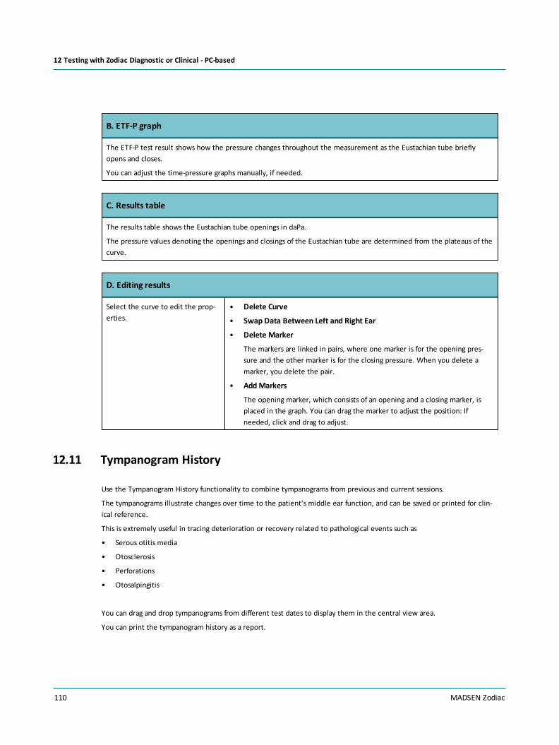
B. ETF-P graph
The ETF-P test result shows how the pressure changes throughout the measurement as the Eustachian tube brieflyopens and closes.
You can adjust the time-pressure graphs manually, if needed.
C. Results table
The results table shows the Eustachian tube openings in daPa.
The pressure values denoting the openings and closings of the Eustachian tube are determined from the plateaus of thecurve.
D. Editing results
Select the curve to edit the prop-erties.
• Delete Curve
• Swap Data Between Left and Right Ear
• Delete Marker
The markers are linked in pairs, where one marker is for the opening pres-sure and the other marker is for the closing pressure. When you delete amarker, you delete the pair.
• AddMarkers
The opening marker, which consists of an opening and a closing marker, isplaced in the graph. You can drag the marker to adjust the position: Ifneeded, click and drag to adjust.
12.11 Tympanogram History
Use the Tympanogram History functionality to combine tympanograms from previous and current sessions.
The tympanograms illustrate changes over time to the patient's middle ear function, and can be saved or printed for clin-ical reference.
This is extremely useful in tracing deterioration or recovery related to pathological events such as
• Serous otitis media
• Otosclerosis
• Perforations
• Otosalpingitis
You can drag and drop tympanograms from different test dates to display them in the central view area.
You can print the tympanogram history as a report.
110 MADSEN Zodiac
12 Testing with Zodiac Diagnostic or Clinical - PC-based

12.11.1 The Tymp History screen
Tymp History
Select tympanograms from different sessions
• Drag and drop tympanograms from different test dates for display in the central view area. The tym-panograms illustrate changes over time to the middle ear function.
The Tympanogram History screenshowing tympanograms ready for selec-tion.
MADSEN Zodiac 111
12 Testing with Zodiac Diagnostic or Clinical - PC-based

The Tympanogram History screenshowing tympanograms selected forcomparison.
112 MADSEN Zodiac
12 Testing with Zodiac Diagnostic or Clinical - PC-based

13 Managing test results in MADSEN ZodiacThe following applies to managing test results in MADSEN Zodiac. If you wish to perform these actions in Otosuite, see theOtosuiteUser Guide or OtosuiteReference Manual
Deletingmeasurements1. You can delete a single measurement curve by using the soft-button functions Previous Curve or Next Curve to select
the curve you wish to delete.
2. Press the Delete button.
MADSEN Zodiac 113
13 Managing test results in MADSEN Zodiac

14 Printing from ZodiacReport You can print out test results directly from Zodiac, if it is equipped with a
built-in printer.
Printing from the built-in printer1. If the device is configured to print directly from the built-in printer, press the Report button to print out the test res-
ults.
You can use the dial to scroll through the preview before printing.
2. Remember to write the patient's name on the print-out.
114 MADSEN Zodiac
14 Printing from Zodiac

15 Transferring data to OtosuiteYou can transfer data from Zodiac to Otosuite.
Report You can transfer data from Zodiac to a PC with Otosuite installed.
Transferring data to OtosuiteIf you need to change the patient in Otosuite, while you are working with Otosuite you can fetch the patient's test res-ults from Zodiac.
MADSEN Zodiac 115
15 Transferring data to Otosuite

16 Printing test results from OtosuiteUse the Otosuite print function to print a test report. See the Otosuite User Guide.
Tympanometry
• Click the checkboxes in the View column to select ordeselect the curves you wish to include in the test report.
116 MADSEN Zodiac
16 Printing test results from Otosuite

17 Service and maintenance
Warning•For the sake of safety and in order not to void the warranty, service and repair of electro-medical equip-ment should be carried out only by the equipment manufacturer or by service personnel at authorized workshops. Incase of any defects, make a detailed description of the defect(s) and contact your supplier. Do not use a defectivedevice.
Warning•Under no circumstances disassemble MADSEN Zodiac. Contact your supplier. Parts inside MADSEN Zodiacmust only be checked or serviced by authorized personnel.
Probe replacementThe Zodiac immittance probes (Quick Check and/or diagnostic probe) are connected permanently to the device.
Caution•A Zodiac probe should only be disconnected or replaced by an authorized service technician.
17.1 Equipment failure
If you believe the correct function or operation safety of the device to be faulty in any way, disconnect the device fromthe power supply and make sure that it cannot be used by others until it has been serviced.
Warning•For the sake of safety and in order not to void the warranty, service and repair of electro-medical equip-ment should be carried out only by the equipment manufacturer or by service personnel at authorized workshops. Incase of any defects, make a detailed description of the defect(s) and contact your supplier. Do not use a defectivedevice.
Warning•Under no circumstances disassemble MADSEN Zodiac. Contact your supplier. Parts inside MADSEN Zodiacmust only be checked or serviced by authorized personnel.
17.2 Service and repair
Warning•Under no circumstances disassemble MADSEN Zodiac. Contact your supplier. Parts inside MADSEN Zodiacmust only be checked or serviced by authorized personnel.
For the sake of safety and in order not to void the warranty, service and repair of electro-medical equipment should be car-ried out only by the equipment manufacturer or by service personnel at authorized workshops. In case of any defects,make a detailed description of the defect(s) and contact your supplier. Do not use a defective device.
MADSEN Zodiac 117
17 Service and maintenance

The manufacturer is to be considered responsible for effects on safety, reliability, and performance of the equipment onlyif:
• All assembly operations, extensions, re-adjustments, modifications or repairs are carried out by the equipment man-ufacturer or personnel authorized by the manufacturer.
• The electrical installation to which the equipment is connected complies with EN/IEC requirements.
• The equipment is used in accordance with the instructions for use.
The manufacturer reserves the right to disclaim all responsibility for the operating safety, reliability and performance ofequipment serviced or repaired by other parties.
On request, your supplier can obtain a Service Manual from the manufacturer.
17.3 Maintenance
MADSEN Zodiac requires no preventive maintenance. However, it is recommended that you observe the guidelinesdescribed in
Cleaning MADSEN Zodiac► 120 and Calibration► 118.
17.3.1 Calibration
Note •Calibration should always be performed in a low-noise environment.
The device and the probes are delivered fully calibrated.
• The device is calibrated from the factory in dB SPL or dB HL using the stated reference equivalent thresholds. dB HLare related to sound pressure levels, dB SPL = dB re 20 µPa.
• The probe calibration values are saved in the probe assembly and follows the probe. The probe can be plugged to anyMADSEN Zodiac and used right away. This also applies to the contra insert phone.
Probe checkThe diagnostic probe and the Quick Check, if supplied, should be checked daily.
See Probe check► 37.
Additional probe admittance checks can be performed. See the MADSEN Zodiac Reference Manual.
Note • If the test environment changes, for instance if there is an increase in humidity or if you are going to test at adifferent altitude, make a probe check to verify that the system measures correctly.
Annual calibration• The device and probe(s) must be calibrated once a year by your authorized service department.
• The Quick Check and diagnostic probes should be calibrated at least annually.
17.3.2 Probe admittance calibration
We recommend that you carry out this type of calibration at least once a year.
118 MADSEN Zodiac
17 Service and maintenance

Note • If the test environment changes, for instance if there is an increase in humidity or if you are going to test at adifferent altitude, make a probe check to verify that the system measures correctly.
You can calibrate Zodiac from the device or from Otosuite.
Standard equipment• Multi-frequency cavity kit (0.5 cc, 2.0 cc, 5.0 cc, HF)
Performing Probe Admittance Calibration from Zodiac1. Use a new probe tip, or make sure that the probe tip has been
cleaned and disinfected, before you place it in the test cavity.This is to make sure that the probe tip does not influence theprobe test, and that the test cavity is not contaminated.
2. To access Probe Admittance Calibration from MADSEN Zodiac,switch on the device and select Special > Calibration > ProbeAdmittance.
3. Select the probe type you wish to calibrate:Quick Check or Dia-gnostic.
4. When the probe light indicator shows that the probe is active,place the probe in the 0.5 cc test cavity of the multi-frequencycavity kit.
The calibration starts automatically.
5. A progress bar shows when the first calibration is done, and theprobe light indicator turns green.
6. Remove the probe from the cavity and wait until the probelight indicator shows that the probe is active.
7. Repeat the procedure with the 2.0 cc and the 5.0 cc cavities.
If you are calibrating a Quick Check probe, do not calibrate theprobe in the HF cavity.
When the probe has been measured in all four cavities, the admit-tance has been calibrated for the applicable frequencies.
If there is a probe errorIn case of a probe error, check the probe status for possible causes.
If the probe is faulty, contact an authorized service department forrepair.
MADSEN Zodiac 119
17 Service and maintenance

17.4 Cleaning MADSEN Zodiac
Caution•Make sure that you comply with local infection control regulations.
Cleaning agents
Caution•Use only the cleaning agents prescribed for cleaning the device.
See Recommended cleaning agents► 121.
FrequencyWe recommend that you set up a schedule for cleaning Zodiac and accessories such as probes and/or earphones.
Prerequisites• Before cleaning, switch off MADSEN Zodiac and disconnect it from any external power source.
• If needed, unplug the contralateral probe from MADSEN Zodiac.
Cleaning under the dial• If the device is a Zodiac Diagnostic or a Zodiac Clinical, use a thin cloth with a recommended cleaning agent to gently
the clean the area beneath it.
• If needed, use a screw driver (torq IP6) to carefully unscrew the screw fastening the dial.
Procedure
Warning•Keep the unit away from liquids. Do not allow moisture inside the unit. Moisture inside the unit can dam-age the instrument and it may result in a risk of electrical shock to the user or patient.
1. Clean the external surfaces of the device:
– Remove dust using a soft brush.
– Use a soft, slightly damp cloth with a small amount of cleaning agent to clean the external surfaces of the deviceaccording to local infection control regulations.
See the list of recommended cleaning agents.
2. Make sure that you have cleaned all surfaces, edges and crevices thoroughly.
3. Reconnect the contralateral probe, if needed.
120 MADSEN Zodiac
17 Service and maintenance

17.4.1 Recommended cleaning agents
Caution•Use only the cleaning agents prescribed for cleaning the device.
For cleaning the device, we recommend that you only use non-alcohol-based disinfectant wipes (e.g. Audio wipe) or acloth dampened lightly with a recommended cleaning agent to ensure proper infection control and maximum lifetime ofthe device.
The following chemical solutions are recommended:
Cabinet surface and probes• Non-alcohol-based disinfectant wipes (e.g. Audio wipe)
• Ammonium compounds (e.g. dimethyl benzyl ammonium chloride), in concentrations no stronger than 0.1 %.
• Aldehyde solutions (e.g. glutaraldehyde),
• Oxidizing agents (e.g. Hydrogen peroxide in concentrations no stronger than 3%)
• Ortho-phthalaldehyde in concentrations no stronger than 0.6 %.
Caution• If plastic parts are soaked in a cleaning agent they will deteriorate.
17.4.2 Cleaning the device
Caution•Use only the cleaning agents prescribed for cleaning the device.
Procedure
Warning•Keep the unit away from liquids. Do not allow moisture inside the unit. Moisture inside the unit can dam-age the instrument and it may result in a risk of electrical shock to the user or patient.
1. Clean the external surfaces of the device:
– Remove dust using a soft brush.
– Use a soft, slightly damp cloth with a small amount of cleaning agent to clean the external surfaces of the deviceaccording to local infection control regulations.
See the list of recommended cleaning agents.
2. Make sure that you have cleaned all surfaces, edges and crevices thoroughly.
3. Reconnect the contralateral probe, if needed.
MADSEN Zodiac 121
17 Service and maintenance

Cleaning under the dial• If the device is a Zodiac Diagnostic or a Zodiac Clinical, use a thin cloth with a recommended cleaning agent to gently
the clean the area beneath it.
• If needed, use a screw driver (torq IP6) to carefully unscrew the screw fastening the dial.
The display• Use an anti-static non-solvent solution on a lint-free cloth.
17.4.3 Cleaning the shoulder strap
Use a soft, slightly damp cloth with a small amount of cleaning agent to clean the shoulder strap and control pad.
You can remove the shoulder strap from the control pad, If you need to clean the shoulder strap more thoroughly.
17.4.4 Cleaning the probe and probe tip
Although the probes are designed to be easily cleaned, care should be taken to make sure that they last a long time.
Note •Check the sound channels in the probe tip every time you have used the probe.Even small amounts of cerumenor vernix can block the sound channels. Clean the sound channels if needed.
Note •Accurate testing is only guaranteed if you use the eartips approved specifically for MADSEN Zodiac by Oto-metrics.
Ear canal debris blocking the probe tubes can lead to abnormally large ear canal volume readings, leak messages, and otherodd results. Check the channels of the probe tip every time you use the probe. Even small amounts of cerumen or vernixcan block the probe channels.
Warning•Fit a new probe tip on the probe if you have been testing on an infected ear canal. Cleaning the probe ringmay also be necessary.
Cleaning the probe• Wipe the probe with a disinfectant wipe, such as Audio-wipes, between patients or replace it with a spare one.
• Wipe the cable with a disinfectant wipe, such as Audio-wipes.
• Wipe the probe home with a disinfectant wipe, such as Audio-wipes.
Cleaning or replacing the probe tipIf the probe tip is only slightly blocked, use the probe tip flossing thread to clean the probe tip channels.
Note •Always comply with local hygienic standards for disinfection.
122 MADSEN Zodiac
17 Service and maintenance

A. Probe bodyB. Probe ringC. Probe tip
1. To remove the probe tip, hold the probe bythe probe body and twist the probe ringslightly counter-clockwise. This will loosen theprobe tip.
Caution•Even the slightest amount of mois-ture may dissolve any residual cerumen andthus contaminate the sensitive parts in thebody of the probe.
2. Take out the probe tip.
MADSEN Zodiac 123
17 Service and maintenance

3. Check to see if the sound channels of the probetip are blocked. You can fit a new probe tip onthe probe, or use the supplied probe tipflossing thread to clean the sound channels.
Caution•Never clean the sound channels inthe probe body, as this may cause damage tothe probe. A. Sound channels
4. Fit the probe tip on the probe, and twist theprobe ring clockwise to lock the probe tip inplace on the probe.
Probe checkIf you have fitted a new probe tip, do a probe check. See Probe check► 37.
17.4.5 Fitting a new probe tip
If the probe tip has been contaminated or blocked by cerumen or vernix, fit a new probe tip on the probe.
Procedure
A. Probe bodyB. Probe ringC. Probe tip
124 MADSEN Zodiac
17 Service and maintenance

1. To remove the probe tip, hold the probe bythe probe body and twist the probe ringslightly counter-clockwise. This will loosen theprobe tip.
Caution•Even the slightest amount of mois-ture may dissolve any residual cerumen andthus contaminate the sensitive parts in thebody of the probe.
2. Take out the probe tip.
3. Fit the probe tip on the probe, and twist theprobe ring clockwise to lock the probe tip inplace on the probe.
If you intend to test using probe tones higher than 226 Hz, we recommend that you make a probe admittance calibrationafter changing the probe tip. See Probe admittance calibration► 118.
Probe checkIf you have fitted a new probe tip, do a probe check. See Probe check► 37.
17.4.6 Cleaning the test cavities
If a test cavity becomes contaminated, do not use it. Dispose of it and replace it with a new one.
17.4.7 Cleaning the printer
Check the paper compartment regularly to make sure that it is free from paper dust and that the thermal paper head isclean.
Prerequisites• Before cleaning, switch off MADSEN Zodiac and disconnect it from any external power source.
Warning•When you open the paper compartment, be careful not to injure your hands on the cutter blades.
Caution•When you clean the paper compartment, never use metal objects or liquids.
MADSEN Zodiac 125
17 Service and maintenance

Cleaning the paper compartment1. To remove paper dust, use canned compressed air to clean the compartment. Do not use liquids to clean the paper
compartment.
2. If the thermal print head or platen needs cleaning, contact an authorized service technician.
17.4.8 Disposable accessories
Some accessories, such as disposable eartips and foam eartips for insert phones, are in direct contact with the patient, andyou should therefore observe strict hygienic precautions to prevent passing infection from one patient to another.
Disposable accessories should not be cleaned or re-used. Always throw away disposable accessories after use on a patient.
EartipsTo prevent cross-infection, use new eartips when you test the next client.
• Use only disposable eartips.
• Dispose of eartips after use.
Probe tip cleaning kitThe probe tip cleaning kit contains a specific type of flossing thread well suited for cleaning the probe tip.
• Dispose of the flossing thread after cleaning the probe tip.
DisposalThere are no special requirements for the disposal of disposable articles such as eartips and probe tip cleaning floss, i.e.they can be discarded according to local regulations.
126 MADSEN Zodiac
17 Service and maintenance

18 Standards and safetyThis manual contains information and warnings, which must be followed to ensure the safe performance of the devices andsoftware covered by this manual. Local government rules and regulations, if applicable, should also be followed at all times.
See Symbols used► 127 and Warning notes► 128.
18.1 Symbols used
MADSEN Zodiac complies with the standards listed below.
MADSEN Zodiac
Type BF applied part
Complies with Type BF requirements of IEC 60601-1.
Follow instructions for use
Caution
Indicates the need for the user to consult the instructions for use for important cautionary informationsuch as warnings and precautions that cannot, for a variety of reasons, be presented on the medical deviceitself.
CE marking of conformity
Certification mark that indicates conformity with applicable regulations and directives for the EuropeanEconomic Area.
Complies with the Radio Equipment and Telecommunications Terminal Equipment Directive 1999/5/EC.
ManufacturerIndicates the medical device manufacturer, as defined in EU Directives 90/385/EEC,93/42/EEC and 98/79/EC.
Serial numberIndicates the manufacturer’s serial number so that a specific medical device can beidentified.
Catalog/product numberIndicates the manufacturer’s catalogue number so that the medical device can beidentified.
MEDICAL - General Medical Equipment as to electrical shock, fire and mechanical hazards only in accord-ance with:
ANSI/AAMI ES60601-1:2005/(R)2012
IEC 60601-1-6
CAN/CSA-C22.2 No. 60601-1:14
CAN/CSA-C22.2 No. 60601-1-6
In France, it is only permitted to use the device indoors.
MADSEN Zodiac 127
18 Standards and safety
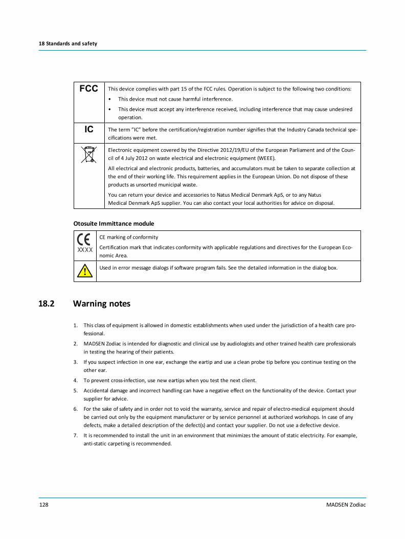
This device complies with part 15 of the FCC rules. Operation is subject to the following two conditions:
• This device must not cause harmful interference.
• This device must accept any interference received, including interference that may cause undesiredoperation.
The term ”IC” before the certification/registration number signifies that the Industry Canada technical spe-cifications were met.
Electronic equipment covered by the Directive 2012/19/EU of the European Parliament and of the Coun-cil of 4 July 2012 on waste electrical and electronic equipment (WEEE).
All electrical and electronic products, batteries, and accumulators must be taken to separate collection atthe end of their working life. This requirement applies in the European Union. Do not dispose of theseproducts as unsorted municipal waste.
You can return your device and accessories to Natus Medical Denmark ApS, or to any NatusMedical Denmark ApS supplier. You can also contact your local authorities for advice on disposal.
Otosuite Immittance module
CE marking of conformity
Certification mark that indicates conformity with applicable regulations and directives for the European Eco-nomic Area.
Used in error message dialogs if software program fails. See the detailed information in the dialog box.
18.2 Warning notes
1. This class of equipment is allowed in domestic establishments when used under the jurisdiction of a health care pro-fessional.
2. MADSEN Zodiac is intended for diagnostic and clinical use by audiologists and other trained health care professionalsin testing the hearing of their patients.
3. If you suspect infection in one ear, exchange the eartip and use a clean probe tip before you continue testing on theother ear.
4. To prevent cross-infection, use new eartips when you test the next client.
5. Accidental damage and incorrect handling can have a negative effect on the functionality of the device. Contact yoursupplier for advice.
6. For the sake of safety and in order not to void the warranty, service and repair of electro-medical equipment shouldbe carried out only by the equipment manufacturer or by service personnel at authorized workshops. In case of anydefects, make a detailed description of the defect(s) and contact your supplier. Do not use a defective device.
7. It is recommended to install the unit in an environment that minimizes the amount of static electricity. For example,anti-static carpeting is recommended.
128 MADSEN Zodiac
18 Standards and safety

8. We recommend that the device should not be stacked with other equipment or placed in a poorly ventilated space asthis may affect the performance of the device. If it is stacked or placed adjacent to other equipment, make sure thatthe operation of the device is not affected.
9. Do not store or operate the device at temperatures and humidity exceeding those stated in the Technical Spe-cifications, Transport and storage.
10. Keep the unit away from liquids. Do not allow moisture inside the unit. Moisture inside the unit can damage theinstrument and it may result in a risk of electrical shock to the user or patient.
11. Do not use the instrument in the presence of flammable agents (gases) or in an oxygen-rich environment.
12. No parts may be eaten, burnt, or in any way used for purposes other than the applications defined in the Intended Usesection of this manual.
13. Choking hazard! Do not leave eartips unsupervised within the reach of children.
14. The device and any device to be connected which has its own power supply should be turned off before any con-nections are established. To disconnect the device from the mains supply, pull the mains plug out of the wall mainsoutlet. Do not position the unit so that it is difficult to pull the mains plug out of the wall mains.
15. For safety reasons and due to effects on EMC, accessories connected to the equipment's outlet fittings must beidentical to the type supplied with the system.
16. It is recommended that an annual calibration be performed on accessories containing transducers. Furthermore, it isrecommended that calibration be performed if the equipment has suffered any potential damage (e.g. headphones,contraphones, probes dropped on the floor).
Note that calibration has been performed only on the transducers supplied! If you wish to use any other transducer fortesting with the device, please contact your local distributor first.
17. Disposable accessories, such as eartips, should not be reused and must be replaced between patients to prevent cross-infection.
18. Unwanted noise may occur if the instrument is exposed to a strong radio field. Such noise may interfere with the pro-cess of recording correct measurements. Many types of electrical devices, e.g. mobile telephones, may generate radiofields. We recommend that the use of such devices in the vicinity of this instrument be restricted as much as possible.
Likewise, we recommend that the instrument is not used in the vicinity of devices sensitive to electromagnetic fields.
19. Changes or modifications not expressly approved by the manufacturer could void the user's authority to operate theequipment.
20. The device and power supply can be disposed of as normal electronic waste, according to local regulations.
21. Use only the specified power supply.
See Technical Specifications, Power supply.
When assembling an electro-medical system, the person carrying out the assembly must take into accountthat other connected equipment which does not comply with the same safety requirements as this product(e.g. PC and/or printer) may lead to a reduction in the overall safety level of the system. The equipmentmust comply with UL/IEC 60950.
When selecting accessories connected to the device, the following points must be considered:• Use of connected equipment in a patient environment.
• Proof that connected equipment has been tested in accordance with IEC 60601-1 (3rd), AAMI ES60601-1and CAN/CSA-C22.2 NO. 60601-1-08-CAN/CSA.
Do not touch the output DC plug of the power supply or connectors of the device or connected devices andthe patient at the same time.
MADSEN Zodiac 129
18 Standards and safety

22. To comply with IEC 60601-1(3rd) computer and printer must be placed out of reach of the client, i.e. not closer thanapprox. 1.5 meters/5 ft.
23. This equipment has been tested and found to comply with the limits for a Class B digital device, pursuant to part 15 ofthe FCC Rules. These limits are designed to provide reasonable protection against harmful interference in a residentialinstallation. This equipment generates, uses and can radiate radio frequency energy and, if not installed and used inaccordance with the instructions, may cause harmful interference to radio communications. However, there is no guar-antee that interference will not occur in a particular installation. If this equipment does cause harmful interference toradio or television reception, which can be determined by turning the equipment off and on, the user is encouragedto try to correct the interference by one or more of the following measures:
– Increase the separation between the equipment and receiver.
– Connect the equipment into an outlet on a circuit different from that to which the receiver is connected.
– Consult the dealer or an experienced radio/TV technician for help.
18.3 Manufacturer
Natus Medical Denmark ApSHoerskaetten 9, 2630 TaastrupDenmark
+45 45 75 55 55www.natus.com
18.3.1 Responsibility of the manufacturer
The manufacturer is to be considered responsible for effects on safety, reliability, and performance of the equipment onlyif:
• All assembly operations, extensions, re-adjustments, modifications or repairs are carried out by the equipment man-ufacturer or personnel authorized by the manufacturer.
• The electrical installation to which the equipment is connected complies with EN/IEC requirements.
• The equipment is used in accordance with the instructions for use.
The manufacturer reserves the right to disclaim all responsibility for the operating safety, reliability and performance ofequipment serviced or repaired by other parties.
130 MADSEN Zodiac
18 Standards and safety

19 Technical specificationsType identification
MADSEN Zodiac is type 1096 from Natus Medical Denmark ApS
Compliance measuring system
Probe tone: 226 Hz at 85 dB SPL ± 3 dB678 Hz at 72 dB SPL ± 3 dB800 Hz at 70.5 dB SPL ± 3 dB1000 Hz at 69 dB SPL ± 3 dB
Dynamic probe tone level: The probe tone level will be compensated to accommodate varying ear canalvolumes.
The output level will be decreased in volumes < 1.7 ml
The output level will be increased in volumes > 2.3 ml
THD: < 1% in 2 cc
Frequency accuracy: ± 0.5%
Range: 0.2 ml to 5.0 ml ± 5% or 0.05 ml whichever is greater *
5.0 ml to 8.0 ml ± 15% *
* The accuracy stated requires that calibration has been performed at the alti-tude where the device is to be put into operation
Acoustic reflex
Sensitivity
Reflex Threshold and Reflex Decay: 0.01, 0.02, 0.03, 0.04 or 0.05 mmho
Reflex Screening: 0.04 mmho
Step size dB: Quick Check: 10 dB
Diagnostic: 5, 10 dB Clinical: 1, 2, 5, 10 dB
Contralateral Stimulation
Pure tones: 500 Hz, 1000 Hz, 2000 Hz, 4000 Hz
Frequency accuracy: ± 0.5%
Range: BBN, LPN, HPN at 50 to 110 dB SPL * ±3 dB
* measured in the respective couplers
Contralateral insert phone: Contralateral TDH-39 phone:
Range: 500 Hz at 50 to 115 dB HL ± 3 dB1000 Hz at 50 to 120 dB HL ± 3 dB2000 Hz at 50 to 120 dB HL ± 3 dB4000 Hz at 50 to 120 dB HL ± 3 dB
500 Hz at 50 to 115 dB HL ± 3 dB1000 Hz at 50 to 120 dB HL ± 3 dB2000 Hz at 50 to 115 dB HL ± 3 dB4000 Hz at 50 to 115 dB HL ± 3 dB
MADSEN Zodiac 131
19 Technical specifications

THD: < 5% for levels below 110 dB HL
< 10% for levels above 110 dB HL
< 2.5 % for levels below 110 dB HL
< 5 % for levels above 110 dB HL
Ipsilateral Stimulation
Tone: 500 Hz, 1000 Hz, 2000 Hz, 4000 Hz
Frequency accuracy: ± 0.5%
Threshold range: 500 Hz at 50 to 105 dB HL ± 3 dB1000 Hz at 50 to 110 dB HL ± 3 dB2000 Hz at 50 to 110 dB HL ± 3 dB *4000 Hz at 50 to 100 dB HL ± 3 dB
* For probe tones above 226 Hz, artifacts may start to occur at levels above105 dB HL
Screening range: 500 Hz at 70 to 100 dB HL ± 3 dB1000 Hz at 70 to 105 dB HL ± 3 dB2000 Hz at 70 to 105 dB HL ± 3 dB *4000 Hz at 70 to 105 dB HL ± 3 dB
* For probe tones above 226 Hz, artifacts may start to occur at levels above105 dB HL
THD: < 5% for levels below 110 dB HL
< 10% for levels above 110 dB HL
Range: BBN, LPN, HPN at 50 to 110 dB SPL * ±3 dB (* measured in calibrationcoupler)
Screening range: BBN at 50 to 90 dB SPL * ±3 dB (* measured in calibration coupler)
Step size dB: 1, 2, 5, 10 dB
Decay range: 50 to 100 dB HL* (* artifacts may start to occur at levels above 95 dB HL in 0.5cc)
Temporal characteristics
Reflex Decay, ContralateralReflex Threshold and Screen-
ing
Ipsilateral Reflex Thresholdand Screening
Contralateral stimulation -Probe tone > 226 Hz
Initial/terminal latency: 0 ms 0 ms [1] 0 ms
Rise/fall time: 250 ms 250 ms [1] 100 ms
Overshoot/Undershoot: 0 % 0% 0%
Notes:1. Tolerance +120/-0 ms
132 MADSEN Zodiac
19 Technical specifications

Characteristics for pulsed stimuli (ipsilateral)
Pulsed stimuli are used for ipsilateral Reflex Screening and Reflex Threshold testing.
Period: 120 ms
Stimulus On time: 56 ms
Stimulus Off time: 64 ms
Rise/fall time: 5.5 ms
Stimulus presentation control
On-Off ratio: 70 dB (for stimulus level > 95 dB HL)
A weighted SPL in Off: Contra supra-aural TDH 39: 33 dB
Contra insert phone: 23 dB
Tympanometry accuracy description (daPa/s)
Pump speed Min.TW, 5% error(daPa)
Min. TW, 10% error(daPa)
Min. SA, 5% error(daPa)
Min. SA, 10% error(daPa)
50 daPa/s 9 7 6 4
100 daPa/s 17 14 11 8
200 daPa/s 24 20 18 14
400 daPa/s 38 31 31 23
600 daPa/s 53 43 42 32
Broadband noise
Contralateral TDH-39 headphone
Bandwidth: 250 - 6000 Hz. Tolerance ±5 dB re. 1 kHz level.
Slope: Spectrum level drops between 6000 and 9500 Hz and remains below -23 dBre. 1 kHz level for frequencies above 9500 Hz.
Level: Noise level is indicated in dB HL. Tolerance ±5 dB.
Contralateral insert earphone and ipsilateral probe
Bandwidth: 400 - 4000 Hz. Tolerance ±5 dB re. 1 kHz level.
Slope: Spectrum level drops between 4000 and 7000 Hz and remains below -23 dBre. 1 kHz level for frequencies above 7000 Hz.
Level: Noise level is indicated in dB HL. Tolerance ±5 dB.
MADSEN Zodiac 133
19 Technical specifications

Lowpass noise
Contralateral TDH-39 headphone
Band limit: 1600 Hz (nominal -3 dB point)
Slope: The slope is between -12 and -18 dB/octave above 1600 Hz, with an additional±6 dB tolerance. Above 8500 Hz, the spectrum level remains below -34 dB re.1600 Hz level.
Level: Noise level is indicated in dB HL. Tolerance ±5 dB.
Contralateral insert earphone and ipsilateral probe
Bandwidth: 1600 Hz (nominal -3 dB point)
Slope: The slope is between -12 and -18 dB/octave above 1600 Hz, with an additional±6 dB tolerance. Above 8500 Hz, the spectrum level remains below -34 dB re.1600 Hz level.
Level: Noise level is indicated in dB HL. Tolerance ±5 dB.
Highpass noise
Contralateral TDH-39 headphone
Band limit: 1600 Hz (nominal -3 dB point)
Slope: The slope is between +12 and +18 dB/octave below 1600 Hz, with an addi-tional ±6 dB tolerance.
Level: Overall noise level is indicated in dB HL. Tolerance ±5 dB.
Contralateral insert earphone and ipsilateral probe
Bandwidth: 1600 Hz (nominal -3 dB point)
Slope: The slope is between +12 and +18 dB/octave above 1600 Hz, with an addi-tional ±6 dB tolerance.
Level: Noise level is indicated in dB HL. Tolerance ±5 dB.
ANSI & IEC reflex stimulus RETSPL values
Frequencies(Hz)
Ipsilateral probeHA-1 [2]
InsertphoneHA-1 [2]
InsertphoneHA-2 [2]
Supra-auralphoneIEC 60318-3/NBS 9A[1]
Supra-auralphoneIEC 60318-1[1]
500 6.0 6.0 5.5 11.5 13.5
1000 0.0 0.0 0.0 7.0 7.5
2000 2.5 2.5 3.0 9.0 9.0
4000 0.0 0.0 5.5 9.5 12.0
134 MADSEN Zodiac
19 Technical specifications

BBN [3] 6.5 6.0 8.0 12.0 13.5
LBN [3] 7.5 9.5 8.5 10.5 11.5
HBN [3] 4.0 5.0 7.5 12.5 14.5
Notes:1. From ANSI/ASA S3.6-2010, Table 5.
2. From ANSI/ASA S3.6-2010, Table 7.
3. Based on Otometrics internal study
Air pressure system
Range: Normal +200 to -400 daPa/s. Extended +400 to -600 daPa/s
Pressure sweep rate: 50, 100, 200, 400, 600 daPa/s ± 20% in 20% to 80% of the total pressure range
Pressure accuracy: ± 10% or ± 10 daPa, whichever is greatest
For probe tones above 226 Hz and volumes below 0.7 cc, additional ± 10 daPacan occur.
Pump measure direction: Positive to negative or negative to positive
Safety: Separate safety +530 daPa and -730 daPa ±70 daPa
Graph units
Unit of admittance graph Y-axis: ml, cc, mmho, µl
Unit of graph X-axis: daPa, sec
Device display
Display: 7 inch, 15:9 WVGA
Resolution: 800 x 480 pixel
USB port connector
Type: USB device port
Power supply
External power supply XP Power, type AFM60US24
Output: 24 V, 2.5 A
Input: 100-240 V AC, 50-60 Hz, 1.5 A
Power consumption
Power consumption: < 70 VA
MADSEN Zodiac 135
19 Technical specifications

Operating environment
Temperature: +15°C to +35°C (59°F to +95°F)
Air humidity: 10 to 90%, non-condensing
Air pressure: 600 hPa to 1060 hPa
Warm-up time: < 10 min. If stored in conditions not within specified operating environmentconditions, the device must warm up for 24 hour before being put into oper-ation.
Altitude correctionThe admittance of a cavity depends on the atmospheric pressure. This means that when the atmospheric pressure changes,the relation between mmho and ml changes. The following table can be used to calculate the difference.
Altitude (m) Increase in mmho (%)
0 0
500 6
1000 13
1500 20
2000 27
2500 36
3000 45
Storage and handling
Temperature: -20°C to +60°C (-4°F to +140°F)
Relative humidity: < 90 %, non-condensing
Air pressure: 500 hPa to 1060 hPa
Dimensions (HxWxD)
Stand-alone version: 190 mm x 248 mm x 261 mm (7.5” x 9.8” x 10.3”)
PC-based version: 100 mm x 240 mm x 240 mm (3.9” x 9.4” x 9.4”)
Probe dimensions (HxWxD)
Quick Check probe: 28 mm x 22 mm x 100 mm (1.1” x 0.9” x 3.9”)
Diagnostic probe: 10 mm x 10 mm x 25 mm (0.4” x 0.4” x 1.0”)
Weight
Stand-alone version: 2.65 kg/5.85 lb
PC-based version: 1.65 kg/3.64 lb
136 MADSEN Zodiac
19 Technical specifications

Optional features (Stand-alone)
Printer: Built-in printer. Prints 832 dot line/s on 112 mm paper width
2 cc coupler
Calibration
Equipment should be calibrated regularly according to EN 60645-5 and ANSI S3.39
Essential performanceMADSEN Zodiac has no essential performance and accordingly, the applicable requirements are as stated in the following:
1. Impedance/admittance as defined by EN 60645-5:2005 Type 1, ANSI S3.39 1987 (R2012) Type 1
EN 60645-5:2005 Type 2, ANSI S3.39 1987 (R2012) Type 2
2. Basic safety as defined by IEC 60601-1:2005+AMD1:2012 and EN 60601-1:2006+A1:2013
3. Electromagnetic compatibility as defined by IEC 60601-1-2:2007 and EN 60601-1-2:2007
IEC 60601-1-2:2014 and EN 60601-1-2:2015
Standards
Safety: IEC 60601-1:2005+AMD1:2012EN 60601-1:2006+A1:2013
ANSI/AAMI ES60601-1:2005 + A1:2012
CAN/CSA-C22.2 NO. 60601-1:14
Class II, externally powered, Type BF, IPX0
EMC: IEC 60601-1-2:2007 and EN 60601-1-2:2007
IEC 60601-1-2:2014 and EN 60601-1-2:2015
Impedance/Admittance: Clinical/Diagnostic: EN 60645-5:2005 Type 1, ANSI S3.39 1987 (R2012) Type 1
Quick Check: EN 60645-5:2005 Type 2, ANSI S3.39 1987 (R2012) Type 2
Power supply: Class I, externally powered supply
Disposal
MADSEN Zodiac can be disposed of as normal electronic waste, according to WEEE and local regulations.
MADSEN Zodiac 137
19 Technical specifications

20 Accessories• Diagnostic probe, Classic
• Diagnostic probe, Comfort
• Quick Check probe
• Eartips
• Eartip box
• Otometrics insert phone, contralateral
• Contralateral phone, TDH-39
• Inserts for contralateral phones
• Shoulder strap hook
• Probe home for Quick Check probe, wall-mounted or device-mounted
• 2 cc cavity for probe check
• Multi-frequency cavity kit
• Otosuite SW installation disk
• Power cord
• MADSEN Zodiac User Guide
• MADSEN Zodiac Reference Manual
• USB connection cable
• Power supply unit
• Paper roll for built-in printer
• Probe tips
• Wall-mount kit for PC-based device
• Probe cleaning kit
138 MADSEN Zodiac
20 Accessories

21 Notes on EMC (Electromagnetic Compatibility)• MADSEN Zodiac is part of a medical electrical system and is thus subject to special safety precautions. For this reason,
the installation and operating instructions provided in this document should be followed closely.
• Portable and mobile high-frequency communication devices, such as mobile phones, may interfere with the func-tioning of MADSEN Zodiac.
IEC 60601-1-2:2014 and EN 60601-1-2:2015
Guidance and manufacturer's declaration - electromagnetic emissions for all equipment and systems
MADSEN Zodiac is intended for use in the electromagnetic environment specified below. The user of MADSEN Zodiac should ensure that it is used in such an
environment.
Emissions test Compliance Electromagnetic environment - guidance
RF emissions
CISPR11
Group 1 MADSEN Zodiac uses RF energy only for its internal function. Therefore, its RF emissions are very
low and are not likely to cause any interference in nearby electronic equipment.
RF emissions
CISPR11
Class B MADSEN Zodiac is suitable for use in all environments, including domestic environments and
those directly connected to the public low-voltage power supply network that supplies buildings
used for domestic purposes.Harmonic emissions IEC
61000-3-2
Not applicable
Voltage fluctuations/flicker
emissions IEC 61000-3-3
Not applicable
Guidance and manufacturer's declaration - electromagnetic immunity for all equipment and systems
MADSEN Zodiac is intended for use in the electromagnetic environment specified below. The user of MADSEN Zodiac should ensure that it is used in such an
environment.
Immunity test IEC 60601
test level
Compliance level Electromagnetic environment - guidance
Electrostatic discharge (ESD)
IEC 61000-4-2
+/- 8 kV contact
+/- 2 kV, +/- 4 kV,
+/- 8 kV, +/- 15 kV air
+/- 8 kV contact
+/- 2 kV, +/- 4 kV,
+/- 8 kV, +/- 15 kV air
Floors should bewood, concrete or ceramic tile. If floors
are covered with synthetic material, the relative humid-
ity should be at least 30%.
Electrical fast transient/burst
IEC 61000-4-4
+/- 2 kV for power supply lines
+/- 1 kV for input/output lines
+/- 2 kV for power supply lines
+/- 1 kV for input/output lines
Mains power quality should be that of a typical com-
mercial or hospital environment.
Surge
IEC 61000-4-5
+/- 1 kV line(s) to line(s)
+/- 2 kV line(s) to earth
+/- 2 kV DC input line(s) to earth
+/- 1 kV DC input line(s) to line(s)
+/- 2 kV I/O line(s) to earth
+/- 1 kV line(s) to line(s)
+/- 2 kV line(s) to earth
+/- 2 kV DC input line(s) to earth
+/- 1 kV DC input line(s) to line(s)
+/- 2 kV I/O line(s) to earth
Mains power quality should be that of a typical com-
mercial or hospital environment.
MADSEN Zodiac 139
21 Notes on EMC (Electromagnetic Compatibility)

Voltage dips, short inter-
ruptions and voltage vari-
ations on power supply input
lines
IEC 61000-4-11
0%UT; 0.5 cycleAt 0°, 45°, 90°, 135°, 180°, 225°, 270°
and 315°
0%UT; 1 cycleand
70%UT; 25/30 cyclesSingle phase: at 0°
0%UT; 0.5 cycleAt 0°, 45°, 90°, 135°, 180°, 225°, 270°
and 315°
0%UT; 1 cycleand
70%UT; 25/30 cyclesSingle phase: at 0°
Mains power quality should be that of a typical com-
mercial or hospital environment. If the user of the
MADSEN Zodiac requires continued operation during
power mains interruptions, it is recommended that the
MADSEN Zodiac be powered from an uninterruptible
power supply or a battery.
Voltage interruptions on
power supply input lines
IEC 61000-4-11
0%UT; 250/300 cycles 0%UT; 250/300 cycles
Power frequency
(50/60Hz) magnetic field
IEC 61000-4-8
30A/m No relevant ports that could be
affected
Power frequency magnetic fields should be at levels char-
acteristic of a typical location in a typical commercial or
hospital environment.
UT is the AC mains voltage prior to application of the test level.
Guidance and manufacturer's declaration - electromagnetic immunity - for equipment and systemswithin Professional Healthcare use environment
MADSEN Zodiac is intended for use in the electromagnetic environment specified below. The user of MADSEN Zodiac should ensure that it is used in such an
environment.
Immunity test IEC 60601
test level
Compliance level Electromagnetic environment - guidance
Conducted RF
IEC 61000-4-6
3V rms
150 kHz to 80MHz6V rms
ISMBands and Amateur
3 V rms
150 kHz to 80MHz6V rms
ISMBands and Amateur
Radiated RF
IEC 61000-4-3
10V/m
80MHz to 2.7GHz
10V/m
80MHz to 2.7GHz
Proximity fields from RF wire-
less communications
IEC 61000-4-3
27V/m
385MHz
28V/m
450MHz
9V/m
710MHz, 745MHz, 780MHz
28V/m
810MHz, 870MHz, 930MHz
28V/m
1720MHz, 1845MHz, 1970MHz
28V/m
2450MHz,
9 V/m
5240MHz, 5500MHz, 5785MHz
27V/m
385MHz
28V/m
450MHz
9V/m
710MHz, 745MHz, 780MHz
28V/m
810MHz, 870MHz, 930MHz
28V/m
1720MHz, 1845MHz, 1970MHz
28V/m
2450MHz,
9 V/m
5240MHz, 5500MHz, 5785MHz
Separation distance between any electronic parts of
MADSEN Zodiac and any RF wireless communication
equipment must bemore than 30 cm (11.8 inches).
Note: These guidelinesmay not apply in all situations.
Electromagnetic propagation is affected by absorption
and reflection from structures, objects and people.
140 MADSEN Zodiac
21 Notes on EMC (Electromagnetic Compatibility)

IEC 60601-1-2:2007 and EN 60601-1-2:2007
Guidance and manufacturer's declaration - electromagnetic emissions for all equipment and systems
MADSEN Zodiac is intended for use in the electromagnetic environment specified below. The user of MADSEN Zodiac should ensure that it is used in such an
environment.
Emissions test Compliance Electromagnetic environment - guidance
RF emissions
CISPR11
Group 1 MADSEN Zodiac uses RF energy only for its internal function. Therefore, its RF emissions are very
low and are not likely to cause any interference in nearby electronic equipment.
RF emissions
CISPR11
Class B MADSEN Zodiac is suitable for use in all environments, including domestic environments and
those directly connected to the public low-voltage power supply network that supplies buildings
used for domestic purposes.Harmonic emissions IEC
61000-3-2
Not applicable
Voltage fluctuations/flicker
emissions IEC 61000-3-3
Not applicable
Guidance and manufacturer's declaration - electromagnetic immunity for all equipment and systems
MADSEN Zodiac is intended for use in the electromagnetic environment specified below. The user of MADSEN Zodiac should ensure that it is used in such an
environment.
Immunity test IEC 60601
test level
Compliance level Electromagnetic environment - guidance
Electrostatic discharge (ESD)
IEC 61000-4-2
+/- 6 kV contact
+/- 8 kV air
+/- 6 kV contact
+/- 8 kV air
Floors should bewood, concrete or ceramic tile. If floors
are covered with synthetic material, the relative humid-
ity should be at least 30%.
Electrical fast transient/burst
IEC 61000-4-4
+/- 2 kV for power supply lines
+/- 1 kV for input/output lines
+/- 2 kV for power supply lines
+/- 1 kV for input/output lines
Mains power quality should be that of a typical com-
mercial or hospital environment.
Surge
IEC 61000-4-5
+/- 1 kV line(s) to line(s)
+/- 2 kV line(s) to earth
+/- 1 kV line(s) to line(s)
+/- 2 kV line(s) to earth
Mains power quality should be that of a typical com-
mercial or hospital environment.
Voltage dips, short inter-
ruptions and voltage vari-
ations on power supply input
lines
IEC 61000-4-11
<5%UT (>95% dip in UT) for0.5 cycle
40%UT (60% dip in UT) for 5cycles
70%UT (30% dip in UT) for 25cycles
<5%UT (>95% dip in UT) for 5s
<5%UT (>95% dip in UT) for0.5 cycle
40%UT (60% dip in UT) for 5cycles
70%UT (30% dip in UT) for 25cycles
<5%UT (>95% dip in UT) for 5s
Mains power quality should be that of a typical com-
mercial or hospital environment. If the user of the
MADSEN Zodiac requires continued operation during
power mains interruptions, it is recommended that the
MADSEN Zodiac be powered from an uninterruptible
power supply or a battery.
Power frequency
(50/60Hz) magnetic field
IEC 61000-4-8
3A/m 3A/m Power frequency magnetic fields should be at levels char-
acteristic of a typical location in a typical commercial or
hospital environment.
UT is the AC mains voltage prior to application of the test level.
MADSEN Zodiac 141
21 Notes on EMC (Electromagnetic Compatibility)

Guidance and manufacturer's declaration - electromagnetic immunity - for equipment and systems that areNOT life-supporting
MADSEN Zodiac is intended for use in the electromagnetic environment specified below. The user of MADSEN Zodiac should ensure that it is used in such an
environment.
Immunity test IEC 60601
test level
Compliance level Electromagnetic environment - guidance
Conducted RF
IEC 61000-4-6
3V rms
150 kHz to 80MHz
3V rms
150 kHz to 80MHz
Portable and mobile RF communications equipment
should be used no closer to any part of MADSEN Zodiac,
including cables, than the recommended separation dis-
tance calculated from the equation applicable to the fre-
quency of the transmitter.
Recommended separation distance:
d = 1.2
d = 1.2 for 80MHz to 800MHz
d = 2.3 for 80MHz to 2.5GHz,
whereP is themaximum output power rating of the
transmitter in watts (W) according to the transmitter
manufacturer and d is the recommended separation dis-
tance in metres (m).
Field strengths from fixed RF transmitters, as determ-
ined by an electromagnetic site survey, a should be less
than the compliance level in each frequency range. b
Interferencemay occur in the vicinity of equipment
marked with this symbol:
Radiated RF
IEC 61000-4-3
3V/m
80MHz to 2.5GHz
3V/m
80MHz to 2.5GHz
Note 1: At 80MHz and 800MHz the separation distance for the higher frequency range applies.
Note 2: These guidelinesmay not apply in all situations. Electromagnetic propagation is affected by absorption and reflection from structures, objects and
people.
a. Field strengths from fixed transmitters, such as base stations for radio (cellular/cordless) telephones and land mobile radios, amateur radio, AMand FMradio
broadcast and TV broadcast cannot be predicted theoretically with accuracy. To assess the electromagnetic environment due to fixed RF transmitters, an
electromagnetic site survey should be considered. If themeasured field strength in the location in which MADSEN Zodiac is used exceeds the applicable RF
compliance level above, theMADSEN Zodiac should be observed to verify normal operation. If abnormal performance is observed, additional measures
might be necessary, such as reorienting or relocatingMADSEN Zodiac.
b. Over the frequency range 150 kHz to 80MHz, field strengths should be less than 3V/m.
Recommended separation distances between portable and mobile RF communications equipment and MADSEN Zodiac
TheMADSEN Zodiac is intended for use in an electromagnetic environment in which radiated RF disturbances are controlled. The customer or the user of the
MADSEN Zodiac can help prevent electromagnetic interference by maintaining aminimum distance between portable and mobile RF communications equip-
ment (transmitters) and theMADSEN Zodiac as recommended below, according to themaximum output power of the communications equipment.
142 MADSEN Zodiac
21 Notes on EMC (Electromagnetic Compatibility)

Rated maximum output power of
transmitter
W
Separation distance according to frequency of transmitter
m
150 kHz to 80MHz
d = 1.2
80MHz to 800MHz
d = 1.2
800MHz to 2.5GHz
d = 2.3
0.01 0.12 0.12 0.23
0.1 0.38 0.38 0.73
1 1.2 1.2 2.3
10 3.8 3.8 7.3
100 12 12 23
For transmitters rated at amaximum output power not listed above, the recommended separation distance d in meters (m) can be estimated using the equa-
tion applicable to the frequency of the transmitter, whereP is themaximum output power rating of the transmitter in watts (W) according to the transmitter
manufacturer.
Note 1: At 80MHz and 800MHz the separation distance for the higher frequency range applies.
Note 2: These guidelinesmay not apply in all situations. Electromagnetic propagation is affected by absorption and reflection from structures, objects and
people.
MADSEN Zodiac 143
21 Notes on EMC (Electromagnetic Compatibility)

App. 1 MADSEN Zodiac immittance methodology andfeatures
App. 1.1 An introduction to immittance
Immittance measurements are used to determine the middle ear's ability to transfer sound waves to the inner ear, as wellas assess the impact of middle ear mechanisms that alter this ability.
The purpose of the middle ear is to enhance the incoming sound wave in order to overcome the higher impedance of theinner ear fluids, thus allowing the air-borne sound wave to be transferred into a liquid wave without being deflected.
The main mechanism used to achieve the sound wave transformation is the difference in the surface area of the tympanicmembrane and the stapes footplate.
Also, the middle ear includes the three middle ear bones or ossicles, malleus, incus and stapes, whose lever action adds tothe sound pressure at the oval window. Any alteration to the middle ear system, such as fluid or air pressure build-up inthe middle ear cavity or inhibition of the ossicular chain movements, will result in an inefficient transfer of acoustic energythrough the middle ear. This results in sound waves being reflected back through the outer ear.
App. 1.1.1 Immittance testing
Immittance testing as used in MADSEN Zodiac is characterized by the following:
A probe tone is delivered through the transducers of the probe into the ear. The microphone of the probe then measuresthe acoustic energy that remains in the ear canal. As the ear canal air pressure or middle ear muscle activity alters themobility of the middle ear system, different amounts of remaining acoustic energy can be measured at the probe, depend-ing on the amount of air pressure or muscle activity applied.
The maximum acoustic energy admittance (the point at which the most acoustic energy enters the middle ear) is obtainedwhen the middle ear mobility is maximized. This occurs when the ear canal air pressure is equal on both sides of theeardrum membrane, and the middle ear muscles are in a neutral state.
When using a 226 Hz probe tone, the acoustic admittance of air enclosed in a 1 cc cavity is 1 mmho. Therefore, in 226 Hzimmittance measurements, the admittance unit mmho is interchangeable with the volume units cubic centimeters (cc orcm3) or milliliters (ml) as a measure of the acoustic compliance. This 1:1 admittance versus volume equivalence is onlyapplicable for the 226 Hz probe tone. Further, because the middle ear admittance is primarily determined by stiffness(compliant susceptance) in this frequency region, the middle ear compliance can only be considered isolated using low fre-quency probe tones.1
In MADSEN Zodiac, you can choose between any of the compliance or admittance units cc, cm3, ormmho respectively,when you use a 226 Hz probe tone. When you use a higher frequency probe tone, all admittance components are meas-ured and the unit is accordingly alwaysmmho.
For reflex testing with MADSEN Zodiac, the volume unit µl can also be chosen for 226 Hz measurements. When µl is used,the corresponding numerical values are multiplied by factor 1000.
1For a comprehensive understanding of immittance vector principles, see e.g. Margolis & Hunter (2000), Acoustic Immit-tance Measurements. In: R.J. Roeser, M. Valente & H. Hosford-Dunn(Eds.) Audiology Diagnosis, or T.L. Wiley & D.T.Stoppenbach (2002), Basic Principles of Acoustic Immittance Measures. In: J. Katz (Ed.) Handbook of Clinical Audiology,Fifth Edition.
144 MADSEN Zodiac
App. 1 MADSEN Zodiac immittance methodology and features

App. 1.2 Tympanometry
In tympanometry you can measure the acoustic admittance of the middle ear system as a function of ear canal air pressure.The resulting tympanogram is predominantly determined by the ear cavity volumes, the mobility of the eardrum and theossicular chain, and the middle ear air pressure. Admittance values are shown on the vertical axis of the tympanogram, andthe ear canal air pressure is shown on the horizontal axis.
Tympanometry is used to indicate or, in conjunction with other audiological tests, confirm disorders such as ossicular dis-continuity, otosclerosis, flaccid (hypermobile) eardrum, eardrum perforation, obstruction of the ear canal, middle ear effu-sion, or Eustachian tube malfunctions.
The tympanometry tests are controlled by a number of default settings, which you can either leave as they are, or cus-tomize to your requirements.
App. 1.2.1 Tympanometry testing on infants
It is recommended that the 1000 Hz probe tone is used for infant tympanometry up to 4 - 6 months of age. The 1000 Hzprobe tone is recommended for a number of reasons; one of them is to avoid the very low resonance frequency that ischaracteristic for infant ears.
A number of developmental aspects through the first few months of life are believed to significantly alter the acousticresponse properties of the infant's middle ear, thus also influencing tympanometry, e.g.
• size increase of the external ear, middle ear cavity and mastoid
• a change in the orientation of the tympanic membrane
• fusion of the tympanic ring
• a decrease in the overall mass of the middle ear due to changes in bone density
• loss of mesenchyme (connective tissue of the embryo)
• tightening of the ossicular joints
• closer coupling of the stapes to the annular ligament
• the formation of the bony ear canal wall
The infant ear anatomy differs in many ways when compared with the adult ear. Because of these differences, a higher fre-quency probe tone is needed to collect tympanograms that will be useful in identifying middle ear effusion. Infants below4 months may demonstrate what appears to be a normal 226 Hz tympanogram even with confirmed middle ear effusion. Itis also possible to obtain what appears to be abnormal 226 Hz tympanograms in normal ears. The 1000 Hz probe tone hasproven to be the best choice for immittance measurements in infants.
App. 1.2.2 Tympanometric features
Tympanometric Peak Pressure, TPPTympanometric Peak Pressure, TPP, denotes the air pressure value on the horizontal axis, where the admittance peak isregistered. This value may be taken to approximate the current middle ear pressure.
Static Admittance, SAStatic Admittance, SA, is a measure of the middle ear admittance calculated as the difference between the admittance atthe peak of the tympanogram (including both the middle ear and ear canal components) and the baseline admittance
MADSEN Zodiac 145
App. 1 MADSEN Zodiac immittance methodology and features

measured at 200 daPa (approximates the isolated ear canal component). In accordance with this, static admittance is oftenreferred to as the "peak to tail difference".
The SA is shown only when the baseline compensation is enabled, i.e. when the admittance is shown relative to thebaseline admittance.
When a 226 Hz tympanogram is shown in volume units, the term Static Compliance, SC, is used instead of SA.
Note •Static Admittance, SA, is the same as the ANSI S3.39-1987 peak compensated static acoustic admittance,Peak Ytm.
Tympanometric Width, TWTympanometric Width, TW, provides a measure of thesharpness, or steepness, of the tympanogram. TW is thecurve width at half the height of the curve (SA/2). TW ismeasured in daPa in accordance with the illustration.
Y. AdmittanceX. Pressure
Fig. 1 Tympanometric Width
Equivalent Ear Canal Volume, ECVEquivalent Ear Canal Volume, ECV, is measured as the com-pliance at +200 daPa ear canal pressure. Accordingly, theECV is only shown when a 226 Hz probe tone is used.
When using a higher frequency probe tone, the EquivalentBaseline Volume, EBV, is shown instead of ECV.
Fig. 2 Measurement-plane tympanogramBaseline compensation: OFF
A. SA+ECV = Total Admittance
Tympanometry type, “Type”Tympanometry type, “Type”, is a classification method of the shape of the 226 Hz tympanogram. This is the modified Jer-ger classification system.
The classification is carried out in relation to a normative range shown as a rectangle in the tympanometry graph.
Note •This classification system does not take the tympanometric width or gradient into account.
• Type A is a normal tympanogram with a single SA peak within the rectangle.
• Type Ad is a high admittance tympanogram reaching above the rectangle.
• Type As is a low admittance tympanogram with the peak below the rectangle.
146 MADSEN Zodiac
App. 1 MADSEN Zodiac immittance methodology and features

• Type B is a flat tympanogram with no discernible peak.
• Type C is a tympanogram with the SA peak appearing to the left of the rectangle, thus showing a negative TPP (morenegative than -100 daPa).
• In addition, Type D may be used to indicate a multiple peaked tympanogram.
Adult 226 Hz tymp classification system
MADSEN Zodiac uses the Adult 226 Hz norm originating partly from Jerger. Thedetermination of types A, Ad, As, B, and C is based on the location (pressure andstatic admittance) of the peak of the tympanogram as shown:
• B is used instead of As for curves with no significant peak.
• Pressure limits: -100 to +50 daPa.
• Static admittance limits: 0.3 to 1.7 mmho.
App. 1.2.3 ETF-I (Eustachian Tube Function - Intact)
ETF-I is done to examine how well the middle ear is ventilated through the Eustachian tube. Air must be able to passthrough the Eustachian tube in order to equalize the middle ear pressure.
For testing the tube function in ears with intact eardrums (ETF-I), multiple tympanograms are recorded with differentmiddle ear pressure equalization maneuvers done between the measurements. The tympanogram tympanometric peakpressures are compared to evaluate whether pressure equalization is successful.
In general, people have a slight negative middle ear pressure (quite normal even with a fully functioning Eustachian tube).A successful equalization of negative pressure will displace the tympanometric peak in a positive direction in the tym-panogram. It is less common with standing positive pressure in the middle ear, due to the anatomical properties of the Eus-tachian tube. The tube is likely to be forced open by the pressurized air itself. Equalization of positive pressure willdisplace the tympanometric peak in a negative direction in the tympanogram.
Typical special equalization techniques used are the Valsalva and Toynbee maneuvers.
App. 1.2.4 Valsalva’s Maneuver
This maneuver equalizes the pressure (or induces positive pressure) in the middle ear by forcing air through the tuba intothe middle ear cavity. This is a common procedure used for pressure equalization when diving or flying. In some ears, thismaneuver can also induce a standing positive pressure. However, as mentioned above, this is usually difficult to maintainwithout the air spontaneously leaking out back through the tuba. The resulting tymp peak after this maneuver will oftenappear around 0 daPa, ± approx. 15 daPa.
How to perform the maneuver1. Instruct the patient to block the nostrils by pinching the nose using the thumb and index finger.
2. Instruct the patient to carefully blow some air out of the mouth but with the lips tightly sealed.
App. 1.2.5 Toynbee’s Maneuver
This maneuver primarily creates a negative middle ear pressure since air will be evacuated from the middle ear through afunctioning tuba.
MADSEN Zodiac 147
App. 1 MADSEN Zodiac immittance methodology and features

How to perform the maneuver1. Instruct the patient to block the nostrils by pinching the nose using the thumb and index finger.
2. Instruct the patient to swallow a few times. It may help to provide some water to drink.
App. 1.3 Acoustic Reflex testing
The term “Acoustic Reflex” refers to the stapedius reflex, a middle ear muscle contraction which is normally elicited bin-aurally by particularly loud sounds. The acoustic reflex is assessed through the measuring of an acoustic admittance changeas the ear is stimulated with different loud pure tones or with filtered noise. As the stapedius muscle contracts, tension inthe ossicular chain stiffens the middle ear, and consequently compromises the acoustic energy flow through the middleear. The probe microphone detects this change as the acoustic energy remaining in the ear canal is increased. The res-ulting graph shows the admittance change on the vertical axis and time on the horizontal axis. The properties of the reflexare determined from a curve deflection referenced to an initial baseline. The baseline is the total ear admittance withoutany stimulus applied.
It is important to note that the change in admittance, which results from the functioning of the reflex mechanism, is verysmall. It is further diminished if the eardrum is tensioned by a static pressure differential between the ear canal and themiddle ear. Therefore, measurements are made with an ear canal air pressure applied, corresponding to the tym-panometric peak pressure.
See Tympanometric features► 145.
Always perform tympanometry before attempting to assess the acoustic reflex. Atmospheric pressure (0 daPa) is used incase no tympanometric peak data is available. The tympanometric peak data is probe tone specific. In case of baselineinstability due to a hyper-flaccid eardrum, a pressure offset of 20-30 daPa in the same direction as TPP displacement maybe used. A pressure offset of this magnitude will stabilize the flaccid eardrum without obscuring the reflex induced admit-tance change.
Due to the physiology of the neural pathways involved, acoustic reflexes can be elicited either with stimulation of the ipsi-lateral (probe ear) or contralateral ear. This means that the acoustic reflex is a binaural phenomenon. This is used for dia-gnostic purposes since different configurations of reflex integrity, when comparing ipsi- and contralateral measurements,suggest different sites and types of lesions.
Acoustic reflex tests are used to indicate, or, in conjunction with other audiological tests, confirm disorders such as ret-rocochlear pathology, brain-stem lesions, Bell’s palsy, conductive hearing loss, cochlear hearing loss, etc.
Many different features of the acoustic reflex may be studied. Clinically, the most common are the Acoustic ReflexThreshold (see Acoustic reflex threshold► 149) and the Acoustic Reflex Decay (Acoustic reflex decay► 149).
App. 1.3.1 Acoustic reflex quick check
Acoustic Reflex Screening is not a threshold search, but provides useful information about presence/absence of acousticreflexes within normal stimulus levels.
Normal hearing individuals or individuals with symmetrical sensorineural hearing loss, where there is no suspicion of ret-rocochlear pathology may be tested with a condensed screening protocol to indicate normal acoustic reflex behaviour. Asingle stimulus frequency (1000 Hz is recommended) with 226 Hz probe tone is presented ipsilaterally. If the reflex is notdetected within normal stimulus levels in relation to the pure tone audiogram, a complete and thorough acoustic reflexthreshold investigation is recommended.
148 MADSEN Zodiac
App. 1 MADSEN Zodiac immittance methodology and features

Infant testingAcoustic reflex testing may also be used for infant screening purposes. The main objective is to confirm general middle earfunction. For this purpose, a test protocol using a 1000 Hz probe tone, ipsilateral stimulation and broad band noise stim-ulus is recommended.
App. 1.3.2 Acoustic reflex threshold
The reflex threshold is the lowest stimulus level at which a measurable reflex is elicited. The acoustic reflex is typically con-sidered present when deflections are 0.02 mmho or greater, and a reflex growth can be confirmed (larger deflectionsobservable with increasing stimulus intensities).
The reflex threshold is highly stimulus dependent, for instance broad band noise has proven to elicit the reflex at stimuluslevels about 15-20 dB lower than pure tone stimuli. There may also be differences in detectability depending on the puretone signal frequency that is used.
Acoustic reflex testing involves high stimulus levels, which are used to elicit the reflex. These high sound levels may beunacceptable to some patients.
App. 1.3.3 Acoustic reflex decay
The acoustic reflex decay adaptation test is used to investigate whether the stapedius muscle contraction can be sustainedduring prolonged stimulation. A pure tone stimulus at 500 Hz or 1000 Hz is presented 10 dB above the acoustic reflexthreshold for 10 seconds. A 226 Hz probe tone is used. Adaptation is considered present if the deflection is decreased by≥ 50% of the initial magnitude. The point in time after stimulus onset when the 50% criterion is reached is referred to ashalf-life time and is reported as the test result.
A half-life time less than either 5 seconds or 10 seconds are typically taken to indicate retrocochlear pathology. The twodifferent time criteria have been used by different researchers. The acoustic reflex is more prone to adaptation withhigher stimulus frequencies. Accordingly, adaptation to the 500 Hz stimulus is considered a stronger indicator of abnor-mality than adaptation to the 1000 Hz stimulus.
App. 1.3.4 Admittance Recording
The default stimulus level is automatically set to Off when no reflex thresholds have been established. This facilitatesadmittance monitoring done in order to evaluate baseline fluctuations resulting from for instance tensor tympani musclecontractions or interference from vascular flow or eustachian tube dysfunction. The stimulus can of course also be set toOff manually, if this type of admittance monitoring is to be done after the reflex thresholds have already been measured.
App. 1.4 ETF-P (Eustachian Tube Function - Perforated)
ETF-P can be performed on ears with eardrum perforations prior to reconstructive surgery to evaluate whether the middleear could be ventilated through the Eustachian tube following tympanoplasty. Air must be able to pass through the Eus-tachian tube in order to equalize the middle ear pressure following reconstructive surgery.
For testing the Eustachian tube function in ears with perforated eardrums (ETF-P), a method different from immittancemeasurements is used. In ETF-P, the ear air pressure is monitored continuously to detect any airflow through the Eus-tachian tube.
MADSEN Zodiac 149
App. 1 MADSEN Zodiac immittance methodology and features

An initial positive or negative air pressure is applied to the ear through the probe. Due to the eardrum perforation, thepressure will be applied to both the ear canal and middle ear cavities. The patient is then instructed to swallow somewater, which typically causes a functioning Eustachian tube to open. Any pressure equalization through the tube will showas a sudden pressure drop toward, but not necessarily reaching, atmospheric pressure (0 daPa). This is repeated until thepressure is equalized or until the test time has elapsed. The pressures at which the tube opens and closes are reported astest results.
Typically, an initial build-up of positive pressure will cause the Eustachian tube to open spontaneously. In order to avoidpremature spontaneous pressure equalization related to positive pressure build-up, the pump speed should be kept at amaximum of 50 daPa/s.
The pressure range available for positive and negative pressures (including 400 daPa and -600 daPa) is commonly used inETF-P testing.
App. 1.5 Susceptance and Conductance, B/G
The admittance (Y) of the ear consists of the contribution ofthe two components Susceptance (B) and Conductance (G).The admittance magnitude is the vector length derived fromthe Cartesian graph as shown.
App. 1.5.1 Susceptance, B
Susceptance is determined by the ease with which energy flows through the Compliant elements of the ear and the easeof energy flow through the Mass elements of the ear.
• Compliant elements are the tympanic and round window membranes, the ossicular ligaments, the middle earmuscles, and the air in the ear canal and middle ear.
• Mass elements are the ossicles and the slugs of air in the middle ear mastoid air cells (moving as units without com-pression or expansion).
The compliance andmass contribution to the total Susceptance is frequency dependent.
• Compliant Susceptance is greater with low frequencies and gradually decreases with higher frequencies.
150 MADSEN Zodiac
App. 1 MADSEN Zodiac immittance methodology and features

• Mass Susceptance is greater with high frequencies and gradually decreases with lower frequencies.
The total Susceptance is the algebraic sum of the positive Compliance and the negative Mass contributions, jB + (-jB).
Positive SusceptanceIf a major portion of the probe tone energy flows through the Compliance elements of the ear, Susceptance is positive.The ear is in this case stiffness controlled.
This is true when the probe tone frequency is less than the resonance frequency of the ear.
Negative SusceptanceIf a major portion of the probe tone energy flows through the Mass elements, then the Susceptance is negative. The earis in this case Mass controlled.
This is true when the probe tone frequency is greater than the resonance frequency of the ear.
Zero SusceptanceIf equal amounts of probe tone energy flow through the Compliance elements andMass elements, then the Susceptanceis zero. The ear is in this case neither stiffness norMass controlled. This means that the probe tone frequency is the sameas the resonance frequency of the ear.
Baseline compensationIn order to quantify the middle ear Susceptance, it is helpful to baseline compensate the Susceptance curve. This isachieved through subtraction of the ear canal Susceptance.
The tympanic membrane is tensioned with high air pressure so that the probe tone reflects off the tensed tympanic mem-brane, and accordingly a negligible portion of the probe tone is admitted into the middle ear.
At high pressures, we only measure the Susceptance of the air that is enclosed between the probe tip and the tympanicmembrane, resulting in the ear canal Susceptance. This Susceptance is mainly Compliance Susceptance, since the Masselement in this enclosed air is negligible. The value of the notch in the Susceptance tympanogram can then be determ-ined from the corresponding value on the vertical axis, and the relation of the probe tone frequency to the ear resonancefrequency can be estimated according to the above description.
App. 1.5.2 Conductance, G
Conductance is the amount of energy that dissipates as heat due to the friction in the ear system. Friction occurs as a res-ult of contact between moving molecules in the system. Conductance typically increases when more energy reaches thestructures of the middle ear when the sweep pressure approaches the tympanometric peak pressure.
Being a frictional element, Conductance can never take a negative value.
App. 1.5.3 B/G viewing of tympanograms
Viewing dual component (B/G) tympanograms is preferable to admittance magnitude (Y) tympanograms in the higher probetone frequency region.
This is because the Mass elements have an increasingly pronounced impact on the tympanogram with higher frequencies.
When the probe tone frequency approaches the Mass controlled frequency region, the increasingMass and the decreas-ing Compliance contribution to Susceptance will pull the Susceptance curve down, and cause notching of the curve.Notching, if sufficiently pronounced, will also show in the total Admittance curve, and may make the curve difficult tointerpret, especially with regard to normative data.
MADSEN Zodiac 151
App. 1 MADSEN Zodiac immittance methodology and features
High frequency probe tonesSince the B/G viewing is of interest only for high frequency probe tones, this method is clinically valuable in conjunctionwith multi-frequency tympanometry where the normative data is based on resonance frequency. However, even whenmeasuring with a single high frequency probe tone, the B/G components provide a clearer picture of the state of themiddle ear, especially when testing the infant population, where the ear is still undergoing maturation and resonance fre-quency alterations.
App. 1.5.4 Component compensation
Interpretation of tympanograms relating to high frequency probe tones may be difficult, because no straightforwardapproach is available.
Baseline compensationIn order to assess the middle ear admittance alone, the ear canal contribution to the total ear admittance must be elim-inated. This is called baseline compensation.
• Using low frequency probe tones
Baseline compensation is achieved by subtracting simple ear canal admittance from the total admittance, but this isreally only valid when using low frequency probe tones such as 226 Hz. The reason is that the middle ear is typicallystiffness controlled at 226 Hz, and accordingly the middle earMass elements will not influence the admittance curve.Admittance is therefore made up of Compliance and Conductance properties alone.
Compliance and Conductance properties vary similarly throughout the pressure sweep, making it possible simply tosubtract the ear canal Compliance and Conductance measured at one extreme point in the pressure sweep. In otherwords, the stiffness and friction alone contribute equally to each point of the admittance curve throughout the pres-sure sweep, including the extreme point where the ear canal admittance is determined.
• Using higher frequency probe tones
The covariation between Susceptance and Conductance is no longer true when the probe tone frequency isincreased, approaching aMass controlled frequency region. As the influence on the Susceptance curve ofMass ele-ments increases when approaching the peak pressure, the relationship between the Susceptance and the Con-ductance will no longer remain the same throughout the pressure sweep. When this happens, you can no longersubtract the ear canal admittance (measured at one extreme point of the sweep) from each point of the total admit-tance curve.
• Baseline compensation for Susceptance and Conductance curves
However, using baseline compensation is appropriate for the Susceptance and the Conductance curves individually.I.e. you can subtract the isolated ear canal Susceptance measured at e.g. +200 daPa from every Susceptance pointthroughout the sweep, taking variations inMass and Compliance contribution into account. Likewise, you can sub-tract the ear canal Conductance from each point of the Conductance curve. After these separate component com-pensations, the middle ear admittance can be correctly calculated from the two compensated Susceptance andConductance curves.
The resulting admittance tympanogramEach point of the resulting admittance tympanogram describes the difference from the admittance of the ear canal alone.
Since an absolute difference cannot be negative, the admittance values in the component compensated admittance curvewill always have a positive value throughout the curve, and even a notched non-compensated admittance tympanogramwill typically become single peaked when compensated through this procedure. The reason for this is that regardless of
152 MADSEN Zodiac
App. 1 MADSEN Zodiac immittance methodology and features

whether the admittance change is due to a change inMass or Compliance contribution, it is still an absolute change rel-ative to the ear canal admittance reference point.
MADSEN Zodiac 153
App. 1 MADSEN Zodiac immittance methodology and features

App. 2 MADSEN Zodiac导抗方法和功能
App. 2.1 导抗简介
导抗测试用于确定中耳将声波传导到内耳的能力,以及评估改变这种能力的中耳机制的影响。
中耳的作用是增强传入的声波以便克服内耳液体较高的声阻抗,从而使空气传导的声波转换为液体声波而不
发生偏转。
用于实现声波转换的主要机制是鼓膜与镫骨足板的表面积之间的差异。
此外,中耳还包括三块中耳骨或听小骨(锤骨、砧骨和镫骨),它们的杠杆作用可增加卵圆窗的声压。任何对中
耳系统的改变(例如中耳腔中形成的液压或气压,或者听骨链运动的抑制作用)都将导致通过中耳的声能转换
效率低下。这会使声波通过外耳被反射回去。
App. 2.1.1 导抗测试
在 MADSEN Zodiac 中使用的导抗测试有以下特点:
探测音通过探头输出传感器传送到耳中。然后,探头麦克风测量耳道中残留的声能。由于耳道气压或中耳肌肉
运动可以改变中耳系统的活动度,因此根据应用的气压或肌肉运动量,可以在探头上测量到不同的残留声能
量。
当中耳活动度最大时,可获得最大声能导纳(最大声能进入中耳的点)。当鼓膜两侧的耳道气压相等并且中耳肌
肉处于平衡状态时,会出现这种情况。
当使用 226 Hz探测音时,密闭在 1 cc 腔中的空气声导纳为 1 mmho。因此,在 226 Hz导抗测试中,导纳单位
mmho可与容积单位立方厘米( cc 或 cm3)或毫升 (ml)互换,用作声顺 的计量单位。这种导纳与容积的 1:1 等效
仅适用于 226 Hz探测音。而且,因为中耳导纳主要由此频率范围中的劲度(声顺电纳)确定,所以只有使用低频
探测音时才能认为中耳声顺是孤立的。1
在 MADSEN Zodiac 中,当您使用 226 Hz探测音时,可以选择以下任意一种声顺或导纳单位:cc、cm3或 mmho。当您使用更高频率的探测音时,会测量所有导纳分量,所以单位始终为 mmho。
当使用 MADSEN Zodiac 进行反射测试时,也可以为 226 Hz测试选择容积单位 µl。当使用 µl 时,相应的数值乘以
系数 1000。
App. 2.2 鼓室导抗测试
在鼓室导抗测试中,您可以测量中耳系统的声导纳,作为耳道气压的函数。得到的鼓室导抗图主要由耳腔容
积、鼓膜和听骨链的活动性以及中耳气压确定。鼓室导抗图的纵轴显示导纳值,横轴显示耳道气压。
鼓室导抗测试用于指示病变或与其他听力测试相结合来确定病变,例如听骨分离、耳硬化症、鼓膜松弛(可动性
增加)、鼓膜穿孔、耳道堵塞、中耳积液或咽鼓管堵塞。
鼓室导抗测试由多项默认设置进行控制,您可以保留这些默认设置,也可以根据需要对其进行自定义。
1要充分理解导抗矢量原理,请参见 2000 年版 Margolis 和 Hunter撰写的 Acoustic Immittance Measurements,摘自 R.J.Roeser、M. Valente 和 H. Hosford-Dunn(Eds.) 所著的 Audiology Diagnosis,或 2002 年版 T.L.Wiley和 D.T.Stoppenbach撰写的 Basic Principles of Acoustic Immittance Measures,摘自 J. Katz (Ed.) 所著的 Handbook of Clinical Audiology, Fifth Edition。
154 MADSEN Zodiac
App. 2 MADSEN Zodiac 导抗方法和功能

App. 2.2.1 婴儿鼓室导抗测试
强烈建议对年龄为 4 - 6 个月以下的婴儿使用 1000 Hz探测音。建议使用 1000 Hz探测音的原因有很多;其中之一
是为了避开婴儿耳中特有的极低的共振频率。
人们认为,生命前几个月的很多发育特征都会显著改变婴儿中耳的声响应特性,因此也影响鼓室导抗测试,例
如:
• 外耳、中耳腔和乳突的尺寸增加
• 鼓膜方向的变化
• 鼓膜环融合
• 中耳总质量由于骨密度变化而减小
• 间充质(胚胎的结缔组织)消失
• 听骨关节变紧
• 镫骨与环状韧带连接更为紧密
• 形成骨质耳道壁
婴儿耳的解剖结构与成人耳相比,在许多方面都不一样。因为这些方面的不同,所以需要较高频率的探测音来
采集鼓室导抗图,以用于鉴别中耳积液。4 个月以下的婴儿即使确诊有中耳积液,但 226 Hz鼓室导抗图仍有可
能显示正常。也有可能在耳中采集到显示为异常的 226 Hz鼓室导抗图。临床证明,1000 Hz探测音是婴儿导抗测
试的最好选择。
App. 2.2.2 鼓室导抗测试的功能
鼓室导抗测试峰压,TPP鼓室导抗测试峰值压力 (TPP)表示达到导纳峰值时横轴上的气压值。该值可以用于估计当前的中耳压力。
静态导纳 (SA)静态导纳 (SA)是中耳导纳的一种度量方法,由鼓室导抗图峰值处的导纳(包括中耳和耳道组件)与在 200 daPa时测得的基线导纳(近似独立的耳道组件)之间的差值计算得出。因此,静态导纳通常称为“峰尾差”。
只有在启用基线补偿时,也就是在导纳相对于基线导纳显示时,才显示 SA。
当使用容积单位显示 226 Hz鼓室导抗图时,使用术语“静态声顺”(SC)代替 SA。
Note •静态导纳 (SA)与 ANSI S3.39-1987 峰值补偿静态声导纳( 峰值 Ytm) 相同。
MADSEN Zodiac 155
App. 2 MADSEN Zodiac 导抗方法和功能

鼓室导抗测试宽度,TW鼓室导抗测试宽度 (TW)提供一种度量鼓室导
抗图锐度或陡度的方法。TW等于曲线半高
(SA/2)处的曲线宽度。TW测量单位是 daPa,如下图所示。
Y. 导纳
X. 压力
Fig. 3 鼓室导抗测试宽度
等效耳道容积 (ECV)等效耳道容积 (ECV)通过 +200 daPa耳道
压力时的声顺来度量。因此,ECV仅在使
用 226 Hz探测音时才显示。
当使用更高频率的探测音时,显示等效
基线容积 (EBV),而不是 ECV。
Fig. 4 测试平面鼓室导抗图
线补偿:关闭
A. 总导纳
鼓室导抗测试类型,“类型”
鼓室导抗测试类型(“类型”)是 226 Hz鼓室导抗图形状的一种分类法。这是改进型 Jerger分类系统。
根据鼓室导抗测试图上显示为矩形的标准范围来进行分类。
Note •此分类系统不考虑鼓室导抗测试宽度或坡度。
• Ad型是高导纳鼓室导抗图,峰值高于矩形。
• As型是低导纳鼓室导抗图,峰值低于矩形。
• B型是平坦的鼓室导抗图,无明显峰值。
• C型是 SA 峰值出现在矩形左侧的鼓室导抗图,因此显示负 TPP(小于 -100 daPa)。
• 此外,还可以使用 D型来指示多峰鼓室导抗图。
156 MADSEN Zodiac
App. 2 MADSEN Zodiac 导抗方法和功能

成人 226 Hz鼓室导抗测试分类系统
MADSEN Zodiac 使用部分源于 Jerger 的成人 226 Hz标准。A、Ad、As、B和
C型的确定基于鼓室导抗图峰值位置(压力和静态导纳),如下所示:
• 没有明显峰值的曲线使用 B来代替 As。
• 压力范围:-100 至 +50 daPa。
• 静态导纳范围:0.3 至 1.7 mmho。
App. 2.2.3 ETF-I(完整鼓膜的咽鼓管功能测试)
执行 ETF-I 的目的是检查中耳通过咽鼓管的通气程度。空气必须能够通过咽鼓管,以使中耳压力平衡。
对于耳中完整鼓膜的咽鼓管功能测试 (ETF-I),在测试之间使用不同中耳压力平衡操作法记录多个鼓室导抗图。
鼓室导抗图的测试峰值压力相比较,评估压力平衡是否成功。
通常,人们的中耳压力为一个较小的负值(即使功能完全正常的咽鼓管也是如此)。成功的负压平衡将使鼓室导抗图中的测试峰值向正向移动。由于咽鼓管的解剖学特性,中耳保持正压的情况比较少见。咽鼓管可能会被压缩空气本身强行打开。正压平衡将使鼓室导抗图中的测试峰值向负向移动。
使用的典型具体平衡手法有 Valsalva法和 Toynbee 法。
App. 2.2.4 Valsalva法
该操作法通过迫使空气穿过咽鼓管进入中耳腔来平衡压力(或产生正压)。这是在潜水或乘坐飞机时用于压力
平衡的常见作法。在某些耳中,该操作法还可能产生持续的正压。但是,如上所述,很难保持这种状态而不让空
气自然地通过咽鼓管漏回。进行此操作后得到的鼓室导抗图峰值通常出现在 0 daPa ± 15 daPa附近。
如何执行此操作法
• 指导患者通过用拇指和食指捏住鼻子来堵塞鼻孔。
• 指导患者嘴唇紧闭,小心地向外吹气。
App. 2.2.5 Toynbee法
该操作法主要根据空气将通过功能正常的咽鼓管从中耳排出,来形成中耳负压。
如何执行此操作法
• 指导患者通过用拇指和食指捏住鼻子来堵塞鼻孔。
• 指导患者做几次吞咽动作。喝些水可能会有助于过程的进行。
App. 2.3 声反射测试
术语 “声反射” 是指镫骨肌反射,通常由特别响的声音引起的双侧中耳肌收缩。通过在使用不同响度的纯音或
使用过滤噪声刺激耳时测量声导纳变化来评估声反射。当镫骨肌收缩时,听骨链拉紧使中耳变硬,相应地降低
流经中耳的声能。当残留在耳道中的声能增加时,探头麦克风会检测到这一变化。得到的图形在纵轴上显示导
纳变化,在横轴上显示时间。反射特性由参照初始基线的曲线偏转确定。基线是未施加任何刺激声时耳的总导
纳。
MADSEN Zodiac 157
App. 2 MADSEN Zodiac 导抗方法和功能

特别需要注意的是,反射机制作用产生的导纳变化非常小。如果鼓膜因耳道与中耳之间的静态压力差而处于紧
张状态,则这种变化会更小。因此,在测试时会施加耳道气压,该压力与鼓室导抗测试峰值压力相对应。
请参见鼓室导抗测试的功能 ► 155。
在试图评估声反射之前,请务必执行鼓室导抗测试。在没有鼓室导抗测试峰值数据时使用大气压 (0 daPa)。鼓室
导抗测试峰值数据特定于探测音。如果基线由于鼓膜松弛而变得不稳定,可以在与 TPP 位移相同的方向上使用
20-30 daPa的压力偏移。这一幅度的压力偏移将会稳定鼓膜松弛而不掩盖反射诱发的导纳变化。
由于涉及神经传导通路的生理机能,因此可以刺激同侧(测试耳)或对侧耳引发声反射。这意味着声反射是双耳
现象。这用于诊断目的,因为在对比同侧和对侧测试结果时,不同的反射完整性配置会提示不同的病灶部位和
类型。
声反射测试用于指示病变或与其他听力测试相结合来确定病变,例如蜗后病变、脑干损伤、Bell 麻痹、传导性听
力损失、蜗性听力损失等。
可对声反射的许多特性进行研究。临床上最常见的是声反射阈(请参见声反射阈 ► 158)和声反射衰减(声反
射衰减 ► 158)。
App. 2.3.1 声反射筛查
声反射筛查不是阈值搜索,但提供有关在正常刺激级是否存在声反射的实用信息。
听力正常的人或患有对称性感音神经性听力损失的人(无蜗后病变)可使用简化筛查协议来表明正常的声反射
行为。在同侧提供单个刺激声频率(建议使用 1000 Hz)以及 226 Hz探测音。如果在正常刺激级内相对于纯音听
力图未检测到反射,建议全面彻底地检查声反射阈值。
婴儿测试
声反射测试还可用于婴儿筛查目的。主要目的是确认中耳的一般功能。
为此,建议使用 1000 Hz探测音、同侧刺激和宽带噪声刺激声协议。
App. 2.3.2 声反射阈
反射阈是引发可测反射的最低刺激级。当偏差大于等于 0.02 mmho时,通常认为存在声反射,并可以确定反射
增长(增加刺激声强度可观察到更大的偏差)。
反射阈与刺激声有很大关系,例如,宽带噪声经证实比纯音刺激声引起反射的刺激级低约 15-20 dB。根据使用
的纯音信号频率,可检测性也可能有所不同。
声反射测试需要使用高刺激级来引起反射。某些患者可能无法接受这些高声级。
App. 2.3.3 声反射衰减
声反射衰减适应测试用于检查在延长刺激声期间镫骨肌收缩是否能够持续。500 Hz或 1000 Hz的纯音刺激声在
高于声反射阈 10 dB条件下给出,持续 10 秒。使用 226 Hz的探测音。如果反射减少量 ≥ 原始强度的 50%,则认
为存在适应。刺激开始后达到 50%标准时的时间点称为半衰期,并且作为测试结果报告。
小于 5 秒或 10 秒的半衰期通常用于表明蜗后病变。不同的研究人员使用两种不同的时间标准。刺激声频率越
高,声反射越容易适应。因此,对 500 Hz刺激声的适应与对 1000 Hz刺激声的适应相比,更明确地表明异常。
App. 2.3.4 导纳监测
在尚未创建反射阈时,默认的刺激级自动设置为关闭。这有助于完成导纳监测,以便评估由于鼓膜张肌收缩引
起的基线波动或由于血管中血液流动或咽鼓管机能障碍引起的干扰。如果该类型的导纳监测将在测试反射阈
158 MADSEN Zodiac
App. 2 MADSEN Zodiac 导抗方法和功能

后进行,刺激声当然也可以手动设置为关闭。
App. 2.4 ETF-P(穿孔鼓膜的咽鼓管功能 )
在重建手术之前可对鼓膜穿孔的耳朵执行 ETF-P,以评估鼓室成形术后中耳是否能够通过咽鼓管通气。在重建
手术之后,空气必须能够通过咽鼓管,以使中耳压力平衡。
测试鼓膜穿孔的耳中咽鼓管功能 (ETF-P)使用与导抗测试不同的方法。
在 ETF-P 中,持续监测耳气压以检测通过咽鼓管的气流。
通过探头对耳施加初始的正气压或负气压。由于鼓膜穿孔,因此压力会同时施加到耳道和中耳腔。然后指导患
者咽下一些水,这通常会引起功能正常的咽鼓管开放。只要通过咽鼓管获得了压力平衡,就会显示一个接近(不一定达到)大气压 (0 daPa)的突然压降。这种情况一直持续到压力平衡或测试时间已过。咽鼓管开放和闭合时的
压力作为测试结果报告。
一般情况下,积聚的初始正压会导致咽鼓管自然打开。为了避免因积聚的正压导致过早的自发压力平衡,泵速
应保持在最大 50 daPa/s。
在 ETF-P 测试中通常使用正压和负压可用的压力范围(包括 400 daPa和-600 daPa)。
App. 2.5 电纳和电导 (B/G)
耳的导纳 (Y) 由两个分量组成:电纳 (B)和电导 (G)。导纳大小是从笛卡尔坐标
图中得到的矢量长度,如下所述。
MADSEN Zodiac 159
App. 2 MADSEN Zodiac 导抗方法和功能

App. 2.5.1 电纳 (B)
电纳 由声能流经耳的声顺元素 的容易程度和声能流经耳的质量元素 的容易程度所决定。
• 声顺元素 是鼓膜和圆窗膜、听小骨韧带、中耳肌以及耳道和中耳内的空气。
• 质量元素 是听小骨和中耳乳突气房中的气团(作为单元移动,无压缩或膨胀)。
组成总电纳 的声顺 的质量 与频率有关。
• 低频时声顺电纳 较大,随频率增加而逐步减小。
• 高频时质量电纳 较大,随频率降低而逐步减小。
总电纳 是正的声顺 分量和负的质量 分量的代数和:jB + (-jB)。
正电纳
如果大部分探测音能量流经耳的声顺 元素,则电纳 为正。此时耳受劲度
控制。
当探测音频率小于耳的共振频率时,会出现这种情况。
负电纳
如果大部分探测音能量流经耳的质量 元素,则电纳 为负。此时耳受质量
控制。
当探测音频率大于耳的共振频率时,会出现这种情况。
零电纳
如果流经声顺 元素和质量 元素的探测音能量相等,则电纳 为零。此时耳既不受劲度控制,也不受质量 控制。
这意味着探测音频率与耳的共振频率相同。
基线补偿
对电纳 曲线进行基线补偿有助于量化中耳的电纳。这可通过减去耳道的电纳 来实现。
高气压使鼓膜绷紧,探测音从绷紧的鼓膜反射掉,因此进入中耳的探测音可以忽略不计。
高压时,我们仅测量探头尖端与鼓膜之间的封闭空气的电纳,得到的是耳道电纳。此电纳 主要是声顺电纳,
因为封闭空气中的质量 元素可以忽略不计。电纳 鼓室导抗图中的陷波值可从纵轴上的相应值确定,探测音频
率与耳共振频率的关系可根据上述方法估算。
App. 2.5.2 电导 (G)
电导 是指由于耳系统中的摩擦而以热能形式消耗掉的那部分能量。摩擦产生的原因是系统中移动分子之间的
相互接触。当扫频压力接近鼓室导抗测试峰值压力时,电导 通常随着到达中耳结构的能量增多而增大。
作为摩擦元素,电导 永远不会为负值。
App. 2.5.3 鼓室导抗图的 B/G查看
在较高的探测音频率区域,查看双组件 (B/G)鼓室导抗图比查看导纳大小 (Y)鼓室导抗图更合适。
这是因为频率越高,质量 元素对鼓室导抗图的共振影响就越明显。
当探测音频率接近质量 控制的频率区域时,电纳 的质量 分量增加和声顺 分量减小会使电纳 曲线下拉,进而
引起曲线下陷。下陷如果足够明显,也会显示在总导纳曲线中,它会使曲线难以判读,特别是关于标准数据。
160 MADSEN Zodiac
App. 2 MADSEN Zodiac 导抗方法和功能

高频探测音
由于 B/G查看仅关注高频探测音,因此该方法与其他多频鼓室导抗测试(其中标准数据基于共振频率)结合使用
具有临床应用价值。但是,即使使用单一的高频探测音进行测试,B/G组件也会提供比较清晰的中耳状态图,特
别是测试婴儿人群时,他们的耳朵还处于发育阶段,共振频率尚不稳定。
App. 2.5.4 组件补偿
判读与高频探测音有关的鼓室导抗图可能很困难,因为没有直接的方法可供使用。
基线补偿
为了单独评估中耳的导纳,必须消除耳道对耳的总导纳的影响。这称为基线补偿。
• 使用低频探测音
基线补偿通过从总导纳中减去单一的耳道导纳来实现,但是这只有在使用低频探测音(例如 226 Hz)时有
效。原因是中耳通常在 226 Hz时受劲度控制,因此中耳质量 元素不会影响导纳曲线。所以,导纳仅由声顺
和电导 属性组成。
同样,声顺 和电导 属性在整个压力扫频过程中也不相同,这使简单地减去在压力扫频中某个极值点测量
的耳道声顺 和电导 成为可能。换句话说,在整个压力扫频过程中,劲度和摩擦单独对导纳曲线的每个点起
的作用相同,包括确定耳道导纳的极值点。
• 使用较高频率的探测音
当探测音频率增大,接近质量 控制的频率区域时,电纳 和电导 之间的共变不复存在。当接近峰值压力时,
随着质量 元素对电纳 曲线的影响增加,电纳 和电导 之间的关系在整个压力扫频过程中不再保持相同。
出现这种情况时,您不能再从总导纳曲线的每个点中减去耳道导纳(在扫频中的一个极值点处测得)。
• 电纳和电导曲线的基线补偿
但是,基线补偿适用于单独的电纳 和电导 曲线。即您可以从整个扫频过程中的每个电纳 点中减去测量到
的单独耳道电纳(例如在 +200 daPa时测量的值),同时考虑到质量 和声顺 变化的影响。同样地,您也可以
从电导 曲线的每个点中减去耳道电导。在这些组件单独补偿之后,即可从这两条经过补偿的电纳 和电导
曲线正确地计算出中耳导纳。
得到的导纳鼓室导抗图
得到的导纳鼓室导抗图上的每一点都单独表示与耳道导纳的差异。
由于绝对差值不能为负,所以在经过组件补偿的导纳曲线上的导纳值在整条曲线上始终为正值,即使未经补偿
的凹陷导纳鼓室导抗图在通过此过程进行补偿后也通常会具有一个尖峰。其原因是无论导纳变化是受质量 影
响还是受声顺 影响,它仍然是相对于耳道导纳参考点的绝对变化。
MADSEN Zodiac 161
App. 2 MADSEN Zodiac 导抗方法和功能

App. 3 Immitanz beim MADSEN ZodiacMethodologie und Funktionen
App. 3.1 Tympanometrie – eine Einführung
Mit Tympanometriemessungen wird bestimmt, wie gut das Mittelohr Schallwellen an das Innenohr überträgt und der Ein-fluss der Mittelohrmechanismen beurteilt, der diese Fähigkeit beeinflussen.
Die Aufgabe des Mittelohrs ist es, eintreffende Schallwellen zu verstärken, um die höhere Impedanz der Flüssigkeiten imInnenohr zu überwinden, d. h. die durch die Luft verbreiteten Schallwellen ohne Ablenkung in eine Welle in einerFlüssigkeit zu übertragen.
Der Hauptmechanismus, der zu dieser Umwandlung der Schallwellen verwendet wird, ist der Größenunterschied der Ober-fläche des Trommelfells und der Fußplatte des Steigbügels.
Im Mittelohr befinden sich außerdem die drei Gehörknöchelchen Hammer, Amboss und Steigbügel, deren Hebelwirkungzum Schalldruck am ovalen Fenster beiträgt. Jede Änderung im Mittelohrsystem (z. B. Flüssigkeiten oder Druckaufbau inder Paukenhöhle, Behinderung der Bewegungen der Gehörknöchelchenkette) führt zu einer ineffizienten Sch-wingungsübertragung durch das Mittelohr. Dadurch werden die Schallwellen durch das Außenohr zurückgeworfen.
App. 3.1.1 Tympanometrieuntersuchung
Die Tympanometrieuntersuchung, wie sie mit dem MADSEN Zodiac durchgeführt wird, hat folgende Merkmale:
Es wird ein Sondenton durch die Wandler der Sonde in das Ohr übertragen. Das Mikrofon in der Sonde misst dann dieakustische Energie, die im Gehörgang verbleibt. Da der Luftdruck im Gehörgang und die Muskelaktivitäten im Mittelohrdie Beweglichkeit des Mittelohrsystems verändern, variiert die akustische Restenergie, die an der Sonde gemessen wer-den kann, in Abhängigkeit vom erzeugten Luftdruck und der Muskelaktivität.
Die maximale Admittanz akustischer Energie (d. h. der Punkt, an dem die meiste akustische Energie in das Mittelohrgelangt) wird erreicht, wenn die Mobilität des Mittelohrs am größten ist. Dies ist dann der Fall, wenn der Druck im Gehör-gang auf beiden Seiten des Trommelfells gleich ist und die Mittelohrmuskeln sich in einem neutralen Zustand befinden.
Bei der Verwendung eines 226-Hz-Sondentons ist die akustische Admittanz von Luft in einem Hohlraum von 1 Kubikzen-timeter 1 mmho. Daher ist die Admittanzeinheit mmho bei 226-Hz-Tympanometriemessungen mit den VolumeneinheitenKubikzentimeter (cm3) oder Milliliter (ml) als Maß der akustischen Komplianz austauschbar. Diese 1:1-Verhältnis von Admit-tanz und Volumen gilt nur für den 226-Hz-Sondenton. Da die Mittelohr-Admittanz in diesem Frequenzbereich außerdemvorrangig durch die Steifheit bestimmt wird (Leitwert der Komplianz), kann die Komplianz des Mittelohrs nur isoliert mith-ilfe von Sondentönen niedriger Frequenz ermittelt werden.1
Bei MADSEN Zodiac können Sie aus den Komplianz- bzw. Admittanzeinheiten cc, cm3 bzw. mmho auswählen, wenn Sieden 226-Hz-Sondenton verwenden. Wenn Sie einen Sondenton mit höherer Frequenz verwenden, werden alle Admit-tanzkomponenten gemessen und die Einheit ist immermmho.
Bei Reflexuntersuchungen mit MADSEN Zodiac steht für 226-Hz-Messungen auch die Volumeneinheit µl zur Auswahl.Wenn µl verwendet wird, werden die entsprechenden Zahlenwerte mit 1000 multipliziert.
1Ein Gesamtverständnis der Vektorprinzipien der Tympanometrie finden Sie z.B. bei Margolis & Hunter (2000), AcousticImmittance Measurements. In: R.J. Roeser, M. Valente & H. Hosford-Dunn(Eds.) Audiology Diagnosis, oder T.L. Wiley &D.T. Stoppenbach (2002), Basic Principles of Acoustic Immittance Measures. In: J. Katz (Hg.) In: J. Katz (Hg.) Handbookof Clinical Audiology, Fünfte Auflage.
162 MADSEN Zodiac
App. 3 Immitanz beim MADSEN Zodiac Methodologie und Funktionen

App. 3.2 Tympanometrie
Bei der Tympanometrie können Sie die akustische Admittanz des Mittelohrsystems als Funktion des Luftdrucks im Gehör-gang messen. Das Tympanogramm, das sich daraus ergibt, hängt vor allem vom Volumen der Ohrhöhlen, der Beweglichkeitdes Trommelfells und der Gehörknöchelchenkette und dem Luftdruck im Mittelohr ab. Die Admittanzwerte werden aufder Y-Achse des Tympanogramms aufgetragen, der Luftdruck im Gehörgang ist auf der X-Achse zu sehen.
Die Tympanometrie wird dazu verwendet, Erkrankungen wie eine Unterbrechung der Gehörknöchelchenkette, Otosk-lerose, schlaffes (hypermobiles) Trommelfell, Trommelfellperforation, Fremdkörper im Gehörgang, Mittelohrerguss oderFehlfunktionen der Eustachischen Röhre zu diagnostizieren oder – im Zusammenspiel mit anderen audiologischen Tests –zu bestätigen.
Die Tympanometrietests werden mit einer Reihe von Standardeinstellungen gesteuert, die Sie entweder unverändertübernehmen oder an Ihre Anforderungen anpassen können.
App. 3.2.1 Tympanometrieuntersuchungen bei Kleinkindern
Bei Kleinkindern bis zu einem Alter von 4 - 6 Monaten wird sehr empfohlen, einen 1000-Hz-Sondenton zu verwenden. Der1000-Hz-Sondenton wird aus verschiedenen Gründen empfohlen; einer davon ist es, die sehr niedrige Resonanzfrequenz zuvermeiden, die für Ohren von Kleinkindern charakteristisch ist.
Es wird davon ausgegangen, dass eine Anzahl von Entwicklungsaspekten in den ersten Lebensmonaten die akustischenReaktionseigenschaften des Mittelohrs von Kleinkindern wesentlich ändert und die Tympanometrie beeinflusst:
• Größenwachstum des Außenohrs, der Paukenhöhle und des Mastoids,
• eine Änderung der Ausrichtung des Trommelfells,
• Verwachsen des Trommelfellrings,
• Abnahme der Gesamtmasse des Mittelohrs aufgrund von Änderungen in der Knochendichte,
• Verlust von Mesenchym (embryonales Bindegewebe),
• Festigung der Gelenke der Gehörknöchelchenkette,
• engere Anbindung des Steigbügels an das Ringband,
• Ausbildung der knöchernen Gehörgangwand.
Die Anatomie des Kleinkindohrs weicht von der des erwachsenen Ohrs in vielen Punkten ab. Aufgrund dieser Unter-schiede ist ein Sondenton mit einer höheren Frequenz notwendig, um Tympanogramme zu erhalten, die zur Diagnoseeines Mittelohrergusses dienen können. Bei Kleinkindern unter 4 Monaten kann das 226-Hz-Tympanogramm normal aus-sehen, selbst wenn ein Mittelohrerguss bestätigt wurde. Es ist auch möglich, dass ein abnormales 226-Hz-Tympanogrammausgegeben wird, obwohl die Ohren normal sind. Der 1000-Hz-Sondenton ist nachweislich der beste Ton für Tym-panometriemessungen bei Kleinkindern.
App. 3.2.2 Tympanometrische Funktionen
Mittelohr-Maximaldruck TPPDer Mittelohrdruck TPP gibt den Luftdruckwert auf der X-Achse an, bei dem die Admittanzspitze registriert wird. DieserWert kann zur Schätzung des aktuellen Mittelohrdrucks verwendet werden.
MADSEN Zodiac 163
App. 3 Immitanz beim MADSEN Zodiac Methodologie und Funktionen

Statische Admittanz SADie statische Admittanz SA ist ein Maß der Mittelohradmittanz, das aus dem Unterschied zwischen dem Spitzenwert derAdmittanz im Tympanogramm (sowohl mit der Mittelohr- als auch der Gehörgangkomponente) und der Grundlini-enadmittanz bei 200 daPa (entspricht der isolierten Gehörgangkomponente), berechnet wird. Entsprechend wird die stat-ische Admittanz oft auch als „Peak-to-tail-Differenz" bezeichnet.
Die SA wird nur angezeigt, wenn die Grundlinienkompensation aktiviert wurde, d. h. die Admittanz wird ins Verhältnis zurGrundlinienadmittanz gesetzt.
Wenn ein 226-Hz-Tympanogramm in Volumeneinheiten angezeigt wird, wird der Begriff „Statische Komplianz“ (SK) anstellevon SA verwendet.
Note •Die statische Admittanz SA entspricht der peak compensated static acoustic admittance, Peak Ytm nachANSI S3.39-1987.
Tympanometrische Weite, TWDie Tympanometrische Weite TW stellt ein Maßfür die Schärfe oder Steilheit des Tympanogrammsdar. TW ist die Kurvenweite bei der halben Höheder Kurve (SA/2). TW wird in daPa gemessen, wieunten dargestellt.
Y. AdmittanzX. Druck
Fig. 5 Tympanometrieweite
Gehörgangvolumenäquivalent, ECVDas Gehörgangvolumenäquivalent (Equi-valent Ear Canal Volume, ECV) wird als Kom-plianz bei +200 daPa Druck im Gehörganggemessen. Dementsprechend wird das ECVnur angezeigt, wenn ein 226-Hz-Ton benutztwird.
Wenn ein Sondenton mit höherer Frequenzbenutzt wird, wird anstelle des ECV dasGrundlinienvolumenäquivalent (EquivalentBaseline Volume, EBV) angezeigt.
Fig. 6 Messebenen-TympanogrammGrundlinienkompensation: AUS
A. SA+ECV = Gesamtadmittanz
Tympanometrietyp, “Typ”Der Tympanometrietyp “Typ” ist eine Methode zur Klassifizierung der Form des 226-Hz-Tympanogramms. Dies ist das modi-fizierte Jerger-Klassifizierungssystem.
164 MADSEN Zodiac
App. 3 Immitanz beim MADSEN Zodiac Methodologie und Funktionen

Die Klassifizierung wird in Beziehung auf einen Normbereich durchgeführt, der im Tympanometriediagramm als Rechteckdargestellt wird.
Note •Das Klassifizierungssystem lässt die Weite und den Gradienten der Tympanometrie unberücksichtigt.
• Typ A entspricht einem normalen Tympanogramm mit einem einzigen SA-Spitzenwert innerhalb des Rechtecks.
• Typ Ad entspricht einem Tympanogramm mit hoher Admittanz, die über das Rechteck hinausreicht.
• Typ As entspricht einem Tympanogramm mit niedriger Admittanz, bei dem der Spitzenwert unterhalb des Rechtecksliegt.
• Typ B entspricht einem Tympanogramm ohne erkennbaren Spitzenwert.
• Typ C entspricht einem Tympanogramm, bei dem der SA-Spitzenwert links im Rechteck erscheint, was auf einen neg-ativen TPP (negativer als -100 daPa) hinweist.
• Darüber hinaus kann Typ D verwendet werden, um ein Tympanogramm mit mehreren Spitzenwerten zu ken-nzeichnen.
Klassifizierungssystem für 226-Hz-Tympanogramme
MADSEN Zodiac verwendet die 226-Hz-Norm für Erwachsene, die teilweise auf Jergerzurückgeht. Die Bestimmung der Typen A, Ad, As, B und C beruht auf dem Ort (Druckund statische Admittanz) des Tympanogramm-Spitzenwerts, wie unten dargestellt:
• B wird bei Kurven ohne signifikanten Spitzenwert anstelle von As verwendet.
• Druckbegrenzungen: -100 bis +50 daPa.
• Begrenzungen der statischen Admittanz: 0,3 bis 1,7 mmho.
App. 3.2.3 ETF-I, (Eustachische Röhrenfunktion – Intakt)
ETF-I wird bestimmt, um zu untersuchen, wie gut das Mittelohr durch die Eustachische Röhre belüftet wird. Luft mussdurch die Eustachische Röhre gelangen, um den Luftdruck im Mittelohr auszugleichen.
Zum Testen der Röhrenfunktion in Ohren mit intaktem Trommelfell (ETF-I) werden mehrere Tympanogramme aufgezeich-net, wobei zwischen den einzelnen Messungen verschiedene Manöver zum Ausgleich des Luftdrucks im Mittelohr durchge-führt werden. Die tympanometrischen Druckspitzen im Tympanogramm werden miteinander verglichen, um zubestimmen, ob der Druckausgleich erfolgreich war.
Im Allgemeinen haben die Menschen einen leicht negativen Mittelohrdruck (das ist auch bei einer voll funktionsfähigenEustachischen Röhre völlig normal). Ein erfolgreicher Ausgleich des negativen Drucks verschiebt den tympanometrischenSpitzenwert im Tympanogramm in positiver Richtung. Ein ständiger positiver Luftdruck im Mittelohr ist aufgrund der ana-tomischen Eigenschaften der Eustachischen Röhre weniger häufig. Es ist wahrscheinlich, dass die Röhre durch denLuftdruck selbst geöffnet wird. Der Ausgleich des positiven Drucks verschiebt den tympanometrischen Spitzenwert im Tym-panogramm in negativer Richtung.
Zum Einsatz kommen typische Druckausgleichstechniken wie das Valsalva- und das Toynbee-Manöver.
MADSEN Zodiac 165
App. 3 Immitanz beim MADSEN Zodiac Methodologie und Funktionen

App. 3.2.4 Valsalva-Manöver
Mit diesem Manöver wird der Druck im Mittelohr dadurch ausgeglichen (bzw. ein positiver Druck hervorgerufen), dass Luftdurch die Röhre in die Paukenhöhle eingeblasen wird. Das ist ein übliches Verfahren zum Druckausgleich, etwa beimTauchen oder Fliegen. In manchen Ohren kann dieses Manöver auch einen ständigen positiven Druck hervorrufen. Wieoben erwähnt, ist dieser in der Regel schwierig aufrechtzuerhalten, ohne dass die Luft spontan wieder durch die Röhre ent-weicht. Der resultierende Tympanogramm-Spitzenwert nach diesem Manöver erscheint oft bei rund 0 daPa, ± 15 daPa.
Durchführung desManövers.• Lassen Sie den Patienten sich die Nase mit Daumen und Zeigefinger zuhalten.
• Der Patient soll vorsichtig etwas Luft aus dem Mund blasen und dabei die Lippen geschlossen halten.
App. 3.2.5 Toynbee-Manöver
Mit diesem Manöver wird ein negativer Mittelohrdruck erzeugt, weil die Luft über eine intakte Röhre aus dem Mittelohrevakuiert wird.
Durchführung desManövers.• Lassen Sie den Patienten sich die Nase mit Daumen und Zeigefinger zuhalten.
• Der Patient soll einige Male schlucken. Es kann hilfreich sein, einen Schluck Wasser zu trinken.
App. 3.3 Stapediusreflextest
Der Ausdruck “Stapediusreflex” bezeichnet eine Muskelkontraktion im Mittelohr, die normalerweise binaural durch beson-ders laute Töne ausgelöst wird. Der Stapediusreflex wird durch die Messung der Veränderung der akustischen Admittanzbei der Stimulation des Ohrs mit verschieden lauten Sinustönen oder mit gefiltertem Rauschen untersucht. Wenn sich derStapediusmuskel zusammenzieht, wird durch die Spannung in der Gehörknöchelchenkette das Mittelohr versteift unddadurch der akustische Energiefluss durch das Mittelohr vermindert. Das Sondenmikrofon erkennt diese Änderung, da dieim Gehörgang verbleibende akustische Energie größer wird. Das resultierende Diagramm zeigt die Admittanzänderung aufder Y-Achse und die Zeit auf der X-Achse. Die Eigenschaften des Reflexes werden anhand einer Kurvenablenkung bezogenauf eine Anfangs-Grundlinie bestimmt. Die Grundlinie ist die Gesamtadmittanz des Ohrs ohne Stimulus.
Es ist wichtig zu bemerken, dass die Änderung der Admittanz, die auf dem Reflexmechanismus beruht, sehr gering ist. Siewird noch geringer, wenn das Trommelfell durch ein statisches Druckdifferenzial zwischen dem Gehörgang und dem Mitte-lohr gespannt ist. Darum werden die Messungen mit einem Druck im Gehörgang durchgeführt, der dem tym-panometrischen Spitzenwert entspricht.
Siehe Tympanometrische Funktionen► 163
Führen Sie immer eine Tympanometrie durch, bevor Sie den Stapediusreflex untersuchen. Wenn keine Tym-panometriewerte zur Verfügung stehen, wird mit dem atmosphärischen Druck (0 daPa) gemessen. Der tympanometrischeSpitzenwert ist abhängig vom Sondenton. Bei einer Grundlinien-Instabilität aufgrund eines sehr schlaffen Trommelfellskann ein Druck verwendet werden, der um 20 - 30 daPa in der Richtung der TPP-Verschiebung abweicht. Eine Druck-abweichung dieser Größenordnung stabilisiert das schlaffe Trommelfell, ohne die durch den Reflex induzierte Admit-tanzveränderung zu verschleiern.
Aufgrund der Physiologie der beteiligten Nervenbahnen können die Reflexe sowohl durch Stimulation des ipsilateralenOhrs (mit der Sonde) als auch des kontralateralen Ohrs ausgelöst werden. Das bedeutet, dass es sich beim Stapediusreflex
166 MADSEN Zodiac
App. 3 Immitanz beim MADSEN Zodiac Methodologie und Funktionen

um ein binaurales Phänomen handelt. Das wird diagnostisch bedeutsam, wenn verschiedene Konfigurationen der Reflex-integrität beim Vergleich ipsi- und kontralateraler Messungen zur Beurteilung von Lage und Typ von Läsionen her-angezogen werden.
Stapediusreflextests werden angewandt, um Störungen wie retrocochleare Erkrankungen, Stammhirn-Läsionen, Bell-Läh-mung, konduktive Hörstörungen, cochlearen Hörverlust usw. zu erkennen bzw. im Zusammenhang mit anderen audi-ologischen Tests zu bestätigen.
Viele unterschiedliche Eigenschaften des Stapediusreflexes können untersucht werden. Klinisch kommen die Sta-pediusreflexschwelle (Stapediusreflexschwelle► 167) und der Stapediusreflex-Decay (Stapediusreflexschwelle► 167)am häufigsten vor.
App. 3.3.1 Stapediusreflex-Screening
Stapediusreflex-Screening ist keine Schwellwertsuche, sondern liefert wertvolle Informationen über das Vorhandenseinbzw. Nichtvorhandensein von Stapediusreflexen bei normalen Stimuluspegeln.
Normal hörende Personen oder Personen mit symmetrischer Schallempfindungsschwerhörigkeit, bei denen kein Verdachtauf eine retrocochleare Erkrankung vorliegt, können mit einem gekürzten Testsprotokoll getestet werden, um normalesStapediusreflexverhalten nachzuweisen. Es wird eine einzelne Stimulusfrequenz (1000 Hz werden empfohlen) mit einem226-Hz-Sondenton ipsilateral präsentiert. Wenn der Reflex bei normalen Stimuluspegeln in Beziehung auf ein Sinu-stonaudiogramm nicht nachzuweisen ist, wird eine vollständige und gründliche Stapediusreflex-Schwellwertuntersuchungempfohlen.
Tests bei KleinkindernDer Stapediusreflex-Test kann auch beim Screening von Kleinkindern eingesetzt werden. Der Hauptzweck ist die Unter-suchung der Mittelohrfunktion. Zu diesem Zweck wird ein Testprotokoll mit einem 1000-Hz-Sondenton, ipsilateraler Stim-ulation und einem Breitbandrauschen-Stimulus empfohlen.
App. 3.3.2 Stapediusreflexschwelle
Die Reflexschwelle ist der niedrigste Stimuluspegel, bei dem ein messbarer Reflex ausgelöst wird. Der Stapediusreflex wirdtypischerweise als vorhanden angesehen, wenn die Ablenkungen 0,02 mmho oder mehr betragen und ein zunehmenderReflex festgestellt werden kann (größere Ablenkungen bei höherer Intensität des Stimulus feststellbar).
Die Reflexschwelle hängt sehr vom Stimulus ab, zum Beispiel ist erwiesen, dass Breitbandrauschen den Reflex bei Stim-uluspegeln hervorruft, die 15 – 20 dB niedriger sind als Sinustonstimuli. Es kann auch Unterschiede in der Erkennbarkeitgeben, je nach benutzter Frequenz des Sinustonsignals.
Stapediusreflextests brauchen hohe Stimuluspegel, um den Reflex auszulösen Manche Patienten können diese hohenSchallpegel möglicherweise unerträglich finden.
App. 3.3.3 Stapediusreflex-Decay
Mit dem Stapediusreflex-Decay-Anpassungstest wird untersucht, ob die Kontraktion des Stapediusmuskels während einerlängeren Stimulation aufrechterhalten werden kann. Ein Sinustonstimulus mit 500 oder 1000 Hz wird mit 10 dB über derStapediusreflexschwelle 10 Sekunden lang präsentiert. Es wird ein 226-Hz-Sondenton verwendet. Die Anpassung wird alsvorhanden gewertet, wenn die Ablenkung um ≥ 50% der ursprünglichen Magnitude verringert wird. Der Zeitpunkt nachdem Stimulusbeginn, bei dem das 50%-Kriterium erreicht wird, wird als Halbwertzeit bezeichnet und als Unter-suchungsergebnis weitergegeben.
MADSEN Zodiac 167
App. 3 Immitanz beim MADSEN Zodiac Methodologie und Funktionen

Eine Halbwertzeit von weniger als fünf bzw. zehn Sekunden wird typischerweise als Anzeichen für eine retrocochleareErkrankung gewertet. Die beiden verschiedenen Kriterien wurden von verschiedenen Forschern benutzt. Der Sta-pediusreflex neigt bei höheren Stimulusfrequenzen eher zur Anpassung. Dementsprechend wird eine Anpassung an einen500-Hz-Stimulus als stärkeres Indiz für eine Abweichung gewertet als eine Anpassung an den 1000-Hz-Stimulus.
App. 3.3.4 Admittanzüberwachung
Wenn keine Reflexschwellen ermittelt worden sind, wird der Standard-Stimuluspegel automatisch auf Aus gestellt. Das ver-einfacht die Admittanzüberwachung zum Zweck der Bewertung von Grundlinienschwankungen, die zum Beispiel aufMuskelkontraktionen des Tensor Tympani oder Auswirkungen von vaskulärem Fließen oder einer Dysfunktion der Eus-tachischen Röhre beruhen. Der Stimulus kann natürlich auch von Hand auf Aus gestellt werden, wenn diese Art von Admit-tanzüberwachung nach dem Messen von Reflexschwellen durchgeführt werden soll.
App. 3.4 ETF-P (Eustachische Röhrenfunktion – Perforiert)
ETF-P kann bei Ohren mit perforiertem Trommelfell vor einer rekonstruktiven Operation eingesetzt werden, um zu unter-suchen, ob das Mittelohr nach einer Tympanoplastik durch die Eustachische Röhre belüftet werden kann. Luft muss durchdie Eustachische Röhre strömen können, um den Mittelohrdruck nach einer rekonstruktiven Operation auszugleichen.
Zur Untersuchung der Funktion der Eustachischen Röhre in Ohren mit perforiertem Trommelfell (ETF-P) wird eine andereMethode als die Immittanzmessung genutzt. Bei ETF-P wird der Luftdruck laufend überwacht, um jede Luftströmung durchdie Eustachische Röhre zu erkennen.
Zu Beginn wird in jedem Ohr ein positiver oder negativer Luftdruck über die Sonde zugeführt. Wegen der Perforation desTrommelfells wird dieser Druck im Gehörgang und in den Mittelohrhöhlen wirksam. Der Patient soll dann etwas Wasserschlucken, was bei einer funktionierenden Eustachischen Röhre typischerweise zu einer Öffnung führt. JederDruckausgleich durch die Röhre wird als plötzlicher Druckabfall in Richtung des atmosphärischen Drucks angezeigt (0 daPa),der aber nicht notwendigerweise erreicht wird. Das wird solange wiederholt, bis der Druck ausgeglichen ist oder bis dieTestzeit abgelaufen ist. Der Druck, bei dem die Röhre sich öffnet und schließt, wird als Testergebnis aufgezeichnet.
Typischerweise veranlasst ein positiver Druckaufbau am Anfang die Eustachische Röhre dazu, sich zu öffnen. Um einenvorzeitigen spontanen Druckausgleich bei positivem Druckaufbau zu vermeiden, sollte die Pumpengeschwindigkeit beihöchstens 50 daPa gehalten werden.
Der verfügbare Druckbereich für positiven und negativen Druck (einschließlich 400 daPa und -600 daPa) wird üblich-erweise für die ETF-P-Untersuchung verwendet.
168 MADSEN Zodiac
App. 3 Immitanz beim MADSEN Zodiac Methodologie und Funktionen

App. 3.5 Suszeptanz und Konduktanz, B/G
Die Admittanz (Y) des Ohrs setzt sich ausden beiden Komponenten Suszeptanz (B)und Konduktanz (G) zusammen. Die Admit-tanz-Magnitude ist die aus dem Kartesian-ischen Diagramm abgeleitete Vektorlänge,wie unten beschrieben.
App. 3.5.1 Suszeptanz, B
Die Suszeptanz wird bestimmt durch die Leichtigkeit, mit der Energie durch die Komplianz-Elemente des Ohrs strömtund durch die Leichtigkeit des Energieflusses durch die Masseelemente des Ohrs.
• Komplianz-Elemente sind die Membranen des Trommelfells und des Runden Fensters, die Bänder derGehörknöchelchen, die Mittelohrmuskeln und die Luft im Gehörgang und im Mittelohr.
• Masseelemente sind die Gehörknöchelchen und die Luftmassen in den Mastoidluftzellen des Mittelohrs (sie bewegensich einheitlich ohne Kompression und Expansion).
Die Beiträge von Komplianz undMasse zur Gesamt-Suszeptanz sind frequenzabhängig.
• Die kompliante Suszeptanz ist bei niedrigen Frequenzen größer und nimmt bei steigenden Frequenzen allmählich ab.
• Die Massesuszeptanz ist bei hohen Frequenzen größer und nimmt bei sinkenden Frequenzen allmählich ab.
Die Gesamt-Suszeptanz ist die algebraische Summe aus den Beiträgen von positiver Komplianz und negativerMasse, jB +(-jB).
Positive SuszeptanzWenn ein größerer Anteil der Sondentonenergie durch die Komplianz-Elemente des Ohrs fließt, ist die Suszeptanz pos-itiv. In diesem Fall wird das Ohr durch die Steifheit bestimmt.
Dies ist der Fall, wenn die Sondentonfrequenz niedriger ist als die Resonanzfrequenz des Ohrs.
MADSEN Zodiac 169
App. 3 Immitanz beim MADSEN Zodiac Methodologie und Funktionen

Negative SuszeptanzWenn ein größerer Anteil der Sondentonenergie durch die Masse-Elemente fließt, ist die Suszeptanz negativ. In diesemFall wird das Ohr durch die Masse bestimmt.
Dies ist der Fall, wenn die Sondentonfrequenz höher ist als die Resonanzfrequenz des Ohrs.
Null-SuszeptanzWenn gleiche Anteile der Sondentonenergie durch die Komplianz- und die Masse-Elemente fließen, ist die SuszeptanzNull. In diesem Fall wird das Ohr weder durch die Masse noch durch die Steifheit bestimmt. Das bedeutet, dass die Sond-entonfrequenz der Resonanzfrequenz des Ohrs entspricht.
GrundlinienkompensationZur Quantifizierung der Mittelohr-Suszeptanz ist es hilfreich, eine Grundlinienkompensation der Suzeptanz-Kurvedurchzuführen. Das wird durch Abzug der Gehörgangs-Suszeptanz erreicht.
Das Trommelfell wird mit hohem Luftdruck gespannt, damit der Sondenton am gespannten Trommelfell reflektiert wirdund so nur ein vernachlässigbarer Anteil des Sondentons ins Mittelohr dringt.
Bei hohem Druck misst man nur die Suszeptanz der Luft, die zwischen der Sondenspitze und dem Trommelfelleingeschlossen ist, das Ergebnis ist die Gehörgangs-Suszeptanz. Diese Suszeptanz ist größtenteils Komplianz-Suszeptanz,da dasMasse-Element in der eingeschlossenen Luft vernachlässigbar ist. Der Wert der Ausbuchtung im Suszeptanz-Tym-panogramm kann dann aus dem entsprechenden Wert auf der Y-Achse bestimmt werden, und die Beziehung zwischen derSondentonfrequenz und der Resonanzfrequenz des Ohrs kann gemäß der Beschreibung oben geschätzt werden.
App. 3.5.2 Konduktanz, G
Konduktanz ist der Anteil der Energie, der als Wärme aufgrund von Reibung im Hörapparat verloren geht. Reibungentsteht durch den Kontakt zwischen sich bewegenden Molekülen im System. Die Konduktanz steigt typischerweise,wenn mehr Energie die Strukturen des Mittelohrs erreicht, sobald der durchlaufende Druck sich dem tympanometrischenSpitzendruck nähert.
Als Reibungselement kann die Konduktanz niemals negative Werte annehmen.
App. 3.5.3 B/G-Bewertung von Tympanogrammen
Bei höheren Sondentonfrequenzen ist die Betrachtung von Tympanogrammen mit zwei Komponenten (B/G) den Admit-tanzmagnituden-Tympanogrammen (Y) vorzuziehen.
Der Grund dafür ist, dass die Masse-Elemente bei höheren Frequenzen einen immer stärkeren Einfluss auf das Tym-panogramm haben.
Wenn sich die Frequenz des Sondentons derMasse-gesteuerten Frequenzregion annähert, ziehen der steigende Masse-und der sinkende Komplianz-Anteil an der Suszeptanz die Suszeptanz-Kurve nach unten und verursachen eine Aus-buchtung in der Kurve. Wenn die Ausbuchtung hinreichend ausgeprägt ist, erscheint sie auch in der Gesamt-Admittanz-Kurve und kann die Interpretation dieser Kurve erschweren, besonders im Hinblick auf normative Daten.
Hochfrequente SondentöneDa die Betrachtung der B/G-Kurve nur bei hochfrequenten Sondentönen von Interesse ist, ist diese Methode in Ver-bindung mit Mehrfrequenz-Tympanometrie von klinischem Wert, bei der die normativen Daten auf der Resonanzfrequenzberuhen. Jedoch liefern die B/G-Komponenten auch bei der Messung mit einzelnen hochfrequenten Sondentönen eindeutlicheres Bild vom Zustand des Mittelohrs, besonders bei Untersuchungen an Kleinkindern, bei denen das Ohr noch inder Entwicklung ist und die Resonanzfrequenz sich ändert.
170 MADSEN Zodiac
App. 3 Immitanz beim MADSEN Zodiac Methodologie und Funktionen

App. 3.5.4 Komponentenausgleich
Die Interpretation von Tympanogrammen mit hochfrequenten Sondentönen kann schwierig sein, weil noch kein einfacherAnsatz zur Verfügung steht.
GrundlinienkompensationUm nur die Mittelohr-Admittanz zu untersuchen, muss der Beitrag des Gehörgangs zur Admittanz des Gesamtohrs aus-geschlossen werden. Dies wird Grundlinienkompensation genannt.
• Verwenden von niederfrequenten Sondentönen
Die Grundlinienkompensation geschieht durch Abzug der einfachen Gehörgangsadmittanz von der Gesamtadmittanz,aber das gilt nur, wenn niederfrequente Sondentöne wie 226 Hz verwendet werden. Der Grund dafür ist, dass dasMittelohr bei 226 Hz typischerweise steifheitsgesteuert ist und dementsprechend die Masse-Elemente des Mitte-lohrs keinen Einfluss auf die Admittanzkurve haben. Daher ist die Admittanz nur aus den Eigenschaften der Komplianzund der Konduktanz zusammengesetzt.
Die Eigenschaften von Komplianz und Konduktanz variieren ähnlich über den Druckwechsel hinweg, so dass es mög-lich ist, einfach die Gehörgangs-Komplianz und Konduktanz, an einem Extrempunkt des Druckwechsels gemessen,abzuziehen. Mit anderen Worten tragen Steifheit und Reibung allein gleichermaßen zu jedem Punkt der Admit-tanzkurve über den Druckwechsel hinweg bei, einschließlich der Extrempunkte, an denen die Gehörgangsadmittanzbestimmt wird.
• Verwenden von höherfrequenten Sondentönen
Die Kovariation zwischen Suszeptanz und Konduktanz gilt nicht mehr, wenn die Frequenz des Sondentons erhöht wirdund sich derMasse-gesteuerten Frequenzregion nähert. Da der Einfluss auf die Suszeptanz-Kurve vonMasse-Ele-menten zunimmt, wenn man sich dem Spitzendruck nähert, bleibt die Beziehung zwischen der Suszeptanz und derKonduktanz über den Druckwechsel hinweg nicht dieselbe. Sobald dies eintritt, können Sie nicht länger die Gehör-gangsadmittanz (bei einem Extrempunkt des Durchgangs gemessen) von jedem Punkt der Gesamtadmittanzkurveabziehen.
• Grundlinienkompensation für Suszeptanz- und Konduktanzkurven
Die Grundlinienkompensation ist jedoch jeweils für die Suszeptanz- und die Konduktanz-Kurve angemessen. D.h. Siekönnen die isolierte Gehörgangs-Suszeptanz bei z.B. +200 daPa gemessen von jedem Suszeptanz-Punkt desDurchgangs abziehen, und dabei die Veränderungen des Beitrags vonMasse und Komplianz berücksichtigen. Ebensokönnen Sie die Gehörgangs-Konduktanz von jedem Punkt der Konduktanz-Kurve abziehen. Nach diesen getrenntenKomponenten-Kompensationen kann die Mittelohradmittanz korrekt aus den beiden kompensierten Kurven derSuszeptanz und Konduktanz berechnet werden.
Das resultierende Admittanz-TympanogrammJeder Punkt des resultierenden Admittanz-Tympanogramms beschreibt die Differenz von der Admittanz des Gehörgangsallein.
Da eine absolute Differenz nicht negativ sein kann, haben die Admittanzwerte in der komponenten-kompensierten Admit-tanzkurve über die gesamte Kurve hinweg stets positive Werte, und selbst ein nicht kompensiertes Admittanz-Tym-panogramm mit Ausbuchtung hat typischerweise nur noch einen Spitzenwert, wenn es mit diesem Verfahren kompensiertwird. Der Grund hierfür ist, dass die Änderung der Admittanz bezogen auf den Admittanz-Referenzpunkt des Gehörgangsimmer eine absolute Veränderung bleibt, unabhängig davon, ob die Admittanzänderung auf einer Veränderung des BeitragsvonMasse oder Komplianz beruht.
MADSEN Zodiac 171
App. 3 Immitanz beim MADSEN Zodiac Methodologie und Funktionen
App. 4 MADSEN Zodiac InmitanciaMetodología y Funciones
App. 4.1 Una introducción a la inmitancia
Las mediciones de inmitancia se utilizan para determinar la habilidad del oído medio para transferir las ondas de sonido aloído interno, así como también para evaluar el impacto de los mecanismos del oído medio que alteran esta habilidad.
El propósito del oído medio es realzar la onda de sonido proveniente para superar la impedancia más alta de los fluidos deloído interno, de ahí que se permita que la onda de sonido por vía aérea sea transferida en una onda líquida sin ser des-viada.
El mecanismo principal utilizado para alcanzar la transformación de la onda de sonido es la diferencia en el área de la super-ficie de la membrana timpánica y la plataforma del estribo.
También, el oído medio incluye los tres huesos del oído medio u osículos, martillo, yunque y estribo, cuya acción depalanca se agrega a la presión de sonido en la ventana oval. Cualquier alteración en el sistema del oído medio, como porejemplo un fluido o presión de aire incorporada en la cavidad del oído medio o inhibición de los movimientos de lacadena osicular, resultará en la ineficiente transferencia de la energía acústica a través del oído medio. Esto da como res-ultado ondas de sonido que se reflejan de regreso a través del oído externo.
App. 4.1.1 Prueba de inmitancia
La prueba de inmitancia como se utiliza en el MADSEN Zodiac se caracteriza por lo siguiente:
Se proporciona un tono de sonda a través de los transductores de la sonda en el oído. El micrófono de la sonda mideentonces la energía acústica que permanece en el canal del oído. Debido a que la presión de aire del canal del oído o laactividad del músculo del oído medio altera la movilidad del sistema del oído medio, se pueden medir diferentes can-tidades de energía acústica restante en la sonda, dependiendo de la cantidad de presión de aire o de la actividad de mús-culo aplicada.
La admitancia de la energía acústica máxima (el punto en el cual la mayor parte de la energía acústica entra en el oídomedio) se obtiene cuando se maximiza la movilidad del oído medio. Esto ocurre cuando la presión de aire del canal deloído es igual en ambos lados de la membrana timpánica, y los músculos del oído medio se encuentran en un estadoneutro.
Al utilizar un tono de sonda de 226 Hz, la admitancia acústica de aire encerrado en una cavidad de 1 cc es de 1 mmho. Porlo tanto, en las mediciones de inmitancia de 226 Hz, la unidad de admitancia mmho es intercambiable con los centímetroscúbicos de las unidades de volumen (cc o cm3) o milímetros (ml) como una medida de la conformidad acústica. Esta adm-itancia 1:1 contra el equivalente de volumen solamente es aplicable para el tono de sonda de 226 Hz. Además, debido aque la admitancia del oído medio se determina principalmente por la rigidez (susceptancia de conformidad) en esta regiónde frecuencia, la conformidad del oído medio solamente puede ser considerada aislada utilizando los tonos de sonda de fre-cuencia baja.1
1Para un amplio entendimiento de los principios de vector de inmitancia, consulte por ejemplo las siguiente referencia:Margolis & Hunter (2000), Acoustic Immittance Measurements En: R.J. Roeser, M. Valente & H. Hosford-Dunn(Eds.)Audiology Diagnosis, o T.L. Wiley & D.T. Stoppenbach (2002), Basic Principles of Acoustic Immittance Measures. En: J.Katz (Ed.) Handbook of Clinical Audiology, Quinta edición.
172 MADSEN Zodiac
App. 4 MADSEN Zodiac Inmitancia Metodología y Funciones

En el MADSEN Zodiac, puede seleccionar cualquiera de las unidades de conformidad o de admitancia cc, cm3, ommhorespectivamente, cuando utilice un tono de sonda de 226 Hz. Cuando utilice un tono de sonda de frecuencia mayor, todoslos componentes de admitancia se miden y la unidad siempre serámmho.
Para la prueba de reflejo con el MADSEN Zodiac, la unidad de volumen µl también se puede seleccionar para las medi-ciones de 226 Hz. Al utilizar µl, los valores numéricos correspondientes se multiplican por un factor de 1000.
App. 4.2 Timpanometría
En timpanometría puede medir la admitancia acústica del sistema del oído medio como una función de presión de aire delcanal del oído. El timpanograma resultante se determina predominantemente por los volúmenes de la cavidad del oído, lamovilidad del tímpano y la cadena osicular, y por la presión de aire del oído medio. Los valores de admitancia se muestranen el eje vertical del timpanograma, y la presión de aire del canal del oído se muestra en el eje horizontal.
La timpanometría se utiliza para indicar o, junto con otras pruebas audiológicas, confirmar los desórdenes tales como la dis-continuidad osicular, esclerosis auditiva, tímpano flácido (hipermóvil), perforación del tímpano, obstrucción del canal deloído, efusión del oído medio, o disfunciones de la trompa de Eustaquio.
Las pruebas de timpanometría están controladas por un número de ajustes predeterminados, los cuales puede dejarloscomo están, o personalizarlos de acuerdo a sus requerimientos.
App. 4.2.1 Prueba de timpanometría en niños
Se recomienda encarecidamente que se utilice el tono de sonda de 1000 Hz para la timpanometría de niños de hasta 4-6meses de edad. El tono de sonda de 1000 Hz se recomienda por un número de razones; una de ellas es evitar la frecuenciade resonancia muy baja que es característica para los oídos infantiles.
Se cree que un número de aspectos de desarrollo a través de los primeros meses de vida alteran significativamente laspropiedades de respuesta acústica del oído medio del niño, de ahí que tenga influencia sobre la timpanometría, por ejem-plo,
• el incremento en tamaño del oído externo, la cavidad del oído medio y el mastoideo
• el cambio en la orientación de la membrana timpánica
• fusión del anillo timpánico
• la disminución de la masa en general del oído medio debido a los cambios en la densidad ósea
• pérdida del depósito de células que se desarrollan en tejidos conectivos (tejido conectivo del embrión)
• agarrotamiento de las uniones osiculares
• acoplamiento cercano del estribo en el ligamento anular
• la formación de la pared ósea del canal del oído
El oído infantil difiere en muchos modos cuando se compara con un oído adulto. Debido a estas diferencias, es necesarioque el tono de sonda de mayor frecuencia recolecte timpanogramas que serán útiles en la identificación de la efusión deloído medio. Los niños menores a los 4 meses pueden demostrar que lo que parece ser un timpanograma de 226 Hz normalincluso con efusión del oído medio confirmado. Es posible también obtener timpanogramas de 226 Hz anormales en oídosnormales. El tono de sonda de 1000 Hz ha sido probado ser la mejor opción para las mediciones de inmitancia en niños.
MADSEN Zodiac 173
App. 4 MADSEN Zodiac Inmitancia Metodología y Funciones

App. 4.2.2 Funciones timpanométricas
Presión pico timpanométrica, TPPLa presión pico timpanométrica, TPP denota el valor de presión de aire en el eje horizontal, donde se registra el pico deadmitancia. Este valor se puede tomar en cuenta para aproximar la presión del oído medio actual.
Admitancia estática, SALa admitancia estática, SA, es la medición de la admitancia del oído medio calculada como la diferencia entre la admitanciaen el pico del timpanograma (incluyendo tanto el oído medio como los componentes del canal del oído) y la admitanciaesencial medida a 200 daPa (aproxima el componente del canal del oído aislado). De acuerdo a esto, la admitancia estáticaes considerada frecuentemente como el “pico a la diferencia de cola”.
La SA se muestra solamente al habilitar la compensación esencial, por ejemplo cuando la admitancia es relativa a la adm-itancia esencial.
Cuando se muestra un timpanograma de 226 Hz en unidades de volumen, la Conformidad Estática, SC, se utiliza en lugar deSA.
Note •La admitancia estática, SA, es la misma que la ANSI S3.39-1987 admitancia acústica estática compensadapico, Pico Ytm.
Anchura timpanométrica, TWLa anchura timpanométrica, TW, proporciona unamedida de la nitidez, o la pendiente, del tim-panograma. TW es la anchura de curva a mediaaltura de la curva (SA/2). TW se mide en daPa segúnla ilustración de abajo.
Y. AdmitanciaX. Presión
Fig. 7 Anchura timpanométrica
Volumen equivalente del canal del oído, ECVEl volumen equivalente del canal del oído, ECV, se mideen conformidad con la presión del canal del oído de+200 daPa. Según esto, el ECV solamente se muestra alutilizar un tono de sonda de 226 Hz.
Al utilizar un tono de sonda de mayor frecuencia, semuestra el Volumen equivalente Esencial, EBV, enlugar de ECV.
Fig. 8 Timpanograma plano de mediciónCompensación esencial: OFF
A. SA+ECV = Admitancia total
174 MADSEN Zodiac
App. 4 MADSEN Zodiac Inmitancia Metodología y Funciones

Tipo de timpanometría, “Tipo”El tipo de timpanometría, “Tipo”, es un método de clasificación de la forma del timpanograma de 226 Hz. Este es el sis-tema de clasificación Jerger modificado.
La clasificación se realiza en relación con un rango normativo mostrado como un rectángulo en el gráfico de tim-panometría.
Note •Este sistema de clasificación no toma en cuenta la anchura timpanométrica o el gradiente.
• El tipo A es un timpanograma normal con un solo pico SA dentro del rectángulo.
• El tipo Ad es un timpanograma de admitancia alto por encima del rectángulo.
• El Tipo A es un timpanograma de admitancia bajo con el pico por debajo del rectángulo.
• Es Tipo B es un timpanograma plano con pico no perceptible.
• Tipo C es un timpanograma con el pico SA a la izquierda del rectángulo, mostrando un TPP negativo (más negativo que-100 daPa).
• En adición, el Tipo D podría utilizarse para indicar un timpanograma con pico múltiple.
Sistema de clasificación de timpanometría de 226 Hz en adultosMADSEN Zodiac utiliza la norma de 226 Hz para adultos originaria parcialmente de Jer-ger. La determinación de los tipos A, Ad, As, B y C se basa en la ubicación (presión yadmitancia estática) del pico del timpanograma como se muestra a continuación:
• B se utiliza en lugar de As para las curvas con pico insignificante.
• Límites de presión: -100 a +50 daPa.
• Límites de admitancia estática: 0,3 a 1,7 mmho.
App. 4.2.3 ETF-I (Función de la trompa de Eustaquio - Intacta)
EFT-I se realiza para examinar qué tan bien se ventila el oído medio a través de la trompa Eustaquio. El aire debe pasar através de la trompa de Eustaquio para ecualizar la presión del oído medio.
Para probar la función de la trompa en los oídos con tímpanos intactos (ETF-I), se registran varios timpanogramas con difer-entes maniobras de ecualización de presión en el oído medio realizadas entre las mediciones. Las presiones pico tim-panométricas del timpanograma se comparan para evaluar si la ecualización de presión es exitosa o no.
En general, la gente tiene una presión de oído medio ligeramente negativa (poco normal incluso con una trompa de Eusta-quio funcionando plenamente). Una ecualización exitosa de presión negativa desplazará el pico timpanométrico en una dir-ección positiva en el timpanograma. Es menos común con presión positiva estática en el oído medio, debido a laspropiedades anatómicas de la trompa de Eustaquio. La trompa es comúnmente forzada a abrir por el aire presurizado. Laecualización de presión positiva desplazará el pico timpanométrico en una dirección negativa en el timpanograma.
Las técnicas de ecualización especiales utilizadas con las técnicas de Valsalva y Toynbee.
App. 4.2.4 Técnica de Valsalva
Esta técnica ecualiza la presión (o induce una presión positiva) en el oído medio forzando al aire a través de la trompa en lacavidad del oído medio. Este es un procedimiento común utilizado para la ecualización de presión al conducir o volar. En
MADSEN Zodiac 175
App. 4 MADSEN Zodiac Inmitancia Metodología y Funciones

algunos oídos, esta técnica puede incluso inducir una presión positiva estática. Sin embargo, como se mencionó anteri-ormente, esto es normalmente difícil de mantener sin que el aire se fugue espontáneamente a través de la tuba. El picode la timpanometría resultante después de esta técnica aparecerá frecuentemente alrededor de 0 daPa, ± aprox. 15 daPa.
Cómo realizar la técnica• Pídale al paciente que bloquee la fosa nasal pinchando la nariz utilizando el dedo pulgar y el índice.
• Pídale al paciente que cuidadosamente sople aire por la boca pero con los labios sellados.
App. 4.2.5 Técnica de Toynbee
Esta técnica crea principalmente una presión del oído medio negativa ya que el aire será evacuado del oído medio a travésde una tuba en funcionamiento.
Cómo realizar la técnica• Pídale al paciente que bloquee la fosa nasal pinchando la nariz utilizando el dedo pulgar y el índice.
• Pídale al paciente que degluta unas cuantas veces. Podría ser de gran ayuda tomar un poco de agua.
App. 4.3 Prueba de reflejo acústico
El término “Reflejo Acústico” se refiere al reflejo estapedio, una contracción del músculo del oído medio el cual es nor-malmente provocado binauralmente por los sonidos altos particularmente. El reflejo acústico se evalúa por medio de lamedición de un cambio de admitancia acústico conforme se estimule el oído con diferentes tonos puros altos o con ruidofiltrado. Conforme se contrae el músculo estapedio, la tensión en la cadena osicular pone rígido el oído medio, y con-secuentemente compromete el flujo de energía acústica a través del oído medio. El micrófono de la sonda detecta estecambio conforme se incrementa la energía acústica restante en el canal del oído. El gráfico resultante muestra el cambiode admitancia en el eje vertical y el tiempo en el eje horizontal. Las propiedades del reflejo se determinan a partir de unadesviación de curva referenciada en un punto de partida inicial El punto de partida es la admitancia total del oído sinningún estímulo aplicado.
Es importante tener en cuenta que el cambio en admitancia, el cual resulta de la función del mecanismo de reflejo, esmuy pequeño. Se disminuye aún más si se tensiona el tímpano con una presión estática diferencial entre el canal del oídoy el oído medio. Por lo tanto, las mediciones se realizan con una presión de aire del canal del oído aplicada, cor-respondiente a la presión pico timpanométrica.
Consulte Funciones timpanométricas► 174.
Siempre realice la timpanometría antes de evaluar el reflejo acústico. La presión atmosférica (0 daPa) se utiliza en caso deque no se tenga disponibles datos pico timpanométricos. Los datos pico timpanométricos son específicos del tono de lasonda. En caso de inestabilidad en el punto de partida debido a un tímpano hiper flácido, se puede utilizar una com-pensación de presión de 20-30 daPa en la misma dirección del desplazamiento TPP. Una compensación de presión de estamagnitud estabilizará el tímpano flácido sin ensombrecer el cambio de admitancia inducido del reflejo.
Debido a la fisiología de las vías neurales involucradas, los reflejos acústicos se pueden producir con la estimulación deloído ipsilateral (oído de sonda) o contralateral. Esto significa que el reflejo acústico es un fenómeno binaural. Esto se utilizapara propósitos debido a las diferentes configuraciones de la integridad del reflejo, al comparar mediciones ipsi y con-tralateral, sugieren diferentes sitios y tipos de lesiones.
Las pruebas de reflejo acústico se utilizan para indicar, o junto con otras pruebas audiológicas, confirmar desórdenes talescomo la patología retrocóclea, lesiones del tronco cerebral, parálisis de Bell, pérdida auditiva conductiva, pérdida auditivacoclear.
176 MADSEN Zodiac
App. 4 MADSEN Zodiac Inmitancia Metodología y Funciones

Se pueden estudiar muchas características diferentes del reflejo acústico. Clínicamente, lo más común son el Umbral dereflejo acústico (consulte Umbral de reflejo acústico► 177) y la Decadencia de reflejo acústico (Umbral de reflejoacústico► 177
App. 4.3.1 Screening de reflejo acústico
El screening de reflejo acústico no es una búsqueda de umbral, pero proporciona información útil sobre la pres-encia/ausencia de los reflejos acústicos dentro de los niveles de estímulo normales.
Individuos con audición normal o individuos con pérdida auditiva sensorineural simétrica, donde no existe sospecha depatología retrococlear podrían someterse a pruebas con un protocolo de screening conciso para indicar el comportamientode reflejo acústico normal. Se presenta una frecuencia de estímulo única (se recomiendan 1000 Hz) con tono de sonda de226 Hz ipsilateralmente. Si reflejo no se detecta dentro de los niveles de estímulo normales en relación con el audiogramade tono puro, se recomienda realizar una investigación completa y concienzuda del umbral de reflejo acústico.
Pruebas en niñosLa prueba de reflejo acústico podría utilizarse también para el screening de niños. El objetivo principal es confirmar la fun-ción general del oído medio. Para este propósito, se recomienda un protocolo de prueba utilizando un tono de sonda de1000 Hz, estimulación ipsilateral y estímulo de ruido de banda ancha.
App. 4.3.2 Umbral de reflejo acústico
El umbral de reflejo es el nivel de estímulo más bajo en el cual se produce un reflejo medible. El reflejo acústico se con-sidera presente comúnmente cuando las desviaciones son de 0,02 mmho o superior, y se puede confirmar un crecimientode reflejo (desviaciones mayores observables con incremento de las intensidades de estímulo).
El umbral de reflejo es dependiente en gran medida del estímulo, por ejemplo se ha probado que el ruido de banda anchaproduce el reflejo a niveles de estímulo de alrededor de 15-20 dB menor a los estímulos de tono puro. Podrían existir tam-bién diferencias en detectar la dependencia de la frecuencia de señal de tono puro que se utiliza.
La prueba de reflejo acústico involucra niveles de estímulo altos, los cuales se utilizan para producir el reflejo. Estos nivelesde sonido altos podrían ser inaceptables para algunos pacientes.
App. 4.3.3 Decadencia de reflejo acústico
La prueba de adaptación de reflejo acústico se utiliza para investigar si se puede mantener la contracción del músculo esta-pedio durante la estimulación prolongada. Un estímulo de tono puro a 500 Hz o 1000 Hz se presenta en 10 dB por encimadel umbral de reflejo acústico durante 10 segundos. Se utiliza un tono de sonda de 226 Hz. La adaptación se considerapresente si la desviación disminuye en ≥ 50% de la magnitud inicial. El punto después de haber iniciado el estímulocuando se alcanza el criterio del 50% se considera como tiempo de descanso y se reporta como el resultado de la prueba.
Un tiempo de descanso que es menor a 5 o 10 segundos son tomados en cuenta comúnmente para indicar patología ret-rococlear. El criterio de dos diferentes tiempos ha sido utilizado por diferentes investigadores. El reflejo acústico es máspropenso a la adaptación con frecuencias de estímulo mayores. Según esto, la adaptación a los estímulos de 500 Hz se con-sidera un indicador más fuerte de anormalidad que la adaptación a los estímulos de 1000 Hz.
App. 4.3.4 Monitoreo de admitancia
El nivel de estímulo predeterminado se establece automáticamente en Off cuando se han establecido umbrales sinreflejo. Esto facilita el monitoreo de la admitancia realizada para evaluar las fluctuaciones iniciales resultantes por ejemplo
MADSEN Zodiac 177
App. 4 MADSEN Zodiac Inmitancia Metodología y Funciones

de las contracciones de músculo de tímpano tensoriales o de la interferencia del flujo vascular o de la disfunción de latrompa de Eustaquio. El estímulo puede por supuesto ajustarse en Off manualmente, si este tipo de monitoreo de adm-itancia se va a realizar después de que se hayan medido los umbrales de reflejo.
App. 4.4 ETF-P (Función de la trompa de Eustaquio - Perforada)
La ETF-P se puede realizar en los oídos con perforaciones de tímpano antes de la cirugía constructiva para evaluar si sepuede ventilar el oído medio a través de la trompa de Eustaquio en seguida de la timpanoplastia. El aire debe pasar através de la trompa de Eustaquio para ecualizar la presión del oído medio después de cirugía reconstructiva.
Para la prueba de la función de la trompa de Eustaquio en los oídos con tímpanos perforados (ETF-P), se utiliza un métododiferente a las mediciones de inmitancia. En la ETF-P, la presión de aire del oído se monitorea continuamente paradetectar cualquier flujo de aire a través de la trompa de Eustaquio.
Se aplica una presión de aire positiva o negativa al inicio en el oído a través de la sonda. Debido a la perforación del tím-pano, la presión se aplicará tanto en el canal del oído como en las cavidades del oído medio. El paciente será instruido quetome un poco de agua, lo que típicamente ocasiona que se abra la trompa de Eustaquio. Cualquier ecualización de presióna través de la trompa mostrará una repentina disminución de presión, pero no necesariamente alcanza, la presión atmos-férica (0 daPa). Esto se repite hasta que se ecualice la presión o hasta que transcurra el tiempo de la prueba. Las presionesen las cuales la trompa se abre y se cierra se reportan como los resultados de la prueba.
Comúnmente, una incorporación inicial de presión positiva ocasionará que se abra la trompa de Eustaquio espontánea-mente. Para evitar la ecualización de presión espontánea prematura relacionada con la incorporación de presión positiva,la velocidad de bombeo deberá mantenerse a un máximo de 50 daPa/s.
El rango de presión disponible para las presiones positivas y negativas (incluyendo 400 daPa y -600 daPa) se utiliza común-mente en la prueba de ETF-P.
178 MADSEN Zodiac
App. 4 MADSEN Zodiac Inmitancia Metodología y Funciones

App. 4.5 Susceptancia y Conductancia, B/G
La admitancia (Y) del oído consiste de lacontribución de dos componentes Sus-ceptancia (B) y Conductancia (G). La mag-nitud de la admitancia es la longitud delvector derivada del gráfico cartesiano segúnlo descrito a continuación.
App. 4.5.1 Susceptancia, B
La Susceptancia se determina por la facilidad con la que la energía fluye a través de los Elementos de conformidad deloído y la facilidad con la que la energía fluye a través de los Elementos de masa del oído.
• Los elementos de conformidad son las membranas timpánicas y la de la ventana coclear, los ligamentos osiculares, losmúsculos del oído medio y el aire en el canal del oído y en el oído medio.
• Los elementos de masa son los osículos y la masa de aire en las células de aire del mastoideo del oído medio (movién-dose como unidades sin compresión o expansión).
La contribución de conformidad ymasa a la Susceptancia total es dependiente de la frecuencia.
• La susceptancia de conformidad es mayor con bajas frecuencias y gradualmente disminuye con frecuencias altas.
• La susceptancia de masa es mayor con las frecuencias altas y gradualmente disminuye con frecuencias bajas.
La susceptancia total es la suma algebraica de las contribuciones de Conformidad positiva y de laMasa negativa, jB + (-jB).
Susceptancia positivaSi una porción mayor de la energía del tono de la sonda fluye a través de los elementos de Conformidad del oído, la Sus-ceptancia es positiva. El oído se encuentra en este caso controlado rígidamente.
Esto es cierto cuando la frecuencia del tono de la sonda es menor que la frecuencia de resonancia del oído.
MADSEN Zodiac 179
App. 4 MADSEN Zodiac Inmitancia Metodología y Funciones

Susceptancia negativaSi una porción mayor de la energía del tono de la sonda fluye a través de los elementos de Masa, entonces la Sus-ceptancia es negativa. El oído se encuentra en este caso controlado por laMasa.
Esto es cierto cuando la frecuencia del tono de la sonda es mayor que la frecuencia de resonancia del oído.
Susceptancia de zonaSi una porción mayor de la energía del tono de la sonda fluye a través de los elementos de Conformidad y elementos deMasa, entonces la Susceptancia es cero. El oído se encuentra en este caso ni controlado por la rigidez ni por laMasa.Esto significa que la frecuencia del tono de la sonda es la misma que la frecuencia de resonancia del oído.
Compensación esencialPara cuantificar la Susceptancia del oído medio, es útil compensar la curva de Susceptancia. Esto se logra a través de la sus-tracción de la Susceptancia del canal del oído.
La membrana timpánica se tensiona con presión de aire alta de tal modo que el tono de la sonda refleje la membrana tim-pánica tensada, y de acuerdo a esto un porción insignificante del tono de la sonda se admite en el oído medio.
A presiones altas, solamente medimos la Susceptancia del aire que se encuentra entre la punta de la sonda y la membranatimpánica, resultando en la Susceptancia del canal del oído. Esta Susceptancia es principalmente la Susceptancia de con-formidad, ya que el elemento de Masa en este aire encerrado es insignificante. El valor de la boquilla en el timpanogramade Susceptancia puede determinarse entonces del valor correspondiente en el eje vertical, y la relación de la frecuenciade tono de la sonda en la frecuencia de resonancia de oído puede estimarse según la descripción anterior.
App. 4.5.2 Conductancia, G
La Conductancia es la cantidad de energía que disipa como calor debido a la fricción en el sistema del oído. La fricciónocurre como un resultado del contacto entre las moléculas en movimiento en el sistema. La Conductancia incrementacomúnmente cuando más energía alcanza las estructuras del oído medio cuando la presión de barrido se acerca a lapresión pico timpanométrica.
Siendo un elemento de fricción, la Conductancia nunca puede tomar un valor negativo.
App. 4.5.3 B/G visualización de los timpanogramas
La visualización de los timpanogramas de componente (B/G) cual es preferible para los timpanogramas de magnitud de adm-itancia (Y) en la región de frecuencia del tono de la sonda.
Esto se debe a que los elementos de Masa tienen un impacto pronunciado en aumento en el timpanograma con fre-cuencias altas.
Cuando la frecuencia del tono de la sonda se acerca a la región de frecuencia controlada por laMasa, laMasa en aumentoy la contribución de la Conformidad en disminución a la Susceptancia jalará la curva de Susceptancia hacia abajo, y oca-sionará el corte de la curva. El corte, si es suficientemente pronunciado, también mostrará en la curva de admitancia total,y podría hacer que la curva sea difícil de interpretar, especialmente en referencia a los datos normativos.
Tonos de sonda de alta frecuenciaDebido a que la visualización B/G es de interés solamente para los tonos de sonda de frecuencia alta, este método es clín-icamente valioso junto con la timpanometría de multi-frecuencia donde los datos normativos están basados en la fre-cuencia de resonancia. Sin embargo, aún cuando la medición con un tono de sonda de frecuencia alta único, loscomponentes B/G proporcionan una imagen más clara del estado del oído medio, especialmente al realizar la prueba en
180 MADSEN Zodiac
App. 4 MADSEN Zodiac Inmitancia Metodología y Funciones

una población de niños, donde el oído se encuentra todavía en maduración y con alteraciones de frecuencia de res-onancia.
App. 4.5.4 Compensación de componente
La interpretación de los timpanogramas relacionados con los tonos de sonda de frecuencia alta podría ser difícil, ya que noestá disponible un estudio claro.
Compensación esencialPara evaluar la admitancia del oído medio solamente, la contribución del canal del oído a la admitancia del oído total debeser eliminada. Esto se llama compensación esencial.
• Uso de los tonos de sonda de baja frecuencia
La compensación esencial se logra sustrayendo la admitancia de canal de oído simple de la admitancia total, pero estoes válido solamente al usar tonos de sonda de baja frecuencia como la de 226 Hz. La razón es que el oído medio escomúnmente controlado por la rigidez a 226 Hz, y de acuerdo a esto los elementos de Masa del oído medio notendrán influencia sobre la curva de admitancia. La admitancia es por lo tanto producto de las propiedades de Con-formidad y Conductancia únicamente.
Las propiedades de Conformidad y Conductancia varían similarmente durante el barrido de presión, haciéndola posiblesimplemente para sustraer la Conformidad y la Conductancia del canal del oído medidas en un punto extremo en elbarrido de presión. En otras palabras, la rigidez y la fricción por si mismas contribuyen uniformemente a cada punto dela curva de admitancia durante el barrido de presión, incluyendo el punto extremo donde se determina la admitanciadel canal del oído.
• Uso de los tonos de sonda de mayor frecuencia
La variación entre Susceptancia y Conductancia ya no es real cuando se incrementa la frecuencia de tono de la sonda,acercándose a una región de frecuencia controlada por laMasa. Debido a que la influencia en la curva de Sus-ceptancia de los elementos de Masa incrementa al acercarse a la presión pico, la relación entre la Susceptancia y laConductancia no permanecerá igual durante el barrido de presión. Cuando esto sucede, ya no puede sustraer la adm-itancia del canal del oído (medida en un punto extremo del barrido) de cada punto de la curva de admitancia total.
• Compensación esencial para las curvas de Susceptancia y Conductancia
Si embargo, utilizar la compensación esencial es apropiado para las curvas de Susceptancia y Conductancia indi-vidualmente. Es decir, puede sustraer la Susceptancia del canal del oído asilado medido a por ejemplo +200 daPa decada punto de Susceptancia durante el barrido, tomando en cuenta las variaciones en la contribución de Masa y Con-formidad. Asimismo, puede sustraer la Conductancia del canal del oído de cada punto de la curva de Conductancia.Después de estas compensaciones de componente por separado, la admitancia del oído medio puede calcularse cor-rectamente de las dos curvas de Susceptancia y Conformidad compensadas.
El timpanograma de admitancia resultanteCada punto del timpanograma de admitancia resultante describe la diferencia de la admitancia del canal del oído única-mente.
Debido a que una diferencia absoluta no puede ser negativa, los valores de admitancia en la curva de admitancia de com-pensada por componente siempre tendrá un valor positivo en toda la curva, e incluso un timpanograma de admitancia concorte no compensado comúnmente llegará a tener un único pico cuando se compense durante este procedimiento. Larazón para esto es que a pesar de que el cambio de admitancia se debe a un cambio en la contribución de Masa o Con-ductancia, es todavía un cambio absoluto relativo al punto de referencia de admitancia del canal del oído.
MADSEN Zodiac 181
App. 4 MADSEN Zodiac Inmitancia Metodología y Funciones

App. 5 MADSEN Zodiac ImmittanceMéthodologie et caractéristiques
App. 5.1 Introduction aux tests d'immittance
L'objectif principal des tests d'immitance est de déterminer la faculté de transmission par l'oreille moyenne des ondes son-ores vers l'oreille interne, ainsi que de déterminer les défaillances responsables de problèmes éventuels.
La fonction de l'oreille moyenne est d'amplifier les ondes sonores qu'elle reçoit, afin que celles-ci puissent traverser les flu-ides à haute impédance qu'elle contient, sans subir aucune déflection ; elle transforme donc des ondes sonores aériennesen ondes liquides.
Le principe à l'origine de la transformation des ondes sonores est dû à la différence de surface entre la membrane du tym-pan et la platine de l'étrier.
L'oreille interne comprend trois petits osselets formant la chaîne ossiculaire, appelés respectivement le marteau,l'enclume et l'étrier ; et dont l'interaction mutuelle génère une pression acoustique au niveau de la fenêtre ovale. Toutealtération du système complexe de l'oreille interne, comme par exemple une accumulation de fluides ou de pressionacoustique dans la cavité de l'oreille interne, ou même un blocage du mouvement de la chaîne ossiculaire, a pour con-séquence une réduction de l'efficacité du transfert d'énergie acoustique à travers l'oreille interne. Ceci cause égalementune refléxion des ondes sonores, qui sont alors renvoyées vers l'oreille externe.
App. 5.1.1 Tests d'immitance
Les tests d'immittance réalisés sur l'MADSEN Zodiac sont caractérisés par les éléments suivants :
Une tonalité d'essai est émise directement dans l'oreille par les transducteurs de la sonde. Le microphone de la sondemesure ensuite l'énergie acoustique résiduelle de l'oreille moyenne. Le niveau d'énergie acoustique dans l'oreille moy-enne mesuré par la sonde dépend donc de la pression de l'air dans le conduit auditif, mais également de l'activité desmuscles qui bloquent la mobilité de l'oreille moyenne.
L'admittance maximale de l'énergie acoustique (le point pour lequel un maximum d'énergie acoustique pénètre dansl'oreille moyenne) correspond à l'instant où la mobilité de l'oreille moyenne est à son maximum. Ceci n'arrive que pourdes valeurs égales de pression du conduit auditif de chaque côté de la membrane du tympan, et lorsque les muscles del'oreille moyenne sont au repos.
Lorsqu'une sonde de 226 Hz est utilisée, l'admittance acoustique de l'air compris dans une cavité de 1 cc est de 1 mmho.Il est donc possible, pour toutes les mesures d'immitance réalisées avec une fréquence de 226 Hz, de remplacer l'unitéd'immitance mmho par le volume d'air en centimètres cubes (cc ou cm3) ou même en millilitres (ml), pour exprimer lesvaleurs de compliance acoustique. Notez néanmoins que cette équivalence 1:1 de l'admittance et du volume n'est valideque pour une tonalité à 226 Hz. De plus, comme l'admittance de l'oreille moyenne est principalement déterminée par sarigidité (susceptance conforme) dans cette plage de fréquences, la compliance de l'oreille moyenne n'est considéréeisolée que pour des tonalitées de sonde à basse fréquence.1
1Pour une description détaillée des principes vectoriels d'immitance, voir par ex. Margolis & Hunter (2000), AcousticImmittance Measurements. dans : R.J. Roeser, M. Valente & H. Hosford-Dunn(Eds.) Audiology Diagnosis, ou T.L. Wiley& D.T. Stoppenbach (2002), Basic Principles of Acoustic Immittance Measures. dans : J. Katz (Ed.) Handbook of ClinicalAudiology, Fifth Edition.
182 MADSEN Zodiac
App. 5 MADSEN Zodiac Immittance Méthodologie et caractéristiques

L' MADSEN Zodiac vous permet d'exprimer des valeurs de compliance ou d'admittance en cc, cm3, oummho respect-ivement, lorsqu'une tonalité de 226 Hz est utilisée. Lorsqu'une tonalité de sonde à fréquence plus élevée est utilisée, tousles composants d'admittance seront mesurées et affichés enmmho uniquement.
Si l'MADSEN Zodiac est utilisé pour des tests de réflexe, l'unité de volume µl peut être choisie pour les mesures à 226 Hz.Les valeurs sont multipliées par un facteur de 1000 lorsque des µl sont utilisés.
App. 5.2 Tympanométrie
Les tests de tympanométrie permettent de mesurer l'admittance acoustique de l'oreille moyenne en fonction de la pres-sion de l'air dans le conduit auditif. Le tympanogramme obtenu dépend alors principalement du volume dans chaquecavité de l'oreille, de la mobilité du tympan et de la chaîne ossiculaire, et de la pression de l'air dans l'oreille moyenne.Les valeurs d'admittance sont affichés sur l'axe des ordonnées du tympanogramme, et la pression de l'air dans le conduitauditif sur l'axe des abscisses.
La tympanométrie sert principalement à dépister, ou - en conjonction avec d'autres tests audiologiques - à confirmer cer-tains troubles de l'audition chez le patient, comme par exemple une discontinuité ossiculaire, une otospongiose, une fla-cidité (hypermobilité) de la membrane du tympan, une perforation de la membrane du tympan, une obstruction duconduit auditif, un épanchement de l'oreille moyenne, ou même certains troubles de la trompe d'Eustache.
Les tests de tympanométrie sont caractérisés par un nombre important de paramètres, qui peuvent soit être laissés à leursvaleurs par défaut, soit être personnalisés selon vos préférences.
App. 5.2.1 Tests de tympanométrie sur des nourrissons
L'utilisation d'une tonalité de 1000 Hz est vivement recommandée pour tester les nourissons, agés de 4 à 6 mois.L'utilisation d'une fréquence de 1000 Hz est préconisée pour plusieurs raisons ; entre autres afin d'éviter l'apparition defréquences résonnantes à basse fréquence, caractéristiques des oreilles du nourrisson.
De nombreux facteurs peuvent fortement influer les caractéristiques de réponse acoustique de l'oreille moyenne chez lenourrisson, et donc les résultats des tests de tympanométrie, particulièrement pendant les premiers mois de vie, commepar ex.
• la croissance de l'oreille externe, de la cavité de l'oreille moyenne et du mastoïde,
• un changement d'orientation de la membrane du tympan,
• une fusion de l'anneau tympanal,
• une réduction de la masse totale de l'oreille moyenne, causée par des modifications de densité osseuse
• une perte de mésenchyme (tissu conjonctif de l'embryon)
• un durcissement des articulations osseuses,
• un resserrement du raccord de l'étrier avec le ligament annulaire,
• la formation de la paroi osseuse du conduit auditif
L'anatomie de l'oreille du nourrisson diffère en de nombreux points de celle de l'oreille d'un adulte. Ces différences impli-quent donc l'utilisation d'une tonalité d'essai à haute fréquence, afin d'obtenir des tympanogrammes qui permettentd'identifier avec certitude tout épanchement de l'oreille moyenne. Un nourrisson de moins de 4 mois risque donc deprésenter des caractéristiques normales sur un tympanogramme effectué à 226 Hz, même s'il souffre d'un épanchementconfirmé de l'oreille moyenne. Il est similairement possible d'obtenir un tympanogramme anormal à 226 Hz avec desoreilles normales. La fréquence de 1000 Hz est considérée comme le meilleur compromis possible pour les testsd'immittance chez le nourrisson.
MADSEN Zodiac 183
App. 5 MADSEN Zodiac Immittance Méthodologie et caractéristiques

App. 5.2.2 Fonctions de tympanométrie
Pression tympanométrique la plus élevée, TPPLa pression tympanométrique la plus élevée correspond à la pression d'air sur l'axe des abscisses où une crêted'admittance a été relevée. Cette valeur peut être choisie pour estimer la pression réelle de l'oreille moyenne.
Admittance statique, SAL'admittance statique, SA, est une mesure calculée de l'admittance de l'oreille moyenne, obtenue en soustrayantl'admittance la plus élevée du tympanogramme (oreille moyenne et composants du canal auditif compris) à la valeur debase de l'admittance, mesurée à 200 daPa (qui correspond environ à un isolement total des composants du conduit audi-tif). L'admittance statique est d'ailleurs souvent désignée comme une "différence de crête à creux".
La SA n'est indiquée que lorsque la compensation de base est activée, c.-à.-d. lorsque l'admittance est indiquée par rap-port à l'admittance de base.
Lorsqu'un tympanogramme de 226 Hz est affiché en unités de volume, le terme Compliance Statique, SC, remplace SA.
Note •L'admittance statique SA est égale à la valeur admittance acoustique statique compensée maximale, CrêteYtm ANSI S3.39-1987.
Largeur tympanométrique, TWLa largeur tympanométrique ou TW décrit la fin-esse ou la raideur d'un tympanogramme. La TWcorrespond à la largeur que présente la courbe àmi-hauteur (SA/2). La TW est mesurée en daPa,selon la figure ci-dessous.
Y. ComplianceX. Pression
Fig. 9 Largeur tympnométrique
Equivalent de volume de conduit auditif, ECVL'équivalent de volume de conduit auditif ou ECV, cor-respond à la valeur de compliance mesurée à unepression de +200 daPa du conduit auditif. L'ECV n'estdonc indiqué que lorsqu'une tonalité de 226 Hz estutilisée.
Si une tonalité à fréquence plus élevée est utilisée, leVolume de base équivalent ou EBV, sera affiché aulieu de l'ECV.
Fig. 10 Tympanogramme à plan de mesureCompensation de ligne de base :DESACTIVEE
A. SA+ECV = Admittance totale
184 MADSEN Zodiac
App. 5 MADSEN Zodiac Immittance Méthodologie et caractéristiques

Type de tympanométrie, “Type”Le type de tympanométrie, ou plus simplement “Type”, désigne la méthode utilisée pour classer les tympanogrammes à226 Hz selon la forme de la courbe. Ce système de classification est connu sous le nom de système Jerger modifié.
La classification s'effectue par rapport à une valeur normalisée, représentée par un rectangle affiché sur le graphique detympanométrie.
Note •Ce système de classification ne prend aucunement en compte certains paramètres de la courbe, comme parexemple la largeur ou le gradient tympanométrique.
• Le type A désigne un tympanogramme normal, à crête SA simple contenue dans le rectangle.
• Le type Ad correspond à un tympanogramme à admittance élevée, dépassant le rectangle.
• Le type As correspond à un tympanogramme à admittance faible, à crête située en-dessous du rectangle.
• Le type B désigne un tympanogramme plat, sans aucune crête visible.
• Le type C est un tympanogramme avec crête SA à gauche du rectangle, c'est-à-dire à TPP négatif (plus négatif que -100daPa).
• Le type D peut être utilisé pour désigner un tympanogramme à crêtes multiples.
Système de classification de tympanométrie à 226 Hz chez l'adulteL' MADSEN Zodiac utilise la norme adulte 226 Hz, basée en partie sur la norme Jer-ger. La distinction entre les types A, Ad, As, B et C est basée sur l'emplacement de lacrête du tympanogramme (pression et admittance statique), comme indiqué ci-des-sous :
• Le type B est utilisé au lieu de As pour les courbes sans crête significative.
• Valeurs limites de pression : de -100 à +50 daPa
• Valeurs limites d'admittance statique : de 0,3 à 1,7 mmho.
App. 5.2.3 ETF-I (Fonction de la trompe d’Eustache - Intacte)
Le test ETF-I s'effectue afin de vérifier le niveau de ventilation de l'oreille moyenne par la trompe d'Eustache. L'air doit eneffet pouvoir passer par la trompe d'Eustache, afin d'équilibrer la pression dans l'oreille moyenne.
Plusieurs tympanogrammes sont mesurés consécutivement et à une pression différente à chaque fois, afin de tester le bonfonctionnement de la trompe lorsque les tympans sont intacts (ETF-I), en effectuant une manoeuvre différented'égalisation de l'oreille moyenne entre chaque mesure. Les pressions tympanométriques maximales sont alors mesuréessur le tympanogramme, afin de comparer les résultats des manoeuvres d'égalisation.
On note en général une pression légèrement négative chez la plupart des patients (ce qui est assez normal, même lorsquela trompe d'Eustache fonctionne normalement). Une égalisation correcte de la pression négative déplace la crête tym-panométrique dans le sens positif du tympanogramme. Ceci est moins courant lorsqu'une pression positive est con-stamment présente dans l'oreille moyenne, en raison des propriétés anatomiques de la trompe d'Eustache. La trompe aen effet tendance à s'ouvrir d'elle-même, par pression de l'air. Une égalisation de la pression positive déplace la crête tym-panométrique dans le sens négatif du tympanogramme.
Les manoeuvres d'égalisation les plus courantes sont la manoeuvre de Valsalva et celle de Toynbee.
MADSEN Zodiac 185
App. 5 MADSEN Zodiac Immittance Méthodologie et caractéristiques
App. 5.2.4 Manoeuvre de Valsalva
Cette manoeuvre permet d'égaliser la pression (ou de provoquer une pression positive) dans l'oreille moyenne en forçantle passage de l'air par la trompe en direction de la cavité. Cette procédure est fréquemment utilisée pour égaliser la pres-sion pendant la plongée sous-marine ou les vols en avion. Cette manoeuvre peut également provoquer une pression pos-itive constante dans certains types d'oreille. Cependant, comme indiqué ci-dessus, cet état est difficile à maintenir, carl'air a tendance à s'échapper très rapidement par la trompe. La crête de tympanométrie qui suit cette manoeuvre apparaîten général autour de la valeur 0 daPa, à ± 15 daPa environ.
Marche à suivre pour effectuer cette manoeuvre• Dites au patient de se boucher les narines, en se pinçant le nez entre le pouce et l'index.
• Dites ensuite au patient de souffler par la bouche, tout en gardant les lèvres hermétiquement fermées.
App. 5.2.5 Manoeuvre de Toynbee
Cette manoeuvre sert principalement à créer une pression négative dans l'oreille moyenne, car l'air pourra toujourss'échapper de l'oreille moyenne par une trompe saine.
Marche à suivre pour effectuer cette manoeuvre• Dites au patient de se boucher les narines, en se pinçant le nez entre le pouce et l'index.
• Dites-lui ensuite d'avaler plusieurs fois de suite. Il est possible de donner de l'eau au patient si nécessaire, pour faci-liter cette manoeuvre.
App. 5.3 Test du réflexe acoustique
Le terme “Réflexe acoustique” désigne le réflexe stapédien, qui correspond à la contraction du muscle de l’oreille moy-enne, et qui est normalement provoqué binauralement par des sons particulièrement intenses. Le réflexe acoustique estévalué en mesurant les changements d'admittance acoustique causés par plusieurs stimulations avec des tonalités pures etvariables, ou par du bruit filtré. Lorsque le muscle stapédien se contracte, la tension de la chaîne ossiculaire augmente larigidité de l'oreille moyenne, ce qui perturbe grandement le transit d'énergie acoustique à travers l'oreille moyenne. Lemicrophone de la sonde peut alors détecter ces changements, en mesurant l'augmentation d'énergie acoustique résidu-elle du conduit auditif. Le graphique obtenu représente les variations d'admittance sur l'axe des ordonnées, par rapport àla durée, indiquée sur l'axe des abscisses. Chaque réflexe est caractérisé par la déviation de la courbe par rapport auxvaleurs de base. Ces valeurs de base correspondent à l'admittance totale de l'oreille, sans aucun stimulus.
Il est important de noter que tout changement d'admittance causé par un mécanisme de réflexe parfaitement fonctionnel,reste très faible. Il peut également être réduit encore plus, si la membrane du tympan est sous tension, en raison d'unedifférence de pression entre le conduit auditif et l'oreille moyenne. Les mesures sont donc effectuées lorsque le conduitauditif est soumis une pression correspondant à la pression tympanométrique maximale.
Voir Fonctions de tympanométrie► 184.
Toujours effectuer un test de tympanométrie avant d'évaluer le réflexe acoustique. La pression atmosphérique (égale à 0daPa) peut être utilisée si aucune valeur de crête tympanométrique n'est disponible. Chaque valeur de crête tym-panométrique dépend de la tonalité utilisée. En cas d'instabilité de base causée par une membrane de tympan hyper-flasque, il est possible d'appliquer un décalage de pression de 20-30 daPa dans la direction de déplacement du TPP. Un tel
186 MADSEN Zodiac
App. 5 MADSEN Zodiac Immittance Méthodologie et caractéristiques

décalage permet de stabiliser une membrane de tympan trop flasque, sans masquer les variations provoquées del'admittance du réflexe.
En raison de la physiologie des jonctions de neurones considérés, il est possible de provoquer un réflexe acoustique grâceà une stimulation soit de l'oreille ipsilatérale (oreille testée), soit de l'oreille contralatérale. Ceci implique donc que leréflexe acoustique est un phénomène binaural. Cet état est utilisé en diagnose, car une différence de configurationd'intégrité du réflexe, entre l'oreille ipsi et contralatérale, peut indiquer des emplacements ou des types de lésionsdifférents.
Les tests de réflexe acoustique sont utilisés pour dépister, ou confirmer - conjointement avec d’autres tests audiologiques -la présence de troubles pathologiques, comme une pathologie rétrocochléaire, des lésions du tronc cérébral, une para-lysie faciale, une perte d’audition par conduction, cochléaire, etc.
Il est possible d'étudier de nombreux paramètres du réflexe acoustique. En général, le paramètre le plus étudié cli-niquement est le Seuil du réflexe acoustique (voir Seuil du réflexe acoustique► 187) et la Décroissance du réflexeacoustique (Seuil du réflexe acoustique► 187
App. 5.3.1 Dépistage du réflexe acoustique
Bien que le dépistage du réflexe acoustique ne constitue pas en lui-même un test de seuil, il permet d'obtenir de nom-breuses informations intéressantes sur la présence/l'absence de réflexes acoustiques à des niveaux de stimulation nor-maux.
Il est possible de tester les patients à audition normale, ou également ceux souffrant de surdité de perception symétrique,mais pour lesquels tout doute de pathologie rétrocochléaire a été écarté, à l'aide d'un protocole de dépistage réduit,pour confirmer un comportement acoustique normal. Une tonalité d'essai de stimulation à fréquence simple (1000 Hzrecommandés) est présenté ipsilatéralement à l'aide de la sonde 226 Hz. Si aucun réflexe n'est détecté à des niveaux destimulation normaux par rapport à un audiogramme à tonalité pure, il est recommandé d'effectuer une série de tests com-plets de seuil de réflexe acoustique.
Test chez le nourrissonIl est également possible de tester le réflexe acoustique lors du dépistage des nourrissons. L'objectif principal est dans cecas, de s'assurer du bon fonctionnement de l'oreille moyenne. Il est alors recommandé d'utiliser un protocole de test àtonalité d'essai de 1000 Hz, stimulation ipsilatérale et bruit de stimulation à large bande.
App. 5.3.2 Seuil du réflexe acoustique
Le seuil de réflexe correspond au niveau le plus faible pour lequel un réflexe peut être mesuré. On considère en généralqu'un réflexe acoustique a été provoqué chez le patient lorsque des déviations de 0,02 mmho ou plus sont détectées, etque ces réflexes augmentent de façon régulière et linéaire (c'est-à-dire que des déviations plus importantes sont con-statées lorsqu'on augmente l'intensité des stimulus.)
Le seuil du réflexe dépend fortement de l'intensité du stimulus en question ; on constate par exemple que les réflexesprovoqués par du bruit à bande large sont d'une intensité inférieure de 15-20 dB environ par rapport à des tonalités pures.On peut de même relever des différences de détectabilité selon la fréquence du signal à tonalité pure qui est utilisé.
Les tests de réflexes acoustiques impliquent l'utilisation de hauts niveaux de stimulus pour provoquer le réflexe. Cesniveaux sonores élevés peuvent être désagréables pour certains patients.
MADSEN Zodiac 187
App. 5 MADSEN Zodiac Immittance Méthodologie et caractéristiques

App. 5.3.3 Décroissance du réflexe acoustique
Le test d'adaptation de décroissance du réflexe acoustique s'utilise pour confirmer le maintien des contractions du musclestapédien en cas de stimulation prolongée. Une tonalité de stimulus pure à 500 Hz ou 1000 Hz est présentée à 10 dB au-dessus du seuil du réflexe acoustique pendant 10 secondes. Une tonalité d'essai de 226 Hz est utilisée. On considèrequ'une adaptation suffisante a été mesurée lorsque la déflexion diminue de ≥ 50% par rapport à la magnitude d'origine.L'instant suivant l'émission du stimulus, et pour lequel le critère de 50% de réduction est atteint, est connu sous le nomde durée d'amortissement, et correspond au résultat du test.
Une durée d'amortissement inférieure à 5 ou 10 secondes constitue un indice typique de pathologie rétrocochléaire.Chacune de ces deux valeurs a été choisie par des chercheurs différents. Le réflexe acoustique s'adapte plus facilement àdes fréquences de stimulus plus élevées. On considère également qu'une adaptation à un stimulus de 500 Hz constitue unindicateur plus fort d'anomalie qu'une adaptation à un stimulus de 1000 Hz.
App. 5.3.4 Contrôle d'admittance
Le niveau de stimulus est automatiquement configuré par défaut sur Désactivé lorsqu'aucun seuil de réflexe n'a étéétabli. Ceci permet de faciliter le contrôle d'admittance effectué afin d'évaluer les variations causées par exemple, par descontractions des muscles du marteau, ou par des interférences du flux vasculaire ou un dysfonctionnement de la tromped'Eustache. Il est également possible de configurer manuellement le stimulus sur Désactivé, si ce type de contrôled'admittance doit être effectué après avoir mesuré les seuils de réflexe.
App. 5.4 ETF-P (Fonction de la trompe d’Eustache – Perforée)
Il est possible d'effectuer un test d'ETF-P sur les patients souffrant de perforation du tympan, avant d'entreprendre uneopération de chirurgie reconstructive, pour vérifier que l'oreille moyenne pourra être ventilée par la trompe d'Eustacheaprès une tympanoplastie. L'air doit en effet pouvoir passer par la trompe d'Eustache après une opération de chirurgiereconstructive, afin d'équilibrer la pression dans l'oreille moyenne.
Une méthode différente de mesure d'immitance classique est utilisée pour tester le fonctionnement de la tromped'Eustache chez un patient dont le tympan a été perforé (ETF-P). Lors d'un test ETF-P, la pression d'air dans l'oreille estconstamment contrôlée pour détecter tout flux passant par la trompe d'Eustache.
Une pression d'air négative ou positive est appliquée au démarrage, par l'intermédiaire de la sonde. La pression est appli-quée à la fois au conduit auditif et aux cavités de l'oreille moyenne, en raison de la perforation de la membrane du tym-pan. On demande alors au patient de boire de l'eau, ce qui entraîne typiquement une ouverture de la trompe Eustache sielle fonctionne normalement. Toute égalisation de la pression par la trompe est alors indiquée par une baisse soudaine dela pression vers la pression atmosphérique (0 daPa), sans toutefois l'atteindre. Cette procédure est répétée jusqu'àl'égalisation de la pression, ou jusqu'à la fin du test. Les pressions d'ouverture et de fermeture de la trompe constituentles résultats du test.
L'augmentation initiale de la pression positive entraîne en général une ouverture de la trompe d'Eustache. Afin d'éviterune égalisation prématurée et spontanée de la pression causée par l'augmentation de la pression positive, il est recom-mandé de limiter la vitesse de la pompe à 50 daPas/s au maximum.
La gamme des pressions positives et négatives disponibles (y compris 400 daPa et – 600 daPa) est généralement utiliséedans le test ETF-P.
188 MADSEN Zodiac
App. 5 MADSEN Zodiac Immittance Méthodologie et caractéristiques

App. 5.5 Susceptance et conductance, B/G
L'admittance (Y) d'une oreille est con-stituée de deux composantes principales :la Susceptance (B) et la Conductance (G).La magnitude de l'admittance correspond àla norme du vecteur indiqué sur le graph-ique Cartésien ci-dessous.
App. 5.5.1 Susceptance, B
La susceptance correspond à la fluidité du transport d'énergie par les Eléments compliants de l'oreille, et par les Elé-ments de masse.
• Les éléments compliants correspondent aux membranes tympanique et de fenêtre ronde, aux ligaments ossiculaires,muscles de l'oreille moyenne, et à l'air compris dans le canal auditif et l'oreille moyenne.
• Les éléments de masse correspondent aux osselets et aux poches d'air des alvéoles du mastoïde de l'oreille moyenne(se déplaçant individuellement sans compression ni expansion).
La contribution de chaque élément de compliance et de masse à la valeur totale de Susceptance dépend de lafréquence.
• La Susceptance compliante est plus accentuée aux fréquences basses, et elle diminue fortement plus la fréquenceaugmente.
• La Susceptance de masse est plus accentuée aux fréquences hautes, et elle diminue fortement plus la fréquencediminue.
La Susceptance totale correspond donc à la somme algébrique des contributions positives de Compliance et négatives deMasse, jB + (-jB).
Susceptance positiveLa Susceptance est positive si la majorité de l'énergie sonore émise par la sonde passe par les éléments de Compliance del'oreille. L'oreille est contrôlée par sa dureté.
MADSEN Zodiac 189
App. 5 MADSEN Zodiac Immittance Méthodologie et caractéristiques

Ceci vaut notamment lorsque la fréquence de la sonde est inférieure à la fréquence de résonance de l'oreille.
Susceptance négativeLa Susceptance est négative lorsque la majorité de l'énergie sonore émise par la sonde passe par les éléments de Massede l'oreille. L'oreille est contrôlée parMasse.
Ceci vaut notamment lorsque la fréquence de la sonde est supérieure à la fréquence de résonance de l'oreille.
Susceptance nulleLa Susceptance est nulle lorsqu'une quantité égale d'énergie sonore émise par la sonde passe par les éléments de Com-pliance et de Masse de l'oreille. L'oreille n'est dans ce cas ni contrôlée parMasse, ni par dureté. Ceci indique égalementque la fréquence de la sonde est égale à la fréquence de résonnance de l'oreille.
Compensation de ligne de baseLa courbe de Susceptance peut être compensée en ligne de base afin de quantifier la Susceptance de l'oreille moyenne.Ceci s'effectue en soustrayant la Susceptance du canal auditif.
La membrane du tympan est tendue en raison de la pression élevée de l'air, ce qui cause une réflexion de la tonalitéd'essai, et seule une portion négligeable du son passe dans l'oreille moyenne.
Pour les pressions élevées, seule la Susceptance de l'air compris entre la pointe de la sonde et la membrane du tympansera mesurée, ce qui permet d'obtenir la Susceptance du canal auditif. La Susceptance est alors principalement égale à laSusceptance de compliance, étant donné que l'élément de Masse contenu est négligeable. La valeur au niveau del'encoche sur le tympanogramme de Susceptance peut alors être déterminée par sa valeur correspondante sur l'axe desordonnées, et le rapport entre la fréquence de tonalité d'essai et la fréquence résonnante de l'oreille peut être estiméselon la description ci-dessus.
App. 5.5.2 Conductance, G
La conductance est définie comme la quantité d'énergie dissippée sous forme de chaleur dans le système auditif, sousforme de frottements. Les frottements sont dus aux impacts entre les molécules en mouvement dans le système. La Con-ductance augmente typiquement lorsque plus d'énergie entre en contact avec les structures de l'oreille moyenne lorsquela pression s'approche de la valeur tympanométrique la plus élevée.
Etant donné qu'elle correspond à un phénomène de frottement, la Conductance ne peut jamais prendre une valeur nég-ative.
App. 5.5.3 Affichage de tympanogrammes B/G
L'affichage de tympanogrammes à composantes doubles (B/G) est préférable aux tympanogrammes à magnituded'admittance (Y) pour les régions à fréquence de tonalité plus élevées.
Ceci est dû à l'impact grandissant des éléments de Masse sur le tympanogramme, plus la fréquence augmente.
Lorsque la fréquence de la tonalité d'essai s'approche d'une région contrôlée par des fréquences de Masse, ces deux con-tributions, croissante pour laMasse et décroissante pour la Compliance, à la valeur totale de Susceptance entraînent lacourbe de Susceptance vers le bas. Cette entaille risque, si elle est suffisamment prononcée, d'apparaître sur la courbed'admittance totale, rendant plus difficile l'interprétation des résultats, tout particulièrement par rapport aux donnéesnormatives.
190 MADSEN Zodiac
App. 5 MADSEN Zodiac Immittance Méthodologie et caractéristiques

Tonalités d'essai à hautes fréquencesEtant donné que l'affichage B/G ne présente un intérêt que pour les hautes fréquences, cette méthode n'est intéressantequ'en relation avec la tympanométrie à fréquences multiples, où les données normatives sont basées sur la fréquence derésonnance. Les composantes B/G donnent néanmoins une meilleure description de l'état de l'oreille moyenne, et cemême lorsqu'une seule fréquence de tonalité est utilisée pour les mesures, tout particulièrement lors des tests sur lenourrisson, dont l'oreille est en croissance, ce qui risque d'altérer sa fréquence de résonnance.
App. 5.5.4 Compensation de composante
L'interprétation des tympanogrammes de tonalités à hautes fréquences peut s'avérer difficile, car aucune approche simpleet directe n'est possible.
Compensation de ligne de baseAfin de pouvoir estimer l'admittance de l'oreille moyenne seule, il est nécessaire d'éliminer la contribution du canal audi-tif à l'admittance totale de l'oreille. On parle alors de courbe compensée.
• Utilisation de tonalités d'essai à fréquences basses
La compensation s'effectue en soustrayant l'admittance du canal auditif de l'admittance totale, bien que ceci ne restevalide qu'en cas d'utilisation de tonalités à fréquence basse, comme 226 Hz par exemple. Ceci est principalement dûau fait que l'oreille moyenne est typiquement contrôlée par sa dureté à 226 Hz, et les éléments de Masse de l'oreillemoyenne n'ont alors aucune influence sur la courbe d'admittance. L'admittance n'est alors composée que des cara-ctéristiques de Compliance et de Conductance.
Les caractéristiques de compliance et de conductance varient conjointement lors du balayage des pressions, ce quipermet de soustraire facilement la compliance et la conductance du canal auditif, mesurées à une extrémité du balay-age. On peut donc dire que la dureté et les frottements contribuent à part égale à chaque point de la courbed'admittance pendant le balayage des pressions, y compris pour le point extrême, où l'admittance du canal est déter-minée.
• Utilisation de tonalités d'essai à fréquences hautes
La covariation entre la Susceptance et la Conductance ne reste plus valide, plus on augmente la fréquence de la ton-alité, et plus on s'approche d'une région à fréquence contrôlée par laMasse. Plus l'influence de la courbe de Sus-ceptance des éléments de Masse augmente lorsqu'on s'approche de la pression de crête, moins le rapport entre laSusceptance et la Conductance devient cohérent pendant la durée du balayage des pressions. Une fois ce cap atteint,il n'est plus possible de soustraire l'admittance du canal auditif (mesurée à un des extrêmes du balayage) de chaquepoint de la courbe d'admittance totale.
• Compensation des courbes de susceptance et de conductance
La compensation de base reste néanmoins adéquate pour les courbes individuelles de Susceptance et de Con-ductance. Il est donc possible de soustraire la Susceptance mesurée par ex. à +200 daPa, de chaque valeur de Sus-ceptance pendant le balayage, en prenant en compte les variations des contributions individuelles de Masse et deCompliance. Il est de même possible de soustraire la Conductance du canal auditif de chaque valeur de la courbe deConductance. Une fois chaque composante compensée séparément, l'admittance de l'oreille moyenne peut être cal-culée correctement à partir des deux courbres compensées de Susceptance et de Conductance.
Le tympanogramme final d'admittanceChaque point du tympanogramme d'admittance obtenu indique la différence par rapport à l'admittance du canal auditif.
Etant donné qu'une différence absolue ne peut pas être négative, les valeurs d'admittance de la courbe d'admittance àcomposantes compensées restent positives sur l'ensemble de la courbe ; un tympanogramme d'admittance sans
MADSEN Zodiac 191
App. 5 MADSEN Zodiac Immittance Méthodologie et caractéristiques

compensation et à entaille sera typiquement converti en une courbe à crête simple après avoir été compensé selon cetteprocédure. Ceci est dû au fait, qu'indépendamment de sa cause, chaque changement de contribution de Masse ou deCompliance à l'admittance constituera toujours un changement absolu, par rapport au point de référence correspondantd'admittance du canal auditif.
192 MADSEN Zodiac
App. 5 MADSEN Zodiac Immittance Méthodologie et caractéristiques

App. 6 Immettenza MADSEN ZodiacMetodologia e caratteristiche
App. 6.1 Un’introduzione all’immettenza
Le misurazioni dell’immettenza sono utilizzate per determinare la capacità dell’orecchio medio di trasferire onde acusticheall’orecchio interno e per valutare l'impatto dei meccanismi dell'orecchio medio che alterano questa capacità.
Lo scopo dell’orecchio medio è quello di migliorare l’onda acustica in entrata per superare la maggior impedenza dei fluididell’orecchio interno, consentendo all’onda acustica aerotrasportata di essere trasferita in onda liquida senza alcunadeflessione.
Il meccanismo principale utilizzato per ottenere la trasformazione dell’onda acustica è la differenza nella superficiedell’area della membrana timpanometrica e la base della staffa.
Inoltre, l’orecchio medio comprende le tre ossa dall’orecchio medio o ossicini, ovvero martello, incudine e staffa, la cuiazione-leva si aggiunge alla pressione acustica nella finestra ovale. Eventuali alterazioni del sistema dell’orecchio medio,quali accumulazioni di fluidi o aria nella cavità dell’orecchio medio o inibizione dei movimenti della catena degli ossicini,provocano un trasferimento non efficiente dell’energia acustica attraverso l’orecchio medio. Di conseguenza, le ondeacustiche vengono riflesse attraverso l’orecchio esterno.
App. 6.1.1 Test dell’immettenza
Il test dell’immettenza utilizzato in MADSEN Zodiac è caratterizzato da quanto segue:
Il tono di una sonda è presentato attraverso i trasduttori della sonda nell’orecchio. Il microfono della sonda misura quindil’energia acustica rimanente nel condotto uditivo. Man mano che la pressione atmosferica nel condotto uditivo o l’attivitàmuscolare dell’orecchio medio alterano la mobilità del sistema dell’orecchio medio, la sonda è in grado di misurarediverse quantità di energia acustica rimanente, a seconda della quantità di pressione atmosferica o di attività muscolare.
L’ammettenza dell’energia acustica massima (punto nel quale la quantità maggiore di energia acustica entra nell’orecchiomedio) si ottiene quando la mobilità dell'orecchio medio è massimizzata. Ciò avviene quando la pressione atmosferica nelcondotto uditivo è uguale in entrambi i lati della membrana del timpano ed i muscoli dell’orecchio medio sono in unostato neutro.
Quando si utilizza un tono sonda da 226 Hz, l'ammettenza acustica dell'aria contenuta in una cavità da 1 cc è 1 mmho.Inoltre, nelle misurazioni dell’immettenza da 226 Hz, l’unità d’ammettenza mmho è intercambiabile con le unità delvolume, ovvero centimetri cubici (cc o cm3) o millilitri (ml) come misura della conformità acustica. Questa equivalenza 1:1tra ammettenza e volume vale solo per il tono sonda da 226 Hz. Inoltre, visto che l’ammettenza dell’orecchio medio èdeterminata principalmente dalla rigidità (suscettanza conforme) in questa gamma di frequenza, la conformità dell’orecchiomedio può essere considerata isolata solo utilizzando toni sonda a bassa frequenza.1
1Per comprendere con chiarezza i principi del vettore dell’immettenza, vedere ad esempio Margolis & Hunter (2000),Acoustic Immittance Measurements (Misurazioni dell’immettenza acustica). In: R.J. Roeser, M. Valente & H. Hosford-Dunn(Eds.) Audiology Diagnosis (Diagnosi audiologica) o T.L. Wiley & D.T. Stoppenbach (2002), Basic Principles ofAcoustic Immittance Measures (Principi di base delle misure dell’immettenza acustica). In: J. Katz (Ed.) Handbook ofClinical Audiology, Fifth Edition (Manuale di audiologia clinica, quinta edizione).
MADSEN Zodiac 193
App. 6 Immettenza MADSEN Zodiac Metodologia e caratteristiche

In MADSEN Zodiac, è possibile scegliere tra una delle unità di conformità o ammettenza: cc, cm3 ommho rispettivamentequando si usa un tono sonda da 226 Hz. Quando si usa un tono sonda con frequenze superiori, vengono misurati tutti i com-ponenti dell'ammettenza e di conseguenza l’unità utilizzata è sempre mmho.
Per il test del riflesso con MADSEN Zodiac, è altresì possibile scegliere l’unità del volume µl per misurazioni a 226 Hz.Quando si utilizza µl, i valori numerici corrispondenti vengono moltiplicati per 1000.
App. 6.2 Timpanometria
Nella timpanometria è possibile misurare l’ammettenza acustica del sistema dell’orecchio medio come una funzione dellapressione atmosferica del condotto uditivo. Il timpanogramma ottenuto è determinato principalmente dai volumi dellacavità auricolare, dalla mobilità del timpano e della catena degli ossicini e dalla pressione atmosferica dell'orecchio medio.I valori dell’ammettenza vengono visualizzati sull’asse verticale del timpanogramma e la pressione atmosferica del condottouditivo è visualizzata sull’asse orizzontale.
La timpanometria è utilizzata per indicare o - insieme ad altri test audiologici - confermare patologie quali discontinuitàossiculare, otosclerosi, timpano flaccido (ipermobile), perforazione del timpano, ostruzione del condotto uditivo, effusionedell'orecchio medio o malfunzionamenti della tromba di Eustacchio.
I test timpanometrici presentano diversi settaggi predefiniti, che possono essere lasciati invariati o personalizzati a secondadelle esigenze.
App. 6.2.1 Test timpanometrici su bambini
Si consiglia di utilizzare il tono sonda da 1000 Hz per timpanometrie su bambini di età compresa tra 4 e 6 mesi. Si consigliail tono sonda da 1000 Hz per diversi motivi, uno dei quali è la volontà di evitare la frequenza di risonanza molto bassa car-atteristica delle orecchie dei bambini.
Si ritiene che diversi aspetti relativi allo sviluppo nei primi mesi di vita alterino notevolmente le proprietà di rispostaacustica dell’orecchio medio dei bambini, influenzando quindi anche la timpanometria; tra questi figurano:
• aumento delle dimensioni dell’orecchio interno, della cavità dell’orecchio medio e del mastoideo
• modifica nell’orientamento della membrana timpanica
• fusione dell’anello timpanico
• diminuzione della massa totale dell’orecchio medio a causa di cambiamenti della densità ossea
• perdita di tessuto mesenchimale (tessuto connettivo dell’embrione)
• irrigidimento delle giunzioni ossiculari
• accoppiamento più vicino delle staffe al legamento anulare
• formazione della parete del condotto uditivo osseo
L’anatomia dell’orecchio di un bambino è estremamente diversa da quella dell'orecchio adulto. A causa di tali differenze,è necessario un tono sonda con frequenze più elevate per ottenere timpanogrammi utili ad identificare l'effusionedell'orecchio medio. Per i bambini di età inferiore a 4 mesi potrebbe essere possibile rilevare ciò che sembra un normaletimpanogramma da 226 Hz con effusione dell’orecchio medio confermata. È altresì possibile ottenere ciò che sembraessere un timpanogramma anomalo da 226 Hz per orecchie normali. Il tono sonda da 1000 Hz si è dimostrato essere lascelta migliore per le misurazioni dell’immettenza nei bambini.
194 MADSEN Zodiac
App. 6 Immettenza MADSEN Zodiac Metodologia e caratteristiche

App. 6.2.2 Caratteristiche timpanometriche
Pressione di picco timpanometrico, TPPLa Pressione di picco timpanometrico, TPP, indica il valore della pressione atmosferica sull’asse orizzontale, nel quale èregistrato il picco dell’ammettenza. Questo valore potrebbe essere considerato per avvicinarsi alla pressione dell’orecchiomedio corrente.
Ammettenza statica, SAL’Ammettenza statica, SA, è una misura dell’ammettenza dell’orecchio medio calcolata come la differenza tral’ammettenza del picco del timpanogramma (compresi sia i componenti dell’orecchio medio che quelli del condotto udit-ivo) e l’ammettenza di riferimento misurata a 200 daPa (si avvicina al componente del condotto uditivo isolato). Perquesto, l’ammettenza statica è spesso definita “differenza tra picco e coda”.
La SA è visualizzata solo quando la compensazione rif. è attiva, ad esempio quando l’ammettenza visualizzata è relativaall’ammettenza di riferimento.
Quando un timpanogramma da 226 Hz è visualizzato in unità di volume, si utilizza il termine Conformità statica, CA, invecedi SA.
Note •L’Ammettenza statica, SA, è la stessa utilizzata nella norma ANSI S3.39-1987 relativa al piccodell’ammettenza acustica statica compensata, Picco Ytm.
Larghezza timpanometrica, LTLa Larghezza timpanometrica, LT, costituisce unamisura dell’acutezza o dell’inclinazione del tim-panogramma. La LT rappresenta la larghezza dellacurva nel punto corrispondente alla metàdell’altezza della curva (SA/2). La LT è misurata indaPa, in linea con la seguente illustrazione.
Y. AmmettenzaX. Pressione
Fig. 11 Larghezza timpanometrica
MADSEN Zodiac 195
App. 6 Immettenza MADSEN Zodiac Metodologia e caratteristiche

Volume condotto uditivo equi-valente, ECVIl Volume condotto uditivo equivalente,ECV, viene misurato come la conformità conuna pressione del condotto uditivo di +200ndaPa. Di conseguenza, il valore ECV vienevisualizzato solo quando si usa un tono sondada 226 Hz.
Quando si usa un tono sonda con una fre-quenza superiore, viene visualizzato ilVolume di riferimento equivalente, EBVinvece del valore ECV.
Fig. 12 Piano di misurazione timpanogrammaCompensazione rif.: OFF
A. SA+ECV = Ammettenza totale
Tipo di timpanometria, “Tipo”Il tipo di timpanometria “Tipo” è un metodo di classificazione della forma del timpanogramma da 226 Hz. Si tratta del sis-tema di classificazione Jerger modificato.
La classificazione viene effettuata in relazione ad una gamma normativa rappresentata da un rettangolo nel grafico del tim-panogramma.
Note • Il sistema di classificazione non prende in considerazione la larghezza o l’inclinazione timpanometrica.
• Il Tipo A è un normale timpanogramma con un solo picco SA nel rettangolo.
• Il Tipo Ad è un timpanogramma di ammettenza che supera il rettangolo.
• Il Tipo As è un timpanogramma di bassa ammettenza con un picco sotto il rettangolo.
• Il Tipo B è un timpanogramma piatto senza alcun picco distinguibile.
• Il Tipo C è un timpanogramma con il picco SA sulla parte sinistra del rettangolo, che dimostra una TPP negativa (piùnegativa di -100 daPa).
• Il Tipo D può essere utilizzato per indicare un timpanogramma con vari picchi.
Sistema di classificazione timp. da 226 Hz per adultiMADSEN Zodiac utilizza la norma per Adulti 226 Hz che deriva in parte dal sistema Jer-ger. La determinazione dei tipi A, Ad, As, B e C si basa sulla posizione (pressione eammettenza statica) del picco nel timpanogramma, come mostrato di seguito.
• B si usa invece di As per curve senza picchi significativi.
• Limiti di pressione: da -100 a +50 daPa.
• Limite di ammettenza statica: da 0,3 a 1,7 mmho
196 MADSEN Zodiac
App. 6 Immettenza MADSEN Zodiac Metodologia e caratteristiche

App. 6.2.3 ETF-I (Funzione della tromba di Eustachio)
La EFT-I è effettuata per esaminare l’efficacia della ventilazione dell’orecchio medio tramite la tromba di Eustachio. L’ariadeve essere in grado di passare attraverso la tromba di Eustachio per equalizzare la pressione dell’orecchio medio.
Per effettuare il test sulla funzione della tromba in orecchie con timpano intatto (ETF-I), vengono registrati diversi tim-panogrammi, effettuando varie manovre di equalizzazione della pressione dell’orecchio medio tra una misurazione e l'altra.Le pressioni di picco timpanometrico del timpanogramma vengono confrontate per determinare se l’equalizzazione dellapressione è stata eseguita con successo.
In generale, la pressione dell’orecchio medio nei pazienti è leggermente negativa (cosa piuttosto normale anche se latromba di Eustachio è perfettamente funzionante). Se l’equalizzazione della pressione negativa viene eseguita con suc-cesso, il picco timpanometrico si sposterà in direzione positiva sul timpanogramma. A causa delle proprietà anatomichedella tromba di Eustachio, ciò è meno comune con una pressione positiva permanente nell’orecchio medio. È probabileche la tromba venga aperta dall’aria pressurizzata. L’equalizzazione della pressione positiva provoca uno spostamento delpicco timpanometrico in direzione negativa sul timpanogramma.
Speciali tecniche di equalizzazione sono utilizzate nelle manovre Valsalva e Toynbee.
App. 6.2.4 Manovra di Valsalva
Questa manovra consente di equalizzare la pressione (o indurre una pressione positiva) nell’orecchio medio facendo pas-sare dell’aria attraverso la tuba fino alla cavità dell’orecchio medio. Questa è una procedura tipica utilizzata perl’equalizzazione della pressione durante la guida o il volo. In alcune orecchie, questa manovra può anche indurre una pres-sione positiva permanente. Tuttavia, come spiegato sopra, è normalmente difficile mantenere tale pressione senza che siverifichino perdite d'aria spontanee attraverso la tuba. Il picco della timp. risultante da questa manovra è di solito intornoa 0 daPa, ± circa 15 daPa
Come eseguire la manovra• Chiedere al paziente di bloccare le narici chiudendosi il naso con il pollice e l’indice.
• Chiedere al paziente di soffiare dell’aria dalla bocca con cautela, mantenendo le labbra ben serrate.
App. 6.2.5 Manovra di Toynbee
Questa manovra consente principalmente di creare una pressione negativa nell’orecchio medio, visto che l’aria vieneespulsa dall’orecchio medio tramite una tuba funzionante.
Come eseguire la manovra• Chiedere al paziente di bloccare le narici chiudendosi il naso con il pollice e l’indice.
• Chiedere al paziente di deglutire un paio di volte. Se necessario, fornire al paziente dell’acqua.
App. 6.3 Test del riflesso acustico
Il termine “Riflesso acustico” fa riferimento al riflesso stapediale, una contrazione muscolare dell'orecchio medio nor-malmente provocata a livello binaurale da suoni particolarmente alti. Il riflesso acustico è valutato tramite la misurazionedi una modifica dell’ammettenza acustica, stimolando l’orecchio con diversi toni puri alti o con rumori filtrati. Quando ilmuscolo stapediale si contrae, la tensione nella catena ossiculare provoca un irrigidimento nell'orecchio medio,
MADSEN Zodiac 197
App. 6 Immettenza MADSEN Zodiac Metodologia e caratteristiche

compromettendo quindi il flusso dell'energia acustica attraverso l'orecchio medio. Il microfono sonda rileva questa modi-fica man mano che l’energia acustica che rimane nel condotto uditivo aumenta. Il grafico risultante mostra i cambiamentidell’ammettenza sull’asse verticale ed il tempo sull'asse orizzontale. Le proprietà del riflesso sono determinate da unadeflessione della curva rispetto ad un riferimento iniziale. Il riferimento è l’ammettenza totale dell’orecchio senza alcunostimolo.
È importante osservare che il cambiamento dell’ammettenza risultante dal meccanismo di riflesso è molto ridotto. Questocambiamento è ancor più ridotto se il timpano è in tensione a causa di un differenziale della pressione statica tra il con-dotto uditivo e l’orecchio medio. Per questo le misurazioni vengono effettuate applicando la pressione atmosferica del con-dotto uditivo, che corrisponde alla pressione di picco timpanometrico.
Vedere Caratteristiche timpanometriche► 195.
Eseguire sempre la timpanometria prima di tentare di valutare il riflesso acustico. La pressione atmosferica (0 daPa) èutilizzata se non sono disponibili dati relativi al picco timpanometrico. I dati relativi al picco timpanometrico sono specificiper il tono sonda. In caso di riferimento instabile a causa di un timpano iperflaccido, è possibile utilizzare un offset dellapressione di 20-30 daPa nella stessa direzione del TPP. Un offset della pressione di questo tipo stabilizzerà il timpano flac-cido senza nascondere il cambiamento dell'ammettenza provocato dal riflesso.
A causa della fisiologia delle traiettorie neutre coinvolte, i riflessi acustici possono essere provocati tramite una stimol-azione dell'orecchio ipsilaterale (orecchio sonda) o controlaterale. Ciò significa che il riflesso acustico è un fenomeno bin-aurale. Questo è utilizzato a scopo diagnostico, poiché diverse configurazioni dell'integrità del riflesso quando si effettua ilconfronto tra misurazioni Ipsi e controlaterali, implicano diverse posizioni e tipi di lesioni.
I test del riflesso acustico sono utilizzati per indicare o – insieme ad altri test audiologici – confermare patologie quali lapatologia retrococleare, lesioni del tronco cerebrale, paralisi di Bell, perdita dell'udito conduttivo, perdita dell'uditococleare ecc.
È possibile esaminare diverse caratteristiche del riflesso acustico. A livello clinico, le più comuni sono: Soglia riflessoacustico (vedere Soglia riflesso acustico► 198) e Decay del riflesso acustico (Soglia riflesso acustico► 198
App. 6.3.1 Screen. riflesso acustico
Lo Screen. riflesso acustico non è una ricerca della soglia, ma fornisce informazioni utili sulla presenza/assenza di riflessiacustici con livelli di stimolo normali.
Pazienti con un udito normale o pazienti con perdita dell'udito sensorineurale simmetrica nei quali non vi sono sospetti dipatologie retrococleari possono essere sottoposti al test, utilizzando un protocollo di screening condensato per indicare unnormale comportamento del riflesso acustico. Un'unica frequenza di stimolo (si consiglia 1000 Hz) è presentata ipsi-lateralmente con un tono sonda da 226 Hz. Se non viene rilevato alcun riflesso entro i livelli di stimolo normali in relazioneall’audiogramma del tono puro, si consiglia di effettuare una ricerca completa e accurata della soglia riflesso acustico.
Test su bambiniIl test del riflesso acustico può essere utilizzato anche per lo screening di bambini. L’obiettivo principale è quello di veri-ficare la funzione generale dell’orecchio medio. Per questo, si consiglia di utilizzare un protocollo di test con tono sonda da1000 Hz, stimolazione ipsilaterale e stimolo con rumore a banda larga.
App. 6.3.2 Soglia riflesso acustico
La soglia riflesso è il livello più basso dello stimolo al quale viene provocato un riflesso misurabile. Normalmente si ritieneche il riflesso acustico sia presente con deflessioni di 0,02 mmho o superiori e quando è possibile confermare un aumentodel riflesso (deflessioni maggiori osservabili con intensità dello stimolo in aumento).
198 MADSEN Zodiac
App. 6 Immettenza MADSEN Zodiac Metodologia e caratteristiche

La soglia riflesso dipende in ampia misura dallo stimolo; ad esempio, il rumore a banda larga ha dimostrato di provocare unriflesso a livelli dello stimolo inferiori di circa 15-20 dB rispetto a stimoli con toni puri. Potrebbero inoltre esservi delle dif-ferenze nella rilevabilità a seconda della frequenza del segnale del tono puro utilizzato.
Il test del riflesso acustico implica l’uso di alti livelli di stimolo per provocare un riflesso. Questi livelli acustici elevatipotrebbero essere insopportabili per alcuni pazienti.
App. 6.3.3 Decay del riflesso acustico
Il test di adattamento del decay del riflesso acustico è utilizzato per verificare se la contrazione del muscolo stapediale puòessere mantenuta durante una stimolazione prolungata. Viene presentato uno stimolo con tono puro a 500 Hz o 1000 Hz a10 dB sopra la soglia riflesso acustico per 10 secondi. Si utilizza un tono sonda da 226 Hz. L'adattamento è presente se ladeflessione aumenta del ≥ 50% rispetto all’ampiezza iniziale. Il punto nel tempo dall’inizio dello stimolo nel quale vieneraggiunto il criterio del 50% è definito tempo di dimezzamento e viene riportato come risultato del test.
Normalmente, un tempo di dimezzamento inferiore a 5 o 10 secondi indica una patologia retrococleare. Questi due diversicriteri temporali sono stati utilizzati da diversi ricercatori. Il riflesso acustico è più incline all’adattamento con frequenzedello stimolo più elevate. Di conseguenza, l’adattamento allo stimolo da 500 Hz è considerato un maggior indicatore dianomalie rispetto all’adattamento allo stimolo da 1000 Hz.
App. 6.3.4 Monitoraggio dell’ammettenza
Il livello di stimolo predefinito è impostato su Off se non è stata stabilita alcuna soglia riflesso. Ciò facilita il monitoraggiodell’ammettenza, effettuato per valutare fluttuazioni del riferimento provocate ad esempio da contrazioni muscolari deltensore timpanico, da interferenze provocate dal flusso vascolare o da disfunzioni della tromba di Eustacchio. Lo stimolopuò altresì essere impostato manualmente su Off se questo tipo di monitoraggio dell’ammettenza deve essere effettuatodopo aver misurato le soglie del riflesso.
App. 6.4 ETF-P (Funzione della tromba di Eustachio - Perforata)
La ETF-P può essere eseguita su orecchie con perforazioni timpaniche prima di interventi chirurgici di ricostruzione, pervalutare se l’orecchio medio potrà essere ventilato attraverso la tromba di Eustachio in seguito alla timpanoplastica. L’ariadeve essere in grado di passare attraverso la tromba di Eustachio per equalizzare la pressione dell’orecchio medio dopol’intervento di ricostruzione.
Per eseguire un test sulla funzione della tromba di Eustachio su orecchie con timpano perforato (ETF-P), si utilizza un met-odo diverso dalla misurazione dell’immettenza. Nel test ETF-P, la pressione atmosferica dell’orecchio è monitorata in mani-era continua per rilevare l’eventuale flusso d’aria attraverso la tromba di Eustachio.
Si applica una pressione positiva o negativa iniziale nell’orecchio attraverso la sonda. A causa della perforazione del tim-pano, la pressione viene applicata sia nella cavità del condotto uditivo che in quella dell'orecchio medio. Si chiede quindial paziente di deglutire dell’acqua; questo normalmente provoca l’apertura della tromba di Eustachio, se funzionante. Incaso di equalizzazione della pressione attraverso la tromba, sarà visualizzata una riduzione improvvisa della pressione, che siavvicinerà – senza necessariamente raggiungerla –alla pressione atmosferica (0 daPa). Questa operazione viene ripetutafino all’equalizzazione della pressione o fino al termine del test. Le pressioni alle quali la tromba si apre e si chiude sonoindicate come risultati del test.
Normalmente, un iniziale accumulo di pressione positiva provoca l’apertura spontanea della tromba di Eustachio. Perevitare l’equalizzazione della pressione spontanea prematura legata all'accumulo di pressione positiva, la velocità dellapompa dovrebbe essere mantenuta ad un massimo di 50 daPa/sec.
MADSEN Zodiac 199
App. 6 Immettenza MADSEN Zodiac Metodologia e caratteristiche

Normalmente, per il test ETF-P, si usa la gamma di pressione disponibile per le pressioni positiva e negativa (compresi400 daPa e -600 daPa).
App. 6.5 Suscettanza e Conduttanza, B/G
L’ammettenza (Y) dell’orecchio è costituitadal contributo di due componenti, la Sus-cettanza (B) e la Conduttanza (G).L’ampiezza dell’ammettenza è costituitadalla lunghezza del vettore ottenuta dalgrafico cartesiano, come descritto diseguito.
App. 6.5.1 Suscettanza, B
La Suscettanza è determinata dalla facilità con la quale l’energia scorre attraverso gli Elementi conformi dell’orecchio edalla facilità con la quale l’energia scorre attraverso gli Elementi di massa dell’orecchio.
• Gli Elementi conformi sono le membrane timpanica e della finestra rotonda, i legamenti ossiculari, i muscolidell’orecchio medio e l’aria nel condotto uditivo e nell’orecchio medio.
• Gli Elementi di massa sono gli ossicini e le sacche d’aria nelle celle mastoidee dell’orecchio medio (che si spostanocome unità, senza compressione o espansione).
Il contributo di conformità e massa alla Suscettanza totale dipende dalla frequenza.
• La Suscettanza conforme è maggiore con frequenze basse e diminuisce gradualmente con frequenze più alte.
• La Suscettanza di massa è maggiore con frequenze alte e diminuisce gradualmente con frequenze più basse.
La Suscettanza totale è costituita dalla somma algebrica dei contributi della Conformità positiva e dellaMassa negativa, jB+ (-jB).
Suscettanza positivaSe una quota maggiore dell'energia del tono sonda scorre attraverso gli elementi Conformi dell’orecchio, la Suscettanza èpositiva. In questo caso, l’orecchio è controllato dalla rigidità.
Ciò vale quando la frequenza del tono sonda è inferiore rispetto alla frequenza di risonanza dell’orecchio.
200 MADSEN Zodiac
App. 6 Immettenza MADSEN Zodiac Metodologia e caratteristiche

Suscettanza negativaSe una quota maggiore dell'energia del tono sonda scorre attraverso gli elementi di Massa dell’orecchio, la Suscettanza ènegativa. In questo caso, l’orecchio è controllato dallaMassa.
Ciò vale quando la frequenza del tono sonda è superiore rispetto alla frequenza di risonanza dell’orecchio.
Suscettanza zeroSe quantità uguali dell’energia del tono sonda scorrono attraverso gli elementi Conformi e gli elementi di Massa, la Sus-cettanza è pari a zero. In questo caso, l’orecchio non è controllato né dalla rigidità, né dallaMassa. Ciò significa che la fre-quenza del tono sonda è uguale alla frequenza di risonanza dell’orecchio.
Compensazione rif.Per quantificare la Suscettanza dell’orecchio medio, è utile effettuare la compensazione rif. della curva della Suscettanza.Ciò si ottiene tramite la sottrazione della Suscettanza del condotto uditivo.
La membrana timpanica è messa in tensione tramite una pressione atmosferica elevata, in modo che il tono sonda si rif-letta e fuoriesca dalla membrana timpanica tesa e di conseguenza solo una parte trascurabile del tono sonda entrinell'orecchio medio.
Con pressioni elevate, si misura solo la Suscettanza dell’aria racchiusa tra il tappino sonda e la membrana timpanica, otten-endo così la Suscettanza del condotto uditivo. La Suscettanza è principalmente Suscettanza conforme, poichél’elemento di Massa in quest’aria racchiusa è trascurabile. Il valore della tacca nel timpanogramma della Suscettanza puòessere quindi determinato dal valore corrispondente sull’asse verticale ed il rapporto tra la frequenza del tono sonda e lafrequenza di risonanza dell’orecchio può essere stimato sulla base della suddetta descrizione.
App. 6.5.2 Conduttanza, G
La Conduttanza è la quantità di energia che si dissipa come calore a causa della frizione nel sistema auricolare. La frizionesi verifica a causa del contatto tra molecole in movimento nel sistema. Normalmente, la Conduttanza aumenta quando unamaggior quantità di energia raggiunge le strutture dell'orecchio medio quando la pressione di sweep si avvicina alla pres-sione di picco timpanometrico.
Essendo un elemento di frizione, la Conduttanza non può mai assumere un valore negativo.
App. 6.5.3 Visualizzazione B/G dei timpanogrammi
È preferibile visualizzare timpanogrammi a due componenti (B/G) piuttosto che timpanogrammi dell’ampiezzadell’ammettenza (Y) nell’area di frequenza del tono sonda più elevata.
Ciò è dovuto al fatto che gli elementi di Massa hanno un impatto sempre maggiore sul timpanogramma con frequenzeelevate.
Quando la frequenza del tono sonda si avvicina all’area della frequenza controllata dallaMassa, il contributo dellaMassain aumento e della Conformità in diminuzione alla Suscettanza faranno abbassare la curva della Suscettanza, provocandouna formazione di tacche della curva. La formazione di tacche, se abbastanza pronunciata, sarà visualizzata anche nella curvadell’Ammettenza totale e potrebbe rendere la curva difficile da interpretare, specialmente in relazione ai dati normativi.
Toni sonda ad alta frequenzaDato che la visualizzazione B/G è interessante solo per toni sonda ad alta frequenza, questo metodo può essere valutatoclinicamente insieme ad una timpanometria multi-frequenza, nella quale i dati normativi si basano sulla frequenza di rison-anza. Tuttavia, anche quando la misurazione viene effettuata utilizzando un tono sonda con un'unica alta frequenza, i com-
MADSEN Zodiac 201
App. 6 Immettenza MADSEN Zodiac Metodologia e caratteristiche

ponenti B/G forniscono una panoramica più chiara dello stato dell'orecchio medio, specialmente quando si eseguono testsui bambini, il cui orecchio è ancora in fase di maturazione e presenta alterazioni nella frequenza di risonanza.
App. 6.5.4 Compensazione del componente
L’interpretazione di timpanogrammi relativi a toni sonda ad alta frequenza potrebbe risultare difficili poiché non è dispon-ibile alcun approccio diretto.
Compensazione rif.Per valutare solo l’ammettenza dell’orecchio medio, è necessario eliminare il contributo del condotto uditivoall’ammettenza totale dell’orecchio. Questo processo è chiamato compensazione rif.
• Uso di toni sonda a bassa frequenza
La compensazione rif. si ottiene sottraendo l’ammettenza del condotto uditivo semplice dall’ammettenza totale; tut-tavia, questo processo è valido solo quando si utilizzano toni sonda a bassa frequenza, come ad esempio 226 Hz. Ilmotivo è che l’orecchio medio è normalmente controllato dalla rigidità a 226 Hz, quindi gli elementi di Massadell’orecchio medio non influenzano la curva dell’ammettenza. L’ammettenza è quindi costituita solo dalle proprietàdi Conformità e Conduttanza.
Le proprietà di Conformità e Conduttanza variano in maniera simile durante lo sweep della pressione, consentendodi sottrarre semplicemente la Conformità e la Conduttanza del condotto uditivo misurate ad un punto estremo dellosweep della pressione. In altre parole, la rigidità e la frizione da sole contribuiscono nella stessa maniera a ciascunpunto della curva dell’ammettenza durante lo sweep della pressione, compreso il punto estremo nel quale si determ-ina l’ammettenza del condotto uditivo.
• Uso di toni sonda a frequenze più elevate
La co-variazione tra Suscettanza e Conduttanza non vale quando si aumenta la frequenza del tono sonda, avvi-cinandosi all’area della frequenza controllata dallaMassa. Visto che l’influenza sulla curva di Suscettanza degli ele-menti di Massa aumenta quando ci si avvicina alla pressione di picco, il rapporto tra la Suscettanza e la Conduttanzanon rimane lo stesso durante lo sweep della pressione. In questo caso, non è possibile sottrarre l’ammettenza del con-dotto uditivo (misurata ad un punto estremo dello sweep) da ciascun punto della curva dell’ammettenza totale.
• Compensazione rif. per le curve di Suscettanza e Conduttanza
È opportuno utilizzare la compensazione rif. per le curve di Suscettanza e Conduttanza singolarmente. Ciò significache è possibile sottrarre la Suscettanza del condotto uditivo misurata ad esempio a +200 daPa da ciascun punto dellaSuscettanza durante lo sweep, prendendo in considerazione il contributo delle variazioni di Massa e Conformità.Allo stesso modo, è possibile sottrarre la Conduttanza del condotto uditivo da ciascun punto della curva della Con-duttanza. Dopo aver eseguito queste due compensazioni dei componenti separatamente, è possibile calcolare cor-rettamente l’ammettenza dell‘orecchio medio dalle due curve compensate di Suscettanza e Conduttanza.
Timpanogramma dell’ammettenza risultanteCiascun punto del timpanogramma dell’ammettenza risultante descrive la differenza dall’ammettenza esclusiva del con-dotto uditivo.
Visto che la differenza assoluta non può essere negativa, i valori dell’ammettenza nella curva dell’ammettenza compensatadei componenti comprenderanno sempre un valore positivo nella curva; inoltre, anche un timpanogrammadell’ammettenza non compensata con tacche diventerà un timpanogramma con un unico picco quando viene compensatonel corso di questa procedura. Il motivo di quanto sopra è che, a prescindere dal fatto che i cambiamenti dell’ammettenzasiano provocati da cambiamenti nel contributo di Massa o Conformità, si tratta comunque di un cambiamento relativo alpunto di riferimento dell'ammettenza del condotto uditivo.
202 MADSEN Zodiac
App. 6 Immettenza MADSEN Zodiac Metodologia e caratteristiche

Index
AAcoustic Reflex
description 148infant testing 149testing 60, 94
Acoustic Reflex Decaydescription 149testing 100
Acoustic Reflex Screeningdescription 148
Acoustic Reflex Thresholddescription 149
Admitanciamonitorización 177
Admitancia estáticadescripción 174
Admittancecontrôle 188monitoring 149
Admittance recordingtesting 105
admittance statiquedescription 184
AdmittanzÜberwachung 168
Ammettenzamonitoraggio 199
Ammettenza statica (SA)descrizione 195
Ancho timpanométricodescripción 174
CCalibration 118Cleaning
device 120printer 125probe tip 122shoulder strap 122
Cleaning agents 121Communication
sending to OTOsuite 115Configuration Wizard 17
MADSEN Zodiac 203
Index

DData
sending to OTOsuite 115Decadencia de reflejo acústico
descripción 177Decay del riflesso acustico
descrizione 199Décroissance du réflexe acoustique
description 188Dépistage du réflexe acoustique
description 187Description
probes 23, 25Disposable articles 126
EEartips
disposal 126EBV
siehe ECV 164véase ECV 174vedere ECV 196voir ECV 184参见 ECV 156
ECVBeschreibung 164descripción 174description 184descrizione 196
EFT-IManovra di Valsava 197
ETF-IBeschreibung 165descripción 175description 147, 185descrizione 197Maniobra de Toynbee 176Maniobra de Vasalva 175Manœuvre de Toynbee 186Manœuvre de Valsalva 186manovra di Toynbee 197Toynbee-Manöver 166Toynbee 法 157Toynbee’s maneuver 147
204 MADSEN Zodiac
Index

Valsalva-Manöver 166Valsalva法 157Valsalva’s maneuver 147说明 157
ETF-P 108Beschreibung 168descripción 178description 149, 188descrizione 199说明 159
Eustachian tube functionsee ETF-I or ETF-P 147, 149
FFitting a new probe tip 124fonction de la trompe d’eustache
voir ETF-I ou ETF-P 185, 188Función de la trompa de Eustaquio
véase ETF-I o ETF-P 175, 178Funktion Eustachische Röhre
siehe ETH-I oder ETF-P 165, 168Funzione tromba di Eustacchio
vedere ETF-I o ETF-P 197, 199
GGehörgangvolumenäquivalent 164
HHalbwertzeit
Beschreibung 167Half-life time
description 149
IIcons
autoscaling 80show admittance data 79show susceptance and conductance data 79show susceptance data 79
Immettenzaintroduzione 193
Immittance 75, 84, 88introduction 144, 182
Immittance Moduleuser interface 75, 84, 88
MADSEN Zodiac 205
Index

ImmittanzEinführung 162
Inmitanciaintroducción 172
JJerger 146, 156, 164, 175, 185, 196
classification system 146Klassifizierungssystem 164sistema de clasificación 175sistema di classificazione 196système de classification 185分类系统 156
LLargeur tympanométrique
description 184Larghezza timpanometrica (LT)
descrizione 195LT
descrizione 195
MMaintenance
cleaning agents 121cleaning device 120
Maniobra de Toynbee 176Maniobra de Vasalva 175Manœuvre de Toynbee 186Manœuvre de Valsalva 186Manovra di Toynbee 197Manovra di Valsava 197Manual Tymp
testing 103Manufacturer 130
responsibility 130
NNavigation, Immittance Module 75, 84, 88
PPrinter
cleaning procedure 125Probe tip
cleaning 122
206 MADSEN Zodiac
Index

replacement 124Probes
description 23, 25
RReflejo acústico
descripción 176prueba en niños 177
Reflex Decay 66Reflex testing
Decay 66Threshold 62
Reflex threshold 62Réflexe acoustique
description 186test des enfants 187
Riflesso acusticodescrizione 197test su bambini piccoli 198
SSA
Beschreibung 164descripción 174description 145, 184descrizione 195
Screening de reflejo acústicodescripción 177
Screening riflesso acusticodescrizione 198
Seuil du réflexe acoustiquedescription 187
Shoulder strapcleaning 122
Soglia del riflesso acusticodescrizione 198
StapediusreflexBeschreibung 166Kleinkindtest 167
Stapediusreflex-DecayBeschreibung 167
StapediusreflexschwelleBeschreibung 167
StapediusreflexscreeningBeschreibung 167
MADSEN Zodiac 207
Index

Static admittancedescription 145
Statische AdmittanzBeschreibung 164
Switching device on/off 16
TTempo di dimezzamento
descrizione 199Temps de demi-vie
description 188Test cavities
cleaning procedure 125Test devices (Immittance)
information about 18Testing
Acoustic Reflex 60, 94Admittance recording 105ETF-P 108Manual Tymp 103Reflex decay 66Reflex Decay 100Reflex threshold 62Tympanometry 90
Tiempo de vida mediadescripción 177
Timpanometriacaratteristiche 195descrizione 194sistema di classificazione 196test su bambini piccoli 194tipo, descrizione 196
Timpanometríacaracterísticas 174descripción 173prueba en niños 173sistema de clasificación 175tipo, descripción 175
Toynbee-Manöver 166Toynbee 法 157Toynbee’s maneuver 147TPP
Beschreibung 163description 145, 174, 184, 195
208 MADSEN Zodiac
Index

TWBeschreibung 164descripción 174description 146, 184
TW值
说明 156Tympanometric width
description 146Tympanometrie
Beschreibung 163Eigenschaften 163Klassifizierungssystem 164Kleinkinder testen 163Typ, Beschreibung 164
Tympanométriedescription 183fonctionnalités 184système de classification 185test des enfants 183type, description 185
TympanometrieweiteBeschreibung 164
Tympanometry 90classification system 146description 145features 145results, device 57screen, device 57testing 90testing infants 145type, description 146
UUmbral de reflejo acústico
descripción 177User interface 75, 84, 88
VValsalva-Manöver 166Valsalva法 157Valsalva’s maneuver 147Views 21Volume condotto uditivo equivalente 196volume équivalent du conduit auditif 184Volumen equivalente del conducto auditivo externo 174
MADSEN Zodiac 209
Index

半
半衰期
说明 158
咽
咽鼓管功能
请参见 ETF-I 或 ETF-P 157, 159
声
声反射
婴儿测试 158说明 157
声反射筛查
说明 158声反射衰减
说明 158声反射阈
说明 158
导
导抗
简介 154导纳
监测 158
等
等效耳道容积 156
耳
耳道容积
说明 156
静
静态导纳
说明 155
鼓
鼓室导抗图峰压值
说明 155鼓室导抗测试
分类系统 156功能 155测试婴儿 155类型, 说明 156说明 154
210 MADSEN Zodiac
Index

鼓室导抗测试宽度
说明 156
MADSEN Zodiac 211
Index

Index
212 MADSEN Zodiac