MADE IN ITALY - lofra.it · La cucina di questa classe può essere inserita a diretto contatto dei...
80
MADE IN ITALY MANUALE DI SERVIZIO ISTRUZIONI E CONSIGLI PER L’INSTALLAZIONE, L’USO E LA MANUTENZIONE DELLE CUCINE A GAS APPARECCHI DI COTTURA PER USO DOMESTICO SERVICE MANUAL INSTRUCTIONS AND ADVICE FOR THE INSTALLATION, USE AND MAINTENANCE OF THE GAS COOKERS APPARATUS FOR COOKING FOR HOUSEHOLD PURPOSES
Transcript of MADE IN ITALY - lofra.it · La cucina di questa classe può essere inserita a diretto contatto dei...
MADE IN ITALY
MANUALE DI SERVIZIO
ISTRUZIONI E CONSIGLI PER L’INSTALLAZIONE, L’USO E LA MANUTENZIONE DELLE CUCINE A GAS
APPARECCHI DI COTTURA PER USO DOMESTICO
SERVICE MANUAL
INSTRUCTIONS AND ADVICE FOR THE INSTALLATION, USE AND MAINTENANCE OF THE GAS COOKERS
APPARATUS FOR COOKING FOR HOUSEHOLD PURPOSES

2
INDICE ARGOMENTI INDICE ARGOMENTI ................................................................................................................. 2 AVVERTENZE PER LA VOSTRA SICUREZZA E CONSIGLI.................................................... 3 1. INSTALLAZIONE .................................................................................................................... 9
1.1 LOCALE DI INSTALLAZIONE DELLA CUCINA........................................................................................................................... 9 1.2 SCARICO DEI PRODOTTI DELLA COMBUSTIONE.................................................................................................................10 1.3 POSIZIONAMENTO DELLA CUCINA .......................................................................................................................................10 1.4 ALLACCIAMENTO ALLA RETE DI ALIMENTAZIONE DEL GAS:UNI-CIG 7129/7131.......................................................12 1.5 ALLACCIAMENTO ALLA RETE ELETTRICA ................................................................................................................................14 1.6 TRASFORMAZIONE DEL GAS SUI BRUCIATORI DEL PIANO ..............................................................................................14 1.7 REGOLAZIONE DEL MINIMO DEI BRUCIATORI DEL PIANO ..............................................................................................14 1.8 TRASFORMAZIONE DEL GAS SUI BRUCIATORI FORNO E GRILL GAS.............................................................................14
2. MANUTENZIONE .................................................................................................................. 15 2.1 TUBO DI GOMMA ALIMENTAZIONE DEL GAS ( UNI-CIG 7140).....................................................................................15 2.2 CAVO DI ALIMENTAZIONE ELETTRICO..................................................................................................................................15 2.3 SMONTAGGIO E MONTAGGIO DELLA PORTA DEL FORNO.......................................................................................16 2.4 SOSTITUZIONE DELLA LAMPADA.......................................................................................................................................16 2.5 COPERCHIO IN CRISTALLO (solo per i modelli previsti) ......................................................................................................16
3. USO DELLA CUCINA ........................................................................................................... 17 3.1 FUNZIONAMENTO DEL PIANO DI LAVORO .........................................................................................................................17 3.2 FUNZIONAMENTO DEL FORNO.............................................................................................................................................18 3.3 FUNZIONAMENTO DEL GRILL .................................................................................................................................................19 3.4 GIRARROSTO (solo per i modelli dotati)..............................................................................................................................21 3.5 CONTAMINUTI ...........................................................................................................................................................................21 3.6 CUCINE MULTIFUNZIONE .......................................................................................................................................................21 3.7 PIANO DI COTTURA CON GLASS-PLATE (solo per i modelli previsti)...................................................................................30 3.8 PIANO DI COTTURA IN VETROCERAMICA TOTAL-GLASS (solo per i modelli previsti) .....................................................33 3.9 INSERIMENTO DEL FILTRO GRASSI SUL COPRIVENTOLA ALL’INTERNO DEL FORNO MULTIFUNZIONE...................35 3.10 POSIZIONAMENTO DEI BRUCIATORI A GAS SUL PIANO DI LAVORO..........................................................................36 3.11 GUIDE TELESCOPICHE (solo per i modelli previsti)................................................................................................................36 3.12 GRIGLIE CON DISPOSITIVO ANTICADUTA .........................................................................................................................36 3.13 ISTRUZIONI MONTAGGIO BRUCIATORE III SERIE.............................................................................................................36 3.14 ISTRUZIONI FUNZIONAMENTO CANDELE D’ACCENSIONE AD INCANDESCENZA ................................................37
4. PULIZIA ................................................................................................................................ 37 5. AVVERTENZE PER IL RISPARMIO ENERGETICO ED IL RISPETTO DELL’AMBIENTE...................................................................................................................... 38 TABELLA ................................................................................................................................. 41 6. GARANZIE ............................................................................................................................ 42
Nuova Lofra S.r.l. si riserva di modificare in qualsiasi momento dati e caratteristiche per esigenze tecnico produttive.

3
AVVERTENZE PER LA VOSTRA SICUREZZA E CONSIGLI
Prima di utilizzare la cucina, leggete con attenzione questo manuale di istruzioni, così da avere tutte le informazioni necessarie per una corretta installazione.
= ATTENZIONE = HOT SURFACE
Questa apparecchiatura è stata progettata per uso domestico.
Tutte le operazioni di installazione, regolazione, trasformazione e manutenzione, devono essere eseguite da personale qualificato in accordo al presente manuale di servizio e secondo le normative vigenti . La ditta declina ogni responsabilità derivante da una cattiva regolazione, utilizzazione o una manomissione dell’apparecchiatura.
I dati riguardanti il modello e le caratteristiche possono essere rilevati consultando la targhetta posta sul lato sinistro aprendo la porta del forno (vedi immagine). Per ogni richiesta di intervento esibire al tecnico, con la garanzia, il documento comprovante la data d’acquisto o la data di consegna.

4
Questa apparecchiatura non deve essere utilizzata da persone (inclusi bambini) con ridotte capacità fisiche, sensoriali o mentali o con mancanza di esperienza e di conoscenza, a meno che non sia controllate o istruite riguardo all’uso l'apparecchio da una persona responsabile per la loro sicurezza.
ATTENZIONE: le parti accessibili possono diventare molto calde durante l’uso. I bambini dovrebbero essere tenuti a distanza.
Prima di eseguire qualsiasi operazione togliere la corrente elettrica e chiudere il gas a monte dell’apparecchiatura. Nel caso di sostituzione di componenti e/o accessori, utilizzare esclusivamente ricambi originali Lofra. Affidarsi solo a personale tecnico qualificato.
Si consiglia di conservare il libretto istruzioni unitamente alla cucina, in modo che all’occorrenza possa essere consultato per tutte le indicazioni e consigli per un uso corretto e ottimale. Prima di mettere in funzione la cucina rimuovere la pellicola di plastica posta a protezione dei particolari in acciaio inox, alluminio (leccarda) e/o verniciati, ecc,. Si raccomanda di eseguire

5
questa operazione usando la massima cautela per evitare di rovinare le parti protette.
L’apparecchio e le sue parti accessibili diventano calde durante l’uso. Si deve prestare attenzione a non toccare gli elementi riscaldanti. I bambini di meno di 8 anni di età devono essere tenuti lontani se non continuamente sorvegliati. Questo apparecchio può essere utilizzato da bambini di età compresa dagli 8 anni in su e da persone con ridotte capacità fisiche, sensoriali, mentali o con mancanza di esperienza, solo se seguite e informate sulle istruzioni riguardanti l’apparecchio in modo sicuro per comprendere i pericoli coinvolti. I bambini non devono giocare con l'apparecchio. Pulizia e manutenzione da parte dell'utente non deve essere fatta da bambini senza sorveglianza
Assicurarsi periodicamente che non vi siano perdite di gas dal tubo che collega la cucina alla bombola o alla conduttura del gas; sostituirlo alla scadenza. Se la cucina è appoggiata ad una base è necessario provvedere un ancoraggio per evitare lo scivolamento della stessa . Quando la cucina non è funzionante accertarsi che le manopole siano nella posizione di spento; inoltre, nel caso rimanga inattiva, è consigliabile chiudere il rubinetto della bombola o della conduttura

6
del gas e l’interruttore generale della corrente elettrica dell’apparecchiatura stessa.
Per un buon funzionamento dei fuochi, tenere puliti i bruciatori, i coperchietti e gli spartifiamma. Alla prima accensione del forno, si consiglia di farlo funzionare per circa un’ora alla massima temperatura; con questa operazione possono formarsi dei fumi e del cattivo odore dovuti ai collanti dell’isolamento termico e dall’olio delle lamiere. Si consiglia di aerare il locale. Alcuni modelli sono dotati di teglia in alluminio, ideale per la cottura della pasticceria(180-200° C): caricare max 3 Kg.
Non coprire il fondo del forno con foglio di alluminio e non appoggiare la teglia in alluminio sul fondo del forno durante il funzionamento del forno . Non utilizzare detergenti abrasivi o raschietti metallici affilati per pulire il vetro della porta del forno in quanto possono graffiare la superficie, che può portare a rottura del vetro. Non utilizzare pulitoti a vapore per la pulizia dell’apparecchio.
Il coperchio è in cristallo temperato, evitare di chiuderlo durante il funzionamento dei

7
bruciatori e delle piastre elettriche, oppure quando sono ancora caldi, perché potrebbero verificarsi rotture pericolose. La cottura sul piano, con grasso o olio, può essere pericolosa e può provocare incendi. MAI cercare di spegnere un incendio con l'acqua, ma spegnere l'apparecchio e poi coprire fiamma ad esempio con un coperchio o una coperta antincendio. Pericolo di incendio: non conservare oggetti sulle superfici di cottura. Durante l'uso l'apparecchio diventa molto caldo. Si deve prestare attenzione a non toccare gli elementi riscaldanti all'interno del forno.
Se la superficie di tipo vetroceramica o simile è rotta, spegnere l’interruttore dove è collegata l’apparecchiatura dall’impianto elettrico per evitare il rischio di shock elettrici.
Nelle cucine che non dispongono di un cavo di alimentazione viene indicato su questo manuale il tipo di cavo da utilizzare, tenendo conto della temperatura della superficie posteriore dell'apparecchio. Le istruzioni riportano la corretta installazione di griglie e vassoi.
8
E’ necessario prevedere nella rete di alimentazione un sezionatore di rete onnipolare, o che consenta la disconnessione completa dalla rete, avente contatti adatti alla categoria di sovratensione III.
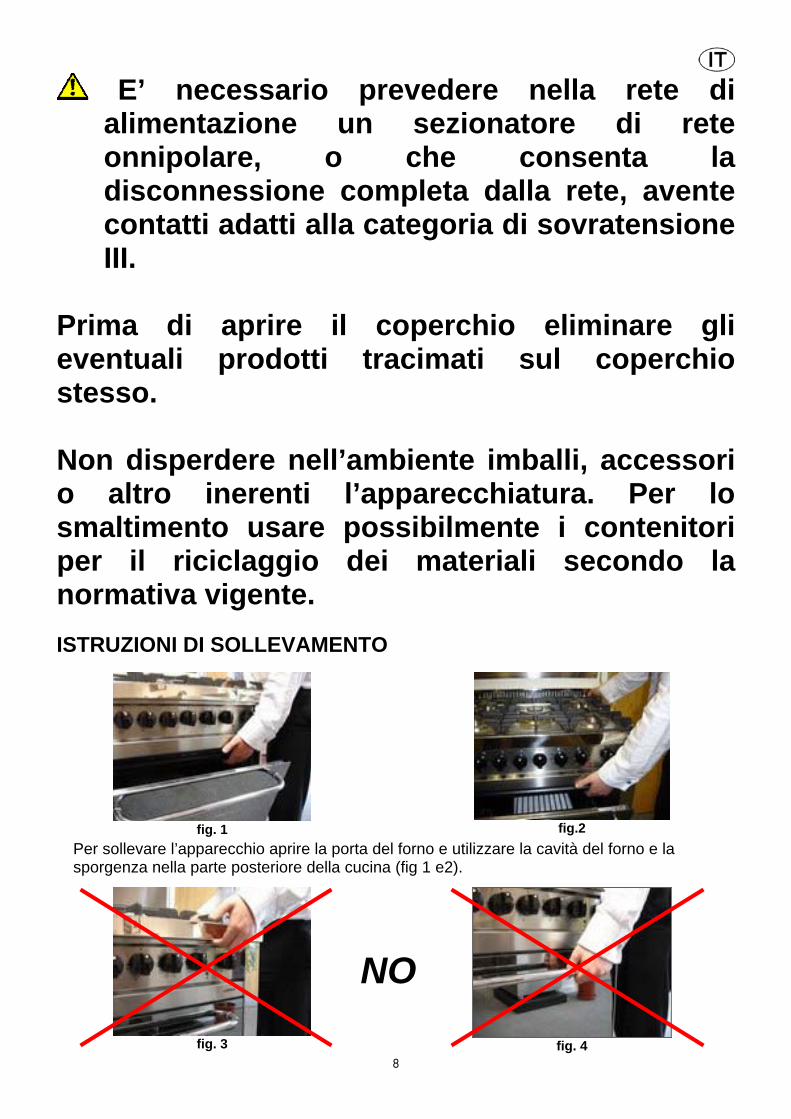
Prima di aprire il coperchio eliminare gli eventuali prodotti tracimati sul coperchio stesso. Non disperdere nell’ambiente imballi, accessori o altro inerenti l’apparecchiatura. Per lo smaltimento usare possibilmente i contenitori per il riciclaggio dei materiali secondo la normativa vigente. ISTRUZIONI DI SOLLEVAMENTO
fig. 1
fig.2
Per sollevare l’apparecchio aprire la porta del forno e utilizzare la cavità del forno e la sporgenza nella parte posteriore della cucina (fig 1 e2).
fig. 3
NO
fig. 4

9
NON sollevare la cucina utilizzando la sporgenza anteriore del piano cottura o la maniglia del forno (fig 3 e 4). Il sollevamento attraverso il piano cottura può causare lo sganciamento dei fissaggi di sicurezza ed il conseguente danneggiamento dei tubi gas dei bruciatori. Sollevare l’apparecchio attraverso la maniglia può causare lo scheggiatura o la rottura del vetro del forno. I danni conseguenti da queste errate operazioni non sono coperti da garanzia.
1. INSTALLAZIONE Tutte le operazioni di installazione, regolazione, trasformazione e manutenzione, devono essere eseguite da personale tecnico qualificato in accordo al presente manuale di servizio e secondo le normative vigenti. La ditta declina ogni responsabilità derivante da una cattiva regolazione, utilizzazione o una manomissione.
AVVERTENZE Prima dell’installazione assicurarsi che le condizioni di distribuzione locale del gas (natura e pressione) e l’alimentazione elettrica (voltaggio e amperaggio) siano corrispondenti a quelli indicati sulla targa posta sul bordo interno della fiancata sinistra dell’apparecchio. Questo apparecchio non è raccordato ad un dispositivo di evacuazione dei prodotti della combustione. Esso deve essere installato e raccordato conformemente alle norme in vigore. Fare particolare attenzione alle disposizioni applicabili in materia di ventilazione dei locali. Su ogni apparecchio viene indicato il tipo e la pressione del gas di predisposizione(vedi targhetta). 1.1 LOCALE DI INSTALLAZIONE DELLA CUCINA
Per garantire un buon funzionamento la cucina deve essere installata in un locale con volumetria minima di 26 m3, permanentemente ventilato dove possa affluire, in modo naturale, l’aria necessaria per la corretta combustione del gas,secondo le normative vigenti di installazione : UNI-CIG 7129-7131
L’afflusso naturale dell’aria deve avvenire per via diretta attraverso: Aperture permanenti (A), praticate su pareti del locale da ventilare che danno verso l’esterno; tali aperture devono avere una sezione minima di 100 cm2 per i modelli con dispositivo di sicurezza al piano di lavoro, realizzate in maniera tale da non poter essere ostruite né dall’interno né dall’esterno, posizionate ad una quota prossima al pavimento e comunque tali da non provocare disturbo al corretto funzionamento dei dispositivi di scarico della combustione. Condotti di ventilazione singoli oppure collettivi ramificati. L’aria di ventilazione dovrà essere prelevata direttamente dall’esterno in zona lontana da fonti di inquinamento. Se l’afflusso dell’aria non può avvenire direttamente dall’esterno, é consentita anche la ventilazione per via indiretta mediante prelievo dell’aria da locali attigui a quello da ventilare, purché non siano locali adibiti a camere da letto oppure con pericolo di

10
incendio, e comunque con le avvertenze e le limitazioni di cui alle norme vigenti applicabili: norme UNI-CIG 7129-7131. 1.2 SCARICO DEI PRODOTTI DELLA COMBUSTIONE Gli apparecchi di cottura devono sempre scaricare i prodotti della combustione in apposite cappe (C), che devono essere collegate a camini, canne fumarie, o direttamente all’esterno. In caso non esista la possibilità di applicazione della cappa, è consentito l’impiego di un elettroventilatore (E) installato su finestre o su parete in funzione contemporaneamente all’apparecchio, purché siano tassativamente rispettate le norme inerenti la ventilazione : norme UNI-CIG 7129-7131. 1.3 POSIZIONAMENTO DELLA CUCINA
a) Cucina inseribile tra i mobili (Building-In): tipo Y - classe 2 sottoclasse 2/1, (vedi figure )
La cucina di questa classe può essere inserita a diretto contatto dei mobili adiacenti, tranne nel caso di mobile con parete che supera l’altezza del piano di lavoro, in questo caso deve essere distanziato di almeno 5 cm per la parte superiore al piano di lavoro stesso. Se la cucina viene dotata di zoccolatura si devono prevedere, su detto particolare, aperture nella parte anteriore pari a 2 cm per la larghezza della cucina. I mobili devono essere costituiti da materiale che resista ad una temperatura di almeno 120°C. b) Cucina libera installazione (Free-Standing): tipo X - classe 1; vale come punto a) con l’eccezione che un fianco dell’apparecchio, deve essere lasciato libero per l’ispezione dell’eventuale tubo flessibile in gomma utilizzato per il
collegamento gas. Dopo aver tolto l’imballo, rimuovere il materiale plastico posto a protezione dei particolari in acciaio inox, alluminio e/o verniciati onde evitarne la fusione; si raccomanda di seguire questa operazione usando la massima cautela per evitare di rovinare le parti protette. Procedere a questo punto al montaggio dei piedini, devono essere fissati alle estremità delle feritoie del piedistallo della cucina. Possono essere regolati in altezza per allineare la cucina ad eventuali mobili esistenti, assicurarsi inoltre che sia perfettamente stabile. Sistemare i bruciatori, gli spartifiamma e le griglie nelle apposite sedi del piano di lavoro. Per non danneggiare il piano di lavoro in acciaio inox, inserire (solo sui modelli previsti) sulla griglia centrale poggiapentola, in tondino cromato, i gommini antigraffio in dotazione alla cucina.

11
Per l'installazione ancorare il fornello utilizzando il kit fornito riferendosi al disegno sottostante. Vengono fornite due staffe, che serviranno per ancorare la spalletta della cucina, seguendo le istruzioni dei disegni successivi. N.B. In caso di cucina senza spalletta si deve sollevarla leggermente per far entrare la staffa sull’orlo del piano.
N.B.: Durante il funzionamento dei bruciatori non devono esserci correnti d’aria, all’interno del locale, tali da disturbarne il buon funzionamento o addirittura causarne lo spegnimento.
ISTRUZIONI MONTAGGIO PIEDINI
Avvitando la rondella sul bullone del piedino assicurarsi che la slabbratura della rondella sia rivolta verso l’alto in direzione opposta alla cima della gamba.

12
Piedino assemblato con rondella in modo corretto. La parte bassa del piedino potrà essere svitata per regolare l’altezza e l’allineamento della cucina.
Sede per piedino sul fondo del forno. Per inserire i piedini nelle loro sedi appoggiare la cucina sul piano posteriore ed inserirli. NON fissare i piedini inclinando l’apparecchio, questo potrebbe danneggiarli.
Inserire la rondella precedentemente avvitata sulla cima del piedino nella base della cucina e farla scivolare lungo il canale.
Avvitare la parte alta del piedino finché la base del forno è bloccata tra la rondella ed il piedino stesso. Una volta che tutti quattro i piedini sono fissati sollevare la cucina avendo cura di distribuire il peso uniformemente su di essi. NON rovesciare l’apparecchio sulle gambe ma sollevarlo (questo richiederà due persone)
1.4 ALLACCIAMENTO ALLA RETE DI ALIMENTAZIONE DEL GAS:UNI-CIG 7129/7131 a) CLASSE 2 ( sottoclasse 2/1 cucina incassata tra i
mobili) : con tubo flessibile in acciaio inox a parete continua di cui alla norma in vigore: UNI-CIG 9891 con possibilità di allungamento massimo fino a 2000 mm; alle estremità, il tubo dovrà essere predisposto di raccordi, aventi filettatura secondo ISO 228/1 con apposita guarnizione di tenuta.

13
b) CLASSE 1 (cucina libera installazione): oltre a quanto riportato per la classe 2, anche con tubo flessibile non metallico conforme alla norma UNI-CIG 7140 , purchè nella messa in opera vengano rispettati i seguenti accorgimenti: che la lunghezza del tubo sia maggiore di 400 mm e minore di 1500 mm; che in nessun punto raggiunga temperature maggiori di 50° C; che non sia soggetto a sforzi di trazione e di torsione;che non presenti strozzature e sia facilmente ispezionabile lungo tutto il percorso;che non venga a contatto con parti taglienti, spigoli vivi o similari.
SOLO PER I MODELLI: XR96GV/C, XR96MF/C
Prima di procedere al collegamento del tubo flessibile non metallico bisogna fissare il portagomma e la relativa guarnizione, forniti a corredo , sul tubo/rampa posto sullo schienale della cucina . Per collegamento con: gas metano: il tubo dovrà avere il diametro interno di 13 mm, essere calzato al portagomma e quindi fissato con l’apposita fascetta: UNI-CIG 7141; gas liquido (GPL - bombola): il tubo dovrà avere il diametro interno di 8 mm, essere calzato al portagomma e quindi fissato con un’apposita fascetta : UNI-CIG 7141; sulla bombola dovrà essere installato un riduttore di pressione conforme alla normativa vigente: UNI-CIG 7432. Cucine con vano portabombola – queste cucine sono predisposte per utilizzare bombole di 10 Kg di GPL (dimensioni max. in mm Ø 270; h 600) e sono provviste di due attacchi per il collegamento del gas: uno all’interno del vano e uno nella parte posteriore sinistra; vengono prodotte con l’attacco del vano bombola chiuso con tappo e guarnizione mentre l’altra estremità è aperta.
Nel caso di utilizzo dell’attacco del vano bombola bisogna sostituire il tappo con il porta-gomma; utilizzare il tappo per chiudere l’attacco esterno. Fare attenzione di interporre sempre la guarnizione di tenuta. Il collegamento tra bombola e portagomma deve essere effettuato con tubo flessibile seguendo obbligatoriamente il percorso indicato nelle figure a lato e/o nella targhetta adesiva posta all’interno della porta vano bombola.

14
Dopo aver effettuato l’allacciamento accertarsi che non vi siano perdite di gas con strumentazioni appropriate oppure più semplicemente con acqua saponata.
1.5 ALLACCIAMENTO ALLA RETE ELETTRICA L’allacciamento della cucina alla rete elettrica di alimentazione viene effettuato mediante il cavo di cui è dotata la cucina o tramite cavo indicato a pag.28 ; è necessario prevedere nella rete di alimentazione un sezionatore di rete onnipolare, o che consenta la disconnessione completa dalla rete, avente contatti adatti alla categoria di sovratensione III. 1.6 TRASFORMAZIONE DEL GAS SUI BRUCIATORI DEL PIANO Bruciatori: ausiliari, semirapidi, tripla corona, pesciera. Questi bruciatori sono dotati di iniettori con forme tali da consentire un entrata di aria primaria calibrata per ogni tipo di gas; non necessita quindi di regolazione dell’aria. Per la trasformazione da un tipo di gas ad un altro procedere come segue:
togliere le griglie, i coperchietti,gli spartifiamma forati e i supporti bruciatori;
sostituire gli iniettori forati indicati in figura C secondo il tipo di gas impiegato consultando la Tabella 1 del manuale ;
rimettere al loro posto i supporti bruciatori, gli spartifiamma, i coperchietti e le griglie; regolare la portata del minimo seguendo le istruzioni elencate al paragrafo successivo.
1.7 REGOLAZIONE DEL MINIMO DEI BRUCIATORI DEL PIANO Rubinetti normali/valvolati Accendere i bruciatori nella posizione di massimo, togliere la manopola ed infilare un piccolo cacciavite a taglio all’interno nei fori posti sul cruscotto a lato del rubinetto (come da figura A). Allentare la vite del by-pass di 2 giri in senso antiorario e ruotare l’astina nella posizione di minimo. Regolare la vite precedentemente svitata fino a ottenere una fiamma ridotta ma stabile, anche a passaggi bruschi dalla posizione di massimo a quella di minimo con bruciatore freddo. Nel caso di rubinetti con sicurezza lasciare funzionare il bruciatore al minimo qualche minuto per accertarsi che il dispositivo non vada in blocco. In questo caso aumentare il minimo. N.B.: Per tarature a GPL la regolazione del minimo dei bruciatori deve essere effettuata avvitando a fondo i by-pass dei rubinetti. 1.8 TRASFORMAZIONE DEL GAS SUI BRUCIATORI FORNO E GRILL GAS Bruciatore forno. Per accedere all’iniettore del forno procedere come segue:
aprire la porta del forno e togliere la base del forno. svitare la vite che fissa il bruciatore all’interno del forno (sul forno gigante è fissata sulla
parete laterale della muffola) e sfilare il bruciatore dalla sua sede facendo la massima attenzione a non danneggiare la termocoppia fissata sullo stesso;
sostituire l’iniettore forato a seconda del tipo di gas impiegato consultando la tabella 1 del manuale.
15
rimettere il bruciatore nella posizione originaria. Regolazione del minimo del termostato del forno Per eseguire la regolazione del minimo agire nel modo seguente:
aprire la porta del forno. accendere il bruciatore nella posizione di massimo, chiudere la porta ed attendere circa
10 minuti (il tempo comunque necessario perché il forno si scaldi fino a circa 230° C ). sfilare la manopola del forno e, attraverso i fori posti sul cruscotto, a seconda del tipo di
termostato (fig. B), svitare di 2 giri la vite del by-pass del termostato stesso rimettere la manopola e ruotarla nella posizione di minimo, togliere la manopola e
regolare la vite precedentemente svitata fino a ottenere una fiamma ridotta e stabile anche a passaggi bruschi da massimo a minimo ed a rapide aperture/chiusure della porta.
N.B.: Per tarature a GPL la regolazione del minimo del bruciatore forno deve essere effettuata avvitando a fondo il by-pass del termostato. Bruciatore grill a gas. Per la trasformazione del gas su questo tipo di bruciatore vale quanto già scritto al paragrafo precedente “Bruciatore forno” con la sola variante che il bruciatore si trova nella parte superiore del forno, e non esiste la necessità della regolazione del minimo in quanto il bruciatore funziona sempre al massimo.
2. MANUTENZIONE
AVVERTENZE : Prima di eseguire qualsiasi operazione togliere la corrente elettrica e chiudere il gas a monte dell’apparecchiatura. Nel caso di sostituzione di componenti e/o accessori, utilizzare esclusivamente ricambi originali Lofra. Tutte le operazioni sottoindicate , devono essere eseguite da personale qualificato in accordo al presente manuale di servizio e secondo le normative vigenti: UNI-CIG 7129-7131.
2.1 TUBO DI GOMMA ALIMENTAZIONE DEL GAS ( UNI-CIG 7140) E’ necessario verificare periodicamente (1 volta all’anno) lo stato di conservazione del tubo di alimentazione del gas e di sostituirlo obbligatoriamente: entro la data di scadenza stampata sulla superficie esterna del tubo, nel caso presenti screpolature, tagli, abrasioni o bruciature, o venga a mancare la sua normale elasticità e risulti indurito ed eccessivamente plastico 2.2 CAVO DI ALIMENTAZIONE ELETTRICO Nel caso si rendesse necessaria la sostituzione del cavo di alimentazione elettrico, si fa presente che il tipo corretto da utilizzare per il collegamento alla rete elettrica è: H05VV-F 3x1.5 mm2 (diametro esterno max. 9mm), nel caso di correnti superiori a 16A il cavo deve avere sezione 2.5 mm2 . Lasciare il cavo sufficientemente lungo, per potere permettere una facile manutenzione; il cavo di terra (giallo-verde) una volta fissato ai terminali dell’impianto elettrico, dovrà risultare più lungo di almeno 2 cm rispetto agli altri 2 cavi (fase e neuto). Tale accorgimento permette di garantire la sicurezza elettrica, nel caso in cui accidentalmente venga strappato il cavo di alimentazione. Il cavo di alimentazione che presenta difetti, non deve essere riparato, ma va sostituito con un cavo equivalente a quello sopra

16
indicato. La sostituzione del cavo di alimentazione deve essere effettuata dall’assistenza tecnica autorizzata LOFRA o da personale tecnico specializzato. N.B. : Per le EMC requirement (IEC/EN 61000-3-3) la cucina (PD96MFRE/C) è condizionata all’allaccio della rete nel punto di interfaccia ad una impedenza minore o uguale di 0.36 ohm. Schema collegamento morsettiera con cavo già preinstallato
220-240 V ~ 2.3 SMONTAGGIO E MONTAGGIO DELLA PORTA DEL FORNO
Aprire totalmente la porta del forno, inserire il dispositivo blocca movimento di rotazione (A) sull’apposito gancetto delle staffe delle cerniere. Afferrare la porta ai lati e chiuderla lentamente finché si avverte una certa resistenza, a questo punto forzare e contemporaneamente alzare la porta verso l’alto in modo da liberare l’incastro della cerniera dal corpo della cucina e sfilarla. Per il montaggio eseguire al contrario le indicazioni sopra descritte facendo attenzione che l’incastro della cerniera sia inserito nella propria sede.
Per modelli CURVA inserire negli appositi fori un perno blocca movimento di rotazione. Afferrare la porta ai lati e chiuderla lentamente finché si avverte una certa resistenza, a questo punto forzare e contemporaneamente alzare la porta verso l’alto in modo da liberare l’incastro della cerniera dal corpo della cucina e sfilarla. Per il montaggio eseguire al contrario le indicazioni sopra descritte facendo attenzione che l’incastro della cerniera sia inserito nella propria sede. 2.4 SOSTITUZIONE DELLA LAMPADA Prima della sostituzione disinserire l’apparecchiatura della rete elettrica e se utilizzato precedentemente attendere che il forno si raffreddi. Per identificare la lampada consultare la targhetta dell’apparecchio. Aprire la porta del forno, svitare la calotta in vetro di protezione, sostituire la lampada (fare attenzione che deve essere del tipo incandescenza: 220-240V - T 300° C – E14 – 15/25 W o alogena: 12V – T 250°C – G4 – 5W | 220-240V – T 300°C – G9 – 40W ) e rimettere la protezione. N.B. In presenza di modelli con doppio forno con lampade diverse, nella targhetta dati posta sul lato sinistro aprendo la porta del forno, verrà indicato con FP la lampada da sostituire nel forno piccolo, mentre FG quella nel forno grande. 2.5 COPERCHIO IN CRISTALLO (solo per i modelli previsti) Per il montaggio del coperchio posizionare le cerniere nelle apposite sedi situate nella spalletta della cucina inserendole nelle feritoie esistenti (A), alzare il coperchio in verticale (B) e spingere verso il basso finché le cerniere non vanno in sede (C). Per lo smontaggio procedere all’inverso di quanto sopra descritto . A B C

17
3. USO DELLA CUCINA
AVVERTENZE: Nel caso di un spegnimento accidentale delle fiamme del bruciatore, chiudere la manopola di comando e non ritentare l’accensione se non dopo almeno 1 minuto. L’utilizzo di un apparecchio di cottura a gas produce calore e umidità nel locale in cui è installato. Vogliate assicurare una buona aerazione del locale mantenendo libere le aperture di ventilazione naturali o installando una cappa aspirante con condotto di scarico. Un utilizzo intensivo e prolungato dell’apparecchio può necessitare di un’aerazione supplementare per esempio l’apertura di una finestra o un’aerazione più efficace aumentando la potenza d’aspirazione meccanica se essa esiste. Sul frontalino comandi sono inseriti uno o due segnalatori luminosi, a seconda se il forno della cucina è funzionante a gas o elettrico. Nel caso di cucina con forno a gas un segnalatore verde si illumina ogni qualvolta viene inserito un elemento riscaldante (PIASTRE ELETTRICHE, GIRARROSTO, GRILL ELETTRICO). Nel caso di forno elettrico oltre al segnalatore verde c’è un indicatore giallo che si accende e si spegne per segnalare quando il TERMOSTATO interviene a regolare la temperatura all’interno del forno. 3.1 FUNZIONAMENTO DEL PIANO DI LAVORO Bruciatori a gas. Accensione elettronica integrata alla manopola: girare la manopola nella posizione di massimo premerla a fondo ed il bruciatore si accende automaticamente.
= Nessuna erogazione gas (rubinetto chiuso)
= Massima erogazione gas = Minima erogazione gas Per ottenere la portata minima ruotare la manopola in senso antiorario e posizionare l’indice della manopola stessa in corrispondenza della fiamma piccola . Dispositivo di sicurezza: una volta acceso il bruciatore tenere premuta la manopola per almeno 5 ÷ 10 secondi e quindi rilasciare, il bruciatore rimane acceso per effetto della termocoppia (A), che tiene aperto il passaggio del gas attraverso una valvola di sicurezza, la quale in caso di spegnimento accidentale del
bruciatore interrompe il passaggio del gas. Rendimento dei bruciatori: In corrispondenza dei bruciatori “medio e piccolo” si possono usare recipienti con diametro minimo di 100 mm. I recipienti non devono avere una base concava o convessa ma bensì piatta, per un rendimento ottimali dei bruciatori usare pentole come indicato in figura, cioè con diametro tale che le fiamme non fuoriescano dal fondo pentola. È consigliabile, non appena un liquido inizia a bollire, ridurre la fiamma quanto basta per mantenere l’ebollizione. Per motivi di sicurezza consigliamo l’utilizzo di pentole con i seguenti diametri da sovrapporre ai bruciatori: ausiliario, semirapido, rapido, tripla corona, pesciera.

18
Bruciatore Diametro minimo (cm) Diametro massimo cm) Piccolo (ausiliario) 10 14 Medio (semirapido) 15 20 Grande (rapido) 21 26 Tripla corona (ultra-rapido) dual Ø125mm AEO
24 26
Dual Ø145mm AEO e Quadrifoglio 26 30 N.B. A seconda della conformazione del piano tenere una distanza fra i bordi delle pentole di
minimo 10mm. Piastre elettriche
All’atto della prima inserzione o comunque se la piastra è rimasta inoperosa per molto tempo è necessario, al fine di eliminare l’eventuale umidità assorbita dall’impasto isolante, di provvedere al suo essiccamento inserendo la piastra per 30 minuti nella posizione n. 1 del commutatore. Per evitare dispersioni di calore e danni alle piastre, adoperare recipienti con fondo piatto e con diametro non inferiore o superiore, ma corrispondente a quello della piastra (fig. 14). Asciugare il fondo della pentola prima di posarlo sulla piastra. Non dimenticare la piastre accese senza pentola o con pentola vuota. Accensione delle piastre - centrare il recipiente sulla piastra e ruotare la manopola corrispondente fino a raggiungere la posizione desiderata (vedi Tabella 2), la numerazione crescente indica maggior potenza.
3.2 FUNZIONAMENTO DEL FORNO Forno a gas.
L’accensione del bruciatore del forno deve avvenire sempre con porta aperta. Tutti i forni sono dotati di termostato valvolato che, oltre a regolare la temperatura all’interno del forno, arresta il passaggio del gas in caso di accidentale spegnimento del bruciatore, evitando in tal modo fughe di gas incombusto. Per ottenere delle buone cotture si consiglia di preriscaldare il forno per 10÷15 minuti prima di introdurre il cibo. Conviene aprire la porta del forno lo stretto indispensabile, si evita così che la temperatura all’interno del forno stesso subisca brusche variazioni, pregiudicando l’esito delle cotture. Per le cucine gas ventilate accendere il ventilatore dopo 5 minuti di funzionamento del forno. Accensione integrata alla manopola - Aprire completamente la porta del forno, premere e
ruotare in senso antiorario, nella posizione di massimo, la manopola del
forno (simbolo ). Ad accensione avvenuta, mantenere la manopola premuta a fondo 5÷10 secondi circa quindi rilasciare. Il bruciatore rimane acceso per effetto del riscaldamento della termocoppia che tiene aperto il passaggio del gas attraverso la valvola di sicurezza. Dopo aver eseguito le suddette operazioni, chiudere la porta del forno e posizionare la manopola in corrispondenza della temperatura desiderata. Il dispositivo di accensione automatico (accensione elettronica e integrata
alla manopola) non deve essere azionato per un tempo superiore di 15 sec.; se dopo tale periodo il bruciatore non

19
è acceso, cessare di agire sul dispositivo ed attendere almeno 1 minuto prima di tentare una nuova accensione. Nel caso di mancanza momentanea di energia elettrica, è possibile accendere il bruciatore del forno manualmente. Aprire la porta del forno, girare la manopola ed indurre una fiamma attraverso l’apposita feritoia in figura. Nel caso di una estinzione accidentale della fiamma si consiglia di girare la manopola nella posizione di spegnimento aprire completamente FORNO ELETTRICO Forni statici Il calore per il riscaldamento del forno è prodotto dalle resistenze elettriche poste nella parte superiore (cielo) e parte inferiore (suola); tali resistenze possono funzionare sia in coppia che singolarmente. Questa situazione permette una cottura più omogenea, come ad esempio quando verso la fine della cottura il cibo può avere bisogno di più calore nella parte superiore o inferiore. La temperatura è sempre mantenuta costante dal termostato a seconda del valore selezionato e che va da 50° a 250° C. Aprire la porta del forno solo lo stretto indispensabile al momento della cottura. Durante questo tipo di cottura la perdita di umidità del cibo è lenta ed uniforme. Forni multifunzione Il calore per il riscaldamento si ottiene per mezzo della circolazione forzata di aria calda all’interno del forno. L’aria è riscaldata da una resistenza circolare adiacente alla ventola del motoventilatore forno, e la sua circolazione avviene grazie alla ventola stessa che la distribuisce in modo uniforme e veloce. Infatti con questo tipo di forno la cottura è più veloce rispetto a quella tradizionale e con temperature inferiori di 10-20° C. Anche in questo caso il termostato garantisce la temperatura costante preselezionata all’interno del forno e che va da 50° a 250° C. Per qualsiasi tipo di cottura è consigliabile il preriscaldamento del forno. È ideale per scongelamenti e per la cottura contemporanea di più pietanze lasciandone inalterati i sapori. Accensione delle resistenze del forno multifunzione: ruotare la manopola (T) ed impostare la temperatura selezionare con la manopola (F) una modalità di cottura.
Forno Misto (gas/elettrico) Determinati modelli di cucine hanno la possibilità di avere il forno funzionante sia a gas che elettrico. Per l’accensione avvalersi di quanto descritto nei punti precedenti “forno gas” e “forno elettrico”. Per motivi di sicurezza il funzionamento deve avvenire separatamente.
Non usare materiali ruvidi abrasivi o raschietti metallici affilati per pulire le porte di vetro del forno dato che possono graffiare la superficie e causare la frantumazione del vetro.
3.3 FUNZIONAMENTO DEL GRILL
Per motivi di sicurezza non funziona contemporaneamente il grill elettrico con il forno a gas.

20
Le vivande da cuocere vanno appoggiate sulla griglia del forno e questa, a sua volta, deve essere posizionata all’interno del forno stesso a seconda del tipo di cibo, come ad esempio: le carni piatte e sottili vanno poste sul gradino più vicino al grill, mentre arrosto arrotolato, pollame ecc. sul gradino centrale, la leccarda raccogli sugo va inserita nelle guide sottostanti alla griglia. Funzionamento del grill a gas : Si consiglia di usare il grill a gas come completamento della cottura al forno quindi al massimo 15-20 minuti o per cottura con girarrosto . Tutti i grill a gas sono dotati di sistema di sicurezza che in caso di accidentale spegnimento del bruciatore arresta automaticamente il passaggio del gas. Il funzionamento avviene con uno speciale termostato a due vie , che a seconda di come viene ruotata la manopola riesce a far funzionare o il bruciatore del forno o il bruciatore del grill . Il bruciatore del grill non ha alcuna regolazione bensì funziona sempre alla portata massima . L’accensione può avvenire sia manualmente che elettronicamente ; a questo proposito avvalersi delle indicazioni precedentemente fornite. Funzionamento del forno elettrico :
a) MODELLI CON FORNO ELETTRICO, l’accensione avviene ruotando la manopola del forno verso destra (in senso orario) finché l’indice si posiziona sul simbolo del grill
(ultima posizione della manopola).
b) MODELLI CON FORNO MULTIFUNZIONE, funzionamento del grill: ruotare la manopola delle funzioni verso destra (F) nella posizione di cottura al grill desiderata, quindi agire sulla manopola del termostato (T) e impostare la temperatura di 200° C. La porta del forno deve rimanere chiusa (non è previsto l’uso del paracalore manopole).
d) MODELLI CON FORNO MULTIFUNZIONE E GRILL
RADIANTE, la cottura al grill avviene per irraggiamento e il calore è prodotto da una particolare resistenza che raggiunge in pochi secondi alte temperature, producendo così raggi infrarossi i quali, attraverso un “vetroceramico” trasparente, consente rapide cotture. La disposizione del filamento della resistenza e l’elevato grado di isolamento consentono inoltre una distribuzione del calore concentrata solo sulla superficie del vetroceramico con conseguenti cotture più uniformi e risparmio di energia. Si raccomanda di effettuare la pulizia dopo che il forno si è raffreddato. Il vetroceramico permette una maggiore e facile pulizia in più protegge l’elemento riscaldante da schizzi e grasso.
e) MODELLI CON GRILL VARIABILE Funzionamento del grill: ruotare la manopola delle funzioni verso destra (F) nella posizione di cottura al grill desiderata, quindi agire sulla manopola del termostato (T),
impostare la temperatura di 200° C e regolare la manopola del grill variabile nella posizione di MIN – MED – MAX a seconda dell’utilizzo.
La porta del forno deve rimanere chiusa (non è previsto l’uso del paracalore manopole).
ATTENZIONE: in caso di rottura del vetroceramico scollegare l’alimentazione elettrica e chiamare il Centro di Assistenza Lofra Autorizzato.
Se la superficie del grill è rotta, spegnere l’interruttore dove è collegata l’apparecchiatura dall’impianto elettrico per evitare il rischio di shock elettrici.

21
ATTENZIONE: le parti accessibili possono diventare molto calde durante l’uso. I bambini dovrebbero essere tenuti a distanza.
3.4 GIRARROSTO (solo per i modelli dotati) Il girarrosto serve per cucinare arrosti allo spiedo mediante il forno e il grill. Dopo aver disposto il vassoio del forno (leccarda raccogli grassi) sul ripiano più basso si devono effettuare le seguenti operazioni - montare sullo schidione l’apposita manopola, infilare su di esso il cibo da cuocere fissando alle estremità con le due forchette mobili (per evitare che il motore del girarrosto sforzi inutilmente, cercare di distribuire il peso su tutto lo schidione). - Inserire l’asta spiedo nell’apposito supporto e quindi l’albero motore. - Svitare la manopola dello spiedo ed avviare il motore con l’interruttore posto sul frontalino comandi ed inserire il grill. 3.5 CONTAMINUTI Si tratta di contaminuti meccanico con possibilità di funzionamento da 0 a 60 minuti e con avvisatore sonoro al termine del tempo preselezionato. Per metterlo in funzione bisogna ruotare la manopola verso destra e far coincidere l’indice con il tempo desiderato; la manopola ritorna automaticamente nella posizione di zero e, allo scadere del tempo selezionato, si inserisce il segnale acustico. 3.6 CUCINE MULTIFUNZIONE
Le cucine multifunzione sono caratterizzate dal fatto che il calore, nel forno, può propagarsi sia in modo naturale (convezione), che forzato (motoventilatore). Grazie a questa particolarità si possono ottenere, agendo sulla manopola funzioni (F), n. 8 diverse possibilità di cottura con regolazione separata della temperatura con manopola termostato (T) da 50° a 250° C; si possono soddisfare così le esigenze di cottura più disparate. A seconda dei modelli , le cucine sono equipaggiate con temporizzatore di fine cottura o
con programmatore elettronico digitale. Cucine con temporizzatore di fine cottura meccanico. Le cucine predisposte con questo dispositivo permettono sia il funzionamento ininterrotto manuale che la programmazione del tempo di cottura del forno da 0 a 120 minuti. Funzionamento ininterrotto manuale: impostare il tipo di cottura e la temperatura del forno tramite le rispettive manopole “A” e “B”, ruotare la manopola del temporizzatore “C” in senso antiorario e far
coincidere l’indice con il simbolo . Funzionamento programmato: impostare il tipo di cottura e la temperatura del forno tramite le rispettive manopole “A” e “B”, ruotare la manopola del temporizzatore “C” in senso orario e posizionarla in corrispondenza del tempo di cottura desiderato. Allo scadere del tempo programmato il forno si spegnerà automaticamente.
Attenzione: la manopola non deve essere ruotata in senso antiorario oltre il simbolo della mano , altrimenti si causerà la rottura del temporizzatore.
22
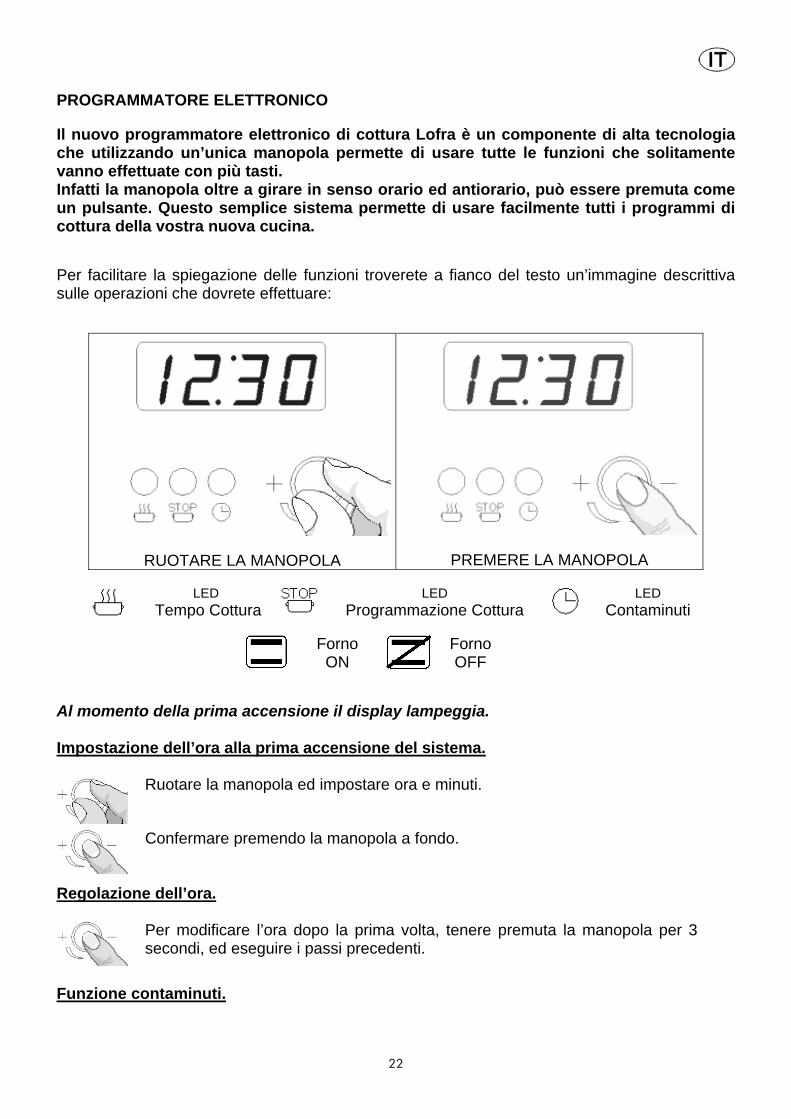
PROGRAMMATORE ELETTRONICO Il nuovo programmatore elettronico di cottura Lofra è un componente di alta tecnologia che utilizzando un’unica manopola permette di usare tutte le funzioni che solitamente vanno effettuate con più tasti. Infatti la manopola oltre a girare in senso orario ed antiorario, può essere premuta come un pulsante. Questo semplice sistema permette di usare facilmente tutti i programmi di cottura della vostra nuova cucina. Per facilitare la spiegazione delle funzioni troverete a fianco del testo un’immagine descrittiva sulle operazioni che dovrete effettuare:
RUOTARE LA MANOPOLA
PREMERE LA MANOPOLA
LED
Tempo Cottura LED
Programmazione Cottura LED
Contaminuti
Forno ON
Forno OFF
Al momento della prima accensione il display lampeggia. Impostazione dell’ora alla prima accensione del sistema.
Ruotare la manopola ed impostare ora e minuti.
Confermare premendo la manopola a fondo.
Regolazione dell’ora.
Per modificare l’ora dopo la prima volta, tenere premuta la manopola per 3 secondi, ed eseguire i passi precedenti.
Funzione contaminuti.

23
Girare la manopola per impostare i tempi del "contaminuti".
Il display mostra il tempo residuo ed il led lampeggia, al termine compare “END” e viene attivato un avvertimento sonoro.
Il segnale sonoro viene ripetuto per 10 minuti. E’ intermittente nei primi 30 secondi, successivamente un avvertimento ogni 15 secondi. Per interrompere premere la manopola.
Girando la manopola in senso orario si riattiva un nuovo conteggio e si ha la possibilità di modificare il tempo. Per interrompere la funzione girare la manopola fino a 0 o premere la manopola.
Funzione tempo cottura.
Girando la manopola con forno acceso si attiva la funzione "tempo cottura",
il led lampeggia e viene mostrato il tempo residuo. Quando sul display compare “END” si spegne il forno e si attiva un avvertimento sonoro.
Per tornare all'ora premere la manopola o mettere in posizione off la manopola del forno.
Per inserire una funzione “contaminuti” durante la cottura con forno acceso e “tempo cottura” non inserito, per essere avvisati senza che il forno si spenga, e' sufficiente premere 2 volte la manopola, la funzione contaminuti si attiva con un tempo preimpostato di 5 minuti,
E’ possibile modificare il tempo agendo sulla manopola.
Funzione programmazione cottura con partenza ritardata.
Premendo la manopola con forno spento si attiva “programmazione cottura”,
si accende il led lampeggiante , si imposta con la manopola l'ora di accensione automatica e si conferma premendo.
Ruotare la manopola per impostare il tempo di cottura, i due led lampeggiano.
Premere la manopola, per ritornare all’ora, la programmazione e' finita.
Lampeggia il led di programmazione ad indicare la funzione attiva. Successivamente impostare funzione e temperatura desiderata del forno agendo sulle manopole opportune. All'ora impostata, il forno si accende, il display inizia a visualizzare il residuo
tempo di cottura e lampeggia il led Alla fine si spegne e viene visualizzato "End", seguito da segnali sonori.

24
Attenzione: la funzione non si attiva se si tenta di impostare un tempo di cottura
nullo o l'ora di partenza pari all'ora attuale. L'impostazione va fatta entro 1 minuto, altrimenti la funzione termina. Se acceso, il forno viene disattivato alla fine della configurazione.
Se si vuole continuare la cottura, ruotare la manopola, per impostare il nuovo tempo.
N.B. Con una impostazione di partenza programmata, la funzione resta memorizzata, anche se viene a mancare l’energia elettrica. Il forno si accenderà con un ritardo pari al tempo per cui e' mancata l’energia elettrica.
PROGRAMMATORE ELETTRONICO per cucine con “forno gas ventilato”
RUOTARE LA MANOPOLA
PREMERE LA MANOPOLA
LED Tempo Cottura
Impostazione dell’ora alla prima accensione del sistema.
Ruotare la manopola ed impostare ora e minuti.
Confermare premendo la manopola a fondo.
Regolazione dell’ora.
Per modificare l’ora dopo la prima volta, tenere premuta la manopola per 3 secondi, ed eseguire i passi precedenti.

25
Funzione tempo cottura.
Girando la manopola con forno acceso si attiva la funzione "tempo cottura",
il led lampeggia e viene mostrato il tempo residuo. Quando sul display compare “END” si spegne il forno e si attiva un avvertimento sonoro.
Per tornare all'ora premere la manopola o mettere in posizione off la manopola del forno. Girando la manopola a destra si riattiva un nuovo conteggio; se il forno è acceso è possibile impostare un nuovo tempo tempo cottura .
Per interrompere la funzione girare la manopola fino a 0 o premere la manopola
N.B. Se la manopola viene premuta per due volte consecutive è possibile impostare il timer per intervalli di 5 minuti. Premere in successione per raggiungere il tempo desiderato.
Attenzione: non lasciare mai all’interno del forno a riposo, cose diverse da pentolame adatto alla cotture da forno.
PROGRAMMATORE ELETTRONICO PER CUCINE SERIE "RUSTICA''
PROGRAMMATORE DI COTTURA REGOLAZIONE DELL'ORARIO Per regolare l’ora indicata dalle lancette dell'orologio premere per 4 volte la manopola fino a far lampeggiare l’icona "OROLOGIO". Quindi per aumentare o diminuire I'orario visualizzato ruotare la manopola in senso orario o antiorario, la lancetta dei minuti si muoverà ad intervalli di 1 minuto. Trascorsi 10 secondi dall'ultima regolazione il timer uscirà automaticamente dalla modalità. COTTURA MANUALE A riposo il timer consente la cottura manuale agendo sull'interruttore generale del forno (esterno al dispositivo).

26
PROGRAMMAZIONE DELL'ORA DI FINE COTTURA La programmazione dell'ora di fine cottura permette di iniziare subito e terminare la cottura in maniera automatica in base all'ora programmata. Per programmare l'ora di fine cottura premere 2 volte velocemente la manopola fino ad ottenere il lampeggio dell' icona “STOP”. Per aumentare o diminuire il tempo di cottura, ruotare manopola in senso orario o antiorario, la lancetta dei minuti si muoverà ad intervalli di 1 minuto. Il lampeggio dell'icona "STOP" continuerà per 10 secondi dall'ultima impostazione per poi tornare alla visualizzazione dell’ora se non confermerete il programma. Per confermare bisogna premere la manopola purché siano stati programmati almeno 2 minuti di cottura. Successivamente la cottura verrà avviata. Per visualizzare il programma impostato premere velocemente la manopola. Al termine della cottura I'icona "STOP" lampeggerà e I'allarme emetterà segnali acustici. Dopo 1 minuto l'allarme verrà disabilitato e l'icona "STOP" rimarrà lampeggiante fino alla pressione della manopola. Per annullare il programma prima del termine, premere la manopola per 3 secondi: il programma sarà annullato e il timer ritornerà in modalità cottura manuale. PROGRAMMAZIONE DELL'ORA DI INIZIO COTTURA E FINE COTTURA La programmazione dell'ora di inizio cottura permette di iniziare e terminare la cottura in maniera automatica in base alle ore programmate. Per programmare l'ora di inizio cottura premere una volta velocemente la manopola fino ad ottenere il lampeggio dell' icona "START". Per incrementare o decrementare l'ora di inizio cottura a passi di 1 minuto, ruotare manopola in senso orario o antiorario. Il lampeggio dell'icona "START" continua per 10 secondi dall'ultima regolazione. Se entro questo tempo non si ruota o preme la manopola le lancette ritornano automaticamente a visualizzare l'orario ed il programma verrà annullato. Se si preme la manopola l'ora di Inizio Cottura viene memorizzata (icona "START" accesa fissa), purché sia stato programmato almeno 1 minuto successivo, e si passa all'impostazione dell'ora di Fine Cottura (l'icona "STOP" diventa lampeggiante) Per la programmazione dell'ora di Fine Cottura si segua la procedura precedentemente descritta. Per segnalare l’avvenuta programmazione rimarranno accese le due spie “START” e “STOP”. PROGRAMMAZIONE DEL CONTAMINUTI La programmazione del contaminuti permette di avere un semplice allarme al termine di un tempo programmato senza attivare la cottura. Per programmare un "allarme" premere velocemente la manopola 3 volte fino ad ottenere il lampeggio dell' icona "TIMER". Quindi ruotare la manopola, l'impostazione del contaminuti è identica a quella dell'ora di Fine Cottura (vedere il paragrafo relativo) Il contaminuti è utilizzabile solo quando non c'è nessun programma in corso. VISUALIZZAZIONE DEL PROGRAMMA IMPOSTATO Per visualizzare il programma impostato premere velocemente la manopola, nello stesso istante il programmatore visualizzerà il programma spostando le lancette sui tempi inseriti ed evidenziando le fasi con il lampeggio delle icone relative.

27
Il programmatore ritorna poi automaticamente a visualizzare I'ora attuale e continua con l'esecuzione del programma impostato. CANCELLAZIONE DEL PROGRAMMA IMPOSTATO Per cancellare il programma impostato premere per qualche secondo la manopola fino allo spegnimento delle icone relative e la segnalazione sonora di un secondo beep. Il programmatore ritorna poi automaticamente al modo cottura manuale. SEGNALAZIONE BLACKOUT Il timer non annulla il programma in caso di blackout. Il timer segnala ogni mancanza di alimentazione di rete tramite il lampeggio del simbolo "OROLOGIO", per permettere all'utilizzatore di verificare che I'ora sia corretta. In questo caso, per disabilitare la segnalazione premere velocemente la manopola. ELENCO FUNZIONI (solo per i modelli multifunzione)
1 Luce forno
2 Cottura tradizionale. Il calore si propaga uniformemente sia dall’alto che dal basso. Ideale per la cottura dei biscotti e della pasticceria. Consigliata per cotture singole.
3 Cottura dal basso. II calore si diffonde unicamente dal basso per dare un tocco finale ad una cottura già avvenuta.
4 Cottura dall’alto. Il calore proviene dalla resistenza del cielo. Ideale per cuocere la parte superiore dei cibi senza grigliare.
5 Cottura al grill e girarrosto(*). Il calore si espande per irraggiamento. Ideale per cucinare al grill, per rosolare, dorare, gratinare.
6 Cottura maxi-grill e girarrosto (*). Vale lo stesso della funzione 5 però con potenza più elevata e maggiore superficie di irraggiamento.
7 Cottura maxi-grill con forno ventilato e girarrosto(*). Il calore si espande per irraggiamento e contemporaneamente la ventola lo diffonde in modo uniforme. Ideale per rosolare i cibi senza asciugarli internamente.
8 Cottura uniforme.
Il calore emesso dalle resistenze inferiore e superiore viene diffuso dalla ventola che permette una cottura uniforme interna/esterna in tempi estremamente ridotti. Consigliata per cotture singole.
9 Cottura con forno ventilato.
Il calore si propaga per ventilazione forzata. Ideale per i cibi che richiedono un alto grado

28
di cottura all’esterno e minore all’interno. Un sistema di cottura che consente di cucinare contemporaneamente tre piatti diversi Scongelamento super ventilato. Posizionando il selettore in “Cottura con forno ventilato” ed il termostato in posizione 50°, è possibile ottenere uno scongelamento dei cibi in tempi estremamente contenuti.
10 Scongelamento dei cibi.
Lo scongelamento si ottiene ventilando l’interno del forno (Termostato in posizione “0”) (*) SOLO PER MODELLI DOTATI
FUNZIONI CUCINE (solo i modelli …SMF)
1 Luce forno
2 Cottura tradizionale. Il calore si propaga uniformemente sia dall’alto che dal basso. Ideale per la cottura dei biscotti e della pasticceria. Consigliata per cotture singole.
3 Cottura uniforme. Il calore emesso dalle resistenze inferiore e superiore viene diffuso dalla ventola che permette una cottura uniforme interna/esterna in tempi estremamente ridotti. Consigliata per cotture singole.
4 Cottura al grill. Il calore si espande per irraggiamento. Ideale per cucinare al grill, per rosolare, dorare, gratinare.
5 Cottura al grill con forno ventilato.
Il calore si espande per irraggiamento e contemporaneamente la ventola lo diffonde in modo uniforme. Ideale per cucinare al grill rosolare, dorare, gratinare i cibi senza asciugarli internamente.
6 Cottura dal basso. II calore si diffonde unicamente dal basso per dare un tocco finale ad una cottura già avvenuta.
CUCINA UP&DOWN (2 FORNI SOVRAPPOSTI)
MODELLI CON FORNO E GRILL A GAS GRILL
Per ottenere migliori risultati è necessario pre-riscaldare il grill per almeno 3 minuti a porta aperta. In caso di spegnimento accidentale della fiamma, riportate la manopola su “off” ed evitate di accendere il forno prima che sia trascorso almeno un minuto.
FORNO In caso di funzionamento simultaneo dei forni, si consiglia di accendere prima il
forno UP e dopo almeno 3 minuti il forno DOWN. Per un uso ottimale vi raccomandiamo di pre-riscaldare il forno per almeno 15 minuti posizionando la temperatura a seconda della pietanza da cuocere. Non posizionare mai piatti direttamente sopra il bruciatore del forno! Non ricoprire l’interno del forno con carta d’alluminio.

29
In caso di spegnimento accidentale della fiamma, riportare la manopola su “off” e evitate si accendere il forno prima che sia trascorso almeno un minuto.
MODELLI CON FORNO ELETTRICO/MULTIFUNZIONE
Funzionamento:
• FORNO INFERIORE
(v. punto 3.6)
• FORNO SUPERIORE
Cottura tradizionale con propagazione del calore sia dall’alto che dal basso. Con la stessa manopola si può impostare la temperatura fino ad un massimo di 250°.
Cottura dal basso con temperatura massima fino a 250°C ; posizione consigliata per cotture con salse liquide e/o fondi di cottura liquidi
Cottura dall’alto con temperatura massima fissa a 250°; posizione consigliata per cotture soffici di gratinatura e grigliatura (pane tostato).
Cottura dall’alto con temperatura massima fissa a 250°; posizione consigliata per grigliare in modo veloce (carni rosse) o per gratinare piatti veloci.
CUCINA CON DIMENSIONI 96 E 126 A 3 FORNI ELETTRICI
90x60 120x60
Le cucine dimensioni 90x60 a tre forni hanno a disposizione 1 forno da 60 litri e 2 forni da 30 litri con resistenze elettriche. Le cucine con dimensioni 120x60 a tre forni hanno a disposizione 2 forni da 60 litri e 1 da 30 litri

30
MODELLI
Resistenza suola
Resistenza cielo
Resistenza grill
Resistenza Maxi- grill
Resistenza circol.
Forno down 60l 3 forni dimensione 90 Forno up 30l Forno right 30 l
1650 W
1200 W
1200 W
900 W
500 W
500 W
1500 W
1000 W
1000 W
2100 W
2000 W
Forno down 60l 3 forni dimensione 120 Forno up 30l Forno right 60 l
1650 W
1200 W
1650 W
900 W
500 W
900 W
1500 W
1000 W
1500 W
2100 W
2100 W
2000 W
2000 W
3.7 PIANO DI COTTURA CON GLASS-PLATE (solo per i modelli previsti) Il GLASS-PLATE è un sistema innovativo di cottura: abbinando il calore prodotto da una particolare resistenza ad alta resa con un “vetroceramico” che permette il passaggio dei raggi infrarossi, consente rapide cotture dirette, tipo alla piastra, oppure particolari cotture in pentola o come scaldavivande. La superficie del vetroceramico è divisa in due parti con possibilità di funzionamento singolo o combinato, le due zone radianti sono indicate con un rettangolo serigrafato e sono alimentate da speciali resistenze comandate da un Modulo Elettronico sensibile al tatto (touch-control). Caratteristiche del GLASS-PLATE Velocità di cottura e distribuzione termica - n°2 elementi riscaldanti separati il cui filamento arriva in pochi secondi ad alta temperatura generando raggi infrarossi. L’elevato spessore di isolamento in fibra di vetro che evita la dispersione di calore con conseguente risparmio di energia e la particolare disposizione del filamento, consentono una distribuzione termica rapida e omogenea su tutto il vetro. Superficie vetroceramico - è un materiale atossico di facile e veloce pulizia che può raggiungere elevate temperature e consente la cottura combinata per infrarosso (tipo alla griglia) e per contatto (tipo alla piastra). Modulo Elettronico - il “touch-control” permette una facile e precisa regolazione. Cotture - ideale per grigliare direttamente sul vetro salsicce, hamburger, carne, pesce, verdure, crepes, pizza, ecc.; con questo sistema la qualità della cottura risulta ottima e salutare perché il gusto del cibo rimane inalterato in quanto il vetro non assorbe i sapori, non ci sono residui carboniosi, non c’è uso di grassi. Ottimo anche nel caso di cotture in pentola lente o delicate (temperature basse e uniformi) oppure come scaldavivande. Pulizia e consigli Si raccomanda di effettuare la pulizia quando il vetro si è raffreddato. Lavare il vetro con il tipo di liquido detergente di cui si fornisce un campione oppure con acqua saponata, per lo sporco più resistente usare l’apposito raschietto fornito a corredo.
Non usare mai materiale abrasivo come paglietta scotch bryte, spugnette metalliche o altro. Per la cottura in pentola si consiglia l’uso di contenitori con fondo piatto e liscio, fare attenzione che pentole in ghisa o con fondo ruvido possono lasciare tracce chiare che possono essere tolte con un panno imbevuto di aceto.
Terminata la cottura, la zona riscaldata rimane calda per un certo tempo, fare molta attenzione a non appoggiarvi le mani. Tenere lontano i bambini.
Avvertenze - non utilizzare i guanti - utilizzare con dita pulite Utilizzo

31
Normalmente il piano si presenta in funzione “lock” con pallino rosso sopra al simbolo cioè la funzione di sicurezza che inibisce la selezione di tutti i sensori. Per sbloccare il modulo, selezionare il simbolo fino a quando scompare il pallino rosso. Se non vengono selezionati i sensori, dopo che è stato sbloccato, in automatico dopo 30 secondi il modulo si porta in “lock”, cioè pallino rosso sul simbolo Per accendere bisogna che il modulo sia sbloccato, quindi premere il simbolo on/off , a questo punto si visualizzano entrambi display numerici, quello di SX comanda la piastra anteriore, quello di DX comanda la piastra posteriore. Dal momento che si visualizzano i display numerici si hanno 10 sec. per decidere, altrimenti il modulo si spegne. Quando i display numerici sono accesi, indicando “0” possiamo agire selezionando i simboli “+/-” per aumentare o diminuire la potenza della piastra, il numero “9” indica la potenza massima, il numero “1” indica una potenza minima. Calore residuo Una volta spenta la piastra comparirà la lettera “H” di colore residuo fino a quando la piastra sarà calda (fino a quando la superficie del vetro ha una temperatura > 65°C) Funzione di riscaldamento Questa funzione imposta la massima potenza per un tempo definito. La funzione di riscaldamento si attiva selezionando il livello “9” e selezionando il simbolo “+”, a questo momento il punto decimale del display lampeggia (per 10 sec., dopodiché si annulla), durante questi 10 sec. deve essere selezionato il livello di potenza tra “1” e “8”, una volta selezionato e trascorso il tempo il punto decimale rimarrà fisso e verrà emesso un segnale acustico ad indicare che la piastra è in funzione. Se livello di potenza selezionato è “0” o “9” la funzione di riscaldamento viene annullata. Se la funzione di riscaldamento è attiva, premendo il simbolo “+” la durata della funzione riscaldamento sarà la durata per il nuovo livello di potenza. Se il nuovo livello è “9” la funzione sarà annullata. Tempi di riscaldamento
Livelli di potenza Tempo
1 1’12” 2 2’44” 3 4’48” 4 5’28” 5 6’30” 6 1’12” 7 2’44” 8 2’44”

32
La funzione di riscaldamento può essere annullata premendo il simbolo “-“ Blocco a chiave La funzione di blocco chiave può essere attivata quando le piastre sono accese o quando sono spente. Se le piastre sono accese, la funzione blocco chiave blocca tutti i sensori ad eccezione dell'interruttore generale di accensione/spegnimento e il blocco tastiera. Quando le piastre sono spente la funzione blocco tasti blocca tutti i sensori, compreso il generale On/Off tranne la funzione blocco a chiave . Funzionamento del timer Il timer può funzionare come contaminuti o può funzionare come temporizzatore per lo spegnimento delle piastre. La funzione contaminuti: si ottiene selezionando prima la piastra ed il suo livello di potenza, poi si seleziona il simbolo “+” e compaiono “00” a questo punto con il simbolo del tempo “+” si seleziona il tempo e comincia il conto alla rovescia. Al termine del tempo selezionato il modulo emette un segnale acustico. Il tempo può essere annullato premendo i simboli “+” e “-“ contemporaneamente. Temporizzare lo spegnimento delle piastre: si ottiene sezionando il simbolo del timer “+” a questo punto compare nel display “00” e le lettere “t” nei display delle piastre, selezionare la piastra desiderata (la funzione agisce solo su una piastra per volta), impostare la potenza con il simbolo delle piastre “+” in questo istante compare un pallino in corrispondenza del simbolo vicino al display della piastra selezionata, impostare poi il tempo desiderato con i simboli del timer “+ o –“ al termine del tempo ci sarà lo spegnimento della piastra ed un segnale acustico che durerà per un minuto. Il timer mostrerà “00” lampeggiante, questo potrà essere cancellato sfiorando qualsiasi sensore. Spegnimento automatico Il tempo massimo cui una piastra può stare accesa dipende dalla potenza scelta: Livelli di potenza max tempo(ore)
Livelli di potenza
Max.
tempo (ore)
1 10 2 5 3 5 4 4 5 6 6 2 7 2 8 2 9 1
Quando viene spento il glass-plate se rimane sopra una pentola calda, il piano impiega più tempo a raffreddarsi.
33
In caso di interruzione della corrente elettrica durante il funzionamento, una volta tornata la tensione i led potrebbero lampeggiare ad indicare che le piastre sono calde oppure che devono essere nuovamente impostate.
ATTENZIONE: in caso di rottura del vetroceramico interrompere l’alimentazione elettrica e chiamare il Centro di Assistenza Lofra Autorizzato.
3.8 PIANO DI COTTURA IN VETROCERAMICA TOTAL-GLASS (solo per i modelli previsti)
Tutte le operazioni di installazione, regolazione, trasformazione e manutenzione, devono essere eseguite da personale tecnico qualificato secondo le normative e prescrizioni in vigore. La ditta declina ogni responsabilità derivante da una cattiva installazione, regolazione, manomissione, utilizzazione dell’apparecchiatura.
ATTENZIONE:
Se la superficie è incrinata cioè con fessure, spegnere l’apparecchio per evitare la possibilità di scosse elettriche.
- Queste istruzioni riguardano le cucine totalmente elettriche e con piano vetroceramico ed integrano il nostro Manuale di Servizio cui si quindi deve fare riferimento . - Prima di procedere all’installazione controllare i dati di targa per verificare che l’impianto
domestico possa sopportare il carico dell’apparecchiatura. - Le condizioni di questo apparecchio sono scritte sulla targa posta sul bordo interno della
fiancata sinistra. - L’apparecchiatura è predisposta per il funzionamento a 230V; per allacciamenti diversi
consultare la targa posizionata nella parte posteriore, accanto alla morsettiera, contenente gli schemi per il collegamento elettrico.
- La cucina non è corredata di cavo di alimentazione, si raccomanda di usare un cavo del tipo H05RR-F, per la sezione consultare lo specchietto riassuntivo sotto riportato.
- Se l’apparecchio non è provvisto di cavo di alimentazione e spina, è necessario prevedere nella rete di alimentazione un dispositivo che assicuri la disconnessione dalla rete, con una distanza di apertura dei contatti che consenta la disconnessione completa nelle condizioni della categoria di sovratensione III (4000V), conformemente alle regole di installazione.
- La cucina deve essere collegata ad un efficiente impianto di terra. Nel collegamento alla morsettiera il cavo di terra deve essere più lungo di almeno 1 cm rispetto ai cavi di alimentazione.
- Il cavo di alimentazione deve essere posizionato in maniera tale che non superi la temperatura di 50° C oltre a quella dell’ambiente.
PIANO VETROCERAMICO
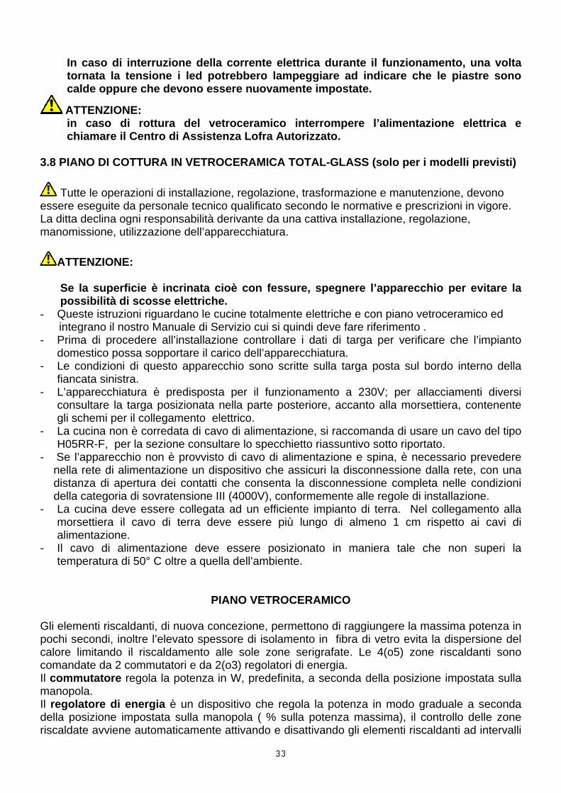
Gli elementi riscaldanti, di nuova concezione, permettono di raggiungere la massima potenza in pochi secondi, inoltre l’elevato spessore di isolamento in fibra di vetro evita la dispersione del calore limitando il riscaldamento alle sole zone serigrafate. Le 4(o5) zone riscaldanti sono comandate da 2 commutatori e da 2(o3) regolatori di energia. Il commutatore regola la potenza in W, predefinita, a seconda della posizione impostata sulla manopola. Il regolatore di energia è un dispositivo che regola la potenza in modo graduale a seconda della posizione impostata sulla manopola ( % sulla potenza massima), il controllo delle zone riscaldate avviene automaticamente attivando e disattivando gli elementi riscaldanti ad intervalli
34
regolari garantendo un riscaldamento preciso e uniforme. Es.: intervalli di riscaldamento brevi associati a lunghe pause indicano bassa temperatura; intervalli di riscaldamento lunghi intervallati da brevi pause indicano temperatura più alta. Con il regolatore di energia è possibile riscaldare la zona interessata del vetroceramico in modo totale o parziale. Disposizione delle piastre (vedi tabelle)
Caratteristica delle zone riscaldanti cucine con 4 piastre riscaldanti Posizione manopola e potenza corrispondente
Posizione Tipo comando
Zona utile riscaldata
Rotaz. manopola
Potenza max 1 2 3 4 5 6
Tutta Orario 2200W 100 % Anteriore sx
Regolatore di energia
Centrale Antiorario 750W 10 % 25 % 50 % 65 % 90 %
Posteriore sx Commutatore Tutta Antiorario 1200W 150 W 200 W 350 W 500 W 850 W 1200 W
Anteriore dx Commutatore Tutta Antiorario 1700W 180 W 300 W 450 W 750 W 1200 W 1700 W
tutta Orario 2400W 100 % Posteriore dx
Regolatore di energia
Circolare Antiorario 1500W10 % 25 % 50 % 65 % 90 %
Potenze elettriche assorbite
CUCINA MODELLO : Resistenza
suola
Resistenza cielo
Grill
Maxi Grill
Resistenza circolare
MXV66MFR – MXV76MFR PXV66MFR – PXV76MFR 1900W 700W 1800W 2500W 2000W
PXGV96AMFR - .96MFR 1750W 1000W 2000W 3000W 2500W
PXDV96AMFRE – .96MFRE FORNO GRANDE 1900W 700W 1800W 2500W 2000W
PXDV96AMFRE – .96 MFRE FORNO PICCOLO 1200W 500W 1000W - -
Caratteristica delle zone riscaldanti cucine con 5 piastre riscaldanti Posizione manopola e potenza corrispondente Posizione Tipo
comando Zona utile riscaldata
Rotaz. manopola
Potenza Max 1 2 3 4 5 6
Tutta Orario 2200W Anteriore sx
Regolatore di energia
Centrale Antiorario 750W 10 % 25 % 50 % 65 % 90 % 100 %
Anteriore dx Commutatore Tutta Antiorario 1200W 150 W 200 W 350 W 500 W 850 W 1200 W
Posteriore dx Commutatore Tutta Antiorario 1700W 180 W 300 W 450 W 750 W 1200 W 1700 W
Tutta Orario 2000W Posteriore sx
Regolatore di energia
Circolare Antiorario 1100W 10 % 25 % 50 % 65 % 90 % 100 %
Tutta Orario 2000W Centrale Regolatore
di energia
Circolare Antiorario 1100W 10 % 25 % 50 % 65 % 90 % 100 %

35
Calore residuo Il piano vetroceramico è diviso in 4 (o5) zone riscaldanti ed allo scopo di garantire una maggiore sicurezza è provvisto di segnalatori luminosi (indicatori di calore residuo) i quali si illuminano quando una zona è molto calda. I segnalatori rimangono accesi finché la zona riscaldata è calda, anche a piastre spente. Uso del piano vetroceramico All’atto della prima inserzione si consiglia di accendere le zone di cottura, una alla volta, per alcuni minuti al fine di eliminare l’eventuale umidità che si fosse accumulata nell’impasto isolante. Per evitare dispersioni di calore ed avere una resa ottimale conviene usare pentole con fondo piatto e spesso, inoltre per quanto possibile, siano di dimensioni simili alla zona di cottura usata. La zona riscaldata rimane calda per un certo tempo quindi conviene sfruttare questa prerogativa spegnendo la piastra qualche minuto prima che termini la cottura, in modo di ultimarla sfruttando il calore residuo accumulato dal vetro con conseguente risparmio di energia.
Si raccomanda di effettuare la pulizia quando il vetro si è raffreddato. Lavare il vetro con il tipo di liquido detergente di cui si fornisce un campione oppure acqua saponata, per lo sporco più resistente usare l’apposito raschietto fornito a corredo. Non usare materiale abrasivo come paglietta scotch bryte, spugnette metalliche o altro. Fare attenzione a non rovesciare dello zucchero durante la cottura perché si potrebbero formare delle incrostazioni impossibili da togliere; se dovesse succedere spegnere subito e pulire con il raschietto la zona interessata con il vetro ancora tiepido. Eventuali pentole in ghisa o con fondo ruvido tendono a lasciare delle tracce chiare che possono essere tolte con un panno imbevuto di aceto.
ATTENZIONE: Quando il piano è in funzione o il segnalatore di calore residuo è acceso fare molta attenzione, inoltre tenere lontano i bambini.
ATTENZIONE: in caso di rottura del vetroceramico scollegare l’alimentazione elettrica e chiamare il Centro di Assistenza Lofra Autorizzato
SCHEMA PER IL COLLEGAMENTO CUCINE CON PIANO VETROCERAMICA
Alimentazione Cavo alimentazione Diagramma collegamenti
220-240 V ~ 3 x 6 sq.mm H05VV-F
380-415V 3N~ 5 x 2,5 mmq H05VV-f
3.9 INSERIMENTO DEL FILTRO GRASSI SUL COPRIVENTOLA
ALL’INTERNO DEL FORNO MULTIFUNZIONE Posizionare le linguette A-B in corrispondenza dei fori del copriventola A1 - B1del fondo del forno. Fare pressione sulla staffa C in modo tale che le linguette si incastrino perfettamente nei fori A1 -B1. Bloccare il filtro grassi con la vite in dotazione .
Il forno ventilato deve funzionare con il filtro grassi inserito .

36
3.10 POSIZIONAMENTO DEI BRUCIATORI A GAS SUL PIANO DI LAVORO
Bruciatori ausiliario, semi rapido, rapido, superrapido: Per il corretto inserimento dei bruciatori, degli spartifiamma e dei coperchietti smaltati, sulla coppetta del piano di lavoro, bisogna seguire la sequenza riportata in figura . Fare attenzione che le guide del bruciatore sulla coppetta e dello spartifiamma sul bruciatore devono combaciare perfettamente. Bruciatore tripla corona: Accoppiare lo spartifiamma al supporto bruciatore in modo tale che non possa ruotare.
ATTENZIONE: i coperchietti del bruciatore tripla corona devono essere messi sempre nelle loro sedi, in caso contrario può propagarsi la fiamma anche all’interno (ritorno di fiamma) che deforma il bruciatore stesso per progressivo surriscaldamento.
Bruciatore pesciera: Inserire lo spartifiamma facendo coincidere il foro presente nella parte inferiore con la candeletta di accensione elettronica inserita nella coppetta del piano di lavoro. 3.11 GUIDE TELESCOPICHE (solo per i modelli previsti) Le guide telescopiche offrono una maggiore stabilità agli accessori del forno. Il posizionamento del cibo sulla griglia o sul vassoio risulterà più semplice e sicuro. Le griglie e i vassoi devono essere incastrati nelle apposite sedi delle guide. Durante la cottura e fintanto che il forno è caldo si consiglia di adoperare delle presine per le manipolazioni all’interno del forno stesso. 3.12 GRIGLIE CON DISPOSITIVO ANTICADUTA Le griglie sono dotate di sistema di sicurezza di estrazione per impedire che possano fuoriuscire completamente dal forno quando si estraggono parzialmente. Nell’inserimento verificare che il fermo anticaduta (vedi immagine) sia sempre sul retro. Le griglie vengono estratte dal forno solo se sollevate anteriormente. 3.13 ISTRUZIONI MONTAGGIO BRUCIATORE III SERIE
Il coperchio superiore dei bruciatori deve essere collocato nell’apposita sede con le due tacche di inserimento in corrispondenza
37
delle viti dei due cilindretti dello spartifiamma sottostante ed avvitato in senso orario (come indicato in figura).
ATTENZIONE Il montaggio non corretto del coperchio del bruciatore potrebbe causare il propagarsi della fiamma anche all’interno del bruciatore causando la deformazione dello stesso.
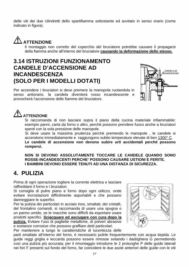
3.14 ISTRUZIONI FUNZIONAMENTO CANDELE D’ACCENSIONE AD INCANDESCENZA (SOLO PER I MODELLI DOTATI)
Per accendere i bruciatori si deve premere la manopola ruotandola in senso antiorario, la candela diventerà rosso incandescente e provocherà l’accensione delle fiamme del bruciatore.
ATTENZIONE Si raccomanda di non lasciare sopra il piano della cucina materiale infiammabile: esempio panni, carta da forno o altro, perché possono prendere fuoco anche a bruciatori spenti con la sola pressione delle manopole. Si deve usare la massima prudenza perché premendo le manopole , le candele si accendono immediatamente e raggiungono subito temperature elevate di ben 1300° C. Le candele di accensione non devono subire urti accidentali perché possono rompersi.
NON SI DEVONO ASSOLUTAMENTE TOCCARE LE CANDELE QUANDO SONO
ROSSE-INCANDESCENTI PERCHE’ POSSONO CAUSARE USTIONI E FERITE. I BAMBINI DEVONO ESSERE TENUTI AD UNA DISTANZA DI SICUREZZA.
4. PULIZIA Prima di ogni operazione togliere la corrente elettrica e lasciare raffreddare il forno e i bruciatori. Si consiglia di pulire piano e forno dopo ogni utilizzo, onde evitare incrostazioni difficilmente asportabili e che possano danneggiare le superfici. Per la pulizia dei particolari in acciaio inox, smaltati, dei cristalli, del frontalino comandi, si raccomanda di usare una spugna o un panno umido, se le macchie sono difficili da esportare usare prodotti specifici. Sciacquare ed asciugare con cura dopo la pulizia. Evitare l’uso di pagliette metalliche, di polveri abrasive e sostanze corrosive che possono graffiare detti particolari. Per mantenere a lungo le caratteristiche di lucentezza delle parti smaltate all’interno del forno, è necessario pulirle frequentemente con acqua tiepida. Le guide reggi griglia e leccarda possono essere rimosse svitando i dadi/ghiera G permettendo così una pulizia più accurata; per il rimontaggio introdurre le 2 prolunghe P delle guide laterali nei fori F presenti sul fondo del forno, far coincidere le due asole anteriori delle guide con le viti

38
già predisposte sulle fiancate, fissare le guide con i dadi/ghiera G. Non lavare il forno quando è ancora caldo e non adoperare sostanze o prodotti abrasivi.
Non permettere che sostanze acide o alcaline come: ACETO, CAFFÈ, LATTE, ACQUA SALATA, SUCCO DI LIMONE, SUCCO DI POMODORO, ECC. rimangano a contatto delle superfici smaltate o in acciaio per lungo tempo. Non utilizzare pulitoti a vapore per la pulizia dell’apparecchio.
Per la pulizia dei vetri interni della porta del forno, a seconda dei modelli togliere il profilo superiore aiutandosi con un cacciavite, sfilare i vetri dalle guide. Effettuare queste operazioni con la massima cautela e precisione. La pulizia dei bruciatori, dei coperchietti, degli spartifiamma va fatta periodicamente: si raccomanda di usare acqua saponata, prima di rimetterli nelle loro sedi asciugarli per bene e verificare che i fori degli spartifiamma siano tutti aperti.
5. AVVERTENZE PER IL RISPARMIO ENERGETICO ED IL RISPETTO DELL’AMBIENTE
Usare pentole di diametro adeguato alla potenza del bruciatore del piano di cottura , i diametri adatti sono riportati nel paragrafo 3.1. Non appena un liquido inizia a bollire , ridurre la fiamma quanto basta a mantenere l’ebollizione,si consiglia inoltre di continuare la cottura con il coperchio posto sulla pentola . Non interporre fra la pentola e la griglia dispositivi tipo sottopentola in rete . Mantenere sempre le parti dei bruciatori a gas pulite , verificare che i fori spartifiamma non siano intasati e che la fiamma sia distribuita regolarmente . Preriscaldare il forno per 10-15 minuti prima di introdurre il cibo scegliendo la temperatura corretta Non usare il forno con la porta aperta per riscaldare l’ambiente Controllare periodicamente l’integrità della guarnizione della porta del forno E’ possibile sfruttare l’inerzia termica , spegnendo il forno ca. 10 minuti prima del tempo previsto per la cottura . L’imballaggio dell’apparecchio deve essere riciclato presso i Punti di Raccolta Differenziata L’elettrodomestico fuori uso deve essere portato presso i Centri di Raccolta Differenziata La presenza del simbolo sottostante sta a significare che l’apparecchiatura rientra tra i “rifiuti nuovi” e quindi soggetta a raccolta separata (no rifiuti urbani).
Ai sensi dell’art.13 del Decreto Legislativo 25 luglio 2005, n.151 “Attuazione delle Direttive 2002/95/CE, 2002/96/CE e 2003/108/CE, relative alla riduzione dell’uso di sostanze pericolose nelle apparecchiature elettriche ed elettroniche, nonché allo smaltimento dei rifiuti.

39
Il simbolo del cassonetto barrato riportato sull’apparecchiatura o sulla sua confezione indica che il prodotto alla fine delle propria vita utile deve essere raccolto separatamente dagli altri rifiuti. L’utente dovrà, pertanto, conferire l’apparecchiatura giunta a fine vita agli idonei centri di raccolta differenziata dei rifiuti elettronici ed elettrotecnici, oppure riconsegnarla al rivenditore al momento dell’acquisto di una nuova apparecchiatura di tipo equivalente, in ragione uno a uno. L’adeguata raccolta differenziata per l’avvio successivo dell’apparecchiatura dimessa al riciclaggio ,al trattamento e allo smaltimento ambientalmente compatibile contribuisce ad evitare possibili effetti negativi sull’ambiente e sulla salute e favorisce il reinpiego e/o riciclo dei materiale di cui è composta l’apparecchiatura. Lo smaltimento abusivo del prodotto da parte dell’utente comporta l’applicazione delle sanzioni amministrative previste dalla normativa vigente.
CARATTERISTICHE DEI BRUCIATORI DEL PIANO E DEL FORNO TABELLA 1 Tipo di gas: Butano G30 - Pressione nominale =28-30mbar Propano G31 - Pressione nominale =37mbar Metano G20 - Pressione nominale =20mbar
Gas liquido Gas metano Portata termica nominale
g/h max
g/h min Portata termica nominale Tipi di bruciatore
By pass Ø 1/100 mm
Iniettori Ø 1/100 mm
kW max G30 G31
kW min G30 G31
Iniettori Ø 1/100 mm kW
maxkW min
Bruciatori del piano I serie Ausiliario: (piccolo) 27 50 1,00 73 71 0,29 21 21 77 1,00 0,29
Semi – rapido: (medio) 29 65 1,75 127 125 0,35 25 25 97 1,75 0,35
Rapido: (grande) 39 85 3,00 218 214 0,60 44 43 127 3,00 0,50
Tripla corona: 65 100 3,90 283 278 1,50 109 106 136 3,90 1,50
Pesciera: 65 85 3,00 218 214 1,50 109 107 120 3,00 1,50
Bruciatori del piano II serie normali e AEO, quadrifoglio Ausiliario: (piccolo) 27 50 1,00 73 71 0,30 21 21 72 1,00 0,30
Semi – rapido: (medio) 34 65 1,75 127 125 0,44 25 25 97 1,75 0,44
Rapido: (grande) 44 85 3,00 218 214 0,75 44 43 115 3,00 0,75
Tripla corona: 65 100 3,90 283 278 1,50 109 106 136 3,90 1,50
Dual Ø125mm: 70 46/85 3,90 283 278 1,80 130 127 130/75 3,9 1,80
Dual Ø145mm: 27/70 46/95 4,5 326 319 1,80 130 127 130/85 4,2 1,80/0,35
Dual Quadrifoglio 27/70 46/66 4,2 304 297 0,30 22 22 66/1,02 4,2 0,30
Bruciatori del piano III serie Ausiliario: (piccolo) 27 52 1,10 79 78 0,35 25 25 73 1,10 0,35
Semi – rapido: (medio) 34 65 1,75 127 125 0,45 32 32 98 1,75 0,45
Rapido: (grande) 44 82 2,80 203 200 0,75 54 53 122 2,80 0,75

40
Tripla corona: 65 97 3,70 268 264 1,50 109 133 133 3,70 1,50
Bruciatori del forno 60L : (60x50-60x60-70x50-70x60) - (carrello estraibile 80x60 90x60)- Ventilato gas Doppio forno 90x60
55 85 f/svasato 3,30 240 236 1,10 80 79 130
f/svasato 3,30 1,10
Forno gigante/ Forno gigante ventilato gas/ (...126GV...)
60 110 5,00 363 357 1,60 116 114 165 f/svaato 5,00 1,60
Vano ripostiglio: (80x50-90x60) 50 80
f/svasato 2,60 189 186 1,10 80 79 115 f/svasato 2,60 1,10
Vano ripostiglio e portabombola (90x50-90x60)
55 85 3,20 233 229 1,10 80 79 127 f/svasato 3,20 1,10
Bruciatori grill gas
60L : (60x50-60x60-70x50-70x60 )– (carrello estraibile 80x60 90x60) Doppio forno 90x60
- 77 2,30 166 164 - - - 115 2,30 -
Forno gigante / forno gigante ventilato (...126GVG...):
- 90 3,30 240 236 - - - 140 3,30 -
60L (60x60 – 70 x60) ventilato gas 85 2,60 188 185 - - - 130 2,6 -
CARATTERISTICHE DEL GLASS PLATE E DELLE PIASTRE ELETTRICHE TABELLA 2
CUCINA FORNO GIGANTE CON GLASS PLATE: 800 + 800 W
Corrispondenza tra la posizione della manopola e la potenza assorbita
Contrassegno della manopola e consumi in W
Diametro della piastra in mm
0 1 2 3 4
80 0 90 180 200 450
110 0 140 300 400 700
145 0 187 250 750 1000
180 0 300 600 900 1500
POTENZE ASSORBITE FORNO ELETTRICO CON TERMOSTATO
TABELLA 3
MODELLI
Resistenza suola
Resistenza cielo
Resistenza grill
Resistenza Maxi- grill
Resistenza circol.
Mod. Forno Elettrico statico: 60x50-60x60-70x50-70x60 1650 W 900 W 1500 W
Mod. Forno Misto: 70X50 - 70X60 1650 W 900 W 1500 W
Mod. Multifunzione: MX 66 ASMF 1650 W 600 W 1500 W

41
Mod. Multifunzione 60X50-60X60-70X50-70X60 1650 W 900 W 1500 W 2100W 2000 W
Mod. Grill Radiante: 60X60-70X60 1900 W 700 W 1800 W 2500W 2000 W
Mod. Grill Radiante: 90X60 1900 W 1000 W 2000 W 2500W 2000 W
Mod. Forno Gigante Multifunzione 1750 W 1000 W 2000 W 3000 W 2500 W
Forno sx 60l Doppio FORNO Forno dx 30l
1650 W
1200 W
900 W
500 W
1500 W
1000 W
2100 W
2000 W
Mod. Vano ripostiglio: 80X50-80X60 90X50-90X60 1400 W 700 W 1200 W
Mod. Vano Bombola: 90X50-90X60 1400 W 700 W 1200 W
Mod. Gas 60x50 – 60x60 – 70x50/60 – 90x50/60 1500W
Mod. Gas Gigante 1750 W
Mod. Gas Vano ripostiglio bombola (80x50/60 – 90x50/60) 1200 W
Mod. Gas 90x60 – 80x60 carrello estraibile 1500 W
Mod. Elettrico 90x60 – 80x60 carrello estraibile 1650 W 900 W 1500 W 2100 W 2000 W
Mod. Forno gigante gas ventilato 90X60 2000 W
Mod. Forno gas ventilato 60X60 – 70X60 1800 W
Forno 30 litri cucina ...D126... 1200 W 500 W 1000 W
CUCINE UP & DOWN (2 forni sovrapposti) TABELLA 4
DIMENSIONI Altezza 900-915 mm Larghezza 600 mm Profondità 600 mm (esclusa maniglia del forno) CARATTERISTICHE DEL BRUCIATORE DEL FORNO
Bruciatori
Forno superiore
Grill superiore
Forno inferiore
Portata termica nominale kW Portata termica minima kW Iniettore G20 20 mbar Ø 1/100 mm G30 30 mbar “ By-pass G20 20 mbar Ø 1/100 mm G30 30 mbar “
1,70 0,80
95 62
Reg. 42
2,70 ---
125 80
--- ---
2,40 1,00
110 72
Reg. 48
Temperatura forno UP: min.130°C – max. 270°C Temperatura forno DOWN: min.130°C – max. 270°C

42
CARATTERISTICHE ELETTRICHE DEL FORNO
FORNO SUPERIORE
Resistenza base Resistenza cielo Resistenza grill
1200 W 950 W 1900 W
FORNO INFERIORE
Vedi tabella 3
6. GARANZIE Il presente certificato di garanzia redatto da Nuova Lofra Sr.l., con sede in Torreglia (PD), Via Montegrotto 125; si riferisce alle condizioni di Garanzia Convenzionale del produttore nei confronti del consumatore e, dette condizioni non pregiudicano e sono rispettose dei diritti riconosciuti al Consumatore dal Decreto Legislativo 2 febbraio 2002, n.24 emesso in attuazione della Direttiva 1999/44/CE del Parlamento Europeo, nonché dal Decreto legislativo 6 Settembre 2005 n.206. Durata e condizioni di validità La Nuova Lofra S.r.l. garantisce l’elettrodomestico fornito per un periodo di ventiquattro mesi dalla data di acquisto, tale data potrà essere dimostrata esclusivamente dallo scontrino fiscale, dalla ricevuta fiscale, dalla fattura o altro documento fiscalmente valido, rilasciato dal Rivenditore autorizzato, riportante i dati dello stesso, gli estremi identificativi del prodotto e la data in cui è stata effettuata la vendita. Al fine di poter usufruire della garanzia si dovrà conservare questa documentazione unitamente al certificato di garanzia ed esibirlo al personale del Servizio di Assistenza Tecnica Autorizzato in caso di intervento. Per intervento in garanzia si intende la sostituzione o riparazione gratuita delle parti componenti l’elettrodomestico che risultano difettose sin dal momento dell’acquisto per vizi di fabbricazione, purchè il difetto sull’apparecchio sia stato denunciato entro i due mesi dalla scoperta e prima del termine della garanzia. Nell’ipotesi di irreparabilità del guasto o del ripetersi dello stesso, relativamente a parti essenziali dell’elettrodomestico, la Nuova Lofra S.r.l. si riserva, a suo insindacabile giudizio, di provvedere alla sostituzione integrale dell’apparecchio. La garanzia sul nuovo elettrodomestico continuerà fino al termine del contratto originario. Nel caso di non provati vizi di conformità che si verificano dopo il sesto mese dall’acquisto del prodotto, il Consumatore dovrà provare che essi esistevano a tale data, caso contrario dovrà versare al Centro Assistenza intervenuto un contributo per spese di trasferimento. Clausole di esclusione Si intendono esclusi dalla garanzia in tutti i casi di uso improprio dell’elettrodomestico ed in particolare in caso di uso non domestico (bar, ristoranti, attività commerciali, comunità, uffici, imprese, agriturismo, bed & breakfast, etc.) e, non copre tutte le parti sottoposte ad usura con il normale utilizzo (griglie, spartifiamma, guarnizioni, lampadine, maniglie, manopole, parti asportabili, le parti in vetro e smaltate, le tubazioni esterne, gli eventuali accessori e materiali di consumo etc.). Inoltre sono esclusi dalla garanzia tutti gli interventi ad elettrodomestici che dovessero risultare difettosi a causa di negligenza o trascuratezza nell’uso, mancata osservanza delle istruzioni ed indicazioni per il funzionamento dell’apparecchio riportate nel Manuale di Servizio, di errata installazione o manutenzione operata da personale non autorizzato o effettuata con ricambi non originali, di danni da trasporto, ovvero circostanze che, comunque, non possono farsi risalire a difetti di fabbricazione dell’apparecchio. Sono altresì escluse: tutte le operazioni di installazione,regolazione dei rubinetti e dei bruciatori con vari tipi di gas, le sostituzioni degli iniettori, la pulizia ordinaria periodica.

43
La Nuova Lofra S.r.l. declina ogni responsabilità per danni che possono derivare, direttamente o indirettamente, a persone, animali, o cose in conseguenza della mancata osservanza di tutte le prescrizioni e avvertenze indicate nell’apposito Manuale di Servizio e specialmente le avvertenze in tema di installazione, uso e manutenzione dell’elettrodomestico. Qualora l’apparecchio venisse riparato presso un Centro Assistenza Tecnica Autorizzato, in questo caso la Nuova Lofra S.r.l. non risponde per eventuali spese e rischi derivanti da trasporto, che saranno a totale carico dell’utente. Scadenza e tempi di intervento Trascorso il termine di ventiquattro mesi dalla data di acquisto, la garanzia decade e l’assistenza verrà effettuata addebitando le parti sostituite e le spese di manodopera secondo le tariffe vigenti in possesso del personale tecnico. Il personale tecnico autorizzato interverrà, nei tempi minori possibili, compatibilmente con le priorità di chiamata e con le esigenze di organizzazione, su richiesta dell’utente al Centro Assistenza Tecnica Autorizzato. IMPORTANTE : La presente Garanzia ha validità solamente in Italia.

ALL LOFRA COOKERS UNDERGO TESTS FOR THE SEALS OF THE GAS PIPES, SETTING THE MINIMUM AND MAXIMUM OUTPUT OF THE GAS BURNERS; TESTS TO THE ELECTRICAL SYSTEMS; EARTH CONTINUITY – DIELECTRIC RIGIDITY – INSULATION RESISTANCE – LEAKS AND ABSORPTION CURRENTS, ALL CARRIED OUT USING SPECIFIC ELECTRONIC INSTRUMENTS THAT GUARANTEE UTMOST RELIABILITY.
INDEX WARNINGS AND TIPS ............................................................................................................. 45 1. INSTALLATION..................................................................................................................... 51
1.1.VENTILATION................................................................................................................................................................................51 1.2.DISCHARGE OF FUEL GASES ....................................................................................................................................................52 1.3.POSITIONING THE COOKER ....................................................................................................................................................52 1.4.CONNECTION TO THE GAS SUPPLY: CURRENT INSTALLATION STANDARDS ...............................................................54 1.5. CONNECTION TO THE ELECTRICITY SUPPLY ........................................................................................................................55 1.6.CONVERTING THE GAS-SUPPLY TO THE HOB BURNERS ...................................................................................................56 1.7.REGULATING THE MINIMUM OUTPUT OF THE HOB BURNERS.........................................................................................56 1.8.CONVERTING THE GAS-SUPPLY TO THE OVEN BURNERS AND GAS GRILL...................................................................56
2. MAINTENANCE .................................................................................................................... 57
2.1. GAS SUPPLY RUBBER PIPE..........................................................................................................................................................57 2.2. ELECTRICITY SUPPLY CABLE.......................................................................................................................................................57 2.3. REMOVING AND FITTING THE OVEN DOOR.......................................................................................................................57 2.4. REPLACING THE LIGHT BULB ....................................................................................................................................................58 2.5. GLASS COVER .............................................................................................................................................................................58
3. USING THE COOKER........................................................................................................... 58
3.1. USING THE COOKING HOB....................................................................................................................................................58 3.2. OVEN PERFORMANCE ..............................................................................................................................................................59 3.3. USING THE GRILL........................................................................................................................................................................60 3.4. ROTISSERIE (only certain models) ..............................................................................................................................................61 3.5. MINUTE TIMER ............................................................................................................................................................................61 3.6. MULTIPLE-FUNCTION COOKERS .............................................................................................................................................62 3.7. COOKING HOB WITH GLASS-PLATE (only certain model)...................................................................................................69 3.8. GLASS CERAMIC WORKTOP....................................................................................................................................................72 3.9. FITTING THE FAT FILTER TO GIANT MULTIPLE-FUCTION OVEN.........................................................................................74 3.10. FITTING THE GAS BURNERS TO THE HOB ..........................................................................................................................74 3.11. TELESCOPIC RUNNERS (only for certain models).................................................................................................................74 3.12 GAS BURNER SERIES 3 FITTING INSTRUCTIONS................................................................................................................74 3.13 GLOW PLUGS OPERATING INSTRUCTIONS (ONLY ON SELECTED MODELS) .............................................................75
4. CLEANING ............................................................................................................................ 75 BURNER SPECIFICATIONS..................................................................................................... 77 TABLE ...................................................................................................................................... 77

45
WARNINGS AND TIPS
⇒ This appliance has been designed for domestic use only.
⇒ These instructions are only valid for
the country indicated in the identification symbols on the appliance (see the image).
⇒ All installation, adjustments, gas-conversion and
maintenance operations must be carried out by qualified engineers, in accordance with the enclosed instructions and current installation standards. The manufacturers accepts no liability for faulty installation, setting, handling and use of the cooker.
⇒ Information about this model and its features is displayed on the appliance plate.
⇒ This appliance is not intended for use by person (including children) with reduced physical, sensory or mental capabilities, or lack of experience and knowledge, unless they have been given supervision or instruction concerning use of the appliance by a person responsible for their safety.

46
⇒ For any service repairs to the appliance, show the service engineer the guarantee and the till receipt with the date of purchase.
⇒ Before carrying out any maintenance or conversion operations, unplug the cooker from the mains and shut off the gas upstream of the appliance. If any components and/or accessories need replacing, only original Lofra spare parts must be used. Only qualified technicians may perform installation and maintenance operations.
⇒ Keep the instruction handbook near the cooker, so that if can be consulted at any time. This way, the instructions and tips are close at hand for correct use and optimum performance.
⇒ Before using the cooker remove the plastic protection from the stainless steel, aluminium and/or painted parts in order to prevent it melting. The utmost care must be taken when removing this protection so as to avoid damaging the protected parts.
⇒ When the cooker is in use keep children at a safe distance, as the outside of the cooker can heat up, and they should be kept away until the cooker has completely cooled down. Likewise children should not play with or use the cooker controls unsupervised.
⇒ Periodically check that there are no gas leaks from the connection pipe between the cooker

47
and the bottle or supply line; replace upon expiry.
⇒ This appliance is not intended for use by person (including children) with reduced physical, sensory or metal capabilities, or lack of experience and knowledge, unless they have been given supervision or instruction concerning use of the appliance by a person responsible for their safety.
⇒ During use the appliance becomes hot. Care should be taken to avoid touching heating elements inside the oven.
⇒ Warning: Accessible parts may become hot during use. Young children should be kept away.
⇒ The appliance and its accessible parts become hot during use. Care should be taken to avoid touching heating elements. Children less than 8 years of age shall be kept away unless continuously supervised.
⇒ This appliance can be used by children aged from 8 years and above and persons with reduced physical, sensory or mental capabilities or lack of experience and knowledge if they have been given supervision or instruction concerning use of the appliance in a safe way and understand the hazards involved. Children shall not play with the appliance. Cleaning and

48
user maintenance shall not be made by children without supervision.
⇒ The installation instructions for cooking ranges that are placed on the floor shall state that if the range is placed at a base, measures have to be taken to prevent the appliance slipping from the base.
⇒ Periodically check that there are no gas leaks in the pipe that connects the cooker to the gas bottle or the supply line; replace it upon expiry
⇒ When the cooker is not in use, ensure that all the knobs are in the off position; furthermore, if it is unused for a period of time, shut off the gas bottle valve and the supply valve, as well as the appliance’s mains electricity supply.
⇒ Keep the burners, covers and flame diffusers clean in order to ensure optimum operation.
⇒ Unattended cooking on a hob with fat or oil can be dangerous and may result in fire. NEVER try to extinguish a fire with water, but switch off the appliance and then cover flame e.g. with a lid or a fire blanket.
⇒ Danger of fire: do not store items on the cooking surfaces.
⇒ During use the appliance becomes hot. Care should be taken to avoid touching heating elements inside the oven.

49
⇒ Do not use steel wool, abrasive powders and corrosive substances that could scratch. Do not use steam cleaners to clean the appliance.
⇒ Before using the oven for the first time, we recommend leaving it on for one hour at the maximum temperature. Doing so may create smoke and unpleasant smells, which are caused by the glue in the heat insulation or oiled plates. To get rid of these odours, air room e.g. opening a window.
⇒ Some models are fitted with an aluminium tray,
ideal for baking pastries (180-200°C). Max. load 3 kg.
⇒ The cover is made of hardened glass. Do not
close it when the burners or electric plate are on, or still hot, as this could break the glass and create a hazard.
⇒ If the glass ceramic surface should ever get broken, unplug the appliance and contact an authorized centre.
⇒ Remove any objects from the top of the cover before opening it.
⇒ Do not discard packaging, accessories or other
parts of the appliance into the environment. If

50
possible, take them to recycling bins or a recycling plant.
⇒ In the cookers that do not have a power cord, this manual indicated the type of cable to use, taking into account the temperature of the rear surface of the device.
⇒ The instructions show the correct installation of shelves and trays.
⇒ Stationary appliances not fitted with means for disconnection from the supply mains having a contact separation in all poles that provide full disconnection under overvoltage category III, the instructions state that means for disconnection must be incorporated in the fixed wiring in accordance with the wiring rules
LIFTING ISTRUCTIONS
fig. 1
fig.2
To lift the cooker open the oven door and lift by the oven cavity and the over hang at the rear of the appliance (fig 1 & 2).
fig. 3
NO
fig. 4

51
DO NOT lift the cooker by the overhang of the hob top at the front of the appliance or by the door handle (fig 3 & 4). Lifting the appliance by the hob can cause the securing brackets to break and damage the gas pipes to the burners on the hob. Lifting the appliance by the door handle can chip or break the outer door glass. Any resulting damage is NOT covered by the guarantee.
1. INSTALLATION
This appliance shall be installed in accordance with the regulations in force and only in a well ventilated space. Read the instructions before installing or using the appliance. In the UK the regulations and standards are as follows: In your own interest and that of safety, it is law that all gas appliances be installed by competent persons. CORGI registered installers undertake to work to safe and satisfactory standards. Failure to install the appliance correctly could invalidate any warranty of liability claims and lead to prosecution. The cooker must be installed in accordance with: All relevant British Standards / Codes of Practice, in particular BS 5440 Part 2 2000 and:
• For Natural Gas – BS6172: 1990 and BS6891: 1988 • For LP Gas – BS5482 Part 1 (when the installation is in a permanent dwelling),
Part 2, (when the installation is in a caravan or other non permanent dwelling), or Part 3 (when installing is in a boat).
• The Gas Safety (Installing and Use) regulations 1994 (as amended). • The relevant Building /IEE regulations.
The cooker may be installed in a kitchen / kitchen diner but NOT in a room containing a bath or shower. If the appliance is for use on LPG it must not be fitted below ground level, i.e. in a basement.
1.1.VENTILATION The room containing this cooker should have an air supply in accordance with BS 5440: Part 2: 1989
- All rooms require an openable window, or equivalent and some rooms will require a permanent vent a well.
- For room volumes up to 5 m3 an air vent of 100 cm2 is required. - For room volumes between 5 m3 and 10 m3 an air vent of 50 cm2 is required. - If the room is greater than 5 m3 and has a door that opens
directly to the outside, then no air vent is required. - If there are other fuel burning appliances in the same room BS
5440: Part 2:1989 should be consulted to determine the air vent requirements.
- This appliance should not be installed in a bed sitting room of less 20 m3 or in bathroom or shower room.

52
1.2.DISCHARGE OF FUEL GASES Cooking appliances must always discharge the flue gases into special hoods (fig.1-C), which must be connected to chimneys, flue pipes or have directly access to the outside. If it is not possible to connect a hood, an electric fan can be fitted to a window or a wall (fig.1-E), which must be turned on when the cooker is on, as long as ventilation standards are strictly adhered to. 1.3.POSITIONING THE COOKER a) Built-in cooker: type Y – class 2 subclass 2/1 Cookers in this class can be fitted between two units, unless the side in contact with the cooker is higher than the hob. In this case, the unit must stand at least 5 cm away from the top of the hob. If the cooker has a baseboard fitted, a 2cm vent must be made in the front along the entire width of the cooker. b) Free standing cooker: type X – class 1; point a) also applies to this class, with the exception that one side of the cooker must be left free so that the flexible rubber gas piping, can be inspected. After unpacking the cooker, remove the plastic protection from the stainless steel, aluminium and/or painted parts to avoid it melting. The utmost care must be taken when removing this protection so as not to damage the protected parts. Now the feet can be fitted. They must be fixed to the ends of the slits on the cooker pedestal. Their height can be adjusted in order to line the cooker up with other units. Ensure that the cooker is perfectly stable. Fit the burners, the flame diffusers and the grids into their seats on the hob (see paragraph 3.9). Some models come with rubber pads that prevent the steel hob surface from being scratched. Fit them to the central pan grid made of chrome-plated rod. LEG FITTING INSTRUCTIONS
Figure1. When fitting the washer to the leg bolt make sure the burr on the washer is facing upward away from the leg top.

53
Figure 2. Leg assembly with washer fitted correctly. The lower part of the leg will unscrew to adjust the height and level of the cooker.
Figure 3. Leg insert cut out on base of oven. To fit the legs to the appliance lie the cooker flat on its back and fit all four legs. DO NOT fit legs to the cooker by tilting the appliance, doing so may damage the leg assembly.
Figure 4. Insert washer fitted to top of leg into base of cooker and slide the leg along the channel.
Figure5. Screw the leg up tight so the oven base is clamped between the washer and the top of the leg. Once all four legs have been fitted lift cooker onto the legs taking care to distribute the weight evenly onto all four legs at the same time. DO NOT tip the appliance onto its legs, always lift the appliance onto its legs. (This will require two people)
For the installation anchor the cooker by using the supplied kit referring to the relevant drawing. We provides two brackets, which will serve to anchor the wall-terminal of the cooker. We must fix the brackets to the wall, following the instructions of the drawings. We must then slightly lift the cooker to let in the bracket on the crease of the wall-terminal or working top cooker.

54
Note: When the burners are alight, there must not be any draughts inside the room in that they may affect the flame or even blow it out. (PLEASE NOTE: The fixing hook is not provided as the type will depend on the construction of the wall to which it will be drilled and fitted. The installer should provide the fixing hook).
1.4.CONNECTION TO THE GAS SUPPLY: CURRENT INSTALLATION STANDARDS The cooker should be connected according BS 6172-1990, using either a rigid or flexible connections. a) Class 2 (Built-in cooker sub-class 2/1): use a continuous
flexible stainless steel pipe, as per current installation standards, which can be extended to a maximum of 2000 mm.; the ends of the pipe must be fitted with an ISO 228/1coupling and gasket or an ISO 7/1 threaded coupling with mechanical gasket.
b) Class 1 (Free-standing cooker): Class 2 instructions also apply. In addition, a non-metallic flexible pipe can be used as long as it complies with current standards and the following installation instructions are observed: the pipe must be longer than 400 mm and shorter than 1500 mm; it must not exceed 50àC in any point; it is not pulled or twisted; it cannot be choked and the entire edges, sharp corners or other similar hazards.
Before connecting the non-metallic flexible pipe, the pipe holder and gasket supplied with the cooker and/or available form the reseller must be fitted to the
pipe/gas train on the back of the cooker. ONLY FOR MODELS: XR96GV/C, XR96MF/C
For connection to: - Methane gas: the pipe must have an internal diameter of 13 mm, be fitted to the pipe holder
and then blocked with a specific clamp as per current installation standards; - Liquid gas (bottle): the pipe must have an internal diameter of 8 mm, be fitted to the pipe
holder and then blocked with a specific clamp as per current installation standards. The bottle must be fitted with a pressure reducer as per current installation standards.
Cookers with bottle cupboard IF INSTALLATION STANDARDS PERMIT. These cookers are designed prepared for use with bottle of liquid gas (size Ø 270 mm, height 600 mm). They are fitted with two attachments for the gas connection: one inside the cupboard and one on the back hand side. The bottle cupboard attachment is sealed with a cap and a gasket, while the other end is open. If the bottle cupboard attachment is used, the cap must be replaced with the pipe holder must be connected with a flexible pipe, which must follow the route shown in the

55
adjacent diagrams and/or on the adhesive plate fitted inside the bottle cupboard door. After connection, ensure that there are no gas leaks by using a specific instrument or soapy water. 1.5. CONNECTION TO THE ELECTRICITY SUPPLY The flexible mains lead is supplied connected to a BS 1363 fused plug fused plug fitted with a fuse of 13 amp capacity. If you need to replace the plug for any reason, it should be carried out as outlined below: WARNING: THIS APPLIANCE MUST BE EARTHED.
The wired in the mains lead are coloured in accordance with the following code: Green & Yellow = Earth – Blue= Neutral – Brown= Live As the colours of the wires in the mains lead of the appliance may not correspond with the coloured markings identifying the terminals in your plug, proceed as follows:
1. The wire which is coloured Green & Yellow must be connected to the terminal marked E (Earth) or coloured Green.
2. The wire which is coloured Blue must be connected to the terminal marked N (Neutral) or coloured Black.
3. The wire which is coloured Brown must be connected to the terminal marked L (Live) or coloured Red.
The plug and socket must be accessible after installation. Should the mains lead ever need replacing it is recommended that this operation is carried out by a qualified electrician who will replace it with a lead of the same size and temperature rating. If a fixed instrument has not any cable nor pin, or any other device which assures the worknet disconnection, with a distance of opening of the contacts that allows the complete disconnection in the conditions of overvoltage category III, the instructions have to inform that such disconnection devices have to be provided for by the supply mains in conformity with the installation rules. Note: For EMC requirement (IEC / EN 61000-3-3) kitchen (PD96MFRE / C) The connection is contingent on the network at the point of interface with an impedance of 0.36 ohms or less.
Terminal connection diagram with cable pre-installed
220-240 V ~

56
1.6.CONVERTING THE GAS-SUPPLY TO THE HOB BURNERS Burners: auxiliary, semi-rapid, rapid, treble crown, fish kettle. These burners are all fitted with injectors designed to create a primary input of air gauged for each type of gas. This means that the air regulation does not have to be regulated. Proceed as follows in order to convert from one type of gas to another:
remove the grids, covers, holed flame diffuser and the burner supports;
replace the holed injectors as indicated in C according to the type of gas used (see table 1); put the burner supports, flame diffusers, covers and grids back in position;
regulate the minimum output following the instructions in paragraph. 1.7.REGULATING THE MINIMUM OUTPUT OF THE HOB BURNERS Normal/valve taps Ignite the burners and turn the know to the maximum position. Remove the knob and insert a small flat-head screwdriver into the holes on the side of the control panel, in accordance with the type (fig. A). Loosen the by-pass screw by two turns in an anti-clockwise direction and rotate the rod to the minimum position. Adjust the previously loosened screws until the flame is lowered but stable, even when rapid changes are made from the maximum to the minimum position with the burner cold. If safety taps are fitted, let the burner run on minimum for a few minutes to ensure that the device does not cut in. If it does, increase the minimum. N.B. For liquid gas settings, the burner minimum must be set by fully tightening the tap by-passes. 1.8.CONVERTING THE GAS-SUPPLY TO THE OVEN BURNERS AND GAS GRILL Oven burners: To have access to the oven injector proceed as follows:
open the oven door and remove the oven base; unfasten the screw that secures the burner to the inside of the oven (in the giant oven it
is fixed to the side wall of the muffle) and remove the burner from its seat being careful not to damage the thermocouple fixed to it;
replace the holed injector in accordance with the type of gas used (see Table 1) put the burner back into its original position.
Setting the oven thermostat minimum To set the minimum, proceed as follows:
open the over door; light the oven burner and set it to maximum, close the door and wait for about 10 minutes
(or the time required for the oven to heat up to about 230°C); remove the oven knob and, using the hole in the control panel, according to the
thermostat type (Fig. C), loosen the by-pass screw of the thermostat by two turns; replace the knob and turn it to the minimum position, remove the knob and adjust the
previously loosened screw until the flame is lowered but stable, even when rapid

57
changes from maximum to minimum are made and the oven door is opened or closer quickly.
N.B. For liquid gas setting, the oven burner minimum is set by fully tightening the thermostat by-passes. Gas grill burners To convert the gas to this type of burner, see the "oven burner" instructions above. The only difference is that the burner is in the top of the oven, and there is no need to set the minimum because the burner always works at full power.
2. MAINTENANCE
WARNINGS: Before carrying out any maintenance or conversion operations, turn off the electricity supply and close the gas upstream of the appliance. If components and/or accessories need replacing, use only Lofra spare parts only. All the operations hereunder must be carried out by qualified technicians in accordance with the enclosed instructions and current installation standards.
2.1. GAS SUPPLY RUBBER PIPE The condition of the gas supply pipe should be checked periodically (once a year) and replaced by the date printed on the outside of the pipe and if there are signs of cracking, cuts, scratches or burns, or if it is no longer flexible but hard and plastic. The pipe must be suitable for use with liquid gas and comply with the applicable standards. 2.2. ELECTRICITY SUPPLY CABLE If the electricity supply cable needs replacing, therefore only authorised LOFRA technicians may replace it. Use HO5FVV-F cables only. The earth wire (yellow/green) must be at least 2 cm longer than the other two phase wires (fig. 5 B). This ensures that the electrics are safe should the wire be pulled accidentally. For the cookers with a gas oven and an electric grill, use a 3x1,5 mm² HO5RR-F cable, for cookers with electric oven and grill, use a 3x1.5 mm² HO5VV-F cable with a maximum external diameter of 9 mm. In the case of current exceeding 16A shall have the power section 2.5 mm². 2.3. REMOVING AND FITTING THE OVEN DOOR
Open the oven door completely, insert the anti-rotation device (A) in the hook of the hinge rods. Hold the oven door by the sides and slowly close it until you can feel a certain resistance; simultaneausly lift the door and force it towards its closed position in order to slide it out by freeing the hinge lock from the kitchen’s body. To refit the door repeat the above instructions in reverse making sure the hinge lock is correctly fitted.
For the CURVA models insert an anti-rotation hinge in the appropriate holes. Hold the door by the sides and slowly close it until you can feel a certain resistance; now, while forcing the door closed, lift it in order to slide it out by freeing the hinge lock from the kitchen. To refit the door repeat the above instructions in reverse making sure the hinge lock is correctly fitted.

58
Avoid using abrasive materials or any kind of sharp metal scraping tool to clean the glass oven doors to prevent them from getting scratched or cracked.
2.4. REPLACING THE LIGHT BULB Turn the cooker off at the mains before replacing the bulb. Open the oven door, remove the protective glass cover, replace the light bulb (CAUTION: it must be resistant up to 300°C) and replace the glass protection. 2.5. GLASS COVER To assemble the cover put the hinges into the special spaces in the wall protection of the cooker fitting into the existing slits (A), lift the cover up in vertical position (B) and push down until the hinges go to their place (C). To disassemble the cover make the contrary of the above-described operation. A B C
3. USING THE COOKER WARNINGS: - If the burner flames accidentally go out, turn off the KNOB and wait for at least one minute
before igniting. - Using a gas cooker produces heat and humidity in the room where it is installed. Ensure the
room is well ventilated by keeping all the natural air vents open or by installing an extraction hood with flue pipe.
- Intensive or extensive use of the cooker could may require supplementary ventilation e.g. opening a window, or more efficient ventilation e.g. increasing the capacity of the mechanic ventilation, if installed.
- The front control panel has one or two lights, depending on whether the oven is gas or electric. If the cooker has a gas oven a green light will illuminate when a heated accessory is turned on (ELECTRIC PLATES, ROTISSERIE, ELECTRIC GRILL). If the cooker has an electric oven, there is a green light and also a yellow light, which turns on and off when the THERMOSTAT cuts in to regulate the oven temperature. 3.1. USING THE COOKING HOB Gas burners
Automatic electronic ignition built into the knob: turn the knob to the maximum position push it in and the burner lights up automatically. • No gas supply (knob turned off)

59
Maximum gas supply Minimum gas supply To obtain minimum supply, turn the knob in an anti-clockwise direction until the indicator points to the small flame . Safety device: once the burner is on, keep the knob pressed for at least 5 seconds and then release it. The burner remains alight due to the thermocouple that keeps the gas flow by means of a safety valve, which shuts off the gas flow should the burner go out accidentally.
Burner performance: a variety of pans with a minimum diameter of 120 mm can be used on the “medium and small” burners. The pans must not have concave or convex bottoms, but be perfectly flat as shows in figure. For optimum performance, use the saucepans shown in figure, i.e. the flames must not stay beyond the bottom of the pan. When a liquid starts boiling, lower the flame as much as possible, but keep it on the boil. For safety reasons, we recommend using pans with the following diameters on the various burners(see tables). For emergency reasons we advise I use it of the following pots with diameters to overlap to the burners: auxiliary, semi-rapid, rapid, triple ring, fish burner.
Burner Diameter min.(cm) Diameter max(cm) Small (auxiliary) 10 14 Medium (semi –rapid) 15 20 Large (rapid) 21 26 Triple ring (ultra-rapid) dual Ø125mm AEO 24 26 Dual Ø145mm AEO four-leaf 26 30 Note. To second of the conformation of the plan holding one distance between the edges of the pots of minimum 10mm.
Electric plates The first time the plate is turned on or if it has not been used for a long time, it should be turned on and left on for 30 minutes in position 1 on the selector switch in order to dry out any humidity absorbed by the insulating cover. To avoid heat dispersion and damage to the plate, use flat bottomed pans that have the same diameter as the plate, no more no less. Dry the bottom of the pan before putting it on the plate. When the plate is on, never stand an empty pan on it, or leave the plate on without a pan. Turning the plates on – centre the pan on the plate and turn the corresponding knob to the required position (see Table 2). The increasing numbers indicate greater power.
3.2. OVEN PERFORMANCE Gas oven The oven burner must always be ignited with the oven door open. All Lofra cookers are fitted with valve thermostats which not only regulate the temperature inside the oven, but also stop the gas flow should the burner go out accidentally, thus avoiding leakage of unburned gas.

60
For the best results, we recommend preheating the oven for 10+15 minutes before putting the food in. The oven door should be opened as little as possible in order to avoid any rapid changes in oven temperature, which may compromise the cooking results. Ignition – open the oven door, press and turn the oven knob (symbol ) in an anti-clockwise direction to the maximum position. The burner can be ignited with press into the knob. When the burner alights, keep the knob well pressed in for 5+10 seconds and then release it. The burner stay alight by heating the thermocouple that opens the safety valve and keeps the gas flowing. After carrying out these operations, close the oven door and turn the knob to the required temperature. The automatic ignition device (electronic ignition built into the knob) must not be activated for more in 15 seconds. If the burner does not ignite after this time, release the knob and wait for at least one minute before trying to ignite the burner again. In some models, a special safety device discharges electricity so that the burner only ignites when the door is open. Electric ovens STATIC OVENS: heat produced inside the oven by electric elements fitted in the top (sky) and bottom (base) of the oven; these elements can work together or independently. This gives more even cooking, for example when the cooking time is almost up, the food may need more heat at the top or the bottom. The temperature is kept constant by the thermostat, which can be set between 50 and 250°C. During cooking, only open the oven door when strictly necessary. During this cooking method, humidity loss from the food is slow and uniform. FAN OVENS; heat is produced by the forced circulation of hot air inside the oven. A circular element next to a motorised fan heats the air, which this fan circulates evenly and rapidly. Indeed, this type of oven cooks faster than traditional ovens, hence you should set your cooking temperatures 10-20°C lower than normal. Once again the thermostat maintains the oven at the pre-selected temperature, which range from 50°C and 250°C. The oven need only several dishes together without altering the flavours in any way. Switching on the multiple-function oven: turn the oven knob marked by the or the symbol to the right and set the required temperature, in accordance with the cooking method. Mixed ovens (gas/electric). Certain models of cooker have both gas and an electric ovens. To switch on the oven, see the previous paragraphs detailing "gas ovens" and "electric ovens". For safety reasons, they must be used separately. 3.3. USING THE GRILL The food is laid on the oven grill, which then be placed inside the oven. The grill’s position depends on the type of food, e.g. flat or thin meat should be placed on the level closest to the grill, while a roll of meat, or poultry, etc. should placed on the middle level. The drip tray should be fitted on the guides below the grill. Using the gas grill: We recommend using the gas grill to complete oven cooking, therefore for 15-20 minutes at most; both for better cooking quality and for lower consumption and reduced cooking times. All the gas grills have a safety device that automatically stops the gas flow if the burner accidentally goes out, A special two-way thermostat activates the oven burner on the grill burner. The gas grill cannot be regulated as it always works at maximum. They can be turned on manually or elettronically; refer to the indications given for the gas oven burner.

61
Using the elettrical grill: a) MODELS WITH GAS OVEN: to avoid the oven and the grill being used at the same time,
the oven knob must be set in the off position for safety reasons, i.e. at the • symbol. Then press the electric grill button which is on the control panel.
b) MODELS WITH ELECTRIC OVEN: are switched on by turning the oven knob to the right (clockwise) until the indicator points to the grill symbol (last knob position).
c) MODELS WITH MULTIPLE-FUNCTION OVENS: switch on the grill by turning the functions knob to right (F) and set it to the required grill position . Then turn the oven thermostat knob (T) and set the temperature to 200°C. The oven door must stay closed.
d) MODELS WITH MULTIPLE FUNCTION OVEN AND RADIATING GRILL: the grill cooks by radiating heat , which is produced by a special element that reaches a temperature of approx. 800°C in a few seconds. It produces infrared rays which a transparent pyroceram plate used to ensure ultra-quick cooking times. The layout of the heating filament and the high insulation level mean that heat distribution is concentrated on the surface of the pyroceram plate, thus ensuring even cooking and energy savings. The plate should be cleaned once the oven has cooled down. The plate can be cleaned more thoroughly and more easily, and it protects the heating element from splashes and fat.
e) MODELS WITH CHANGEABLE GRILL Grill operation: switch on the grill by turning the function knob to the right (F) and set it to required grill position. Then turn the oven thermostat knob (T) and set temperature to 200°C, regulate the knob on the changeable grill on the position MIN. – MED. – MAX. according to the utilization. The oven door must stay closed.
ATTENTION: if the pyroceram plate brakes, turn off the power supply and call your Authorised Lofra Service Centre.
ATTENTION: if the surface of the grill is cracked, switch off the switch to the appliance to avoid the possibility of electric shock.
WARNING: The accessible parts get very hot when the grill is in use. Keep children at a safe distance.
3.4. ROTISSERIE (only certain models) The rotisserie is used for spit-roasting using the oven and the grill. After placing the drip tray on thebottom shelf, follow these procedures: - fit the handle to the spit, skewer the food onto the spit and secure it at either end with the
two adjustable forks (to avoid the rotisserie motor overworking, try to distribute the food on the spit as evenly as possible)
- place the spit rod into the support and then into the motor shaft; - loosen the split handle and start the motor with the switch on the front control panel (fig.
12); then turn on the grill. 3.5. MINUTE TIMER This mechanical minute timer goes from 0 to 60 minutes and sound a bell when the preset time is up. To start the timer, turn the knob to the right and set it to the required time. The knob automatically returns to zero, and the bell rings at the end of the preset time.

62
Warning: the knob must not be turned in anti-clockwise besides the hand symbol, otherwise you can break the timer.
3.6. MULTIPLE-FUNCTION COOKERS The multiple function cookers are distinguished by the fact that the heat, inside the oven, can be spread naturally (convection) or forced (with the fan). Thanks to this, by turning the selector to the desired function, 8 different types of cooking with separate temperature (thermostat knob) regulation are possible between 50 and 250°C; therefore even the most varied cooking requirements are satisfied. Depending on the models, these cookers have an end of cooking timer or a digital electronic programmer. Cookers with timer : Cookers with this device allow uninterrupted manual working and programming the cooking time of the oven between 0 and 120 minutes. Uninterrupted manual working: set the type of cooking and the oven temperature using the “A” and “B” knobs respectively, turn the timer knob “C” in an anti-clockwise
direction until it coincides with the symbol. ELECTRONIC PROGRAMMER Lofra new electronic programmer is a high-technology component which, by using only one knob, allows to use all the functions that usually are made with more than one knob. Beyond to turn in clockwise and anti-clockwise direction, it can be pressed as a push button. This simple system easily allows to use all the cooking programmes of your new cooker. To make easy the explanation of the functions next to the text you will find a descriptive Image about the operation that you will have to carry out.
TURN THE KNOB
PRESS THE KNOB
LED Cooking Time
LED Cooking Programming
LED Timer
Forno
ON Forno OFF
At the moment of the first ignition the display blinks.

63
How to program time at the first ignition of the system.
Turn the knob and program hour and minutes.
Confirm pressing completely the knob.
How to regulate the hour.
To modify the hour after the first time, keep pressed the knob for 3 seconds, and carry out the previous operation.
Minute counter function.
Turn the knob to program the times of the “minute counter”.
The display shows the remaining time and the led blinks, at the end the display shows “END” and a sound warning is in function.
The sound alarm is repeated for 10 minutes. It is intermittent in the first 30 seconds, after you can hear a warning every 15 seconds. To interrupt press the knob.
Turning the knob in clockwise direction a new count is in function again and you have the possibility to modify the time. To interrupt the function you have to turn the knob until 0 or to press the knob.
Cooking time function.
Turning the knob with the lighted oven the function “cooking time” is activated,
the led blinks and the remaining time is showed. When on the display “ END” appears, the oven switches off and a sound warning is in function.
To come back to the hour press the knob or put the oven knob in off position. Turning it to right a new count is in function again, the oven switches on and it is possible to program a new time too.
To interrupt the function turn the knob until 0 or press the knob.
To connect a “minute counter” function during the cooking with the lighted oven and “cooking time” not connected, to be advised without the switching off of the oven, it is sufficient pressing the knob 2 times, the “minute counter” function is on with a pre-programmed time of 5 minutes.
It is possible to modify the time operating on the knob.

64
Note: If the knob is pressed twice consecutively it is possible to regulate the timer at intervals of 5 minutes. Push once more to fix the desired time.
Function “ cooking programming” with delayed starting.
Pressing the knob with the switched off oven, the function “cooking
programming” is on, the blinking led switches on, you program the hour of automatic lighting with the knob and you confirm it pressing.
Turning the knob to program the cooking time, the two leds blink.
Press the knob to come back to the hour, the programming has finished.
The programming led blinks to indicate that the function is on. After you can program the desired function and temperature of the oven operating on the knob. At the programmed hour, the oven switches on, the display starts to visualize
the remaining cooking time and the led blinks. At the end it switches off and “End” is visualized, followed by sound signals.
Warning: the function is not on if you try to program a null cooking time or the
starting hour is the same as the actual hour. The programming has to be made by 1 minute, otherwise the function ends. If the oven is switched on, it is deactivated at the end of the configuration.
If you want to continue the cooking, turn the knob to program the new hour.
Note: With a programmed starting, the function remains memorized, even if the power goes away. The oven will switch on with a delay equal to time for which power has lacked.
ELECTRONIC PROGRAMMER for cookers with “gas oven ventilated”
TURN THE KNOB
PRESS THE KNOB
LED Cooking Time

65
How to program time at the first ignition of the system.
Turn the knob and program hour and minutes.
Confirm pressing completely the knob.
How to regulate the hour.
To modify the hour after the first time, keep pressed the knob for 3 seconds, and carry out the previous operation.
Cooking time function.
Turning the knob with the lighted oven the function “cooking time” is activated,
the led blinks and the remaining time is showed. When on the display “ END” appears, the oven switches off and a sound warning is in function.
To come back to the hour press the knob or put the oven knob in off position. Turning it to right a new count is in function again, if oven switches on is possible to program a new time too.
To interrupt the function turn the knob until 0 or press the knob.
Note: If the knob is pressed twice consecutively it is possible to regulate the timer at intervals of 5 minutes. Push once more to fix the desired time.
ATTENTION: it is forbidden leaving inside the oven not working something different from pats.
DIGITAL PROGRAMMER FOR “RUSTICA” COOKERS
COOKING PROGRAMMER
HOUR ADJUSTMENT In order to adjust the hour on the clock, push 4 times the knob until the icon “CLOCK” blinks. To increase or decrease the time, turn the knob clockwise or anticlockwise, the minute hand will

66
move in one-minute intervals. After 10 second from the last regulation the timer will set up automatically. MANUAL COOKING When off, the timer allows the manual cooking by pressing the general button of the oven. END COOKING PROGRAMMATION Programming the end cooking time allows starting and finishing the cooking in an automatic way according to the programmed hour. To program the end of the cooking, briefly push the knob twice until the “STOP” icon flashes. To increase or decrease the cooking time turn the knob clockwise or anticlockwise until the desired time is reached. The flashing of the “STOP” icon continues for 10 seconds from the last setting, if by this time the programming isn’t made, the function ends and the hands will return to display the time. Push the knob to confirm the program (at least 2 minutes) so the cooking can start. To display the selected program push the knob quickly. At the end of the cooking the “STOP” icon will flash and the alarm will beep. After 1 minute the alarm will be disabled, but the “STOP” icon will keep on flashing until the knob is pushed. To stop the program before the settled time, push the knob for 3 seconds: the program will be deleted and the timer will return to the manual cooking set up. START COOKING DIGITAL PROGRAMMER Programming the start cooking time allows to automatically start and stop the cooking. To program the start cooking time, briefly push the knob until the “START” icon flashes. To increase or decrease the start cooking time, turn the knob clockwise or anticlockwise. The flashing of the “START” icon continues for 10 seconds after the last setting. If by this time the programming isn’t made, the function ends and the hands will return to display the time. If the knob is pressed the cooking start time is set (at least 1 minute) (the “START” icon is lit on and steady). The next step is the setting of the end cooking time (the “STOP” icon starts flashing). To program the end cooking time follow the procedure below. The two icons “START” and “STOP” will remain on to indicate successful programming. TIMER PROGRAMMING The timer programming allows to set a simple alarm at the end of a programmed time without starting up the cooking. To set an alarm, press briefly the knob three times until the icon “TIMER” stars flashing. Then turn the knob, the timer programming is identical to the end cooking time program (see the relevant paragraph) The timer can be used only when there is no ongoing function. DISPLAY OF THE SELECTED PROGRAM To display the selected program briefly press the knob, at the same time the programmer displays the program moving the hands on the selected time. The flashing of the relevant icons indicates the different phases. The programmer will then return automatically to display the current time and the execution of the selected program.

67
DELETION OF THE SELECTED PROGRAM To delete the selected program, push the knob for some seconds until you hear a beep and the relevant icons are off. The programmer will then return automatically to the manual cooking mode. BLACKOUT SIGNAL The timer does not cancel the program in case of blackout. The timer signals any lack of power supply through the flashing of the “CLOCK” icon, in order to verify that the time is set correctly. In this case, to disable the alarm quickly press the knob.
LIST OF FUNCTIONS ..MF.. e ..MFR..
1 Oven light.
2 Conventional oven. The heat distributes evenly from the top and the bottom. Ideal for baking patries, cakes & biscuits and roasts. Recommended for cooking individual items.
3 Cooking from below.
The heat distributes from the bottom to give cooked food a finishing touch.
4 Cooking from above. The heat comes from the top (sky) heating element. Ideal for cooking the top of dishes without grilling.
5 Grilling or rotisserie (*).
The heat is radiated in the oven. Ideal for grilling, browning, and au gratin dishes.
6 Maxi-grill and rotisserie (*).
Like function 5, but with higher power and a larger radiating surface..
7 Maxi-grill with fan-assisted oven and rotisserie (*). The heat is radiated in the oven and is a evenly distributed by the fan. Ideal for browning food without drying them out.
8 Even cooking.
The heat emitted by the top and bottom heating elements is distributed by the fan for quick, even cooking, inside and out. Recommended for cooking individual items.
9 Fan-assisted cooking
The heat is distributed by forced ventilation. Ideal for food that has to be well-cooked in the middle and not well-done on the outside. This cooking system enables you to cook three different dishes at the same time. Super fast defrosting Set the switch to “fan-assisted cooking” and the thermostat to 50°C in order to defrost food in no time at all.
10 Defrosting Set the oven thermostat to “0” position. Food can be defrosted by using the fan without any heat.

68
(*) ONLY CERTAIN MODELS
COOKER FUNCTIONS ..SMF..
1 Oven light.
2 Conventional oven. The heat distributes evenly from the top and the bottom. Ideal for baking patries, cakes & biscuits and roasts. Recommended for cooking individual items.
3 Even cooking.
The heat emitted by the top and bottom heating elements is distributed by the fan for quick, even cooking, inside and out. Recommended for cooking individual items.
4 Grilling.
The heat is radiated in the oven. Ideal for grilling, toasting, browning, gratin dishes.
5 Grilling with fan-assisted oven. The heat is radiated in the oven and evenly distributed by the fan. Ideal for grilling, toasting, browning, gratin dishes, etc. without the inside of the food drying out..
6 Cooking from below.
The heat distributes from the bottom to give cooked food a finishing touch.
COOKER UP & DOWN (2 OVERLAPPED) 1. MODELS WITH GAS OVEN AND GRILL GRILL For best results preheat for approximately three minutes with open door. In the event of the burner flames being accidentally extinguished, turn off the burner control and do not attempt to re-ignite the burner for at least one minute. OVEN If both the ovens are working simultaneously, please light the Up oven and after at least 3 minutes the oven down. For perfection we recommend preheating the oven for about 15 minutes at the gas mark you require for cooking. Never place dishes on the oven base over the burner. Never cover the oven interior with Aluminium foil! In the event of the burner flames being accidentally extinguished, turn off the burner control and not attempt to re-ignite the burner for at least one minute.
2. MODELS WITH ELECTRIC/MULTIFUCTION OVEN Operating:
• OVEN DOWN (see point 3.6)

69
• OVEN UP
Traditional cooking with heat propagation from above and from below. With the same knob is possible to set the temperature till a maximum of 260°.
Cooking from below with a maximum temperature not over 260°C; this position is ideal for cooking with sauces.
Cooking from above with maximum temperature fixed on 260°; this position is ideal for soft cooking (grating) and grilling (toasted bread).
Cooking from above with maximum temperature fixed on 260°; this position is ideal for fast grilling (red meat) or gratin dishes.
3.7. COOKING HOB WITH GLASS-PLATE (Applicable models only) Switching on The control is switched on by pressing ( x sec.) the on/off key a beep sounds. It will not come on if the key lock function is activated (indicated by a pilot light). The heaters remain off (all the digits show 0) until a power level is selected. If the selection is not made in 10 seconds, and if the timers are off, the control turns off automatically. Selecting a power level for a certain heater With the control on, the first time the sensor (+) is pressed ( x sec), the heater switches on at level 1 by default (configurable). The sensor (+) raises the cooking level to a maximum of 9, whereas the sensor (-) reduces the cooking level to 0 (heater off). With the heater at position 0, the sensor (-) raises the cooking level to 9. If the sensor is held down, the action is repated twice every second. Activating the heat-up function This function takes the cooking level to maximum power for a defined time. The heat-up function is activated selecting the power level 9, and touching the (+) key. The decimal point of the display blinks for 10 seconds. During these 10 seconds the desired power level must be selected (between 1 and 8). After this time a beep sounds, and the decimal point remains fixed, indicating the heat-up function is ON. If the power level is 0 or 9, the heat-up function is cancelled. If the heat-up function is activated, pressing the heater (+) key, the duration of the heat-up function will be the duration for the new power level; if the new level is 9, the heat up function is cancelled.

70
The Heat-up function can be cancelled either automatically, when the time expires, or when the user wishes. When the heat-up function is cancelled automatically, a beep sounds, the decimal point of the display turns out, and the power level of the heater remains the selected power level. If we press the (-) key when the heat-up function is activated, the function is cancelled. Key loc Holding the key lock sensor down turns the key lock function on or off. If the pilot light associated with the key lock sensor is on, the keypad is locked. The locking function can be activated when the cooking levels are activated or when the cook top is off. If the cook top is on, the key lock function locks all the sensors except the general on/off sensor and the key lock. When the cook top is off, the key lock function locks all the sensors, including the general on/off, except the key lock. Unlocking the keypad If the keypad is locked (the pilot light associated with the key lock sensor is on), holding down the key lock Sensor turns the key lock function off and the pilot light goes off. Residual heat for radiant heaters While a temperature on the cook top glass surface is above 65ºC, this condition will be shown in the associated display, by means of an “H”. If the cook top is switched off, the residual heat is shown by a static “H” in the display. If the cook top is on, but the power level is 0, the associated display will show alternately “H” and “0”. Operating the timer The timer is activated by pressing the timer keys (+) or (-) up to the big central symbol . The timer value can be selected between 1 and 99 minutes, and can be modified at any time. To cancel the operation of the timer, select a timer value of <00> using the sensor (-), or switch off the timer by pressing the corresponding sensors (+) and (-) at the same time. Heater on timer
Power level
Time (sec)
1 1’12” 2 2’44” 3 4’48” 4 5’28” 5 6’30” 6 1’12” 7 2’44” 8 2’44”

71
This can be any of the touch-control heaters. When the timer value runs out, the heater associated with the timer switches off. The heater associated with the timer can be can be selected. Selectable heater The user can select the heater on which the timer function is to operate. The selection of a new heater disables the previous selection in such a way that the timer only operates on one heater each time. The heater must always be selected before the time is set; otherwise, the timer will switch off. If we take longer than 10 seconds to select the heater, the timer will switch off. If, after selecting the heater, the time is not defined (T=00) in 10 sec., the timer switches off. It is possible for the user to time a heater at power 0 . If the configuration permits Alarm-mode , instead select a heater , the user touches again the timer in the heater selection periode, it goes to minute-minder mode and at the end of time will not switch-off any heater. In Alarm-mode, the dot of the timer display doesn’t light. Indication of the heater on timer with “t” on the heater display. The touch control indicates the heater on which the timer is operating. This indication consists of a “t” blinking with the power level in the display of the heater., 5sec every 15 sec. Also if the user changes the value of the timer, the “t” blinks. This option reminds the user at all times that the heater is on timer. Indication of the heater on timer with Led (small symbol) The touch control indicates the heater on which the timer is operating. This indication consists of a LED (small symbol) next to the double display of the heater on timer. This option reminds the user at all times that the heater is on timer. Increasing the value of the timer If the sensor (+) or (-) associated with the timer is held down, the value increases/decreases automatically. This makes it possible to reach the desired timer setting more quickly. From the tenth consecutive increase/decrease of the timer setting, the speed at which the value changes increases. Duration of the warning When the time set on the timer has run out, a beep sounds for 1 minute, or indefinitely (this option is also configurable), and the timer displays flash the indication <00> o 1-minute alarm: After 1 minute from when the timer alarm starts, the beep stops. The timer displays continue to flash with the indication <00>. The alarm can be cancelled by the user at any time, even during the first minute of the alarm, by pressing any sensor on the touch control. o Indefinite alarm: The beep does not stop until the alarm is cancelled by the user. It can be cancelled by pressing any of the sensors on the touch control. Auto power-off If the power level is not changed during a preset time, the corresponding heater turns off automatically.

72
The maximum time a heater can stay on depends on the selected cooking level.
Power level
Max. time on (hours)
1 10 2 5 3 5 4 4 5 6 6 2 7 2 8 2 9 1
3.8. GLASS CERAMIC WORKTOP The new design concept heating elements make it possible to reach maximum power in a few seconds. Furthermore, the ultra-thick fibreglass insulation prevents heat dispersion, limiting heating to the silk screen-printed zones only. The 4 (or 5) heating zones are controlled by 2 switches and 2 (or 3) energy regulators. The switch controls power in W, which is pre-defined according to the position set on the knob. The energy regulator is a device which regulates power gradually according to the position set on the knob ( % of maximum power). Control of the heating zones is automatic, by activating or disabling the heating elements at regular intervals, thus ensuring precise, uniform heating. E.g.: short heating periods and long pauses indicate low temperature; long heating periods and brief pauses indicate a higher temperature. With the energy regulator, you can totally or partially heat a particularly zone of the glass ceramic top. Plate lay-out (see tables)
Characteristics of the heating zones in 4 heating plate kitchen ranges. Knob position and relevant power Position Type of
command Effective heated zone
Knob rotation
max power 1 2 3 4 5 6
All Clockwise 2200W
Front left Energy regulator
Central anti-clockwise 750W
10 % 25 % 50 % 65 % 90 % 100 %
Rear left Switch All anti-clockwise 1200W 150 W 200 W 350 W 500 W 850 W 1200 W
Front right Switch All anti-clockwise 1700W 180 W 300 W 450 W 750 W 1200 W 1700 W
All Clockwise 2400W
Rear right Energy regulator
Circular anti-clockwise 1500W
10 % 25 % 50 % 65 % 90 % 100 %
Absorbed electric power

73
COOKER MODEL: Base
resistance
Sky resistance
Grill
Maxi Grill
Circuit resistance
MXV66MFR – MXV76MFR PXV66MFR – PXV76MFR 1900W 700W 1800W 2500W 2000W
MXGV96AMFR - PXGV96AMFR 1750W 1000W 2000W 3000W 2500W
MXDV96AMFRE-PXDV96AMFRE – STANDARD OVEN 1900W 700W 1800W 2500W 2000W
MXDV96AMFRE- PXDV96AMFRE – SMALL OVEN 1200W 500W 1000W - - MXUDV66AMFE – MXUDV76AMFE - PXUDV66AMFE - .UDV66MFE DOWN OVEN 1650W 900W 1500W 2100W 2000W MXUDV66AMFE – MXUDV76AMFE - PXUDV66AMFE – .UDV66MFE UP OVEN 1200W 950W 1900W - -
Characteristics of the heating zones in 5 heating plate kitchen ranges.
Knob position and relevant power Position Type of command
Effective heated zone
Knob rotation
Max power 1 2 3 4 5 6
All Orario 2200W Front left Energy
regulator Central anti-
clockwise 750W 10 % 25 % 50 % 65 % 90 % 100 %
Front right Switch All anti-clockwise 1200W 150 W 200 W 350 W 500 W 850 W 1200 W
Rear right Switch All anti-clockwise 1700W 180 W 300 W 450 W 750 W 1200 W 1700 W
All Clockwise 2400W Rear left Energy
regulator Circular anti-
clockwise 1500W 10 % 25 % 50 % 65 % 90 % 100 %
All Clockwise 2000W Central Energy
regulator
Circular anti-clockwise 1100W
10 % 25 % 50 % 65 % 90 % 100 %
Residual heat
The glass ceramic top is divided into4 (or 5) heating zones. To ensure extra safety, it has indicator lights (residual heat indicators), which light up when a zone is very hot.
The indicators stay lighted for as long as the heated zone remains hot, even with the plates OFF: How to use the glass ceramic top When using the top for the first time, we advise you to turn ON the heating zones one at a time for few minutes, in order to eliminate any humidity accumulated in the insulation. To avoid heat dispersion and for excellent performance, we advise you to use pots with a flat, thick bottom. Furthermore, whenever possible, the pots should be of the size as the heating zone being used. The heated zone stays hot for a certain period of time. You should therefore exploit this by switching the plate off a few minutes before end of cooking, so that you finish cooking by exploiting the residual heat accumulated by the glass, and save on energy.
We advise you to clean when the glass has cooled. Wash the glass with the type of liquid detergent as per supplied sample, or with soapy water. For stubborn dirt, use the supplied scraper. Do not use abrasive material such as Scotch bryte, metal sponges or the like. Take care not to spill sugar while cooking, because impossible to remove deposits could be formed. Any cast-iron pots or with a rough bottom tend to leave light coloured traces, which can be removed with a cloth dampened with vinegar.

74
WARNING:
when the top is in operation or the residual heat indicator is ON, take great care, and keep children away. Accessible parts of the oven can become very hot while the grill is operating. Children should be kept at a safe sistance.
WARNING: if the glass ceramic breaks, disconnect electric power and call in the Lofra Authorised Service Centre.
LAY-OUT FOR CONNECTING KITCHEN GLASS CERAMIC WORKTOP
220-240 V ~ 3 x 6 sq.mm H05VV-F
380-415V 3N~ 5 x 2,5 mmq H05VV-f
3.9. FITTING THE FAT FILTER TO GIANT MULTIPLE-FUCTION OVEN - Place tabs A-B in line with the holes in the fan cover A1-B1 at back of the
oven. - Press rod C so that the tabs fit perfectly into the holes A1-B1.
3.10. FITTING THE GAS BURNERS TO THE HOB Burners: auxiliary, semi-rapid, rapid, super rapid: To fit the burners, flame diffusers and the enamel burner caps correctly in the hob cups, follow the sequence illustrated in figure. Ensure that the cup burner guides and the burner flame diffuser guides are matched perfectly.
Treble crown burner: fit the flame diffuser to the burner support so that it cannot rotate. ATTENTION: the treble crown burner caps must always sit perfectly in their seats. If they are not, the flame may return inside and deform the burner by progressive overheating. Fish kettle: fit the flame diffuser by placing the hole in the bottom part over the electronic ignition candle in the hob cup. 3.11. TELESCOPIC RUNNERS (only for certain models) The telescopic runners guarantee greater stability to the oven accessories. Placing the food on the shelves or on the tray is easier and safer. The shelves and trays must be securely fitted into their housing on the runners. We recommend using oven gloves during cooking or while the oven is still hot. 3.13 TRAY WITH ANTI-FALL DEVICE The tray are equipped with safety system to prevent its extraction out of the oven. Inserting check that the anti-fall device (see picture) is always in the back. The tray are extracted from the oven only if raised before.

75
3.12 GAS BURNER SERIES 3 FITTING INSTRUCTIONS
The gas burner cap must be placed on its seating and turned clockwise making sure the two fitting marks face the pins of the below flame-spreader (as shown in the picture).
WARNING An incorrect fitting of the gas ring could cause the flame to spread inside the gas jet itself damaging it.
3.13 GLOW PLUGS OPERATING INSTRUCTIONS (ONLY ON SELECTED MODELS)
To switch the gas jets on press the knob and turn it anti-clockwise; the glow plug will turn bright red and cause the gas jet’s flame to light.
WARNING It is reccomended not to leave any inflammable materials on top of the kitchen’s work surface, such as cloths and grease proof paper, which could catch fire just by pressing the knob, even when the gas jets are switched off. Make sure every precaution is taken; by pressing the knobs the glow plugs will immediately turn on and reach 1300° in temperature. The glow plugs must not be knocked to avoid damaging them.
TO AVOID BURNS AND INJURIES THE GLOW PLUGS MUST NOT BE TOUCHED WHEN THEY ARE BRIGHT RED. CHILDREN MUST BE KEPT AT A SAFE DISTANCE.
4. CLEANING Before cleaning turn off at the mains and leave the oven and burners to cool. Clean the hob and oven after each use in order to prevent build-ups of stubborn dirt that are difficult to remove and may damage the surfaces. To clean the stainless steel, enamelled, and glass parts and the control panel, we recommend using a sponge or damp cloth with a non-abrasive cleaner. If spots are difficult to take off, please use specific cleaning products. Rinse and dry carefully after the cleaning. Do not use steel wool, abrasive powders and corrosive substances that could scratch. To keep the internal enamelled parts shiny for a long time, they should be cleaned frequently with warm soapy water. The grid guides and drip pan can be removed by unscrewing the nuts/washers G for more thorough cleaning. Refit the parts by

76
placing the 2 P extensions of the side guides in the holes F on the bottom of the oven; line up the 2 front eyelets of the guides with the screws fitted to the sides, then secure the guides with nuts/washers G. Do not wash the oven when it is still hot and do not use abrasive substances or products. Ensure that the enamelled surface do not come into prolonged with acid and alkaline substances, such as: VINEGAR, COFFEE, MILK, SALT WATER, LEMON JUICE, TOMATO JUICE, ETC. To clean the inside of the oven door (according to the model):
a) open the oven door unfasten the two screws that secure the internal glass; then remove the glass, paying attention to the sealing gasket.
b) for models with triple-glazed oven door, remove the top frame using a screwdriver, as illustrated in figure, and slide the glass out of the guides. Take the utmost care when doing these operations.
The burners, caps, and flame diffusers should be cleaned periodically with soapy water. Before replacing them in their housing they should be dried carefully and check that the holes in the flame diffusers are clear.
Do not use steam cleaners to clean the appliance.
The presence of the symbol below means that the instrument is part of “new waste” and so it has to be gathered separately ( no urban waste).
In accordance to article 13 of the 25th of July 2005 legislative decree, no.151 “Implementation of the 2002/95/CE, 2002/96/CE e 2003/108/CE directives on the restriction of the use and waste of certain hazardous substances in electrical and electronic equipment” The crossed waste bin symbol on the appliance or on its packaging indicates that when the product is worn out and of no further use it must be disposed of separately from other discarded items. Thus, the user has to dispose of the appliance in the appropriate disposal site or arrange with the supplier of the new replacement appliance to dispose of it. The correct disposal of the appliance, insuring it gets correctly recycled, helps avoiding possible environment and health damage and contributes to the reuse and/or recycle of the materials the appliance is made of. The incorrect disposal of the appliance by the user is subject to the laws in force.

77
TABLES
BURNER SPECIFICATIONS TABLE 1 Gas type: Butane G30 - Nominal pressure =28-30mbar Propane G31 - Nominal pressure =37mbar Methane G20 - Nominal pressure =20mbar
Liquid gas/LPG Natural gas Nominal thermal capacity
g/h max
g/h min
Nominal Thermal capacity Type of burner
By pass Ø 1/100 mm
Injectors Ø 1/100 mm
kW max G30 G31
kW min G30 G31
Injector Ø 1/100 mm
kW max
kW min
Cooking hob burners I series Auxiliary (small) 27 50 1,00 73 71 0,29 21 21 77 1,00 0,29
Semi – rapid: (medium) 29 65 1,75 127 125 0,35 25 25 97 1,75 0,35
Rapid: (large) 39 85 3,00 218 214 0,60 44 43 127 3,00 0,50
Treble crow 65 100 3,90 283 278 1,50 109 106 136 3,90 1,50
Fish Kettle 65 85 3,00 218 214 1,50 109 107 120 3,00 1,50
Cooking hob burners II series normal e AEO, four-leaf clover Auxiliary (small) 27 50 1,00 73 71 0,30 21 21 72 1,00 0,30
Semi – rapid: (medium) 34 65 1,75 127 125 0,44 25 25 97 1,75 0,44
Rapid: (large) 44 85 3,00 218 214 0,75 44 43 115 3,00 0,75
Treble crow 65 100 3,90 283 278 1,50 109 106 136 3,90 1,50
Dual Ø125mm: 70 46/85 3,90 283 278 1,80 130 127 130/75 3,90 1,80
Dual Ø145mm: 27/65 46/95 4,5 326 319 1,80 130 127 130/85 4,20 1,80/0,35
Dual four-leaf clover 27/70 46/66 4,2 304 297 0,30 22 22 66/1,02 4,20 0,30
Cooking hob burners III series Auxiliary (small) 27 52 1,10 79 78 0,35 25 25 73 1,10 0,35
Semi – rapid: (medium) 34 65 1,75 127 125 0,45 32 32 98 1,75 0,45
Rapid: (large) 44 82 2,80 203 200 0,75 54 53 122 2,80 0,75
Treble crow 65 97 3,70 268 264 1,50 109 133 133 3,70 1,50
Gas oven burners
60L : (60x50-60x60-70x50-70x60) – Sliding Trolley (80x60 – 90x60)
55 85 countersink hole
3,30 240 236 1,10 80 79
130 countersink hole
3,30 1,10

78
Giant oven / Giant Oven ventilated / (...126GV...): 60 110 5,00 363 357 1,60 116 114
165 countersink hole
5,00 1,60
Storage area: (80x50-90x60) 50
80 countersink hole
2,60 189 186 1,10 80 79
115 countersink hole
2,60 1,10
Storage area and bottle cupboard (90x50-90x60) 55 85 3,20 233 229 1,10 80 79
127 countersink hole
3,20 1,10
Gas grill burners
60L : (60x50-60x60-70x50-70x60) – Sliding Trolley (80x60 – 90x60)
- 77 2,30 166 164 - - - 115 2,30 -
Giant oven / Giant Oven ventilated / (...126GV...):: - 90 3,30 240 236 - - - 140 3,30 -
60 L (60x60 – 70x60) Ventilated Gas - 85 2,60 188 185 - - - 130 2,6
GLASS PLATE AND ELETRIC PLATE FEATURES TABLE 2
GIANT OVEN COOKER WITH GLASS PLATE: 800 + 800 W
Corresponding positions of the knob and absorbed power
Consumption Knob position and W consuption
Plate diameter in mm
0 1 2 3 4
80 0 90 180 200 450
110 0 140 300 400 700
145 0 187 250 750 1000
180 0 300 600 900 1500
ABSORBED POWER BY THE ELETRIC OVEN WITH THERMOSTAT
TABLE 3
MODEL
Base resistence
Sky resistance
Grill resistence
Maxi- grill resistence
Circuit resistance
Electric static Model: 60x50-60x60-70x50-70x60 1650 W 900 W 1500 W
Mixed oven model: 70X50 - 70X60 1650 W 900 W 1500 W
Multiple function model: MX 66 ASMF 1650 W 600 W 1500 W
Multiple function model: 60X50-60X60-70X50-70X60 1650 W 900 W 1500 W 2100 W 2000 W
Mod. Radiant Grill : 60X60-70X60 1900 W 700 W 1800 W 2500 W 2000 W
Mod. Radiant Grill : 90X60 1900 W 1000 W 2000 W 2500 W 2000 W
Multiple Function Giant Oven 1750 W 1000 W 2000 W 3000 W 2500 W

79
Lt oven 60 lts Double Oven Lt oven 30 lts
1650 W
1200 W
900 W
500 W
1500 W
1000 W
2100 W
2000 W
Model with storage cupboard model: 80X50-80X60 90X50-90X60 1400 W 700W 1200 W
Model with bottle: 90X50-90X60 1400 W 700 W 1200 W
Mod. MXUD Oven Up 1200 W 950 W 1900 W
Mod. MXUD Oven Down 1650 W 900 W 1500 W
Mod. Giant Gas Oven 1750 W
Mod. Gas with storage cupboard 80x50/60 – 90x50/60 1200 W
Mod. Gas 90x60 – 80x60 Sliding Trolley 1500 W
Mod. Electric 90x60 – 80x60 Sliding Trolley 1650 W 900 W 1500 W 2100 W 2000 W
Mod. Giant Oven Ventilated Gas 2000 W
Oven 30 lt cooker ...D126... 1200 W 500 W 1000 W
COOKER MODEL UP & DOWN TABLE 4
DIMENSIONS height 900-915 mm weight 600 mm depth 600 mm (excluding the oven door handle) CHARACTERISTICS OF THE OVEN BURNERS
Burners
Top Oven Top Grill
Bottom oven
Rated heating capacity kW Minimum heating capacity kW Injector G20 20 mbar Ø 1/100 mm G30 30 mbar “ By-pass G20 20 mbar Ø 1/100 mm G30 30 mbar “
1,70 0,80
95 62
Reg. 42
2,70 ---
125 80
--- ---
2,40 1,00
110 72
Reg. 48
Oven UP temperature: min.130°C – max. 270°C Oven DOWN temperature: min.130°C – max. 270°C
OVEN ELECTRICAL FEATURES OVEN UP
Base resistance Sky resistance Grill resistance
1200 W 950 W 1900 W
OVEN DOWN
(see table no.3)

Nuova Lofra S.r.l.
Sede Via Montegrotto, 125 – 35038 TORREGLIA (PADOVA) – ITALY Tel.: +39 049 9904811 Telefax: +39 049 9904800 Sito web: www.lofra.it
Cod
. 032
0149
4 –
Rev.
1.3
9 de
l 10/
04/2
015