Made by RSI VIDEO TECHNOLOGIES Document No. 2100 … · Support Site : ... The Videofied XL can be...
38
Monitored GPRS cellular alarm system Made by RSI VIDEO TECHNOLOGIES Document No. 2100-XL Nov. 2010 for video and audio verification. EMEA Hotline : +33 (0)820 846 620 / UK : 0871 951 / Espagne : +34 90 166 77 00 USA Hotline : Toll Free 877-206-5800 or 651-855-7800 Support Site : http://videofied.helpserve.com Installation and Programming Manual Security System Videofied ® - Model XL GPRS XL GPRS - XL600GPRS for USA/Canada, XL700GPRS for Australia and XL- 200GPRS for Europe and rest of the world.
Transcript of Made by RSI VIDEO TECHNOLOGIES Document No. 2100 … · Support Site : ... The Videofied XL can be...

Monitored GPRS cellular alarm system
Made by RSI VIDEO TECHNOLOGIESDocument No. 2100-XL Nov. 2010
for video and audio verification.
EMEA Hotline : +33 (0)820 846 620 / UK : 0871 951 / Espagne : +34 90 166 77 00USA Hotline : Toll Free 877-206-5800 or 651-855-7800Support Site : http://videofied.helpserve.com
Installation and ProgrammingManual
Security System Videofied® - Model XL GPRS
XL GPRS - XL600GPRS for USA/Canada, XL700GPRS for Australia and XL-200GPRS for Europe and rest of the world.
Regulatory Information for USA
FCC Part 15 Changes or modifications made to this equipment not expressly approved by RSI Video Technologies may void the FCC authorization to operate this equipment.
FCC Part 15 Class B This equipment has been tested and found to comply with the limits for a Class B digital device, pursuant to part 15 of the FCC Rules. These limits are designed to provide reasonable protection against interference in a residential installation. This equipment generates, uses, and can radiate radio frequency energy and, if not installed and used in accordance with the instructions, may cause harmful interference to radio communications. However, there is no guarantee that interference will not occur in a particular installation.
If this equipment does cause harmful interference to radio or television reception, which can be determined by turning the equipment off and on, the user is encouraged to try to correct the interference by one or more of the following measures:
• Reorient or relocate the receiving antenna.• Increase the separation between the equipment and the receiver.• Connect the affected equipment and the panel receiver to separate AC power outlets, on different branch circuits.• Consult the dealer or an experienced radio/TV technician for help.
This device complies with Part 15 of the FCC Rulesand with RS-210 of Industry Canada. Operation is subject to the following two conditions: (1) this device may not causeharmful interference, and (2) this device must accept any interferencereceived, including interference that may cause undesired operation.
RF Exposure Warning: During operation, the user has to keep a minimum separation distance of 20 cm with the RF devices.
For Canada:Le présent matériel est conforme aux spécifications techniques applicables d’Industrie Canada. L’utilisation de ce dispositif est autorisée seulement aux conditions suivantes : (1) il ne doit pas produire de brouillage et (2) l’utilisateur du dispositif doit être prêt à accepter tout brouillage radioélectrique reçu, même si ce brouillage est susceptible de compromettre le fonctionnement du dispositif.
Introduction ..................................................................................1
1. Pre-Installation Information .................................................... 2
2. System Basics ....................................................................... 3
3. Installation and programming ................................................3 3.1 Initialize the panel .......................................................................3
3.2 Record the keypad .....................................................................3
3.3 Close the panel cover ...............................................................3
4. Completing Programming .......................................................7
5. How to ... .................................................................................7 5.1 Configure the special arming profiles .....................................7
5.2 Delete the keypad .....................................................................8
5.3 Re-enroll CMA Keypad ............................................................9
5.4 Activate/Deactivate the flashing green battery symbol ..........9
5.5 Open the cover of an installed XL panel ..................................9
6. Detail of the menu : alarm codes .......................................... 10 Default Transmitted Events ...........................................................10
7. GPRS Error Codes... ........................................................... 11
8. Numeric keypad... ................................................................. 12
For further information, consult the installation manual :- Installation data sheet “Keypad”- Installation data sheet “Indoor MotionViewerTM” - Installation data sheet “Outdoor MotionViewerTM” - Installation data sheet “Motion detector”- Installation data sheet “Indoor siren” - Installation data sheet “Outdoor siren” - Installation data sheet “Remote control”- Installation data sheet “Silent Panic Keyfob”- Installation data sheet “Proximity Reader”- Installation data sheet “Motion detector” - Installation data sheet “Control relay”- Installation data sheet “Smoke detector”- Installation data sheet “Synoptics of the menus”
Contents

1
Introduction
The Videofied XL GPRS is a completely wireless, self powered video security system. The XL is a monitored system. The main features of the XL include:
- Integrated Video Verification
- Two-Way Voice Verification (Full Duplex)
- Integrated GPRS communicator
- Wireless communication with peripheral devices.
The XL panel is a standalone alarm system with an integrated GPRS / GSM IP communicator for connection to a central station. The panel also features a 105 dB integrated siren, microphone, loud-speaker for two-way voice and a touch sensitive backlit keypad with integrated badge reader..
All Videofied peripheral devices are compatible with the Videofied XL control panel with the exception of the RAR100 remote relay.
• Installation The Videofied XL system is configured with a Videofied CMA keypad. Basic programming follows a graphical menu-driven path.
The CMA keypad can be removed from the system after basic installation is completed. The CMA keypad can be re-enrolled if further configuration is needed at a later time..
• How it worksWhen the Videofied system is armed and a MotionViewer or wireless door contact is triggered, the control panel will connect to the central station to report the alarm condition. The system also reports tamper, panic and supervisory conditions to the central station. These alarm conditions are reported completely wirelessly over the GPRS cellular network.
Alarms created by detection with a MotionViewer device are accompanied by a 10 second video of the cause of the intrusion. After the alarm is communicated, a two-way voice verification session is possible between the control panel and the central station. Voice verification is full duplex over GSM cellular.
• Specifications- Video Verification
- Two-Way voice audio verification (Full Duplex)
- Integrated GSM / GPRS Communicator
- Integrated badge reader
- Touch sensitive, backlit keypad
- Self powered – 8 D-Cell Alkaline batteries
- Adjustable entry / exit delays
- Up to 19 badges or user codes
- Up to 19 Videofied peripheral devices
Siren and loud-speaker Microphone
Touch-sensitive keypad
Locking screw Badge reader
2
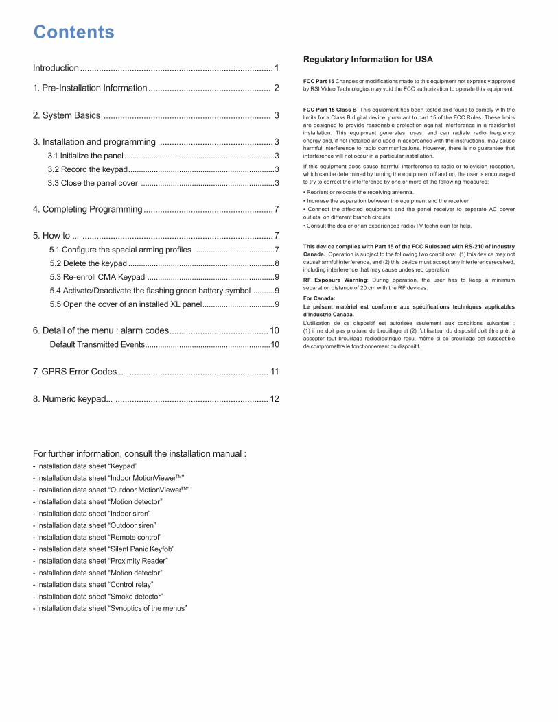
• Naming the 4 Logical AreasAreas are meant to show logical separation between devices. The feature is important for configuring entry and exit devices, and also for configuring the ‘Stay’ mode. Devices that are categorized in area number 1 will always be subject to the entry and exit delay. The table below shows a typical area configuration for a light commercial and residential installation.
Area Office Installation Area Resi Installation
1 ENTRY DELAY 1 ENTRY DELAY
2 FRONT OFFICE 2 LIVING ROOM
3 ACCOUNTING 3 UPPER LEVEL
4 WAREHOUSE 4 GARAGE
(Devices learned to Area 1 are subject to the entry and exit delay.)
• Naming DevicesPrepare names for the devices that will be enrolled to the system. The Videofied XL can be programmed with a complete logical name for each peripheral device up to 16 characters in length.
• Choose which area each device will be programmed to. Devices that are placed in Area 1 will behave with an entry and exit delay. Devices placed in any other area will provide an instant alarm trigger.
1. Pre-Installation Information
2. System Basics
1 Devices in Area 1 are always delayed.
2 Do not install the Videofied XL control panel on or near a high voltage electrical panel. This can cause interference resulting in poor performance of the radio and GPRS modem.
3 Use the to clear the previous character when in a parameter.
4 Devices can only be recorded once. A device must be deleted before being recorded again.
5 The system supports a maximum of 19 peripheral devices in any device type combination. A keypad will count as a peripheral device.
6 PIR and MotionViewers should be mounted 2m10 to 2m35 (7’ to 8’) high.
7 Outdoor MotionViewers should be mounted 2m to 3m (7.5’ to 9’) high. These devices should be mounted in a manner that terminates the view of the PIR, protecting an asset rather than an area..
8 Mount the remote keypad last as the device is useful to have mobile during the installation procedure.
Always clean the camera lens after installation (Use a clean dry piece of cloth. Take care not to apply pressure to the lens.).
10 Use the key to change case when typing on the keypad.
11 Use caution when opening and closing the panel cover as internal components are fragile.
• Choose which devices will be armed the ‘Stay’ mode.
• Retrieve code list to be programmed from end user (19 maximum access codes with 4 to 6 numbers per code).
9

003 Videofied Security System Instal lat ion Manual
The keypad display will time-out after 30 seconds of inactivity. Press ANY key to bring the display back.
13 The control panel, interior siren, and exterior siren use D-Cell alkaline batteries.
3. Installation and programming
2. System Basics
Open the box and remove the cardboard mounting template sitting on top. Place template on wall with arrow pointing upward. Mark the 5 screw points on the wall and drill pilot holes for wall anchors. Install wall anchors, then attach base of control panel to wall. A screw must be used in the tamper protection hole for the panel wall tamper to function correctly. Insert 8 D-Cell alkaline batteries in the battery trays. Make sure to note proper battery orientation. Before removing the front side of the packaging box, insert the SIM card (voice/data or GSM/GPRS) as illustrated in figures 1 and 2.
Connect the front side to the base by aligning the hinges on the base as seen above.
3.1 Initialize the panel
• Insert the power cable into the power connection (the panel emits a beep) and the keypad lights up and flashes.
• Hold down the PROGRAM BUTTON on the panel for 10 seconds until the keypad beeps again and lights up all the keys of the panel keypad.
• Press and release instantly the PROGRAM BUTTON of the panel again to switch to keypad registration mode.
3.2 Record the keypad (Ref. Keypad installation data sheet)
• Insert the 3 Lithium LS14500 batteries in the keypad.
• Do not mount the keypad.
• Simultaneously press the [CLR] and [ESC NO] buttons on the keypad, until the keypad’s LED flashes, then release.
3.3 Close the panel cover
• Tighten the screw on the left side of the control panel to secure the cover.
14 The ITRA110and DCVA200/700 (devices with pet immune) should never be placed in stairs, or near stairs. (Risk of false alarms).
15 When a Colon [:] appears you can modify the parameter.
12
Figure 1 Figure 2
BaseHinges
PROGRAM Button
Alkaline batteriesPower
connection
Power cable

4
Display of the keypad
3. Installation and programming
Actions and Descriptions
KEYPAD 1RECORDED
RADIO RANGETEST ?
RADIO RANGEx/9
RADIO RANGE9/9
RADIO RANGETEST ?
ENTER THEINSTALLER CODE
if you are going to monitor through a Central Monitoring Station. if you are not
4 TO 6 DIGITSTHEN YES
INSTALLER CODE :
CODE NAME :
ADJUSTINGTIME AND DATE
DATE (Year) :00/ /
CONNECTED TO MONITOR STATION?
Repeat for Month, Day, Time and Minutes.
Wait Use right or left arrows to modify the parameters and the [YES] key to save the value and move to the next.
Name the code +
Installer code + , then confirm : Code +
Wait
Wait
Wait for 30s in order to obtain the first stable value
Verify the range : A value of 5/9 or better indicates a sufficient RF radio.
Stop the radio range test.
< - LANGUAGE - >ENGLISH to select the language.

005Videofied Security System Instal lat ion Manual
to modify the value +
to modify the value +
Keypad Programming3. Installation and programming
Display of the keypad Actions and Descriptions
ACCOUNT NUMBER :
PERIODIC TEST
PERIODIC TEST :24 HOURS
TEST HOUR :00
Enter the account number issued by your central station +
CODE/STATEMODIFICATION ?
ENTERYOUR I.D. :
Wait
to keep default transmitted events or (to modify the event transmission status,and the on/off controls, refer to Chapter 6.Details on the alarm codes menu, page 10).
to increase hours + , and do the same for minutes.
to change the period +
NAME OR ADDRESS
NAME OR ADDRESSENTRY COMPLETE
AREA CONFIGURATION
AREA NAME 1 :
EXIT DELAY :45 sec
Enter the name of the logical area 1 + .
Repeat this step for areas 2,3,4. Refer to page 2 for more information.
Wait
Enter “name” or “address” + (Name of the client, informative and optional data only).
ENTRY DELAY :15 sec
GPRSPARAMETERS ?

6
3. Installation and programming
Display of the keypad Actions and Descriptions
GPRS parameters are provided by the cellular carrier. It is necessary to enter the correct information for the carrier you use.
Remark : GPRS Parameters are Case Sensitive ! (use the M/m key of the keypad to change between upper / lower case letters).
Be careful : Use arrows to change from one parameter to the other. Press on the [YES] key only when you want to modify a parameter!
(The APN code is provided by your cellular provider. These parameters will change with the SIM card used. Ask your cellular provider for additional information.)
Press [YES] to modify, a Domain name will only be used if an IP address is not supplied by your Central Monitoring Station
TEST IN PROGRESSEND = YES
Wait (this could last for 3 minutes) for the result of the test which can be : - a level between 2/5 and 5/5 - an error code (in this case, view the list of GPRS error code descriptions on page 11)
GPRS LEVEL Press the and wait for the reception level. Do not remove the SIM card during this test!
GPRS carrier parameters are entered in this section. The first parameter is the APN code. By default, the fields will be blank. Press [YES] to modify the value or the right arrow to move on to the next parameter.
T-Mobile Wyless AT&T ...................
APN wap.voicestream.com telargo.t-mobile.com wap.cingular ...................
USER blank blank [email protected] ...................
PASS blank blank cingular1 ...................
APN CODEPress [YES] and enter the Access Point Name + [YES] - Right Arrow to next parameter.
PASSWORD Press [YES] to modify or RIGHT ARROW to skip.
USERNAME Press [YES] to modify or RIGHT ARROW to skip.
IP 1 ADDRESS Press [YES] to modify, all preceding zeros of the octet must be entered. This information can only be retrieved by your central station.
DOMAIN NAME 1
Press [YES] to modify or RIGHT ARROW to skip if you are using the default 888PORT 1
Press [YES] to modify, all preceding zeros of the octet must be enteredTMT IP
Press [YES] to modify, a Domain name is only used if a IP address is not suppliedTMT DOMAIN NAME
Press [YES] to modify or RIGHT ARROW to skip if you are using the default 888.TMT PORT
SMTP GPRS, PAQUET SIZE, DATA TIMEOUT, and PACKET SIZE should all be kept at the default values.

007Videofied Security System Instal lat ion Manual
GPRS LEVEL5/5
Do not install the system in an area where GPRS reception is lower than 3/5.
PRESS PROGRAMBUTTON OF DEVICE
Press [YES] record your devices : (please refer to installation data sheets for each device).
4. Completing Programming
After all devices have been recorded and mounted the display will show :
5. How to...
Display of the keypad Actions and Descriptions
ENTERING A NEWDEVICE ?
OPERATIONCOMPLETED ?
SYSTEM CHECKIN PROGRESS
INSTALLATIONSUCCESSFUL !
(Close the cover of the panel)
All that remains is to program the user codes and special arming profiles.
Verify that the control panel is completely closed, and the screws are properly tightened.
5.1 Configure the Special Arming Profiles
With the direction arrows go to the menu
CONFIGURATION (LVL 4) -> ALARM MODES PROGRAMMABLE
Then use the direction arrows to select the relevant arming mode and the [YES] key to modify it.
There are three possible arming modes.
FULLY ARMED is the general arming mode, set using a badge or with a user code and keys or .
SP1 is a partial mode activated by entering a user code and pressing the . This mode is also accessible on a CMA keypad via the and via an RC remote control via the .
SP2 is not accessible on the keypad of an XL panel. It is available on a CMA keypad via the and via an RC remote control via the .
For each arming mode, it is possible to specify how each of the 4 areas will be armed and how the system will behave during an alarm.
Areas : 1 2 3 4 Each time you press the corresponding
number, the system will toggle the arming state
for the respective area.
State : A A A A Press the [YES] key after this configuration step. The system will then display which siren mode will be in effect for this special profile. Select the siren mode using the direction arrows then press [YES].
A Armed Siren Immediate triggering of all sirens
D DisarmedDelay beeps
Entry/Exit delay
beeps, then triggering
of the sirens
P Perimeter(all the opening contacts)
Silent Without siren without beeps
EExternal (opening
contacts protecting an exterior access)
Without siren
Beeps on the keypad only
Special Modes 1 and 2 prompt to rename the profile after selecting the siren mode. This prompt will display “DESIGNATION MODE:”. Use the keypad to enter a logical name or press the [YES] key with the field blank to store the default.
Display of the keypad Actions and Descriptions

00 8
5. How to ...
Display of the keypad Actions and Descriptions
ACCESS LEVELLEVEL : 3 => 4 Use the right arrow to change the access level to 4.
ACCESS LEVEL3
BADGE OR CODE Enter the installer code +
< = = = = XX = = = = > You can remove the device batteries.
DELETEKEYPAD
ACCESS LEVEL4
GENERALPARAMETERS
AREAS ANDDEVICES
DEVICES
Use the right arrow to go to the CONFIGURATION menu.
ADD A NEWDEVICE Right arrow to go to the DEVICE CONFIGURATION menu.
Press the left arrow twice to go to the AREAS AND DEVICES menu.
BADGE OR CODE Enter the installer code +
DEVICECONFIGURATION
A1:KEYPADKEYPAD 1 (If necessary, use the direction arrows to select the peripheral device).
5.2 Delete the keypad or any peripheral device
CONFIGURATION

00Videofied Security System Instal lat ion Manual9
5. How to ...
5.3 Reconnect a CMA keypad to an XL panel without opening the cover after initial programming has been completed.
Wave your hand over the XL keypad to activate the display. Press and hold the for three seconds to enter the programming mode. When you have successfully entered the programming mode the keypad display will flash. Type the code ‘000000’ then press .This will enable keypad registration mode. The numerical LED display will begin to dance.
Install the batteries in the CMA keypad. Simultaneously press and release the [CLR] and [ESC NO] buttons on the keypad. The red LED indicator light will blink rapidly, then twice slowly. The keypad display will change to KEYPAD 1 RECORDED. Press the [YES] key to acknowledge this, then type the installer code for the system followed by the [YES] button.
This keypad learning procedure is only used when connecting a CMA keypad to the XL control panel after initial programming. For initial system configuration refer to page 3.
It is possible to activate or deactivate the flashing green battery symbol.
Bear in mind that when this symbol is activated, the product has less battery life and the batteries will have to be changed within 4 years.
Enter in special mode by pressing for 3 seconds on the and the numerical keypad starts to flash.
Type the code 000100 then the digital keypad will remain illuminated while the green battery symbol starts to flash with the number 0 or 1 on the 7-segment digit.
The number shown is an indication of the display configuration for the battery symbol (0 for disactivated, 1 for activated).
5.4 Activate or deactivate the flashing green battery symbol
5.5 Opening the cover of an installed XL panel
Unscrew the screw on the left-hand side of the panel from the base on the hinges.
KEYPAD 1 RECORDED
INSTALLATION CODE Enter the installer code +
Display of the keypad Actions

10
6. Details of the menu : ALARM CODES
Default Transmitted Events
By default these events are transmited:
DEVICE (intrusions)ALERT (button)TAMPERPERIODIC TESTPANEL BATTERIESDEVICE BATTERIESSUPERVISION
By default are not transmited:
INITIALIZATION
AC POWER (AC power failure)
PHONELINE FAULT (line failure)
RADIO JAMMING (radio jamming)
WRONG CODES (when entering 5 incorrect codes/badges)
DURESS CODE
ALARM MEMO (Acknowledgement of alarm at keypad)
ARM/DISARM (open/close)There are the 3 transmission
states:
ALARM, event is transmitted upon occurence.
ALARM / END, event is transmit-ted on occurrence and on event restoral.NOT TRANSMITTED
Example:
If this system is configured at your central station for supervised openings and closings, the parameter ARM / DISARM must be changed from NOT TRANSMITTED to ALARM / END
Changing the transmission type for an event
Two Methods:
• During initial programming and after the prompt for PERIODIC TEST the keypad will display :
CODE/STATEMODIFICATION ?
• After initial installation with a CMA keypad :
Use the direction arrows to browse to CONFIGURATION (level 4) -> CONFIGURATION MONITOR. STATION -> ALARM CODES -> TRANS. STATE MODIFICATION
Then:
Use the direction arrows to find the event type to be modified. Press the to edit the item, then the direction arrows to choose the transmission option. Press the button to save the option.
Press to access the menu TRANS. STATE MODIFICATION
In all cases, be sure to check that the configuration of your XL system is suitable for your needs.

7. GPRS Error Codes
GPRS LEVEL :ERROR XXX
In case of GPRS error during initial programming, it is recommend to continue installation by recording detectors and devices, returing to the GPRS level test after initial configuration is complete.
Below is a list of error codes that may be listed in the event log or displayed during the GPRS level test.
Codes Errors03 ou 04 No network coverage or no SIM card inserted
010 SIM not inserted
011 Code PIN necessary -> The PIN code must be deactivated
012 PUK code necessary, SIM card blocked013 Default SIM card014 SIM card busy015 Error on SIM 016 Incorrect password
017 SIM PIN2 necessary -> The PIN code must be deactivated
018 SIM PUK2 necessary022 SIM not found030 No network coverage or SIM not active/provisioned
040 : 047 SIM card non inappropriate or blocked -> Unlock with PUK code
149 Authentification error -> Network problem or incorrect parameters (APN, USER, ...)
107 Service not activated-> SIM card unsuitable
868 Mhz Codes
SIM cards for use with Videofied control panels must have security features disabled. No prompt for SIM PIN code.
Codes Errors
043 Typographical error in the APN Code, username, password or a provisioning problem
003 SIM card not detected/not inserted132 SIM card not activated030 GPRS Level Test: No GPRS Signal; Event Log: No Error Found
915 MHz codes
11

00 12
EMEA SALES23, avenue du Général Leclerc92340 BOURG-LA-REINEFRANCEHot line : +33 (0)820 846 620Fax : +33 (0)3 90 20 66 36
© 2009 RSI Video Technologies Videofied® is a Registered Trademark of RSI Video Technologies. Specifications subject to change without notice.
www.videofied.com
North American Headquarters4455 White Bear Parkway, Suite 700White Bear Lake, MN 55110USAHot Line : 877-206-5800Fax : 651-762-4693
8. Numeric Keypad
Symbols Explanations
D • When the indicator light is green: indicates that all the batteries (panel + peripheral) are OK
• When the indicator light is red: indicates that there is a battery fault either on the panel or on a peripheral device (the device number will be indicated on the display)
P• During arming: signals the detection of a peripheral device in a zone not on a time setting
• Not armed: tamper fault detection (the Number will be indicated on the display)
Used in order to identify:
• Number of the peripheral device (0 for the panel and 1 to 19 for the peripheral devices) in the vent of tamper fault, intrusion, low battery, etc. Will also display ‘E’ if the panic button is pressed.
• Incorrect user code (‘C’ for wrong code)
Indicates that there has been an intrusion
Indicates any other fault (radio interference, ect.) also indicates panic alarm
Symbols Explanations
D Used to disarm the system (after entering the code)
P• Enables the ‘Stay’ mode (Special Mode 1) after entering the proper user code.
• Flashes when the system is armed in the ‘Stay’ mode (Special Mode 1)
• Fully arms system(after entering the code)
• Flashes when the system is fully armed
Fully arms system (after entering the code)
Symbols Explanations
D Key to be held down for 3 seconds to activate panic buttons
P Once it lights up, pressing this key will send a police call through to the monitoring station
Once it lights up, pressing this key will send an emergency call through to the operators
Once it lights up, pressing this key will send an emergency call through to the operators
This key allows you to cancel the activation of the panic buttons
Symbols Explanationsà D Keys for entering user codes
P Key for confirming code
Backspace / Delete Entry Key
Using the numeric keypad: to conserve the batteries, the numerical keypad automatically turns off after a few seconds of not being used. Before entering the code, you need to reactivate it. To do so, place your hand flat over the numeric keypad, it will light up and then you can use it.

Made by RSI VIDEO TECHNOLOGIES Nov. 2010
Installation data sheet
Security System Videofied® - XL GPRS
- Installation data sheet “Keypad”- Installation data sheet “Indoor MotionViewer” - Installation data sheet “Outdoor MotionViewer” - Installation data sheet “Motion detector”- Installation data sheet “Indoor siren” - Installation data sheet “Outdoor siren” - Installation data sheet “Remote control”
- Installation data sheet “Silent Panic Keyfob”- Installation data sheet “Proximity Reader”- Installation data sheet “Motion detector” - Installation data sheet “Control relay”- Installation data sheet “Smoke detector”- Installation data sheet “Synoptics of the menus”
XL GPRS means XL600GPRS for USA/Canada, XL700GPRS for Australia and XL200GPRS for Europe and rest of the world.
EMEA Hotline : +33 (0)820 846 620 / UK : 0871 951 / Espagne : +34 90 166 77 00USA Hotline : 877-206-5800

Recording of a keypadThe alarm panel must be put in "Recording device mode", and the keypad must display “PRESS PROGRAM BUTTON OF DEVICE”.
Insertthe3batteriesLithium LS14500 (the 3batteriesareinsertedinthesame direction) Presssimultaneouslyon[CLR]and [ESCNO]ofthekeypaduntiltheindicator ofthekeypadflashesandrelease (possibilityoftestingtheRFrange).
1. Arming and Disarming
Thekeypadbecomesinactiveafter30secondsofinactivity.Torevive thekeypadyoucanpressanykeyon thekeypad.Thebestbuttontopressisthe[YES]keybecauseitwillnottriggeranaction.
Arming Fully Armed Special Mode 1 or 2 Perimeter
KeysoftheKeypad
Code+ +or+Code+ ++Code+
Disarming Fully Armed Special Mode 1 or 2 Perimeter
KeysoftheKeypad
+Code+ +Code+ +Code+
Tochangefromonearmingmodetoanother,youhaveto tofullydisarmthesystem.
IndicatorLED
SpecialArmingMode1and
SpecialArmingMode2
Directionarrows
Capital/Smallletter
Panicbutton
ProgrammingButtons
Display:2lineswith16characters
Perimeter
1
2
CMA means CMA600 for USA/Canada, CMA700 for Australia/Singapore and CMA200 for Europe and rest of the world. www.videofied.com
I N S T A L L A T I O N D A T A S H E E T
Keypad CMA
Made by RSI VIDEO TECHNOLOGIES

2. Obtaining special characters
Key
1st press
2th press
3th press
4th press
5th press
6th press
7th press
8th press
9th press
10thpress
11thpress
1 “space” . , ‘ ? ! ; : # 1
0 - + = / ¥ _ < > ( ) 0
@ @ $ % & * #
> REM:TheotherkeysfunctionasinwritingSMSwitha cellularphone.
3. Initiating Panic Alerts
3.1 Red Button of the keypadPanicalert:immediatelytriggersonallsirens.
Keyordertoactivate/disactivatethefunction:
Withdirectionarrows go to menu:PROGRAMMABLE FEATURES -> PANIC BUTTON ENABLED. Validatewiththe[YES]key.Usedirectionarrowstomodifythestate.Validatewiththe[YES]key. Entertheinstallercodeifneedbe.
3.2 Silent Panic alert Onthekeypad:Codeunderconstraint(orunderthreat):Usercode+1,example:(2999->3000)
Ontheremotecontrol:Press2secondsonthekey(acquisitionbipfor2seconds)
3.3 Audible Panic AlertOnthekeypad:Codeunderconstraint(orunderthreat):Usercode+2,example:(2999->3001)
Ontheremotecontrol:Press2secondsonthekey(acquisitionbipfor2seconds)
Remark:Iftheredbuttonofthekeypadisdeactivated,thealertsoundontheremotecontrolwillnotfunction,butonthekeypadwillstilldisplaythatthepanichasbeenpressedandwillrequireacode+[YES].
4. I have a problem, what should I do?
4.1 My first keypad does not record on the panel
Have you pressed on the PROGRAMBUTTON of the panelbeforetryingtorecordonthekeypad?
4.2 Retrieve a keypad deleted by error
Removethekeypad'sbatteries. Press the PROGRAMBUTTON of the panel for one second(coverclosed),(theindicatorflashesonce).Putbackthebatteriesandinitializethekeypadbysimultaneouslypressingonthe[CLR]and[ESCNO]keyunitltheindicatorofthelatterflashesandthenrelease.Itwillthenrequireyoutoentertheinstallercode(dosoandvalidatewiththe[YES])key,thenthekeypadisrecovered.
4.3 How to fix a faulty keypad, without re-program-ming the site
PressonthePROGRAMBUTTONofthepanelforonesecond(coverclosed),theindicatorflashesonce. Putthebatteriesinthenewkeypad. Press the [CLR] and [ESC/NO] keys simultaneously unit itsindicatorflashesandthenrelease.Thekeypadrecords. Keyintheinstallercodeagainonthekeypad'sdemand. PossibilityoftestingRFradiorangeandoutofthismenuandthenewkeypadisoperational. Proceedincarryingoutinlimitedtimeof15secondsandrenewtheoperationifneedbe.
(Donot forget todelete the faultykeypadof theprogramming,otherwisetherewillbeaRFSupervisionofradioloss…)
5. Add a second keypad
It ispossible toaddseveralkeypadsonthesamesite.Duringthe recording of a new keypad, it is possible to allocate to ageographicalzoneotherthanzone1,but inthiscasethenewchosenzoneshallalsobedelayed.
CMA means CMA600 for USA/Canada, CMA700 for Australia/Singapore and CMA200 for Europe and rest of the world.
EMEA SALES23, avenue du Général Leclerc92340 BOURG-LA-REINEFRANCEHot line : +33 (0)820 846 620 / UK : 0871 951Fax : +33 (0)3 90 20 66 36
© 2009 RSI Video Technologies Videofied® is a Registered Trademark of RSI Video Technologies. Specifications subject to change without notice.
North American Headquarter4455 White Bear Parkway, Suite 700White Bear Lake, MN 55110USAHot line : 877-206-5800Fax : 651-762-4693
www.videofied.com
I N S T A L L A T I O N I N S T R U C T I O NKeypad CMA

Recording of the detectorThe alarm panel must be placed in “Recording device”, mode then and the keypad must display“PRESS PROGRAM BUTTON OF DEVICE”.
Insert the 3 Lithium batteries LS14500 (in the same direction).
Press the PROGRAM BUTTON of the detector, release as soon as the indicator flashes.
With the aid of the keypad, continue recording by running the Radio Range Test and allocating an area....
Always place the camera on an unobstructed angle.
I n d i c a t o r LED
INIT Button
> Possibility of testing the RF range.
> Possibility of testing the detection cover range.
* This indicator will no longer flash from then on except at opening or during a detection test.
3
Pet immune Installation height
DCV200 DCV600 DCV700
NONEFrom 2m10 (6 1/2’) to 2m30 (7 1/2’) to the
bottom of the camera
DCVA200 DCVA600 DCVA700
YES 18 KG (40lbs)Must imperatively be 2m10 (6 1/2’) to the
bottom of the camera
The detector must be fixed with a screw, one of which must be positioned in the tear-off zone
Infrared illuminators
for night vision.
Objective of the camera
Camera
1
2
EMEA SALES23, avenue du Général Leclerc92340 BOURG-LA-REINEFRANCEHot line : +33 (0)820 846 620 / UK : 0871 951Fax : +33 (0)3 90 20 66 36
© 2009 RSI Video Technologies Videofied® is a Registered Trademark of RSI Video Technologies. Specifications subject to change without notice.
North American Headquarter4455 White Bear Parkway, Suite 700White Bear Lake, MN 55110USAHot line : 877-206-5800Fax : 651-762-4693
www.videofied.com
DCV means DCV600 for USA/Canada, DCV700 for Australia/Singapore and DCV200 for Europe and rest of the world.
I N S T A L L A T I O N D A T A S H E E T
Indoor MotionViewer DCV
Made by RSI VIDEO TECHNOLOGIES
Installation height of the pet immune camera : 2m10 (6 1/2’) to the bottom of the camera

Extention 5 cm (2 1/2
inches)
The outdoor MotionViewer detector DCV250/DCV650/DCV750 is integrated with filters and analytical levels which enables it from untimely triggering on with the presence of small animals : rabbits, cats, birds.... However, dogs, foxes and wild boars can be detected.
It is highly recommended to use a camera head kit (no Kodak screw) or our MB100 camera kit to fix the camera, indeed, if you bore a hole in the lower stand of the camera, its waterproofness will be lost...
Composition of the MB100 kit - Base stand with screw cover.
- A camera head enabling a 360° orientation of the camera with a wing screw (or Allen screw supplied with its key).
- Two extension cords - 5 cm each. Camera fixing screw (diameter 6.35 mm - 20 threads per inch).
Clamping ring
Ball pivot 360°
BaseScrew cover for the base
Screw + Allen key Wing screw
Indicator LED
Camera
Infrared LED for night vision
Base
Clamping screw for camera
DCV means DCV650 for USA/Canada, DCV750 for Australia/Singapore and DCV250 for Europe and rest of the world.
I N S T A L L A T I O N D A T A S H E E T
Outdoor MotionViewer DCV
Made by RSI VIDEO TECHNOLOGIES
Installation height of the outdoor camera : 2m80 to 3m (9’ to 9 1/2’) to the bottom of the camera

> Protect assets and entry points not area
> Possibility of testing RF cover (minimum radio level at 5/5).
> Possibility of testing the detection cover range.
* This indicator will no longer flash from then on except at
I N S T A L L A T I O N D A T A S H E E TOutdoor MotionViewer DCV
Recording of the detectorThe alarm panel must be put in "Recording device mode", and the keypad must display“PRESS PROGRAM BUTTON OF DEVICE”.
Insert the 3 Lithium batteries LS14500 (in the same directions).
Press the PROGRAM BUTTON of the camera detector, release as soon as the indicator flashes.
Carefully place the block camera on its base and screw down the 4 clamping screws.
Fix the base of the ball and socket head on a desired height and place (while respecting fixing height.
Place the screw cover on top and screw down the ball pivot.
If need be, use extentions then screw them down to the camera detector on the top of the ball and socket head (or extentions) and screw down the ring of the ball and socket head in order guarantee adequate fixing.
Finally, direct the camera as required and tighten with wing screw or Allen screw (to be used instead of the wing screw).
Test the RF range (RSSI level at 20 seconds).
Allocate an area (with direction arrows of the keypad) and validate with the [YES] key.
Name the device.
Test the detection coverage area.
3
4
5
6
7
8
9
10
11
Location of the ball pivot, camera fixing screw
Self protection of the camera
Back wall
Camera block
Program Button
1
2
EMEA SALES23, avenue du Général Leclerc92340 BOURG-LA-REINEFRANCEHot line : +33 (0)820 846 620 / UK : 0871 951Fax : +33 (0)3 90 20 66 36
© 2009 RSI Video Technologies Videofied® is a Registered Trademark of RSI Video Technologies. Specifications subject to change without notice.
North American Headquarter4455 White Bear Parkway, Suite 700White Bear Lake, MN 55110USAHot line : 877-206-5800Fax : 651-762-4693
www.videofied.com
DCV means DCV650 for USA/Canada, DCV750 for Australia/Singapore and DCV250 for Europe and rest of the world.

Recording of the detectorThe alarm panel must be put in "Recording device mode", and the keypad must display“PRESS PROGRAM BUTTON OF DEVICE”.
Insert the Lithium LS14500 Battery.
Press on the PROGRAM button of the detector, release as soon as the indicator flashes.
With the aid of the keypad, continue recording by allocating an area name ...
Height of the pet animal detectors: must be 2m10 (6 1/2’) minimum.
Always place the camera on an unobstructed angle.
Indicator LED
PROGRAM Button
> Possibility of testing the RF range.
> Possibility of testing the detection cover range.
* This indicator will no longer flash from then on except at opening, arming or during a detection test.
3
Pet immune Installation height
ITR110 ITR600
NONEFrom 2m10 (6 1/2’) to
2m30 (7 1/2) to the bottom of the camera
ITRA110 ITRA600
YES 18 KG (40lbs)Must be 2m10 (6
1/2’) minimum to the bottom of the camera
The detector must be fixed
with a screw, one of which must be positioned in the
tear-off zone
1
2
EMEA SALES23, avenue du Général Leclerc92340 BOURG-LA-REINEFRANCEHot line : +33 (0)820 846 620 / UK : 0871 951Fax : +33 (0)3 90 20 66 36
© 2009 RSI Video Technologies Videofied® is a Registered Trademark of RSI Video Technologies. Specifications subject to change without notice.
North American Headquarter4455 White Bear Parkway, Suite 700White Bear Lake, MN 55110USAHot line : 877-206-5800Fax : 651-762-4693
www.videofied.com
ITR & ITRA means ITR600 & ITRA600 for USA/Canada and ITR110 & ITRA110 for Europe and rest of the world.
I N S T A L L A T I O N D A T A S H E E T
Movement detector ITR & ITRA
Made by RSI VIDEO TECHNOLOGIES
Installtion height of pet immune PIR: 2m10 (6 1/2’) to the bottom of the device

Recording the interior sirenThe alarm panel must be put in "Recording device mode", and the keypad must display“PRESS PROGRAM BUTTON OF DEVICE”.
Insert the 4 batteries Alkaline LR20.
Press carefully the PROGRAM Button of the siren, release as soon as the indicator flashes.
-> Possibility of testing the RF range.
Indicator LEDPROGRAMButton
Alkaline batteries
> Remark : The addition of an interior siren will inhibite the panel siren, which can be reactivated.
To do this then go to the menu : CONFIGURATION -> AREAS AND DEVICES-> SIREN PANEL + [YES].
Chose the authorized state.
> Remark : When a interior siren is added, the entry/exit beeps are automatically added into it.
It is possible to remove it in the menu : CONFIGURATION -> AREAS AND DEVICES -> DELAY BEEPS + [YES].
Chose the inhibited state.
1
2
EMEA SALES23, avenue du Général Leclerc92340 BOURG-LA-REINEFRANCEHot line : +33 (0)820 846 620 / UK : 0871 951Fax : +33 (0)3 90 20 66 36
© 2009 RSI Video Technologies Videofied® is a Registered Trademark of RSI Video Technologies.Specifications subject to change without notice.
North American Headquarter4455 White Bear Parkway, Suite 700White Bear Lake, MN 55110USAHot line : 877-206-5800Fax : 651-762-4693
www.videofied.com
SE means SE600 for USA/Canada, SE700 for Australia/Singapore and SE200 for Europe and rest of the world.
I N S T A L L A T I O N D A T A S H E E T
Indoor Siren SE
Made by RSI VIDEO TECHNOLOGIES
USE ALKALINE BATTERIES ONLY

Recording of the exterior siren The alarm panel must be put in "Recording device mode", and the keypad must display“PRESS PROGRAM BUTTON OF DEVICE”.
Insert the 4 batteries Alkaline LR20.
Press carefully the PROGRAM Button of the siren, release as soon as the indicator flashes.
To the question REMOTE CONTROLLED, answer : [ESC/NO].
-> Possibility of testing the RF range.
Indicator LEDPROGRAM Button
Alkaline batteries
Reminder : Outdoor siren : waterproof : IP432.
3
Do not forget to connect the strobe's cable !!!
Strobe positioned downwards
1
2
EMEA SALES23, avenue du Général Leclerc92340 BOURG-LA-REINEFRANCEHot line : +33 (0)820 846 620 / UK : 0871 951Fax : +33 (0)3 90 20 66 36
© 2009 RSI Video Technologies Videofied® is a Registered Trademark of RSI Video Technologies. Specifications subject to change without notice.
North American Headquarter4455 White Bear Parkway, Suite 700White Bear Lake, MN 55110USAHot line : 877-206-5800Fax : 651-762-4693
www.videofied.com
I N S T A L L A T I O N D A T A S H E E T
Outdoor siren SE
Made by RSI VIDEO TECHNOLOGIES
ALKALINE BATTERIES ONLYThe siren must be positioned downwards.
SE means SE650 for USA/Canada, SE750 for Australia/Singapore and SE250 for Europe and rest of the world.
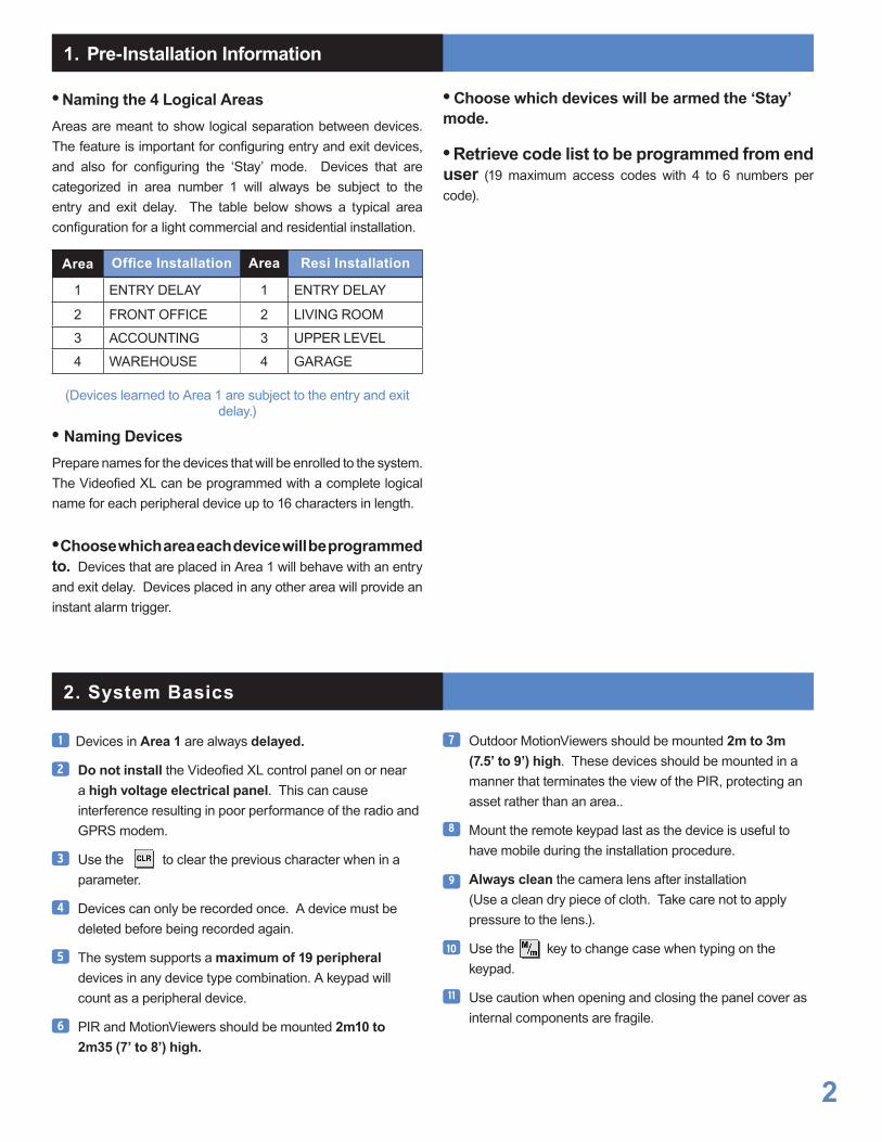
Recording of the remote controlThe alarm panel must be put in "Recording device mode", and the keypad must display“PRESS PROGRAM BUTTON OF DEVICE”.
Press 5 seconds simultaneously on the ON and OFF keys of the remote control.
When released the remote control emits bips and then records.
If the remote control does not record, first verify if the keypad displays well :
then simultaneously press once more on the ON and OFF of the remote control for 5 seconds (by firmly pressing on the keys). If the remote control does not record then carry out the operation once again but this time for 12 seconds.
PRESS PROGRAMBUTTON OF DEVICE
Press simultaneously for 5 seconds
ON and OFF
> Fonctioning
During the arming (Full and Special modes) and disarmings, it is necessary to press on the desired key and release very quickly with the first beep. Do not press and hold on the key ! On the other hand, if the desired control is accepted by the panel, the remote control will emit 2 beeps otherwise one and you will have to retry ... For alerts (long pressing for 2 seconds on the partials), from the begining of the pressing the remote control emits a beep, then again at the end 2 seconds indicating that the duration of pressure is sufficient, you can then release the key. If the panel recieved the frame of alert, the remote control emits 2 beeps, indicating a good functioning condition. Otherwise the remote control will only emit one sound, then renew the operation.
> Remark : This remote control has only one battery (lithium) solded with an autonomy and a standard use of 10 years. Do not try to open the remote control.
Reminder of the controls
Full Arming
Special Mode 1
Audible Panic Alert
by pressing 2 seconds
Disarming
Special Mode 2
Silent panic alert by
pressing 2 seconds
According to the version of the Videofied panel, if we use the remote control to arm the system, it transfers the time out beeps (which will enable you to know if the contact of the site remained open : 4 seconds long beep on the remote control, if everything is ok, the remote control transfers the beeps normally). It is not necessary to wait for the end of the beep to leave the site (for example, if arming is carried out from a car, the beeps will automatically stop at the end of 45 seconds).
EMEA SALES23, avenue du Général Leclerc92340 BOURG-LA-REINEFRANCEHot line : +33 (0)820 846 620 / UK : 0871 951Fax : +33 (0)3 90 20 66 36
© 2009 RSI Video Technologies Videofied® is a Registered Trademark of RSI Video Technologies. Specifications subject to change without notice.
North American Headquarter4455 White Bear Parkway, Suite 700White Bear Lake, MN 55110USAHot line : 877-206-5800Fax : 651-762-4693
www.videofied.com
I N S T A L L A T I O N D A T A S H E E T
4 buttons remote controlRC
Made by RSI VIDEO TECHNOLOGIES
RC means RC600 for USA/Canada, RC700 for Australia/Singapore and RC200 for Europe and
rest of the world.

Recording of the proximity readerThe alarm panel must be put in "Recording device mode", and the keypad must display“PRESS PROGRAM BUTTON OF DEVICE”.
Fixthebasewithmarks«TOP-HIGH»,upwards. Fixthescrewunderthebasematterpart,so thatthearmingtobeoperational.
Insert,thefirst(lithium battery LS14500),waitfor2beepsofthereadertheninsertthe 2otherbatteries(in the same direction).
PressthePROGRAMButton,releaseassoonasthe indicatorflashes.
Allocateazone(withthekeypaddirectionarrows), validationbythetouch[YES].
Giveitanameandvalidatewiththe[YES]key.
Mocate“TOP-HIGH”
2screwsforfixing
Description
The proximity reader can be placed in the interior or exteriorbecausetheelectroniccardisweatherproof.ThisdeviceisusedforarminganddisarmingaVIDEOFIED®system.Therecordingofthebadgereaderinarecordingareamakesthatareaandalldevicesinthatareasubjecttotheentryandexitdelays.
Characteristics
Itispossibletorecord19badges,eachbadgetakesthepositionofausercode.Example:5badgesrecorded+4keypadusercodes,remaining10codesand/orbadgesavailable.
Inordertoreadthebadge,thebadgemustbeplacedincontactwiththereadersurfaceforapproximatelyhalfasecond(abeepisemittedwhenthebadgeisread).
Remark:Thetotalstartingupandstoppingarehandledbythebadgereaders...
Magnetfortamperopenon
thereader
Walltamperpunchout
Base to be fixed
PROGRAMButton
Surfaceofthebadgereader
Fixingpointoftheprotectionagainstopeningandpullingout
1
2
3
4
5
IndicatorLED
BR means BR650 for USA/Canada, BR750 for Australia/Singapore and BR250 for Europe and rest of the world.
www.videofied.com
I N S T A L L A T I O N D A T A S H E E T
Proximity Reader BR
Made by RSI VIDEO TECHNOLOGIES
Therecordingofthebadgereaderinageographicalrecordingareatemporizesthelatter.
1

Actions and commentaries
Recording a new badge
Withthekeypad,gotothemenu:
Display of the keypad Actions and commentaries
BADGESACCESCODES
BADGEORCODE
ENTERABADGE/CODE
BADGEORCODE
BADGENAME Namethisbadge+
Keyinyour(InstallerorUserlevel3)code
Placeyourbadgeonthereaderuntilyouheartwobeepsthenafterafewsecondsthedisplaywillchange
Thenrepeattheoperationforotherbadgesorpresson[ESC]for5secondstoreturntotheinitialmenu.
Delete a code
Withthekeypad,gotothemenu:
Display of the keypad
ENTERABADGE/CODE
DELETINGBADGES/CODES
DELETINGCODEACCESS5
BADGEDELETED
toacceptthedeletion
Thenrepeattheoperationforotherbadgesorpresson[ESC]for5secondstoreturntotheinitialmenu.
Then tochosetheconcernedbadge toselectthebadge.
BR means BR650 for USA/Canada, BR750 for Australia/Singapore and BR250 for Europe and rest of the world.
www.videofied.com
I N S T A L L A T I O N D A T A S H E E TProximity Reader BR

Reminder:
LEVEL 1 =Arming,disarmingandpartials.
LEVEL 2 and 3 =LEVEL1
+Readingeventlogs
+Changingdateandtime
+Checkofthecorrectfunctioningofthe system
BR means BR650 for USA/Canada, BR750 for Australia/Singapore and BR250 for Europe and rest of the world.
Actions and commentaries
Modify the level of a code (Requires a level 3 code)
Withthekeypad,gotothemenu:
Display of the keypad
ENTERABADGE/CODE
BADGE/CODECONFIGURATION
Thetochosethecocernedbadgeand toselectthebadge.
MODIFYNAMEBADGE/CODES
www.videofied.com
I N S T A L L A T I O N D A T A S H E E TProximity Reader BR
Then asmanytimesaspossibletoselecttherequiredlevel.
LEVELACCESS3
Thenfor5secondstoreturntotheinitialaumenu.
3
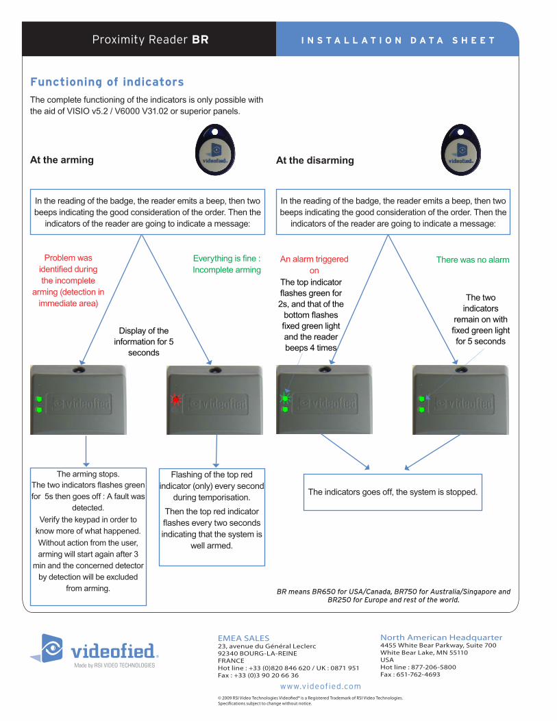
Functioning of indicators
ThecompletefunctioningoftheindicatorsisonlypossiblewiththeaidofVISIOv5.2/V6000V31.02orsuperiorpanels.
At the arming
Thearmingstops.Thetwoindicatorsflashesgreenfor5sthengoesoff:Afaultwas
detected.Verifythekeypadinordertoknowmoreofwhathappened.Withoutactionfromtheuser,armingwillstartagainafter3
minandtheconcerneddetectorbydetectionwillbeexcluded
fromarming.
Flashingofthetopredindicator(only)everysecond
duringtemporisation.Thenthetopredindicatorflasheseverytwosecondsindicatingthatthesystemis
wellarmed.
Everythingisfine:Incompletearming
Problemwasidentifiedduringtheincomplete
arming(detectioninimmediatearea)
Displayoftheinformationfor5
seconds
At the disarming
Theindicatorsgoesoff,thesystemisstopped.
TherewasnoalarmAnalarmtriggeredon
Thetopindicatorflashesgreenfor2s,andthatofthebottomflashesfixedgreenlightandthereaderbeeps4times
Thetwoindicators
remainonwithfixedgreenlightfor5seconds
Inthereadingofthebadge,thereaderemitsabeep,thentwobeepsindicatingthegoodconsiderationoftheorder.Thenthe
indicatorsofthereaderaregoingtoindicateamessage:
Inthereadingofthebadge,thereaderemitsabeep,thentwobeepsindicatingthegoodconsiderationoftheorder.Thenthe
indicatorsofthereaderaregoingtoindicateamessage:
EMEA SALES23, avenue du Général Leclerc92340 BOURG-LA-REINEFRANCEHot line : +33 (0)820 846 620 / UK : 0871 951Fax : +33 (0)3 90 20 66 36
© 2009 RSI Video Technologies Videofied® is a Registered Trademark of RSI Video Technologies. Specifications subject to change without notice.
North American Headquarter4455 White Bear Parkway, Suite 700White Bear Lake, MN 55110USAHot line : 877-206-5800Fax : 651-762-4693
www.videofied.com
I N S T A L L A T I O N D A T A S H E E TProximity Reader BR
BR means BR650 for USA/Canada, BR750 for Australia/Singapore and BR250 for Europe and rest of the world.

Mode EXT Jumper
INT : (Contact only)
EXT : (Wire entry only)INT + EXT : (Both)
---
---
Recording of the opening detectorAlarm panel has to be placed in “Recording device” mode, then the keypad must display“PRESS PROGRAM BUTTON OF DEVICE”.
Insert Lithium LS14500 battery.
Press PROGRAM Button of the contact and release as soon as the indicator flashes.
Allocate an area (with direction arrows of the keypad) of the keypad and validate with the [YES] key.
Protect an exterior access? Answer YES or NO (see the remark opposite).* This indicator will no longer flash from then on except at opening, arming
IndicatorLED
The markers must be lined up
Magnet + wedges
3
> For the magnet to have a better opening tolerance, must be positioned on the high part of the contact facing the the ILS, use the supplied wedge (see the diagram opposite).> Magnet should alway be positioned on the mobile part -> Possibility of testing the RF radio range. -> Possibility of testing opening detection.
Theconnector technology of the entry wire
Remark : The EXT black column points represent the position of 2 entry wires. Possibility of connecting a normally open/closed switch such as a swerved pivot, an infrared barrier, a smoke detector etc... These devices must be wired and in their normal state to the appropriate input before the door contact is learned in. The wire run to external devices can be no longer than 50’ with 18 gauge wire.
4
+ BATT -
Remark : Only recorded contacts as those protecting the external access will be concerned by the arming boundry. Use the keypad to activate this boundry: press on (to activate the keypad), then show
on the keypad enter a user code
and validate with the key
PERIMETER ARMING> BADGE OR CODE
Side view
1 cm maxiMagnet
Wedges
ILS
Contact
CT means : > CT600 (white) / CT610 (brown) for USA/Canada > CT700 (white) / CT710 (brown) for Australia/Singapore > CT201 (white) / CT211 (brown) for Europe and rest of the world.
PROGRAM Button
1 cm max.
1
2
EMEA SALES23, avenue du Général Leclerc92340 BOURG-LA-REINEFRANCEHot line : +33 (0)820 846 620 / UK : 0871 951Fax : +33 (0)3 90 20 66 36
© 2009 RSI Video Technologies Videofied® is a Registered Trademark of RSI Video Technologies. Specifications subject to change without notice.
North American Headquarter4455 White Bear Parkway, Suite 700White Bear Lake, MN 55110USAHot line : 877-206-5800Fax : 651-762-4693
www.videofied.com
I N S T A L L A T I O N D A T A S H E E T
DoorContactCT201/CT211/CT600/CT610/CT700/CT710
MadebyRSIVIDEOTECHNOLOGIES

Recording of the remote control relays of an action (tele reactivity)
The alarm center must be put in Recording device mode, and the keypad must display “PRESS PROGRAM BUTTON OF DEVICE.
Insertthe4batteriesAlkaline LR20.
PresscarefullyonthePROGRAMButtonoftherelay, releaseassoonastheindicatorflashes.
IndicateSiren1isrecorded,validatewith[YES].
PossibilityoftestingtheRFradiorange.
TothequestionREMOTE CONTROL,answer : YES or NO:Cf. Explanation of its functioning.IndicatorLED
PROGRAMButton
Alkalinebatteries
5
>IfyouanswerNO tothequestion:Remote control ? therelaywillbecountedlikeasirenSE550/SE650/SE750andautomaticallyactivateitsalarmrelayduringthedurationofthesiren.Themostusedapplicationinthistypeoffunctioningisthetriggeringoffalightfollowinganalarm...
>IfyouanswerYEStothequestion:Remote control? onalarm,theoperatorof thePCmonitoringstationhasthepossibility totriggerthecontrollingrelayfromdistance.
See the following example : Connection of the remote control of the relay (example of a smoke candle).
>TheRAR100isgoingtofunctionlikeaswitch. Itisgoingtotriggeronarelay(remotecontrolbyaPCmonitorstation following an alarm), closing a current circuit, therebytriggeringonthesmokecandle.
Theremotecontrolwillonlyworkfromapanel inversion3.0.I(andpreviousversions).
RAR 100
RCTAP
Relay
LinkSmokecandle
Voltmeter Battery
Inred:useaftertests
Ingreen:Fortests
Remark:Fortests,replacethesmokecandleswithavoltmeter[greenarrows(dotted)inplaceofofredarrows(straightlines)].Itwillthenbeeasytoseethetriggeringresult.(Wewillchangefrom0Volttothebatteryvoltage).
1
2
3
4
EMEA SALES23, avenue du Général Leclerc92340 BOURG-LA-REINEFRANCEHot line : +33 (0)820 846 620 / UK : 0871 951Fax : +33 (0)3 90 20 66 36
© 2009 RSI Video Technologies Videofied® is a Registered Trademark of RSI Video Technologies. Specifications subject to change without notice.
North American Headquarter4455 White Bear Parkway, Suite 700White Bear Lake, MN 55110USAHot line : 877-206-5800Fax : 651-762-4693
www.videofied.com
I N S T A L L A T I O N D A T A S H E E T
RemotecontrolrelayRAR
MadebyRSIVIDEOTECHNOLOGIES
RAR means RAR110 for Europe and rest of the world.

General Information Before installing detectors, please thoroughly read these installation instructions and NFPA 72, which provides detailed information on detector spacing, placement, zoning, wiring, and special applications.
NOTICE : This manual should be left with the owner/user of this equipment.
IMPORTANT : This detector must be tested and maintained regularly following NFPA 72 requirements. The detector should be cleaned at least once a year.
General Description
The SD photoelectronic smoke detector with built-in wireless transmitter is intended for use with wireless Videofied alarm systems that support SD series devices. Refer to alarm panel installation instructions for compatibility.
The SD smoke detector can be used for residential installations.
The transmitter can send alarm, and battery condition messages to the alarm panel. Refer to the alarm panel’s instructions for the maximum number of transmitters that can be supported.
The SD incorporates a state-of-the-art optical sensing chamber and an advanced microprocessor. The microprocessor allows the detector to automatically maintain proper operation at factory calibrated detection levels, even when sensitivity is altered due to the presence of contaminants settling into the unit’s smoke chamber.
In order for this feature to work properly, the chamber must never be opened while power is applied to the smoke detector. This includes cleaning, maintenance or screen replacement.
The SD contains a piezoelectric horn which generates the ANSI S3.41 temporal pattern in an alarm condition.
During an alarm condition, pressing the detector’s test switch will silence the piezoelectric horn for 5 minutes. Once the detector has reset, a message is transmitted to the control panel.
The built-in Drift Compensation algorithm automatically maintains the sensitivity of the detector.
The mounting base installation is simplified by the incorporation of features compatible with drywall fasteners or other methods that provide a method for securing the detector in place.
Two LEDs and a sounder on the detector provide local visual and audible indication of the detector’s status :
SD means SD600 for USA/Canada and SD200 for Europe and rest of the world.
1www.videofied.com
I N S T A L L A T I O N D A T A S H E E T
Smoke Detector SD
Made by RSI VIDEO TECHNOLOGIES

During initial power-up, the red and green LEDs will blink synchronously once every 5 seconds. It will take approximately 20 seconds for the detector to finish the power-up cycle (see Table 1).
Green LED Red LED Piezoelectric Horn
Power-up Blinks every 5 sec Blinks every 5 sec Off
Normal (standby) Blinks every 10 sec Off Off
Out of sensitivity Off Blinks every 5 sec Off
Smoke Alarm Off Blinks every 1 sec Temporal Pattern
Low Battery Off Blinks every 45 sec Chirp every 45 sec
After power-up has completed and the detector is functioning normally within its listed sensitivity range, the green LED blinks once every 10 seconds. If the detector is in need of maintenance because its sensitivity has shifted outside the listed limits, the red LED blinks once every 5 seconds.
When alarm has been activated by smoke, the red LED blinks every 1 second. The LED indication must not be used in place of the tests specified under Testing.
If the detector senses a low battery condition, the red LED blinks once every 45 seconds.
Low Battery Detection
The SD is powered by a single 3-volt CR123A or DL123A Lithium battery (included). The detector checks for a low battery at least every 65 minutes. If a low battery is detected, the transmitter sends a low battery message to the control panel, which displays a low battery message and forward it to the monitoring station.
In addition, the red LED of the SD will blink and the horn will chirp every 45 seconds and the test switch alarm function will be disabled. Pressing the test switch during this time will silence the chirps for 12 hours. The battery should be replaced BEFORE the chirps begin. Be sure to replace the battery with a fresh one.
Battery Installation and Replacement
To replace the battery:
1. Remove the detector from its mounting base by twisting the detector counterclockwise. Remove the battery, and dispose properly.
2. To ensure proper power-down sequence, wait a minimum of 20 seconds before installing new battery.
3. Install a new approved 3-volt Lithium battery in the battery compartment. Follow the polarity diagram inside the compartment.
4. Reinstall the smoke detector onto the mounting base by turning the detector clockwise.
5. The green LED should blink about once every 10 seconds to indicate normal operation. If the battery is not installed correctly, the smoke detector will not operate and the battery may be damaged. If the detector does not appear to be sending a signal during any of the tests, check for correct battery installation and for a fully charged battery.
Programming
The smoke detector must be enrolled in the control panel before it can operate in the system.
Table 1: Detector LED Modes
Recording of the detectorThe alarm panel must be put in "Recording device mode", and the keypad must display “PRESS PROGRAM BUTTON OF DEVICE”.
Insert the CR123 lithium battery.
Press the TEST SWITCH of the detector and wait feedback on the keypad.
With the aid of the keypad, continue recording by running the Radio Range Test
> Possibility of testing the RF range.
1
2
3
I N S T A L L A T I O N I N S T R U C T I O NSmoke Detector SD
SD means SD600 for USA/Canada and SD200 for Europe and rest of the world.

Mounting
Determine the best location for the smoke detector, one that provides a strong wireless transmission path and proper smoke detection. A good transmission path must be established from the proposed mounting location before permanently installing the detector.
To check, perform the RANGE TEST.
To mount the detector, perform the following steps:
1. Once a suitable location has been determined, install the mounting base on the ceiling or on the wall (if local
ordinances permit). Use the two screws and anchors provided.
2. Turn the detector in a clockwise direction in the mounting base until it clicks into place.
3. Test the detector immediately after completing the installation (as described in the TESTING section of this manual) and perform the RANGE TEST with the control system.
Figure 2. Detector Mounting Base
Figure 3. Mount Detector Across Ceiling Panel Support
DO NOT attach the detector to removable ceiling panels. Attach the detector across panel support as shown in Figure 3.
Dust covers are an effective way to limit the entry of dust into the smoke detector sensing chamber during construction. However, they may not completely prevent airborne dust particles from entering the detector. Therefore, it is recommended that the detectors be removed before beginning construction or other dust producing activity. When returning the system to service, be sure to remove the dust covers from any detectors that were left in place during construction.
Smoke detectors are not to be used with detector guards unless the combination has been evaluated and found suitable for that purpose.
I N S T A L L A T I O N I N S T R U C T I O NSmoke Detector SD
SD means SD600 for USA/Canada and SD200 for Europe and rest of the world.
3www.videofied.com

Testing the Sensor
NOTE : Before testing, notify the central station that the smoke detector system is undergoing maintenance, in order to prevent unwanted alarms.
Detectors must be tested after installation and following periodic maintenance. The SD may be tested as follows:
A. Test Switch1. A recessed test switch is located on the detector housing.
2. Push and hold the recessed test switch for a minimum of 5 seconds. Use a small screwdriver or Allen key with maximum diameter of 0.18 inch (the alarm panel will trigger and then the smoke detector will go into alarm. If the tool is removed from the recessed switch the sounder will shut off.)
If the detector is within the listed sensitivity limits, the LED on the detector should blink once per second and the horn should sound within 3 seconds.
B. Smoke Entry TestHold a smoldering punk stick or cotton wick at the side of the detector and gently blow smoke through the detector until the unit alarms. Canned aerosol is also an acceptable method.
Testing Signal Strength
NOTE : Remove battery tab before installation.
A test should be performed before installation to determine a strong communication path with the control panel and after installation is complete. Also, the owner/user should test the unit at least weekly.
Maintenance
NOTE : Before performing maintenance on the detector, notify the proper authorities and the central station that maintenance is being performed and the system will be temporarily out of service.
Disable the zone or system undergoing maintenance to prevent any unwanted alarms.
Power must be removed from the detector before performing maintenance of any kind by removing the detector’s battery.
1. To ensure proper power-down sequence, battery must be removed from detector for a minimum of 20 seconds before removing chamber top.
2. Remove the detector cover by turning counterclockwise.
3. Vacuum the cover or use canned air to remove any dust or debris.
4. Remove the top half of the screen/sensing chamber by lifting straight up (Figure 5).
5. Vacuum or use canned air to remove any dust or particles that are present on all chamber sections.
6. Replace the top half of the screen/sensing chamber by aligning the arrow on the screen/sensing chamber with the arrow on the housing. Press down firmly until the screen/sensing chamber is fully seated.
7. Replace the detector cover by placing it over the screen/ sensing chamber and turning it clockwise until it snaps into place.
8. Reinstall the battery into the battery compartment noting proper orientation.
9. Reinstall the detector and test. (See the Testing section.)
10. Notify the central station when the system is back in service.
Specifications
Power Source: One 3-volt CR123A Lithium Batteries (included). (Replace with Duracell DL123A, Panasonic CR123A) Height: 2.3 inches (58 mm) Diameter: 5.3 inches (135 mm) with mounting base Weight: 8.5 oz. (241 g) without battery Operating Ambient Temperature Range: 32° to 100°F (0° to 38°C) Operating Humidity Range: 0% to 95% Relative Humidity Agency Listings: UL 217 –Residential Installations
FOR WARRANTY INFORMATION AND FOR DETAILS REGARDING THE LIMITATIONS OF THE ENTIRE ALARM SYSTEM, REFER TO THE INSTALLATION INSTRUCTIONS FOR THE RECEIVER/CONTROL WITH WHICH THIS DEVICE IS USED.
Figure 5. Removing
Screen/sensing Chamber
I N S T A L L A T I O N I N S T R U C T I O NSmoke Detector SD

Limitations of Fire Alarm Systems
Manufacturer recommends that smoke and/or heat detectors be located throughout a protected premise following the recommendations of the current edition of the National Fire Protection Association Standard 72, National Fire Alarm Code (NFPA 72), manufacturer’s recommendations, state and local codes, and the recommendations contained in Guide for the Proper Use of System Smoke Detectors, which is made available at no charge to all installing dealers. A study by the Federal Emergency Management Agency (an agency of the United States government) indicated that smoke detectors may not go off or give early warning in as many as 35% of all fires. While fire alarm systems are designed to provide warning against fire, they do not guarantee warning or protection against fire. Any alarm system is subject to compromise or failure to warn for a variety of reasons. For example:
• Particles of combustion or “smoke” from a developing fire may not reach the sensing chambers of the smoke detector because: - Barriers such as closed or partially closed doors, walls, or chimneys may inhibit flow. - Smoke particles may become “cold” and stratify, and may not reach the ceiling or upper walls where detectors are located. - Smoke particles may be blown away from detectors by air outlets. - Smoke particles may be drawn into air returns before reaching the detector.
In general, smoke detectors on one level of a structure cannot be expected to sense fires developing on another level.
• The amount of “smoke” present may be insufficient to alarm smoke detectors. Smoke detectors are designed to alarm at various levels of smoke density. If such density levels are not created by a developing fire at the location of detectors, the detectors will not go into alarm.
• Smoke detectors, even when working properly, have sensing limitations. Detectors that have photoelectronic sensing chambers tend to detect smoldering fires better than flaming fires, which have little visible smoke. Detectors that have ionizing-type sensing chambers tend to detect fast flaming fires better than smoldering fires. Because fires develop in different ways and are often unpredictable in their growth, neither type of detector is necessarily best and a given type of detector may not provide adequate warning of a fire.
• Smoke detectors are subject to false alarms and nuisance alarms. For example, a smoke detector located in or near a kitchen may go into nuisance alarm during normal operation of kitchen appliances. In addition, dusty or steamy environments may cause a smoke detector to falsely alarm. If the location of a smoke detector causes an abundance of false alarms or nuisance alarms, do not disconnect the smoke detector; call a professional to analyze the situation and recommend a solution.
• Smoke detectors cannot be expected to provide adequate warning of fires caused by arson, children playing with matches (especially within bedrooms), smoking in bed, violent explosions (caused by escaping gas, improper storage of flammable materials, etc.).
• Heat detectors do not sense particles of combustion and are designed to alarm only when heat on their sensors increase at a predetermined rate or reaches a predetermined level. Heat detectors are designed to protect property, not life.
• Warning devices (including horns, sirens, and bells) may not alert people or wake up sleepers who are located on the other side of closed or partially open doors. A warning device that activates on a different floor or level of a dwelling or structure is less likely to awaken or alert people. Even persons who are awake may not notice the warning if the alarm is muffled by noise from a stereo, radio, air conditioner or other appliance, or by passing traffic. Audible warning devices may not alert the hearing-impaired (strobes or other devices should be provided to warn these people). Any warning device may fail to alert people with a disability, deep sleepers, people who have recently used alcohol or drugs, or people on medication or sleeping pills.
- Please note that: i) Strobes can, under certain circumstances, cause seizures in people with conditions such as epilepsy. ii) Studies have shown that certain people, even when they hear a fire alarm signal, do not respond or comprehend the meaning of the signal. It is the property owner’s responsibility to conduct fire drills and other training exercises to make people aware of fire alarm signals and instruct on the proper reaction to alarm signals. iii) In rare instances, the sounding of a warning device can cause temporary or permanent hearing loss.
• Telephone lines needed to transmit alarm signals from a premises to a central station may be out of service or temporarily out of service. For added protection against telephone line failure, backup radio transmission systems are recommended.
• System components, though designed to last many years, can fail at any time. As a precautionary measure, it is recommended that smoke detectors be checked, maintained, and replaced per manufacturer’s recommendations.
• System components will not work without electrical power. If system batteries are not serviced or replaced regularly, they may not provide battery backup when AC power fails.
• Environments with high air velocity or that are dusty or dirty require more frequent maintenance.
In general, fire alarm systems and devices will not work without power and will not function properly unless they are maintained and tested regularly. While installing a fire alarm system may make the owner eligible for a lower insurance rate, an alarm system is not a substitute for insurance. Property owners should continue to act prudently in protecting the premises and the people in the premises and should properly insure life and property and buy sufficient amounts of liability insurance to meet their needs.
I N S T A L L A T I O N I N S T R U C T I O NSmoke Detector SD
5

Requirements and recommendations for proper use of fire alarm systems including smoke detectors and other fire alarm devices: Early fire detection is best achieved by the installation and maintenance of fire detection equipment in all rooms and areas of the house or building in accordance with the requirements and recommendations of the current edition of the National Fire Protection Association Standard 72, National Fire Alarm Code (NFPA 72), the manufacturer’s recommendations, State and local codes and the recommendations contained in Guide for the Proper Use of System Smoke Detectors, which is made available at no charge to all installing dealers. For specific requirements, check with the local Authority Having Jurisdiction (ex. Fire Chief) for fire protection systems.
Requirements and Recommendations include: • For residential applications, smoke detectors shall be installed outside of each separate sleeping area in the immediate vicinity of the bedrooms and on each additional story of the family living unit, including basements and excluding crawl spaces and unfinished attics.
• Smoke detectors shall be installed in sleeping rooms in new construction and it is recommended that they shall also be installed in sleeping rooms in existing construction.
• It is recommended that more than one smoke detector shall be installed in a hallway if it is more than 30 feet long.
• It is recommended that there shall never be less then two smoke detectors per apartment or residence.
• It is recommended that smoke detectors be located in any room where an alarm control is located, or in any room where alarm control connections to an AC source or phone lines are made.
If detectors are not so located, a fire within the room could prevent the control from reporting a fire.
• All fire alarm systems require notification devices, including sirens, bells, horns, and/or strobes. In residential applications, each automatic alarm initiating device when activated shall cause the operation of an alarm notification device that shall be clearly audible in all bedrooms over ambient or background noise levels (at least 15dB above noise) with all intervening doors closed.
• It is recommended that a smoke detector with an integral sounder (smoke alarm) be located in every bedroom and an additional notification device be located on each level of a residence.
• To keep your fire alarm system in excellent working order, ongoing maintenance is required per the manufacturer’s recommendations and UL and NFPA standards. At a minimum the requirements of Chapter 7 of NFPA 72 shall be followed. A maintenance agreement should be arranged through the local manufacturer’s representative. Maintenance should be performed annually by authorized personnel only.
• The most common cause of an alarm system not functioning when a fire occurs is inadequate maintenance. As such, the alarm system should be tested weekly to make sure all sensors and transmitters are working properly.
• Although designed for long life, fire alarm devices including smoke detectors may fail at any time. It is recommended that residential smoke detectors shall be replaced every 10 years.
• Any smoke detector, fire alarm system or any component of that system which fails shall be repaired or replaced immediately.
EMEA SALES23, avenue du Général Leclerc92340 BOURG-LA-REINEFRANCEHot line : +33 (0)820 846 620 / UK : 0871 951Fax : +33 (0)3 90 20 66 36
© 2009 RSI Video Technologies Videofied® is a Registered Trademark of RSI Video Technologies. Specifications subject to change without notice.
North American Headquarter4455 White Bear Parkway, Suite 700White Bear Lake, MN 55110USAHot line : 877-206-5800Fax : 651-762-4693
www.videofied.com
I N S T A L L A T I O N I N S T R U C T I O NSmoke Detector SD

PROGRAMMABLE FEATURES
Lev. 4-3-2
MAINTENANCE REPLACE BATTERY
DEVICE LOCATING
AUDIO TEST EQUIPMENT
DISPLAY FAULTY DEVICES
MODIFYING DATE/TIME
FUNCTIONAL TEST DEVICES
SELECT LAST EVENTS
SEND LOG FILE BY EMAIL
DELETING BADGES / CODES
ENTER A BADGE / CODE
BADGES / CODES CONFIGURATION
BADGE / CODES List
MODIF. NAME BADGE / CODE
ACCESS LEVELn
SCHEDULE AUTHORISED
RESPONDING PARTY LIST
PANIC BUTTON ENABLED / DISABLED
EMAIL LIST
EMAIL ENABLED/DISABLED
RESPONDING PARTY EMAIL LIST
AREAS DISARMED
ALARM MODES ENABLED
SELECT/MODIFY SCHEDULES
ENTER A NEW SCHEDULE
SPECIAL MODE 1 ENABLED/DISABLED
SPECIAL MODE 2 ENABLED/DISABLED
PERIMETER MODEENABLED/DISABLED
BADGE / CODE List
Lev. 4-3-2
Option GPRS
Lev. 4Lev. 4-3-2-1Lev. 4-3-2-1
MENU CONFIGURATION
ACCESS LEVELnSYSTEM ARMED
Lev. 4-3-2
MAINTENANCE DEVICES
Devices list
Devices audio
Devices list
GPRS LEVEL
MAINTENANCE EVENT LOG
Event list
Lev. 4-3-2
THU 07/09 3:58 PMDISARMED LEV:3 ACCESS LEVEL CONFIGURATION
C C
C
SEE NEXT PAGE
BADGES / ACCESS CODES
C
End of the initial configurationMain Menu
C: Access code necessary
C
MAINTENANCE CONTROL PANEL
www.videofied.com
I N S T A L L A T I O N D A T A S H E E T
Synoptics of menus - XL Panels
Made by RSI VIDEO TECHNOLOGIES

Menu configurationLev. 4
Lev. 1-2-3-4
Areas list
Area devices list n
CONFIGURATION
Badge or Code
GENERAL PARAMETERS
ALARM MODES PROGRAMMABLE
FULLY ARMED
ALARM SP 1
RESPONDING PARTY LIST
AREAS AND DEVICES
ADD A NEW DEVICE
DEVICES CONFIGURATION
AREAS
ENTRY DELAY ( nn sec )
EXIT DELAY ( nn sec )
DELAY BEEPS ENABLE / DISABLE
SIREN PANEL BY DEFAULT/ENABLED
CONFIGURATION MONITOR STATION
EMAIL SENDER
DEVICES
AREA CONTENT n Area n
MONITORING PARAMETERS
MONITORING? ENABLED/DISABLED
PERIODIC TEST
PERIODIC TEST Period
TEST HOUR hh : mm
SYSTEM ARMED ENABLED/DISABLED
ALARM CODES
TRANS. STATE MODIFICATION
STATE LIST
PHONE NUMBER
NAME OR ADDRESS
SITE IDENTIFICATION
APN CODEValue
USER NAMEValue
PASSWORDValue
IP1 ADDRESS Value
DOMAIN NAME1 Value
PORT 1 Value
IP2 ADDRESS Value
DOMAIN NAME2 Value
PORT 2 Value
TMT IP ADDRESS Value
DOMAIN TMT Value
PACKET SIZESize
DATA TIMEOUT Time
GPRS PARAMETERS
PORT TMTValue
SMTP GPRS Value
GPRS Option
PROTOCOL:FRONTELSURTECCONTACT IDSURTEC + FRONTELSURTEC + VIDEOCONTACT ID + FRONTEL
SIREN PANELD : DEFAULT = WITHOUTA : AUTORISED= WITH
PHONE PREFIX* : Without tonality# : Pause 2s
AREAS : NNNN STATE: EEEE
ALARM
DESIGNATION MODE
ALARM SP 2
AREAS : NNNN STATE: EEEE
ALARM
DESIGNATION MODE
SELECT / MODIFYEMAIL ADRESS
EMAIL LIST
MODIFYING = YESDELETING = CLR
VIDEOMAILALARM ADRESS
ENTER A NEW EMAIL NUMBER
ACCOUNT NUMBERSURTEC : 8 DIGCONTACT ID : 4 DIG
* ARMING TYPE STATEA : ArmedD: DisarmedP : PeriphericalE: ExternalModify by pressing 1,2,3 or 4
Devices list
DELETEDevices
CHANGING NAME Devices
CHANGING AREA Devices
CHANGING NAME n Area n
INTERCOMS Sec.
FILTER 1*
FILTERS
INTERCOM
ACCESS LEVEL
MAX TCP PACKETSize
24 HOUR DEVICESENABLE / DISABLE
ACCOUNT NUMBERCode
AUTOARMING DELAY DISABLE / mn
NETWORK CNX MODE
PORT GPRS Value
GREEN LED ENABLED/DISABLED
TOUCH - PAD
RADIO OPTIONS BUIL/EXT ANTENNA
Option Keypad
318
342
301
297
295
280 316
OPERATING MODE
346
AREAS : NNNN STATE: EEEE
DESIGNATION MODE
347
349
351
353
352
365
367
392
390
443
445
447
472
477
480
484
486
488
494
507
505
517
520
BUZZER PANEL
530
545
550
343
650
656
682
686
722
660
760
FILTER 2*
662
EMEA SALES23, avenue du Général Leclerc92340 BOURG-LA-REINEFRANCEHot line : +33 (0)820 846 620 / UK : 0871 951Fax +33 (0)3 90 20 66 36
© 2009 RSI Video Technologies Videofied® is a Registered Trademark of RSI Video Technologies. S2View® is a registered trademark of RSI Video Technologies. Specifications subject to change without notice.
North American Headquarter4455 White Bear Parkway, Suite 700White Bear Lake, MN 55110USAPhone 877-206-5800Fax 651-762-4693
www.videofied.com
I N S T A L L A T I O N D A T A S H E E TSynoptics of menus - XL Panels