MACYLINDERS ELECTRIC - RACO-International, L.P.racointernational.com/PDF_DS/RACOMA_Brochure.pdf ·...
16
MA ELECTRIC CYLINDERS
-
Upload
dinhnguyet -
Category
Documents
-
view
222 -
download
0
Transcript of MACYLINDERS ELECTRIC - RACO-International, L.P.racointernational.com/PDF_DS/RACOMA_Brochure.pdf ·...

MAELECTRICCYLINDERS

Electro-mechanical linear cylinders are gainingmore and more importance in replacinghydraulic and pneumatic cylinders. More than30 years of experience and unique patentedfeatures make the RACO Electric LinearCylinder the standard in the industry.
The most important advantages of RACOElectric Linear Cylinders are the RACO motor,specifically developed for cylinder duty, andthe patented nut system.
The RACO motor, which does not have abreakdown torque, provides a soft accelerationof loads. In connection with the patented hammerblow bolt in the nut housing, theRACO motor produces a breakaway thrustmuch larger than the nominal thrust.
RACO Electric Cylinders are economical tooperate, since they usually work for just a few seconds and consume energy only during that short period. Contrary to hydraulic andpneumatic systems, no energy is consumedduring idle periods.
The size of the drive motor can be kept verysmall due to high efficiency of the electro-mechanical system. Feeding the electricalenergy through cables is easy and non-conta-minating. Leaking and freezing problems,which occur in other systems, are not probable.
High and freezing temperatures, dust, humidity, and vibrations are normal operatingconditions for RACO Electric Linear Cylinders.
Even under extreme conditions they work withprecision and reliability, proven by their widerange of applications throughout all industries.They operate ladle pre-heaters in steel millsand position parabolic antennas for spaceapplications. They are even used in explosiveenvironments in the chemical industry as well
as in coal mining.The electro-mechanical RACO system fulfillsthe highest requirements for cleanliness andenvironmental protection, even for applica-tions in the food industry.
ACME SCREWS VERSUS BALL SCREWS
The rotational movement produced by the electric motor will be converted into a linearmovement by acme or ball screws installedwithin the thrust unit.
Acme screws can be made self-locking byselecting a low lead. Static loads, which canalways be higher than the nominal thrust, canbe safely maintained in all positions. Differentleads for the screw can be easily produced tohave lower or higher rod speeds. Higherleads, however, do not have the self-lockingfeature, so the cylinder will be equipped withan electro-magnetic brake to maintain position.
Ball screws have a rolling friction versus thesliding friction of acme screws. The use of ball screws results in a higher duty cycle,longer lifetime, and better positioning. Eachposition can be approached with a high degree of accuracy, and a fast reacting motor brakeensures repeatability since ball screws are notself-locking.
Due to the efficiency of RACO ball screws of higher than 95%, the capacity of the drivemotor can be reduced and smaller motorstarters and controls produce additional savings. A ball screw should also be usedwhen a safety application requires the cylinderto automatically run to a defined position inthe event of a power failure.
RACO ELECTRIC LINEAR CYLINDERSFOR TODAY’S INDUSTRY
ANTI-SHOCK SPRING WASHERS
OVER TRAVEL BUMPER
HAMMER BLOW FEATURE
ACME SCREW
BALL SCREW
2

SOME OF THE UNLIMITED APPLICATIONS
■ Actuating slide gates, diverter gates, clamgates, conveyor gates, or telescoping chutesin bulk material handling.
■ Actuating ladle or tundish preheaters,dummy bars, stopper rods, or coke wharfgates in steel mills.
■ Positioning main or sub-reflectors on radiotelescopes.
■ Positioning of car assembly components orspray paint systems.
■ Positioning of samplers, tools or componentsfor machining or on automated ground vehicles.
■ Manipulating fixture jigs in machine toolapplications.
■ Feeding magazines and rack systems.
■ Manipulating motor blocks for machining.
■ Operating clamping devices...and much more.
WIDE VARIETY OF MOTORS
The wide range of drive motors for differentoperating conditions and enclosures offers the optimum solution for each application. The flexibility of the RACO Modular Systempermits the use of drive motors other than theRACO motor, such as DC motors or servo andstepping motors.
STANDARD SIZES AND LINEAR FORCES (THRUST)
Size 2 . . . . . . . . . . . . up to 175 lb thrustSize 3 . . . . . . . . . . . . up to 440 lb thrustSize 4 . . . . . . . . . . . . up to 1,100 lb thrustSize 5 . . . . . . . . . . . . up to 2,200 lb thrustSize 6 . . . . . . . . . . . . up to 4,400 lb thrustSize 7 . . . . . . . . . . . . up to 8,800 lb thrustSize 8 . . . . . . . . . . . . up to 17,600 lb thrustSize 9 . . . . . . . . . . . . up to 33,000 lb thrustSize 10 . . . . . . . . . . . up to 66,000 lb thrustSize 11 . . . . . . . . . . . up to 132,000 lb thrust
WIDE VARIETY OF ACCESSORIES
There is a wide range of controls for RACOElectrical Linear Cylinders, such as switches,starters, relays, potentiometers, inductivetransmitters, contactless sensors and con-trollers, and all of them have a high degree of reliability.
Feedback devices and adjustable limit switches are built into the cylinder and arecompletely protected. No conversion of control commands or feedback signals from a different power source into electrical energyis necessary, eliminating possibilities of malfunctioning.
THRUST UNIT DRIVE UNIT
RACO MOTOR MOTOR BRAKE
■■ STATIONARY PARTS
■■ ROTATING PARTS
■■ LINEAR MOVING PARTS
3
ECi AND ECir CONTROLS INPUT / FEEDBACK OPTIONS
CONTROLLER
LINEAR POTENTIOMETER (Direct Position Sensing)
■ Direct sensing of thrust tube extension
■ Usable throughout any stroke length
■ Completely contained within cylinder: no effect on cylinder dimensions
■ Durable: environmentally sealed
■ Complete chemical resistance
■ Position accuracy ±5% (dependent linearity ±5%)
■ Lowest cost
ENCODER (Indirect Position Sensing)
■ Position determination by tracking revolutions of power screw
■ Usable throughout any stroke length
■ Completely contained within cylinder: minimal length addition
■ Optical sensing for digital accuracy to 1000 pulses per revolution (ppr)
■ Accuracy to ±10 pulses per revolution
■ Low cost
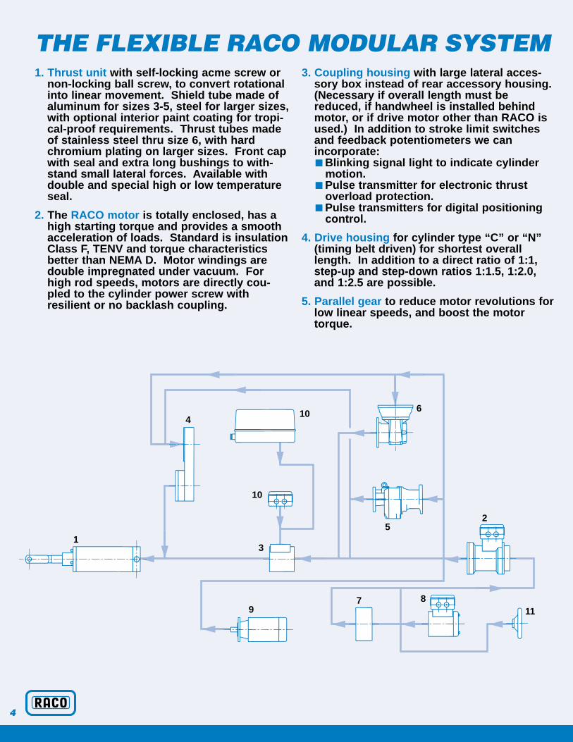
1. Thrust unit with self-locking acme screw ornon-locking ball screw, to convert rotationalinto linear movement. Shield tube made ofaluminum for sizes 3-5, steel for larger sizes,with optional interior paint coating for tropi-cal-proof requirements. Thrust tubes madeof stainless steel thru size 6, with hardchromium plating on larger sizes. Front capwith seal and extra long bushings to with-stand small lateral forces. Available withdouble and special high or low temperatureseal.
2. The RACO motor is totally enclosed, has ahigh starting torque and provides a smoothacceleration of loads. Standard is insulationClass F, TENV and torque characteristicsbetter than NEMA D. Motor windings aredouble impregnated under vacuum. Forhigh rod speeds, motors are directly cou-pled to the cylinder power screw withresilient or no backlash coupling.
3. Coupling housing with large lateral acces-sory box instead of rear accessory housing.(Necessary if overall length must bereduced, if handwheel is installed behindmotor, or if drive motor other than RACO isused.) In addition to stroke limit switchesand feedback potentiometers we can incorporate:■ Blinking signal light to indicate cylinder
motion.■ Pulse transmitter for electronic thrust
overload protection.■ Pulse transmitters for digital positioning
control.
4. Drive housing for cylinder type “C” or “N”(timing belt driven) for shortest overalllength. In addition to a direct ratio of 1:1,step-up and step-down ratios 1:1.5, 1:2.0,and 1:2.5 are possible.
5. Parallel gear to reduce motor revolutions forlow linear speeds, and boost the motortorque.
THE FLEXIBLE RACO MODULAR SYSTEM
410
10
31
6
52
879 11
4

6. Right angle gear to reduce motor revolu-tions for slow speeds, and to reduce over-all length.
7. Electro-magnetic brake type “L” (appliesbraking force when power is off) isrequired with a ball screw or a high-leadacme screw, neither of which is self-lock-ing. Exact positioning applications alsorequire this brake. Depending on theapplication, the brake can be wired for ashort, medium, or fast reaction time.
Electro-magnetic brake type “B” (appliesbraking force when power is on) for safetyapplications requiring the cylinder to backdrive to a desired safe position incase of a power failure. Counterweightsor springs must be used in connectionwith non-locking ball screws to providebackdriving force.
8. Rear accessory housing for stroke limitswitches, feedback potentiometer, andposition emitter.
9. Many types of customer specified motorssuch as AC, DC, servo, stepping motorsand gear motors are adaptable.
10.Lateral accessory housings can be usedon all cylinders. All the available acces-sories can be mounted in these housings.
11. Solid handwheel is available for manualoperation/adjustment of the cylinder.Optional mechanical and electrical disen-gaging mechanisms are also available. All accessories are installed in the lateralaccessory housing when the cylinder isfurnished with a hand wheel.
CUSTOM MADE LINEAR CYLINDERSFOR YOUR APPLICATION
TYPE “T”
TYPE “N”
TYPE “C”
TYPE “A”
TYPE “M”
5

The RACO Modular System allows a wide variety of combinations in type, size, thrust,speed, etc. The charts on the next pages listthe standard cylinders. Numerous special combinations are available. Call us if yourdesired thrust/speed/stroke is not listed.
THRUST UNIT SIZE
There are 11 RACO cylinder sizes available.The sizes 3-8 are available as “A”, “C”, “M”,“N”, and “T” type with the special RACOCylinder Duty Motor.The sizes 9-11 are generally furnished with anappropriate commercial parallel or right anglegear motor.
THRUST (LINEAR FORCE)
RACO Electric Linear cylinders cover a thrustrange from 65 lb. to 132000 lb. The listedthrust is the nominal force. Considerably higher thrusts are permissible for a certain limited number of cycles or limited time.
STROKE (LINEAR TRAVEL)
The standard available strokes are:
The selection charts are listing the availablestroke ranges for a certain size, thrust, speed.
All standard strokes are not available in all sizes.
SPEED (LINEAR VELOCITY)
The listed speed (linear velocity) of thecylinder rod is based on the RACO high slip,cylinder duty AC motor full load speed. Tomaintain a certain desired linear velocity andboost the motor torque, appropriate gearreducers and/or a timing belt stage is utilized.
SCREW TYPE/RACO MOTOR SIZE
This column in the charts gives valuable infor-mation about the utilized screw dimensionsand the recommended RACO motor size.
The meaning of the listed code is as follows:
Example:
*Additional non-listed special leads are available upon request.**Ball screws require holding brakes.
The above mentioned screw data can be usedto size and select an AC, DC, Servo orStepping motor or motor gearbox combinationsuitable for your application. See section “Formulas for motor sizing.”
STANDARD RACO ELECTRIC LINEARCYLINDER COMBINATIONS
in 3.9 7.9 11.8 15.7 19.7 23.6 31.5
mm 100 200 300 400 500 600 800
in 39.4 47.2 55.1 63.0 70.9 78.7
mm 1000 1200 1400 1600 1800 2000
T 20 x 3 / 4
T - Acme ScrewK - Ball Screw**
Screw diameter (mm)
Screw lead* (mm)
RACO Motor size
6

SELECTION CHARTS ELECTRIC LINEAR CYLINDER TYPE “A”(with direct drive motors)
SELECTION CHARTS ELECTRIC LINEAR CYLINDER TYPE “C”(driven via a timing belt)
THRUST THRUST STROKE RANGE SPEED SCREW TYPE/UNIT (LINEAR FORCE) (LINEAR TRAVEL) (LINEAR VELOCITY) RACOSIZE
LB N in mm in/s mm/sMOTOR SIZE
3 220 1000 3.9-39.4 100-1000 1.9 48 T14x2/33.9-15.7 100-400 5.7 144 K14x6/3
4 550 2500 3.9-39.4 100-1000 2.8 71 T20x3/43.9-39.4 100-1000 5.7 144 T20x3/4 K20x6/4
5 1100 5000 3.9-39.4 100-1000 3.7 93 T26x4/53.9-39.4 100-1000 7.6* 193 T26x8/5 K25x8/5
6 2200 10000 7.9-78.7 200-2000 4.7 119 T32x5/67.9-78.7 200-2000 7.6* 193 T32x8/67.9-78.7 200-2000 9.4 238 K32-10/6
7 3300 15000 7.9-78.7 200-2000 5.7 144 T40x6/7
THRUST THRUST STROKE RANGE SPEED SCREW TYPE/UNIT (LINEAR FORCE) (LINEAR TRAVEL) (LINEAR VELOCITY) RACOSIZE
LB N in mm in/s mm/sMOTOR SIZE
3 440 2000 3.9-39.4 100-1000 0.9 22 T14x2/3220 1000 3.9-39.4 100-1000 1.9 48 T14x2/3
3.9-15.7 100-400 3.7 93 K14x6/33.9-15.7 100-400 5.7 144 K14x6/3
4 1100 5000 3.9-39.4 100-1000 1.4 35 T20x3/4550 2500 3.9-39.4 100-1000 2.8 71 T20x3/4 K20x6/4
3.9-39.4 100-1000 5.7 144 T20x3/4 K20x6/45 2200 10000 3.9-39.4 100-1000 1.4 35 T26x4/5
1100 5000 3.9-39.4 100-1000 3.7 93 T26x4/5 K25x8/43.9-39.4 100-1000 7.6 193 T26x8/5 K25x8/5
6 2200 10000 7.9-78.7 200-2000 2.8 71 T32x5/57.9-78.7 200-2000 4.7 119 T32x5/5 K32x10/57.9-78.7 200-2000 7.6 193 T32x5/57.9-78.7 200-2000 9.4 238 K32x10/6
7 4400 20000 7.9-78.7 200-2000 2.8 71 T40x6/73300 15000 7.9-78.7 200-2000 5.7 144 T40x6/7 K40x12/6
7.9-78.7 200-2000 7.6 193 K40x12/7
7
*Not Self Locking - Brake “L” Recommended

SELECTION CHARTS Cont. ELECTRIC LINEAR CYLINDER TYPE “M”(driven by parallel gear motor)
ELECTRIC LINEAR CYLINDERTYPE “N”
(driven by parallel gear motor via timing belt)
THRUST THRUST STROKE RANGEUNIT (LINEAR FORCE) (LINEAR TRAVEL)SIZE
LB N in mm
3 440 2000 3.9-39.4 100-10003.9-39.4 100-10003.9-39.4 100-10003.9-39.4 100-10003.9-15.7 100-4003.9-15.7 100-4003.9-15.7 100-400
220 1000 3.9-15.7 100-4004 1100 5000 3.9-39.4 100-1000
3.9-39.4 100-10003.9-39.4 100-10003.9-39.4 100-1000
550 2500 3.9-39.4 100-10005 2200 10000 3.9-39.4 100-1000
3.9-39.4 100-10003.9-39.4 100-10003.9-39.4 100-1000
1100 5000 3.9-39.4 100-10006 4400 20000 7.9-78.7 200-2000
7.9-78.7 200-20007.9-78.7 200-20007.9-78.7 200-2000
2200 10000 7.9-78.7 200-20007.9-78.7 200-2000
7 8800 40000 7.9-78.7 200-20007.9-78.7 200-20007.9-78.7 200-20007.9-78.7 200-2000
4400 20000 7.9-78.7 200-20003300 15000 7.9-78.7 200-2000
8 17600 80000 7.9-78.7 200-20007.9-78.7 200-20007.9-78.7 200-2000
13200 60000 7.9-78.7 200-20008800 40000 7.9-78.7 200-2000
7.9-78.7 200-20009 33000 150000 7.9-78.7 200-2000
7.9-78.7 200-20007.9-78.7 200-20007.9-78.7 200-20007.9-78.7 200-2000* Commercial Gear Motor
* Commercial Gear Motor
THRUST THRUST STROKE RANGE SPEED SCREW TYPE/UNIT (LINEAR FORCE) (LINEAR TRAVEL) (LINEAR VELOCITY) RACOSIZE
LB N in mm in/s mm/sMOTOR SIZE
3 440 2000 3.9-39.4 100-1000 0.2 5 T14x2/33.9-39.4 100-1000 0.5 12 T14x2/33.9-39.4 100-1000 0.7 17 T14x2/33.9-39.4 100-1000 0.9 22 T14x2/3 K14x6/33.9-15.7 100-400 0.2 5 K14x6/33.9-15.7 100-400 0.5 12 K14x6/33.9-15.7 100-400 0.9 22 K14x6/3
220 1000 3.9-15.7 100-400 1.9 48 K14x6/34 1100 5000 3.9-39.4 100-1000 0.2 5 T20x3/3 K20x6/3
3.9-39.4 100-1000 0.5 12 T20x3/3 K20x6/33.9-39.4 100-1000 0.7 17 T20x3/4 K20x6/33.9-39.4 100-1000 1.4 35 T20x3/4 K20x6/4
550 2500 3.9-39.4 100-1000 2.8 71 K20x6/45 2200 10000 3.9-39.4 100-1000 0.2 5 T26x4/3 K25x8/3
3.9-39.4 100-1000 0.5 12 T26x4/4 K25x8/33.9-39.4 100-1000 0.7 17 T26x4/4 K25x8/43.9-39.4 100-1000 1.4 35 T26x4/5 K25x8/4
1100 5000 3.9-39.4 100-1000 3.7 93 K25x8/46 4400 20000 7.9-78.7 200-2000 0.2 5 T32x5/4 K32x10/3
7.9-78.7 200-2000 0.5 12 T32x5/4 K32x10/47.9-78.7 200-2000 0.7 17 T32x5/5 K32x10/47.9-78.7 200-2000 1.4 35 T32x5/5 K32x10/5
2200 10000 7.9-78.7 200-2000 2.8 71 K32x10/57.9-78.7 200-2000 4.7 119 K32x10/5
7 8800 40000 7.9-78.7 200-2000 0.2 5 T40x6/5 K40x12/57.9-78.7 200-2000 0.5 12 T40x6/5 K40x12/57.9-78.7 200-2000 0.7 17 T40x6/5 K40x12/57.9-78.7 200-2000 1.4 35 T40x6/6 K40x12/5
4400 20000 7.9-78.7 200-2000 2.8 71 T40x6/6 K40x12/53300 15000 7.9-78.7 200-2000 5.7 144 K40x12/6
8 17600 80000 7.9-78.7 200-2000 0.2 5 T65x10/5 K63x16/57.9-78.7 200-2000 0.5 12 T65x10/67.9-78.7 200-2000 0.7 17 T65x10/6 K63x16/5
13200 60000 7.9-78.7 200-2000 1.2 30 K63x16/68800 40000 7.9-78.7 200-2000 1.4 35 T65x10/6
7.9-78.7 200-2000 2.8 71 K63x16/69 33000 150000 7.9-78.7 200-2000 0.2 5 K80x25/*
7.9-78.7 200-2000 0.5 12 K80x25/*7.9-78.7 200-2000 0.7 17 K80x25/*7.9-78.7 200-2000 0.9 22 K80x25/*7.9-78.7 200-2000 1.4 35 K80x25/*
8

R ELECTRIC LINEAR CYLINDER TYPE “T”
(driven by a right angle gearbox)
E SPEED SCREW TYPE/(LINEAR VELOCITY) RACO
in/s mm/sMOTOR SIZE
0.2 5 T14x2/30.5 12 T14x2/30.7 17 T14x2/30.9 22 T14x2/30.2 5 K14x6/30.5 12 K14x6/30.9 22 K14x6/31.9 48 K14x6/30.2 5 T20x3/3 K20x6/30.5 12 T20x3/3 K20x6/30.7 17 T20x3/4 K20x6/31.4 35 T20x3/4 K20x6/42.8 71 K20x6/40.2 5 T26x4/3 K25x8/30.5 12 T26x4/4 K25x8/30.7 17 T26x4/4 K25x8/41.4 35 T26x4/5 K25x8/43.7 93 K25x8/40.2 5 T32x5/4 K32x10/30.5 12 T32x5/4 K32x10/40.7 17 T32x5/5 K32x10/41.4 35 T32x5/5 K32x10/52.8 71 K32x10/54.7 119 K32x10/50.2 5 T40x6/5 K40x12/50.5 12 T40x6/5 K40x12/50.7 17 T40x6/5 K40x12/51.4 35 T40x6/6 K40x12/52.8 71 T40x6/6 K40x12/55.7 144 K40x12/60.2 5 T65x10/5 K63x16/50.5 12 T65x10/60.7 17 T65x10/6 K63x16/51.2 30 K63x16/61.4 35 T65x10/62.8 71 K63x16/60.2 5 K80x25/*0.5 12 K80x25/*0.7 17 K80x25/*0.9 22 K80x25/*1.4 35 K80x25/*
THRUST THRUST STROKE RANGE SPEED SCREW TYPE/UNIT (LINEAR FORCE) (LINEAR TRAVEL) (LINEAR VELOCITY) RACOSIZE LB N in mm in/s mm/s MOTOR SIZE
3 440 2000 3.9-39.4 100-1000 0.2 5 T14x2/33.9-39.4 100-1000 0.5 12 T14x2/33.9-39.4 100-1000 0.7 17 T14x2/33.9-15.7 100-400 0.2 5 K14x6/33.9-15.7 100-400 0.5 12 K14x6/33.9-15.7 100-400 0.9 22 K14x6/3
4 1100 5000 3.9-39.4 100-1000 0.2 5 T20x3/3 K20x6/33.9-39.4 100-1000 0.5 12 T20x3/3 K20x6/33.9-39.4 100-1000 0.7 17 T20x3/3 K20x6/3
5 2200 10000 3.9-39.4 100-1000 0.2 5 T26x4/3 K25x8/33.9-39.4 100-1000 0.5 12 T26x4/4 K25x8/33.9-39.4 100-1000 0.7 17 T26x4/4 K25x8/43.9-39.4 100-1000 1.4 35 K25x8/4
6 4400 20000 7.9-78.7 200-2000 0.2 5 T32x5/4 K32x10/37.9-78.7 200-2000 0.5 12 T32x5/4 K32x10/47.9-78.7 200-2000 0.7 17 T32x5/5 K32x10/4
7 8800 40000 7.9-78.7 200-2000 0.2 5 T40x6/5 K40x12/57.9-78.7 200-2000 0.5 12 T40x6/5 K40x12/57.9-78.7 200-2000 0.7 17 T40x6/5 K40x12/57.9-78.7 200-2000 1.4 35 K40x12/5
8 17600 80000 7.9-78.7 200-2000 0.2 5 T65x10/5 K63x16/57.9-78.7 200-2000 0.5 12 T65x10/67.9-78.7 200-2000 0.7 17 T65x10/6 K63x16/57.9-78.7 200-2000 1.2 30 K63x16/6
8800 40000 7.9-78.7 200-2000 1.4 35 T65x10/69 33000 150000 7.9-78.7 200-2000 0.2 5 K80x25/*
7.9-78.7 200-2000 0.5 12 K80x25/*7.9-78.7 200-2000 0.7 17 K80x25/*7.9-78.7 200-2000 0.9 22 K80x25/*7.9-78.7 200-2000 1.4 35 K80x25/*
10 66000 300000 7.9-78.7 200-2000 0.2 5 K100x25/*7.9-78.7 200-2000 0.5 12 K100x25/*7.9-78.7 200-2000 0.7 17 K100x25/*7.9-78.7 200-2000 0.9 22 K100x25/*7.9-78.7 200-2000 1.4 35 K100x25/*
11 132000 600000 7.9-78.7 200-2000 0.2 5 K125x30/*7.9-78.7 200-2000 0.5 12 K125x30/*7.9-78.7 200-2000 0.7 17 K125x30/*7.9-78.7 200-2000 0.9 22 K125x30/*7.9-78.7 200-2000 1.4 35 K125x30/*
* Commercial Gear Motor
9
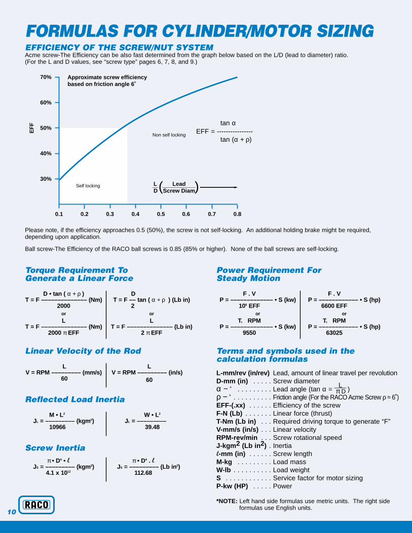
FORMULAS FOR CYLINDER/MOTOR SIZINGEFFICIENCY OF THE SCREW/NUT SYSTEMAcme screw-The Efficiency can be also fast determined from the graph below based on the L/D (lead to diameter) ratio.(For the L and D values, see “screw type” pages 6, 7, 8, and 9.)
Please note, if the efficiency approaches 0.5 (50%), the screw is not self-locking. An additional holding brake might be required,depending upon application.
Ball screw-The Efficiency of the RACO ball screws is 0.85 (85% or higher). None of the ball screws are self-locking.
Torque Requirement To Generate a Linear Force
Linear Velocity of the Rod
Reflected Load Inertia
Screw Inertia
Power Requirement For Steady Motion
Terms and symbols used in the calculation formulas
L-mm/rev (in/rev) Lead, amount of linear travel per revolutionD-mm (in) . . . . . Screw diameter
Lα − ˚ . . . . . . . . . Lead angle (tan α = π D )ρ − ̊ . . . . . . . . . . Friction angle (For the RACO Acme Screw ρ ≈ 6˚) EFF-(.xx) . . . . . . Efficiency of the screwF-N (Lb) . . . . . . . Linear force (thrust)T-Nm (Lb in) . . . Required driving torque to generate “F”V-mm/s (in/s) . . . Linear velocityRPM-rev/min . . . Screw rotational speedJ-kgm2 (Lb in2) . Inertial-mm (in) . . . . . . Screw lengthM-kg . . . . . . . . . Load massW-lb . . . . . . . . . . Load weightS . . . . . . . . . . . . Service factor for motor sizingP-kw (HP) . . . . . Power
*NOTE: Left hand side formulas use metric units. The right side formulas use English units.
0.1 0.2 0.3 0.4 0.5 0.6 0.7 0.8
30%
40%
50%
60%
70%
EF
F
Approximate screw efficiency based on friction angle 6˚
Self locking
Non self locking
L LeadD Screw Diam( )
D • tan ( α + ρ )T = F –––––––––––––– (Nm)
2000or
LT = F –––––––––––––– (Nm)
2000 πEFF
DT = F –– tan ( α + ρ ) (Lb in)
2or
LT = F –––––––––––––– (Lb in)
2 πEFF
LV = RPM ––––––––– (mm/s)
60
LV = RPM ––––––––– (in/s)
60
M • L2
JL = ––––––––– (kgm2)10966
W • L2
JL = ––––––––– 39.48
π • D4 • lJS = ––––––––– (kgm2)
4.1 x 10¹²
π • D4 . lJS = ––––––––– (Lb in2)
112.68
F . VP = ––––––––––––– • S (kw)
106 EFFor
T. RPMP = ––––––––––––– • S (kw)
9550
F . VP = –––––––––––– • S (hp)
6600 EFFor
T. RPMP = –––––––––––– • S (hp)
63025
tan αEFF = ----------------
tan (α + ρ)
10

DIMENSIONSTHRUST UNIT
COUPLING HOUSINGUNIT SIZE
3/4 5/6/7 8in mm in mm in mm
∅ d 3.937 100 6.693 170 7.874 200L* 3.937 100 7.09 180
*NOTE: Lengths vary with gearbox selection.
UNIT SIZE3 4 5 6 7 8 9 10 11
in mm in mm in mm in mm in mm in mm in mm in mm in mma 3.31 84 5.197 132 4.72 120 7.01 178 7.2 183 7.48 190 9.65 245 17.44 443 17.44 443a1 8.4 213.36 13 330.2 14 355.6 18.5 470 21.4 543.56 22.9 581.66 26.75 679.5 35.8 909.32 41.3 1049.02a4 4.488 114 7.28 185 7.52 191 10 254 10.51 267 11.02 280a10 0.55 14 .055 14 .709 18 1.063 27 1.89 48 3.52 89.5 6.69 170 9.19 233.5 9.84 250b .787 20 1.26 32 1.575 40 2.165 55 3.15 80b1 .40 10.2 .65 16.5 .787 20 1.10 28 1.26 32b2 1.575 40 2.5 63.5 1.575 40 2.2 56 2.36 60b3 .394 10 .63 16 .787 20 1.102 28 1.59 40.5b4 1.139 29 1.5 38 2.42 61.5 2.869 73 4.61 117 4.61 117 6.06 154 9.06 230 10.43 265b5 .394 10 .63 16 .984 25 1.18 30 1.969 50 1.97 50 2.76 70 3.937 100 4.331 110b6 .55 14 .825 21 .787 20 .866 22 1.575 40 1.58 40 2.17 55 2.76 70 3.15 80b7 .415 10.5 .563 14.3 .629 16 .75 19 1.457 37 1.46 37 1.93 49 2.76 70 2.76 70d1 2.955 75 3.94 100 4.5 114 5.5 140 7.087 180 8.66 220 9.65 245 11.73 298 12.76 324d2 .85 21.6 1.165 29.6 1.480 37.6 1.953 49.6 2.362 60 3.819 97 6.102 155 6.890 175 6.890 175d4 5.51 140 7.87 200 7.87 200 9.843 250 11.81 300 13.78 350d5 4.53 115 6.5 165 6.5 165 7.91 201 10.43 265 11.81 300d6 3.74 95 5.118 130 5.118 130 7.09 180 9.06 230 9.84 250d7 .354 9 .43 11 .512 13 .512 13 .55 14 .71 18d8 .394 10 .59 15 .59 15 .63 16 .787 20 .787 20d9 .118 3 .118 3 .118 3 .157 4 .157 4 .197 5e10 .868 22 .868 22 1.181 30 1.575 40 1.575 40 1.969 50 2.756 70 3.937 100 4.331 110e11 3.94 100 3.94 100 6.89 175 6.89 175 7.87 200 9.65 245 12.99 330 16.54 420 18.11 460e12 5.5 140 5.5 140 9.25 235 10.04 255 11.02 280 13.58 345 18.5 470 24.41 620 27.56 700
∅ d
∅ b3∅ d4
∅ d6∅ d7
∅ d5 B.C.
L
b7b1
b2
a10 e12
e11
∅ e10
∅ d2
∅ b3
∅ d1∅ d4
a4
a
b
d9
d8
∅ b6
b4
OPTIONALROD END
OPTIONAL FRONTMOUNTING FLANGE
FRONT MOUNTINGFLANGE DETAIL a1 + STROKE
11
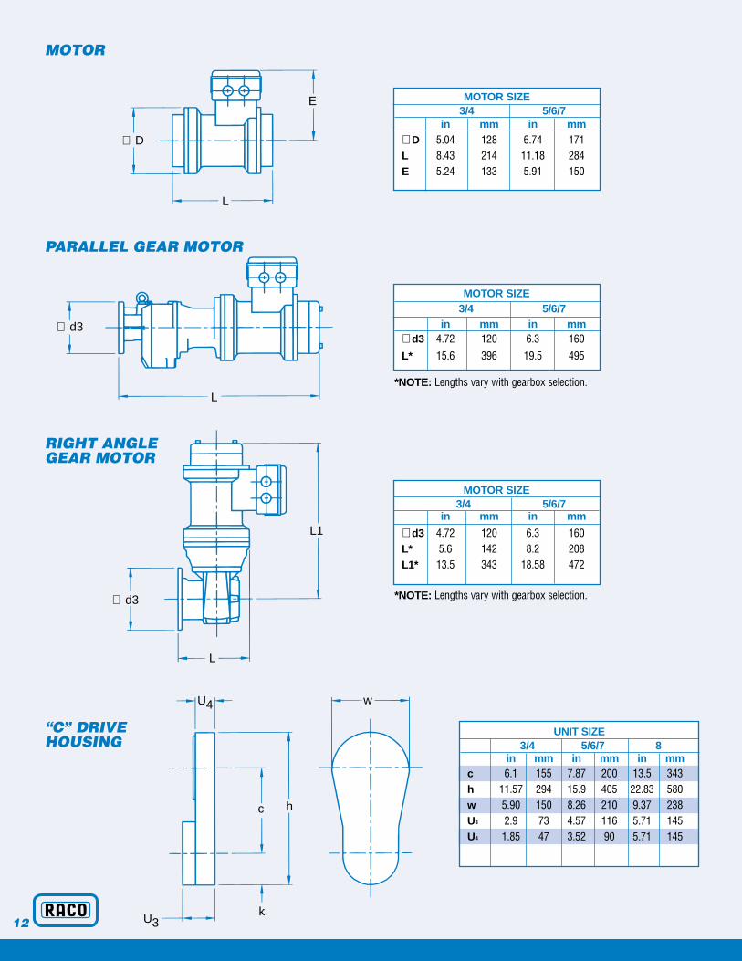
MOTOR
PARALLEL GEAR MOTOR
RIGHT ANGLE GEAR MOTOR
“C” DRIVEHOUSING
*NOTE: Lengths vary with gearbox selection.
*NOTE: Lengths vary with gearbox selection.
UNIT SIZE3/4 5/6/7 8
in mm in mm in mmc 6.1 155 7.87 200 13.5 343h 11.57 294 15.9 405 22.83 580w 5.90 150 8.26 210 9.37 238U3 2.9 73 4.57 116 5.71 145U4 1.85 47 3.52 90 5.71 145
MOTOR SIZE3/4 5/6/7
in mm in mm∅ D 5.04 128 6.74 171L 8.43 214 11.18 284E 5.24 133 5.91 150
MOTOR SIZE3/4 5/6/7
in mm in mm
∅ d3 4.72 120 6.3 160L* 5.6 142 8.2 208L1* 13.5 343 18.58 472
MOTOR SIZE3/4 5/6/7
in mm in mm∅ d3 4.72 120 6.3 160L* 15.6 396 19.5 495
∅ D
∅ d3
L
L
∅ d3
L1
L
U4
U3
c
w
k
h
E
12
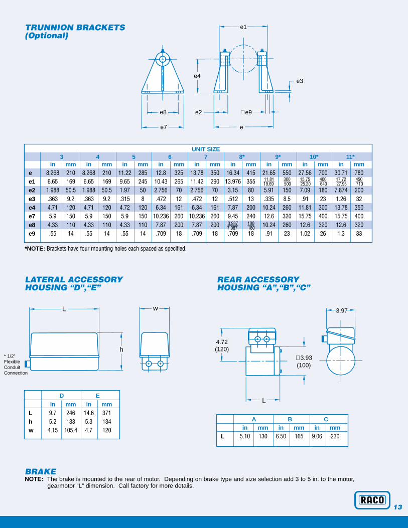
BRAKENOTE: The brake is mounted to the rear of motor. Depending on brake type and size selection add 3 to 5 in. to the motor,
gearmotor “L” dimension. Call factory for more details.
TRUNNION BRACKETS (Optional)
LATERAL ACCESSORYHOUSING “D”,“E”
REAR ACCESSORYHOUSING “A”,“B”,“C”
A B Cin mm in mm in mm
L 5.10 130 6.50 165 9.06 230
UNIT SIZE3 4 5 6 7 8* 9* 10* 11*
in mm in mm in mm in mm in mm in mm in mm in mm in mme 8.268 210 8.268 210 11.22 285 12.8 325 13.78 350 16.34 415 21.65 550 27.56 700 30.71 780e1 6.65 169 6.65 169 9.65 245 10.43 265 11.42 290 13.976 355 11.81 300 15.75 400 17.72 450
e2 1.988 50.5 1.988 50.5 1.97 50 2.756 70 2.756 70 3.15 80 5.91 150 7.09 180 7.874 200e3 .363 9.2 .363 9.2 .315 8 .472 12 .472 12 .512 13 .335 8.5 .91 23 1.26 32e4 4.71 120 4.71 120 4.72 120 6.34 161 6.34 161 7.87 200 10.24 260 11.81 300 13.78 350e7 5.9 150 5.9 150 5.9 150 10.236 260 10.236 260 9.45 240 12.6 320 15.75 400 15.75 400e8 4.33 110 4.33 110 4.33 110 7.87 200 7.87 200 3.937 100 10.24 260 12.6 320 12.6 320e9 .55 14 .55 14 .55 14 .709 18 .709 18 .709 18 .91 23 1.02 26 1.3 33
*NOTE: Brackets have four mounting holes each spaced as specified.
D Ein mm in mm
L 9.7 246 14.6 371h 5.2 133 5.3 134w 4.15 105.4 4.7 120
19.69 500 25.20 640 27.95 710
7.087 180
L
L
w
4.72(120)
∅ 3.93(100)
e1
e3
e8
e7
e2
e4
e
∅ e9
3.97
h* 1/2” Flexible Conduit Connection
13

STANDARD/OPTIONAL EQUIPMENT
ACCESSORY HOUSING/ACCESSORIESINSTALLATION OF ACCESSORIES
Accessory Accessories which can be installed Accessory Accessories which can be installed These accessories canHousing Housing be added to D and E
1 pr. SPDT stroke limit switches 1 pr. SPDT stroke limit switches2 pr. SPDT stroke limit switches 1 pr. SPDT switches + potA 1 Potentiometer D 2 pr. SPDT switches1 Electronic position emitter 4-20mA DMU1 1 Multi-turn pot
1 Pulse transmitter for 1 pr. SPDT switches + pot 1 pr. SPDT switches + DMU1 RPM4, RPM5, RPM6 or pulse1 pr. SPDT switches + tandem pot 2 pr. SPDT switches + tandem pot feedback signalB 1 pr. SPDT switches + DMU1 2 pr. SPDT switches + pot1 Multi-turn pot 2 pr. SPDT switches + tandem pot
2 pr. SPDT switches + DMU1E3 pr. SPDT switches
2 pr. SPDT switches + pot 3 pr. SPDT switches + pot2 pr. SPDT switches + tandem pot 3 pr. SPDT switches + tandem pot2 pr. SPDT switches + DMU1 3 pr. SPDT switches + DMU1C3 pr. SPDT switches3 pr. SPDT switches + pot
Accessory housings D and E, mounted onto motor or coupling housing will also be used to install integral reversing motor starters (optional) F 1 Pulse transmitter for RPM4,RPM5 or including transformer, heater, and terminal blocks. In this case, SPDT
COUPLING RPM6 or for pulse feedback signal limit switches will be pre-wired directly to motor starters.HOUSING All accessory housings are equipped with 1/2” flexible conduit fitting.
One pair SPDT stroke limit switches is standard, all other accessories are optional.
14
Standard OptionalFork Type Front Clevis (Standard on sizes 2-7) XSpherical Rod End (Standard on sizes 8-11) X
Trunnion Mounting Pins XTrunnion Mounting Brackets XRigid Foot Mount for T.M. Brackets XRear Clevis Mounting (Only certain models, consult factory) XFlange Mounting (Consult factory) XHand Wheel XHand Wheel with Disengaging Mechanism and Elec. Interlock Switch XFlexible Rod Covers XSolid Rod Covers XHigh Temp Rod Covers XWiper Seal in Front Cap XDouble Wiper Seal in Front Cap XHigh Temperature Wiper Seal in Front Cap XHigh Temperature Lubricant XStainless Steel or Hard Chrome Plated Thrust Tube XWeather Proof Cylinder (NEMA 4 Equivalent /IP54) XWeather Proof Motor (TENV/IP54) XClass “F” Motor Insulation XClass “H” Motor Insulation XTropical Proof Corrosion Protection Package XExplosion Proof (Commercial Motor UL. Approved) XMotor Thermal Switches XMotor Thermistor Sensors (Standard with RPM4/RPM5/RPM6) XRACO Motor Warranty 2 years (4 years with RPM4/RPM5/RPM6) X

ACCESSORIES, ELECTRIC SWITCHES,FEEDBACK SIGNALS, ELECTRONIC CONTROLSRACO International offers a wide variety ofoptional accessories such as built in limitswitches, position output signal generatingdevices, electronic thrust controls, positioncontrols electronics, etc. Utilizing theseoptional accessories, a remote and automaticcontrol of the RACO Electric Linear Cylinder
is easily accomplished. Using the positionoutput signals from the cylinders, they canalso be connected into an appropriate exist-ing control system, such as PLC or comput-er. (For more details about the listed acces-sories contact factory.)
INPUT CONTROL DEVICEManual dial position controller “SG2” to select 0-100% stroke
VISUAL MONITORING DEVICEAnalog Position Indicator “IA 72” to visualize 0-100% stroke
NOTE: A wide variety of other customer specified signal generating devices, controls and displays are available.
SIGNALGENERATINGACCESSORIES
SPDT Limit Switches(up to 12)
Single or Multi TurnPotentiometer
Potentiometer “DMU1”
Pulse generator “DIG1” or “DIG2” with Pulse Wheel“DIR”
SIGNAL TYPE
Open/Closed Contacts
Analog Resistance/Voltage(0-500, 0-1 K ohm) propor-tional to stroke
Analog Current (4-20 mA)Proportional to stroke
Screw Speed proportionalpulse frequency, stroke proportional pulse counts
RACO ELECTRICCONTROLS
Remote controlled electronic limit switch “GW 1-2” or “GW 1-3”
Position control “FS2” or “FS3”
Electronic thrust overloadprotection “RPM4”, “RPM5”,or “Digital RPM6”
15

RACO International, Inc.3350 Industrial Blvd.Bethel Park, PA 15102(888) BUY-RACO (888) 289-7226Ph: (412) 835-5744Fx: (412) 835-0338email: [email protected] page: www.racointernational.com
© 2001 RACO International, Inc.
RACO ELECTRIC ACTUATORS FOR TODAY’S INDUSTRYOther Products Offered By RACO
RACO Compact■ Smaller installed envelope size
■ Thrust capacities to 9000 lbs.
■ Standard stroke lengths to 23.6 inches
■ Ball or acme power screw thread configuration
■ Multiple leads available in every size to optimize motor / reduction / output speed capability
■ Complete line of standard controls and options
■ ISO 9001 Manufacturing
■ Typical delivery 2-3 weeks
RACO RM■ Available in seven sizes to 10,000 lb-ft of torque
■ Fractional or multiple turn rotations
■ Output speeds thru 90 degrees in 1 to 30 seconds
■ Hollow or solid shaft output
■ Adjustable rotation limit switches
■ Analog or digital position feedback
■ Electronic torque control
■ Modular design allows custom solutions
RACO LMRACO 2060RODLESS CYLINDERS■ Acme, Ballscrew or Synchronous Belt Type ■ Carriage on Slides or Wheels ■ Speeds up to 400 in/sec. ■ Strokes in excess of 40 ft. ■ Thrust up to 4500 lb. ■ Servo, Stepper, AC or DC Motor Driven ■ Custom Controls and Systems
4-01