MACS HEAVY DUTY OFF-ROAD TECHNICAL … Duty Off-Road Technical Session Sherwood Wheeler, Supervisor...
96
© 2014 AGCO Corporation MACS HEAVY DUTY OFF-ROAD TECHNICAL SESSION February 18, 2017 Anaheim Marriott AGCO Equipment HVAC Service and Repair
Transcript of MACS HEAVY DUTY OFF-ROAD TECHNICAL … Duty Off-Road Technical Session Sherwood Wheeler, Supervisor...

© 2014 AGCO Corporation
MACS HEAVY DUTY
OFF-ROAD TECHNICAL SESSION
February 18, 2017 Anaheim MarriottAGCO Equipment HVAC Service and Repair

© 2014 AGCO Corporation
AGCO Equipment HVAC Service and Repair
February 18, 2017MACS 2017 Training Event & Trade Show, Anaheim, CAHeavy Duty Off-Road Technical Session
Sherwood Wheeler, Supervisor Dealer Technical Support
1

© 2014 AGCO Corporation
AGCO Equipment HVAC Service and Repair
Product Information Page 4 1
2
Temperature Testing Page 27
Refrigerant Capacities Page 46
Appendix Page 87
2
3
4

© 2014 AGCO Corporation
PRODUCT INFORMATION
Application Equipment Page 4
3
Harvesting – Combines Page 7
Hay – Self Propel Windrower Page 13
Wheel Tractors Page 15
Track & Articulated Tractors Page 17

© 2014 AGCO Corporation
APPLICATION EQUIPMENT
4

© 2014 AGCO Corporation
APPLICATION EQUIPMENT
5
TerraGator 8400B ModelTSB: 16-0029A
Area: A/C Condenser
Issue: Crack can develop at the welds for the mounting tab.
The condenser is identified by the cross braces observed on the rear side when it is rotated forward for servicing as pictured below.

© 2014 AGCO Corporation
APPLICATION EQUIPMENT
6
Correction:The original support frame, is identified by the two cross braces (X-Frame Design) at the rear side.
The new support for the condenser is a 1-inch box Tube Frame Design and does not use the cross braces.
In addition to the new tube frame design, the mounting for the condenser has also changed. The condenser is now mounted at each end with two rubber isolator mounts (1), and rubber bumpers (2), at the top and bottom.
SupportOriginal New

© 2014 AGCO Corporation
HARVESTING – COMBINE
7
Gleaner S9 Model Series• New Cab Introduction• New HVAC System Introduction
Models: S96, S97 and S98

© 2014 AGCO Corporation
HARVESTING – GLEANER S9 SERIES
8
Introduction of the new Vision™ Cab on the Gleaner S9 Series and features 15 percent more volume (130 ft.ᶾ) than the previous Comfortech™ cab (113 ft.ᶾ) it replaces.

© 2014 AGCO Corporation
HARVESTING – GLEANER S9 SERIES
9
New HVAC Unit
Previous Cabs: The HVAC unit is mounted below the cabin.
Vision™ Cab: The HVAC unit is mounted inside the cabin roof.

© 2014 AGCO Corporation
HARVESTING – GLEANER S9 SERIES
10
The Vision™ Cab climate control panel includes two push-buttons and two rotary knobs;
A. Power button B. Defrost buttonC. Fan speed control knobD. Temperature control knob
The LCD screen is located in the center of the controller and displays the temperature.
If a fault is detected, the code is displayed in the LCD. The fault codes and description are listed on the following two pages.
A BC D

© 2014 AGCO Corporation
HARVESTING – GLEANER S9 SERIES
11

© 2014 AGCO Corporation
HARVESTING – GLEANER S9 SERIES
12

© 2014 AGCO Corporation
HAY SELF-PROPEL WINDROWER
13
WR9800 Model Series

© 2014 AGCO Corporation
SELF-PROPEL WINDROWER
14
Model Series: WR9800
EFF S/N: AGCM98600HHS12111
Introduction: TCCI QP7H15 Compressor

© 2014 AGCO Corporation 15
WHEEL TRACTORS
MF 8600 SERIESMF 8700 SERIES
MT600D SERIESMT600E SERIES

© 2014 AGCO Corporation
WHEEL TRACTORS
16
INLET
OUTLET
Condenser with serviceable desiccant cartridge.
When servicing the desiccant cartridge, it is recommended to replace the Cartridge, A, and the Plug Kit, B, at the same time.
AB
Item Part Number QTY Description
A 4387485M1 1 Cartridge
B 4387483M1 1 Kit
C Included in item B 1 Plug
D Included in item B 2 O’Ring
MF8600 and MT600D eff s/n E352034MF8700 and MT600E start of production

© 2014 AGCO Corporation
TRACK & ARTICULATED TRACTORS
17
CHALLENGER MODELS
– MT700C Series Track Tractors– MT700D Series Track Tractors– MT700E Series Track Tractors
– MT & MTS 800C Series Track Tractors– MT & MTS 800E Series Track Tractors
– MT & MTS 900C Series Articulated Tractors– MT & MTS 900E Series Articulated Tractors

© 2014 AGCO Corporation
TRACK & ARTICULATED TRACTORS
18
CHALLENGER MT 700E/800E/900E MODEL SERIES
The following pages are an overview of some introductions beginning with model year 2015.

© 2014 AGCO Corporation
TRACK & ARTICULATED TRACTORS
19
ENGINE HEAT MANAGEMENT
• Engine air flow is directed away from the cabin.
• Additional insulation for the exhaust tube.
• Heat shielding is added to the exhaust tube and the muffler.
CHALLENGER MT 700E/800E/900E MODEL SERIES

© 2014 AGCO Corporation
TRACK & ARTICULATED TRACTORS
20
COOLING PACKAGE
New cooling package with increased capacity and efficiency.
COMPRESSOR
Sanden compressor with a higher efficiency.
CHALLENGER MT 700E/800E/900E MODEL SERIES

© 2014 AGCO Corporation
TRACK & ARTICULATED TRACTORS
21
MT700E Series. The receiver drier is vertical mounted on the left-hand side of the engine.
MT800E and MT900E Series. The receiver drier is vertical mounted on the left-hand side of the cooling package.
Receiver Drier
CHALLENGER MT 700E/800E/900E MODEL SERIES

© 2014 AGCO Corporation
TRACK & ARTICULATED TRACTORS
22
SUCTION HOSE
The suction hose from the evaporator outlet to the compressor suction port is insulated and the hose size is increased.
EVAPORATOR CAPACITY
The evaporator incorporates “rifled” coil tubes. The rifling process adds small grooves to the interior wall of the tubes. The “rifling” increases the internal surface area and turbulence inside the evaporator. The new evaporator increases the coefficient of heat transfer as the air passes across the evaporator.
CHALLENGER MT 700E/800E/900E MODEL SERIES

© 2014 AGCO Corporation
TRACK & ARTICULATED TRACTORS
23
CAB INSULATION
Higher R-value insulation material and additional insulation has been added to the cab to reduce the transfer of heat.
CHALLENGER MT 700E/800E/900E MODEL SERIES

© 2014 AGCO Corporation
TRACK & ARTICULATED TRACTORS
24
CAB INSULATION
Insulation is added to underside and outside of the cab to reduce the transfer of heat from the surrounding components.
Right Side
Left SideUnderside of Cabin
CHALLENGER MT 700E/800E/900E MODEL SERIES

© 2014 AGCO Corporation
TRACK & ARTICULATED TRACTORS
25
CAB DUCTWORK INSULATION
Insulation of the HVAC ductwork.
CHALLENGER MT 700E/800E/900E MODEL SERIES

© 2014 AGCO Corporation
TRACK & ARTICULATED TRACTORS
26
RETROFIT ENHANCEMENT KITS
Technical Service Bulletins;SB 14-0148A MT700D and MT800CSB 14-0176A MT900C Series
The informational TSB’s announced retrofit kits to allow some of the Challenger E Series A/C components to be installed as an enhancement on the Challenger MT700D, MT800C and MT900C Series tractors.
NOTE: Cab removal is required.
PARTNUMBER
QTY DESCRIPTION
584427D1 1 MT700D BASIC AC KIT
584428D1 1 MT700D DELUXE AC KIT
584228D1 1 MT800C BASIC AC KIT
584359D1 1 MT800C DELUXE AC KIT
584228D1 1 MT900C BASIC AC KIT
584359D1 1 MT900C DELUXE AC KIT
519922D1 1 RECEIVER DRIER
501145D2 1 HVAC COVER SEAL

© 2014 AGCO Corporation
AGCO Equipment HVAC Service and Repair
Product Information Page 4 1
27
Temperature Testing Page 27
Refrigerant Capacities Page 46
Appendix Page 87
2
3
4

© 2014 AGCO Corporation
TEMPERATURE TESTING - TOOLS
28
Digital Thermometer touch/clamp type
AC Gauges
Temperature Pressure (P/T)
Chart

© 2014 AGCO Corporation
TEMPERATURE TESTING - TOOLS
29
For a/c temperature testing, an infrared thermometer is not typically recommended. They are easy to use, and can provide rough measurements, but when trying to diagnosis an a/c system problem, they most often do not provide reliable data.
It is normally recommended to use a digital thermometer with touch probe for a/c temperature testing.

© 2014 AGCO Corporation
TEMPERATURE TESTING – DATA SHEETS
30See the Appendix 1, 2 and 3 at the end for full size printable copies

© 2014 AGCO Corporation
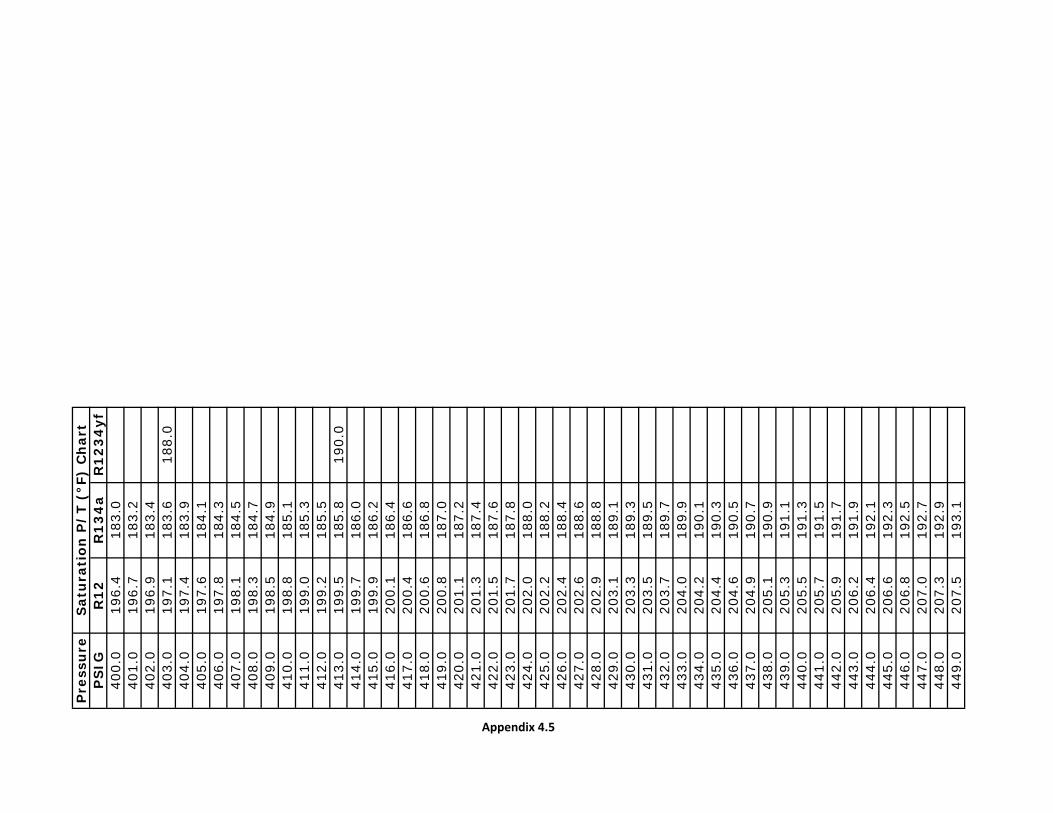
TEMPERATURE TESTING – P/T Chart
31
Saturation Properties (P/T) Chart for R12, R134a and HYF1234 can be invaluable when diagnosing an a/c problem. If you know the temperature/pressure, the user can quickly determine the corresponding value for the refrigerant type. For example one question that is commonly asked by service technicians is, what should the high side pressure be. The following two ways can be used as a quick guide or rough estimate to determine high side pressure.
1) Ambient temperature (x) 2 or (x) 2.5 = high side psi• Example: 95°F (x) 2 = 190 psi and/or 95°F (x) 2.5 = 237 psi
2) Ambient temperature + 40 = Saturation temperature
• Example: 95°F + 40 = 135°F
Consult the P/T Chart at the right and find 135°F under the R134a column to find the high side pressure range, 215-217 psi
See the Appendix (4.1, 4.2, 4.3, 4.4 and 4.5) at the end for full size printable P/T chart

© 2014 AGCO Corporation
TEMPERATURE TESTING – COOLING PACKAGE
32
• It is recommended to perform testing when the ambient air temperature is above 80°F.
• Condenser and Radiator are clean
• The engine or cooling fan is fully locked-up.
Engine Cooling Package

© 2014 AGCO Corporation
TEMPERATURE TESTING - COMPRESSOR
33
CompressorHousing Temperature: 145-165° F. Testing has shown that the housing temperature typically operates about 100°F above the suction line temperature.
What can affect housing temperature.• Refrigerant charge amount• Restriction in suction hose• Suction hose size• Suction hose near heat source or touching heater/hydraulic
line.
Low-side
psi
°F
High-side
psi
°F
Compressor Housing
°F

© 2014 AGCO Corporation
TEMPERATURE TESTING - CONDENSER
34
Condenser
It is recommended to perform testing when the ambient air temperature is above 80°F.
Measure and record the inlet and outlet temperature. The minimum differential is 20°F. The temperature drop across the condenser is affected by air flow, cleanliness of the condenser, ambient temperature, internal restriction.
CondenserAmbient air
Inlet °F
Condenser
Inlet °F
Outlet °F
Drop °F

© 2014 AGCO Corporation
TEMPERATURE TESTING - DRIER
35
Drier Inlet/Outlet
Inlet °F
Outlet °F
Drop °F
• The receiver-drier is used in conjunction with a thermal expansion valve (TXV).
• Little to no temperature differential between inlet and outlet
• Restriction at the inlet to the drier will cause high side head pressure.
• Restriction at the outlet tube will be indicated by low head pressure and little to no cooling.
NOTE: Typically the drier is located in the coolest area away from heat sources, but when this is not possible, consider insulating the drier. Overheating the drier can result in the release of moisture from the desiccant that will freeze at the TXV orifice.
Horizontal Drier
Vertical Drier
Receiver-Drier

© 2014 AGCO Corporation
TEMPERATURE TESTING – ACCUMULATOR
36
Accumulator
Inlet °F
Outlet °F
Drop °F
The suction accumulator is similar to a receiver-drier but serves a different function.
• The accumulator is used in conjunction with a fixed-orifice tube (FOT).
• The accumulator is larger than a receiver-drier in size/volume.
• The accumulator is typically at or near the evaporator outlet.
• The accumulator stores excess liquid to prevent liquid refrigerant from reaching the compressor and causing damage to the compressor.
• The accumulator assures that the compressor only receives vapor.
• The inlet and outlet temperature is about the same.
Suction Accumulator

© 2014 AGCO Corporation
TEMPERATURE TESTING – EVAPORATOR
37
The evaporator like the condenser consist of a refrigerant coil mounted in a series of thin cooling fins. It provides a maximum amount of heat transfer in a minimum amount of space.
The evaporator receives refrigerant from the “TXV” or “FOT” valve as low pressure, cold atomized liquid. As this cold refrigerant passes through the evaporator, heat moves from warm air to the cooler refrigerant.
When the liquid refrigerant receives enough heat to induce a change of state, a large quantity of heat moves from the air to the refrigerant. This causes the refrigerant to change from a low pressure, cold, atomized liquid, into a low-pressure, cold vapor. The vaporous (saturated) refrigerant then continues onto the inlet (suction) side of the compressor. Evaporator Air Temp
Air Inlet °F
Vent Outlet °F
Delta∆ °F
1. Maximum fresh air
2. Measure and record the inlet air temperature before the evaporator
3. Measure and record the air temperature after the evaporator
4. Record the temperature drop across the evaporator. The Delta∆ is dependent on system design and requirement.
Evaporator

© 2014 AGCO Corporation
TEMPERATURE TESTING – FOT
38
The fixed orifice tube (FOT) is used in conjunction with a suction accumulator. The FOT is located in the liquid line between the condenser outlet and the evaporator inlet, and is designed to meter refrigerant into the evaporator.
The most common type FOT contains no moving parts and is available with different orifice sizes depending on application. The FOT separates the high/low side of system and the control of refrigerant flow is accomplished by turning the compressor on and off.
TESTHot in and Cold out
Problem: Outlet warm to the touch would indicate a problem.
Fixed Orifice Tube INLETOUTLETOrifice Tube

© 2014 AGCO Corporation
TROUBLESHOOTING - TXV
39
The thermostatic expansion valve (TXV) is non-adjustable and is located at the inlet of the evaporator and separates the high and low side of the system.
The refrigerant flow to the evaporator must be controlled to obtain maximum cooling, while assuring complete evaporation of the liquid refrigerant within the evaporator.
The TXV “H” block design performs the following three functions.
• Metering Action, 9, changes the pressure of the incoming liquid refrigerant from high pressure, 3, to low pressure, 5.
•Modulating Action, 1 & 7, fluctuates towards the open or closed position to control the liquid refrigerant passing through the orifice, 9, at the ball valve, 4.
• Controlling Action, 1 & 8, as increase heat is sensed, 1, the valve, 8, moves toward an open position to increase refrigerant flow. An increase in compressor speed or a decreased in heat load will cause the valve to move toward a closed position.
71
2
35
6
8
9
4 10
NOTE: When the TXV is functioning properly, the evaporator core will be lightly frosted at the entrance, over all the end coils and outlet pipe.
Thermal Expansion Valve (TXV)

© 2014 AGCO Corporation
TROUBLESHOOTING - TXV
40
If the TXV is easily accessible use the following test to troubleshoot.
1. A/C compressor disengaged.
2. Apply heat for a few minutes to the TXV power element using hot air or a hot rag depending on what is readily available. This will cause the valve to fluctuate open.
3. Engage the compressor and continue to heat the power element. Record the low and high side operating pressures.
4. Cool the power element by placing a small bag of crushed ice or ice pack on the power element, and observe the low side pressure.
5. The pressure values for the two test in steps 2 and 4 must be different. If the values do not change, suspect a faulty TXV.
Example: In step 2 when heat is applied to the power element, the low side pressure increased to about 20 psi, and then in Step 3, when ice is placed on top of the power element, the low side pressure quickly decreased to about 10 psi.
Power Element

© 2014 AGCO Corporation
TROUBLESHOOTING - TXV
41
If the TXV is not easily accessible ;
The TXV is not always easily accessible on heavy-duty off highway vehicles. A technician can sometimes spend from a couple hours to several hours replacing a TXV. The following can be used as a quick way to help indicate if the TXV is working.
1. Connect manifold gauge set.
2. Ambient air temperature is above 80°F and the recirculation is set for maximum fresh air
3. Operate the system with the blower fan on high for about 5 minutes. Observe that the low side pressure increases.
4. Turn the blower fan to the low speed position and observe the low-side gauge reading. The pressure should drop 2-3 psi almost immediately. When the blower is on low speed, less air flow is moving across the evaporator and the TXV will immediately begin to fluctuate (close) restricting refrigerant into the evaporator.
5. Turn the blower fan back to the high position and observe the low-side gauge, it should rise 2-3 psi almost immediately. When the blower fan is on high, more air flow is moving across the evaporator and the TXV will immediately begin to fluctuate (open) allowing more refrigerant to enter the evaporator.
6. If the low-side gauge reading can be influenced with the blower fan speed, this indicates that the TXV is modulating.

© 2014 AGCO Corporation
TEMPERATURE TESTING – REVIEW THE DATA
42
Review the numbers

© 2014 AGCO Corporation
From the File
43
A couple of the not so normal A/C calls
Technical Help Desk

© 2014 AGCO Corporation
From the File – Poor Cooling & Low Pressures
44
Complaint: Poor cooling and the pressures are low
Work Performed: Before contacting the help desk, the service technician replaced the compressor, the receiver-drier and the TXV, but without making any difference to the cooling performance or the pressures. The technician planned to replace the condenser next, but decided to first make a phone call.
Pressure: The technician reported 125 psi high side and 2 psi low side, and also reported that the pressures look almost normal when charging the system. The age of the vehicle is about 12 years old.
Help Desk: Advised to check for a hose restriction. 1. Perform a visual inspection. 2. Measure the temperature at each end of the hoses to isolate.
Feedback: The service technician performed the visual inspection, but due to the age of the vehicle, made the decision to replace the hoses. Reported back that the issue was resolved after replacing the hoses.

© 2014 AGCO Corporation
From the File – Cannot Charge the System
45
Complaint: Unable to fully charge the system
Work Performed: Before contacting the help desk, the service technician installed a new compressor, replaced the receiver-drier, TXV, and flush the condenser for oil removal. But now, the system will only take about 1/3 of the recommended refrigerant charge and then stops.
Pressure: The technician reported that the high side and low side have the same pressure reading of 125 psi at 1000 engine rpm.
Help Desk: Advised that most likely the new compressor has been slugged with liquid and broke the suction valve.
Feedback: Installed another compressor. Evacuated the system below 1000 micron and then carefully recharged the system without any problem.

© 2014 AGCO Corporation
AGCO Equipment HVAC Service and Repair
Product Information Page 4 1
46
Temperature Testing Page 27
Refrigerant Capacities Page 46
Appendix Page 87
2
3
4

© 2014 AGCO Corporation47
REFRIGERANT CAPACITIES
Much work has gone into capturing the refrigerant capacities dating back to the early 1970’s. In some rare vintage cases, refrigerant information and refrigerant capacity is missing, but will be added once identified.
Capacity charts on the following pages will assist the service technician in properly charging the air conditioning system with the recommended amount of refrigerant.

© 2014 AGCO Corporation48
BRAND PAGEAGCO-ALLIS TRACTOR……………………………………………………………………………………….…51
AGCO SELF-PROPELLED WINDROWER/SWATHER……………………………………………………….52
AGCO STAR ARTICULATED TRACTOR…………………………………………………………………….…53
AGCO TRACTOR………………………………………………………………………………………………..…54
ALLIS CHALMERS TRACTOR………………………………………………………………………………..….55
CHALLENGER COMBINE……………………………………………………………………………………..….56
CHALLENGER SELF-PROPELLED WINDROWER/SWATHER ………………………………………….…57
CHALLENGER RUBBER TRACK & ARTICULTATED TRACTOR……………………………………….58-60
CHALLENGER WHEEL TRACTOR………………………………………………………………………….61-62
DEUTZ-ALLIS TRACTOR……………………………………………………………………………………..…..63
DEUTZ-FAHR TRACTOR……………………………………………………………………………………..…..64
FENDT TRACTOR……………………………………………………………………………………………..65-66
GLEANER COMBINE………………………………………………………………………………………….67-68
HESSTON SELF-PROPELLED WINDROWER/SWATHER ……………………………………………….…69

© 2014 AGCO Corporation49
BRAND PAGEMASSEY FERGUSON COMBINE………………………………………………………………………...…...70
MASSEY FERGUSON SELF-PROPELLED WINDROWER/SWATHER ………………………………....71
MASSEY FERGUSON TRACTOR ……..………………………………………………………………... 72-75
NEW IDEA SELF-PROPELLED WINDROWER/SWATHER …………………………………………..…..76
ROGATOR SPRAYER & APPLICATORS………………………………………………………………...77-78
SPRA COUPE SPRAYER………………………………………………………………………………………79
TERRA GATOR APPLICATORS…………………………………………………………………….………...80
VALTRA TRACTOR, DENSO®…………………………………………………………………………………81
VALTRA TRACTOR, MCC………………………………………………………………………………….…..82
WHITE COMBINE………………………………………………………………………………………….……83
WHITE NEW IDEA, UNI COMBINE…………………………………………………………………………...84
WHITE TRACTOR………………………………………………………………………………………….……85
WILLMAR…………………………………………………………………………………………………………86

© 2014 AGCO Corporation50

© 2014 AGCO Corporation51
NOTE (1) If the original R12 refrigerant has been removed and the system retrofitted to R134a, the recommended R134a capacity is 80% of the R12 amount.
NOTE: Always check the manufactures label on the compressor for proper oil type

© 2014 AGCO Corporation52

© 2014 AGCO Corporation53
NOTE Always check the label on the Sanden compressor body for the recommended oil part number

© 2014 AGCO Corporation54
NOTE (1) Service bulletin: Wheeled Tractors/Cab, Sheetmetal and AC/11-0165
NOTE Always check the label on the Sanden compressor body for the recommended oil part number

© 2014 AGCO Corporation55
NOTE (1) If the original R12 refrigerant has been removed and the system retrofitted to R134a, the recommended R134a capacity is 80% of the R12 amount.

© 2014 AGCO Corporation56
NOTE (1) Always check the label on the Sanden compressor body for the recommended oil part number

© 2014 AGCO Corporation57
NOTE (1) Always check the label on the Sanden compressor body for the recommended oil part number

© 2014 AGCO Corporation58

© 2014 AGCO Corporation59
NOTE Always check the label on the Sanden compressor body for the recommended oil part number

© 2014 AGCO Corporation60
NOTE Always check the label on the Sanden compressor body for the recommended oil part number

© 2014 AGCO Corporation61

© 2014 AGCO Corporation62

© 2014 AGCO Corporation63

© 2014 AGCO Corporation64

© 2014 AGCO Corporation65

© 2014 AGCO Corporation66

© 2014 AGCO Corporation67

© 2014 AGCO Corporation68

© 2014 AGCO Corporation69
NOTE (1) If the original R12 refrigerant has been removed and the system retrofitted to R134a, the recommended R134a capacity is 80% of the R12 amount.
NOTE (2) Always check the label on the Sanden compressor body for the recommended oil part number

© 2014 AGCO Corporation70
NOTE (1) If the original R12 refrigerant has been removed and the system retrofitted to R134a, the recommended R134a capacity is 80% of the R12 amount.
NOTE (2) Always check the label on the Sanden compressor body for the recommended oil part number

© 2014 AGCO Corporation71
NOTE (1) If the original R12 refrigerant has been removed and the system retrofitted to R134a, the recommended R134a capacity is 80% of the R12 amount.
NOTE (2) Always check the label on the Sanden compressor body for the recommended oil part number

© 2014 AGCO Corporation72

© 2014 AGCO Corporation73

© 2014 AGCO Corporation74

© 2014 AGCO Corporation75
NOTE Always check the label on the compressor body for the recommended oil part number

© 2014 AGCO Corporation76
NOTE Always check the label on the Sanden compressor body for the recommended oil part number

© 2014 AGCO Corporation77

© 2014 AGCO Corporation78

© 2014 AGCO Corporation79

© 2014 AGCO Corporation80

© 2014 AGCO Corporation81
NOTE Always check the label on the compressor body for the recommended oil part number

© 2014 AGCO Corporation82
NOTE Always check the label on the Sanden compressor body for the recommended oil part number

© 2014 AGCO Corporation83
NOTE (1) If the original R12 refrigerant has been removed and the system retrofitted to R134a, the recommended R134a capacity is 80% of the R12 amount.

© 2014 AGCO Corporation84
NOTE (1) If the original R12 refrigerant has been removed and the system retrofitted to R134a, the recommended R134a capacity is 80% of the R12 amount.

© 2014 AGCO Corporation85
NOTE (1) If the original R12 refrigerant has been removed and the system retrofitted to R134a, the recommended R134a capacity is 80% of the R12 amount.

© 2014 AGCO Corporation86
NOTE (3) If the original R12 refrigerant has been removed and the system retrofitted to R134a, the recommended R134a capacity is 80% of the R12 amount.
NOTE (2) PAG Oil - Check the label on the compressor for the correct viscosity
NOTE (1) Early models used the Seltec 488-44120 compressor with a v-belt. Later models used the Zexel compressor w/serpentine belt. No S/N break available.

© 2014 AGCO Corporation
AGCO Equipment HVAC Service and Repair
Product Information Page 4 1
87
Temperature Testing Page 27
Refrigerant Capacities Page 46
Appendix Page 87
2
3
4

REV
03
Dat
e:E
ngi
ne
Hou
rs:
Mod
el:
Ser
ial N
um
ber
:
Cir
cle:
°F o
r °C
Engi
ne F
an:
Fixe
d or
Vis
cous
Fan
1R
efri
gera
nt
char
ge a
mou
nt
inst
alle
d?
2T
est
is b
ein
g d
one
wit
h c
ab d
oors
op
ened
an
d/o
r cl
osed
?
3E
ngi
ne
RP
M (
reco
mm
end
ed 1
500
rpm
)R
PM
4E
ngi
ne
oper
atin
g te
mp
erat
ure
5P
erce
nt
Hu
mid
ity
outs
ide
% 6
Blo
wer
fan
sp
eed
set
tin
g
7A
mb
ien
t ai
r te
mp
erat
ure
2”
(50
mm
) in
fro
nt
of c
ond
ense
r
8C
omp
ress
or lo
w-s
ide/
hig
h-s
ide
pre
ssu
rePS
I
9C
omp
ress
or s
uct
ion
lin
e te
mp
erat
ure
10C
onve
rt h
igh
sid
e p
ress
ure
to
tem
per
atu
re, u
se P
T C
har
t
11C
omp
ress
or h
ousi
ng
tem
per
atu
re
12C
ond
ense
r in
let
lin
e te
mp
erat
ure
13C
ond
ense
r ou
tlet
lin
e te
mp
erat
ure
14D
rier
, tem
per
atu
re d
rop
acr
oss
the
dri
er
15E
vap
orat
or in
let
lin
e te
mp
erat
ure
16E
vap
orat
or o
utl
et li
ne
tem
per
atu
re
17Evap
orator air inlet temperature
18E
vap
orat
or a
ir o
utl
et (
ven
t) t
emp
erat
ure
Appendix 1
A/C
TX
V D
ata
- E
xter
nal
Dri
er
lbs
or k
g

REV
02
Dat
e:E
ngi
ne
Hou
rs:
Mod
el:
Ser
ial N
um
ber
:
Cir
cle:
°F o
r °C
Engi
ne F
an:
Fixe
d or
Vis
cous
Fan
1R
efri
gera
nt
char
ge a
mou
nt
inst
alle
d?
2T
est
is b
ein
g d
one
wit
h c
ab d
oors
op
ened
an
d/o
r cl
osed
?
3E
ngi
ne
RP
M (
reco
mm
end
ed 1
500
rpm
)R
PM
4E
ngi
ne
oper
atin
g te
mp
erat
ure
5P
erce
nt
Hu
mid
ity
outs
ide
% 6
Blo
wer
fan
sp
eed
set
tin
g
7A
mb
ien
t ai
r te
mp
erat
ure
2”
(50
mm
) in
fro
nt
of c
ond
ense
r
8C
omp
ress
or lo
w-s
ide/
hig
h-s
ide
pre
ssu
rePS
I
9C
omp
ress
or s
uct
ion
lin
e te
mp
erat
ure
10C
onve
rt h
igh
sid
e p
ress
ure
to
tem
per
atu
re, u
se P
T C
har
t
11C
omp
ress
or h
ousi
ng
tem
per
atu
re
12C
ond
ense
r in
let
lin
e te
mp
erat
ure
13C
ond
ense
r ou
tlet
lin
e te
mp
erat
ure
14E
vap
orat
or in
let
lin
e te
mp
erat
ure
15E
vap
orat
or o
utl
et li
ne
tem
per
atu
re
16Evap
orator air inlet temperature
17E
vap
orat
or a
ir o
utl
et (
ven
t) t
emp
erat
ure
Appendix 2
A/C
TX
V D
ata
- C
ond
ense
r w
/ Dri
er lbs
or k
g

REV
02
Dat
e:E
ngi
ne
Hou
rs:
Mod
el:
Ser
ial N
um
ber
:
Cir
cle:
°F o
r °C
Engi
ne F
an:
Fixe
d or
Vis
cous
Fan
1R
efri
gera
nt
char
ge a
mou
nt
inst
alle
d?
2T
est
is b
ein
g d
one
wit
h c
ab d
oors
op
ened
an
d/o
r cl
osed
?
3E
ngi
ne
RP
M (
reco
mm
end
ed 1
500
rpm
)R
PM
4E
ngi
ne
oper
atin
g te
mp
erat
ure
5P
erce
nt
Hu
mid
ity
outs
ide
% 6
Blo
wer
fan
sp
eed
set
tin
g
7A
mb
ien
t ai
r te
mp
erat
ure
2”
(50
mm
) in
fro
nt
of c
ond
ense
r
8C
omp
ress
or lo
w-s
ide/
hig
h-s
ide
pre
ssu
rePS
I
9C
omp
ress
or s
uct
ion
lin
e te
mp
erat
ure
10C
onve
rt h
igh
sid
e p
ress
ure
to
tem
per
atu
re, u
se P
T C
har
t
11C
omp
ress
or h
ousi
ng
tem
per
atu
re
12C
ond
ense
r in
let
lin
e te
mp
erat
ure
13C
ond
ense
r ou
tlet
lin
e te
mp
erat
ure
14E
vap
orta
or in
let
lin
e te
mp
erat
ure
15E
vap
orat
or o
utl
et li
ne
tem
per
atu
re
16Evap
orator air inlet temperature
17E
vap
orat
or a
ir o
utl
et (
ven
t) t
emp
erat
ure
18S
uct
ion
acc
um
ula
tor
inle
t li
ne
tem
per
atu
re
19S
uct
ion
acc
um
ula
tor
outl
et li
ne
tem
per
atu
re
Appendix 3
A/C
FO
T D
ata
lbs
or k
g

Pre
ssu
reP
ress
ure
PS
IGR
12
R1
34
aR
12
34
yfP
SIG
R1
2R
13
4a
R1
23
4yf
0.0
-21.
6-1
4.9
-20.
050
.053
.154
.41.
0-1
8.8
-12.
2-1
8.0
51.0
54.0
55.2
52.0
2.0
-16.
2-9
.6-1
6.0
52.0
55.0
56.1
3.0
-13.
6-7
.2-1
3.0
53.0
55.9
56.9
54.0
4.0
-11.
2-4
.9-1
0.0
54.0
56.8
57.7
5.0
-8.8
-2.7
-8.0
55.0
57.6
58.5
6.0
-6.6
-0.5
-6.0
56.0
58.5
59.3
56.0
7.0
-4.4
1.5
-4.0
57.0
59.4
60.1
8.0
-2.3
3.5
-2.0
58.0
60.2
60.8
58.0
9.0
-0.3
5.4
0.0
59.0
61.1
61.6
10.0
1.7
7.2
2.0
60.0
61.9
62.4
11.0
3.5
9.0
4.0
61.0
62.7
63.1
60.0
12.0
5.4
10.7
6.0
62.0
63.6
63.8
13.0
7.2
12.3
8.0
63.0
64.4
64.6
62.0
14.0
8.9
13.9
10.0
64.0
65.2
65.3
15.0
10.6
15.5
11.0
65.0
66.0
66.0
16.0
12.3
17.0
12.0
66.0
66.8
66.7
64.0
17.0
13.9
18.5
13.0
67.0
67.5
67.5
18.0
15.4
20.0
14.0
68.0
68.3
68.2
66.0
19.0
17.0
21.4
16.0
69.0
69.1
68.8
20.0
18.5
22.8
18.0
70.0
69.9
69.5
21.0
19.9
24.1
20.0
71.0
70.6
70.2
68.0
22.0
21.4
25.4
21.0
72.0
71.4
70.9
23.0
22.8
26.7
22.0
73.0
72.1
71.6
24.0
24.2
28.0
24.0
74.0
72.8
72.2
70.0
25.0
25.5
29.2
25.0
75.0
73.6
72.9
26.0
26.8
30.5
26.0
76.0
74.3
73.5
27.0
28.1
31.7
27.0
77.0
75.0
74.2
72.0
28.0
29.4
32.8
28.0
78.0
75.7
74.8
29.0
30.7
34.0
30.0
79.0
76.4
75.5
30.0
31.9
35.1
31.0
80.0
77.1
76.1
74.0
31.0
33.1
36.2
32.0
81.0
77.8
76.7
32.0
34.3
37.3
33.0
82.0
78.5
77.3
33.0
35.5
38.4
34.0
83.0
79.2
77.9
76.0
34.0
36.7
39.4
35.0
84.0
79.9
78.6
35.0
37.8
40.5
36.0
85.0
80.6
79.2
36.0
38.9
41.5
37.0
86.0
81.2
79.8
78.0
37.0
40.0
42.5
38.0
87.0
81.9
80.4
38.0
41.1
43.5
40.0
88.0
82.6
81.0
39.0
42.2
44.5
41.0
89.0
83.2
81.6
80.0
40.0
43.3
45.4
42.0
90.0
83.9
82.1
41.0
44.3
46.4
43.0
91.0
84.5
82.7
42.0
45.3
47.3
44.0
92.0
85.1
83.3
82.0
43.0
46.3
48.3
45.0
93.0
85.8
83.9
44.0
47.4
49.2
46.0
94.0
86.4
84.4
84.0
45.0
48.3
50.1
95.0
87.0
85.0
46.0
49.3
51.0
96.0
87.7
85.6
47.0
50.3
51.8
48.0
97.0
88.3
86.1
48.0
51.2
52.7
98.0
88.9
86.7
49.0
52.2
53.6
50.0
99.0
89.5
87.2
86.0
Appendix 4.1
Sat
ura
tion
P/
T (°
F) C
har
tS
atu
rati
on P
/T
(°F)
Ch
art

Pre
ssu
reP
ress
ure
PS
IGR
12
R1
34
aR
12
34
yfP
SIG
R1
2R
13
4a
R1
23
4yf
100.
090
.187
.815
0.0
116.
511
1.4
112.
010
1.0
90.7
88.3
151.
011
7.0
111.
810
2.0
91.3
88.8
88.0
152.
011
7.4
112.
210
3.0
91.9
89.4
153.
011
7.9
112.
610
4.0
92.5
89.9
154.
011
8.3
113.
010
5.0
93.1
90.4
155.
011
8.8
113.
411
4.0
106.
093
.791
.090
.015
6.0
119.
311
3.8
107.
094
.391
.515
7.0
119.
711
4.2
108.
094
.992
.015
8.0
120.
211
4.6
109.
095
.492
.515
9.0
120.
611
5.0
110.
096
.093
.092
.016
0.0
121.
011
5.4
116.
011
1.0
96.6
93.5
161.
012
1.5
115.
811
2.0
97.1
94.0
162.
012
1.9
116.
211
3.0
97.7
94.5
94.0
163.
012
2.4
116.
611
4.0
98.3
95.0
164.
012
2.8
117.
011
8.0
115.
098
.895
.516
5.0
123.
211
7.4
116.
099
.496
.016
6.0
123.
711
7.8
117.
099
.996
.596
.016
7.0
124.
111
8.2
118.
010
0.5
97.0
168.
012
4.5
118.
511
9.0
101.
097
.516
9.0
125.
011
8.9
120.
012
0.0
101.
598
.017
0.0
125.
411
9.3
121.
010
2.1
98.5
98.0
171.
012
5.8
119.
712
2.0
102.
698
.917
2.0
126.
312
0.1
123.
010
3.1
99.4
173.
012
6.7
120.
412
4.0
103.
799
.917
4.0
127.
112
0.8
122.
012
5.0
104.
210
0.4
100.
017
5.0
127.
512
1.2
126.
010
4.7
100.
817
6.0
127.
912
1.6
127.
010
5.2
101.
317
7.0
128.
312
1.9
128.
010
5.8
101.
817
8.0
128.
812
2.3
129.
010
6.3
102.
210
2.0
179.
012
9.2
122.
712
4.0
130.
010
6.8
102.
818
0.0
129.
612
3.0
131.
010
7.3
103.
118
1.0
130.
012
3.4
132.
010
7.8
103.
618
2.0
130.
412
3.8
133.
010
8.3
104.
010
4.0
183.
013
0.8
124.
113
4.0
108.
810
4.5
184.
013
1.2
124.
512
6.0
135.
010
9.3
104.
918
5.0
131.
612
4.8
136.
010
9.8
105.
418
6.0
132.
012
5.2
137.
011
0.3
105.
810
6.0
187.
013
2.4
125.
613
8.0
110.
810
6.2
188.
013
2.8
125.
913
9.0
111.
310
6.7
189.
013
3.2
126.
314
0.0
111.
810
7.1
190.
013
3.6
126.
612
8.0
141.
011
2.2
107.
619
1.0
134.
012
7.0
142.
011
2.7
108.
010
8.0
192.
013
4.4
127.
314
3.0
113.
210
8.4
193.
013
4.8
127.
714
4.0
113.
710
8.8
194.
013
5.2
128.
014
5.0
114.
210
9.3
195.
013
5.6
128.
413
0.0
146.
011
4.6
109.
711
0.0
196.
013
6.0
128.
714
7.0
115.
111
0.1
197.
013
6.3
129.
114
8.0
115.
611
0.5
111.
019
8.0
136.
712
9.4
149.
011
6.0
110.
919
9.0
137.
112
9.8
Appendix 4.2
Sat
ura
tion
P/
T (°
F) C
har
tS
atu
rati
on P
/T
(°F)
Ch
art

Pre
ssu
reP
ress
ure
PS
IGR
12
R1
34
aR
12
34
yfP
SIG
R1
2R
13
4a
R1
23
4yf
200.
013
7.5
130.
113
2.0
250.
015
5.1
145.
920
1.0
137.
913
0.4
251.
015
5.5
146.
220
2.0
138.
313
0.8
252.
015
5.8
146.
420
3.0
138.
613
1.1
253.
015
6.1
146.
720
4.0
139.
013
1.5
254.
015
6.5
147.
020
5.0
139.
413
1.8
255.
015
6.8
147.
315
0.0
206.
013
9.8
132.
113
4.0
256.
015
7.1
147.
620
7.0
140.
113
2.5
257.
015
7.4
147.
920
8.0
140.
513
2.8
258.
015
7.7
148.
220
9.0
140.
913
3.1
259.
015
8.1
148.
521
0.0
141.
313
3.4
260.
015
8.4
148.
721
1.0
141.
613
3.8
261.
015
8.7
149.
015
2.0
212.
014
2.0
134.
113
6.0
262.
015
9.0
149.
321
3.0
142.
413
4.4
263.
015
9.3
149.
621
4.0
142.
713
4.8
264.
015
9.6
149.
921
5.0
143.
113
5.1
265.
016
0.0
150.
221
6.0
143.
513
5.4
266.
016
0.3
150.
421
7.0
143.
813
5.7
267.
016
0.6
150.
721
8.0
144.
213
6.1
138.
026
8.0
160.
915
1.0
154.
021
9.0
144.
513
6.4
269.
016
1.2
151.
322
0.0
144.
913
6.7
270.
016
1.5
151.
622
1.0
145.
213
7.0
271.
016
1.8
151.
822
2.0
145.
613
7.3
272.
016
2.1
152.
122
3.0
146.
013
7.6
140.
027
3.0
162.
415
2.4
224.
014
6.3
138.
027
4.0
162.
815
2.7
225.
014
6.7
138.
327
5.0
163.
115
2.9
156.
022
6.0
147.
013
8.6
276.
016
3.4
153.
222
7.0
147.
413
8.9
277.
016
3.7
153.
522
8.0
147.
713
9.2
278.
016
4.0
153.
822
9.0
148.
113
9.5
142.
027
9.0
164.
315
4.0
230.
014
8.4
139.
828
0.0
164.
615
4.3
231.
014
8.8
140.
128
1.0
164.
915
4.6
232.
014
9.1
140.
528
2.0
165.
215
4.8
158.
023
3.0
149.
414
0.8
283.
016
5.5
155.
123
4.0
149.
814
1.1
284.
016
5.8
155.
423
5.0
150.
114
1.4
285.
016
6.1
155.
623
6.0
150.
514
1.7
144.
028
6.0
166.
415
5.9
237.
015
0.8
142.
028
7.0
166.
715
6.2
238.
015
1.2
142.
328
8.0
167.
015
6.4
239.
015
1.5
142.
628
9.0
167.
315
6.7
160.
024
0.0
151.
814
2.9
290.
016
7.6
157.
024
1.0
152.
214
3.2
291.
016
7.9
157.
224
2.0
152.
514
3.5
146.
029
2.0
168.
215
7.5
243.
015
2.8
143.
829
3.0
168.
515
7.8
244.
012
3.2
144.
129
4.0
168.
715
8.0
245.
015
3.5
144.
429
5.0
169.
015
8.3
246.
015
3.8
144.
729
6.0
169.
315
8.6
162.
024
7.0
154.
215
0.0
297.
016
9.6
158.
824
8.0
154.
214
5.3
148.
029
8.0
169.
915
9.1
249.
015
4.8
145.
629
9.0
170.
215
9.3
Appendix 4.3
Sat
ura
tion
P/
T (°
F) C
har
tS
atu
rati
on P
/T
(°F)
Ch
art

Pre
ssu
reP
ress
ure
PS
IGR
12
R1
34
aR
12
34
yfP
SIG
R1
2R
13
4a
R1
23
4yf
300.
017
0.5
159.
635
0.0
184.
117
1.9
301.
017
0.8
159.
935
1.0
184.
417
2.1
176.
030
2.0
171.
116
0.1
352.
018
4.6
172.
330
3.0
171.
416
0.4
353.
018
4.9
172.
630
4.0
171.
616
0.6
164.
035
4.0
185.
218
2.8
305.
017
1.9
160.
935
5.0
185.
417
3.0
306.
017
2.2
161.
135
6.0
185.
717
3.3
307.
017
2.5
161.
416
5.0
357.
018
5.9
173.
530
8.0
172.
816
1.6
358.
018
6.2
173.
730
9.0
173.
116
1.9
359.
018
6.4
173.
917
8.0
310.
017
3.3
162.
236
0.0
186.
717
4.2
311.
017
3.6
162.
416
6.0
361.
018
6.9
174.
431
2.0
173.
916
2.7
362.
018
7.2
174.
631
3.0
174.
216
2.7
363.
018
7.4
174.
931
4.0
174.
516
3.2
364.
018
7.7
175.
131
5.0
174.
716
3.4
365.
018
7.9
175.
331
6.0
175.
016
3.7
366.
018
8.2
175.
531
7.0
175.
316
3.9
367.
018
8.4
175.
831
8.0
175.
616
4.2
368.
018
8.7
176.
018
0.0
319.
017
5.8
164.
416
8.0
369.
018
8.9
176.
232
0.0
176.
116
4.7
370.
018
9.2
176.
432
1.0
176.
416
4.9
371.
018
9.4
176.
732
2.0
176.
716
5.2
372.
018
9.7
176.
932
3.0
176.
916
5.4
373.
018
9.9
177.
132
4.0
177.
216
5.6
374.
019
0.2
177.
332
5.0
177.
516
5.9
375.
019
0.4
177.
632
6.0
177.
816
6.1
170.
037
6.0
190.
717
7.8
182.
032
7.0
178.
016
6.4
377.
019
0.9
178.
032
8.0
178.
316
6.6
378.
019
1.2
178.
232
9.0
178.
616
6.9
379.
019
1.4
178.
433
0.0
178.
816
7.1
380.
019
1.6
178.
733
1.0
179.
116
7.3
381.
019
1.9
178.
933
2.0
179.
416
7.6
382.
019
2.1
179.
133
3.0
179.
716
7.8
383.
019
2.4
179.
333
4.0
179.
916
8.1
172.
038
4.0
192.
617
9.5
335.
018
0.2
168.
338
5.0
192.
917
9.8
184.
033
6.0
180.
516
8.6
386.
019
3.1
180.
033
7.0
180.
716
8.8
387.
019
3.3
180.
233
8.0
181.
016
9.0
388.
019
3.6
180.
433
9.0
181.
216
9.3
389.
019
3.8
180.
634
0.0
181.
516
9.5
390.
019
4.1
180.
934
1.0
181.
816
9.7
391.
019
4.3
181.
134
2.0
182.
017
0.0
174.
039
2.0
194.
518
1.3
343.
018
2.3
170.
239
3.0
194.
818
1.5
344.
018
2.6
170.
539
4.0
195.
018
1.7
186.
034
5.0
182.
817
0.7
395.
019
5.3
181.
934
6.0
183.
117
0.9
175.
039
6.0
195.
518
2.2
347.
018
3.3
171.
239
7.0
195.
718
2.4
348.
018
3.6
171.
439
8.0
196.
018
2.6
349.
018
3.9
171.
639
9.0
196.
218
2.8
Appendix 4.4
Sat
ura
tion
P/
T (°
F) C
har
tS
atu
rati
on P
/T
(°F)
Ch
art
Pre
ssu
reP
SIG
R1
2R
13
4a
R1
23
4yf
400.
019
6.4
183.
040
1.0
196.
718
3.2
402.
019
6.9
183.
440
3.0
197.
118
3.6
188.
040
4.0
197.
418
3.9
405.
019
7.6
184.
140
6.0
197.
818
4.3
407.
019
8.1
184.
540
8.0
198.
318
4.7
409.
019
8.5
184.
941
0.0
198.
818
5.1
411.
019
9.0
185.
341
2.0
199.
218
5.5
413.
019
9.5
185.
819
0.0
414.
019
9.7
186.
041
5.0
199.
918
6.2
416.
020
0.1
186.
441
7.0
200.
418
6.6
418.
020
0.6
186.
841
9.0
200.
818
7.0
420.
020
1.1
187.
242
1.0
201.
318
7.4
422.
020
1.5
187.
642
3.0
201.
718
7.8
424.
020
2.0
188.
042
5.0
202.
218
8.2
426.
020
2.4
188.
442
7.0
202.
618
8.6
428.
020
2.9
188.
842
9.0
203.
118
9.1
430.
020
3.3
189.
343
1.0
203.
518
9.5
432.
020
3.7
189.
743
3.0
204.
018
9.9
434.
020
4.2
190.
143
5.0
204.
419
0.3
436.
020
4.6
190.
543
7.0
204.
919
0.7
438.
020
5.1
190.
943
9.0
205.
319
1.1
440.
020
5.5
191.
344
1.0
205.
719
1.5
442.
020
5.9
191.
744
3.0
206.
219
1.9
444.
020
6.4
192.
144
5.0
206.
619
2.3
446.
020
6.8
192.
544
7.0
207.
019
2.7
448.
020
7.3
192.
944
9.0
207.
519
3.1
Sat
ura
tion
P/
T (°
F) C
har
t
Appendix 4.5