Machining Wind Turbine Blades & Towers Case Study · Machining Wind Turbine Blades & Towers Case...
3
www.miragemachines.com Machining Wind Turbine Blades & Towers Case Study A leading European manufacturer of wind turbines required the face of the composite rotor to be machined at 2.4m diameter. The rotor blade had composite structure comprising of both steel and GRP. The flatness tolerance was to be within 0.20mm across 2.4m and machining time was to be within 1 hour. Since its introduction we have now developed machines for 45m, 50m and recently 61m blades. Requirement: Turbine Blades Mirage developed the WP2500 and WP3500 machines with an adapted base to mount onto the moulded installation bolt holes within the blade GRP structure. A specifically developed power pack and trolley were also supplied to assist in providing the shortest floor to floor machining time possible. Solution The WP2500 system machining a 43m blade end.
Transcript of Machining Wind Turbine Blades & Towers Case Study · Machining Wind Turbine Blades & Towers Case...
www.miragemachines.com
Machining Wind Turbine Blades & Towers
Case Study
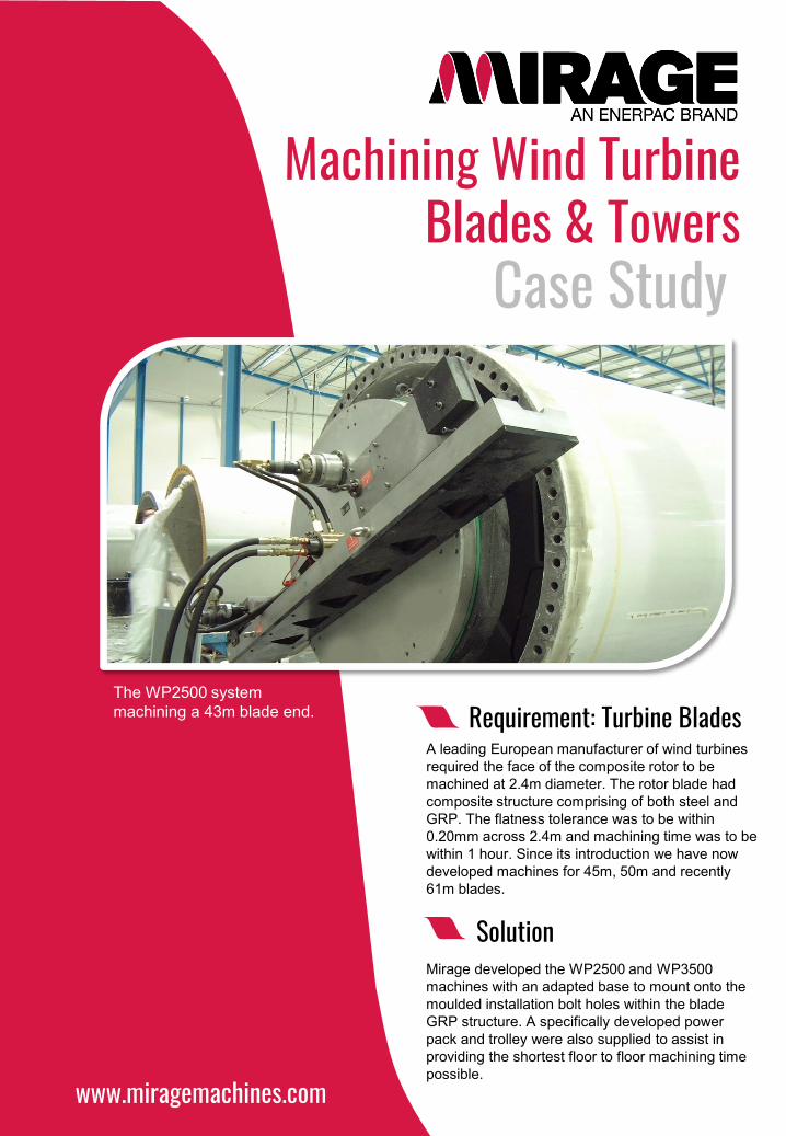
A leading European manufacturer of wind turbines required the face of the composite rotor to be machined at 2.4m diameter. The rotor blade had composite structure comprising of both steel and GRP. The flatness tolerance was to be within 0.20mm across 2.4m and machining time was to be within 1 hour. Since its introduction we have now developed machines for 45m, 50m and recently 61m blades.
Requirement: Turbine Blades
Mirage developed the WP2500 and WP3500 machines with an adapted base to mount onto the moulded installation bolt holes within the blade GRP structure. A specifically developed power pack and trolley were also supplied to assist in providing the shortest floor to floor machining time possible.
Solution
The WP2500 system machining a 43m blade end.
CASE STUDYThe machine is mounted using the special base to the 3 mounting points or through our patented hydraulic chuck allowing both the structure and machine to remain in it’s “free state” to get the best accuracy from the structure and machine possible.
The high spots on the flange are then recorded and depth of cut set with the digital scale. The machine is fitted with a 125mm face mill and machining commences at 400 mm/min giving a rotation time of 20 mins.
Method
More recently a new fast mount hydraulic clamping system has been developed – considerable reducing the reduce machine setting time.
Floor to floor machining times of 30 minutes are now possible and they have been used in the production of over 10,000 blades
Outcome
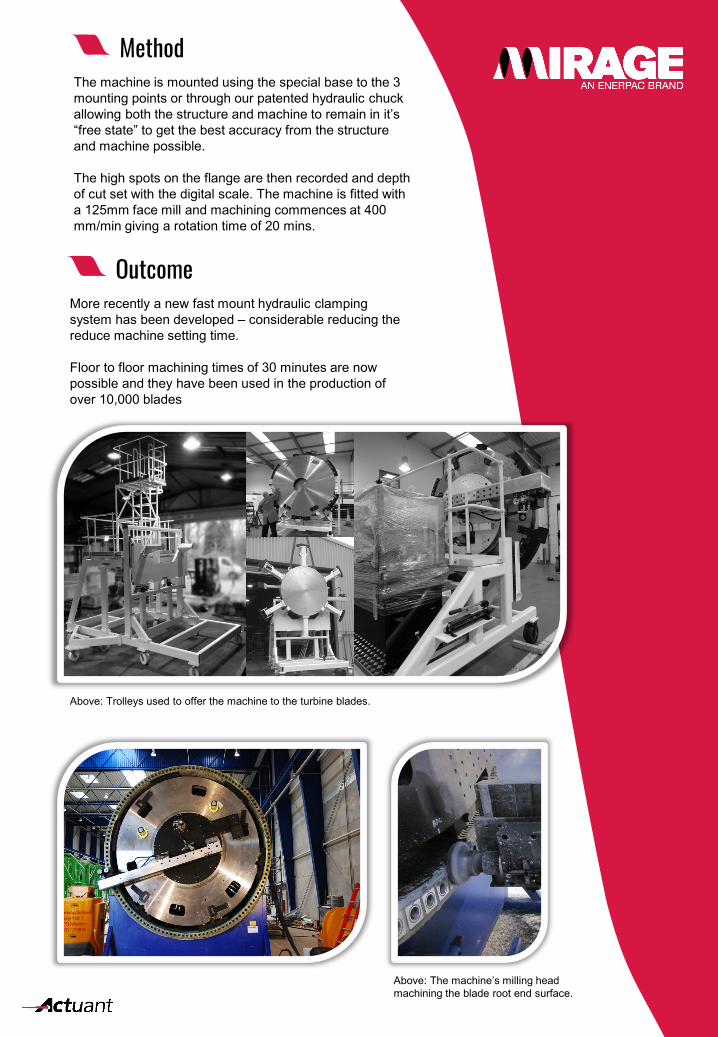
Above: Trolleys used to offer the machine to the turbine blades.
Above: The machine’s milling head machining the blade root end surface.
CASE STUDY
A leading Australian wind tower manufacturer required the end flange of the tower to be machined within 1 hour and within a flatness tolerance of 0.15mm at 2.7m diameter. The fabrication required the WP4300 to clamp into the tower and machine the flange.
Requirement: Machining Wind Turbine Tower Flanges
Mirage provided the WP4300 with a strengthened base used to mount into the tower fabrication and locked in place using an eight jaw chuck system.
The machine included rotational drive and milling spindle to enable orbital milling capability and orbital scroll milling.
The machine is mounted using the eight jaw chucking system with four off having an adjusting feature built in to allow fast easy levelling. Four additional jaws are used to provide rigidity and the machine has a hydraulic rotary distributor to enable correct hose orientation.
The machine is mounted to the tower fabrication locked in place, levelled and then machining can commence..
Solution
High spots can now be removed locally, and the customer is able to complete 3 flanges per day - saving of over 80% on previous methods.
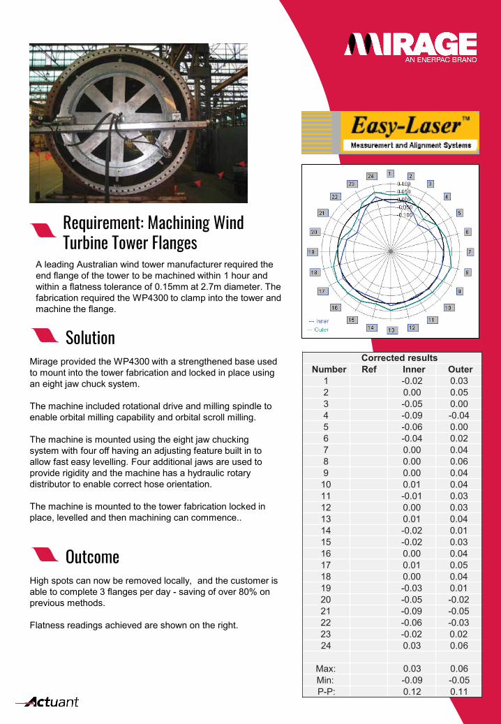
Flatness readings achieved are shown on the right.
Outcome
Corrected resultsNumber Ref Inner Outer
1 -0.02 0.032 0.00 0.053 -0.05 0.004 -0.09 -0.045 -0.06 0.006 -0.04 0.027 0.00 0.048 0.00 0.069 0.00 0.0410 0.01 0.0411 -0.01 0.0312 0.00 0.0313 0.01 0.0414 -0.02 0.0115 -0.02 0.0316 0.00 0.0417 0.01 0.0518 0.00 0.0419 -0.03 0.0120 -0.05 -0.0221 -0.09 -0.0522 -0.06 -0.0323 -0.02 0.0224 0.03 0.06
Max: 0.03 0.06Min: -0.09 -0.05P-P: 0.12 0.11