Machining Processes TABLE 8.7 General characteristics of machining processes.
Upload
faisal-shafiqCategory
view
105download
3
Machining processesTurning and Hole making

Types of latheLathes used in manufacturing can be classified as speed, engine, toolroom, turret, automatics, tracer, and numerical control turning centers.
Speed lathes usually have only a headstock, a tailstock, and a simple tool post mounted on a light bed. They ordinarily have only three or four speeds and are used primarily for wood turning, polishing, or metal spinning. Spindle speeds up to about 4000 rpm are common.
Special purpose latheBench lathe

Turret lathes
There are essentially eleven tooling stations, with six in the turret, four in the indexable tool post, and one in the rear tool post. The tooling is more rough in turret lathes because heavy, simultaneous cuts are often made. Tools mounted in the hex turret that are used for turning are often equipped with pressure rollers set on the opposite side of the rotating workpiece from the tool to counter the cutting forces.
Turret lathes are most economical in producing lots too large for engine lathes but too small for automatic screw machines or automatic lathes. In recent years much of this work has been assumed by numerical control lathes or turning centers.

Turret lathes


Close-up view of a Swiss-type screw machine, showing
the tooling and radial tool sides, actuated by rocker arms
controlled by a disk cam, shown in lower left.
On the Swiss-type automatic screw machine, the cutting tools are held and moved in radial slides (Figure). Disk cams move the tools into cutting position and provide feed into the work in a radial direction only; they provide any required longitudinal feed by reciprocating the headstock. are equipped with a transfer or “picking” attachment. This device picks up the workpiecefrom the spindle as it is cut off and carries it to a position where a secondary operation is performed by a small, auxiliary power head.

Chucking Machine• Uses chuck in its spindle to hold workpart
• Parts cannot be mounted between centers
• Cutting tool actions controlled automatically
• Operator’s job: to load and unload parts
• Applications: short, light-weight parts
Bar Machine• Similar to chucking machine except collet replaces chuck,
permitting long bar stock to be fed through headstock
• At the end of the machining cycle, a cutoff operation separates the new part
• Highly automated (the term automatic bar machine is often used)
• Applications: high production of rotational parts

When several different operations on a lathe are
performed repeatedly in sequence, the time required
for changing and setting tools may constitute as much
as 50% of the total cycle time. Quick-change tool
holders (Figure 22-18) are used to reduce manual
tool-changing time. The individual tools, preset in their
holders, can be interchanged in the special tool post
in a few seconds. With some systems, a second tool
may be set in the tool post while a cut is being made
with the first tool and can then be brought into proper
position by rotating the post.
In lathe work, the nose of the tool should be set
exactly at the same height as the axis of rotation of
the work. However, because any setting below the
axis causes the work to tend to “climb” up on the tool,
most machinists set their tools a few thousandths of
an inch above the axis, except for cutoff, threading,and some facing operations.
Quick-change tool holders


FORM TOOLSForm tools are made by grinding the inverse of the desired work contour into a block of HSS or tool steel. A threading tool is often a form tool. Although form tools are relatively expensive to manufacture, it is possible to machine a fairly complex surface with a single inward feeding of one tool. For mass-production work, adjustable form tools of either flat or rotary types, such as are shown in Figure 22-19, are used. These are expensive to make initially but can be resharpened by merely grinding a small amount off the face and then raising or rotating the cutting edge to the correct position.
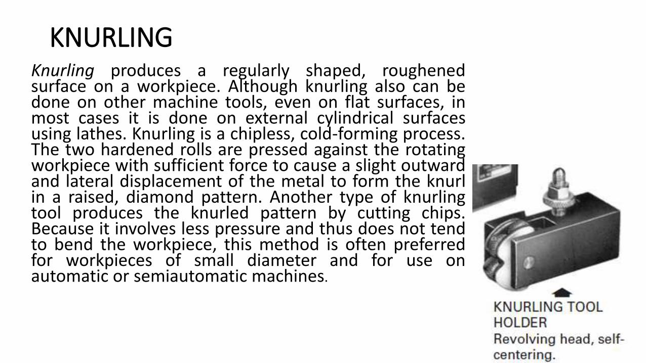
KNURLINGKnurling produces a regularly shaped, roughenedsurface on a workpiece. Although knurling also can bedone on other machine tools, even on flat surfaces, inmost cases it is done on external cylindrical surfacesusing lathes. Knurling is a chipless, cold-forming process.The two hardened rolls are pressed against the rotatingworkpiece with sufficient force to cause a slight outwardand lateral displacement of the metal to form the knurlin a raised, diamond pattern. Another type of knurlingtool produces the knurled pattern by cutting chips.Because it involves less pressure and thus does not tendto bend the workpiece, this method is often preferredfor workpieces of small diameter and for use onautomatic or semiautomatic machines.


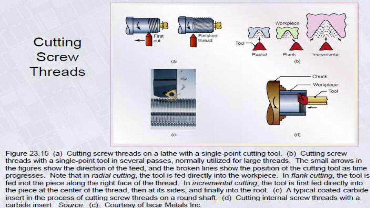
Threading
Pointed form tool is fed linearly across surface of rotating workpartparallel to axis of rotation at a large feed rate, thus creating threads

Drilling
In manufacturing it is probable that more holes are produced than any other shape, and a large proportion of these are made by drilling. Of all the machining processes performed, drilling makes up about 25%.
Most drilling is done with a tool having two cutting edges, or lips, as shown inFigure 23-1.This is a twist drill, the most common drill geometry. The cutting edgesare at the end of a relatively flexible tool. Cutting action takes place inside theworkpiece. The only exit for the chips is the hole that is mostly filled by the drill.Friction between the margin and the hole wall produces heat that is additional tothat due to chip formation. The counterflow of the chips in the flutes makeslubrication and cooling difficult

Drilling
The process of drilling creates two chips. A conventional two-flute drill, with drill of diameter D, has two principal cutting edges rotating at an rpm rate of N and feeding axially. The rpm of the drill is established by the selected cutting velocity or cutting speed with V in surface feet per minute and D in inches (mm).This equation assumes that V is the cutting speed at the outer corner of the cutting lip
The feed, fr, is given in inches per revolution. The depth ofcut in drilling is equal to half the feed rate, or t =fr /2

Feed and speed
The feed rate in inches per minute, fm, is frNs. The length of cut in drilling equals the depth of the hole, L, plus an allowance for approach and for the tip of drill, usually A =D/2.
In drilling, the speed and feed depend upon:
• the material being machined,
• the cutting tool material,
• and the size of drill.
For drilling, cutting time is

MRR
The metal removal rate is

Actions at drill pointThere are four major actions taking place at the point of a drill.
1. A small hole is formed by the web—chips are not cut here in the normal sense.
2. Chips are formed by the rotating lips.
3. Chips are removed from the hole by the screw action of the helical flutes.
4. The drill is guided by lands or margins that rub against the walls of the hole.
In recent years, new drill-point geometries and TiN coatings have resulted in improved hole accuracy, longer life, self-centering action, and increased feed-rate capabilities. However, the great majority of drills manufactured are twist drills. When high-speed steel (HSS) drills wear out, the drill can be reground to restore its original geometry. If regrinding is not done properly, the original drill geometry may be lost, and so will drill accuracy and precision. Drill performance also depends on the drilling machine tool, the workholding device, the drill holder, and the surface of the workpiece. Poor surface conditions (sand pockets and/or chilled hard spots on castings, or hard oxide scale on hot-rolled metal) can accelerate early tool failure and degrade the hole-drilling process.

TYPES OF DRILLS
The most common types of drills are twist drills. These have three basic parts: the body,
the point, and the shank, shown in Figures 23-1 and 23-2. The body contains two or
more spiral or helical grooves, called flutes, separated by lands. To reduce the friction
between the drill and the hole, each land is reduced in diameter except at the leading
edge, leaving a narrow margin of full diameter to aid in supporting and guiding the
drill and thus aiding in obtaining an accurate hole. The lands terminate in the point, with
the leading edge of each land forming a cutting edge. The flutes serve as channels
through which the chips are withdrawn from the hole and coolant gets to the cutting
edges. Although most drills have two flutes, some, as shown in Figure 23-3, have three,
and some have only one


DRILL GEOMETRY
The principal rake angles behind the cutting edges are formed by the relation of
the flute helix angle to the work. This means that the rake angle of a drill varies along
the cutting edges (or lips), being negative close to the point and equal to the helix angle
out at the lip. Because the helix angle is built into the twist drill, the primary rake angle
cannot be changed by normal grinding. The helix angle of most drills is 24°, but drills
with larger helix angles—often more than 30°—are used for materials that can be drilled
very rapidly, resulting in a large volume of chips. Helix angles ranging from 0° to 20° are
used for soft materials, such as plastics and copper. Straight-flute drills (zero helix and
rake angles) are also used for drilling thin sheets of soft materials. It is possible to
change the rake angle adjacent to the cutting edge by a special grinding procedure
called dubbing