
MACHINING OPERATIONS AND MACHINE · PDF fileMACHINING OPERATIONS AND MACHINE TOOLS ......
72
©2002 John Wiley & Sons, Inc. M. P. Groover, “ Fundamentals of Modern Manufacturing 2/e” MACHINING OPERATIONS AND MACHINE TOOLS • Turning and Related Operations • Drilling and Related Operations • Milling • Machining Centers and Turning Centers • Other Machining Operations • High Speed Machining
Transcript of MACHINING OPERATIONS AND MACHINE · PDF fileMACHINING OPERATIONS AND MACHINE TOOLS ......
©2002 John Wiley & Sons, Inc. M. P. Groover, “Fundamentals of Modern Manufacturing 2/e”
MACHINING OPERATIONS ANDMACHINE TOOLS
•Turning and Related Operations•Drilling and Related Operations•Milling•Machining Centers and Turning Centers•Other Machining Operations•High Speed Machining
©2002 John Wiley & Sons, Inc. M. P. Groover, “Fundamentals of Modern Manufacturing 2/e”
Machining
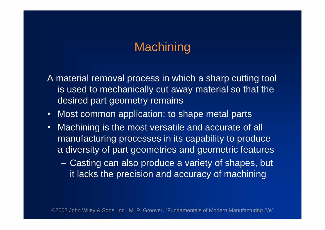
A material removal process in which a sharp cutting toolis used to mechanically cut away material so that thedesired part geometry remains
•Most common application: to shape metal parts•Machining is the most versatile and accurate of all
manufacturing processes in its capability to producea diversity of part geometries and geometric featuresCasting can also produce a variety of shapes, but
it lacks the precision and accuracy of machining

©2002 John Wiley & Sons, Inc. M. P. Groover, “Fundamentals of Modern Manufacturing 2/e”
Classification of Machined Parts1. Rotational - cylindrical or disk-like shape2. Nonrotational (also called prismatic) - block-like or
plate-like
Figure 22.1 - Machined parts are classified as: (a) rotational, or (b)nonrotational, shown here by block and flat parts

©2002 John Wiley & Sons, Inc. M. P. Groover, “Fundamentals of Modern Manufacturing 2/e”
Machining Operations and Part Geometry
Each machining operation produces a characteristic partgeometry due to two factors:1. Relative motions between the tool and the
workpart• Generating –part geometry is determined by
the feed trajectory of the cutting tool
2. Shape of the cutting tool• Forming –part geometry is created by the
shape of the cutting tool

©2002 John Wiley & Sons, Inc. M. P. Groover, “Fundamentals of Modern Manufacturing 2/e”
Figure 22.2 - Generating shape: (a) straight turning, (b) taperturning, (c) contour turning, (d) plain milling, (e) profile milling

©2002 John Wiley & Sons, Inc. M. P. Groover, “Fundamentals of Modern Manufacturing 2/e”
Figure 22.3 - Forming to create shape: (a) form turning, (b) drilling,and (c) broaching

©2002 John Wiley & Sons, Inc. M. P. Groover, “Fundamentals of Modern Manufacturing 2/e”
Figure 22.4 - Combination of forming and generating to createshape: (a) thread cutting on a lathe, and (b) slot milling
©2002 John Wiley & Sons, Inc. M. P. Groover, “Fundamentals of Modern Manufacturing 2/e”
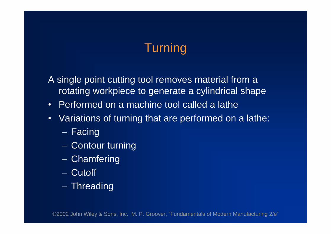
Turning
A single point cutting tool removes material from arotating workpiece to generate a cylindrical shape
•Performed on a machine tool called a lathe•Variations of turning that are performed on a lathe:
FacingContour turningChamferingCutoffThreading

©2002 John Wiley & Sons, Inc. M. P. Groover, “Fundamentals of Modern Manufacturing 2/e”
Figure 22.5 - Turning operation
©2002 John Wiley & Sons, Inc. M. P. Groover, “Fundamentals of Modern Manufacturing 2/e”
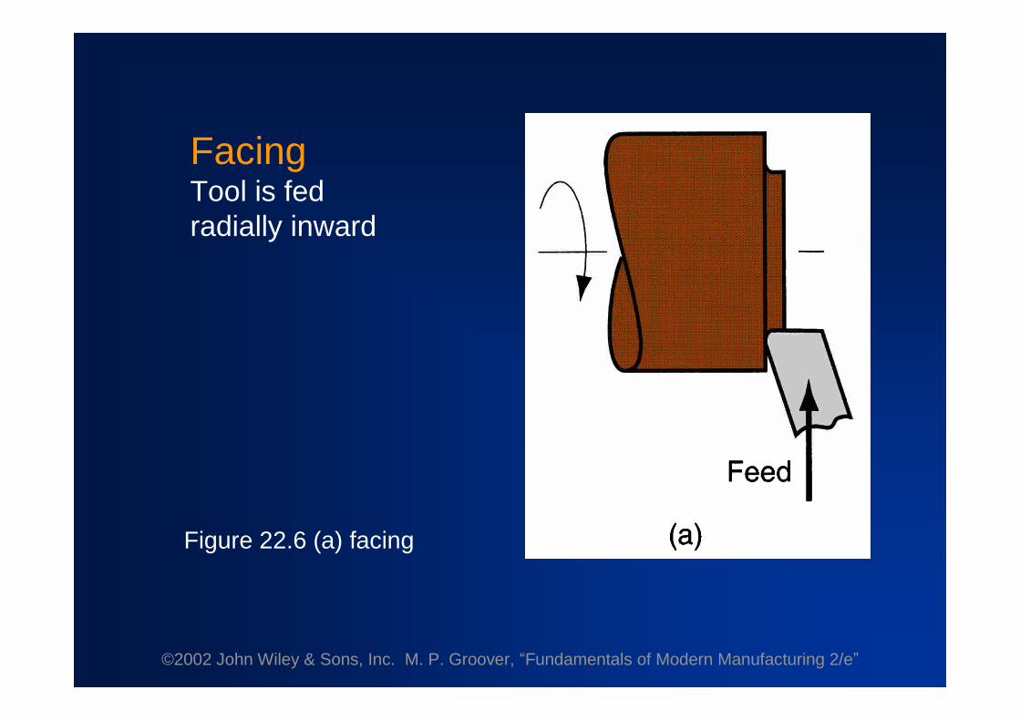
Figure 22.6 (a) facing
FacingTool is fedradially inward

©2002 John Wiley & Sons, Inc. M. P. Groover, “Fundamentals of Modern Manufacturing 2/e”
Contour TurningInstead of feeding the tool parallel to the axis of rotation,
tool follows a contour that is other than straight, thuscreating a contoured form
Figure 22.6 (c) contour turning
©2002 John Wiley & Sons, Inc. M. P. Groover, “Fundamentals of Modern Manufacturing 2/e”
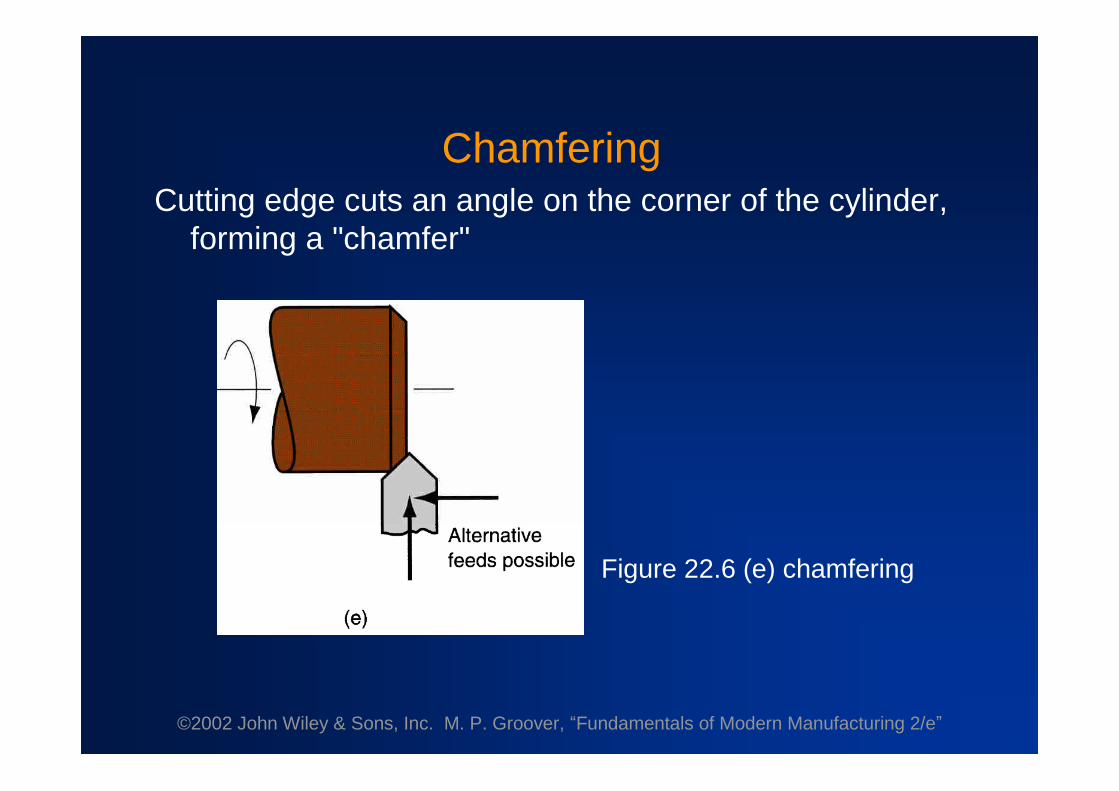
ChamferingCutting edge cuts an angle on the corner of the cylinder,
forming a "chamfer"
Figure 22.6 (e) chamfering

©2002 John Wiley & Sons, Inc. M. P. Groover, “Fundamentals of Modern Manufacturing 2/e”
CutoffTool is fed radially into rotating work at some location to
cut off end of part
Figure 22.6 (f) cutoff
©2002 John Wiley & Sons, Inc. M. P. Groover, “Fundamentals of Modern Manufacturing 2/e”
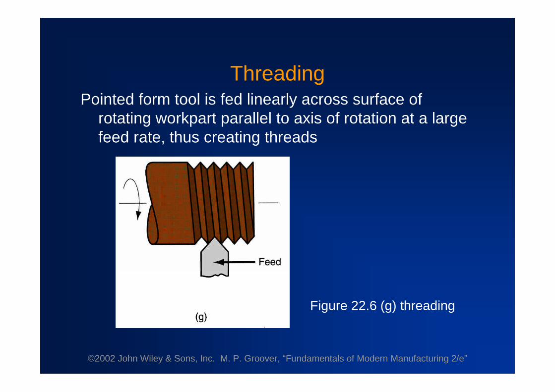
ThreadingPointed form tool is fed linearly across surface of
rotating workpart parallel to axis of rotation at a largefeed rate, thus creating threads
Figure 22.6 (g) threading

©2002 John Wiley & Sons, Inc. M. P. Groover, “Fundamentals of Modern Manufacturing 2/e”
Figure 22.7Diagram ofan enginelathe,showing itsprincipalcomponents

©2002 John Wiley & Sons, Inc. M. P. Groover, “Fundamentals of Modern Manufacturing 2/e”
Methods of Holding the Work in a Lathe
•Holding the work between centers•Chuck•Collet•Face plate

©2002 John Wiley & Sons, Inc. M. P. Groover, “Fundamentals of Modern Manufacturing 2/e”
Holding the Work Between Centers
Figure 22.8 (a) mounting the work between centers using a "dog”

©2002 John Wiley & Sons, Inc. M. P. Groover, “Fundamentals of Modern Manufacturing 2/e”
Chuck
Figure 22.8 (b) three-jaw chuck

©2002 John Wiley & Sons, Inc. M. P. Groover, “Fundamentals of Modern Manufacturing 2/e”
Collet
Figure 22.8 (c) collet

©2002 John Wiley & Sons, Inc. M. P. Groover, “Fundamentals of Modern Manufacturing 2/e”
Face Plate
Figure 22.8 (d) face plate for non-cylindrical workparts

©2002 John Wiley & Sons, Inc. M. P. Groover, “Fundamentals of Modern Manufacturing 2/e”
Turret Lathe
Tailstock replaced by “turret”that holds up to six tools•Tools rapidly brought into action by indexing the
turret•Tool post replaced by four-sided turret to index four
tools•Applications: high production work that requires a
sequence of cuts on the part

©2002 John Wiley & Sons, Inc. M. P. Groover, “Fundamentals of Modern Manufacturing 2/e”
Chucking Machine
•Uses chuck in its spindle to hold workpart•No tailstock, so parts cannot be mounted between
centers•Cutting tool actions controlled automatically•Operator’s job: to load and unload parts•Applications: short, light-weight parts
©2002 John Wiley & Sons, Inc. M. P. Groover, “Fundamentals of Modern Manufacturing 2/e”
Bar Machine
•Similar to chucking machine except collet replaceschuck, permitting long bar stock to be fed throughheadstock
•At the end of the machining cycle, a cutoff operationseparates the new part
•Highly automated (the term automatic bar machine isoften used)
•Applications: high production of rotational parts
©2002 John Wiley & Sons, Inc. M. P. Groover, “Fundamentals of Modern Manufacturing 2/e”
Automatic Screw Machine
•Same as automatic bar machine but smaller•Applications: high production of screws and similar
small hardware items; hence, its name

©2002 John Wiley & Sons, Inc. M. P. Groover, “Fundamentals of Modern Manufacturing 2/e”
Multiple Spindle Bar Machines
•More than one spindle, so multiple parts machinedsimultaneously by multiple toolsExample: six spindle automatic bar machine works
on six parts at a time•After each machining cycle, spindles (including
collets and workbars) are indexed (rotated) to nextposition

©2002 John Wiley & Sons, Inc. M. P. Groover, “Fundamentals of Modern Manufacturing 2/e”
Figure 22.9 - (a) Part produced on a six-spindle automatic barmachine; and (b) sequence of operations to produce the part: (1)
feed stock to stop, (2) turn main diameter, (3) form seconddiameter and spotface, (4) drill, (5) chamfer, and (6) cutoff

©2002 John Wiley & Sons, Inc. M. P. Groover, “Fundamentals of Modern Manufacturing 2/e”
Boring
•Difference between boring and turning:Boring is performed on the inside diameter of an
existing holeTurning is performed on the outside diameter of
an existing cylinder• In effect, boring is an internal turning operation•Boring machines
Horizontal or vertical - refers to the orientation ofthe axis of rotation of machine spindle

©2002 John Wiley & Sons, Inc. M. P. Groover, “Fundamentals of Modern Manufacturing 2/e”
Figure 22.12 - A vertical boring mill –for large, heavy workparts

©2002 John Wiley & Sons, Inc. M. P. Groover, “Fundamentals of Modern Manufacturing 2/e”
Drilling•Creates a round hole in
a workpart•Contrasts with boring
which can only enlargean existing hole
•Cutting tool called a drillor drill bit
•Customarily performedon a drill press Figure 21.3 (b) drilling
©2002 John Wiley & Sons, Inc. M. P. Groover, “Fundamentals of Modern Manufacturing 2/e”
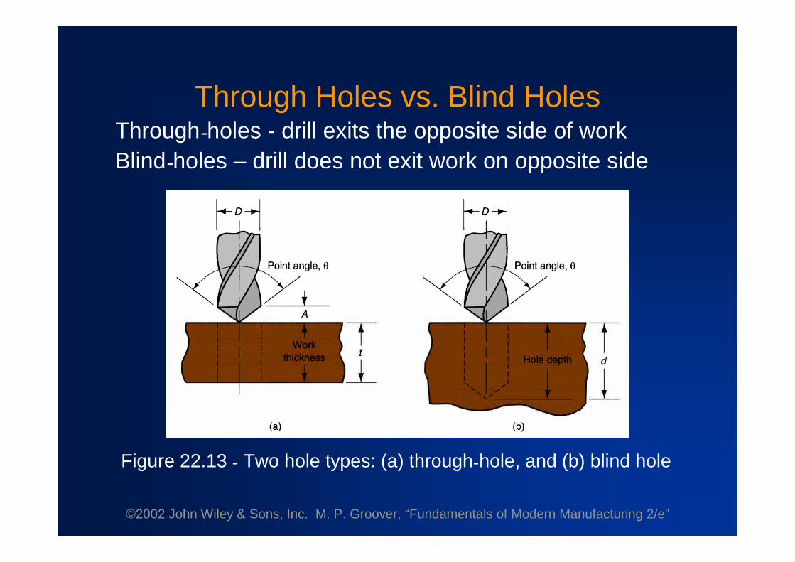
Through Holes vs. Blind HolesThrough-holes - drill exits the opposite side of workBlind-holes –drill does not exit work on opposite side
Figure 22.13 - Two hole types: (a) through-hole, and (b) blind hole

©2002 John Wiley & Sons, Inc. M. P. Groover, “Fundamentals of Modern Manufacturing 2/e”
ReamingUsed to slightly
enlarge a hole,provide bettertolerance ondiameter, andimprove surfacefinish
Figure 22.14 -Machining operationsrelated to drilling:(a) reaming
©2002 John Wiley & Sons, Inc. M. P. Groover, “Fundamentals of Modern Manufacturing 2/e”
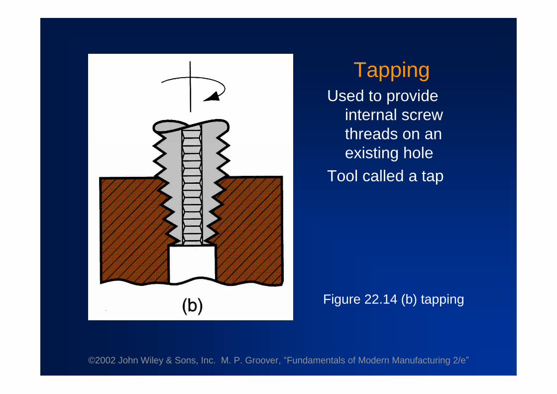
TappingUsed to provide
internal screwthreads on anexisting hole
Tool called a tap
Figure 22.14 (b) tapping

©2002 John Wiley & Sons, Inc. M. P. Groover, “Fundamentals of Modern Manufacturing 2/e”
CounterboringProvides a stepped
hole, in which alarger diameterfollows a smallerdiameter partiallyinto the hole
Figure 22.14 (c) counterboring

©2002 John Wiley & Sons, Inc. M. P. Groover, “Fundamentals of Modern Manufacturing 2/e”
Upright DrillStands on the floor
Bench DrillSimilar but smaller
and mounted ona table or bench
Figure 22.15 - Upright drill press
©2002 John Wiley & Sons, Inc. M. P. Groover, “Fundamentals of Modern Manufacturing 2/e”
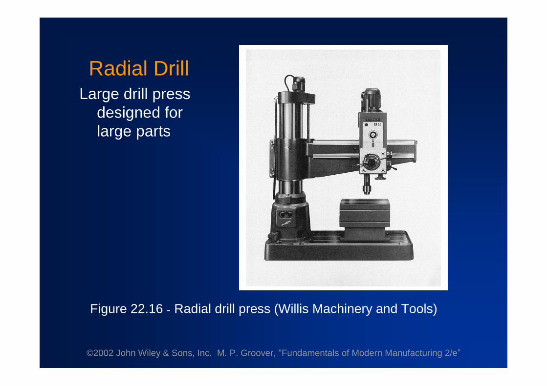
Radial DrillLarge drill press
designed forlarge parts
Figure 22.16 - Radial drill press (Willis Machinery and Tools)

©2002 John Wiley & Sons, Inc. M. P. Groover, “Fundamentals of Modern Manufacturing 2/e”
Work Holding for Drill Presses
•Workpart can be clamped in a vise, fixture, or jigVise - general purpose workholder with two jawsFixture - workholding device that is usually
custom-designed for the particular workpartDrill jig –similar to fixture but also provides a
means of guiding the tool during drilling

©2002 John Wiley & Sons, Inc. M. P. Groover, “Fundamentals of Modern Manufacturing 2/e”
Milling
Machining operation in which work is fed past a rotatingtool with multiple cutting edges
•Axis of tool rotation is perpendicular to feed direction•Creates a planar surface; other geometries possible
either by cutter path or shape•Other factors and terms:
Milling is an interrupted cutting operationCutting tool called a milling cutter, cutting edges
called "teeth"Machine tool called a milling machine

©2002 John Wiley & Sons, Inc. M. P. Groover, “Fundamentals of Modern Manufacturing 2/e”
Figure 21.3 - Two forms of milling:(a) peripheral milling, and (b) face milling

©2002 John Wiley & Sons, Inc. M. P. Groover, “Fundamentals of Modern Manufacturing 2/e”
Peripheral Milling vs. Face Milling
•Peripheral millingCutter axis is parallel to surface being machinedCutting edges on outside periphery of cutter
•Face millingCutter axis is perpendicular to surface being milledCutting edges on both the end and outside
periphery of the cutter

©2002 John Wiley & Sons, Inc. M. P. Groover, “Fundamentals of Modern Manufacturing 2/e”
Slab MillingThe basic form of peripheral milling in which the cutter
width extends beyond the workpiece on both sides
Figure 22.18(a) slab milling

©2002 John Wiley & Sons, Inc. M. P. Groover, “Fundamentals of Modern Manufacturing 2/e”
Slotting•Width of cutter is less than workpiece width, creating
a slot in the work
Figure 22.18(b) slotting

©2002 John Wiley & Sons, Inc. M. P. Groover, “Fundamentals of Modern Manufacturing 2/e”
ConventionalFace Milling
Cutter overhangs workon both sides
Figure 22.20(a) conventional face milling

©2002 John Wiley & Sons, Inc. M. P. Groover, “Fundamentals of Modern Manufacturing 2/e”
End MillingCutter diameter is less
than work width, soa slot is cut into part
Figure 22.20 - (c) end milling

©2002 John Wiley & Sons, Inc. M. P. Groover, “Fundamentals of Modern Manufacturing 2/e”
Profile MillingForm of end milling
in which theoutside peripheryof a flat part iscut
Figure 22.20 (d) profile milling
©2002 John Wiley & Sons, Inc. M. P. Groover, “Fundamentals of Modern Manufacturing 2/e”
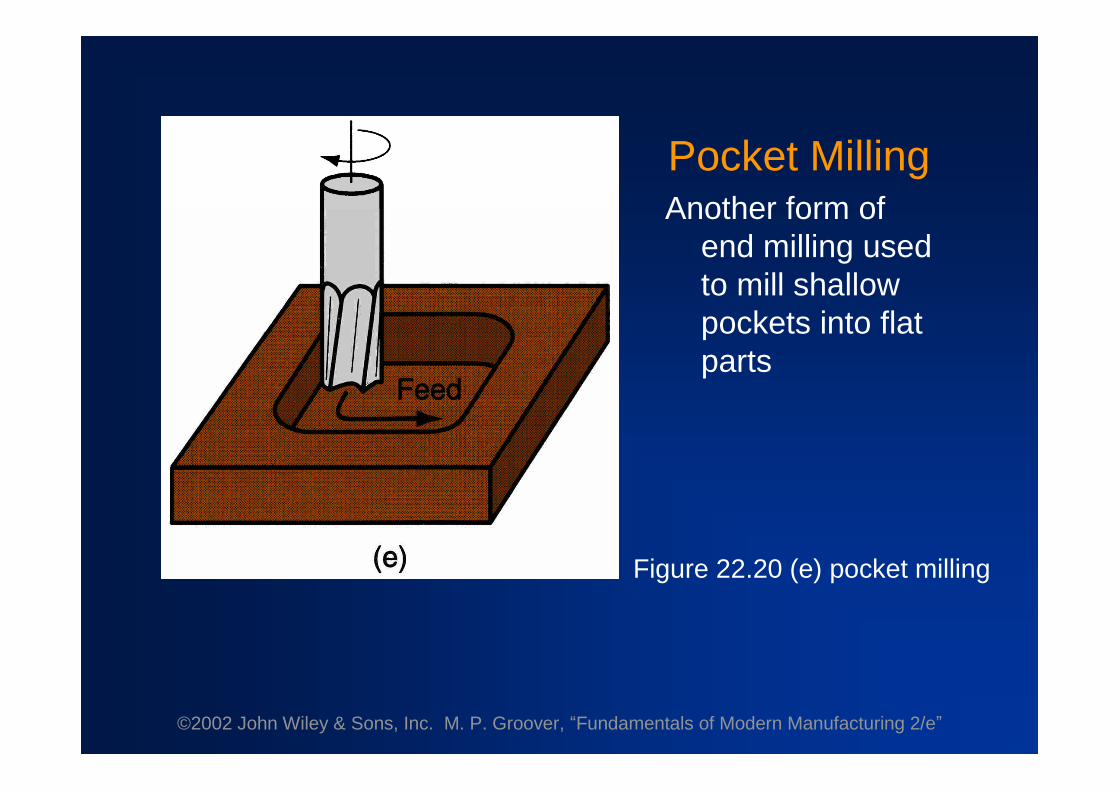
Pocket MillingAnother form of
end milling usedto mill shallowpockets into flatparts
Figure 22.20 (e) pocket milling

©2002 John Wiley & Sons, Inc. M. P. Groover, “Fundamentals of Modern Manufacturing 2/e”
Surface ContouringBall-nose cutter is fed
back and forth acrossthe work along acurvilinear path at closeintervals to create athree dimensionalsurface form
Figure 22.20 (f) surface contouring

©2002 John Wiley & Sons, Inc. M. P. Groover, “Fundamentals of Modern Manufacturing 2/e”
Figure 22.23 (a) horizontal knee-and-column milling machine
©2002 John Wiley & Sons, Inc. M. P. Groover, “Fundamentals of Modern Manufacturing 2/e”
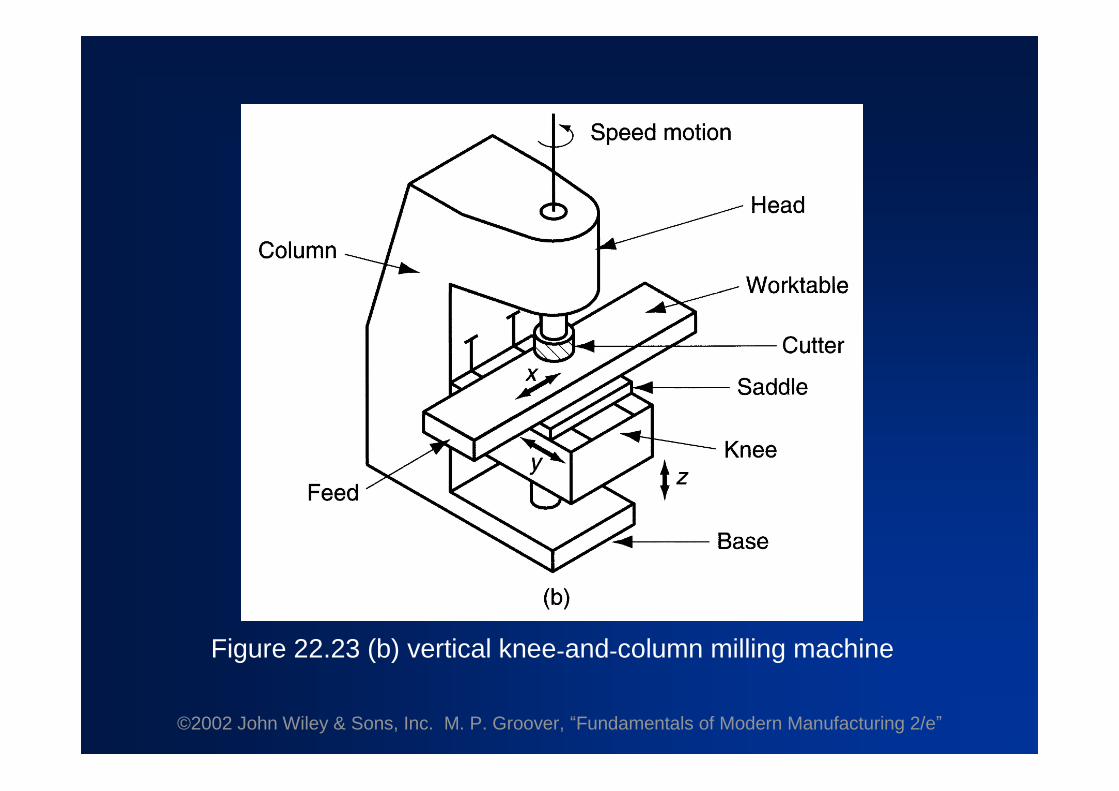
Figure 22.23 (b) vertical knee-and-column milling machine

©2002 John Wiley & Sons, Inc. M. P. Groover, “Fundamentals of Modern Manufacturing 2/e”
Figure 22.24 (b) ram type knee-and-column machine; ram canbe adjusted in and out, and toolhead can be swiveled
©2002 John Wiley & Sons, Inc. M. P. Groover, “Fundamentals of Modern Manufacturing 2/e”
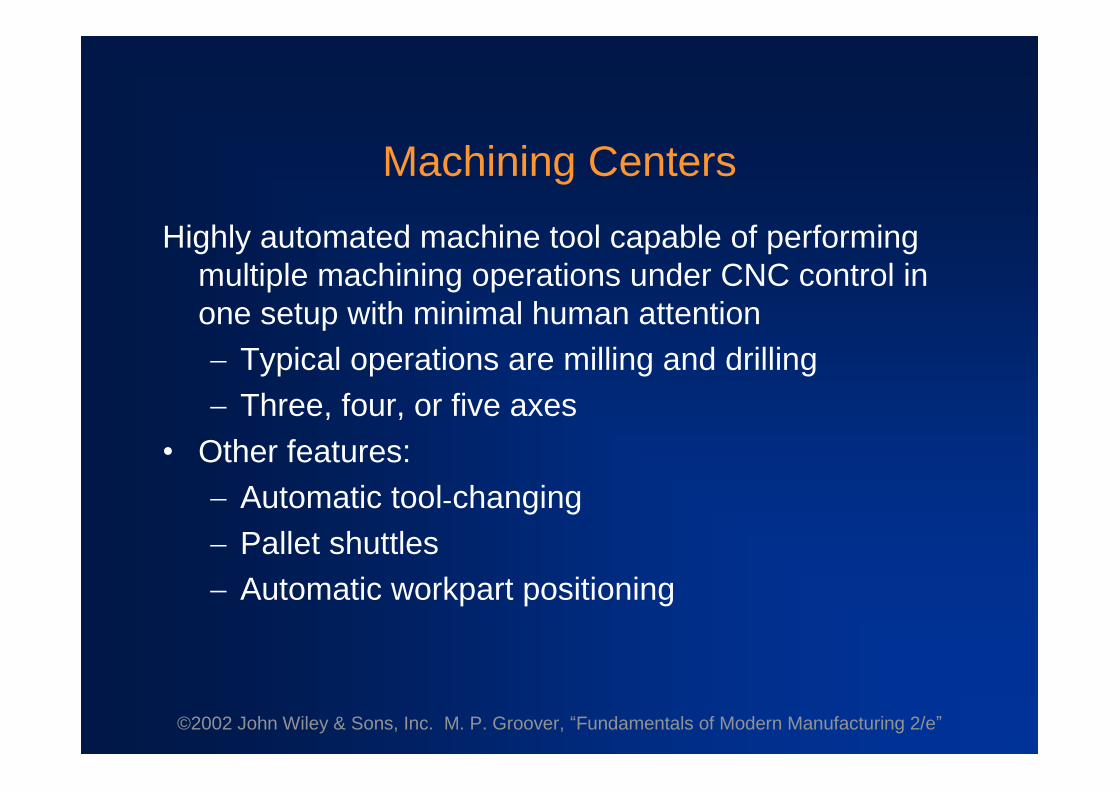
Machining Centers
Highly automated machine tool capable of performingmultiple machining operations under CNC control inone setup with minimal human attentionTypical operations are milling and drillingThree, four, or five axes
•Other features:Automatic tool-changingPallet shuttlesAutomatic workpart positioning

©2002 John Wiley & Sons, Inc. M. P. Groover, “Fundamentals of Modern Manufacturing 2/e”
Figure 22.26 - Universal machining center (Cincinnati Milacron);highly automated, capable of multiple machining operations under
computer control in one setup with minimal human attention
©2002 John Wiley & Sons, Inc. M. P. Groover, “Fundamentals of Modern Manufacturing 2/e”
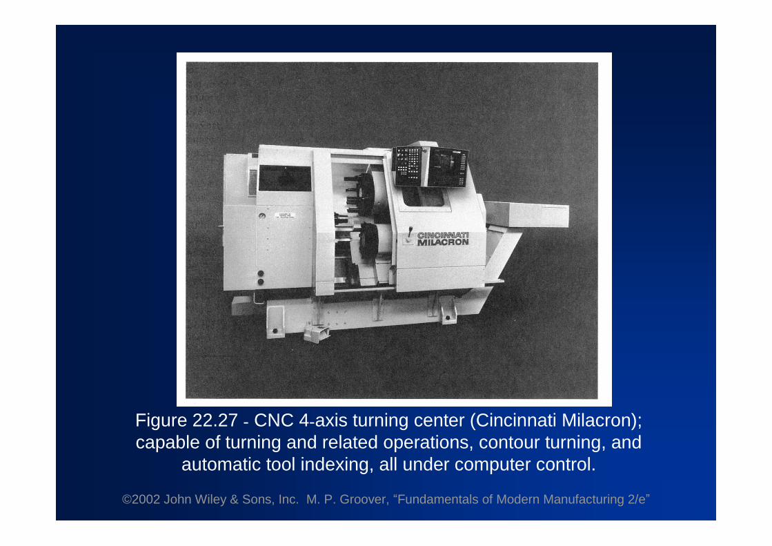
Figure 22.27 - CNC 4-axis turning center (Cincinnati Milacron);capable of turning and related operations, contour turning, and
automatic tool indexing, all under computer control.

©2002 John Wiley & Sons, Inc. M. P. Groover, “Fundamentals of Modern Manufacturing 2/e”
Mill-Turn Centers
Highly automated machine tool that can perform turning,milling, and drilling operations on a workpart
•General configuration of a turning center•Can position a cylindrical workpart at a specified
angle so a rotating cutting tool (e.g., milling cutter)can machine features into outside surface of partA conventional turning center cannot stop
workpart at a defined angular position and doesnot possess rotating tool spindles

©2002 John Wiley & Sons, Inc. M. P. Groover, “Fundamentals of Modern Manufacturing 2/e”
Figure 22.28 - Operation of a mill-turn center: (a) example part withturned, milled, and drilled surfaces; and (b) sequence of
operations on a mill-turn center: (1) turn second diameter,(2) mill flat with part in programmed angular position, (3) drill hole
with part in same programmed position, and (4) cutoff

©2002 John Wiley & Sons, Inc. M. P. Groover, “Fundamentals of Modern Manufacturing 2/e”
Shaping and Planing•Similar operations•Both use a single point cutting tool moved linearly
relative to the workpart
Figure 22.29 - (a) Shaping, and (b) planing

©2002 John Wiley & Sons, Inc. M. P. Groover, “Fundamentals of Modern Manufacturing 2/e”
Shaping and Planing
•A straight, flat surface is created in both operations• Interrupted cutting
Subjects tool to impact loading when enteringwork
•Low cutting speeds due to start-and-stop motion•Usual tooling: single point high speed steel tools

©2002 John Wiley & Sons, Inc. M. P. Groover, “Fundamentals of Modern Manufacturing 2/e”
Figure 22.30 - Components of a shaper

©2002 John Wiley & Sons, Inc. M. P. Groover, “Fundamentals of Modern Manufacturing 2/e”
Figure 22.31 - Open side planer

©2002 John Wiley & Sons, Inc. M. P. Groover, “Fundamentals of Modern Manufacturing 2/e”
Broaching•Moves a multiple tooth cutting tool linearly relative to
work in direction of tool axis
Figure 22.33 - The broaching operation
©2002 John Wiley & Sons, Inc. M. P. Groover, “Fundamentals of Modern Manufacturing 2/e”
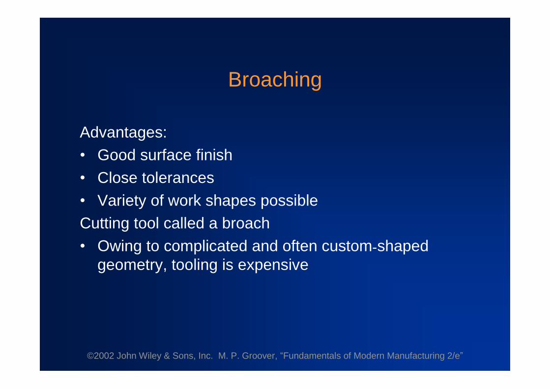
Broaching
Advantages:•Good surface finish•Close tolerances•Variety of work shapes possibleCutting tool called a broach•Owing to complicated and often custom-shaped
geometry, tooling is expensive

©2002 John Wiley & Sons, Inc. M. P. Groover, “Fundamentals of Modern Manufacturing 2/e”
Internal Broaching•Performed on internal surface of a hole•A starting hole must be present in the part to insert
broach at beginning of stroke
Figure 22.34 - Work shapes that can be cut by internal broaching;cross-hatching indicates the surfaces broached

©2002 John Wiley & Sons, Inc. M. P. Groover, “Fundamentals of Modern Manufacturing 2/e”
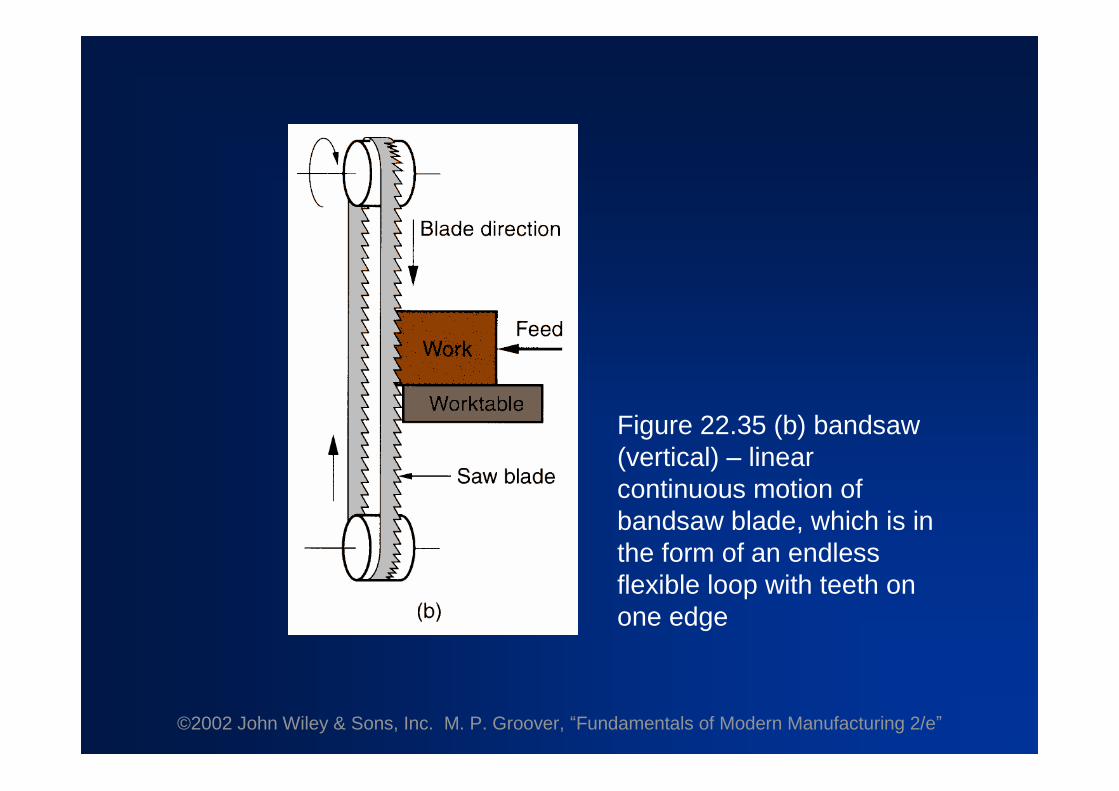
Sawing
•Cuts narrow slit in work by a tool consisting of aseries of narrowly spaced teeth
•Tool called a saw blade•Typical functions:
Separate a workpart into two piecesCut off unwanted portions of part

©2002 John Wiley & Sons, Inc. M. P. Groover, “Fundamentals of Modern Manufacturing 2/e”
Figure 22.35 (a) power hacksaw –linear reciprocating motionof hacksaw blade against work
©2002 John Wiley & Sons, Inc. M. P. Groover, “Fundamentals of Modern Manufacturing 2/e”
Figure 22.35 (b) bandsaw(vertical) –linearcontinuous motion ofbandsaw blade, which is inthe form of an endlessflexible loop with teeth onone edge

©2002 John Wiley & Sons, Inc. M. P. Groover, “Fundamentals of Modern Manufacturing 2/e”
Figure 22.35 (c) circular saw –rotating saw blade providescontinuous motion of tool past workpart
©2002 John Wiley & Sons, Inc. M. P. Groover, “Fundamentals of Modern Manufacturing 2/e”
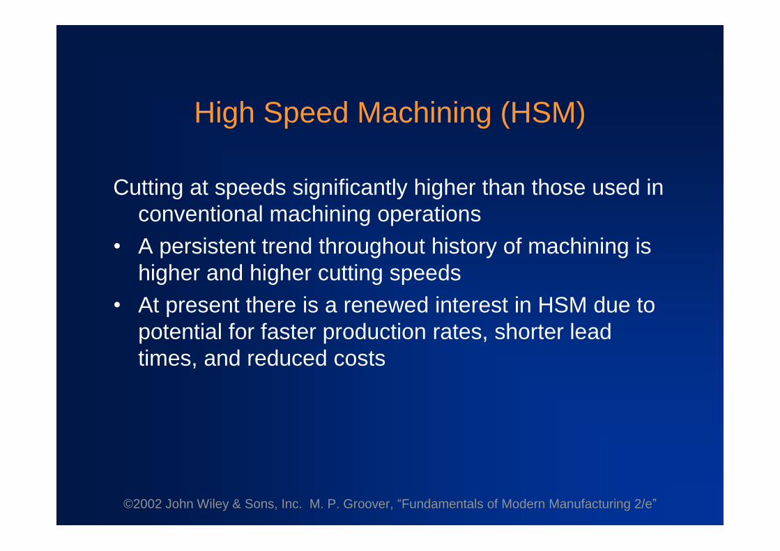
High Speed Machining (HSM)
Cutting at speeds significantly higher than those used inconventional machining operations
•A persistent trend throughout history of machining ishigher and higher cutting speeds
•At present there is a renewed interest in HSM due topotential for faster production rates, shorter leadtimes, and reduced costs

©2002 John Wiley & Sons, Inc. M. P. Groover, “Fundamentals of Modern Manufacturing 2/e”
High Speed Machining
Comparison of conventional vs. high speed machining
ft/minm/minft/minm/min
Source: Kennametal Inc.
1200360700210Steel, alloy
3000900800250Cast iron, ductile
400012001200360Cast iron, soft
12,000+3600+2000+600+Aluminum
High speedConventional speedWork material
Indexable tools (face mills)

©2002 John Wiley & Sons, Inc. M. P. Groover, “Fundamentals of Modern Manufacturing 2/e”
Other HSM Definitions –DN Ratio
DN ratio = bearing bore diameter (mm) multiplied bymaximum spindle speed (rev/min)
•For high speed machining, typical DN ratio isbetween 500,000 and 1,000,000
•Allows larger diameter bearings to fall within HSMrange, even though they operate at lower rotationalspeeds than smaller bearings

©2002 John Wiley & Sons, Inc. M. P. Groover, “Fundamentals of Modern Manufacturing 2/e”
Other HSM Definitions –HP/RPM Ratio
hp/rpm ratio = ratio of horsepower to maximum spindlespeed
•Conventional machine tools usually have a higherhp/rpm ratio than those equipped for HSM
•Dividing line between conventional machining andHSM is around 0.005 hp/rpm
•Thus, HSM includes 15 hp spindles that can rotate at30,000 rpm (0.0005 hp/rpm)
©2002 John Wiley & Sons, Inc. M. P. Groover, “Fundamentals of Modern Manufacturing 2/e”
Other HSM Definitions
•Emphasize:Higher production ratesShorter lead timesRather than functions of spindle speed
• Important non-cutting factors:Rapid traverse speedsAutomatic tool changes

©2002 John Wiley & Sons, Inc. M. P. Groover, “Fundamentals of Modern Manufacturing 2/e”
Requirements for High Speed Machining
•Special bearings designed for high rpm•High feed rate capability (e.g., 50 m/min)•CNC motion controls with “look-ahead”features to
avoid “undershooting”or “overshooting”tool path•Balanced cutting tools, toolholders, and spindles to
minimize vibration•Coolant delivery systems that provide higher
pressures than conventional machining•Chip control and removal systems to cope with much
larger metal removal rates

©2002 John Wiley & Sons, Inc. M. P. Groover, “Fundamentals of Modern Manufacturing 2/e”
High Speed Machining Applications
•Aircraft industry, machining of large airframecomponents from large aluminum blocksMuch metal removal, mostly by milling
•Multiple machining operations on aluminum toproduce automotive, computer, and medicalcomponentsQuick tool changes and tool path control important
•Die and mold industryFabricating complex geometries from hard
materials