![Porsche 924 Parts[1]](https://static.fdocuments.in/doc/165x107/552775d355034616368b47f4/porsche-924-parts1.jpg)
Machine for A 924 C Industrial...
24
A 924 C Operating Weight: 59,900 - 63,600 lb Engine Output (SAE J1349) : 173 HP / 129 kW Engine Output (ISO 9249) : 175 HP / 129 kW Machine for Industrial Applications
Transcript of Machine for A 924 C Industrial...

A 924 C
Operating Weight: 59,900 - 63,600 lbEngine Output (SAE J1349): 173 HP / 129 kWEngine Output (ISO 9249): 175 HP / 129 kW
Machine for Industrial Applications
A924C_KO_11_enUS.indd 1 07.02.11 11:14

2 A 924 C Litronic Machine for Industrial Applications
Operating Weight: 59,900 - 63,600 lbEngine Output (SAE J1349): 173 HP / 129 kWEngine Output (ISO 9249): 175 HP / 129 kW
A 924 C
A924C_KO_11_enUS.indd 2 07.02.11 11:14

3A 924 C Litronic Machine for Industrial Applications
PerformanceLiebherr material handlers are designed to deliver the high-est productivity and performance. They are built to provide high lifting capacities and quick cycle times for a smooth and efficient workflow on material handling operations. A wide range of attachments and task specific configura-tions make these machines ideally suited to a wide range
of applications.
ReliabilityLiebherr hydraulic excavators are designed and built
to operate in the most extreme material handling environments. Their innovative and rugged de-
sign ensures maximum performance and longevity.
ComfortThe spacious and ergonomically designed Liebherr op-erator’s cab provides a wide view to the working area. The operator’s seat can be individually adjusted for maxi-mum comfort and all tool controls and displays have been carefully arranged for ease of operation. Air conditioning is also a standard feature that maintains a comfortable work environment during working shifts.
EconomyThe Liebherr Litronic System increases machine perfor-mance, reduces fuel consumption and minimizes service and maintenance related costs. Liebherr’s full line of ma-terial handlers ensures a machine sized to handle the task requirements for any material handling operation.
A924C_KO_11_enUS.indd 3 07.02.11 11:14

4 A 924 C Litronic Machine for Industrial Applications
Liebherr diesel engine
•Highliftingcapacities,quickcycletimes and proven reliability.
•StageIIIA/Tier3Compliant
•Speciallydevelopedforconstructionand industrial machinery operations
•Oilsupplyevenwith100%tiltangle
•Excellenttorque
A924C_KO_11_enUS.indd 4 07.02.11 11:15

5A 924 C Litronic Machine for Industrial Applications
PerformanceThe A 924 C Litronic has been designed for maximum productivity. Precisely engi-neered, the Liebherr developed and Liebherr manufactured components including the diesel engine, hydraulic pumps and motors, as well as swing gear and cylin-ders, guarantee maximum performance. This results in a high lifting capacity with fast working cycles.
Innovative solutionsMultiple Attachments Liebherr can provide a machine for any material han-
dling application. A straight or angled industrial mono boom can be combined with various industrial sticks and a wide array of attachments to handle any task.
High Lifting Capacities The efficient handling of different materials, for ex-ample, scrap, wood, sand and gravel or bulk solids, is ensured by the most efficient use of the kinemat-ics of the machine. Liebherr will assist in the design process to ensure that the proper boom, stick and attachment combination are used to maximize the ef-ficiency of the machine for the customer.
Rapid work cycles A high swing torque is achieved through the use of a priority-driven hydraulic circuit.
Performance withoutcompromise
Maximum performance and maximum forces areavailable to the operator at all times.
Regeneration system The energy-saving regeneration system integrated into the main control block quickly lowers the at-tachment.
Robust undercarriage
•Thebox-typeconstructionoftheundercarriage with securely-weld-ed supports provides a solid base, the greatest stability and a long service life in every application
•Anadditionaldozerblade can be selected
•2-rangepowershifttransmission for stepless acceleration
Litronic-System
•Increasesproductivity of the excavator
•Reducesfuelconsumption
•Reducesservicecosts and eases operation
•Allowsmaximumsensitivityand as many overlapping movements as are required
A924C_KO_11_enUS.indd 5 07.02.11 11:15

6 A 924 C Litronic Machine for Industrial Applications
Features
•High-strengthsteelplatesat highly-stressed points for the toughest requirements
•Stablestorageofattachments and cylinders
•Maximumresistance,even when lifting heavy loads
A924C_KO_11_enUS.indd 6 07.02.11 11:15
7A 924 C Litronic Machine for Industrial Applications
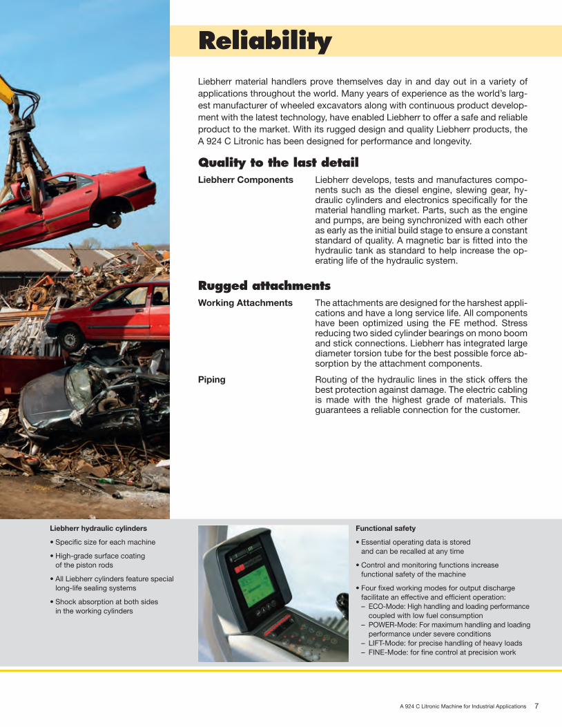
ReliabilityLiebherr material handlers prove themselves day in and day out in a variety of applications throughout the world. Many years of experience as the world’s larg-est manufacturer of wheeled excavators along with continuous product develop-ment with the latest technology, have enabled Liebherr to offer a safe and reliable product to the market. With its rugged design and quality Liebherr products, the A 924 C Litronic has been designed for performance and longevity.
Quality to the last detailLiebherr Components Liebherr develops, tests and manufactures compo-
nents such as the diesel engine, slewing gear, hy-draulic cylinders and electronics specifically for the material handling market. Parts, such as the engine and pumps, are being synchronized with each other as early as the initial build stage to ensure a constant standard of quality. A magnetic bar is fitted into the hydraulic tank as standard to help increase the op-erating life of the hydraulic system.
Rugged attachmentsWorking Attachments The attachments are designed for the harshest appli-
cations and have a long service life. All components have been optimized using the FE method. Stress reducing two sided cylinder bearings on mono boom and stick connections. Liebherr has integrated large diameter torsion tube for the best possible force ab-sorption by the attachment components.
Piping Routingofthehydrauliclinesinthestickoffersthebest protection against damage. The electric cabling is made with the highest grade of materials. This guarantees a reliable connection for the customer.
Liebherr hydraulic cylinders
•Specificsizeforeachmachine
•High-gradesurfacecoating of the piston rods
•AllLiebherrcylindersfeaturespeciallong-life sealing systems
•Shockabsorptionatbothsides in the working cylinders
Functional safety
•Essentialoperatingdataisstored and can be recalled at any time
•Controlandmonitoringfunctionsincrease functional safety of the machine
•Fourfixedworkingmodesforoutputdischarge facilitate an effective and efficient operation:
– ECO-Mode: High handling and loading performance coupled with low fuel consumption
– POWER-Mode:Formaximumhandlingandloading performance under severe conditions
– LIFT-Mode: for precise handling of heavy loads – FINE-Mode: for fine control at precision work
A924C_KO_11_enUS.indd 7 07.02.11 11:15

8 A 924 C Litronic Machine for Industrial Applications
Large-sized cab
•Adjustablesteeringcolumn
•Operator’sseat,adjustableinheight and can also be adapted to the individual weight of the operator
•Consoleswithorwithoutpos-sibility of horizontal adjustment
•Largeroofwindow
•Sunblinds
A924C_KO_11_enUS.indd 8 07.02.11 11:15
9A 924 C Litronic Machine for Industrial Applications
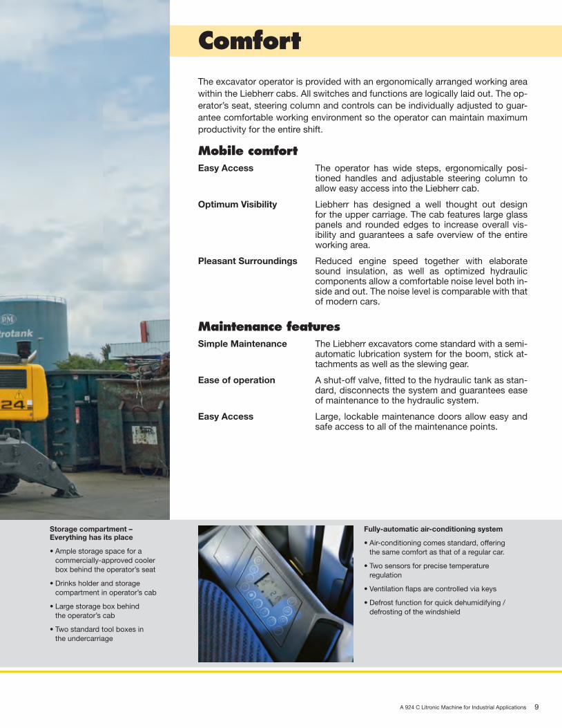
Comfort
Fully-automatic air-conditioning system
•Air-conditioningcomesstandard,offering the same comfort as that of a regular car.
•Twosensorsforprecisetemperature regulation
•Ventilationflapsarecontrolledviakeys
•Defrostfunctionforquickdehumidifying/ defrosting of the windshield
Storage compartment –Everything has its place
•Amplestoragespacefora commercially-approved cooler box behind the operator’s seat
•Drinksholderandstorage compartment in operator’s cab
•Largestorageboxbehind the operator’s cab
•Twostandardtoolboxesin the undercarriage
The excavator operator is provided with an ergonomically arranged working area within the Liebherr cabs. All switches and functions are logically laid out. The op-erator’s seat, steering column and controls can be individually adjusted to guar-antee comfortable working environment so the operator can maintain maximum productivity for the entire shift.
Mobile comfortEasy Access The operator has wide steps, ergonomically posi-
tioned handles and adjustable steering column to allow easy access into the Liebherr cab.
Optimum Visibility Liebherr has designed a well thought out design for the upper carriage. The cab features large glass panels and rounded edges to increase overall vis-ibility and guarantees a safe overview of the entire working area.
Pleasant Surroundings Reduced engine speed together with elaboratesound insulation, as well as optimized hydraulic components allow a comfortable noise level both in-side and out. The noise level is comparable with that of modern cars.
Maintenance featuresSimple Maintenance The Liebherr excavators come standard with a semi-
automatic lubrication system for the boom, stick at-tachments as well as the slewing gear.
Ease of operation A shut-off valve, fitted to the hydraulic tank as stan-dard, disconnects the system and guarantees ease of maintenance to the hydraulic system.
Easy Access Large, lockable maintenance doors allow easy and safe access to all of the maintenance points.
A924C_KO_11_enUS.indd 9 07.02.11 11:15

10 A 924 C Litronic Machine for Industrial Applications
Hydrostatic fan drive
•Acceleratedwarm-upperiod
•Guaranteedconstantoilqualityasa result of constant oil temperature
•Increasedlifeexpectancyofdrivecomponents
•Thefanonlyrunsattheoutput required, thus conserving fuel and reducing the noise level considerably
•Thermostaticcontrol
A924C_KO_11_enUS.indd 10 07.02.11 11:15
11A 924 C Litronic Machine for Industrial Applications
EconomyLiebherr offers a wide range of Material Handlers models to maximize produc-tivity in any application. Easy access to components and service points on the Liebherr Material Handlers allow for quick maintenance and minimal downtime reducing operating costs and maximizing production.
Low operating costsLiebherr Engine The A 924 C is powered by a Liebherr made engine
which is specifically designed to maximum power and performance through the cycle with maximum fuel economy. This minimizes power loss, boosts productivity and lowers fuel consumption. There-fore, the carbon footprint is minimized and per hour operating costs are lower.
Automatic Engine Idle A great feature of the Liebherr Material Handler is the Auto Engine Idle. The machine will automatically idle the engine if a hydraulic or engine function is not used over a period of time. The joysticks contain a proximity switch that once the operator is range of the joystick the engine will automatically return to operatingRPM.
Intelligent hydraulicmanagement
The state-of-the-art hydraulic system allows conver-sion of the maximum engine output into high force or speed, as required.
Hydraulically Adjustable Cab
The hydraulically adjustable cab is especially impor-tant when working with ships, barges or transload-ing material from trucks or railcars to maximize point of site to the working area.
Investment for the futureExtensive service offer Our service personnel is trained directly at the man-
ufacturing plants and endorsed by our tight-knit net-work of dealers.
High resale values Liebherr Material Handlers are designed with the highest grade materials possible providing the high-est quality, with best fuel economy. When time comes to exchange for the next Liebherr, rest assured that a Liebherr Material Handler commands the best re-sidual value in the Material Handling Industry.
Service oriented
•Engineservicepoints-suchasthe filter or capacity displays - easily to access and reach via a catwalk
•Themagnetbarinthehydraulicoiltankacts as a service indicator and increas-es the service life of the oil
•Liebherrsemi-automaticcentrallubri-cating systems for the slewing gear and main attachment components fit-ted as standard for quick and targeted maintenance
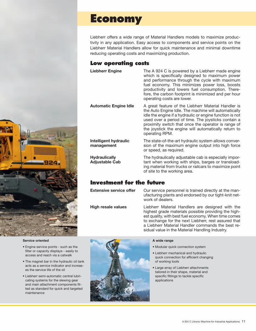
A wide range
•Modularquickconnectionsystem
•Liebherrmechanicalandhydraulicquick connection for efficient changing of working tools
•LargearrayofLiebherrattachmentstailored in their shape, material and specific fittings to tackle specific applications
A924C_KO_11_enUS.indd 11 07.02.11 11:16

12 A 924 C Litronic Machine for Industrial Applications
Technical Data
EngineRating per SAE J1349 ����������� 173 HP (129 kW) at 1,800 rpmRating per ISO 9249 ������������� 175 HP (129 kW) at 1,800 rpmModel ������������������������������� Liebherr D 934 L according to level IIIA / Tier 3Type �������������������������������� 4 cylinder in-line Bore/Stroke ������������������ 4.8/5.9 in Displacement ���������������� 427 in3
Engine operation ����������������� 4-stroke dieselunit pump system turbo-charged and after-cooled reduced emissions
Cooling system ������������������� water-cooled and integrated motor oil coolerAir cleaner ������������������������� dry-type air cleaner with pre-cleaner, primary and
safety elementsFuel tank ��������������������������� 106 galEngine idling ���������������������� sensor controlledElectrical system Voltage ����������������������� 24 V Batteries ���������������������� 2 x 135 Ah/12 V Alternator ��������������������� three phase current 28 V/80 AOption ������������������������������ Liebherr particle filter
Hydraulic SystemHydraulic pump ������������������� Liebherr, variable displacement, swash plate
double pump Max. flow ��������������������� 2 x 57 gpm Max. hydr. pressure �������� 5,076 psiHydraulic pumpregulation and control ����������� Liebherr-Synchronic-Comfort-system (LSC) with
electronic engine speed sensing regulation, pres-sure and flow compensation, load sensing and torque controlled swing drive priority
Hydraulic tank capacity ��������� 66 galHydraulic system capacity ������ max. 114 galFiltration ���������������������������� one main return filter with integrated partial micro
filtration (5 µm)Cooling system ������������������� cooler unit, consisting of radiator for engine
coolant with after-cooler core, sandwiched with cooler for hydraulic fluid and fuel with hydro-statically controlled fan drive
MODE selection ������������������ adjustment of machine performance and the hydraulics via mode selector to match job appli-cation (Note: All modes provide full max. power)
LIFT ��������������������������� for precise lifting tasks FINE ��������������������������� for precision work and lifting ECO ��������������������������� for economical operation POWER ����������������������� for max. outputSuper-Finish ����������������������� additional operator adjustable work speed func-
tion for further increased feathering. Applies to all modes and all control functions
RPM adjustment ������������������ stepless adjustment of engine output via rpmTool Control (Option) ������������ ten pre-adjustable pump flows and pres sures for
add on tools
Hydraulic ControlsPower distribution ���������������� via control valve with integrated safety valves,
simultaneous and independent operation of travel drive, swing drive and work
Control type Attachment and swing ����� proportional via joystick levers Travel ������������������������� proportional via foot pedalAdditional functions �������������� via joystick push buttons or foot pedals
Swing DriveDrive �������������������������������� swash plate motor with torque control and inte-
grated brake valveTransmission ���������������������� Liebherr compact planetary reduction gearSwing ring ������������������������� Liebherr sealed single race ball bearing swing
ring, internal teethSwing speed ���������������������� 0 – 8.0 rpm steplessSwing torque ���������������������� 54,580 lbf ftHolding brake ��������������������� wet discs (spring applied – pressure released)Option ������������������������������ pedal controlled positioning brake
Operator’s CabCab ��������������������������������� resiliently mounted, sound insulated, tinted
windows, front window stores overhead, door with sliding window
Operator’s seat ������������������� fully adjustable, shock absorbing suspension, adjustable to operator’s weight and size, 6-way adjustable Liebherr seat
Joysticks ��������������������������� integrated into adjustable seat consolesMonitoring ������������������������� menu driven query of current operating condi-
tions via the LCD display. Automatic monitoring, display, warning (acoustical and optical signal) and saving machine data, for example, engine overheating, low engine oil pressure or low hydraulic oil level
Air conditioning ������������������� standard air conditioning, combined cooler/heater, additional dust filter in fresh air/recircu-lated
Noise emissionISO 6396 ��������������������������� LpA (inside cab) = 74 dB(A)2000/14/EC ����������������������� LWA (surround noise) = 103 dB(A)
UndercarriageDrive �������������������������������� variable flow swash plate motor with automatic
brake valveTransmission ���������������������� oversized two speed power shift trans mission
with additional creeper speedTravel speed ���������������������� 0 – 1.6 mph (creeper speed off road)
0 – 3.1 mph (off road) 0 – 5.6 mph (creeper speed on road) 0 – 12.4 mph (road travel)
Axles �������������������������������� 88,185 lb excavator axles; automatic or operator controlled front axle oscillation lock
Brakes ������������������������������ steering and rigid axle with wet, mainte nance-free multi disc brakes with minimized backlash. Spring applied/pressure released parking brake inte-grated into gear box
Stabilization ����������������������� 4-point outriggers with suspended rocker arm supports
AttachmentType �������������������������������� high-strength steel plates at highly stressed
points for the toughest requirements. Complex and stable mountings of attachment and cylin-ders. Unrivalled strength, even at high loads
Hydraulic cylinders ��������������� Liebherr cylinders with special seal system. Shock absorbing
Pivots ������������������������������� sealed, low maintenanceLubrication ������������������������ Liebherr semi-automatic central lubrication
system

A 924 C Litronic Machine for Industrial Applications 13
Dimensions
ft inA 8’ 7”B 9’ B1 13’11”C 10’ 9”D 9’ E 9’ 3”H 8’ 8”K 4’ 5”L 9’ 2”M 4’ 7”Q 1’ 2”R1 14’ 4”R2 25’ 2”T1 3’ 5”T4 3’11”U4 16’ 6”Z 17’
E = Tail radius
Tires 11.00-20
Industrial-Type Straight Boom 22’4”and Industrial Stick ft in 16’ 5”* 19’ 8”*V ft in 21’ 6”* 19’ *W ft in 8’10”* 12’ 2”*X ft in 33’ 4”* 32’10”*
Industrial-Type Straight Boom 25’7”and Industrial Stick ft in 16’ 5” 19’ 8”V ft in 24’ 1” 21’ 8”*W ft in 7’10” 10’ 2”*X ft in 36’ 5” 36’ 5”*
Industrial-Type Gooseneck Boom 21’4”and Industrial Stick ft in 13’ 1” 16’ 5”V ft in 22’10” 20’ 6”W ft in 9’ 11’ X ft in 32’ 2” 32’ 4”
Industrial-Type Straight Boom 22’4”and Industrial Stick with Tipping Kinematics ft in 16’ 5”V ft in 18’ 4”W ft in 8’ 8”X ft in 33’ 2”
Dimensions are with attachment over steering axle* Attachment over digging axle for shorter transport dimensions
LU4
VX
W
DE
K
H
C
B
Q
A
B1
M T1
Z
T4
R1
R2

14 A 924 C Litronic Machine for Industrial Applications
Industrial Attachmentfor Scrap Handling with Straight Boom 22’4”
Attachment EnvelopeIndustrial-type straight boom pinned in rear bearing of boom foot bracket
1 with industrial stick 16’5”2 with industrial stick 19’8”3 with industrial stick 16’5” and grapple model 654 with industrial stick 19’8” and grapple model 65
Operating WeightOperating weight includes basic machine A 924 C litronic̀ with 4 pt. outriggers, hydr. cab elevation, 8 solid tires plus spacer rings, and industrial attachment with industrial-type straight boom 22’4”.
with grapple model 65/0.78 yd3 semi-closed tines Weightand industrial stick 16’5” 62,150 lband industrial stick 19’8” 62,400 lb
1
2
3
4
0m
0ft
123456789
51015202530
10
00
-1
-2
-3
-4
-5
-5
-10
-15
1
2
3
4
5
6
5
10
15
20
7
8
9
25
30
10
11
mft
35
12
13
40
1112
3540
-6
-7
-8
-20
-25
14
15
45
50
1314
45
A 924 C Litronic Machine for Industrial Applications 15
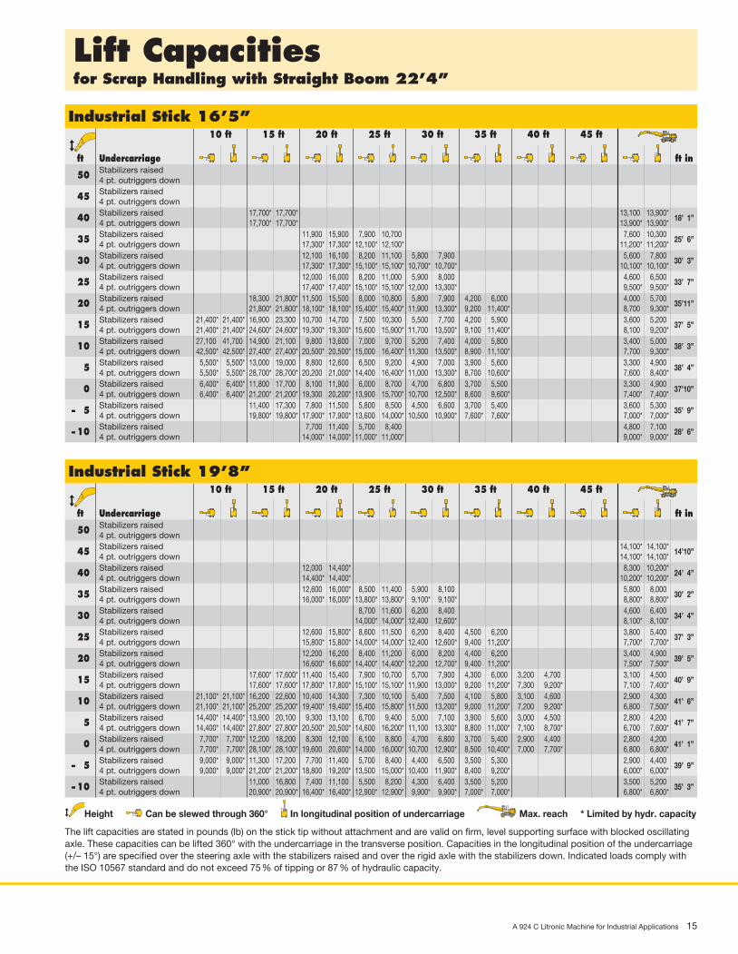
Lift Capacitiesfor Scrap Handling with Straight Boom 22’4”
Industrial Stick 16’5” 10 ft 15 ft 20 ft 25 ft 30 ft 35 ft 40 ft 45 ft
ft Undercarriage ft in Stabilizers raised 50 4 pt. outriggers down Stabilizers raised 45 4 pt. outriggers down Stabilizers raised 40 4 pt. outriggers down Stabilizers raised 35 4 pt. outriggers down Stabilizers raised 30 4 pt. outriggers down Stabilizers raised 25 4 pt. outriggers down Stabilizers raised 20 4 pt. outriggers down Stabilizers raised 15 4 pt. outriggers down Stabilizers raised 10 4 pt. outriggers down Stabilizers raised 5 4 pt. outriggers down Stabilizers raised 0 4 pt. outriggers down Stabilizers raised – 5 4 pt. outriggers down Stabilizers raised – 10 4 pt. outriggers down
17,700* 17,700* 13,100 13,900* 17,700* 17,700* 13,900* 13,900*
18’ 1”
11,900 15,900 7,900 10,700 7,600 10,300 17,300* 17,300* 12,100* 12,100* 11,200* 11,200*
25’ 6”
12,100 16,100 8,200 11,100 5,800 7,900 5,600 7,800 17,300* 17,300* 15,100* 15,100* 10,700* 10,700* 10,100* 10,100*
30’ 3”
12,000 16,000 8,200 11,000 5,900 8,000 4,600 6,500 17,400* 17,400* 15,100* 15,100* 12,000 13,300* 9,500* 9,500*
33’ 7”
18,300 21,800* 11,500 15,500 8,000 10,800 5,800 7,900 4,200 6,000 4,000 5,700 21,800* 21,800* 18,100* 18,100* 15,400* 15,400* 11,900 13,300* 9,200 11,400* 8,700 9,300*
35’11”
21,400* 21,400* 16,900 23,300 10,700 14,700 7,500 10,300 5,500 7,700 4,200 5,900 3,600 5,200 21,400* 21,400* 24,600* 24,600* 19,300* 19,300* 15,600 15,900* 11,700 13,500* 9,100 11,400* 8,100 9,200*
37’ 5”
27,100 41,700 14,900 21,100 9,800 13,600 7,000 9,700 5,200 7,400 4,000 5,800 3,400 5,000 42,500* 42,500* 27,400* 27,400* 20,500* 20,500* 15,000 16,400* 11,300 13,500* 8,900 11,100* 7,700 9,300*
38’ 3”
5,500* 5,500* 13,000 19,000 8,800 12,600 6,500 9,200 4,900 7,000 3,900 5,600 3,300 4,900 5,500* 5,500* 28,700* 28,700* 20,200 21,000* 14,400 16,400* 11,000 13,300* 8,700 10,600* 7,600 8,400*
38’ 4”
6,400* 6,400* 11,800 17,700 8,100 11,900 6,000 8,700 4,700 6,800 3,700 5,500 3,300 4,900 6,400* 6,400* 21,200* 21,200* 19,300 20,200* 13,900 15,700* 10,700 12,500* 8,600 9,600* 7,400* 7,400*
37’10”
11,400 17,300 7,800 11,500 5,800 8,500 4,500 6,600 3,700 5,400 3,600 5,300 19,800* 19,800* 17,900* 17,900* 13,600 14,000* 10,500 10,900* 7,600* 7,600* 7,000* 7,000*
35’ 9”
7,700 11,400 5,700 8,400 4,800 7,100 14,000* 14,000* 11,000* 11,000* 9,000* 9,000*
28’ 6”
Industrial Stick 19’8” 10 ft 15 ft 20 ft 25 ft 30 ft 35 ft 40 ft 45 ft
ft Undercarriage ft in Stabilizers raised 50 4 pt. outriggers down Stabilizers raised 45 4 pt. outriggers down Stabilizers raised 40 4 pt. outriggers down Stabilizers raised 35 4 pt. outriggers down Stabilizers raised 30 4 pt. outriggers down Stabilizers raised 25 4 pt. outriggers down Stabilizers raised 20 4 pt. outriggers down Stabilizers raised 15 4 pt. outriggers down Stabilizers raised 10 4 pt. outriggers down Stabilizers raised 5 4 pt. outriggers down Stabilizers raised 0 4 pt. outriggers down Stabilizers raised – 5 4 pt. outriggers down Stabilizers raised – 10 4 pt. outriggers down
14,100* 14,100* 14,100* 14,100*
14’10”
12,000 14,400* 8,300 10,200* 14,400* 14,400* 10,200* 10,200*
24’ 4”
12,600 16,000* 8,500 11,400 5,900 8,100 5,800 8,000 16,000* 16,000* 13,800* 13,800* 9,100* 9,100* 8,800* 8,800*
30’ 2”
8,700 11,600 6,200 8,400 4,600 6,400 14,000* 14,000* 12,400 12,600* 8,100* 8,100*
34’ 4”
12,600 15,800* 8,600 11,500 6,200 8,400 4,500 6,200 3,800 5,400 15,800* 15,800* 14,000* 14,000* 12,400 12,600* 9,400 11,200* 7,700* 7,700*
37’ 3”
12,200 16,200 8,400 11,200 6,000 8,200 4,400 6,200 3,400 4,900 16,600* 16,600* 14,400* 14,400* 12,200 12,700* 9,400 11,200* 7,500* 7,500*
39’ 5”
17,600* 17,600* 11,400 15,400 7,900 10,700 5,700 7,900 4,300 6,000 3,200 4,700 3,100 4,500 17,600* 17,600* 17,800* 17,800* 15,100* 15,100* 11,900 13,000* 9,200 11,200* 7,300 9,200* 7,100 7,400*
40’ 9”
21,100* 21,100* 16,200 22,600 10,400 14,300 7,300 10,100 5,400 7,500 4,100 5,800 3,100 4,600 2,900 4,300 21,100* 21,100* 25,200* 25,200* 19,400* 19,400* 15,400 15,800* 11,500 13,200* 9,000 11,200* 7,200 9,200* 6,800 7,500*
41’ 6”
14,400* 14,400* 13,900 20,100 9,300 13,100 6,700 9,400 5,000 7,100 3,900 5,600 3,000 4,500 2,800 4,200 14,400* 14,400* 27,800* 27,800* 20,500* 20,500* 14,600 16,200* 11,100 13,300* 8,800 11,000* 7,100 8,700* 6,700 7,600*
41’ 7”
7,700* 7,700* 12,200 18,200 8,300 12,100 6,100 8,800 4,700 6,800 3,700 5,400 2,900 4,400 2,800 4,200 7,700* 7,700* 28,100* 28,100* 19,600 20,600* 14,000 16,000* 10,700 12,900* 8,500 10,400* 7,000 7,700* 6,800 6,800*
41’ 1”
9,000* 9,000* 11,300 17,200 7,700 11,400 5,700 8,400 4,400 6,500 3,500 5,300 2,900 4,400 9,000* 9,000* 21,200* 21,200* 18,800 19,200* 13,500 15,000* 10,400 11,900* 8,400 9,200* 6,000* 6,000*
39’ 9”
11,000 16,800 7,400 11,100 5,500 8,200 4,300 6,400 3,500 5,200 3,500 5,200 20,900* 20,900* 16,400* 16,400* 12,900* 12,900* 9,900* 9,900* 7,000* 7,000* 6,800* 6,800*
35’ 3”
Height Can be slewed through 360° In longitudinal position of undercarriage Max. reach * Limited by hydr. capacity
The lift capacities are stated in pounds (lb) on the stick tip without attachment and are valid on firm, level supporting surface with blocked oscillating axle. These capacities can be lifted 360° with the undercarriage in the transverse position. Capacities in the longitudinal position of the undercarriage (+/– 15°) are specified over the steering axle with the stabilizers raised and over the rigid axle with the stabilizers down. Indicated loads comply with the ISO 10567 standard and do not exceed 75 % of tipping or 87 % of hydraulic capacity.

16 A 924 C Litronic Machine for Industrial Applications
Industrial Attachmentfor Scrap Handling with Straight Boom 25’7”
Attachment EnvelopeIndustrial-type straight boom pinned in rear bearing of boom foot bracket
1 with industrial stick 16’5”2 with industrial stick 19’8”3 with industrial stick 16’5” and grapple model 654 with industrial stick 19’8” and grapple model 65
Operating WeightOperating weight includes basic machine A 924 C litronic̀ with 4 pt. outriggers, hydr. cab elevation, 8 solid tires plus spacer rings, and industrial attachment with industrial-type straight boom 25’7”.
with grapple model 65/0.78 yd3 semi-closed tines Weightand industrial stick 16’6” 62,600 lband industrial stick 19’8” 63,050 lb
1
2
3
4
0m
0ft
123456789
51015202530
10
00
-1
-2
-3
-4
-5
-5
-10
-15
1
2
3
4
5
6
5
10
15
20
7
8
9
25
30
10
11
mft
35
12
1340
1112
3540
-6
-7
-8
-20
-25
14
15
45
50
1314
45
16
15
50
A 924 C Litronic Machine for Industrial Applications 17
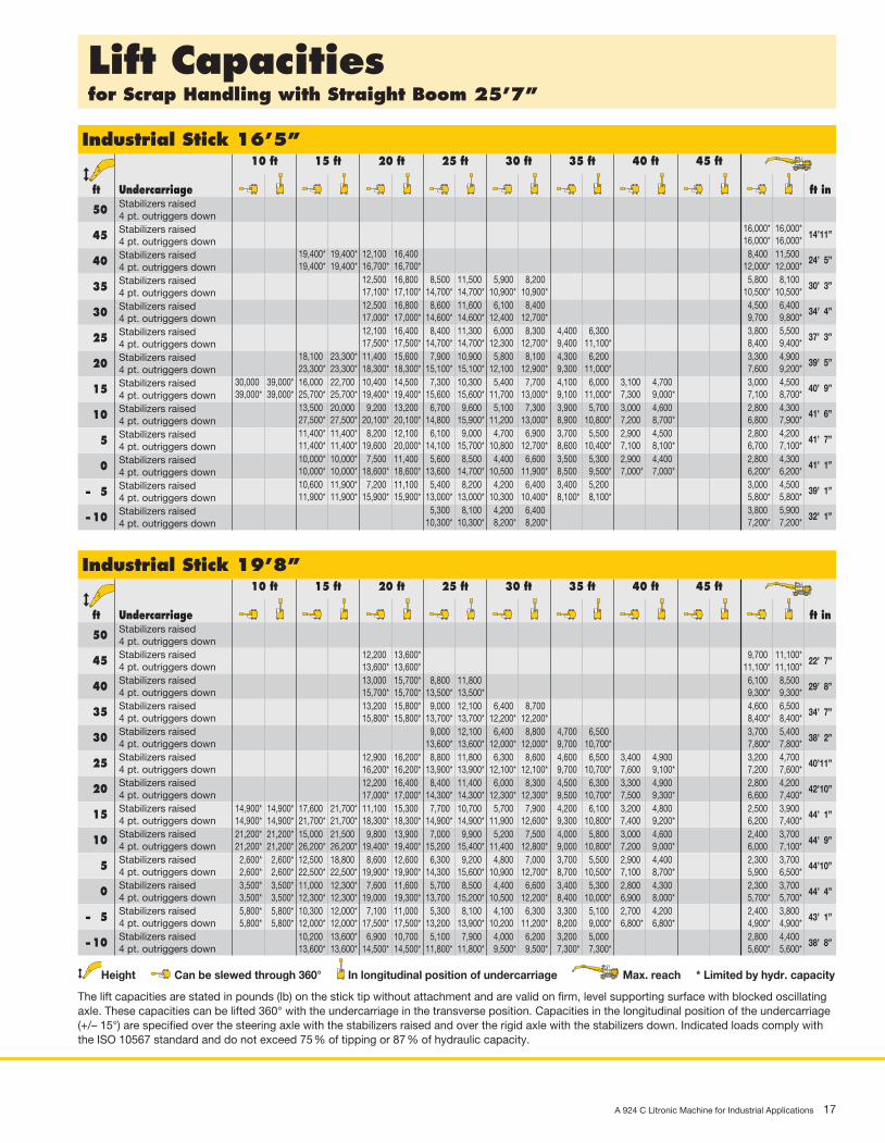
Lift Capacitiesfor Scrap Handling with Straight Boom 25’7”
Industrial Stick 16’5” 10 ft 15 ft 20 ft 25 ft 30 ft 35 ft 40 ft 45 ft
ft Undercarriage ft in Stabilizers raised 50 4 pt. outriggers down Stabilizers raised 45 4 pt. outriggers down Stabilizers raised 40 4 pt. outriggers down Stabilizers raised 35 4 pt. outriggers down Stabilizers raised 30 4 pt. outriggers down Stabilizers raised 25 4 pt. outriggers down Stabilizers raised 20 4 pt. outriggers down Stabilizers raised 15 4 pt. outriggers down Stabilizers raised 10 4 pt. outriggers down Stabilizers raised 5 4 pt. outriggers down Stabilizers raised 0 4 pt. outriggers down Stabilizers raised – 5 4 pt. outriggers down Stabilizers raised – 10 4 pt. outriggers down
16,000* 16,000* 16,000* 16,000*
14’11”
19,400* 19,400* 12,100 16,400 8,400 11,500 19,400* 19,400* 16,700* 16,700* 12,000* 12,000*
24’ 5”
12,500 16,800 8,500 11,500 5,900 8,200 5,800 8,100 17,100* 17,100* 14,700* 14,700* 10,900* 10,900* 10,500* 10,500*
30’ 3”
12,500 16,800 8,600 11,600 6,100 8,400 4,500 6,400 17,000* 17,000* 14,600* 14,600* 12,400 12,700* 9,700 9,800*
34’ 4”
12,100 16,400 8,400 11,300 6,000 8,300 4,400 6,300 3,800 5,500 17,500* 17,500* 14,700* 14,700* 12,300 12,700* 9,400 11,100* 8,400 9,400*
37’ 3”
18,100 23,300* 11,400 15,600 7,900 10,900 5,800 8,100 4,300 6,200 3,300 4,900 23,300* 23,300* 18,300* 18,300* 15,100* 15,100* 12,100 12,900* 9,300 11,000* 7,600 9,200*
39’ 5”
30,000 39,000* 16,000 22,700 10,400 14,500 7,300 10,300 5,400 7,700 4,100 6,000 3,100 4,700 3,000 4,500 39,000* 39,000* 25,700* 25,700* 19,400* 19,400* 15,600 15,600* 11,700 13,000* 9,100 11,000* 7,300 9,000* 7,100 8,700*
40’ 9”
13,500 20,000 9,200 13,200 6,700 9,600 5,100 7,300 3,900 5,700 3,000 4,600 2,800 4,300 27,500* 27,500* 20,100* 20,100* 14,800 15,900* 11,200 13,000* 8,900 10,800* 7,200 8,700* 6,800 7,900*
41’ 6”
11,400* 11,400* 8,200 12,100 6,100 9,000 4,700 6,900 3,700 5,500 2,900 4,500 2,800 4,200 11,400* 11,400* 19,600 20,000* 14,100 15,700* 10,800 12,700* 8,600 10,400* 7,100 8,100* 6,700 7,100*
41’ 7”
10,000* 10,000* 7,500 11,400 5,600 8,500 4,400 6,600 3,500 5,300 2,900 4,400 2,800 4,300 10,000* 10,000* 18,600* 18,600* 13,600 14,700* 10,500 11,900* 8,500 9,500* 7,000* 7,000* 6,200* 6,200*
41’ 1”
10,600 11,900* 7,200 11,100 5,400 8,200 4,200 6,400 3,400 5,200 3,000 4,500 11,900* 11,900* 15,900* 15,900* 13,000* 13,000* 10,300 10,400* 8,100* 8,100* 5,800* 5,800*
39’ 1”
5,300 8,100 4,200 6,400 3,800 5,900 10,300* 10,300* 8,200* 8,200* 7,200* 7,200*
32’ 1”
Industrial Stick 19’8” 10 ft 15 ft 20 ft 25 ft 30 ft 35 ft 40 ft 45 ft
ft Undercarriage ft in Stabilizers raised 50 4 pt. outriggers down Stabilizers raised 45 4 pt. outriggers down Stabilizers raised 40 4 pt. outriggers down Stabilizers raised 35 4 pt. outriggers down Stabilizers raised 30 4 pt. outriggers down Stabilizers raised 25 4 pt. outriggers down Stabilizers raised 20 4 pt. outriggers down Stabilizers raised 15 4 pt. outriggers down Stabilizers raised 10 4 pt. outriggers down Stabilizers raised 5 4 pt. outriggers down Stabilizers raised 0 4 pt. outriggers down Stabilizers raised – 5 4 pt. outriggers down Stabilizers raised – 10 4 pt. outriggers down
12,200 13,600* 9,700 11,100* 13,600* 13,600* 11,100* 11,100*
22’ 7”
13,000 15,700* 8,800 11,800 6,100 8,500 15,700* 15,700* 13,500* 13,500* 9,300* 9,300*
29’ 8”
13,200 15,800* 9,000 12,100 6,400 8,700 4,600 6,500 15,800* 15,800* 13,700* 13,700* 12,200* 12,200* 8,400* 8,400*
34’ 7”
9,000 12,100 6,400 8,800 4,700 6,500 3,700 5,400 13,600* 13,600* 12,000* 12,000* 9,700 10,700* 7,800* 7,800*
38’ 2”
12,900 16,200* 8,800 11,800 6,300 8,600 4,600 6,500 3,400 4,900 3,200 4,700 16,200* 16,200* 13,900* 13,900* 12,100* 12,100* 9,700 10,700* 7,600 9,100* 7,200 7,600*
40’11”
12,200 16,400 8,400 11,400 6,000 8,300 4,500 6,300 3,300 4,900 2,800 4,200 17,000* 17,000* 14,300* 14,300* 12,300* 12,300* 9,500 10,700* 7,500 9,300* 6,600 7,400*
42’10”
14,900* 14,900* 17,600 21,700* 11,100 15,300 7,700 10,700 5,700 7,900 4,200 6,100 3,200 4,800 2,500 3,900 14,900* 14,900* 21,700* 21,700* 18,300* 18,300* 14,900* 14,900* 11,900 12,600* 9,300 10,800* 7,400 9,200* 6,200 7,400*
44’ 1”
21,200* 21,200* 15,000 21,500 9,800 13,900 7,000 9,900 5,200 7,500 4,000 5,800 3,000 4,600 2,400 3,700 21,200* 21,200* 26,200* 26,200* 19,400* 19,400* 15,200 15,400* 11,400 12,800* 9,000 10,800* 7,200 9,000* 6,000 7,100*
44’ 9”
2,600* 2,600* 12,500 18,800 8,600 12,600 6,300 9,200 4,800 7,000 3,700 5,500 2,900 4,400 2,300 3,700 2,600* 2,600* 22,500* 22,500* 19,900* 19,900* 14,300 15,600* 10,900 12,700* 8,700 10,500* 7,100 8,700* 5,900 6,500*
44’10”
3,500* 3,500* 11,000 12,300* 7,600 11,600 5,700 8,500 4,400 6,600 3,400 5,300 2,800 4,300 2,300 3,700 3,500* 3,500* 12,300* 12,300* 19,000 19,300* 13,700 15,200* 10,500 12,200* 8,400 10,000* 6,900 8,000* 5,700* 5,700*
44’ 4”
5,800* 5,800* 10,300 12,000* 7,100 11,000 5,300 8,100 4,100 6,300 3,300 5,100 2,700 4,200 2,400 3,800 5,800* 5,800* 12,000* 12,000* 17,500* 17,500* 13,200 13,900* 10,200 11,200* 8,200 9,000* 6,800* 6,800* 4,900* 4,900*
43’ 1”
10,200 13,600* 6,900 10,700 5,100 7,900 4,000 6,200 3,200 5,000 2,800 4,400 13,600* 13,600* 14,500* 14,500* 11,800* 11,800* 9,500* 9,500* 7,300* 7,300* 5,600* 5,600*
38’ 8”
Height Can be slewed through 360° In longitudinal position of undercarriage Max. reach * Limited by hydr. capacity
The lift capacities are stated in pounds (lb) on the stick tip without attachment and are valid on firm, level supporting surface with blocked oscillating axle. These capacities can be lifted 360° with the undercarriage in the transverse position. Capacities in the longitudinal position of the undercarriage (+/– 15°) are specified over the steering axle with the stabilizers raised and over the rigid axle with the stabilizers down. Indicated loads comply with the ISO 10567 standard and do not exceed 75 % of tipping or 87 % of hydraulic capacity.

18 A 924 C Litronic Machine for Industrial Applications
Industrial Attachmentfor Loose Material with Gooseneck Boom 21’4”
Attachment EnvelopeIndustrial-type gooseneck boom pinned in rear bearing of boom foot bracket
1 with industrial stick 13’1”2 with industrial stick 16’5”3 with industrial stick 13’1” and clamshell model 10 B4 with industrial stick 16’5” and clamshell model 10 B
Operating WeightOperating weight includes basic machine A 924 C litronic̀ with 4 pt. outriggers, hydr. cab elevation, 8 tires plus spacer rings and industrial attachment with industrial-type gooseneck boom 21’4”.
with clamshell model 10 B/1.31 yd3 shells for loose material Weightand industrial stick 13’1” 59,850 lband industrial stick 16’5” 60,100 lb
0m
0 ft
123456789
51015202530
10
00
-1
-2
-3
-4
-5
-5
-10
-15
1
2
3
4
5
6
5
10
15
20
7
8
9
25
30
10
11
mft
35
12
13
40
1112
3540
-6
-7
-20
13
1
2
3
4
A 924 C Litronic Machine for Industrial Applications 19
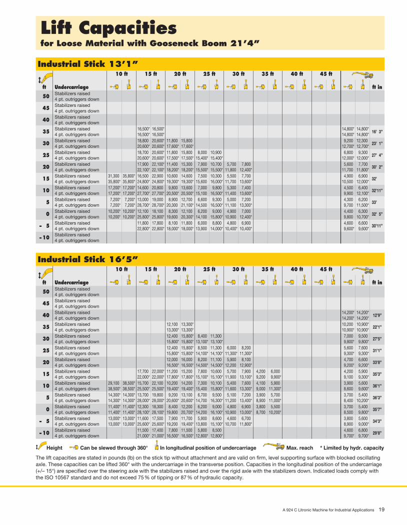
Lift Capacitiesfor Loose Material with Gooseneck Boom 21’4”
Industrial Stick 13’1” 10 ft 15 ft 20 ft 25 ft 30 ft 35 ft 40 ft 45 ft
ft Undercarriage ft in Stabilizers raised 50 4 pt. outriggers down Stabilizers raised 45 4 pt. outriggers down Stabilizers raised 40 4 pt. outriggers down Stabilizers raised 35 4 pt. outriggers down Stabilizers raised 30 4 pt. outriggers down Stabilizers raised 25 4 pt. outriggers down Stabilizers raised 20 4 pt. outriggers down Stabilizers raised 15 4 pt. outriggers down Stabilizers raised 10 4 pt. outriggers down Stabilizers raised 5 4 pt. outriggers down Stabilizers raised 0 4 pt. outriggers down Stabilizers raised – 5 4 pt. outriggers down Stabilizers raised – 10 4 pt. outriggers down
16,500* 16,500* 14,800* 14,800* 16,500* 16,500* 14,800* 14,800*
16’ 3”
18,800 20,600* 11,800 15,800 9,200 12,300 20,600* 20,600* 17,600* 17,600* 12,700* 12,700*
23’ 1”
18,700 20,600* 11,800 15,800 8,000 10,900 6,800 9,300 20,600* 20,600* 17,500* 17,500* 15,400* 15,400* 12,000* 12,000*
27’ 4”
17,900 22,100* 11,400 15,300 7,900 10,700 5,700 7,800 5,600 7,700 22,100* 22,100* 18,200* 18,200* 15,500* 15,500* 11,800 12,400* 11,700 11,800*
30’ 2”
31,300 35,800* 16,500 22,900 10,600 14,600 7,500 10,300 5,500 7,700 4,900 6,900 35,800* 35,800* 24,800* 24,800* 19,300* 19,300* 15,600 16,000* 11,700 13,600* 10,500 12,000*
32’
17,200* 17,200* 14,600 20,800 9,800 13,600 7,000 9,800 5,300 7,400 4,500 6,400 17,200* 17,200* 27,700* 27,700* 20,500* 20,500* 15,100 16,500* 11,400 13,600* 9,900 12,100*
32’11”
7,200* 7,200* 13,000 19,000 8,900 12,700 6,600 9,300 5,000 7,200 4,300 6,200 7,200* 7,200* 28,700* 28,700* 20,300 21,100* 14,500 16,500* 11,100 13,300* 9,700 11,500*
33’
10,200* 10,200* 12,100 18,100 8,300 12,100 6,200 9,000 4,900 7,000 4,400 6,300 10,200* 10,200* 25,800* 25,800* 19,600 20,300* 14,100 15,800* 10,900 12,400* 9,800 10,700*
32’ 5”
11,800 17,800 8,100 11,800 6,000 8,800 4,800 6,900 4,600 6,600 22,800* 22,800* 18,000* 18,000* 13,900 14,000* 10,400* 10,400* 9,600* 9,600*
30’11”
Industrial Stick 16’5” 10 ft 15 ft 20 ft 25 ft 30 ft 35 ft 40 ft 45 ft
ft Undercarriage ft in Stabilizers raised 50 4 pt. outriggers down Stabilizers raised 45 4 pt. outriggers down Stabilizers raised 40 4 pt. outriggers down Stabilizers raised 35 4 pt. outriggers down Stabilizers raised 30 4 pt. outriggers down Stabilizers raised 25 4 pt. outriggers down Stabilizers raised 20 4 pt. outriggers down Stabilizers raised 15 4 pt. outriggers down Stabilizers raised 10 4 pt. outriggers down Stabilizers raised 5 4 pt. outriggers down Stabilizers raised 0 4 pt. outriggers down Stabilizers raised – 5 4 pt. outriggers down Stabilizers raised – 10 4 pt. outriggers down
14,200* 14,200* 14,200* 14,200*
12’9”
12,100 13,300* 10,200 10,900* 13,300* 13,300* 10,900* 10,900*
22’1”
12,400 15,800* 8,400 11,300 7,000 9,500 15,800* 15,800* 13,100* 13,100* 9,800* 9,800*
27’5”
12,400 15,800* 8,500 11,300 6,000 8,200 5,600 7,600 15,800* 15,800* 14,100* 14,100* 11,300* 11,300* 9,300* 9,300*
31’1”
12,000 16,000 8,200 11,100 5,900 8,100 4,700 6,600 16,500* 16,500* 14,500* 14,500* 12,200 12,900* 9,200* 9,200*
33’8”
17,700 22,000* 11,200 15,200 7,800 10,600 5,700 7,900 4,200 6,000 4,200 5,900 22,000* 22,000* 17,800* 17,800* 15,100* 15,100* 11,900 13,100* 9,200 9,900* 9,100 9,300*
35’3”
29,100 38,500* 15,700 22,100 10,200 14,200 7,300 10,100 5,400 7,600 4,100 5,900 3,900 5,600 38,500* 38,500* 25,500* 25,500* 19,400* 19,400* 15,400 15,800* 11,600 13,300* 9,000 11,300* 8,600 9,600*
36’1”
14,300* 14,300* 13,700 19,800 9,200 13,100 6,700 9,500 5,100 7,200 3,900 5,700 3,700 5,400 14,300* 14,300* 28,000* 28,000* 20,600* 20,600* 14,700 16,300* 11,200 13,400* 8,900 11,000* 8,400 10,200*
36’3”
11,400* 11,400* 12,300 18,300 8,400 12,200 6,200 9,000 4,800 6,900 3,800 5,500 3,700 5,400 11,400* 11,400* 28,100* 28,100* 19,800 20,700* 14,200 16,100* 10,900 13,000* 8,700 10,200* 8,500 9,800*
35’7”
13,000* 13,000* 11,600 17,500 7,900 11,700 5,900 8,600 4,600 6,700 3,800 5,600 13,000* 13,000* 25,600* 25,600* 19,200 19,400* 13,800 15,100* 10,700 11,800* 8,900 9,000*
34’3”
11,500 17,400 7,800 11,500 5,800 8,500 4,600 6,800 21,000* 21,000* 16,500* 16,500* 12,800* 12,800* 9,700* 9,700*
29’8”
Height Can be slewed through 360° In longitudinal position of undercarriage Max. reach * Limited by hydr. capacity
The lift capacities are stated in pounds (lb) on the stick tip without attachment and are valid on firm, level supporting surface with blocked oscillating axle. These capacities can be lifted 360° with the undercarriage in the transverse position. Capacities in the longitudinal position of the undercarriage (+/– 15°) are specified over the steering axle with the stabilizers raised and over the rigid axle with the stabilizers down. Indicated loads comply with the ISO 10567 standard and do not exceed 75 % of tipping or 87 % of hydraulic capacity.

20 A 924 C Litronic Machine for Industrial Applications
Industrial Attachmentfor Recycling with Straight Boom 22’4”
Attachment EnvelopeIndustrial-type straight boom pinned in rear bearing of boom foot bracket
with industrial stick 16’5” and Liebherr sorting grapple
Operating WeightOperating weight includes basic machine A 924 C litronic̀ with 4 pt. outriggers, hydr. cab elevation, 8 solid tires plus spacer rings and industrial attachment with industrial-type straight boom 22’4”.
with Liebherr sorting grapple SG 30/1.05 yd3 tines Weightand industrial stick with tipping kinematics 16’5” 63,600 lb
Industrial Stick 16’5” 10 ft 15 ft 20 ft 25 ft 30 ft 35 ft 40 ft 45 ft
ft Undercarriage ft in Stabilizers raised 40 4 pt. outriggers down Stabilizers raised 35 4 pt. outriggers down Stabilizers raised 30 4 pt. outriggers down Stabilizers raised 25 4 pt. outriggers down Stabilizers raised 20 4 pt. outriggers down Stabilizers raised 15 4 pt. outriggers down Stabilizers raised 10 4 pt. outriggers down Stabilizers raised 5 4 pt. outriggers down Stabilizers raised 0 4 pt. outriggers down Stabilizers raised – 5 4 pt. outriggers down Stabilizers raised – 10 4 pt. outriggers down
17,900 19,100* 11,500 14,000* 19,100* 19,100* 14,000* 14,000*
19’ 3”
11,600 15,800 7,600 10,500 6,800 9,500 17,200* 17,200* 13,500* 13,500* 11,000* 11,000*
26’ 3”
11,900 16,000 7,900 10,800 5,400 7,600 5,000 7,100 16,700* 16,700* 14,500* 14,500* 11,700 11,900* 9,800* 9,800*
30’11”
11,700 15,900 7,900 10,800 5,500 7,700 4,000 5,900 16,800* 16,800* 14,500* 14,500* 11,900 12,600* 9,100* 9,100*
34’ 2”
18,300 19,700* 11,300 15,400 7,600 10,500 5,400 7,600 3,800 5,600 3,400 5,100 19,700* 19,700* 17,500* 17,500* 14,800* 14,800* 11,700 12,700* 8,900 10,700* 8,200 8,700*
36’ 5”
15,800* 15,800* 16,700 23,400 10,500 14,500 7,200 10,100 5,100 7,300 3,700 5,500 3,100 4,700 15,800* 15,800* 24,000* 24,000* 18,700* 18,700* 15,300* 15,300* 11,500 12,800* 8,800 10,700* 7,600 8,600*
37’11”
27,100 29,900* 14,700 21,100 9,500 13,500 6,600 9,500 4,800 7,000 3,600 5,400 2,900 4,400 29,900* 29,900* 26,700* 26,700* 19,800* 19,800* 14,900 15,700* 11,100 12,800* 8,600 10,400* 7,300 8,200*
38’ 9”
2,100* 2,100* 12,700 18,900 8,500 12,400 6,100 8,900 4,500 6,700 3,400 5,200 2,800 4,400 2,100* 2,100* 27,900* 27,900* 20,200 20,200* 14,300 15,700* 10,800 12,500* 8,500 9,900* 7,200 7,300*
38’10”
3,800* 3,800* 11,500 17,600 7,800 11,600 5,600 8,400 4,200 6,400 3,300 5,100 2,800 4,400 3,800* 3,800* 17,600* 17,600* 19,300 19,400* 13,700 15,000* 10,500 11,700* 8,300 8,800* 6,100* 6,100*
38’ 3”
11,000 17,100 7,400 11,200 5,400 8,100 4,100 6,300 3,200 5,000 3,200 4,900 17,400* 17,400* 17,000* 17,000* 13,200* 13,200* 10,100* 10,100* 6,800* 6,800* 6,300* 6,300*
35’ 8”
7,300 11,100 5,300 8,100 4,400 6,800 13,100* 13,100* 10,200* 10,200* 8,300* 8,300*
28’ 4”
0m
0ft
123456789
51015202530
10
00
-1
-2
-3
-4
-5
-5
-10
-15
1
2
3
4
5
6
5
10
15
20
7
8
9
25
30
10
11
mft
35
12
13
40
1112
3540
-6-20
14
15
45
50
1314
45
16
Height Can be slewed through 360° In longitudinal position of undercarriage Max. reach * Limited by hydr. capacity
The lift capacities are stated in pounds (lb) on the stick tip without attachment and are valid on firm, level supporting surface with blocked oscillating axle. These capacities can be lifted 360° with the undercarriage in the transverse position. Capacities in the longitudinal position of the undercarriage (+/– 15°) are specified over the steering axle with the stabilizers raised and over the rigid axle with the stabilizers down. Indicated loads comply with the ISO 10567 standard and do not exceed 75 % of tipping or 87 % of hydraulic capacity.

A 924 C Litronic Machine for Industrial Applications 21
Choice of Cab Elevations and Cab Protections
Rigid Cab ElevationHeight 2’ 7” 3’11” 4’11”
A 10’ 7” 11’11” 12’11”B 11’ 9” 13’ ” 14’ ”C 13’ 4” 14’ 8” 15’ 8”D 2’10” 2’10” 2’10”
A rigid cab elevation has a fixed eye level height. For a lower trans-port height the shell of the cab can be removed. The overall height is then dimension A.
Hydraulic Cab Elevation (Parallelogram)B1 9’ 1”B2 17’ 4”C1 10’ 9”C2 18’11”D1 4’ 9”D2 5’ 7”E 10’ 6”
The parallelogram cab riser allows the operator to choose his field of view between dimensions B1 and B2. For a transport height lower than C1 the shell of the cab can be removed. The overall height is then E.
D
BC
A
D1
C1
B2
B1
D2
C2
E
FOPS Guard Front Guard

Shells for Loose Material Clamshell Model 10 B
22 A 924 C Litronic Machine for Industrial Applications
Variety of Tools
Shells for loose material with cutting edge (without teeth)Cutting width of shells ft in 3’3” 4’11” 5’11”Capacity yd3 1.31 1.96 2.35For loose material, specific weight up to lb/yd3 2,528 2,528 2,528Weight lb 2,293 2,601 3,142
Multiple Tine Grapples open tines semi-closed tines closed tines
Grapple Model 64 Capacity yd3 0.52 0.78 0.52 0.78 0.52 0.78(4 tines) Weight lb 1,863 2,491 2,326 2,932 2,337 3,351Grapple Model 65 Capacity yd3 0.52 0.78 0.52 0.78 0.52 0.78(5 tines) Weight lb 2,535 2,712 2,833 3,120 2,921 3,351
Crane Hook with SuspensionMax. load lb 27,558Height with suspension ft in 3’1”Weight lb 212
Magnet Devices/Lifting MagnetsGenerator kW 13 13Electromagnets with SuspensionPower kW 4.5 6Diameter of magnet ft in 3’5” 3’11”Height with suspension ft in 3’7” 3’ 7”Weight lb 1,653 2,624
Wood GrapplesSize in2 2,015 2,635 3,255Width ft in 2’8” 2’ 8” 2’ 8”Opening width inside ft in 8’8” 9’ 4” 10’ 9”Opening width outside ft in 9’8” 10’ 5” 11’10”Overall height open ft in 7’8” 7’10” 8’ 3”Overall height closed ft in 9’8” 10’ 10’10”Weight complete lb 3,693 3,913 4,299

A 924 C Litronic Machine for Industrial Applications 23
Equipment
• = Standard, + = Option
Options and/or special attachments, supplied by vendors other than Liebherr, are only to be installed with the knowledge and approval of Liebherr to retain warranty.
UndercarriageTwo circuit travel brake with accumulator •Travel motor protection +Outrigger cylinder rod guards +Travel speed switch •New tires •Service free parking brake •Independent outrigger control +Choice of tires +Auto check valve on each stabilizer cylinder •Proportional power steering •Customized colors +Two lockable storage boxes •Two-speed power shift transmission •
Operator’s CabStorage tray •Displays for engine operating condition •Mechanical hour meters, reader outside cab •Roof hatch •6-way adjustable seat •Air suspension seat with heating and head-rest +Seat and consoles independently adjustable •Extinguisher +Removable customized foot mat •Dome light •Hydraulic cab +Rigid cab +Cab heater with defroster •Coat hook •Air conditioning •Electric cooler +Adjustable steering wheel •Bullet proof window (fixed installation – can not be opened) +Radio stereo +Radio installation +Rain visor over front window opening •Beacon +Tinted windows •Door with sliding window •Optical warning if outriggers are not fully retracted +Auxiliary heating +Sun shade +Sun blinds •Electronic theft protection +Wiper blades •Cigarette lighter and ashtray •Additional flood lights +
UppercarriageElectric fuel tank filler pump +Maintenance-free swing brake lock •Handrails, Non slip surfaces •Main switch for electric circuit •Engine hood with lift assistance •Pedal controlled positioning swing brake +Reverse travel warning system +Sound insulation •Customized colors +Pin lock upper/lower +Maintenance-free HD-batteries •Extended tool kit +Lockable tool box •Tool kit •
HydraulicsHydraulic tank shut-off valve •Extra hydr. control for hydr. swivel •Pressure compensation •Hook up for pressure checks •Pressure storage for controlled lowering of attachments with engine turned off •Filter with partial micro filtration (5 µm) •Electronic pump regulation •Stepless mode system (ECO) •Flow compensation •Four mixed modes, can also be adjusted •Full flow micro filtration +Bio degradable hydraulic oil +Tool Control +Additional hydraulic circuits +
AttachmentFlood lights •Hydr. lines for clam operation in sticks •Industrial-type gooseneck sticks with remote hydraulic pin puller +Sealed pivots •Safety lift hook +Liebherr line of clams +Liebherr semi-automatic central lubrication system •Liebherr fully-automatic central lubrication system +LIKUFIX +Safety check valves on hoist cylinder •Safety check valves on stick cylinder •Hose quick connection •Hydraulic or manual quick change tool adapter +Customized colors +Special buckets and tools +Overload warning device +Two way valves for bucket/clam use +Locking of connections for clam operation +Cylinders with shock absorber •
EngineTurbo charger •After-cooled •Sensor controlled engine idling •Liebherr particle filter +Unit pump system •Air filter with pre-cleaner main- and safety element •
All illustrations and data may differ from standard equipment. Subject to change without notice.

NTB_RS_US_D_5.indd 1 02.12.10 15:15
Liebherr Construction Equipment Co.4100 Chestnut Avenue, Newport News, VA 23607, USA +1 (757) 245 5251, Fax +1 (757) 928 8701www.liebherr.us, E-Mail: [email protected]
Printed in Germany by Eberl RG-BK-RP LHB/VF 10424669-2.5-02.11_enUS
The Liebherr Group of Companies
Wide Product RangeThe Liebherr Group is one of the largest construction equipment manufacturers in the world. Liebherr’s high-value products and services enjoy a high reputation in many other fields, too. The wide range includes domes-tic appliances, aerospace and transportation systems, machine tools and maritime cranes.
Exceptional Customer BenefitEvery product line provides a complete range of models in many different versions. With both their technical excel-lence and acknowledged quality, Liebherr products offer a maximum of customer benefits in practical application.
State-of-the-art TechnologyTo provide consistent, top quality products, Liebherr attaches great importance to each product area, its components and core technologies. Important modules and components are developed and manufactured in-house, for instance the entire drive and control techno-logy for construction equipment and mining trucks.
Worldwide and IndependentHans Liebherr founded the Liebherr family company in 1949. Since that time, the enterprise has steadily grown to a group of more than 100 companies with over 32,000 employees located on all continents. The corporate headquarters of the Group is Liebherr-International AG in Bulle, Switzerland. The Liebherr family is the sole owner of the company.
www.liebherr.us

Prinect PDF Report 3.0.72 - 1 - 03.02.2011 16:31:01
Dokument ÜbersichtDateiname: A924C_U_BT_enUS_02_2011.pdfTitel: -Erstellt mit: Adobe InDesign CS5 (7.0.1)Anwendung: Adobe PDF Library 9.9Verfasser: -Erstellt am: 03.02.2011 16:29:41Geändert am: 03.02.2011 16:30:56Dateigröße: 65.8 MByte / 67400.4 KByteTrapped: NeinOutput Intent: -PDF/X Version: -PDF-Version: 1.4Anzahl Seiten: 11Medien-Rahmen: 671.01 x 851.01 ptEndformat-Rahmen: 612.00 x 792.00 pt
Zusammenfassung Fehler Warnung Repariert InfoDokument - - - -PDF/X - - - -Seiten - - - -Farben - - - -Schriften - - - -Bilder - - - 22Inhalt - - - -
BilderAuflösung von Farbbildern 226 dpi ist unter 800 dpi (4-5)Auflösung von Farbbildern 263 dpi ist unter 800 dpi (6)Auflösung von Farbbildern 287 dpi ist unter 800 dpi (8-9)Auflösung von Farbbildern 290 dpi ist unter 800 dpi (2-3)Auflösung von Farbbildern 300 dpi ist unter 800 dpi (1,4-5,7,10-11)Auflösung von Farbbildern 355 dpi ist unter 800 dpi (6)Auflösung von Farbbildern 361 dpi ist unter 800 dpi (10-11)Auflösung von Farbbildern 370 dpi ist unter 800 dpi (10)Auflösung von Farbbildern 380 dpi ist unter 800 dpi (9)Auflösung von Farbbildern 382 dpi ist unter 800 dpi (8)Auflösung von Farbbildern 399 dpi ist unter 800 dpi (6-7)Auflösung von Farbbildern 448 dpi ist unter 800 dpi (8)
Sonstige InformationenFarbseparationen: 5 1 Problem(e) mit Farbnamen
CMYKHKS 04 -> HKS 4 K

Prinect PDF Report 3.0.72 - 2 - 03.02.2011 16:31:01
FarbräumeDeviceCMYK / Separation
Schriften: 5FuturaLT-ExtraBold Type1 / WinAnsi / eingebettete UntergruppeHelvetica TrueType / WinAnsi / eingebettete UntergruppeHelveticaNeueLT-Bold Type1 / WinAnsi / eingebettete UntergruppeHelveticaNeueLT-Roman Type1 (CID) / Identity-H / eingebettete UntergruppeHelveticaNeueLT-Roman Type1 / Custom / eingebettete Untergruppe