Machine Controller MP2200 USER'S MANUAL · User's Manual Motion Programming SIEZ-C887-1.3 Describes...
300
YASKAWA YASKAWA MANUAL NO. SIEP C880700 14A Machine Controller MP2200 USER'S MANUAL
Transcript of Machine Controller MP2200 USER'S MANUAL · User's Manual Motion Programming SIEZ-C887-1.3 Describes...
YASKAWA
YASKAWA MANUAL NO. SIEP C880700 14A
Machine Controller MP2200USER'S MANUAL

Copyright © 2004 YASKAWA ELECTRIC CORPORATION
All rights reserved. No part of this publication may be reproduced, stored in a retrieval system, or transmitted, in any form, or by any means, mechanical, electronic, photocopying, recording, or otherwise, without the prior written permission of Yaskawa. No patent liability is assumed with respect to the use of the information contained herein. Moreover, because Yaskawa is con-stantly striving to improve its high-quality products, the information contained in this manual is subject to change without notice. Every precaution has been taken in the preparation of this manual. Nevertheless, Yaskawa assumes no responsibility for errors or omissions. Neither is any liability assumed for damages resulting from the use of the information contained in this publication.
iii
Using this Manual
Please read this manual to ensure correct usage of the MP2200 system. Keep this manual in a safe place for future reference.
Basic Terms
Unless otherwise specified, the following definitions are used:
Manual Configuration
Read the chapters of this manual as required by the purpose.
• MP2200: Machine Controller MP2200
• MPE720: The Programming Device Software or a Programming Device (i.e., a personal computer) running the Pro-gramming Device Software
• PC: Programmable Logic Controller
Chapter
Selecting Models and Peripheral Devices
Studying Specifications and Ratings
Designing the System
Installation and Wiring
Trial Operation
Maintenance and
Inspection
Chapter 1 Overview of the MP2200
Applicable − − − − −
Chapter 2System Configuration
Applicable − − − − −
Chapter 3System Startup
− − − − Applicable −
Chapter 4Module Specifications
Applicable Applicable Applicable Applicable − −
Chapter 5Mounting and Wiring
− Applicable Applicable Applicable − −
Chapter 6Basic System Operation
− − Applicable − Applicable −
Chapter 7Maintenance and Inspection
− − − − − Applicable
Chapter 8Troubleshooting
− − − − Applicable Applicable

iv
Visual Aids
The following aids are used to indicate certain types of information for easier reference.
Indicates important information that should be memorized.
Indicates supplemental information.
Indicates application examples.
Describes technical terms that are difficult to understand, or appear in the text without an explana-tion being given.
Indication of Reverse Signals
In this manual, the names of reverse signals (ones that are valid when low) are written with a forward slash (/) before the signal name, as shown in the following example:
Copyrights
• S-ON = /S-ON
• P-CON = /P-CON
• DeviceNet is a registered trademark of the ODVA (Open DeviceNet Venders Association).• PROFIBUS is a trademark of the PROFIBUS User Organization.• Ethernet is a registered trademark of the Xerox Corporation.• Microsoft, Windows, Windows NT, and Internet Explorer are registered trademarks of the Microsoft Corporation.• Pentium is a registered trademark of the Intel Corporation.• Other product names and company names are the trademarks or registered trademarks of the respective company. “TM”
and the mark do not appear with product or company names in this manual.
IMPORTANT
INFO
EXAMPLE
TERMS
v
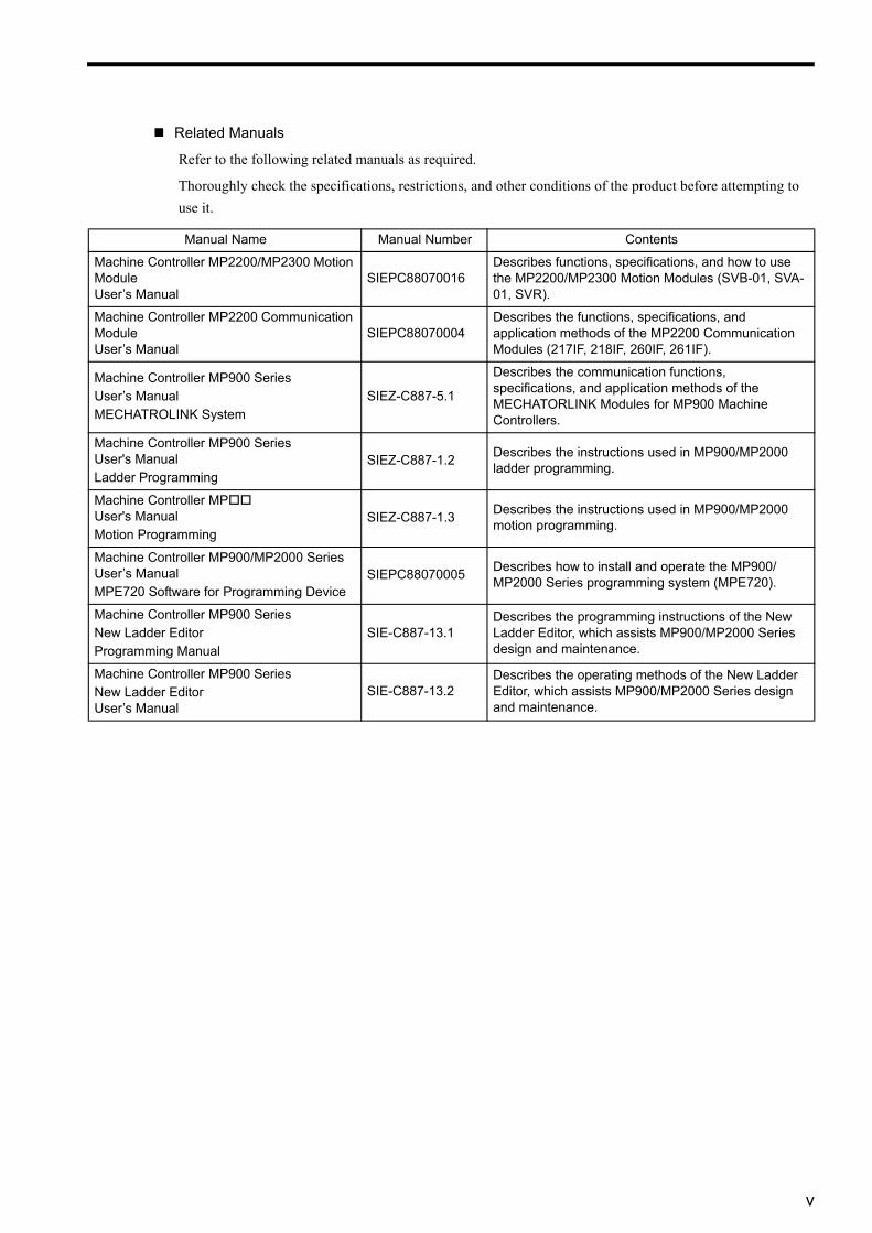
Related Manuals
Refer to the following related manuals as required.
Thoroughly check the specifications, restrictions, and other conditions of the product before attempting to use it.
Manual Name Manual Number Contents
Machine Controller MP2200/MP2300 Motion Module User’s Manual
SIEPC88070016Describes functions, specifications, and how to use the MP2200/MP2300 Motion Modules (SVB-01, SVA-01, SVR).
Machine Controller MP2200 Communication ModuleUser’s Manual
SIEPC88070004Describes the functions, specifications, and application methods of the MP2200 Communication Modules (217IF, 218IF, 260IF, 261IF).
Machine Controller MP900 Series User’s ManualMECHATROLINK System
SIEZ-C887-5.1
Describes the communication functions, specifications, and application methods of the MECHATORLINK Modules for MP900 Machine Controllers.
Machine Controller MP900 SeriesUser's Manual Ladder Programming
SIEZ-C887-1.2 Describes the instructions used in MP900/MP2000 ladder programming.
Machine Controller MPUser's ManualMotion Programming
SIEZ-C887-1.3 Describes the instructions used in MP900/MP2000 motion programming.
Machine Controller MP900/MP2000 Series User’s Manual MPE720 Software for Programming Device
SIEPC88070005 Describes how to install and operate the MP900/MP2000 Series programming system (MPE720).
Machine Controller MP900 Series New Ladder EditorProgramming Manual
SIE-C887-13.1Describes the programming instructions of the New Ladder Editor, which assists MP900/MP2000 Series design and maintenance.
Machine Controller MP900 Series New Ladder Editor User’s Manual
SIE-C887-13.2Describes the operating methods of the New Ladder Editor, which assists MP900/MP2000 Series design and maintenance.

vi
Safety Information
The following conventions are used to indicate precautions in this manual. Failure to heed precautions pro-vided in this manual can result in serious or possibly even fatal injury or damage to the products or to related equipment and systems.
Indicates precautions that, if not heeded, could possibly result in loss of life or serious injury.
Indicates precautions that, if not heeded, could result in relatively serious or minor injury, damage to the product, or faulty operation.
In some situations, the precautions indicated could have serious consequences if not heeded.
Indicates prohibited actions that must not be performed. For example, this symbol
would be used as follows to indicate that fire is prohibited: .
Indicates compulsory actions that must be performed. For example, this symbol would
be used as follows to indicate that grounding is compulsory: .
WARNING
CAUTION
PROHIBITED
MANDATORY
vii
Safety Precautions
The following precautions are for checking products on delivery, storage, transportation, installation, wiring,
operation, maintenance, inspection, and disposal. These precautions are important and must be observed.
• Before starting operation in combination with the machine, ensure that an emergency stop procedure has been provided and is working correctly.
There is a risk of injury.
• Do not touch anything inside the MP2200.
There is a risk of electrical shock.
• Always keep the front cover attached when power is being supplied.
There is a risk of electrical shock.
• Observe all procedures and precautions given in this manual for trial operation.
Operating mistakes while the servomotor and machine are connected can cause damage to the machine or even accidents resulting in injury or death.
• Do not remove the front cover, cables, connector, or options while power is being supplied.
There is a risk of electrical shock.
• Do not allow installation, disassembly, or repairs to be performed by anyone other than specified per-sonnel.
There is a risk of electrical shock or injury.
• Do not damage, pull on, apply excessive force to, place heavy objects on, or pinch cables.
There is a risk of electrical shock, operational failure or burning of the MP2200.
• Do not attempt to modify the MP2200 in any way.
There is a risk of injury or device damage.
• Do not approach the machine when there is a momentary interruption to the power supply. When power is restored, the machine may start operation suddenly. Provide suitable safety measures to protect people when operation restarts.
There is a risk of injury.
WARNING
viii
Storage and Transportation
Installation
• Do not store or install the MP2200 in the following locations.
There is a risk of fire, electrical shock, or device damage. • Direct sunlight• Ambient temperature exceeds the storage or operating conditions• Ambient humidity exceeds the storage or operating conditions• Rapid changes in temperature or locations subject to condensation• Corrosive or flammable gas• Excessive dust, dirt, salt, or metallic powder• Water, oil, or chemicals• Vibration or shock
• Do not overload the MP2200 during transportation.
There is a risk of injury or an accident.
• Never use the MP2200 in locations subject to water, corrosive atmospheres, or flammable gas, or near burnable objects.
There is a risk of electrical shock or fire.
• Do not step on the MP2200 or place heavy objects on the MP2200.
There is a risk of injury.
• Do not block the air exhaust port or allow foreign objects to enter the MP2200.
There is a risk of element deterioration inside, an accident, or fire.
• Always mount the MP2200 in the specified orientation.
There is a risk of an accident.
• Do not subject the MP2200 to strong shock.
There is a risk of an accident.
CAUTION
CAUTION
ix
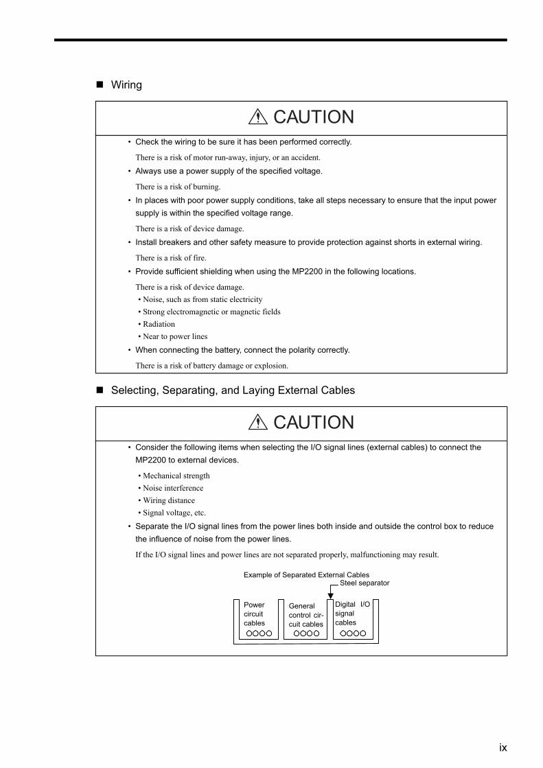
Wiring
Selecting, Separating, and Laying External Cables
• Check the wiring to be sure it has been performed correctly.
There is a risk of motor run-away, injury, or an accident.
• Always use a power supply of the specified voltage.
There is a risk of burning.
• In places with poor power supply conditions, take all steps necessary to ensure that the input power supply is within the specified voltage range.
There is a risk of device damage.
• Install breakers and other safety measure to provide protection against shorts in external wiring.
There is a risk of fire.
• Provide sufficient shielding when using the MP2200 in the following locations.
There is a risk of device damage.• Noise, such as from static electricity• Strong electromagnetic or magnetic fields• Radiation• Near to power lines
• When connecting the battery, connect the polarity correctly.
There is a risk of battery damage or explosion.
• Consider the following items when selecting the I/O signal lines (external cables) to connect the MP2200 to external devices.
• Mechanical strength• Noise interference• Wiring distance• Signal voltage, etc.
• Separate the I/O signal lines from the power lines both inside and outside the control box to reduce the influence of noise from the power lines.
If the I/O signal lines and power lines are not separated properly, malfunctioning may result.
CAUTION
CAUTION
鉄板製のセパレータ
ディジタル入出力信号ケーブル
一般制御回路のケーブル
動力回路のケーブル
外部配線の分離例Example of Separated External CablesSteel separator
Powercircuit cables
Generalcontrol cir-cuit cables
Digital I/Osignal cables
x
Maintenance and Inspection Precautions
Disposal Precautions
• Do not attempt to disassemble the MP2200.
There is a risk of electrical shock or injury.
• Do not change wiring while power is being supplied.
There is a risk of electrical shock or injury.
• When replacing the MP2200, restart operation only after transferring the programs and parameters from the old Module to the new Module.
There is a risk of device damage.
• Dispose of the MP2200 as general industrial waste.
CAUTION
CAUTION

xi
CONTENTSUsing this Manual - - - - - - - - - - - - - - - - - - - - - - - - - - - - - - - - - - - - - - - - - - - - - - - - - - - - - - - iiiSafety Information - - - - - - - - - - - - - - - - - - - - - - - - - - - - - - - - - - - - - - - - - - - - - - - - - - - - - - - viSafety Precautions - - - - - - - - - - - - - - - - - - - - - - - - - - - - - - - - - - - - - - - - - - - - - - - - - - - - - - vii
1 Outline of MP22001.1 Features - - - - - - - - - - - - - - - - - - - - - - - - - - - - - - - - - - - - - - - - - - - - - - - - - - - 1-2
1.2 Module Appearance - - - - - - - - - - - - - - - - - - - - - - - - - - - - - - - - - - - - - - - - - - - 1-31.2.1 Basic Unit - - - - - - - - - - - - - - - - - - - - - - - - - - - - - - - - - - - - - - - - - - - - - - - - - - - - - - - - - - - - 1-31.2.2 Modules - - - - - - - - - - - - - - - - - - - - - - - - - - - - - - - - - - - - - - - - - - - - - - - - - - - - - - - - - - - - - 1-4
2 System Configuration2.1 System Configuration - - - - - - - - - - - - - - - - - - - - - - - - - - - - - - - - - - - - - - - - - - 2-2
2.1.1 Basic System Configuration - - - - - - - - - - - - - - - - - - - - - - - - - - - - - - - - - - - - - - - - - - - - - - - 2-22.1.2 System Configuration Precautions - - - - - - - - - - - - - - - - - - - - - - - - - - - - - - - - - - - - - - - - - - 2-4
2.2 List of Modules - - - - - - - - - - - - - - - - - - - - - - - - - - - - - - - - - - - - - - - - - - - - - - - 2-52.2.1 MP2200 Modules - - - - - - - - - - - - - - - - - - - - - - - - - - - - - - - - - - - - - - - - - - - - - - - - - - - - - - 2-5
2.3 Devices Connectable to MECHATROLINK - - - - - - - - - - - - - - - - - - - - - - - - - - - 2-6
2.4 Cables and Accessories - - - - - - - - - - - - - - - - - - - - - - - - - - - - - - - - - - - - - - - - 2-72.4.1 Cables - - - - - - - - - - - - - - - - - - - - - - - - - - - - - - - - - - - - - - - - - - - - - - - - - - - - - - - - - - - - - - 2-72.4.2 Accessories - - - - - - - - - - - - - - - - - - - - - - - - - - - - - - - - - - - - - - - - - - - - - - - - - - - - - - - - - - 2-7
2.5 Software - - - - - - - - - - - - - - - - - - - - - - - - - - - - - - - - - - - - - - - - - - - - - - - - - - - 2-82.5.1 Software for Programming Devices - - - - - - - - - - - - - - - - - - - - - - - - - - - - - - - - - - - - - - - - - - 2-8
3 System Startup3.1 Outline- - - - - - - - - - - - - - - - - - - - - - - - - - - - - - - - - - - - - - - - - - - - - - - - - - - - - 3-2
3.1.1 System Startup Flowchart- - - - - - - - - - - - - - - - - - - - - - - - - - - - - - - - - - - - - - - - - - - - - - - - - 3-23.1.2 System Configuration - - - - - - - - - - - - - - - - - - - - - - - - - - - - - - - - - - - - - - - - - - - - - - - - - - - 3-33.1.3 Device Preparation - - - - - - - - - - - - - - - - - - - - - - - - - - - - - - - - - - - - - - - - - - - - - - - - - - - - - 3-43.1.4 Connecting and Wiring the System - - - - - - - - - - - - - - - - - - - - - - - - - - - - - - - - - - - - - - - - - - 3-63.1.5 Initializing the System - - - - - - - - - - - - - - - - - - - - - - - - - - - - - - - - - - - - - - - - - - - - - - - - - - - 3-83.1.6 Starting the MPE720 - - - - - - - - - - - - - - - - - - - - - - - - - - - - - - - - - - - - - - - - - - - - - - - - - - - 3-11
3.2 Sample Program 1: Manual Operation - - - - - - - - - - - - - - - - - - - - - - - - - - - - - 3-363.2.1 Description - - - - - - - - - - - - - - - - - - - - - - - - - - - - - - - - - - - - - - - - - - - - - - - - - - - - - - - - - - 3-363.2.2 Operation - - - - - - - - - - - - - - - - - - - - - - - - - - - - - - - - - - - - - - - - - - - - - - - - - - - - - - - - - - - 3-373.2.3 Program Details - - - - - - - - - - - - - - - - - - - - - - - - - - - - - - - - - - - - - - - - - - - - - - - - - - - - - - 3-40
3.3 Sample Program 2: Positioning Control - - - - - - - - - - - - - - - - - - - - - - - - - - - - 3-473.3.1 Description - - - - - - - - - - - - - - - - - - - - - - - - - - - - - - - - - - - - - - - - - - - - - - - - - - - - - - - - - - 3-473.3.2 Operation - - - - - - - - - - - - - - - - - - - - - - - - - - - - - - - - - - - - - - - - - - - - - - - - - - - - - - - - - - - 3-483.3.3 Program Details - - - - - - - - - - - - - - - - - - - - - - - - - - - - - - - - - - - - - - - - - - - - - - - - - - - - - - 3-50
3.4 Sample Program 3: Phase Control with an Electronic Shaft - - - - - - - - - - - - - - 3-523.4.1 Description - - - - - - - - - - - - - - - - - - - - - - - - - - - - - - - - - - - - - - - - - - - - - - - - - - - - - - - - - - 3-52
xii
3.4.2 Operation- - - - - - - - - - - - - - - - - - - - - - - - - - - - - - - - - - - - - - - - - - - - - - - - - - - - - - - - - - - - 3-533.4.3 Program Details - - - - - - - - - - - - - - - - - - - - - - - - - - - - - - - - - - - - - - - - - - - - - - - - - - - - - - - 3-55
3.5 Sample Program 4: Phase Control with an Electronic Cam- - - - - - - - - - - - - - - 3-573.5.1 Description- - - - - - - - - - - - - - - - - - - - - - - - - - - - - - - - - - - - - - - - - - - - - - - - - - - - - - - - - - - 3-573.5.2 Operation- - - - - - - - - - - - - - - - - - - - - - - - - - - - - - - - - - - - - - - - - - - - - - - - - - - - - - - - - - - - 3-583.5.3 Program Details - - - - - - - - - - - - - - - - - - - - - - - - - - - - - - - - - - - - - - - - - - - - - - - - - - - - - - - 3-60
4 Module Specifications4.1 General Specifications - - - - - - - - - - - - - - - - - - - - - - - - - - - - - - - - - - - - - - - - - 4-3
4.1.1 Hardware Specifications - - - - - - - - - - - - - - - - - - - - - - - - - - - - - - - - - - - - - - - - - - - - - - - - - -4-34.1.2 Function List - - - - - - - - - - - - - - - - - - - - - - - - - - - - - - - - - - - - - - - - - - - - - - - - - - - - - - - - - -4-4
4.2 Base Unit- - - - - - - - - - - - - - - - - - - - - - - - - - - - - - - - - - - - - - - - - - - - - - - - - - - 4-54.2.1 Outline of Functions - - - - - - - - - - - - - - - - - - - - - - - - - - - - - - - - - - - - - - - - - - - - - - - - - - - - -4-54.2.2 LED Indicators - - - - - - - - - - - - - - - - - - - - - - - - - - - - - - - - - - - - - - - - - - - - - - - - - - - - - - - - -4-54.2.3 Hardware Specifications - - - - - - - - - - - - - - - - - - - - - - - - - - - - - - - - - - - - - - - - - - - - - - - - - -4-6
4.3 CPU-01 Module - - - - - - - - - - - - - - - - - - - - - - - - - - - - - - - - - - - - - - - - - - - - - - 4-74.3.1 Outline of Functions - - - - - - - - - - - - - - - - - - - - - - - - - - - - - - - - - - - - - - - - - - - - - - - - - - - - -4-74.3.2 LED Indicators and Switch Settings - - - - - - - - - - - - - - - - - - - - - - - - - - - - - - - - - - - - - - - - - -4-74.3.3 Hardware Specifications - - - - - - - - - - - - - - - - - - - - - - - - - - - - - - - - - - - - - - - - - - - - - - - - - -4-94.3.4 Functions and Specifications - - - - - - - - - - - - - - - - - - - - - - - - - - - - - - - - - - - - - - - - - - - - - -4-10
4.4 SVB-01 Module - - - - - - - - - - - - - - - - - - - - - - - - - - - - - - - - - - - - - - - - - - - - - 4-134.4.1 Outline of Functions - - - - - - - - - - - - - - - - - - - - - - - - - - - - - - - - - - - - - - - - - - - - - - - - - - - - 4-134.4.2 LED Indicators and Switch Settings - - - - - - - - - - - - - - - - - - - - - - - - - - - - - - - - - - - - - - - - - 4-134.4.3 Hardware Specifications - - - - - - - - - - - - - - - - - - - - - - - - - - - - - - - - - - - - - - - - - - - - - - - - - 4-154.4.4 Function Lists- - - - - - - - - - - - - - - - - - - - - - - - - - - - - - - - - - - - - - - - - - - - - - - - - - - - - - - - - 4-16
4.5 SVA-01 Module - - - - - - - - - - - - - - - - - - - - - - - - - - - - - - - - - - - - - - - - - - - - - 4-184.5.1 Outline of Functions - - - - - - - - - - - - - - - - - - - - - - - - - - - - - - - - - - - - - - - - - - - - - - - - - - - - 4-184.5.2 LED Indicators and Switch Settings - - - - - - - - - - - - - - - - - - - - - - - - - - - - - - - - - - - - - - - - - 4-184.5.3 Hardware Specifications - - - - - - - - - - - - - - - - - - - - - - - - - - - - - - - - - - - - - - - - - - - - - - - - - 4-194.5.4 Function Lists- - - - - - - - - - - - - - - - - - - - - - - - - - - - - - - - - - - - - - - - - - - - - - - - - - - - - - - - - 4-20
4.6 LIO-01 Module - - - - - - - - - - - - - - - - - - - - - - - - - - - - - - - - - - - - - - - - - - - - - - 4-224.6.1 Outline of Functions - - - - - - - - - - - - - - - - - - - - - - - - - - - - - - - - - - - - - - - - - - - - - - - - - - - - 4-224.6.2 LED Indicators and Switch Settings - - - - - - - - - - - - - - - - - - - - - - - - - - - - - - - - - - - - - - - - - 4-224.6.3 Hardware Specifications - - - - - - - - - - - - - - - - - - - - - - - - - - - - - - - - - - - - - - - - - - - - - - - - - 4-24
4.7 LIO-02 Module - - - - - - - - - - - - - - - - - - - - - - - - - - - - - - - - - - - - - - - - - - - - - - 4-254.7.1 Outline of Functions - - - - - - - - - - - - - - - - - - - - - - - - - - - - - - - - - - - - - - - - - - - - - - - - - - - - 4-254.7.2 LED Indicators and Switch Settings - - - - - - - - - - - - - - - - - - - - - - - - - - - - - - - - - - - - - - - - - 4-254.7.3 Hardware Specifications - - - - - - - - - - - - - - - - - - - - - - - - - - - - - - - - - - - - - - - - - - - - - - - - - 4-27
4.8 LIO-01 and LIO-02 Module Counter Functions - - - - - - - - - - - - - - - - - - - - - - - 4-284.8.1 Outline of Functions - - - - - - - - - - - - - - - - - - - - - - - - - - - - - - - - - - - - - - - - - - - - - - - - - - - - 4-284.8.2 Counter Function Details - - - - - - - - - - - - - - - - - - - - - - - - - - - - - - - - - - - - - - - - - - - - - - - - - 4-304.8.3 Electronic Gear Function - - - - - - - - - - - - - - - - - - - - - - - - - - - - - - - - - - - - - - - - - - - - - - - - - 4-334.8.4 Counter Parameters - - - - - - - - - - - - - - - - - - - - - - - - - - - - - - - - - - - - - - - - - - - - - - - - - - - - 4-37

xiii
4.9 LIO-04 Module - - - - - - - - - - - - - - - - - - - - - - - - - - - - - - - - - - - - - - - - - - - - - - 4-404.9.1 Outline of Functions- - - - - - - - - - - - - - - - - - - - - - - - - - - - - - - - - - - - - - - - - - - - - - - - - - - - 4-404.9.2 LED Indicators and Switch Settings- - - - - - - - - - - - - - - - - - - - - - - - - - - - - - - - - - - - - - - - - 4-404.9.3 Hardware Specifications- - - - - - - - - - - - - - - - - - - - - - - - - - - - - - - - - - - - - - - - - - - - - - - - - 4-41
4.10 218IF-01 Module - - - - - - - - - - - - - - - - - - - - - - - - - - - - - - - - - - - - - - - - - - - 4-424.10.1 Outline of Functions- - - - - - - - - - - - - - - - - - - - - - - - - - - - - - - - - - - - - - - - - - - - - - - - - - - 4-424.10.2 LED Indicators and Switch Settings- - - - - - - - - - - - - - - - - - - - - - - - - - - - - - - - - - - - - - - - 4-424.10.3 Hardware Specifications- - - - - - - - - - - - - - - - - - - - - - - - - - - - - - - - - - - - - - - - - - - - - - - - 4-44
4.11 217IF-01 Module- - - - - - - - - - - - - - - - - - - - - - - - - - - - - - - - - - - - - - - - - - - - 4-454.11.1 Outline of Functions - - - - - - - - - - - - - - - - - - - - - - - - - - - - - - - - - - - - - - - - - - - - - - - - - - - 4-454.11.2 LED Indicators and Switch Settings - - - - - - - - - - - - - - - - - - - - - - - - - - - - - - - - - - - - - - - - 4-454.11.3 Hardware Specifications - - - - - - - - - - - - - - - - - - - - - - - - - - - - - - - - - - - - - - - - - - - - - - - - 4-47
4.12 260IF-01 Module - - - - - - - - - - - - - - - - - - - - - - - - - - - - - - - - - - - - - - - - - - - 4-484.12.1 Outline of Functions- - - - - - - - - - - - - - - - - - - - - - - - - - - - - - - - - - - - - - - - - - - - - - - - - - - 4-484.12.2 LED Indicators and Switch Settings- - - - - - - - - - - - - - - - - - - - - - - - - - - - - - - - - - - - - - - - 4-484.12.3 Hardware Specifications- - - - - - - - - - - - - - - - - - - - - - - - - - - - - - - - - - - - - - - - - - - - - - - - 4-50
4.13 261IF-01 Module - - - - - - - - - - - - - - - - - - - - - - - - - - - - - - - - - - - - - - - - - - - 4-524.13.1 Outline of Functions- - - - - - - - - - - - - - - - - - - - - - - - - - - - - - - - - - - - - - - - - - - - - - - - - - - 4-524.13.2 LED Indicators and Switch Settings- - - - - - - - - - - - - - - - - - - - - - - - - - - - - - - - - - - - - - - - 4-524.13.3 Hardware Specifications- - - - - - - - - - - - - - - - - - - - - - - - - - - - - - - - - - - - - - - - - - - - - - - - 4-54
4.14 EXIOIF Module- - - - - - - - - - - - - - - - - - - - - - - - - - - - - - - - - - - - - - - - - - - - - 4-564.14.1 Outline of Functions- - - - - - - - - - - - - - - - - - - - - - - - - - - - - - - - - - - - - - - - - - - - - - - - - - - 4-564.14.2 LED Indicators and Switch Settings- - - - - - - - - - - - - - - - - - - - - - - - - - - - - - - - - - - - - - - - 4-564.14.3 Hardware Specifications- - - - - - - - - - - - - - - - - - - - - - - - - - - - - - - - - - - - - - - - - - - - - - - - 4-56
4.15 External Appearance- - - - - - - - - - - - - - - - - - - - - - - - - - - - - - - - - - - - - - - - - 4-574.15.1 Basic Unit - - - - - - - - - - - - - - - - - - - - - - - - - - - - - - - - - - - - - - - - - - - - - - - - - - - - - - - - - - 4-574.15.2 Mounting Optional Module Connectors - - - - - - - - - - - - - - - - - - - - - - - - - - - - - - - - - - - - - 4-58
5 Mounting and Wiring5.1 Handling the MP2200 - - - - - - - - - - - - - - - - - - - - - - - - - - - - - - - - - - - - - - - - - - 5-2
5.1.1 Mounting the MP2200 - - - - - - - - - - - - - - - - - - - - - - - - - - - - - - - - - - - - - - - - - - - - - - - - - - - 5-25.1.2 Replacing and Adding Optional Modules - - - - - - - - - - - - - - - - - - - - - - - - - - - - - - - - - - - - - - 5-5
5.2 Module Connections - - - - - - - - - - - - - - - - - - - - - - - - - - - - - - - - - - - - - - - - - - - 5-85.2.1 Connecting Power Supply - - - - - - - - - - - - - - - - - - - - - - - - - - - - - - - - - - - - - - - - - - - - - - - - 5-85.2.2 SVB-01 Module Connections - - - - - - - - - - - - - - - - - - - - - - - - - - - - - - - - - - - - - - - - - - - - - 5-115.2.3 SVA-01 Module Connections - - - - - - - - - - - - - - - - - - - - - - - - - - - - - - - - - - - - - - - - - - - - - 5-175.2.4 LIO Module Connections - - - - - - - - - - - - - - - - - - - - - - - - - - - - - - - - - - - - - - - - - - - - - - - - 5-255.2.5 LIO-04 Module Connections - - - - - - - - - - - - - - - - - - - - - - - - - - - - - - - - - - - - - - - - - - - - - - 5-375.2.6 218IF-01 Module Connections - - - - - - - - - - - - - - - - - - - - - - - - - - - - - - - - - - - - - - - - - - - - 5-475.2.7 217IF-01 Module Connections - - - - - - - - - - - - - - - - - - - - - - - - - - - - - - - - - - - - - - - - - - - - 5-515.2.8 260IF-01 Module Connections - - - - - - - - - - - - - - - - - - - - - - - - - - - - - - - - - - - - - - - - - - - - 5-555.2.9 261IF-01 Module Connections - - - - - - - - - - - - - - - - - - - - - - - - - - - - - - - - - - - - - - - - - - - - 5-585.2.10 EXIOIF Module Connections - - - - - - - - - - - - - - - - - - - - - - - - - - - - - - - - - - - - - - - - - - - - 5-61
xiv
6 Basic System Operation6.1 Operating Mode - - - - - - - - - - - - - - - - - - - - - - - - - - - - - - - - - - - - - - - - - - - - - - 6-2
6.1.1 Online Operating Mode - - - - - - - - - - - - - - - - - - - - - - - - - - - - - - - - - - - - - - - - - - - - - - - - - - -6-26.1.2 Offline Stop Mode - - - - - - - - - - - - - - - - - - - - - - - - - - - - - - - - - - - - - - - - - - - - - - - - - - - - - - -6-2
6.2 Startup Sequence and Basic Operation - - - - - - - - - - - - - - - - - - - - - - - - - - - - - 6-36.2.1 DIP Switch Settings - - - - - - - - - - - - - - - - - - - - - - - - - - - - - - - - - - - - - - - - - - - - - - - - - - - - -6-36.2.2 Indicator Patterns - - - - - - - - - - - - - - - - - - - - - - - - - - - - - - - - - - - - - - - - - - - - - - - - - - - - - - -6-46.2.3 Startup Sequence - - - - - - - - - - - - - - - - - - - - - - - - - - - - - - - - - - - - - - - - - - - - - - - - - - - - - - -6-5
6.3 User Program- - - - - - - - - - - - - - - - - - - - - - - - - - - - - - - - - - - - - - - - - - - - - - - - 6-76.3.1 Drawings (DWGs)- - - - - - - - - - - - - - - - - - - - - - - - - - - - - - - - - - - - - - - - - - - - - - - - - - - - - - -6-76.3.2 Execution Control of Drawings - - - - - - - - - - - - - - - - - - - - - - - - - - - - - - - - - - - - - - - - - - - - - -6-86.3.3 Motion Programs - - - - - - - - - - - - - - - - - - - - - - - - - - - - - - - - - - - - - - - - - - - - - - - - - - - - - - 6-116.3.4 Functions- - - - - - - - - - - - - - - - - - - - - - - - - - - - - - - - - - - - - - - - - - - - - - - - - - - - - - - - - - - - 6-19
6.4 Registers - - - - - - - - - - - - - - - - - - - - - - - - - - - - - - - - - - - - - - - - - - - - - - - - - - 6-206.4.1 Data Types - - - - - - - - - - - - - - - - - - - - - - - - - - - - - - - - - - - - - - - - - - - - - - - - - - - - - - - - - - 6-206.4.2 Types of Registers - - - - - - - - - - - - - - - - - - - - - - - - - - - - - - - - - - - - - - - - - - - - - - - - - - - - - 6-236.4.3 Register Designation Methods - - - - - - - - - - - - - - - - - - - - - - - - - - - - - - - - - - - - - - - - - - - - - 6-266.4.4 Subscripts i and j - - - - - - - - - - - - - - - - - - - - - - - - - - - - - - - - - - - - - - - - - - - - - - - - - - - - - - 6-27
6.5 Self-configuration - - - - - - - - - - - - - - - - - - - - - - - - - - - - - - - - - - - - - - - - - - - - 6-296.5.1 Overview of Self-configuration - - - - - - - - - - - - - - - - - - - - - - - - - - - - - - - - - - - - - - - - - - - - - 6-296.5.2 SVB-01 Modules - - - - - - - - - - - - - - - - - - - - - - - - - - - - - - - - - - - - - - - - - - - - - - - - - - - - - - 6-306.5.3 SVA-01 Modules- - - - - - - - - - - - - - - - - - - - - - - - - - - - - - - - - - - - - - - - - - - - - - - - - - - - - - - 6-396.5.4 LIO-01 Modules - - - - - - - - - - - - - - - - - - - - - - - - - - - - - - - - - - - - - - - - - - - - - - - - - - - - - - - 6-406.5.5 LIO-02 Modules - - - - - - - - - - - - - - - - - - - - - - - - - - - - - - - - - - - - - - - - - - - - - - - - - - - - - - - 6-416.5.6 LIO-04 Modules - - - - - - - - - - - - - - - - - - - - - - - - - - - - - - - - - - - - - - - - - - - - - - - - - - - - - - - 6-426.5.7 218IF-01 Modules- - - - - - - - - - - - - - - - - - - - - - - - - - - - - - - - - - - - - - - - - - - - - - - - - - - - - - 6-436.5.8 217IF-01 Modules- - - - - - - - - - - - - - - - - - - - - - - - - - - - - - - - - - - - - - - - - - - - - - - - - - - - - - 6-446.5.9 260IF-01 Modules- - - - - - - - - - - - - - - - - - - - - - - - - - - - - - - - - - - - - - - - - - - - - - - - - - - - - - 6-466.5.10 261IF-01 Modules- - - - - - - - - - - - - - - - - - - - - - - - - - - - - - - - - - - - - - - - - - - - - - - - - - - - - 6-47
6.6 Setting and Changing User-defined Files or Data - - - - - - - - - - - - - - - - - - - - - 6-486.6.1 Saving User-defined Files or Data - - - - - - - - - - - - - - - - - - - - - - - - - - - - - - - - - - - - - - - - - - 6-486.6.2 Setting and Changing the Scan Times - - - - - - - - - - - - - - - - - - - - - - - - - - - - - - - - - - - - - - - 6-486.6.3 Setting and Changing the Module Configuration Definition - - - - - - - - - - - - - - - - - - - - - - - - - 6-49
7 Maintenance and Inspection7.1 Inspection Items - - - - - - - - - - - - - - - - - - - - - - - - - - - - - - - - - - - - - - - - - - - - - - 7-2
7.1.1 Daily Inspections - - - - - - - - - - - - - - - - - - - - - - - - - - - - - - - - - - - - - - - - - - - - - - - - - - - - - - -7-27.1.2 Regular Inspections - - - - - - - - - - - - - - - - - - - - - - - - - - - - - - - - - - - - - - - - - - - - - - - - - - - - -7-3
7.2 MBU-01/MBU-02 Unit Batteries - - - - - - - - - - - - - - - - - - - - - - - - - - - - - - - - - - - 7-47.2.1 Battery Life - - - - - - - - - - - - - - - - - - - - - - - - - - - - - - - - - - - - - - - - - - - - - - - - - - - - - - - - - - -7-47.2.2 Replacing the Battery - - - - - - - - - - - - - - - - - - - - - - - - - - - - - - - - - - - - - - - - - - - - - - - - - - - -7-4
xv
8 Troubleshooting8.1 Overview of Troubleshooting - - - - - - - - - - - - - - - - - - - - - - - - - - - - - - - - - - - - - 8-2
8.1.1 Troubleshooting Methods - - - - - - - - - - - - - - - - - - - - - - - - - - - - - - - - - - - - - - - - - - - - - - - - - 8-28.1.2 Basic Troubleshooting Flow - - - - - - - - - - - - - - - - - - - - - - - - - - - - - - - - - - - - - - - - - - - - - - - 8-38.1.3 Indicator Errors - - - - - - - - - - - - - - - - - - - - - - - - - - - - - - - - - - - - - - - - - - - - - - - - - - - - - - - - 8-3
8.2 System Errors - - - - - - - - - - - - - - - - - - - - - - - - - - - - - - - - - - - - - - - - - - - - - - - 8-58.2.1 Overview of System Errors- - - - - - - - - - - - - - - - - - - - - - - - - - - - - - - - - - - - - - - - - - - - - - - - 8-58.2.2 Processing Flow When a System Error Occurs - - - - - - - - - - - - - - - - - - - - - - - - - - - - - - - - - 8-68.2.3 Processing Flow for a User Program Error- - - - - - - - - - - - - - - - - - - - - - - - - - - - - - - - - - - - - 8-78.2.4 System Register Configuration - - - - - - - - - - - - - - - - - - - - - - - - - - - - - - - - - - - - - - - - - - - - - 8-8
AppendicesA List of System Registers - - - - - - - - - - - - - - - - - - - - - - - - - - - - - - - - - - - - - - - - - A-2
A.1 System Service Registers- - - - - - - - - - - - - - - - - - - - - - - - - - - - - - - - - - - - - - - - - - - - - - - - - - A-2A.2 Scan Execution Status and Calendar- - - - - - - - - - - - - - - - - - - - - - - - - - - - - - - - - - - - - - - - - - A-5A.3 Program Software Numbers and Remaining Program Memory Capacity - - - - - - - - - - - - - - - - - A-5
INDEX
Revision History
1-1
11
Outline of MP2200
This chapter provides an overview and describes the features of the MP2200 Machine Control-ler.
1.1 Features - - - - - - - - - - - - - - - - - - - - - - - - - - - - - - - - - - - - - - - - - - - - - - - 1-2
1.2 Module Appearance - - - - - - - - - - - - - - - - - - - - - - - - - - - - - - - - - - - - - - - 1-31.2.1 Basic Unit - - - - - - - - - - - - - - - - - - - - - - - - - - - - - - - - - - - - - - - - - - - - - - - - - - - - - - - 1-31.2.2 Modules - - - - - - - - - - - - - - - - - - - - - - - - - - - - - - - - - - - - - - - - - - - - - - - - - - - - - - - - 1-4
1 Outline of MP2200
1-2
1.1 FeaturesThe MP2200 is a high-performance, multi-axis Machine Controller for flexible system construction. In addition to I/O and Communication Modules, it has a wide range of Optional Modules, including various Motion Mod-ules that support a variety of motor drives. It provides ideal motion control for a range of machines, from stand-alone machines to FA systems.
(1) Flexibility• With an option slot configuration that enables expansion to 35 slots, Optional Modules can be selected
freely and the optimum system can be built for your machine.
(2) High Performance• Control characteristics have been improved by increasing the CPU and Motion Network
(MECHATROLINK-II) speed.• Completely synchronous operation can be achieved for up to 256 axes. • MECHATROLINK-II baud rate: 2.5 times faster than MP920• CPU processing speed: 2.0 times faster than MP920• Larger user memory area
• High-speed (0.5 ms) motion control is now possible.• MECHATROLINK-II enables position control, speed control, torque control, and phase control, and
makes precise synchronous control possible. The control mode can also be changed online, facilitating complicated machine operations. The range of possible motion control applications is increased even further with the Virtual Motion Module (SVR).
• The following open networks are supported when optional Communication Modules are used.• Ethernet• DeviceNet• PROFIBUS
(3) Easy to Use• Machine startup times can be greatly reduced by using the self-configuration function that automatically
detects devices connected to MECHATROLINK and sets the required parameters.• The application program converter can utilize your previous software assets with their accumulated data-
banks of specific knowledge to improve the system further.
(4) Compact• The mounting area has been reduced to half that of the MP920.
1.2 Module Appearance
1-3
1
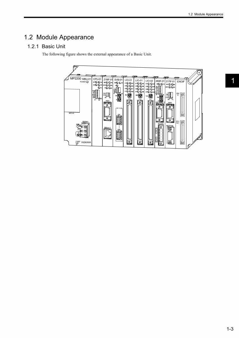
1.2 Module Appearance1.2.1 Basic Unit
The following figure shows the external appearance of a Basic Unit.
MP2200 MBU-01POWER
CPU-01 SVB-01218IF-01 LIO-02LIO-01LIO-01 217IF-01 EXIOIF260IF-01
YASKAWA
1 Outline of MP2200
1.2.2 Modules
1-4
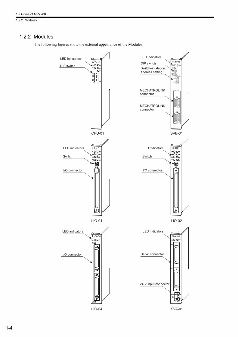
1.2.2 ModulesThe following figures show the external appearance of the Modules.
SVB-01
TX
ERRRUN
SPDSIZEM/S
ONOFF
10
1
M-I/II
CN1
CN2
CPU-01RDY RUN
ERR
BAT
ALM
SUP
OFF ONSW1
MONTEST
INIT
STOP
CNFG
LIO-01 LIO-02
CPU-01 SVB-01
LIO-01 LIO-02
LIO-04
LIO-04
RUN FU
CN2
CN1
SVA-01
SVA-01RUN
CH1
CH2
DC IN
ON
+24V
ERR
LED indicators
Switches (station address setting)
DIP switch
MECHATROLINK connector
MECHATROLINK connector
LED indicators
DIP switch
LED indicators
Switch
I/O connector
LED indicators
Switch
I/O connector
LED indicators
I/O connector
LED indicators
Servo connector
24-V input connector

1.2 Module Appearance
1-5
1
(10Base-T)
(RS-232C)
(RS-232C) (RS-232C)
(RS-232C)
(RS-422/485)
260IF-01 261IF-01
PROFIBUS
217IF-01218IF-01
218IF-01 217IF-01
260IF-01 261IF-01
EXIOIF
EXIOIF
LED indicators
Switch
Serial connector
Ethernet connector
LED indicators
Switches
Serial connector
DeviceNet connector
Serial connector
PROFIBUS connector
LED indicators
Switch
Serial connector
Serial connector
LED indicators
Switches
External input connector
External output connector
2-1
2
2System Configuration
This chapter explains the product information required to build MP2200 systems.
2.1 System Configuration - - - - - - - - - - - - - - - - - - - - - - - - - - - - - - - - - - - - - - 2-22.1.1 Basic System Configuration - - - - - - - - - - - - - - - - - - - - - - - - - - - - - - - - - - - - - - - - - - 2-22.1.2 System Configuration Precautions - - - - - - - - - - - - - - - - - - - - - - - - - - - - - - - - - - - - - 2-4
2.2 List of Modules - - - - - - - - - - - - - - - - - - - - - - - - - - - - - - - - - - - - - - - - - - - 2-52.2.1 MP2200 Modules - - - - - - - - - - - - - - - - - - - - - - - - - - - - - - - - - - - - - - - - - - - - - - - - - 2-5
2.3 Devices Connectable to MECHATROLINK - - - - - - - - - - - - - - - - - - - - - - - 2-6
2.4 Cables and Accessories - - - - - - - - - - - - - - - - - - - - - - - - - - - - - - - - - - - - 2-72.4.1 Cables - - - - - - - - - - - - - - - - - - - - - - - - - - - - - - - - - - - - - - - - - - - - - - - - - - - - - - - - - 2-72.4.2 Accessories - - - - - - - - - - - - - - - - - - - - - - - - - - - - - - - - - - - - - - - - - - - - - - - - - - - - - 2-7
2.5 Software - - - - - - - - - - - - - - - - - - - - - - - - - - - - - - - - - - - - - - - - - - - - - - - 2-82.5.1 Software for Programming Devices - - - - - - - - - - - - - - - - - - - - - - - - - - - - - - - - - - - - - 2-8
2 System Configuration
2.1.1 Basic System Configuration
2-2
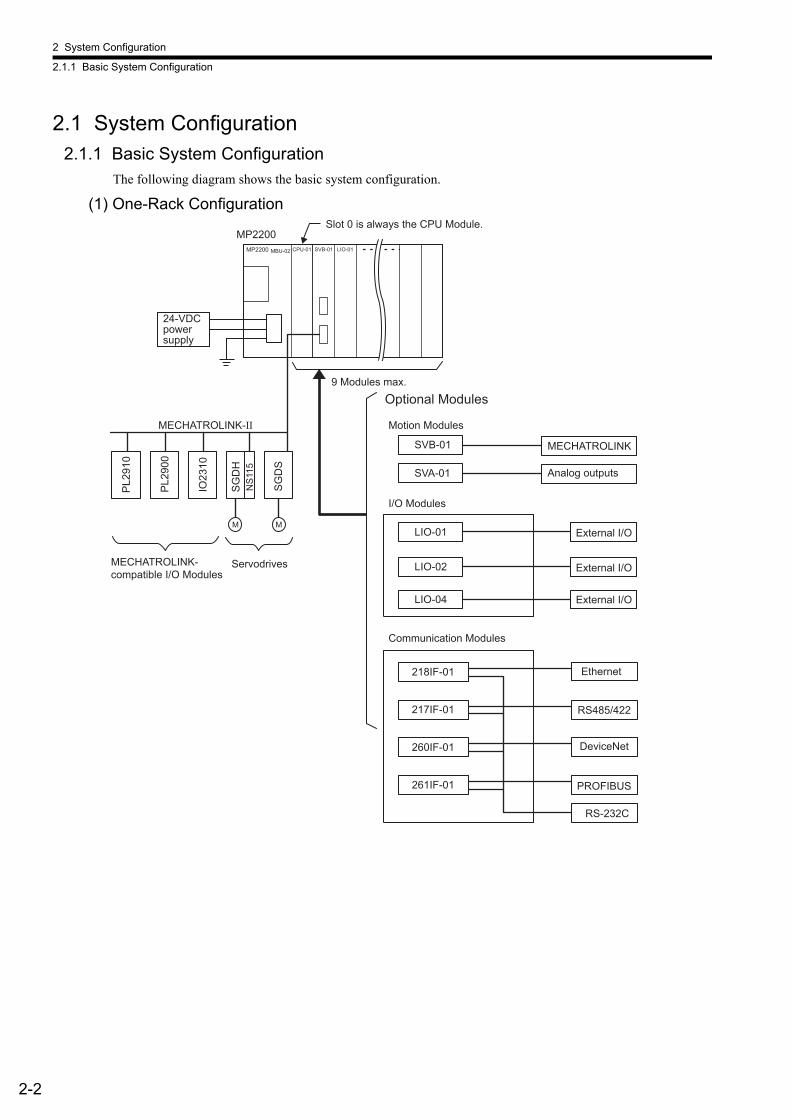
2.1 System Configuration2.1.1 Basic System Configuration
The following diagram shows the basic system configuration.
(1) One-Rack Configuration
SGD
S
M
IO23
10
PL29
00
PL29
10
LIO-02
LIO-01
SVB-01
261IF-01
260IF-01
217IF-01
218IF-01
LIO-04
SVA-01
Ethernet
RS-232C
PROFIBUS
DeviceNet
RS485/422
NS1
15SG
DH
M
MP2200
MECHATROLINK-II
CPU-01MBU-02MP2200 SVB-01 LIO-01
MECHATROLINK
I/O Modules
9 Modules max.
Motion Modules
24-VDC power supply
Communication Modules
Optional Modules
MECHATROLINK-compatible I/O Modules
Servodrives External I/O
External I/O
External I/O
Analog outputs
Slot 0 is always the CPU Module.
2.1 System Configuration
2-3
2
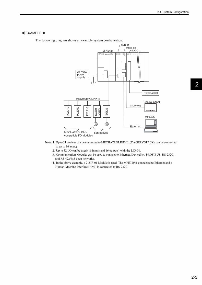
The following diagram shows an example system configuration.
Note: 1. Up to 21 devices can be connected to MECHATROLINK-II. (The SERVOPACKs can be connected to up to 16 axes.)
2. Up to 32 I/O can be used (16 inputs and 16 outputs) with the LIO-01.3. Communication Modules can be used to connect to Ethernet, DeviceNet, PROFIBUS, RS-232C,
and RS-422/485 open networks.4. In the above example, a 218IF-01 Module is used. The MPE720 is connected to Ethernet and a
Human-Machine Interface (HMI) is connected to RS-232C.
EXAMPLE
SGD
S
M
IO23
10
PL29
00
PL29
10
NS1
15SG
DH
M
MP2200
MECHATROLINK-II
CPU-01MBU-02MP2200 SVB-01
SVB-01
218IF
218IF-01
-01LIO-01
LIO-01
Ethernet
RS-232C
MPE720
24-VDC power supply
MECHATROLINK-compatible I/O Modules
Servodrives
External I/O
Control panel

2 System Configuration
2.1.2 System Configuration Precautions
2-4
(2) Maximum Four-Rack Configuration
* A distributed I/O function is provided by the SVB-01 Modules through MECHATROLINK communication.
2.1.2 System Configuration PrecautionsThe following precautions must be followed when designing a system using the MP2200.
• Use the connecting cables and connectors recommended by Yaskawa. Yaskawa has a range of cables. Always check the device to be used and select the correct cable for the device.
• Different SERVOPACKs are connected to MECHATROLINK-I and MECHATROLINK-II. Refer to the list and select the appropriate SERVOPACKs.
• The user must supply the 24-VDC power supply.• The battery backs up M registers, system registers, and trace memory. Always save the program to flash
memory whenever it is input or changed.
LIO
-01
LIO
-02
218I
F-01
260I
F-01
261I
F-01
217I
F-01
SVA-
01
External I/O Modules
Communication Modules
Motion Modules
Optional Modules
External I/O
External I/O
Ethernet
RS-232C
PROFIBUS
DeviceNet
RS-422/485
SERVOPACK
SVB-
01MPE720
MMI
LIO
-04
SVB-
01
Distributed I/O Modules *
External input
External output
24 VDCor
100/200VAC
Slot 8Slot 0 (always CPU Module)
Slot 1 Slot 9
Slot 1 Slot 9
Slot 1 Slot 9
M
PG
2.2 List of Modules
2-5
2
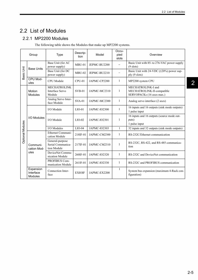
2.2 List of Modules2.2.1 MP2200 Modules
The following table shows the Modules that make up MP2200 systems.
Group Type Descrip-tion Model
Occu-pied slots
Overview
Basi
c U
nit
Base Units
Base Unit (for AC power supply) MBU-01 JEPMC-BU2200 − Basic Unit with 85- to 276-VAC power supply
(9 slots)Base Unit (for DC power supply) MBU-02 JEPMC-BU2210 − Basic Unit with 24-VDC (±20%) power sup-
ply (9 slots)CPU Mod-ules CPU Module CPU-01 JAPMC-CP2200 1 MP2200 system CPU
Opt
iona
l Mod
ules
Motion Modules
MECHATROLINK Interface Servo Module
SVB-01 JAPMC-MC2310 1MECHATROLINK-I and MECHATROLINK-II-compatible SERVOPACKs (16 axes max.)
Analog Servo Inter-face Module SVA-01 JAPMC-MC2300 1 Analog servo interface (2 axes)
I/O Modules
I/O Module LIO-01 JAPMC-IO2300 1 16 inputs and 16 outputs (sink mode outputs)1 pulse input
I/O Module LIO-02 JAPMC-IO2301 116 inputs and 16 outputs (source mode out-puts)1 pulse input
I/O Modules LIO-04 JAPMC-IO2303 1 32 inputs and 32 outputs (sink mode outputs)
Communi-cation Mod-ules
Ethernet Communi-cation Module 218IF-01 JAPMC-CM2300 1 RS-232C/Ethernet communication
General-purpose Serial Communica-tion Module
217IF-01 JAPMC-CM2310 1 RS-232C, RS-422, and RS-485 communica-tion
DeviceNet Commu-nication Module 260IF-01 JAPMC-IO2320 1 RS-232C and DeviceNet communication
PROFIBUS Com-munication Module 261IF-01 JAPMC-IO2330 1 RS-232C and PROFIBUS communication
Expansion Interface Modules
Connection Inter-face EXIOIF JAPMC-EX2200
1 System bus expansion (maximum 4-Rack con-figuration)

2 System Configuration
2-6
2.3 Devices Connectable to MECHATROLINKThe devices that are compatible with MECHATROLINK and can be connected to the SVB-01 Module are listed below.
(1) SERVOPACKsThe following table shows SERVOPACKs that are compatible with MECHATROLINK and can be connected to the SVB-01 Module.
(2) I/O ModulesThe following table shows Modules that are compatible with MECHATROLINK and can be connected to the SVB-01 Module.
Model Details MECHATROLINK-I MECHATROLINK-IISGD- NSGDB- AN
MECHATROLINK-I compatible AC SERVOPACKs ×
SGDH- EJUSP-NS100
Σ-II Series SGDH Servodrives NS100 MECHATROLINK-I Interface Unit ×
SGDH- EJUSP-NS115
Σ-II Series SGDH Servodrives NS115 MECHATROLINK-II Interface Unit
SGDS- 1 Σ-III Series AC Servodrives
Model Details MECHATROLINK-I MECHATROLINK-II
JEPMC-IO350 64-point I/O Module24 VDC, 64 inputs, 64 outputs ×
JAMSC-120DDI34330 DC Input Module12/24 VDC, 16 inputs ×
JAMSC-120DDO34340 DC Output Module12/24 VDC, 16 outputs ×
JAMSC-120DAI53330 AC Input Module100 VAC, 8 inputs ×
JAMSC-120DAI73330 AC Input Module200 VAC, 8 inputs ×
JAMSC-120DAO83330 AC Output Module100/200 VAC, 8 outputs ×
JAMSC-120DRA83030 Relay ModuleWide voltage range relay contacts, 8 outputs ×
JAMSC-120AVI02030 A/D ModuleAnalog inputs, −10 to 10 V, 4 channels ×
JAMSC-120AVO01030 D/A ModuleAnalog outputs, −10 to 10 V, 2 channels ×
JAMSC-120EHC21140 Counter ModuleReversible counter, 2 channels ×
JAMSC-120MMB20230 Pulse Output ModulePulse output, 2 channels ×
JEPMC-IO2310 64-point I/O Module24 VDC, 64 inputs, 64 outputs
JEPMC-PL2900 Counter ModuleReversible counter, 2 channels
JEPMC-PL2910 Pulse Output ModulePulse output, 2 channels
JEPMC-AN2900 A/D ModuleAnalog inputs, −10 to 10 V, 4 channels
JEPMC-AN2910 D/A ModuleAnalog outputs, −10 to 10 V, 2 channels
JAPMC-MC2310 SVB-01 Motion ModuleJEVSA-YV250 MYVIS YV250 Machine Vision System
JEPMC-MC400 MP940 Motion Controller ×
2.4 Cables and Accessories
2-7
2
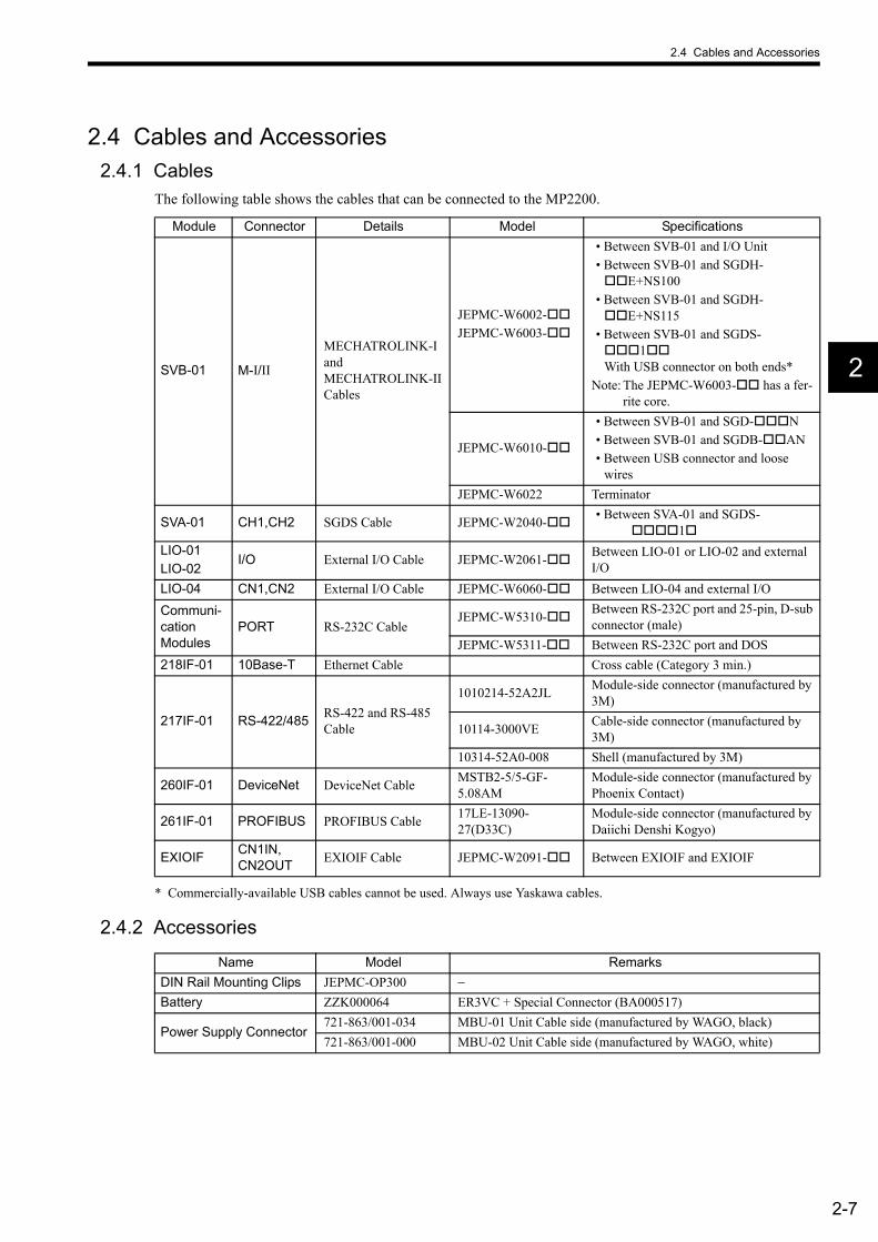
2.4 Cables and Accessories2.4.1 Cables
The following table shows the cables that can be connected to the MP2200.
* Commercially-available USB cables cannot be used. Always use Yaskawa cables.
2.4.2 Accessories
Module Connector Details Model Specifications
SVB-01 M-I/II
MECHATROLINK-I and MECHATROLINK-II Cables
JEPMC-W6002-JEPMC-W6003-
• Between SVB-01 and I/O Unit• Between SVB-01 and SGDH-
E+NS100• Between SVB-01 and SGDH-
E+NS115• Between SVB-01 and SGDS-
1 With USB connector on both ends*
Note: The JEPMC-W6003- has a fer-rite core.
JEPMC-W6010-
• Between SVB-01 and SGD- N• Between SVB-01 and SGDB- AN• Between USB connector and loose
wiresJEPMC-W6022 Terminator
SVA-01 CH1,CH2 SGDS Cable JEPMC-W2040- • Between SVA-01 and SGDS-1
LIO-01LIO-02
I/O External I/O Cable JEPMC-W2061- Between LIO-01 or LIO-02 and external I/O
LIO-04 CN1,CN2 External I/O Cable JEPMC-W6060- Between LIO-04 and external I/O
Communi-cation Modules
PORT RS-232C CableJEPMC-W5310- Between RS-232C port and 25-pin, D-sub
connector (male)JEPMC-W5311- Between RS-232C port and DOS
218IF-01 10Base-T Ethernet Cable Cross cable (Category 3 min.)
217IF-01 RS-422/485 RS-422 and RS-485 Cable
1010214-52A2JL Module-side connector (manufactured by 3M)
10114-3000VE Cable-side connector (manufactured by 3M)
10314-52A0-008 Shell (manufactured by 3M)
260IF-01 DeviceNet DeviceNet Cable MSTB2-5/5-GF-5.08AM
Module-side connector (manufactured by Phoenix Contact)
261IF-01 PROFIBUS PROFIBUS Cable 17LE-13090-27(D33C)
Module-side connector (manufactured by Daiichi Denshi Kogyo)
EXIOIF CN1IN,CN2OUT EXIOIF Cable JEPMC-W2091- Between EXIOIF and EXIOIF
Name Model RemarksDIN Rail Mounting Clips JEPMC-OP300 −Battery ZZK000064 ER3VC + Special Connector (BA000517)
Power Supply Connector721-863/001-034 MBU-01 Unit Cable side (manufactured by WAGO, black)721-863/001-000 MBU-02 Unit Cable side (manufactured by WAGO, white)

2 System Configuration
2.5.1 Software for Programming Devices
2-8
2.5 Software2.5.1 Software for Programming Devices
* Older versions cannot be used. Always use Ver. 5.10 or later.
Name Model RemarksMPE720 CPMC-MPE720 (Ver. 5.10 or later)* CD-ROM (1 disk)
3-1
3
3System Startup
This chapter describes the startup procedure for the MP2200 system and provides sample pro-grams for typical operation and control.
3.1 Outline - - - - - - - - - - - - - - - - - - - - - - - - - - - - - - - - - - - - - - - - - - - - - - - - - 3-23.1.1 System Startup Flowchart - - - - - - - - - - - - - - - - - - - - - - - - - - - - - - - - - - - - - - - - - - - - 3-23.1.2 System Configuration - - - - - - - - - - - - - - - - - - - - - - - - - - - - - - - - - - - - - - - - - - - - - - 3-33.1.3 Device Preparation - - - - - - - - - - - - - - - - - - - - - - - - - - - - - - - - - - - - - - - - - - - - - - - - 3-43.1.4 Connecting and Wiring the System - - - - - - - - - - - - - - - - - - - - - - - - - - - - - - - - - - - - - 3-63.1.5 Initializing the System - - - - - - - - - - - - - - - - - - - - - - - - - - - - - - - - - - - - - - - - - - - - - - 3-83.1.6 Starting the MPE720 - - - - - - - - - - - - - - - - - - - - - - - - - - - - - - - - - - - - - - - - - - - - - - 3-11
3.2 Sample Program 1: Manual Operation - - - - - - - - - - - - - - - - - - - - - - - - - 3-363.2.1 Description - - - - - - - - - - - - - - - - - - - - - - - - - - - - - - - - - - - - - - - - - - - - - - - - - - - - - 3-363.2.2 Operation - - - - - - - - - - - - - - - - - - - - - - - - - - - - - - - - - - - - - - - - - - - - - - - - - - - - - - 3-373.2.3 Program Details - - - - - - - - - - - - - - - - - - - - - - - - - - - - - - - - - - - - - - - - - - - - - - - - - 3-40
3.3 Sample Program 2: Positioning Control - - - - - - - - - - - - - - - - - - - - - - - - 3-473.3.1 Description - - - - - - - - - - - - - - - - - - - - - - - - - - - - - - - - - - - - - - - - - - - - - - - - - - - - - 3-473.3.2 Operation - - - - - - - - - - - - - - - - - - - - - - - - - - - - - - - - - - - - - - - - - - - - - - - - - - - - - - 3-483.3.3 Program Details - - - - - - - - - - - - - - - - - - - - - - - - - - - - - - - - - - - - - - - - - - - - - - - - - 3-50
3.4 Sample Program 3: Phase Control with an Electronic Shaft - - - - - - - - - - 3-523.4.1 Description - - - - - - - - - - - - - - - - - - - - - - - - - - - - - - - - - - - - - - - - - - - - - - - - - - - - - 3-523.4.2 Operation - - - - - - - - - - - - - - - - - - - - - - - - - - - - - - - - - - - - - - - - - - - - - - - - - - - - - - 3-533.4.3 Program Details - - - - - - - - - - - - - - - - - - - - - - - - - - - - - - - - - - - - - - - - - - - - - - - - - 3-55
3.5 Sample Program 4: Phase Control with an Electronic Cam - - - - - - - - - - - 3-573.5.1 Description - - - - - - - - - - - - - - - - - - - - - - - - - - - - - - - - - - - - - - - - - - - - - - - - - - - - - 3-573.5.2 Operation - - - - - - - - - - - - - - - - - - - - - - - - - - - - - - - - - - - - - - - - - - - - - - - - - - - - - - 3-583.5.3 Program Details - - - - - - - - - - - - - - - - - - - - - - - - - - - - - - - - - - - - - - - - - - - - - - - - - 3-60

3 System Startup
3.1.1 System Startup Flowchart
3-2
3.1 OutlineThis section explains the system startup procedure when the sample program on the MPE720 installation disk is used. Details on the machine system design have been omitted here.
3.1.1 System Startup FlowchartThe system startup procedure is outlined below.Refer to the references given in the right-hand column for information on each step.
1. Prepare the equipment needed for testing. 3.1.3 Device Preparation
2. Mount the 218IF-01 to the MP2200. Chapter 5 Mounting and Wiring
3. Connect the MPE720, and wire the Servomotors and SERVOPACKs. 3.1.4 Connecting and Wiring the System
4. Initialize the SERVOPACKs. 3.1.5 Initializing the System
5. The connected devices are automatically con-firmed. 3.1.5 Initializing the System
6. Install the sample programs and start the MPE720. 3.1.6 Starting the MPE720
7. Save the sample program and configuration defi-nitions to flash memory. 3.1.6 Starting the MPE720
8. Execute the program and check the test opera-tion.
3.2 Sample Program 1: Manual Operation3.3 Sample Program 2: Positioning Control3.4 Sample Program 3: Phase Control with an Electronic Shaft3.5 Sample Program 4: Phase Control with an Electronic Cam
3.1 Outline
3-3
3
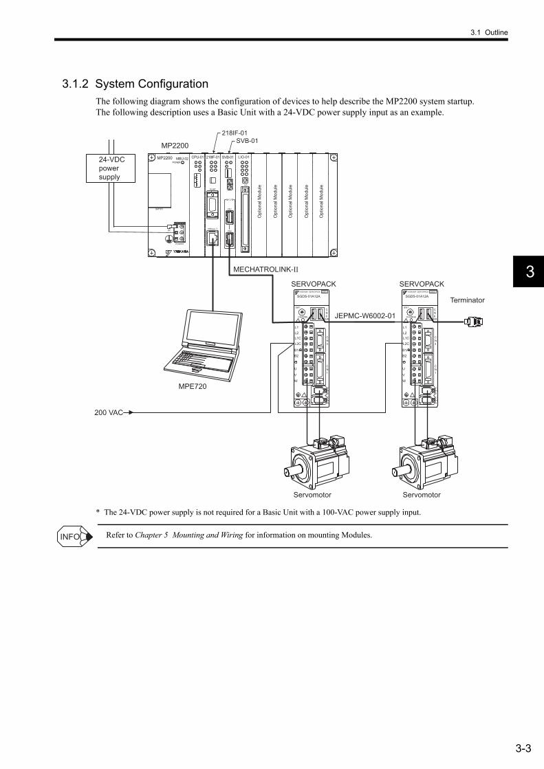
3.1.2 System ConfigurationThe following diagram shows the configuration of devices to help describe the MP2200 system startup. The following description uses a Basic Unit with a 24-VDC power supply input as an example.
* The 24-VDC power supply is not required for a Basic Unit with a 100-VAC power supply input.
Refer to Chapter 5 Mounting and Wiring for information on mounting Modules.
MPE720
YASKAWA SERVOPACK 200V
SGDS-01A12A
SW1
CHARGE
CN3
A/B
CN1
CN2
CN4
L1L2
L2CL1C
B1/B2
U
V
W
CN6
YASKAWA SERVOPACK 200V
SGDS-01A12A
SW1
CHARGE
CN3
A/B
CN1
CN2
CN4
L1L2
L2CL1C
B1/B2
U
V
W
CN6
MECHATROLINK-II
JEPMC-W6002-01
200 VAC
MP2200 MBU-02 CPU-01 SVB-01218IF-01
CN1
CN2
BATTEY
POWER
DC
PORT
10Base-T
POWER
LIO-01
I/O
MP2200SVB-01
218IF-01
SERVOPACK SERVOPACK
Servomotor Servomotor
Opt
iona
l Mod
ule
Opt
iona
l Mod
ule
Opt
iona
l Mod
ule
Opt
iona
l Mod
ule
Opt
iona
l Mod
ule
Terminator
24-VDC power supply
INFO
3 System Startup
3.1.3 Device Preparation
3-4
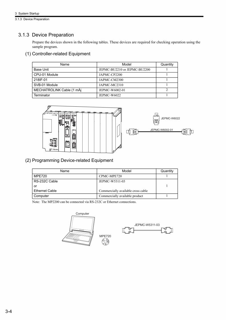
3.1.3 Device PreparationPrepare the devices shown in the following tables. These devices are required for checking operation using the sample program.
(1) Controller-related Equipment
(2) Programming Device-related Equipment
Note: The MP2200 can be connected via RS-232C or Ethernet connections.
Name Model QuantityBase Unit JEPMC-BU2210 or JEPMC-BU2200 1CPU-01 Module JAPMC-CP2200 1218IF-01 JAPMC-CM2300 1SVB-01 Module JAPMC-MC2310 1MECHATROLINK Cable (1 mÅj JEPMC-W6002-01 2Terminator JEPMC-W6022 1
MP2200 MBU-02POWER
CPU-01 SVB-01218IF-01
DC
JEPMC-W6022
JEPMC-W6002-01
Name Model QuantityMPE720 CPMC-MPE720 1RS-232C CableorEthernet Cable
JEPMC-W5311-03
Commercially available cross cable1
Computer Commercially available product 1
MPE720
JEPMC-W5311-03
Computer

3.1 Outline
3-5
3
(3) Servodrive-related Equipment
(4) Other Required Equipment
Name Model QuantityΣ-III SERVOPACKs SGDS-01A12A 2Σ-III Servomotors SGMAS-01ACA21 2Motor Cables (3 m) JZSP-CSM01-03 2Encoder Cables (3 m) JZSP-CSP01-03 2Digital Operator JUSP-OP05A 1
SERVOPACK Servomotor
Digital Operator
1 12
SVON TGON
YASKAWA
MODE/SET
DATA
SCROLL
SERVODIGITAL OPERATOR JUSP-OP05A
READ WRITESERVO
ALARMRESET
JOGSVON
CHARGEREFCOINVCMP
Name Specifications Quantity24-VDC power supply Current capacity of 2 A or greater 1
3 System Startup
3.1.4 Connecting and Wiring the System
3-6
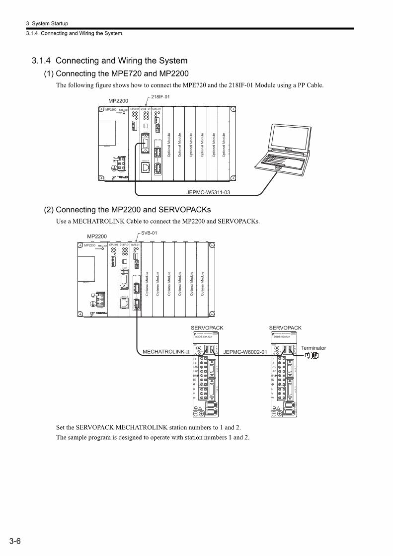
3.1.4 Connecting and Wiring the System(1) Connecting the MPE720 and MP2200
The following figure shows how to connect the MPE720 and the 218IF-01 Module using a PP Cable.
(2) Connecting the MP2200 and SERVOPACKsUse a MECHATROLINK Cable to connect the MP2200 and SERVOPACKs.
Set the SERVOPACK MECHATROLINK station numbers to 1 and 2.The sample program is designed to operate with station numbers 1 and 2.
JEPMC-W5311-03
MP2200 MBU-02 CPU-01 SVB-01218IF-01
CN1
CN2
BATTEY
POWER
DC
PORT
10Base-T
POWER
M- /
MP2200218IF-01
Opt
iona
l Mod
ule
Opt
iona
l Mod
ule
Opt
iona
l Mod
ule
Opt
iona
l Mod
ule
Opt
iona
l Mod
ule
Opt
iona
l Mod
ule
YASKAWA SERVOPACK 200V
SGDS-02A12A
SW1
CHARGE
CN3
A/B
CN1
CN2
CN4
L1L2
L2CL1C
B1/B2
U
VW
CN6
YASKAWA SERVOPACK 200V
SGDS-02A12A
SW1
CHARGE
CN3
A/B
CN1
CN2
CN4
L1L2
L2CL1C
B1/B2
U
VW
CN6MECHATROLINK-II
MP2200 MBU-02 CPU-01 SVB-01218IF-01
CN1
CN2
BATTEY
POWER
DC
PORT
10Base-T
POWER
M- /
MP2200SVB-01
JEPMC-W6002-01
SERVOPACK SERVOPACK
Opt
iona
l Mod
ule
Opt
iona
l Mod
ule
Opt
iona
l Mod
ule
Opt
iona
l Mod
ule
Opt
iona
l Mod
ule
Opt
iona
l Mod
ule
Terminator
3.1 Outline
3-7
3
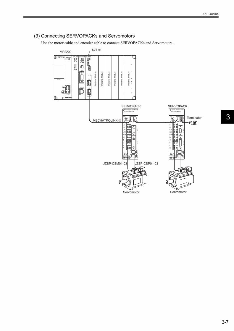
(3) Connecting SERVOPACKs and ServomotorsUse the motor cable and encoder cable to connect SERVOPACKs and Servomotors.
YASKAWA SERVOPACK 200V
SGDS-02A12A
SW1
CHARGE
CN3
A/B
CN1
CN2
CN4
L1L2
L2CL1C
B1/B2
U
VW
CN6
YASKAWA SERVOPACK 200V
SGDS-02A12A
SW1
CHARGE
CN3
A/B
CN1
CN2
CN4
L1L2
L2CL1C
B1/B2
U
VW
CN6MECHATROLINK-II
JZSP-CSP01-03JZSP-CSM01-03
MP2200 MBU-02 CPU-01 SVB-01218IF-01
CN1
CN2
BATTEY
POWER
DC
PORT
10Base-T
POWER
M- /
MP2200SVB-01
SERVOPACK SERVOPACK
Servomotor Servomotor
Opt
iona
l Mod
ule
Opt
iona
l Mod
ule
Opt
iona
l Mod
ule
Opt
iona
l Mod
ule
Opt
iona
l Mod
ule
Opt
iona
l Mod
ule
Terminator
3 System Startup
3.1.5 Initializing the System
3-8
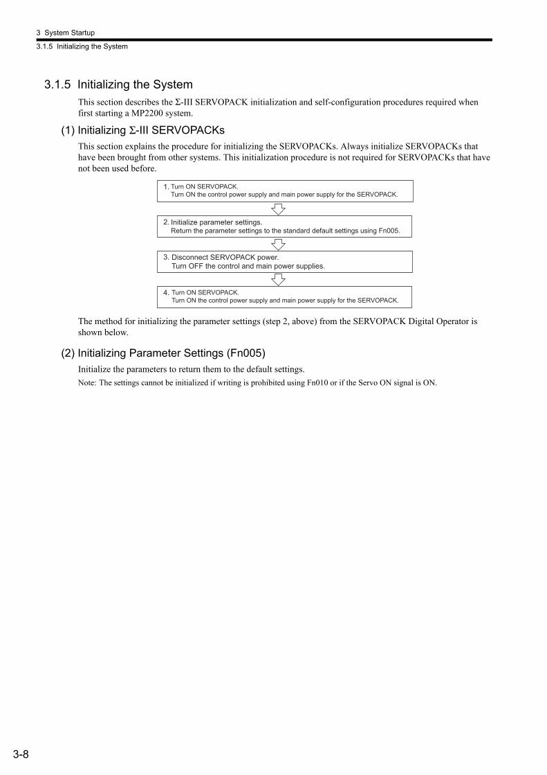
3.1.5 Initializing the SystemThis section describes the Σ-III SERVOPACK initialization and self-configuration procedures required when first starting a MP2200 system.
(1) Initializing Σ-III SERVOPACKsThis section explains the procedure for initializing the SERVOPACKs. Always initialize SERVOPACKs that have been brought from other systems. This initialization procedure is not required for SERVOPACKs that have not been used before.
The method for initializing the parameter settings (step 2, above) from the SERVOPACK Digital Operator is shown below.
(2) Initializing Parameter Settings (Fn005)Initialize the parameters to return them to the default settings.Note: The settings cannot be initialized if writing is prohibited using Fn010 or if the Servo ON signal is ON.
1.
2.
3.
4.
Turn ON SERVOPACK. Turn ON the control power supply and main power supply for the SERVOPACK.
Initialize parameter settings. Return the parameter settings to the standard default settings using Fn005.
Disconnect SERVOPACK power. Turn OFF the control and main power supplies.
Turn ON SERVOPACK. Turn ON the control power supply and main power supply for the SERVOPACK.
3.1 Outline
3-9
3
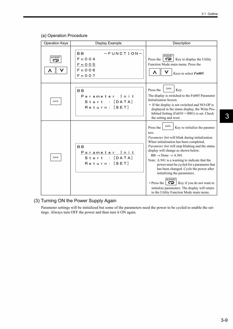
(a) Operation Procedure
(3) Turning ON the Power Supply AgainParameter settings will be initialized but some of the parameters need the power to be cycled to enable the set-tings. Always turn OFF the power and then turn it ON again.
Operation Keys Display Example Description
Press the Key to display the Utility Function Mode main menu. Press the
Keys to select Fn005.
Press the Key.The display is switched to the Fn005 Parameter Initialization Screen.• If the display is not switched and NO-OP is
displayed in the status display, the Write Pro-hibited Setting (Fn010 = 0001) is set. Check the setting and reset.
Press the Key to initialize the parame-ters.Parameter Init will blink during initialization. When initialization has been completed, Parameter Init will stop blinking and the status display will change as shown below.
BB → Done → A.941Note: A.941 is a warning to indicate that the
power must be cycled for a parameter that has been changed. Cycle the power after initializing the parameters.
• Press the Key if you do not want to initialize parameters. The display will return to the Utility Function Mode main menu.
3 System Startup
3.1.5 Initializing the System
3-10
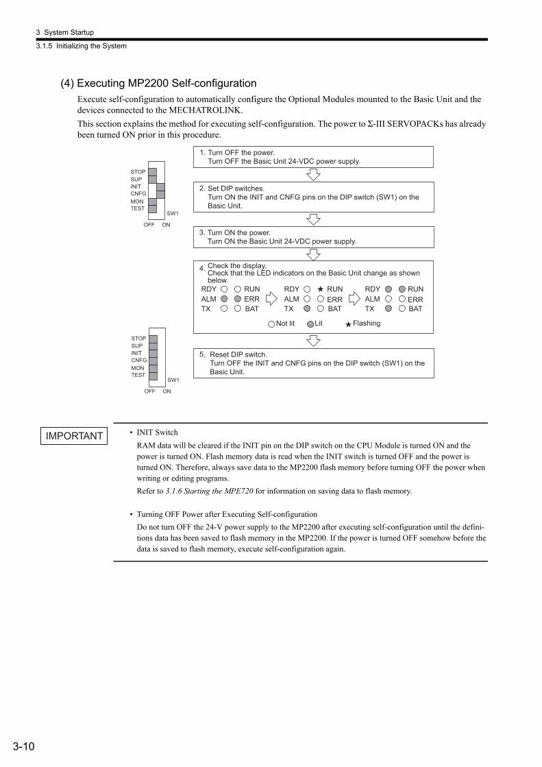
(4) Executing MP2200 Self-configurationExecute self-configuration to automatically configure the Optional Modules mounted to the Basic Unit and the devices connected to the MECHATROLINK.This section explains the method for executing self-configuration. The power to Σ-III SERVOPACKs has already been turned ON prior in this procedure.
• INIT SwitchRAM data will be cleared if the INIT pin on the DIP switch on the CPU Module is turned ON and the power is turned ON. Flash memory data is read when the INIT switch is turned OFF and the power is turned ON. Therefore, always save data to the MP2200 flash memory before turning OFF the power when writing or editing programs.Refer to 3.1.6 Starting the MPE720 for information on saving data to flash memory.
• Turning OFF Power after Executing Self-configurationDo not turn OFF the 24-V power supply to the MP2200 after executing self-configuration until the defini-tions data has been saved to flash memory in the MP2200. If the power is turned OFF somehow before the data is saved to flash memory, execute self-configuration again.
1.
2.
3.
4.
RDYALMTX BAT
RUNERR
RDYALMTX BAT
RUNERR
RDYALMTX BAT
RUNERR
5.
SW1
OFF
STOPSUPINITCNFGMONTEST
ON
SW1
OFF
STOPSUPINITCNFGMONTEST
ON
Turn OFF the power. Turn OFF the Basic Unit 24-VDC power supply.
Set DIP switches. Turn ON the INIT and CNFG pins on the DIP switch (SW1) on the Basic Unit.
Turn ON the power.Turn ON the Basic Unit 24-VDC power supply.
Check the display.Check that the LED indicators on the Basic Unit change as shown below.
Not lit Flashing Lit
Reset DIP switch.Turn OFF the INIT and CNFG pins on the DIP switch (SW1) on the Basic Unit.
IMPORTANT

3.1 Outline
3-11
3
3.1.6 Starting the MPE720This section describes the preparations for connecting the MPE720 to the MP2200, and the method for installing the sample program for the MP2200.
(1) MPE720 Startup ProcedureMake sure the MPE720 System Software is installed in advance. Refer to the Machine Controller MP900/MP2000 Series Programming Device Software MPE720 User’s Manual (Ref. No. SIEPC88070005) for informa-tion on installing the MPE720. The startup procedure is shown in the following flow-chart.
1.
2.
3.
4.
5.
6.
7.
8.
9.
10.
11.
Starting the MPE720 Start the MPE720.
Communication settings Define communications with the MP2200.
Creating group folders Create a group folder.
Creating an order folder Create an order folder.
Creating a controller folder Create a controller folder.
Logging on online Log on online to the MP2200.
Loading the sample programs Load the sample programs from the MPE720 system CD-ROM.
Transferring individual sample programs Transfer the sample programs individually.
Setting individual parameters Set the individual parameters to match the sample program.
Saving to flash memory Save the sample program to the MP2200 flash memory.
All program file dump Back up MP2200 data on the computer hard disk.
3 System Startup
3.1.6 Starting the MPE720
3-12
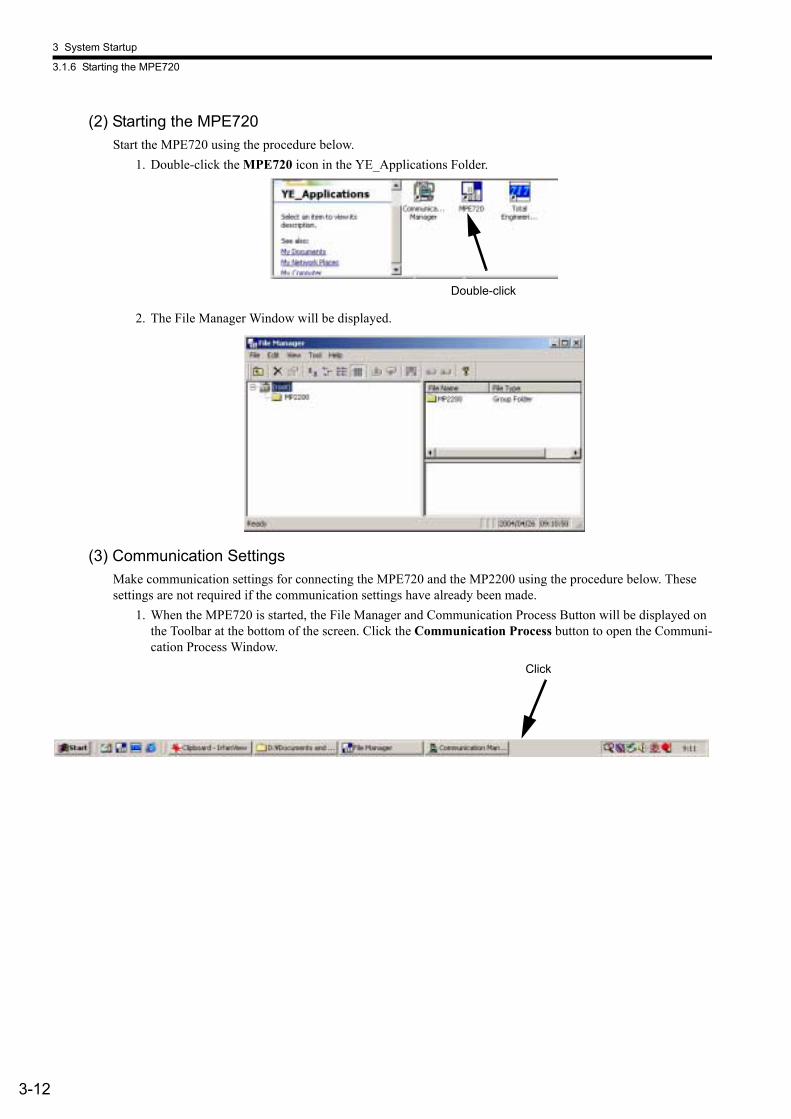
(2) Starting the MPE720Start the MPE720 using the procedure below.
1. Double-click the MPE720 icon in the YE_Applications Folder.
2. The File Manager Window will be displayed.
(3) Communication SettingsMake communication settings for connecting the MPE720 and the MP2200 using the procedure below. These settings are not required if the communication settings have already been made.
1. When the MPE720 is started, the File Manager and Communication Process Button will be displayed on the Toolbar at the bottom of the screen. Click the Communication Process button to open the Communi-cation Process Window.
Double-click
Click

3.1 Outline
3-13
3
2. Double-click Logical PT number 1 in the Communication Process Window to display the Logical Port Setting Window.
3. For RS-232C connections, select Port Kind - Serial in the Logical Port Setting Window.
4. Setting Serial Communication Portsa) Click the Detail button in the Logical Port Setting Window.
Double-click
3 System Startup
3.1.6 Starting the MPE720
3-14
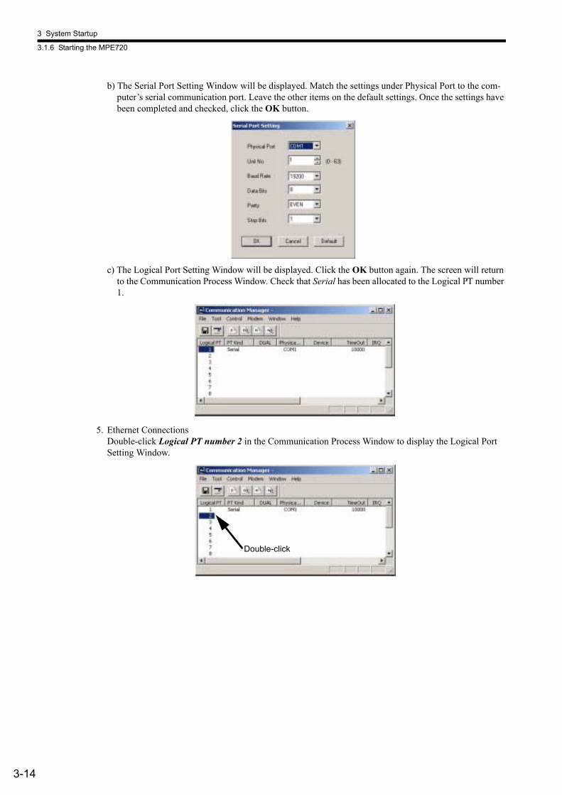
b) The Serial Port Setting Window will be displayed. Match the settings under Physical Port to the com-puter’s serial communication port. Leave the other items on the default settings. Once the settings have been completed and checked, click the OK button.
c) The Logical Port Setting Window will be displayed. Click the OK button again. The screen will return to the Communication Process Window. Check that Serial has been allocated to the Logical PT number 1.
5. Ethernet ConnectionsDouble-click Logical PT number 2 in the Communication Process Window to display the Logical Port Setting Window.
Double-click
3.1 Outline
3-15
3
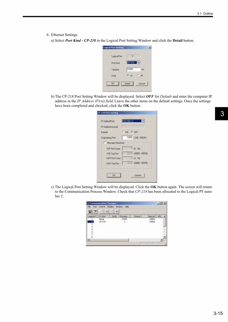
6. Ethernet Settingsa) Select Port Kind - CP-218 in the Logical Port Setting Window and click the Detail button.
b) The CP-218 Port Setting Window will be displayed. Select OFF for Default and enter the computer IP address in the IP Address (First) field. Leave the other items on the default settings. Once the settings have been completed and checked, click the OK button.
c) The Logical Port Setting Window will be displayed. Click the OK button again. The screen will return to the Communication Process Window. Check that CP-218 has been allocated to the Logical PT num-ber 2.
3 System Startup
3.1.6 Starting the MPE720
3-16
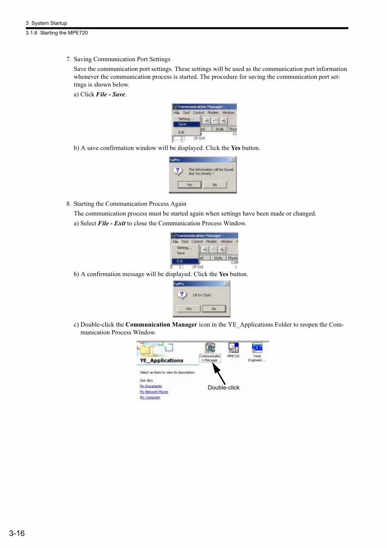
7. Saving Communication Port SettingsSave the communication port settings. These settings will be used as the communication port information whenever the communication process is started. The procedure for saving the communication port set-tings is shown below.a) Click File - Save.
b) A save confirmation window will be displayed. Click the Yes button.
8. Starting the Communication Process AgainThe communication process must be started again when settings have been made or changed.a) Select File - Exit to close the Communication Process Window.
b) A confirmation message will be displayed. Click the Yes button.
c) Double-click the Communication Manager icon in the YE_Applications Folder to reopen the Com-munication Process Window.
Double-click
3.1 Outline
3-17
3
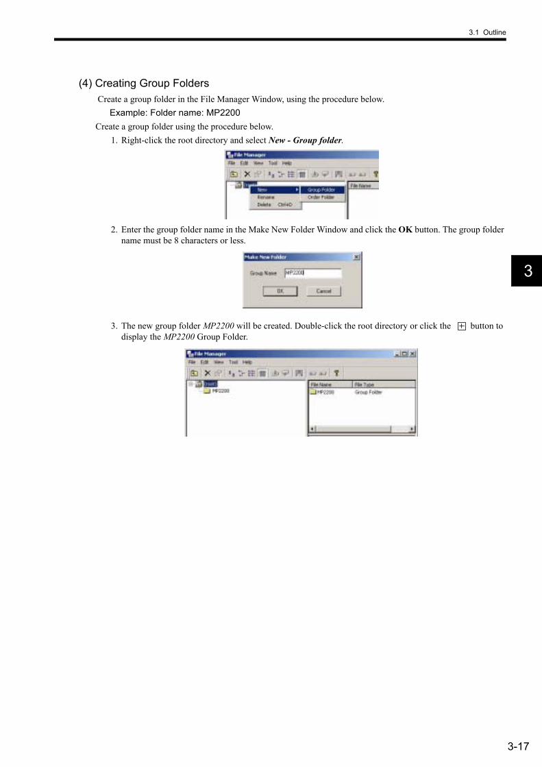
(4) Creating Group Folders Create a group folder in the File Manager Window, using the procedure below.
Example: Folder name: MP2200Create a group folder using the procedure below.
1. Right-click the root directory and select New - Group folder.
2. Enter the group folder name in the Make New Folder Window and click the OK button. The group folder name must be 8 characters or less.
3. The new group folder MP2200 will be created. Double-click the root directory or click the button to display the MP2200 Group Folder.
3 System Startup
3.1.6 Starting the MPE720
3-18
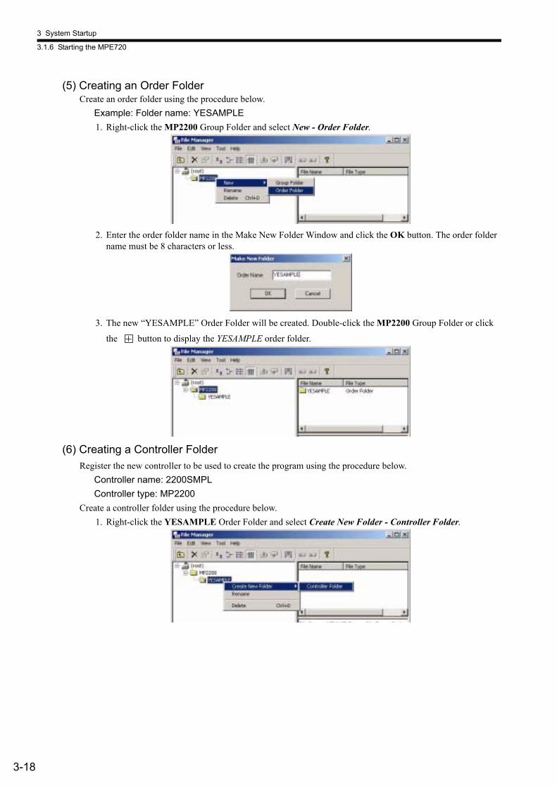
(5) Creating an Order FolderCreate an order folder using the procedure below.
Example: Folder name: YESAMPLE1. Right-click the MP2200 Group Folder and select New - Order Folder.
2. Enter the order folder name in the Make New Folder Window and click the OK button. The order folder name must be 8 characters or less.
3. The new “YESAMPLE” Order Folder will be created. Double-click the MP2200 Group Folder or click
the button to display the YESAMPLE order folder.
(6) Creating a Controller FolderRegister the new controller to be used to create the program using the procedure below.
Controller name: 2200SMPLController type: MP2200
Create a controller folder using the procedure below.1. Right-click the YESAMPLE Order Folder and select Create New Folder - Controller Folder.
3.1 Outline
3-19
3
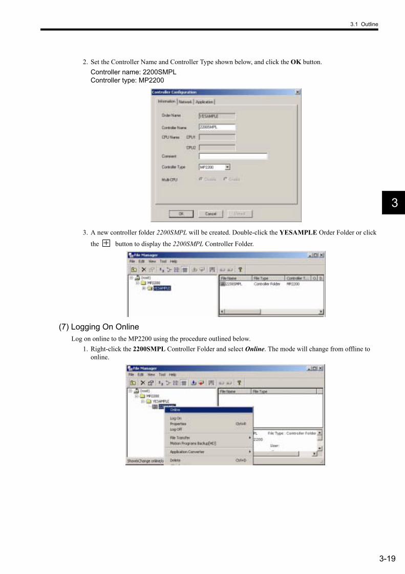
2. Set the Controller Name and Controller Type shown below, and click the OK button.Controller name: 2200SMPLController type: MP2200
3. A new controller folder 2200SMPL will be created. Double-click the YESAMPLE Order Folder or click
the button to display the 2200SMPL Controller Folder.
(7) Logging On OnlineLog on online to the MP2200 using the procedure outlined below.
1. Right-click the 2200SMPL Controller Folder and select Online. The mode will change from offline to online.
3 System Startup
3.1.6 Starting the MPE720
3-20
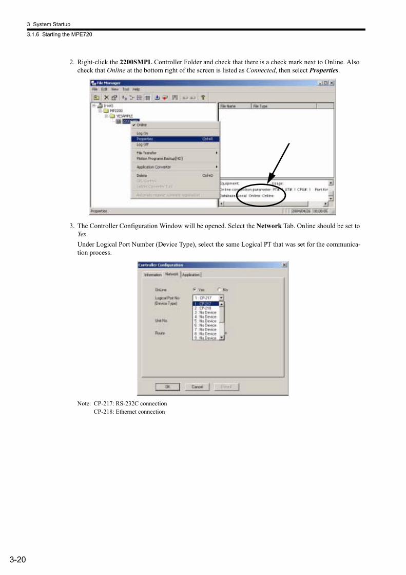
2. Right-click the 2200SMPL Controller Folder and check that there is a check mark next to Online. Also check that Online at the bottom right of the screen is listed as Connected, then select Properties.
3. The Controller Configuration Window will be opened. Select the Network Tab. Online should be set to Yes.Under Logical Port Number (Device Type), select the same Logical PT that was set for the communica-tion process.
Note: CP-217: RS-232C connectionCP-218: Ethernet connection

3.1 Outline
3-21
3
4. For RS-232C connections, leave all settings other than Logical Port Number (Device Type) on the default settings.
5. For Ethernet connections, make the settings shown below.
6. A confirmation message will be displayed. Click the Yes button.
3 System Startup
3.1.6 Starting the MPE720
3-22
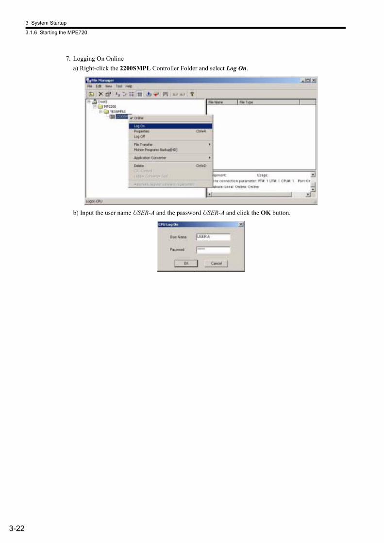
7. Logging On Onlinea) Right-click the 2200SMPL Controller Folder and select Log On.
b) Input the user name USER-A and the password USER-A and click the OK button.
3.1 Outline
3-23
3
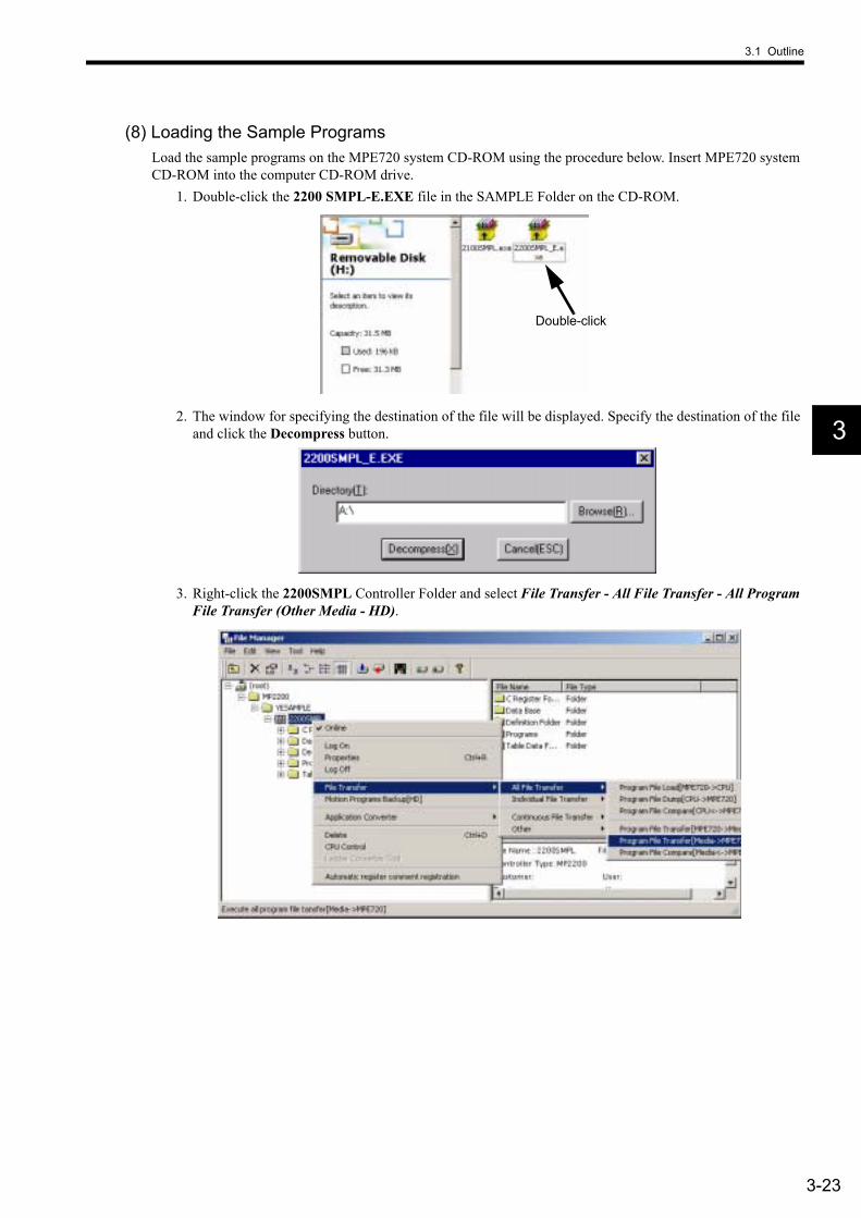
(8) Loading the Sample ProgramsLoad the sample programs on the MPE720 system CD-ROM using the procedure below. Insert MPE720 system CD-ROM into the computer CD-ROM drive.
1. Double-click the 2200 SMPL-E.EXE file in the SAMPLE Folder on the CD-ROM.
2. The window for specifying the destination of the file will be displayed. Specify the destination of the file and click the Decompress button.
3. Right-click the 2200SMPL Controller Folder and select File Transfer - All File Transfer - All Program File Transfer (Other Media - HD).
Double-click
3 System Startup
3.1.6 Starting the MPE720
3-24
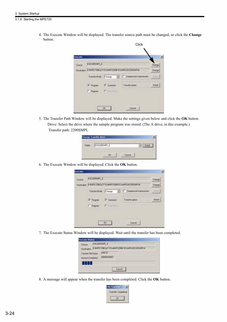
4. The Execute Window will be displayed. The transfer source path must be changed, so click the Change button.
5. The Transfer Path Window will be displayed. Make the settings given below and click the OK button.Drive: Select the drive where the sample program was stored. (The A drive, in this example.) Transfer path: 2200SMPL
6. The Execute Window will be displayed. Click the OK button.
7. The Execute Status Window will be displayed. Wait until the transfer has been completed.
8. A message will appear when the transfer has been completed. Click the OK button.
Click
3.1 Outline
3-25
3
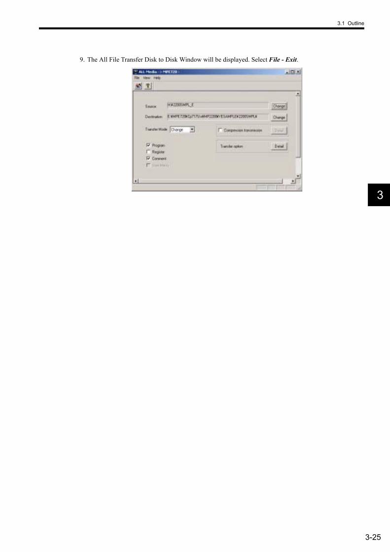
9. The All File Transfer Disk to Disk Window will be displayed. Select File - Exit.
3 System Startup
3.1.6 Starting the MPE720
3-26
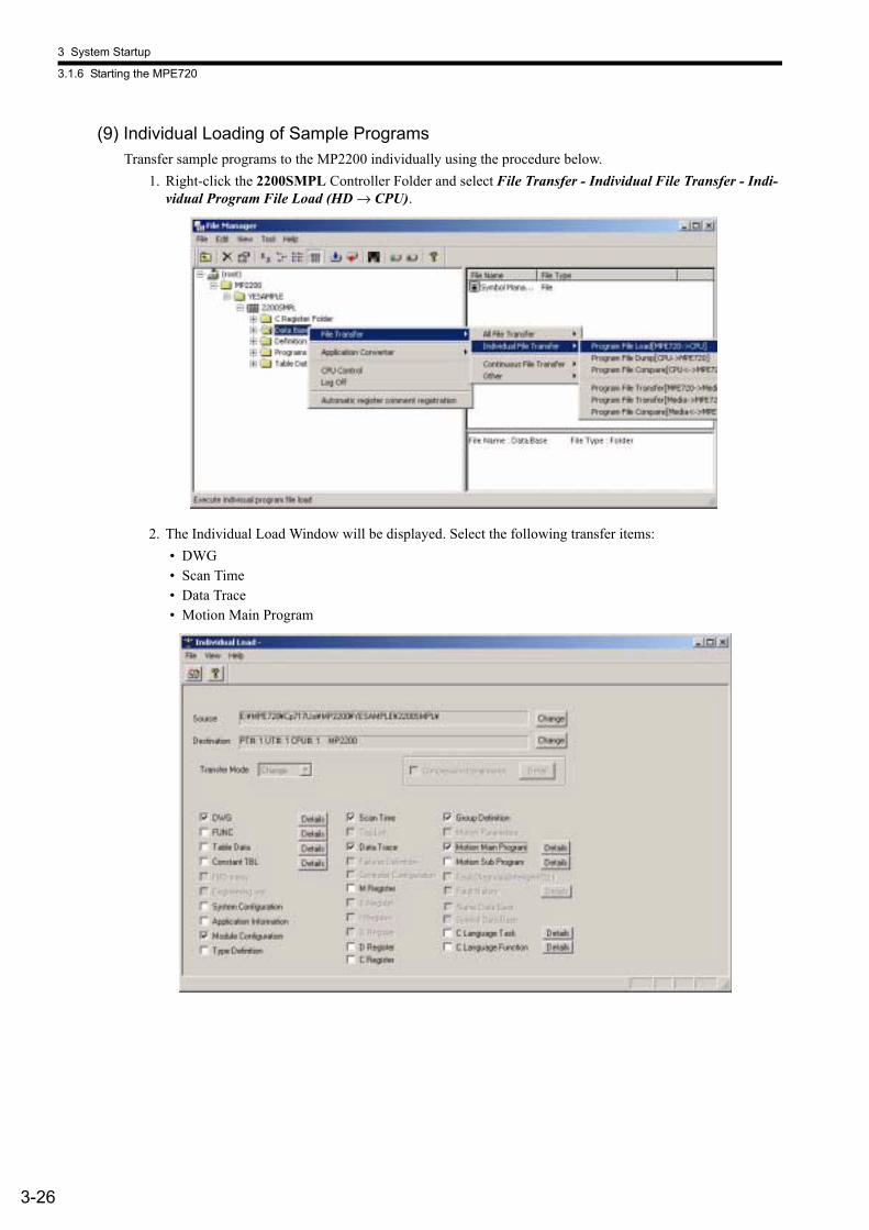
(9) Individual Loading of Sample ProgramsTransfer sample programs to the MP2200 individually using the procedure below.
1. Right-click the 2200SMPL Controller Folder and select File Transfer - Individual File Transfer - Indi-vidual Program File Load (HD → CPU).
2. The Individual Load Window will be displayed. Select the following transfer items: • DWG• Scan Time• Data Trace• Motion Main Program
3.1 Outline
3-27
3
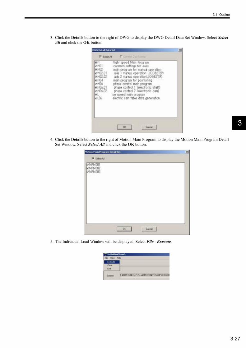
3. Click the Details button to the right of DWG to display the DWG Detail Data Set Window. Select Select All and click the OK button.
4. Click the Details button to the right of Motion Main Program to display the Motion Main Program Detail Set Window. Select Select All and click the OK button.
5. The Individual Load Window will be displayed. Select File - Execute.

3 System Startup
3.1.6 Starting the MPE720
3-28
6. A confirmation message will be displayed. Click the Yes button.
7. The Execute Status Window will be displayed. Wait until the transfer has been completed.
8. A message will appear when the transfer has been completed. Click the OK button.
9. The Individual Load Window will be displayed. Select File - Exit.
3.1 Outline
3-29
3
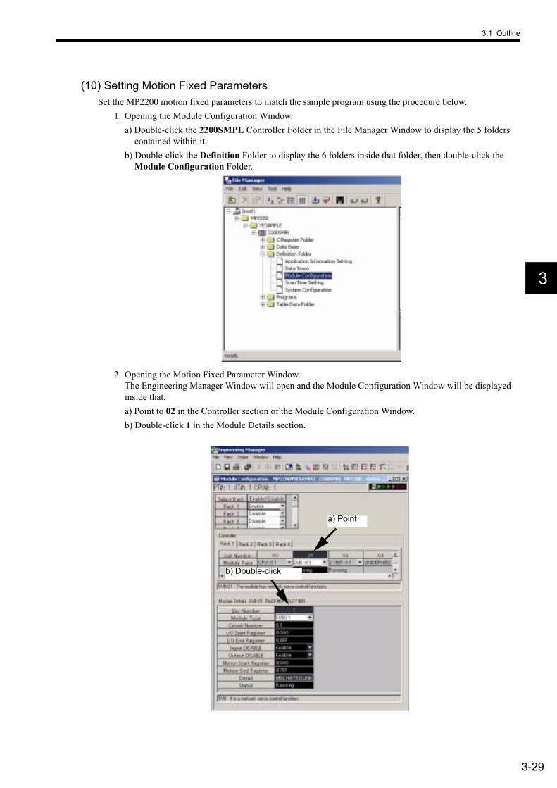
(10) Setting Motion Fixed ParametersSet the MP2200 motion fixed parameters to match the sample program using the procedure below.
1. Opening the Module Configuration Window.a) Double-click the 2200SMPL Controller Folder in the File Manager Window to display the 5 folders
contained within it. b) Double-click the Definition Folder to display the 6 folders inside that folder, then double-click the
Module Configuration Folder.
2. Opening the Motion Fixed Parameter Window. The Engineering Manager Window will open and the Module Configuration Window will be displayed inside that. a) Point to 02 in the Controller section of the Module Configuration Window. b) Double-click 1 in the Module Details section.
a) Point
b) Double-click
3 System Startup
3.1.6 Starting the MPE720
3-30
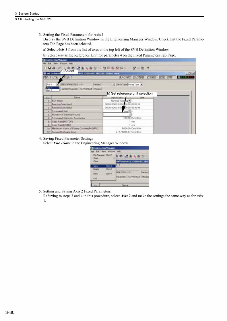
3. Setting the Fixed Parameters for Axis 1Display the SVB Definition Window in the Engineering Manager Window. Check that the Fixed Parame-ters Tab Page has been selected.a) Select Axis 1 from the list of axes at the top left of the SVB Definition Window. b) Select mm as the Reference Unit for parameter 4 on the Fixed Parameters Tab Page.
4. Saving Fixed Parameter SettingsSelect File - Save in the Engineering Manager Window.
5. Setting and Saving Axis 2 Fixed ParametersReferring to steps 3 and 4 in this procedure, select Axis 2 and make the settings the same way as for axis 1.
b) Set reference unit selection
a) Select
3.1 Outline
3-31
3
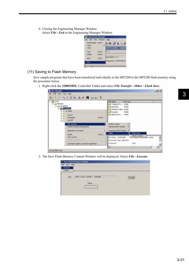
6. Closing the Engineering Manager Window Select File - Exit in the Engineering Manager Window.
(11) Saving to Flash MemorySave sample programs that have been transferred individually to the MP2200 to the MP2200 flash memory using the procedure below.
1. Right-click the 2200SMPL Controller Folder and select File Transfer - Other - Flash Save.
2. The Save Flash Memory Content Window will be displayed. Select File - Execute.
3 System Startup
3.1.6 Starting the MPE720
3-32
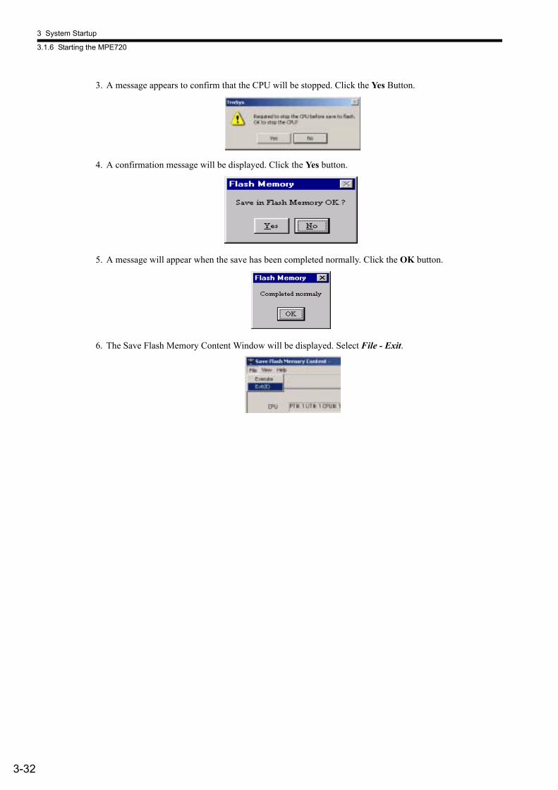
3. A message appears to confirm that the CPU will be stopped. Click the Yes Button.
4. A confirmation message will be displayed. Click the Yes button.
5. A message will appear when the save has been completed normally. Click the OK button.
6. The Save Flash Memory Content Window will be displayed. Select File - Exit.
3.1 Outline
3-33
3
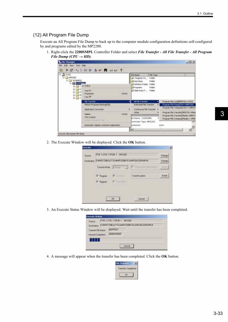
(12) All Program File DumpExecute an All Program File Dump to back up to the computer module configuration definitions self-configured by and programs edited by the MP2200.
1. Right-click the 2200SMPL Controller Folder and select File Transfer - All File Transfer - All Program File Dump (CPU → HD).
2. The Execute Window will be displayed. Click the OK button.
3. An Execute Status Window will be displayed. Wait until the transfer has been completed.
4. A message will appear when the transfer has been completed. Click the OK button.
3 System Startup
3.1.6 Starting the MPE720
3-34
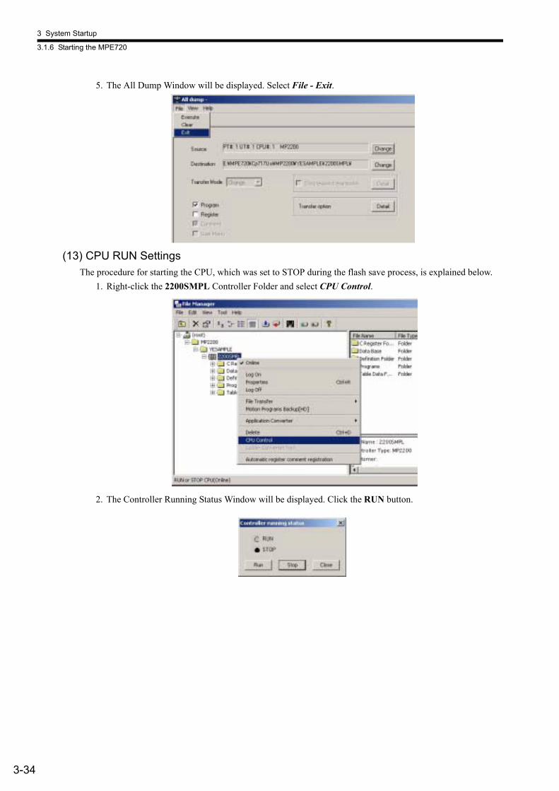
5. The All Dump Window will be displayed. Select File - Exit.
(13) CPU RUN SettingsThe procedure for starting the CPU, which was set to STOP during the flash save process, is explained below.
1. Right-click the 2200SMPL Controller Folder and select CPU Control.
2. The Controller Running Status Window will be displayed. Click the RUN button.

3.1 Outline
3-35
3
3. A confirmation message will be displayed. Click the Yes button. Check that the RUN LED indicator on the CPU Module is lit.
4. The Controller Running Status Window will be displayed again. Click the Close button.
(14) Logging OffLog off when you have finished with the MPE720 using the procedure below.
1. Right-click the 2200SMPL Controller Folder and select Log Off.
2. A confirmation message will be displayed. Click the Yes button.

3 System Startup
3.2.1 Description
3-36
3.2 Sample Program 1: Manual Operation3.2.1 Description
(1) Program Outline• The H01 drawing (ladder program) turns ON the servo, resets alarms, and sets parameters. • The H02.01 drawing (ladder program) controls jog and step operation for axis 1.• The H02.02 drawing (ladder program) controls jog and step operation for axis 2.• Refer to 3.2.3 Program Details for details on the sample program.
This sample program has no power OFF circuit for the SERVOPACK in the event of emergency stops or overtravel. Include a proper emergency stop circuit in actual applications.
END
SEEName H02.02
END
SEEName H01
END
SEEName H02
END
END
SEEName H02.01
H01 Drawing
Grandchild Drawings
• SERVO ON • Alarm reset
• Parameter settings
H02 Drawing
Child Drawings Parent Drawings
H Drawing
High-speed scan
H02.01 Drawing
H02.02 Drawing
Axis 2
• Jog operation Axis 1
• Step operation
• Jog operation • Step operation
IMPORTANT

3.2 Sample Program 1: Manual Operation
3-37
3
3.2.2 Operation(1) Display of Tuning Panel Window
In this sample program, run, stop, and other operations can be checked from a Tuning Panel Window. Use the following procedure to display the Tuning Panel Window.
1. Log on online and open the 2200SMPL Controller Folder, then the Programs and High Scan Programs folders in the MPE720 File Manager Window.
2. Right-click the H02 drawing in the High Scan Programs Folder and select Open - Tuning Panel.
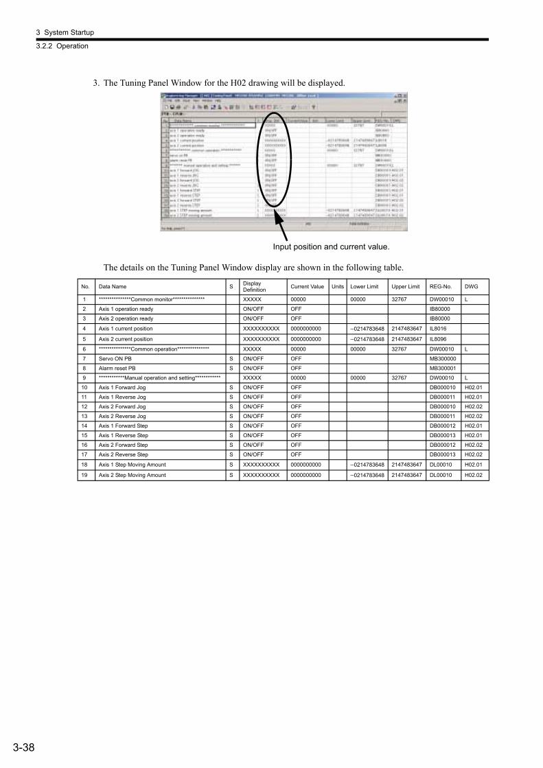
3 System Startup
3.2.2 Operation
3-38
3. The Tuning Panel Window for the H02 drawing will be displayed.
The details on the Tuning Panel Window display are shown in the following table.
No. Data Name S Display Definition Current Value Units Lower Limit Upper Limit REG-No. DWG
1 ***************Common monitor*************** XXXXX 00000 00000 32767 DW00010 L
2 Axis 1 operation ready ON/OFF OFF IB80000
3 Axis 2 operation ready ON/OFF OFF IB80000
4 Axis 1 current position XXXXXXXXXX 0000000000 −0214783648 2147483647 IL8016
5 Axis 2 current position XXXXXXXXXX 0000000000 −0214783648 2147483647 IL8096
6 ***************Common operation*************** XXXXX 00000 00000 32767 DW00010 L
7 Servo ON PB S ON/OFF OFF MB300000
8 Alarm reset PB S ON/OFF OFF MB300001
9 ************Manual operation and setting************ XXXXX 00000 00000 32767 DW00010 L
10 Axis 1 Forward Jog S ON/OFF OFF DB000010 H02.01
11 Axis 1 Reverse Jog S ON/OFF OFF DB000011 H02.01
12 Axis 2 Forward Jog S ON/OFF OFF DB000010 H02.02
13 Axis 2 Reverse Jog S ON/OFF OFF DB000011 H02.02
14 Axis 1 Forward Step S ON/OFF OFF DB000012 H02.01
15 Axis 1 Reverse Step S ON/OFF OFF DB000013 H02.01
16 Axis 2 Forward Step S ON/OFF OFF DB000012 H02.02
17 Axis 2 Reverse Step S ON/OFF OFF DB000013 H02.02
18 Axis 1 Step Moving Amount S XXXXXXXXXX 0000000000 −0214783648 2147483647 DL00010 H02.01
19 Axis 2 Step Moving Amount S XXXXXXXXXX 0000000000 −0214783648 2147483647 DL00010 H02.02
Input position and current value.
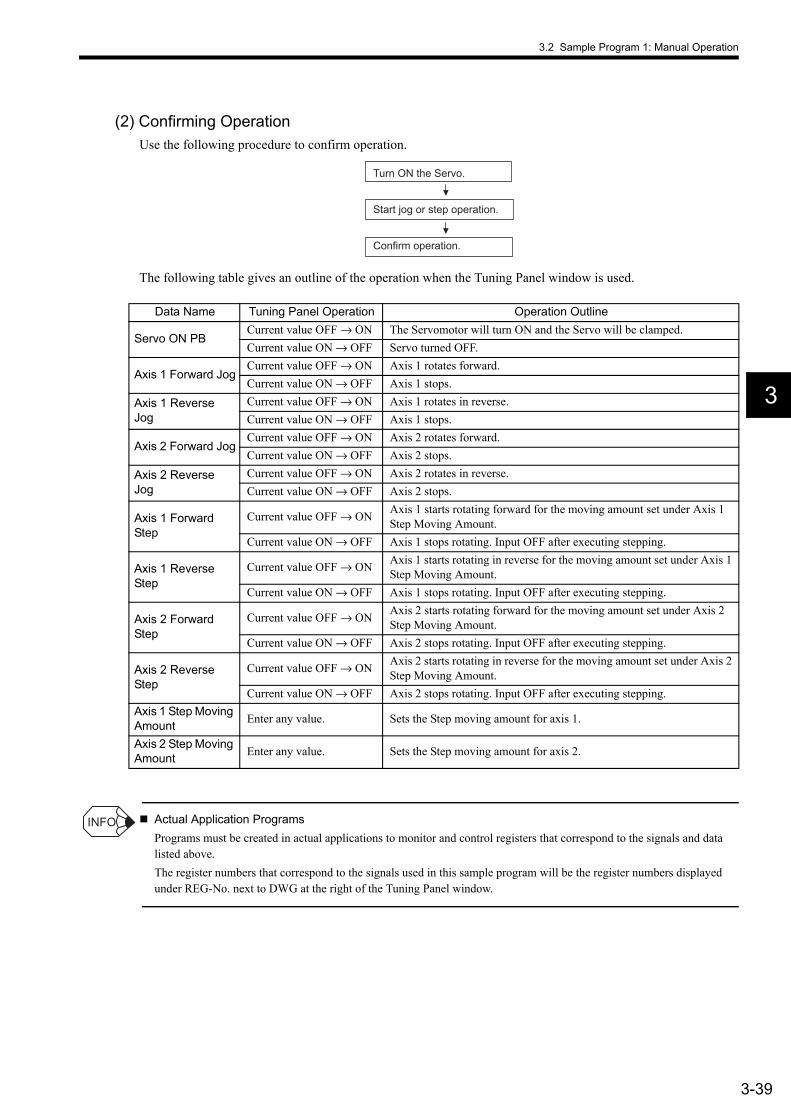
3.2 Sample Program 1: Manual Operation
3-39
3
(2) Confirming OperationUse the following procedure to confirm operation.
The following table gives an outline of the operation when the Tuning Panel window is used.
Actual Application ProgramsPrograms must be created in actual applications to monitor and control registers that correspond to the signals and data listed above.The register numbers that correspond to the signals used in this sample program will be the register numbers displayed under REG-No. next to DWG at the right of the Tuning Panel window.
Turn ON the Servo.
Confirm operation.
Start jog or step operation.
Data Name Tuning Panel Operation Operation Outline
Servo ON PBCurrent value OFF → ON The Servomotor will turn ON and the Servo will be clamped.Current value ON → OFF Servo turned OFF.
Axis 1 Forward JogCurrent value OFF → ON Axis 1 rotates forward.Current value ON → OFF Axis 1 stops.
Axis 1 Reverse Jog
Current value OFF → ON Axis 1 rotates in reverse.Current value ON → OFF Axis 1 stops.
Axis 2 Forward JogCurrent value OFF → ON Axis 2 rotates forward.Current value ON → OFF Axis 2 stops.
Axis 2 Reverse Jog
Current value OFF → ON Axis 2 rotates in reverse.Current value ON → OFF Axis 2 stops.
Axis 1 Forward Step
Current value OFF → ON Axis 1 starts rotating forward for the moving amount set under Axis 1 Step Moving Amount.
Current value ON → OFF Axis 1 stops rotating. Input OFF after executing stepping.
Axis 1 Reverse Step
Current value OFF → ON Axis 1 starts rotating in reverse for the moving amount set under Axis 1 Step Moving Amount.
Current value ON → OFF Axis 1 stops rotating. Input OFF after executing stepping.
Axis 2 Forward Step
Current value OFF → ON Axis 2 starts rotating forward for the moving amount set under Axis 2 Step Moving Amount.
Current value ON → OFF Axis 2 stops rotating. Input OFF after executing stepping.
Axis 2 Reverse Step
Current value OFF → ON Axis 2 starts rotating in reverse for the moving amount set under Axis 2 Step Moving Amount.
Current value ON → OFF Axis 2 stops rotating. Input OFF after executing stepping.Axis 1 Step Moving Amount Enter any value. Sets the Step moving amount for axis 1.
Axis 2 Step Moving Amount Enter any value. Sets the Step moving amount for axis 2.
INFO

3 System Startup
3.2.3 Program Details
3-40
3.2.3 Program Details(1) H Drawing
The H parent drawing controls the overall sample program.
########## Phase control ##########
########## Positioning operation ##########
########## Jog and step operation ##########
########## Servo ON and alarm reset ##########
Main Program High-speed Main Progra
########## High-speed main program ##########
Servo ON and alarm reset
Jog and step operation
Positioning operation
Electronic cam
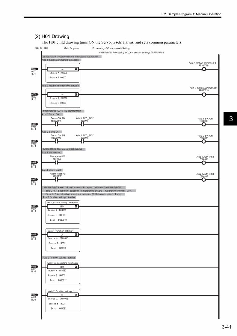
3.2 Sample Program 1: Manual Operation
3-41
3
(2) H01 DrawingThe H01 child drawing turns ON the Servo, resets alarms, and sets common parameters.
Axis 1 Servo ON ########## Servo ON ##########
Axis 2 function setting 1 (units)
Bits 4 to 7: Acceleration speed unit selection (0: Reference unit/s2 ; 1: ms) Bits 0 to 3: Speed unit selection (0: Reference unit/s2 ; 1: Reference unit/min2 ; 2: %
########## Speed unit and acceleration speed unit selection ##########
Axis 1 function setting 1 (units)
Axis 2 Servo ON
Axis 2 alarm reset
Axis 1 alarm reset ########## Alarm reset ##########
Axis 2 motion command 0 detection
Axis 1 motion command 0 detection ########## Motion command detection ##########
Main Program Processing of Common Axis Setting
########## Processing of common axis settings ##########
Axis 1 motion command 0
Axis 2 motion command 0
Axis 1, function setting 1 workpiece
Alarm reset PB
Servo ON PB Axis 1 SV_ON Axis 1 SVC_RDY
Servo ON PB Axis 2 SV_ON Axis 2 SVC_RDY
Alarm reset PB
Axis 1 ALM_RST
Axis 2 ALM_RST
Axis 1, function setting 1
Axis 2, function setting 1 workpiece
Axis 2, function setting 1
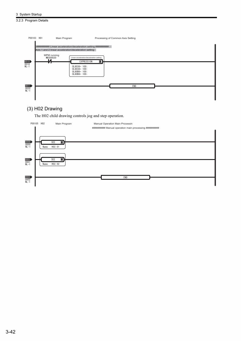
3 System Startup
3.2.3 Program Details
3-42
(3) H02 DrawingThe H02 child drawing controls jog and step operation.
MPM running Linear acceleration/deceleration setting
Axis 1 and 2 linear acceleration/deceleration setting ########## Linear acceleration/deceleration setting ##########
Main Program Processing of Common Axis Setting
Main Program Manual Operation Main Processin
########## Manual operation main processing ##########
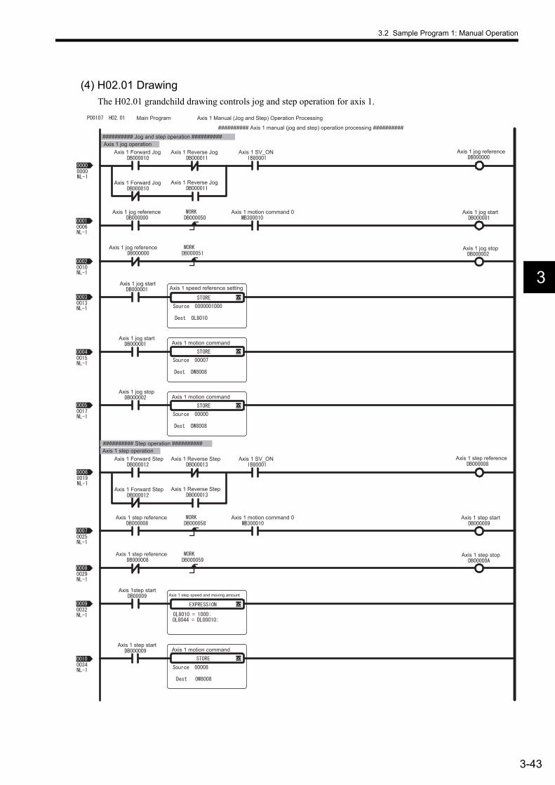
3.2 Sample Program 1: Manual Operation
3-43
3
(4) H02.01 DrawingThe H02.01 grandchild drawing controls jog and step operation for axis 1.
Axis 1 jog operation ########## Jog and step operation ##########
Main Program Axis 1 Manual (Jog and Step) Operation Processing
########## Axis 1 manual (jog and step) operation processing ##########
Axis 1 Forward Jog
Axis 1 speed reference setting
Axis 1 SV_ON
Axis 1 jog start
Axis 1 jog stop
Axis 1 jog start
Axis 1 motion command
Axis 1 motion command Axis 1 jog stop
Axis 1 jog reference
Axis 1 jog reference Axis 1 motion command 0
Axis 1 jog reference
Axis 1 jog start
Axis 1 Forward Jog
Axis 1 Reverse Jog
Axis 1 Reverse Jog
Axis 1 step operation ########## Step operation ##########
Axis 1 Forward Step
Axis 1 step speed and moving amount
Axis 1 SV_ON
Axis 1 step start
Axis 1 step stop
Axis 1step start
Axis 1 motion command
Axis 1 step reference
Axis 1 step reference Axis 1 motion command 0
Axis 1 step reference
Axis 1 step start
Axis 1 Forward Step
Axis 1 Reverse Step
Axis 1 Reverse Step

3 System Startup
3.2.3 Program Details
3-44
########## Reverse rotation selection ##########
Main Program Axis 1 Manual (Jog and Step) Operation Processing
Axis 1 motion command Axis 1 step stop
Axis 1 jog reference Axis 1 Reverse Axis 1 Reverse Jog
Axis 1 step reference
Axis 1 Reverse Step

3.2 Sample Program 1: Manual Operation
3-45
3
(5) H02.02 DrawingThe H02.02 grandchild drawing controls jog and step operation for axis 2.
Axis 2 jog operation ########## Jog and step operation ##########
Main Program Axis 2 Manual (Jog and Step) Operation Processing
########## Axis 2 manual (jog and step) operation processing ##########
Axis 2 Forward Jog
Axis 2 speed reference setting
Axis 2 SV_ON
Axis 2 jog start
Axis 2 jog stop
Axis 2 jog start
Axis 2 motion command
Axis 2 motion command Axis 2 jog stop
Axis 2 jog reference
Axis 2 jog reference Axis 2 motion command 0
Axis 2 jog reference
Axis 2 jog start
Axis 2 Forward Jog
Axis 2 Reverse Jog
Axis 2 Reverse Jog
Axis 2 step operation ########## Step operation ##########
Axis 2 Forward Step
Axis 2 step speed and moving amount
Axis 2 SV_ON
Axis 2 step start
Axis 2 step stop
Axis 2 step start
Axis 2 motion command
Axis 2 step reference
Axis 2 step reference
Axis 2 step reference
Axis 2 step start
Axis 2 Forward Step
Axis 2 Reverse Step
Axis 2 Reverse Step

3 System Startup
3.2.3 Program Details
3-46
########## Reverse rotation selection ##########
Main Program Axis 2 Manual (Jog and Step) Operation Processing
Axis 2 motion command Axis 2 step stop
Axis 2 jog reference Axis 2 Reverse Axis 2 Reverse Jog
Axis 2 step reference
Axis 2 Reverse Step
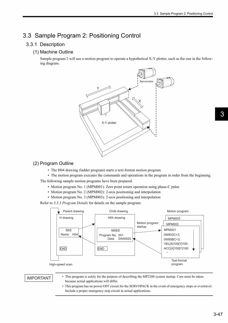
3.3 Sample Program 2: Positioning Control
3-47
3
3.3 Sample Program 2: Positioning Control3.3.1 Description
(1) Machine OutlineSample program 2 will use a motion program to operate a hypothetical X-Y plotter, such as the one in the follow-ing diagram.
(2) Program Outline• The H04 drawing (ladder program) starts a text-format motion program.• The motion program executes the commands and operations in the program in order from the beginning.
The following sample motion programs have been prepared.• Motion program No. 1 (MPM001): Zero point return operation using phase-C pulse• Motion program No. 2 (MPM002): 2-axis positioning and interpolation• Motion program No. 3 (MPM003): 2-axis positioning and interpolation
Refer to 3.3.3 Program Details for details on the sample program.
• This program is solely for the purpose of describing the MP2200 system startup. Care must be taken because actual applications will differ.
• This program has no power OFF circuit for the SERVOPACK in the event of emergency stops or overtravel. Include a proper emergency stop circuit in actual applications.
X
Y
Servomotor
X-Y plotter
SEE
ENDEND
MPM002
MPM003
MPM0010W803C=3;
VEL[X]100[Y]100;0W80BC=3;
ACC[X]100[Y]100;
MSEEProgram No. 001
Data DA00020Name H04
Parent drawing
H drawing H04 drawing
High-speed scan Text-format program
Child drawing Motion program
Motion program startup
IMPORTANT
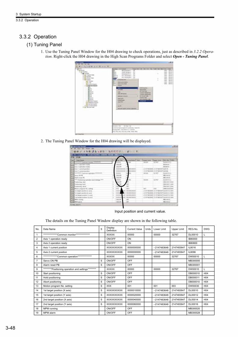
3 System Startup
3.3.2 Operation
3-48
3.3.2 Operation(1) Tuning Panel
1. Use the Tuning Panel Window for the H04 drawing to check operations, just as described in 3.2.2 Opera-tion. Right-click the H04 drawing in the High Scan Programs Folder and select Open - Tuning Panel.
2. The Tuning Panel Window for the H04 drawing will be displayed.
The details on the Tuning Panel Window display are shown in the following table.
No. Data Name S Display Definition Current Value Units Lower Limit Upper Limit REG-No. DWG
1 ***************Common monitor*************** XXXXX 00000 00000 32767 DL00010 L
2 Axis 1 operation ready ON/OFF ON IB80000
3 Axis 2 operation ready ON/OFF ON IB80800
4 Axis 1 current position XXXXXXXXXX 0000000000 −2147483648 2147483647 IL8016
5 Axis 2 current position XXXXXXXXXX 0000000000 −2147483648 2147483647 IL8096
6 ***************Common operation*************** XXXXX 00000 00000 32767 DW00010 L
7 Servo ON PB S ON/OFF OFF MB300000
8 Alarm reset PB S ON/OFF OFF MB300001
9 *********Positioning operation and settings********* XXXXX 00000 00000 32767 DW00010 L
10 Start positioning S ON/OFF OFF DB000010 H04
11 Hold positioning S ON/OFF OFF DB000011 H04
12 Abort positioning S ON/OFF OFF DB000010 H04
13 Motion program No. setting S XXX 001 001 003 DW00030 H04
14 1st target position (X axis) S XXXXXXXXXX 0000010000 −2147483648 2147483647 DL00010 H04
15 1st target position (Y axis) S XXXXXXXXXX 0000020000 −2147483648 2147483647 DL00012 H04
16 2nd target position (X axis) S XXXXXXXXXX 0000040000 −2147483648 2147483647 DL00014 H04
17 2nd target position (Y axis) S XXXXXXXXXX 0000060000 −2147483648 2147483647 DL00016 H04
18 MPM running ON/OFF OFF MB300020
19 MPM alarm ON/OFF OFF MB300028
Input position and current value.
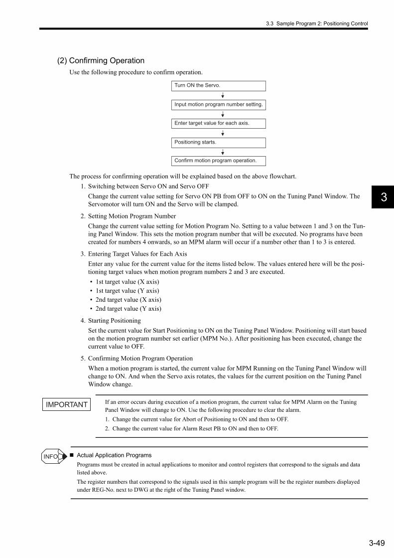
3.3 Sample Program 2: Positioning Control
3-49
3
(2) Confirming OperationUse the following procedure to confirm operation.
The process for confirming operation will be explained based on the above flowchart.1. Switching between Servo ON and Servo OFF
Change the current value setting for Servo ON PB from OFF to ON on the Tuning Panel Window. The Servomotor will turn ON and the Servo will be clamped.
2. Setting Motion Program NumberChange the current value setting for Motion Program No. Setting to a value between 1 and 3 on the Tun-ing Panel Window. This sets the motion program number that will be executed. No programs have been created for numbers 4 onwards, so an MPM alarm will occur if a number other than 1 to 3 is entered.
3. Entering Target Values for Each AxisEnter any value for the current value for the items listed below. The values entered here will be the posi-tioning target values when motion program numbers 2 and 3 are executed.• 1st target value (X axis)• 1st target value (Y axis)• 2nd target value (X axis)• 2nd target value (Y axis)
4. Starting PositioningSet the current value for Start Positioning to ON on the Tuning Panel Window. Positioning will start based on the motion program number set earlier (MPM No.). After positioning has been executed, change the current value to OFF.
5. Confirming Motion Program OperationWhen a motion program is started, the current value for MPM Running on the Tuning Panel Window will change to ON. And when the Servo axis rotates, the values for the current position on the Tuning Panel Window change.
If an error occurs during execution of a motion program, the current value for MPM Alarm on the Tuning Panel Window will change to ON. Use the following procedure to clear the alarm.1. Change the current value for Abort of Positioning to ON and then to OFF.2. Change the current value for Alarm Reset PB to ON and then to OFF.
Actual Application ProgramsPrograms must be created in actual applications to monitor and control registers that correspond to the signals and data listed above.The register numbers that correspond to the signals used in this sample program will be the register numbers displayed under REG-No. next to DWG at the right of the Tuning Panel window.
Turn ON the Servo.
Input motion program number setting.
Enter target value for each axis.
Positioning starts.
Confirm motion program operation.
IMPORTANT
INFO

3 System Startup
3.3.3 Program Details
3-50
3.3.3 Program Details(1) H04 drawing
The H04 child drawing manages and controls motion programs (MPM programs).
Main Program Positioning Operation Main Processing
########## Positioning operation main processing ##########
########## Main program startup sequence ##########Operation start
Hold request
Reset request
MPM number
MPM***execution
Start request
Holding
Axis 1 motion command 0 Axis 2 motion command 0
Operation reset
Travel data setting
MPM running
MPM alarm
Alarm reset PB Alarm reset request
MPM interpolation override
MPM running
MPM alarm
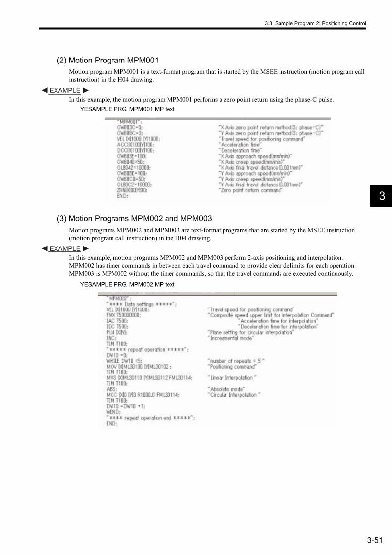
3.3 Sample Program 2: Positioning Control
3-51
3
(2) Motion Program MPM001Motion program MPM001 is a text-format program that is started by the MSEE instruction (motion program call instruction) in the H04 drawing.
In this example, the motion program MPM001 performs a zero point return using the phase-C pulse.YESAMPLE PRG. MPM001 MP text
(3) Motion Programs MPM002 and MPM003Motion programs MPM002 and MPM003 are text-format programs that are started by the MSEE instruction (motion program call instruction) in the H04 drawing.
In this example, motion programs MPM002 and MPM003 perform 2-axis positioning and interpolation. MPM002 has timer commands in between each travel command to provide clear delimits for each operation. MPM003 is MPM002 without the timer commands, so that the travel commands are executed continuously.
YESAMPLE PRG. MPM002 MP text
EXAMPLE
EXAMPLE
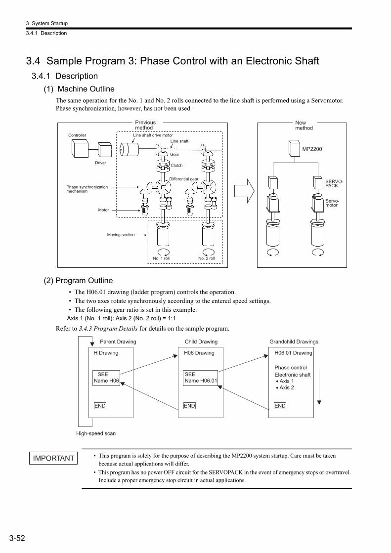
3 System Startup
3.4.1 Description
3-52
3.4 Sample Program 3: Phase Control with an Electronic Shaft3.4.1 Description
(1) Machine OutlineThe same operation for the No. 1 and No. 2 rolls connected to the line shaft is performed using a Servomotor. Phase synchronization, however, has not been used.
(2) Program Outline• The H06.01 drawing (ladder program) controls the operation.• The two axes rotate synchronously according to the entered speed settings.• The following gear ratio is set in this example.
Axis 1 (No. 1 roll): Axis 2 (No. 2 roll) = 1:1
Refer to 3.4.3 Program Details for details on the sample program.
• This program is solely for the purpose of describing the MP2200 system startup. Care must be taken because actual applications will differ.
• This program has no power OFF circuit for the SERVOPACK in the event of emergency stops or overtravel. Include a proper emergency stop circuit in actual applications.
MP2200
Servo-motor
SERVO- PACK
No. 1 roll
Controller
Driver
Phase synchronization mechanism
Motor
Gear
Differential gear
Clutch
Moving section
Line shaft Line shaft drive motor
No. 2 roll
New method
Previous method
SEEName H06
END END
SEEName H06.01
END
Parent Drawing
H Drawing
High-speed scan
H06 Drawing
Child Drawing
H06.01 Drawing
Grandchild Drawings
Phase control Electronic shaft • Axis 1 • Axis 2
IMPORTANT

3.4 Sample Program 3: Phase Control with an Electronic Shaft
3-53
3
3.4.2 Operation(1) Tuning Panel
1. Use the Tuning Panel Window for the H06 drawing to check operations, just as described in 3.2.2 Opera-tion. Right-click the H06 drawing in the High Scan Programs Folder and select Open - Tuning Panel.
2. The Tuning Panel Window for the H06 drawing will be displayed.
The details on the Tuning Panel Window display are shown in the following table.
Input position and current value.
No. Data Name S Display Definition
Current Value Units Lower Limit Upper Limit REG-No. DWG
1 ***************Common monitor*************** XXXXX 00000 00000 32767 DW00010 L
2 Axis 1 operation ready ON/OFF ON IB80000
3 Axis 2 operation ready ON/OFF ON IB80800
4 Axis 1 current position XXXXXXXXXX 0000000000 −2147483648 2147483647 IL8016
5 Axis 2 current position XXXXXXXXXX 0000000000 −2147483648 2147483647 IL8096
6 ***************Common operation*************** XXXXX 00000 00000 32767 DW00010 L
7 Servo ON PB S ON/OFF OFF MB300000
8 Alarm reset PB S ON/OFF OFF MB300001
9 *************Phase control (Electronic shaft)************* XXXXX 00000 00000 32767 DW00010 L
10 Electronic shaft start S ON/OFF OFF DB000010 H06.01
11 Speed setting (motor rated speed: 30000 mm/min) S XXXXXX 000000 mm/min −030000 030000 DL00010 H06.02
12 *************Phase control (Electronic cam)************* XXXXX 0000 0000 32767 DW00010 L
13 Electronic cam start S ON/OFF OFF DB000010 H06.02
14 Main axis speed setting (motor rated speed: 30000 mm/min) S XXXXXX 00000 mm/min 00000 030000 DL00010 H06.01
15 Cam axis: amplitude setting (double amplitude) S XXX.XXX 010.000 mm 000.000 999.999 ML30200
16 Cam axis: main axis moving amount per cycle S XXXXX.XXX 00500.000 mm 00000.000 50000.000 ML30202
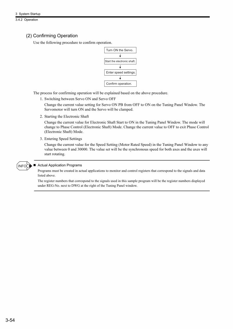
3 System Startup
3.4.2 Operation
3-54
(2) Confirming OperationUse the following procedure to confirm operation.
The process for confirming operation will be explained based on the above procedure.1. Switching between Servo ON and Servo OFF
Change the current value setting for Servo ON PB from OFF to ON on the Tuning Panel Window. The Servomotor will turn ON and the Servo will be clamped.
2. Starting the Electronic ShaftChange the current value for Electronic Shaft Start to ON in the Tuning Panel Window. The mode will change to Phase Control (Electronic Shaft) Mode. Change the current value to OFF to exit Phase Control (Electronic Shaft) Mode.
3. Entering Speed SettingsChange the current value for the Speed Setting (Motor Rated Speed) in the Tuning Panel Window to any value between 0 and 30000. The value set will be the synchronous speed for both axes and the axes will start rotating.
Actual Application ProgramsPrograms must be created in actual applications to monitor and control registers that correspond to the signals and data listed above.The register numbers that correspond to the signals used in this sample program will be the register numbers displayed under REG-No. next to DWG at the right of the Tuning Panel window.
Turn ON the Servo.
Start the electronic shaft.
Enter speed settings.
Confirm operation.
INFO
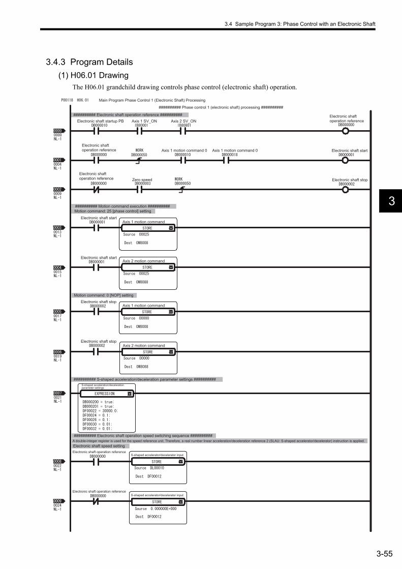
3.4 Sample Program 3: Phase Control with an Electronic Shaft
3-55
3
3.4.3 Program Details(1) H06.01 Drawing
The H06.01 grandchild drawing controls phase control (electronic shaft) operation.
Main Program Phase Control 1 (Electronic Shaft) Processing
########## Phase control 1 (electronic shaft) processing ##########
########## Electronic shaft operation reference ##########Electronic shaft startup PB
Axis 1 motion command
Axis 2 SV_ON
Electronic shaft start
Electronic shaft stop Zero speed
Electronic shaft start
Axis 2 motion command
Axis 1 motion command
Axis 2 motion command
Electronic shaft stop
########## Motion command execution ##########Motion command: 25 [phase control] setting
Axis 1 SV_ON
Axis 1 motion command 0 Axis 1 motion command 0
Electronic shaft start
Motion command: 0 [NOP] setting
########## S-shaped acceleration/deceleration parameter settings ##########
########## Electronic shaft operation speed switching sequence ##########
Electronic shaft speed setting
Electronic shaft stop
A double-integer register is used for the speed reference unit. Therefore, a real number linear acceleration/deceleration reference 2 (SLAU: S-shaped accelerator/decelerator) instruction is applied.
Electronic shaft operation reference
Electronic shaft operation reference
S-shaped accelerator/decelerator input
S-shaped accelerator/decelerator input
Electronic shaft operation reference
Electronic shaft operation reference
S-shaped acceleration/deceleration parameter settings
Electronic shaft operation reference

3 System Startup
3.4.3 Program Details
3-56
Main Program Phase Control 1 (Electronic Shaft) Processing
Zero speed
Zero speed Zero speed
########## Inter-axial error monitor ##########
Axis 1 and 2 speed reference settings Electronic shaft operation reference
########## Axis 1 and 2 speed reference settings ##########
S-shaped accelerator/decelerator output
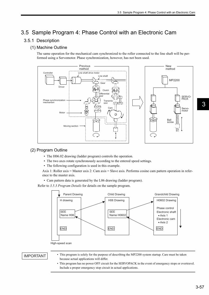
3.5 Sample Program 4: Phase Control with an Electronic Cam
3-57
3
3.5 Sample Program 4: Phase Control with an Electronic Cam3.5.1 Description
(1) Machine OutlineThe same operation for the mechanical cam synchronized to the roller connected to the line shaft will be per-formed using a Servomotor. Phase synchronization, however, has not been used.
(2) Program Outline• The H06.02 drawing (ladder program) controls the operation.• The two axes rotate synchronously according to the entered speed settings. • The following configuration is used in this example.
Axis 1: Roller axis = Master axis 2: Cam axis = Slave axis. Performs cosine cam pattern operation in refer-ence to the master axis.• Cam pattern data is generated by the L06 drawing (ladder program).
Refer to 3.5.3 Program Details for details on the sample program.
• This program is solely for the purpose of describing the MP2200 system startup. Care must be taken because actual applications will differ.
• This program has no power OFF circuit for the SERVOPACK in the event of emergency stops or overtravel. Include a proper emergency stop circuit in actual applications.
MP2200
Servo-motor
SERVO- PACK
Ball screw
Controller
Driver
Phase synchronization mechanism
Motor
Gear
Cam
Transmis-sion
Clutch Differential gear
Moving section
Line shaft Line shaft drive motor
New method
Previous method
SEEName H06
END END
SEEName H0602
END
Parent Drawing
H drawing
High-speed scan
H06 Drawing
Child Drawing
H0602 Drawing
Grandchild Drawing
Phase control Electronic shaft
• Axis 1 Electronic cam
• Axis 2
IMPORTANT

3 System Startup
3.5.2 Operation
3-58
3.5.2 Operation(1) Tuning Panel
1. Use the Tuning Panel Window for the H06 drawing to check operations, just as described in 3.4.2 Opera-tion. Right-click the H06 drawing in the High Scan Programs Folder and select Open - Tuning Panel.
2. The Tuning Panel Window for the H06 drawing will be displayed.
The details on the Tuning Panel Window display are shown in the following table.
Input position and current value.
No. Data Name S Display Definition
Current Value Units Lower Limit Upper Limit REG-No. DWG
1 ***************Common monitor*************** XXXXX 00000 00000 32767 DW00010 L
2 Axis 1 operation ready ON/OFF ON IB80000
3 Axis 2 operation ready ON/OFF ON IB80800
4 Axis 1 current position XXXXXXXXXX 0000000000 −2147483648 2147483647 IL8016
5 Axis 2 current position XXXXXXXXXX 0000000000 −2147483648 2147483647 IL8096
6 ***************Common operation*************** XXXXX 00000 00000 32767 DW00010 L
7 Servo ON PB S ON/OFF OFF MB300000
8 Alarm reset PB S ON/OFF OFF MB300001
9 ************Phase control (electronic shaft))************ XXXXX 00000 00000 32767 DW00010 L
10 Electronic shaft start S ON/OFF OFF DB000010 H06.01
11 Speed setting (motor rated speed: 30000 mm/min) S XXXXXX 000000 mm/min −030000 030000 DL00010 H06.02
12 *************Phase control (electronic cam)************* XXXXX 0000 0000 32767 DW00010 L
13 Electronic cam start S ON/OFF OFF DB000010 H06.02
14 Main axis speed setting (motor rated speed: 30000 mm/min) S XXXXXX 00000 mm/min 00000 030000 DL00010 H06.01
15 Cam axis: amplitude setting (double amplitude) S XXX.XXX 010.000 mm 000.000 999.999 ML30200
16 Cam axis: main axis moving amount per cycle S XXXXX.XXX 00500.000 mm 00000.000 50000.000 ML30202

3.5 Sample Program 4: Phase Control with an Electronic Cam
3-59
3
(2) Confirming OperationUse the following procedure to confirm operation.
The process for confirming operation will be explained based on the above procedure.1. Switching between Servo ON and Servo OFF
Change the current value setting for Servo ON PB from OFF to ON on the Tuning Panel Window. The Servomotor will turn ON and the Servo will be clamped.
2. Entering Cam DataEnter any value within the setting range for the Tuning Panel Window items listed below. The cam pattern is generated from these settings. Cam pattern data is not changed, however, if the Electronic Cam Start (described next) is set to ON.• Cam axis amplitude setting (double amplitude) . . . . . Setting range: 0 to 999.999• Cam axis main axis moving amount for one cycle . . . Setting range: 0 to 50000.000
3. Starting Electronic Cam OperationChange the current value for Electronic Cam Start to ON in the Tuning Panel Window. The second axis will enter Phase Control (Electronic Cam) Mode. Change the current value to OFF to exit the Phase Con-trol (Electronic Cam) Mode.
4. Entering Main Axis Speed SettingsChange the current value for the Main Axis Speed Setting in the Tuning Panel Window to any value between −30000 to 30000. The value set will be the master axis speed and the axis operation will start.
Actual Application ProgramsPrograms must be created in actual applications to monitor and control registers that correspond to the signals and data listed above.The register numbers that correspond to the signals used in this sample program will be the register numbers displayed under REG-No. next to DWG at the right of the Tuning Panel window.
Turn ON the Servo.
Enter electronic cam settings data.
Turn ON electronic cam start.
Enter main axis speed settings.
Confirm operation.
INFO

3 System Startup
3.5.3 Program Details
3-60
3.5.3 Program Details(1) H06.02 Drawing
The H06.02 grandchild drawing controls phase control (electronic cam) operation.
Axis 2: Slave axis = phase control (electronic cam) Axis 1: Master axis = phase control (electronic shaft)
########## Explanation ##########
Main Program Phase Control 2 (Electronic Cam) Processing
########## Phase control 2 (electronic cam) processing ##########
########## Phase control operation reference ##########Startup PB
Axis 1 motion command
Axis 2 SV_ON
Electronic cam start
Electronic cam stop Zero speed
Electronic cam start
Axis 2 motion command
Axis 1 motion command
Axis 2 motion command
Electronic cam stop
########## Motion command execution ##########Motion command: 25 [phase control] setting
Axis 1 SV_ON Operation reference
Operation reference Axis 1 motion command 0 Axis 1 motion command 0
Operation reference
Electronic cam start
Motion command: 0 [NOP] setting
########## Slave axis phase generation calculation disabled (Electronic Cam Mode) ##########
Electronic cam stop
########## Master axis speed reference generation ##########Master axis linear acceleration/deceleration parameter settings
Linear acceleration/deceleration parameter settings
Master axis speed settings Operation reference
Linear accelerator/decelerator input
Axis 2 phase generation disabled
Zero speed
Operation reference
Cam operation reference

3.5 Sample Program 4: Phase Control with an Electronic Cam
3-61
3
Main Program Phase Control 2 (Electronic Cam) Processing
########## Slave axiscontrol circuit ##########
Master axis increment calculation
Cam operation reference
Operation reference
Operation reference
Zero speed
Zero speed Zero speed
########## Electronic cam phase generation ##########
Axis 1 speed reference setting
Linear accelerator/decelerator input
Linear accelerator/decelerator input
Electronic cam phase
Master axis position FB (previous value)
Increment for one scan by master axis
Master axis position FB (previous value)
Electronic cam phase
Cycle detection

3 System Startup
3.5.3 Program Details
3-62
Main Program Phase Control 2 (Electronic Cam) Processing
Forward detection Electronic cam phase
Reverse detection Electronic cam phase
Electronic cam phase
Electronic cam phase
Slave axis cam displacement generation
Slave axis cam displacement
Cam operation reference Axis 2 phase compensation
Cam operation reference Axis 2 phase compensation
########## Slave axisreference speed generation ##########
Increment for one scan by slave axis
Slave axis cam displacement (previous)
Cam operation reference Cam speed calculation and settings

3.5 Sample Program 4: Phase Control with an Electronic Cam
3-63
3
(2) L DrawingThe L parent drawing is in the low-speed scan and controls the overall sample program.
(3) L06 DrawingThe L06 child drawing generates cam pattern data for phase control (electronic cam) operation.
########## Electronic cam table data generation ##########
Main Program Low-speed Main Program
########## Low-speed main program ##########
Main Program Electronic Cam Table Data Generation
Cam operation reference
########## Electronic cam table data generation ##########
########## Cam table generation (head data)##########
Cam table (head data)
########## Cam table generation (later data) ##########
Cam displacement calculation
Phase (deg)
Displacement calculation workpiece
Cam displacement calculation and table settings

4-1
4
4Module Specifications
This chapter explains detailed specifications for the Basic Unit and Optional Modules of the MP2200.
4.1 General Specifications - - - - - - - - - - - - - - - - - - - - - - - - - - - - - - - - - - - - - 4-34.1.1 Hardware Specifications - - - - - - - - - - - - - - - - - - - - - - - - - - - - - - - - - - - - - - - - - - - - - 4-34.1.2 Function List - - - - - - - - - - - - - - - - - - - - - - - - - - - - - - - - - - - - - - - - - - - - - - - - - - - - - 4-4
4.2 Base Unit - - - - - - - - - - - - - - - - - - - - - - - - - - - - - - - - - - - - - - - - - - - - - - - 4-54.2.1 Outline of Functions - - - - - - - - - - - - - - - - - - - - - - - - - - - - - - - - - - - - - - - - - - - - - - - - 4-54.2.2 LED Indicators - - - - - - - - - - - - - - - - - - - - - - - - - - - - - - - - - - - - - - - - - - - - - - - - - - - 4-54.2.3 Hardware Specifications - - - - - - - - - - - - - - - - - - - - - - - - - - - - - - - - - - - - - - - - - - - - - 4-6
4.3 CPU-01 Module - - - - - - - - - - - - - - - - - - - - - - - - - - - - - - - - - - - - - - - - - - 4-74.3.1 Outline of Functions - - - - - - - - - - - - - - - - - - - - - - - - - - - - - - - - - - - - - - - - - - - - - - - - 4-74.3.2 LED Indicators and Switch Settings - - - - - - - - - - - - - - - - - - - - - - - - - - - - - - - - - - - - - 4-74.3.3 Hardware Specifications - - - - - - - - - - - - - - - - - - - - - - - - - - - - - - - - - - - - - - - - - - - - - 4-94.3.4 Functions and Specifications - - - - - - - - - - - - - - - - - - - - - - - - - - - - - - - - - - - - - - - - 4-10
4.4 SVB-01 Module - - - - - - - - - - - - - - - - - - - - - - - - - - - - - - - - - - - - - - - - - 4-134.4.1 Outline of Functions - - - - - - - - - - - - - - - - - - - - - - - - - - - - - - - - - - - - - - - - - - - - - - - 4-134.4.2 LED Indicators and Switch Settings - - - - - - - - - - - - - - - - - - - - - - - - - - - - - - - - - - - - 4-134.4.3 Hardware Specifications - - - - - - - - - - - - - - - - - - - - - - - - - - - - - - - - - - - - - - - - - - - - 4-154.4.4 Function Lists - - - - - - - - - - - - - - - - - - - - - - - - - - - - - - - - - - - - - - - - - - - - - - - - - - - 4-16
4.5 SVA-01 Module - - - - - - - - - - - - - - - - - - - - - - - - - - - - - - - - - - - - - - - - - 4-184.5.1 Outline of Functions - - - - - - - - - - - - - - - - - - - - - - - - - - - - - - - - - - - - - - - - - - - - - - - 4-184.5.2 LED Indicators and Switch Settings - - - - - - - - - - - - - - - - - - - - - - - - - - - - - - - - - - - - 4-184.5.3 Hardware Specifications - - - - - - - - - - - - - - - - - - - - - - - - - - - - - - - - - - - - - - - - - - - - 4-194.5.4 Function Lists - - - - - - - - - - - - - - - - - - - - - - - - - - - - - - - - - - - - - - - - - - - - - - - - - - - 4-20
4.6 LIO-01 Module - - - - - - - - - - - - - - - - - - - - - - - - - - - - - - - - - - - - - - - - - - 4-224.6.1 Outline of Functions - - - - - - - - - - - - - - - - - - - - - - - - - - - - - - - - - - - - - - - - - - - - - - - 4-224.6.2 LED Indicators and Switch Settings - - - - - - - - - - - - - - - - - - - - - - - - - - - - - - - - - - - - 4-224.6.3 Hardware Specifications - - - - - - - - - - - - - - - - - - - - - - - - - - - - - - - - - - - - - - - - - - - - 4-24
4.7 LIO-02 Module - - - - - - - - - - - - - - - - - - - - - - - - - - - - - - - - - - - - - - - - - - 4-254.7.1 Outline of Functions - - - - - - - - - - - - - - - - - - - - - - - - - - - - - - - - - - - - - - - - - - - - - - - 4-254.7.2 LED Indicators and Switch Settings - - - - - - - - - - - - - - - - - - - - - - - - - - - - - - - - - - - - 4-254.7.3 Hardware Specifications - - - - - - - - - - - - - - - - - - - - - - - - - - - - - - - - - - - - - - - - - - - - 4-27
4 Module Specifications
4-2
4.8 LIO-01 and LIO-02 Module Counter Functions - - - - - - - - - - - - - - - - - - - 4-284.8.1 Outline of Functions - - - - - - - - - - - - - - - - - - - - - - - - - - - - - - - - - - - - - - - - - - - - - - -4-284.8.2 Counter Function Details - - - - - - - - - - - - - - - - - - - - - - - - - - - - - - - - - - - - - - - - - - - -4-304.8.3 Electronic Gear Function - - - - - - - - - - - - - - - - - - - - - - - - - - - - - - - - - - - - - - - - - - - -4-334.8.4 Counter Parameters - - - - - - - - - - - - - - - - - - - - - - - - - - - - - - - - - - - - - - - - - - - - - - -4-37
4.9 LIO-04 Module - - - - - - - - - - - - - - - - - - - - - - - - - - - - - - - - - - - - - - - - - - 4-404.9.1 Outline of Functions - - - - - - - - - - - - - - - - - - - - - - - - - - - - - - - - - - - - - - - - - - - - - - -4-404.9.2 LED Indicators and Switch Settings - - - - - - - - - - - - - - - - - - - - - - - - - - - - - - - - - - - -4-404.9.3 Hardware Specifications - - - - - - - - - - - - - - - - - - - - - - - - - - - - - - - - - - - - - - - - - - - -4-41
4.10 218IF-01 Module - - - - - - - - - - - - - - - - - - - - - - - - - - - - - - - - - - - - - - - 4-424.10.1 Outline of Functions - - - - - - - - - - - - - - - - - - - - - - - - - - - - - - - - - - - - - - - - - - - - - -4-424.10.2 LED Indicators and Switch Settings - - - - - - - - - - - - - - - - - - - - - - - - - - - - - - - - - - -4-424.10.3 Hardware Specifications - - - - - - - - - - - - - - - - - - - - - - - - - - - - - - - - - - - - - - - - - - -4-44
4.11 217IF-01 Module - - - - - - - - - - - - - - - - - - - - - - - - - - - - - - - - - - - - - - - - 4-454.11.1 Outline of Functions - - - - - - - - - - - - - - - - - - - - - - - - - - - - - - - - - - - - - - - - - - - - - -4-454.11.2 LED Indicators and Switch Settings - - - - - - - - - - - - - - - - - - - - - - - - - - - - - - - - - - -4-454.11.3 Hardware Specifications - - - - - - - - - - - - - - - - - - - - - - - - - - - - - - - - - - - - - - - - - - -4-47
4.12 260IF-01 Module - - - - - - - - - - - - - - - - - - - - - - - - - - - - - - - - - - - - - - - 4-484.12.1 Outline of Functions - - - - - - - - - - - - - - - - - - - - - - - - - - - - - - - - - - - - - - - - - - - - - -4-484.12.2 LED Indicators and Switch Settings - - - - - - - - - - - - - - - - - - - - - - - - - - - - - - - - - - -4-484.12.3 Hardware Specifications - - - - - - - - - - - - - - - - - - - - - - - - - - - - - - - - - - - - - - - - - - -4-50
4.13 261IF-01 Module - - - - - - - - - - - - - - - - - - - - - - - - - - - - - - - - - - - - - - - 4-524.13.1 Outline of Functions - - - - - - - - - - - - - - - - - - - - - - - - - - - - - - - - - - - - - - - - - - - - - -4-524.13.2 LED Indicators and Switch Settings - - - - - - - - - - - - - - - - - - - - - - - - - - - - - - - - - - -4-524.13.3 Hardware Specifications - - - - - - - - - - - - - - - - - - - - - - - - - - - - - - - - - - - - - - - - - - -4-54
4.14 EXIOIF Module - - - - - - - - - - - - - - - - - - - - - - - - - - - - - - - - - - - - - - - - - 4-564.14.1 Outline of Functions - - - - - - - - - - - - - - - - - - - - - - - - - - - - - - - - - - - - - - - - - - - - - -4-564.14.2 LED Indicators and Switch Settings - - - - - - - - - - - - - - - - - - - - - - - - - - - - - - - - - - -4-564.14.3 Hardware Specifications - - - - - - - - - - - - - - - - - - - - - - - - - - - - - - - - - - - - - - - - - - -4-56
4.15 External Appearance - - - - - - - - - - - - - - - - - - - - - - - - - - - - - - - - - - - - 4-574.15.1 Basic Unit - - - - - - - - - - - - - - - - - - - - - - - - - - - - - - - - - - - - - - - - - - - - - - - - - - - - -4-574.15.2 Mounting Optional Module Connectors - - - - - - - - - - - - - - - - - - - - - - - - - - - - - - - - -4-58
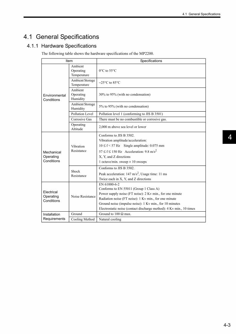
4.1 General Specifications
4-3
4
4.1 General Specifications4.1.1 Hardware Specifications
The following table shows the hardware specifications of the MP2200.
Item Specifications
Environmental Conditions
Ambient Operating Temperature
0°C to 55°C
Ambient Storage Temperature −25°C to 85°C
Ambient Operating Humidity
30% to 95% (with no condensation)
Ambient Storage Humidity 5% to 95% (with no condensation)
Pollution Level Pollution level 1 (conforming to JIS B 3501)Corrosive Gas There must be no combustible or corrosive gas.Operating Altitude 2,000 m above sea level or lower
Mechanical Operating Conditions
Vibration Resistance
Conforms to JIS B 3502.Vibration amplitude/acceleration:10 ≤ f < 57 Hz Single amplitude: 0.075 mm
57 ≤ f ≤ 150 Hz Acceleration: 9.8 m/s2
X, Y, and Z directions1 octave/min. sweep × 10 sweeps
Shock Resistance
Conforms to JIS B 3502.
Peak acceleration: 147 m/s2, Usage time: 11 msTwice each in X, Y, and Z directions
Electrical Operating Conditions
Noise Resistance
EN 61000-6-2Conforms to EN 55011 (Group 1 Class A)Power supply noise (FT noise): 2 Kv min., for one minuteRadiation noise (FT noise): 1 Kv min., for one minuteGround noise (impulse noise): 1 Kv min., for 10 minutesElectrostatic noise (contact discharge method): 4 Kv min., 10 times
Installation Requirements
Ground Ground to 100 Ω max.Cooling Method Natural cooling

4 Module Specifications
4.1.2 Function List
4-4
4.1.2 Function List(1) PLC Functions and Specifications
The following table shows the PLC functions and specifications.
Item Functions and SpecificationsControl Method Sequence: High-speed and low-speed scansProgramming Language
Ladder diagram: Relay circuitsText-type language: Numeric operations, logic operations, etc.
Scanning
Two scan levels: High-speed scan and low-speed scanHigh-speed scan time: 0.5 to 32 ms (Integral multiple of MECHATROLINK communica-tion cycle)Low-speed scan time: 2 to 300 ms (Integral multiple of MECHATROLINK communica-tion cycle)
User Drawings, Func-tions, and Motion Pro-grams
Startup drawings (DWG.A):
Interrupt drawings (DWG.I):
High-speed scan process drawings (DWG.H):Low-speed scan process drawings (DWG.L):Number of steps:User functions:Motion programs:
64 drawings max. Up to three hierarchical drawing levels, 64 drawings max. Up to three hierarchical drawing levels, 200 drawings max. Up to three hierarchical draw-ing levels, 500 drawings max. Up to three hierarchical draw-ing levels, 1000 steps/drawing max., Up to 500, Up to 256
Revision history of drawings and motion programsSecurity function for drawings and motion programs
Data Memory
Common data (M) registers:System (S) registers:Drawing local (D) registers:Drawing constant (#) registers: Input (I) registers:Output (O) registers:Constant (C) registers:
64 Kwords, 8 Kwords, 16 Kwords/drawing max., 16 Kwords/drawing max., 5 Kwords (including internal input registers), 5 Kwords (including internal output registers), 16 Kwords
Trace Memory Data trace: 128 Kwords (4 groups with 32 Kwords each). Up to 16 points can be defined.
Memory Backup
Program memory: Flash memory: 8 MBytes (User area: 5.5 MBytes), definition files, ladder programs, motion programs, etc. Data other than battery backup data
Data memory: Battery backup: 256 Kbytes, M registers, S registers, alarm history, trace data
Data Type
Bit (relay): ON/OFFInteger: −32768 to +32767Double-length integer: −2147483648 to +2147483647Real number: ± (1.175E-38 to 3.402E+38)
Register Designation Method
Register number: Direct designation of register numberSymbol designation: Up to 8 alphanumeric characters (200 symbols/drawing max.)Automatic number assignment and automatic symbols
Instructions
Program control instructions: 14 instructions, Direct I/O instructions: 2 instructions, Relay circuit instructions: 14 instructions (including set and reset coils),Logic operation instructions: 3 instructions, Numeric operation instructions: 16 instructions, Numeric conversion instructions: 9 instructions, Numeric comparison instructions: 7 instructions, Data manipulation instructions: 14 instructions, Basic function instructions: 10 instructions, Table data manipulation instructions: 11 instructions, DDC instructions: 13 instructions, System functions: 9 instructions
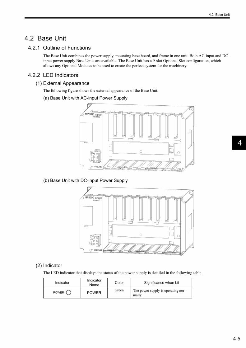
4.2 Base Unit
4-5
4
4.2 Base Unit4.2.1 Outline of Functions
The Base Unit combines the power supply, mounting base board, and frame in one unit. Both AC-input and DC-input power supply Base Units are available. The Base Unit has a 9-slot Optional Slot configuration, which allows any Optional Modules to be used to create the perfect system for the machinery.
4.2.2 LED Indicators(1) External Appearance
The following figure shows the external appearance of the Base Unit.
(a) Base Unit with AC-input Power Supply
(b) Base Unit with DC-input Power Supply
(2) IndicatorThe LED indicator that displays the status of the power supply is detailed in the following table.
MP2200 MBU-01POWER
100/200V
BATTEY
AC
MP2200 MBU-02POWER
BATTEY
DC 0
Indicator Indicator Name Color Significance when Lit
POWERGreen The power supply is operating nor-
mally.POWER

4 Module Specifications
4.2.3 Hardware Specifications
4-6
4.2.3 Hardware SpecificationsThe following table shows the hardware specifications of the Base Unit.
Item SpecificationsName Base Unit (AC-input power supply) Base Unit (DC-input power supply)Model JEPMC-BU2200 JEPMC-BU2210Abbreviation MBU-01 MBU-02
Slot Configuration
One-Rack Configuration1 slot for CPU Module8 slots for Optional Modules (including slots for Expansion Modules)
Four-Rack Configuration9 slots for Option Modules (because a CPU Module is not mounted to Racks 2, 3, and 4)
Pow
er S
uppl
y
Input Voltage 85 to 276 VAC 24 VDC (±20%)Input Current 1.5 A max. (at rated I/O) 3.0 A max. (at rated I/O)
Inrush Current 10 A max. (when completely discharged, 200-VAC input, rated output)
10 A max. (when completely discharged, rated output)
Rated Voltage 5.0 VRated Current 8.0 AOutput Current Range
0.0 to 8.0 A
Coordination Error − ±1% max.Constant Voltage Accuracy ±2% max. (including input voltage fluctuation and output load fluctuation)
Battery Battery can be installed for memory backup.Indicators POWER (green)Dimensions (mm) 240 × 130 × 108 (W × H × D)Mass 650 g
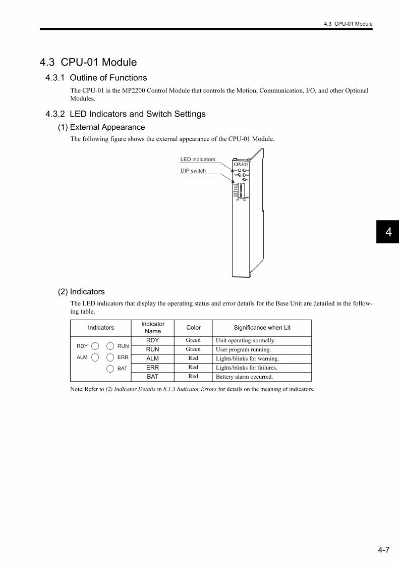
4.3 CPU-01 Module
4-7
4
4.3 CPU-01 Module4.3.1 Outline of Functions
The CPU-01 is the MP2200 Control Module that controls the Motion, Communication, I/O, and other Optional Modules.
4.3.2 LED Indicators and Switch Settings(1) External Appearance
The following figure shows the external appearance of the CPU-01 Module.
(2) IndicatorsThe LED indicators that display the operating status and error details for the Base Unit are detailed in the follow-ing table.
Note: Refer to (2) Indicator Details in 8.1.3 Indicator Errors for details on the meaning of indicators.
CPU-01RDY RUN
ERR
BAT
ALM
SUP
OFF ONSW1
MONTEST
INIT
STOP
CNFG
LED indicators
DIP switch
Indicators Indicator Name Color Significance when Lit
RDY Green Unit operating normally.RUN Green User program running.ALM Red Lights/blinks for warning.ERR Red Lights/blinks for failures.BAT Red Battery alarm occurred.
RDY
ALM
RUN
ERR
BAT
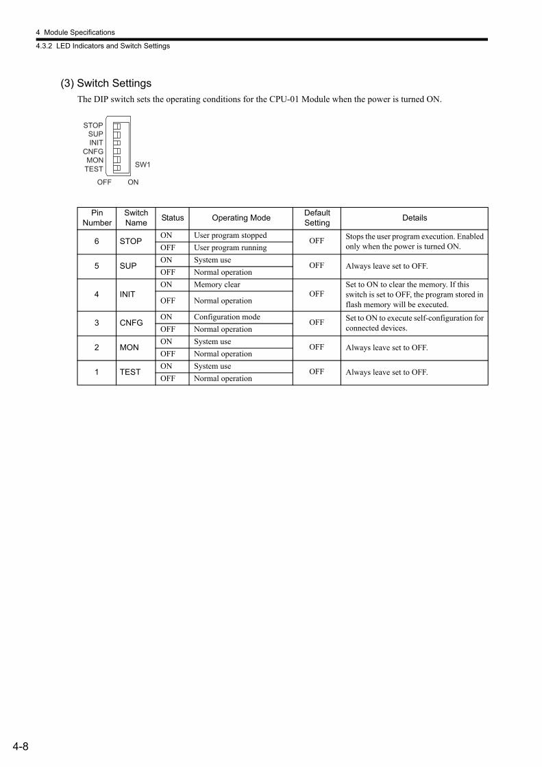
4 Module Specifications
4.3.2 LED Indicators and Switch Settings
4-8
(3) Switch SettingsThe DIP switch sets the operating conditions for the CPU-01 Module when the power is turned ON.
Pin Number
Switch Name Status Operating Mode Default
Setting Details
6 STOPON User program stopped
OFF Stops the user program execution. Enabled only when the power is turned ON.OFF User program running
5 SUPON System use
OFF Always leave set to OFF.OFF Normal operation
4 INITON Memory clear
OFFSet to ON to clear the memory. If this switch is set to OFF, the program stored in flash memory will be executed.OFF Normal operation
3 CNFGON Configuration mode
OFF Set to ON to execute self-configuration for connected devices.OFF Normal operation
2 MONON System use
OFF Always leave set to OFF.OFF Normal operation
1 TESTON System use
OFF Always leave set to OFF.OFF Normal operation
SW1
OFF ON
STOPSUPINIT
CNFGMON
TEST
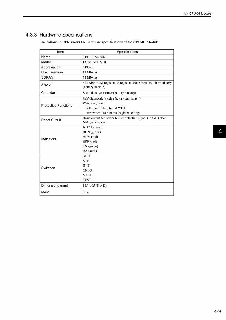
4.3 CPU-01 Module
4-9
4
4.3.3 Hardware SpecificationsThe following table shows the hardware specifications of the CPU-01 Module.
Item SpecificationsName CPU-01 ModuleModel JAPMC-CP2200Abbreviation CPU-01Flash Memory 12 MbytesSDRAM 32 Mbytes
SRAM 512 Kbytes, M registers, S registers, trace memory, alarm history (battery backup)
Calendar Seconds to year timer (battery backup)
Protective Functions
Self-diagnostic Mode (factory test switch)Watchdog timer
Software: SH4 internal WDTHardware: 0 to 510 ms (register setting)
Reset Circuit Reset output for power failure detection signal (POKH) after NMI generation.
Indicators
RDY (green)RUN (green)ALM (red)ERR (red)TX (green)BAT (red)
Switches
STOPSUPINITCNFGMONTEST
Dimensions (mm) 125 × 95 (H × D)
Mass 90 g
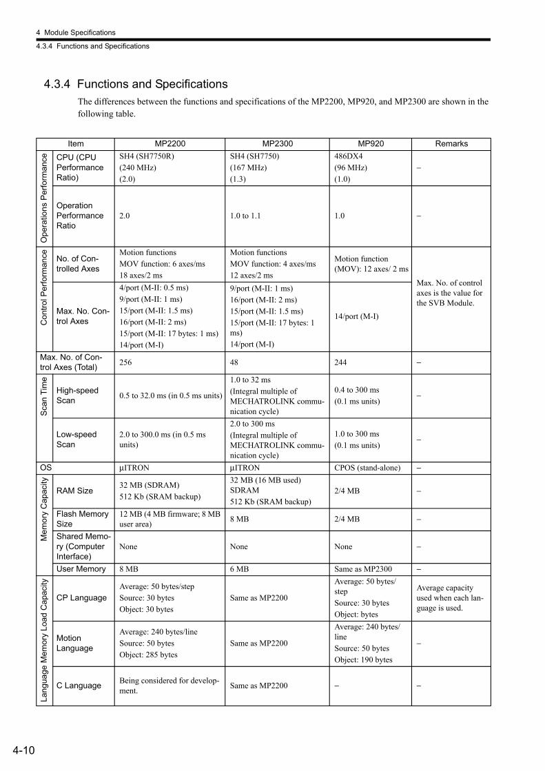
4 Module Specifications
4.3.4 Functions and Specifications
4-10
4.3.4 Functions and SpecificationsThe differences between the functions and specifications of the MP2200, MP920, and MP2300 are shown in the following table.
Item MP2200 MP2300 MP920 Remarks
Ope
ratio
ns P
erfo
rman
ce CPU (CPU Performance Ratio)
SH4 (SH7750R)(240 MHz)(2.0)
SH4 (SH7750)(167 MHz)(1.3)
486DX4(96 MHz)(1.0)
−
Operation Performance Ratio
2.0 1.0 to 1.1 1.0 −
Con
trol P
erfo
rman
ce No. of Con-trolled Axes
Motion functionsMOV function: 6 axes/ms18 axes/2 ms
Motion functionsMOV function: 4 axes/ms12 axes/2 ms
Motion function (MOV): 12 axes/ 2 ms
Max. No. of control axes is the value for the SVB Module.
Max. No. Con-trol Axes
4/port (M-II: 0.5 ms)9/port (M-II: 1 ms)15/port (M-II: 1.5 ms)16/port (M-II: 2 ms)15/port (M-II: 17 bytes: 1 ms)14/port (M-I)
9/port (M-II: 1 ms)16/port (M-II: 2 ms)15/port (M-II: 1.5 ms) 15/port (M-II: 17 bytes: 1 ms)14/port (M-I)
14/port (M-I)
Max. No. of Con-trol Axes (Total) 256 48 244 −
Scan
Tim
e
High-speed Scan 0.5 to 32.0 ms (in 0.5 ms units)
1.0 to 32 ms(Integral multiple of MECHATROLINK commu-nication cycle)
0.4 to 300 ms(0.1 ms units)
−
Low-speed Scan
2.0 to 300.0 ms (in 0.5 ms units)
2.0 to 300 ms(Integral multiple of MECHATROLINK commu-nication cycle)
1.0 to 300 ms(0.1 ms units)
−
OS µITRON µITRON CPOS (stand-alone) −
Mem
ory
Cap
acity
RAM Size32 MB (SDRAM)512 Kb (SRAM backup)
32 MB (16 MB used) SDRAM512 Kb (SRAM backup)
2/4 MB −
Flash Memory Size
12 MB (4 MB firmware; 8 MB user area) 8 MB 2/4 MB −
Shared Memo-ry (Computer Interface)
None None None −
User Memory 8 MB 6 MB Same as MP2300 −
Lang
uage
Mem
ory
Load
Cap
acity
CP LanguageAverage: 50 bytes/stepSource: 30 bytesObject: 30 bytes
Same as MP2200
Average: 50 bytes/stepSource: 30 bytesObject: bytes
Average capacity used when each lan-guage is used.
Motion Language
Average: 240 bytes/lineSource: 50 bytesObject: 285 bytes
Same as MP2200
Average: 240 bytes/lineSource: 50 bytesObject: 190 bytes
−
C Language Being considered for develop-ment. Same as MP2200 − −
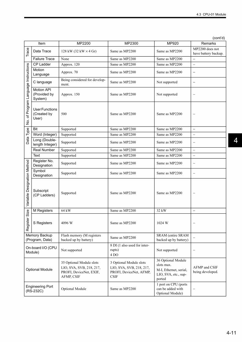
4.3 CPU-01 Module
4-11
4
Trac
e
Data Trace 128 kW (32 kW × 4 Gr) Same as MP2200 Same as MP2200 MP2200 does not have battery backup.
Failure Trace None Same as MP2200 Same as MP2200 −
No.
of P
rogr
am L
angu
age
Inst
ruct
ions CP Ladder Approx. 120 Same as MP2200 Same as MP2200 −
Motion Language Approx. 70 Same as MP2200 Same as MP2200 −
C language Being considered for develop-ment. Same as MP2200 Not supported −
Motion API (Provided by System)
Approx. 150 Same as MP2200 Not supported −
User Functions (Created by User)
500 Same as MP2200 Same as MP2200 −
Dat
a Ty
pe Bit Supported Same as MP2200 Same as MP2200 −Word (Integer) Supported Same as MP2200 Same as MP2200 −Long (Double-length Integer) Supported Same as MP2200 Same as MP2200 −
Real Number Supported Same as MP2200 Same as MP2200 −Text Supported Same as MP2200 Same as MP2200 −
Varia
ble
Des
igna
tion
Met
hod Register No.
Designation Supported Same as MP2200 Same as MP2200 −
Symbol Designation Supported Same as MP2200 Same as MP2200 −
Subscript (CP Ladders) Supported Same as MP2200 Same as MP2200 −
Reg
iste
r Siz
e M Registers 64 kW Same as MP2200 32 kW −
S Registers 4096 W Same as MP2200 1024 W −
Memory Backup (Program, Data)
Flash memory (M registers backed up by battery) Same as MP2200 SRAM (entire SRAM
backed up by battery) −
On-board I/O (CPU Module) Not supported
8 DI (1 also used for inter-rupts)4 DO
Not supported −
Optional Module
35 Optional Module slotsLIO, SVA, SVB, 218, 217, PROFI, DeviceNet, EXIF, AFMP, CSIF
3 Optional Module slotsLIO, SVA, SVB, 218, 217, PROFI, DeviceNet, AFMP, CSIF
36 Optional Module slots max.M-I, Ethernet, serial, LIO, SVA, etc., sup-ported
AFMP and CSIF being developed.
Engineering Port (RS-232C) Optional Module Same as MP2200
1 port on CPU (ports can be added with Optional Module)
−
(cont’d)Item MP2200 MP2300 MP920 Remarks
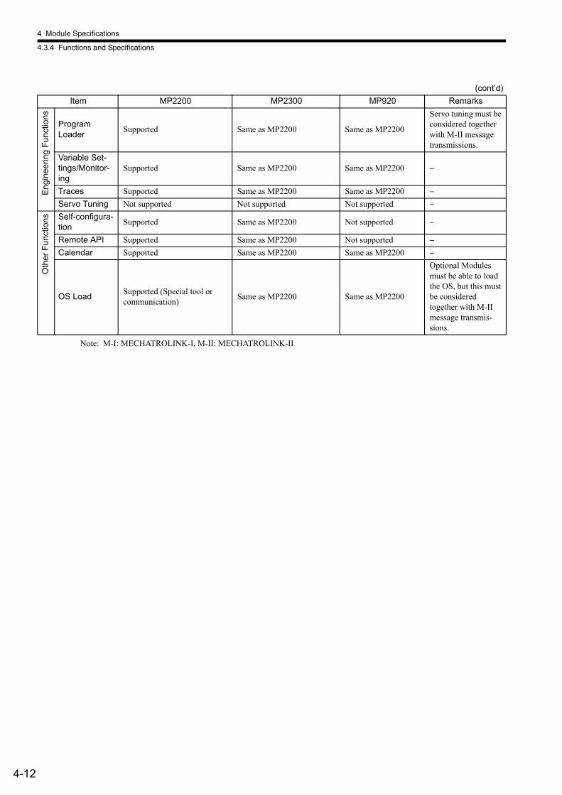
4 Module Specifications
4.3.4 Functions and Specifications
4-12
Note: M-I: MECHATROLINK-I, M-II: MECHATROLINK-II
Engi
neer
ing
Func
tions
Program Loader Supported Same as MP2200 Same as MP2200
Servo tuning must be considered together with M-II message transmissions.
Variable Set-tings/Monitor-ing
Supported Same as MP2200 Same as MP2200 −
Traces Supported Same as MP2200 Same as MP2200 −Servo Tuning Not supported Not supported Not supported −
Oth
er F
unct
ions Self-configura-
tion Supported Same as MP2200 Not supported −
Remote API Supported Same as MP2200 Not supported −Calendar Supported Same as MP2200 Same as MP2200 −
OS Load Supported (Special tool or communication) Same as MP2200 Same as MP2200
Optional Modules must be able to load the OS, but this must be considered together with M-II message transmis-sions.
(cont’d)Item MP2200 MP2300 MP920 Remarks
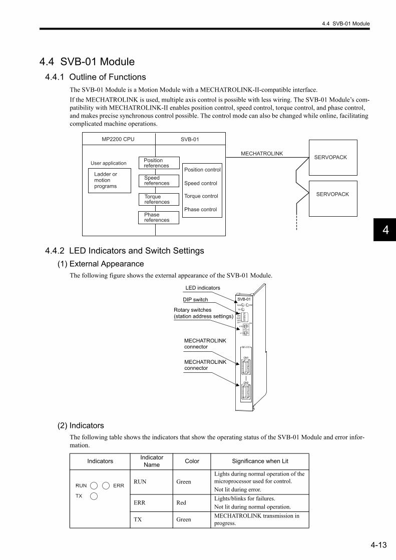
4.4 SVB-01 Module
4-13
4
4.4 SVB-01 Module4.4.1 Outline of Functions
The SVB-01 Module is a Motion Module with a MECHATROLINK-II-compatible interface.If the MECHATROLINK is used, multiple axis control is possible with less wiring. The SVB-01 Module’s com-patibility with MECHATROLINK-II enables position control, speed control, torque control, and phase control, and makes precise synchronous control possible. The control mode can also be changed while online, facilitating complicated machine operations.
4.4.2 LED Indicators and Switch Settings(1) External Appearance
The following figure shows the external appearance of the SVB-01 Module.
(2) IndicatorsThe following table shows the indicators that show the operating status of the SVB-01 Module and error infor-mation.
MP2200 CPU SVB-01
MECHATROLINK
Ladder or motion programs Speed control
Position control
Phase control
SERVOPACK
Torque control
Position references
Speed references
Phase references
Torque references
SERVOPACK
User application
SVB-01
TX
ERRRUN
SPDSIZEM/S
ONOFF
10
1
M-I/II
CN1
CN2
LED indicators
Rotary switches (station address settings)
DIP switch
MECHATROLINK connector
MECHATROLINK connector
Indicators Indicator Name Color Significance when Lit
RUN GreenLights during normal operation of the microprocessor used for control.Not lit during error.
ERR RedLights/blinks for failures.Not lit during normal operation.
TX Green MECHATROLINK transmission in progress.
RUN
TX
ERR
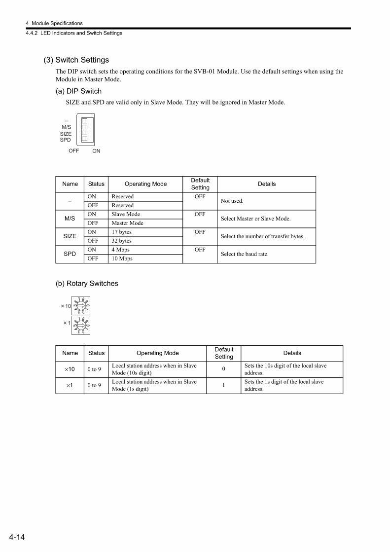
4 Module Specifications
4.4.2 LED Indicators and Switch Settings
4-14
(3) Switch SettingsThe DIP switch sets the operating conditions for the SVB-01 Module. Use the default settings when using the Module in Master Mode.
(a) DIP SwitchSIZE and SPD are valid only in Slave Mode. They will be ignored in Master Mode.
(b) Rotary Switches
Name Status Operating Mode Default Setting Details
−ON Reserved OFF
Not used.OFF Reserved
M/SON Slave Mode OFF
Select Master or Slave Mode.OFF Master Mode
SIZEON 17 bytes OFF
Select the number of transfer bytes.OFF 32 bytes
SPDON 4 Mbps OFF
Select the baud rate.OFF 10 Mbps
Name Status Operating Mode Default Setting Details
×10 0 to 9 Local station address when in Slave Mode (10s digit)
0 Sets the 10s digit of the local slave address.
×1 0 to 9 Local station address when in Slave Mode (1s digit)
1 Sets the 1s digit of the local slave address.
OFF ON
SPDSIZEM/S
10
1
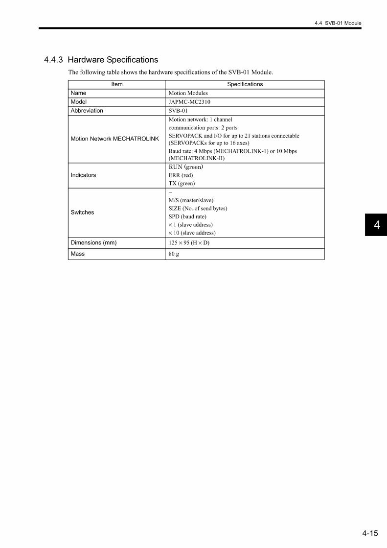
4.4 SVB-01 Module
4-15
4
4.4.3 Hardware SpecificationsThe following table shows the hardware specifications of the SVB-01 Module.
Item SpecificationsName Motion ModulesModel JAPMC-MC2310Abbreviation SVB-01
Motion Network MECHATROLINK
Motion network: 1 channelcommunication ports: 2 portsSERVOPACK and I/O for up to 21 stations connectable (SERVOPACKs for up to 16 axes)Baud rate: 4 Mbps (MECHATROLINK-1) or 10 Mbps (MECHATROLINK-II)
IndicatorsRUN (green)ERR (red)TX (green)
Switches
−M/S (master/slave)SIZE (No. of send bytes)SPD (baud rate)× 1 (slave address)× 10 (slave address)
Dimensions (mm) 125 × 95 (H × D)
Mass 80 g
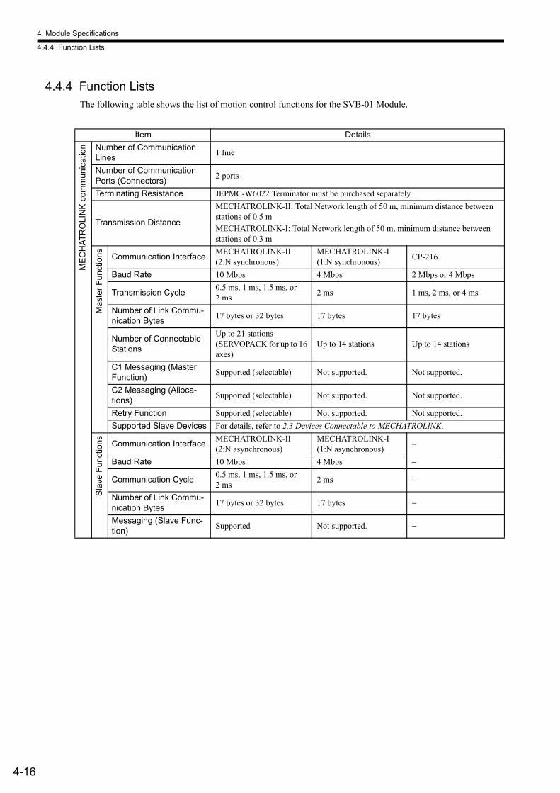
4 Module Specifications
4.4.4 Function Lists
4-16
4.4.4 Function ListsThe following table shows the list of motion control functions for the SVB-01 Module.
Item Details
MEC
HAT
RO
LIN
K co
mm
unic
atio
n Number of Communication Lines 1 line
Number of Communication Ports (Connectors) 2 ports
Terminating Resistance JEPMC-W6022 Terminator must be purchased separately.
Transmission Distance
MECHATROLINK-II: Total Network length of 50 m, minimum distance between stations of 0.5 m MECHATROLINK-I: Total Network length of 50 m, minimum distance between stations of 0.3 m
Mas
ter F
unct
ions Communication Interface MECHATROLINK-II
(2:N synchronous)MECHATROLINK-I (1:N synchronous) CP-216
Baud Rate 10 Mbps 4 Mbps 2 Mbps or 4 Mbps
Transmission Cycle 0.5 ms, 1 ms, 1.5 ms, or 2 ms 2 ms 1 ms, 2 ms, or 4 ms
Number of Link Commu-nication Bytes 17 bytes or 32 bytes 17 bytes 17 bytes
Number of Connectable Stations
Up to 21 stations (SERVOPACK for up to 16 axes)
Up to 14 stations Up to 14 stations
C1 Messaging (Master Function) Supported (selectable) Not supported. Not supported.
C2 Messaging (Alloca-tions) Supported (selectable) Not supported. Not supported.
Retry Function Supported (selectable) Not supported. Not supported. Supported Slave Devices For details, refer to 2.3 Devices Connectable to MECHATROLINK.
Slav
e Fu
nctio
ns Communication Interface MECHATROLINK-II (2:N asynchronous)
MECHATROLINK-I (1:N asynchronous) −
Baud Rate 10 Mbps 4 Mbps −
Communication Cycle 0.5 ms, 1 ms, 1.5 ms, or 2 ms 2 ms −
Number of Link Commu-nication Bytes 17 bytes or 32 bytes 17 bytes −
Messaging (Slave Func-tion) Supported Not supported. −
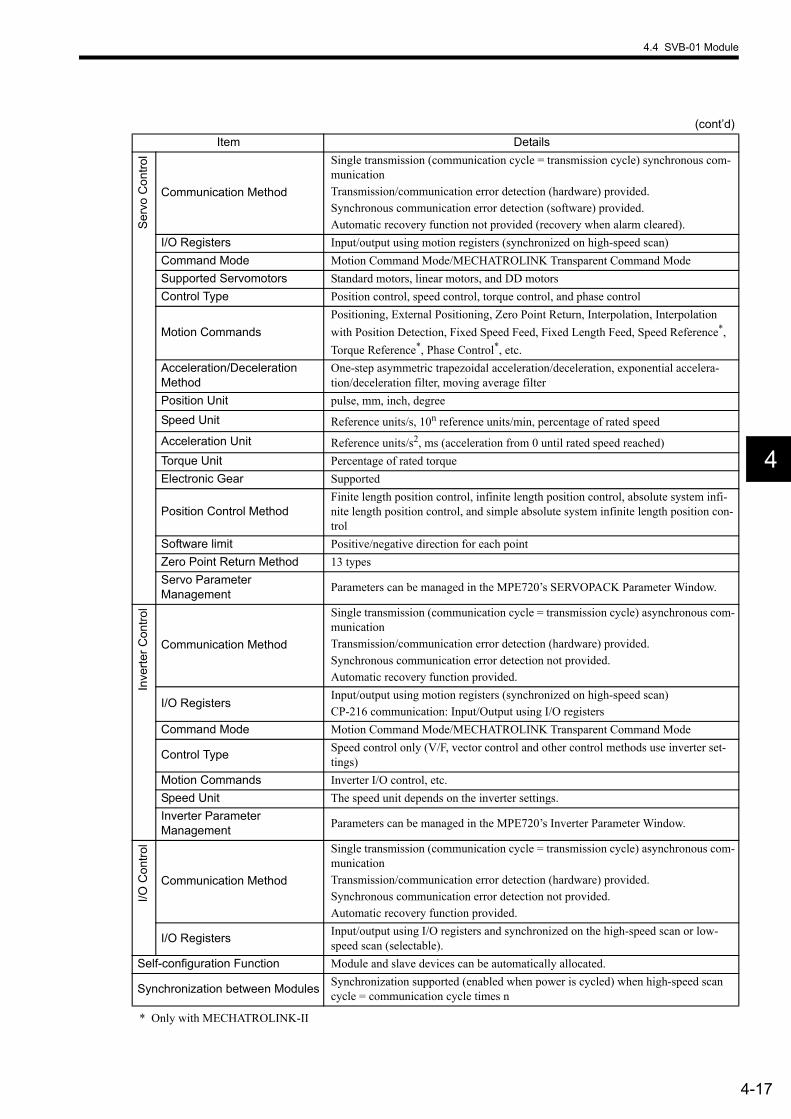
4.4 SVB-01 Module
4-17
4
* Only with MECHATROLINK-II
Serv
o C
ontro
l
Communication Method
Single transmission (communication cycle = transmission cycle) synchronous com-municationTransmission/communication error detection (hardware) provided. Synchronous communication error detection (software) provided. Automatic recovery function not provided (recovery when alarm cleared).
I/O Registers Input/output using motion registers (synchronized on high-speed scan)Command Mode Motion Command Mode/MECHATROLINK Transparent Command ModeSupported Servomotors Standard motors, linear motors, and DD motorsControl Type Position control, speed control, torque control, and phase control
Motion CommandsPositioning, External Positioning, Zero Point Return, Interpolation, Interpolation with Position Detection, Fixed Speed Feed, Fixed Length Feed, Speed Reference*, Torque Reference*, Phase Control*, etc.
Acceleration/Deceleration Method
One-step asymmetric trapezoidal acceleration/deceleration, exponential accelera-tion/deceleration filter, moving average filter
Position Unit pulse, mm, inch, degreeSpeed Unit Reference units/s, 10n reference units/min, percentage of rated speed Acceleration Unit Reference units/s2, ms (acceleration from 0 until rated speed reached) Torque Unit Percentage of rated torqueElectronic Gear Supported
Position Control MethodFinite length position control, infinite length position control, absolute system infi-nite length position control, and simple absolute system infinite length position con-trol
Software limit Positive/negative direction for each point Zero Point Return Method 13 typesServo Parameter Management Parameters can be managed in the MPE720’s SERVOPACK Parameter Window.
Inve
rter C
ontro
l
Communication Method
Single transmission (communication cycle = transmission cycle) asynchronous com-municationTransmission/communication error detection (hardware) provided. Synchronous communication error detection not provided. Automatic recovery function provided.
I/O RegistersInput/output using motion registers (synchronized on high-speed scan)CP-216 communication: Input/Output using I/O registers
Command Mode Motion Command Mode/MECHATROLINK Transparent Command Mode
Control Type Speed control only (V/F, vector control and other control methods use inverter set-tings)
Motion Commands Inverter I/O control, etc. Speed Unit The speed unit depends on the inverter settings. Inverter Parameter Management Parameters can be managed in the MPE720’s Inverter Parameter Window.
I/O C
ontro
l
Communication Method
Single transmission (communication cycle = transmission cycle) asynchronous com-municationTransmission/communication error detection (hardware) provided. Synchronous communication error detection not provided. Automatic recovery function provided.
I/O Registers Input/output using I/O registers and synchronized on the high-speed scan or low-speed scan (selectable).
Self-configuration Function Module and slave devices can be automatically allocated.
Synchronization between Modules Synchronization supported (enabled when power is cycled) when high-speed scan cycle = communication cycle times n
(cont’d)Item Details

4 Module Specifications
4.5.1 Outline of Functions
4-18
4.5 SVA-01 Module4.5.1 Outline of Functions
The SVA-01 Module is a Motion Control Module with analog outputs. Servo drives or inverters for up to 2 axes can be controlled with a single Module. The Module provides two connectors (CN1 and CN2) to connect SERVOPACKs and external I/O. Each connec-tor provides analog outputs for a speed reference and torque reference, analog inputs for feedback speed monitor-ing and torque monitoring, pulse input phases A/B/C (5-V differential), and general-purpose digital I/O. The control cycle is fixed at 500 µs to enable high-precision control regardless of the high-speed scan cycle.
4.5.2 LED Indicators and Switch Settings(1) External Appearance
The following figure shows the external appearance of the SVA-01 Module.
(2) IndicatorsThe following table shows the indicators that show the operating status of the SVA-01 Module and error informa-tion.
CN2
CN1
CN3
Servo Controls • Speed reference • Position control • Torque reference • Phase control • Zero point returnMonitor Functions
Syst
em b
us c
onne
ctor
System busInterfacesServo parameters OW IW
Two analog outputs: Speed referenceTorque reference
Two analog inputs: Speed monitorTorque reference monitor
Pulse inputs: Phases A, B, and C (5-V differential)
Six general-purpose digital inputs (2 latch inputs)
Six general-purpose digital outputsSensor ON output: 5 V/24 V
Same as above.
Serv
o co
nnec
tor
Sam
e as
ab
ove.
SVA-01
LED indicators
Servo connectors
24-V input connector
RUN
CH1
CH2
DC IN
ON
+24V
ERR
Indicators Indicator Name Color Significance When Lit
RUN GreenLights when control microprocessor is operating normally.Not lit during error.
ERR RedLights/blinks for failures.Not lit during normal operation.
RUN ERR

4.5 SVA-01 Module
4-19
4
4.5.3 Hardware SpecificationsThe following table shows the hardware specifications of the SVA-01 Module.
Item SpecificationsName Motion ModulesModel JAPMC-MC2300Abbreviation SVA-01
Servo inter-face
Digital inputs
6 inputs × 2 channels (source mode/sink mode inputs, 24 V/4.3 mA) DI_0: General-purpose input (ALM) DI_1: General-purpose input (RDY) DI_2: General-purpose input (ZERO: External latch signal input) DI_3: General-purpose input DI_4: General-purpose input DI_5: General-purpose input (EXT: External latch signal input)
Digital outputs
6 outputs × 2 channels (sink mode outputs, 24 V/100 mA) DO_0: General-purpose output (SV_ON) DO_1: General-purpose output (ALM_RST) DO_2: General-purpose output (PCON): Used as the C-SEL
(control mode select) signal. DO_3: General-purpose output DO_4: General-purpose output DO_5: General-purpose output (SEN signal): 5-V and 24-V
outputs
Pulse inputs 1 input × 2 channels, phases A/B/C, 5-V differential input, pulse rate: 4 Mpps (16 Mpps for × 4)
Analog outputs 2 outputs × 2 channels, −10 to 10 V, D/A 16 bits
Analog inputs 2 inputs × 2 channels, −10 to 10 V (applicable: −9.9 V to 9.9 V), A/D 16 bits
ConnectorsCN1: Servo connectorCN2: Servo connectorCN3: 24-V input
IndicatorsRUN (Green)ERR (Red)
Electrical op-erating condi-tions
Noise Resis-tance
Conforms to EN 61000-6-2 and EN 55011 (Group1 ClassA).Power supply noise (FT noise): 2 Kv min., for one minuteRadiation noise (FT noise): 1 Kv min., for one minuteGround noise (impulse noise): 1 Kv min., for 10 minutesElectrostatic noise (air discharge method): 8 Kv min., 10 times
Dimensions (mm) 125 × 95 (H × D)
Mass 80 g
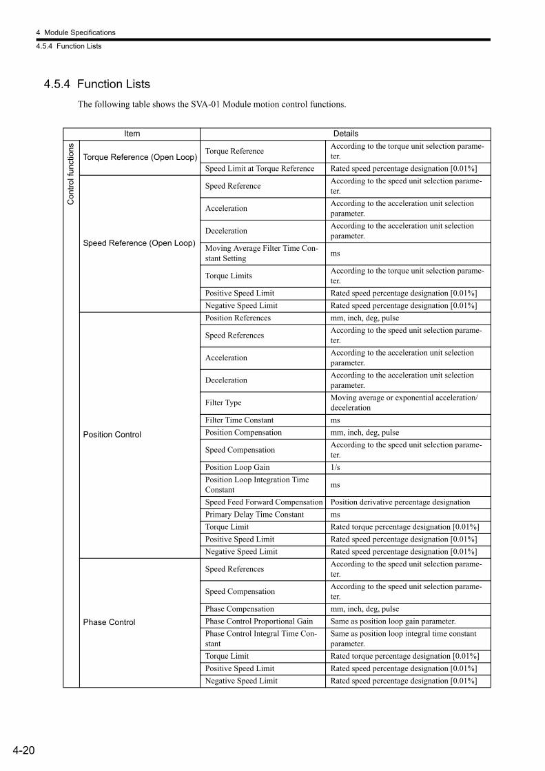
4 Module Specifications
4.5.4 Function Lists
4-20
4.5.4 Function ListsThe following table shows the SVA-01 Module motion control functions.
Item Details
Con
trol f
unct
ions
Torque Reference (Open Loop)Torque Reference According to the torque unit selection parame-
ter. Speed Limit at Torque Reference Rated speed percentage designation [0.01%]
Speed Reference (Open Loop)
Speed Reference According to the speed unit selection parame-ter.
Acceleration According to the acceleration unit selection parameter.
Deceleration According to the acceleration unit selection parameter.
Moving Average Filter Time Con-stant Setting ms
Torque Limits According to the torque unit selection parame-ter.
Positive Speed Limit Rated speed percentage designation [0.01%]Negative Speed Limit Rated speed percentage designation [0.01%]
Position Control
Position References mm, inch, deg, pulse
Speed References According to the speed unit selection parame-ter.
Acceleration According to the acceleration unit selection parameter.
Deceleration According to the acceleration unit selection parameter.
Filter Type Moving average or exponential acceleration/deceleration
Filter Time Constant msPosition Compensation mm, inch, deg, pulse
Speed Compensation According to the speed unit selection parame-ter.
Position Loop Gain 1/sPosition Loop Integration Time Constant ms
Speed Feed Forward Compensation Position derivative percentage designationPrimary Delay Time Constant msTorque Limit Rated torque percentage designation [0.01%]Positive Speed Limit Rated speed percentage designation [0.01%]Negative Speed Limit Rated speed percentage designation [0.01%]
Phase Control
Speed References According to the speed unit selection parame-ter.
Speed Compensation According to the speed unit selection parame-ter.
Phase Compensation mm, inch, deg, pulsePhase Control Proportional Gain Same as position loop gain parameter. Phase Control Integral Time Con-stant
Same as position loop integral time constant parameter.
Torque Limit Rated torque percentage designation [0.01%]Positive Speed Limit Rated speed percentage designation [0.01%]Negative Speed Limit Rated speed percentage designation [0.01%]
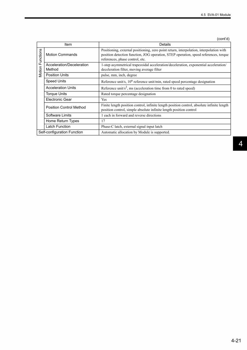
4.5 SVA-01 Module
4-21
4
Mot
ion
Func
tions
Motion CommandsPositioning, external positioning, zero point return, interpolation, interpolation with position detection function, JOG operation, STEP operation, speed references, torque references, phase control, etc.
Acceleration/Deceleration Method
1-step asymmetrical trapezoidal acceleration/deceleration, exponential acceleration/deceleration filter, moving average filter
Position Units pulse, mm, inch, degreeSpeed Units Reference unit/s, 10n reference unit/min, rated speed percentage designationAcceleration Units Reference unit/s2, ms (acceleration time from 0 to rated speed)Torque Units Rated torque percentage designationElectronic Gear Yes
Position Control Method Finite length position control, infinite length position control, absolute infinite length position control, simple absolute infinite length position control
Software Limits 1 each in forward and reverse directionsHome Return Types 17Latch Function Phase-C latch, external signal input latch
Self-configuration Function Automatic allocation by Module is supported.
(cont’d)Item Details

4 Module Specifications
4.6.1 Outline of Functions
4-22
4.6 LIO-01 Module4.6.1 Outline of Functions
The LIO-01 Module provides digital I/O and pulse counter functions. There are 16 digital inputs (DI) and 16 dig-ital outputs (DO) (sink mode outputs) for the digital I/O function. There is also 1 pulse input (PI) channel for thepulse counter function. I/O is refreshed on a fixed cycle for the digital I/O and pulse counter functions, occurringevery MP2200 high-speed and low-speed scan. The following diagram gives an outline of the LIO-01 Modulefunctions.
4.6.2 LED Indicators and Switch Settings(1) External Appearance
The following figure shows the external appearance of the LIO-01 Module.
DI-00
DI-01
DO-00
Output processing
Input processing
Syst
em b
us
16 points
16 points
Interrupt input
Input port (isolated DI)
I/O c
onne
ctor
5-V/12-V Z input
Latch input Pulse input
processing Coinci-dence output
5-V differential A/B input
Coinci-dence in-terrupt
Output port (isolated DI) (sink mode outputs)
LIO-01LED indicators
Switch
I/O connector
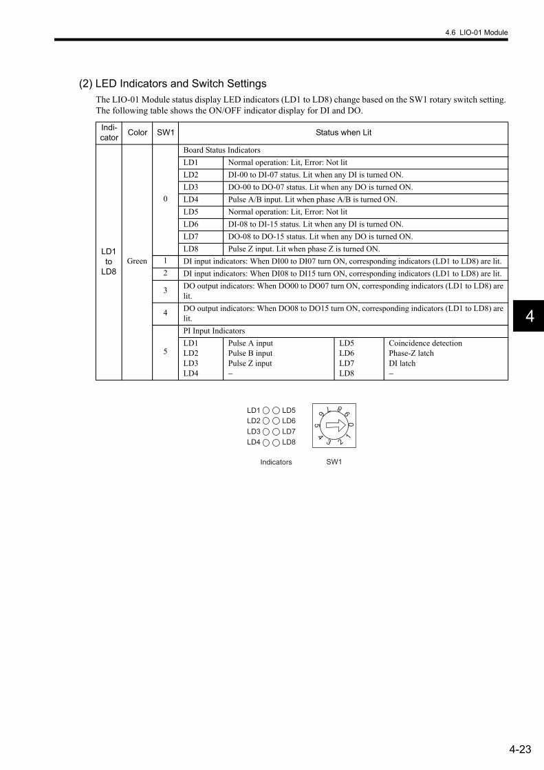
4.6 LIO-01 Module
4-23
4
(2) LED Indicators and Switch SettingsThe LIO-01 Module status display LED indicators (LD1 to LD8) change based on the SW1 rotary switch setting. The following table shows the ON/OFF indicator display for DI and DO.
Indi-cator Color SW1 Status when Lit
LD1 to
LD8Green
0
Board Status IndicatorsLD1 Normal operation: Lit, Error: Not litLD2 DI-00 to DI-07 status. Lit when any DI is turned ON.LD3 DO-00 to DO-07 status. Lit when any DO is turned ON.LD4 Pulse A/B input. Lit when phase A/B is turned ON.LD5 Normal operation: Lit, Error: Not litLD6 DI-08 to DI-15 status. Lit when any DI is turned ON.LD7 DO-08 to DO-15 status. Lit when any DO is turned ON.LD8 Pulse Z input. Lit when phase Z is turned ON.
1 DI input indicators: When DI00 to DI07 turn ON, corresponding indicators (LD1 to LD8) are lit.2 DI input indicators: When DI08 to DI15 turn ON, corresponding indicators (LD1 to LD8) are lit.
3 DO output indicators: When DO00 to DO07 turn ON, corresponding indicators (LD1 to LD8) are lit.
4 DO output indicators: When DO08 to DO15 turn ON, corresponding indicators (LD1 to LD8) are lit.
5
PI Input IndicatorsLD1LD2LD3LD4
Pulse A inputPulse B inputPulse Z input−
LD5LD6LD7LD8
Coincidence detectionPhase-Z latchDI latch−
LD3LD2LD1
LD4LD7LD6LD5
LD8
SW1
05
1
23
46 7 8
9
Indicators
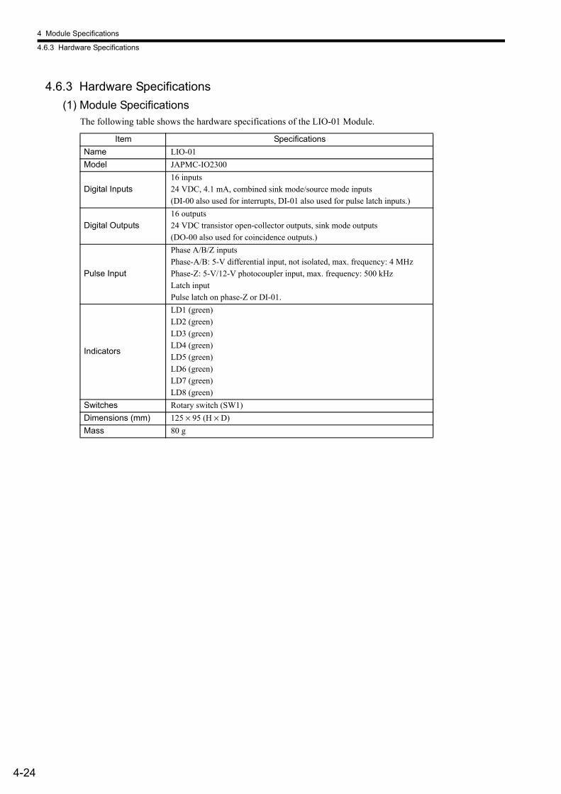
4 Module Specifications
4.6.3 Hardware Specifications
4-24
4.6.3 Hardware Specifications(1) Module Specifications
The following table shows the hardware specifications of the LIO-01 Module.
Item SpecificationsName LIO-01Model JAPMC-IO2300
Digital Inputs16 inputs24 VDC, 4.1 mA, combined sink mode/source mode inputs(DI-00 also used for interrupts, DI-01 also used for pulse latch inputs.)
Digital Outputs16 outputs24 VDC transistor open-collector outputs, sink mode outputs(DO-00 also used for coincidence outputs.)
Pulse Input
Phase A/B/Z inputsPhase-A/B: 5-V differential input, not isolated, max. frequency: 4 MHzPhase-Z: 5-V/12-V photocoupler input, max. frequency: 500 kHzLatch inputPulse latch on phase-Z or DI-01.
Indicators
LD1 (green)LD2 (green)LD3 (green)LD4 (green)LD5 (green)LD6 (green)LD7 (green)LD8 (green)
Switches Rotary switch (SW1)Dimensions (mm) 125 × 95 (H × D)Mass 80 g
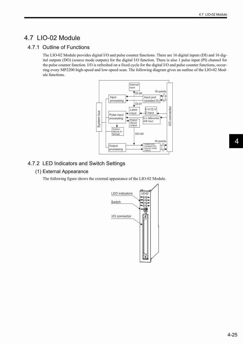
4.7 LIO-02 Module
4-25
4
4.7 LIO-02 Module4.7.1 Outline of Functions
The LIO-02 Module provides digital I/O and pulse counter functions. There are 16 digital inputs (DI) and 16 dig-ital outputs (DO) (source mode outputs) for the digital I/O function. There is also 1 pulse input (PI) channel forthe pulse counter function. I/O is refreshed on a fixed cycle for the digital I/O and pulse counter functions, occur-ring every MP2200 high-speed and low-speed scan. The following diagram gives an outline of the LIO-02 Mod-ule functions.
4.7.2 LED Indicators and Switch Settings(1) External Appearance
The following figure shows the external appearance of the LIO-02 Module.
DI-00
DI-01
DO-00
Output processing
Input processing
16 points
16 points
Syst
em b
us
I/O c
onne
ctor
Interrupt input
Input port (isolated DI)
Latch input Pulse input
processing
5-V/12-V Z input
5-V differential A/B input Coinci-
dence output
Coinci-dence in-terrupt
Output port (isolated DO) (source mode output)
LIO-02LED indicators
Switch
I/O connector
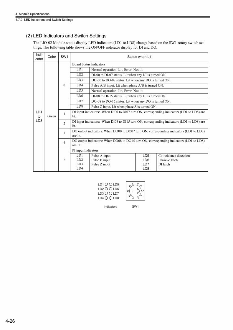
4 Module Specifications
4.7.2 LED Indicators and Switch Settings
4-26
(2) LED Indicators and Switch SettingsThe LIO-02 Module status display LED indicators (LD1 to LD8) change based on the SW1 rotary switch set-tings. The following table shows the ON/OFF indicator display for DI and DO.
Indi-cator Color SW1 Status when Lit
LD1 to
LD8Green
0
Board Status IndicatorsLD1 Normal operation: Lit, Error: Not litLD2 DI-00 to DI-07 status. Lit when any DI is turned ON.LD3 DO-00 to DO-07 status. Lit when any DO is turned ON.LD4 Pulse A/B input. Lit when phase A/B is turned ON.LD5 Normal operation: Lit, Error: Not litLD6 DI-08 to DI-15 status. Lit when any DI is turned ON.LD7 DO-08 to DO-15 status. Lit when any DO is turned ON.LD8 Pulse Z input. Lit when phase Z is turned ON.
1 DI input indicators: When DI00 to DI07 turn ON, corresponding indicators (LD1 to LD8) are lit.
2 DI input indicators: When DI08 to DI15 turn ON, corresponding indicators (LD1 to LD8) are lit.
3 DO output indicators: When DO00 to DO07 turn ON, corresponding indicators (LD1 to LD8) are lit.
4 DO output indicators: When DO08 to DO15 turn ON, corresponding indicators (LD1 to LD8) are lit.
5
PI input IndicatorsLD1LD2LD3LD4
Pulse A inputPulse B inputPulse Z input−
LD5LD6LD7LD8
Coincidence detectionPhase-Z latchDI latch−
LD3LD2LD1
LD4LD7LD6LD5
LD8
SW1
05
1
23
46 7 8
9
Indicators

4.7 LIO-02 Module
4-27
4
4.7.3 Hardware Specifications(1) Module Specifications
The following table shows the hardware specifications of the LIO-02 Module.
Item SpecificationsName LIO-02Model JAPMC-IO2301
Digital Inputs16 inputs24 VDC, 4.1 mA, combined sink mode/source mode inputs(DI-00 also used for interrupts, DI-01 also used for pulse latch inputs.)
Digital Outputs16 outputs24 VDC transistor open-collector outputs, source mode outputs(DO-00 also used for coincidence outputs.)
Pulse Input
Phase A/B/Z inputsPhase AB: 5-V differential input, not isolated, max. frequency: 4 MHzPhase-Z: 5-V/12-V photocoupler input, max. frequency: 500 kHzLatch inputPulse latch on phase-Z or DI-01.
Indicators
LD1 (green)LD2 (green)LD3 (green)LD4 (green)LD5 (green)LD6 (green)LD7 (green)LD8 (green)
Switches Rotary switch (SW1)Dimensions (mm) 125 × 95 (H × D)Mass 80 g
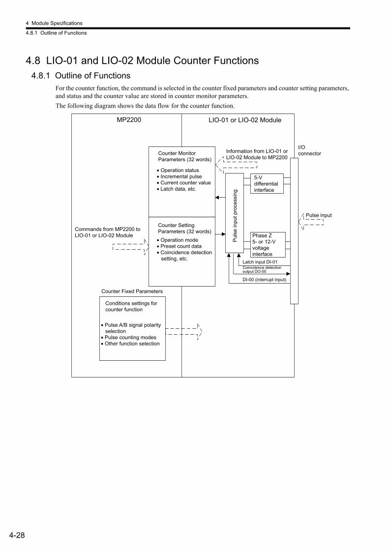
4 Module Specifications
4.8.1 Outline of Functions
4-28
4.8 LIO-01 and LIO-02 Module Counter Functions4.8.1 Outline of Functions
For the counter function, the command is selected in the counter fixed parameters and counter setting parameters, and status and the counter value are stored in counter monitor parameters.The following diagram shows the data flow for the counter function.
MP2200
Counter Fixed Parameters
LIO-01 or LIO-02 Module
Latch input DI-01 Coincidence detection output DO-00
Pulse input
Counter Setting Parameters (32 words)
Counter Monitor Parameters (32 words)
DI-00 (interrupt input)
Puls
e in
put p
roce
ssin
g Commands from MP2200 to LIO-01 or LIO-02 Module
Conditions settings for counter function
Information from LIO-01 or LIO-02 Module to MP2200
I/O connector
5-V differential interface
Phase Z 5- or 12-V voltage interface
• Operation status• Incremental pulse• Current counter value• Latch data, etc.
• Operation mode• Preset count data• Coincidence detection
setting, etc.
• Pulse A/B signal polarity selection
• Pulse counting modes• Other function selection
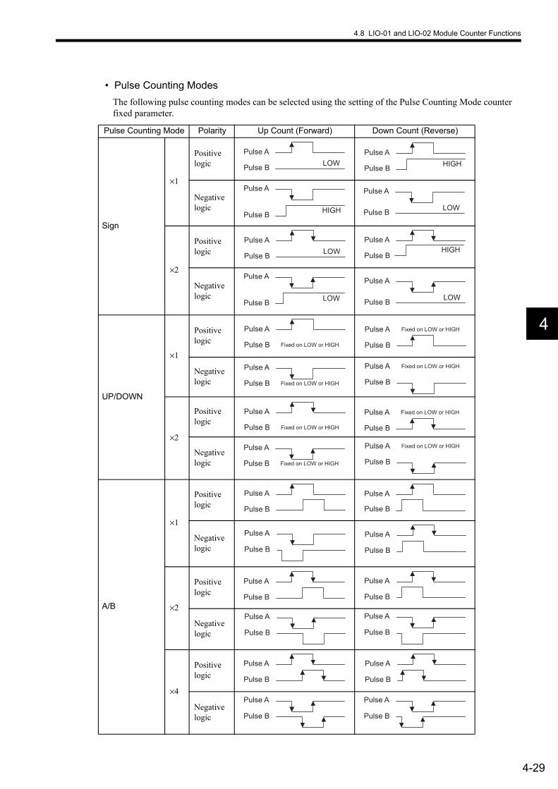
4.8 LIO-01 and LIO-02 Module Counter Functions
4-29
4
• Pulse Counting ModesThe following pulse counting modes can be selected using the setting of the Pulse Counting Mode counter fixed parameter.
Pulse Counting Mode Polarity Up Count (Forward) Down Count (Reverse)
Sign
×1
Positive logic
Negative logic
×2
Positive logic
Negative logic
UP/DOWN
×1
Positive logic
Negative logic
×2
Positive logic
Negative logic
A/B
×1
Positive logic
Negative logic
×2
Positive logic
Negative logic
×4
Positive logic
Negative logic
LOWPulse A
Pulse B HIGHPulse A
Pulse B
HIGH
Pulse A
Pulse BLOW
Pulse A
Pulse B
LOWPulse A
Pulse BHIGH
Pulse A
Pulse B
LOW
Pulse A
Pulse BLOW
Pulse A
Pulse B
Pulse A
Pulse B Fixed on LOW or HIGH
Pulse A
Pulse B
Fixed on LOW or HIGH
Pulse A
Pulse B Fixed on LOW or HIGH
Pulse A
Pulse B
Fixed on LOW or HIGH
Pulse A
Pulse B Fixed on LOW or HIGH
Pulse A
Pulse B
Fixed on LOW or HIGH
Pulse A
Pulse B Fixed on LOW or HIGH
Pulse A
Pulse B
Fixed on LOW or HIGH
Pulse A
Pulse B
Pulse A
Pulse B
Pulse A
Pulse B
Pulse A
Pulse B
Pulse A
Pulse B
Pulse A
Pulse B
Pulse A
Pulse B
Pulse A
Pulse B
Pulse A
Pulse B
Pulse A
Pulse B
Pulse A
Pulse B
Pulse A
Pulse B

4 Module Specifications
4.8.2 Counter Function Details
4-30
4.8.2 Counter Function Details(1) Pulse Count Function
The count is incremented and decremented based on the pulse A and pulse B inputs.The following functions are supported when specified in the counter setting parameter.
• Count prohibit: Prohibits counting.• Count preset: Forces the counter value to change.• PI latch detection: Saves the counter value when an external signal is input.• Coincidence detection: Outputs an external output signal when the counter setting parameter Coincidence
Detection setting and the counter current value match.
* 1. Current count value = Hardware counter (IL +4)* 2. Count preset = Count preset data (OL +2)Note: : Counter fixed parameter No. 1: Leading Register Number
n1 n2 n3 n4 n5 n6 n7
n1
n2
n3
n4 n5
n6
n7
MIN(80000000H)
MIN(80000000H)
UP UP DOWN UP DOWN DOWN
Ts
0
(+)
(−)
MAX (7FFFFFFFH) MAX (7FFFFFFFH)
Stop Stop Stop
Current count value*1
A or B pulse
Count preset*2
Ts: Scan setting
Count preset*2
Cou
nter
cou
ntin
g re
gist
er

4.8 LIO-01 and LIO-02 Module Counter Functions
4-31
4
(2) Coincidence Output and Coincidence Interrupt FunctionsThe Coincidence Output and Coincidence Interrupt Functions output an external output signal (coincidence detection signal) and output an interrupt signal to the MP2200 when the current counter value and a preset counter setting parameter (Coincidence Detection Setting: OL +4) match.The Coincidence Output Function is enabled when 1 is set to the counter fixed parameter No. 9 (Coincidence Detection Function Selection).The Coincidence Interrupt Function is enabled when 1 is set to the counter fixed parameter No. 10 (Coincidence Interrupt Function Selection).
* 1. Coincidence point detection value = Coincidence detection setting (OL +4)* 2. Coincidence detection request = Command setting (OW + 0 Bit 3)* 3. T0: Max. time from when interrupt request signal received by MP2200 until interrupt processing starts
(70 to 120 ms).* 4. TI: Time from when interrupt request signal is received until DWG.I (interrupt process drawing) execu-
tion starts.
• Coincidence output signal uses DO-00. Therefore, DO-00 will be masked when 1 is set to fixed parameter No. 9 (Coincidence Detection Function Selection). Actual signal outputs are not affected even if the register allocated to DO-00 is turned ON or OFF from the ladder program.
• Use counter status (IW + 0 Bit5) to monitor coincidence detection signal outputs.
Normal program execution: Approx. 90 to 170 msI/O command executed directly: Approx. 90 to (1,460 + 40 + N) ms
N = No. of direct I/O words (Max. 8)
COINDAT
COINDATA
T0 3
T1 4
0
(+)
(−)
Interrupt reception
Interrupt request signal
Coincidence output signal
Coincidence detection request*2
Coincidence point detection*1
Cou
nter
cou
ntin
g re
gist
er
IMPORTANT
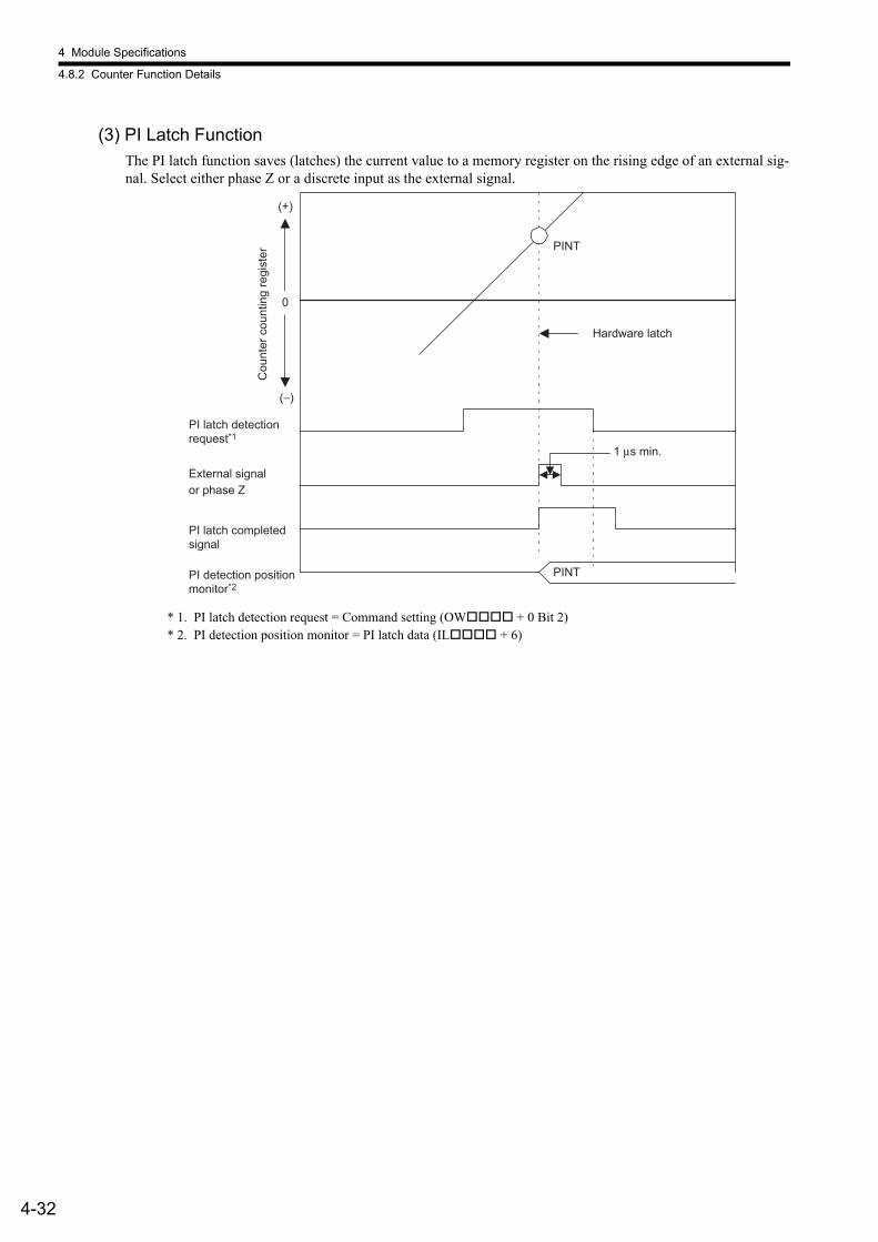
4 Module Specifications
4.8.2 Counter Function Details
4-32
(3) PI Latch FunctionThe PI latch function saves (latches) the current value to a memory register on the rising edge of an external sig-nal. Select either phase Z or a discrete input as the external signal.
* 1. PI latch detection request = Command setting (OW + 0 Bit 2)* 2. PI detection position monitor = PI latch data (IL + 6)
PINT
0
(+)
(−)
PINTPI detection position monitor*2
PI latch completed signal
External signal
PI latch detection request*1
1 µs min.
Hardware latch
or phase Z
Cou
nter
cou
ntin
g re
gist
er

4.8 LIO-01 and LIO-02 Module Counter Functions
4-33
4
4.8.3 Electronic Gear FunctionThe Electronic Gear Function can be used when counter fixed parameter No. 15 (Reference Unit Selection) is set to any value except 0.
(1) OutlineThe Electronic Gear Function is used to set the workpiece travel distance per pulse input to the LIO Module counter to any value.
(2) SettingsUse steps 1 to 5 in the following procedure to make the settings.
1. Confirm the machine specifications.
2. Confirm the number of encoder pulses input to the counter and set this value to the counter fixed parame-ter No. 24 (Number of Pulses Per Encoder Rotation).
3. Decide the reference unit.The reference unit is the smallest unit for the position data that moves the load. (The smallest reference unit used by the host device.)
• When reference unit is 0.01 mm, 0.001 mm, 0.1°, or 0.01 inches:The workpiece is moved 1 reference unit per pulse reference input.
• When reference unit is 1 µm:When 50,000 reference pulses are input, the workpiece will be moved by 50,000 × 1 µm = 50 mm.
Without Electronic Gear With Electronic Gear
1 µ
10 mm
Ball screw pitch: 6 mm
Workpiece
Encoder pulse: 2048
Encoder pulse: 2048 Ball screw pitch: 6 mm
Workpiece Reference unit: 1 µm
To move the workpiece 10 mm,
= 10000 reference units
The machine conditions and reference unit are defined beforehand by the Electronic Gear.
To move the workpiece 10 mm, with a reference unit of 1 µm, 6 mm per rotation, therefore
10 ÷ 6 = 1.6666 rotations2,048 × 4 pulses per rotation, therefore1.6666 × 2,048 × 4 = 13,653 pulses.13,653 pulses are input as the reference.This conversion must be made on the host device.
Elements relating to the Electronic Gear• Gear ratio• Ball screw pitch• Pulley diameter, etc.
Ball screw pitch
Gear ratio
Reference unit: 0.001 mm
Moving a table in 0.001-mm increments.
Take the machine specifications, positioning accuracy, and other factors into account when deciding the reference unit.
EXAMPLE

4 Module Specifications
4.8.3 Electronic Gear Function
4-34
4. Find the load travel distance for each rotation of the load axis using the reference unit.
• For a ball screw pitch of 5 mm and a reference unit of 0.001 mm:
5. Set the Encoder Gear Ratio and the Machine Gear Ratio in the counter fixed parameters No. 20 and No. 21.
• No. 18 setting range: 1 to 231-1 [1 = 1 reference unit]
Setting Examples• Load moving amount per load axis rotation = 12 mm• Smallest reference unit = 0.001 mm (reference unit: mm, to 3 decimal places)
Counter fixed parameter No. 18 = 12 mm/0.001 mm = 12000• When the encoder axis has rotated m times and the mechanical configuration allows the load axis to
rotate n times, set the following values:Counter fixed parameter No. 20 = m rotationsCounter fixed parameter No. 21 = n rotations Setting range: 1 to 65,535 [rotations]
• For the configuration shown in the diagram:
Gear ratio = n/m = (3/7) × (4/9) = 4/21Therefore, set the following values: Counter fixed parameter No. 20 = 21
Counter fixed parameter No. 21 = 4
Ball screw Round table Belt + pulley
Reference unit Travel distance when load axis rotated once (reference unit) = Travel distance when load axis rotated once
EXAMPLE
0.001 = 5000 (Reference unit)5
P
PLoad axis
1 rotation = Reference unit
P: pitch 360
Load axis 1 rotation =
Reference unit
D
πD
πD
Load axis
D: Pulley diameter
1 rotation = Reference unit
EXAMPLE
7 rotations
3 rotations 9 rotations
4 rotations
Load axis n rotations Encoder axis m rotations

4.8 LIO-01 and LIO-02 Module Counter Functions
4-35
4
(3) Setting ExampleThe following are parameter setting examples for each kind of load mechanical configuration.
(a) Ball Screws
In the above machine system, if the requirement is reference unit = output unit = 0.001 mm, the setting of each parameter will be as follows:• No. 18 = 6 mm/0.001 mm = 6000• Gear ratio = n/m = 5/7• No. 20 = 7• No. 21 = 5
(b) Rotating Loads
In the above machine system, if the requirement is reference unit = output unit = 0.1°, the setting of each parameter will be as follows:• No. 18 = 360°/0.1° = 3600• Gear ratio = n/m = 10/30 = 1/3• No. 20 = 3• No. 21 = 1
m
n
7 rotations
5 rotations
Encoder
Ball screw pitch P = 6 mm/rotation
m
n
10 rotations
30 rotations Encoder
Rotating load 360°/rotation
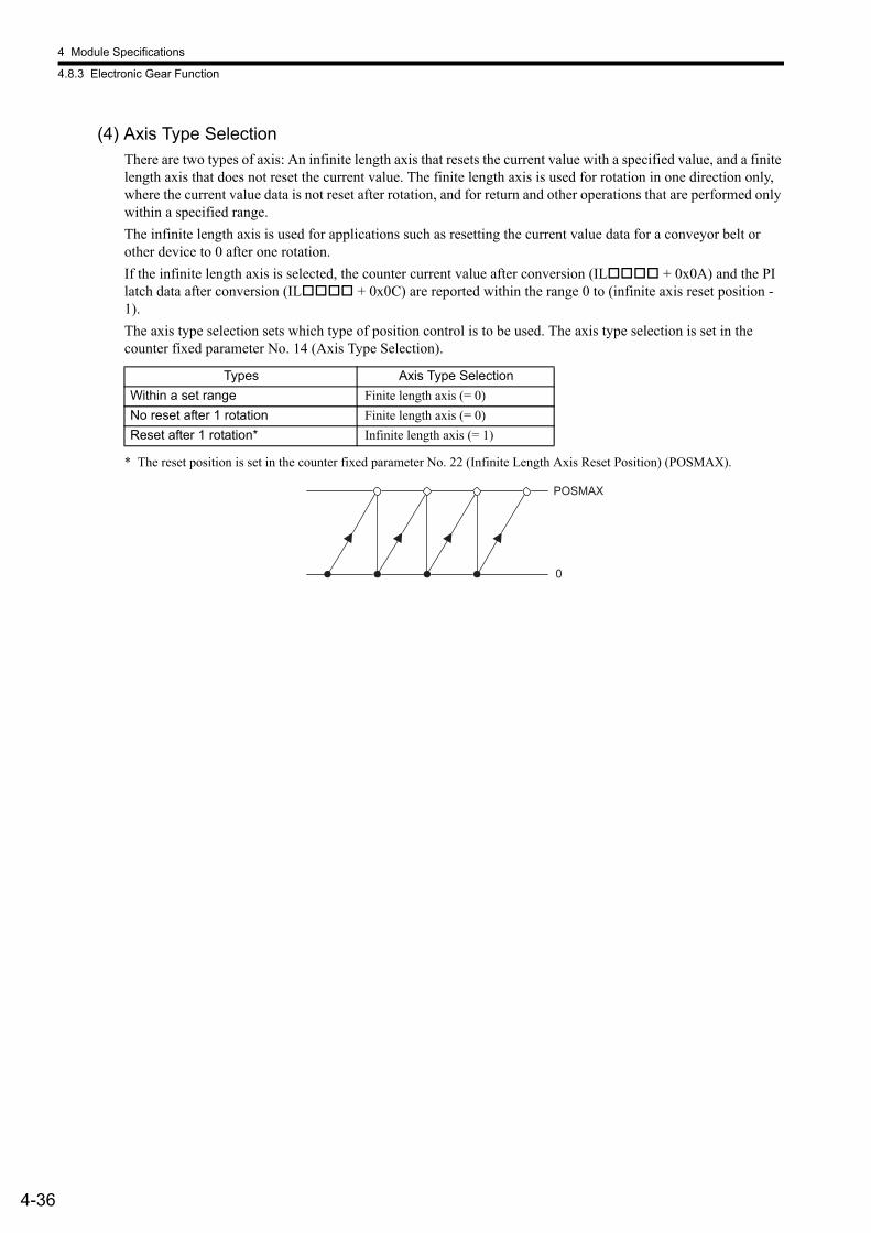
4 Module Specifications
4.8.3 Electronic Gear Function
4-36
(4) Axis Type SelectionThere are two types of axis: An infinite length axis that resets the current value with a specified value, and a finite length axis that does not reset the current value. The finite length axis is used for rotation in one direction only, where the current value data is not reset after rotation, and for return and other operations that are performed only within a specified range.The infinite length axis is used for applications such as resetting the current value data for a conveyor belt or other device to 0 after one rotation.If the infinite length axis is selected, the counter current value after conversion (IL + 0x0A) and the PI latch data after conversion (IL + 0x0C) are reported within the range 0 to (infinite axis reset position - 1).The axis type selection sets which type of position control is to be used. The axis type selection is set in the counter fixed parameter No. 14 (Axis Type Selection).
* The reset position is set in the counter fixed parameter No. 22 (Infinite Length Axis Reset Position) (POSMAX).
Types Axis Type SelectionWithin a set range Finite length axis (= 0)No reset after 1 rotation Finite length axis (= 0)Reset after 1 rotation* Infinite length axis (= 1)
POSMAX
0
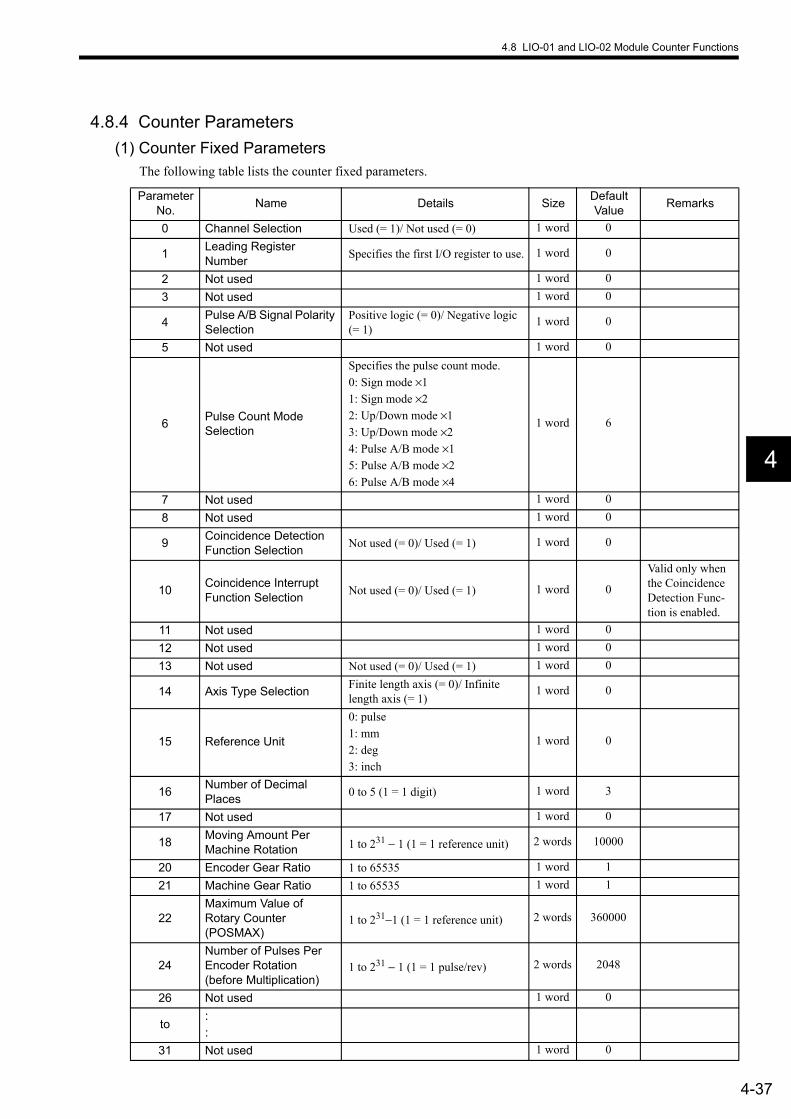
4.8 LIO-01 and LIO-02 Module Counter Functions
4-37
4
4.8.4 Counter Parameters(1) Counter Fixed Parameters
The following table lists the counter fixed parameters.
Parameter No. Name Details Size Default
Value Remarks
0 Channel Selection Used (= 1)/ Not used (= 0) 1 word 0
1 Leading Register Number Specifies the first I/O register to use. 1 word 0
2 Not used 1 word 03 Not used 1 word 0
4 Pulse A/B Signal Polarity Selection
Positive logic (= 0)/ Negative logic (= 1)
1 word 0
5 Not used 1 word 0
6 Pulse Count Mode Selection
Specifies the pulse count mode.0: Sign mode ×11: Sign mode ×22: Up/Down mode ×13: Up/Down mode ×24: Pulse A/B mode ×15: Pulse A/B mode ×26: Pulse A/B mode ×4
1 word 6
7 Not used 1 word 08 Not used 1 word 0
9 Coincidence Detection Function Selection Not used (= 0)/ Used (= 1) 1 word 0
10 Coincidence Interrupt Function Selection Not used (= 0)/ Used (= 1) 1 word 0
Valid only when the Coincidence Detection Func-tion is enabled.
11 Not used 1 word 012 Not used 1 word 013 Not used Not used (= 0)/ Used (= 1) 1 word 0
14 Axis Type Selection Finite length axis (= 0)/ Infinite length axis (= 1)
1 word 0
15 Reference Unit
0: pulse1: mm2: deg3: inch
1 word 0
16 Number of Decimal Places 0 to 5 (1 = 1 digit) 1 word 3
17 Not used 1 word 0
18 Moving Amount Per Machine Rotation 1 to 231 − 1 (1 = 1 reference unit) 2 words 10000
20 Encoder Gear Ratio 1 to 65535 1 word 121 Machine Gear Ratio 1 to 65535 1 word 1
22Maximum Value of Rotary Counter (POSMAX)
1 to 231−1 (1 = 1 reference unit) 2 words 360000
24Number of Pulses Per Encoder Rotation (before Multiplication)
1 to 231 − 1 (1 = 1 pulse/rev) 2 words 2048
26 Not used 1 word 0
to::
31 Not used 1 word 0
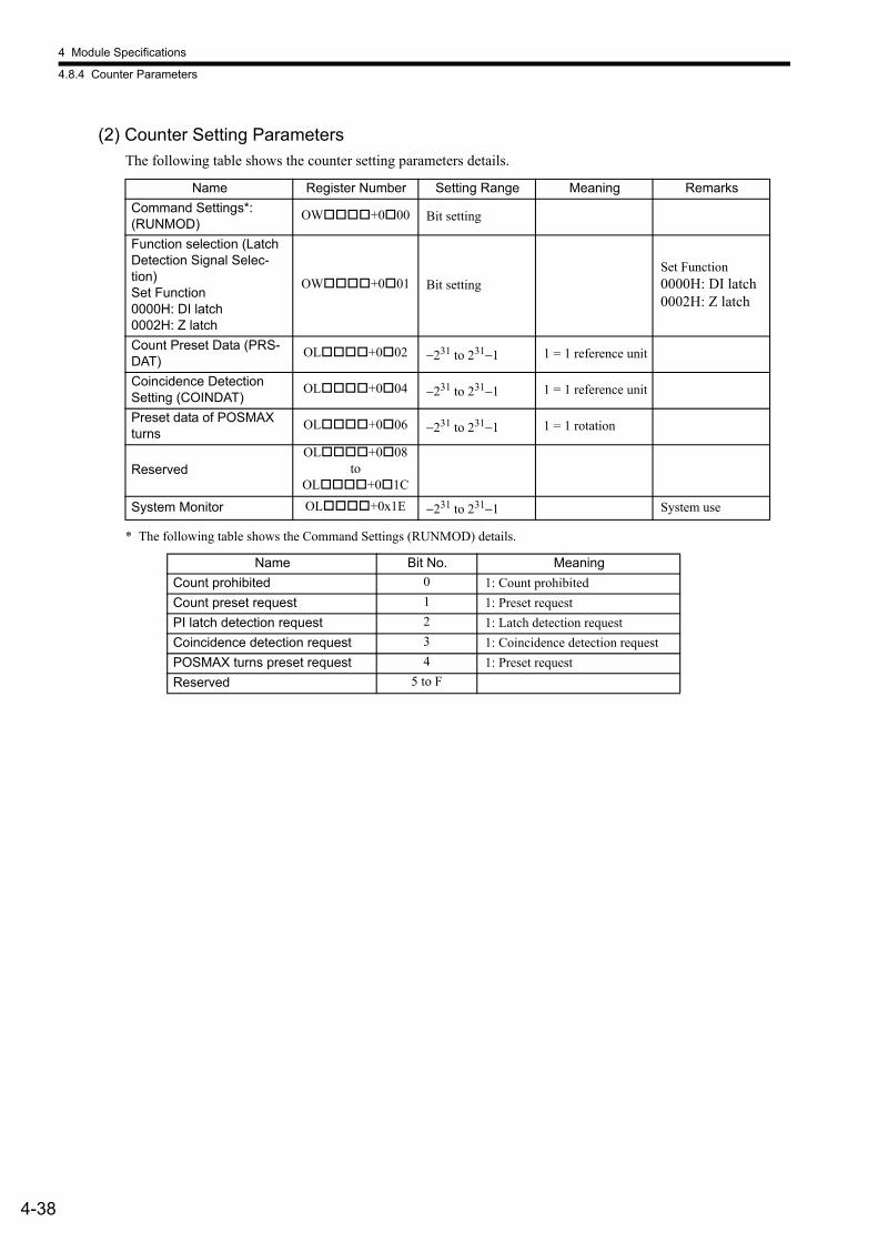
4 Module Specifications
4.8.4 Counter Parameters
4-38
(2) Counter Setting ParametersThe following table shows the counter setting parameters details.
* The following table shows the Command Settings (RUNMOD) details.
Name Register Number Setting Range Meaning RemarksCommand Settings*: (RUNMOD)
OW +0 00 Bit setting
Function selection (Latch Detection Signal Selec-tion)Set Function0000H: DI latch0002H: Z latch
OW +0 01 Bit settingSet Function0000H: DI latch0002H: Z latch
Count Preset Data (PRS-DAT)
OL +0 02 −231 to 231−1 1 = 1 reference unit
Coincidence Detection Setting (COINDAT)
OL +0 04 −231 to 231−1 1 = 1 reference unit
Preset data of POSMAX turns
OL +0 06 −231 to 231−1 1 = 1 rotation
ReservedOL +0 08
to OL +0 1C
System Monitor OL +0x1E −231 to 231−1 System use
Name Bit No. MeaningCount prohibited 0 1: Count prohibitedCount preset request 1 1: Preset requestPI latch detection request 2 1: Latch detection requestCoincidence detection request 3 1: Coincidence detection requestPOSMAX turns preset request 4 1: Preset requestReserved 5 to F

4.8 LIO-01 and LIO-02 Module Counter Functions
4-39
4
(3) Counter Monitor ParametersThe following table shows counter monitor parameters details.
* Calculation: A moving average of the processing results for 32 scans.• Without Electronic Gear
Feedback Speed (pulse/s) = (No. of incremental pulses × 1000)/Ts• With Electronic Gear
Feedback Speed (reference unit/s) = (No. of incremental pulses after conversion × 1000)/TsTS: Scan time (ms) for counter synchronized scan.
The following table shows Status (RUNSTS) details.
Name Register Number Range Meaning RemarksStatus (RUNSTS) IW +0 00 Bit settingsReserved IW +0 01Number of Incremental Pulses (PDV)
IL +0 02 −231 to 231−1 1 = 1 pulse
Current Counter Value (PFB)
IL +0 04 −231 to 231−1 1 = 1 pulse
PI Latch Data (FREQ) IL +0 06 −231 to 231−1 1 = 1 pulseNumber of Incremental Pulses after Conversion (PDVG)
IL +0 08 −231 to 231−1 1 = 1 reference unitSame as number of incre-mental pulses when Elec-tronic Gear not used.
Current Counter Value after Conversion (PFBG)
IL +0 0A −231 to 231−1 1 = 1 reference unitSame as current counter value when Electronic Gear not used.
PI Latch Data after Con-version (FREQG)
IL +0 0C −231 to 231−1 1 = 1 reference unit Same as PI latch data when Electronic Gear not used.
POSMAX Turn Number IL +0 0E −231 to 231−1 1 = 1 rotation
Feedback Speed* IL +0 10 −231 to 231−1 1 = reference unit/s When Electronic Gear not used: 1 = 1 pulse/s
ReservedIL +0 12
to IL +0 1C
System monitor IL +0 1E −231 to 231−1 System use
Name Bit No. Meaning RemarksData Setting Error 0 1: Data setting error
Fixed Parameter Setting Error 1 1: Fixed parameter setting error ON until normal write completed.
Count Value Preset Completed 2 1: Count value preset completedPI Latch Completed Signal 3 1: PI latch completedPulse-A/B 0 4 1: Feedback pulse is ±1 or lessCoincidence Detection Signal 5 1: Coincidence detection ON Detected in pulse units.Pulse-A Status Display 6 1: HighPulse-B Status Display 7 1: HighReserved 8Writing Fixed Parameter 9 1: Writing parameter online ON only during writingPhase-A or -B Disconnect Alarm AReserved BPOSMAX Turns Preset Completed C 1: CompletedReserved DReserved E
Module Ready F 1: Counter processing being exe-cuted
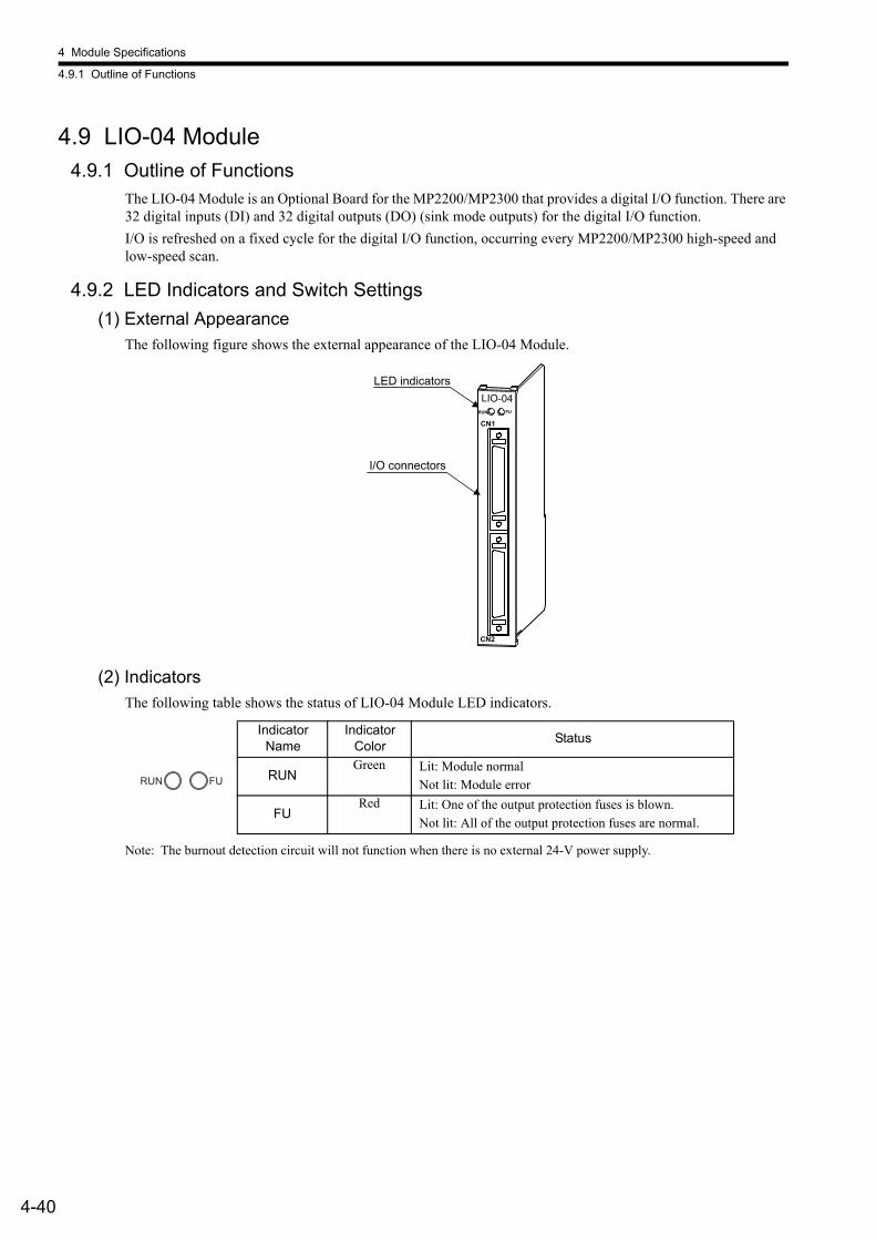
4 Module Specifications
4.9.1 Outline of Functions
4-40
4.9 LIO-04 Module4.9.1 Outline of Functions
The LIO-04 Module is an Optional Board for the MP2200/MP2300 that provides a digital I/O function. There are 32 digital inputs (DI) and 32 digital outputs (DO) (sink mode outputs) for the digital I/O function. I/O is refreshed on a fixed cycle for the digital I/O function, occurring every MP2200/MP2300 high-speed and low-speed scan.
4.9.2 LED Indicators and Switch Settings(1) External Appearance
The following figure shows the external appearance of the LIO-04 Module.
(2) IndicatorsThe following table shows the status of LIO-04 Module LED indicators.
Note: The burnout detection circuit will not function when there is no external 24-V power supply.
LED indicators
I/O connectors
LIO-04RUN FU
CN2
CN1
Indicator Name
Indicator Color Status
RUNGreen Lit: Module normal
Not lit: Module error
FURed Lit: One of the output protection fuses is blown.
Not lit: All of the output protection fuses are normal.
FURUN

4.9 LIO-04 Module
4-41
4
4.9.3 Hardware Specifications(1) Module Specifications
The following table shows the hardware specifications of the LIO-04 Module.
* Number of ON Inputs vs Ambient Temperature Characteristic
Item SpecificationsName LIO-04Model JAPMC-IO2303
Digital Inputs
32 inputs24 VDC, 4.1 mA, combined sink mode/source mode inputs(DI-00, 01, 16, and 17 also used for interrupts.)Simultaneously ON Inputs16 points (8 inputs/common): At ambient temperature of 55°C and 24 VDC10 points (5 inputs/common): At ambient temperature of 55°C and 28.8 VDCRefer to the following characteristics graph for details.
Digital Outputs32 outputs24 VDC transistor open-collector outputs, sink mode outputs
IndicatorsRUN (green)ERR (red)
Dimensions (mm) 125 × 95 (H × D)Mass 80 g
Points (32 inputs, 28°C) (32 inputs, 41°C)
Input voltage: 24 VDC
Input voltage: 28.8 VDC
(16 inputs, 55°C)
(10 inputs, 55°C)
Ambient temperature
30
35
No.
of O
N in
puts
(°C)40 50 600 10 20 30
5
10
15
20
0
25
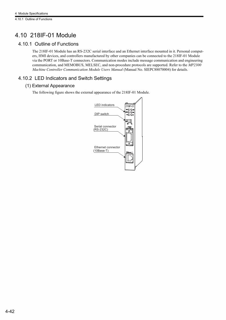
4 Module Specifications
4.10.1 Outline of Functions
4-42
4.10 218IF-01 Module4.10.1 Outline of Functions
The 218IF-01 Module has an RS-232C serial interface and an Ethernet interface mounted in it. Personal comput-ers, HMI devices, and controllers manufactured by other companies can be connected to the 218IF-01 Module via the PORT or 10Base-T connectors. Communication modes include message communication and engineering communication, and MEMOBUS, MELSEC, and non-procedure protocols are supported. Refer to the MP2300 Machine Controller Communication Module Users Manual (Manual No. SIEPC88070004) for details.
4.10.2 LED Indicators and Switch Settings(1) External Appearance
The following figure shows the external appearance of the 218IF-01 Module.
(10Base-T)
(RS-232C)
218IF-01LED indicators
DIP switch
Serial connector
Ethernet connector
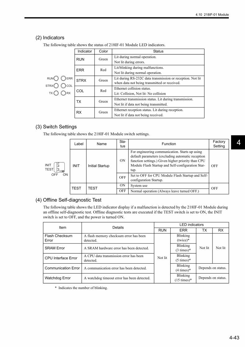
4.10 218IF-01 Module
4-43
4
(2) IndicatorsThe following table shows the status of 218IF-01 Module LED indicators.
(3) Switch SettingsThe following table shows the 218IF-01 Module switch settings.
(4) Offline Self-diagnostic TestThe following table shows the LED indicator display if a malfunction is detected by the 218IF-01 Module during an offline self-diagnostic test. Offline diagnostic tests are executed if the TEST switch is set to ON, the INIT switch is set to OFF, and the power is turned ON.
* Indicates the number of blinking.
Indicator Color Status
RUN Green Lit during normal operation.Not lit during errors.
ERR Red Lit/blinking during malfunctions.Not lit during normal operation.
STRX Green Lit during RS-232C data transmission or reception. Not lit when data not being transmitted or received.
COL Red Ethernet collision status.Lit: Collision, Not lit: No collision
TX Green Ethernet transmission status. Lit during transmission.Not lit if data not being transmitted.
RX Green Ethernet reception status. Lit during reception.Not lit if data not being received.
ERR
COL
RX
RUN
STRX
TX
Label Name Sta-tus Function Factory
Setting
INIT Initial StartupON
For engineering communication. Starts up using default parameters (excluding automatic reception function settings.) Given higher priority than CPU Module Flash Startup and Self-configuration Star-tup.
OFF
OFF Set to OFF for CPU Module Flash Startup and Self-configuration Startup.
TEST TESTON System use
OFFOFF Normal operation (Always leave turned OFF.)
INITTEST
ONOFF
Item DetailsLED indicators
RUN ERR TX RXFlash Checksum Error
A flash memory checksum error has been detected.
Not lit
Blinking (twice)*
Not lit Not litSRAM Error A SRAM hardware error has been detected.Blinking
(3 times)*
CPU Interface Error A CPU data transmission error has been detected.
Blinking (5 times)*
Communication Error A communication error has been detected.Blinking
(4 times)* Depends on status.
Watchdog Error A watchdog timeout error has been detected.Blinking
(15 times)* Depends on status.
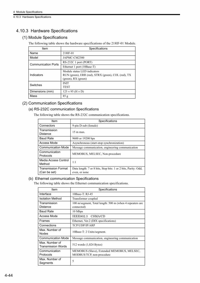
4 Module Specifications
4.10.3 Hardware Specifications
4-44
4.10.3 Hardware Specifications(1) Module Specifications
The following table shows the hardware specifications of the 218IF-01 Module.
(2) Communication Specifications(a) RS-232C communication Specifications
The following table shows the RS-232C communication specifications.
(b) Ethernet communication SpecificationsThe following table shows the Ethernet communication specifications.
Item SpecificationsName 218IF-01Model JAPMC-CM2300
Communication PortsRS-232C 1 port (PORT)Ethernet 1 port (10Base-T)
IndicatorsModule status LED indicatorsRUN (green), ERR (red), STRX (green), COL (red), TX (green), RX (green)
Switches INITTEST
Dimensions (mm) 125 × 95 (H × D)Mass 85 g
Item SpecificationsConnectors 9-pin D-sub (female)Transmission Distance 15 m max.
Baud Rate 9600 or 19200 bps Access Mode Asynchronous (start-stop synchronization)Communication Mode Message communication, engineering communicationCommunication Protocols MEMOBUS, MELSEC, Non-procedure
Media Access Control Method 1:1
Transmission Format (Can be set)
Data length: 7 or 8 bits, Stop bits: 1 or 2 bits, Parity: Odd, even, or none
Item SpecificationsInterface 10Base-T: RJ-45Isolation Method Transformer coupledTransmission Distance
100 m/segment, Total length: 500 m (when 4 repeaters are connected)
Baud Rate 10 MbpsAccess Mode IEEE802.3 CSMA/CDFrames Ethernet, Ver.2 (DIX specifications)Connections TCP/UDP/IP/ARPMax. Number of Nodes 10Base-T: 2 Units/segment.
Communication Mode Message communication, engineering communicationMax. Number of Transmission Words 512 words (1,024 Bytes)
Communication Protocols
MEMOBUS (Slave), Extended MEMOBUS, MELSEC, MODBUS/TCP, non-procedure
Max. Number of Segments 5
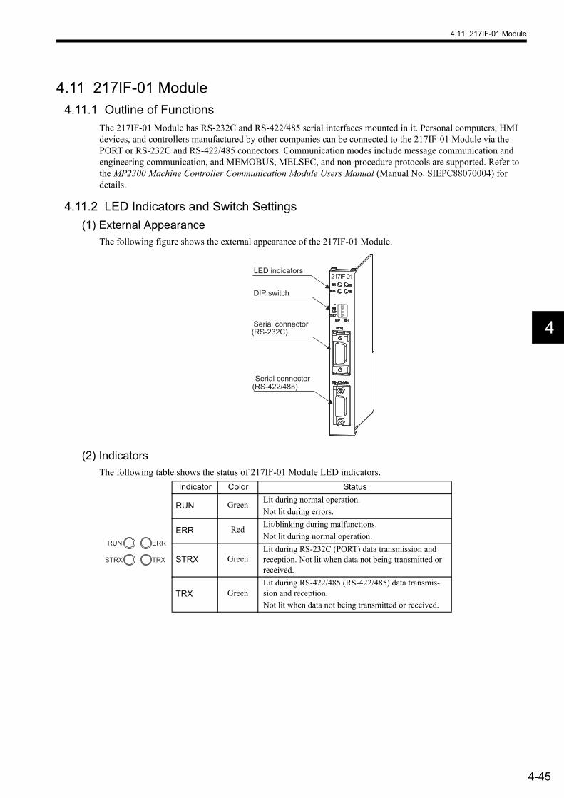
4.11 217IF-01 Module
4-45
4
4.11 217IF-01 Module4.11.1 Outline of Functions
The 217IF-01 Module has RS-232C and RS-422/485 serial interfaces mounted in it. Personal computers, HMI devices, and controllers manufactured by other companies can be connected to the 217IF-01 Module via the PORT or RS-232C and RS-422/485 connectors. Communication modes include message communication and engineering communication, and MEMOBUS, MELSEC, and non-procedure protocols are supported. Refer to the MP2300 Machine Controller Communication Module Users Manual (Manual No. SIEPC88070004) for details.
4.11.2 LED Indicators and Switch Settings(1) External Appearance
The following figure shows the external appearance of the 217IF-01 Module.
(2) IndicatorsThe following table shows the status of 217IF-01 Module LED indicators.
(RS-232C)
(RS-422/485)
217IF-01LED indicators
DIP switch
Serial connector
Serial connector
Indicator Color Status
RUN Green Lit during normal operation.Not lit during errors.
ERR Red Lit/blinking during malfunctions.Not lit during normal operation.
STRX GreenLit during RS-232C (PORT) data transmission and reception. Not lit when data not being transmitted or received.
TRX GreenLit during RS-422/485 (RS-422/485) data transmis-sion and reception.Not lit when data not being transmitted or received.
ERR
TRXSTRX
RUN

4 Module Specifications
4.11.2 LED Indicators and Switch Settings
4-46
(3) Switch SettingsThe following table shows the 217IF-01 Module switch settings.
(4) Offline Self-diagnostic TestThe following table shows the LED indicator display if a malfunction is detected by the 217IF-01 Module during an offline self-diagnostic test. Offline diagnostic tests are executed if the TEST switch is set to ON, the INIT switch is set to OFF, and the power is turned ON.
* Indicates the number of blinking.
Label Name Sta-tus Function Factory
Setting− Reserved − Always leave set to OFF. OFF
485 485 ModeON Uses the RS422/485 port as an RS-485.
OFFOFF Uses the RS422/485 port as an RS-422.
INIT Initial startupON
For engineering communication. Starts up RS-232C(PORT) using default parameters (excluding auto-matic reception function settings.) The RS-422/485port is disabled. Given higher priority than CPUModule Flash Startup and Self-configuration Star-tup.
OFF
OFF Set to OFF for CPU Module Flash Startup and Self-configuration Startup.
TEST TESTON System use.
OFFOFF Normal operation (Always leave turned OFF.)
TESTINIT485
ONOFF
Item DetailsLED Indicators
RUN ERR STRX1/STRX2 RX
Flash Checksum Error
A flash memory checksum error has been detected.
Not lit
Blinking (once)*
Not litDepends on sta-
tus.
SRAM Error A SRAM hardware error has been detected.Blinking (twice)*
DPRAM Error A DPRAM hardware error has been detected.Blinking
(3 times)*
Communication Error A communication error has been detected.Blinking
(4 times)*
RS-232C Error An RS-232C loopback error has been detected.
Blinking (5 times)*
Watchdog Error A watchdog timeout error has been detected.Blinking
(15 times)*

4.11 217IF-01 Module
4-47
4
4.11.3 Hardware Specifications(1) Module Specifications
The following table shows the hardware specifications of the 217IF-01 Module.
(2) Communication Specifications(a) RS-232C communication Specifications
The following table shows the RS-232C communication specifications.
Note: The baud rate depends on the connected devices.
(b) RS-422/485 Communication SpecificationsThe following table shows RS-422/485 communication specifications.
Item SpecificationsName 217IF-01Model JAPMC-CM2310
Communication PortsRS-232C 1 port (PORT)RS-422/485 1 port (RS422/485)
IndicatorsModule status LED indicators, RUN (green), ERR (red), STRX (green), TRX (green)
Setting Switches
−−−485INITTEST
Dimensions (mm) 125 × 95 (H × D)Mass 90 g
Item SpecificationsInterface 1 port (PORT)Connectors 9-pin D-sub (female)Transmission Distance 15 m max.Baud Rate 9.6, 14.4, 19.2, 28.8, 38.4, 48.0, 57.6, or 76.8 kbpsAccess Mode Asynchronous (start-stop synchronization)Communication Mode Message communication, engineering communicationCommunication Protocols MEMOBUS, MELSEC, OMRON, and non-procedureMedia Access Control Method 1:1
Transmission Format (Can be set)
Data length: 7 or 8 bitsStop bits: 1 or 2 bitsParity: Odd, even, or none
Item SpecificationsInterface 1 port (RS422/485)Connectors MDR14 pin (female)Transmission Distance 300 m max.Baud Rate 9.6, 14.4, 19.2, 28.8, 38.4, 48.0, 57.6, or 76.8 kbpsSynchronization Mode Asynchronous (start-stop synchronization)Communication Protocols MEMOBUS, MELSEC, non-procedureMedia Access Control Method
1:1 (RS-422)1:N (RS-485)
Transmission Format (Can be set)
Data length: 7 or 8 bitsStop bits: 1 or 2 bitsParity: Odd, even, or none
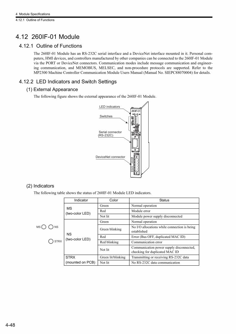
4 Module Specifications
4.12.1 Outline of Functions
4-48
4.12 260IF-01 Module4.12.1 Outline of Functions
The 260IF-01 Module has an RS-232C serial interface and a DeviceNet interface mounted in it. Personal com-puters, HMI devices, and controllers manufactured by other companies can be connected to the 260IF-01 Modulevia the PORT or DeviceNet connectors. Communication modes include message communication and engineer-ing communication, and MEMOBUS, MELSEC, and non-procedure protocols are supported. Refer to theMP2300 Machine Controller Communication Module Users Manual (Manual No. SIEPC88070004) for details.
4.12.2 LED Indicators and Switch Settings(1) External Appearance
The following figure shows the external appearance of the 260IF-01 Module.
(2) IndicatorsThe following table shows the status of 260IF-01 Module LED indicators.
(RS-232C)
260IF-01
Serial connector
DeviceNet connector
LED indicators
Switches
Indicator Color Status
MS(two-color LED)
Green Normal operationRed Module errorNot lit Module power supply disconnected
NS(two-color LED)
Green Normal operation
Green blinking No I/O allocations while connection is being established
Red Error (Bus OFF, duplicated MAC ID)Red blinking Communication error
Not lit Communication power supply disconnected, checking for duplicated MAC ID
STRX(mounted on PCB)
Green lit/blinking Transmitting or receiving RS-232C dataNot lit No RS-232C data communication
NSMS
STRX

4.12 260IF-01 Module
4-49
4
(3) Switch SettingsThe following table shows the 260IF-01 Module switch settings.
The following table shows details of baud rate settings.
Label Name Status Function
DR0 Baud rate setting 0
ON
Refer to setting details.OFF
DR1 Baud rate setting 1
ONOFF
×1 Master/Slave Mode
ON Used in Master Mode.OFF Used in Slave Mode.
×2 Self-diagnosis (DeviceNet)
ON Executes DeviceNet self-diagnosis when the power supply is turned ON.
OFF Does not execute self-diagnosis. Normally always leave turned OFF.
INIT Initial startupON
For engineering communication. Starts up RS-232C (PORT) using default parameters (exclud-ing automatic reception function settings.) Givenhigher priority than CPU Module Flash Startupand Self-configuration Startup.
OFF Set to OFF for CPU Module Flash Startup and Self-configuration Startup.
TEST TESTON System useOFF Normal operation (Always leave turned OFF.)
×10 Node Address 10s Digit Setting
− Sets the node address. (Rotary decimal switch)
×1 Node Address 1s Digit Setting
− Sets the node address. (Rotary decimal switch)
DR1 DR0 Setting OFF OFF 125 kbps OFF ON 250 kbps ON OFF 500 kbps ON ON communication not possible.
TESTINIT
21
DR1DR0
ONOFF
10
1

4 Module Specifications
4.12.3 Hardware Specifications
4-50
4.12.3 Hardware Specifications(1) Module Specifications
The following table shows the hardware specifications of the 260IF-01 Module.
(2) Communication Specifications(a) RS-232C communication Specifications
The following table shows the RS-232C communication specifications.
Item SpecificationsName 260IF-01Model JAPMC-CM2320
Communication PortsRS-232C 1 port (PORT)DeviceNet 1 port (DeviceNet)
IndicatorsModule status LED indicatorsMS (green, red)NS (green, red)
Setting Switches
DR0DR1×1×2INITTEST×10×1
Dimensions (mm) 125 × 95 (H × D)Mass 85 g
Item SpecificationsConnectors 9-pin D-sub (female)Transmission Distance 15 m max.Baud Rate 9600 or 19200 bps Access Mode Asynchronous (start-stop synchronization)Communication Mode Message communication, engineering communicationCommunication Protocols MEMOBUS, MELSEC, non-procedureMedia Access Control Method 1:1
Transmission Format (Can be set)
Data length: 7 or 8 bitsStop bits: 1 or 2 bitsParity: Odd, even, or none

4.12 260IF-01 Module
4-51
4
(b) DeviceNet communication SpecificationsThe following table shows DeviceNet communication specifications.
Item SpecificationsNumber of Lines 1
Supported Communication MethodsI/O communication functions (Polled Bit Strobed)Explicit messages (Master function only)
I/O Communi-cation
Max. Number of Slaves 63 nodes
Max. Number of I/O Bytes 2,048 bytes, 256 bytes/node for max. number of I/O bytes.
Message communication (Master only)
Max. Number of Nodes for Message
63 nodes, max. number of nodes for simultaneous commu-nication: 8
Max. Message Length 256 bytes
Execution Functions MSG-SND function
Settings2 rotary switches on front panel: Node addressDIP switch on front panel: Baud rate Master/Slave selec-tion
Indicators 2 LEDs: MS, NSPower Supply Voltage for Communi-cation 24 VDC ±10% (supplied by special cable)
Current Consumption
Communication power supply: 45 mA max. (supplied from communication connector).Internal circuit power supply (supplied from MBU-01 Unit.)

4 Module Specifications
4.13.1 Outline of Functions
4-52
4.13 261IF-01 Module 4.13.1 Outline of Functions
The 261IF-01 Module has an RS-232C serial interface and a PROFIBUS interface mounted in it. Personal com-puters, HMI devices, and controllers manufactured by other companies can be connected to the 261IF-01 Modulevia the PORT or PROFIBUS connectors. Communication modes include message communication engineeringcommunication, and MEMOBUS, MELSEC, and non-procedure protocols are supported. Refer to the MP2300Machine Controller Communication Module Users Manual (Manual No. SIEPC88070004) for details.
4.13.2 LED Indicators and Switch Settings(1) External Appearance
The following figure shows the external appearance of the 261IF-01 Module.
(2) IndicatorsThe following table shows the status of 261IF-01 Module LED indicators.
(RS-232C)
261IF-01
PROFIBUS
LED indicators
Switches
Serial connector
PROFIBUS connector
Indicator Color Status
RUN Green Lit during normal operation.Not lit during errors or during reset.
ERR Red Lit/blinking during malfunctions.Not lit during normal operation. Lit during reset.
STRX Green Lit during RS-232C data transmission or reception.Not lit when data not being transmitted or received.
TRX Green Lit during PROFIBUS data transmission or reception.Not lit when data not being transmitted or received.
ERR
TRXSTRX
RUN
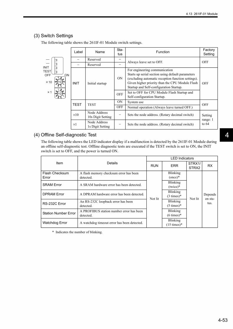
4.13 261IF-01 Module
4-53
4
(3) Switch SettingsThe following table shows the 261IF-01 Module switch settings.
(4) Offline Self-diagnostic TestThe following table shows the LED indicator display if a malfunction is detected by the 261IF-01 Module during an offline self-diagnostic test. Offline diagnostic tests are executed if the TEST switch is set to ON, the INIT switch is set to OFF, and the power is turned ON.
* Indicates the number of blinking.
Label Name Sta-tus Function Factory
Setting− Reserved −
Always leave set to OFF. OFF− Reserved −
INIT Initial startupON
For engineering communication Starts up serial section using default parameters (excluding automatic reception function settings). Given higher priority than the CPU Module Flash Startup and Self-configuration Startup.
OFF
OFF Set to OFF for CPU Module Flash Startup and Self-configuration Startup.
TEST TESTON System use
OFFOFF Normal operation (Always leave turned OFF.)
×10 Node Address 10s Digit Setting
− Sets the node address. (Rotary decimal switch) Setting range: 1 to 64×1 Node Address
1s Digit Setting− Sets the node address. (Rotary decimal switch)
TESTINIT
ONOFF
10
1
Item DetailsLED Indicators
RUN ERR STRX1/STRX2 RX
Flash Checksum Error
A flash memory checksum error has been detected.
Not lit
Blinking (once)*
Not litDepends on sta-
tus.
SRAM Error A SRAM hardware error has been detected.Blinking (twice)*
DPRAM Error A DPRAM hardware error has been detected.Blinking
(3 times)*
RS-232C Error An RS-232C loopback error has been detected.
Blinking (5 times)*
Station Number Error A PROFIBUS station number error has been detected.
Blinking (6 times)*
Watchdog Error A watchdog timeout error has been detected.Blinking
(15 times)*
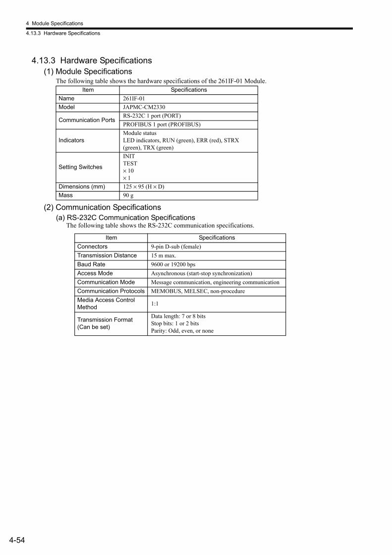
4 Module Specifications
4.13.3 Hardware Specifications
4-54
4.13.3 Hardware Specifications(1) Module Specifications
The following table shows the hardware specifications of the 261IF-01 Module.
(2) Communication Specifications(a) RS-232C Communication Specifications
The following table shows the RS-232C communication specifications.
Item SpecificationsName 261IF-01Model JAPMC-CM2330
Communication PortsRS-232C 1 port (PORT)PROFIBUS 1 port (PROFIBUS)
IndicatorsModule status LED indicators, RUN (green), ERR (red), STRX (green), TRX (green)
Setting Switches
INITTEST× 10× 1
Dimensions (mm) 125 × 95 (H × D)Mass 90 g
Item SpecificationsConnectors 9-pin D-sub (female)Transmission Distance 15 m max.Baud Rate 9600 or 19200 bps Access Mode Asynchronous (start-stop synchronization)Communication Mode Message communication, engineering communicationCommunication Protocols MEMOBUS, MELSEC, non-procedureMedia Access Control Method 1:1
Transmission Format (Can be set)
Data length: 7 or 8 bitsStop bits: 1 or 2 bitsParity: Odd, even, or none
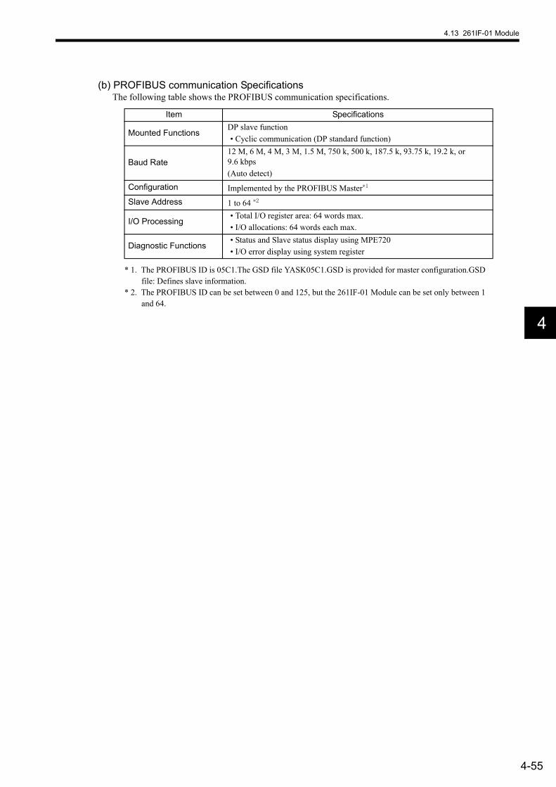
4.13 261IF-01 Module
4-55
4
(b) PROFIBUS communication SpecificationsThe following table shows the PROFIBUS communication specifications.
* 1. The PROFIBUS ID is 05C1.The GSD file YASK05C1.GSD is provided for master configuration.GSD file: Defines slave information.
* 2. The PROFIBUS ID can be set between 0 and 125, but the 261IF-01 Module can be set only between 1 and 64.
Item Specifications
Mounted FunctionsDP slave function• Cyclic communication (DP standard function)
Baud Rate12 M, 6 M, 4 M, 3 M, 1.5 M, 750 k, 500 k, 187.5 k, 93.75 k, 19.2 k, or 9.6 kbps(Auto detect)
Configuration Implemented by the PROFIBUS Master∗1
Slave Address 1 to 64 ∗2
I/O Processing• Total I/O register area: 64 words max.• I/O allocations: 64 words each max.
Diagnostic Functions• Status and Slave status display using MPE720• I/O error display using system register
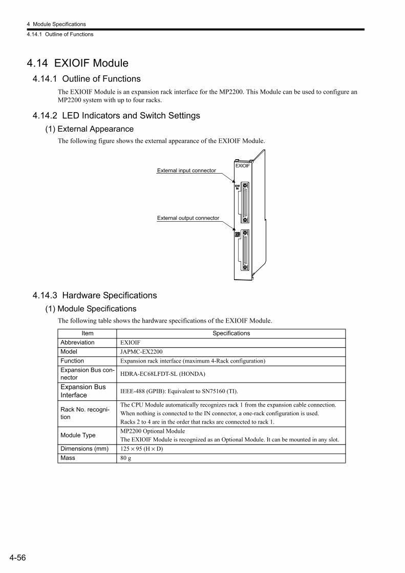
4 Module Specifications
4.14.1 Outline of Functions
4-56
4.14 EXIOIF Module4.14.1 Outline of Functions
The EXIOIF Module is an expansion rack interface for the MP2200. This Module can be used to configure an MP2200 system with up to four racks.
4.14.2 LED Indicators and Switch Settings(1) External Appearance
The following figure shows the external appearance of the EXIOIF Module.
4.14.3 Hardware Specifications(1) Module Specifications
The following table shows the hardware specifications of the EXIOIF Module.
EXIOIFExternal input connector
External output connector
Item SpecificationsAbbreviation EXIOIFModel JAPMC-EX2200Function Expansion rack interface (maximum 4-Rack configuration)Expansion Bus con-nector HDRA-EC68LFDT-SL (HONDA)
Expansion Bus Interface IEEE-488 (GPIB): Equivalent to SN75160 (TI).
Rack No. recogni-tion
The CPU Module automatically recognizes rack 1 from the expansion cable connection. When nothing is connected to the IN connector, a one-rack configuration is used. Racks 2 to 4 are in the order that racks are connected to rack 1.
Module TypeMP2200 Optional ModuleThe EXIOIF Module is recognized as an Optional Module. It can be mounted in any slot.
Dimensions (mm) 125 × 95 (H × D)Mass 80 g
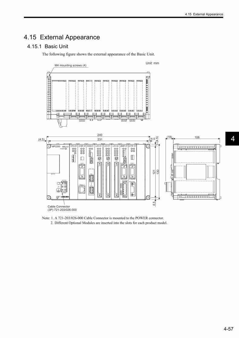
4.15 External Appearance
4-57
4
4.15 External Appearance4.15.1 Basic Unit
The following figure shows the external appearance of the Basic Unit.
Note: 1. A 721-203/026-000 Cable Connector is mounted to the POWER connector.2. Different Optional Modules are inserted into the slots for each product model.
(4.5
)13
012
14.
5
4.5(4.5)(18) 108
240231
MP2200 MBU-01 CPU-01 LIO-02SVB-01218IF-01 217IF-01260IF-01
CN1
CN2
100/200V
BATTEY
POWER
AC
PORT
RS422/465DeviceNet
PORTPORT
10Base-T
POWER
I/O
LIO-01
I/O
LIO-01
I/O
M- /
Unit: mm
Cable Connector (3P) 721-203/026-000
M4 mounting screws (4)
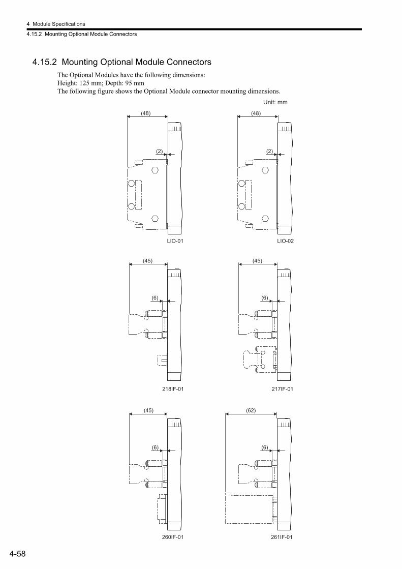
4 Module Specifications
4.15.2 Mounting Optional Module Connectors
4-58
4.15.2 Mounting Optional Module ConnectorsThe Optional Modules have the following dimensions:Height: 125 mm; Depth: 95 mmThe following figure shows the Optional Module connector mounting dimensions.
217IF-01
261IF-01260IF-01
218IF-01
(6)
(45)
(6)
(45)
(6)
(62)
(6)
(45)
LIO-01
(2)
(48)
LIO-02
(2)
(48)
Unit: mm
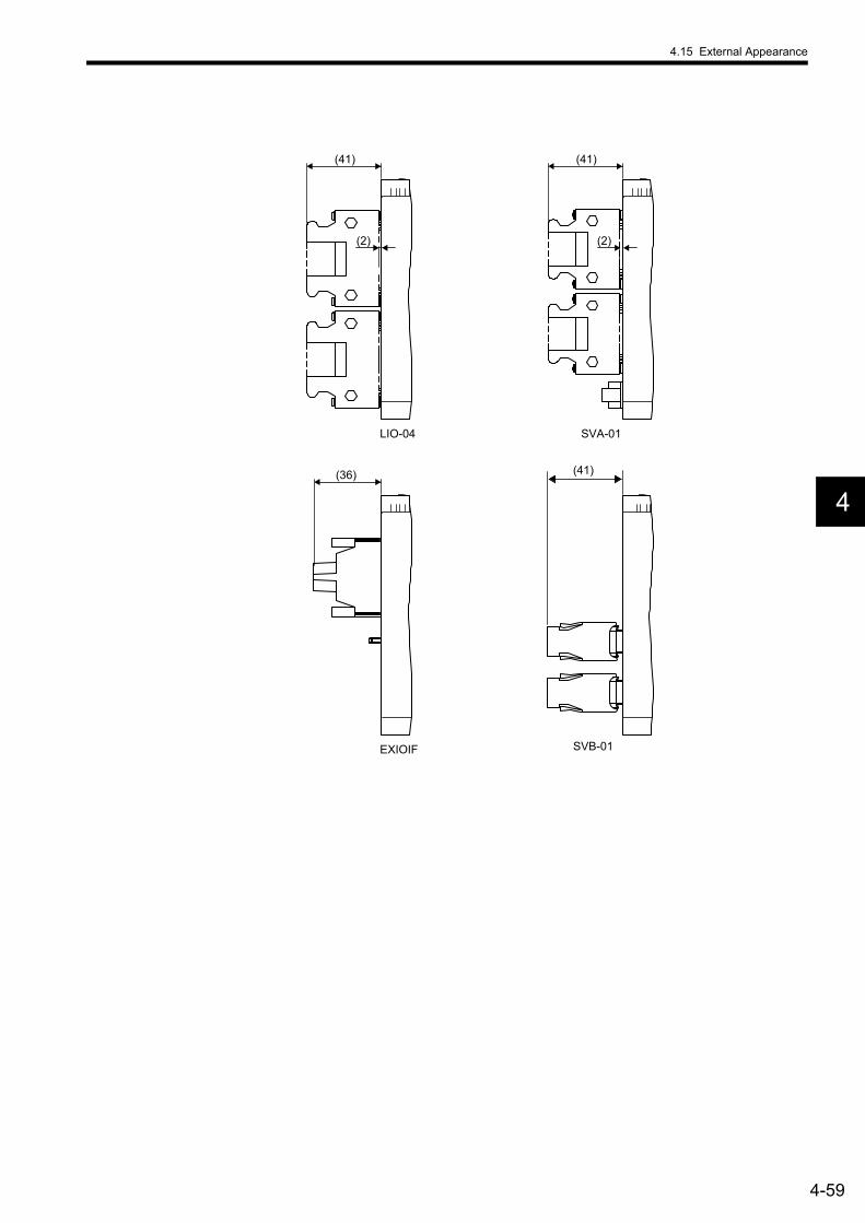
4.15 External Appearance
4-59
4
LIO-04
(2)
(41)
EXIOIF
(36) (41)
SVA-01
SVB-01
(2)
(41)
5-1
5
5Mounting and Wiring
This chapter explains how to handle the MP2200 and the connection methods for each Module.
5.1 Handling the MP2200 - - - - - - - - - - - - - - - - - - - - - - - - - - - - - - - - - - - - - - 5-25.1.1 Mounting the MP2200 - - - - - - - - - - - - - - - - - - - - - - - - - - - - - - - - - - - - - - - - - - - - - - 5-25.1.2 Replacing and Adding Optional Modules - - - - - - - - - - - - - - - - - - - - - - - - - - - - - - - - - 5-5
5.2 Module Connections - - - - - - - - - - - - - - - - - - - - - - - - - - - - - - - - - - - - - - - 5-85.2.1 Connecting Power Supply - - - - - - - - - - - - - - - - - - - - - - - - - - - - - - - - - - - - - - - - - - - 5-85.2.2 SVB-01 Module Connections - - - - - - - - - - - - - - - - - - - - - - - - - - - - - - - - - - - - - - - - 5-115.2.3 SVA-01 Module Connections - - - - - - - - - - - - - - - - - - - - - - - - - - - - - - - - - - - - - - - - 5-175.2.4 LIO Module Connections - - - - - - - - - - - - - - - - - - - - - - - - - - - - - - - - - - - - - - - - - - - 5-255.2.5 LIO-04 Module Connections - - - - - - - - - - - - - - - - - - - - - - - - - - - - - - - - - - - - - - - - - 5-375.2.6 218IF-01 Module Connections - - - - - - - - - - - - - - - - - - - - - - - - - - - - - - - - - - - - - - - 5-475.2.7 217IF-01 Module Connections - - - - - - - - - - - - - - - - - - - - - - - - - - - - - - - - - - - - - - - 5-515.2.8 260IF-01 Module Connections - - - - - - - - - - - - - - - - - - - - - - - - - - - - - - - - - - - - - - - 5-555.2.9 261IF-01 Module Connections - - - - - - - - - - - - - - - - - - - - - - - - - - - - - - - - - - - - - - - 5-585.2.10 EXIOIF Module Connections - - - - - - - - - - - - - - - - - - - - - - - - - - - - - - - - - - - - - - - 5-61
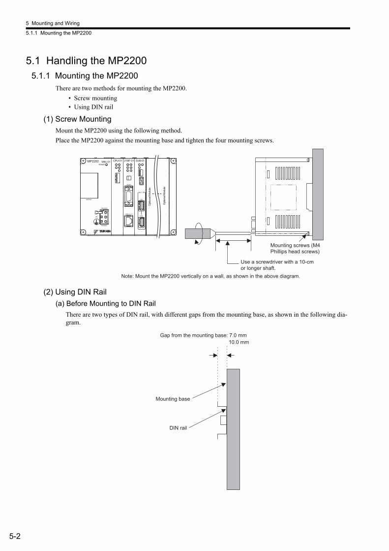
5 Mounting and Wiring
5.1.1 Mounting the MP2200
5-2
5.1 Handling the MP22005.1.1 Mounting the MP2200
There are two methods for mounting the MP2200.• Screw mounting• Using DIN rail
(1) Screw MountingMount the MP2200 using the following method.Place the MP2200 against the mounting base and tighten the four mounting screws.
(2) Using DIN Rail(a) Before Mounting to DIN Rail
There are two types of DIN rail, with different gaps from the mounting base, as shown in the following dia-gram.
MP2200 MBU-01 CPU-01 SVB-01218IF-01
CN1
CN2
100/200V
BATTEY
POWER
AC
PORT
10Base-T
POWER
M- /
Note: Mount the MP2200 vertically on a wall, as shown in the above diagram.
Opt
ional
Mod
ule
Opt
ional
Mod
ule
Mounting screws (M4 Phillips head screws)
Use a screwdriver with a 10-cm or longer shaft.
10.0 mm
Mounting base
DIN rail
Gap from the mounting base: 7.0 mm
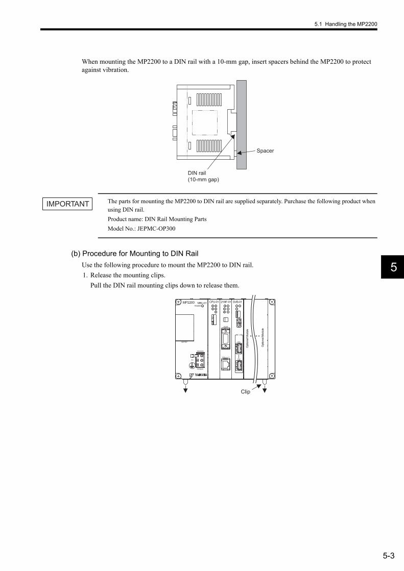
5.1 Handling the MP2200
5-3
5
When mounting the MP2200 to a DIN rail with a 10-mm gap, insert spacers behind the MP2200 to protect against vibration.
The parts for mounting the MP2200 to DIN rail are supplied separately. Purchase the following product when using DIN rail.Product name: DIN Rail Mounting PartsModel No.: JEPMC-OP300
(b) Procedure for Mounting to DIN RailUse the following procedure to mount the MP2200 to DIN rail.1. Release the mounting clips.
Pull the DIN rail mounting clips down to release them.
Spacer
DIN rail (10-mm gap)
IMPORTANT
MP2200 MBU-01 CPU-01 SVB-01218IF-01
CN1
CN2
100/200V
BATTEY
POWER
AC
PORT
10Base-T
POWER
M- /
Clip
Opt
ional
Mod
ule
Opt
ional
Mod
ule

5 Mounting and Wiring
5.1.1 Mounting the MP2200
5-4
2. Mount the MP2200 to the DIN rail.a) Hook the MP2200 into the top side of the DIN rail.b) Push the MP2200 towards the mounting base to secure it in place.
3. Lock the mounting clips.Push the DIN rail mounting clips to lock them in place.
4. Fix the MP2200 in place.Place end plates on either side of the MP2200 to secure it to the DIN rail.
This completes the installation procedure.
b)
a)
MP2200 MBU-01 CPU-01 SVB-01218IF-01
CN1
CN2
100/200V
BATTEY
POWER
AC
PORT
10Base-T
POWER
M- /
Clip
Opt
ional
Mod
ule
Opt
ional
Mod
ule
MP2200 MBU-01 CPU-01 SVB-01218IF-01
CN1
CN2
100/200V
BATTEY
POWER
AC
PORT
10Base-T
POWER
M- /
End plate
DIN rail
Opt
ional
Mod
ule
Opt
ional
Mod
ule

5.1 Handling the MP2200
5-5
5
5.1.2 Replacing and Adding Optional ModulesUse the following procedures to replace or add Optional Modules.
(1) Preparations1. Create a backup data file.
Use the MPE720 to save the MP2200 program on a computer.
2. Remove the MP2200.Turn OFF the power supply and disconnect all cables from the MP2200. Then remove the MP2200 from the panel or rack and place it on a workbench or other area with sufficient space.
(2) Removing Optional Modules1. Remove the battery cover.
Pull the notch on the side of the MP2200 towards you to remove the battery cover.
2. Remove the Optional Module panel.Insert the protruding part of the battery cover into the slot on top of the panel of Optional Module to unhook it, as shown in the diagram. Face the front of the battery cover towards you for this operation.
Remove the cover on the bottom in the same way.
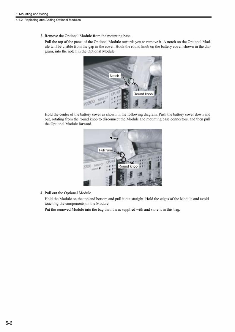
5 Mounting and Wiring
5.1.2 Replacing and Adding Optional Modules
5-6
3. Remove the Optional Module from the mounting base.Pull the top of the panel of the Optional Module towards you to remove it. A notch on the Optional Mod-ule will be visible from the gap in the cover. Hook the round knob on the battery cover, shown in the dia-gram, into the notch in the Optional Module.
Hold the center of the battery cover as shown in the following diagram. Push the battery cover down and out, rotating from the round knob to disconnect the Module and mounting base connectors, and then pull the Optional Module forward.
4. Pull out the Optional Module.Hold the Module on the top and bottom and pull it out straight. Hold the edges of the Module and avoid touching the components on the Module.Put the removed Module into the bag that it was supplied with and store it in this bag.
Round knob
Notch
Round knob
Fulcrum

5.1 Handling the MP2200
5-7
5
(3) Installing Optional Modules1. Insert the Optional Module.
Hold the top and bottom of the Module to be installed.
Guide rails are visible at the top and bottom of the Option Slot, as shown in the above diagram. Line up the Module with the guide rail and insert the Module straight. The FG bar on the inside bottom of the Unit Case may be damaged if the Module is not inserted straight.
2. Mount on to the mounting base.Once the Optional Module has been completely inserted, place your hand on the front face of the Optional Module and push hard until the Optional Module has been inserted into the mounting base connectors. The front face of the Optional Module and the hook will be aligned when the Optional Module has been installed properly.
3. Install the Optional Module panel.Place the hole on the bottom of the panel of the Optional Module onto the hook on the bottom of the MP2200.
Next, hook the hole at the top of the panel of the Optional Module onto the hook at the top of the MP2200.
Guide rail
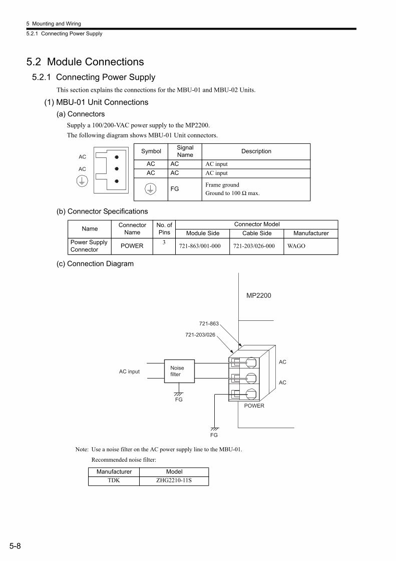
5 Mounting and Wiring
5.2.1 Connecting Power Supply
5-8
5.2 Module Connections5.2.1 Connecting Power Supply
This section explains the connections for the MBU-01 and MBU-02 Units.
(1) MBU-01 Unit Connections(a) Connectors
Supply a 100/200-VAC power supply to the MP2200.The following diagram shows MBU-01 Unit connectors.
(b) Connector Specifications
(c) Connection Diagram
Note: Use a noise filter on the AC power supply line to the MBU-01.
Recommended noise filter:
Symbol Signal Name Description
AC AC AC inputAC AC AC input
FGFrame groundGround to 100 Ω max.
Name Connector Name
No. of Pins
Connector ModelModule Side Cable Side Manufacturer
Power Supply Connector POWER 3 721-863/001-000 721-203/026-000 WAGO
Manufacturer ModelTDK ZHG2210-11S
AC
AC
AC
AC
MP2200
POWER
FG
FG
721-863
721-203/026
AC input Noise filter
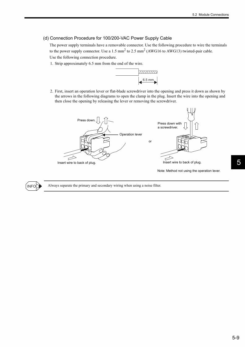
5.2 Module Connections
5-9
5
(d) Connection Procedure for 100/200-VAC Power Supply CableThe power supply terminals have a removable connector. Use the following procedure to wire the terminals to the power supply connector. Use a 1.5 mm2 to 2.5 mm2 (AWG16 to AWG13) twisted-pair cable.Use the following connection procedure.1. Strip approximately 6.5 mm from the end of the wire.
2. First, insert an operation lever or flat-blade screwdriver into the opening and press it down as shown by the arrows in the following diagrams to open the clamp in the plug. Insert the wire into the opening and then close the opening by releasing the lever or removing the screwdriver.
Always separate the primary and secondary wiring when using a noise filter.
6.5 mm
Operation lever
Press down.
Insert wire to back of plug.
or
Insert wire to back of plug.
Note: Method not using the operation lever.
Press down with a screwdriver.
INFO
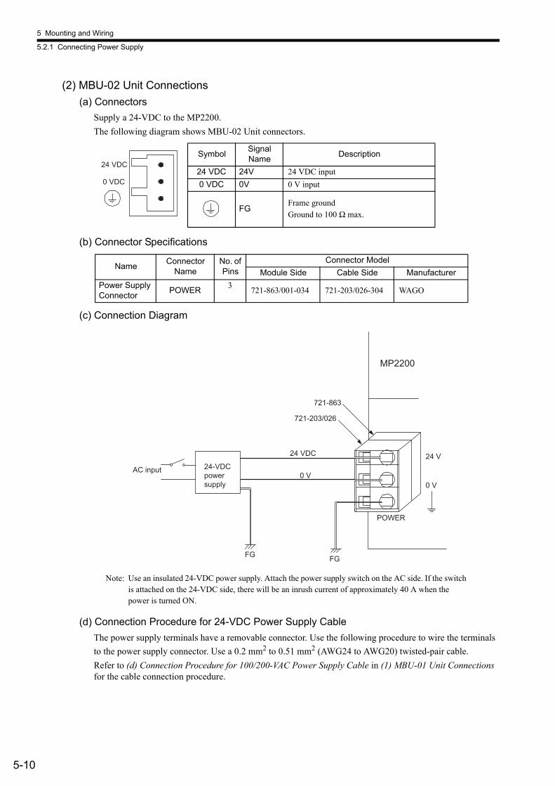
5 Mounting and Wiring
5.2.1 Connecting Power Supply
5-10
(2) MBU-02 Unit Connections(a) Connectors
Supply a 24-VDC to the MP2200.The following diagram shows MBU-02 Unit connectors.
(b) Connector Specifications
(c) Connection Diagram
Note: Use an insulated 24-VDC power supply. Attach the power supply switch on the AC side. If the switch is attached on the 24-VDC side, there will be an inrush current of approximately 40 A when the power is turned ON.
(d) Connection Procedure for 24-VDC Power Supply CableThe power supply terminals have a removable connector. Use the following procedure to wire the terminals to the power supply connector. Use a 0.2 mm2 to 0.51 mm2 (AWG24 to AWG20) twisted-pair cable.Refer to (d) Connection Procedure for 100/200-VAC Power Supply Cable in (1) MBU-01 Unit Connections for the cable connection procedure.
Symbol Signal Name Description
24 VDC 24V 24 VDC input0 VDC 0V 0 V input
FGFrame groundGround to 100 Ω max.
Name Connector Name
No. of Pins
Connector ModelModule Side Cable Side Manufacturer
Power Supply Connector POWER 3 721-863/001-034 721-203/026-304 WAGO
24 VDC
0 VDC
24 VDC
0 V
24 V
0 V
MP2200
POWER
FG FG
721-863
721-203/026
AC input 24-VDC power supply

5.2 Module Connections
5-11
5
5.2.2 SVB-01 Module ConnectionsThis section explains the connections for the SVB-01 Module.
(1) ConnectorsMECHATROLINK-I/MECHATROLINK-II connectors are used to connect the SVB-01 Module and the SERVOPACKs and distributed I/O.MECHATROLINK-I/MECHATROLINK-II connectors are shown in the following diagram.
• There are two connectors on the MECHATROLINK-I/MECHATROLINK-II, but the communication line supports only one channel.
• If the SVB-01 Module is connected at the end of a network, connect a JEPMC-W6022 Terminator to the other connec-tor.
• Both connectors perform the same function, so connections can be made to either.
(2) Connector Specifications
Pin No. Signal Name Description
1 (NC) Not used2 /DATA Signal -3 DATA Signal +4 SH Not used
Shell Shield Connects the shield wire.
M-I/II
CN1
CN2
INFO
Name Connector Name
No. of Pins
Connector ModelModule Side Cable Side Manufacturer
MECHATROLINK connector M-I / II 4 USB-AR41-T11 DUSB-APA41B1-C50 DDK Ltd.
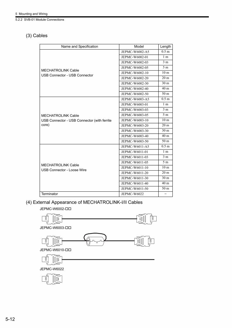
5 Mounting and Wiring
5.2.2 SVB-01 Module Connections
5-12
(3) Cables
(4) External Appearance of MECHATROLINK-I/II CablesJEPMC-W6002-
JEPMC-W6003-
JEPMC-W6010-
JEPMC-W6022
Name and Specification Model Length
MECHATROLINK CableUSB Connector - USB Connector
JEPMC-W6002-A5 0.5 mJEPMC-W6002-01 1 mJEPMC-W6002-03 3 mJEPMC-W6002-05 5 mJEPMC-W6002-10 10 mJEPMC-W6002-20 20 mJEPMC-W6002-30 30 mJEPMC-W6002-40 40 mJEPMC-W6002-50 50 m
MECHATROLINK CableUSB Connector - USB Connector (with ferrite core)
JEPMC-W6003-A5 0.5 mJEPMC-W6003-01 1 mJEPMC-W6003-03 3 mJEPMC-W6003-05 5 mJEPMC-W6003-10 10 mJEPMC-W6003-20 20 mJEPMC-W6003-30 30 mJEPMC-W6003-40 40 mJEPMC-W6003-50 50 m
MECHATROLINK CableUSB Connector - Loose Wire
JEPMC-W6011-A5 0.5 mJEPMC-W6011-01 1 mJEPMC-W6011-03 3 mJEPMC-W6011-05 5 mJEPMC-W6011-10 10 mJEPMC-W6011-20 20 mJEPMC-W6011-30 30 mJEPMC-W6011-40 40 mJEPMC-W6011-50 50 m
Terminator JEPMC-W6022 −

5.2 Module Connections
5-13
5
(5) SVB-01 Module System Configuration(a) Connecting the SVB-01 Module to the End of the MECHATROLINK Network
The following diagram shows a system configuration example.
Note: Insert a JEPMC-W6022 Terminator into the unused MECHATROLINK port.
MECHATROLINK-
I/O
MP2200 MBU-02 CPU-01 SVB-01218IF-01
CN1
CN2
BATTEY
POWER
DC
PORT
10Base-T
POWER
M- /
MP2200SVB-01
YASKAWA SERVOPACK 200V
SGDS-01A12A
SW1
CHARGE
CN3
A/B
CN1
CN2
CN4
L1L2
L2CL1C
B1/B2
U
V
W
CN6
YASKAWA SERVOPACK 200V
SGDS-01A12A
SW1
CHARGE
CN3
A/B
CN1
CN2
CN4
L1L2
L2CL1C
B1/B2
U
V
W
CN6
JEPMC-IO2310
VS mini V7
Inverter
SERVOPACKs/Inverters for up to 16 stations
Up to 21 stations including I/O
SERVOPACK SERVOPACK Repeater SERVOPACK
Terminator
Terminator
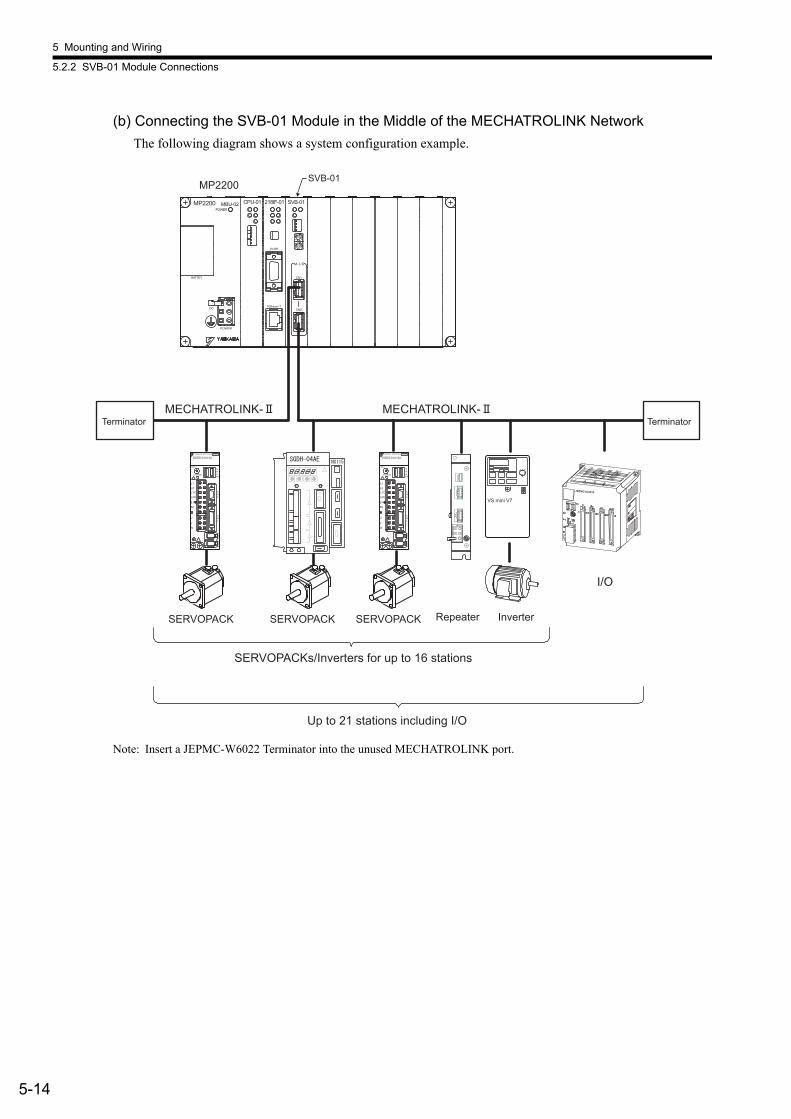
5 Mounting and Wiring
5.2.2 SVB-01 Module Connections
5-14
(b) Connecting the SVB-01 Module in the Middle of the MECHATROLINK NetworkThe following diagram shows a system configuration example.
Note: Insert a JEPMC-W6022 Terminator into the unused MECHATROLINK port.
MECHATROLINK-MECHATROLINK-
I/O
MP2200 MBU-02 CPU-01 SVB-01218IF-01
CN1
CN2
BATTEY
POWER
DC
PORT
10Base-T
POWER
M- /
MP2200SVB-01
YASKAWA SERVOPACK 200V
SGDS-01A12A
SW1
CHARGE
CN3
A/B
CN1
CN2
CN4
L1L2
L2CL1C
B1/B2
U
V
W
CN6
YASKAWA SERVOPACK 200V
SGDS-01A12A
SW1
CHARGE
CN3
A/B
CN1
CN2
CN4
L1L2
L2CL1C
B1/B2
U
V
W
CN6
JEPMC-IO2310
VS mini V7
SERVOPACKs/Inverters for up to 16 stations
Up to 21 stations including I/O
SERVOPACK SERVOPACK SERVOPACK Inverter Repeater
Terminator Terminator

5.2 Module Connections
5-15
5
(6) Connections between Devices(a) Cable Connections between the SVB-01 and I/O Units and the MP2200 and
SERVOPACKs
Note: The JEPMC-W6003- Cable has a ferrite core.
(b) Cable Connections between the SVB-01 and SGD- N and SGDB- AN SERVOPACKs
Note: 1. The JEPMC-6010- has a USB connector on one end and loose wires on the other end. Use an MR connector and wiring material to create a 1:N cable.
2. The terminating resistance for SGD- N ,SGDB- AN must be provided by the user. 3. Prepare the cables according to following MECHATROLINK-I specifications. Connections that do
not meet the specifications will prevent normal communication due to the influence of reflected waves or other factors. Total network length: 50 m max. Maximum number of slave stations: 14 stations max. Minimum distance between stations: 0.3 m min.
1
2
3
4
1
2
3
4
(NC)
DATA
DATA
SH
(NC)
/DATA
DATA
SH
JEPMC-W6003-
Shell Shell
Pin No. Name
Shield Shield
Name
Cable model number: JEPMC-W6002-
1
2
3
4
1
2
3
4
5
6
7
1
2
3
4
5
6
7
1
2
3
4
5
6
7
/DATA
DATA
SH
(NC) /DATA
DATA
TERM
FG
/DATA /DATA
/DATA
DATA
TERM
FG
/DATA
/DATA
DATA
TERM
FG
DATA DATA DATA
8 8 8
SVB-01
ShellShield
Name Name Name
Connect a terminator between pins 6 and 7.Resistance: 130 Ω ± 5%, 1/2 W
USB Connector
SERVOPACK SERVOPACK SERVOPACK (terminating)
Name
MR Connector MR Connector MR Connector
Cable model number: JEPMC-W6011-

5 Mounting and Wiring
5.2.2 SVB-01 Module Connections
5-16
(c) Terminator Connections
(d) Connection Example between the SVB-01, SERVOPACKs, and the IO2310
Note: 1. Use standard cables between Units.2. The total connection length (L1 + L2 + L3 +.... + Lu) must be no longer than 50 m.
The MP2200 has a built-in terminator.Insert a JEPMC-W6022 Terminator into (1) in the above diagram.
1
2
3
4
(NC)
/DATA
DATA
SH
130 Ω
Shell
Pin No. Name
Shield
Terminator model number: JEPMC-W6022
NS100SGDH-YASKAWA SERVOPACK
NS100SGDH-YASKAWA SERVOPACK
NS100SGDH-YASKAWA SERVOPACK
L1
L1
L2 Ln
CN1IN1 OUT1 IN2 OUT2
A1 A1 A1 A1B1B1 B1 B1
YASKAWAJEPMC-IO2310
MP2200 MBU-01 CPU-01 SVB-01218IF-01
CN1
CN2
100/200V
BATTEY
POWER
AC
PORT
10Base-T
POWER
M- /
Terminator
Opt
iona
l Mod
ule
Opt
iona
l Mod
ule
Terminator
IMPORTANT

5.2 Module Connections
5-17
5
5.2.3 SVA-01 Module ConnectionsThis section explains the connections for the SVA-01 Module.
(1) System Connection Example
(2) Connector and Cable Specifications(a) Servo Interface Connectors (CN1 and CN2)
Two SERVOPACKs
SGDH-04EASGDH-04EA
2 analog outputs/axis2 analog inputs/axis1 pulse input/axis
MP2200 MBU-02 CPU-01 SVB-01218IF-01
CN1
CN2
BATTEY
POWER
DC
PORT
10Base-T
POWER
M-I/II
MP2200SVA-01
SVA-01RUN
CH1
CH2
DC IN
OV
+24V
ERR
24-VDCpowersupply
These connectors connect the SVA-01 Module to two SERVOPACKs. They are connected using the following standard cable. • JEPMC-W2040- (For SGDH, SGDM, and SGDS SERVOPACKs)
Note: The customer must provide cables for the SGDA and SGDB SERVOPACKs.

5 Mounting and Wiring
5.2.3 SVA-01 Module Connections
5-18
(b) 24-V Input Connector (CN3)This connector connect the SVA-01 Module to +24 VDC as a Servo I/O power supply.
A screw terminal connector is used (BL3.5/2F-AU manufactured by Weidmuller)
(c) Servo Connector SpecificationsThe following table shows the connector specifications.
(d) Connection Procedure for 24-V Input Cable
Use a 0.2 mm2 to 0.51 mm2 (AWG24 to AWG20) twisted-pair cable.Use the following connection procedure.1. Strip the wire for approximately 6.5 mm.
Strip approximately 6.5 mm from the end of the wire.
Pin No. Signal Name Name
2 24V +24 VDC input
1 0V 0 VDC IN
OV
+24V
Name Connector Name
No. of Pins
Connector ModelCable Model Num-
bersModule side Cable side Manufac-turer
Servo interface connector 1 and connector 2
CN1CN2
36 10236-52A2JL
• Connector body: 10136-3000VE
• Shell:10336-52A0-008ÅiScrew lockingÅj10336-52F0-008ÅiOne-touch lockingÅj
3MJEPMC-W2040-(For the SGDH/SGDM/SGDS)
24-V input con-nector CN3 2 • BL3.5/2F-AU Weidmuller
The CN3 connector is included with the SVA-01 Module, but a cable is not included. The user must connect the cable.
Core
Sheath6.5 mm

5.2 Module Connections
5-19
5
2. Tighten the wires with the screws.Insert the wire into the opening and then tighten the screws to a tightening torque of approximately 0.3 to 04 N⋅m.
(e) Connector Pin Arrangement (CN1 and CN2)The following figure shows the 36-pin arrangement of CN1 and CN2.
Pin No. Signal Name Name
2 24V +24 VDC input
1 0V 0 V
+ side (pin number 2)
− side (pin number 1)
19201
2
35361718
Arrangement from Connector Wiring Side on Cable Side
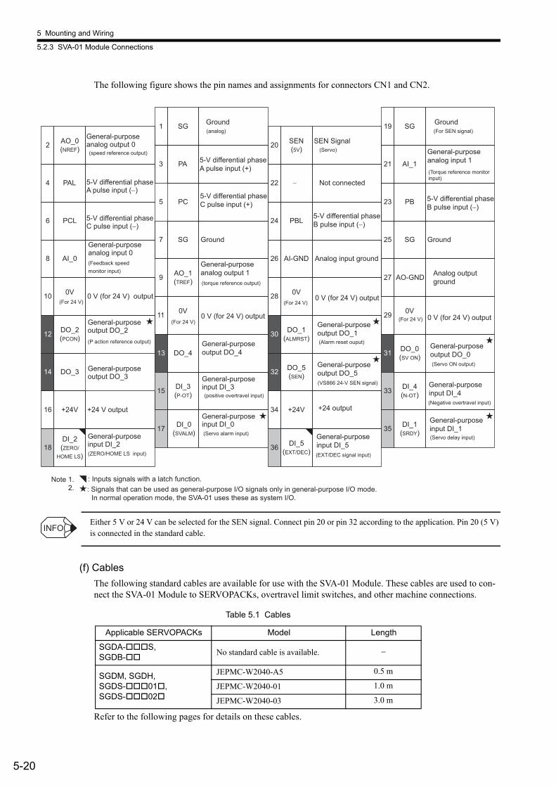
5 Mounting and Wiring
5.2.3 SVA-01 Module Connections
5-20
The following figure shows the pin names and assignments for connectors CN1 and CN2.
Either 5 V or 24 V can be selected for the SEN signal. Connect pin 20 or pin 32 according to the application. Pin 20 (5 V) is connected in the standard cable.
(f) CablesThe following standard cables are available for use with the SVA-01 Module. These cables are used to con-nect the SVA-01 Module to SERVOPACKs, overtravel limit switches, and other machine connections.
Refer to the following pages for details on these cables.
1 SG Ground(analog)
2 AO_0(NREF)
General-purpose analog output 0(speed reference output)
3 PA
4 PAL 5-V differential phase A pulse input (−)
6 PCL
5 PC
7 SG Ground
8 AI_0
9 AO_1(TREF)
General-purpose analog output 1(torque reference output)
10 0V(For 24 V)
0 V (for 24 V) output
11 0V
12 DO_2(PCON)
General-purpose output DO_2(P action reference output)
13 DO_4
14 DO_3
15 DI_3(P-OT) (positive overtravel input)
16 +24V +24 V output
17 DI_0(SVALM) (Servo alarm input)
18DI_2(ZERO/
HOME LS) (ZERO/HOME LS input)
19 SG Ground(For SEN signal)
20 SEN(5V)
SEN Signal(Servo)
32 DO_5(SEN)
(VS866 24-V SEN signal)
21 AI_1
General-purpose analog input 1
22 − Not connected
23 PB
24 PBL
25 SG Ground
26 AI-GND Analog input ground
27 AO-GND
28 0V
29 0V
30 DO_1(ALMRST) (Alarm reset ouput)
31 DO_0(SV ON)
(Servo ON output)
33 DI_4(N-OT)
(Negative overtravel input)34 +24V
36 DI_5(EXT/DEC) (EXT/DEC signal input)
35 DI_1(SRDY)
(Servo delay input)
Note 1. : Inputs signals with a latch function. 2. : Signals that can be used as general-purpose I/O signals only in general-purpose I/O mode.
In normal operation mode, the SVA-01 uses these as system I/O.
5-V differential phase C pulse input (−)
5-V differential phase A pulse input (+)
5-V differential phase C pulse input (+)
(For 24 V)
(For 24 V)
5-V differential phase B pulse input (−)
5-V differential phase B pulse input (−)
0 V (for 24 V) output(For 24 V)
General-purpose analog input 0(Feedback speed monitor input)
General-purpose output DO_3
General-purpose input DI_2
General-purpose input DI_0
General-purpose input DI_3
General-purpose output DO_4
0 V (for 24 V) output
0 V (for 24 V) output
General-purpose output DO_1
General-purpose output DO_5
+24 output
General-purpose input DI_5
General-purpose input DI_1
General-purpose input DI_4
General-purpose output DO_0
Analog output ground
(Torque reference monitor input)
Table 5.1 Cables
Applicable SERVOPACKs Model Length
SGDA- S,SGDB- No standard cable is available. −
SGDM, SGDH,SGDS- 01 ,SGDS- 02
JEPMC-W2040-A5 0.5 m
JEPMC-W2040-01 1.0 m
JEPMC-W2040-03 3.0 m
INFO
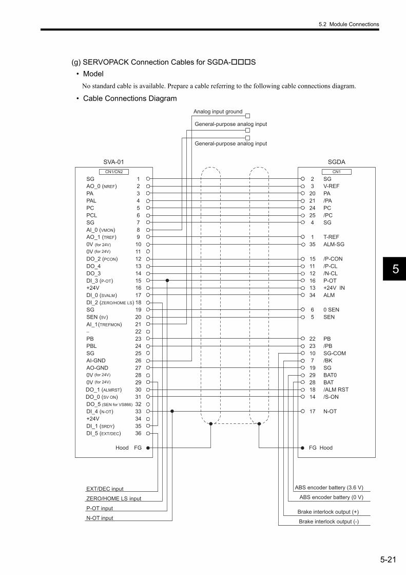
5.2 Module Connections
5-21
5
(g) SERVOPACK Connection Cables for SGDA- S• Model
No standard cable is available. Prepare a cable referring to the following cable connections diagram.
• Cable Connections Diagram
AO_0 (NREF)
PAL
PCL
AI_0 (VMON)
0V (for 24V)
DO_2 (PCON)
DO_3
+24V
DI_2 (ZERO/HOME LS)
SG
PA
PC
SG
AO_1 (TREF)
0V
DO_4
DI_3 (P-OT)
DI_0 (SVALM)
SEN (5V)
DO_5 (SEN for VS866)
−
PBL
AI-GND
0V
DO_1 (ALMRST)
+24V
DI_5 (EXT/DEC)
SG
AI_1(TREFMON)
PB
SG
AO-GND
0V
DO_0 (SV ON)
DI_4 (N-OT)
DI_1 (SRDY)
123456789
101112131415161718192021222324252627282930313233343536
SG2V-REF3PA20/PA21PC24/PC25SG4
T-REF1ALM-SG35
CN1/CN2
/P-CON15
CN1
SGDASVA-01
P-OT16+24V IN13ALM34
ZERO/HOME LS input
P-OT input
N-OT input
EXT/DEC input
General-purpose analog input
General-purpose analog input
Analog input ground
/BK7
0 SEN6SEN5
BAT029BAT28
PB22/PB23
SG19
/ALM RST18/S-ON14
N-OT17
Hood FG FG Hood
Brake interlock output (+)
ABS encoder battery (0 V)
ABS encoder battery (3.6 V)
Brake interlock output (-)
SG-COM10
/P-CL11/N-CL12
(for 24V)
(for 24V)
(for 24V)

5 Mounting and Wiring
5.2.3 SVA-01 Module Connections
5-22
(h) SERVOPACK Connection Cables for SGDB-• Model
No standard cable is available.
• Cable Connections Diagram
SGDB
AO_0 (NREF)
PAL
PCL
AI_0 (VTG)
0V (For 24 V)
DO_2 (PCON)
DO_3
+24V
DI_2 (ZERO/HOME LS)
SG
PA
PC
SG
AO_1 (TREF)
0V
DO_4
DI_3 (P-OT)
DI_0 (SVALM)
SEN (5V)
DO_5(SEN for VS866)
−
PBL
AI-GND
0V
DO_1 (ALMRST)
+24V
DI_5 (EXT/DEC)
SG
AI_1 (TMON)
PB
SG
AO-GND
0V
DO_0 (SV ON)
DI_4 (N-OT)
DI_1 (SRDY)
123456789
101112131415161718192021222324252627282930313233343536
SG2V-REF5PA33/PA34PC19/PC20SG6
T-REF9ALM-32
CN1/CN2
/P-CON 41
CN1
SVA-01
P-OT42+24V IN47ALM+31
ZERO/HOME LS input
P-OT input
N-OT input
EXT/DEC input
TGON- (/BRK-)28
SG10SEN4
BAT-22BAT+21
PB35/PB36
SG1TGON+ (/BRK+)27
/ALM-RST44/S-ON40
N-OT43
Brake interlock output (+)
ABS encoder battery (0 V)
ABS encoder battery (3.6 V)
Hood FG FG Hood
VTG-M17
TRQ-M16
Brake interlock output (−)
/S-RDY+29
/P-CL (User-set)45/N-CL (User-set)46
/S-RDY-30
(For 24 V)
(For 24 V)
(For 24 V)
(Torque monitor output)
(Control mode switch)
(Speed monitor output)

5.2 Module Connections
5-23
5
(i) SERVOPACK Connection Cables for SGDM/SGDH/SGDS- 01 / 02• Model
JEPMC-W2040-05: 0.5 mJEPMC-W2040-10: 1.0 mJEPMC-W2040-30: 3.0 m
• Appearance
• Cable Specifications
L
OTF
OTR
EXT
BAT0
BAT
/BRK+
NP:SVA NP:SERVOPAKGND
AI_2
AI_1
ZERO /BRK-
Diagram No. Name Model Qty Manufacturer Remarks
Plug on SVA end 10136-3000VE 1 Sumitomo 3M SolderedShell on SVA end 10336-52A0-008 1 Sumitomo 3MPlug on Servo end 10150-3000VE 1 Sumitomo 3M SolderedShell on Servo end 10350-52Z0-008 1 Sumitomo 3M
CableHP-SB/20276SR26 x AWG28
− Taiyo Cable Shield wire
Heat-shrinking tube F2 (Z) − Sumitomo Electric Industries. Ltd. Or equivalent
Wires UL1061 AWG28 − −
OTF: BrownOTR: OrangeEXT: BlackZERO: BAT: BlueBAT0: Purple*BRK+: Gray*BRK-: WhiteAI_1: WhiteAI_2: RedGND: Black
Marking tubes 2-mm dia., white 11 − Printing color: Black
Socket DF11-4DS-2C 1 Hirose Electric Co., Ltd.
Contacts DF11-2428SCF 1 Hirose Electric Co., Ltd.
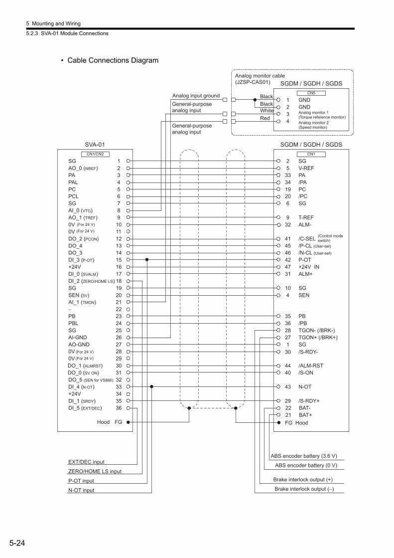
5 Mounting and Wiring
5.2.3 SVA-01 Module Connections
5-24
• Cable Connections Diagram
SGDM / SGDH / SGDS
AO_0 (NREF)
PAL
PCL
AI_0 (VTG)
0V
DO_2 (PCON)
DO_3
+24V
DI_2 (ZERO/HOME LS)
SG
PA
PC
SG
AO_1 (TREF)
0V
DO_4
DI_3 (P-OT)
DI_0 (SVALM)
SEN (5V)
DO_5 (SEN for VS866)
−
PBL
AI-GND
0V (For 24 V)
DO_1 (ALMRST)
+24V
DI_5 (EXT/DEC)
SG
AI_1 (TMON)
PB
SG
AO-GND
0V
DO_0 (SV ON)
DI_4 (N-OT)
DI_1 (SRDY)
123456789
101112131415161718192021222324252627282930313233343536
SG2V-REF5PA33/PA34PC19/PC20SG6
T-REF9ALM-32
CN1/CN2
/C-SEL41
CN1
SVA-01
P-OT42+24V IN47ALM+31
ZERO/HOME LS input
P-OT input
N-OT input
EXT/DEC input
TGON- (/BRK-)28
SG10SEN4
BAT-22BAT+21
PB35/PB36
SG1TGON+ (/BRK+)27
/ALM-RST44/S-ON40
N-OT43
Brake interlock output (+)
ABS encoder battery (0 V)
ABS encoder battery (3.6 V)
Hood FG
Brake interlock output (−)
/S-RDY+29
/P-CL (User-set)45/N-CL (User-set)46
Analog input groundGND1GND2
34
CN5
SGDM / SGDH / SGDSAnalog monitor cable(JZSP-CAS01)
BlackBlackWhiteRed
/S-RDY-30
FG Hood
(For 24 V)
(For 24 V)(For 24 V)
General-purpose analog input
General-purpose analog input
Analog monitor 1(Torque reference monitor)Analog monitor 2 (Speed monitor)
(Control mode switch)
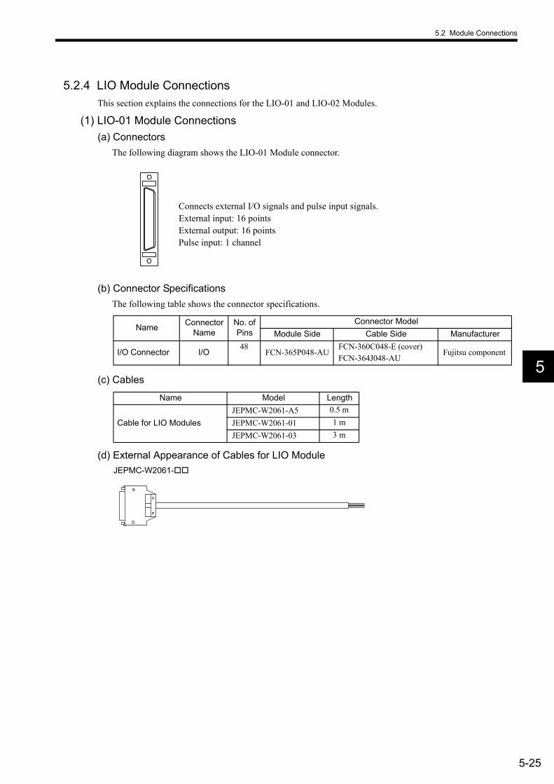
5.2 Module Connections
5-25
5
5.2.4 LIO Module ConnectionsThis section explains the connections for the LIO-01 and LIO-02 Modules.
(1) LIO-01 Module Connections(a) Connectors
The following diagram shows the LIO-01 Module connector.
(b) Connector SpecificationsThe following table shows the connector specifications.
(c) Cables
(d) External Appearance of Cables for LIO ModuleJEPMC-W2061-
Connects external I/O signals and pulse input signals.External input: 16 pointsExternal output: 16 pointsPulse input: 1 channel
Name Connector Name
No. of Pins
Connector ModelModule Side Cable Side Manufacturer
I/O Connector I/O48
FCN-365P048-AUFCN-360C048-E (cover)FCN-364J048-AU
Fujitsu component
Name Model Length
Cable for LIO ModulesJEPMC-W2061-A5 0.5 mJEPMC-W2061-01 1 mJEPMC-W2061-03 3 m

5 Mounting and Wiring
5.2.4 LIO Module Connections
5-26
(e) Connector Pin ArrangementThe following table shows the connector pin arrangement of the LIO-01 Module.
Note: P: Power input; I: Input signal; O: Open-collector output
Pin Num-ber
Signal Name I/O Remarks
Pin Num-ber
Signal Name I/O Remarks
A1 PA I Phase-A pulse (+) B1 PAL I Phase-A pulse (−)A2 PB I Phase-B pulse (+) B2 PBL I Phase-B pulse (−)
A3 PC I Phase-Z pulse (+) B3 PCL5 I Phase-Z pulse (−5 V input)
A4 GND I Pulse input ground B4 PCL12 I Phase-Z pulse (−12 V input)
A5 DO_COM P Output common B5 DO_COM P Output commonA6 DO_24V P 24 V input B6 DO_24V P 24 V inputA7 DO_15 O Output 15 B7 DO_14 O Output 14A8 DO_13 O Output 13 B8 DO_12 O Output 12A9 DO_11 O Output 11 B9 DO_10 O Output 10
A10 DO_09 O Output 9 B10 DO_08 O Output 8A11 DO_07 O Output 7 B11 DO_06 O Output 6A12 DO_05 O Output 5 B12 DO_04 O Output 4A13 DO_03 O Output 3 B13 DO_02 O Output 2A14 DO_01 O Output 1 B14 DO_00 O Output 0A15 DI_15 I Input 15 B15 DI_14 I Input 14A16 DI_13 I Input 13 B16 DI_12 I Input 12A17 DI_11 I Input 11 B17 DI_10 I Input 10A18 DI_09 I Input 9 B18 DI_08 I Input 8A19 DI_07 I Input 7 B19 DI_06 I Input 6A20 DI_05 I Input 5 B20 DI_04 I Input 4A21 DI_03 I Input 3 B21 DI_02 I Input 2A22 DI_01 I Input 1 B22 DI_00 I Input 0A23 DI_COM0 P Input common 0 B23 DI_COM1 P Input common 1A24 FG − Frame ground B24 FG − Frame ground

5.2 Module Connections
5-27
5
(f) Input CircuitThe following table shows the LIO-01 Module input circuit specifications.
Digital Input Circuit (Sink Mode Input)Åj
Digital Input Circuit (Source Mode Input)
Item SpecificationsInputs 16 pointsInput Format Sink mode/source mode inputsIsolation Method PhotocouplerInput Voltage ±24 VDC ±20 %Input Current 4.1 mA (typ.)ON Voltage/Current 15 V min./ 2.0 mA min.OFF Voltage/Current 5 V max./1.0 mA max.ON Time/OFF Time ON: 1 ms max., OFF: 1 ms max.Number of Commons 8 (DI_COM0: DI_00 to DI_07, DI_COM1: DI_08 to DI_15)
Other Functions
• DI-00 (interrupt input)DI-00 is shared with interrupts. If DI-00 is turned ON while interrupts are enabled, the interrupt processing drawing is executed.
• DI-01 (pulse latch input)DI-01 is shared with pulse latch inputs. If DI-01 is turned ON while pulse latch inputs are enabled, the pulse counter will be latched.
5.6 kΩ/0.5 W
Vcc
680 Ω
DI_COM
+24 V
DI_IN
22 kΩ
1 kΩ
2200 PF0.01 µF
024
Input register
5.6 kΩ/0.5 W
Vcc
680 Ω
DI_COM
+24 V
DI_IN
22 kΩ
1 kΩ
2200 PF0.01 µF
024
Input register
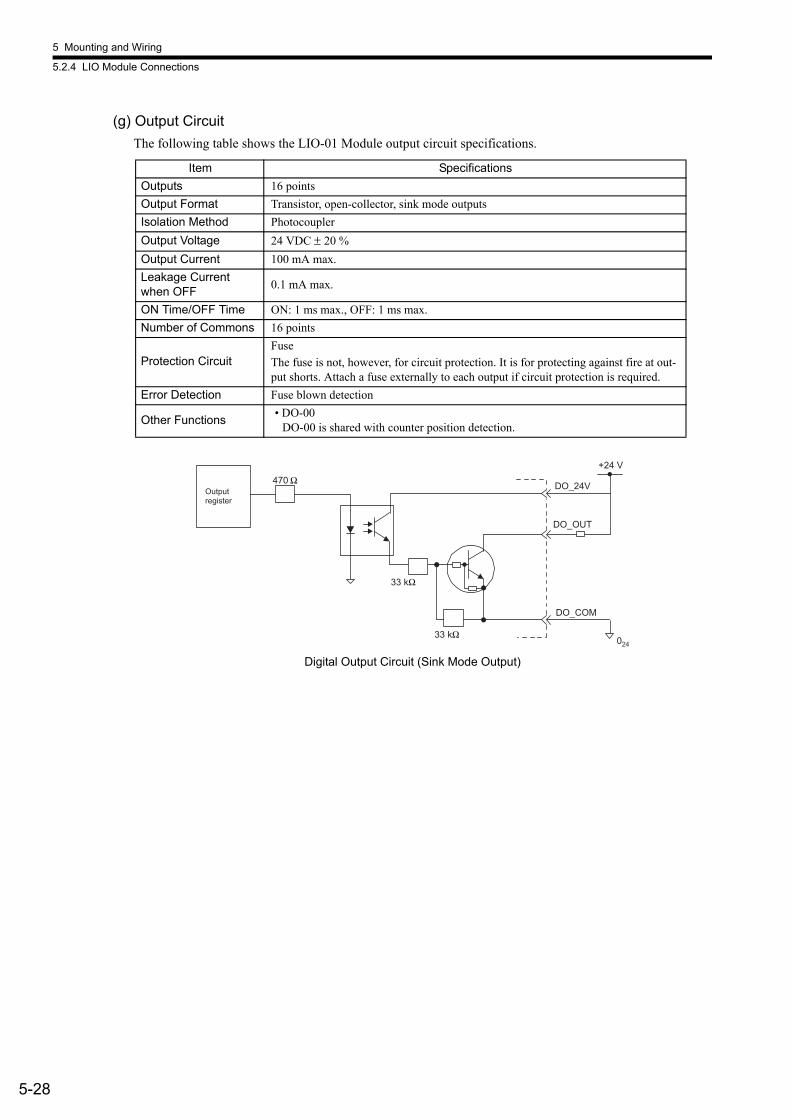
5 Mounting and Wiring
5.2.4 LIO Module Connections
5-28
(g) Output CircuitThe following table shows the LIO-01 Module output circuit specifications.
Digital Output Circuit (Sink Mode Output)
Item SpecificationsOutputs 16 pointsOutput Format Transistor, open-collector, sink mode outputsIsolation Method PhotocouplerOutput Voltage 24 VDC ± 20 %Output Current 100 mA max.Leakage Current when OFF 0.1 mA max.
ON Time/OFF Time ON: 1 ms max., OFF: 1 ms max.Number of Commons 16 points
Protection CircuitFuseThe fuse is not, however, for circuit protection. It is for protecting against fire at out-put shorts. Attach a fuse externally to each output if circuit protection is required.
Error Detection Fuse blown detection
Other Functions • DO-00DO-00 is shared with counter position detection.
470 Ω
33 kΩ
33 kΩ 024
DO_24V
DO_OUT
DO_COM
+24 V
Output register

5.2 Module Connections
5-29
5
(h) Pulse Input CircuitThe following table shows the LIO-01 Module pulse input circuit specifications.
Pulse Input Circuit
Item SpecificationsNumber of Points 1 (Phase-A/B/Z input)
Input Circuit Phase-A/B: 5-V differential input, not isolated, max. frequency: 4 MHz Phase-Z: 5-V/12-V photocoupler input, max. frequency: 500 kHz
Input Mode Phase-A/B, signed, incremental/decremental
Latch Input Pulse latch on phase-Z or DI-01. Response time: 5 µs max. for phase-Z input; 60 µs max. for DI-01 input.
Other Functions Coincidence detection, counter preset, and counter clear
220 Ω
+5 V
0 V
A1
220 Ω
PA
PAL
PB
PBL
GND
B1
A2
B2
B3
B4
A4
A3
+5 V
PC
PCL5
PCL12
330 Ω
680 Ω
Phase A
Pulse generator
Phase B
Latch input or phase Z pulse
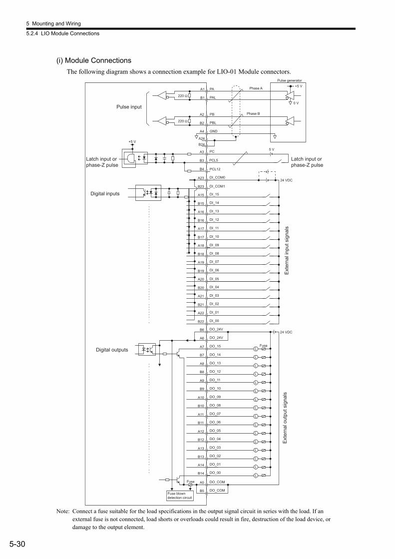
5 Mounting and Wiring
5.2.4 LIO Module Connections
5-30
(i) Module ConnectionsThe following diagram shows a connection example for LIO-01 Module connectors.
Note: Connect a fuse suitable for the load specifications in the output signal circuit in series with the load. If an external fuse is not connected, load shorts or overloads could result in fire, destruction of the load device, or damage to the output element.
220 Ω
220 Ω
+5 V
0 V
+5 V
L
L
L
L
L
L
L
5 V
L
L
L
L
L
L
L
L
L
24 VDC
A2
B2
A4
PB
PBL
GND
PC
PCL5
PCL12
A3
A24B24
B3
B4
DI_COM0
DI_15
DI_14
DI_13
DI_12
DI_11
DI_10
DI_09
DI_08
DI_COM1
DI_07
DI_06
DI_05
DI_04
DI_03
DI_02
DI_01
DI_00
DO_15
DO_14
DO_13
DO_12
DO_11
DO_10
DO_09
DO_24V
DO_24V
DO_08
DO_07
DO_06
DO_05
DO_04
DO_03
DO_02
DO_01
DO_00
DO_COM
DO_COM
B6
A6
A7
B7
A8
B8
A9
B9
A10
B10
A11
B11
A12
B12
A13
B13
A14
B14
A5
B5
A23
B23
A15
B15
A16
B16
A17
B17
A18
B18
A19
B19
A20
B20
A21
B21
A22
B22
PA
PAL
A1
B1
24 VDC
Phase A
Pulse generator
Fuse
Pulse input
Latch input or phase-Z pulse
Latch input or phase-Z pulse
Digital inputs
Digital outputs
Phase B
Fuse
Fuse blown detection circuit
Exte
rnal
out
put s
igna
ls
Exte
rnal
inpu
t sig
nals

5.2 Module Connections
5-31
5
(2) LIO-02 Module(a) Connectors
The following diagram shows the LIO-02 Module connector.
(b) Connector SpecificationsThe following table shows the connector specifications.
(c) Cables
(d) External Appearance of Cables for LIO ModuleJEPMC-W2061-
Connects external I/O signals and pulse input signals.External input: 16 pointsExternal output: 16 pointsPulse input: 1 channel
Name Connector Name
No. of Pins
Connector ModelModule Side Cable Side Manufacturer
I/O Connector I/O48
FCN-365P048-AUFCN-360C048-E (cover)FCN-364J048-AU
Fujitsu compo-nent
Name Model Length
Cable for LIO ModulesJEPMC-W2061-A5 0.5 mJEPMC-W2061-01 1 mJEPMC-W2061-03 3 m

5 Mounting and Wiring
5.2.4 LIO Module Connections
5-32
(e) Connector Pin ArrangementThe following table shows the connector pin arrangement for the LIO-02 Module.
Note: P: Power input; I: Input signal; O: Open-collector output
Pin Num-ber
Signal Name I/O RemarksPin
Num-ber
Signal Name I/O Remarks
A1 PA I Phase-A pulse (+) B1 PAL I Phase-A pulse (−)A2 PB I Phase-B pulse (+) B2 PBL I Phase-B pulse (−)
A3 PC I Phase-Z pulse (+) B3 PCL5 I Phase-Z pulse (−5 V input)
A4 GND I Pulse input ground B4 PCL12 I Phase-Z pulse (−12 V input)
A5 DO_COM P Output common B5 DO_COM P Output commonA6 DO_24V P 24 V input B6 DO_24V P 24 V inputA7 DO_15 O Output 15 B7 DO_14 O Output 14A8 DO_13 O Output 13 B8 DO_12 O Output 12A9 DO_11 O Output 11 B9 DO_10 O Output 10A10 DO_09 O Output 9 B10 DO_08 O Output 8A11 DO_07 O Output 7 B11 DO_06 O Output 6A12 DO_05 O Output 5 B12 DO_04 O Output 4A13 DO_03 O Output 3 B13 DO_02 O Output 2A14 DO_01 O Output 1 B14 DO_00 O Output 0A15 DI_15 I Input 15 B15 DI_14 I Input 14A16 DI_13 I Input 13 B16 DI_12 I Input 12A17 DI_11 I Input 11 B17 DI_10 I Input 10A18 DI_09 I Input 9 B18 DI_08 I Input 8A19 DI_07 I Input 7 B19 DI_06 I Input 6A20 DI_05 I Input 5 B20 DI_04 I Input 4A21 DI_03 I Input 3 B21 DI_02 I Input 2A22 DI_01 I Input 1 B22 DI_00 I Input 0A23 DI_COM0 P Input common 0 B23 DI_COM1 P Input common 1A24 FG − Frame ground B24 FG − Frame ground

5.2 Module Connections
5-33
5
(f) Input CircuitThe following table shows the LIO-02 Module input circuit specifications.
Digital Input Circuit (Sink Mode Input)
Digital Input Circuit (Source Mode Input)
Item SpecificationsInputs 16 pointsInput Format Sink mode/source mode inputsIsolation Method PhotocouplerInput Voltage ±24 VDC ± 20 %Input Current 4.1 mA (typ.)ON Voltage/Current 15 V min./ 2.0 mA min.OFF Voltage/Current 5 V max./1.0 mA max.ON Time/OFF Time ON: 1 ms max., OFF: 1 ms max.Number of Commons 8 (DI_COM0: DI_00 to DI_07, DI_COM1: DI_08 to DI_15)
Other Functions
• DI-00 (interrupt input)DI-00 is shared with interrupts. If DI-00 is turned ON while interrupts are enabled, the interrupt processing drawing is executed.
• DI-01 (pulse latch input)DI-01 is shared with pulse latch inputs. If DI-01 is turned ON while pulse latch inputs are enabled, the pulse counter will be latched.
5.6 kΩ/0.5 W
Vcc
680 Ω
DI_COM
+24 V
DI_IN
22 kΩ
1 kΩ
2200 PF0.01 µF
024
Input register
5.6 kΩ/0.5 W
Vcc
680 Ω
DI_COM
+24 V
DI_IN
22 kΩ
1 kΩ
2200 PF0.01 µF
024
Input register

5 Mounting and Wiring
5.2.4 LIO Module Connections
5-34
(g) Output CircuitThe following table shows the LIO-02 Module output circuit specifications.
Digital Output Circuit (Source Mode Output)
Item SpecificationsOutputs 16 pointsOutput Format Transistor, open-collector, source mode outputsIsolation Method PhotocouplerOutput Voltage 24 VDC ±20 %Output Current 100 mA max.Leakage Current when OFF 0.1 mA max.
ON Time/OFF Time ON: 1 ms max., OFF: 1 ms max.Number of Commons 16 points
Protection CircuitFuseThe fuse is not, however, for circuit protection. It is for protecting against fire at out-put shorts. Attach a fuse externally to each output if circuit protection is required.
Error Detection Fuse blown detection
Other Functions• DO-00DO-00 is shared with counter position detection.
024
+24 V
DO_24V
470 Ω
DO_OUT
DO_COM
33 kΩ
33 kΩ
Output register
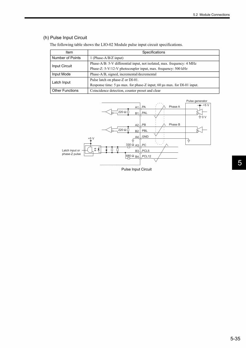
5.2 Module Connections
5-35
5
(h) Pulse Input CircuitThe following table shows the LIO-02 Module pulse input circuit specifications.
Pulse Input Circuit
Item SpecificationsNumber of Points 1 (Phase-A/B/Z input)
Input CircuitPhase-A/B: 5-V differential input, not isolated, max. frequency: 4 MHzPhase-Z: 5-V/12-V photocoupler input, max. frequency: 500 kHz
Input Mode Phase-A/B, signed, incremental/decremental
Latch InputPulse latch on phase-Z or DI-01.Response time: 5 µs max. for phase-Z input; 60 µs max. for DI-01 input.
Other Functions Coincidence detection, counter preset and clear
220 Ω
+5 V
0 V
A1
220 Ω
PA
PAL
PB
PBL
GND
B1
A2
B2
A4
B3
B4
A3
+5 V
PC
PCL5
PCL12
330 Ω
680 Ω
Phase A
Pulse generator
Phase B
Latch input or phase-Z pulse
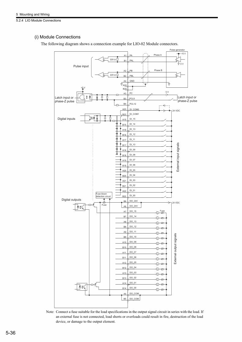
5 Mounting and Wiring
5.2.4 LIO Module Connections
5-36
(i) Module ConnectionsThe following diagram shows a connection example for LIO-02 Module connectors.
Note: Connect a fuse suitable for the load specifications in the output signal circuit in series with the load. If an external fuse is not connected, load shorts or overloads could result in fire, destruction of the load device, or damage to the output element.
220 Ω
+5 V
0 V
220 Ω
+5 V
L
L
L
L
L
L
L
5 V
L
L
L
L
L
L
L
L
L
24 VDC
A2
B2
A4
PB
PBL
GND
PC
PCL5
PCL12
A3
B3
B4
DI_COM0
DI_15
DI_14
DI_13
DI_12
DI_11
DI_10
DI_09
DI_08
DI_COM1
DI_07
DI_06
DI_05
DI_04
DI_03
DI_02
DI_01
DI_00
DO_24V
DO_24V
DO_15
DO_14
DO_13
DO_12
DO_11
DO_10
DO_09
DO_08
DO_07
DO_06
DO_05
DO_04
DO_03
DO_02
DO_01
DO_00
DO_COM
DO_COM
B6
A6
A7
B7
A8
B8
A9
B9
A10
B10
A11
B11
A12
B12
A13
B13
A14
B14
A5
B5
A23
B23
A15
B15
A16
B16
A17
B17
A18
B18
A19
B19
A20
B20
A21
B21
A22
B22
PA
PAL
A1
B1
24 VDC
A24B24
Phase A
Pulse generator
Fuse
Pulse input
Digital inputs
Digital outputs
Phase B
Fuse
Latch input or phase-Z pulse
Latch input or phase-Z pulse
Exte
rnal
out
put s
igna
ls
Fuse blown detection circuit
Exte
rnal
inpu
t sig
nals
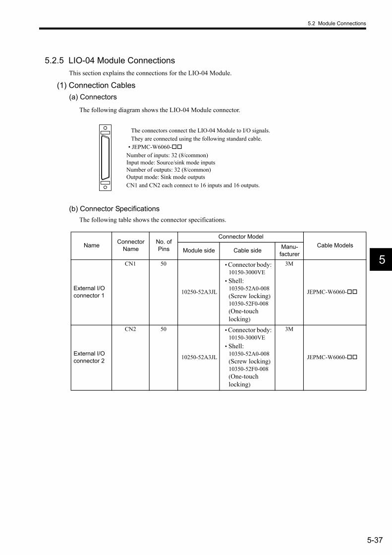
5.2 Module Connections
5-37
5
5.2.5 LIO-04 Module ConnectionsThis section explains the connections for the LIO-04 Module.
(1) Connection Cables(a) Connectors
The following diagram shows the LIO-04 Module connector.
(b) Connector SpecificationsThe following table shows the connector specifications.
The connectors connect the LIO-04 Module to I/O signals. They are connected using the following standard cable.
• JEPMC-W6060-Number of inputs: 32 (8/common) Input mode: Source/sink mode inputsNumber of outputs: 32 (8/common) Output mode: Sink mode outputsCN1 and CN2 each connect to 16 inputs and 16 outputs.
Name Connector Name
No. of Pins
Connector ModelCable Models
Module side Cable side Manu-facturer
External I/O connector 1
CN1 50
10250-52A3JL
• Connector body: 10150-3000VE
• Shell:10350-52A0-008(Screw locking)10350-52F0-008(One-touch locking)
3M
JEPMC-W6060-
External I/O connector 2
CN2 50
10250-52A3JL
• Connector body: 10150-3000VE
• Shell:10350-52A0-008(Screw locking)10350-52F0-008(One-touch locking)
3M
JEPMC-W6060-
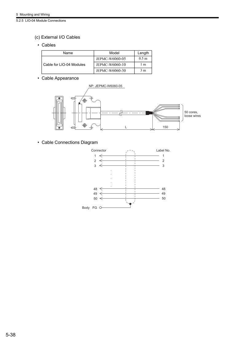
5 Mounting and Wiring
5.2.5 LIO-04 Module Connections
5-38
(c) External I/O Cables
• Cables
• Cable Appearance
• Cable Connections Diagram
Name Model Length
Cable for LIO-04 ModulesJEPMC-W6060-05 0.5 m
JEPMC-W6060-10 1 m
JEPMC-W6060-30 3 m
L 150
NP: JEPMC-W6060-05
50 cores, loose wires
FG
.
.
.
.
.484950
123
484950
123
Connector
Body
Label No.
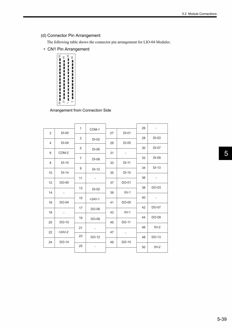
5.2 Module Connections
5-39
5
(d) Connector Pin ArrangementThe following table shows the connector pin arrangement for LIO-04 Modules.
• CN1 Pin Arrangement
50 49 25 24
26 27 1 2
Arrangement from Connection Side
24
22
20
18
16
14
12
10
8
6
4
2
DO-14
+24V-2
DO-10
DO-04
DO-00
DI-14
DI-10
COM-2
DI-04
DI-00
25
23
21
19
17
15
13
11
9
7
5
3
1
DO-12
DO-08
DO-06
+24V-1
DI-02
DI-12
DI-08
DI-06
DI-02
COM-1
49
47
45
43
41
39
37
35
33
31
29
27
DO-15
DO-11
0V-1
DO-05
0V-1
DO-01
DI-15
DI-11
DI-05
DI-01
50
48
46
44
42
40
38
36
34
32
30
28
26
0V-2
DO-13
0V-2
DO-09
DO-07
DO-03
DI-13
DI-09
DI-07
DI-03
−
−
−
−
−
−
−
−
−
−
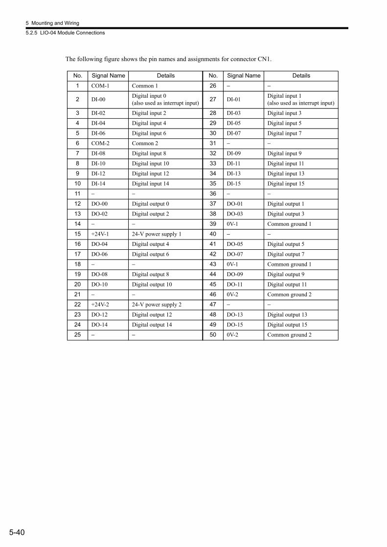
5 Mounting and Wiring
5.2.5 LIO-04 Module Connections
5-40
The following figure shows the pin names and assignments for connector CN1.
No. Signal Name Details No. Signal Name Details
1 COM-1 Common 1 26 − −
2 DI-00 Digital input 0(also used as interrupt input) 27 DI-01 Digital input 1
(also used as interrupt input)
3 DI-02 Digital input 2 28 DI-03 Digital input 3
4 DI-04 Digital input 4 29 DI-05 Digital input 5
5 DI-06 Digital input 6 30 DI-07 Digital input 7
6 COM-2 Common 2 31 − −
7 DI-08 Digital input 8 32 DI-09 Digital input 9
8 DI-10 Digital input 10 33 DI-11 Digital input 11
9 DI-12 Digital input 12 34 DI-13 Digital input 13
10 DI-14 Digital input 14 35 DI-15 Digital input 15
11 − − 36 − −
12 DO-00 Digital output 0 37 DO-01 Digital output 1
13 DO-02 Digital output 2 38 DO-03 Digital output 3
14 − − 39 0V-1 Common ground 1
15 +24V-1 24-V power supply 1 40 − −
16 DO-04 Digital output 4 41 DO-05 Digital output 5
17 DO-06 Digital output 6 42 DO-07 Digital output 7
18 − − 43 0V-1 Common ground 1
19 DO-08 Digital output 8 44 DO-09 Digital output 9
20 DO-10 Digital output 10 45 DO-11 Digital output 11
21 − − 46 0V-2 Common ground 2
22 +24V-2 24-V power supply 2 47 − −
23 DO-12 Digital output 12 48 DO-13 Digital output 13
24 DO-14 Digital output 14 49 DO-15 Digital output 15
25 − − 50 0V-2 Common ground 2

5.2 Module Connections
5-41
5
• CN2 Pin Arrangement
50
49
25
24
26
27 1
2
Arrangement from Connection Side
24
22
20
18
16
14
12
10
8
6
4
2
DO-30
+24V-4
DO-26
DO-20
DO-16
DI-30
DI-26
COM-4
DI-20
DI-16
25
23
21
19
17
15
13
11
9
7
5
3
1
DO-28
DO-24
DO-22
+24V-3
DI-18
DI-28
DI-24
DI-22
DI-18
COM-3
49
47
45
43
41
39
37
35
33
31
29
27
DO-31
DO-27
0V-3
DO-21
0V-3
DO-17
DI-31
DI-27
DI-21
DI-17
50
48
46
44
42
40
38
36
34
32
30
28
26
0V-4
DO-29
0V-4
DO-25
DO-23
DO-19
DI-29
DI-25
DI-23
DI-19
−
−
−
−
−
−
−
−
−
−
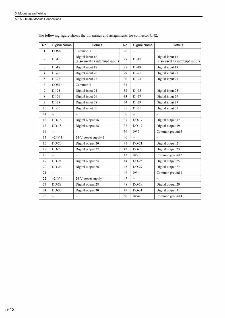
5 Mounting and Wiring
5.2.5 LIO-04 Module Connections
5-42
The following figure shows the pin names and assignments for connector CN2.
No. Signal Name Details No. Signal Name Details
1 COM-3 Common 3 26 − −
2 DI-16Digital input 16(also used as interrupt input) 27 DI-17
Digital input 17(also used as interrupt input)
3 DI-18 Digital input 18 28 DI-19 Digital input 19
4 DI-20 Digital input 20 29 DI-21 Digital input 21
5 DI-22 Digital input 22 30 DI-23 Digital input 23
6 COM-4 Common 4 31 − −
7 DI-24 Digital input 24 32 DI-25 Digital input 25
8 DI-26 Digital input 26 33 DI-27 Digital input 27
9 DI-28 Digital input 28 34 DI-29 Digital input 29
10 DI-30 Digital input 30 35 DI-31 Digital input 31
11 − − 36 − −
12 DO-16 Digital output 16 37 DO-17 Digital output 17
13 DO-18 Digital output 18 38 DO-19 Digital output 19
14 − − 39 0V-3 Common ground 3
15 +24V-3 24-V power supply 3 40 − −
16 DO-20 Digital output 20 41 DO-21 Digital output 21
17 DO-22 Digital output 22 42 DO-23 Digital output 23
18 − − 43 0V-3 Common ground 3
19 DO-24 Digital output 24 44 DO-25 Digital output 25
20 DO-26 Digital output 26 45 DO-27 Digital output 27
21 − − 46 0V-4 Common ground 4
22 +24V-4 24-V power supply 4 47 − −
23 DO-28 Digital output 28 48 DO-29 Digital output 29
24 DO-30 Digital output 30 49 DO-31 Digital output 31
25 − − 50 0V-4 Common ground 4
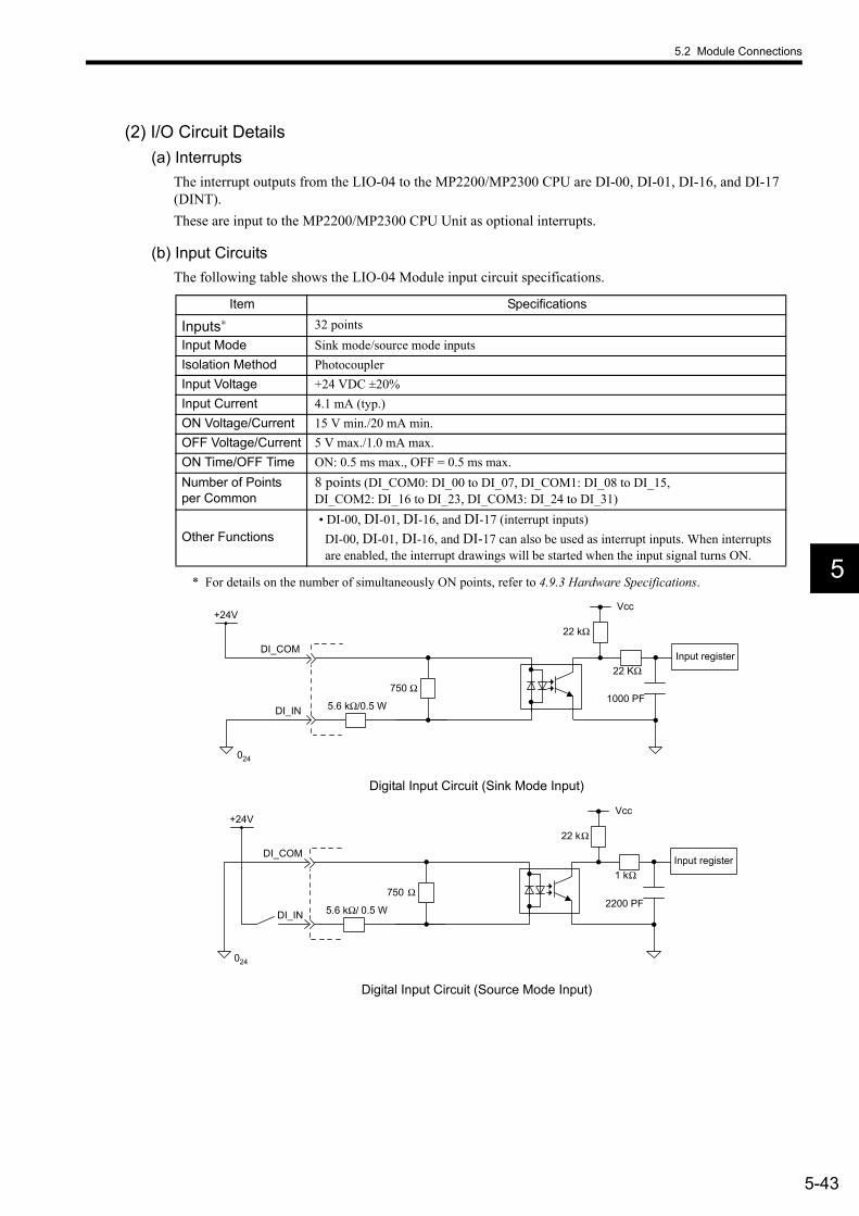
5.2 Module Connections
5-43
5
(2) I/O Circuit Details(a) Interrupts
The interrupt outputs from the LIO-04 to the MP2200/MP2300 CPU are DI-00, DI-01, DI-16, and DI-17 (DINT). These are input to the MP2200/MP2300 CPU Unit as optional interrupts.
(b) Input CircuitsThe following table shows the LIO-04 Module input circuit specifications.
* For details on the number of simultaneously ON points, refer to 4.9.3 Hardware Specifications.
Digital Input Circuit (Sink Mode Input)
Digital Input Circuit (Source Mode Input)
Item Specifications
Inputs∗ 32 pointsInput Mode Sink mode/source mode inputsIsolation Method PhotocouplerInput Voltage +24 VDC ±20%Input Current 4.1 mA (typ.)ON Voltage/Current 15 V min./20 mA min. OFF Voltage/Current 5 V max./1.0 mA max. ON Time/OFF Time ON: 0.5 ms max., OFF = 0.5 ms max. Number of Points per Common
8 points (DI_COM0: DI_00 to DI_07, DI_COM1: DI_08 to DI_15, DI_COM2: DI_16 to DI_23, DI_COM3: DI_24 to DI_31)
Other Functions• DI-00, DI-01, DI-16, and DI-17 (interrupt inputs)DI-00, DI-01, DI-16, and DI-17 can also be used as interrupt inputs. When interrupts are enabled, the interrupt drawings will be started when the input signal turns ON.
5.6 kΩ/0.5 W
Vcc
750 Ω
DI_COM
+24V
DI_IN
22 kΩ
22 KΩ
1000 PF
Input register
024
5.6 kΩ/ 0.5 W
Vcc
750 Ω
DI_COM
+24V
DI_IN
22 kΩ
1 kΩ
2200 PF
Input register
024
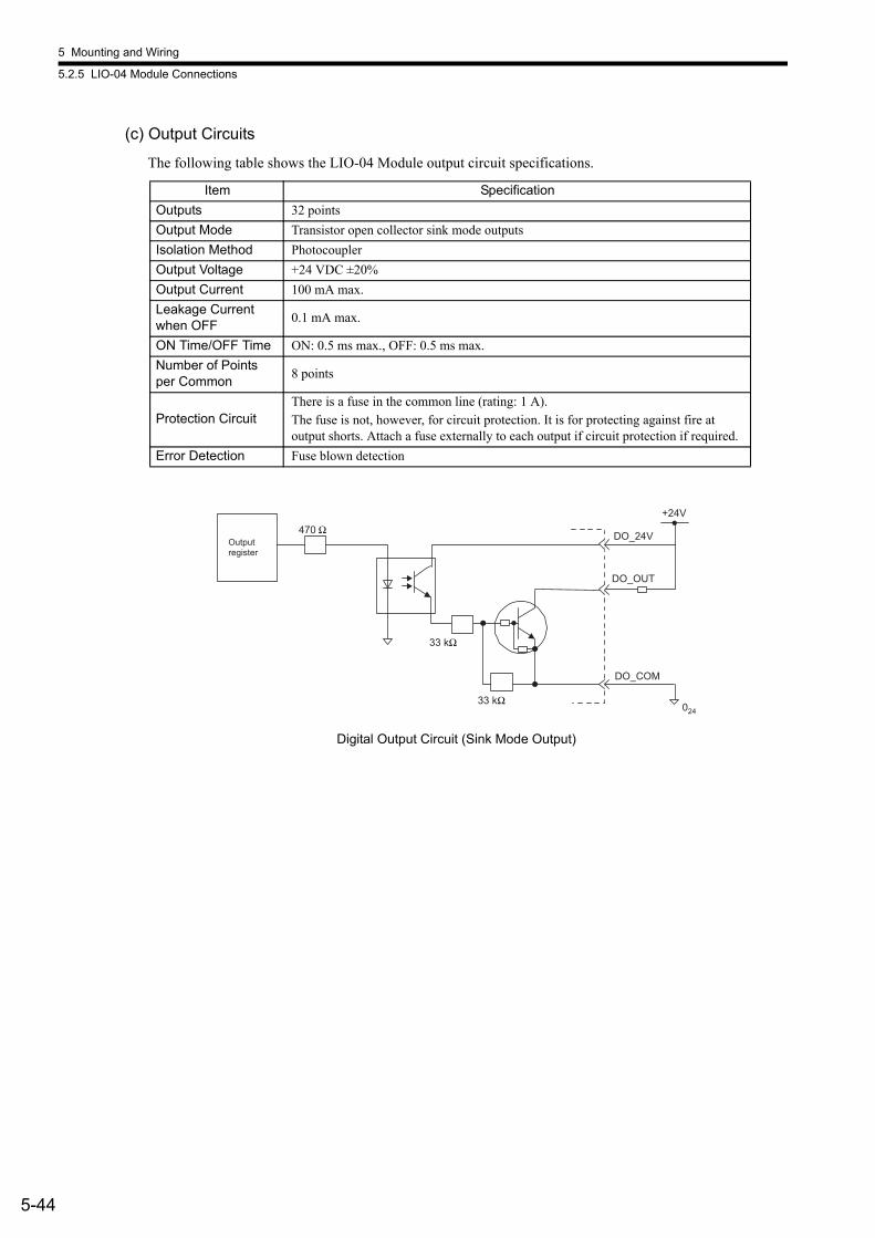
5 Mounting and Wiring
5.2.5 LIO-04 Module Connections
5-44
(c) Output Circuits
The following table shows the LIO-04 Module output circuit specifications.
Digital Output Circuit (Sink Mode Output)
Item SpecificationOutputs 32 pointsOutput Mode Transistor open collector sink mode outputsIsolation Method PhotocouplerOutput Voltage +24 VDC ±20%Output Current 100 mA max.Leakage Current when OFF 0.1 mA max.
ON Time/OFF Time ON: 0.5 ms max., OFF: 0.5 ms max.Number of Points per Common 8 points
Protection CircuitThere is a fuse in the common line (rating: 1 A). The fuse is not, however, for circuit protection. It is for protecting against fire at output shorts. Attach a fuse externally to each output if circuit protection if required.
Error Detection Fuse blown detection
470 Ω
33 kΩ
33 kΩ 024
DO_24VOutputregister
DO_OUT
DO_COM
+24V
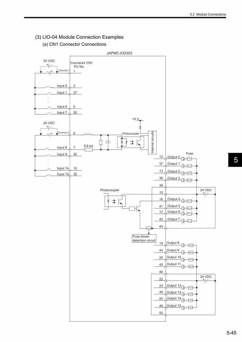
5.2 Module Connections
5-45
5
(3) LIO-04 Module Connection Examples(a) CN1 Connector Connections
+ -
+-
24 VDC
Inte
rnal
circ
uits
+5 V
5.6 kΩ
.
.
.
JAPMC-IO2303
Photocoupler
Fuse blown detection circuit
38
12
13
39
15
41
17
42
16 L
LL
L
L
24 VDC+ -
43
37 L
Output 0
45
19
20
46
22
24
49
23 L
L
L
L
24 VDC
L50
44 L
L
Input 0
Input 1
Input 6
Input 7
.
.
.
+ −
+−
24 VDC
+ -
Photocoupler
L
L
48 L
6
7
32
10
35
1
2
27
5
30
Output 1
Output 2
Output 4
Output 5
Output 6
Output 7
Output 3
Output 12
Output 14
Output 15
Output 13
Output 8
Output 9
Output 10
Output 11
Connector CN1Pin No.
Common 1
Common 2
Input 8
Input 9
Input 14
Input 15
Fuse

5 Mounting and Wiring
5.2.5 LIO-04 Module Connections
5-46
(b) CN2 Connector Connections
+ −
+−
24 VDC
Inte
rnal
circ
uits
+5V
5.6 kΩ
.
.
.
JAPMC-IO2303
Photocoupler
Fuse blown detection circuit
38
12
13
39
15
41
17
42
16 L
LL
L
L
24 VDC+ −
43
37 L
45
19
20
46
22
24
49
23 L
L
L
L
24 VDC
L50
44 L
L
.
.
.
+ −
+−
24 VDC
+ −
Photocoupler
L
L
48 L
6
7
32
10
35
1
2
27
5
30
Output 16
Output 17
Output 18
Output 20
Output 21
Output 22
Output 23
Output 19
Input 16
Output 24
Output 25
Output 26
Output 28
Output 30
Output 31
Output 27
Output 29
Input 17
Input 22
Input 23
Input 24
Input 25
Input 30
Input 31
Common 3
Common 4
Connector CN2Pin No.
Fuse
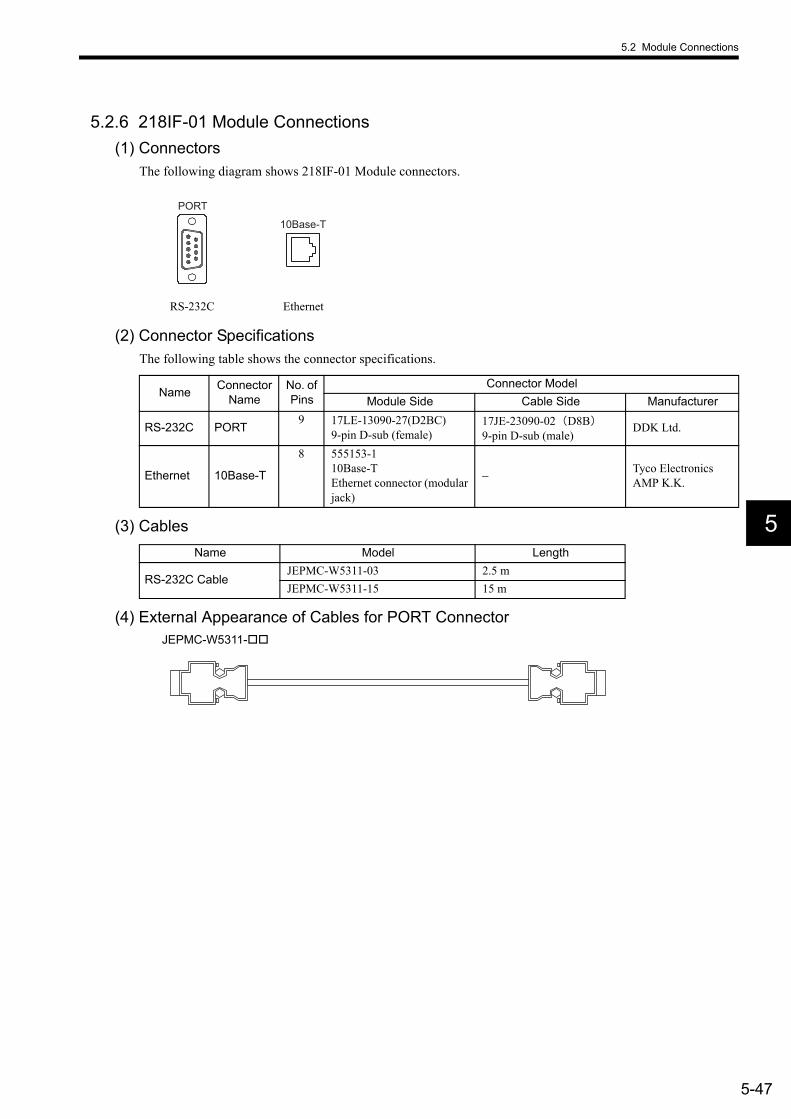
5.2 Module Connections
5-47
5
5.2.6 218IF-01 Module Connections(1) Connectors
The following diagram shows 218IF-01 Module connectors.
(2) Connector SpecificationsThe following table shows the connector specifications.
(3) Cables
(4) External Appearance of Cables for PORT ConnectorJEPMC-W5311-
RS-232C Ethernet
PORT
10Base-T
Name Connector Name
No. of Pins
Connector ModelModule Side Cable Side Manufacturer
RS-232C PORT 9 17LE-13090-27(D2BC)9-pin D-sub (female)
17JE-23090-02(D8B)9-pin D-sub (male)
DDK Ltd.
Ethernet 10Base-T
8 555153-110Base-TEthernet connector (modular jack)
− Tyco Electronics AMP K.K.
Name Model Length
RS-232C CableJEPMC-W5311-03 2.5 mJEPMC-W5311-15 15 m

5 Mounting and Wiring
5.2.6 218IF-01 Module Connections
5-48
(5) Connector Pin Arrangement(a) PORT Connector
The PORT connector is used to connect the MP2200 to computers and HMI devices via an RS-232C connec-tion.
(b) Ethernet Connector (10Base-T)The Ethernet connector is used to connect the MP2200 to computers and HMI devices via an Ethernet (10Base-T) connection.
(6) Module Connection Examples(a) PORT Connector Connections
Pin Num-ber
Signal Name Description
Pin Num-ber
Signal Name Description
1 FG Frame ground 6 − −2 SD Send data 7 SG Signal ground (0 V)3 RD Receive data 8 − −4 RS Request to send 9 ER Data terminal ready5 CS Clear to send − − −
Pin Num-ber
Signal Name Description
1 TXD+ Transmission data +2 TXD− Transmission data −3 RXD+ Reception data +4 − −5 − −6 RXD− Reception data −7 − −8 − −
MP2200 218IF-01
MP2200 MBU-01 CPU-01 SVB-01218IF-01
CN1
CN2
100/200V
BATTEY
POWER
AC
PORT
10Base-T
POWER
M- /
RS-232C (15 m max.)
Opt
ional
Mod
ule
Opt
ional
Mod
ule

5.2 Module Connections
5-49
5
The following tables show the PORT connector connections based on the device to be connected.
ÅD
Table 5.2 For 25-pin D-sub Remote StationsMP2200
(PORT Connector)Cable Connection and Signal
DirectionRemote Station (25-pin D-sub)
Signal Name Pin No. Pin No. Signal
NameFG 1 1 FGSD (TXD) 2 2 SD (TXD)RD (RXD) 3 3 RD (RXD)RS (RTS) 4 4 RS (RTS)CS (CTS) 5 5 CS (CTS)− 6 6 DSR (DR)SG (GND) 7 7 SG (GND)− 8 8 CD
ER (DTR) 9 20 DTR (ER)
Table 5.3 For 9-pin D-sub Remote Station Meeting Yaskawa Specifications
MP2200 (PORT Connector)
Cable Connection and Signal Direction
Remote Station (9-pin D-sub)
(Yaskawa Specifications)Signal Name Pin No. Pin No. Signal
NameFG 1 1 FGSD (TXD) 2 2 SD (TXD)RD (RXD) 3 3 RD (RXD)RS (RTS) 4 4 RS (RTS)CS (CTS) 5 5 CS (CTS)− 6 6 DR (DSR)SG (GND) 7 7 SG (GNDÅ)− 8 8 CD
ER (DTR) 9 9 ER (DTR)
Table 5.4 For DOS Computer Remote Stations
MP2200 (PORT Connector)
Cable Connection and Signal Direction
DOS Computer (9-pin D-sub Male)
Signal Name Pin No. Pin No. Signal
NameFG 1 1 FGSD (TXD) 2 2 RD (RXD)RD (RXD) 3 3 SD (TXD)RS (RTS) 4 4 ER (DTR)CS (CTS) 5 5 SG (GND)− 6 6 DR (DSR)SG (GND) 7 7 RSÅ (RTS)− 8 8 CS (CTS)
ER (DTR) 9 9 −

5 Mounting and Wiring
5.2.6 218IF-01 Module Connections
5-50
(b) Ethernet ConnectionsThis section explains connections to the Ethernet using 10Base-T.The maximum length between the end nodes is 500 m with 10Base-T connections.• Connection Example 1
• Connection Example 2
HUB HUB
100 m 100 m
100 m 100 m
100 m 100 m 100 m
100 m
10Base-T
MP2200 218IF-01
MP2200 MBU-01 CPU-01 SVB-01218IF-01
CN1
CN2
100/200V
BATTEY
POWER
AC
PORT
10Base-T
POWER
M- /
Repeater
Other station
Repeater
Other station Other station
Other station
Opt
ional
Mod
ule
Opt
ional
Mod
ule
MP2200 218IF-01
MP2200 MBU-01 CPU-01 SVB-01218IF-01
CN1
CN2
100/200V
BATTEY
POWER
AC
PORT
10Base-T
POWER
M- /
10Base-T (cross cable: 100 m max.)
Opt
ional
Mod
ule
Opt
ional
Mod
ule

5.2 Module Connections
5-51
5
5.2.7 217IF-01 Module Connections(1) Connectors
The following diagram shows 217IF-01 Module connectors.
(2) Connector SpecificationsThe following table shows the connector specifications.
(3) Cables
(4) External Appearance of Cables for PORT ConnectorJEPMC-W5311-
RS-232C RS-422/485
PORT RS422/485
Name Connector Name
No. of Pins
Connector ModelModule Side Cable Side Manufacturer
RS-232C PORT 9 17LE-13090-27 (D2BC)9-pin D-sub (female)
17JE-23090-02(D8B)9-pin D-sub (male)
DDK Ltd.
RS-422/485 port
RS-422/485
1410214-52A2JL connector
10114-3000VE connector10314-52A0-008 shell
Sumitomo 3M Limited.
Name Model Length
RS-232C CableJEPMC-W5311-03 2.5 mJEPMC-W5311-15 15 m

5 Mounting and Wiring
5.2.7 217IF-01 Module Connections
5-52
(5) Connector Pin Arrangement(a) PORT Connector
The PORT connector is used to connect the MP2200 to computers and HMI devices via an RS-232C connec-tion.
(b) RS-422/485 ConnectorThe RS-422/485 connector is used to connect the MP2200 to computers and HMI devices via an RS-422/485 connection.
Note: A terminator has been included, as shown in the following diagram. If you need to add a terminator, connect RXR to RX (−), and TXR to TX (−). Leave RXR and TXR open if not adding a terminator.
• Always keep the communication cable separate from the drive, control, power supply, and other transmis-sion systems.
• The maximum length of RS-422/485 cable is 300 m. Keep all cables as short as possible.• The 217IF-01 Module RS-422/485 interface is not an isolated system. Noise from connected terminals may
cause malfunctions. If malfunctions occur, use a shielded cable, modem, or other measure to reduce noise.• For RS-422 connections, add a terminator to the reception terminal if required.• For RS-485 connections, add a terminator to the nodes at both ends of the transmission line.
Pin Num-ber
Signal Name Description
Pin Num-ber
Signal Name Description
1 FG Frame ground 6 − −2 SD Send data 7 SG Signal ground (0 V)3 RD Receive data 8 − −4 RS Request to send 9 ER Data terminal ready5 CS Clear to send − − −
Pin Num-ber
Signal Name Description
Pin Num-ber
Signal Name Description
1 TX+ Transmission data + 8 TX+ Transmission data +2 TX− Transmission data − 9 TX− Transmission data −3 RX+ Reception data + 10 RX+ Reception data +
4 RX− Reception data − 11 TXR Transmission data ter-minator
5 − − 12 − −6 RX− Reception data - 13 VCC Power supply (+5 V)
7 RXR Reception data termi-nator 14 GND Ground
RS422/485
RXR
RX (+)
RX (−)
TXR
TX (+)
TX (−)
7
3, 10
4, 6
11
1, 8
2, 9
Terminator
IMPORTANT

5.2 Module Connections
5-53
5
(6) Module Connection Examples(a) PORT Connector Connections
Refer to (a) PORT Connector Connections under (6) Module Connection Examples in 5.2.6 218IF-01 Mod-ule Connections for information on PORT connector connections.
(b) RS-422/485 Connections• RS-422 Wiring
MP2200 MBU-01 CPU-01 218IF-01
100/200V
BATTEY
POWER
AC
PORT
10Base-T
POWER
217IF-01
PORT
RS422/465
MP2200 217IF-01
Opt
ional
Mod
ule
Opt
ional
Mod
ule
To controller or other terminal
1
2
11
3
4
7
14
RS-422/485
3 RX+
4 RX−
7 RXR
1 TX+
2 TX−
11 TXR
14 GND
FG
TX+
TX−
TXR
RX +
RX−
RXR
GND
RS-422/485
1
2
11
3
4
7
14
RS-422/485
TX+
TX−
TXR
RX +
RX−
RXR
GND
Connector shell
Connector shell
Connector shell
Remote Station
The wiring when connecting to another 217IF-01 is shown in the following diagram.
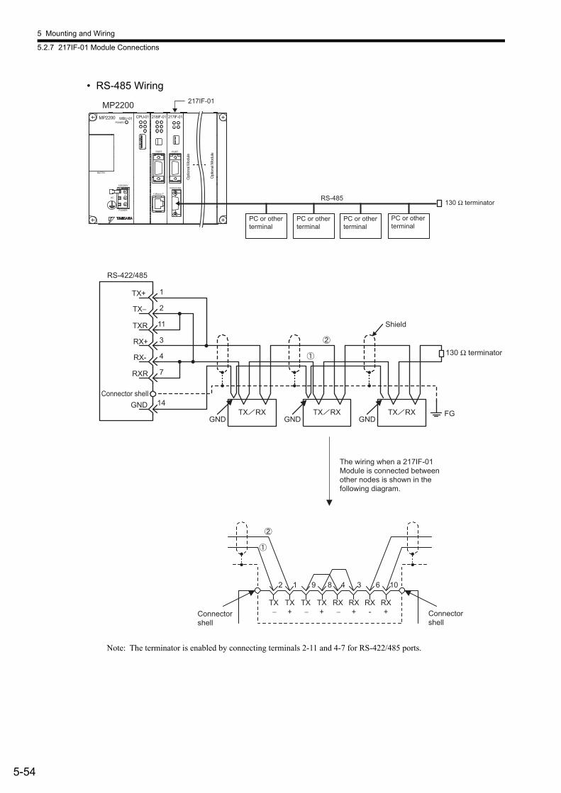
5 Mounting and Wiring
5.2.7 217IF-01 Module Connections
5-54
• RS-485 Wiring
Note: The terminator is enabled by connecting terminals 2-11 and 4-7 for RS-422/485 ports.
RS-485
MP2200 MBU-01 CPU-01 218IF-01
100/200V
BATTEY
POWER
AC
PORT
10Base-T
POWER
217IF-01
PORT
RS422/465
MP2200 217IF-01
130 Ω terminatorO
ption
al M
odule
Opt
ional
Mod
ule
PC or other terminal
PC or other terminal
PC or other terminal
PC or other terminal
TX RX TX RXTX RX
1TX+
2TX−
11
3RX+
4RX-
7RXR
14GNDFG
TX−
TX+
RX−
RX+
9 8 4 3
GND GND GND
TX−
TX+
2 1
RX-
RX+
6 10
TXR
RS-422/485
Connector shell
Shield
130 Ω terminator
Connector shell
Connector shell
The wiring when a 217IF-01 Module is connected between other nodes is shown in the following diagram.
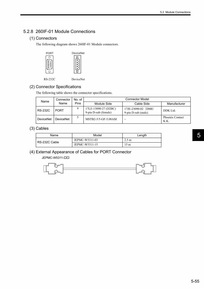
5.2 Module Connections
5-55
5
5.2.8 260IF-01 Module Connections(1) Connectors
The following diagram shows 260IF-01 Module connectors.
(2) Connector SpecificationsThe following table shows the connector specifications.
(3) Cables
(4) External Appearance of Cables for PORT ConnectorJEPMC-W5311-
RS-232C DeviceNet
PORT DeviceNet
Name Connector Name
No. of Pins
Connector ModelModule Side Cable Side Manufacturer
RS-232C PORT 9 17LE-13090-27 (D2BC)9-pin D-sub (female)
17JE-23090-02(D8B)9-pin D-sub (male)
DDK Ltd.
DeviceNet DeviceNet 5 MSTB2-5/5-GF-5.08AM − Phoenix Contact K.K.
Name Model Length
RS-232C CableJEPMC-W5311-03 2.5 mJEPMC-W5311-15 15 m
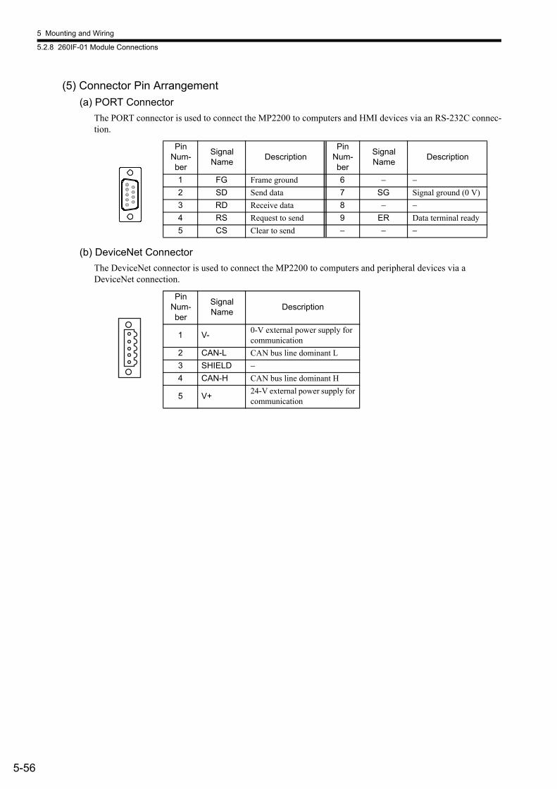
5 Mounting and Wiring
5.2.8 260IF-01 Module Connections
5-56
(5) Connector Pin Arrangement(a) PORT Connector
The PORT connector is used to connect the MP2200 to computers and HMI devices via an RS-232C connec-tion.
(b) DeviceNet ConnectorThe DeviceNet connector is used to connect the MP2200 to computers and peripheral devices via a DeviceNet connection.
Pin Num-ber
Signal Name Description
Pin Num-ber
Signal Name Description
1 FG Frame ground 6 − −2 SD Send data 7 SG Signal ground (0 V)3 RD Receive data 8 − −4 RS Request to send 9 ER Data terminal ready5 CS Clear to send − − −
Pin Num-ber
Signal Name Description
1 V- 0-V external power supply for communication
2 CAN-L CAN bus line dominant L3 SHIELD −4 CAN-H CAN bus line dominant H
5 V+ 24-V external power supply for communication
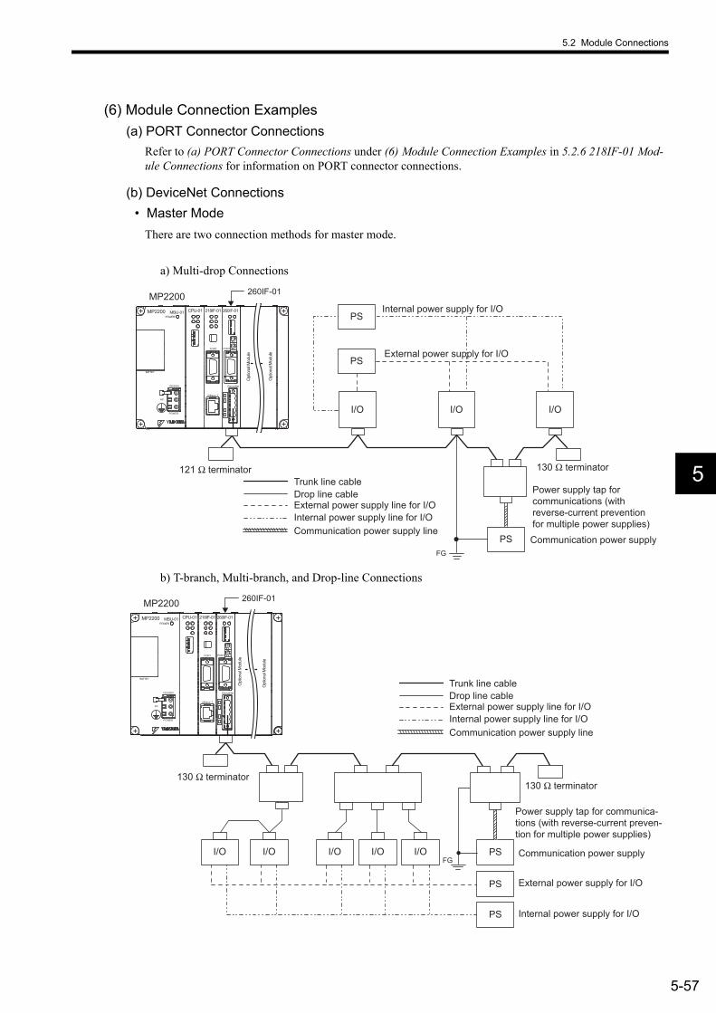
5.2 Module Connections
5-57
5
(6) Module Connection Examples(a) PORT Connector Connections
Refer to (a) PORT Connector Connections under (6) Module Connection Examples in 5.2.6 218IF-01 Mod-ule Connections for information on PORT connector connections.
(b) DeviceNet Connections• Master Mode
There are two connection methods for master mode.
a) Multi-drop Connections
b) T-branch, Multi-branch, and Drop-line Connections
I/O
PS
I/O I/O
FG
PS
PS
MP2200 MBU-01 CPU-01 218IF-01
100/200V
BATTEY
POWER
AC
PORT
10Base-T
POWER
260IF-01
DeviceNet
PORT
MP2200 260IF-01
Trunk line cable Drop line cable External power supply line for I/O Internal power supply line for I/O Communication power supply line
Communication power supply
External power supply for I/O
Internal power supply for I/O
Opt
ional
Mod
ule
Opt
ional
Mod
ule
121 Ω terminator 130 Ω terminator
Power supply tap for communications (with reverse-current prevention for multiple power supplies)
FG
PS
PS
PSI/O I/O I/O I/O I/O
MP2200 MBU-01 CPU-01 218IF-01
100/200V
BATTEY
POWER
AC
PORT
10Base-T
POWER
260IF-01
DeviceNet
PORT
MP2200 260IF-01
Communication power supply
External power supply for I/O
Internal power supply for I/O
Trunk line cable Drop line cable External power supply line for I/O Internal power supply line for I/O Communication power supply line
Opt
ional
Mod
ule
Opt
ional
Mod
ule
130 Ω terminator 130 Ω terminator
Power supply tap for communica-tions (with reverse-current preven-tion for multiple power supplies)

5 Mounting and Wiring
5.2.9 261IF-01 Module Connections
5-58
• Slave ModeThe following diagram shows the system configuration for slave mode.
5.2.9 261IF-01 Module Connections(1) Connectors
The following diagram shows 261IF-01 Module connectors.
(2) Connector SpecificationsThe following table shows the connector specifications.
(3) Cables
(4) External Appearance of Cables for PORT ConnectorJEPMC-W5311-
PSFG
PS
PS
I/O I/O
MP2300260IF-01
MP2200 MBU-01 CPU-01 218IF-01
100/200V
BATTEY
POWER
AC
PORT
10Base-T
POWER
260IF-01
DeviceNet
PORT
MP2200 260IF-01
Trunk line cable Drop line cable External power supply line for I/O Internal power supply line for I/O Communication power supply line
External power supply for I/O
Internal power supply for I/O Slave Mode
Opt
ional
Mod
ule
Opt
ional
Mod
ule
130 Ω terminator 130 Ω terminator
Power supply tap for commu-nications (with reverse-cur-rent prevention for multiple power supplies)
Communication power supply
RS-232C PROFIBUS
PORT PROFIBUS
Name Connector Name
No. of Pins
Connector ModelModule Side Cable Side Manufacturer
RS-232C PORT 9 17LE-13090-27 (D2BC) 9-pin D-sub (female)
17JE-23090-02(D8B)9-pin D-sub (male)
DDK Ltd.
PROFIBUS PROFIBUS 9 17LE-13090-27 (D33C)9-pin D-sub (female) − DDK Ltd.
Name Model Length
RS-232C CableJEPMC-W5311-03 2.5 mJEPMC-W5311-15 15 m

5.2 Module Connections
5-59
5
(5) Connector Pin Arrangement(a) PORT Connector
The PORT connector is used to connect the MP2200 to computers and HMI devices via an RS-232C connec-tion.
(b) PROFIBUS ConnectorThe PROFIBUS connector is used to connect to masters via a PROFIBUS connection.
Pin Num-ber
Signal Name Description
Pin Num-ber
Signal Name Description
1 FG Frame ground 6 − −2 SD Send data 7 SG Signal ground (0 V)3 RD Receive data 8 − −4 RS Request to send 9 ER Data terminal ready5 CS Clear to send − − −
Pin Num-ber
Signal Name Description
1 − −2 − −3 TXD/RDX+ Transmission and reception (+)4 RTS Request to send5 GND Ground6 +5V External power supply7 − −8 TXD/RDX- Transmission and reception data -9 − −

5 Mounting and Wiring
5.2.9 261IF-01 Module Connections
5-60
(6) Module Connection Examples(a) PORT Connector Connections
Refer to (a) PORT Connector Connections under (6) Module Connection Examples in 5.2.6 218IF-01 Mod-ule Connections for information on PORT connector connections.
(b) PROFIBUS ConnectionsThe 261IF-01 Module supports only slave mode. The slave address can be set between 1 and 64.
261IF-01
MP2200 MBU-01 CPU-01 218IF-01
100/200V
BATTEY
POWER
AC
PORT
10Base-T
POWER
261IF-01
MP2200
PROFIBUS
Inverter SERVOPACK Machine-side I/O signals
PROFIBUS-DP Master (Class 1 Master) O
ption
al M
odule
Opt
ional
Mod
ule

5.2 Module Connections
5-61
5
5.2.10 EXIOIF Module Connections(1) Connectors
The following diagram shows EXIOIF Module connectors.
The following diagram shows how to connect the external I/O connectors.
Note: Attached the enclosed dust caps to the unused connectors (1) in the above figure.
These connectors are use to expand the number of mounting bases to a maximum of four racks. They are connected using the following cables. • JEPMC-W2091-
CN2OUT
CN1IN
EXIOIF
EXIOIF
EXIOIF
EXIOIF
CN1IN
CN2OUT
CN1IN
CN2OUT
CN1IN
CN2OUT
CN1IN
CN2OUT
Rack 1
Rack 4
Rack 3
Rack 2

5 Mounting and Wiring
5.2.10 EXIOIF Module Connections
5-62
(2) Cables
Note: 1. The total cable length when adding expansion racks is 6.0 m. Connect the shield to the connector shell. 2. Connection method: 1:13. Cable Specifications: Shielded cable, equivalent to UL20276, 0.08 mm2 (AWG28), two ferrite cores
attached
(3) Cable Appearance
Name Model Length
Connection Cables (with both connectors)
JEPMC-W2091-A5 0.5 mJEPMC-W2091-01 1.0 mJEPMC-W2091-2A5 2.5 m
6-1
6
6Basic System Operation
This chapter explains the basic operation of the MP2200 system.
6.1 Operating Mode - - - - - - - - - - - - - - - - - - - - - - - - - - - - - - - - - - - - - - - - - - 6-26.1.1 Online Operating Mode - - - - - - - - - - - - - - - - - - - - - - - - - - - - - - - - - - - - - - - - - - - - - 6-26.1.2 Offline Stop Mode - - - - - - - - - - - - - - - - - - - - - - - - - - - - - - - - - - - - - - - - - - - - - - - - - 6-2
6.2 Startup Sequence and Basic Operation - - - - - - - - - - - - - - - - - - - - - - - - - 6-36.2.1 DIP Switch Settings - - - - - - - - - - - - - - - - - - - - - - - - - - - - - - - - - - - - - - - - - - - - - - - - 6-36.2.2 Indicator Patterns - - - - - - - - - - - - - - - - - - - - - - - - - - - - - - - - - - - - - - - - - - - - - - - - - 6-46.2.3 Startup Sequence - - - - - - - - - - - - - - - - - - - - - - - - - - - - - - - - - - - - - - - - - - - - - - - - - 6-5
6.3 User Program - - - - - - - - - - - - - - - - - - - - - - - - - - - - - - - - - - - - - - - - - - - - 6-76.3.1 Drawings (DWGs) - - - - - - - - - - - - - - - - - - - - - - - - - - - - - - - - - - - - - - - - - - - - - - - - - 6-76.3.2 Execution Control of Drawings - - - - - - - - - - - - - - - - - - - - - - - - - - - - - - - - - - - - - - - - 6-86.3.3 Motion Programs - - - - - - - - - - - - - - - - - - - - - - - - - - - - - - - - - - - - - - - - - - - - - - - - - 6-116.3.4 Functions - - - - - - - - - - - - - - - - - - - - - - - - - - - - - - - - - - - - - - - - - - - - - - - - - - - - - - 6-19
6.4 Registers - - - - - - - - - - - - - - - - - - - - - - - - - - - - - - - - - - - - - - - - - - - - - - 6-206.4.1 Data Types - - - - - - - - - - - - - - - - - - - - - - - - - - - - - - - - - - - - - - - - - - - - - - - - - - - - - 6-206.4.2 Types of Registers - - - - - - - - - - - - - - - - - - - - - - - - - - - - - - - - - - - - - - - - - - - - - - - - 6-236.4.3 Register Designation Methods - - - - - - - - - - - - - - - - - - - - - - - - - - - - - - - - - - - - - - - 6-266.4.4 Subscripts i and j - - - - - - - - - - - - - - - - - - - - - - - - - - - - - - - - - - - - - - - - - - - - - - - - - 6-27
6.5 Self-configuration - - - - - - - - - - - - - - - - - - - - - - - - - - - - - - - - - - - - - - - - 6-296.5.1 Overview of Self-configuration - - - - - - - - - - - - - - - - - - - - - - - - - - - - - - - - - - - - - - - 6-296.5.2 SVB-01 Modules - - - - - - - - - - - - - - - - - - - - - - - - - - - - - - - - - - - - - - - - - - - - - - - - - 6-306.5.3 SVA-01 Modules - - - - - - - - - - - - - - - - - - - - - - - - - - - - - - - - - - - - - - - - - - - - - - - - - 6-396.5.4 LIO-01 Modules - - - - - - - - - - - - - - - - - - - - - - - - - - - - - - - - - - - - - - - - - - - - - - - - - 6-406.5.5 LIO-02 Modules - - - - - - - - - - - - - - - - - - - - - - - - - - - - - - - - - - - - - - - - - - - - - - - - - 6-416.5.6 LIO-04 Modules - - - - - - - - - - - - - - - - - - - - - - - - - - - - - - - - - - - - - - - - - - - - - - - - - 6-426.5.7 218IF-01 Modules - - - - - - - - - - - - - - - - - - - - - - - - - - - - - - - - - - - - - - - - - - - - - - - - 6-436.5.8 217IF-01 Modules - - - - - - - - - - - - - - - - - - - - - - - - - - - - - - - - - - - - - - - - - - - - - - - - 6-446.5.9 260IF-01 Modules - - - - - - - - - - - - - - - - - - - - - - - - - - - - - - - - - - - - - - - - - - - - - - - - 6-466.5.10 261IF-01 Modules - - - - - - - - - - - - - - - - - - - - - - - - - - - - - - - - - - - - - - - - - - - - - - - 6-47
6.6 Setting and Changing User-defined Files or Data - - - - - - - - - - - - - - - - - 6-486.6.1 Saving User-defined Files or Data - - - - - - - - - - - - - - - - - - - - - - - - - - - - - - - - - - - - - 6-486.6.2 Setting and Changing the Scan Times - - - - - - - - - - - - - - - - - - - - - - - - - - - - - - - - - - 6-486.6.3 Setting and Changing the Module Configuration Definition - - - - - - - - - - - - - - - - - - - 6-49
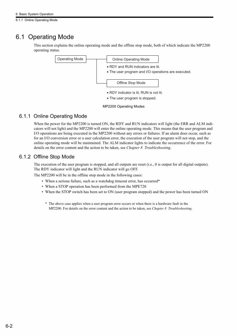
6 Basic System Operation
6.1.1 Online Operating Mode
6-2
6.1 Operating ModeThis section explains the online operating mode and the offline stop mode, both of which indicate the MP2200 operating status.
MP2200 Operating Modes
6.1.1 Online Operating ModeWhen the power for the MP2200 is turned ON, the RDY and RUN indicators will light (the ERR and ALM indi-cators will not light) and the MP2200 will enter the online operating mode. This means that the user program and I/O operations are being executed in the MP2200 without any errors or failures. If an alarm does occur, such as for an I/O conversion error or a user calculation error, the execution of the user program will not stop, and the online operating mode will be maintained. The ALM indicator lights to indicate the occurrence of the error. For details on the error content and the action to be taken, see Chapter 8 Troubleshooting.
6.1.2 Offline Stop ModeThe execution of the user program is stopped, and all outputs are reset (i.e., 0 is output for all digital outputs). The RDY indicator will light and the RUN indicator will go OFF. The MP2200 will be in the offline stop mode in the following cases:
• When a serious failure, such as a watchdog timeout error, has occurred*• When a STOP operation has been performed from the MPE720• When the STOP switch has been set to ON (user program stopped) and the power has been turned ON
* The above case applies when a user program error occurs or when there is a hardware fault in the MP2200. For details on the error content and the action to be taken, see Chapter 8 Troubleshooting.
Operating Mode Online Operating Mode
Offline Stop Mode
• The user program and I/O operations are executed.
• The user program is stopped.
• RDY and RUN indicators are lit.
• RDY indicator is lit, RUN is not lit.
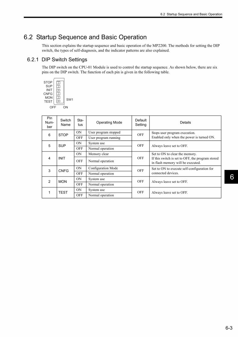
6.2 Startup Sequence and Basic Operation
6-3
6
6.2 Startup Sequence and Basic OperationThis section explains the startup sequence and basic operation of the MP2200. The methods for setting the DIP switch, the types of self-diagnosis, and the indicator patterns are also explained.
6.2.1 DIP Switch SettingsThe DIP switch on the CPU-01 Module is used to control the startup sequence. As shown below, there are six pins on the DIP switch. The function of each pin is given in the following table.
Pin Num-ber
Switch Name
Sta-tus Operating Mode Default
Setting Details
6 STOPON User program stopped
OFF Stops user program execution.Enabled only when the power is turned ON.OFF User program running
5 SUPON System use
OFF Always leave set to OFF.OFF Normal operation
4 INITON Memory clear
OFFSet to ON to clear the memory. If this switch is set to OFF, the program stored in flash memory will be executed.OFF Normal operation
3 CNFGON Configuration Mode
OFF Set to ON to execute self-configuration for connected devices.OFF Normal operation
2 MONON System use
OFF Always leave set to OFF.OFF Normal operation
1 TESTON System use
OFF Always leave set to OFF.OFF Normal operation
SW1
OFF ON
STOPSUPINIT
CNFGMON
TEST

6 Basic System Operation
6.2.2 Indicator Patterns
6-4
6.2.2 Indicator PatternsThe MP2200 makes a number of determinations at startup. If an error is detected, the ERR indicator will blink and the error content will be indicated by the number of times the indicator blinks. When the indicator is blink-ing, the MPE720 cannot be operated. For details on the error content and the action to be taken, see Chapter 7 Maintenance and Inspection and Chapter 8 Troubleshooting. The following table shows the MP2200 indicators.
Note: The symbols under Indicator Name have the following meanings.: Not lit, : Lit, : Blinking, −: Undefined.
Cla
ssifi
catio
n Indicator Name
Indicator Details RemarksRDY RUN ALM ERR BAT
Nor
mal
Hardware reset status−Initializing.
Drawing A executing.
User program stopped (offline stop mode).
This status is entered when STOP operation is per-formed from a switch or the MPE720.
User program executing normally. −
Erro
r
Serious failureThe ERR indicator lights when there is a failure in the CPU.
Number of blinks for software errors:3: Address read error4: Address write error5: FPU error6: Illegal general command error7: Illegal slot command error8: General FPU inhibited error9: Slot FPU inhibited error10: TLB multi-bit error11: LTB read error12: LTB write error13: LTB protection violation (read)14: LTB protection violation (write)15: Initial page write error
The ERR indicator blinks when there is an error.
Number of blinks for hardware errors: 2: RAM diagnosis error3: ROM diagnosis error4: CPU function diagnosis error5: FPU function diagnosis error
The ALM and ERR indica-tors blink when there is a self-diagnosis failure.
War
ning
− − − − Battery alarmThe BAT indicator lights when the battery voltage drops.
Operation errorI/O error
The ALM indicator lights when a calculation or I/O error is detected.

6.2 Startup Sequence and Basic Operation
6-5
6
6.2.3 Startup SequenceA basic outline of the startup sequence and basic operation of the MP2200 is shown below.
ON
OFF
Turn ON the power.
Memory clear switch check
Startup self-diagnosis
RDY indicator lit
Memory clear
Flash
Copied from FLASH to RAM
STOP switch check
Watchdog timer start
DWG.A execution (ladder program)
Priority High
Online self-diagnosis
Background Ladder Program
Interrupt signal
DWG.I execution
Completed once.
Input
DWG.H execution
Output
High-speed scan
Input
DWG.L execution
Output
Low-speed scan
Normal operation
Self-configuration executing
Configuration Mode switch setting
Configuration Mode
RUN indicator lit
User program stopped

6 Basic System Operation
6.2.3 Startup Sequence
6-6
(1) Startup Self-diagnosisThe following operations are provided for startup self-diagnosis:
• Memory (RAM) read/write diagnosis• System program (ROM) diagnosis• Main processor (CPU) function diagnosis• Floating point unit (FPU) function diagnosis
If an error occurs in the diagnosis, the ALM and ERR indicators will blink the specified number of times.
(2) Online Self-diagnosisThe following operations are provided for online self-diagnosis:
• System program (ROM) diagnosis• Main processor (CPU) function diagnosis• Floating point unit (FPU) function diagnosis
If an error occurs in the diagnostic result, the ALM and ERR indicators will blink the specified number of times.
(3) Self-configuration1. Self-configuration eliminates the need to make settings for Module definitions, making it possible to per-
form startup work easily and quickly for the MP2200 system. Optional Modules are recognized and defi-nition files are generated automatically. For details, refer to 6.5 Self-configuration.
2. The RUN indicator blinks during execution of self-configuration.
(4) Operation StartIf the Stop Switch is OFF (RUN) or if it is turned OFF (RUN) from ON (STOP), the CPU starts the watchdog timer and then executes DWG.A.The initial scan is executed only after the time for the high-speed or low-speed scan has ended following the completion of DWG.A. System inputs and outputs are executed from the first scan.
(5) Operation StopThe MP2200 stops operating in the following cases:
Cause CountermeasureThe power supply is interrupted.
Turn power OFF and ON.A power failure has occurred.
A fatal error has occurred. Determine the error by the indicator status and turn the power OFF and ON.
A STOP operation has been performed from the MPE720. Perform a RUN operation from the MPE720.
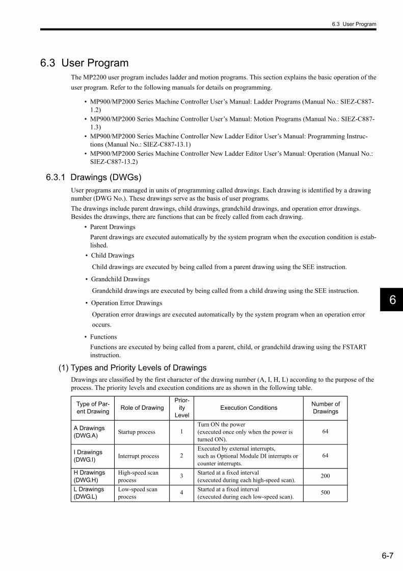
6.3 User Program
6-7
6
6.3 User ProgramThe MP2200 user program includes ladder and motion programs. This section explains the basic operation of theuser program. Refer to the following manuals for details on programming.
• MP900/MP2000 Series Machine Controller User’s Manual: Ladder Programs (Manual No.: SIEZ-C887-1.2)
• MP900/MP2000 Series Machine Controller User’s Manual: Motion Programs (Manual No.: SIEZ-C887-1.3)
• MP900/MP2000 Series Machine Controller New Ladder Editor User’s Manual: Programming Instruc-tions (Manual No.: SIEZ-C887-13.1)
• MP900/MP2000 Series Machine Controller New Ladder Editor User’s Manual: Operation (Manual No.: SIEZ-C887-13.2)
6.3.1 Drawings (DWGs)User programs are managed in units of programming called drawings. Each drawing is identified by a drawing number (DWG No.). These drawings serve as the basis of user programs.The drawings include parent drawings, child drawings, grandchild drawings, and operation error drawings. Besides the drawings, there are functions that can be freely called from each drawing.
• Parent DrawingsParent drawings are executed automatically by the system program when the execution condition is estab-lished.
• Child Drawings
Child drawings are executed by being called from a parent drawing using the SEE instruction.
• Grandchild Drawings
Grandchild drawings are executed by being called from a child drawing using the SEE instruction.
• Operation Error Drawings
Operation error drawings are executed automatically by the system program when an operation error occurs.
• FunctionsFunctions are executed by being called from a parent, child, or grandchild drawing using the FSTART instruction.
(1) Types and Priority Levels of DrawingsDrawings are classified by the first character of the drawing number (A, I, H, L) according to the purpose of the process. The priority levels and execution conditions are as shown in the following table.
Type of Par-ent Drawing Role of Drawing
Prior-ity
LevelExecution Conditions Number of
Drawings
A Drawings (DWG.A) Startup process 1
Turn ON the power(executed once only when the power is turned ON).
64
I Drawings (DWG.I) Interrupt process 2
Executed by external interrupts,such as Optional Module DI interrupts or counter interrupts.
64
H Drawings (DWG.H)
High-speed scan process
3 Started at a fixed interval(executed during each high-speed scan).
200
L Drawings (DWG.L)
Low-speed scan process
4 Started at a fixed interval(executed during each low-speed scan).
500
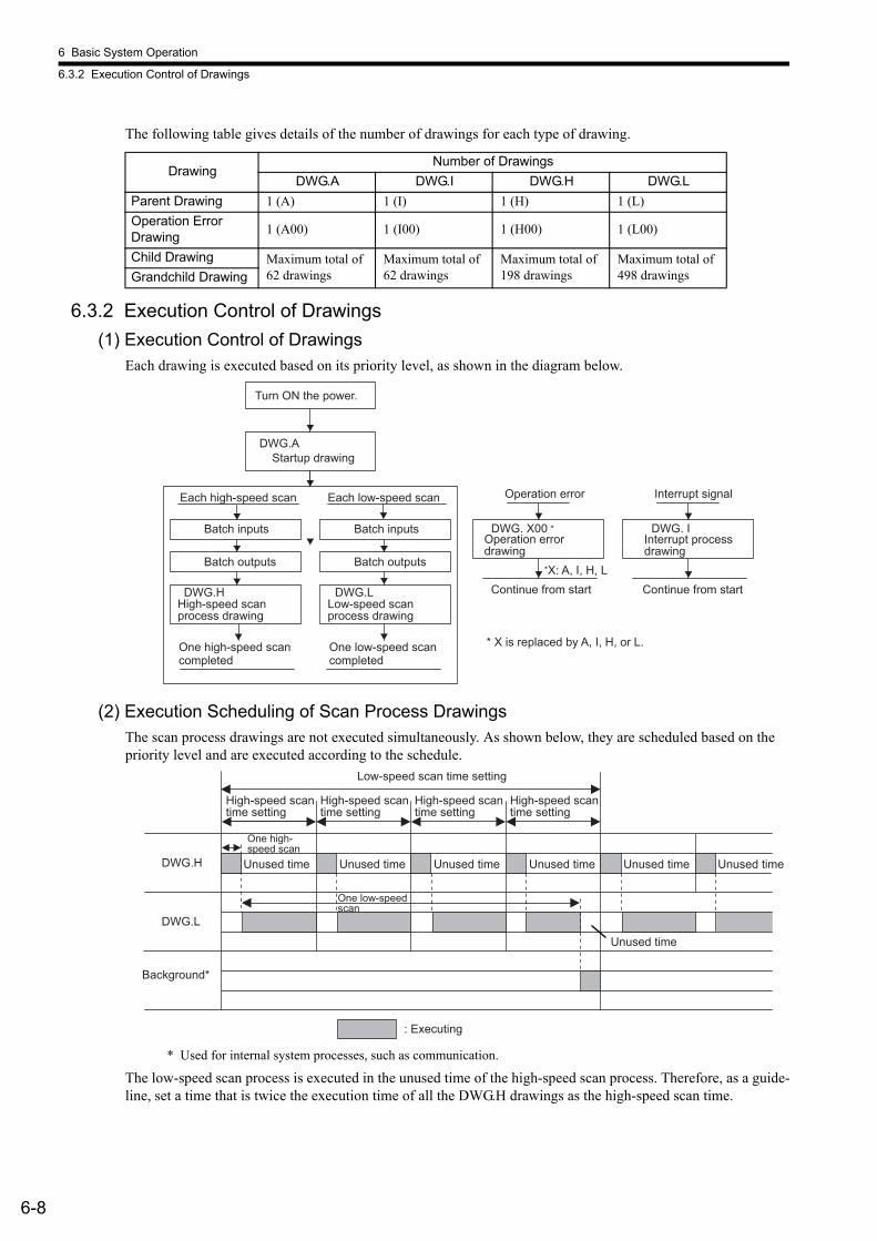
6 Basic System Operation
6.3.2 Execution Control of Drawings
6-8
The following table gives details of the number of drawings for each type of drawing.
6.3.2 Execution Control of Drawings(1) Execution Control of Drawings
Each drawing is executed based on its priority level, as shown in the diagram below.
(2) Execution Scheduling of Scan Process DrawingsThe scan process drawings are not executed simultaneously. As shown below, they are scheduled based on the priority level and are executed according to the schedule.
* Used for internal system processes, such as communication.
The low-speed scan process is executed in the unused time of the high-speed scan process. Therefore, as a guide-line, set a time that is twice the execution time of all the DWG.H drawings as the high-speed scan time.
DrawingNumber of Drawings
DWG.A DWG.I DWG.H DWG.LParent Drawing 1 (A) 1 (I) 1 (H) 1 (L)Operation Error Drawing 1 (A00) 1 (I00) 1 (H00) 1 (L00)
Child Drawing Maximum total of 62 drawings
Maximum total of 62 drawings
Maximum total of 198 drawings
Maximum total of 498 drawingsGrandchild Drawing
DWG.A
DWG.H DWG.L
DWG. X00 DWG. I
*X: A, I, H, L
*
Operation error
Turn ON the power.
Startup drawing
Each high-speed scan Each low-speed scan
Batch inputs Batch inputs
Batch outputs Batch outputs
High-speed scan process drawing
Low-speed scan process drawing
Operation error drawing
Continue from start
Interrupt signal
Interrupt process drawing
Continue from start
One high-speed scan completed
One low-speed scan completed
* X is replaced by A, I, H, or L.
DWG.H
DWG.L
: Executing
High-speed scan time setting
Low-speed scan time setting
Background*
High-speed scan time setting
High-speed scan time setting
High-speed scan time setting
One high-speed scan
Unused time Unused timeUnused timeUnused timeUnused timeUnused time
One low-speed scan
Unused time

6.3 User Program
6-9
6
(3) Hierarchical Arrangement of DrawingsDrawings are arranged in the following order: Parent drawing, child drawings, grandchild drawings. A parent drawing cannot call a child drawing of a different type, and a child drawing cannot call a grandchild drawing of a different type. A parent drawing also cannot directly call a grandchild drawing. A child drawing is called from a parent drawing, and a grandchild drawing is called from that child drawing. This is called the hierarchical arrangement of drawings.Each processing program is prepared with the parent drawing, child drawing, grandchild drawing hierarchy, as shown below.
DWG.X DWG.X01.01DWG.X01
DWG.X01.99
DWG.X01.02
DWG.Xnn
FUNC-064
FUNC-032
FUNC-006
FUNC-001
Parent drawing Child drawing Grandchild drawing User functions
Note: Replace X with A, I, H, or L.
DWG.X YY . ZZ
DWG.X 00
DWG notation:
Grandchild drawing number (01 to 99)
Type of parent drawing (A, I, H, or L)
Child drawing number (01 to 99)
Operation error processing drawing (A, I, H, or L)

6 Basic System Operation
6.3.2 Execution Control of Drawings
6-10
(4) Execution Processing Method of DrawingsDrawings in the hierarchy are executed by the lower-level drawings being called from upper-level drawings. The execution method is shown below, using DWG.A as an example.
Note: 1. A parent drawing is automatically called by the system. The user can execute any child or grand-child drawing by programming an instruction that calls the drawing (the SEE instruction) in a par-ent or child drawing.
2. Functions can be called from any drawing. A function can also be called from a function.3. If an operation error occurs, the operation error drawing corresponding to the drawing will be
called.
FUNC-001
FUNC-001
DWG.A
SEE A01
SEE A02
DEND
DWG.A01
SEE A01.01
SEE A01.02 DEND
DEND
DEND
DENDDEND
DEND
DWG.A02
DWG.A00
DWG.A01.02
DWG.A01.01
FUNC-001
Parent drawing Child drawing Grandchild drawing
Functions
System program starts when the execution condition is established.
System starts automatically
Operation error
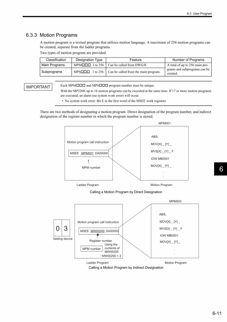
6.3 User Program
6-11
6
6.3.3 Motion ProgramsA motion program is a textual program that utilizes motion language. A maximum of 256 motion programs can be created, separate from the ladder programs.Two types of motion program are provided.
Each MPM and MPS program number must be unique.With the MP2200, up to 16 motion programs can be executed at the same time. If 17 or more motion programs are executed, an alarm (no system work error) will occur.• No system work error: Bit E in the first word of the MSEE work registers
There are two methods of designating a motion program: Direct designation of the program number, and indirect designation of the register number in which the program number is stored.
Calling a Motion Program by Direct Designation
Calling a Motion Program by Indirect Designation
Classification Designation Type Feature Number of ProgramsMain Programs MPM 1 to 256 Can be called from DWG.H A total of up to 256 main pro-
grams and subprograms can be created.Subprograms MPS 1 to 256 Can be called from the main program.
IMPORTANT
MSEE MPM001 DA00000
ABS;
MOV[X] _ [Y] _
MOV[X] _ [Y] _
MVS[X] _ [Y] _ F
IOW MB0001
.
.
MPM001
Motion program call instruction
MPM number
Ladder Program Motion Program
MSEE MW00200 DA000000 3
ABS;
IOW MB0001
.
.
MOV[X] _ [Y] _
MOV[X] _ [Y] _
MVS[X] _ [Y] _ F
∗ MW00200 = 3
MPM003
Motion program call instruction
Ladder Program Motion Program
Setting device
MPM number
Register number Using the contents of MW00200
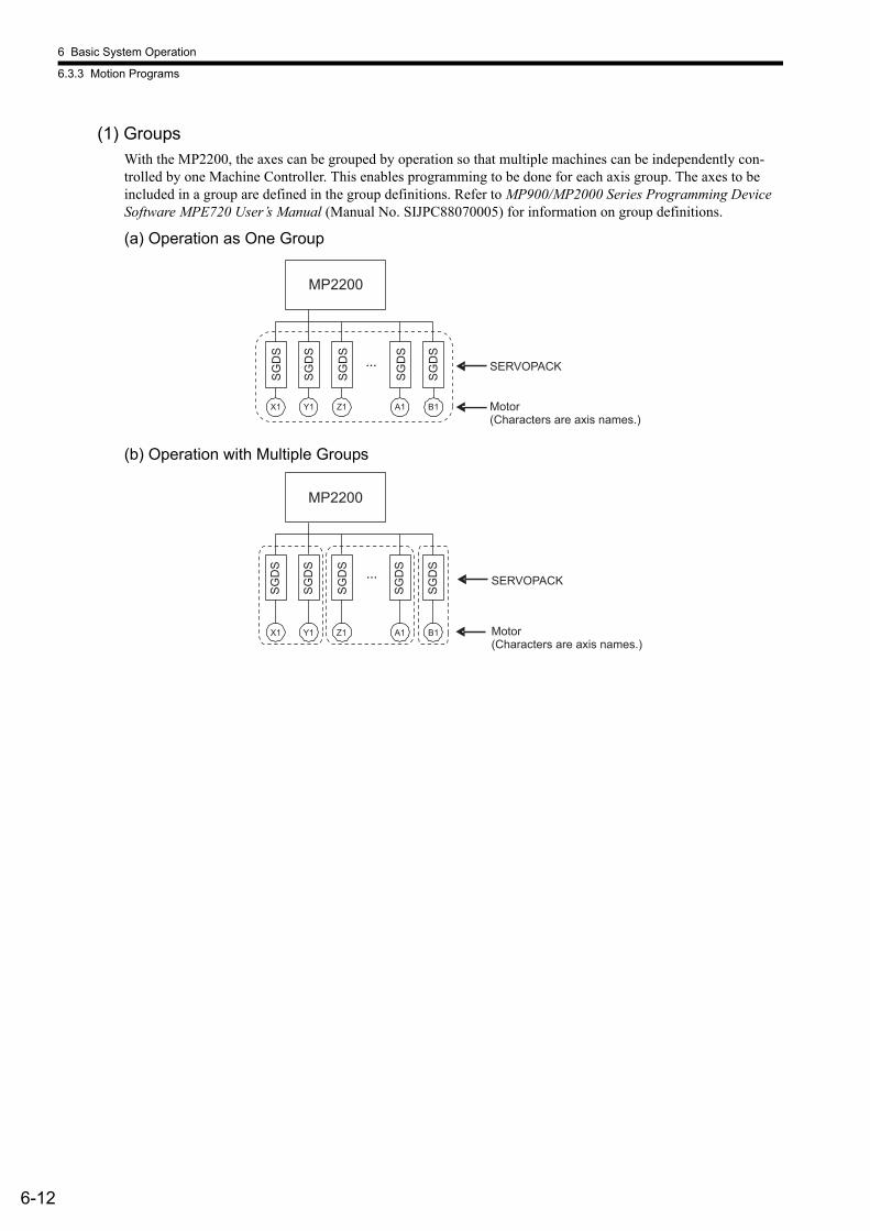
6 Basic System Operation
6.3.3 Motion Programs
6-12
(1) GroupsWith the MP2200, the axes can be grouped by operation so that multiple machines can be independently con-trolled by one Machine Controller. This enables programming to be done for each axis group. The axes to be included in a group are defined in the group definitions. Refer to MP900/MP2000 Series Programming Device Software MPE720 User’s Manual (Manual No. SIJPC88070005) for information on group definitions.
(a) Operation as One Group
(b) Operation with Multiple Groups
MP2200
SGD
S
SGD
S
SGD
S
SGD
S
SGD
S
X1 Y1 Z1 A1 B1
SERVOPACK
Motor (Characters are axis names.)
X1 Y1 Z1 A1 B1
MP2200
SGD
S
SGD
S
SGD
S
SGD
S
SGD
S
SERVOPACK
Motor (Characters are axis names.)

6.3 User Program
6-13
6
(2) Motion Program Execution Processing MethodA motion program must be called from DWG.H using the MSEE instruction. Motion programs can be called from any DWG.H, i.e., from parent, child, and grandchild DWG.H.A motion program execution example is shown below.
In each high-speed scanning cycle, the ladder instructions for DWG.H are executed in the following hierarchical order: Parent drawing - child drawing - grandchild drawing.Motion programs are called in the scanning cycle, but as with ladder programs, all programs cannot necessarily be executed in one scan. Motion programs are executed and controlled by special system motion management functions.
The following points apply to calling motion programs. Call motion programs with care.• More than one motion program with the same number cannot be called using the MSEE instruction.• Subprograms (MPS ) cannot be called using the ladder program MSEE instruction. They can be called only
from within motion programs (MPM and MPS ).• The same subprogram cannot be called from two different locations at the same time.
MSEEMPM001
DWG.H
SEEH01
DEND
DWG.H01
SEE H01.01
END
DEND
END
RETEND
DEND
MPM003
MPS101
DWG.H01.01 MPM001
MPM002MSEE
MPM002
MSEEMPM003
MSEEMPS101
VEL [a1]5000 [b1]..FMX T10000000;IAC T25;IDC T30;MOV [a1]300. [b1]..MVS [a1]200. [b1]..
. . .
Parent drawing Child drawing Grandchild drawing Motion main programs
Subprogram
System program starts when the execution condition is established.
INFO
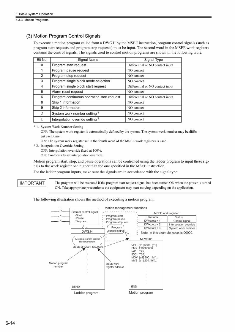
6 Basic System Operation
6.3.3 Motion Programs
6-14
(3) Motion Program Control SignalsTo execute a motion program called from a DWG.H by the MSEE instruction, program control signals (such as program start requests and program stop requests) must be input. The second word in the MSEE work registers contains the control signals. The signals used to control motion programs are shown in the following table.
* 1. System Work Number SettingOFF: The system work register is automatically defined by the system. The system work number may be differ-ent each time.ON: The system work register set in the fourth word of the MSEE work registers is used.
* 2. Interpolation Override SettingOFF: Interpolation override fixed at 100%.ON: Conforms to set interpolation override.
Motion program start, stop, and pause operations can be controlled using the ladder program to input these sig-nals to the work register one higher than the one specified in the MSEE instruction.For the ladder program inputs, make sure the signals are in accordance with the signal type.
The program will be executed if the program start request signal has been turned ON when the power is turned ON. Take appropriate precautions; the equipment may start moving depending on the application.
The following illustration shows the method of executing a motion program.
Bit No. Signal Name Signal Type0 Program start request Differential or NO contact input1 Program pause request NO contact2 Program stop request NO contact3 Program single block mode selection NO contact4 Program single block start request Differential or NO contact input5 Alarm reset request NO contact6 Program continuous operation start request Differential or NO contact input8 Skip 1 information NO contact9 Skip 2 information NO contactD System work number setting*1 NO contact
E Interpolation override setting*2 NO contact
IMPORTANT
DWxxxxxDWxxxxx + 1DWxxxxx + 2DWxxxxx + 3
DWG.H
MSEE MPM001 DA00000
DEND
MPM001
VEL [a1] 5000 [b1]..FMX T10000000;IAC T25;IDC T30;MOV [a1] 300. [b1]..MVS [a1] 200. [b1]..
END
.
.
.
.
.
.
.
.
.
.
.
.
......
External control signal Start Pause Stop, etc.
Program start Program pause Program stop, etc.
MSEE work register Status
Control signal Interpolation override System work number
Motion management functions
Ladder program Motion program
Motion program control ladder program
Program control signal
Motion program number
MSEE work register address
Note: In this example xxxxx is 00000.
6.3 User Program
6-15
6
(4) Motion Program StatusThe first word of the MSEE work registers consists of motion program status, which indicate the status of motion program execution. The following table shows the status.
Note: When alarms occur, the details are reflected in the system registers.
(5) Interpolation OverrideThe override for execution of interpolation commands in the motion program is written to the third word of MSEE work registers.Unit: 1 = 0.01%The interpolation override is enabled only if bit E in the motion program control signals (Interpolation Override Setting) is set to ON.
(6) System Work NumberSystem work numbers used for executing motion programs are set in the fourth word of MSEE work registers.
• Range: 1 to 16System work numbers are enabled only if bit D in the motion program control signals (System Work Number Setting) is set to ON. If a set work number is out of range, or if the specified work number is being used, bit E in the motion control status (No System Work Error) turns ON.
(7) Monitoring Motion Program Execution Information with System RegistersExecution information for motion programs can be monitored using the system registers (SW03200 to SW04191). The monitor method depends on the setting of bit D in the motion program control signals (System Work Number Setting).
(a) Bit D in the Motion Program Control Signals (System Work Number Setting) = ONExecution information is stored in Work n Program Information, where n is the System Work Number speci-fied in the fourth word of the MSEE registers.For example, if the System Work Number is 1, motion program execution information can be monitored in SW03264 to SW03321 (Work 1 Program Information).
(b) Bit D in the Motion Program Control Signals (System Work Number Setting) = OFFThe system work number that is used is automatically decided by the system. For this reason, the work num-ber that is being used can be confirmed by referring to the Executing Program Number in SW03200 to SW03215.For example, if the motion program to be monitored is MPM001, and SW03202 is 001, then the work num-ber being used is 3 and so the execution information of motion program MPM001 can be monitored with Work 3 Program Information in SW03380 to SW03437.
Bit No. Status0 Program is running.1 Program is pausing.2 Program stopped with program stop request (reserved by the system).3 (Reserved by the system)4 Program stopped under single block mode.8 Program alarm has been generated.9 Stopped at break point.B Debugging mode (EWS debugging)D Start request signal historyE No system work errorF Main program number limit error

6 Basic System Operation
6.3.3 Motion Programs
6-16
The registers for motion program execution information are shown below.
16
16
16
16
58
58
58
58
58
58
58
58
58
58
58
58
58
58
58
58
928
64
SW03200
SW03216
SW03232
SW03248
SW03264
SW03322
SW03380
SW03438
SW03496
SW03554
SW03612
SW03670
SW03728
SW03786
SW03844
SW03902
SW03960
SW04018
SW04076
SW04134
SW04192
SW05120
MP 016 (Bit 15) MP 001 (Bit 0)
MP 032 (Bit15) MP 017 (Bit 0)
MP 048 (Bit 15) MP 033 (Bit 0)
MP 054 (Bit 15) to MP 049 (Bit 0)
MP 080 (Bit 15) MP 055 (Bit 0)
MP 096 (Bit 15) MP 081 (Bit 0)
MP 112 (Bit 15) MP 097 (Bit 0)
MP 128 (Bit 15) MP 113 (Bit 0)
MP 144 (Bit 15) MP 129 (Bit 0)
MP 160 (Bit 15) to MP 145 (Bit 0)
MP 176 (Bit 15) to MP 161 (Bit 0)
MP 192 (Bit 15) MP 177 (Bit 0)
MP 208 (Bit 15) MP 193 (Bit 0)
MP 224 (Bit 15) MP 209 (Bit 0)
MP 240 (Bit 15) MP 225 (Bit 0)
MP 256 (Bit 15) MP 241 (Bit 0)
SW03236
SW03201
SW03202
SW03203
SW03204
SW03205
SW03206
SW03207
SW03200
SW03212
SW03213
SW03214
SW03215
SW03239
SW03237
SW03238
SW03240
SW03241
SW03242
SW03243
SW03244
SW03245
SW03246
SW03247
SW03216
SW03208
SW03209
SW03210
SW03232
SW03233
SW03234
SW03235
Motion Program Execution Information
Executing Program Numbers
Executing Program Bits
Executing program number (number of main program being executed)
Executing program bit (executing when corresponding bit = ON)
Reserved by the system.
Reserved by the system.
Reserved by the system.
Reserved by the system.
Work 1 program information
Work 2 program information
Work 3 program information
Work 4 program information
Work 5 program information
Work 6 program information
Work 7 program information
Work 8 program information
Work 9 program information
Work 10 program information
Work 11 program information
Work 12 program information
Work 13 program information
Work 14 program information
Work 15 program information
Work 16 program information
Work 1 program number
Work 2 program number
Work 3 program number
Work 4 program number
Work 5 program number
Work 6 program number
Work 7 program number
Work 8 program number
Work 9 program number
Work 10 program number
Work 11 program number
Work 12 program number
Work 13 program number
Work 14 program number
Work 15 program number
Work 16 program number

6.3 User Program
6-17
6
The configuration of Work n Program Information is shown below.
* Refer to 10.1 Motion Errors in MP2200/MP2300 Machine Controller Motion Module User’s Manual (Manual No. SIJPC88070016) for information on motion program alarms.
+1
+2
+5
+8
+11
+14
+17
+20
+23
+26
+0
+28
+30
+32
+34
+36
+38
+40
+42
+44
+46
+48
+50
+52
+54
+56
3W
3W
3W
3W
3W
3W
3W
3W
2W
2W
2W
2W
2W
2W
2W
2W
2W
2W
2W
2W
2W
2W
2W
2W
Work n Program Information
Program status
Program control signal
Parallel 0 information
Parallel 1 information
Parallel 2 information
Parallel 3 information
Parallel 4 information
Parallel 5 information
Parallel 6 information
Parallel 7 information
Executing program number
Executing block number
Alarm code*
Current position for logical axis #1 program
Current position for logical axis #2 program
Current position for logical axis #3 program
Current position for logical axis #4 program
Current position for logical axis #5 program
Current position for logical axis #6 program
Current position for logical axis #7 program
Current position for logical axis #8 program
Current position for logical axis #9 program
Current position for logical axis #10 program
Current position for logical axis #11 program
Current position for logical axis #12 program
Current position for logical axis #13 program
Current position for logical axis #14 program
Current position for logical axis #15 program
Current position for logical axis #16 program

6 Basic System Operation
6.3.3 Motion Programs
6-18
(8) Example of a Ladder Program for Motion Program ControlThe minimum ladder program required to control a motion program is shown in the following illustration.
The contents of this ladder program are shown in the following table.
When the external input signals (IB00000 to IB00005) connected to the MP2200 are input to DW00001 (second word of MSEE work registers) as motion program control signals using the ladder program shown above, motion program operations such as run, stop, and pause can be performed by the system motion management functions.
The following table shows an example of external input signals required to create the minimum ladder program for running motion programs on the MP2200.
Step No. Program Content
1 Sets motion setting parameter OB80000 (Servo ON) using external input signal IB00100, and turns ON the servo.
2 to 10
The signals connected to the MP2200 external input signals are stored as the motion program control sig-nals.IW0000 (external input signal) Å® DW00001 (second word of MSEE register)• Program start• Program pause• Program stop• Alarm reset
11, 12
Calls motion program MPM001.MSEE MPM001 DA00000
Motion program number
MSEE work register address
13, 14 Sets the operating mode and alarm clear (OB0000F) in the setting parameters using the alarm reset signal (IB00005), and clears the alarm.
External Signal
AddressExternal Signal Name Bit No. Motion Program Control Signal
IB00000 Program start 0 Program start requestIB00001 Program pause 1 Program pause requestIB00002 Program stop 2 Program stop requestIB00005 Alarm reset 5 Alarm reset request
0000
0002
0005
0007
0009
0011
OB80000
DB000010
DB000011
DB000012
DB000015
1
1
1
1
1
1
1 0013
IB00100
IB00000
IB00001
IB00002
IB00005
MSEE MPM001 DA00000
OB8000FIB00005
DB000300
Servo ON
Program pause
Program stop
Alarm reset
Program start
Alarm reset
EXAMPLE
6.3 User Program
6-19
6
6.3.4 FunctionsFunctions are executed by being called from a parent, child, or grandchild drawing using the FSTART instruc-tion. Unlike child and grandchild drawings, functions can be called from any drawing. The same function can also be called simultaneously from drawings of different types and different hierarchies. Moreover, a function that was previously created can also be called from another function.The following advantages can be obtained by using functions:
• User programs can be easily divided into parts.• User programs can be easily prepared and maintained.
Functions are divided into standard system functions, which are provided by the system, and user functions, which are defined by the user.
(1) Standard System FunctionsThe functions given in the following table, which include transfer functions, are provided by the system as stan-dard functions. The user cannot change the standard system functions.
(2) User FunctionsThe body of the function (program) and the function definitions can be set by the user. The maximum number of user functions is 500.For details on MPE720 operating methods and details on instructions, refer to the relevant manuals.
Type Name Symbol Details
Syst
em fu
nctio
ns
Counters COUNTER Up/down counterFirst-in/First-out Stack FINFOUT First-in/first-out stackTrace Function TRACE Data trace execution controlData Trace Read DTRC-RD Reading data from data trace memory to user memoryInverter Trace Read ITRC-RD Reading data from inverter trace memory to user memorySend Message MSG-SND Sending a message to an external communication deviceReceive Message MSG-RCV Receiving a message from an external communication device
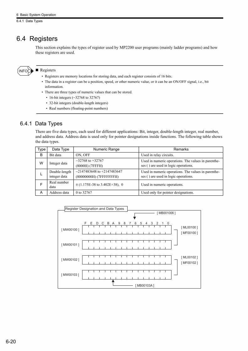
6 Basic System Operation
6.4.1 Data Types
6-20
6.4 RegistersThis section explains the types of register used by MP2200 user programs (mainly ladder programs) and how these registers are used.
Registers• Registers are memory locations for storing data, and each register consists of 16 bits. • The data in a register can be a position, speed, or other numeric value, or it can be an ON/OFF signal, i.e., bit
information. • There are three types of numeric values that can be stored.
• 16-bit integers (−32768 to 32767)• 32-bit integers (double-length integers)• Real numbers (floating-point numbers)
6.4.1 Data TypesThere are five data types, each used for different applications: Bit, integer, double-length integer, real number, and address data. Address data is used only for pointer designations inside functions. The following table shows the data types.
INFO
Type Data Type Numeric Range RemarksB Bit data ON, OFF Used in relay circuits.
W Integer data−32768 to +32767(8000H) (7FFFH)
Used in numeric operations. The values in parenthe-ses ( ) are used in logic operations.
L Double-length integer data
−2147483648 to +2147483647(80000000H) (7FFFFFFFH)
Used in numeric operations. The values in parenthe-ses ( ) are used in logic operations.
F Real number data ± (1.175E-38 to 3.402E+38), 0 Used in numeric operations.
A Address data 0 to 32767 Used only for pointer designations.
[ MW00100 ]
[ MW00103 ]
[ MW00102 ]
[ MW00101 ]
[ ML00100 ][ MF00100 ]
[ ML00102 ][ MF00102 ]
[ MB00103A ]
[ MB001006 ]
F E D C B A 9 8 7 6 5 4 3 2 1 0
Register Designation and Data Types

6.4 Registers
6-21
6
• Examples of Use by Data Type1. Bits
Bits are used for relay circuit ON/OFF status.
2. WordsWords are used for numeric operations and logic operations.
3. Double-length IntegersDouble-length integers are used for numeric operations and logic operations.
[ MB001003 ]
[ MF00100 ][ ML00100 ]
[ MW00101 ]
[ MW00103 ]
[ MW00102 ]
[ MW00100 ]
nn
[ MW00100 ][ MW00101 ]
[ MW00103 ][ MW00102 ]
Pointer Designation
Register area Memory address
EXAMPLE
MB000101IB00010
IB00001
IFON
MW00100
MW00102
MW00104
H00FF
12345
INV
+
MW00101
MW00103
MW00105
V
ML00102
ML00108 18000
BIN
ML00100
ML00106
ML00112
ML00104
ML00110
ML00114
+
× ÷
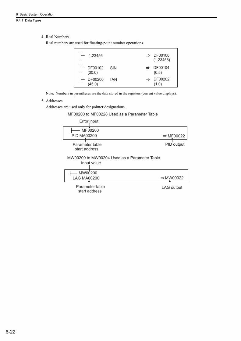
6 Basic System Operation
6.4.1 Data Types
6-22
4. Real NumbersReal numbers are used for floating-point number operations.
Note: Numbers in parentheses are the data stored in the registers (current value displays).
5. AddressesAddresses are used only for pointer designations.
(30.0) (0.5)
(45.0) (1.0)
(1.23456)
DF00102 SIN
DF00200 TAN
1.23456
DF00104
DF00202
DF00100
MW00022LAG MA00200MW00200
PID MA00200 MF00022MF00200
⇒
⇒
MW00200 to MW00204 Used as a Parameter Table
Parameter table start address
Input value
LAG output
MF00200 to MF00228 Used as a Parameter Table
PID output
Error input
Parameter table start address
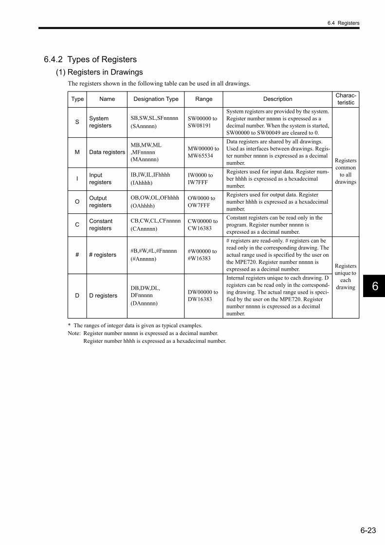
6.4 Registers
6-23
6
6.4.2 Types of Registers(1) Registers in Drawings
The registers shown in the following table can be used in all drawings.
* The ranges of integer data is given as typical examples. Note: Register number nnnnn is expressed as a decimal number.
Register number hhhh is expressed as a hexadecimal number.
Type Name Designation Type Range Description Charac-teristic
S System registers
SB,SW,SL,SFnnnnn(SAnnnnn)
SW00000 to SW08191
System registers are provided by the system. Register number nnnnn is expressed as a decimal number. When the system is started, SW00000 to SW00049 are cleared to 0.
Registers common
to all drawings
M Data registersMB,MW,ML,MFnnnnn(MAnnnnn)
MW00000 to MW65534
Data registers are shared by all drawings. Used as interfaces between drawings. Regis-ter number nnnnn is expressed as a decimal number.
I Input registers
IB,IW,IL,IFhhhh(IAhhhh)
IW0000 to IW7FFF
Registers used for input data. Register num-ber hhhh is expressed as a hexadecimal number.
O Output registers
OB,OW,OL,OFhhhh(OAhhhh)
OW0000 to OW7FFF
Registers used for output data. Register number hhhh is expressed as a hexadecimal number.
C Constant registers
CB,CW,CL,CFnnnnn(CAnnnnn)
CW00000 to CW16383
Constant registers can be read only in the program. Register number nnnnn is expressed as a decimal number.
# # registers#B,#W,#L,#Fnnnnn(#Annnnn)
#W00000 to #W16383
# registers are read-only. # registers can be read only in the corresponding drawing. The actual range used is specified by the user on the MPE720. Register number nnnnn is expressed as a decimal number. Registers
unique to each
drawingD D registers
DB,DW,DL,DFnnnnn(DAnnnnn)
DW00000 to DW16383
Internal registers unique to each drawing. D registers can be read only in the correspond-ing drawing. The actual range used is speci-fied by the user on the MPE720. Register number nnnnn is expressed as a decimal number.

6 Basic System Operation
6.4.2 Types of Registers
6-24
(2) Registers in FunctionsThe types of register shown in the following table can be used in functions.
Note: 1. Register number nnnnn is expressed as a decimal number.Register number hhhh is expressed as a hexadecimal number.
2. SA, MA, IA, OA, DA, #A, and CA can also be used in the program.
Type Name Designation Type Range Description Charac-teristic
X Function input registers XB,XW,XL,XFnnnnn XW00000 to
XW00016
Input to a function.Bit input: XB000000 to XB00000FInteger input: XW00001 to XW00016Double-length integer input: XL00001 to XL00015Register number nnnnn is expressed as a decimal number.
Registers unique to
each function
Y Function output registers YB,YW,YL,YFnnnnn YW00000 to
YW00016
Output from a function.Bit output: YB000000 to YB00000FInteger output: YW00001 to YW00016Double-length integer output: YL00001 to YL00015Register number nnnnn is expressed as a decimal number.
Z Internal function registers ZB,ZW,ZL,ZFnnnnn ZW00000 to
ZW00063
Internal registers unique to each func-tion. Can be used in the function for internal processes. Register number nnnnn is expressed as a decimal num-ber.
A External func-tion registers AB,AW,AL,AFnnnnn AW00000 to
AW32767
External registers that use the address input value as the base address.For linking with S, M, I, O, #, and DAnnnnn registers. Register number nnnnn is expressed as a decimal num-ber.
# # registers#B,#W,#L,#Fnnnnn(#Annnnn)
#W00000 to #W16383
Registers that can only be read by a function. Can be used only by the corre-sponding function. The actual range used is specified by the user on the MPE720. Register number nnnnn is expressed as a decimal number.
D D registersDB,DW,DL,DFnnnnn(DAnnnnn)
DW00000 to DW16383
Internal registers unique to each func-tion. Can be used only by the corre-sponding function. The actual range used is specified by the user on the MPE720. Register number nnnnn is expressed as a decimal number.
S System registersSB,SW,SL,SFnnnnn(SAnnnnn)
Same as drawing registers.These registers are common to drawings and functions, so care must be taken with how they are used when calling the same function from drawings with different priority levels.
M Data registersMB,MW,ML,MFnnnnn(MAnnnnn)
I Input registersIB,IW,IL,IFhhhh(IAhhhh)
O Output registersOB,OW,OL,OFhhhh(OAhhhh)
C Constant registers
CB,CW,CL,CFnnnnn(CAnnnnn)
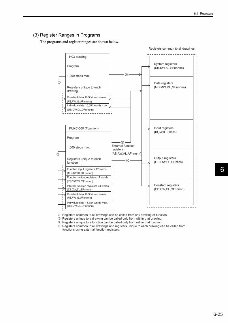
6.4 Registers
6-25
6
(3) Register Ranges in ProgramsThe programs and register ranges are shown below.
(XB,XW,XL,XFnnnnn)
(YB,YW,YL,YFnnnnn)
(ZB,ZW,ZL,ZFnnnnn)
(#B,#W,#L,#Fnnnnn)
(DB,DW,DL,DFnnnnn)
(#B,#W,#L,#Fnnnnn)
(DB,DW,DL,DFnnnnn)
(SB,SW,SL,SFnnnnn)
(MB,MW,ML,MFnnnnn)
(IB,IW,IL,IF )
(OB,OW,OL,OF )
(CB,CW,CL,CFnnnnn)
(AB,AW,AL,AFnnnnn)
FUNC-000 (Function)
Program
1,000 steps max.
Registers unique to each function
Function input registers 17 words
Function output registers 17 words
Internal function registers 64 words
Constant data 16,384 words max.
Individual data 16,384 words max.
H03 drawing
Program
1,000 steps max.
Registers unique to each drawing
Constant data 16,384 words max.
Individual data 16,384 words max.
System registers
Registers common to all drawings
Data registers
Input registers
Output registers
Constant registers
External function registers
: Registers common to all drawings can be called from any drawing or function. : Registers unique to a drawing can be called only from within that drawing. : Registers unique to a function can be called only from within that function. : Registers common to all drawings and registers unique to each drawing can be called from
functions using external function registers.
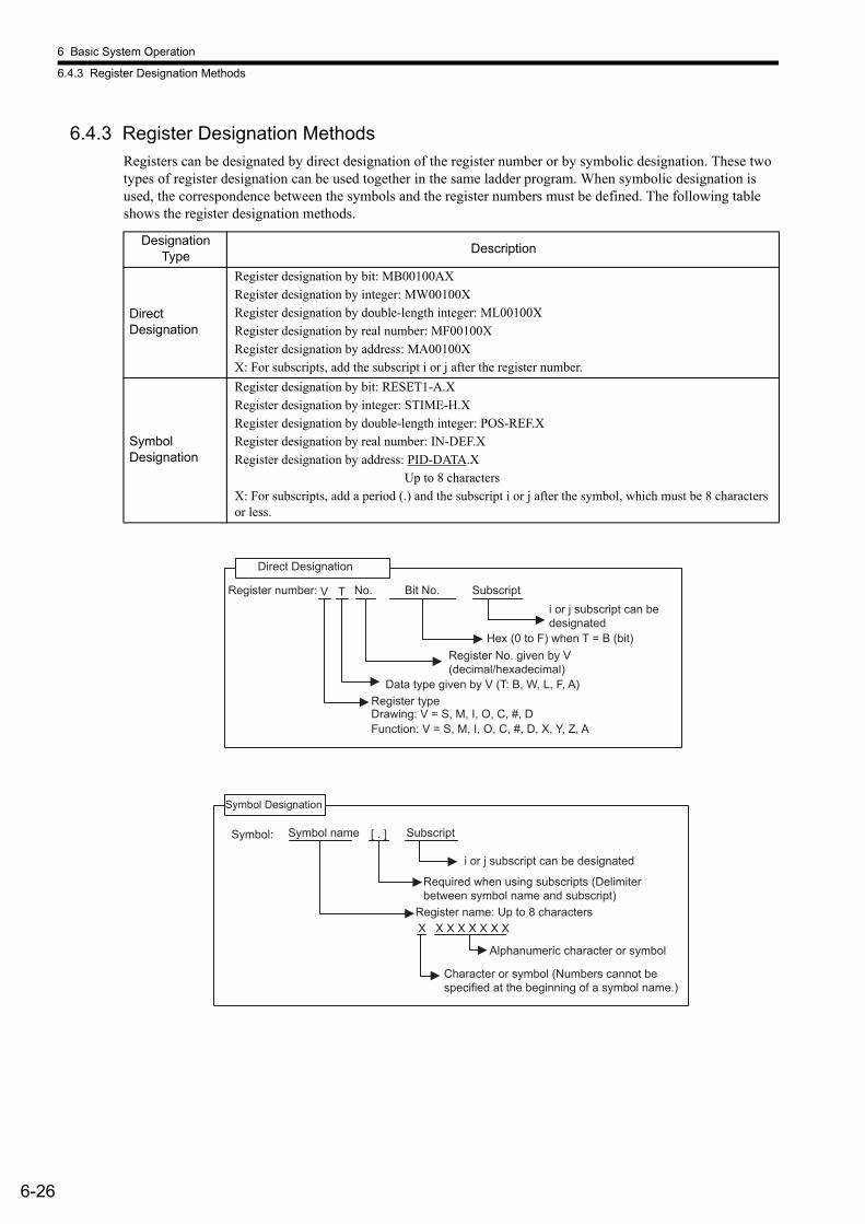
6 Basic System Operation
6.4.3 Register Designation Methods
6-26
6.4.3 Register Designation MethodsRegisters can be designated by direct designation of the register number or by symbolic designation. These two types of register designation can be used together in the same ladder program. When symbolic designation is used, the correspondence between the symbols and the register numbers must be defined. The following table shows the register designation methods.
Designation Type Description
Direct Designation
Register designation by bit: MB00100AXRegister designation by integer: MW00100XRegister designation by double-length integer: ML00100X Register designation by real number: MF00100XRegister designation by address: MA00100XX: For subscripts, add the subscript i or j after the register number.
Symbol Designation
Register designation by bit: RESET1-A.XRegister designation by integer: STIME-H.XRegister designation by double-length integer: POS-REF.XRegister designation by real number: IN-DEF.XRegister designation by address: PID-DATA.X Up to 8 charactersX: For subscripts, add a period (.) and the subscript i or j after the symbol, which must be 8 characters or less.
V T
Direct Designation
Register number: No. Bit No. Subscript i or j subscript can be designated
Hex (0 to F) when T = B (bit)Register No. given by V (decimal/hexadecimal)
Register type Drawing: V = S, M, I, O, C, #, DFunction: V = S, M, I, O, C, #, D, X, Y, Z, A
Data type given by V (T: B, W, L, F, A)
[ . ]
X X X X X X X X
Symbol Designation
Symbol: Symbol name Subscript
i or j subscript can be designated
Required when using subscripts (Delimiter between symbol name and subscript)
Alphanumeric character or symbol
Character or symbol (Numbers cannot be specified at the beginning of a symbol name.)
Register name: Up to 8 characters

6.4 Registers
6-27
6
6.4.4 Subscripts i and jTwo subscripts, i and j, are used for modifying relay numbers and register numbers. i and j have exactly the same function. An example of each register data type is explained below.
(1) Bit Data with a SubscriptWhen a subscript is attached to bit data, the value of i or j is added to the relay number. For example, if i = 2, MB000000i will be the same as MB000002. If j = 27, MB000000j will be the same as MB00001B.
(2) Integer Data with a SubscriptWhen a subscript is attached to integer data, the value of i or j is added to the register number. For example, if i = 3, MW00010i will be the same as MW00013. If j = 30, MW00001j will be the same as MW00031.
(3) Double-length Integer Data with a SubscriptWhen a subscript is attached to double-length integer data, the value of i or j is added to the register number. For example, if i = 1, ML00000i will be the same as ML00001. ML00000j when j = 0, and ML00000j when j = 1 will be as follows:
MB0000002
MB000000i
2Equivalent
00030
MW00001j
MW00031JEquivalent
MW00001 MW00000
MW00002 MW00001
ML00000j when j = 0: ML00000
ML00000j when j = 1: ML00001
Upper-place word Lower-place word

6 Basic System Operation
6.4.4 Subscripts i and j
6-28
(4) Real Number Data with a SubscriptWhen a subscript is attached to real number data, the value of i or j is added to the register number. For example, if i = 1, MF00000i will be the same as MF00001. MF00000j when j = 0, and MF00000j when j = 1 will be as fol-lows:
Programming Example Using a SubscriptThe following program sets the sum of 100 registers from MW00100 to MW00199 in MW00200 using subscript j.
Programming Example Using a Subscript
MW00001 MW00000
MW00002 MW00001
MF00000j when j = 0: MF00000
MF00000j when j = 1: MF00001
Upper-place word Lower-place word
EXAMPLE
00000
FOR j = 00000 to 00099 by 00001
MW00200 + MW00100j
FEND
MW00200
MW00200
⇒
⇒
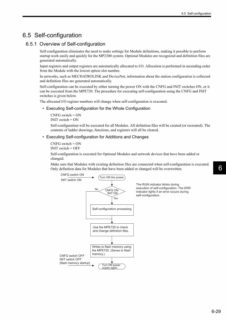
6.5 Self-configuration
6-29
6
6.5 Self-configuration6.5.1 Overview of Self-configuration
Self-configuration eliminates the need to make settings for Module definitions, making it possible to perform startup work easily and quickly for the MP2200 system. Optional Modules are recognized and definition files are generated automatically.Input registers and output registers are automatically allocated to I/O. Allocation is performed in ascending order from the Module with the lowest option slot number.In networks, such as MECHATROLINK and DeviceNet, information about the station configuration is collected and definition files are generated automatically.Self-configuration can be executed by either turning the power ON with the CNFG and INIT switches ON, or it can be executed from the MPE720. The procedure for executing self-configuration using the CNFG and INIT switches is given below.The allocated I/O register numbers will change when self-configuration is executed.
• Executing Self-configuration for the Whole ConfigurationCNFG switch = ONINIT switch = ONSelf-configuration will be executed for all Modules. All definition files will be created (or recreated). The contents of ladder drawings, functions, and registers will all be cleared.
• Executing Self-configuration for Additions and ChangesCNFG switch = ONINIT switch = OFFSelf-configuration is executed for Optional Modules and network devices that have been added or changed.Make sure that Modules with existing definition files are connected when self-configuration is executed. Only definition data for Modules that have been added or changed will be overwritten.
CNFG ON
Yes
NoINIT ON
The RUN indicator blinks during execution of self-configuration. The ERR indicator lights if an error occurs during self-configuration.
CNFG switch ON Turn ON the power.
Self-configuration processing
Use the MPE720 to check and change definition files.
Turn ON power supply again.
CNFG switch OFF INIT switch OFF (flash memory startup)
INIT switch ON
Writes to flash memory using the MPE720. (Saves to flash memory.)
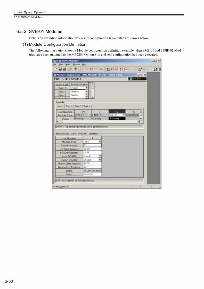
6 Basic System Operation
6.5.2 SVB-01 Modules
6-30
6.5.2 SVB-01 ModulesDetails on definition information when self-configuration is executed are shown below.
(1) Module Configuration DefinitionThe following illustration shows a Module configuration definition example when SVB-01 and 218IF-01 Mod-ules have been mounted to the MP2200 Option Slot and self-configuration has been executed.
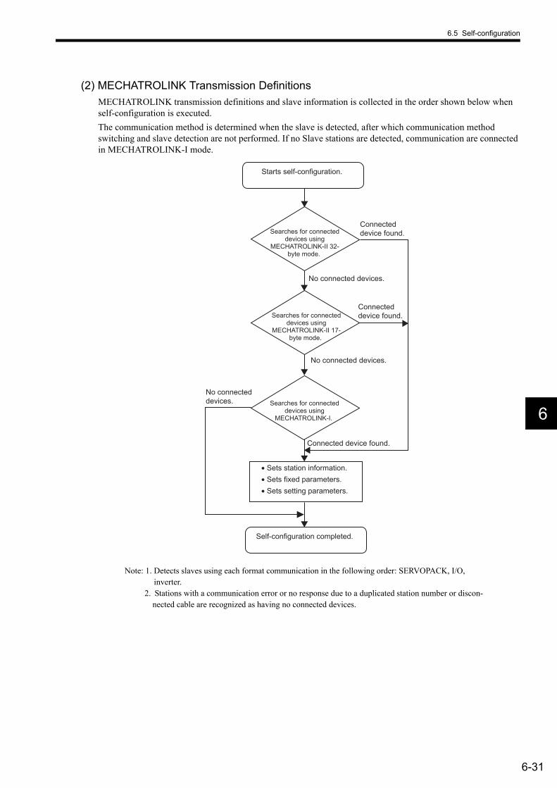
6.5 Self-configuration
6-31
6
(2) MECHATROLINK Transmission DefinitionsMECHATROLINK transmission definitions and slave information is collected in the order shown below when self-configuration is executed.The communication method is determined when the slave is detected, after which communication method switching and slave detection are not performed. If no Slave stations are detected, communication are connected in MECHATROLINK-I mode.
Note: 1. Detects slaves using each format communication in the following order: SERVOPACK, I/O, inverter.
2. Stations with a communication error or no response due to a duplicated station number or discon-nected cable are recognized as having no connected devices.
Starts self-configuration.
Self-configuration completed.
• Sets station information. • Sets fixed parameters. • Sets setting parameters.
Connected device found.
Connected device found.
Connected device found.
No connected devices.
No connected devices.
No connected devices.
Searches for connected devices using
MECHATROLINK-II 32-byte mode.
Searches for connected devices using
MECHATROLINK-I.
Searches for connected devices using
MECHATROLINK-II 17-byte mode.

6 Basic System Operation
6.5.2 SVB-01 Modules
6-32
(a) Common Setting Items
Note: 1. The hardware switch has priority for the master/slave setting. Definitions for the MPE720 must match the hardware switch settings.
2. Slaves function as intelligent I/O.
(b) Settings and Display Items by Communication Method• MECHATROLINK-I
• Master
• Slaves
Item Setting Contents Default Value
Communication method
Sets the communication method. Selections: • MECHATROLINK-I• MECHATROLINK-II (17-byte mode) • MECHATROLINK-II (32-byte mode)
MECHATROLINK-II (32-byte mode)
Master/Slave
Sets the Module to a master or a slave. Selections: • Master• Slave
Master
Own station num-ber (local station number)
The local station address for the master is 0 (fixed). The local station address for a slave is 1 to the number of slaves. The number of slaves can be changed using commu-nication.
0
Item Details Default ValueBaud rate Fixed value; display only. 4 MbpsCommunication cycle Fixed value; display only. 2 ms
Message reliability level 0, 1, or 2 0
Number of slave stations Fixed value; display only. 14
Item Details Default Value
Baud rate Fixed value; display only. 4 Mbps 4 Mbps
Communication cycle
Fixed value; display only. 2 ms 2 ms
Message reliability level Setting not required. 0
Number of slave stations
Fixed value; display only. 15 15

6.5 Self-configuration
6-33
6
• MECHATROLINK-II (17-byte Mode)
• Master
* If the communication cycle is 0.5 ms, the maximum number of retry stations is 5.
• Slaves
Item Details Default ValueBaud rate Fixed value; display only. 10 MbpsNo. send bytes Fixed value; display only. 16 bytesCommunication cycle 0.5 ms or 1 ms 1 ms
SigmaWinSet whether or not there is a SigmaWin connection. Selections: Yes/No
None
No. of retry stations (messages)
Sets the number of retry stations. Setting range: 0 to 7
1
Number of slave stations
Automatically determined by the SigmaWin setting and the number of retry stations setting. The results is displayed and cannot be changed. Setting range: 0 to 15 The number of slave stations is calculated using the following equation. SigmaWin Yes: 1, No: 0• Communication cycle: 0.5 ms
Number of slave stations = 6 − (No. of retry stations∗ + SigmaWin)• Communication cycle: 1 ms
Number of slave stations = 15 − (No. of retry stations + SigmaWin)
14
Item Details Default Value
Baud rate Fixed value; display only. 10 Mbps 10 Mbps
No. send bytes Fixed value; display only. 16 bytes 16 bytes
Communication cycle Setting not required. 1 ms
SigmaWin Setting not required. None
No. of retry stations(messages)
Setting not required. 1
Number of slave stations
Fixed value; display only. 30 30
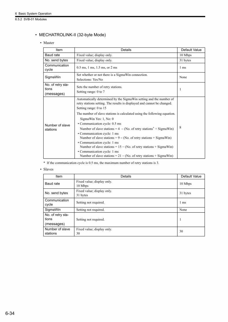
6 Basic System Operation
6.5.2 SVB-01 Modules
6-34
• MECHATROLINK-II (32-byte Mode)
• Master
* If the communication cycle is 0.5 ms, the maximum number of retry stations is 3.
• Slaves
Item Details Default ValueBaud rate Fixed value; display only. 10 MbpsNo. send bytes Fixed value; display only. 31 bytesCommunication cycle 0.5 ms, 1 ms, 1.5 ms, or 2 ms 1 ms
SigmaWinSet whether or not there is a SigmaWin connection. Selections: Yes/No
None
No. of retry sta-tions (messages)
Sets the number of retry stations. Setting range: 0 to 7
1
Number of slave stations
Automatically determined by the SigmaWin setting and the number of retry stations setting. The results is displayed and cannot be changed. Setting range: 0 to 15 The number of slave stations is calculated using the following equation. SigmaWin Yes: 1, No: 0• Communication cycle: 0.5 ms
Number of slave stations = 4 − (No. of retry stations∗ + SigmaWin)• Communication cycle: 1 ms
Number of slave stations = 9 − (No. of retry stations + SigmaWin)• Communication cycle: 1 ms
Number of slave stations = 15 − (No. of retry stations + SigmaWin)• Communication cycle: 1 ms
Number of slave stations = 21 − (No. of retry stations + SigmaWin)
8
Item Details Default Value
Baud rate Fixed value; display only. 10 Mbps 10 Mbps
No. send bytes Fixed value; display only. 31 bytes 31 bytes
Communication cycle Setting not required. 1 ms
SigmaWin Setting not required. None No. of retry sta-tions(messages)
Setting not required. 1
Number of slave stations
Fixed value; display only. 30 30
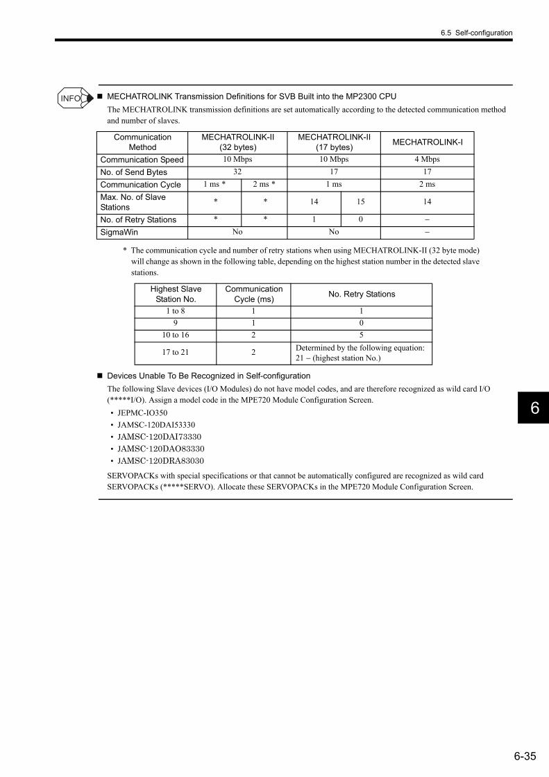
6.5 Self-configuration
6-35
6
MECHATROLINK Transmission Definitions for SVB Built into the MP2300 CPUThe MECHATROLINK transmission definitions are set automatically according to the detected communication method and number of slaves.
* The communication cycle and number of retry stations when using MECHATROLINK-II (32 byte mode) will change as shown in the following table, depending on the highest station number in the detected slave stations.
Devices Unable To Be Recognized in Self-configurationThe following Slave devices (I/O Modules) do not have model codes, and are therefore recognized as wild card I/O (*****I/O). Assign a model code in the MPE720 Module Configuration Screen. • JEPMC-IO350• JAMSC-120DAI53330• JAMSC-120DAI73330• JAMSC-120DAO83330• JAMSC-120DRA83030
SERVOPACKs with special specifications or that cannot be automatically configured are recognized as wild card SERVOPACKs (*****SERVO). Allocate these SERVOPACKs in the MPE720 Module Configuration Screen.
Communication Method
MECHATROLINK-II(32 bytes)
MECHATROLINK-II (17 bytes) MECHATROLINK-I
Communication Speed 10 Mbps 10 Mbps 4 MbpsNo. of Send Bytes 32 17 17Communication Cycle 1 ms * 2 ms * 1 ms 2 msMax. No. of Slave Stations
* * 14 15 14
No. of Retry Stations * * 1 0 −SigmaWin No No −
Highest Slave Station No.
Communication Cycle (ms) No. Retry Stations
1 to 8 1 19 1 0
10 to 16 2 5
17 to 21 2 Determined by the following equation: 21 − (highest station No.)
INFO
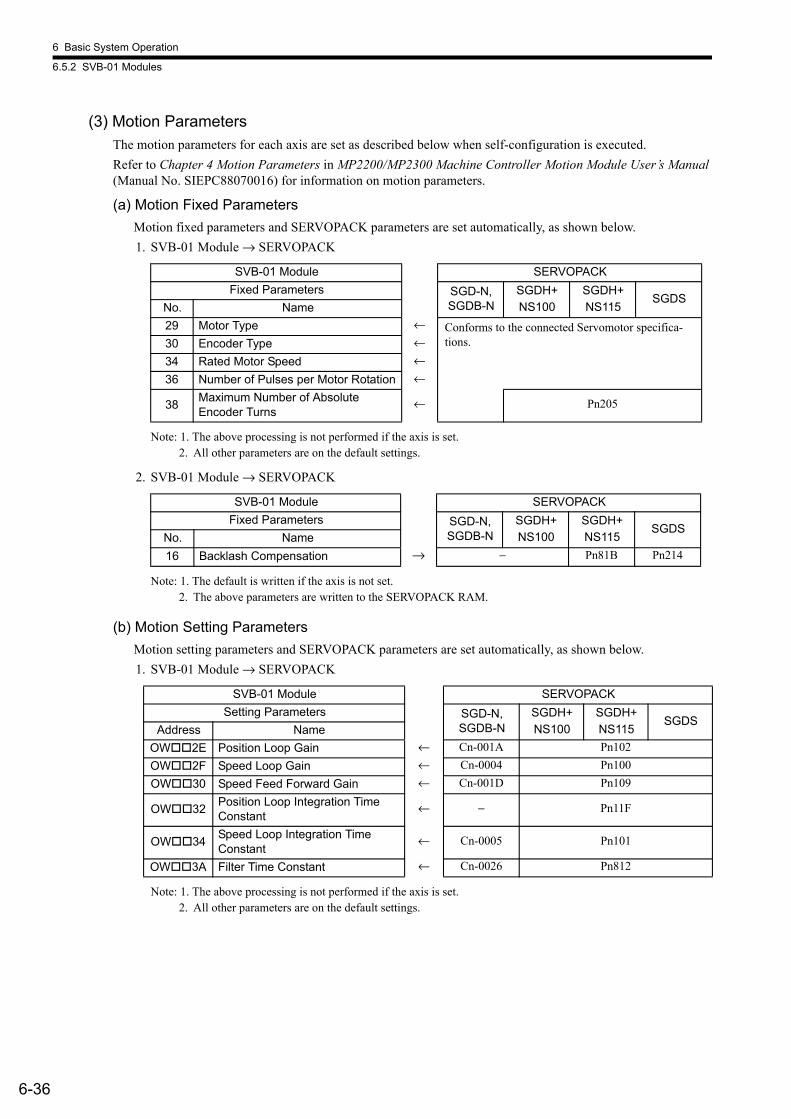
6 Basic System Operation
6.5.2 SVB-01 Modules
6-36
(3) Motion ParametersThe motion parameters for each axis are set as described below when self-configuration is executed. Refer to Chapter 4 Motion Parameters in MP2200/MP2300 Machine Controller Motion Module User’s Manual (Manual No. SIEPC88070016) for information on motion parameters.
(a) Motion Fixed ParametersMotion fixed parameters and SERVOPACK parameters are set automatically, as shown below.1. SVB-01 Module → SERVOPACK
Note: 1. The above processing is not performed if the axis is set.2. All other parameters are on the default settings.
2. SVB-01 Module → SERVOPACK
Note: 1. The default is written if the axis is not set.2. The above parameters are written to the SERVOPACK RAM.
(b) Motion Setting ParametersMotion setting parameters and SERVOPACK parameters are set automatically, as shown below.1. SVB-01 Module → SERVOPACK
Note: 1. The above processing is not performed if the axis is set.2. All other parameters are on the default settings.
SVB-01 Module SERVOPACKFixed Parameters SGD-N,
SGDB-NSGDH+NS100
SGDH+NS115
SGDSNo. Name29 Motor Type ← Conforms to the connected Servomotor specifica-
tions.30 Encoder Type ←34 Rated Motor Speed ←36 Number of Pulses per Motor Rotation ←
38 Maximum Number of Absolute Encoder Turns
← Pn205
SVB-01 Module SERVOPACKFixed Parameters SGD-N,
SGDB-NSGDH+NS100
SGDH+NS115
SGDSNo. Name16 Backlash Compensation → − Pn81B Pn214
SVB-01 Module SERVOPACKSetting Parameters SGD-N,
SGDB-NSGDH+NS100
SGDH+NS115
SGDSAddress Name
OW 2E Position Loop Gain ← Cn-001A Pn102OW 2F Speed Loop Gain ← Cn-0004 Pn100OW 30 Speed Feed Forward Gain ← Cn-001D Pn109
OW 32 Position Loop Integration Time Constant
← − Pn11F
OW 34 Speed Loop Integration Time Constant
← Cn-0005 Pn101
OW 3A Filter Time Constant ← Cn-0026 Pn812
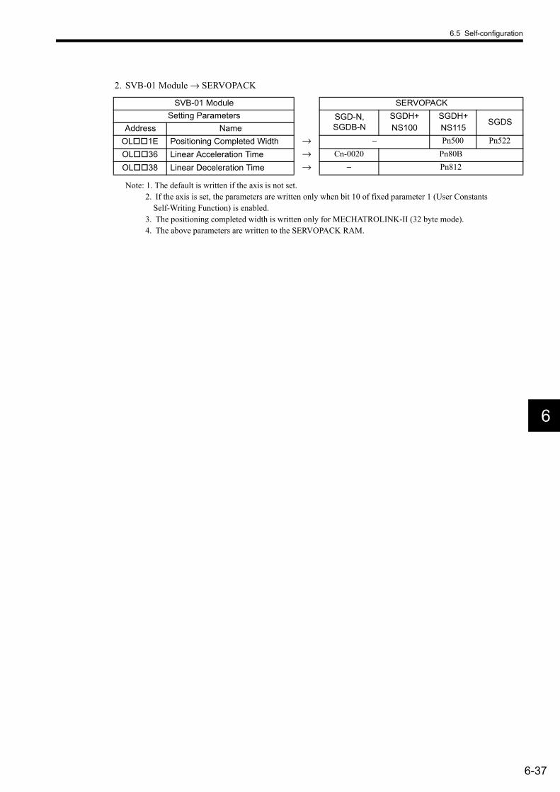
6.5 Self-configuration
6-37
6
2. SVB-01 Module → SERVOPACK
Note: 1. The default is written if the axis is not set.2. If the axis is set, the parameters are written only when bit 10 of fixed parameter 1 (User Constants
Self-Writing Function) is enabled.3. The positioning completed width is written only for MECHATROLINK-II (32 byte mode).4. The above parameters are written to the SERVOPACK RAM.
SVB-01 Module SERVOPACKSetting Parameters SGD-N,
SGDB-NSGDH+NS100
SGDH+NS115
SGDSAddress Name
OL 1E Positioning Completed Width → − Pn500 Pn522
OL 36 Linear Acceleration Time → Cn-0020 Pn80B
OL 38 Linear Deceleration Time → − Pn812
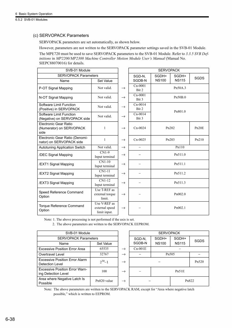
6 Basic System Operation
6.5.2 SVB-01 Modules
6-38
(c) SERVOPACK ParametersSERVOPACK parameters are set automatically, as shown below.However, parameters are not written to the SERVOPACK parameter settings saved in the SVB-01 Module.The MPE720 must be used to save SERVOPACK parameters to the SVB-01 Module. Refer to 3.3.5 SVB Def-initions in MP2200/MP2300 Machine Controller Motion Module User’s Manual (Manual No. SIEPC88070016) for details.
Note: 1. The above processing is not performed if the axis is set.2. The above parameters are written to the SERVOPACK EEPROM.
Note: The above parameters are written to the SERVOPACK RAM, except for “Area where negative latch possible,” which is written to EEPROM.
SVB-01 Module SERVOPACKSERVOPACK Parameters SGD-N,
SGDB-NSGDH+NS100
SGDH+NS115 SGDS
Name Set Value
P-OT Signal Mapping Not valid. → Cn-0001Bit 2 Pn50A.3
N-OT Signal Mapping Not valid. → Cn-0001Bit 3 Pn50B.0
Software Limit Function (Positive) in SERVOPACK
Not valid. → Cn-0014Bit 2
Pn801.0Software Limit Function (Negative) on SERVOPACK side
Not valid. → Cn-0014Bit 3
Electronic Gear Ratio (Numerator) on SERVOPACK side
1 → Cn-0024 Pn202 Pn20E
Electronic Gear Ratio (Denomi-nator) on SERVOPACK side
1 → Cn-0025 Pn203 Pn210
Autotuning Application Switch Not valid. → − Pn110
/DEC Signal MappingCN1-9
Input terminal → − Pn511.0
/EXT1 Signal MappingCN1-10
Input terminal → − Pn511.1
/EXT2 Signal MappingCN1-11
Input terminal → − Pn511.2
/EXT3 Signal MappingCN1-12
Input terminal → − Pn511.3
Speed Reference Command Option
Use T-REF as external torque
limit.→ − Pn002.0
Torque Reference Command Option
Use V-REF as external speed
limit input.→ − Pn002.1
SVB-01 Module SERVOPACKSERVOPACK Parameters SGD-N,
SGDB-NSGDH+NS100
SGDH+NS115
SGDSName Set Value
Excessive Position Error Area 65535 → Cn-001E −
Overtravel Level 32767 → − Pn505 −Excessive Position Error Alarm Detection Level 230−1 → − Pn520
Excessive Position Error Warn-ing Detection Level
100 → − Pn51E
Area where Negative Latch Is Possible
Pn820 value → − Pn822
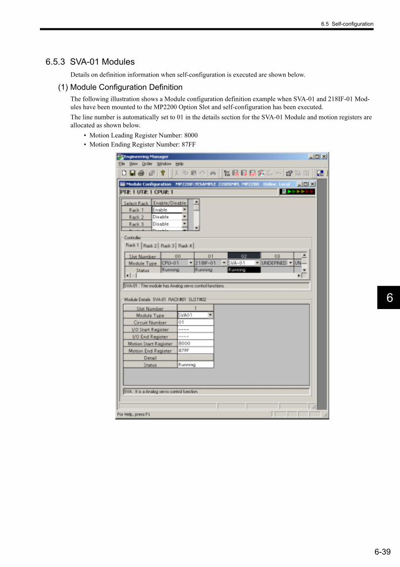
6.5 Self-configuration
6-39
6
6.5.3 SVA-01 ModulesDetails on definition information when self-configuration is executed are shown below.
(1) Module Configuration DefinitionThe following illustration shows a Module configuration definition example when SVA-01 and 218IF-01 Mod-ules have been mounted to the MP2200 Option Slot and self-configuration has been executed.The line number is automatically set to 01 in the details section for the SVA-01 Module and motion registers are allocated as shown below.
• Motion Leading Register Number: 8000• Motion Ending Register Number: 87FF

6 Basic System Operation
6.5.4 LIO-01 Modules
6-40
6.5.4 LIO-01 ModulesDetails on definition information when self-configuration is executed are shown below.
(1) I/O AllocationsModules mounted in option slots are detected and input registers and output registers are allocated automatically. Allocation is performed in ascending order from the Module with the lowest option slot number.With LIO-01 Modules, 48 words are allocated for both input registers and output registers.
Note: The above allocations are simply an example. The leading register number will change for manual allocations.
(2) Counter Fixed ParametersWhen self-configuration is executed, all of the counter fixed parameters will take their default settings. For details on fixed parameters, refer to 4.8.4 Counter Parameters.
Item Allocations
Digital inputs (16 points)
Out of the 48 words allocated to one Module, the first word is automatically allocated to input registers.Example:If LIO-01 Modules are mounted in slots 1 and 2, digital inputs will be allocated in the following way:LIO-01 Module mounted in slot 1: IW0410, LIO-01 Module mounted in slot 2: IW0440
Digital output (16 points)
Out of the 48 words allocated to one Module, the second word is automatically allocated to output reg-isters.Example:If LIO-01 Modules are mounted in slots 1 and 2, digital outputs will be allocated in the following way:LIO-01 Module mounted in slot 1: OW0411, LIO-01 Module mounted in slot 2: OW0441
Counters
Out of the 48 words allocated to one Module, the last 32 words are automatically allocated to the input and output registers.Example:If LIO-01 Modules are mounted in slots 1 and 2, counters will be allocated in the following way:LIO-01 Module mounted in slot 1: IW0420/OW0420, LIO-01 Module mounted in slot 2: IW0450/OW0450

6.5 Self-configuration
6-41
6
6.5.5 LIO-02 ModulesDetails on definition information when self-configuration is executed are shown below.
(1) I/O AllocationsModules mounted in option slots are detected, and input registers and output registers are allocated automatically.Allocation is performed in ascending order from the Module with the lowest option slot number.With LIO-02 Modules, 48 words are allocated to both input registers and output registers.
Note: The above allocations are simply an example. The leading register number will change for manual alloca-tions.
(2) Counter Fixed ParametersWhen self-configuration is executed, all of the counter fixed parameters will take their default settings. For details on fixed parameters, refer to 4.8.4 Counter Parameters.
Item Allocations
Digital inputs (16 points)
Out of the 48 words allocated to one Module, the first word is automatically allocated to input regis-ters.Example:If LIO-02 Modules are mounted in slots 1 and 2, digital inputs will be allocated in the following way:LIO-02 Module mounted in slot 1: IW0410, LIO-02 Module mounted in slot 2: IW0440
Digital output (16 points)
Out of the 48 words allocated to one Module, the second word is automatically allocated to output registers.Example:If LIO-02 Modules are mounted in slots 1 and 2, digital outputs will be allocated in the following way:LIO-02 Module mounted in slot 1: OW0411, LIO-02 Module mounted in slot 2: OW0441
Counters
Out of the 48 words allocated to one Module, the last 32 words are automatically allocated to the input and output registers.Example:If LIO-02 Modules are mounted in slots 1 and 2, counters will be allocated in the following way:LIO-02 Module mounted in slot 1: IW0420/OW0420, LIO-02 Module mounted in slot 2: IW0450/OW0450

6 Basic System Operation
6.5.6 LIO-04 Modules
6-42
6.5.6 LIO-04 ModulesDetails on definition information when self-configuration is executed are shown below.
(1) I/O AllocationsModules mounted in option slots are detected and input registers and output registers are allocated automatically. Allocation is performed in ascending order from the Module with the lowest option slot number.
With LIO-04 Modules, 2 words are allocated to both input registers and output registers.
Note: The above allocations are simply an example. The leading register number will change for manual alloca-tions.
Item Allocations
Digital inputs (16 points)
Out of the 2 words allocated to one Module, the first word is automatically allocated to input registers.Example: If LIO-04 Modules are mounted in slots 1 and 2, digital inputs will be allocated in the following way:
LIO-04 Module mounted in slot 1: IW0410 and IW0411LIO-04 Module mounted in slot 2: IW0420 and IW0421
Digital output (16 points)
Two words per Module are automatically allocated to output registers.Example: If LIO-04 Modules are mounted in slots 1 and 2, digital outputs will be allocated in the following way:
LIO-04 Module mounted in slot 1: OW0410 and OW0411LIO-04 Module mounted in slot 2: OW0420 and OW0421

6.5 Self-configuration
6-43
6
6.5.7 218IF-01 Modules(1) Ethernet Interface
When self-configuration is executed, the following parameter settings will be made for the Ethernet interface of 218IF-01 Modules.
An engineering communication connection with the MPE720 is possible using self-configuration. To perform MEMOBUS message communication, the MSG-SND (MSG-RCV) function is required.
(2) RS-232C InterfaceWhen self-configuration is executed, the following parameter settings will be made for the RS-232C interface of 218IF-01 Modules.
An engineering communication connection with the MPE720 is possible using self-configuration. Also, depending on the settings of connected devices, MEMOBUS message communication may be possible using the automatic reception func-tion.
Item AllocationsLocal IP Address 192.168.1.1Subnet Mask 255.255.255.0Gateway IP Address 0.0.0.0System Port (Engineering Port) 10000 (UDP )TCP Zero Window Timer Value 3 sTCP Resend Timer Value 500 msTCP End Timer Value 60 sIP Build Timer 30 sMax. Packet Length 1500 bytes
INFO
Item AllocationsCommunication Protocol MEMOBUSMaster/Slave SlaveDevice Address 1Serial Interface RS-232CCommunication Mode RTUData Length 8 BitParity EVENStop Bits 1 StopBaud Rate 19.2 kbpsTransmission Delay DisableAutomatic Reception Enable
Interface Register Settings at the Slave
Leading Register No. of WordsReading input relays IW0000 5120Reading input registers IW0000 5120Reading/writing coils MW00000 32768Reading/writing holding registers MW00000 32768
Writing range for coil holding registers
MW00000LO MW00000HI MW32767
INFO

6 Basic System Operation
6.5.8 217IF-01 Modules
6-44
6.5.8 217IF-01 Modules(1) RS-422/485 Interface
When self-configuration is executed, the following parameter settings will be made for the RS-422/485 interface of 217IF-01 Modules.
Also, depending on the settings of connected devices, MEMOBUS message communication may be possible using the automatic reception function when self-configuration is executed.
Item AllocationsCommunication Protocol MEMOBUSMaster/Slave SlaveDevice Address 1Serial Interface RS-485Communication Mode RTUData Length 8 BitParity EVENStop Bits 1 StopBaud Rate 19.2 kbpsTransmission Delay DisableAutomatic Reception Enable
Interface Register Settings at the Slave
Leading Register No. of WordsReading input relays IW0000 5120Reading input registers IW0000 5120Reading/writing coils MW00000 32768Reading/writing holding registers MW00000 32768
Writing range for coil holding registers
MW00000LO MW00000HI MW32767
INFO

6.5 Self-configuration
6-45
6
(2) RS-232C InterfaceWhen self-configuration is executed, the following parameter settings will be made for the RS-232C interface of 217IF-01 Modules.
An engineering communication connection with the MPE720 is possible using self-configuration. Also, depending on the settings of connected devices, MEMOBUS message communication may be possible using the automatic reception func-tion.
Item AllocationsCommunication Protocol MEMOBUSMaster/Slave SlaveDevice Address 1Serial Interface RS-232CCommunication Mode RTUData Length 8 BitParity EVENStop Bits 1 StopBaud Rate 19.2 kbpsTransmission Delay DisableAutomatic Reception Enable
Interface Register Settings at the Slave
Leading Register No. of WordsReading input relays IW0000 5120Reading input registers IW0000 5120Reading/writing coils MW00000 32768Reading/writing holding registers MW00000 32768
Writing range for coil holding registers
MW00000LO MW00000HI MW32767
INFO
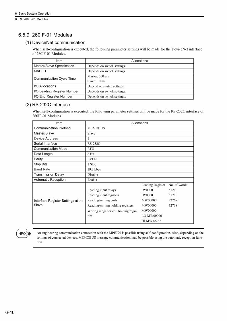
6 Basic System Operation
6.5.9 260IF-01 Modules
6-46
6.5.9 260IF-01 Modules(1) DeviceNet communication
When self-configuration is executed, the following parameter settings will be made for the DeviceNet interface of 260IF-01 Modules.
(2) RS-232C InterfaceWhen self-configuration is executed, the following parameter settings will be made for the RS-232C interface of 260IF-01 Modules.
An engineering communication connection with the MPE720 is possible using self-configuration. Also, depending on the settings of connected devices, MEMOBUS message communication may be possible using the automatic reception func-tion.
Item AllocationsMaster/Slave Specification Depends on switch settings.MAC ID Depends on switch settings.
Communication Cycle TimeMaster: 300 msSlave: 0 ms
I/O Allocations Depend on switch settings.I/O Leading Register Number Depends on switch settings.I/O End Register Number Depends on switch settings.
Item AllocationsCommunication Protocol MEMOBUSMaster/Slave SlaveDevice Address 1Serial Interface RS-232CCommunication Mode RTUData Length 8 BitParity EVENStop Bits 1 StopBaud Rate 19.2 kbpsTransmission Delay DisableAutomatic Reception Enable
Interface Register Settings at the Slave
Leading Register No. of WordsReading input relays IW0000 5120Reading input registers IW0000 5120Reading/writing coils MW00000 32768Reading/writing holding registers MW00000 32768
Writing range for coil holding regis-ters
MW00000LO MW00000HI MW32767
INFO

6.5 Self-configuration
6-47
6
6.5.10 261IF-01 Modules(1) PROFIBUS Interface
When self-configuration is executed, the following parameter settings will be made for the PROFIBUS interface of 261IF-01 Modules.
(2) RS-232C InterfaceWhen self-configuration is executed, the following parameter settings will be made for the RS-232C interface of 261IF-01 Modules.
An engineering communication connection with the MPE720 is possible using self-configuration. Also, depending on the settings of connected devices, MEMOBUS message communication may be possible using the automatic reception func-tion.
Item AllocationsSYNC-SCAN LowOwn Station Number (Local Sta-tion Number) Depends on switch settings.
I/O Allocations Depend on switch settings.Communication Speed Automatically detected from the masters transmission data.I/O Leading Register Number Depends on switch settings.I/O End Register Number Depends on switch settings.
Item AllocationsCommunication Protocols MEMOBUSMaster/Slave SlaveDevice Address 1Serial Interface RS-232CCommunication Mode RTUData Length 8 BitParity EVENStop Bits 1 StopBaud Rate 19.2 kbpsTransmission Delay DisableAutomatic Reception Enable
Interface Register Settings at the Slave
Leading Register No. of WordsReading input relays IW0000 5120Reading input registers IW0000 5120Reading/writing coils MW00000 32768Reading/writing holding registers MW00000 32768
Writing range for coil holding registers
MW00000LO MW00000HI MW32767
INFO
6 Basic System Operation
6.6.1 Saving User-defined Files or Data
6-48
6.6 Setting and Changing User-defined Files or DataThis section explains precautions when changing the scan times, Module configuration definition, or other set-tings.
• Scan times: The cycles used to refresh all I/O, execute the ladder programs, etc.• Module configuration definition: Settings for the Modules comprising the MP2200 and functions
6.6.1 Saving User-defined Files or DataUser-defined files and data must be saved in flash memory. Whenever setting or changing user-defined files, use the MPE720 to save them to flash memory. If the files or data is not saved, the settings and changes will be lost the next time the power supply to the MP2200 is turned OFF.
6.6.2 Setting and Changing the Scan TimesObserve the following precautions when setting and changing the scan times.
• When setting the high-speed and low-speed scans, set them so that they are larger than the maximum exe-cution times. Use the following equation as a guideline: (Scan setting − Max. execution time) ≥ (0.2 × Scan setting) ... (20% or more of the setting)
• If a scan setting is close to the maximum execution time, refreshing the displays on the MPE720 will be extremely slow and communication timeouts will occur. If the maximum execution time exceeds the scan setting, a watchdog time out error will occur and the MP2200 system will stop.
• Set the high-speed and low-speed scans to integral multiples of the MECHATROLINK communication cycle of the SVB-01 Module. If you change the MECHATROLINK communication cycle, be sure to check the scan time settings.
• High-speed and Low-speed Scan Setting Example for the SVB-01 Module• Set the high-speed and low-speed scans to integral multiples of the MECHATROLINK communication
cycle. • If you change the MECHATROLINK communication cycle, be sure to check the scan time settings.• Setting Example (The calculations are the same for low-speed scans.)
• For communication cycle = 1 ms (possible only when MECHATROLINK-II is used)and max. execution time is ≤ 0.8 msHigh-speed scan setting ≥ (1.25 × 0.8) = 1 msHigh-speed scan setting = 1 ms, 2 ms, 3 ms, etc. (an integral multiple of 1 ms or higher)
• For communication cycle = 1 ms (possible only when MECHATROLINK-II is used)and max. execution time is ≤ 1.4 msHigh-speed scan setting ≥ (1.25 × 1.4) = 1.75 msHigh-speed scan setting = 2 ms, 3 ms, etc. (an integral multiple of 2 ms or higher)
• For communication cycle = 2 ms (when MECHATROLINK-I or MECHATROLINK-II is used)and max. execution time is ≤ 0.8 msHigh-speed scan setting ≥ (1.25 × 0.8) = 1 msHigh-speed scan setting = 1 ms, 2 ms, 4 ms, etc. (1 ms and 2 ms or an integral multiple of 2 ms or higher)
• For communication cycle = 2 ms (when MECHATROLINK-I or MECHATROLINK-II is used)and max. execution time is ≤ 1.4 msHigh-speed scan setting ≥ (1.25 × 1.4) = 1.75 msHigh-speed scan setting = 2 ms, 4 ms, etc. (an integral multiple of 2 ms)
• Never change the scan time settings when the Servo is ON, particularly when an axis is moving (i.e., when the motor is running). Doing so may cause errors in motor rotation operations, such as high-speed rota-tion.
• Always save any data that has been set or changed to flash memory.
IMPORTANT
INFO
6.6 Setting and Changing User-defined Files or Data
6-49
6
6.6.3 Setting and Changing the Module Configuration DefinitionObserve the following precautions when setting and changing the Module configuration definition.
• Always confirm that the mounted Modules is the same as with the defined Module.• Always save any data that has been set or changed to flash memory.• Once the settings or changes have been made, cycle the MP2200 power supply.

7-1
7
7Maintenance and Inspection
This chapter explains daily and regular inspection items to ensure that the MP2200 can always be used in its best condition.
7.1 Inspection Items - - - - - - - - - - - - - - - - - - - - - - - - - - - - - - - - - - - - - - - - - - 7-27.1.1 Daily Inspections - - - - - - - - - - - - - - - - - - - - - - - - - - - - - - - - - - - - - - - - - - - - - - - - - - 7-27.1.2 Regular Inspections - - - - - - - - - - - - - - - - - - - - - - - - - - - - - - - - - - - - - - - - - - - - - - - - 7-3
7.2 MBU-01/MBU-02 Unit Batteries - - - - - - - - - - - - - - - - - - - - - - - - - - - - - - - 7-47.2.1 Battery Life - - - - - - - - - - - - - - - - - - - - - - - - - - - - - - - - - - - - - - - - - - - - - - - - - - - - - - 7-47.2.2 Replacing the Battery - - - - - - - - - - - - - - - - - - - - - - - - - - - - - - - - - - - - - - - - - - - - - - 7-4
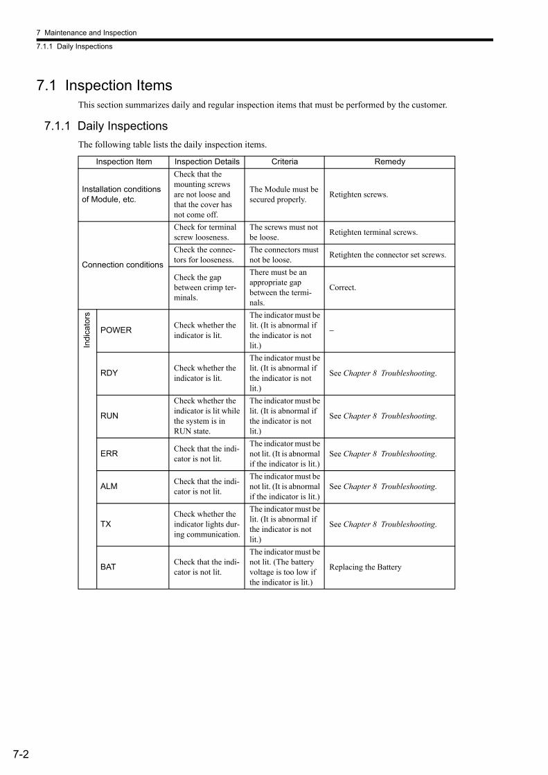
7 Maintenance and Inspection
7.1.1 Daily Inspections
7-2
7.1 Inspection ItemsThis section summarizes daily and regular inspection items that must be performed by the customer.
7.1.1 Daily InspectionsThe following table lists the daily inspection items.
Inspection Item Inspection Details Criteria Remedy
Installation conditions of Module, etc.
Check that the mounting screws are not loose and that the cover has not come off.
The Module must be secured properly. Retighten screws.
Connection conditions
Check for terminal screw looseness.
The screws must not be loose. Retighten terminal screws.
Check the connec-tors for looseness.
The connectors must not be loose. Retighten the connector set screws.
Check the gap between crimp ter-minals.
There must be an appropriate gap between the termi-nals.
Correct.
Indi
cato
rs
POWER Check whether the indicator is lit.
The indicator must be lit. (It is abnormal if the indicator is not lit.)
−
RDY Check whether the indicator is lit.
The indicator must be lit. (It is abnormal if the indicator is not lit.)
See Chapter 8 Troubleshooting.
RUN
Check whether the indicator is lit while the system is in RUN state.
The indicator must be lit. (It is abnormal if the indicator is not lit.)
See Chapter 8 Troubleshooting.
ERR Check that the indi-cator is not lit.
The indicator must be not lit. (It is abnormal if the indicator is lit.)
See Chapter 8 Troubleshooting.
ALM Check that the indi-cator is not lit.
The indicator must be not lit. (It is abnormal if the indicator is lit.)
See Chapter 8 Troubleshooting.
TXCheck whether the indicator lights dur-ing communication.
The indicator must be lit. (It is abnormal if the indicator is not lit.)
See Chapter 8 Troubleshooting.
BAT Check that the indi-cator is not lit.
The indicator must be not lit. (The battery voltage is too low if the indicator is lit.)
Replacing the Battery
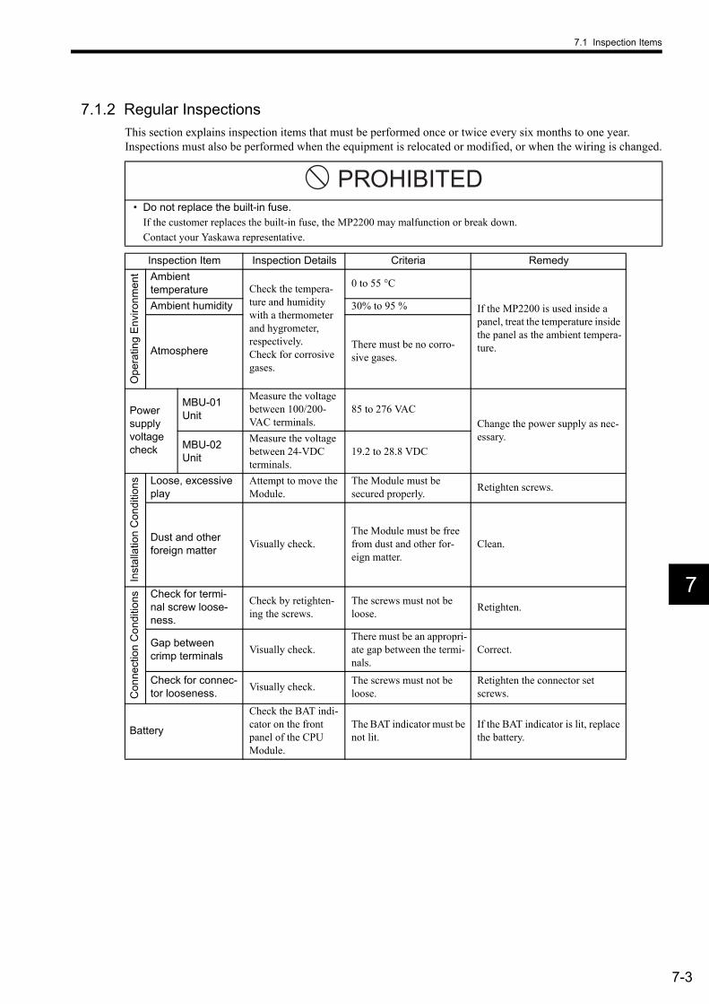
7.1 Inspection Items
7-3
7
7.1.2 Regular InspectionsThis section explains inspection items that must be performed once or twice every six months to one year. Inspections must also be performed when the equipment is relocated or modified, or when the wiring is changed.
• Do not replace the built-in fuse.If the customer replaces the built-in fuse, the MP2200 may malfunction or break down.Contact your Yaskawa representative.
Inspection Item Inspection Details Criteria Remedy
Ope
ratin
g En
viro
nmen
t Ambient temperature Check the tempera-
ture and humidity with a thermometer and hygrometer, respectively.Check for corrosive gases.
0 to 55 °C
If the MP2200 is used inside a panel, treat the temperature inside the panel as the ambient tempera-ture.
Ambient humidity 30% to 95 %
Atmosphere There must be no corro-sive gases.
Power supply voltage check
MBU-01 Unit
Measure the voltage between 100/200-VAC terminals.
85 to 276 VACChange the power supply as nec-essary.
MBU-02 Unit
Measure the voltage between 24-VDC terminals.
19.2 to 28.8 VDC
Inst
alla
tion
Con
ditio
ns Loose, excessive play
Attempt to move the Module.
The Module must be secured properly. Retighten screws.
Dust and other foreign matter Visually check.
The Module must be free from dust and other for-eign matter.
Clean.
Con
nect
ion
Con
ditio
ns Check for termi-nal screw loose-ness.
Check by retighten-ing the screws.
The screws must not be loose. Retighten.
Gap between crimp terminals Visually check.
There must be an appropri-ate gap between the termi-nals.
Correct.
Check for connec-tor looseness. Visually check. The screws must not be
loose.Retighten the connector set screws.
Battery
Check the BAT indi-cator on the front panel of the CPU Module.
The BAT indicator must be not lit.
If the BAT indicator is lit, replace the battery.
PROHIBITED

7 Maintenance and Inspection
7.2.1 Battery Life
7-4
7.2 MBU-01/MBU-02 Unit BatteriesMBU-01 and MBU-02 Units have a built-in, replaceable battery. This battery is used to back up data to prevent the data stored in the CPU Module memory from being lost when power is interrupted (e.g., when the power sup-ply to the MBU-01 or MBU-02 Unit is turned OFF).
7.2.1 Battery LifeThe built-in battery can retain the contents of the memory until the total time of power interruptions reaches one year. The warranty period of the battery is five years from the date of purchase. These values, however, differ according to the operating conditions, including the ambient temperature.Always replace the battery with a replacement battery (ZZK000064) within two weeks after the CPU Module BAT indicator first lights. Any delay in battery replacement will result in the data stored in the memory being lost.
7.2.2 Replacing the BatteryThis section explains how to replace the battery.
(1) Preparations(a) Saving the Memory Contents
Before replacing the battery, save the programs and data from the memory of the CPU Module to floppy disks or a hard disk. The saved programs and data will be used if the programs and data are accidentally deleted during battery replacement.
(b) Preparing a Replacement BatteryPrepare a replacement battery (ZZK000064). This battery is not commercially available, and must be ordered from your nearest Yaskawa sales representative. The appearance of the battery is illustrated below.
ZZK000064 (Battery with Cable)
(2) Replacing the BatteryUse the following procedure to replace the battery.
1. Check that the MBU-01/MBU-02 Unit POWER indicator is lit.
2. Open the battery cover on the front of the MBU-01/MBU-02 Unit.
3. Disconnect the battery cable from the connector on the MBU-01/MBU-02 Unit, then remove the built-in battery from the battery holder.
4. Firmly connect the replacement battery cable to the connector on the MBU-01/MBU-02 Unit. Then, place the replacement battery into the battery holder.
5. Make sure that the BAT indicator on the CPU Module is not lit.
6. Close the cover.This completes the battery replacement procedure.
Be sure to replace the battery with the power supply to the MBU-01/MBU-02 Unit turned ON.Replacing the battery with the power supply to the MBU-01/MBU-02 Unit turned OFF will result in the pro-grams and data stored in the CPU Module memory being lost.
LiTHIUM
Black lead Red lead
IMPORTANT
8-1
8
8Troubleshooting
This chapter describes the errors that can occur when using the MP2200 system, their probable causes and the appropriate countermeasures.
8.1 Overview of Troubleshooting - - - - - - - - - - - - - - - - - - - - - - - - - - - - - - - - - 8-28.1.1 Troubleshooting Methods - - - - - - - - - - - - - - - - - - - - - - - - - - - - - - - - - - - - - - - - - - - - 8-28.1.2 Basic Troubleshooting Flow - - - - - - - - - - - - - - - - - - - - - - - - - - - - - - - - - - - - - - - - - - 8-38.1.3 Indicator Errors - - - - - - - - - - - - - - - - - - - - - - - - - - - - - - - - - - - - - - - - - - - - - - - - - - - 8-3
8.2 System Errors - - - - - - - - - - - - - - - - - - - - - - - - - - - - - - - - - - - - - - - - - - - 8-58.2.1 Overview of System Errors - - - - - - - - - - - - - - - - - - - - - - - - - - - - - - - - - - - - - - - - - - - 8-58.2.2 Processing Flow When a System Error Occurs - - - - - - - - - - - - - - - - - - - - - - - - - - - - 8-68.2.3 Processing Flow for a User Program Error - - - - - - - - - - - - - - - - - - - - - - - - - - - - - - - - 8-78.2.4 System Register Configuration - - - - - - - - - - - - - - - - - - - - - - - - - - - - - - - - - - - - - - - - 8-8

8 Troubleshooting
8.1.1 Troubleshooting Methods
8-2
8.1 Overview of TroubleshootingThis section shows the basic troubleshooting flow and provides a list of errors.
8.1.1 Troubleshooting MethodsThere are three checks available for checking the system when an errors occurs. They are checks by symptoms, error codes, and monitor functions of peripheral devices. Checking procedures are categorized by status condi-tions to help determine the cause quickly.
(1) Checking by SymptomsFactors like indicators on the front of the Module and the control status of all devices are visually checked to determine a cause and implement corrections.
(2) Checking by Error CodesError codes generated when errors occur are monitored to determine a cause and implement corrections.Errors are classified as follows:
(3) Checking by Monitor Functions of Peripheral DevicesThe monitor functions of peripheral devices are used to determine the control status and to find the cause of errors. The status of the following functions can be checked.
• Program monitoring• Position monitoring• Error monitoring• Tracing
Classification Type of Error CodeSequence Control Error Code
System (S) registers:SW00040 onwards
Motion Control Error Code Error in SERVOPACK

8.1 Overview of Troubleshooting
8-3
8
8.1.2 Basic Troubleshooting FlowWhen a problem occurs, it is important to determine the cause and treat the problem fast to get the system up and running as quickly as possible. The following table shows the basic troubleshooting flow.
8.1.3 Indicator ErrorsError details can be checked by the status of indicators on the front of the MP2200 Module.In the process, we narrow down the repair location in a program by getting an overview of the error from indica-tors, checking the contents of the system (S) registers, examining the drawing or function number that caused the error and then getting an overview of operation error details.
(1) IndicatorsThe LED indicators that display the operating status and error details for the MP2200 are detailed in the follow-ing table.
Point Basic Details Examined
Visual Check
• Equipment operation (status while stopped)• Power ON/OFF• I/O equipment status• Wiring status• Status of indicators (indicators on all Modules)• Status of all switches (DIP switches and other switches)• Parameters and program content check
Error Check
Observe whether the following alters the error in any way.• Stopping the MP2200.• Resetting the alarm.• Turning the power OFF and ON.
Narrowing the Range
Consider possible failure locations based on the results of 1 and 2 above.• Is the problem in the MP2200 or external?• Is the problem in sequence control or motion control?• Is the problem software or hardware?
Indicators Indicator Name
Indicator Color Significance when Lit
RDY Green Unit operating normally.RUN Green User program running.ALM Red Lights/blinks for warning.ERR Red Lights/blinks for failures.BAT Red Battery alarm occurred.
RDY
ERR
RUN
ALM
BAT
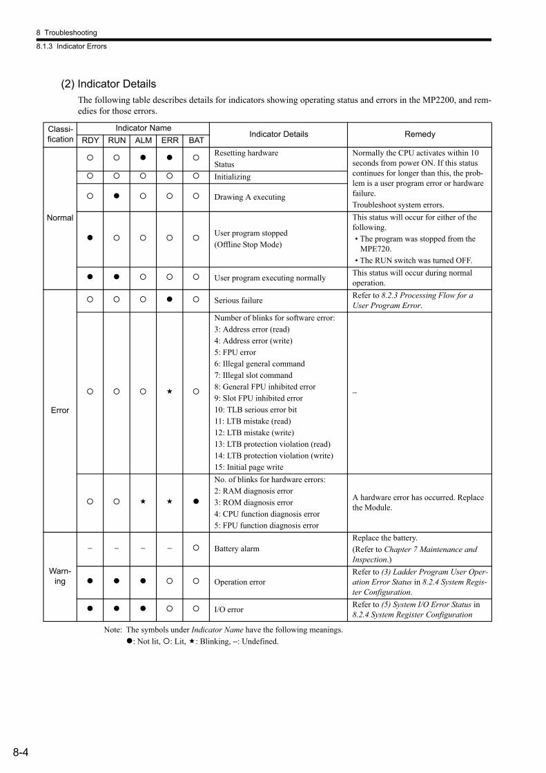
8 Troubleshooting
8.1.3 Indicator Errors
8-4
(2) Indicator DetailsThe following table describes details for indicators showing operating status and errors in the MP2200, and rem-edies for those errors.
Note: The symbols under Indicator Name have the following meanings.: Not lit, : Lit, : Blinking, −: Undefined.
Classi-fication
Indicator NameIndicator Details Remedy
RDY RUN ALM ERR BAT
Normal
Resetting hardwareStatus
Normally the CPU activates within 10 seconds from power ON. If this status continues for longer than this, the prob-lem is a user program error or hardware failure.Troubleshoot system errors.
Initializing
Drawing A executing
User program stopped(Offline Stop Mode)
This status will occur for either of the following.• The program was stopped from the
MPE720.• The RUN switch was turned OFF.
User program executing normally This status will occur during normal operation.
Error
Serious failure Refer to 8.2.3 Processing Flow for a User Program Error.
Number of blinks for software error:3: Address error (read)4: Address error (write)5: FPU error6: Illegal general command7: Illegal slot command8: General FPU inhibited error9: Slot FPU inhibited error10: TLB serious error bit11: LTB mistake (read)12: LTB mistake (write)13: LTB protection violation (read)14: LTB protection violation (write)15: Initial page write
−
No. of blinks for hardware errors:2: RAM diagnosis error3: ROM diagnosis error4: CPU function diagnosis error5: FPU function diagnosis error
A hardware error has occurred. Replace the Module.
Warn-ing
− − − − Battery alarmReplace the battery.(Refer to Chapter 7 Maintenance and Inspection.)
Operation errorRefer to (3) Ladder Program User Oper-ation Error Status in 8.2.4 System Regis-ter Configuration.
I/O error Refer to (5) System I/O Error Status in 8.2.4 System Register Configuration

8.2 System Errors
8-5
8
8.2 System ErrorsThis section explains system error details and remedies.
8.2.1 Overview of System ErrorsIndicators on the front panel of the CPU Module indicate the operating and error status of the MP2200. Use the system (S) registers to get for more details on errors. Carefully check system register details to figure out the fail-ure location and implement corrections. The following sections describes the system register in more detail.
(1) System Register AllocationThe following illustration shows the configuration of the system registers.
(2) Viewing System RegistersUse the Quick Reference function or the Register List function from the MPE720.
SW00000 System Service RegisterSW00030 System StatusSW00050 System Error StatusSW00080 User Operation Error StatusSW00090 System Service Execution StatusSW00110 User Operation Error Status, DetailsSW00190 Alarm Counter and Alarm ClearSW00200 System I/O Error StatusSW00500 Reserved by the system.SW00698 Interrupt StatusSW00800 Module InformationSW01312 Reserved by the system.SW02048 Reserved by the system.SW03200 Motion Program InformationSW05200 Reserved by the system.SW05264 to SW08191 Reserved by the system.
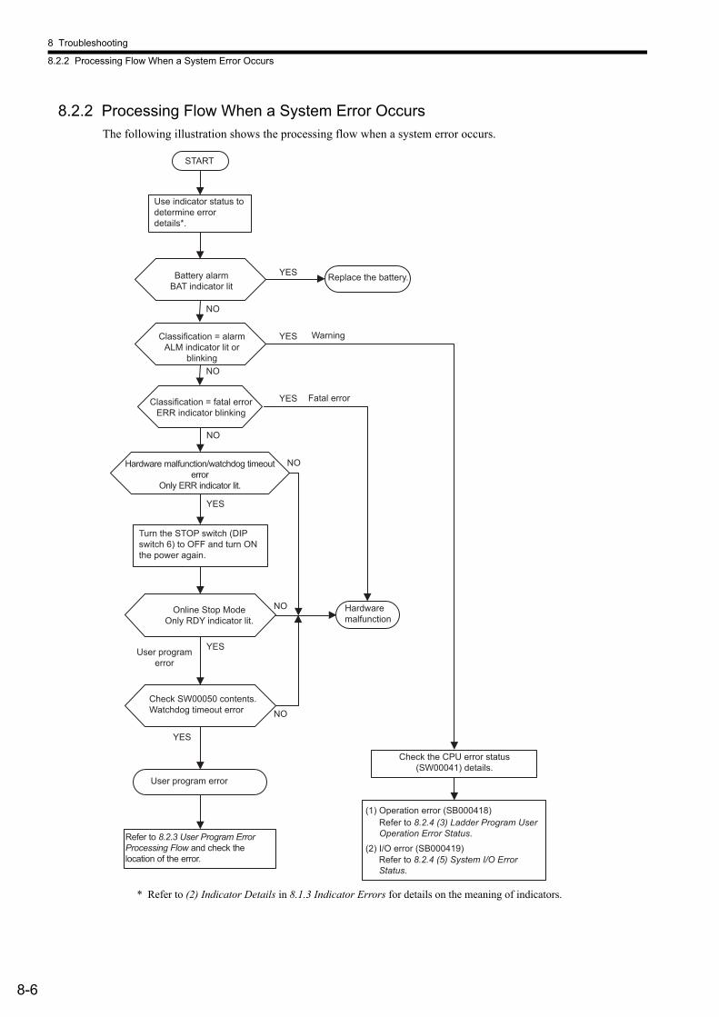
8 Troubleshooting
8.2.2 Processing Flow When a System Error Occurs
8-6
8.2.2 Processing Flow When a System Error OccursThe following illustration shows the processing flow when a system error occurs.
* Refer to (2) Indicator Details in 8.1.3 Indicator Errors for details on the meaning of indicators.
START
NO
YES
NO
NO
YES
YES
YES
NO
NO
YES
YES
NO
Use indicator status to determine error details*.
Classification = alarmALM indicator lit or
blinking
Classification = fatal errorERR indicator blinking
Hardware malfunction/watchdog timeout error
Only ERR indicator lit.
Online Stop ModeOnly RDY indicator lit.
Check SW00050 contents.Watchdog timeout error
User program error
Refer to 8.2.3 User Program Error Processing Flow and check the location of the error.
Hardware malfunction
Check the CPU error status (SW00041) details.
(1) Operation error (SB000418)Refer to 8.2.4 (3) Ladder Program User Operation Error Status.
(2) I/O error (SB000419)Refer to 8.2.4 (5) System I/O Error Status.
User program error
Battery alarm BAT indicator lit
Replace the battery.
Fatal error
Warning
Turn the STOP switch (DIP switch 6) to OFF and turn ON the power again.

8.2 System Errors
8-7
8
8.2.3 Processing Flow for a User Program Error(1) Processing Flow for a Ladder Program Error
A serious failure has occurred if the ALM and ERR indicators on the front panel of the CPU Module are lit. Place the MP2200 in Stop Status (turn ON DIP switch pin 6) and investigate the problem.Use the following procedures to check the error.
↑|||||
Check by Type of Serious Failure Check the contents of SW00050 (Error Type) to determine if the error is a system error or a user program error.
Check by Type of Error Program Check the contents of SW00055 (Program Type) to determine if the error occurred in a drawing or in a function.
Whe
n ER
R In
dica
tor L
it
Check by Error Drawing Check the contents of SW00054 (Error Task) and SW00056 (Drawing No.) to find the error drawing.
||||↓
Check by Error Function
The error occurred in a function if SW00056 (Drawing No.) reads 0100H.Check the contents of SW00057 (Error Task) and SW00058 (Drawing No.) to find the error drawing.Check SW00059 (Function Referencing Drawing Step No.) for the STEP number where an operation error occurred.
↑|||||
Check Whether an Operation Error Oc-curred
Check the error count of all drawings at SW00080 to SW00088. Operation errors are occurring if the count is going up.
Whe
n AL
M In
dica
tor L
it
Check the Details and Location of Op-eration Errors
If an operation error occurs, the 00 (H00, L00, i00, and A00) drawings will ex-ecute. These drawings can also be used to correct or confirm operation.
1. Check Error DetailsCheck error codes for drawings where the error count is going up.DWG.A: SW00111 DWG.H: SW00143DWG.I: SW00127 DWG.L: SW00175
2. Check the DWG NumberCheck the error DWG number for the DWG number where an error occurred.DWG.A: SW00122 DWG.H: SW00154DWG.I: SW00138 DWG.L: SW00186
3. Check the Function Referencing DWG Number and Function Refer-encing STEP Number if an error occurred in a function. DWG.A: SW00123, 4 DWG.H: SW00155, 6 DWG.I: SW00139, 40 DWG.L: SW00187, 8
||||↓
Correct the Program. Correct the program at the point where the error occurred.
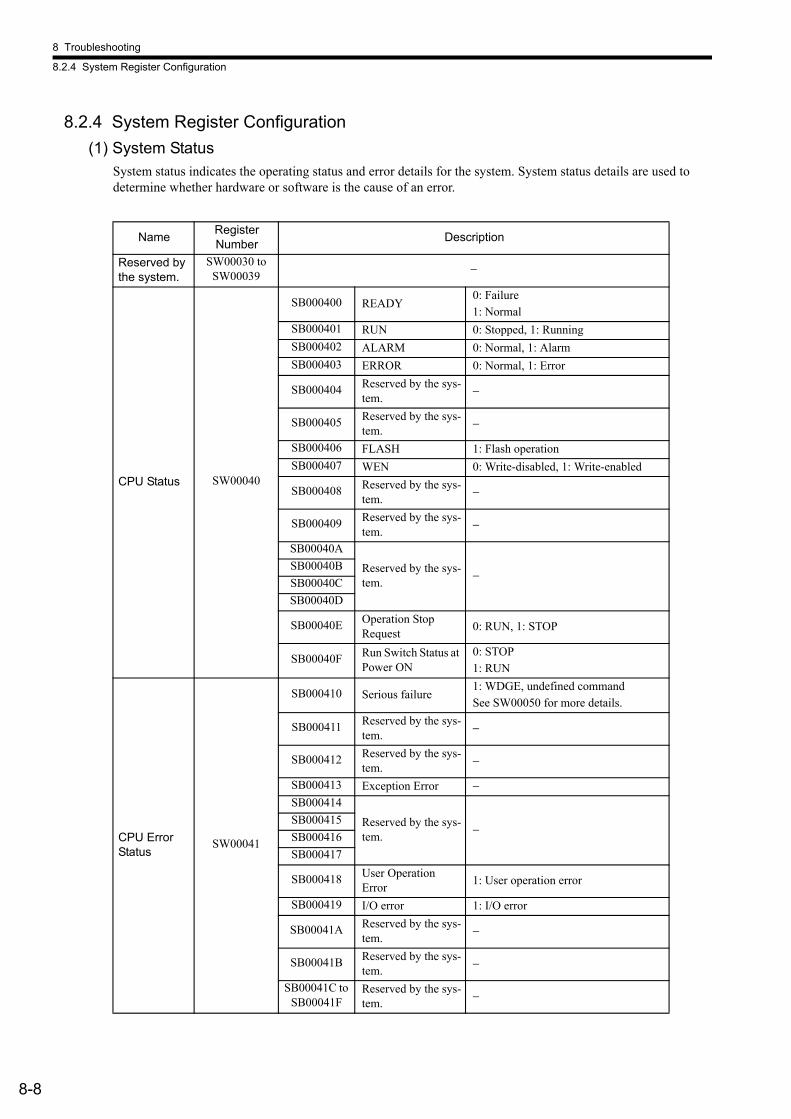
8 Troubleshooting
8.2.4 System Register Configuration
8-8
8.2.4 System Register Configuration(1) System Status
System status indicates the operating status and error details for the system. System status details are used to determine whether hardware or software is the cause of an error.
Name Register Number Description
Reserved by the system.
SW00030 to SW00039 −
CPU Status SW00040
SB000400 READY0: Failure1: Normal
SB000401 RUN 0: Stopped, 1: RunningSB000402 ALARM 0: Normal, 1: AlarmSB000403 ERROR 0: Normal, 1: Error
SB000404 Reserved by the sys-tem. −
SB000405 Reserved by the sys-tem. −
SB000406 FLASH 1: Flash operationSB000407 WEN 0: Write-disabled, 1: Write-enabled
SB000408 Reserved by the sys-tem. −
SB000409 Reserved by the sys-tem. −
SB00040A
Reserved by the sys-tem. −
SB00040BSB00040CSB00040D
SB00040E Operation Stop Request 0: RUN, 1: STOP
SB00040F Run Switch Status at Power ON
0: STOP1: RUN
CPU Error Status
SW00041
SB000410 Serious failure1: WDGE, undefined commandSee SW00050 for more details.
SB000411 Reserved by the sys-tem. −
SB000412 Reserved by the sys-tem. −
SB000413 Exception Error −SB000414
Reserved by the sys-tem. −
SB000415SB000416SB000417
SB000418 User Operation Error 1: User operation error
SB000419 I/O error 1: I/O error
SB00041A Reserved by the sys-tem. −
SB00041B Reserved by the sys-tem. −
SB00041C to SB00041F
Reserved by the sys-tem. −

8.2 System Errors
8-9
8
Reserved by the system.
SW00047
SB000470 Reserved by the sys-tem. −
SB000471SB000472
Reserved by the sys-tem. −
SB000473 Reserved by the sys-tem. −
SB000474 Reserved by the sys-tem. −
SB000475 Reserved by the sys-tem. −
SB000476 to SB00047F
Reserved by the sys-tem. −
Hardware Status Configuration
SW00048
SB000480 TEST
DIP switch status0: ON, 1: OFF
SB000481 MONSB000482 CNFGSB000483 INITSB000484 SUPSB000485 STOPSB000486 Å|SB000487 Battery alarm −
SB000488 to SB00048E
Reserved by the sys-tem. −
SB00048F Reserved by the sys-tem. −
Reserved by the system.
SW00049 SW000490 to SW00049F
Reserved by the sys-tem. −
(cont’d)
Name Register Number Description
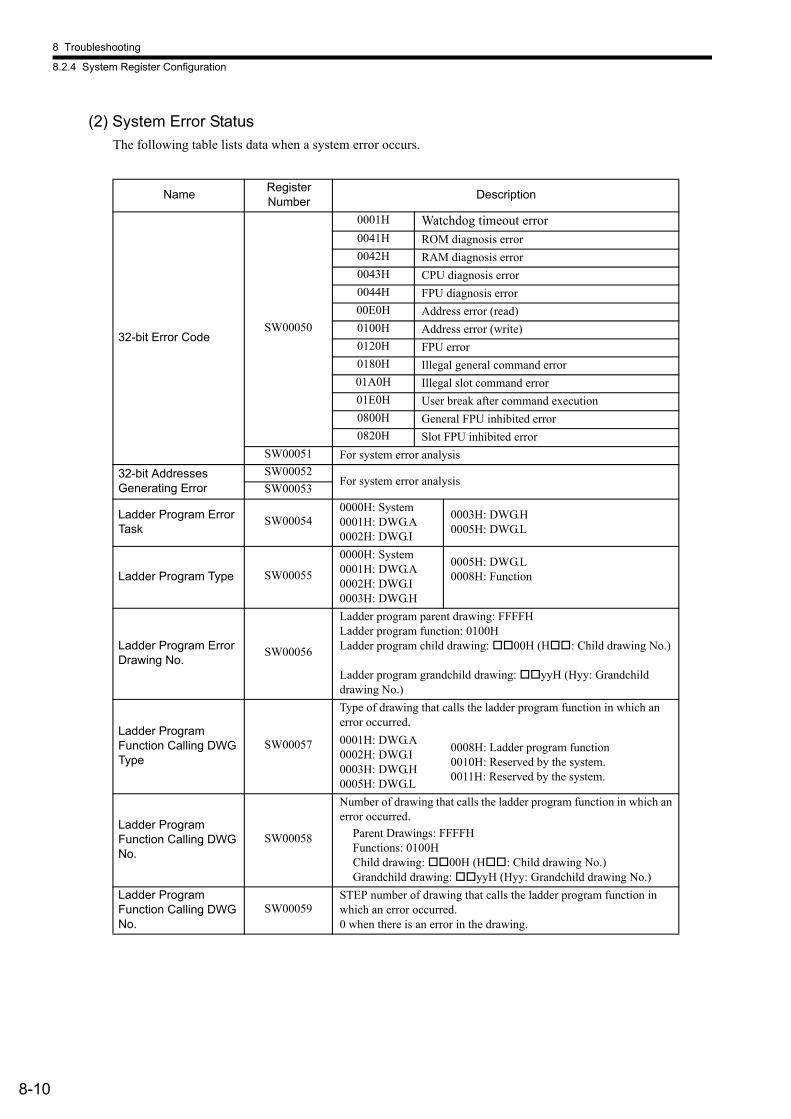
8 Troubleshooting
8.2.4 System Register Configuration
8-10
(2) System Error StatusThe following table lists data when a system error occurs.
Name Register Number Description
32-bit Error CodeSW00050
0001H Watchdog timeout error0041H ROM diagnosis error0042H RAM diagnosis error0043H CPU diagnosis error0044H FPU diagnosis error00E0H Address error (read)0100H Address error (write)0120H FPU error0180H Illegal general command error01A0H Illegal slot command error01E0H User break after command execution0800H General FPU inhibited error0820H Slot FPU inhibited error
SW00051 For system error analysis32-bit Addresses Generating Error
SW00052For system error analysisSW00053
Ladder Program Error Task
SW000540000H: System0001H: DWG.A0002H: DWG.I
0003H: DWG.H0005H: DWG.L
Ladder Program Type SW00055
0000H: System0001H: DWG.A0002H: DWG.I0003H: DWG.H
0005H: DWG.L0008H: Function
Ladder Program Error Drawing No.
SW00056
Ladder program parent drawing: FFFFHLadder program function: 0100HLadder program child drawing: 00H (H : Child drawing No.) Ladder program grandchild drawing: yyH (Hyy: Grandchild drawing No.)
Ladder Program Function Calling DWG Type
SW00057
Type of drawing that calls the ladder program function in which an error occurred.0001H: DWG.A0002H: DWG.I0003H: DWG.H0005H: DWG.L
0008H: Ladder program function0010H: Reserved by the system.0011H: Reserved by the system.
Ladder Program Function Calling DWG No.
SW00058
Number of drawing that calls the ladder program function in which an error occurred.
Parent Drawings: FFFFHFunctions: 0100HChild drawing: 00H (H : Child drawing No.)Grandchild drawing: yyH (Hyy: Grandchild drawing No.)
Ladder Program Function Calling DWG No.
SW00059STEP number of drawing that calls the ladder program function in which an error occurred.0 when there is an error in the drawing.
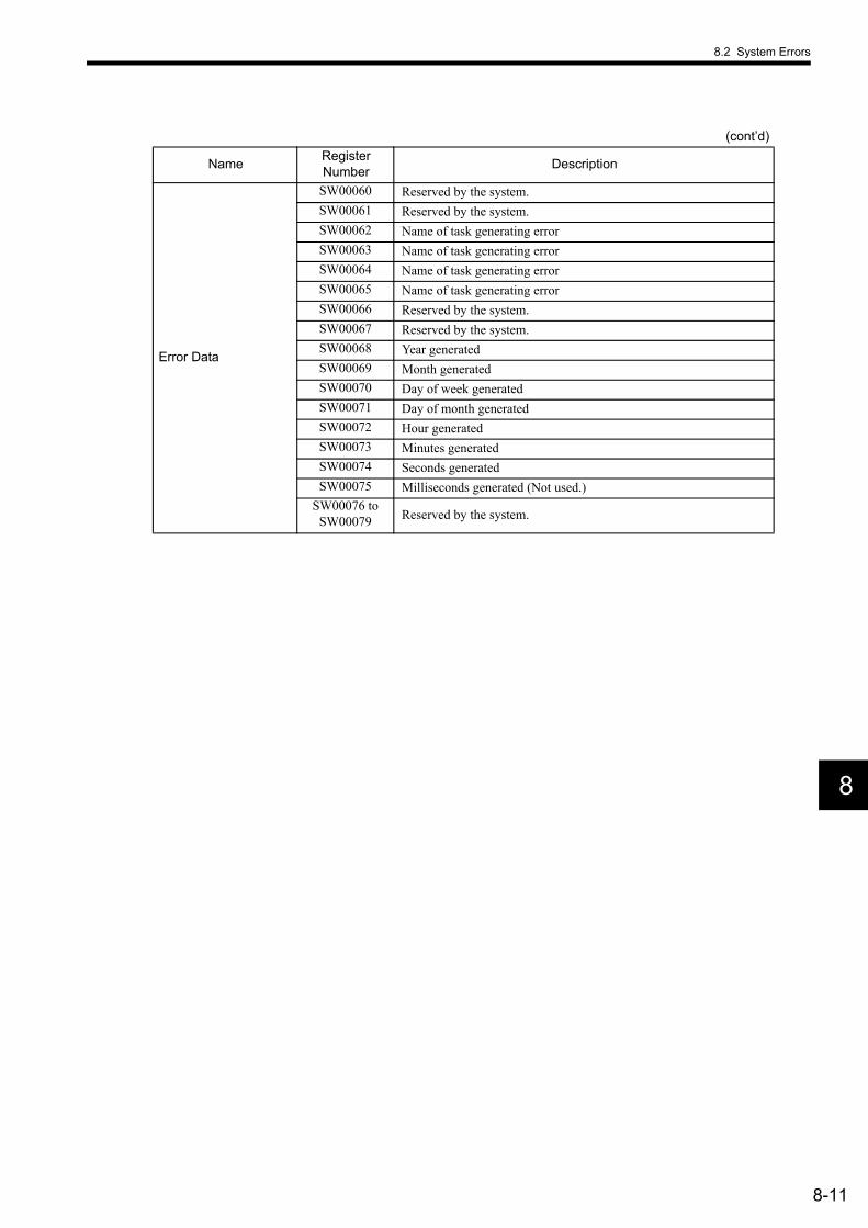
8.2 System Errors
8-11
8
Error Data
SW00060 Reserved by the system.SW00061 Reserved by the system.SW00062 Name of task generating errorSW00063 Name of task generating errorSW00064 Name of task generating errorSW00065 Name of task generating errorSW00066 Reserved by the system.SW00067 Reserved by the system.SW00068 Year generatedSW00069 Month generatedSW00070 Day of week generatedSW00071 Day of month generatedSW00072 Hour generatedSW00073 Minutes generatedSW00074 Seconds generatedSW00075 Milliseconds generated (Not used.)
SW00076 to SW00079 Reserved by the system.
(cont’d)
Name Register Number Description
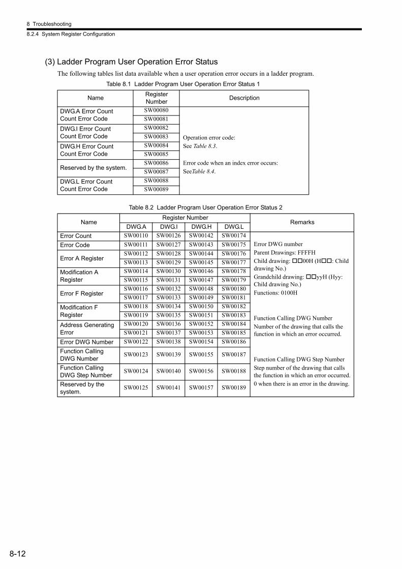
8 Troubleshooting
8.2.4 System Register Configuration
8-12
(3) Ladder Program User Operation Error StatusThe following tables list data available when a user operation error occurs in a ladder program.
Table 8.1 Ladder Program User Operation Error Status 1
Name Register Number Description
DWG.A Error CountCount Error Code
SW00080
Operation error code:See Table 8.3.
Error code when an index error occurs:SeeTable 8.4.
SW00081
DWG.I Error CountCount Error Code
SW00082SW00083
DWG.H Error CountCount Error Code
SW00084SW00085
Reserved by the system.SW00086SW00087
DWG.L Error CountCount Error Code
SW00088SW00089
Table 8.2 Ladder Program User Operation Error Status 2
NameRegister Number
RemarksDWG.A DWG.I DWG.H DWG.L
Error Count SW00110 SW00126 SW00142 SW00174Error DWG numberParent Drawings: FFFFHChild drawing: 00H (H : Child drawing No.)Grandchild drawing: yyH (Hyy: Child drawing No.)Functions: 0100H
Function Calling DWG NumberNumber of the drawing that calls the function in which an error occurred.
Function Calling DWG Step NumberStep number of the drawing that calls the function in which an error occurred.0 when there is an error in the drawing.
Error Code SW00111 SW00127 SW00143 SW00175
Error A RegisterSW00112 SW00128 SW00144 SW00176SW00113 SW00129 SW00145 SW00177
Modification A Register
SW00114 SW00130 SW00146 SW00178SW00115 SW00131 SW00147 SW00179
Error F RegisterSW00116 SW00132 SW00148 SW00180SW00117 SW00133 SW00149 SW00181
Modification F Register
SW00118 SW00134 SW00150 SW00182SW00119 SW00135 SW00151 SW00183
Address Generating Error
SW00120 SW00136 SW00152 SW00184SW00121 SW00137 SW00153 SW00185
Error DWG Number SW00122 SW00138 SW00154 SW00186Function Calling DWG Number
SW00123 SW00139 SW00155 SW00187
Function Calling DWG Step Number
SW00124 SW00140 SW00156 SW00188
Reserved by the system.
SW00125 SW00141 SW00157 SW00189

8.2 System Errors
8-13
8
* Yes: Can be set to value other than system default from the user program. No: The system default cannot be changed from the user program.
Table 8.3 Ladder Program User Operation Error Status -3Error Code Error Contents User* System Default
Inte
ger O
pera
tion
0001H Integer operation - underflow Yes −32768 [−32768]0002H Integer operation - overflow Yes 32767 [32767]0003H Integer operation - division error Yes The A register remains the same.
0009H Double-length integer operation - underflow
Yes −2147483648 [−2147483648]
000AH Double-length integer operation - overflow
Yes 2147483647 [2147483647]
000BH Double-length integer operation - division error
Yes The A register remains the same.
010 H Operation error drawing - integer operation error ( = 1 to B)
No Default indicated above.
Rea
l Num
ber O
pera
tion
0010H Integer storage - non-numeric error Yes Store not executed. [00000]0011H Integer storage - underflow Yes Store not executed. [−32768]0012H Integer storage - overflow Yes Store not executed. [+32767]0021H Real number storage - underflow Yes Store not executed. [−1.0E+38]0022H Real number storage - overflow Yes Store not executed. [1.0E+38]
0023H Real number operation - division-by-zero error
Yes Operation not executed. The F register remains the same.
0030H Real number operation - invalid opera-tion (non-numeric)
No Operation not executed.
0031H Real number operation - exponent underflow
No 0.0
0032H Real number operation - exponent over-flow
No Maximum value
0033H Real number operation - division error (non-numeric 0/0)
No Operation not executed.
0034H Real number storage - exponent under-flow
No Stores 0.0.
0035H Real number operation - stack error − −
0040H to 0059H
Standard System Functions Real number operation errors
No Interrupt operation and output = 0.0
0040H: SQRT 0041H: SIN 0042H: COS 0043H: TAN0044H: ASIN 0045H: ACOS 0046H: ATAN 0047H: EXP0048H: LN 0049H: LOG 004AH: DZA 004BH: DZB004CH: LIM 004DH: PI 004EH: PD 004FH: PID0050H: LAG 0051H: LLAG 0053H: FGN 0054H: IFGN0054H: LAU 0055H: SLAU 0056H: REM 0057H: RCHK0058H: BSRCH 0059H: SQRT − −
1000H or 2000H is added for an index error.
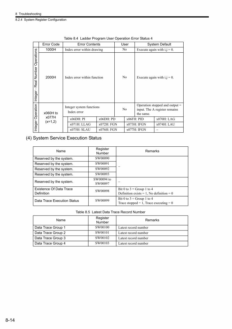
8 Troubleshooting
8.2.4 System Register Configuration
8-14
(4) System Service Execution Status
Table 8.4 Ladder Program User Operation Error Status 4Error Code Error Contents User System Default
Inte
ger -
Rea
l Num
ber O
pera
tions 1000H Index error within drawing No Execute again with i,j = 0.
2000H Index error within function No Execute again with i,j = 0.
Inte
ger O
pera
tion
x060H to x077H (x=1,2)
Integer system functionsIndex error
NoOperation stopped and output = input. The A register remains the same.
x06DH: PI x06DH: PD x06FH: PID x070H: LAGx071H: LLAG x072H: FGN x073H: IFGN x074H: LAUx075H: SLAU x076H: FGN x077H: IFGN −
Name Register Number Remarks
Reserved by the system. SW00090
−Reserved by the system. SW00091Reserved by the system. SW00092Reserved by the system. SW00093
Reserved by the system.SW00094 to
SW00097 −
Existence Of Data Trace Definition
SW00098 Bit 0 to 3 = Group 1 to 4Definition exists = 1, No definition = 0
Data Trace Execution Status SW00099 Bit 0 to 3 = Group 1 to 4Trace stopped = 1, Trace executing = 0
Table 8.5 Latest Data Trace Record Number
Name Register Number Remarks
Data Trace Group 1 SW00100 Latest record numberData Trace Group 2 SW00101 Latest record numberData Trace Group 3 SW00102 Latest record numberData Trace Group 4 SW00103 Latest record number
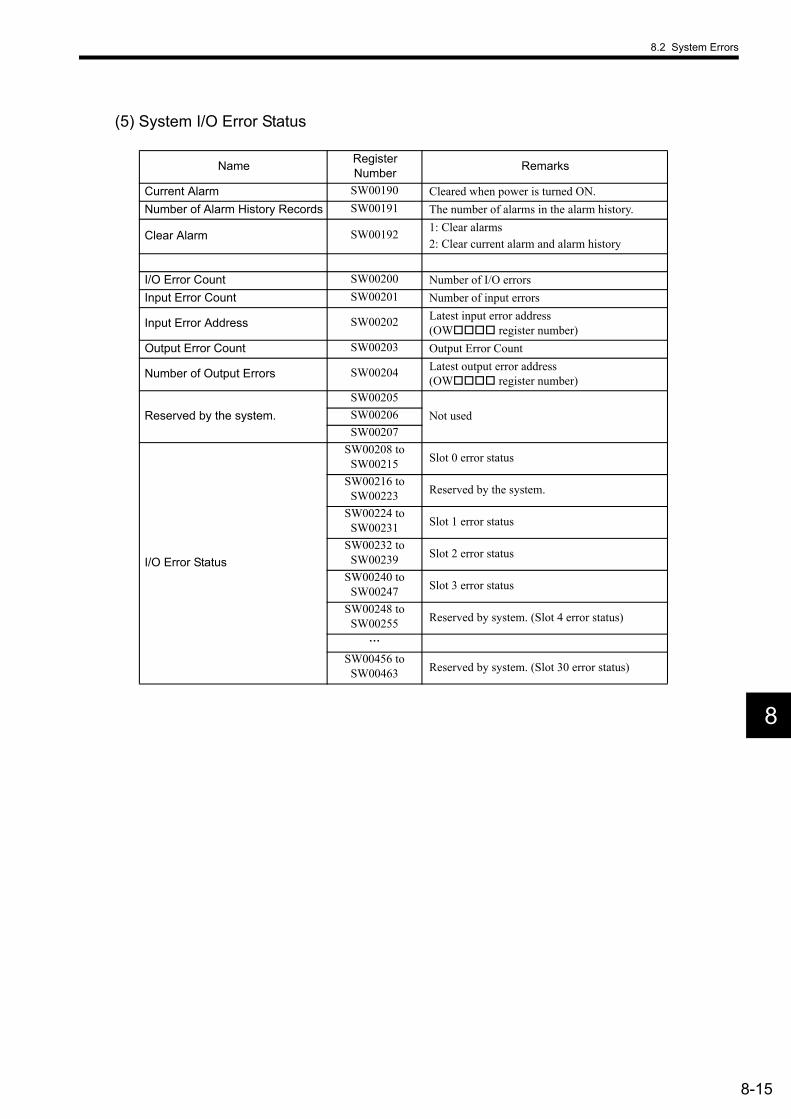
8.2 System Errors
8-15
8
(5) System I/O Error Status
Name Register Number Remarks
Current Alarm SW00190 Cleared when power is turned ON.Number of Alarm History Records SW00191 The number of alarms in the alarm history.
Clear Alarm SW00192 1: Clear alarms2: Clear current alarm and alarm history
I/O Error Count SW00200 Number of I/O errorsInput Error Count SW00201 Number of input errors
Input Error Address SW00202 Latest input error address (OW register number)
Output Error Count SW00203 Output Error Count
Number of Output Errors SW00204 Latest output error address (OW register number)
Reserved by the system.SW00205
Not usedSW00206SW00207
I/O Error Status
SW00208 to SW00215 Slot 0 error status
SW00216 to SW00223 Reserved by the system.
SW00224 to SW00231 Slot 1 error status
SW00232 to SW00239 Slot 2 error status
SW00240 to SW00247 Slot 3 error status
SW00248 to SW00255 Reserved by system. (Slot 4 error status)
SW00456 to SW00463 Reserved by system. (Slot 30 error status)
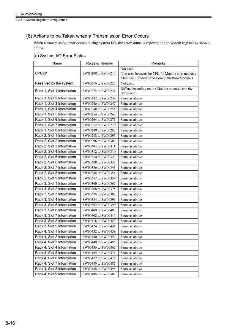
8 Troubleshooting
8.2.4 System Register Configuration
8-16
(6) Actions to be Taken when a Transmission Error OccursWhen a transmission error occurs during system I/O, the error status is reported in the system register as shown below.
(a) System I/O Error StatusName Register Number Remarks
CPU-01 SW00208 to SW00215Not used.(Not used because the CPU-01 Module does not have a built-in I/O Module or Communication Module.)
Reserved by the system. SW00216 to SW00223 Not used.
Rack 1, Slot 1 Information SW00224 to SW00231 Differs depending on the Module mounted and the error code.
Rack 1, Slot 2 Information SW00232 to SW00239 Same as above. Rack 1, Slot 3 Information SW00240 to SW00247 Same as above. Rack 1, Slot 4 Information SW00248 to SW00255 Same as above. Rack 1, Slot 5 Information SW00256 to SW00263 Same as above. Rack 1, Slot 6 Information SW00264 to SW00271 Same as above. Rack 1, Slot 7 Information SW00272 to SW00279 Same as above. Rack 1, Slot 8 Information SW00280 to SW00287 Same as above. Rack 2, Slot 1 Information SW00288 to SW00295 Same as above. Rack 2, Slot 2 Information SW00296 to SW00303 Same as above. Rack 2, Slot 3 Information SW00304 to SW00311 Same as above. Rack 2, Slot 4 Information SW00312 to SW00319 Same as above. Rack 2, Slot 5 Information SW00320 to SW00327 Same as above. Rack 2, Slot 6 Information SW00328 to SW00335 Same as above. Rack 2, Slot 7 Information SW00336 to SW00343 Same as above. Rack 2, Slot 8 Information SW00344 to SW00351 Same as above. Rack 2, Slot 9 Information SW00352 to SW00359 Same as above. Rack 3, Slot 1 Information SW00360 to SW00367 Same as above. Rack 3, Slot 2 Information SW00368 to SW00375 Same as above. Rack 3, Slot 3 Information SW00376 to SW00383 Same as above. Rack 3, Slot 4 Information SW00384 to SW00391 Same as above. Rack 3, Slot 5 Information SW00392 to SW00399 Same as above. Rack 3, Slot 6 Information SW00400 to SW00407 Same as above. Rack 3, Slot 7 Information SW00408 to SW00415 Same as above. Rack 3, Slot 8 Information SW00416 to SW00423 Same as above. Rack 3, Slot 9 Information SW00424 to SW00431 Same as above. Rack 4, Slot 1 Information SW00432 to SW00439 Same as above. Rack 4, Slot 2 Information SW00440 to SW00447 Same as above. Rack 4, Slot 3 Information SW00448 to SW00455 Same as above. Rack 4, Slot 4 Information SW00456 to SW00463 Same as above. Rack 4, Slot 5 Information SW00464 to SW00471 Same as above. Rack 4, Slot 6 Information SW00472 to SW00479 Same as above. Rack 4, Slot 7 Information SW00480 to SW00487 Same as above. Rack 4, Slot 8 Information SW00488 to SW00495 Same as above. Rack 4, Slot 9 Information SW00496 to SW00503 Same as above.

8.2 System Errors
8-17
8
(b) I/O Error Status, Applicable Modules
• SVB-01 Module Error StatusExample: Rack 1, Slot 1
Table 8.6 Error Status Details
Subslot No. The number displayed in the Module Details section in the Module Definition Window.
Classification Abbreviation Applicable RemarksCPU Module CPU-01 No No external I/O interface
Motion ModulesSVA-01
No Refer to the monitor parameters for error information.
SVB-01 Yes
Communication Modules
217IF-01 No No I/O218IF-01 No No I/O260IF-01 Yes261IF-01 Yes
I/O ModulesLIO-01 YesLIO-02 YesLIO-04 Yes
Expansion I/O Modules EXIOIF No
F 8 7 0 (Bit No.)SW00224 Status Subslot (function) No.1
F 2 1 0 (Bit No.)
SW00225 ST#15 ST#2 ST#1 Not used.
F E D
SW00226 Not used. ST#30 ST#29 ST#17 ST#16
SW00227 Not used.
SW00228 Not used.
SW00229 Not used.
SW00230 Not used.
SW00231 Not used.
Item Code Remarks Subslot No. 1 1 = SVB-01 (MECHATROLINK communications)
Status 0 Normal 1 Station error
ST#n0 Communication normal 1 Communication error at "n" station
(When set to slave, n is the local station number.)
TERMS

8 Troubleshooting
8.2.4 System Register Configuration
8-18
• 260IF-01 Module Error Status
Example: Rack 1, Slot 1
Table 8.7 Error Status Details
F 8 7 0 (Bit No.)SW00224 Status Subslot (function) No.
F 2 1 0 (Bit No.)SW00225 ST#15 ST#2 ST#1 ST#0
F E DSW00226 ST#31 ST#17 ST#16
SW00227 ST#47 ST#33 ST#32
SW00228 ST#63 ST#49 ST#48
SW00229 Not used.
SW00230 Not used.
SW00231 Not used.
Item Code Remarks
Subslot No. 2 2 = 260IF (DeviceNet)
Note: 1 = 217IF (RS-232C)
Status 0 Normal 1 Station error
ST#n0 Communications normal 1 Communication error at "n" station
(When set to slave, n is the local station number.)
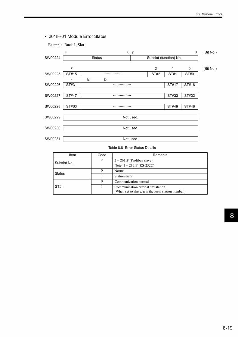
8.2 System Errors
8-19
8
• 261IF-01 Module Error Status
Example: Rack 1, Slot 1
Table 8.8 Error Status Details
F 8 7 0 (Bit No.)SW00224 Status Subslot (function) No.
F 2 1 0 (Bit No.)SW00225 ST#15 ST#2 ST#1 ST#0
F E DSW00226 ST#31 ST#17 ST#16
SW00227 ST#47 ST#33 ST#32
SW00228 ST#63 ST#49 ST#48
SW00229 Not used.
SW00230 Not used.
SW00231 Not used.
Item Code Remarks
Subslot No. 2 2 = 261IF (Profibus slave)
Note: 1 = 217IF (RS-232C)
Status 0 Normal 1 Station error
ST#n0 Communication normal 1 Communication error at "n" station
(When set to slave, n is the local station number.)

8 Troubleshooting
8.2.4 System Register Configuration
8-20
• LIO-01 Module Error Status
Example: Rack 1, Slot 1
Table 8.9 Error Status Details
* CNTR error information (PG burnout) is reflected in the input registers.
F 8 7 0 (Bit No.)SW00224 Status Subslot (function)No.
SW00225 Not used.
SW00226 Not used.
SW00227 Not used.
SW00228 Not used.
SW00229 Not used.
SW00230 Not used.
SW00231 Not used.
Item Code Remarks
Subslot No. 1 1 = LIO (DI: 16 points, DO: 16 points (sink mode))
Note: 2 = CNTR* (counter)
Status 0 Normal 2 I/O error (Output fuse burnout)

8.2 System Errors
8-21
8
• LIO-02 Module Error Status
Example: Rack 1, Slot 1
Table 8.10 Error Status Details
* CNTR error information (PG burnout) is reflected in the input registers.
F 8 7 0 (Bit No.)SW00224 Status Subslot (function) No.
SW00225 Not used.
SW00226 Not used.
SW00227 Not used.
SW00228 Not used.
SW00229 Not used.
SW00230 Not used.
SW00231 Not used.
Item Code Remarks
Subslot No. 1 1 = LIO (DI: 16 points, DO: 16 points (source mode))
Note: 2 = CNTR* (counter)
Status 0 Normal 2 I/O error (Output fuse burnout)

8 Troubleshooting
8.2.4 System Register Configuration
8-22
• LIO-04 Module Error Status
Example: Rack 1, Slot 1
Table 8.11 Error Status Details
F 8 7 0 (Bit No.)SW00224 Status Subslot (function) No.
SW00225 Not used.
SW00226 Not used.
SW00227 Not used.
SW00228 Not used.
SW00229 Not used.
SW00230 Not used.
SW00231 Not used.
Item Code Remarks Subslot No. 1 1 = LIO (DI: 32 points, DO: 32 points (sink mode))
Status 0 Normal 2 I/O error (Output fuse burnout)
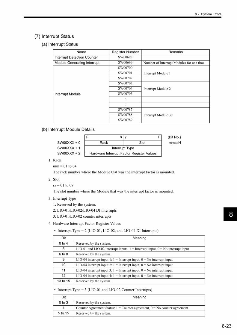
8.2 System Errors
8-23
8
(7) Interrupt Status(a) Interrupt Status
(b) Interrupt Module Details
1. Rack mm = 01 to 04The rack number where the Module that was the interrupt factor is mounted.
2. Slot ss = 01 to 09The slot number where the Module that was the interrupt factor is mounted.
3. Interrupt Type 1: Reserved by the system. 2: LIO-01/LIO-02/LIO-04 DI interrupts3: LIO-01/LIO-02 counter interrupts
4. Hardware Interrupt Factor Register Values
• Interrupt Type = 2 (LIO-01, LIO-02, and LIO-04 DI Interrupts)
• Interrupt Type = 3 (LIO-01 and LIO-02 Counter Interrupts)
Name Register Number Remarks Interrupt Detection Counter SW00698Module Generating Interrupt SW00699 Number of Interrupt Modules for one time
Interrupt Module
SW00700Interrupt Module 1SW00701
SW00702SW00703
Interrupt Module 2SW00704SW00705
: :
SW00787Interrupt Module 30SW00788
SW00789
F 8 7 0 (Bit No.)SW00XXX + 0 Rack Slot mmssHSW00XXX + 1 Interrupt Type SW00XXX + 2 Hardware Interrupt Factor Register Values
Bit Meaning 0 to 4 Reserved by the system.
5 LIO-01 and LIO-02 interrupt inputs: 1 = Interrupt input, 0 = No interrupt input 6 to 8 Reserved by the system.
9 LIO-04 interrupt input 1: 1 = Interrupt input, 0 = No interrupt input 10 LIO-04 interrupt input 2: 1 = Interrupt input, 0 = No interrupt input 11 LIO-04 interrupt input 3: 1 = Interrupt input, 0 = No interrupt input 12 LIO-04 interrupt input 4: 1 = Interrupt input, 0 = No interrupt input
13 to 15 Reserved by the system.
Bit Meaning 0 to 3 Reserved by the system.
4 Counter Agreement Status: 1 = Counter agreement, 0 = No counter agreement5 to 15 Reserved by the system.
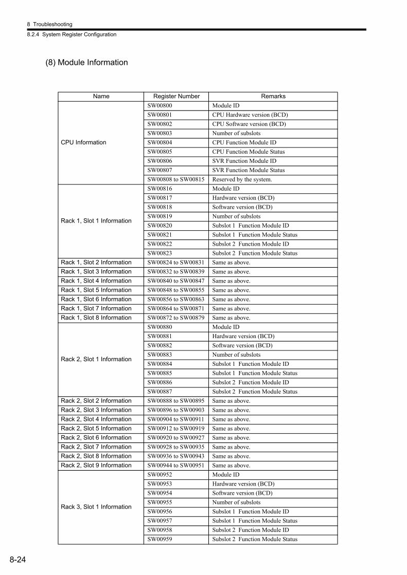
8 Troubleshooting
8.2.4 System Register Configuration
8-24
(8) Module Information
Name Register Number Remarks
CPU Information
SW00800 Module IDSW00801 CPU Hardware version (BCD)SW00802 CPU Software version (BCD)SW00803 Number of subslotsSW00804 CPU Function Module IDSW00805 CPU Function Module Status SW00806 SVR Function Module IDSW00807 SVR Function Module Status SW00808 to SW00815 Reserved by the system.
Rack 1, Slot 1 Information
SW00816 Module IDSW00817 Hardware version (BCD)SW00818 Software version (BCD)SW00819 Number of subslotsSW00820 Subslot 1 Function Module IDSW00821 Subslot 1 Function Module Status SW00822 Subslot 2 Function Module IDSW00823 Subslot 2 Function Module Status
Rack 1, Slot 2 Information SW00824 to SW00831 Same as above. Rack 1, Slot 3 Information SW00832 to SW00839 Same as above. Rack 1, Slot 4 Information SW00840 to SW00847 Same as above. Rack 1, Slot 5 Information SW00848 to SW00855 Same as above. Rack 1, Slot 6 Information SW00856 to SW00863 Same as above. Rack 1, Slot 7 Information SW00864 to SW00871 Same as above. Rack 1, Slot 8 Information SW00872 to SW00879 Same as above.
Rack 2, Slot 1 Information
SW00880 Module IDSW00881 Hardware version (BCD)SW00882 Software version (BCD)SW00883 Number of subslotsSW00884 Subslot 1 Function Module IDSW00885 Subslot 1 Function Module Status SW00886 Subslot 2 Function Module IDSW00887 Subslot 2 Function Module Status
Rack 2, Slot 2 Information SW00888 to SW00895 Same as above. Rack 2, Slot 3 Information SW00896 to SW00903 Same as above. Rack 2, Slot 4 Information SW00904 to SW00911 Same as above. Rack 2, Slot 5 Information SW00912 to SW00919 Same as above. Rack 2, Slot 6 Information SW00920 to SW00927 Same as above. Rack 2, Slot 7 Information SW00928 to SW00935 Same as above. Rack 2, Slot 8 Information SW00936 to SW00943 Same as above. Rack 2, Slot 9 Information SW00944 to SW00951 Same as above.
Rack 3, Slot 1 Information
SW00952 Module IDSW00953 Hardware version (BCD)SW00954 Software version (BCD)SW00955 Number of subslotsSW00956 Subslot 1 Function Module IDSW00957 Subslot 1 Function Module Status SW00958 Subslot 2 Function Module IDSW00959 Subslot 2 Function Module Status
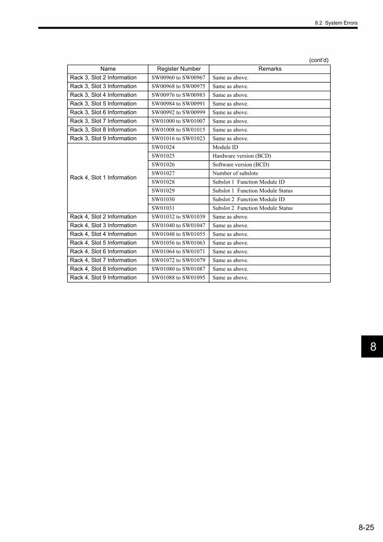
8.2 System Errors
8-25
8
Rack 3, Slot 2 Information SW00960 to SW00967 Same as above. Rack 3, Slot 3 Information SW00968 to SW00975 Same as above. Rack 3, Slot 4 Information SW00976 to SW00983 Same as above. Rack 3, Slot 5 Information SW00984 to SW00991 Same as above. Rack 3, Slot 6 Information SW00992 to SW00999 Same as above. Rack 3, Slot 7 Information SW01000 to SW01007 Same as above. Rack 3, Slot 8 Information SW01008 to SW01015 Same as above. Rack 3, Slot 9 Information SW01016 to SW01023 Same as above.
Rack 4, Slot 1 Information
SW01024 Module IDSW01025 Hardware version (BCD)SW01026 Software version (BCD)SW01027 Number of subslotsSW01028 Subslot 1 Function Module IDSW01029 Subslot 1 Function Module Status SW01030 Subslot 2 Function Module IDSW01031 Subslot 2 Function Module Status
Rack 4, Slot 2 Information SW01032 to SW01039 Same as above. Rack 4, Slot 3 Information SW01040 to SW01047 Same as above. Rack 4, Slot 4 Information SW01048 to SW01055 Same as above. Rack 4, Slot 5 Information SW01056 to SW01063 Same as above. Rack 4, Slot 6 Information SW01064 to SW01071 Same as above. Rack 4, Slot 7 Information SW01072 to SW01079 Same as above. Rack 4, Slot 8 Information SW01080 to SW01087 Same as above. Rack 4, Slot 9 Information SW01088 to SW01095 Same as above.
(cont’d)Name Register Number Remarks

A-1
AAppendices
A List of System Registers - - - - - - - - - - - - - - - - - - - - - - - - - - - - - - - - - - - - A-2A.1 System Service Registers - - - - - - - - - - - - - - - - - - - - - - - - - - - - - - - - - - - - - - - - - - - - A-2A.2 Scan Execution Status and Calendar - - - - - - - - - - - - - - - - - - - - - - - - - - - - - - - - - - - - A-5A.3 Program Software Numbers and Remaining Program Memory Capacity - - - - - - - - - - - A-5
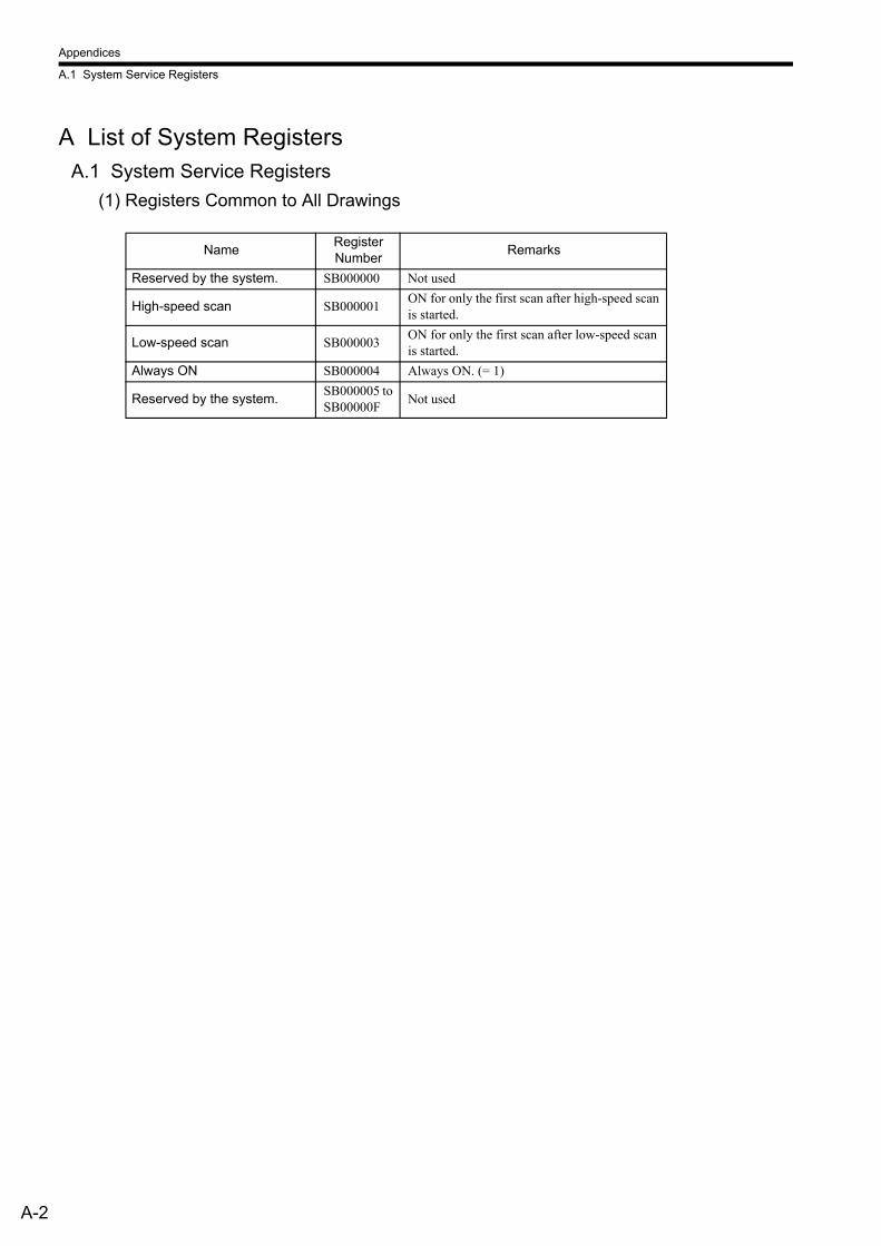
Appendices
A.1 System Service Registers
A-2
A List of System RegistersA.1 System Service Registers
(1) Registers Common to All Drawings
Name Register Number Remarks
Reserved by the system. SB000000 Not used
High-speed scan SB000001 ON for only the first scan after high-speed scan is started.
Low-speed scan SB000003 ON for only the first scan after low-speed scan is started.
Always ON SB000004 Always ON. (= 1)
Reserved by the system. SB000005 to SB00000F Not used

A List of System Registers
A-3
A
(2) Registers Specific to High-speed Scan DrawingsThese registers are set when high-speed scan starts.
Name Register Number Remarks
1-scan Flicker Relay SB000010
0.5-s Flicker Relay SB000011
1.0-s Flicker Relay SB000012
2.0-s Flicker Relay SB000013
0.5-s Sampling Relay SB000014
1.0-s Sampling Relay SB000015
2.0-s Sampling Relay SB000016
60.0-s Sampling Relay SB000017
1.0 s After Start of Scan Relay SB000018
2.0 s After Start of Scan Relay SB000019
5.0 s After Start of Scan Relay SB00001A
1 scan
1 scan
0.5 s 0.5 s
1.0 s 1.0 s
2.0 s 2.0 s
0.5 s 0.5 s
1 scan
1.0 s 1.0 s
1 scan
2.0 s 2.0 s
1 scan
60.0 s 60.0 s
1 scan
1.0 s
2.0 s
5.0 s
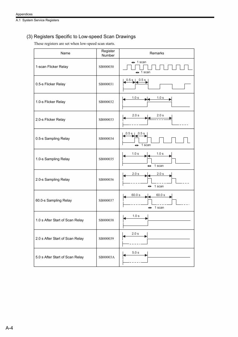
Appendices
A.1 System Service Registers
A-4
(3) Registers Specific to Low-speed Scan DrawingsThese registers are set when low-speed scan starts.
Name Register Number Remarks
1-scan Flicker Relay SB000030
0.5-s Flicker Relay SB000031
1.0-s Flicker Relay SB000032
2.0-s Flicker Relay SB000033
0.5-s Sampling Relay SB000034
1.0-s Sampling Relay SB000035
2.0-s Sampling Relay SB000036
60.0-s Sampling Relay SB000037
1.0 s After Start of Scan Relay SB000038
2.0 s After Start of Scan Relay SB000039
5.0 s After Start of Scan Relay SB00003A
1 scan
1 scan
0.5 s 0.5 s
1.0 s 1.0 s
2.0 s 2.0 s
0.5 s 0.5 s
1 scan
1.0 s 1.0 s
1 scan
2.0 s 2.0 s
1 scan
60.0 s 60.0 s
1 scan
1.0 s
2.0 s
5.0 s

A List of System Registers
A-5
A
A.2 Scan Execution Status and Calendar
A.3 Program Software Numbers and Remaining Program Memory Capacity
Name Register Number Remarks
High-speed Scan Set Value SW00004 High-speed Scan Set Value (0.1 ms)High-speed Scan Current Value SW00005 High-speed Scan Current Value (0.1 ms)High-speed Scan Maximum Value SW00006 High-speed Scan Maximum Value (0.1 ms)
Reserved by the system. SW00007 to SW00009 Not used
Low-speed Scan Set Value SW00010 Low-speed Scan Set Value (0.1 ms)Low-speed Scan Current Value SW00011 Low-speed Scan Current Value (0.1 ms)Low-speed Scan Maximum Value SW00012 Low-speed Scan Maximum Value (0.1 ms)Reserved by the system. SW00013 Not usedExecuting Scan Current Value SW00014 Executing Scan Current Value (0.1 ms)Calendar: Year SW00015 1999: 0099 (BCD) (Last two digits only)Calendar: Month Day SW00016 December 31: 1231 (BCD)Calendar: Hours Minutes SW00017 23 hours 59 minutes: 2359 (BCD)Calendar: Seconds SW00018 59 s: 59 (BCD)Calendar: Day of Week SW00019 0 to 6: Sun., Mon. to Sat.
Name Register Number Remarks
System Program Software Number SW00020 S ( is stored as BCD)
System Number SW00021 to SW00025 Not used
Remaining Program Memory Capacity SW00026 In bytesTotal Module Memory Capacity SW00028 In bytes
Index
Index-1
INDEX
Symbols# registers- - - - - - - - - - - - - - - - - - - - - - - - - - - - - - - - - - - - - - 6-23
Numerics217IF-01 Module- - - - - - - - - - - - - - - - - - - - - - - - - - - - - - - - - 4-45
connectors - - - - - - - - - - - - - - - - - - - - - - - - - - - - - - - - - - 5-51offline self-diagnostic test - - - - - - - - - - - - - - - - - - - - - - - - 4-46
218IF-01 Module- - - - - - - - - - - - - - - - - - - - - - - - - - - - - - - - - 4-42connectors - - - - - - - - - - - - - - - - - - - - - - - - - - - - - - - - - - 5-47
24-V input connector - - - - - - - - - - - - - - - - - - - - - - - - - - - - - - 5-18260IF-01 Module- - - - - - - - - - - - - - - - - - - - - - - - - - - - - - - - - 4-48
connectors - - - - - - - - - - - - - - - - - - - - - - - - - - - - - - - - - - 5-55error status - - - - - - - - - - - - - - - - - - - - - - - - - - - - - - - - - - 8-18
261IF-01 Module- - - - - - - - - - - - - - - - - - - - - - - - - - - - - - - - - 4-52connectors - - - - - - - - - - - - - - - - - - - - - - - - - - - - - - - - - - 5-58error status - - - - - - - - - - - - - - - - - - - - - - - - - - - - - - - - - - 8-19offline self-diagnostic test - - - - - - - - - - - - - - - - - - - - - - - - 4-53
AA drawings - - - - - - - - - - - - - - - - - - - - - - - - - - - - - - - - - - - - - - 6-7all program file dump - - - - - - - - - - - - - - - - - - - - - - - - - - - - - - 3-33all program file transfer - - - - - - - - - - - - - - - - - - - - - - - - - - - - 3-23
BBase Unit - - - - - - - - - - - - - - - - - - - - - - - - - - - - - - - - - - - - - - - 4-5Basic Module
appearance - - - - - - - - - - - - - - - - - - - - - - - - - - - - - - - 1-3, 4-57indicator patterns - - - - - - - - - - - - - - - - - - - - - - - - - - - - - - - 6-4
batterybattery life - - - - - - - - - - - - - - - - - - - - - - - - - - - - - - - - - - - 7-4replacing - - - - - - - - - - - - - - - - - - - - - - - - - - - - - - - - - - - - 7-4
Cchild drawings- - - - - - - - - - - - - - - - - - - - - - - - - - - - - - - - - - - - 6-7coincidence output and coincidence interrupt functions - - - - - - - 4-31communication settings - - - - - - - - - - - - - - - - - - - - - - - - - - - - 3-12constant registers - - - - - - - - - - - - - - - - - - - - - - - - - - - - - - - - - 6-23controller folders
creating - - - - - - - - - - - - - - - - - - - - - - - - - - - - - - - - - - - - 3-18counter function
axis type selection - - - - - - - - - - - - - - - - - - - - - - - - - - - - - 4-36command settings - - - - - - - - - - - - - - - - - - - - - - - - - - - - - 4-38counter monitor parameters - - - - - - - - - - - - - - - - - - - - - - - 4-39counter setting parameters- - - - - - - - - - - - - - - - - - - - - - - - 4-38fixed parameters - - - - - - - - - - - - - - - - - - - - - - - - - - - - - - 4-37status - - - - - - - - - - - - - - - - - - - - - - - - - - - - - - - - - - - - - - 4-39
counter interrupts- - - - - - - - - - - - - - - - - - - - - - - - - - - - - - - - - 8-23CPU functions and specifications comparison - - - - - - - - - - - - - 4-10CPU RUN settings- - - - - - - - - - - - - - - - - - - - - - - - - - - - - - - - 3-34CPU-01 Module - - - - - - - - - - - - - - - - - - - - - - - - - - - - - - - - - - 4-7
DD registers - - - - - - - - - - - - - - - - - - - - - - - - - - - - - - - - - - - - - 6-23daily inspections - - - - - - - - - - - - - - - - - - - - - - - - - - - - - - - - - - 7-2data registers- - - - - - - - - - - - - - - - - - - - - - - - - - - - - - - - - - - - 6-23data types - - - - - - - - - - - - - - - - - - - - - - - - - - - - - - - - - - - - - - 6-20DeviceNet communications specifications - - - - - - - - - - - - - - - - 4-51DeviceNet interface - - - - - - - - - - - - - - - - - - - - - - - - - - - - - - - 4-48DI interrupts - - - - - - - - - - - - - - - - - - - - - - - - - - - - - - - - - - - - 8-23DIN rail - - - - - - - - - - - - - - - - - - - - - - - - - - - - - - - - - - - - - - - - 5-2
DIN rail mounting clips - - - - - - - - - - - - - - - - - - - - - - - - - - - - - 5-3drawings - - - - - - - - - - - - - - - - - - - - - - - - - - - - - - - - - - - - - - - 6-7
execution control - - - - - - - - - - - - - - - - - - - - - - - - - - - - - - 6-8execution processing method - - - - - - - - - - - - - - - - - - - - - 6-10execution scheduling - - - - - - - - - - - - - - - - - - - - - - - - - - - - 6-8hierarchical arrangement - - - - - - - - - - - - - - - - - - - - - - - - - 6-9types - - - - - - - - - - - - - - - - - - - - - - - - - - - - - - - - - - - - - - - 6-7
DWG registers - - - - - - - - - - - - - - - - - - - - - - - - - - - - - - - - - - 6-23
Eelectronic gear
function - - - - - - - - - - - - - - - - - - - - - - - - - - - - - - - - - - - - 4-33Ethernet communications specifications - - - - - - - - - - - - - - - - - 4-44Ethernet interface - - - - - - - - - - - - - - - - - - - - - - - - - - - - - - - - 4-42Ethernet settings - - - - - - - - - - - - - - - - - - - - - - - - - - - - - - - - - 3-15EXIOIF Module
connectors - - - - - - - - - - - - - - - - - - - - - - - - - - - - - - - - - - 5-61
Fflash memory
saving to - - - - - - - - - - - - - - - - - - - - - - - - - - - - - - - - - - - 3-31function registers- - - - - - - - - - - - - - - - - - - - - - - - - - - - - - - - - 6-24functions - - - - - - - - - - - - - - - - - - - - - - - - - - - - - - - - - - - 6-7, 6-19functions and specifications
CPU-01 Module - - - - - - - - - - - - - - - - - - - - - - - - - - - - - - 4-10
Ggrandchild drawings - - - - - - - - - - - - - - - - - - - - - - - - - - - - - - - 6-7group folders
creating - - - - - - - - - - - - - - - - - - - - - - - - - - - - - - - - - - - - 3-17
HH drawings- - - - - - - - - - - - - - - - - - - - - - - - - - - - - - - - - - 3-40, 6-7H01 drawing - - - - - - - - - - - - - - - - - - - - - - - - - - - - - - - - - - - 3-41H02 drawing - - - - - - - - - - - - - - - - - - - - - - - - - - - - - - - - - - - 3-42H02.01 drawing - - - - - - - - - - - - - - - - - - - - - - - - - - - - - - - - - 3-43H02.02 drawing - - - - - - - - - - - - - - - - - - - - - - - - - - - - - - - - - 3-45H06.01 drawing - - - - - - - - - - - - - - - - - - - - - - - - - - - - - - - - - 3-55H06.02 drawing - - - - - - - - - - - - - - - - - - - - - - - - - - - - - - - - - 3-60handling MP2200 - - - - - - - - - - - - - - - - - - - - - - - - - - - - - - - - - 5-2hardware specifications
217IF-01 Module - - - - - - - - - - - - - - - - - - - - - - - - - - - - - 4-47218IF-01 Module - - - - - - - - - - - - - - - - - - - - - - - - - - - - - 4-44260IF-01 Module - - - - - - - - - - - - - - - - - - - - - - - - - - - - - 4-50261IF-01 Module - - - - - - - - - - - - - - - - - - - - - - - - - - - - - 4-54Base Unit- - - - - - - - - - - - - - - - - - - - - - - - - - - - - - - - - - - - 4-6CPU-01 Module - - - - - - - - - - - - - - - - - - - - - - - - - - - - - - - 4-9EXIOIF Module - - - - - - - - - - - - - - - - - - - - - - - - - - - - - - 4-56LIO-01 Module- - - - - - - - - - - - - - - - - - - - - - - - - - - - - - - 4-24LIO-02 Module- - - - - - - - - - - - - - - - - - - - - - - - - - - - - - - 4-27LIO-04 Module- - - - - - - - - - - - - - - - - - - - - - - - - - - - - - - 4-41MP2200- - - - - - - - - - - - - - - - - - - - - - - - - - - - - - - - - - - - - 4-3SVA-01 Module - - - - - - - - - - - - - - - - - - - - - - - - - - - - - - 4-19SVB-01 Module - - - - - - - - - - - - - - - - - - - - - - - - - - - - - - 4-15
II drawings - - - - - - - - - - - - - - - - - - - - - - - - - - - - - - - - - - - - - - 6-7I/O error status
application modules- - - - - - - - - - - - - - - - - - - - - - - - - - - - 8-17indicator patterns- - - - - - - - - - - - - - - - - - - - - - - - - - - - - - - - - - 8-4initialization
SERVOPACK- - - - - - - - - - - - - - - - - - - - - - - - - - - - - - - - - 3-8system- - - - - - - - - - - - - - - - - - - - - - - - - - - - - - - - - - - - - - 3-8user settings - - - - - - - - - - - - - - - - - - - - - - - - - - - - - - - - - - 3-8
input circuitLIO-01 Module- - - - - - - - - - - - - - - - - - - - - - - - - - - - - - - 5-27

Index
Index-2
LIO-02 Module - - - - - - - - - - - - - - - - - - - - - - - - - - - - - - - 5-33LIO-04 Module - - - - - - - - - - - - - - - - - - - - - - - - - - - - - - - 5-43
input connector24-V - - - - - - - - - - - - - - - - - - - - - - - - - - - - - - - - - - - - - - 5-18
input registers - - - - - - - - - - - - - - - - - - - - - - - - - - - - - - - - - - - 6-23interrupt status - - - - - - - - - - - - - - - - - - - - - - - - - - - - - - - - - - - 8-23
LL drawings - - - - - - - - - - - - - - - - - - - - - - - - - - - - - - - - - -3-63, 6-7L06 drawing - - - - - - - - - - - - - - - - - - - - - - - - - - - - - - - - - - - - 3-63ladder program error processing flow - - - - - - - - - - - - - - - - - - - - 8-7LED
217IF-01 Module - - - - - - - - - - - - - - - - - - - - - - - - - - - - - - 4-45218IF-01 Module - - - - - - - - - - - - - - - - - - - - - - - - - - - - - - 4-43260IF-01 Module - - - - - - - - - - - - - - - - - - - - - - - - - - - - - - 4-4826IF-01 Module- - - - - - - - - - - - - - - - - - - - - - - - - - - - - - - 4-52Base Unit - - - - - - - - - - - - - - - - - - - - - - - - - - - - - - - - - - - - 4-5CPU-01 Module- - - - - - - - - - - - - - - - - - - - - - - - - - - - - - - - 4-7LIO-01 Module - - - - - - - - - - - - - - - - - - - - - - - - - - - - - - - 4-23LIO-02 Module - - - - - - - - - - - - - - - - - - - - - - - - - - - - - - - 4-26LIO-04 Module - - - - - - - - - - - - - - - - - - - - - - - - - - - - - - - 4-40SVA-01 Module- - - - - - - - - - - - - - - - - - - - - - - - - - - - - - - 4-18SVB-01 Module- - - - - - - - - - - - - - - - - - - - - - - - - - - - - - - 4-13
LIO-01 and LIO-02 Modulescounter functions - - - - - - - - - - - - - - - - - - - - - - - - - - - - - - 4-28
LIO-01 Module - - - - - - - - - - - - - - - - - - - - - - - - - - - - - - - - - - 4-22connectors- - - - - - - - - - - - - - - - - - - - - - - - - - - - - - - 5-25, 5-31error status - - - - - - - - - - - - - - - - - - - - - - - - - - - - - - - - - - 8-20
LIO-02 Module - - - - - - - - - - - - - - - - - - - - - - - - - - - - - - - - - - 4-25error status - - - - - - - - - - - - - - - - - - - - - - - - - - - - - - - - - - 8-21
LIO-04 Module - - - - - - - - - - - - - - - - - - - - - - - - - - - - - - - - - - 4-40connection examples- - - - - - - - - - - - - - - - - - - - - - - - - - - - 5-45connector pin arrangement- - - - - - - - - - - - - - - - - - - - - - - - 5-39connectors- - - - - - - - - - - - - - - - - - - - - - - - - - - - - - - - - - - 5-37external I/O cables - - - - - - - - - - - - - - - - - - - - - - - - - - - - - 5-38
logging off - - - - - - - - - - - - - - - - - - - - - - - - - - - - - - - - - - - - - 3-35logging on online - - - - - - - - - - - - - - - - - - - - - - - - - - - - - - - - - 3-19
MMBU-01 Unit
connectors- - - - - - - - - - - - - - - - - - - - - - - - - - - - - - - - - - - - 5-8MBU-02 Unit
connectors- - - - - - - - - - - - - - - - - - - - - - - - - - - - - - - - - - - 5-10MECHATROLINK
list of compatible Modules- - - - - - - - - - - - - - - - - - - - - - - - - 2-6MECHATROLINK connector - - - - - - - - - - - - - - - - - - - - - 5-11MECHATROLINK terminator - - - - - - - - - - - - - - - - - - - - - 5-16MECHATROLINK-compatible SERVOPACKs - - - - - - - - - - 2-6
MECHATROLINK Cable - - - - - - - - - - - - - - - - - - - - - - - - - - - 5-12Module appearance- - - - - - - - - - - - - - - - - - - - - - - - - - - - - - - - - 1-4Module configuration definitions - - - - - - - - - - - - - - - - - - - - - - 6-48
setting/changing- - - - - - - - - - - - - - - - - - - - - - - - - - - - - - - 6-49motion control functions
list - - - - - - - - - - - - - - - - - - - - - - - - - - - - - - - - - - - - - - - - 4-16motion fixed parameters
setting - - - - - - - - - - - - - - - - - - - - - - - - - - - - - - - - - - - - - 3-29motion programs - - - - - - - - - - - - - - - - - - - - - - - - - - - - - 3-47, 6-11
control signals - - - - - - - - - - - - - - - - - - - - - - - - - - - - - - - - 6-14direct designation- - - - - - - - - - - - - - - - - - - - - - - - - - - - - - 6-11execution processing method - - - - - - - - - - - - - - - - - - - - - - 6-13group operation - - - - - - - - - - - - - - - - - - - - - - - - - - - - - - - 6-12indirect designation - - - - - - - - - - - - - - - - - - - - - - - - - - - - 6-11interpolation override - - - - - - - - - - - - - - - - - - - - - - - - - - - 6-15main programs- - - - - - - - - - - - - - - - - - - - - - - - - - - - - - - - 6-11monitoring execution information- - - - - - - - - - - - - - - - - - - 6-15
status - - - - - - - - - - - - - - - - - - - - - - - - - - - - - - - - - - - - - - 6-15subprograms - - - - - - - - - - - - - - - - - - - - - - - - - - - - - - - - - 6-11system work numbers- - - - - - - - - - - - - - - - - - - - - - - - - - - 6-15
MP2200accessories - - - - - - - - - - - - - - - - - - - - - - - - - - - - - - - - - - - 2-7basic system configuration - - - - - - - - - - - - - - - - - - - - - - - - 2-2cables - - - - - - - - - - - - - - - - - - - - - - - - - - - - - - - - - - - - - - 2-7features - - - - - - - - - - - - - - - - - - - - - - - - - - - - - - - - - - - - - 1-2list of Modules - - - - - - - - - - - - - - - - - - - - - - - - - - - - - - - - 2-5mounting - - - - - - - - - - - - - - - - - - - - - - - - - - - - - - - - - - - - 5-2system configuration precautions - - - - - - - - - - - - - - - - - - - - 2-4system startup - - - - - - - - - - - - - - - - - - - - - - - - - - - - - - - - - 3-3
MPE720- - - - - - - - - - - - - - - - - - - - - - - - - - - - - - - - - - - - - - - - 2-8startup - - - - - - - - - - - - - - - - - - - - - - - - - - - - - - - - - - - - - 3-12startup procedure - - - - - - - - - - - - - - - - - - - - - - - - - - - - - - 3-11
multi-drop connections - - - - - - - - - - - - - - - - - - - - - - - - - - - - - 5-57multiple group operation- - - - - - - - - - - - - - - - - - - - - - - - - - - - 6-12
Ooffline self-diagnostic test - - - - - - - - - - - - - - - - - - - - - - - - - - - 4-43offline stop mode- - - - - - - - - - - - - - - - - - - - - - - - - - - - - - - - - - 6-2one group operation - - - - - - - - - - - - - - - - - - - - - - - - - - - - - - - 6-12online logon - - - - - - - - - - - - - - - - - - - - - - - - - - - - - - - - - - - - 3-19online operating mode - - - - - - - - - - - - - - - - - - - - - - - - - - - - - - 6-2online self-diagnosis - - - - - - - - - - - - - - - - - - - - - - - - - - - - - - - 6-6operation error drawings - - - - - - - - - - - - - - - - - - - - - - - - - - - - - 6-7operation start - - - - - - - - - - - - - - - - - - - - - - - - - - - - - - - - - - - - 6-6operation stop - - - - - - - - - - - - - - - - - - - - - - - - - - - - - - - - - - - - 6-6Optional Modules
installing - - - - - - - - - - - - - - - - - - - - - - - - - - - - - - - - - - - - 5-7mounting connectors - - - - - - - - - - - - - - - - - - - - - - - - - - - 4-58removing - - - - - - - - - - - - - - - - - - - - - - - - - - - - - - - - - - - - 5-5replacing and adding - - - - - - - - - - - - - - - - - - - - - - - - - - - - 5-5
order folderscreating - - - - - - - - - - - - - - - - - - - - - - - - - - - - - - - - - - - - 3-18
output circuitLIO-01 Module - - - - - - - - - - - - - - - - - - - - - - - - - - - - - - - 5-28LIO-02 Module - - - - - - - - - - - - - - - - - - - - - - - - - - - - - - - 5-34LIO-04 Module - - - - - - - - - - - - - - - - - - - - - - - - - - - - - - - 5-44
output registers - - - - - - - - - - - - - - - - - - - - - - - - - - - - - - - - - - 6-23
Pparent drawings - - - - - - - - - - - - - - - - - - - - - - - - - - - - - - - - - - - 6-7password - - - - - - - - - - - - - - - - - - - - - - - - - - - - - - - - - - - - - - 3-22PI latch function - - - - - - - - - - - - - - - - - - - - - - - - - - - - - - - - - 4-32pin arrangement
DeviceNet connector - - - - - - - - - - - - - - - - - - - - - - - - - - - 5-56Ethernet connector - - - - - - - - - - - - - - - - - - - - - - - - - - - - - 5-48LIO-01 Module - - - - - - - - - - - - - - - - - - - - - - - - - - - - - - - 5-26LIO-02 Module - - - - - - - - - - - - - - - - - - - - - - - - - - - - - - - 5-32LIO-04 Module - - - - - - - - - - - - - - - - - - - - - - - - - - - - - - - 5-39PORT connector - - - - - - - - - - - - - - - - - - - - - - - - - - - - - - 5-48PROFIBUS connector - - - - - - - - - - - - - - - - - - - - - - - - - - 5-59RS-232C connector - - - - - - - - - - - - - - - - - - - - 5-52, 5-56, 5-59RS-422/485 connector - - - - - - - - - - - - - - - - - - - - - - - - - - 5-52
PLC functions and specifications - - - - - - - - - - - - - - - - - - - - - - - 4-4power supply cable
100 VAC - - - - - - - - - - - - - - - - - - - - - - - - - - - - - - - - - - - - 5-924 VDC - - - - - - - - - - - - - - - - - - - - - - - - - - - - - - - - - - - - 5-10
power supply connections - - - - - - - - - - - - - - - - - - - - - - - - 5-8, 5-10PROFIBUS communications specifications - - - - - - - - - - - - - - - 4-55PROFIBUS ID - - - - - - - - - - - - - - - - - - - - - - - - - - - - - - - - - - 4-55PROFIBUS interface - - - - - - - - - - - - - - - - - - - - - - - - - - - - - - 4-52pulse count function - - - - - - - - - - - - - - - - - - - - - - - - - - - - - - - 4-30pulse counting mode - - - - - - - - - - - - - - - - - - - - - - - - - - - - - - 4-29
Index
Index-3
pulse input circuitLIO-01 Module - - - - - - - - - - - - - - - - - - - - - - - - - - - - - - - 5-29LIO-02 Module - - - - - - - - - - - - - - - - - - - - - - - - - - - - - - - 5-35
Rregister designation methods - - - - - - - - - - - - - - - - - - - - - - - - - 6-26
register number designation- - - - - - - - - - - - - - - - - - - - - - - 6-26symbol designation - - - - - - - - - - - - - - - - - - - - - - - - - - - - 6-26
registers - - - - - - - - - - - - - - - - - - - - - - - - - - - - - - - - - - - - - - - 6-20address- - - - - - - - - - - - - - - - - - - - - - - - - - - - - - - - - - - - - 6-20bit - - - - - - - - - - - - - - - - - - - - - - - - - - - - - - - - - - - - - - - - 6-20double-length integer - - - - - - - - - - - - - - - - - - - - - - - - - - - 6-20integer - - - - - - - - - - - - - - - - - - - - - - - - - - - - - - - - - - - - - 6-20range - - - - - - - - - - - - - - - - - - - - - - - - - - - - - - - - - - - - - - 6-25real number - - - - - - - - - - - - - - - - - - - - - - - - - - - - - - - - - 6-20
regular inspections - - - - - - - - - - - - - - - - - - - - - - - - - - - - - - - - - 7-3RS-232C communication specifications - - - - - - - - - 4-44, 4-50, 4-54RS-422/485 communication specifications - - - - - - - - - - - - - - - 4-47
Ssample programs
individual loading - - - - - - - - - - - - - - - - - - - - - - - - - - - - - 3-26loading- - - - - - - - - - - - - - - - - - - - - - - - - - - - - - - - - - - - - 3-23manual operation - - - - - - - - - - - - - - - - - - - - - - - - - - - - - - 3-36phase control with an electronic cam - - - - - - - - - - - - - - - - 3-57phase control with an electronic shaft - - - - - - - - - - - - - - - - 3-52positioning control - - - - - - - - - - - - - - - - - - - - - - - - - - - - - 3-47
scan times- - - - - - - - - - - - - - - - - - - - - - - - - - - - - - - - - - - - - - 6-48setting and changing - - - - - - - - - - - - - - - - - - - - - - - - - - - 6-48
screw mounting - - - - - - - - - - - - - - - - - - - - - - - - - - - - - - - - - - - 5-2self-configuration - - - - - - - - - - - - - - - - - - - - - - - - - - - - - 6-6, 6-29
217IF-01 Module- - - - - - - - - - - - - - - - - - - - - - - - - - - - - - 6-44218IF-01 Module- - - - - - - - - - - - - - - - - - - - - - - - - - - - - - 6-43260IF-01 Module- - - - - - - - - - - - - - - - - - - - - - - - - - - - - - 6-46261IF-01 Module- - - - - - - - - - - - - - - - - - - - - - - - - - - - - - 6-47DeviceNet communication - - - - - - - - - - - - - - - - - - - - - - - 6-46Ethernet interface - - - - - - - - - - - - - - - - - - - - - - - - - - - - - 6-43execution - - - - - - - - - - - - - - - - - - - - - - - - - - - - - - - - - - - 3-10I/O allocations- - - - - - - - - - - - - - - - - - - - - - - - - - - - 6-40, 6-41LIO-01 Module - - - - - - - - - - - - - - - - - - - - - - - - - - - - - - - 6-40LIO-02 Module - - - - - - - - - - - - - - - - - - - - - - - - - - - - - - - 6-41LIO-04 Module - - - - - - - - - - - - - - - - - - - - - - - - - - - - - - - 6-42PROFIBUS interface - - - - - - - - - - - - - - - - - - - - - - - - - - - 6-47RS-232C interface - - - - - - - - - - - - - - - - -6-43, 6-45, 6-46, 6-47RS-422/485 interface - - - - - - - - - - - - - - - - - - - - - - - - - - - 6-44SVA-01 Module - - - - - - - - - - - - - - - - - - - - - - - - - - - - - - 6-39SVB-01 Module - - - - - - - - - - - - - - - - - - - - - - - - - - - - - - 6-30
serial interfaces - - - - - - - - - - - - - - - - - - - - - - - - - - - - - - - - - - 4-45serial port settings - - - - - - - - - - - - - - - - - - - - - - - - - - - - - - - - 3-13servo connector
pin arrangement - - - - - - - - - - - - - - - - - - - - - - - - - - - - - - 5-19servo interface connectors - - - - - - - - - - - - - - - - - - - - - - - - - - - 5-17SERVOPACK
connection cables - - - - - - - - - - - - - - - - - - - - - - - - - - - - - 5-21initialization - - - - - - - - - - - - - - - - - - - - - - - - - - - - - - - - - - 3-8
software for programming devices - - - - - - - - - - - - - - - - - - - - - - 2-8standard system functions - - - - - - - - - - - - - - - - - - - - - - - - - - - 6-19startup self-diagnosis - - - - - - - - - - - - - - - - - - - - - - - - - - - - - - - 6-6startup sequence - - - - - - - - - - - - - - - - - - - - - - - - - - - - - - - - - - 6-5subscripts i and j - - - - - - - - - - - - - - - - - - - - - - - - - - - - - - - - - 6-27subslot No. - - - - - - - - - - - - - - - - - - - - - - - - - - - - - - - - - - - - - 8-17SVA-01 Module - - - - - - - - - - - - - - - - - - - - - - - - - - - - - - - - - 4-18
connections - - - - - - - - - - - - - - - - - - - - - - - - - - - - - - - - - 5-17connectors - - - - - - - - - - - - - - - - - - - - - - - - - - - - - - - - - - 5-17motion control functions - - - - - - - - - - - - - - - - - - - - - - - - - 4-20
SERVOPACK connection cables - - - - - - - - - - - - - - - - - - - 5-20standard cables - - - - - - - - - - - - - - - - - - - - - - - - - - - - - - - 5-20system connection example - - - - - - - - - - - - - - - - - - - - - - 5-17
SVB-01connectors - - - - - - - - - - - - - - - - - - - - - - - - - - - - - - - - - - 5-11
SVB-01 Module - - - - - - - - - - - - - - - - - - - - - - - - - - - - - - - - - 4-13connections - - - - - - - - - - - - - - - - - - - - - - - - - - - - - - - - - 5-11error status - - - - - - - - - - - - - - - - - - - - - - - - - - - - - - - - - - 8-17system configuration - - - - - - - - - - - - - - - - - - - - - - - - - - - 5-13
switches217IF-01 Module - - - - - - - - - - - - - - - - - - - - - - - - - - - - - 4-46218IF-01 Module - - - - - - - - - - - - - - - - - - - - - - - - - - - - - 4-43260IF-01 Module - - - - - - - - - - - - - - - - - - - - - - - - - - - - - 4-49261IF-01 Module - - - - - - - - - - - - - - - - - - - - - - - - - - - - - 4-53CPU-01 Module - - - - - - - - - - - - - - - - - - - - - - - - - - - - - - - 4-8LIO-01 Module- - - - - - - - - - - - - - - - - - - - - - - - - - - - - - - 4-23LIO-02 Module- - - - - - - - - - - - - - - - - - - - - - - - - - - - - - - 4-26SVB-01 Module - - - - - - - - - - - - - - - - - - - - - - - - - - - - - - 4-14
system errors - - - - - - - - - - - - - - - - - - - - - - - - - - - - - - - - - - - - 8-5I/O error status - - - - - - - - - - - - - - - - - - - - - - - - - - - - - - - 8-15Module information- - - - - - - - - - - - - - - - - - - - - - - - - - - - 8-24processing flow- - - - - - - - - - - - - - - - - - - - - - - - - - - - - - - - 8-6service execution status - - - - - - - - - - - - - - - - - - - - - - - - - 8-14status- - - - - - - - - - - - - - - - - - - - - - - - - - - - - - - - - - - - - - 8-10transmission errors - - - - - - - - - - - - - - - - - - - - - - - - - - - - 8-16user operation error status- - - - - - - - - - - - - - - - - - - - - - - - 8-12
system functions - - - - - - - - - - - - - - - - - - - - - - - - - - - - - - - - - 6-19system initialization- - - - - - - - - - - - - - - - - - - - - - - - - - - - - - - - 3-8system registers - - - - - - - - - - - - - - - - - - - - - - - - - - - - - - - - - 6-23system startup equipment
24-VDC power supply - - - - - - - - - - - - - - - - - - - - - - - - - - - 3-5connecting the MPE720 and MP2200- - - - - - - - - - - - - - - - - 3-6controller-related equipment - - - - - - - - - - - - - - - - - - - - - - - 3-4MECHATROLINK Cable connection- - - - - - - - - - - - - - - - - 3-6programming device-related equipment - - - - - - - - - - - - - - - 3-4servodrive-related equipment - - - - - - - - - - - - - - - - - - - - - - 3-5SERVOPACK and Servomotor connection - - - - - - - - - - - - - 3-7
system startup procedure - - - - - - - - - - - - - - - - - - - - - - - - - - - - 3-2system status - - - - - - - - - - - - - - - - - - - - - - - - - - - - - - - - - - - - 8-8
CPU error status - - - - - - - - - - - - - - - - - - - - - - - - - - - - - - - 8-8CPU status - - - - - - - - - - - - - - - - - - - - - - - - - - - - - - - - - - - 8-8hardware status configuration - - - - - - - - - - - - - - - - - - - - - - 8-9
TT-branch, multi-branch, and drop-line connections - - - - - - - - - - 5-57troubleshooting - - - - - - - - - - - - - - - - - - - - - - - - - - - - - - - - - - - 8-2
basic flow - - - - - - - - - - - - - - - - - - - - - - - - - - - - - - - - - - - 8-3tuning panel - - - - - - - - - - - - - - - - - - - - - - - - 3-37, 3-48, 3-53, 3-58
Uuser functions - - - - - - - - - - - - - - - - - - - - - - - - - - - - - - - - - - - 6-19user name - - - - - - - - - - - - - - - - - - - - - - - - - - - - - - - - - - - - - 3-22user program - - - - - - - - - - - - - - - - - - - - - - - - - - - - - - - - - - - - 6-7user settings
initialization - - - - - - - - - - - - - - - - - - - - - - - - - - - - - - - - - - 3-8
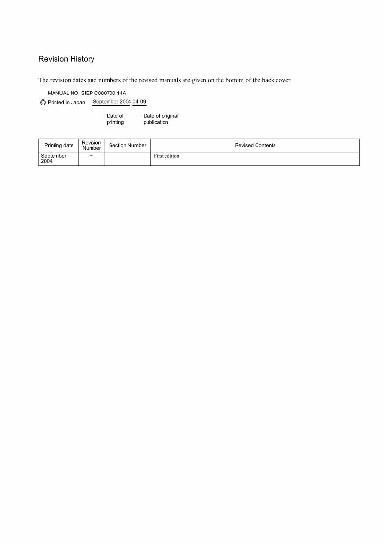
Revision History
The revision dates and numbers of the revised manuals are given on the bottom of the back cover.
Printing date Revision Number Section Number Revised Contents
September 2004
− First edition
C Printed in Japan
MANUAL NO. SIEP C880700 14A September 2004 04-09
Date of printing
Date of original publication
YASKAWA
YASKAWA ELECTRIC CORPORATION
Printed in Japan September 2004 04-9
MANUAL NO. SIEP C880700 14A
04-8⑥
IRUMA BUSINESS CENTER480, Kamifujisawa, Iruma, Saitama 358-8555, JapanPhone 81-4-2962-5696 Fax 81-4-2962-6138
YASKAWA ELECTRIC AMERICA, INC.2121 Norman Drive South, Waukegan, IL 60085, U.S.A.Phone 1-847-887-7000 Fax 1-847-887-7370
MOTOMAN INC. HEADQUARTERS805 Liberty Lane West Carrollton, OH 45449, U.S.A.Phone 1-937-847-6200 Fax 1-937-847-6277
YASKAWA ELETRICO DO BRASIL COMERCIO LTD.A.Avenida Fagundes Filho, 620 Bairro Saude-Sao Paulo-SP, Brazil CEP: 04304-000Phone 55-11-5071-2552 Fax 55-11-5581-8795
YASKAWA ELECTRIC EUROPE GmbHAm Kronberger Hang 2, 65824 Schwalbach, GermanyPhone 49-6196-569-300 Fax 49-6196-569-312
Motoman Robotics Europe ABBox 504 S38525 Torsas, SwedenPhone 46-486-48800 Fax 46-486-41410
Motoman Robotec GmbHKammerfeldstraβe 1, 85391 Allershausen, GermanyPhone 49-8166-90-100 Fax 49-8166-90-103
YASKAWA ELECTRIC UK LTD.1 Hunt Hill Orchardton Woods Cumbernauld, G68 9LF, United KingdomPhone 44-1236-735000 Fax 44-1236-458182
YASKAWA ELECTRIC KOREA CORPORATION7F, Doore Bldg. 24, Yeoido-dong, Youngdungpo-Ku, Seoul 150-877, KoreaPhone 82-2-784-7844 Fax 82-2-784-8495
YASKAWA ELECTRIC (SINGAPORE) PTE. LTD.151 Lorong Chuan, #04-01, New Tech Park Singapore 556741, SingaporePhone 65-6282-3003 Fax 65-6289-3003
YASKAWA ELECTRIC (SHANGHAI) CO., LTD.No.18 Xizang Zhong Road. Room 1805, Harbour Ring Plaza Shanghai 20000, ChinaPhone 86-21-5385-2200 Fax 86-21-5385-3299
YATEC ENGINEERING CORPORATION4F., No.49 Wu Kong 6 Rd, Wu-Ku Industrial Park, Taipei, TaiwanPhone 886-2-2298-3676 Fax 886-2-2298-3677
YASKAWA ELECTRIC (HK) COMPANY LIMITEDRm. 2909-10, Hong Kong Plaza, 186-191 Connaught Road West, Hong KongPhone 852-2803-2385 Fax 852-2547-5773
BEIJING OFFICERoom No. 301 Office Building of Beijing International Club, 21Jianguomenwai Avenue, Beijing 100020, ChinaPhone 86-10-6532-1850 Fax 86-10-6532-1851
TAIPEI OFFICE9F, 16, Nanking E. Rd., Sec. 3, Taipei, TaiwanPhone 886-2-2502-5003 Fax 886-2-2505-1280
SHANGHAI YASKAWA-TONGJI M & E CO., LTD.27 Hui He Road Shanghai China 200437Phone 86-21-6553-6060 Fax 86-21-5588-1190
BEIJING YASKAWA BEIKE AUTOMATION ENGINEERING CO., LTD.30 Xue Yuan Road, Haidian, Beijing P.R. China Post Code: 100083Phone 86-10-6233-2782 Fax 86-10-6232-1536
SHOUGANG MOTOMAN ROBOT CO., LTD.7, Yongchang-North Street, Beijing Economic Technological Investment & Development Area, Beijing 100076, P.R. ChinaPhone 86-10-6788-0551 Fax 86-10-6788-2878
In the event that the end user of this product is to be the military and said product is to be employed in any weapons systems or the manufacture thereof, the export will fall under the relevant regulations as stipulated in the Foreign Exchange and Foreign Trade Regulations. Therefore, be sure to follow all procedures and submit all relevant documentation according to any and all rules, regulations and laws that may apply.
Specifications are subject to change without notice for ongoing product modifications and improvements.
© 2004 YASKAWA ELECTRIC CORPORATION. All rights reserved.
Machine Controller MP2200USER'S MANUAL