Machinability Enhancement of non leaded free cutting ...
151
Machinability Enhancement of Non-Leaded Free Cutting Steels Von der Fakultät für Maschinenwesen der Rheinisch-Westfälischen Technischen Hochschule Aachen zur Erlangung des akademischen Grades eines Doktors der Ingenieurwissenschaften genehmigte Dissertation vorgelegt von Diplom-Ingenieur Ingo Essel aus Aachen Berichter: Univ.-Prof. Dr.-Ing. F. Klocke Prof. Dr.-Ing. G. Byrne Tag der mündlichen Prüfung: 22. Mai 2006 Diese Dissertation ist auf den Internetseiten der Hochschulbibliothek online verfügbar.
Transcript of Machinability Enhancement of non leaded free cutting ...

Machinability Enhancement ofNon-Leaded Free Cutting Steels
Von der Fakultät für Maschinenwesen der Rheinisch-Westfälischen Technischen Hochschule Aachen
zur Erlangung des akademischen Grades einesDoktors der Ingenieurwissenschaften
genehmigte Dissertation
vorgelegt von
Diplom-Ingenieur Ingo Essel
aus Aachen
Berichter: Univ.-Prof. Dr.-Ing. F. Klocke Prof. Dr.-Ing. G. Byrne
Tag der mündlichen Prüfung: 22. Mai 2006
Diese Dissertation ist auf den Internetseitender Hochschulbibliothek online verfügbar.


Band 17/2006Shaker Verlag
Herausgeber:Prof. em. Dr.-Ing. Dr. h. c. mult. Dipl.-Wirt. Ing. W. Eversheim
Prof. Dr.-Ing. F. KlockeProf. em. Dr.-Ing. Dr. h. c. mult. Prof. h. c. T. Pfeifer
Prof. Dr.-Ing. Dipl.-Wirt. Ing. G. SchuhProf. em. Dr.-Ing. Dr.-Ing. E. h. Dr.-Ing. E. h. M. Weck
Prof. Dr.-Ing. C. BrecherProf. Dr.-Ing. R. Schmitt
Berichte aus der Produktionstechnik
Ingo Essel
Machinability Enhancement ofNon-Leaded Free Cutting Steels

Bibliographic information published by Die Deutsche BibliothekDie Deutsche Bibliothek lists this publication in the DeutscheNationalbibliografie; detailed bibliographic data is available in the internet athttp://dnb.ddb.de.
Zugl.: Aachen, Techn. Hochsch., Diss., 2006
Copyright Shaker Verlag 2006All rights reserved. No part of this publication may be reproduced, stored in aretrieval system, or transmitted, in any form or by any means, electronic,mechanical, photocopying, recording or otherwise, without the prior permissionof the publishers.
Printed in Germany.
ISBN-10: 3-8322-5310-6ISBN-13: 978-3-8322-5310-3ISSN 0943-1756
Shaker Verlag GmbH • P.O. BOX 101818 • D-52018 AachenPhone: 0049/2407/9596-0 • Telefax: 0049/2407/9596-9Internet: www.shaker.de • e-mail: [email protected]

Vorwort
Die vorliegende Arbeit entstand neben meiner Tätigkeit als wissenschaftlicher Mitar-beiter am Laboratorium für Werkzeugmaschinen und Betriebslehre (WZL) der RWTH Aachen.
Prof. Dr.-Ing. F. Klocke, dem Inhaber des Lehrstuhls für Technologie der Fertigungs-verfahren, danke ich für die Ermöglichung und Betreuung der Arbeit. Ebenso bedanke ich mich bei Prof. Dr.-Ing. G. Byrne für die Übernahme des Korrefe-rats und seine Bereitschaft, dafür die Reise von Irland nach Aachen zu unternehmen. Herrn Prof. Dr.-Ing. U. Dilthey gilt mein Dank für die Übernahme des Prüfungsvorsit-zes.
Die Europäische Union hat im Rahmen eines EGKS-Projektes einen Teil der Arbei-ten gefördert. Der Europäischen Union und besonders allen beteiligten Firmen und deren Mitarbeitern gilt mein aufrichtiger Dank für ihre Unterstützung.
Für zahlreiche anregende Diskussionen und Ratschläge bedanke ich mich bei mei-nen derzeitigen und ehemaligen Kollegen, besonders bei Dipl.-Ing. P. Frank und Dr.-Ing. S. Hoppe sowie Dr.-Ing. Kai Risse für die kritische Durchsicht meines Manu-skriptes.
Mein Dank gilt ebenso meinen studentischen Mitarbeitern sowie Studienarbeitern und den Mitarbeitern der Dienstleistungsbereiche des WZL. Für das außerordentli-che Engagement in der Metallographie danke ich B. Niederbach und C. Hohlstein.
Meine Eltern haben das Fundament meiner Ausbildung gelegt und dadurch diese Arbeit ermöglicht. Ihnen spreche ich tiefe Dankbarkeit für Ihre Unterstützung aus.
Schließlich möchte ich ganz besonders meiner Frau Nicole für Ihre motivierende Un-terstützung, für die Schaffung der notwendigen Freiräume sowie für Ihre Geduld während der Erstellung der Arbeit danken.
Aachen, im Juli 2006

Table of Contents I
Table of Contents
TABLE OF CONTENTS .............................................................................................. I
SYMBOLS AND ABBREVIATIONS .......................................................................... III
1 INTRODUCTION ................................................................................................. 1
2 BASICS AND INITIATION INTO THE TOPIC ..................................................... 2
2.1 Evaluation Criteria for Machinability ............................................................ 2
2.2 Concept of Free Cutting Steel....................................................................... 3
2.3 Previous Work on Machinability of Free Cutting Steels............................. 4
2.4 Health Aspects of Lead................................................................................ 10
2.5 Legal Regulations ........................................................................................ 11
3 OBJECTIVE OF THE WORK............................................................................ 13
4 MATERIAL CHARACTERISATION................................................................... 15
4.1 Low Carbon Free Cutting Steels................................................................. 15
4.2 Carbon Steels ............................................................................................... 20
4.3 Case Carburising Steels .............................................................................. 22
5 MACHINABILITY OF LEADED LOW CARBON FREE CUTTING STEEL ....... 24
5.1 Properties, Characteristics and Functions of Lead in Cutting ................ 24
5.2 Cutting Parameters and Tools .................................................................... 26
5.3 Screening of 11SMnPb30 ............................................................................ 285.3.1 Process Forces ....................................................................................... 285.3.2 Surface Quality........................................................................................ 355.3.3 Chip Formation Process.......................................................................... 375.3.4 Chip Forms.............................................................................................. 39
5.4 Tool Wear Testing of 11SMnPb30............................................................... 41
6 MACHINABILITY OF DIFFERENT ALLOYED FREE CUTTING STEELS ....... 47
6.1 Description of Possible Substitutes for Lead ........................................... 476.1.1 Phosphorus ( S, P = 44°C)....................................................................... 47
6.1.2 Sulphur ( S, S = 118°C) ........................................................................... 48
6.1.3 Tellurium and Selenium ( S, Te = 450°C, S, Se = 217°C)......................... 48
6.1.4 Tin ( S, Sn = 232°C) ................................................................................. 48

II Table of Contents
6.1.5 Bismuth ( S, Bi = 271°C)........................................................................... 49
6.2 Screening Test .............................................................................................. 506.2.1 Process Forces........................................................................................ 506.2.2 Specific Cutting Forces............................................................................ 556.2.3 Surface Quality ........................................................................................ 576.2.4 Chip Formation Process .......................................................................... 606.2.5 Chip Forms .............................................................................................. 63
6.3 Tool Wear Test .............................................................................................. 67
6.4 Interim Result................................................................................................ 81
7 EXPLANATION OF RESULTS FROM MACHINABILITY TESTING................. 82
7.1 Procedures in the Different Deformation Zones........................................ 82
7.2 Influence of Feed .......................................................................................... 91
7.3 Influence of Tool Coating............................................................................. 92
7.4 Influence of Cutting Fluid Application........................................................ 95
8 FULFILMENT OF THE REQUIREMENTS REGARDING MACHINABILITY..... 98
8.1 Target System ............................................................................................... 98
8.2 Assessment of Performance ....................................................................... 99
8.3 Evaluation of the Benefit............................................................................ 100
9 TRANSFER OF RESULTS .............................................................................. 103
9.1 Auto Lathe Test........................................................................................... 103
9.2 Machinability Enhancement of Carbon Steels (C45)............................... 1089.2.1 Screening Test ...................................................................................... 1089.2.2 Tool Wear Test ...................................................................................... 110
9.3 Machinability Enhancement of Case Carburising Steels (16MnCr5) ..... 1139.3.1 Screening Test ...................................................................................... 1139.3.2 Tool Wear Test ...................................................................................... 115
10 ECONOMICAL ASSESSMENT ....................................................................... 118
11 SUMMARY AND OUTLOOK ........................................................................... 120
12 LITERATURE................................................................................................... 122
CURRICULUM VITAE............................................................................................. 137

Symbols and Abbreviations III
Symbols and Abbreviations
1 - mcFactor for the rise of the cutting force (in depend-ence of h)
A mm2 Cross section
A5 % Elongation at break
Al Aluminium
Al2O3 Aluminium oxide
ap mm Depth of cut
As Arsenic
b Heat permeation coefficient
b mm Width of cut
bch mm Chip width
Bi Bismuth
BUE Build up edge
BUL Build up layer
C Carbon
Ca Calcium
cp J/(kg*K) Specific heat coefficient
cp,ch J/(kg*K) Specific heat coefficient of chip material
cp,to J/(kg*K) Specific heat coefficient of tool material
Cr Chromium
Cu Copper
D mm Diameter
dQch/dt W Heat flow towards chip
dQto/dt W Heat flow towards tool

IV Symbols and Abbreviations
EDX Energy dispersive x-ray analysis
d /dt K/s Temperature rise
Eeff J Effective energy
f mm Feed
F N Force
F’c N/mm Cutting force related to width of cut b
Fc N Cutting force
Ff N Feed force
Fp N Thrust force
F n N Normal Force
F t N Tangential Force
gi Weighting factor
Gwgj Benefit
h mm Uncut chip thickness
hch mm Chip thickness
HfN Hafnium nitride
hmin mm Minimum uncut chip thickness
HV Vickers hardness
kc N/mm2 Specific cutting force
k Force ratio (of tangential and normal force)
KF EUR/apiece Manufacturing cost per work piece
KML EUR/h Machine and labour hourly rate
KWT EUR Tool costs
L mm Measuring length

Symbols and Abbreviations V
lc m Length of cut
m Batch size
Mn Manganese
MnS Manganese sulphide
Mo Molybdenum
N Nitrogen
n rpm Rotational speed
Ni Nickel
O Oxygen
pc N/mm2 Cutting pressure
P W Power
P Phosphor
Pb Lead
PDZ Primary deformation zone
PR W Friction power on the rake
Q mm3/s Material removal rate
Ra μm Arithmetic mean value of surface roughness
Rkin μm Kinematic roughness
Rm N/mm2 Tensile strength
rn μm Cutting edge radius
Rt μm Single roughness peak height
Rz μm Peak to valley height
r mm Nose radius
S Sulphur

VI Symbols and Abbreviations
s μm thickness
Sb Antimony
SDZ Secondary deformation zone
Se Selenium
SEM Scanning electron microscope
Si Silicon
Sn Tin
T min Tool life time
tc min Cutting time
TDZ Tertiary deformation zone
Te Tellurium
th min Productive time
Ti(C,N) Titanium carbon nitride
TiN Titanium nitride
tn min Non-productive time
tr min Set-up time
tW min Tool change time
VBB μm Width of wear land at major cutting edge
VBC μm Width of wear land at cutting edge corner
VBmax μm Maximum width of wear land
VBNS μm Width of wear land at minor cutting edge
wij Degree of performance
wgij Single benefit
vc m/min Cutting speed

Symbols and Abbreviations VII
vch m/min Chip velocity
Z % Reduction of area
Z μm Distance of the surface profile to the average line
° Clearance angle
° Rake angle
r ° Lead angle
W/mK Thermal conductivity
nm Wave length
ch Chip compression
ch W/mK Thermal conductivity of chip material
° Inclination angle
to W/mK Thermal conductivity of tool material
Coefficient of friction
kg/cm3 Density
ch kg/cm3 Density of chip material
to kg/cm3 Density of tool material
N/mm2 Normal stress
max N/mm2 Maximum normal stress
N/mm2 Shear stress
s N/mm2 Shear flow stress
°C Temperature
s °C Melting temperature


1 Introduction 1
1 Introduction
In modern industrial society, steel is the basic material for sustainable development because of its versatile properties and its recycling possibilities. Steel finds applica-tion in nearly all important industrial sectors such as apparatus and machinery manu-facture, building industry, power and environmental engineering, transportation and packaging industry. In recent years world steel demand has accumulated steadily since 1999, whereas an acceleration of increase could be observed since 2002. World steel consumption rose by about 5 – 6.5 % a year and amounted to 1,129 mil-lion tons in 2005. Mainly, the strong surge in steel consumption has been driven by the strong demand in China, which has increased by about 25 % a year since 2001. Concerning world crude steel production Germany ranks in sixth place with an an-nual output of 44.7 million tons in 2005. Since 2002 the top position has been hold by China [STAH06, OECD04].
Leaded steels are only a small fragment in the overall steel consumption, but they play a significant role for manufacturing of mass parts such as screws, nuts, spark plugs or fittings by cutting processes [ENIR06]. For a long time leaded free cutting steels have been classified as first choice for machining operations due to their en-hanced machinability. However, in the recent years generally the use of lead has been under threat for environmental reasons. The most common sanction was probably the ban of lead in petrol at the end of the eighties. Today, legal regulations such as the directives on “Restriction of Certain Hazardous Substances (RoHS)” [2002/95] and on “Waste Electrical and Electronic Equipment (WEEE)” [2003/108] affect the use of lead in production of electrical and electronic equipment. Another example is the “Water Framework Directive (WFD)” [2000/60], which makes great demands on the manufacture of fittings mainly made from copper based alloys. The most important legal regulation for the presented work is the EU-directive on “End-of-Life Vehicles (ELV)”, which expressly envisages among others the minimisation of lead as alloying element in aluminium, copper and steel alloys.
In all application areas the minimisation or even the avoidance of lead is a great chal-lenge. In the electronic industry certainly the changeover to lead free soldering metal is the biggest problem. Concerning copper alloys and steels, the biggest challenge is the enhancement of machinability without adding lead. This is certainly a continuous process to which the present work should give a contribution.
The machinability of different alloyed non-leaded steels is going to be analysed and compared to standard leaded steel. Thereby, low carbon free cutting steels of the 11SMn30 type are going to be in focus.

2 2 Basics and Initiation into the Topic
2 Basics and Initiation into the Topic
2.1 Evaluation Criteria for Machinability
Machinability is a term for the totality of material properties, which influence the ma-chining process. It is a general description of the difficulties occurring during cutting a work piece material [KOEN02, NNA].
Generally, for the description of machinability the four main evaluation criteria proc-ess forces, surface quality, chip form and tool life are used [BICK63, KOEN02,TÖNS78]. Depending on the specific machining task the importance of every single criterion can vary. Nevertheless, in some cases these four criteria may not describe the machinability of a work piece material sufficiently and therefore other criteria like friction coefficient, cutting temperatures, layer formation, rim zone properties or build up edge formation have to be taken into account. However, these criteria are closely linked to the four main evaluation criteria and therefore they should not be consid-ered as separate machinability measures. TÖNSHOFF specified environmental as-pects as a further evaluation criterion [TÖNS98].
Low carbon free cutting steels are mainly applied for serious or mass production parts for instance in the automobile industry, for the production of small components for kitchen machines or for the manufacture of screws, nuts and several kinds of fit-tings [ENIR06]. Often the material is being machined on auto lathes, on multi spindle machines or on specific application oriented machine tools. The number of parts manufactured with one set of tools is quite high [BERS71, DREß64, SUTT84]. However, it has to be taken into account that a variety of machining processes such as turning, grooving, drilling, tapping and parting come into operation. Accordingly, the material has to assure good machinability at a broad range of cutting parameters. Automated production is important as cycle times are usually only a few seconds and the ma-chine tools run all over the week. Operators care for several machine tools and do not handle only one lathe.
Consequently, special demands are made on the machinability of low carbon free cutting steels. It is obvious that tool life is a main criterion for machinability but at least the same importance arises for the chip form. Good chip breakage is a prereq-uisite for man less production and automation of the parts manufacture. Particularly, for processes like turning or drilling chip breakage is an important task, in turning es-pecially when shaping tools are used and the chip formation cannot be influenced by chip breaking elements in the tool. In drilling often deep holes make great demands on chip breakage of the material. Considering the remaining two main evaluation cri-teria for machinability it may be mentioned that both process forces and surface qual-ity are important for machining of free cutting steel. Usually the process forces are comparably low but when special tools and machines with low rigidity are applied

2 Basics and Initiation into the Topic 3
even low forces may impair the stability of the cutting process and consequently the component quality. Beneath the dimensional quality, also the surface quality is impor-tant as the parts are usually finished by machining with geometric defined cutting edge and do not need finishing operations like grinding or polishing.
In addition to the main machinability evaluation criteria tool life, chip form, cutting forces and surface quality, some phenomena influencing these evaluation criteria have to be considered exceptionally. Since machining of free cutting steels is often performed on multi spindle machines and auto lathes, the applicable rotational speeds are low. In combination with small work piece diameters this results in low cutting speeds. Subsequently, the formation of build up edges (BUE) may have strong impact on tool life and surface quality. Further, the cutting temperatures have to be considered as chip formation, tool life, cutting force and dimensional quality depend on cutting temperatures. Temperatures on the rake of the tool also may give information about the tribological conditions in the contact zones of tool and work piece. Another important phenomenon is the layer formation. Build up layers from various chemical compositions on flank and rake faces of cutting tools may result in a reduction of cutting forces and temperatures and consequently reduce tool wear [KLOC98, KRIE00, SUBR03, ZINK99]. Figure 2.1 summarises the different criteria for evaluating the machinability of low carbon free cutting steels.
Tool life
Process forcesSurface quality
Chip forms
Build up edgesCutting temperatures
Build up layersTool life
Process forcesSurface quality
Chip forms
Build up edgesCutting temperatures
Build up layers
Figure 2.1: Evaluation criteria for machinability of low carbon free cutting steels
2.2 Concept of Free Cutting Steel
The manufacture of mass products makes great demands on automation of manu-facturing processes in order to decrease cycle times and thus manufacturing costs. As a result, reliable and efficient cutting processes are essential. The machinability of materials plays a significant role as usually 42 – 67 % of the total manufacturing costs originate from cutting processes [HUCH93]. Consequently, work piece materials are necessary, which allow for the exploitation of the technological limits given by machine tools, manufacturing processes as well as cutting tools and materials. The

4 2 Basics and Initiation into the Topic
arising material requirements can be summarised as follows [BERS71, DREß64,SUTT84]:
Tool wear as low as possible at cutting times as long as possible.
Short, lightly breaking chips to ensure undisturbed chip removal.
Sufficient surface quality.
Low cutting forces and temperatures to allow for the application of sensitive cutting tools and machines.
Since the work material properties are primarily determined by the purpose of use, the possibilities regarding modification of grain boundaries, slag content, cold work-ing or chemical composition are limited [BERS71]. The best approach to meet the mentioned requirements is represented by the big group of free cutting steels. The desired material properties with respect to machining processes are mainly obtained by alloying with sulphur and lead and further by adding other elements like phospho-rus, selenium, tellurium, antimony, calcium, bismuth or tin [BERN01, BERS71, DAHL93,DREß64, GARC02, KOEN02, TOEN95, VDEH84, VIER70]. Since machinability enhance-ment is not only important for mild steels, free cutting steels can be classified re-specting their heat treatment [DAHL93, EN10277, VDEH84]:
Low carbon free cutting steels (mild steels), which are not subject to heat treatment after machining (e.g. 11SMn30, 11SMnPb30, 11SMnPbTe30).
Free cutting case carburising steels with a low carbon and partially low sulphur content. As the name implies, these steels are used for case hardening after machining (e.g. 10S20, C15Pb, 16MnCrPb5, 16MnCrS5Pb).
Free cutting carbon (quench and tempering) steels characterised by carbon contents exceeding 0.3 %. Most steels of this group exhibit low sulphur con-tents in order to avoid substantial impact on material strength and toughness (e.g. 35S20, C35Pb, C45Pb).
2.3 Previous Work on Machinability of Free Cutting Steels
The machinability of free cutting steels was a big issue of the 20th century. Thereby, it was shown that the most important elements with respect to machinability enhance-ment were sulphur (mainly in combination with manganese) and lead. Accordingly, the research focus lay on investigations to describe the influencing factors on the cutting performance of resulphurised low carbon free cutting steels [APPL89, BERS71,DREß64, FROE75, GRAH33, HENT91, JIAN96, KISHI76, KREK51, MERC50, NAYL76,PAUD54, PAUD54A , RUEB11, SHAW61, SPEN62, VIER70, RAMA77, ZINK99].
In 1897 it was discovered that sulphur is able to improve machinability and therefore since 1903 low carbon free cutting steel with sulphur additions has been produced [GRAH33]. Admittedly, sulphur is only slightly soluble in steel and therefore the addi-

2 Basics and Initiation into the Topic 5
tion of only small amounts results in the formation of iron sulphide FeS, which has a melting point of only S, FeS = 988°C. When cooling down melted steel, FeS settles at the solidified crystals [VIER70]. When heating steel, the grain boundaries weaken in a temperature range from 800 to 1000°C and lead to red brittleness, which implicates possibly failure in warm forming processes. At temperatures exceeding 1200°C FeS liquefies and causes hot breakage [DAHL93]. In order to prevent this impairing effect, manganese is also added in the steel making process. It has a stronger affinity to sulphur and therefore builds manganese sulphide MnS, which is characterised by a high melting temperature of S, MnS = 1520°C. The sulphides solidify prior to the re-maining melt as round inclusions, which act as seed crystals [DREß64, VIER70].The manganese content should amount 4 – 5 times of the sulphur content (Mn = 2.5*S + 0.15) to avoid the formation of FeS [DAHL93, KOEN02]. Usual sulphur contents lie between 0.1 and 0.4 % and should not be higher as MnS deteriorates warm rollability. The influence on tensile strength and micro structure is irrelevant, but the marked anisotropy impairs toughness in transverse direction [VDEH84].
The shape of sulphide inclusions is basically defined by the oxygen content dissolved in the steel during solidification [FROE75]. Three different types of inclusions are told apart [APPL89, FROE75, KOEN02]:
Type 1 inclusions form as liquid phase in iron rich melts containing oxygen contents greater than 0.2 % according to the system Fe-MnO-MnS. Typical examples are rimmed or semi-killed steels with very low content of Al and Si. After solidification these sulphides are randomly dispersed and show a globu-lar or irregularly rounded shape. The inclusions are brittle and exist individually in closed segments. As a result of the high oxygen content, these sulphides show low deformability, which makes decisive impact on machinability.
Type 2 sulphides can be found in melts containing oxygen contents lower than 0.1 %. This type is usually present in killed steel. It segregates in an eutectic like MnS-phase. Type 2 inclusions are not to be found in closed segments but rather as fine sulphides in a fan or chain like pattern, actually precipitated as interconnected branched rods.
Type 3 originates at very low oxygen contents in iron melts with low melting point. These sulphides only occur when excessive amounts of deoxidisers are present. They are randomly dispersed and show angular or faceted shapes.
The size and spacing of each of these morphological types can vary, depending on the solidification rate [MARS70]. When the cast steel is subsequently hot worked, Type 1 sulphides tend to deform less than the matrix does and thus assume a somewhat elliptical shape. Type 2 sulphides, already fine and with elongated mor-phology, deform due to hot working and form clusters of long, thin particles along the principal deformation direction [APPL89].

6 2 Basics and Initiation into the Topic
Main effects of MnS in cutting result in a reduction of process forces, cutting tem-perature and chip thickness and the presence of MnS causes a movement of the cutting speed range where build up edges occur towards higher cutting speeds. However, regarding the function of MnS during cutting, partly oppositional explana-tions exist:
1. Reduction of the friction coefficient in the contact zones due to MnS layer forma-tion [APPL89, MERC50, VIER70, ZINK99]. In contrast, SHAW ET AL. reported as a re-sult of friction tests that MnS shows poor lubrication properties [SHAW61].
2. Reduction of friction due to the crystalline structure of the MnS metalloid. In the lattice the sulphur atoms are located in a hexagonal plane, which are likely to slide over each other [DREß64, PAUD54, PAUD54A].
3. In the shear zone MnS operates as stress raiser. The sulphides can be regarded as voids, which lead to embrittlement of the material and support the initiation of micro cracks within the primary deformation zone (PDZ). Subsequently, flow stress is reduced [JIAN96, KISHI76].
4. Reduction of tool wear since MnS performs as a diffusion barrier [JIAN96, QI00].
5. Decrease of inner friction and reduction of flow stress of the work piece material. Correspondingly, reduction of friction in the contact zones due to lower normal forces [APPL89, VIER70].
The friction reducing effects of MnS are of vital importance and can be specified ac-cording to APPLE [APPL89] as follows. Under most machining conditions the contact zone between chip and tool rake can be distinguished into two regions. The region close to the tool tip is characterised by seizure and the rear part of the contact zone is dominated by sliding. Figure 2.2 illustrates these areas and further shows the dis-tribution of normal compressive stress ( ) and tangential shear stress ( ) acting on the rake of the tool. The normal stress decreases from its maximum max to zero from the tool tip to that point where the chip leaves the rake (A – C). A lot of researchers investigated the exact distribution of normal and tangential forces on the cutting tool [AHMA89, CHIL89, GORD67, KATO72, KATT57, LUTZ68, PRIM69, SPAA67, USUI60,ZIEB95] but a very simple distribution as proposed in Figure 2.2 is sufficient for the explanation of effects due to MnS inclusions.

2 Basics and Initiation into the Topic 7
Stre
ss
max
s
Distance x
Normal stress Tangential shear stress
Seizedregion
Slidingregion
Total contact length
Chip
Workpiece
vc F ~ dx
Tool
Chip
Tool
Work piece vc
PDZ SDZ PDZ SDZ
BUE
PDZ: Primary deformation zone
SDZ: Secondary deformation zone
BUE: Build up edge
A B C
Stre
ss
max
s
Distance x
Normal stress Tangential shear stress
Seizedregion
Slidingregion
Total contact length
Chip
Workpiece
vc F ~ dx
Tool
Chip
Tool
Work piece vc
PDZ SDZ PDZ SDZ
BUE
PDZ SDZ PDZ SDZ
BUE
PDZ: Primary deformation zone
SDZ: Secondary deformation zone
BUE: Build up edge
A B C
Figure 2.2: Distribution of normal and tangential stresses in the tool-chip con-tact region [APPL89]
The shear stress can be calculated in the sliding region (B – C) by means of the normal stress and the friction coefficient with
(sliding) Equation 2.1
and in the seized area (A – B) by
s (seizure) Equation 2.2
where s is the flow stress of the chip material, which is reached in the secondary deformation zone (SDZ) at the bottom of the chip [APPL89, SHAW60, SHAW63].Hence, becomes independent of normal stress [APPL89, THOM63], feed [BOWD54,MEYE63, SHAW56, THOM62, WITT80], depth of cut and rake angle [TAKE64]. Accord-ingly, for the seized region a maximum friction coefficient max can be calculated by means of the shear flow stress according to von Mises [ZINK99]:
3s Equation 2.3
577.03
1smax Equation 2.4
The total tangential force parallel to the rake is proportional to the area under the -x-curve (Figure 2.2). Thus, the cutting process can be improved if or respectively the seized region is being reduced. On the one hand this is realised by MnS inclusion effects (reduction of flow stress) in the primary deformation zone [JIAN96, KISHI76],which results in lower normal stresses and due to the mentioned correlation with the friction coefficient in a reduction of . On the other hand, the tangential force can also

8 2 Basics and Initiation into the Topic
be affected directly through the actions of MnS inclusions near the tool-chip interface. The reduction of the friction coefficient reduces in the sliding region and it causes also a decrease of the seized area, which finally results in a decrease of the tangen-tial force [APPL89]. Further, MnS inclusions may become highly elongated parallel to the rake in the secondary deformation zone and may form surfaces of weakness [APPL89, TREN65]. Hence, they could reduce flow stress in the secondary deformation zone, which again contributes to a reduction of the tangential force.
To achieve the mentioned effects of MnS inclusions during machining, different re-searches placed emphasis on the influence of shape, distribution, dimension and deformability of non metallic inclusions on machining performance [APPL89, AREN04,DREß64, FROE75, GRAH33, HENT91, JIAN96, RAMA77, RAMU96, VIER70]. It was pointed out, that globular sulphide inclusions of type 1 showing low deformation ability have a positive impact on the cutting process. If a sulphide inclusion was deformed as much as the steel matrix containing it, plastic flow in the material would be homogenous and undisturbed. The role of MnS inclusions as a stress concentration inducer would then be minimal. Further, possible shear concentration effects at the interface be-tween non-deforming inclusions and a ductile matrix would be absent [RAMA77]. Re-cent investigations of Arendt [AREN04] show, that the decisive influencing factor re-garding machinability enhancement is the amount of sulphide inclusions per volume rather than the size of the inclusions. Further, Arendt exposed that machinability en-hancement due to long stretched sulphide inclusions of type 2 is also possible.
DREßLER [DREß64] investigated in detail the influence of different work piece areas, the steel production process, sulphur and lead additions as well as cutting fluid. Fur-ther this work contained the evaluation of different machinability testing methods in order to show which short term tests are profitable for machinability testing. However, it was shown that the most important measure for improving machinability was the addition of lead. Main benefits from adding lead can be summarised as follows [APPL89, BAKE68, BECK77, BENE61, BERN01, BERS71, CLIN88, FINN90, GARC98,KAEM69, KLAU65, KOEN02, LEWI58, RAMU96, ROLL65, SCHR43, SHAW61, SOME01,TOEN95, TREN65, TROU33, VIER70, WIES61, ZLAT59]:
Reduction of tool wear as a result of decreasing friction, lower cutting tem-peratures, and a diminution of cutting forces.
Movement of undesirable build up edge formation towards higher cutting speeds and concurrently decrease and stabilisation of build up edges resulting in enhanced machining performance at low speeds.
Generation of strongly curved, short breaking chips.
Enhanced surface quality particularly at low cutting speeds.
Generally, in steels lead contents up to 0.35 % are believed to improve machinability, whereas the dependency of the wear behaviour of leaded steel should be analysed more detailed. Lead and sulphur content are decisive as the degree of improvement

2 Basics and Initiation into the Topic 9
due to lead diminishes with increasing sulphur content [BAKE68, SCHR43]. Increasing lead content results in a strong improvement at low cutting speeds, whereas at higher speeds a deterioration of the cutting performance is probable [BERS71]. How-ever, the influence of lead additions on tool wear has to be distinguished regarding the wear form. DREßLER [DRES64] showed that due to alloying with lead (9SMnPb23) flank wear could be reduced by about 40 %, whereas crater wear increased by about 33 %. These higher values for crater wear could be justified with rising surface pres-sure. Since the cutting force decreased not as much as the length of the contact zone, the surface pressure was presumed to rise, which resulted in stronger crater wear. The increases wear attack on the rake due to alloying with lead was confirmed in extensive machinability tests by BERSCH [BERS71]. In turning at the whole cutting speed range of vc = 80 – 140 m/min, 9SMnPb28 caused stronger crater wear com-pared to lead free 9SMn28 and a significant influence of cutting speed was not visi-ble.
Contrary, when analysing flank wear it could be realised that the major influencing factor on the wear behaviour of leaded steel is the cutting speed. The drop of tool wear with increasing cutting speed was larger for leaded steel and correspondingly the Taylor straight lines of 9SMnPb28 and 9SMn28 intersected at a cutting speed of about 100 m/min. This implicates, that tool life in cutting leaded 9SMnPb28 was higher at low cutting speeds, whereas at increased cutting speeds more tool wear occurred compared to 9SMn28. This correlation was not depending on the applica-tion of cutting fluid. The main reason for the reduction of flank wear at cutting speeds below 100 m/min can be seen in the formation of build up edges. Leaded steels show significantly smaller dimensions of build up edges and the frequencies characterising the release of build up edges from the tool are lower. In contrast the temperature re-ducing effect of lead results in build up edge formation at cutting speeds, where in machining non-leaded steels build up edges no longer occur [BERS71, KLAU65,SHAW61, TREN65, ZLAT59].
More recent investigations of Arendt [AREN04] on free cutting case carburising steels (16MnCr5Pb and 16MnCr5S) confirmed the results. Using uncoated carbide inserts in a dry cut, an increase in machined material volume could be achieved for the leaded steel at vc = 200 m/min, whereas at vc = 340 m/min a reduction by 12 % was ascertained. Similar results could be obtained in turning with coated carbide tools.
Most investigations regarding the performance of lead were focussed on turning ex-periments but it was also reported on improved machining performance in drilling processes [GREE02]. These tests confirmed the machinability enhancing behaviour of lead as the torque was reduced and the maximum number of bore holes until tool failure could be increased.
The cognition that alloying with lead is the best way to enhance machinability was gained a long time ago, whereas newer investigations dealt with possible alternatives to lead as machinability enhancer. However, this research was mainly focussed on
10 2 Basics and Initiation into the Topic
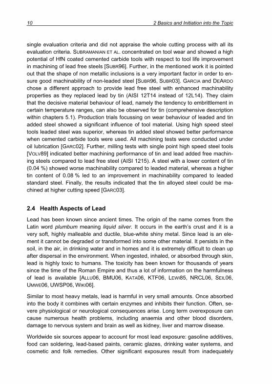
single evaluation criteria and did not appraise the whole cutting process with all its evaluation criteria. SUBRAMANIAN ET AL. concentrated on tool wear and showed a high potential of HfN coated cemented carbide tools with respect to tool life improvement in machining of lead free steels [SUBR96]. Further, in the mentioned work it is pointed out that the shape of non metallic inclusions is a very important factor in order to en-sure good machinability of non-leaded steel [SUBR96, SUBR03]. GARCIA and DEARDO
chose a different approach to provide lead free steel with enhanced machinability properties as they replaced lead by tin (AISI 12T14 instead of 12L14). They claim that the decisive material behaviour of lead, namely the tendency to embrittlement in certain temperature ranges, can also be observed for tin (comprehensive description within chapters 5.1). Production trials focussing on wear behaviour of leaded and tin added steel showed a significant influence of tool material. Using high speed steel tools leaded steel was superior, whereas tin added steel showed better performance when cemented carbide tools were used. All machining tests were conducted under oil lubrication [GARC02]. Further, milling tests with single point high speed steel tools [VOLV89] indicated better machining performance of tin and lead added free machin-ing steels compared to lead free steel (AISI 1215). A steel with a lower content of tin (0.04 %) showed worse machinability compared to leaded material, whereas a higher tin content of 0.08 % led to an improvement in machinability compared to leaded standard steel. Finally, the results indicated that the tin alloyed steel could be ma-chined at higher cutting speed [GARC03].
2.4 Health Aspects of Lead
Lead has been known since ancient times. The origin of the name comes from the Latin word plumbum meaning liquid silver. It occurs in the earth’s crust and it is a very soft, highly malleable and ductile, blue-white shiny metal. Since lead is an ele-ment it cannot be degraded or transformed into some other material. It persists in the soil, in the air, in drinking water and in homes and it is extremely difficult to clean up after dispersal in the environment. When ingested, inhaled, or absorbed through skin, lead is highly toxic to humans. The toxicity has been known for thousands of years since the time of the Roman Empire and thus a lot of information on the harmfulness of lead is available [ALLU06, BMU06, KATA06, KTF06, LEWI85, NRCL06, SEIL06,UMWE06, UWSP06, WIKI06].
Similar to most heavy metals, lead is harmful in very small amounts. Once absorbed into the body it combines with certain enzymes and inhibits their function. Often, se-vere physiological or neurological consequences arise. Long term overexposure can cause numerous health problems, including anaemia and other blood disorders, damage to nervous system and brain as well as kidney, liver and marrow disease.
Worldwide six sources appear to account for most lead exposure: gasoline additives, food can soldering, lead-based paints, ceramic glazes, drinking water systems, and cosmetic and folk remedies. Other significant exposures result from inadequately

2 Basics and Initiation into the Topic 11
controlled industrial emissions from such operations as lead smelters and battery recycling plants, which contaminate environment and people in the surrounding ar-eas. The highest level of environmental contamination is found to be associated with uncontrolled recycling operations [NRCL06].
However, in metal cutting of steels with up to 0.35 % lead, the harmful effect of lead is believed to be low [UKST98]. Nevertheless in steel processing, in metal cutting and finally in recycling processes dust and fume containing lead are generated. Investiga-tions conducted by ARENDT [AREN04] revealed a strong exceeding of the permitted MAK-values (maximum allowable concentration at the workplace) in dry cutting of leaded steels using high cutting speeds. Thus, the use of lead as machinability en-hancer has to be put into question.
2.5 Legal Regulations
Recycling of steel scrap is closely connected with environmental protection since steel scrap is a marvellous secondary raw material. In contrast to all other secondary raw materials, the reuse of metal scrap is unlimited without loss in quality. Scrap-based steel production saves about 86 % CO2 compared to the use of ore, which currently means for Germany a reduction of CO2 by 27 t a year. For each ton of scrap, which is used instead of pig iron, 1.5 t ore need not to be mined and 0.5 t combustibles need not to be conveyed and transported over wide distances. Overall, the energy reduction as a result of using secondary raw material is about 90 % [BDSV01].
In Germany about 3.5 million cars a year are put out of operation and sent for scrap-ping or recycling. Therefore, since April 1998 the disposal of old cars has already been regulated nationally by the “End-of-Life Vehicles Ordinance”. Nationwide, a re-turn network consisting of about 15,000 reception points, over 1,000 recycling busi-nesses and 65 shredder plants were build [BMU05]. The ordinance from 1998 was replaced by an act on the disposal of end-of-life vehicles in July 2002 [ALTF02], which was the national implementation of the directive on end-of-life vehicles 2000/53/EC constituted by the European Parliament and the Council in September 2000 [2000/53]. This directive forms the statutory framework of vehicle disposal in Europe [BMU05]. It establishes certain minimum targets with respect to the quantitative re-use, recycling and recovery rates for all end-of-life vehicles [SAND00].
However, the directive 2000/53/EC does not only provide rules regarding the recov-ery of end-of-life cars but it also intervenes in the design of new vehicles referring to environmental reasons [2000/53, VDA05]. The directive prohibits bringing on market vehicles and components containing the heavy metals cadmium, mercury, hexava-lent chromium and lead. Beside the use of lead and lead components for instance in batteries, fuel tanks, vibration dampers, electrical components or for soldering, the application of lead as an alloying element is also under threat. Copper and aluminium

12 2 Basics and Initiation into the Topic
alloys as well as zinc coatings and certainly steels are supposed to be used without any lead addition. In the particular case of steel, this affects for instance the produc-tion of crank shafts, connection rods, fitting turn-offs or high pressure fuel injector parts. Since around 50 % of the value of a machined automobile component is due to the machining cost, the prohibition of lead is very important regarding a probable de-terioration of machinability [SAND00].
However, since such a general ban is technically not achievable annex II of directive 2000/53/EC defines exceptions, which include among other things the permission of lead additions up to 0.35 % in steels. Although this permission is not limited in time, periodical reviews should show the possibility of an unexceptional prohibition of lead [2000/53, VDA05].
3 Objective of the Work 13
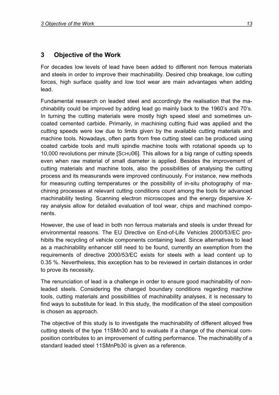
3 Objective of the Work
For decades low levels of lead have been added to different non ferrous materials and steels in order to improve their machinability. Desired chip breakage, low cutting forces, high surface quality and low tool wear are main advantages when adding lead.
Fundamental research on leaded steel and accordingly the realisation that the ma-chinability could be improved by adding lead go mainly back to the 1960’s and 70’s. In turning the cutting materials were mostly high speed steel and sometimes un-coated cemented carbide. Primarily, in machining cutting fluid was applied and the cutting speeds were low due to limits given by the available cutting materials and machine tools. Nowadays, often parts from free cutting steel can be produced using coated carbide tools and multi spindle machine tools with rotational speeds up to 10,000 revolutions per minute [SCHU06]. This allows for a big range of cutting speeds even when raw material of small diameter is applied. Besides the improvement of cutting materials and machine tools, also the possibilities of analysing the cutting process and its measurands were improved continuously. For instance, new methods for measuring cutting temperatures or the possibility of in-situ photography of ma-chining processes at relevant cutting conditions count among the tools for advanced machinability testing. Scanning electron microscopes and the energy dispersive X-ray analysis allow for detailed evaluation of tool wear, chips and machined compo-nents.
However, the use of lead in both non ferrous materials and steels is under thread for environmental reasons. The EU Directive on End-of-Life Vehicles 2000/53/EC pro-hibits the recycling of vehicle components containing lead. Since alternatives to lead as a machinability enhancer still need to be found, currently an exemption from the requirements of directive 2000/53/EC exists for steels with a lead content up to 0.35 %. Nevertheless, this exception has to be reviewed in certain distances in order to prove its necessity.
The renunciation of lead is a challenge in order to ensure good machinability of non-leaded steels. Considering the changed boundary conditions regarding machine tools, cutting materials and possibilities of machinability analyses, it is necessary to find ways to substitute for lead. In this study, the modification of the steel composition is chosen as approach.
The objective of this study is to investigate the machinability of different alloyed free cutting steels of the type 11SMn30 and to evaluate if a change of the chemical com-position contributes to an improvement of cutting performance. The machinability of a standard leaded steel 11SMnPb30 is given as a reference.

14 3 Objective of the Work
Based on the requirements on the machinability of free cutting steels, evaluation cri-teria are chosen. According to these evaluation criteria, the machinability of a leaded free cutting steel 11SMnPb30 is described. Considering the effect of lead on ma-chinability, alternative alloying elements are chosen and modified steel compositions predefined. Thereby, the environmental meaning of the different alloying elements is taken into account.
A comprehensive analysis of chemical composition and mechanical technological properties as well as an extensive metallographic characterisation describe in depth the different alloyed steels.
The evaluation of machinability of the different materials with regard to the prelimi-nary defined evaluation criteria is part of an extensive machinability test. Thereby, the main emphasis is put on dry turning experiments using uncoated and coated ce-mented carbide tools. For the judgement, in which way the requirements of ma-chinability can be respected by the different materials, a benefit analysis is carried out. It allows for a transparent demonstration of the potential regarding lead substitu-tion. Once machinability testing of the different free cutting steels is completed, the possibility of transferring the results to other processes (auto lathe test) and other steel groups (carbon steels or case carburising steels) is scrutinised. Finally, a short economical assessment gives a hint if the possibilities of machinability improvement shown within this study are both technologically and also commercially viable.
The strategy of this work is summarised schematically in Figure 3.1.
Machinability of leaded steel
Properties, characteristics,
functionsof lead
Possiblesubstitutes
for lead
Machiningtests
(11SMn30 type)
Explanationof results
Transfer of results
Benefitanalysis
Economicalassessment
Machinability of leaded steel
Properties, characteristics,
functionsof lead
Possiblesubstitutes
for lead
Machiningtests
(11SMn30 type)
Explanationof results
Transfer of results
Benefitanalysis
Economicalassessment
Figure 3.1: Strategy for analysing the machining performance of different al-loyed steels
The results of this study give information, which alloying elements contribute to an improvement of machinability and they identify which materials shall be subject of further investigations. It represents an important step toward a renunciation of lead in steels according to the EU Directive on End-of-Life Vehicles.

4 Material Characterisation 15
4 Material Characterisation
Focus of the work is the investigation of machinability of different alloyed steels to gain information regarding the influence of different alloying elements against the background of lead replacement. Therefore, a comprehensive material characterisa-tion regarding chemical composition, microstructure, non-metallic inclusions and me-chanical technological properties is necessary. The investigated materials were pro-vided by the companies Saarstahl (D), Corus (UK), Ascometal (F), Sidenor (E) and the Institute for Ferrous Metallurgy of RWTH Aachen (IEHK). Material characterisa-tion was deducted at the material suppliers as well as at the Laboratory for Machine Tools and Production Engineering (WZL) at RWTH Aachen.
4.1 Low Carbon Free Cutting Steels
Six different low carbon free cutting steels of the basic type 11SMn30 were used for the cutting experiments. The chemical composition is given in Table 4.1.
Material C Si Mn P S Cr Mo Ni Al Cu Sn Pb Bi 11SMn37 0.080 0.012 1.22 0.076 0.37 0.07 0.005 0.02 0.001 0.06 0.007 11SMn30+Sn 0.087 0.010 1.06 0.055 0.30 0.04 0.003 0.02 0.001 0.01 0.055 11SMn30+Sn+Cu 0.086 0.011 1.09 0.053 0.31 0.04 0.003 0.02 0.001 0.19 0.056 11SMnPb30 0.080 0.004 1.09 0.058 0.32 0.03 0.004 0.03 <0.005 0.01 0.002 0.3 11SMn30 0.080 0.005 1.02 0.058 0.31 0.01 0.002 0.02 <0.005 0.01 0.002 11SMn30+Bi 0.090 0.003 1.06 0.056 0.29 0.01 0.002 0.01 0.002 0.01 0.001 0.075
Table 4.1: Chemical composition of low carbon free cutting steels (%)
The materials were delivered in rolled condition of diameter D = 80 mm and in a cold drawn state of diameter D = 19 mm. Prior to drawing, the 20.8 mm bars of the two tin added materials were given an annealing treatment at 500°C for two hours. This treatment is designed to promote settling of tin at the grain boundaries [DEAR99A].
The microstructure of the six round 19 mm materials is plotted in Figure 4.1, the mi-crographs from the material of diameter D = 80 mm are given in Figure 4.2. The non-etched longitudinal sections show size and distribution of the non-metallic inclusions, the etched samples display the microstructure. As expected the microstructure con-tained 5 – 10 % pearlite and as balance ferrite (Table 4.2). Typically, for both material dimensions the orientation of the microstructure is visible comparing the longitudinal and cross sections. The grain size of the smaller bars is generally finer compared to the 80 mm material due to higher strain. Further, the pearlite content of the 19 mm material was slightly lower.

16 4 Material Characterisation
11SMn37
11SMn30+Sn
11SMn30+Sn+Cu
11SMn30
11SMnPb30
11SMn30+Bi
250 μm
Longitudinal sectionnon-etched
Longitudinal sectionetched
Cross sectionetched
11SMn37
11SMn30+Sn
11SMn30+Sn+Cu
11SMn30
11SMnPb30
11SMn30+Bi
250 μm250 μm
Longitudinal sectionnon-etched
Longitudinal sectionetched
Cross sectionetched
Figure 4.1: Microstructure of low carbon free cutting steels (D = 19 mm)

4 Material Characterisation 17
250 μm
11SMn37
11SMn30+Sn
11SMn30+Sn+Cu
11SMn30
11SMnPb30
11SMn30+Bi
Longitudinal sectionnon-etched
Longitudinal sectionetched
Cross sectionetched
250 μm250 μm
11SMn37
11SMn30+Sn
11SMn30+Sn+Cu
11SMn30
11SMnPb30
11SMn30+Bi
Longitudinal sectionnon-etched
Longitudinal sectionetched
Cross sectionetched
Figure 4.2: Microstructure of low carbon free cutting steels (D = 80 mm)
The results from metallographic characterisation displayed in Table 4.3 lay in a typi-cal range for the investigated steel grades. The sulphides were slightly larger in the 80 mm material than in the 19 mm bars. Typically, the tested grades show a SFL value of about 1.5 % or more. The smaller values of 11SMn37 (19 mm) and 11SMn30+Sn+Cu (80 mm) are caused by local differences in sulphide distribution, which is approved by the respective values of the other bar size.

18 4 Material Characterisation
Material Diameter /mm Microstructure Grain size
ASTM 11SMn37 19 5-8 % pearlite, balance ferrite 7½-8 11SMn30+Sn 19 5-8 % pearlite, balance ferrite 8-9 11SMn30+Sn+Cu 19 5-8 % pearlite, balance ferrite 8-9 11SMnPb30 19 7-8 % pearlite, balance ferrite 8-9 11SMn30 19 7-8 % pearlite, balance ferrite 8-9 11SMn30+Bi 19 7-8 % pearlite, balance ferrite 8-9 11SMn37 80 8-10 % pearlite, balance ferrite 6½-8 11SMn30+Sn 80 5-8 % pearlite, balance ferrite 7½-8 11SMn30+Sn+Cu 80 5-8 % pearlite, balance ferrite 7½-8 11SMnPb30 80 8-10 % pearlite, balance ferrite 6½-8 11SMn30 80 6-8 % pearlite, balance ferrite 6-7 11SMn30+Bi 80 10 % pearlite, balance ferrite 6-7
Table 4.2: Metallographic examination of the free cutting steels
Material Diameter / mm
Area / μm
Length /μm
Width /μm Elongation Density /
(1/mm2)SFL /
%11SMn37 19 46.61 13.75 3.82 2.52 464 2.06 11SMn30+Sn 19 34.48 12.58 3.24 2.76 422 1.44 11SMn30+Sn+Cu 19 43.82 12.79 3.83 2.54 215 0.94 11SMnPb30 19 66.16 15.80 4.29 2.66 358 2.36 11SMn30 19 34.38 12.35 3.19 2.77 440 1.51 11SMn30+Bi 19 64.46 13.56 4.79 2.14 303 1.94 11SMn37 80 66.65 14.59 4.86 2.39 150 1.00 11SMn30+Sn 80 46.43 12.26 4.14 2.20 319 1.48 11SMn30+Sn+Cu 80 52.32 13.08 4.43 2.28 304 1.59 11SMnPb30 80 70.34 12.12 5.52 1.72 221 1.55 11SMn30 80 71.27 17.46 4.23 2.74 210 1.50 11SMn30+Bi 80 63.06 11.21 5.31 1.62 235 1.48
SFL: Summed up area of sulphides / area measured
Table 4.3: Analysis of sulphide inclusions in low carbon free cutting steels
Using a Scanning Electron Microscope (SEM) the oxide inclusions were classified. Depending on the steel manufacturer, the materials 11SMn37, 11SMn30+Sn and 11SMn30+Sn+Cu typically showed inclusions of the types MnO-Al2O3-SiO2 and MnO, the other three steels contained mainly inclusions of the types MnO-Al2O3 and MnO.
The mechanical properties of the different low carbon free cutting steels are summa-rised in Table 4.4. Higher mechanical values were measured for the smaller bar size, which is due to the cold drawing process. Higher yield and tensile strength of 11SMn37, 11SMn30+Sn and 11SMn30+Sn+Cu at the 80 mm bars are related to a

4 Material Characterisation 19
straightening process, which was applied for these three steels. Accordingly, hard-ness of the materials varied in a certain range. All the results from hardness meas-urement corresponded to those from tensile testing.
Material Diameter /mm
Rm / (N/mm2)
A5 /%
Z / %
Hardness / HV30
11SMn37 19 562 15 45.8 194 11SMn30+Sn 19 564 13.6 48.6 192 11SMn30+Sn+Cu 19 581 12.5 46.6 197 11SMnPb30 19 573 13.3 44.1 192 11SMn30 19 578 14.4 43.6 190 11SMn30+Bi 19 559 13.3 46.5 189 11SMn37 80 417 30.0 59.7 126 11SMn30+Sn 80 437 24.5 59.0 140 11SMn30+Sn+Cu 80 432 28.0 59.0 138 11SMnPb30 80 400 30.5 53.8 104 11SMn30 80 404 30.5 57.1 105 11SMn30+Bi 80 407 28.1 57.4 108
Table 4.4: Mechanical properties of the low carbon free cutting steels
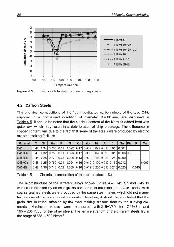
The effect of alloying elements on hot ductility is very important, since usually ma-chinability enhancing elements lead to a deterioration of hot ductility. This may cause problems in continuous casting and in hot rolling of the steel. Therefore, hot ductility tests were conducted for the 80 mm bars of all the six free cutting steels at Saarstahl AG (Völklingen, Germany). Tensile test specimens of a diameter D = 5 mm were heated up to 1280°C, held for 3 minutes and then cooled down in the furnace to the deformation temperature and tested at a deformation speed of 5 %/min. After frac-ture the reduction of area was measured and plotted according to Figure 4.3. All the materials show a typical ductility through with a minimum at 850°C where phase transformation takes place. The best hot ductility is obvious for a standard 11SMn30. The higher sulphur variant 11SMn37 is characterised by a slightly lower hot ductility comparable to 11SMn30+Sn. The values for the leaded steel and the high copper tin added variant are equal and lower compared to the before mentioned materials. The lowest hot ductility was measured for the bismuth added free cutting steel. In the re-gion of 850 – 1100°C the reduction of area for this grade always lay about 10 % lower than for all the other grades, at 850°C the reduction of area amounted only to 60 % of the value measured for the unleaded 11SMn30. Due to this difference in hot ductility it can be assumed that the bismuth added material has the worst rollability of all investigated free cutting steels.
20 4 Material Characterisation
0
10
20
30
40
5060
70
80
90
100
600 700 800 900 1000 1100 1200 1300
Temperature / °C
Redu
ctio
n of
are
a / % 11SMn37
11SMn30+Sn11SMn30+Sn+Cu11SMn3011SMnPb3011SMn30+Bi
11SMn3711SMn30+Sn11SMn30+Sn+Cu11SMn3011SMnPb3011SMn30+Bi
0
10
20
30
40
5060
70
80
90
100
600 700 800 900 1000 1100 1200 1300
Temperature / °C
Redu
ctio
n of
are
a / % 11SMn37
11SMn30+Sn11SMn30+Sn+Cu11SMn3011SMnPb3011SMn30+Bi
11SMn3711SMn30+Sn11SMn30+Sn+Cu11SMn3011SMnPb3011SMn30+Bi
Figure 4.3: Hot ductility data for free cutting steels
4.2 Carbon Steels
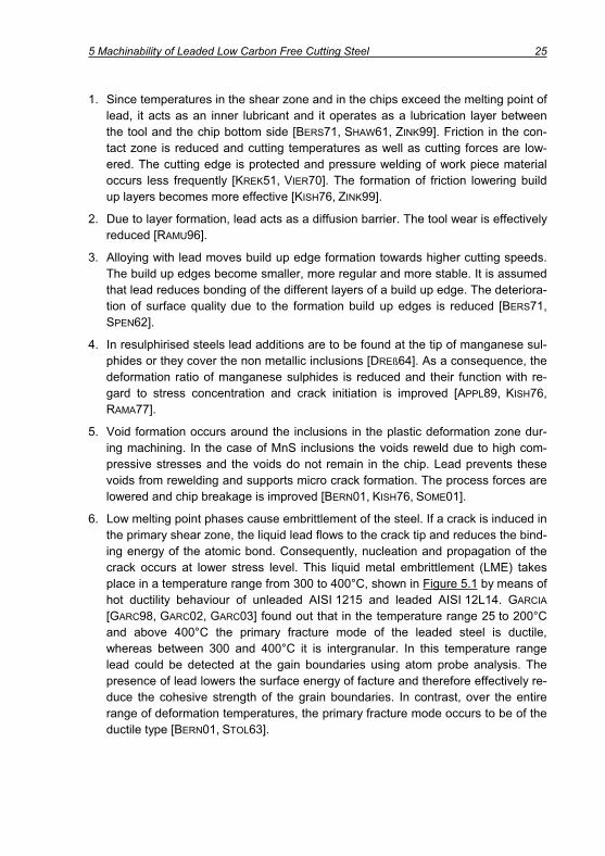
The chemical compositions of the five investigated carbon steels of the type C45, supplied in a normalised condition of diameter D = 60 mm, are displayed in Table 4.5. It should be noted that the sulphur content of the bismuth added heat was quite low, which may result in a deterioration of chip breakage. The difference in copper content was due to the fact that some of the steels were produced by electric arc steelmaking facilities.
Material C Si Mn P S Cr Mo Ni Al Cu Sn Pb Bi CaC45 0.44 0.34 0.785 0.01 0.022 0.17 0.037 0.029 0.018 0.018 0.001 C45+Pb 0.45 0.32 0.750 0.01 0.026 0.17 0.008 0.026 0.023 0.010 0.006 0.3 C45+Sn 0.45 0.25 0.770 0.02 0.028 0.13 0.020 0.110 0.021 0.250 0.090 C45+Ca 0.48 0.25 0.760 0.01 0.024 0.16 0.040 0.100 0.012 0.160 0.012 0.002 C45+Bi 0.42 0.36 0.740 0.02 0.006 0.16 0.012 0.250 0.015 0.210 0.023 0.045
Table 4.5: Chemical composition of the carbon steels (%)
The microstructure of the different alloys shows Figure 4.4. C45+Sn and C45+Bi were characterised by coarser grains compared to the other three C45 steels. Both coarse grained steels were produced by the same steel maker, which did not manu-facture one of the fine grained materials. Therefore, it should be concluded that the grain size is rather affected by the steel making process than by the alloying ele-ments. Hardness values were measured with 215HV30 for C45+Sn and 195 – 205HV30 for the other steels. The tensile strength of the different steels lay in the range of 685 – 700 N/mm2.

4 Material Characterisation 21
Cm45
C45+Pb
C45+Sn
C45+Ca
C45+Bi
250 μm
Longitudinal sectionnon-etched
Longitudinal sectionetched
Cross sectionetched
Cm45
C45+Pb
C45+Sn
C45+Ca
C45+Bi
250 μm
Longitudinal sectionnon-etched
Longitudinal sectionetched
Cross sectionetched
Figure 4.4: Metallographical sections of carbon steels
Hot ductility test were performed for the C45 steels except from the tin added variant at Saarstahl AG. Tensile test specimens (D = 5 mm) were reheated to 1300°C and then cooled down in the furnace to deformation temperature of 700 – 1150°C. At a constant deformation speed of 5 %/min the reduction of area was measured. Accord-ing to Figure 4.5, bismuth had a detrimental effect on hot ductility. At 1000°C the re-duction of area was about 40 % lower compared to the other materials, which showed similar results at this temperature. Respecting hot ductility in the range 750 – 900°C, the leaded steel was worse than standard C45 and C45+Ca, but still signifi-cantly better than C45+Bi. At 700°C the values for hot ductility of the bismuth steel was comparable to the values of C45+Pb and C45+Ca.

22 4 Material Characterisation
01020
3040506070
8090
100
600 700 800 900 1000 1100 1200 1300
Temperature / °C
Red
uctio
n of
are
a / %
C45+Ca
C45+Bi
C45 C45+Pb
01020
3040506070
8090
100
600 700 800 900 1000 1100 1200 1300
Temperature / °C
Red
uctio
n of
are
a / %
C45+Ca
C45+Bi
C45 C45+Pb
Figure 4.5: Hot ductility test results for carbon steels
4.3 Case Carburising Steels
Corresponding to the other steel groups, Table 4.6 summarises the chemical compo-sition of the four tested case carburising steels. The 60 mm diameter bars were given a normalising treatment. 16MnCr5+Sn was a laboratory melt produced at the Institute for Ferrous Metallurgy of RWTH Aachen (IEHK) using the listed 16MnCr5 steel as feedstock.
Material C Si Mn P S Cr Mo Ni Al Cu Sn Pb Bi 16MnCr5+Pb 0.167 0.190 1.158 0.018 0.029 1.051 0.019 0.083 0.029 0.027 0.002 0.23 16MnCr5 0.170 0.260 1.110 0.012 0.029 0.940 0.027 0.120 0.021 0.170 0.010 16MnCr5+Sn 0.150 0.150 1.100 0.009 0.025 1.000 0.020 0.110 0.019 0.170 0.050 16MnCr5+Bi 0.160 0.244 1.160 0.014 0.024 0.990 0.066 0.210 0.016 0.220 0.019 0.069
Table 4.6: Chemical composition of case carburising steels (%)
The microstructure (Figure 4.6) showed differences in the grain sizes and the align-ment of the microstructure. The non-specially alloyed 16MnCr5 was characterised by a coarse grained homogenous ferrite-pearlite microstructure. Its hardness was meas-ured with around 175HV30. The bismuth and lead added variants showed a banded structure with a lower grain size and lower hardness (170HV30 (Bi), 150HV30 (Pb)). Finally, the highest hardness was measured for the Sn added material with about 185HV30.
Comparable to hot ductility testing of the C45 steels, the industrial heats of the 16MnCr5 type were investigated. As displayed in Figure 4.7 the bismuth and lead alloyed carburising steels showed lower hot ductility compared with the standard grade. Considering the run of the hot ductility curve, a similar temperature influence could be seen for the leaded and the bismuth alloyed steel.

4 Material Characterisation 23
16MnCr5
16MnCr5+Pb
16MnCr5+Sn
16MnCr5+Bi
250 μm
Longitudinal sectionnon-etched
Longitudinal sectionetched
Cross sectionetched
16MnCr5
16MnCr5+Pb
16MnCr5+Sn
16MnCr5+Bi
250 μm250 μm
Longitudinal sectionnon-etched
Longitudinal sectionetched
Cross sectionetched
Figure 4.6: Microstructure of different case carburising steels
0
10
20
30
40
5060
70
80
90
100
600 700 800 900 1000 1100 1200 1300
Temperature / °C
Redu
ctio
n of
are
a / %
16MnCr516MnCr5+Pb
16MnCr5+Bi
0
10
20
30
40
5060
70
80
90
100
600 700 800 900 1000 1100 1200 1300
Temperature / °C
Redu
ctio
n of
are
a / %
16MnCr516MnCr5+Pb
16MnCr5+Bi
16MnCr516MnCr5+Pb
16MnCr5+Bi
16MnCr516MnCr5+Pb
16MnCr5+Bi
Figure 4.7: Hot ductility data for case carburising steels

24 5 Machinability of Leaded Low Carbon Free Cutting Steel
5 Machinability of Leaded Low Carbon Free Cutting Steel
The investigation of machinability of different alloyed free cutting steels is this work’s objective. In order to provide a basis for rating the machinability of the various mate-rials, firstly the performance of a standard leaded low carbon free cutting steel of the type 11SMnPb30 is characterised in turning tests. As initially mentioned the main criteria for rating the machinability are process forces, surface quality, chip forms and tool wear. For this reason, the chapters are going to be structured according to these criteria.
5.1 Properties, Characteristics and Functions of Lead in Cutting
Already in the beginning of the 20th century, RÜBEL recommended the addition of 1 % lead to steel in order to improve machinability [RUEB11]. In the following decades many researchers investigated and discussed the functions of lead in the cutting process and came to the conclusion that 0.15 to 0.35 % lead is a proper quantity for machinability enhancement. However, bringing lead into the melted steel is difficult since lead is characterised by a melting point of only S, Pb = 327°C (Table 5.1) and a vaporising point of about 1700°C, respectively 1500°C as an oxide [DREß64]. Further, lead counts among the heavy metals with a higher density than steel. For the con-ventional steel making process, this means that lead would settle on the ground of the melting pot or vaporise under release of toxic fumes. Therefore, the steel making process of leaded steels is different from non-leaded steels and specific fume ex-haust facilities are necessary [BERS71, BSW05, DREß64, STAH06, WIKI06]. However, once the desired amount is brought into the steel, lead appears as sub microscopic inclusions due to a very low solubility in steel [KOEN02]. The mechanical and techno-logical properties of the work piece material are not deteriorated significantly due to alloying with lead at low temperatures [DREß64]. Nevertheless, the decrease of ten-sile strength and toughness in the temperature range of 250 – 400°C is stronger compared to non-leaded steels as a result of the low melting point of lead. Due to this detrimental effect on ductility, leaded steel should not be used at temperatures greater than 200°C [FAUL98, VIER70].
Ele-ment
Melting Point /
°C
Vapor. Point /
°C
Density / (g/cm3)
Thermal conduct. / (W/(m*K))
SpecificHeat /
(J/(kg*K))
Melting heat /
(kJ/mol)
Vaporis. heat/
(kJ/mol)
Pb 327 1700 11.34 35 129 4.8 177.7
Table 5.1: Physical properties of lead [LDAI05, SEIL06]
The effectiveness of lead in cutting processes is described by six approaches. Hereby the functions of lead regarding the generation of low cutting forces, short breaking chips, low tool wear and high surface quality are the focus:
5 Machinability of Leaded Low Carbon Free Cutting Steel 25
1. Since temperatures in the shear zone and in the chips exceed the melting point of lead, it acts as an inner lubricant and it operates as a lubrication layer between the tool and the chip bottom side [BERS71, SHAW61, ZINK99]. Friction in the con-tact zone is reduced and cutting temperatures as well as cutting forces are low-ered. The cutting edge is protected and pressure welding of work piece material occurs less frequently [KREK51, VIER70]. The formation of friction lowering build up layers becomes more effective [KISH76, ZINK99].
2. Due to layer formation, lead acts as a diffusion barrier. The tool wear is effectively reduced [RAMU96].
3. Alloying with lead moves build up edge formation towards higher cutting speeds. The build up edges become smaller, more regular and more stable. It is assumed that lead reduces bonding of the different layers of a build up edge. The deteriora-tion of surface quality due to the formation build up edges is reduced [BERS71,SPEN62].
4. In resulphirised steels lead additions are to be found at the tip of manganese sul-phides or they cover the non metallic inclusions [DREß64]. As a consequence, the deformation ratio of manganese sulphides is reduced and their function with re-gard to stress concentration and crack initiation is improved [APPL89, KISH76,RAMA77].
5. Void formation occurs around the inclusions in the plastic deformation zone dur-ing machining. In the case of MnS inclusions the voids reweld due to high com-pressive stresses and the voids do not remain in the chip. Lead prevents these voids from rewelding and supports micro crack formation. The process forces are lowered and chip breakage is improved [BERN01, KISH76, SOME01].
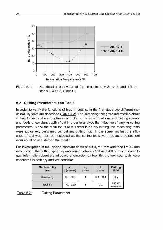
6. Low melting point phases cause embrittlement of the steel. If a crack is induced in the primary shear zone, the liquid lead flows to the crack tip and reduces the bind-ing energy of the atomic bond. Consequently, nucleation and propagation of the crack occurs at lower stress level. This liquid metal embrittlement (LME) takes place in a temperature range from 300 to 400°C, shown in Figure 5.1 by means of hot ductility behaviour of unleaded AISI 1215 and leaded AISI 12L14. GARCIA
[GARC98, GARC02, GARC03] found out that in the temperature range 25 to 200°C and above 400°C the primary fracture mode of the leaded steel is ductile, whereas between 300 and 400°C it is intergranular. In this temperature range lead could be detected at the gain boundaries using atom probe analysis. The presence of lead lowers the surface energy of facture and therefore effectively re-duce the cohesive strength of the grain boundaries. In contrast, over the entire range of deformation temperatures, the primary fracture mode occurs to be of the ductile type [BERN01, STOL63].
26 5 Machinability of Leaded Low Carbon Free Cutting Steel
0
10
20
30
40
50
60
0 100 200 300 400 500 600 700
Deformation Temperature / °C
Bul
k D
efor
mat
ion
/ %
AISI 1215AISI 12L14
0
10
20
30
40
50
60
0 100 200 300 400 500 600 700
Deformation Temperature / °C
Bul
k D
efor
mat
ion
/ %
AISI 1215AISI 12L14AISI 1215AISI 12L14AISI 1215AISI 12L14
Figure 5.1: Hot ductility behaviour of free machining AISI 1215 and 12L14 steels [GARC98, GARC03]
5.2 Cutting Parameters and Tools
In order to verify the functions of lead in cutting, in the first stage two different ma-chinability tests are described (Table 5.2). The screening test gives information about cutting forces, surface roughness and chip forms at a broad range of cutting speeds and feeds at constant depth of cut in order to analyse the influence of varying cutting parameters. Since the main focus of this work is on dry cutting, the machining tests were exclusively performed without any cutting fluid. In the screening test the influ-ence of tool wear can be neglected as the cutting tools were replaced before tool wear could have disturbed the results.
For investigation of tool wear a constant depth of cut ap = 1 mm and feed f = 0.2 mm was chosen, the cutting speed vc was varied between 100 and 200 m/min. In order to gain information about the influence of emulsion on tool life, the tool wear tests were conducted in both dry and wet condition.
Machinability test
vc/ (m/min)
ap/ mm
f/ mm
Cuttingfluid
Screening 60 - 300 1 0.1 – 0.4 Dry
Tool life 100; 200 1 0.2 Dry or emulsion
Table 5.2: Cutting Parameters

5 Machinability of Leaded Low Carbon Free Cutting Steel 27
Plane inserts from cemented carbide with the specification SPUN 120304 were used for the mentioned fundamental machining tests (Table 5.3). The tools with a nose radius r = 0.4 mm showed a positive rake angle of = 6° and a clearance angle of
= 5°, the lead angle was r = 75° and the inclination angle amounted = 0°. The surfaces of these indexable inserts were plane in order to enable the observation of chip breakage in external turning based solely on the material properties and not on a specific chip breaking geometry. Further, these inserts allow for statements regard-ing the friction conditions based on the process forces as the rake angle is constant and does not change as a result of the chip forming geometry of the insert.
As uncoated cemented carbide insert a WC-(Ti, Ta, Nb)C-Co cutting material accord-ing to the classification HW-P10 was chosen. Within the uncoated WC-Co sub-strates, this cutting material can be characterised by high wear resistance and good temperature strength due to an increased share of composite carbides on the basis of Ti, Ta and Nb. The substrate of the coated insert was also from a WC-(Ti, Ta, Nb)C-Co composition, which showed a bit more toughness and less temperature re-sistance due to a reduced share of composite carbides. Surface hardness and tem-perature resistance were increased by the coating.
Denotation Cuttingmaterial Coating r rn r
SPUN120304 HW-P10 75° 6° 5° 0° 24 μm 0,4 mm
SPUN120304 HC-P30 Ti(C,N)/Al203/TiN 75° 6° 5° 0° 50 μm 0,4 mm
Table 5.3: Specification of cutting inserts for machinability test
The 13 μm thick CVD-multilayer coating contained Ti(C,N), Al2O3 and TiN (Figure 5.2). The Ti(C,N)-layer with a thickness of s = 5 μm is located between the highly chemical and temperature resistant Al2O3-layer (s = 7 μm) and the substrate material since adhesion of the substrate and Ti(C,N) is better compared to Al2O3. In order to lower friction on rake and flank and to give the tool the typical golden look, the thin (s = 0.9 μm) top layer is from TiN. Furthermore, at room temperature TiN shows with up to 2700HV0.05 higher hardness compared to Al2O3 with 2200HV0.05 at maximum [FREY87, KOEN02, SALM83, TOEN95].

28 5 Machinability of Leaded Low Carbon Free Cutting Steel
TiN
Substrate
Ti(C,N)
Al2O3
Rake
Flank
rn = 50 μm
50 μm 10 μm
TiN
Substrate
Ti(C,N)
Al2O3
Rake
Flank
rn = 50 μm
50 μm 10 μm
Figure 5.2: Section of the insert with CVD-coating from Ti(C,N)/Al2O3/TiN
Apparently, the cutting edge radius of the coated insert was quite large with rn = 50 μm. In turning SOKOLOWSKI [SOKO55] found out that the ratio of uncut chip thickness and cutting edge radius should not drop below the factor 1.125 to guaran-tee proper chip formation. Accordingly, the maximum cutting edge radius for machin-ing tests at the cutting conditions given in Table 5.2 can be calculated as follows:
125.1r
h
maxn,
Equation 5.1
μm85125.1sinf
125.1hr r
maxn,
Thus, the actual cutting edge radius of the coated inserts (rn = 50 μm) does not ex-ceed this calculated critical value rn, max. Nevertheless, an influence of the large cut-ting edge radius on the chip formation process and particularly on process forces should not be neglected.
5.3 Screening of 11SMnPb30
5.3.1 Process Forces
Process forces were measured using a three component force dynamometer. The cutting length performed with one insert was short in order to guarantee that tool wear did not affect the measurements. The results from turning 11SMnPb30 with un-coated tools at different feeds and speeds are shown in Figure 5.3.

5 Machinability of Leaded Low Carbon Free Cutting Steel 29
50
150
250
350
450
550
650
0
50
100
150
200
250
0 50 100 150 200 250 300 350 0 50 100 150 200 250 300 350Cutting speed vc / (m/min) Cutting speed vc / (m/min)
Forc
e F
/ NFo
rce
F / N
Cutting force
Feed force Thrust force
Work material: 11SMnPb30
Cutting tool: SPUN120304
Tool material: HW-P10
Depth of cut: ap = 1 mm
Coolant: dry
Cutting length: lc = 20 mm
f = 0.2 mm
f = 0.1 mm
f = 0.4 mm
50
150
250
350
450
550
650
0
50
100
150
200
250
0 50 100 150 200 250 300 350 0 50 100 150 200 250 300 350Cutting speed vc / (m/min) Cutting speed vc / (m/min)
Forc
e F
/ NFo
rce
F / N
Cutting force
Feed force Thrust force
Work material: 11SMnPb30
Cutting tool: SPUN120304
Tool material: HW-P10
Depth of cut: ap = 1 mm
Coolant: dry
Cutting length: lc = 20 mm
f = 0.2 mm
f = 0.1 mm
f = 0.4 mm
Figure 5.3: Forces in dry turning 11SMnPb30 with uncoated carbide inserts
It is obvious that the forces in machining at the highest of the three applied feeds showed maximum values due to the increased amount of material volume machined during one rotation. Arranging the different force components regarding their values, the cutting force came at first, at second the feed force and at last the thrust force. The values of feed and thrust force were strongly influenced by the lead angle
r = 75°, which determines the direction of the resulting force vector. According to Figure 5.3 the influence of cutting speed was significant for all force components as each force curve showed a similar run for one specific feed. Nevertheless, feed and thrust force were characterised by stronger dependency on cutting speed compared to the cutting force. In all plots a significant rise was found, whereby the respective cutting speed, where the rise appeared, depended on the applied feed. In turning at low feed of f = 0.1 mm, the increase in forces could be observed at a speed of vc = 140 m/min. Rising the cutting speed from 140 to 180 m/min resulted in an in-crease of cutting force by 15 %, thrust force by 44 % and feed force by 51 %. Even steeper rises could be detected at the medium feed of f = 0.2 mm. Between 80 and 100 m/min the feed force raised from 73 to 127 N, which corresponds to 73 %. The range of transition cutting speeds, where the rise in forces could be measured as well as the percentage characterising the increase are displayed in Table 5.4.

30 5 Machinability of Leaded Low Carbon Free Cutting Steel
Feed Transition cutting speed Increase
0.1 mm 140 – 180 m/minCutting force + 15 % Feed force + 51 % Thrust Force + 44 %
0.2 mm 80 – 100 m/min Cutting force + 15 % Feed force + 73 % Thrust Force + 54 %
0.4 mm 60 – 80 m/min Cutting force + 4 % Feed force + 20 % Thrust Force + 17 %
Table 5.4: Cutting speeds and percentage characterising force increase in turning with uncoated tools (HW-P10; ap = 1 mm)
Cutting, feed and thrust force are the components of the resulting cutting force, which are measured in the Cartesian machine coordinate system and thus act in those planes described by the cutting speed and feed vector (Fc, Ff) or respectively or-thogonal to it (Fp). However, the forces describing the loads on the cutting tool are the normal and tangential forces F n and F t. These forces can be calculated by means of a coordinate transformation from the machine system to the cutting tool system. Using a transformation matrix A, the combination of the different coordinate systems can be established [KLOS93, ZIEB95]:
Tcfp
Tntt FFFAFFF ),,(),,( Equation 5.2
Actually, the coordinate transformation is a rotation of the machine coordinate system with the tool angles and . Hence, the transformation matrix A is the product of the rotary matrices A A and A (Figure 5.4).
For the applied cutting tools according to Table 5.3 ( = 0°) the calculation can be simplified and the normal and tangential forces can be determined:
sin)cosFsin(FcosFF rprfcn Equation 5.3
cos)cosFsin(FsinFF rprfct Equation 5.4
By means of normal and tangential forces a force ratio k can be calculated as fol-lows:
sin)cosFsin(FcosFcos)cosFsin(FsinF
FF
krprfc
rprfc
n
t Equation 5.5
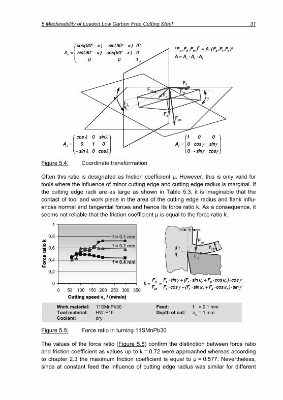
5 Machinability of Leaded Low Carbon Free Cutting Steel 31
Fc F n
Ff
Fp
F tF t
AAAA)F,F,F(A)F,F,F( T
cfpT
ntt
100
0)90(cos)90(sin-
0)90sin()90cos(
A
cos0
sin
010
sin0
cosA
cossin
0
sin-cos
0
001
A
Fc F n
Ff
Fp
F tF t
AAAA)F,F,F(A)F,F,F( T
cfpT
ntt
100
0)90(cos)90(sin-
0)90sin()90cos(
A
cos0
sin
010
sin0
cosA
cossin
0
sin-cos
0
001
A
Figure 5.4: Coordinate transformation
Often this ratio is designated as friction coefficient μ. However, this is only valid for tools where the influence of minor cutting edge and cutting edge radius is marginal. If the cutting edge radii are as large as shown in Table 5.3, it is imaginable that the contact of tool and work piece in the area of the cutting edge radius and flank influ-ences normal and tangential forces and hence its force ratio k. As a consequence, it seems not reliable that the friction coefficient μ is equal to the force ratio k.
sin)cosFsin(FcosFcos)cosFsin(FsinF
FF
krprfc
rprfc
n
t0
0,2
0,4
0,6
0,8
1
0 50 100 150 200 250 300 350Cutting speed vc / (m/min)
Forc
e ra
tiok
f = 0.2 mm
f = 0.1 mm
f = 0.4 mm
hch
h
F n
F t
Work material: 11SMnPb30 Feed: f = 0.1 mmTool material: HW-P10 Depth of cut: ap = 1 mmCoolant: dry
sin)cosFsin(FcosFcos)cosFsin(FsinF
FF
krprfc
rprfc
n
t0
0,2
0,4
0,6
0,8
1
0 50 100 150 200 250 300 350Cutting speed vc / (m/min)
Forc
e ra
tiok
f = 0.2 mm
f = 0.1 mm
f = 0.4 mm
hch
h
F n
F t
Work material: 11SMnPb30 Feed: f = 0.1 mmTool material: HW-P10 Depth of cut: ap = 1 mmCoolant: dry
Figure 5.5: Force ratio in turning 11SMnPb30
The values of the force ratio (Figure 5.5) confirm the distinction between force ratio and friction coefficient as values up to k = 0.72 were approached whereas according to chapter 2.3 the maximum friction coefficient is equal to μ = 0.577. Nevertheless, since at constant feed the influence of cutting edge radius was similar for different

32 5 Machinability of Leaded Low Carbon Free Cutting Steel
cutting speeds, a considerable influence of friction on the force ratio was existent and the k value conduced to interpret the conditions in the contact zone. Thus, it can be taken as an indication for friction whereas it does not represent the friction coefficient.
Figure 5.5 displays that the strongest influence of cutting speed on the force ratio is obvious at low feed. At slow velocity an improvement of the contact conditions took place whereas at transition speeds according to Table 5.4 a tremendous change in contact conditions occurred. The examination of chips using SEM showed white globular residues on the bottom side of the chips (Figure 5.6). An EDX-analysis clari-fied that these spherical parts were composed of lead. Hence, lead was liquefied as a result of its low melting point (327°C) in combination with temperatures, which reached their maximum values in the contact zone of rake and bottom side of the chip. Liquid lead supported the sliding movement of the chip on the rake. The sliding chip took lead out of the contact zone where it solidified again and therefore adhered to the bottom side of the chips in globular shape.
vc = 100 m/min vc = 200 m/min
Work material: 11SMnPb30 Feed: f = 0.1 mmTool material: HW-P10 Depth of cut: ap = 1 mmCoolant: dry
25 μm25 μm
100 μm100 μm
PbPb
vc = 100 m/min vc = 200 m/min
Work material: 11SMnPb30 Feed: f = 0.1 mmTool material: HW-P10 Depth of cut: ap = 1 mmCoolant: dry
25 μm25 μm
100 μm100 μm
PbPb
Figure 5.6: Bottom side of chips showing spherical lead residues
The left part of Figure 5.6 shows the bottom side of a chip from turning at vc = 100 m/min and f = 0.1 mm. According to Figure 5.3 and Figure 5.5 these cutting conditions were characteristically for low process forces and a low calculated force ratio, which indicates good friction conditions. The white lead residues were distrib-uted over the whole bottom side of the chip. In contrast, a chip from cutting at 200 m/min, respectively in that range of cutting conditions characterised by highly raised level of forces and friction, showed only very few lead residues.
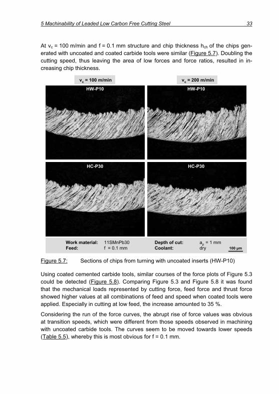
5 Machinability of Leaded Low Carbon Free Cutting Steel 33
At vc = 100 m/min and f = 0.1 mm structure and chip thickness hch of the chips gen-erated with uncoated and coated carbide tools were similar (Figure 5.7). Doubling the cutting speed, thus leaving the area of low forces and force ratios, resulted in in-creasing chip thickness.
HC-P30
HW-P10
Work material: 11SMnPb30 Depth of cut: ap = 1 mmFeed: f = 0.1 mm Coolant: dry
vc = 200 m/minvc = 100 m/min
HC-P30
HW-P10
100 μm
HC-P30
HW-P10
Work material: 11SMnPb30 Depth of cut: ap = 1 mmFeed: f = 0.1 mm Coolant: dry
vc = 200 m/minvc = 100 m/min
HC-P30
HW-P10
100 μm
Figure 5.7: Sections of chips from turning with uncoated inserts (HW-P10)
Using coated cemented carbide tools, similar courses of the force plots of Figure 5.3 could be detected (Figure 5.8). Comparing Figure 5.3 and Figure 5.8 it was found that the mechanical loads represented by cutting force, feed force and thrust force showed higher values at all combinations of feed and speed when coated tools were applied. Especially in cutting at low feed, the increase amounted to 35 %.
Considering the run of the force curves, the abrupt rise of force values was obvious at transition speeds, which were different from those speeds observed in machining with uncoated carbide tools. The curves seem to be moved towards lower speeds (Table 5.5), whereby this is most obvious for f = 0.1 mm.

34 5 Machinability of Leaded Low Carbon Free Cutting Steel
50
150
250
350
450
550
650
0 50 100 150 200 250 300 350
0
50
100
150
200
250
0 50 100 150 200 250 300 350 0 50 100 150 200 250 300 350Cutting speed vc / (m/min) Cutting speed vc / (m/min)
Forc
e F
/ NFo
rce
F / N
Cutting force
Feed force Thrust force
f = 0.2 mm
f = 0.1 mm
f = 0.4 mm Work material: 11SMnPb30
Cutting tool: SPUN120304
Tool material: HC-P30
Depth of cut: ap = 1 mm
Coolant: dry
50
150
250
350
450
550
650
0 50 100 150 200 250 300 350
0
50
100
150
200
250
0 50 100 150 200 250 300 350 0 50 100 150 200 250 300 350Cutting speed vc / (m/min) Cutting speed vc / (m/min)
Forc
e F
/ NFo
rce
F / N
Cutting force
Feed force Thrust force
f = 0.2 mm
f = 0.1 mm
f = 0.4 mm Work material: 11SMnPb30
Cutting tool: SPUN120304
Tool material: HC-P30
Depth of cut: ap = 1 mm
Coolant: dry
Figure 5.8: Forces in dry turning of 11SMnPb30 with coated carbide inserts
In machining at a feed f = 0.4 mm a rise in forces between 60 and 100 m/min could be observed, but it is not obvious, where the range of cutting speeds characterised by lower forces ends. Therefore, the values characterising the force increase at the highest investigated feed were not included into Table 5.5. Regarding the increase of each force component it can be mentioned, that in cutting with coated tools, the rise was always stronger compared to machining with uncoated tools. Particularly, at a feed of f = 0.2 mm the thrust force increased by 84 % and the feed force even by 110 % from 70 to 147 N.
Feed Transition cutting speed Increase
0.1 mm 80 – 120 m/minCutting force + 20 % Feed force + 70 % Thrust Force + 61 %
0.2 mm 60 – 100 m/min Cutting force + 23 % Feed force + 110 % Thrust Force + 84 %
Table 5.5: Cutting speeds and percentage characterising force increase in turning with coated tools (HC-P30; ap = 1 mm)

5 Machinability of Leaded Low Carbon Free Cutting Steel 35
5.3.2 Surface Quality
The surface quality was measured with a tactile gauge MAHR Perthometer S8P at all feed and speed combinations. In turning 11SMnPb30 with uncoated carbide tools at a feed of 0.1 mm the arithmetic mean value Ra varied from 1.13 to 2.13 μm and the peak to valley height Rz from 8.44 to 12.39 μm (Figure 5.9). Turning at an elevated feed of 0.2 mm resulted in increased surface roughness values in the range of Ra = 3.68 - 5.58 μm and Rz = 17.85 - 27.89 μm. This can be explained by the rise of kinematic roughness Rkin, which is caused by the relative movement of tool and work piece and mainly determined by the applied feed per revolution (Equations 5.6 and 5.7).
4
22 frrRkin Equation 5.6
or simplified
r8fR
2
kin Equation 5.7
A further increase of the feed to f = 0.4 mm led to surface qualities of about Ra = 12 μm and Rz = 50 μm. Since a feed of 0.4 mm is typical for a roughing opera-tion, the surface quality was not of substantial interest and consequently the values are not displayed in the respective figures.
0
1
2
3
4
5
6
0 50 100 150 200 250 300 3500
5
10
15
20
25
30
0 50 100 150 200 250 300 350
Surf
ace
roug
hnes
s/ μ
m
Cutting speed vc / (m/min) Cutting speed vc / (m/min)
Arithmetic mean value Ra Peak to valley height Rz
Work material: 11SMnPb30 Depth of cut: ap = 1 mmCutting tool: SPUN120304 Coolant: dry
f = 0.2 mm
f = 0.1 mm
HW
HC
Figure 5.9: Surface Quality in turning of 11SMnPb30 with uncoated tools (HW-P10) and coated inserts (HC-P30)
Beneath the wide influence of feed, also the cutting speed impacted the surface qual-ity. With increasing cutting speed an improvement of surface quality could be ob-served. In cutting with coated tools the influence of cutting speed was less important regarding the arithmetic mean value Ra whereas the roughness characteristic Rz

36 5 Machinability of Leaded Low Carbon Free Cutting Steel
showed a stronger dependency on cutting speed. Obviously, the application of coated inserts led to improved surface quality in nearly the whole range of cutting speeds and feeds.
For investigating the mechanisms which were responsible for the downward drift of the roughness value in dependency of cutting speed, SEM images of machined sur-faces gave first information. Figure 5.10 shows surfaces generated at different cut-ting speed. The small boxes describe the areas, which are illustrated by the magni-fied photo in the respective left top corner. In order to specify the topography, secon-dary beam images were chosen for the zoomed view. Along the feed marks the work piece surfaces appeared very irregularly, which accords to the measurement of the peak to valley height Rz. As shown in the left part of Figure 5.10, only very few parts of the work piece obtained the typical smooth surface, which is generated when the material is separated due to shearing (dark areas). The bigger part was character-ised by a kind of texture which is typical for brittle fracture behaviour for a kind of ploughing process.
Work material: 11SMnPb30 Feed: f = 0.1 mmTool material: HC-P30 Depth of cut: ap = 1 mmCoolant: dry
vc = 100 m/min vc = 200 m/min
200 μm200 μm
80 μm80 μm
Work material: 11SMnPb30 Feed: f = 0.1 mmTool material: HC-P30 Depth of cut: ap = 1 mmCoolant: dry
vc = 100 m/min vc = 200 m/min
200 μm200 μm
80 μm80 μm
Figure 5.10: Surfaces generated at vc = 100 m/min and 200 m/min
Similar results could be observed in turning at higher feed as again the surfaces be-came more and more uniform with increasing speed. Compared to f = 0.1 mm, in machining at f = 0.2 mm the influence of the kinematical surface roughness was higher and therefore the influence of cutting speed on surface quality was less sig-nificant as in machining at f = 0.1 mm.

5 Machinability of Leaded Low Carbon Free Cutting Steel 37
5.3.3 Chip Formation Process
Detailed information about the chip formation process was gained by means of chip roots. Therefore a quick-stop device came into operation, which allows for a sudden stop of the cutting process by knocking the insert off the work piece [LOLA49,BUDA68]. This is achieved by a powder actuated fastening tool, which accelerates a bolt towards the pivoted tool holder. The tool holder bears on a shearing pin with rated break points, where breakage is initiated when the bolt hits the tool with a strong impulse. Hence, the insert is shot off the process and chip roots can be gen-erated in the continuous state of cutting (Figure 5.11).
vc
Before the shot After the shot
Fastening tool
Bolt
Workpiece
Tool holder
Insert
Shearing pin
Chip root
vc
Before the shot After the shot
Fastening tool
Bolt
Workpiece
Tool holder
Insert
Shearing pin
Chip root
Figure 5.11: Generation of chip roots using a quick stop device
The left part of Figure 5.12 provides a view on the bottom side of a chip root gener-ated at vc = 100 m/min and f = 0.1 mm. The irregular topography of the machined work piece surface is visible as good as the uneven bottom side of the chip. At the end of the contact zone a shear fracture occurred. The chip proceeded with its chip velocity vch, whereas the detached part of the chip material could not be directly car-ried away by chip or work piece and adhered to the tool. This is a kind of initiation point as a build up edge will form subsequently by single work material layers [PRIM69]. At this point the irregular topography of the chip bottom side was formed (Figure 5.12, right) as the chip had to move over the irregular adherences on the tool.
Using chip roots it could be proved that build up edge formation was to be reduced in two ways. One approach was an increase of cutting speed and the other possibility could be seen in the application of coated tools.

38 5 Machinability of Leaded Low Carbon Free Cutting Steel
1 Chip bottom side 2 Build up edge3 Raw work piece surface 4 Machined work piece surface5 Trace of the major cutting edge
Work material: 11SMnPb30 Tool material: HC-P30 Cutting speed: vc = 100 m/min Feed: f = 0.1 mmDepth of cut: ap = 1 mm Coolant: dry
1
5
4
3
1
2
2vch
50 μm400 μmView
1 Chip bottom side 2 Build up edge3 Raw work piece surface 4 Machined work piece surface5 Trace of the major cutting edge
Work material: 11SMnPb30 Tool material: HC-P30 Cutting speed: vc = 100 m/min Feed: f = 0.1 mmDepth of cut: ap = 1 mm Coolant: dry
1
5
4
3
1
2
2vch
50 μm400 μm400 μmViewView
Figure 5.12: SEM view of a chip root from cutting at vc = 100 m/min
As the left part of Figure 5.13 illustrates, a rise in cutting speed to vc = 200 m/min resulted in significantly more regular chip formation. Both, chip bottom side as well as machined work piece surface were quite even and did not show any impact of build up edge formation. In contrast the chip root taken in cutting with an uncoated carbide insert (Figure 5.13, right) still showed some influence of build up edge formation. Nevertheless, these small areas of work material adhesion were only visible in the area of the nose radius, thus in the area where the mechanical and thermal loads were believed to be lower as a result of low uncut chip thickness. The strong bonding of the work piece material with the cutting tool could be visualised by the strongly magnified view in the bottom of Figure 5.13. The white residues are parts of the cut-ting material, which were still connected to the steel adhesions after knocking the cutting edge off the chip formation process.

5 Machinability of Leaded Low Carbon Free Cutting Steel 39
HW-P10
Work material: 11SMnPb30
Cutting tool: SPUN120304
Tool material: HW-P10, HC-P30
Cutting speed: vc = 200 m/min
Feed: f = 0.1 mm
Depth of cut: ap = 1 mm
Coolant: dry
HC-P30
200 μm200 μm
20 μm
HW-P10HW-P10
Work material: 11SMnPb30
Cutting tool: SPUN120304
Tool material: HW-P10, HC-P30
Cutting speed: vc = 200 m/min
Feed: f = 0.1 mm
Depth of cut: ap = 1 mm
Coolant: dry
HC-P30
200 μm200 μm200 μm200 μm
20 μm20 μm
Figure 5.13: Chip roots from machining 11SMnPb30 at vc = 200 m/min
5.3.4 Chip Forms
Chip forms are quite important as long chips may cause disturbances in automated manufacturing systems, possibly deteriorate surface quality and also endanger the safety of the machine operator. Further, chip jamming may cause non expectable chip breakage. Today commercial inserts have chip forming elements, but special tools, which are often subject to re-grinding, do not show any elements leading to chip breakage. Usually these tools have plane surfaces and they are applied with positive rake angles in order to keep the forces on a low level.
Although plane inserts with a positive rake angle came into operation, at all combina-tions of speeds and feeds chip breaking problems did not occur. Using uncoated in-serts, at all cutting speeds at f = 0.1 mm and at lower speeds at f = 0.2 mm a mixture of short tubular and long comma chips could be observed (Figure 5.14, left). Rising the cutting speed at f = 0.2 mm resulted in stronger curling and improved breaking of the chips (Figure 5.14, right).

40 5 Machinability of Leaded Low Carbon Free Cutting Steel
vc = 200 m/min
Work material: 11SMnPb30 Cutting tool: SPUN120304Tool material: HW-P10 Feed: f = 0.2 mmCoolant: dry Depth of cut: ap = 1 mm
vc = 100 m/min
20 mm
vc = 200 m/min
Work material: 11SMnPb30 Cutting tool: SPUN120304Tool material: HW-P10 Feed: f = 0.2 mmCoolant: dry Depth of cut: ap = 1 mm
vc = 100 m/min
20 mm
Figure 5.14: Chip forms in cutting 11SMnPb30 at vc = 100 and 200 m/min
In the fracture area of the chip spherical lead residues (white) could be detected us-ing the EDX analysis (Figure 5.15). Very small lead particles with diameters of about 1 μm were distributed over the cross section of the chip. Nevertheless, also com-paratively large lead residues of about 3.5 μm diameter could be found. As already seen for the bottom side of the chips, lead was melted during cutting and solidified again at the surface of the chip, which shows that the liquefaction of lead was benefi-cial for chip fracture.
Work material: 11SMnPb30 Feed: f = 0.1 mmTool material: HW-P10 Depth of cut: ap = 1 mmCutting speed: vc = 200 m/min Coolant: dry
Pb
10 μm500 μm
Work material: 11SMnPb30 Feed: f = 0.1 mmTool material: HW-P10 Depth of cut: ap = 1 mmCutting speed: vc = 200 m/min Coolant: dry
Pb
10 μm500 μm
Work material: 11SMnPb30 Feed: f = 0.1 mmTool material: HW-P10 Depth of cut: ap = 1 mmCutting speed: vc = 200 m/min Coolant: dry
Pb
10 μm500 μm
Figure 5.15: Fracture area of a chip with spherical white lead residues
The transition from tubular to comma chips at elevated speeds in cutting at f = 0.2 mm, could be noticed in machining with coated tools also at a feed of 0.1 mm. Exceeding the feed to f = 0.4 mm only long comma chips were generated.

5 Machinability of Leaded Low Carbon Free Cutting Steel 41
5.4 Tool Wear Testing of 11SMnPb30
In the tool wear tests flank wear at the major and minor cutting edge and at the cor-ner of both cutting edges (nose radius) was documented according to ISO3685 [ISO3685]. A comparison of the respective values identified the appraisal criterion for tool wear development. After 76 minutes dry turning at vc = 100 m/min, the uncoated insert showed only VBB = 94 μm at the major flank, VBC = 145 μm at the cutting edge corner and VBNS = 251 μm at the minor cutting edge. Thus, the minor cutting edge determined the end of tool life, which was initially defined by a width of wear land of 250 μm. The quite uniform tool wear progression is illustrated in the left part of Figure 5.16.
VBB
,C,N
S/ μ
m
0
50
100
150
200
250
300
0 10 20 30 40 50 60 70 80
tc = 76 min
Cutting time tc / min
VBNS
VBC
VBB
Work material: 11SMnPb30 Feed: f = 0.2 mmCoolant: dry Depth of cut: ap = 1 mm
VBB
,C,N
S/ μ
m
0
50
100
150
200
250
300
0 10 20 30 40 50 60 70 80
tc = 76 min
Cutting time tc / min
VBNS
VBC
VBB
Work material: 11SMnPb30 Feed: f = 0.2 mmCoolant: dry Depth of cut: ap = 1 mm
Figure 5.16: Tool wear development in cutting 11SMnPb30 with uncoated ce-mented carbide HW-P10 at vc = 100 m/min
With increasing cutting time flank wear at the minor cutting edge rose strongest and a distinctive notch was formed at the minor, a very small notch at the major cutting edge (Figure 5.16, right). In both cases, the location of the notch was determined by the end of the contact zone of tool and work piece, respectively by the depth of cut at the major edge and by the feed at the minor cutting edge (Figure 5.17, left).
The wear seems to be linked to build up edge formation, which is illustrated by SEM images in Figure 5.17. The cutting process was suddenly interrupted using the quick stop device according to chapter 5.3.3. The chip was torn off the work piece material in the area of the primary shear zone, so that the build up edge still adhered to the work piece and could be made visible. Nevertheless, in the area of the major cutting edge parts of the build up edges were also torn away (left image). The build up edge overhang, which acted as the cutting edge, is clearly visible in the higher magnified images (two different viewing angles) at the right side of Figure 5.17. Work piece ma-terial adhered over the whole edge radius and covered parts of both rake and flank (image down right).

42 5 Machinability of Leaded Low Carbon Free Cutting Steel
a p=
1 m
m
f = 0.2 mm
tool
workpiece
r = 0.4 mm
= 75°
Work material: 11SMnPb30 Feed: f = 0.2 mmCoolant: dry Depth of cut: ap = 1 mm
400 μm 200 μm
200 μm
a p=
1 m
m
f = 0.2 mm
tool
workpiece
r = 0.4 mm
= 75°
Work material: 11SMnPb30 Feed: f = 0.2 mmCoolant: dry Depth of cut: ap = 1 mm
400 μm 200 μm
200 μm
Figure 5.17: Build up edge formation at vc = 100 m/min in machining with un-coated cemented carbide inserts (HW-P10)
Doubling the cutting speed to vc = 200 m/min resulted in a significant drop in tool life of the uncoated carbide inserts by 79 % to only 16 min (Figure 5.18). Thereby, the appraisal criterion changed as in machining with low speed flank wear at the minor cutting edge determined tool life but in cutting at 200 m/min flank wear at the major cutting edge was distinctive for wear evaluation.
A reduction of tool wear at 200 m/min could be achieved by the application of coated carbide inserts, which were similar to those used in the screening tests. After 43 min-utes turning, the width of wear land amounted only to 169 μm, which corresponds to an unwound cutting length of 8,600 m. In comparison, tool life ended at vc = 100 m/min after 76 min and respectively 7,600 m. Hence, the wear protective behaviour of the coating implicated a tremendous potential regarding machining per-formance, as the lead time can be reduced by at least 50 % due to the application of higher cutting speed. Tool life can be even increased compared to machining with uncoated inserts at lower speeds. However, in many application areas coated car-bide tools are state of the art, but for machining free cutting steels still very often un-

5 Machinability of Leaded Low Carbon Free Cutting Steel 43
coated tools are used. The main reasons are the application oriented shape of the tools (grooving processes) and the possibility to regrind the tools. However, the change over to coated tools implicates an improvement of part quality as it was shown in Figure 5.9 that the surface roughness decreased at higher cutting speed and due to the use of coated tools.
0
50
100
150
200
250
300
0 2000 4000 6000 8000 10000
Flan
k w
earV
BB
,C,N
S/ μ
m
Cutting length lc / m
HC-P30vc = 200 m/min
HW-P10vc = 100 m/min
HW-P10vc = 200 m/min
10(20)
20(40)
30(60)
0(0)
50(100)
40(80)
Cutting time tc / min at vc = 200 m/min (100 m/min)
Work material: 11SMnPb30
Tool material: HW-P10, HC-P30
Feed: f = 0.2 mm
Depth of cut: ap = 1 mm
Coolant: dry
Figure 5.18: Tool wear evolution at cutting speed vc = 100 and 200 m/min
Figure 5.19 illustrates the worn inserts at the end of the test. The uncoated tool (left image) shows very regular flank wear and crater wear. The crater front distance is quite short, which is important if the tool is not only used up to 250 μm flank wear but longer because the risk of tool failure due to breakage is heightened as the cutting edge looses stability. The reason for the crater position close to the cutting edge can be found in a short contact length of chip and tool.
In the SEM images of the coated tools (Figure 5.19, right) the different shades of grey are characteristic for the three different layers of the coating. For explanation reasons, the photo at the bottom of Figure 5.19 shows the main elements detected by EDX analysis. The top layer from TiN appears bright grey, the Al2O3-layer dark and the TiCN-layer again bright. Finally, the white areas characterise those parts where the coating was totally worn out and consequently the substrate (marked with W) was uncovered. In these areas work piece material (Fe) adhered at the flank. Crater wear was not decisive in machining with this kind of inserts and correspond-ingly on the rake uncovered substrate was not visible.
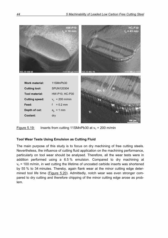
44 5 Machinability of Leaded Low Carbon Free Cutting Steel
HC-P30tc = 43 min
HW-P10tc = 16 min
Work material: 11SMnPb30
Cutting tool: SPUN120304
Tool material: HW-P10, HC-P30
Cutting speed: vc = 200 m/min
Feed: f = 0.2 mm
Depth of cut: ap = 1 mm
Coolant: dryAl
AlMn, S
W
TiTi
Fe
100 μm
HC-P30tc = 43 min
HW-P10tc = 16 min
Work material: 11SMnPb30
Cutting tool: SPUN120304
Tool material: HW-P10, HC-P30
Cutting speed: vc = 200 m/min
Feed: f = 0.2 mm
Depth of cut: ap = 1 mm
Coolant: dryAl
AlMn, S
W
TiTi
Fe
100 μm100 μm
Figure 5.19: Inserts from cutting 11SMnPb30 at vc = 200 m/min
Tool Wear Tests Using Emulsion as Cutting Fluid
The main purpose of this study is to focus on dry machining of free cutting steels. Nevertheless, the influence of cutting fluid application on the machining performance, particularly on tool wear should be analysed. Therefore, all the wear tests were in addition performed using a 6.5 % emulsion. Compared to dry machining at vc = 100 m/min, in wet cutting the lifetime of uncoated carbide inserts was shortened by 55 % to 34 minutes. Thereby, again flank wear at the minor cutting edge deter-mined tool life time (Figure 5.20). Admittedly, notch wear was even stronger com-pared to dry cutting and therefore chipping of the minor cutting edge arose as prob-lem.

5 Machinability of Leaded Low Carbon Free Cutting Steel 45
0
50
100
150
200
250
300
0 1000 2000 3000 4000 5000 6000 7000Cutting length lc / m
Flan
k w
earV
BB
,C,N
S/ μ
m
HC-P30vc = 200 m/min
HW-P10vc = 100 m/min
HW-P10vc = 200 m/min
Tool material: HW-P10Cutting speed: vc = 100 m/minCutting time: tc = 34 min
Work material: 11SMnPb30 Feed: f = 0.2 mmCoolant: Emulsion Depth of cut: ap = 1 mm
5(10)
10(20)
15(30)
20(40)
25(50)
30(60)
35(70)
0(0)
Cutting time tc / min at vc = 200 m/min (100 m/min)
300 μm0
50
100
150
200
250
300
0 1000 2000 3000 4000 5000 6000 7000Cutting length lc / m
Flan
k w
earV
BB
,C,N
S/ μ
m
HC-P30vc = 200 m/min
HW-P10vc = 100 m/min
HW-P10vc = 200 m/min
Tool material: HW-P10Cutting speed: vc = 100 m/minCutting time: tc = 34 min
Work material: 11SMnPb30 Feed: f = 0.2 mmCoolant: Emulsion Depth of cut: ap = 1 mm
5(10)
10(20)
15(30)
20(40)
25(50)
30(60)
35(70)
0(0)
Cutting time tc / min at vc = 200 m/min (100 m/min)
300 μm
Figure 5.20: Tool wear in cutting under application of emulsion
The measurement of process forces at vc = 100 m/min showed that all force compo-nents decreased in wet cutting – but not to the same extend. The cutting force was reduced by only 3 %, whereas feed (-12 %) and thrust force (-20 %) showed a clearer influence of cutting fluid application. This is also reflected by the calculated force ratio, which decreased from 0.6 to 0.54. Nevertheless, a lubricating advantage of cutting fluid utilisation did not improve the machining performance with regard to tool wear development.
The measurement of surface quality indicated, that the application of cutting fluid contributed to lower surface roughness. This is reflected by the drop of the arithmetic mean value Ra from 4.14 μm to 3.81 μm, which is equal to 8 %. The reduction of sur-face roughness further can be seen in Figure 5.21. The longitudinal sections of parts machined in dry and wet condition clearly illustrate that the roughness peaks are higher in dry cutting.
At elevated cutting speed of vc = 200 m/min also a drop in tool life could be observed while using uncoated carbide inserts. In this case, flank wear at the major cutting edge finalised tool life 31 % earlier than in dry cutting. Comparing the inserts from wet and dry cutting it was obvious, that also at this speed notch wear was stronger when using emulsion. At 200 m/min the measured mechanical tool loads were in ac-cord with tool wear as all force components and also the force ratio rose compared to dry machining
However, the application of coated inserts showed similar results for dry and wet ma-chining. A nearly congruent run of the tool wear curve could be observed for both
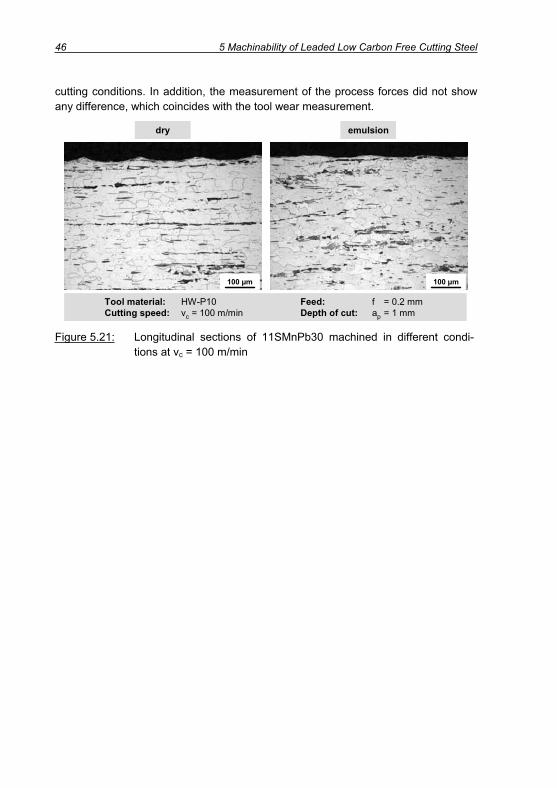
46 5 Machinability of Leaded Low Carbon Free Cutting Steel
cutting conditions. In addition, the measurement of the process forces did not show any difference, which coincides with the tool wear measurement.
Tool material: HW-P10 Feed: f = 0.2 mmCutting speed: vc = 100 m/min Depth of cut: ap = 1 mm
emulsiondry
100 μm100 μm
Tool material: HW-P10 Feed: f = 0.2 mmCutting speed: vc = 100 m/min Depth of cut: ap = 1 mm
emulsiondry
100 μm100 μm100 μm100 μm
Figure 5.21: Longitudinal sections of 11SMnPb30 machined in different condi-tions at vc = 100 m/min

6 Machinability of Different Alloyed Free Cutting Steels 47
6 Machinability of Different Alloyed Free Cutting Steels
Different alloyed materials according to chapter 4 were subject to a multitude of ma-chinability tests. Various testing set-ups were applied in order to give wide informa-tion about the machining performance of the different materials. Thereby, the ma-chinability of leaded steel 11SMnPb30 described in chapters 5.3 and 0 is the basis of comparison. But before the materials are characterised in machining tests, possible substitutes for lead are described and reasons for consideration are given.
6.1 Description of Possible Substitutes for Lead
The six approaches to describe the functions of lead in cutting, which were given in chapter 5.1, partially describe very different effects, but they are not mutually exclu-sive. They rather complement each other and it can be assumed that the function of lead in cutting processes cannot be described with only one of the six approaches. Nevertheless, it becomes clear, that the outstanding properties of lead are the low melting point and the fact, that lead is not soluble in steel and therefore exists as sub microscopic inclusions. Hence, it is fair to assume that also possible substitutions for lead should be characterised by low melting temperatures and insolubility in steel in order to ensure low process forces, high surface quality, desirable chip breakage and few tool wear, particularly in the lower range of cutting speeds. However, the envi-ronmental aspect should not be neglected as lead is under threat only for this reason.
Table 6.1 shows the melting temperatures of different chemical elements, which should be considered regarding the substitution for lead. Obviously, the mentioned elements describe a big range of melting temperatures between 44 and 450°C. Al-though steel grades alloyed with P, Se and Te are not considered in this work, the alloying elements are described because they generally count among alloying ele-ments for machinability enhancement.
Property Pb P S Se Sn Bi Te
Melting point / °C 327 44 118 217 232 271 450
Table 6.1: Melting temperatures of different elements [GROT04]
6.1.1 Phosphorus ( S, P = 44°C)
Adding up to 0.1 % phosphorus (P), which is characterised by the lowest melting temperature of only S, P = 44°C, affects the machinability positively. Particularly, chip breakage and surface quality can be improved due to embrittlement of the ferrite grains [KOEN02, TOEN95]. Although machinability can be enhanced, the mechanical properties of the steel are so much deteriorated that the phosphorus content of high-

48 6 Machinability of Different Alloyed Free Cutting Steels
grade steel must not exceed 0.03 % [ANDE71, WINK83]. Therefore, phosphorus ap-pears not to be an appropriate substitute for lead.
6.1.2 Sulphur ( S, S = 118°C)
Generally, the machinability improving effect of S, particularly MnS, is already pre-sent in low carbon free cutting steels of the 11SMn30 type, as this material shows 0.9 – 1.3 % Mn and 0.27 – 0.33 % S. The further increase of manganese and sulphur content suggests itself, but as already shown limitations are given with respect to the mechanical properties of the work piece particularly orthogonal to the rolling direction [AREN04]. Thus, a steel 11SMn37 with slightly increased sulphur and correspondingly manganese content is investigated within this present research work whereas a fur-ther rise of sulphur content is in focus.
6.1.3 Tellurium and Selenium ( S, Te = 450°C, S, Se = 217°C)
In steel making tellurium (Te) is mainly added in order to influence the shape of man-ganese sulphides and to build manganese telluride. Thus, the machinability enhanc-ing effect of tellurium is mainly combined with the effectiveness of manganese sul-phides in cutting processes. A lot of research work has been done to show the influ-ence of tellurium treatment [ABOR77, ABEY83, BOEH84, FINN90, FLEI85, HUCH93,LESK86]. However, tellurium shows a certain degree of toxicity [TOWN95, WIKI06] and therefore should not be considered more deeply in the present work as it seems not reasonable to substitute one toxic element by another. Similar to the function of tellu-rium, also selenium (Se) is able to modify the shape of non metallic inclusions and to improve machinability [ABOR77, WINK83]. Admittedly, selenium and other elements like arsenic ( S, As = 615°C) and antimony ( S, Sb = 631°C), which show the same in-fluence on sulphide modification, usually come not into operation as a result of toxic-ity [TOWN95]. For this certain reason, also in the present work, the mentioned ele-ments are not taken into deeper consideration.
6.1.4 Tin ( S, Sn = 232°C)
In free cutting steels tin played only a secondary part for a long time. It was regarded as a kind of pest for steels because the grain boundary adhesion is lowered by add-ing tin and the crack intensity at elevated temperatures is heightened [BLAC84,HUCH98]. For this certain reason, the American scientists DEARDO and GARCIA
[DEAR99A, DEAR99B, DEAR01A, DEAR01B, GARC02] suggest the element tin to be the best substitute for lead. At the end of the nineties they developed the so called “green steel 12T14”, which is chemically similar to AISI 12L14 but lead is substituted by 0.04 – 0.08 % Sn. The mentioned scientists investigated again in detail the role of lead in machining and concluded that the predominating effect is liquid metal embrit-tlement (see chapter 5.1) [GARC98]. Tin also shows the LME effect but not the other functions shown for lead in chapter 5.1. Subsequently, the effect of tin in machining

6 Machinability of Different Alloyed Free Cutting Steels 49
can be reduced to the migration of tin to the ferrite gain boundaries and the resulting embrittlement. In cutting, the fracture mode during chip formation changes from in-tergranular fracturing to grain boundary fracturing. However, the tin content should be limited to 0.08 % at maximum since the decrease of toughness as a result of higher tin content would impair the performance characteristics of the material. In addition, also copper plays a significant role in the development of tin alloyed steel. The cop-per concentration should not exceed 0.02 % to prevent it from occupying the precipi-tation sites and impairing the effectiveness of tin. Further, in order to increase the effect of tin, a specific heat treatment of tin added steel prior to machining is sug-gested. A further heat treatment after the cutting operation would pass back the toughness to the steel [BERN01, DEAR99A, DEAR99B, DEAR01A, DEAR01B, GARC02,GRAB89, LAUR99, NAGA97, MINT99].
Apparently, a lot of work was conducted on the material behaviour, but a compre-hensive machinability investigation is not available. Consequently, tin alloyed steel is included in the machinability tests. Thereby, a distinction regarding high and low cop-per content is made.
6.1.5 Bismuth ( S, Bi = 271°C)
The element which shows the strongest physical and chemical similarity to lead is its direct neighbour in the periodic system of the elements, bismuth (Bi). Research work dealing with the effect of bismuth on machinability was firstly published in 1941 [PRAY41]. Thus, the effect of bismuth in machining was discovered when leaded steel was already established on the market. Consequently, alloying with bismuth was not of so much interest in those days. For the first time, 0.3 % bismuth was used as ma-chinability enhancer in 1945, while it served mainly for machinability improvement of leaded steels. The use of bismuth to improve machinability was not developed com-mercially until 1962 when the first leaded standard steel was alloyed with 0.05 – 0.1 % bismuth [ABOR68, GARV66].
Comparable to lead, bismuth is not soluble in steel and it is distributed in sub micro-scopic size as low melting particles with a fusion point of only S, Bi = 271°C without impairing significantly the mechanical and corrosive properties of the steel. As the boiling point of bismuth (1560°C) is in the vicinity of steel pouring temperatures, the loss by volatilisation has to be considered. Further, owing to its low solubility and greater density than that of iron, it tends to segregate towards the bottom of a slowly freezing casting. Nevertheless, bismuth has a lower density than lead and therefore the tendency to segregation is lower [ABOR68, JIAN96].
The machinability improving behaviour of bismuth and lead is similar, although the positive effects of bismuth can be achieved at lower contents [APPL89, AREN04].SOMEKAWA ET AL. [SOME01] led this observance back to enhanced wettability of steel by bismuth compared to lead. They claimed that embrittlement in cutting increases
50 6 Machinability of Different Alloyed Free Cutting Steels
as a result of good wetting properties. Generally, the functions of bismuth in cutting can be summarised as follows:
1. Formation of a lubrication film due to the low melting point S, Bi = 271° [JIAN96].
2. Operating as diffusion barrier [JIAN96].
3. Settlement at MnS and decrease of the sulphide formability [JIAN96].
4. Stress concentration and formation of voids and micro cracks [JIAN96].
5. Stretching of spherical bismuth inclusions and acting as sliding points [AREN04].
6. Embrittlement and crack initiation in the temperature range 300 – 400°C [SOME01,ZASL95].
Compared to leaded steel, fewer investigations have been conducted on bismuth alloyed free cutting steels although good machining performance was acknowledged [BERT95, BERT98, BHAT82, MILO83, YAGU89]. Hence, it seems that bismuth counts among those elements, which have high potential regarding the substitution for lead with regard to machining operations. Nevertheless, it has to be proven in machinabil-ity tests if bismuth is capable of substituting for lead or just capable of improving leaded steel.
6.2 Screening Test
First important results were generated in a screening test similar to the description in chapter 5.2. Same type of uncoated and coated carbide tools and same cutting pa-rameters as in screening 11SMnPb30 were used for different alloyed low carbon free cutting steels according to chapter 4.1 in order to allow for a comparison of the re-sults.
6.2.1 Process Forces
It was already described that normal and tangential forces are useful to describe the tool loads and contribute to an appropriate description of the contact conditions of tool and work material. For this reason the force components Fc, Ff and Fp are not considered individually but they are of course factored in F t and F n.
The left part of Figure 6.1 shows the normal forces F n in turning with uncoated car-bide tools at three feeds. For the various materials, a similar run of the force curves in dependence of the cutting speed was discernible. Accordingly, normal forces de-creased by up to 12 % when increasing the cutting speed from 80 to 300 m/min. At f = 0.4 mm a siginificant rise was not detectable for the non-leaded steels, whereas here the strongest influence of cutting speed on force reduction in the upper cutting speed range was obvious.
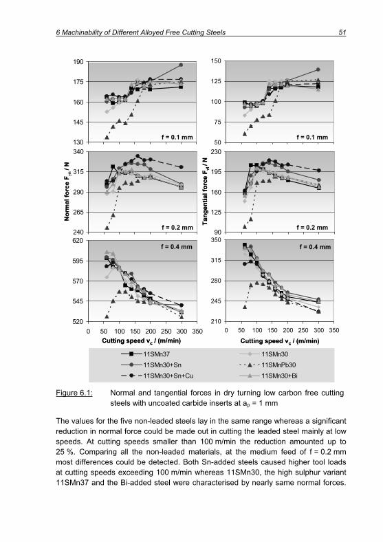
6 Machinability of Different Alloyed Free Cutting Steels 51
Cutting speed vc / (m/min)
240
265
290
315
340
0 50 100 150 200 250 300 350
Nor
mal
forc
e F
n/ N
f = 0.2 mm
Cutting speed vc / (m/min)
520
545
570
595
620
0 50 100 150 200 250 300 350
f = 0.4 mm
130
145
160
175
190
f = 0.1 mm50
75
100
125
150
f = 0.1 mm
Tang
entia
l for
ce F
t/ N
90
125
160
195
230
f = 0.2 mm
210
245
280
315
350
0 50 100 150 200 250 300 350
Cutting speed vc / (m/min)
f = 0.4 mm
11SMn3711SMn30+Sn11SMn30+Sn+Cu
11SMn3011SMnPb3011SMn30+Bi
Cutting speed vc / (m/min)
240
265
290
315
340
0 50 100 150 200 250 300 350
Nor
mal
forc
e F
n/ N
f = 0.2 mm
Cutting speed vc / (m/min)
520
545
570
595
620
0 50 100 150 200 250 300 350
f = 0.4 mm
130
145
160
175
190
f = 0.1 mm50
75
100
125
150
f = 0.1 mm
Tang
entia
l for
ce F
t/ N
90
125
160
195
230
f = 0.2 mm
210
245
280
315
350
0 50 100 150 200 250 300 350
Cutting speed vc / (m/min)
f = 0.4 mm
11SMn3711SMn30+Sn11SMn30+Sn+Cu
11SMn3011SMnPb3011SMn30+Bi
Figure 6.1: Normal and tangential forces in dry turning low carbon free cutting steels with uncoated carbide inserts at ap = 1 mm
The values for the five non-leaded steels lay in the same range whereas a significant reduction in normal force could be made out in cutting the leaded steel mainly at low speeds. At cutting speeds smaller than 100 m/min the reduction amounted up to 25 %. Comparing all the non-leaded materials, at the medium feed of f = 0.2 mm most differences could be detected. Both Sn-added steels caused higher tool loads at cutting speeds exceeding 100 m/min whereas 11SMn30, the high sulphur variant 11SMn37 and the Bi-added steel were characterised by nearly same normal forces.

52 6 Machinability of Different Alloyed Free Cutting Steels
Overall it can be stated, that alloying free cutting steels neither with 0.075 % bismuth nor 0.055 % tin made a positive impact on cutting forces.
Similar to the normal force, also for the tangential force a negative influence of cut-ting speed at low feed and a positive influence at high feed could be detected. Admit-tedly, the weight of the cutting speed influence was for all materials bigger for the tangential force, which confirms the results from chapter 5.3 that feed and thrust force showed strongest cutting speed dependency. This is also reflected by the force ratios depicted in Figure 6.2. Similarly to the force increase also a rise in force ratio was observable. At a feed of f = 0.1 mm this transition lay in the case of lead free steels between vc = 120 and 140 m/min. As already mentioned before, the leaded steel showed higher transition speeds (140 – 180 m/min). Similar to leaded steel, also for the non-leaded materials the change in contact conditions was moved to-wards lower speeds in case of increased feed.
0,3
0,4
0,5
0,6
0,7
0,8
0,3
0,4
0,5
0,6
0,7
0,8
0 50 100 150 200 250 300 350 0 50 100 150 200 250 300 350Cutting speed vc / (m/min) Cutting speed vc / (m/min)
Forc
e ra
tiok
f = 0.1 mm
f = 0.2 mm f = 0.4 mm
Forc
e ra
tiok
11SMn3711SMn30+Sn11SMn30+Sn+Cu11SMn3011SMnPb3011SMn30+Bi
0,3
0,4
0,5
0,6
0,7
0,8
0,3
0,4
0,5
0,6
0,7
0,8
0 50 100 150 200 250 300 350 0 50 100 150 200 250 300 350Cutting speed vc / (m/min) Cutting speed vc / (m/min)
Forc
e ra
tiok
f = 0.1 mm
f = 0.2 mm f = 0.4 mm
Forc
e ra
tiok
11SMn3711SMn30+Sn11SMn30+Sn+Cu11SMn3011SMnPb3011SMn30+Bi
Figure 6.2: Force ratio in dry turning low carbon free cutting steels with un-coated carbide inserts at ap = 1 mm
The tremendous change in contact conditions correlated to a change in chip struc-ture and size. Figure 6.3 illustrates light microscopic views of chips generated just before the force increase (vc = 120 m/min) and after the high level was reached (vc = 140 m/min). The photos originate from cutting 11SMn30+Bi, whereas they serve as example for all the investigated steels.

6 Machinability of Different Alloyed Free Cutting Steels 53
The chips generated at higher cutting speed showed a rise in chip thickness hch or respectively in chip compression ch in accordance with the force increase. In addi-tion, at higher cutting speed the formation of a flow zone at the bottom of the chip was visible.
vc = 120 m/min vc = 140 m/min
Work material: 11SMn30+Bi Feed: f = 0.1 mmTool material: HW-P10 Depth of cut: ap = 1 mmCoolant: dry
100 μm 100 μm
20 μm20 μm
vc = 120 m/min vc = 140 m/min
Work material: 11SMn30+Bi Feed: f = 0.1 mmTool material: HW-P10 Depth of cut: ap = 1 mmCoolant: dry
100 μm 100 μm
20 μm20 μm
Figure 6.3: Thickness and structure of chips before (vc = 120 m/min) and after the change in contact conditions (vc = 140 m/min)
The application of coated inserts led to similar results as already described in chapter 5.3.1. Compared to the use of uncoated carbide tools, both normal and tangential forces increased as a result of the larger edge radius (Figure 6.4). In machining with CVD-coated inserts at f = 0.1 mm the transition speeds, where forces increased are shifted to lower cutting speeds.
Especially at f = 0.1 mm, where lead is supposed to significantly decrease process forces, the influence diminished at cutting speeds exceeding vc = 100 m/min. Using uncoated tools, the respective speed was vc = 180 m/min. Hence, at low feed the effect of lead on process forces in machining with coated tools was lower compared to uncoated inserts.

54 6 Machinability of Different Alloyed Free Cutting Steels
140
155
170
185
200
250
275
300
325
350
Nor
mal
forc
e F
n/ N
f = 0.2 mm
540
565
590
615
640
0 50 100 150 200 250 300 350
Cutting speed vc / (m/min)
f = 0.4 mm
70
95
120
145
170
f = 0.1 mm
100
140
180
220
260
Tang
entia
l for
ce F
t/ N
f = 0.2 mm
260
300
340
380
420
0 50 100 150 200 250 300 350Cutting speed vc / (m/min)
f = 0.4 mm
11SMn3711SMn30+Sn11SMn30+Sn+Cu
11SMn3011SMnPb3011SMn30+Bi
f = 0.1 mm140
155
170
185
200
250
275
300
325
350
Nor
mal
forc
e F
n/ N
f = 0.2 mm
540
565
590
615
640
0 50 100 150 200 250 300 350
Cutting speed vc / (m/min)
f = 0.4 mm
70
95
120
145
170
f = 0.1 mm
100
140
180
220
260
Tang
entia
l for
ce F
t/ N
f = 0.2 mm
260
300
340
380
420
0 50 100 150 200 250 300 350Cutting speed vc / (m/min)
f = 0.4 mm
11SMn3711SMn30+Sn11SMn30+Sn+Cu
11SMn3011SMnPb3011SMn30+Bi
140
155
170
185
200
250
275
300
325
350
Nor
mal
forc
e F
n/ N
f = 0.2 mm
540
565
590
615
640
0 50 100 150 200 250 300 350
Cutting speed vc / (m/min)
f = 0.4 mm
70
95
120
145
170
f = 0.1 mm
100
140
180
220
260
Tang
entia
l for
ce F
t/ N
f = 0.2 mm
260
300
340
380
420
0 50 100 150 200 250 300 350Cutting speed vc / (m/min)
f = 0.4 mm
140
155
170
185
200
250
275
300
325
350
Nor
mal
forc
e F
n/ N
f = 0.2 mm
540
565
590
615
640
0 50 100 150 200 250 300 350
Cutting speed vc / (m/min)
540
565
590
615
640
0 50 100 150 200 250 300 350
Cutting speed vc / (m/min)
f = 0.4 mm
70
95
120
145
170
f = 0.1 mm
100
140
180
220
260
Tang
entia
l for
ce F
t/ N
f = 0.2 mm
260
300
340
380
420
0 50 100 150 200 250 300 350Cutting speed vc / (m/min)
f = 0.4 mm
11SMn3711SMn30+Sn11SMn30+Sn+Cu
11SMn3011SMnPb3011SMn30+Bi
f = 0.1 mm
Figure 6.4: Normal and tangential forces in dry turning low carbon free cutting steels with coated carbide inserts at ap = 1 mm
Using coated carbide tools the influence of lead on the force ratio (Figure 6.5) was also not as obvious as in turning with uncoated tools (Figure 6.2). Regarding the dif-ferent alloyed steels, main differences could be detected at the medium feed f = 0.2 mm. At cutting speeds higher than 140 m/min not the leaded material but the bismuth added and also tin and copper alloyed steels showed the lowest force ratio. However, Figure 6.5 can be used for a comparison of the different materials, but it should not be taken for distinguishing the friction conditions on uncoated and coated

6 Machinability of Different Alloyed Free Cutting Steels 55
tools since the influence of the cutting edge radius on the process forces and hence on the calculation of the force ratio was obvious.
0,4
0,5
0,6
0,7
0,8
0,9
0 50 100 150 200 250 300 3500,4
0,5
0,6
0,7
0,8
0,9
0 50 100 150 200 250 300 350Cutting speed vc / (m/min) Cutting speed vc / (m/min)
Forc
e ra
tiok
f = 0.1 mm
f = 0.2 mm f = 0.4 mm
Forc
e ra
tiok
11SMn3711SMn30+Sn11SMn30+Sn+Cu11SMn3011SMnPb3011SMn30+Bi
0,4
0,5
0,6
0,7
0,8
0,9
0 50 100 150 200 250 300 3500,4
0,5
0,6
0,7
0,8
0,9
0 50 100 150 200 250 300 350Cutting speed vc / (m/min) Cutting speed vc / (m/min)
Forc
e ra
tiok
f = 0.1 mm
f = 0.2 mm f = 0.4 mm
Forc
e ra
tiok
11SMn3711SMn30+Sn11SMn30+Sn+Cu11SMn3011SMnPb3011SMn30+Bi
Figure 6.5: Force ratios in dry turning low carbon free cutting steels with coated carbide inserts (HC-P30) at ap = 1 mm
6.2.2 Specific Cutting Forces
Process force are always strongly depending on the applied cutting conditions. In order to provide a basis for rating the different materials and to allow for the calcula-tions of cutting forces, the specific cutting forces are important. According to KIENZLE
[KIEN52] the correlation between cutting force and uncut chip thickness, correspond-ingly feed can be specified:
)cm1(1.1c
cc hk
bF
F' Equation 6.1
)cm1(1.1cc hbkF Equation 6.2
The specific cutting force kc1.1 represents the cutting force, which is necessary for machining a chip cross section A = h*b = 1 mm*1 mm. F’c is the cutting force related to the width of cut b. The exponent of the Kienzle equation (1-mc) describes the rise of the cutting force F’c as a function of uncut chip thickness h. It is the slope of F’c in the double logarithmic scale.

56 6 Machinability of Different Alloyed Free Cutting Steels
100 200 300
Spec
. For
ce k
c1.1
/ (N
/mm
2 )
1000
1100
1200
1300
1400
1500
1600
100 200 300
Cutting Tool: SPUN120304 Depth of cut: ap = 1 mmTool material: HW-P10, HC-P25 Coolant: dry
11SM
n37
11SM
n30+
Sn+C
u11
SMn3
0+Sn
+Cu
11SM
n30
11SM
n30+
Bi
11SM
n30+
Sn
11SM
nPb3
0
0,50
0,60
0,70
0,80
0,90
1,00
100 200 300 100 200 300
Gra
dien
t (1-
mc)
HC-P30HW-P10
HC-P30HW-P10
Cutting speed vc / (m/min) Cutting speed vc / (m/min)
100 200 300
Spec
. For
ce k
c1.1
/ (N
/mm
2 )
1000
1100
1200
1300
1400
1500
1600
100 200 300
Cutting Tool: SPUN120304 Depth of cut: ap = 1 mmTool material: HW-P10, HC-P25 Coolant: dry
11SM
n37
11SM
n30+
Sn+C
u11
SMn3
0+Sn
+Cu
11SM
n30
11SM
n30+
Bi
11SM
n30+
Sn
11SM
nPb3
0
0,50
0,60
0,70
0,80
0,90
1,00
100 200 300 100 200 300
Gra
dien
t (1-
mc)
HC-P30HW-P10
HC-P30HW-P10
Cutting speed vc / (m/min) Cutting speed vc / (m/min)
Figure 6.6: Characteristic parameters kc1.1 and (1-mc) of free cutting steels
In order to consider the strong influence of cutting speed on the cutting forces, the characteristic parameters were calculated and illustrated for three different cutting speeds (Figure 6.6) and two cutting materials. The rise of cutting velocity led to a tremendous decrease of specific cutting forces kc1.1 by partly more than 20 % for all materials which is caused by several mechanisms described in chapter 7.
Considering the whole range of cutting speeds and both cutting materials, only slight differences in the values kc1.1 and (1-mc) for the various materials were obvious. Comparing the maximal and minimal specific cutting forces with a mean value for all the materials, deviations of less than 5 % could be detected. This is quite few as kc1.1
is an extrapolated value and the exactness of the extrapolation rises with a higher number of investigated feeds. Previous investigations [KOEN82] showed values of kc1.1 = 1390 N/mm2 and (1-mc) = 0,82 for a free cutting steel 9SMnPb28, which is chemically similar to 11SMnPb30. Apparently, these values fit into a cutting speed range of vc = 120 – 150 m/min according to the calculations represented in Figure 6.6. At low speed, particularly the extremely high (1-mc) value of 0.96 for 11SMnPb30 should be emphasised, which is caused by the extremely low cutting forces at low feeds.
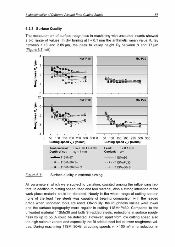
6 Machinability of Different Alloyed Free Cutting Steels 57
6.2.3 Surface Quality
The measurement of surface roughness in machining with uncoated inserts showed a big range of values. In dry turning at f = 0.1 mm the arithmetic mean value Ra lay between 1.13 and 2.85 μm, the peak to valley height Rz between 8 and 17 μm (Figure 6.7, left).
0
1
2
3
4
4
8
12
16
20
0 50 100 150 200 250 300 350 0 50 100 150 200 250 300 350
Rou
ghne
ssR
a/ μ
m
HW-P10 HC-P30
Rou
ghne
ssR
z/ μ
m
HW-P10 HC-P30
Cutting speed vc / (m/min) Cutting speed vc / (m/min)
Tool material: HW-P10; HC-P30 Feed: f = 0.1 mmDepth of cut: ap = 1 mm Coolant: dry
11SMn3711SMn30+Sn11SMn30+Sn+Cu
11SMn3011SMnPb3011SMn30+Bi
Tool material: HW-P10; HC-P30 Feed: f = 0.1 mmDepth of cut: ap = 1 mm Coolant: dry
11SMn3711SMn30+Sn11SMn30+Sn+Cu
11SMn3011SMnPb3011SMn30+Bi
Figure 6.7: Surface quality in external turning
All parameters, which were subject to variation, counted among the influencing fac-tors. In addition to cutting speed, feed and tool material, also a strong influence of the work piece material could be detected. Nearly in the whole range of cutting speeds none of the lead free steels was capable of bearing comparison with the leaded grade when uncoated tools are used. Obviously, the roughness values were lower and the surface topography more regular in cutting 11SMnPb30. Compared to the unleaded material 11SMn30 and both Sn-added steels, reductions in surface rough-ness by up to 55 % could be detected. However, apart from low cutting speed also the high sulphur variant and especially the Bi added steel led to lower roughness val-ues. During machining 11SMn30+Bi at cutting speeds vc > 100 m/min a reduction in

58 6 Machinability of Different Alloyed Free Cutting Steels
surface roughness by up to 31 % compared to 11SMn30 and the Sn added steels could be achieved. In the range of vc = 100 – 150 m/min even the best surface quali-ties of all materials were measured. Considering the whole range of cutting speeds, the leaded steel was superior to all the other materials with regard to surface quality in cutting with uncoated carbide tools at f = 0.1 mm, but alloying with bismuth was the best alternative. Finally, the right part of Figure 6.8 illustrates the tendency that more regular surfaces could be produced at high speed. This correlates very well with the procedures observed for 11SMnPb30 (Figure 5.10).
vc = 200 m/min
vc = 100 m/min
Work material: 11SMn30+Bi Depth of cut: ap = 1 mmFeed: f = 0.1 mm Coolant: dry
HC-P30HW-P10
vc = 200 m/min
vc = 100 m/min
200 μm 200 μm
200 μm 200 μm
vc = 200 m/min
vc = 100 m/min
Work material: 11SMn30+Bi Depth of cut: ap = 1 mmFeed: f = 0.1 mm Coolant: dry
HC-P30HW-P10
vc = 200 m/min
vc = 100 m/min
200 μm 200 μm
200 μm 200 μm
Figure 6.8: Surface topography in dependence of the cutting speed and the tool material in dry turning of 11SMn30+Bi
A rise of the cutting speed tended for all investigated materials to result in an im-provement of surface quality. In addition to the positive influence of cutting speed, also the change to coated tools led to an improvement in surface quality (Figure 6.7 and Figure 6.8, right). The arithmetic mean value lay in a smaller range of Ra = 1.12 – 1.73 μm, thus both the influence of work piece material and of cutting speed became less important for the arithmetic mean value when coated inserts

6 Machinability of Different Alloyed Free Cutting Steels 59
were applied. Admittedly, the peak to valley height Rz showed strong dependence on the cutting speed in the range vc = 60 – 150 m/min.
Nevertheless, in the whole range of cutting speeds for all materials except 11SMnPb30 both Ra and Rz values were significantly lower in cutting with coated tools than in machining with uncoated inserts. The application of coated carbide tools resulted clearly in shrinkage of the predominance of leaded steel. Obviously, the amendment of surface quality due to the deployment of coated inserts was most im-portant for the Sn-added steels, where Ra values dropped by up to 50 %. The surface topography became conspicuously more regular when the speed was increased from 100 to 200 m/min, illustrated in Figure 6.9.
vc = 100 m/min
HC-P30HW-P10
vc = 100 m/min
Work material: 11SMn30+Sn Feed: f = 0.1 mmCutting speed: vc = 200 m/min Depth of cut: ap = 1 mmCoolant: dry
40 μm40 μm
vc = 100 m/min
HC-P30HW-P10
vc = 100 m/min
Work material: 11SMn30+Sn Feed: f = 0.1 mmCutting speed: vc = 200 m/min Depth of cut: ap = 1 mmCoolant: dry
40 μm40 μm
Figure 6.9: Reduction of surface roughness due to the application of coated in-serts in machining of 11SMn30+Sn
The leaded steel showed better surface quality at low cutting speed when using coated tools, at higher cutting speeds a difference between the results from machin-ing with coated or uncoated tools was hardly detectable. However, when coated cut-ting inserts were applied the superior behaviour of 11SMnPb30 diminished and the roughness values for all the material lay in the same range.
The increase of feed resulted in lower surface quality as the kinematical contact con-ditions changed with increasing feed. Accordingly, in the test with uncoated inserts the arithmetic mean value was measured with Ra = 3.08 – 5.15 μm and the peak to valley height with Rz = 16.84 – 26.87 μm (Figure 6.10, left). At cutting speed vc = 60 m/min, an improvement in surface quality could be detected for 11SMn37. Between 100 and 300 m/min the run of the surface roughness curves was similar for all materials but the level was different. Thereby, 11SMn37 and 11SMn30+Bi at cut-ting speeds vc > 140 m/min showed the best surface quality. The tendency, that out

60 6 Machinability of Different Alloyed Free Cutting Steels
of the unleaded steels the high S and the Bi added variant performed best in terms of surface quality was similar to the results obtained at low feed. Admittedly, the surface quality improvement due to alloying with Pb could not be seen at elevated feed. Compared to lead, the addition of alternative alloying elements showed higher poten-tial regarding surface finish at a feed of f = 0.2 mm.
0 50 100 150 200 250 300 350
0
1,5
3
4,5
6HW-P10 HC-P30
Rou
ghne
ssR
a/ μ
m
10
15
20
25
30
0 50 100 150 200 250 300 350
Rou
ghne
ssR
z/ μ
m
Cutting speed vc / (m/min) Cutting speed vc / (m/min)
HW-P10 HC-P30
Tool material: HW-P10; HC-P30 Feed: f = 0.2 mmDepth of cut: ap = 1 mm Coolant: dry
11SMn3711SMn30+Sn11SMn30+Sn+Cu
11SMn3011SMnPb3011SMn30+Bi
0 50 100 150 200 250 300 350
0
1,5
3
4,5
6HW-P10 HC-P30
Rou
ghne
ssR
a/ μ
m
10
15
20
25
30
0 50 100 150 200 250 300 350
Rou
ghne
ssR
z/ μ
m
Cutting speed vc / (m/min) Cutting speed vc / (m/min)
HW-P10 HC-P30
Tool material: HW-P10; HC-P30 Feed: f = 0.2 mmDepth of cut: ap = 1 mm Coolant: dry
11SMn3711SMn30+Sn11SMn30+Sn+Cu
11SMn3011SMnPb3011SMn30+Bi
Tool material: HW-P10; HC-P30 Feed: f = 0.2 mmDepth of cut: ap = 1 mm Coolant: dry
11SMn3711SMn30+Sn11SMn30+Sn+Cu
11SMn3011SMnPb3011SMn30+Bi
Figure 6.10: Surface quality in external turning at f = 0.2 mm
This potential was particularly obvious when coated tools were deployed (Figure 6.10, right). Nearly in the whole range of applied cutting speeds plain 11SMn30, the Sn+Cu variant and the Bi added steel allowed for the best surface roughness values. Thus, at medium feed and any cutting speed 11SMnPb30 can be displaced by the mentioned steels without taking a loss regarding surface quality.
6.2.4 Chip Formation Process
Beneath the quick stop set-up described in chapter 5.3.3, a set-up for the in-situ pho-tography of the cutting process came into operation. HOPPE introduced this set-up in

6 Machinability of Different Alloyed Free Cutting Steels 61
order to obtain knowledge about segmented chip formation at extremely high cutting speeds [HOPP04]. In continuous chip formation the possibility to analyse chip thick-ness, chip curvature and chip velocity during cutting counts among the advantages.
Work pieceTool
Microscopewith camera
Chuck
Work material: 11SMn30+Bi
Cutting tool: N151.2-540-40-4
Tool material: HW-K10
Cutting speed: vc = 100 m/min
Feed: f = 0.1 mm
Depth of cut: ap= 1 mm
Coolant: dry
t0
t1 = to+ 120 μs
Workpiece
Tool
300 μm
Work pieceTool
Microscopewith camera
Chuck
Work material: 11SMn30+Bi
Cutting tool: N151.2-540-40-4
Tool material: HW-K10
Cutting speed: vc = 100 m/min
Feed: f = 0.1 mm
Depth of cut: ap= 1 mm
Coolant: dry
t0
t1 = to+ 120 μs
Workpiece
Tool
300 μm
Figure 6.11: In-situ photography of an orthogonal turning process
The present investigations were conducted using a set-up, where the work piece ma-terial was fixed and the tool holder was mounted in the chuck of a lathe. Using a mi-croscope with a possible magnification up to 500, two flash lamps with an illumination time of ts = 20 ns and a digital camera designed for double exposure with a minimum time difference of 3 μs [HOPP04], an orthogonal machining process with uncoated carbide tools in a dry cut at vc = 100 and 200 m/min and f = 0.1 mm could be moni-tored. Figure 6.11 shows the experimental set-up and as an example two images of a cutting process, which were taken with a time difference of 120 μs in machining the Bi alloyed steel at vc = 100 m/min. Considering the movement of particular parts of the chip (white box), the chip velocity can be made out.
Comparing the different alloyed materials by means of in-situ photography it could be determined that leaded steel showed the biggest chip curvature. Out of the non-leaded steels, the Bi as well as the high S variant were characterised by strongest chip bending. As a consequence of strong chip curl, on the one hand strain at the bottom side of the chips increase, which is generally beneficial with regard to chip breakage. On the other hand, the chip is likely to impinge on the work piece or on the flank of the tool. The work piece acts as an obstacle and inhibits the free flow of the

62 6 Machinability of Different Alloyed Free Cutting Steels
chip. Since in the continuous cut the chip is steadily formed, material pushes from the newly generated part of the chip. Pushing by the new chip material on one hand and bearing against the work piece on the other hand result in bending up the chip. This is intimately connected with excessive stresses in the chip material, which results in desirable chip breakage [SPAA71, TOEN95]. In contrast to the described procedure, 11SMn30 was characterised by more or less free chip flow (Figure 6.12).
Cutting tool: N151.2-540-40-4 Depth of cut: ap = 1 mmFeed: f = 0.1 mm Coolant: dry
11SMn3011SMnPb30
vc = 200 m/min
vc = 100 m/min
vc= 200 m/min
vc = 100 m/min
300 μm
Cutting tool: N151.2-540-40-4 Depth of cut: ap = 1 mmFeed: f = 0.1 mm Coolant: dry
11SMn3011SMnPb30
vc = 200 m/min
vc = 100 m/min
vc= 200 m/min
vc = 100 m/min
Cutting tool: N151.2-540-40-4 Depth of cut: ap = 1 mmFeed: f = 0.1 mm Coolant: dry
11SMn3011SMnPb30
vc = 200 m/min
vc = 100 m/min
vc= 200 m/min
vc = 100 m/min
300 μm300 μm
Figure 6.12: Different chip curvature in dependence of the work material
Similar to chip curl, also the chip thickness was lowest in machining 11SMnPb30 and again 11SMn30+Bi came next. Admittedly, at vc = 100 m/min all thicknesses lay in a range of hch = 0.16 – 0.19 mm. The increase of cutting speed let for all steels to a reduced chip thickness of hch = 0.12 – 0.17 mm. Contrary, chip velocity increased as a result of cutting speed enlargement, which could be obeserved by the photos gen-erated within a time difference of 120 μs. Hence, the chips generated in machining 11SMnPb30 and 11SMn30+Bi slid with higher speed and therefore more easily on the rake of the cutting tool.
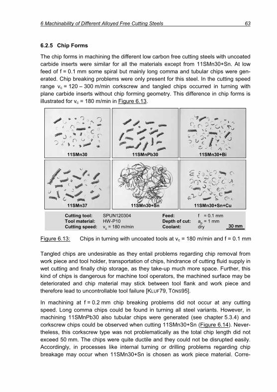
6 Machinability of Different Alloyed Free Cutting Steels 63
6.2.5 Chip Forms
The chip forms in machining the different low carbon free cutting steels with uncoated carbide inserts were similar for all the materials except from 11SMn30+Sn. At low feed of f = 0.1 mm some spiral but mainly long comma and tubular chips were gen-erated. Chip breaking problems were only present for this steel. In the cutting speed range vc = 120 – 300 m/min corkscrew and tangled chips occurred in turning with plane carbide inserts without chip forming geometry. This difference in chip forms is illustrated for vc = 180 m/min in Figure 6.13.
11SMn30+Bi
11SMn30+Sn+Cu
11SMn30
11SMn37
11SMnPb30
11SMn30+Sn
Cutting tool: SPUN120304 Feed: f = 0.1 mmTool material: HW-P10 Depth of cut: ap = 1 mmCutting speed: vc = 180 m/min Coolant: dry 30 mm
11SMn30+Bi
11SMn30+Sn+Cu
11SMn30
11SMn37
11SMnPb30
11SMn30+Sn
Cutting tool: SPUN120304 Feed: f = 0.1 mmTool material: HW-P10 Depth of cut: ap = 1 mmCutting speed: vc = 180 m/min Coolant: dry 30 mm30 mm
Figure 6.13: Chips in turning with uncoated tools at vc = 180 m/min and f = 0.1 mm
Tangled chips are undesirable as they entail problems regarding chip removal from work piece and tool holder, transportation of chips, hindrance of cutting fluid supply in wet cutting and finally chip storage, as they take-up much more space. Further, this kind of chips is dangerous for machine tool operators, the machined surface may be deteriorated and chip material may stick between tool flank and work piece and therefore lead to uncontrollable tool failure [KLUF79, TÖNS95].
In machining at f = 0.2 mm chip breaking problems did not occur at any cutting speed. Long comma chips could be found in turning all steel variants. However, in machining 11SMnPb30 also tubular chips were generated (see chapter 5.3.4) and corkscrew chips could be observed when cutting 11SMn30+Sn (Figure 6.14). Never-theless, this corkscrew type was not problematically as the total chip length did not exceed 50 mm. The chips were quite ductile and they could not be disrupted easily. Accordingly, in processes like internal turning or drilling problems regarding chip breakage may occur when 11SMn30+Sn is chosen as work piece material. Corre-

64 6 Machinability of Different Alloyed Free Cutting Steels
sponding to the trials using the in-situ photography set-up, again stronger bending of leaded chips and lower chip thickness could be observed. For this reason, the chips appeared smaller although the photos in Figure 6.14 were taken with the same mag-nification. A further increase of the feed to f = 0.4 mm resulted for all materials in long comma chips and spiral chips in the whole range of cutting speeds.
11SMn30+Bi
11SMn30+Sn+Cu
11SMn30
11SMn37
11SMnPb30
11SMn30+Sn
Cutting tool: SPUN120304 Feed: f = 0.2 mmTool material: HW-P10 Depth of cut: ap = 1 mmCutting speed: vc = 140 m/min Coolant: dry 30 mm
11SMn30+Bi
11SMn30+Sn+Cu
11SMn30
11SMn37
11SMnPb30
11SMn30+Sn
Cutting tool: SPUN120304 Feed: f = 0.2 mmTool material: HW-P10 Depth of cut: ap = 1 mmCutting speed: vc = 140 m/min Coolant: dry 30 mm30 mm
Figure 6.14: Short breaking chips in turning at f = 0.2 mm with uncoated inserts
The chip forms in turning with CVD-coated inserts were particularly at low feed differ-ent from those generated in cutting with uncoated tools. At low feed up to speeds vc = 100 m/min tubular and long comma chips could be observed. Afterwards a tran-sition to formation of tangled chips could be noticed when the cutting speed rose. At 120 m/min the Sn-steel, at 140 m/min 11SMn37 and at 160 m/min the (Sn+Cu)-variant started to show tangled chips. Also the Bi added steel was characterised by this undesirable chip type at cutting speeds exceeding 140 m/min but only 50 % of the machined material was converted into tangled chips and the other 50 % into fa-vourable long comma chips.
The formation of long, tangled chips could be avoided by the application of higher feed. Mainly long comma chips appeared at f = 0.2 mm. Both Sn-steels and the high sulphur variant also showed some non-critical corkscrew chips and at cutting speeds below 100 m/min 11SMn30, the leaded and Bi-added variants tended to form short tubular chips. Similar to the application of uncoated tools at f = 0.4 mm chip breaking problems did not occur at all and only long comma chips could be observed.

6 Machinability of Different Alloyed Free Cutting Steels 65
Chip forms in turning D = 80 mm material
The chip forms in screening the different free cutting steels of D = 19 mm with un-coated carbide tools did not show big differences apart from the observation that 11SMn30+Sn generated unfavourable tangled chips at low feed. Generally, all steels tended to produce short breaking chips. The 19 mm material was machined in a cold drawn state, which means, that the rim zone was cold formed and therefore the ma-terial showed increased strength and reduced elasticity values. The decreased toughness supports chip breakage.
In order to gain more information about the material behaviour with regard to chip breakage and to provide conditions where differences could be detected, also the material of diameter 80 mm described in chapter 4.1 was used for additional screen-ing tests. This material was delivered in rolled condition and showed lower hardness, lower tensile and especially lower yield strength as well as higher values for elonga-tion at break and reduction of area. Hence, owing to increased ductility and larger bar diameter it could be assumed that chip breakage would be a bigger problem.
Cutting tool: SPUN120304 Feed: f = 0.1 mmTool material: HW-P10 Depth of cut: ap = 2 mmCutting speed: vc = 100 m/min Coolant: dry 50 mm
11SMn30+Bi
11SMn30+Sn+Cu
11SMn30
11SMn37
11SMnPb30
11SMn30+Sn
Cutting tool: SPUN120304 Feed: f = 0.1 mmTool material: HW-P10 Depth of cut: ap = 2 mmCutting speed: vc = 100 m/min Coolant: dry 50 mm
11SMn30+Bi
11SMn30+Sn+Cu
11SMn30
11SMn37
11SMnPb30
11SMn30+Sn
Figure 6.15: Chips from turning 80 mm material with uncoated inserts (HW-P10)
Cutting speeds of vc = 50, 100, 200 and 300 m/min were applied at feeds of f = 0.1, 0.25 and 0.4 mm and a depth of cut ap = 2 mm using uncoated carbide inserts. At vc = 50 m/min tubular, spiral and long comma chips appeared. The longest chips were observed in machining 11SMnPb30 where the tubular chips did not break at all and therefore the chip length only depended on the work piece dimensions. This ex-treme observation was only valid for 50 m/min as in cutting at 100 m/min the chips were shorter. Admittedly, Figure 6.15 proves that the tubular chips still reached a

66 6 Machinability of Different Alloyed Free Cutting Steels
considerable length. However, as this kind of chips is well controllable and does not cause trouble regarding handling, transportation, surface quality or worker’s safety as chip curling is quite strong and the chips are well controllable. The tangled and ribbon chips respectively in turning the Sn-added steel have to be judged worth. In addition, usually short cutting lengths characterise the production of parts from free cutting steel and therefore the tubular chip type is not too critical. When increasing the cut-ting speed to 200 m/min similar undesired chip forms as for 11SMn30+Sn could also be observed for 11SMn30 and the Sn+Cu variant. Finally, at 300 m/min only the Pb- and Bi-added free cutting steels showed short breaking chips (Figure 6.16). The short chip sections in the bottom row of Figure 6.16 appeared be-cause long chips curled around tool holder and work piece. Sometimes the amount of chip material was too high and the ribbon chips were torn apart.
At higher feeds of 0.25 and 0.4 mm chip breaking problems did not occur for any ma-terial over the whole range of cutting speeds and mainly short comma and spiral chips were produced. As already seen in cutting the material of smaller dimension, 11SMn30+Sn and 11SMn37 generated some non critical corkscrew chips with chip lengths up to 50 mm.
Summarising, the results confirm the observations from cutting the 19 mm material whereby the superior behaviour of 11SMnPb30 and the Bi-added variant became more obvious. Particularly at higher cutting speeds and low feeds, thus at finishing conditions, these two materials are preferable with regard to chip breakage.
Cutting tool: SPUN120304 Feed: f = 0.1 mmTool material: HW-P10 Depth of cut: ap = 2 mmCutting speed: vc = 300 m/min Coolant: dry 50 mm
11SMn30+Bi
11SMn30+Sn+Cu
11SMn30
11SMn37
11SMnPb30
11SMn30+Sn
Cutting tool: SPUN120304 Feed: f = 0.1 mmTool material: HW-P10 Depth of cut: ap = 2 mmCutting speed: vc = 300 m/min Coolant: dry 50 mm50 mm
11SMn30+Bi
11SMn30+Sn+Cu
11SMn30
11SMn37
11SMnPb30
11SMn30+Sn
Figure 6.16: Shortest chips in cutting leaded and Bi-added steels

6 Machinability of Different Alloyed Free Cutting Steels 67
6.3 Tool Wear Test
Similar tool wear tests compared to chapter 0 were performed on all different free cutting steels. As already seen for 11SMnPb30, also for the alternative steels tool life was determined by flank wear at the minor cutting edge when applying uncoated car-bide inserts at vc = 100 m/min. Only few flank wear at the major flank could be ob-served. Out of the non leaded steels 11SMn37 showed the lowest value with VBB = 115 μm, in contrast most major flank wear was measured in machining Sn-added steel (VBB = 140 μm). Additionally, in cutting 11SMn30+Sn at the major flank the formation of an enormous notch could be observed (Figure 6.17, left) which reached at the end of the machining tests a value of about 500 μm. Such a wear pat-tern has to be judged very critically as stress concentrates in the notch and therefore cracks might spread through the cemented carbide insert and lead to sudden tool failure.
11SMn30+Bitc = 46 min
11SMn30+Sntc = 65 min
Tool material: HW-P10 Feed: f = 0.2 mmCutting speed: vc = 100 m/min Depth of cut: ap = 1 mmCoolant: dry
300 μm300 μm
11SMn30+Bitc = 46 min
11SMn30+Sntc = 65 min
Tool material: HW-P10 Feed: f = 0.2 mmCutting speed: vc = 100 m/min Depth of cut: ap = 1 mmCoolant: dry
300 μm300 μm
Figure 6.17: Cemented carbide inserts after dry turning at vc = 100 m/min
Taking the tool wear plots in Figure 6.18 into account, it can be stated that tool life was quite long with up to 80 min at best and 46 minutes at least. Best results could be achieved in machining 11SMn37 and 11SMnPb30. In cutting leaded steel flank wear at the minor cutting edge reached the tool life criterion of VB = 250 μm about 4 minutes earlier compared to 11SMn37, but flank wear at the major cutting edge was measured with 20 % lower values. Consequently, 11SMn37 can be regarded as best choice comparing the different alloyed non-leaded materials with 11SMnPb30 for external turning with uncoated carbide inserts at vc = 100 m/min in dry condition. Compared to a plain non-leaded 11SMn30 tool life improvement by 38 % could be achieved.

68 6 Machinability of Different Alloyed Free Cutting Steels
0
50
100
150
200
250
300
0 1000 2000 3000 4000 5000 6000 7000 8000 9000
11SMn3011SMnPb3011SMn30+Bi
Cutting length lc / m
Flan
k w
earV
BB
,C,N
S/ μ
m
10 20 30 40 50 60 700 9080
Work material: 11SMnPb30
Tool material: HW-P10
Cutting speed: vc = 100 m/min
Feed: f = 0.2 mm
Depth of cut: ap = 1 mm
Coolant: dry11SMn3711SMn30+Sn11SMn30+Sn+Cu
Cutting time tc / min
Figure 6.18: Flank wear in dependence of cutting length and cutting time
As before stated the shortest cutting length had to be observed in machining the Bi added steel. Analysing chip roots, it could be made out that build up edge formation was stronger compared to other materials. The left image in depicts a chip root from cutting 11SMn30+Bi at 100 m/min. The machined surface area of the work piece shows the scaly topography which is characteristically for build up edge formation. As the chip bottom side does not show such a strong influence of build up edge forma-tion, it can be concluded, that mainly the flank and work piece surface were affected. However, in the area of the nose radius, the surface quality of the chip is more irregu-lar compared to the remaining bottom side. In Figure 6.19 the high magnification in the right image illustrates white carbide particles (1) originated from tool material which stick to the bottom side of the build up edge. The image shows that not only chip material adhered to the cutting tool but also material from the work piece side. The top part (2) was torn out of the work piece surface (3) and moved with the tool in cutting direction. Hence, both work piece and build up edge showed a similar run of the parting line (4).
The strong difference in tool wear was mainly visible in the area of minor cutting edge and nose radius. At the major cutting edge flank wear of only 119 μm was detected in cutting 11SMn30+Bi, which lay in the same range compared to 11SMn30 and both Sn-grades at similar cutting lengths. Further, the wear pattern at the cutting insert used for turning 11SMn30+Bi appeared quite uniform (Figure 6.17, right) and the notch formed at the minor cutting edge was not as deep as in machining all the other materials. This is an advantage of the Bi added steel since sudden tool failure be-comes improbable although shortest cutting time was reached.

6 Machinability of Different Alloyed Free Cutting Steels 69
Work material: 11SMn30+Bi Feed: f = 0.2 mmTool material: HW-P10 Depth of cut: ap = 1 mmCutting speed: vc = 100 m/min Coolant: dry
2
3
4
1
20 μm400 μm
Work material: 11SMn30+Bi Feed: f = 0.2 mmTool material: HW-P10 Depth of cut: ap = 1 mmCutting speed: vc = 100 m/min Coolant: dry
2
3
4
1
20 μm20 μm400 μm
Figure 6.19: Flank wear in dependence of cutting length and cutting time
The increase of cutting speed to 200 m/min resulted in a change of tool wear pattern as already observed in machining 11SMnPb30. Extensive flank wear occurred at the major rather than minor flank (Figure 6.20, left). In addition, crater wear on the rake was heightened, which can be shown by the SE image in the right part of Figure 6.20. Thereby, the crater front distance was larger compared to machining 11SMnPb30, which is beneficial for the stability of the cutting edge.
Work material: 11SMn30 Feed: f = 0.2 mmTool material: HW-P30 Depth of cut: ap = 1 mmCutting speed: vc = 200 m/min Coolant: dry
300 μm300 μm
Work material: 11SMn30 Feed: f = 0.2 mmTool material: HW-P30 Depth of cut: ap = 1 mmCutting speed: vc = 200 m/min Coolant: dry
300 μm300 μm
Figure 6.20: Tool after machining at vc = 200 m/min for tc = 11 min
In order to quantify the influence of cutting speed increase, the cutting temperatures were measured using a two-colour pyrometer FIRE-1 developed by the Institute of Heat and Mass Transfer (WSA, former WÜK) at RWTH Aachen. The applicability of this device for cutting operations was shown in miscellaneous studies [MUEL02,

70 6 Machinability of Different Alloyed Free Cutting Steels
MUEL04, MUEL03, HOPP04, KRIE00, SUTT03]. The two-colour pyrometer is based on the physical principle of heat radiation measurement [MUEL01]. Figure 6.21 shows a schematic view of the two-colour pyrometer. The infrared radiation which is emitted from the object surface is collected and transmitted to the pyrometer housing by a quartz fibre. The fibre is flexible and protected by a polyimide coating. The radiation is focussed by a lens and a dichroic beam splitter leads the radiation to two detec-tors. The diodes are sensitive at wavelengths of l = 1.7 μm and l = 2.0 μm. The sig-nals are amplified and filtered, before they are evaluated. The deployed pyrometer has a very high time resolution of t = 2 μs and allows to measure temperatures down to 250 °C [HOPP04].
Figure 6.21: Principle of the two-colour pyrometer [MUEL01]
The focus of the measurements was on the bottom side of the chip as it was the aim to measure the maximum temperatures in the cutting process, which occur in this area [VIER70]. Therefore, the fiber (D = 0.5 μm) was mounted in a hole manufactured in the uncoated carbide insert by electro discharge machining (EDM). An overview of the experimental set-up is given in Figure 6.22.
At a cutting speed of vc = 100 m/min (ap = 1 mm, f = 0.2 mm) the temperature at the bottom of the chip was measured for all the materials in a range of 525 – 550°C, where 11SMn30+Bi generated highest temperatures. According to various re-searches [BART88, VIER55A, VIER55B, KOEN02, DAM90] maximum temperatures occur in the centre of the contact zone. Since the fibre was located in a distance of 0.35 mm from the major cutting edge and the contact length amounted around 0.65 mm, the temperature at the bottom side of the chip just at the end of the contact zone was measured. It can be concluded that this is close to the highest temperature in the contact zone although it is not the maximum value. The temperatures on the rake are decisive for crater wear, but they also allow for a conclusion regarding the thermal load at the flank since isotherms can be found in the cutting wedge [BART88,DAMA90, KOEN02, VIER55A, VIER55B], see Figure 6.22. As these isotherms proceed from rake to flank, it can be assumed that temperatures similar to those measured on the rake arose also at the major flank of the cutting insert.

6 Machinability of Different Alloyed Free Cutting Steels 71
0.35 mm
0.35
mm
Insert
Clamping
Dynamometer
Quartz fibre
Electronics
Optics, Detectors, Amplifiers
Data acquisition
HW-P10
Insert
Work piece
Chip
Quartz fibreQuartz fibre
12
0.35 mm
0.35
mm
Insert
Clamping
Dynamometer
Quartz fibre
Electronics
Optics, Detectors, Amplifiers
Data acquisition
HW-P10
Insert
Work piece
Chip
Quartz fibreQuartz fibre
12
Figure 6.22: Testing set-up for temperature measurement with two-colour pyrometer
The change of cutting speed from 100 to 200 m/min entailed a strong increase in temperature up to a level of 620 – 675°C. Since the contact zone on the rake de-creased when the cutting speed was heightened, the distance of the measuring point to the location of highest temperature rose. Thus, it can be concluded that the tem-peratures increased by at least 20 %.
According to Figure 6.23 11SMn30 and the Sn added steels reached tool life times of 10 to 11 minutes, which corresponds to an unwound cutting length of 2,000 – 2,200 m. 11SMn37 and 11SMn30+Bi allowed for a life time of 13 minutes (2,600 m) and the leaded variant was characterised by the longest tool life with 16 minutes (3,200 m). In accordance with the wear behaviour of the different steels, the analysis of chip roots also showed differences. Those steels, which caused most tool wear showed biggest amounts of carbide particles sticking to the chip root.

72 6 Machinability of Different Alloyed Free Cutting Steels
0 1500 3000 4500 6000 7500 90000
50
100
150
200
250
300
0 750 1500 2250 3000 3750 4500
Cutting length lc / m
Flan
k w
earV
BB
,C,N
S/ μ
m
Cutting length lc / m
Cutting time tc / min3.75 7.5 11.25 15 18.750 22.5 7.5 15 22.5 30 37.50 45
Cutting time tc / min
Cutting speed: vc = 200 m/min Feed: f = 0.2 mmCoolant: dry Depth of cut: ap = 1 mm
HW-P10 HC-P30
11SMn3011SMnPb3011SMn30+Bi
11SMn3711SMn30+Sn11SMn30+Sn+Cu
Figure 6.23: Flank wear progression in dry machining at vc = 200 m/min with un-coated (HW-P10) and TiCN/Al2O3/TiN-coated (HC-P30) inserts
Compared to the results from turning at vc = 100 m/min up to 70 % shorter cutting lengths and 85 % shorter tool life time had to be noticed at vc = 200 m/min. Due to the comparably low performance of the Bi-added steel at low cutting speed, the de-crease in cutting length amounted only 43 % and respectively the reduction of tool life time 72 %. Summarising, at 200 m/min the productive time is lowered by 50 %, but due to the reduced cutting length the number of parts, which can be machined with one tool is significantly fewer. Since tool change is time and cost consuming, production with uncoated carbide tools at lower cutting speed seems to be more effi-ciently.
The application of coated tools resulted in undeniably better results compared to un-coated inserts. The dominant wear form in machining with coated inserts at vc = 200 m/min was again flank wear at the major cutting edge. The wear tests were stopped at cutting lengths similar to those, which characterised the longest tool life (11SMnPb30) in machining at 100 m/min (Figure 6.23). Obviously, 250 μm width of wear land were not yet achieved for all material apart from 11SMn30+Sn. Thus, sig-nificantly longer cutting lengths can be expected when uncoated tools are replaced by coated ones. The application of CVD-multilayer coated inserts resulted not only in a decrease in flank wear but it also diminished the progression of crater wear.
Considering the tool wear development (Figure 6.23) it is obvious that 11SMn30+Sn caused most wear. Already after 43 minutes and respectively 8,600 m the tool life criterion of 250 μm width of wear land was obtained. According to the left part of Figure 6.24 both major and minor cutting edges showed totally worn out areas, where the carbide substrate was uncovered. The tool wore out because the coating was

6 Machinability of Different Alloyed Free Cutting Steels 73
torn away by work piece material. The other materials performed quite similarly in the machining tests and flank wear up to VBB = 179 μm was measured. Obviously, low-est flank and also fewest crater wear could be detected in cutting the Bi added grade (Figure 6.23, Figure 6.24). The wear pattern was quite uniform and only very few un-covered substrate could be observed in the area of the nose radius r .
11SMn30+Bitc = 43 min
11SMn30+Sntc = 43 min
Tool material: HC-P30 Feed: f = 0.2 mmCutting speed: vc = 200 m/min Depth of cut: ap = 1 mmCoolant: dry
300 μm300 μm
11SMn30+Bitc = 43 min
11SMn30+Sntc = 43 min
Tool material: HC-P30 Feed: f = 0.2 mmCutting speed: vc = 200 m/min Depth of cut: ap = 1 mmCoolant: dry
300 μm300 μm
Figure 6.24: TiCN/Al2O3/TiN-coated inserts after turning at vc = 200 m/min
Compared to 100 m/min, the duplicated material removal rate leads to 50 % lower productive times of the turning operation. In addition, the elevated cutting lengths implicate an increased output for each cutting insert. Thus, a reduction of costs can be achieved due to less frequent tool changes. Finally, an increase of part quality is to be expected (see chapter 6.2.2). As coated inserts are not much more expensive than uncoated tools, the production at higher speed with coated carbide tools should be envisaged. Thereby, of course the boundary conditions given by maximum spin-dle speeds depending on the machine tool in combination with work piece dimen-sions and tool geometries have to be taken into account. Further, if coated tools are chosen, attention should be paid to the micro geometry of the tool in order to ensure low cutting edge radii, which are important when processes are operated at low feed.
In contrast to the results with uncoated carbide tools, the superior behaviour of leaded steel disappeared when applying coated tools. This result coincides with the investigations regarding process forces and force ratios (see chapter 6.2.1), where it could be shown that adding Bi led to best result in machining specifically at elevated cutting speeds and a medium feed of f = 0.2 mm using coated inserts.

74 6 Machinability of Different Alloyed Free Cutting Steels
Tool Wear Tests Using Emulsion as Cutting Fluid
The application of emulsion did not change the main wear forms in turning. Notch wear at the minor flank determined tool life in machining at low speed of vc = 100 m/min, whereas flank wear at the minor flank was decisive in turning at vc = 200 m/min for both uncoated and coated inserts.
At low cutting speed of vc = 100 m/min the tool life time amounted 22 minutes (11SMn30+Bi) at least and not more than 34 minutes (11SMnPb30). Generally, all investigated free cutting steels showed lower performance in wet cutting. The tool life time was lowered by 50 – 60 % in comparison with dry cutting. Nevertheless, among all the different materials, the best result in wet cutting could be achieved with 11SMnPb30, which coincides with the observation that this material showed 20 % lower process forces and in addition lower calculated force ratios compared to the other steel grades.
Tool material: HW-P10 Feed: f = 0.2 mmCutting speed: vc = 100 m/min Depth of cut: ap = 1 mmCoolant: emulsion
11SMn30+Bitc = 22 min
11SMn30tc = 17 min
300 μm300 μm
Tool material: HW-P10 Feed: f = 0.2 mmCutting speed: vc = 100 m/min Depth of cut: ap = 1 mmCoolant: emulsion
11SMn30+Bitc = 22 min
11SMn30tc = 17 min
300 μm300 μm
Figure 6.25: Extensive notch wear and chipping in machining free cutting steels with uncoated carbide inserts at vc = 100 m/min using emulsion
The tool life determining notch at the minor cutting edge was even larger compared to dry cutting (Figure 6.25, left). As a consequence, chipping of the minor cutting edge occurred in machining 11SMn30 (Figure 6.25, right), 11SMnPb30 and 11SMn37 and finalised tool life.
According to the results from dry turning at vc = 200 m/min, also in wet cutting flank wear at the major cutting edge determined tool life. Sometimes a local wear maxi-mum could be seen at the transition from major cutting edge to nose radius but this was not critical with respect to tool failure. The Sn added steel and the high S variant performed similar to dry cutting, whereas the other materials caused intensified wear attack (Figure 6.26, Figure 6.23). The biggest influence of cutting fluid was visible in

6 Machinability of Different Alloyed Free Cutting Steels 75
cutting 11SMn30+Bi as tool life was shortened from 22 to 8 minutes which corre-sponds to 38 %. Apparently this material is predestined for dry cutting.
0 1000 2000 3000 4000 5000 60000
50
100
150
200
250
300
0 500 1000 1500 2000 2500 3000Cutting length lc / m
Flan
k w
ear
VBB,
C,N
S/ μ
m
Cutting length lc / m
Cutting time tc / min2.5 5 7.5 10 12.50 15 5 10 15 20 250 30
Cutting time tc / min
Cutting speed: vc = 200 m/min Feed: f = 0.2 mmCoolant: emulsion Depth of cut: ap = 1 mm
HW-P10 HC-P30
11SMn3011SMnPb3011SMn30+Bi
11SMn3711SMn30+Sn11SMn30+Sn+Cu
Figure 6.26: Flank wear development in machining at vc = 200 m/min with un-coated (HW-P10) and TiCN/Al2O3/TiN-coated (HC-P30) inserts
In accordance with the increase of tool wear also the process forces rose when emulsion was utilised (Figure 6.27, left).
Contrary to dry cutting, a distinct notch could be detected at the minor cutting edge and except from the Bi-steel also at the major cutting edge. Nevertheless, with regard to tool wear this notch was not as crucial as in turning at vc = 100 m/min. Even com-paring crater wear at the end of tool life showed that the crater depth was only 10 % smaller for all materials but 11SMn30 (-17 %) and 11SMnPb30 (-60 %) as a result of cutting fluid supply. Taking into account, that the tool life time was shortened by 52 – 65 % compared to dry cutting, it can be stated, that crater was even stronger in wet cutting compared to dry machining.
As already shown for dry cutting, also in machining with emulsion the changeover to coated tools resulted in a significant increase of tool life (Figure 6.26). Again, a strong improvement of machining performance in cutting the Bi-added steel could be observed as this steel and 11SMn37 showed lowest tool wear in cutting with CVD coated inserts. Overall the results from dry turning and from the machining operation with emulsion were very similar and a significant influence of cutting fluid supply was not visible.

76 6 Machinability of Different Alloyed Free Cutting Steels
0
0,2
0,4
0,6
0,8
0
100
200
300
400
500
dry
Cut
ting
forc
e F r
es/ N
Tool material: HW-P10 Feed: f = 0.2 mmCutting speed: vc = 200 m/min Depth of cut: ap = 1 mm
emulsion
Forc
e ra
tiok
dry emulsion
11SM
n37
11SM
n30+
Sn+C
u
11SM
n30
11SM
n30+
Sn
11SM
nPb3
0
11SM
n30+
Bi
11SM
n37
11SM
n30+
Sn+C
u
11SM
n30
11SM
n30+
Sn
11SM
nPb3
0
11SM
n30+
Bi
0
0,2
0,4
0,6
0,8
0
100
200
300
400
500
dry
Cut
ting
forc
e F r
es/ N
Tool material: HW-P10 Feed: f = 0.2 mmCutting speed: vc = 200 m/min Depth of cut: ap = 1 mm
emulsion
Forc
e ra
tiok
dry emulsion
11SM
n37
11SM
n30+
Sn+C
u
11SM
n30
11SM
n30+
Sn
11SM
nPb3
0
11SM
n30+
Bi
11SM
n37
11SM
n30+
Sn+C
u
11SM
n30
11SM
n30+
Sn
11SM
nPb3
0
11SM
n30+
Bi
Figure 6.27: Increase of resulting cutting force and force ratio due to application of cutting fluid
Finally it should be emphasised that the usage of emulsion as cutting fluid did not contribute to an enhancement of the machining performance in cutting with uncoated and coated carbide inserts, but it rather led to a deterioration of machining perform-ance. Further, these cutting tests prove that all materials are preferable for dry cut-ting. Particularly, the Bi added free cutting steel shows advantages when a cooling strategy with emulsion is avoided for the benefit of dry cutting.
Tool wear in turning D = 80 mm material
In order to verify the results obtained in dry machining of the cold drawn 19 mm bars, additional wear tests were conducted on 80 mm bars with the following cutting pa-rameters.
Machinability test
vc(m/min)
ap(mm)
f(mm)
Cuttingfluid
Tool life (D = 80 mm) 100; 200; 300 2 0.25 Dry
Table 6.2: Cutting Parameters for wear test on D = 80 mm bars
Rhombic standard inserts (Figure 6.28) with chip forming geometry came into opera-tion. Thereby the effective rake angle of -1° resulted from the micro geometry of the insert. As already applied in the screening and tool wear tests on the smaller diame-ter material, also for machining the larger dimensioned steel a 12 μm thick CVD coat-ing from Ti(C,N)/Al2O3/TiN was chosen.

6 Machinability of Different Alloyed Free Cutting Steels 77
rn = 62 μm
TiN
Substrate
Ti(C,N)
Al2O3
Rake
Flank
50 μm 10 μm
rn = 62 μm
TiN
Substrate
Ti(C,N)
Al2O3
Rake
Flank
50 μm 10 μm
Denotation Cuttingmaterial Coating r eff rn r
CNMG120408-PM HC-P25 Ti(C,N)/Al203/TiN 95° -1° 6° 62 μm 0,8 mm
Figure 6.28: Coating and insert specification for tool wear tests
As already described for cutting the small diameter material, also in turning the 80 mm bars the application of coated carbide inserts allowed for high cutting speed and long tool life. Thereby, flank wear which was quite similar for major and minor cutting edge determined the end of tool life rather than crater wear. Since in some cases flank wear developed very slowly, for the evaluation of the tests a width of wear land value of 200 μm was set as tool life criterion.
The influence of work piece material and cutting speed on tool wear was very impor-tant. After cutting 98 minutes at vc = 100 m/min flank wear amounted between 272 μm for 11SMn30+Sn and only 136 μm for the Bi-added material. Thereby, the insert used for cutting 11SMn30+Bi only showed wear of the TiN- and Al2O3-layer and neither the substrate material nor the Ti(C, N) layer was visible yet. It can be ex-pected, that tool life in machining the Bi alloyed steel at vc = 100 m/min will end at about 150 min when the criterion for tool life end is set to 200 μm. Compared to 11SMnPb30, this means an increase of tool life by 60 %. Considering the Sn alloyed grade, even a tool life increase by a factor 2.75 could be achieved using 11SMn30+Bi. Admittedly, it has to be considered that the mechanical values of the different 80 mm bars varied in a certain range. Especially 11SMn30+Sn was charac-terised by higher hardness, which exceeded for instance the value measured for 11SMn30+Bi by about 30 %. However, the hardness of 11SMn30+Bi was compara-ble to 11SMn30+Sn+Cu and the performance of both steels differed. Therefore, it can be presumed that the hardness was not only responsible for the low performance of the Sn added steel.

78 6 Machinability of Different Alloyed Free Cutting Steels
Tool material: HC-P25Feed: f = 0.25 mmDepth of cut: ap = 2 mmCoolant: dry
11SMn3711SMn30+Sn11SMn30+Sn+Cu11SMn3011SMnPb3011SMn30+Bi
100 20050Cutting speed / (m/min)
Tool
life
T /
min
1
10
30
50
100
300
200
5
500
300
**
* Estimated value
Tool material: HC-P25Feed: f = 0.25 mmDepth of cut: ap = 2 mmCoolant: dry
11SMn3711SMn30+Sn11SMn30+Sn+Cu11SMn3011SMnPb3011SMn30+Bi
100 20050Cutting speed / (m/min)
Tool
life
T /
min
1
10
30
50
100
300
200
5
500
300
**
* Estimated value
Figure 6.29: Tool life in dry machining free cutting steels with coated inserts
At higher cutting speed still the Bi added material was superior with regard to tool life, whereas the performance of 11SMnPb30 deteriorated when higher cutting speeds were applied (Figure 6.29). A strong reduction of tool life between 100 and 200 m/min could be observed, whereas the influence of cutting speed between 200 and 300 m/min was lower and comparable to the other materials. However, in the machining tests 11SMn30+Bi indicated improvement of tool life by up to 200 % com-pared to 11SMnPb30.
As an example, Figure 6.30 displays SEM photos of inserts used in cutting 11SMnPb30 for a cutting time of 25 minutes and machining 11SMn30+Bi for 62 minutes. Although the Bi-added steel was machined for more than twice the cut-ting time of 11SMnPb30, both flank wear and crater wear were lower.

6 Machinability of Different Alloyed Free Cutting Steels 79
Cutting tool: CNMG120408 Feed: f = 0.25 mmTool material: HC-P25 Depth of cut: ap = 2 mmCutting speed: vc = 200 m/min Coolant: dry
11SMn30+Bitc = 62 min
11SMnPb30tc = 25 min
400 μm400 μm
Cutting tool: CNMG120408 Feed: f = 0.25 mmTool material: HC-P25 Depth of cut: ap = 2 mmCutting speed: vc = 200 m/min Coolant: dry
11SMn30+Bitc = 62 min
11SMnPb30tc = 25 min
400 μm400 μm
Figure 6.30: Tool life in dry machining free cutting steels with coated inserts
In order to describe the tool wear pattern at the inserts more detailed, Figure 6.31shows exemplary a worn tool from cutting 11SMn30+Bi at vc = 300 m/min. Flank wear at the major cutting edge was quite uniform. Using the EDX analysis the pre-dominant elements along the flank could be detected. They confirmed the sequential exposure of the different coating layers. Firstly, the TiN top layer wore out, afterwards the Al2O3 layer and finally the TiCN layer. Once the whole coating was totally worn out and the substrate was uncovered as a result of tool wear progression (white area characterised by element tungsten W), work piece material adhered to the surface of the insert. In addition small areas of manganese sulphides (bright grey) could be de-tected on the rough substrate surface. Admittedly, the sulphides more likely adhered to the coating rather than to the substrate material. Next to the contact zone (right side of the major cutting edge) a big amount of adhered work piece material and also MnS residues were detected. Due to the specific chip breaking flutes of the insert, the chip curled with a small radius and impinged onto the tool flank. Consequently steel and sulphide inclusions adhered to the flank. Further, when the chip bounded on the flank, the stresses in the chip material were being heightened and in conse-quence chip breakage occurred. Correspondingly, using the mentioned inserts prob-lems in respect of undesirable chip forms were not present in the whole range of cut-ting speeds for all investigated low carbon free cutting steels.

80 6 Machinability of Different Alloyed Free Cutting Steels
Al
Ti
Ti
Ti, Mn, SAl
Mn, SW
Fe
Fe
tc = 43 min
Al
Ti
Mn, S, Ti
Al
Mn, S
Mn, S
Fe
chipflow
Work material: 11SMn30+Bi
Cutting tool: CNMG120408
Tool material: HC-P25
Cutting speed: vc = 300 m/min
Feed: f = 0.25 mm
Depth of cut: ap = 2 mm
Coolant: dry
75 μm
600 μm
600 μm
200 μm
Al
Ti
Ti
Ti, Mn, SAl
Mn, SW
Fe
Fe
tc = 43 min
Al
Ti
Mn, S, Ti
Al
Mn, S
Mn, S
Fe
chipflow
Work material: 11SMn30+Bi
Cutting tool: CNMG120408
Tool material: HC-P25
Cutting speed: vc = 300 m/min
Feed: f = 0.25 mm
Depth of cut: ap = 2 mm
Coolant: dry
75 μm
600 μm
600 μm
200 μm
Figure 6.31: Element analysis on a CVD TiCN/Al2O3/TiN-coated insert
Largest areas of manganese sulphides were located at the rake. According to the bottom part of Figure 6.31 nearly the whole contact area of tool and chip was cov-ered with MnS layers. The layers detected on the surface of the cutting inserts in the described turning tests showed different structures (Figure 6.32). Close to the cutting edge and in front of the chip forming elements the layers appeared thickly and con-tinuously with sliding marks from the relative movement of the bottom side of the chips. In the gap between these two areas, the layers showed a cracked structure.
STi Mn
AlWork material: 11SMn37
Cutting tool: CNMG120408
Tool material: HC-P25
Coating: TiCN/Al2O3/TiN
Cutting speed: vc = 100 m/min
Feed: f = 0.25 mm
Depth of cut: ap = 2 mm
Coolant: dry150 μm
STi Mn
AlWork material: 11SMn37
Cutting tool: CNMG120408
Tool material: HC-P25
Coating: TiCN/Al2O3/TiN
Cutting speed: vc = 100 m/min
Feed: f = 0.25 mm
Depth of cut: ap = 2 mm
Coolant: dry
STi Mn
AlWork material: 11SMn37
Cutting tool: CNMG120408
Tool material: HC-P25
Coating: TiCN/Al2O3/TiN
Cutting speed: vc = 100 m/min
Feed: f = 0.25 mm
Depth of cut: ap = 2 mm
Coolant: dry150 μm
Figure 6.32: Partly cracked MnS layers on the rake of a cutting tool

6 Machinability of Different Alloyed Free Cutting Steels 81
6.4 Interim Result
Following, main results of turning different alloyed free cutting steels are summa-rised.
Process forces: Significant force reduction at low cutting speeds (up to transition speed). Clear advantage of leaded steel at low cutting speed. At high cutting speeds similar forces for 11SMnPb30 and lead-free materials
(except from Sn). Transition speeds for non-leaded materials shifted towards lower values. Similar specific cutting forces kc1.1 for all materials but advantage for
11SMnPb30 in cutting with coated inserts. Specific cutting force strongly dependent on cutting speed. Higher forces in cutting with coated tools due to larger cutting edge radius.
Surface quality: High influence of tool material, cutting speed, feed and work piece material. Best surface quality for 11SMnPb30 when HW-P10 tools are deployed. Best alternative 11SMn30+Bi. Positive influence of coating and of cutting speed. Significant reduction of BUE formation by higher cutting speeds and applica-
tion of coated tools. Outstanding performance of leaded steel diminishes when using coated tools.
Chip forms: Best results for 11SMnPb30 and 11SMn30+Bi. 11SMn30+Sn shows clearly biggest chip breaking problems. Enhanced chip fracturing in machining cold drawn instead of as rolled mate-
rial. Most important cutting parameter for enhancing chip fracture is the feed. Chip form can be significantly influenced by the tool geometry.
Tool wear: Minor flank wear decisive at vc = 100 m/min. Superior behaviour of 11SMn37 and 11SMnPb30 at low speed in dry cut. Chip temperature range 525 – 550°C at vc = 100 m/min. Increase in temperatures to 625 – 675°C at vc = 200 m/min. Change in tool wear pattern towards major flank wear. Significant decrease of tool life when increasing vc from 100 to 200 m/min. Superior behaviour of leaded steel. Disappearance of superior behaviour when coated tools are used. In cutting with HC lowest tool wear for Bi-steel, highest for 11SMn30+Sn. Strong increase of tool life due to CVD coating. More output per cutting insert compared to 100 m/min (HW). Significant reduction of tool life when applying emulsion (only HW).

82 7 Explanation of Results from Machinability Testing
7 Explanation of Results from Machinability Testing
Chapters 5 and 6 gave a lot of information regarding the single evaluation criteria of machinability and the performance of different free cutting steels. Thereby it already could be recognised that the procedures in the different areas of work piece, chip and tool during cutting are intricate and interrelated. In order to explain the results from machinability testing, it is useful to focus on the transactions in the different deforma-tion zones shown in Figure 7.1. At first, dry turning with uncoated carbide tools is ac-counted.
PDZ
SDZ
TDZ
Workpiece Chip
Tool
Chip bottom side
Chip topside
PDZ: primary deformation zone
SDZ: secondary deformation zone
TDZ: tertiary deformation zone
PDZ
SDZ
TDZ
Workpiece Chip
Tool
Chip bottom side
Chip topside
PDZ: primary deformation zone
SDZ: secondary deformation zone
TDZ: tertiary deformation zone
Figure 7.1: Deformation zones in cutting processes
7.1 Procedures in the Different Deformation Zones
The primary deformation zone is the very area where the chip is generated. It is characterised by elastic and plastic deformation and therefore decisive for process forces and for chip thickness. The effect of MnS inclusions in the primary shear zone is similar for all investigated low carbon free cutting steels. The inclusions operate as small voids, which lower the flow stress of the material [JIAN96, KISHI76]. The conse-cutions are comparably low specific cutting forces quantified in Figure 6.6. However, the effect of MnS in the primary deformation zone is similar for the different steel grades and therefore process forces reach comparable levels. Nevertheless, at low speeds and comparably low temperatures, the effects of lead in the primary shear zone are beneficial for the process. Void formation, stress concentration and crack initiation contribute to reduction of flow stress (see chapter 5.1). Although similar ef-fects are believed to occur when bismuth is added, it can be concluded that the influ-ence of bismuth is not visible as a result of the significantly lower content compared to lead (0.075 % Bi; 0.3 % Pb). A further increase of bismuth content may affect the normal forces in a positive way.

7 Explanation of Results from Machinability Testing 83
The increase of cutting speed leads to the formation of build up edges, which results in rising forces. Since the formation of BUE should not be allocated to the effects in the primary deformation zone, the explanation will follow at a later point when the procedures in the secondary deformation zone are described. After the process forces reached their maximum value (Figure 6.1), a further rise of cutting speed causes higher temperatures in the PDZ and therefore lowers the flow stress of the work piece material, which results in dropping forces. The beneficial effect of lead is not predominant anymore since thermal weakening of work material outranks the effects of lead in the primary deformation zone.
Chip breakage can be predetermined by two ways in the primary deformation zone. One possibility is the initiation of cracks due to low melting phases, which means that chip breakage can occur from the behaviour of the work material itself without assis-tance from outside (e.g. liquid metal embrittlement effect). The other possibility is that the chips curl strongly and impinge on an obstacle like the work piece or the tool flank, which leads to high stress and strain in the chip material and induces as a con-sequence chip breakage [SPAA71, TOEN95]. Accordingly, chip breakage is generally supported when the material shows brittle behaviour, whereas it is diminished when the formability of the work piece material is high [KOEN02]. The increase of cutting speed and respectively cutting temperatures decreases flow stress and therefore eases plastic deformation, which may result in undesirable chip forms, seen in the experiments for 11SMn30, 11SMn37 and both Sn materials (Figure 6.16). Further, in this context the condition of the work piece material should be mentioned as it makes a strong influence on chip breakage. Most of the bright drawn materials show better chip forms compared to as rolled material due to lower ductility (chapter 6.2.5). Supe-rior behaviour with regard to chip breakage is obvious for leaded and Bi-added steel grades in the screening tests and using in-situ photography of the cutting process (chapters 6.2.4 and 6.2.5). The attributive LME effect for tin added steels cannot con-tribute to enhanced chip formation compared to the other steel grades. Admittedly, the copper content is important for chip breakage of the tin steels (Figures 6.13 – 6.15). The reason can be found in the tendency of copper to segregate to the grain boundaries and weaken the grain boundary strength.
The bulk of deformation work is conducted in the primary deformation zone, whereas the largest part of friction work is performed in the secondary deformation zone. In cutting the energy dissipates mostly into heat and is partly stored irreversibly in the material (Figure 7.2), e.g. in the form of crystal deformations [HODO00]. The thermal energy can be divided into sensible heat, which results in a temperature rise, and latent heat, which is stored reversibly in the material and occurs at phase changes like structural transformations or melting if transition temperatures are reached. The sensible heat is distributed to chip, cutting tool, work piece and surrounding. The amount of heat dissipated by the surrounding is very small except for cutting proc-esses, where cutting fluid is applied [KLOC04, MUEL03].
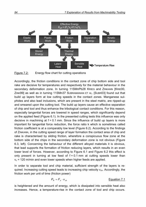
84 7 Explanation of Results from Machinability Testing
Effective Energy Eeff = (Fc*vc+Ff*vf)*tc
Separation Energy
Plastic Work
Friction Work
Kinetic Energy
Elastic Work
Stored Energy
Thermal Energy
Latent Heat
Sensible Heat Temperature Rise
Effective Energy Eeff = (Fc*vc+Ff*vf)*tc
Separation Energy
Plastic Work
Friction Work
Kinetic Energy
Elastic Work
Stored Energy
Thermal Energy
Latent Heat
Sensible Heat
Effective Energy Eeff = (Fc*vc+Ff*vf)*tc
Separation Energy
Plastic Work
Friction Work
Kinetic Energy
Elastic Work
Stored Energy
Thermal Energy
Latent Heat
Sensible Heat Temperature RiseTemperature Rise
Figure 7.2: Energy flow chart for cutting operations
Accordingly, the friction conditions in the contact zone of chip bottom side and tool rake are decisive for temperatures and respectively for the material behaviour in the secondary deformation zone. In turning 11SMnPb28 KRIEG and ZINKANN [KRIE00,ZINK99] as well as in turning 11SMn37 SUBRAMANIAN ET AL. [SUBR03] found out that build up layers form at low cutting speeds in the contact zones. Manganese sul-phides and also lead inclusions, which are present in the steel matrix, are ripped-up and smeared upon the cutting tool. The build up layers cause an effective separation of chip and tool and thus enhance the tribological contact conditions. For this reason, especially tangential forces are lowered in speed ranges, which significantly depend on the applied feed (Figure 6.1). In the presented cutting tests this influence was only decisive in machining at f = 0.1 mm. Since the influence of build up layers is more important for tangential force reduction, the force ratio k which is sometimes called friction coefficient is at a comparably low level (Figure 6.2). According to the findings of ZINKANN, in the cutting speed range of layer formation the contact area of chip and rake is characterised by sliding friction, wherefore a conspicuous flow zone at the bottom side of the chips in the secondary deformation zone is not obvious (Figure 6.3, left). Concerning the behaviour of the different alloyed materials it is obvious, that lead supports the formation of friction reducing layers, which results in an even lower level of forces. However, according to Figure 6.1 and Figure 6.2 this effect is only present in turning at low feed of f = 0.1 mm at cutting speeds lower than vc = 120 m/min and even lower speeds when higher feeds are applied.
In order to separate tool and chip material, sufficient strength of the layers is re-quired. Increasing cutting speed leads to increasing chip velocity vch. Accordingly, the friction work per unit of time (friction power)
chtR vFP Equation 7.1
is heightened and the amount of energy, which is dissipated into sensible heat also increases. Hence, a temperature-rise in the contact zone of tool and chip occurs.

7 Explanation of Results from Machinability Testing 85
Consequence of which is a reduction of build up layer strength and an impairment of the effectiveness with respect to tribological improvement of the contact conditions [KLOC97, KLOC98, KRIE00, ZINK99]. Further, the transportation of layers out off the contact zone by the chip is promoted when the chip velocity increases. This is also valid for lead inclusions, which are liquefied and contribute to friction reduction at low cutting speeds. At higher speeds lead is pushed out of the contact zone and cannot stick to the chip bottom side (Figure 5.6). Nevertheless, still MnS layers may be found on cutting tools, particularly when the cutting process is not stopped immedi-ately (quick stop) but under continuously decreasing mechanical and thermal load. These layers should not be regarded as effective layers, as they are not able to separate the surfaces of chip and tool [ZINK99]. Nevertheless, according to JIANG ET
AL. [JIAN96] and QI [QI00], the layers contribute to reduction of diffusive wear. Thereby, the geometry of the cutting tool seems to make a strong influence on the formation of build up layers. Compared to cutting with inserts of the specification SPUN with the CNMG type inserts much more MnS residues can be detected.
SPUN > CNMG
hch, SPUN < hch, CNMG
vch, SPUN > vch, CNMG
CNMG
hch, CNMGvch, CNMG
SPUN
vch, SPUN hch, SPUN
.
chch
cch
chc
chchch
ch
c
chchchchcc
chchchcc
c
hbhbvv
withhbhb
vv
vhbvhbvAvAconstvAm
MnS-layer MnS-
layer
1,1,
2,2,
2,
1, chch
chch
ch
ch
hbhb
vv
VC VC
SPUN > CNMG
hch, SPUN < hch, CNMG
vch, SPUN > vch, CNMG
CNMG
hch, CNMGvch, CNMG
SPUN
vch, SPUN hch, SPUN
.
chch
cch
chc
chchch
ch
c
chchchchcc
chchchcc
c
hbhbvv
withhbhb
vv
vhbvhbvAvAconstvAm
MnS-layer MnS-
layer
1,1,
2,2,
2,
1, chch
chch
ch
ch
hbhb
vv
VC VC
Figure 7.3: Chip flow as a result of different rake angles
The reason can be found in the tool geometry since SPUN inserts are characterised by a plane rake face showing a positive rake angle of = 6° and in contrast, the ap-plied CNMG inserts are characterised by a negative rake angle of = -1°. According to Figure 7.3 the rake angle makes a strong impact on the chip flow direction. In the left part of the figure an obtuse angle (> 90°) is reached between the cutting velocity vc and the chip velocity vch. Splitting the cutting speed vector up into a component

86 7 Explanation of Results from Machinability Testing
orthogonal to the rake and parallel to it, it is obvious, that latter contributes to chip flow. In contrast, in the right sketch an acute angle of vc and vch (< 90°) is visible. The consequence is a small component of the cutting velocity in the opposite direction of chip flow. Thus, in cutting with positive rake angles MnS layers are likely carried away by the chip and pressed out of the contact zone, whereas the increased resistance in chip flow direction (negative rake angles) supports the layers to adhere to the rake of the CNMG inserts. In addition, Figure 7.3 shows the continuity equation for the cut-ting process. It is obvious that the chip velocity mainly depends on chip thickness hch
and chip width bch when two processes with the same cutting parameters are com-pared. Due to stronger chip compression and therefore larger chip thickness and width in cutting with negative rake angle, the chip velocity decreases,. This is benefi-cial for the formation of effective layers.
As a result of cutting speed increase and changed contact conditions, work piece material more likely adheres to the cutting tool and the cutting process is character-ised by build up edge formation (Figure 5.12, Figure 5.17, Figure 6.19). Work piece material is strongly compressed by normal stresses in the primary deformation zone and adheres to the cutting tool. The build up edge forms by single work hardened material layers and takes on the function of the cutting edge [BERS71].
Chip
Tool
Workpiece
vc
Chip formationwithout BUE
Chip formationwith BUE
Chip formation withBUE “overhang“
Chip
Tool
Workpiece
vc
Chip formationwithout BUE
Chip formationwith BUE
Chip formation withBUE “overhang“
Figure 7.4: Build up edge formation (schematically)
As shown in Figure 7.4, a build up edge is not as sharp as the cutting tool. At some distance to the tool tip the rake angle is increased but in the area of the tool tip a sizeable radius is built. As a result of this modification of cutting conditions, the tan-gential as well as the normal forces rise. Considering the values for the force in-crease in machining 11SMnPb30 (Table 5.4) it can be seen that feed and thrust force show a stronger rise. This is due to the fact, that parts of the chip material stick to the cutting edge and build up edge respectively and thus material is torn out off the bot-tom side of the chip. This procedure can be revealed by means of the SEM images of irregular chip bottom sides in Figure 5.6 and Figure 7.5.
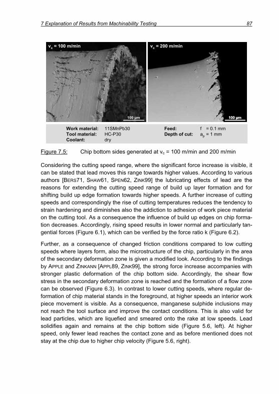
7 Explanation of Results from Machinability Testing 87
Work material: 11SMnPb30 Feed: f = 0.1 mmTool material: HC-P30 Depth of cut: ap = 1 mmCoolant: dry
vc = 100 m/min vc = 200 m/min
100 μm 100 μm
Work material: 11SMnPb30 Feed: f = 0.1 mmTool material: HC-P30 Depth of cut: ap = 1 mmCoolant: dry
vc = 100 m/min vc = 200 m/min
100 μm 100 μm100 μm
Figure 7.5: Chip bottom sides generated at vc = 100 m/min and 200 m/min
Considering the cutting speed range, where the significant force increase is visible, it can be stated that lead moves this range towards higher values. According to various authors [BERS71, SHAW61, SPEN62, ZINK99] the lubricating effects of lead are the reasons for extending the cutting speed range of build up layer formation and for shifting build up edge formation towards higher speeds. A further increase of cutting speeds and correspondingly the rise of cutting temperatures reduces the tendency to strain hardening and diminishes also the addiction to adhesion of work piece material on the cutting tool. As a consequence the influence of build up edges on chip forma-tion decreases. Accordingly, rising speed results in lower normal and particularly tan-gential forces (Figure 6.1), which can be verified by the force ratio k (Figure 6.2).
Further, as a consequence of changed friction conditions compared to low cutting speeds where layers form, also the microstructure of the chip, particularly in the area of the secondary deformation zone is given a modified look. According to the findings by APPLE and ZINKANN [APPL89, ZINK99], the strong force increase accompanies with stronger plastic deformation of the chip bottom side. Accordingly, the shear flow stress in the secondary deformation zone is reached and the formation of a flow zone can be observed (Figure 6.3). In contrast to lower cutting speeds, where regular de-formation of chip material stands in the foreground, at higher speeds an interior work piece movement is visible. As a consequence, manganese sulphide inclusions may not reach the tool surface and improve the contact conditions. This is also valid for lead particles, which are liquefied and smeared onto the rake at low speeds. Lead solidifies again and remains at the chip bottom side (Figure 5.6, left). At higher speed, only fewer lead reaches the contact zone and as before mentioned does not stay at the chip due to higher chip velocity (Figure 5.6, right).

88 7 Explanation of Results from Machinability Testing
In the secondary deformation zone, the effects of cutting speed enlargement are not only limited to process forces or chip formation. It also makes a significant influence on tool wear of the cemented carbide tool.
According to the continuum equation
const.vAm c Equation 7.2
the chip velocity vch can be calculated with
chch
cch hb
hbvv Equation 7.3
If chip thickness hch does not rise as a result of cutting speed enlargement, the chip velocity rises by about factor 2. Consequently, the friction power PR
chtR vFP Equation 7.4
also increases because the drop of tangential Force F t is not as strong as the rise of chip velocity (Figure 6.1). For instance between vc = 100 and 200 m/min the reduc-tion of F t is only 5 %. Assuming that the friction power is completely converted into heat and that convection by surrounding air can be neglected, friction power has to be equal to the heat fluxes into chip (dQch/dt) and tool (dQto/dt):
tochR QQP Equation 7.5
For the determination of heat flow into tool and chip as a result of friction on the rake the Fourier equation can be considered [BEIT90, ZIEB95]:
dxdAQ Equation 7.6
For similar areas A and temperature degrees d /dx, the ratio of heat flow into chip dQch/dt and tool dQto/dt is equal to the ratio of the respective heat conductivities:
to
ch
to
ch
Q
Q Equation 7.7
A more comprehensive appraisal for the ratio of heat flow into chip and tool can be given when density and specific heat coefficient cp are taken into account. There-fore, the heat permeation coefficient b is introduced [DETE99, KAMM92]
pcb Equation 7.8
and the ratio of heat flux into chip and tool is specified [KRIE00]

7 Explanation of Results from Machinability Testing 89
to,ptoto
ch,pchch
to
ch
to
ch
cc
bb
Q
Q Equation 7.9
Using equations 7.5 and 7.9, heat flux into the tool can be calculated:
to,ptoto
ch,pchch
cht
to
ch
Rto
cc
1
vF
bb1
PQ Equation 7.10
Thus, the strong increase of chip velocity implies intensified heat flow into tool and chip. Consequence of which is a rise in temperature shown in chapter 6.3. As a result the strength of the cemented carbide substrate material is lowered and abrasion by the bottom of the chips at the rake more likely occurs. Further, due to elevated tem-peratures iron is able to diffuse from the chip over the rake into the binding phase of the tool and cobalt from the tool into the chip material. As a result, tungsten carbide dissolves for the benefit of complex carbides like Fe3W3C, (FeW)6 and (FeW)23C6
[KOEN02]. The dissolution of tungsten carbide, which is responsible for hardness and wear resistance, causes weakening of the tool material and reduces the resistance of the substrate to abrasion. Consequently, distinctive crater wear on the rake becomes obvious (Figure 5.19, left and Figure 6.18, right).
In terms of the tertiary deformation zone, mainly the generation of work piece sur-faces and tool wear at the flank are in the focus. As mentioned before, the generation of build up edges has an important impact on chip formation and correspondingly on the topography of work piece surface. Build up edges enlarge the dimensions of the cutting tool as a kind of overhang [HOVI73], which results in deeper penetration of the work piece compared to a tool without build up edge (Figure 7.4). According to the SEM images in Figure 5.10 and Figure 6.8, the build up edge ploughs through the work piece material and causes plastic flow under the pressure of the cutting edge [ALBR60]. The ploughing process is supported by a low uncut chip thickness in the area of the nose radius, thus in the zone where the surface is generated. Finally, the build up edge decreases when parts of it migrate periodically over rake and particu-larly flank. Thereby, the build up edge constituting material is squeezed under high pressure by the tool flank onto the machined surface. As a consequence, the typical scaly surface topography characterised by single roughness peaks is generated, whereas the smeared material itself looks quite smooth with some marks mapped by the roughness of the cutting tool. Respectively, the scaly topography affects signifi-cantly the roughness values Ra and Rz (Figure 6.7). Increased cutting speed results in more regular surfaces (Figure 6.7, Figure 6.8, left). The reason can be found in the enlarged cutting temperatures which lead to a rise of ductility of the work piece mate-rial and diminish the tendency to adhesion, strain hardening and pressure welding, thus build up edge formation. SEM photographs of chip bottom sides and chip roots shown in chapters 5 and 6 confirm this conclusion.

90 7 Explanation of Results from Machinability Testing
Tool wear shapes and wear causes in machining the different alloyed free cutting steels also strongly depend on the applied cutting speed. At low speed of vc = 100 m/min strong notch wear, depicted in Figure 5.16 and Figure 6.17, deter-mines tool life. The manifold reasons for this wear pattern can be found in the ap-pearance of machined work piece surface in combination with the kinematical contact conditions. In the area of nose radius and minor cutting edge, the tool comes in con-tact with material, where a chip was separated in the preceding revolution. This af-fects tool wear in the following two ways. The material was already subject to plastic deformation and therefore to work hardening, which can be demonstrated by defor-mation zones in the work piece rim zones using light microscopy. In addition, those parts of the work piece surface which come in contact with nose radius and minor cutting edge are indicated by weld on build up edges of the previous revolution. Thus, the abrasive effect of the before machined work piece surface is extremely high. In order to strengthen these arguments, Figure 7.6 shows exemplary a light microscopic view of an etched longitudinal section of a work piece machined under the regarded cutting conditions.
Work material: 11SMn30+Sn
Cutting tool: SPUN120304
Tool material: HW-P10
Cutting speed: vc = 100 m/min
Feed: f = 0.2 mm
Depth of cut: ap = 1 mm
Coolant: dry
20 μm
Welded build up edge material
Roughnesspeak
Plasticallydeformed rim
zoneWork material: 11SMn30+Sn
Cutting tool: SPUN120304
Tool material: HW-P10
Cutting speed: vc = 100 m/min
Feed: f = 0.2 mm
Depth of cut: ap = 1 mm
Coolant: dry
20 μm
Work material: 11SMn30+Sn
Cutting tool: SPUN120304
Tool material: HW-P10
Cutting speed: vc = 100 m/min
Feed: f = 0.2 mm
Depth of cut: ap = 1 mm
Coolant: dry
20 μm20 μm
Welded build up edge material
Roughnesspeak
Plasticallydeformed rim
zone
Figure 7.6: Light microscopic view of a work piece rim zone
The before mentioned abrasive wear attack by the work piece surface is supported by the thermal boundary conditions in the contemplated area of the tool. The different conditions in the contact zone and beside it result in a complex stress distribution. During cutting the cemented carbide material tends to expand in those areas where high temperatures occur. This procedure results in compressive stresses since the cold material outside the contact zone does not expand. Once the cutting process ends and the temperature falls, the material contracts again leading to tensile stresses, which are extremely undesirable for cemented carbide tools [KOEN02,TOEN95]. This incident is mainly critical in interrupted cutting although it also has to be considered when the cutting time per cutting path is short due to high spindle speeds and short work piece lengths. In the current case, the time for one cut was only between 2.5 and 6.5 s, which means numerous cycles of heating up and cooling down until the end of the test was reached. Further, this area of the tool surface
7 Explanation of Results from Machinability Testing 91
comes in contact with the ambient air which results in a tribo oxidation wear as com-plex W-Co-Fe-oxides may be formed. These oxides cannot resist the abrasive attack of the work piece. Breakouts, especially at the minor cutting edge can be the conse-quence [CHAN94, GERS97, KOEN75].
As noted in chapters 0 and 6.3 the wear form changes with increasing cutting speed. Not any longer, wear at the minor but at the major flank of the tool terminates tool life which is the result of altering wear causes. The temperature rise of about 200 °C be-tween vc = 100 m/min and 200 m/min (chapter 6.3) is sufficient to cause a drop in hardness of the tool material by around 15 – 20 % [GEY05, KOEN02, TÖNS95]. Con-sequence of this loss in wear resistance is increased attack due to friction and abra-sion of hard work piece particles. Those steels, which cause most tool wear, showed biggest amounts of carbide particles sticking to the chip root. Thus, the abrasive ef-fect of the work piece material is supported by carbide particles, which break loose and squeeze through flank and machined work piece surface. Overall, for all materi-als the increased wear attack results in a tremendous decrease of tool life time.
7.2 Influence of Feed
The physical effects in machining low carbon free cutting steels were shown by means of the primary, secondary and tertiary deformation zone. Thereby, the strong influence of cutting speed was explained. In addition, also the adapted feed makes an important impact on the procedures during cutting. As shown in chapter 5.2 the cutting edge radius of the uncoated inserts amounted to rn = 24 μm. Respectively, the influence of cutting edge micro geometry on chip formation at low feed (f = 0.1 mm) is high, whereas it decreases when the feed is heightened. This is re-flected in the force ratio k shown in Figure 6.2. When low feed (f = 0.1 mm) is applied the ratio of tangential and normal force exceeds values of k = 0.7, whereas in ma-chining at medium feed (f = 0.2 mm) maximum force ratios lie between 0.6 and 0.7 and even lower than 0.6 when high feed (f = 0.4 mm) is used. Overall, the force level is higher for large feeds as the chip cross section increases. Accordingly, per time unit more energy is converted into heat because all force components rise due to increasing feed. Consequence of enlarged mechanical and thermal load is the movement of the cutting speed range where build up layers and build up edges occur towards lower cutting speeds (Table 5.4, Figure 6.1). This procedure is important for specific cutting forces kc1.1 and the (1-mc) values depicted in Figure 6.6. As men-tioned before at low uncut chip thickness and low speed (vc = 100 m/min) build up layers lead to low cutting forces. Increasing the uncut chip thickness the cutting forces increase due to higher chip cross sections and further due to the disappear-ance of effective layers. Consequently, the rise of the cutting force F’c as a function of uncut chip thickness (1-mc) is very high. In contrast, at higher speed (vc = 200 m/min) effective layer formation does not occur although low feed is applied and therefore the cutting force is mainly a function of uncut chip thickness, which results in lower

92 7 Explanation of Results from Machinability Testing
kc1.1 and (1-mc) values compared to vc = 100 m/min. Further, the feed is of particular significance for the effectiveness of cutting speed enlargement as especially at high feed thermal weakening effects in the primary deformation zone are beneficial for the process force level (Figure 5.3, Figure 6.1). Correspondingly, the values of kc1.1 lie on a lower level for high than for low cutting speed.
The enlargement of feed and thus the rise of chip thickness furthermore results in desirable chip forms. As shown in chapters 5.3.4 and 6.2.5 chip fracture is supported since strain in the rim one of the chip at the bottom side is heightened as a result of curling. For the sake of completeness, the impairing effect of feed on surface rough-ness has to be considered (Figure 6.7, Figure 6.8 and equations 5.6 and 5.7). Rising feed increases the height of surface profile peaks as a result of increased distance of feed marks, which arise from the kinematical contact conditions in cutting.
7.3 Influence of Tool Coating
In the screening and tool life tests presented in chapters 5 and 6 not only uncoated but also coated tools were used, which led to important changes. For the interpreta-tion of the results, first of all the micro geometry of the cutting edge has to be consid-ered. The cutting edge radius amounted to rn = 50 μm, which is twice as much in comparison to the uncoated inserts. It is well-known that the cutting edge roundness significantly affects the process forces as the proportion of plastic deformation rises [NAKA68, THIE99]. In the area where the flank passes into the rake over the cutting edge radius, a kind of negative rake angle emerges even though the share on the whole contact area is very small. KOENIG and KLOCKE [KOEN02] state, that the cutting force rises with every degree reduction of rake angle by about 1.5 %, which mainly explains the increased level of normal forces (Figure 6.4) compared to machining with uncoated inserts. The dependency of feed and thrust force is even stronger as these components rise by about 4 and 5 % respectively when the rake angle is low-ered by one degree, which results in a stronger increase of tangential force com-pared to normal force. This fact is reflected by the force ratio k (Figure 6.5) which consequently shows larger values when coated inserts are applied. In this context, it is self-evident that the force ratio should not be equated with the friction coefficient, since the TiN top layer of the coating contributes rather to friction coefficient reduc-tion [TOEN95] than to friction increase. Nevertheless, the friction power needs not to be lower in cutting with coated tools, because the chip velocity is higher than for un-coated tools. Figure 5.7 shows that chip thickness is larger for HW-P10 tools com-pared to HC-P30, which implies according to equation 7.3 a rise in chip velocity.
In machining with coated inserts, the chip material is only in contact with the coating, which causes a disturbance of heat flow into the tool. Respectively, coated carbide tools show lower heat permeation coefficients than uncoated inserts, which is charac-teristically for a slow down of heat removal from the contact zone and for a rise of heat flow into the chip. Accordingly, the temperature in the contact zone rises on

7 Explanation of Results from Machinability Testing 93
condition that the overall generated heat is similar for uncoated and coated tools [DETE99, DROE87, KAMM92, KRIE00]. In addition, KRIEG [KRIE00] emphasizes for cut-ting quench and tempering steel, that the portion of heat flow into tool and chip re-spectively is linked to the wear resistance of the cutting tool. The sliding chip causes abrasion of the uncoated carbide substrate on the rake and smoothes the tool sur-face. As a result, the effective contact zone of chip and tool grows and heat transfer towards the tool rises. In contrast, the high wear resistance of a coating delays the wear process. Consequently, the tangency of tool and chip is characterised by a higher amount of micro contacts instead of plane contacts in the case of uncoated tools. The heat transfer towards the coated tool is impaired and as a consequence the chip temperature rises. GRZESIK ET AL. [GRZE04] confirm these findings and show a rise of cutting temperature in machining with Ti(C,N)/Al2O3/TiN coated inserts com-pared to uncoated tools.
A connection between the transition speeds for build-up layer and build up edge for-mation respectively and the enlarged mechanical and thermal loads at elevated feeds has already been established. As shown before, in cutting with coated inserts the chip velocities are larger and the mechanical loads as well as the cutting tem-peratures higher compared to turning with uncoated tools. The mechanical loads strongly depend on the cutting edge radius, whereas the cutting temperature is sig-nificantly influenced by the coating (Figure 7.7). As a result, the state that build up layers on the cutting tools no longer appear is reached at lower cutting speeds. Fur-thermore, the cutting speed range where build up edges occur is also moved towards lower values. Hence, the run of the force curves is similar for uncoated and coated tools, but temperature driven changes in the machining process occur at lower speeds.
F P
Qto Qch
rn
Qch
Qto
uncoated, round
Qto
coated, round
tool
workpiece
vc
h
Qch
Qto
uncoated, sharp
F , P, Qto, Qch , F P
Qto Qch
•
• •
•
•
•••
••
Qch•
•F P
Qto Qch
rn
Qch
QtoQto
uncoated, round
Qto
coated, round
tool
workpiece
vc
h
Qch
Qto
uncoated, sharp
F , P, Qto, Qch , F P
Qto Qch
•
• •
•
•
•••
••
Qch•
•
Figure 7.7: Influence of cutting edge radius and coating in turning

94 7 Explanation of Results from Machinability Testing
However, not only the cutting temperatures are decisive for build up edge formation but also the conditions in the contact zones of tool and work material. Less work piece material adheres to the cutting tool since the cobalt rich cemented carbide is not in direct contact with the steel material but the coating, which shows stronger in-activity towards chemical reactions [ALTE58]. Build up edge formation can be signifi-cantly reduced. The material is cut at the tool tip and the chip slides on the tool rake rather than material adheres to the tip and welds with work piece and tool. Further, the increase of temperature at the minor cutting edge due to low heat permeation coefficient of the coating encourages flow chip formation at low speeds. Accordingly, the surface topography becomes conspicuously more regular (Figure 6.8 and Figure 6.9) when uncoated tools are substituted by coated ones. Comparing the roughness values Ra and RZ given in Figure 6.7 it is obvious that the beneficial effects of lead become less important since the coating already improves the conditions in the con-tact zone.
As shown in chapter 6.2.5 the application of coated inserts deteriorates chip break-age. The basic cause has to be seen in heightened formability of chip material as a result of high cutting temperatures and in the large cutting edge radius of the inserts. Accordingly, at f = 0.1 mm and vc > 120 m/min formation of tangled chips had to be observed.
The application of the multi layer coated insert results expectedly in both less crater and flank wear. The high temperature stable coating seals the substrate surface and prevents direct contact between cemented carbide and work piece material. Particu-larly, the Al2O3 coating shows excellent resistance against abrasive and diffusive wear combined with an entire insensitivity against oxidative wear attack [SCHE88].Consequently, diffusion processes between chip and tool material can be sup-pressed. Further, on the rake MnS layers could be detected (Figure 6.24). Although these layers are not believed to contribute to a reduction of friction due to low strength at high cutting temperatures, they are nevertheless able to reduce diffusive wear attack on the tool.
Flank wear is reduced as the coating shows a significantly higher level of hardness and thermal strength compared to cemented carbide (Figure 6.30). Often the tools show a wavy structure of the flank, which is caused by score marks running perpen-dicular to the major cutting edge. These marks originate in hard particles of substrate material or coating which break loose at the major cutting edge and afterwards mi-grate along the flank. This happens under very high pressure as the particles are squeezed between flank and the newly generated surface of the work piece. In so doing more hard particles broke loose and accelerated wear development. Admit-tedly, in machining 11SMn30+Sn further adhesion arises as problem. When work piece material sticks to the coating, parts of the coating are torn away. Afterwards, the uncoated cemented carbide substrate material cannot stand the high tool loads (Figure 6.24).
7 Explanation of Results from Machinability Testing 95
7.4 Influence of Cutting Fluid Application
The application of cutting fluid has an important impact on the machining perform-ance of low carbon free cutting steels. In chapters 0 and 6.3 it is focussed on the in-fluence of emulsion on tool wear, whereby inevitably the consequences of cutting fluid supply on process forces and surface generation also come to the fore.
The strong cooling effect of emulsion as a result of high water content improves heat removal in the cutting process. Nevertheless, this does not necessarily mean that that the temperatures in the contact zone of tool and work piece are lowered, be-cause the cutting fluid is mostly not able to reach the contact zone. Considering a constant load distribution over the contact zone, the cutting pressure pc can be ap-proximately calculated by the minimum normal force F n = 320 N and the contact zone of chip and tool A = 2.28 mm2):
bar14mm
N140A
Fp 2
nc Equation 7.11
Furthermore, especially at high cutting speeds the chip velocity impedes the cutting fluid from intruding into the contact zone since cutting fluid stream and chip show op-posite moving senses. As a consequence, temperatures of work piece and tool mate-rial can be lowered, but heat removal and lubrication in the contact zone seem im-probable due to high pressure and high velocity of the chip.
At low cutting speed of vc = 100 m/min flank wear at the minor cutting edge deter-mines tool life time in dry as well as wet cutting. The increase of wear attack and cor-respondingly decrease of tool life time by 50 – 60 % has to be linked to the cooling effect of emulsion in the area of the tertiary deformation zone. As before mentioned, in the area of nose radius and minor cutting edge the tool comes in contact with a surface, which was subject to plastic deformation and build up edge formation in the previous rotation.
Considering Figure 5.21 for 11SMnPb30 and Figure 7.8 representatively for non leaded steels it is obvious that in dry cutting the surface of the work piece is charac-terised by high peaks due to the kinematical contact conditions of tool and work piece. The tool passes the work piece while it deforms the material elastically in the area of the edge radius and minor cutting edge, where the uncut chip thickness is very low. Material is pushed towards the work piece and it springs back after the tool passed the described location. Certainly, this procedure happens very quickly as the tool moves forward with 1.67 m/s. The reduction in work piece temperature as a re-sult of cutting fluid application abates the elastic behaviour of the work piece material. This can be derived from the Young’s modulus, which declines with increasing tem-peratures, thus in the case of dry machining [HOPP04].
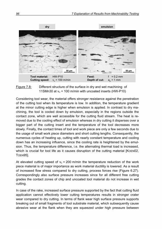
96 7 Explanation of Results from Machinability Testing
Tool material: HW-P10 Feed: f = 0.2 mmCutting speed: vc = 100 m/min Depth of cut: ap = 1 mm
emulsiondry
Tool material: HW-P10 Feed: f = 0.2 mmCutting speed: vc = 100 m/min Depth of cut: ap = 1 mm
emulsiondry
50 μm50 μm
Figure 7.8: Different structure of the surface in dry and wet machining of 11SMn30 at vc = 100 m/min with uncoated inserts (HW-P10)
Considering tool wear, the material offers stronger resistance against the penetration of the cutting tool when its temperature is low. In addition, the temperature gradient at the minor cutting edge is higher when emulsion is applied. In contrast to dry ma-chining, the tool is cooled down by emulsion, especially in the regions outside the contact zone, which are well accessible for the cutting fluid stream. The heat is re-moved due to the cooling effect of emulsion whereas in dry cutting it disperses over a bigger part of the cutting insert and the temperature of the tool decreases more slowly. Finally, the contact times of tool and work piece are only a few seconds due to the usage of small work piece diameters and short cutting lengths. Consequently, the numerous cycles of heating up, cutting with nearly constant temperature and cooling down has an increasing influence, since the cooling rate is heightened by the emul-sion. Thus, the temperature difference, i.e. the alternating thermal load is increased, which is crucial for tool life as it causes disruption of the cutting material [KOEN02,TOEN95].
At elevated cutting speed of vc = 200 m/min the temperature reduction of the work piece material is of major importance as work material ductility is lowered. As a result of increased flow stress compared to dry cutting, process forces rise (Figure 6.27). Correspondingly also surface pressure increases since for all different free cutting grades the contact zones of chip and uncoated tool material do not increase in wet cutting.
In case of the rake, increased surface pressure supported by the fact that cutting fluid application cannot effectively lower cutting temperatures results in stronger crater wear compared to dry cutting. In terms of flank wear high surface pressure supports breaking out of small fragments of tool substrate material, which subsequently cause abrasive wear at the flank when they are squeezed under high pressure between

7 Explanation of Results from Machinability Testing 97
work piece and tool. Further, flank wear is increased since work piece material in the tertiary deformation zone shows less elastic behaviour and therefore friction at the flank is considered to be higher. Although emulsion should contribute to friction re-duction, an increase at the flank seems reliable as the nozzle for cutting fluid supply was located on the top of the tool and therefore the cutting fluid stream approached the rake rather than the flank. Further in dry cutting it was shown that small build up edges deteriorated the cutting performance. Since the cutting speed range where build up edge formation occurs is shifted towards higher speeds as a result of cutting fluid application [PEKE74], it is probable that this effect also contributed to increased flank wear in wet cutting.
In conclusion, it can be summarised that in wet cutting with uncoated inserts tem-peratures in the contact zones cannot be effectively reduced, but mechanical and abrasive loads increase, which results in a loss of performance compared to dry cut-ting. Admittedly, in machining with coated inserts, the application of cutting fluid does not deteriorate the machining performance as the wear resistance of the tool is sig-nificantly improved by the hard and temperature resistant coating.

98 8 Fulfilment of the Requirements Regarding Machinability
8 Fulfilment of the Requirements Regarding Machinability
In the previous chapters a lot of machinability data for low carbon free cutting steels was described, which shows the capability of the different alloying elements to substi-tute for lead. Structuring into subchapters, the materials were compared regarding specific criterions for machinability. In order to merge the results of the cutting tests and to provide a tool for rating the different possibilities concerning machinability en-hancement, a benefit analysis is carried out. The benefit analysis is a planning tool for the systematic preparation of decisions [ZANG70]. Complex decisions are sup-ported by the correlation of different solution alternatives to a target system according to the preferences of the decision maker (Figure 8.1). The result is a ranking of the solution alternatives with respect to the fulfilment of the requirements given by the target system. The main advantages of this tool are the flexibility of the target system, which can be customised to particular demands, and the possibility of direct compari-son of different solutions [4MAN06, LUCZ99, ZANG70].
Material 1
Material 3Material 2
Material 4Material 5Material 6
Target 1
Target 4
Target 2
Target 3
Material 4
Material 1Material 6
Material 3Material 5Material 2
Utility analysis
Target 1
Target 3
Target 2
Target 4
Weighting
Target 3
Target 4
Target 1
Target 2
Material 1
Material 3Material 2
Material 4Material 5Material 6
Target 1
Target 4
Target 2
Target 3
Material 4
Material 1Material 6
Material 3Material 5Material 2
Utility analysis
Target 1
Target 3
Target 2
Target 4
Weighting
Target 3
Target 4
Target 1
Target 2
Figure 8.1: Schematic view of the benefit analysis and the weighting procedure [4MAN06]
8.1 Target System
The first step within the benefit analysis is the systematic establishment of the target system, which can be divided into two stages. Firstly, it is important to determine the targets and evaluation criteria respectively for decision making. Since the objective of the present case is the evaluation of machinability of different alloyed steels, this first stage has already been done prior to testing. Accordingly, the targets for the benefit analysis are equal to the machinability criteria listed in chapter 5.
Process forces
Surface quality
Chip form
Tool wear

8 Fulfilment of the Requirements Regarding Machinability 99
To complete the target system, in the second stage the single targets have to be weighted (Figure 8.1, right) symbolised by the weighting factor gi. Thereby, the as-sessment of the different criteria for machinability (i.e. targets) strongly depends on a subjective view and is driven by the particular machining task. For instance, in face milling processes chip form will be more or less irrelevant, whereas in gun drilling it will come to the fore. Another self-evident example is the importance of surface qual-ity in roughing or finishing operations. Nevertheless, a feasible rating (Table 8.1) can be given under the condition that all weighting factors must add up to
1g4
1i Equation 8.1
Target Symbol Rating Explanation
Process forces g1 0.1
Comparably low process forces for low carbon free cutting steels
Main importance when small or long cantilevering tools or instable fixtures and machine tools are used
Predictable
Surface quality g2 0.2
Depending on the requirements, surface quality can influence productivity
Predictable
Chip form g3 0.4
Chip breakage problems may lead to chip jamming resulting in tool breakage
Disturbance of automation Probably not predictable
Tool wear g4 0.3
Tool change is time- and cost-intensive Tool wear affects part quality Probably predictable
Table 8.1: Rating of different targets gi
8.2 Assessment of Performance
In this second step of the benefit analysis the different alloyed materials are as-sessed in respect of the target system and visualised by a degree of performance wij.Thereby, index i represents the evaluation criterion and index j the work piece mate-rial. The allocation of the performance degrees results from the machinability tests in chapter 6. As it was shown, that the results extensively depended on the applied cut-ting material, a separate examination has to be done for uncoated (HW) and coated (HC) tools respectively.

100 8 Fulfilment of the Requirements Regarding Machinability
Processforces
Surfacequality
Chip form
Tool wear
i = 1 i = 2 i = 3 i = 4
11SMn37 j = 1 w11, HW = 5 w11, HC = 5
w21, HW = 6 w21, HC = 8
w31, HW = 4 w31, HC = 3
w41, HW = 7w41, HC = 7
11SMn30+Sn j = 2 w12, HW = 4 w12, HC = 4
w22, HW = 4 w22, HC = 8
w32, HW = 2 w32, HC = 2
w42, HW = 5 w42, HC = 2
11SMn30+Sn+Cu j = 3 w13, HW = 4 w13, HC = 5
w23, HW = 3 w23, HC = 8
w33, HW = 4 w33, HC = 4
w43, HW = 5 w43, HC = 7
11SMnPb30 j = 4 w14, HW = 8 w14, HC = 8
w24, HW = 8 w24, HC = 8
w34, HW = 8 w34, HC = 8
w44, HW = 8w44, HC = 4
11SMn30 j = 5 w15, HW = 5 w15, HC = 6
w25, HW = 4 w25, HC = 9
w35, HW = 4 w35, HC = 5
w45, HW = 3 w45, HC = 7
11SMn30+Bi j = 6 w16, HW = 5 w16, HC = 5
w26, HW = 7 w26, HC = 9
w36, HW = 9 w36, HC = 6
w46, HW = 4 w46, HC = 9
Table 8.2: Degree for performance wij for the different materials (j) in respect of the evaluation criteria (i)
Table 8.2 displays the performance degrees of all materials for each evaluation crite-rion. As the objective of this work was to find possible alternatives to lead in machin-ing, the degrees of performance wi4 for the leaded steel were set to 8 (very good). Admittedly, one exception had to be made as the tool wear performance of leaded steel was comparably low in cutting with coated tools, particularly at higher cutting speeds. Since 11SMnPb30 is the basis for comparison of the different alloyed mate-rials, the performance degrees wi4 are indicated with bold letters. Out of the non-leaded steels the best performance in each category is also highlighted in bold letters for the application of uncoated (HW) and coated (HC) tools.
8.3 Evaluation of the Benefit
After assessing the performance of the different alloyed materials via the characteris-tic value wij, the degree of performance has to be correlated with the weighting factor gi, which was defined in the first step.
ijiij wgwg Equation 8.2
The following Table 8.3 shows the single utilities wgij for the special case that the tar-gets are weighted according to Table 8.1. However, using the before listed equations the utilities can also be calculated for modified weightings. Nevertheless, the per-formance of the different materials with respect to the single evaluation criteria is quite congruent and therefore a large deviation from the presented result is not ex-pected.
0 Unusable
1 Insufficient
2 Weak
3 Acceptable
4 Sufficient
5 Satisfying
6 Good butminor deficiency
7 Good
8 Very good
9 In excess of the goal
10 Optimum

8 Fulfilment of the Requirements Regarding Machinability 101
Processforces
Surfacequality
Chip form
Tool wear
i = 1 i = 2 i = 3 i = 4
11SMn37 j = 1 wg11, HW = 0.5 wg11, HC = 0.5
wg21, HW = 1.2 wg21, HC = 1.6
wg31, HW = 1.6 wg31, HC = 1.2
wg41, HW = 2.1 wg41, HC = 2.1
11SMn30+Sn j = 2 wg12, HW = 0.4 wg12, HC = 0.4
wg22, HW = 0.8 wg22, HC = 1.6
wg32, HW = 0.8 wg32, HC = 0.8
wg42, HW = 1.5 wg42, HC = 0.6
11SMn30+Sn+Cu j = 3 wg13, HW = 0.4 wg13, HC = 0.5
wg23, HW = 0.6 wg23, HC = 1.6
wg33, HW = 1.6 wg33, HC = 1.6
wg43, HW = 1.5 wg43, HC = 2.1
11SMnPb30 j = 4 wg14, HW = 0.8 wg14, HC = 0.8
wg24, HW = 1.6 wg24, HC = 1.6
wg34, HW = 3.2 wg34, HC = 3.2
wg44, HW = 2.4 wg44, HC = 1.2
11SMn30 j = 5 wg15, HW = 0.5 wg15, HC = 0.6
wg25, HW = 0.8 wg25, HC = 1.8
wg35, HW = 1.6 wg35, HC = 2.0
wg45, HW = 0.9 wg45, HC = 2.1
11SMn30+Bi j = 6 wg16, HW = 0.5 wg16, HC = 0.5
wg26, HW = 1.4 wg26, HC = 1.8
wg36, HW = 3.6 wg36, HC = 2.4
wg46, HW = 1.2 wg46, HC = 2.7
Table 8.3: Single utilities for the whole target system
The single utilities give information about the fulfilment of the requirements regarding each evaluation criterion. The higher the wgij value, the better is the performance of the material. Finally, using Table 8.3 the utilities for each material Gwgj can be calcu-lated as the sum of the single utilities wgij:
4
1
4
1ijiijj wgwgGwg Equation 8.3
Figure 8.2 illustrates the benefit values and the ranking of the materials. Obviously, in machining with uncoated carbide inserts, leaded steel 11SMnPb30 ranks first. Small process forces, good surface quality, desirable chip breakage and low tool wear can be given as reason. The Bi added material comes in second. Particularly, chip breakage has to be emphasised. The benefit 6.7 shows minor deficiencies, which mainly arise from process forces and tool wear behaviour. Next best material is the high sulphur variant 11SMn37. Here, specifically chip breaking problems impaired the benefit. Comparing both tin added steels, the high Cu variant was preferable in respect of chip breakage. 11SMn30 has deficiencies mainly regarding tool wear, whereas it performs better than 11SMn30+Sn in terms of chip forms, process forces and surface quality.
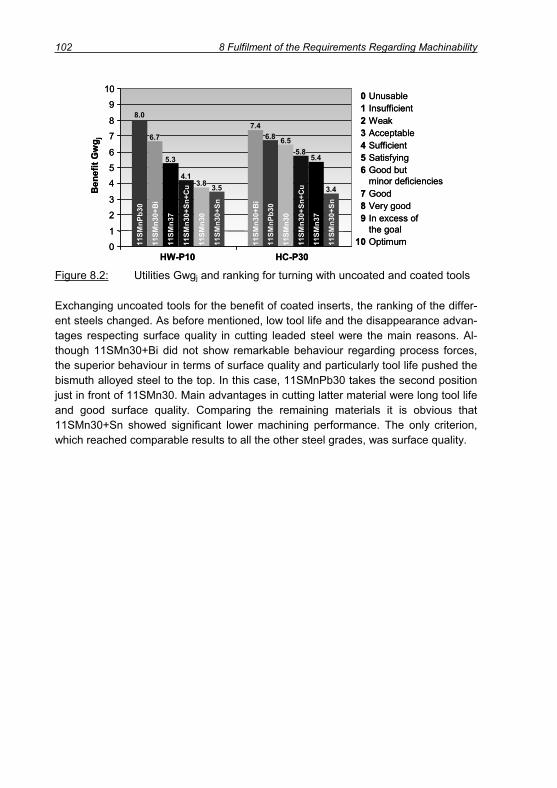
102 8 Fulfilment of the Requirements Regarding Machinability
0 Unusable1 Insufficient2 Weak3 Acceptable4 Sufficient5 Satisfying6 Good but
minor deficiencies7 Good8 Very good9 In excess of
the goal10 Optimum
Ben
efit
Gw
g j
HW-P10
8.0
6.7
5.3
3.8
6.8
5.8
3.5
0
1
2
3
45
6
78
9
10
7.4
HC-P30
5.4
3.4
4.1
6.511
SMn3
0+B
i
11SM
n30
11SM
n30+
Sn
11SM
nPb3
0
11SM
n30+
Sn+C
u
11SM
n37
11SM
n30+
Bi
11SM
n30+
Sn
11SM
nPb3
0
11SM
n30+
Sn+C
u
11SM
n30
11SM
n37
Figure 8.2: Utilities Gwgj and ranking for turning with uncoated and coated tools
Exchanging uncoated tools for the benefit of coated inserts, the ranking of the differ-ent steels changed. As before mentioned, low tool life and the disappearance advan-tages respecting surface quality in cutting leaded steel were the main reasons. Al-though 11SMn30+Bi did not show remarkable behaviour regarding process forces, the superior behaviour in terms of surface quality and particularly tool life pushed the bismuth alloyed steel to the top. In this case, 11SMnPb30 takes the second position just in front of 11SMn30. Main advantages in cutting latter material were long tool life and good surface quality. Comparing the remaining materials it is obvious that 11SMn30+Sn showed significant lower machining performance. The only criterion, which reached comparable results to all the other steel grades, was surface quality.
9 Transfer of Results 103
9 Transfer of Results
A detailed investigation of the machinability of different low carbon free cutting steels was given in chapter 6. Thereby the main aim was to see if steels alloyed with Sn, Bi, with increased S content or just the steel without any specific alloying element were capable of achieving the same cutting performance as leaded steel in a turning proc-ess. In order to verify whether the results obtained in machining free cutting steels of type 11SMn30 in turning are transferable, on the one hand further processes were investigated and on the other hand other steel types were investigated. Therefore, different alloyed steels of the C45 type and 16MnCr5 type came into operation.
9.1 Auto Lathe Test
Low carbon free cutting steels like the investigated 11SMn30 type are typically used on multi spindle turning centres and on auto lathes in order to allow for high produc-tivity and low cycle times. Since the main investigations focussed on external turning further machining tests should prove if the investigated materials were also usable for other processes. Therefore, a test component according to Figure 9.1 was ma-chined on a Traub lathe TNS42 with automatic bar feeder in the displayed sequence (numbers 1 – 5). The external turning process was conducted after grooving in order to increase the mechanical load on the insert due to tool entries and exits. Exclu-sively, coated cemented carbide tools were used in a dry cut and with emulsion as cutting fluid. In external turning only the cutting speed was varied, whereas in groov-ing and parting cutting speed and feed were changed to a degree that the material removal rate was kept constantly.
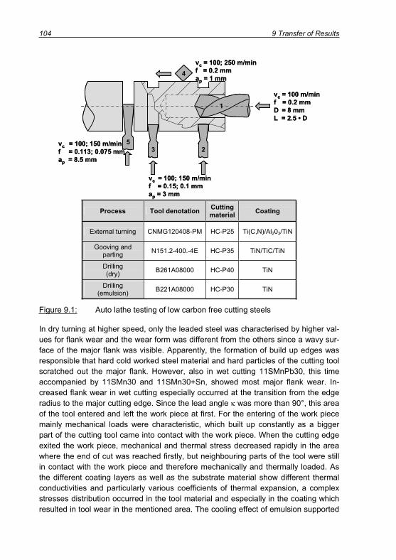
104 9 Transfer of Results
vc = 100 m/minf = 0.2 mmD = 8 mmL = 2.5 • D
vc = 100; 250 m/minf = 0.2 mmap = 1 mm
vc = 100; 150 m/minf = 0.15; 0.1 mmap = 3 mm
vc = 100; 150 m/minf = 0.113; 0.075 mmap = 8.5 mm
1
23
4
5
vc = 100 m/minf = 0.2 mmD = 8 mmL = 2.5 • D
vc = 100; 250 m/minf = 0.2 mmap = 1 mm
vc = 100; 150 m/minf = 0.15; 0.1 mmap = 3 mm
vc = 100; 150 m/minf = 0.113; 0.075 mmap = 8.5 mm
1
23
4
5
Process Tool denotation Cuttingmaterial Coating
External turning CNMG120408-PM HC-P25 Ti(C,N)/Al203/TiN
Gooving and parting N151.2-400.-4E HC-P35 TiN/TiC/TiN
Drilling(dry) B261A08000 HC-P40 TiN
Drilling(emulsion) B221A08000 HC-P30 TiN
Figure 9.1: Auto lathe testing of low carbon free cutting steels
In dry turning at higher speed, only the leaded steel was characterised by higher val-ues for flank wear and the wear form was different from the others since a wavy sur-face of the major flank was visible. Apparently, the formation of build up edges was responsible that hard cold worked steel material and hard particles of the cutting tool scratched out the major flank. However, also in wet cutting 11SMnPb30, this time accompanied by 11SMn30 and 11SMn30+Sn, showed most major flank wear. In-creased flank wear in wet cutting especially occurred at the transition from the edge radius to the major cutting edge. Since the lead angle was more than 90°, this area of the tool entered and left the work piece at first. For the entering of the work piece mainly mechanical loads were characteristic, which built up constantly as a bigger part of the cutting tool came into contact with the work piece. When the cutting edge exited the work piece, mechanical and thermal stress decreased rapidly in the area where the end of cut was reached firstly, but neighbouring parts of the tool were still in contact with the work piece and therefore mechanically and thermally loaded. As the different coating layers as well as the substrate material show different thermal conductivities and particularly various coefficients of thermal expansion, a complex stresses distribution occurred in the tool material and especially in the coating which resulted in tool wear in the mentioned area. The cooling effect of emulsion supported

9 Transfer of Results 105
the stress situation since those parts of the insert which were in direct contact with the emulsion stream were cooled down, whereas the tool areas which were still in contact with the tool were not efficiently chilled. Thus, the temperature gradient in machining under cutting fluid supply rose, consequent of which was diminished tool life. Summarising the wear measurements at high and low speed combined with dry and wet cutting respectively, most promising materials were 11SMn37, 11SMn30+Sn+Cu and particularly 11SMn30+Bi.
Concerning the productivity of the cutting process it can be concluded, that high cut-ting speeds are preferable since tool wear after the same amount of parts was equal in machining at low and high speed. Hence, the quantity is the same but the produc-tion time is significantly reduced in cutting at higher speeds. Admittedly, this was not valid for 11SMnPb30 and 11SMn30+Sn since these grades gave better performance at low speed. Further, the increased temperatures in dry cutting at high cutting speed supported the generation of the comparably best surface qualities with arithmetic mean values of Ra = 1.42 – 1.93 μm and peak to valley heights of Rz = 7.9 – 10.25 μm. Thereby, a significant advantage of one steel was not obvious, but 11SMnPb30 always counted among the best materials with regard to surface quality.
11SMnPb3011SMn30+Sn+Cu
Tool material: HC-P30 Feed: f = 0.1 mmCoating: TiN/TiC/TiN Depth of cut: ap = 3 mmCutting speed: vc = 150 m/min Coolant: dry
750 μm 750 μm
150 μm150 μm
Figure 9.2: Tool wear in dry grooving of different free cutting steels after 1000 machined grooves
In grooving different wear behaviour compared to external turning could be observed. Abrasive wear effects stepped back and adhesive wear came to the fore owing to lower cutting speeds and smaller chip cross sections. Work piece material stuck to

106 9 Transfer of Results
the cutting edge and welded together with the coating (Figure 9.2). This was caused by the special conditions during grooving. After entering the work piece and reaching a steady state, cutting speed and uncut chip thickness were constant. Approaching the end of the groove, the chip thickness and thus the cutting force decreased con-stantly to zero. The minimum uncut chip thickness was under-run. In this phase, the tool rubbed at the work piece surface, whereby work material adhered on the cutting tool. Once the tool started moving back out of the groove, three kinds of separation of tool and work piece were possible:
1. Separation between adhered material and tool. This was a desirable proce-dure as the bonding of tool coating and adhered material was not strong and therefore tool and coating were not affected.
2. Separation between coating and tool substrate. The result was delamination of coating since the bonding of steel and coating was stronger compared to the cohesion of coating and tool substrate.
3. Separation between adhered material and work piece. In this case, the adhe-sions stayed on the top of the tool, again characterised by strong cohesion. When the cutting edge became engaged with the work piece again, the adhe-sions were being sheared away eventually resulting in partial delamination of the tool coating.
Coating delamination could be observed for all combinations of work piece materials and cutting conditions. However, it was obvious that on the work material side alloy-ing with Pb (Figure 9.2) and on the process side the application of emulsion reduced material adhesion as the tribological contact conditions of work piece material and tool surface were supported. Admittedly, the supply of cutting fluid improved the per-formance only at the major cutting edge but it supported coating delamination at the minor cutting edge (Figure 9.3, left).
However, the inserts were used for 1000 grooves and only few abrasive wear of the coating was visible but the substrate material was not exposed over a big area yet. A reason can be found in the formation of build up layers from MnS, which protected rake as well as flank against abrasive wear attack. The right part of Figure 9.3 shows an SEM image of an insert used for grooving 11SMn37 at vc = 150 m/min and f = 0.1 mm in a dry cut. Layers consisting of manganese and sulphur could be found along the whole major cutting edge, whereby the size of the residues was mostly smaller than in the SEM photo.
The parting process was characterised by different conditions compared to grooving. Once the tool had entered the work piece it was a steady state process, where the feed was not slowed down at the end of the cut like in grooving. Since the cutting speed was hold constantly, the spindle accelerated rapidly with decreasing effective work piece diameter. Before the cutting tool reached the centre line of the work piece, the test component was torn off the work piece bar as a result of the increased

9 Transfer of Results 107
centrifugal force at rotational speeds of about 5,500 rpm. Hence, a tool exit charac-terised by decreasing uncut chip thickness and low cutting forces did not happen as the chip root was separated from the tool suddenly. Therefore, the parting tools did not show coating delamination due to adhesion like in grooving. Nevertheless, de-lamination of coating at the minor cutting edge and the prevention against abrasion by MnS-layers were similar to grooving.
Regarding the performance of the different alloyed steel grades it can be summa-rised, that the leaded steel showed superior behaviour in the cutting processes grooving and parting, which were characterised by low cutting speeds and low feeds due to its lubricating effect. Out of the non-leaded steels, the Bi-added variant seems to be the best alternative to 11SMnPb30.
Layer (MnS)Coating (TiN/TiC/TiN)
Adhered freecutting steel
vc = 150 m/minf = 0.1 mm
Dry
vc = 100 m/minf = 0.15 mm
Emulsion
Layer (MnS)
Adhered material(Mn, Fe, S)
Substrate(WC, (Ti, Ta, Nb)C, Co)
Coating (TiN/TiC/TiN)
400 μm400 μm
20 μm 100 μm
Layer (MnS)Coating (TiN/TiC/TiN)
Adhered freecutting steel
vc = 150 m/minf = 0.1 mm
Dry
vc = 100 m/minf = 0.15 mm
Emulsion
Layer (MnS)
Adhered material(Mn, Fe, S)
Substrate(WC, (Ti, Ta, Nb)C, Co)
Coating (TiN/TiC/TiN)
400 μm400 μm
20 μm 100 μm
Figure 9.3: Coating delamination at the minor cutting edge (left) and formation of build up layers from MnS (right) in machining 11SMn37
The drills were used for the production of 1,000 holes. Constant flank wear along the major cutting edge was not visible. Here, again the deposit of protecting layers could be detected. Nevertheless, detachment of coating in the form of big scratches was obvious at the minor flank towards the cutting edge corner. In this area the drill rubbed in the bore hole, which caused micro abrasion. Further, in wet cutting ad-hered material could be detected in those areas where the carbide substrate was

108 9 Transfer of Results
exposed. Since external cooling was applied, it can be concluded, that the cutting fluid was able to cool down work piece and tool, but not to penetrate into the contact area of work piece and tool and to lubricate the cutting zone. The extent of tool wear could be reduced when a change from wet to dry cutting was carried out. Probably, the heightened temperature in dry cutting and the especially for dry cutting designed coating were beneficial for the machining performance regarding the different work piece materials it can be stated that the best results were achieved for 11SMn37, most tool wear characterised the tool used for drilling 11SMn30. However 1,000 holes did not cause that much wear, that the end of tool life was already reached.
9.2 Machinability Enhancement of Carbon Steels (C45)
9.2.1 Screening Test
The resulting forces measured in screening five different carbon steels according to chapter 4.2 are illustrated in Figure 9.4. The uncoated carbide tools with the designa-tion SPUN120308 were similar to those used for screening the free cutting steels (see Table 5.3) but due to the higher depth of cut (ap = 2 mm), a larger nose radius of r = 0.8 mm was chosen.
The resulting force Fres in cutting at a feed of 0.1 mm varied mainly in a range of 550 – 700 N, but a clear dependency of the cutting forces on the cutting speed was not obvious at this feed. The biggest difference in forces for the various materials could be noticed at vc = 50 m/min. The leaded and Bi added steels seem to show benefits from low melting inclusions, which result in force reduction. In contrast, when applying a higher feed of f = 0.25 a cutting speed increase between 50 and 250 m/min influenced the cutting forces in a positive way. Thermal weakening and therefore reduction of flow stress led to reduced mechanical loads. Admittedly, ther-mal loads increased and therefore the forces rose again when higher speeds were applied as a result of tool wear. Since uncoated carbide tools were used, already af-ter a very short time, tool wear influenced the cutting force measurement. For this reason, at f = 0.4 mm only a small range of cutting speeds was applied, where the influence of thermal weakening on the process forces became visible.
Similar to the force measurements on the free cutting steels, mainly a positive impact of Pb additions could be detected. It can be concluded, that the lubricating effect of lead in the contact zone of tool and work piece and the effects in the primary shear zone were responsible for the force reduction. Further, especially at high feed, the alloy characterised by 0.045 % Bi performed very well.

9 Transfer of Results 109
250
400
550
700
850
1000
1250
1400
1550
1700
1850
2000
0 50 100 150 200 250 300 350 400Cutting speed vc / (m/min)
f = 0.1 mm
f = 0.4 mm
Res
ultin
gfo
rce
F res
/ N
850
1000
1150
1300
1450
1600
0 50 100 150 200 250 300 350 400Cutting speed vc / (m/min)
f = 0.25 mm
Res
ultin
gfo
rce
F res
/ NCutting tool: SPUN120308Tool material: HW-P10Depth of cut: ap = 2 mmCoolant: dryCutting length: lc = 50 mm
C45 C45+PbC45+Sn
C45+Ca
C45+Bi
Figure 9.4: Resulting forces in dry turning of carbon steels using uncoated ce-mented carbide tools (HW-P10)
In order to get an impression of the cutting temperatures and to see any effect of al-loying elements on the temperature, measurements using the two-colour pyrometer described in chapter 6.3 were conducted. The temperatures measured at the bottom side of the chip are illustrated in Figure 9.5. Applying a cutting speed of vc = 100 m/min the measured temperatures lay in a range 590 – 680°C. A positive effect of alloying with lead could be made out as the temperature in cutting C45+Pb (590°C) was obviously lower compared to the variants with Bi and Sn (640°C each) and with Ca (650°C). However, the strongest difference aroused in comparison with plain unalloyed C45 (680°C). Duplicating the cutting speed resulted in a temperature increase by around 20 %, which is comparable to the temperature rise in cutting the resulphurised low carbon steels. Thereby, the clear advantage of lead diminished as C45+Pb (700°C), C45+Bi (710°C) and C45+Ca (720°C) showed quite similar tem-peratures. Nevertheless, all mentioned materials caused lower cutting temperatures and thus lower thermal tool load compared to C45 and the Sn variant (780°C each).

110 9 Transfer of Results
0
100
200
300
400
500
600
700
900
Tem
pera
ture
/ °C
680
590640 650 640
780700
780720 710
C45
C45
+Pb
C45
+Sn
C45
+Ca
C45
+Biv c
= 10
0 m
/min
v c=
200
m/m
in
Work piece material
Cutting tool: SPUN120308
Tool material: HW-P10
Feed: f = 0.25 mm
Depth of cut: ap = 2 mm
Coolant: dry
800
0
100
200
300
400
500
600
700
900
Tem
pera
ture
/ °C
680
590640 650 640
780700
780720 710
C45
C45
+Pb
C45
+Sn
C45
+Ca
C45
+Biv c
= 10
0 m
/min
v c=
200
m/m
in
Work piece material
Cutting tool: SPUN120308
Tool material: HW-P10
Feed: f = 0.25 mm
Depth of cut: ap = 2 mm
Coolant: dry
800
Figure 9.5: Temperatures at the bottom side of the chips in turning C45 grades
In terms of chip breakage, the results from turning different alloyed carbon steels of the C45 type confirmed those results from machining the low carbon free cutting steels of 11SMn30 type as a significant benefit of lead and also bismuth could be detected. Mainly, long comma, spiral and tubular chips were produced at all combi-nations of feeds and speeds for these two steels. For all the other materials, the chip breakage depended significantly on the feed. Using plane inserts (SPUN120308) at a feed f = 0.1 mm only the formation of tangled chips was observed. Applying a clamped chip breaker, critical chip forms could only be avoided when machining the variant alloyed with Sn, whereas C45 and the Ca alloyed material still showed unde-sirable tangled chips. At elevated feed of f = 0.25 mm chip breaking problems still occurred for C45 and C45+Ca at cutting speeds vc = 200 – 300 m/min. Nevertheless, the use of a chip breaker led to short breaking chips for all the materials at each speed and a feed f = 0.25 mm. Increasing the feed to a value f = 0.4 mm, short breaking comma, spiral and corkscrew chips were produced for all materials in the whole range of cutting speeds due to increased stresses in the rim zone of the chips.
9.2.2 Tool Wear Test
A short term tool life test, where each steel was machined with uncoated inserts at constant depth of cut ap = 2 mm and constant feed f = 0.25 mm for a cutting time of tc = 8 minutes caused largest tool wear in dry turning of C45+Sn. At a cutting speed of vc = 300 m/min, the need for a tool coating became obvious as crater and notch wear at the major cutting edge were very distinctive as a result of increased cutting temperatures. This is unsurprising since the temperatures in the contact zone already amounted up to 780°C at vc = 200 m/min and it can be assumed that a further boost of cutting power due to rising speed resulted in a further increase of cutting tempera-tures. However, in the short term test the clearest result was the reduction of tool wear as a result of alloying with bismuth and calcium at higher speeds, whereby the calcium variant caused less crater wear compared to C45+Bi.

9 Transfer of Results 111
The enhanced performance of steel with calcium additions can be put down to the modification of inclusions and the formation of build up layers. Sharp-edged, very hard oxide inclusions, which usually cause unpleasant abrasive wear, were con-verted into globular, plastic and comparably low melting calcium aluminates. The sul-phides often jacket this kind of inclusions, but they also can stay as single MnS inclu-sions with a globular shape, which is encouraged by adding calcium similarly as lead does. As a consequence of inclusion modification, the abrasive wear in machining could be lowered. Admittedly, the highest potential regarding machinability enhance-ment of Ca treated steels has to be seen in the formation of build up layers consisting of manganese, sulphur, calcium and oxygen, which have a lubricating effect and therefore reduce adhesive and abrasive wear. Further, these layers act as diffusion barriers and contribute to temperature reduction in the contact zone. In machining the free cutting steel type 11SMn30 sulphide inclusions were also capable of reduc-ing friction, forces and tool wear at low cutting speeds. In contrast, when machining Ca added C45 steel the effective layer formation contributes to a decrease of tool wear even at high cutting speeds [APPL89, AREN04, BLETT90, CHIL90, GRAH94,HAMA96, JIAN94, KOEN65, KLOC96, KLOC97, KLOC98, NORD90, PADU91, PAJU91,PICK89, QI96, TOEN89, YAMA90].
The results from short term tool life testing were supplemented by long term tests with coated carbide tools similar to Figure 6.28. The results confirmed the benefit regarding tool wear reduction when adding Bi or Ca.
0
50
100
150
200
250
300
350
400
0 1000 2000 3000 4000 5000 6000 0 500 1000 1500 2000 2500 3000
Cutting length lc / m
Flan
k w
earV
BB
,C/ μ
m
Cutting length lc / m
Cutting time tc / min4 8 12 200 24 1.7 3.3 5 6.7 8.30 10
Cutting time tc / min
Tool material: HC-P25 Feed: f = 0.25 mmCoolant: dry Depth of cut: ap = 2 mm
vc = 250 m/min vc = 300 m/min
C45 C45+Pb
C45+SnC45+Ca
C45+Bi
16
Figure 9.6: Tool wear progression in machining different alloyed C45 steels
Adhesive wear in combination with abrasion and diffusion mechanisms resulted in wear on both rake and flank. When the coating was worn out or damaged and sub-sequently the cemented carbide substrate was uncovered, the wear resistance of the

112 9 Transfer of Results
cutting tool diminished. This resulted in a change from linear increase towards a pro-gressive evolution of flank wear. Figure 9.6 shows the development of flank wear for the different materials at cutting speeds 250 m/min and 300 m/min. At both speeds most tool wear could be observed in cutting non alloyed C45 steel. Longer tool life was dound for the leaded and the Sn added steel, where it should be emphasised, that the run of the tool wear curve for leaded and Sn added steel were very similar. Nevertheless, the best results were achievable for the grades alloyed with Bi or Ca.
C45+Pbtc = 16.6 min
C45+Catc = 18.6 min
Work material: C45+Ca, C45+Pb
Cutting tool: CNMG120408
Tool material: HC-P25
Cutting speed: vc = 250 m/min
Feed: f = 0.25 mm
Depth of cut: ap = 2 mm
Coolant: dry
TiN
Substrate(WC, (Ti, Ta, Nb)C, Co)
Al2O3
Ti(C,N)
500 μm500 μm
10 μm
C45+Pbtc = 16.6 min
C45+Catc = 18.6 min
Work material: C45+Ca, C45+Pb
Cutting tool: CNMG120408
Tool material: HC-P25
Cutting speed: vc = 250 m/min
Feed: f = 0.25 mm
Depth of cut: ap = 2 mm
Coolant: dry
TiN
Substrate(WC, (Ti, Ta, Nb)C, Co)
Al2O3
Ti(C,N)
500 μm500 μm
10 μm
Figure 9.7: Inserts from turning different alloyed C45 steels
The clear enhancement of machining performance compared to leaded steel is pointed out by Figure 9.7. The insert from machining Ca treated steel for 18.6 minutes at 250 m/min shows very uniform flank wear of only 200 μm and typi-cally low crater wear, whereas the insert from cutting C45+Pb reached 286 μm width of wear land already two minutes earlier. An EDX analysis of the white residues be-hind the contact zone on the rake of the insert used for machining the leaded steel indicated, that these areas contained as main component Pb. This leads to the con-clusion, that Pb inclusions were squeezed to the bottom side of the chip and trans-ported out of the contact zone. Further, it stands to reason that the inclusions were liquefied, as cutting temperatures were reached, which exceeded the melting point of

9 Transfer of Results 113
Pb. Analogously, Bi residues could be detected on the rake of those tools used for cutting C45+Bi.
Often, particularly the rake was not subject to continuous abrasive and diffusive wear progression but rather work piece material, which adhered on the surface, tore away large areas of the coating. Thereby, the separation area lay exactly between the car-bide substrate and the coating itself as it is illustrated in Figure 9.7, down right. In the image the plane, where the three different layers are visible is orthogonal to the plane indicated as substrate (compare Figure 9.7, top).Since the thermal resistance of the cutting tool was significantly impacted once the coating was damaged, plastic defor-mation of the cutting material was likely to occur.
In conclusion, from the short term wear tests and the long term tool life test it can be mentioned that all investigated materials except from plain C45 allowed for similar (C45+Sn) or better tool life (C45+Bi, C45+Ca) than C45+Pb. Furthermore, it can be concluded that Bi is the most suitable alternative concerning chip breakage and tool wear, whereas Ca shows even a bigger potential with respect to minimising of tool wear but not concerning chip breakage. Hence, the conclusion from machining low carbon free cutting steels, that Bi alloyed steel is able to increase the machining per-formance compared to leaded steel when coated tools are used, is also valid for the investigated carbon steel type C45.
9.3 Machinability Enhancement of Case Carburising Steels (16MnCr5)
9.3.1 Screening Test
The results from screening plain 16MnCr5 and those grades specially alloyed with Pb, Sn or Bi using tools and cutting parameters similarly to the screening tests of C45 steels are given in Figure 9.8.
At a feed of f = 0.1 mm and low cutting speed all materials showed comparably low resulting cutting forces, which can be linked to the existence of non metallic inclu-sions, which contribute to a reduction of process forces at low cutting parameters as already mentioned for the 11SMn30 steels. The forces from turning the leaded and Bi added steel converged between vc = 100 m/min and 150 m/min and at higher speeds the smallest forces were observed for the 16MnCr5+Bi steel, although the difference was quite small. Increasing the feed to f = 0.25 mm, an obvious benefit from adding Pb and Bi could be made out for all cutting speeds. At low speed, especially 16MnCr5+Pb led to a reduction of forces, at higher speeds, the benefit from adding either lead or bismuth was similar. In comparison with 16MnCr5 forces could be low-ered by up to 20 %. At this medium feed already a positive influence of the cutting speed and respectively of the increased energy input on the material strength and therefore on the process forces was detectable. This effect gained even more impor-tance at higher feed, where significant force reduction could be achieved by variation

114 9 Transfer of Results
of the cutting speed. Nevertheless, also an influence of the machined material was visible as again 16MnCr5 alloyed with lead or with bismuth caused lowest mechani-cal tool loads. However, a benefit from alloying with Sn was only detectable for all feeds at high cutting speeds of 400 m/min, whereas the reduction in forces has to be connected rather to increased crater wear, which enlarges the effective rake angle of the tool, than to material characteristics. The larger cutting forces in machining the Sn added steel may be related to the comparably high material hardness.
1200
1400
1600
1800
2000
2200
0 50 100 150 200 250 300 350 400
150
300
450
600
750
900
700
900
1100
1300
1500
1700
0 50 100 150 200 250 300 350 400Cutting speed vc / (m/min)
f = 0.1 mm
f = 0.4 mm
Res
ultin
gfo
rce
F res
/ N
Cutting speed vc / (m/min)
f = 0.25 mm
Res
ultin
gfo
rce
F res
/ N
Cutting tool: SPUN120308Tool material: HW-P10Depth of cut: ap = 2 mmCoolant: dryCutting length: lc = 50 mmMaterial: 16MnCr5
16MnCr5+Pb16MnCr5+Sn16MnCr5+Bi
Figure 9.8: Resulting forces in dry turning of case carburising steels using un-coated cemented carbide tools (HW-P10)
At a feed of f = 0.1 mm chip breaking problems occurred in turning the standard ma-terial 16MnCr5 and the Sn-variant with plane inserts for all cutting speeds. Unfavour-able tangled and ribbon chips snarled around the tool holder and scratched the ma-chined surface. Adding lead improved chip breakage, but it did not eliminate the for-mation of tangled chips. The best chip breaking behaviour was achieved by adding bismuth. As an example Figure 9.9 shows the chip forms in longitudinal turning of the leaded and Bi-added steel at a speed of vc = 150 m/min. Increasing the feed to f = 0.25 mm did not lead to an improvement in turning 16MnCr5 and 16MnCr5+Sn steels in the whole range of cutting speeds. However, no chip breaking problems oc-curred for the steels with bismuth or lead as spiral chips were produced when ma-chining at all cutting speeds. At elevated feed f = 0.4 mm, still some ribbon and tan-gled chips were produced in machining 16MnCr5 but overall increased stain in the
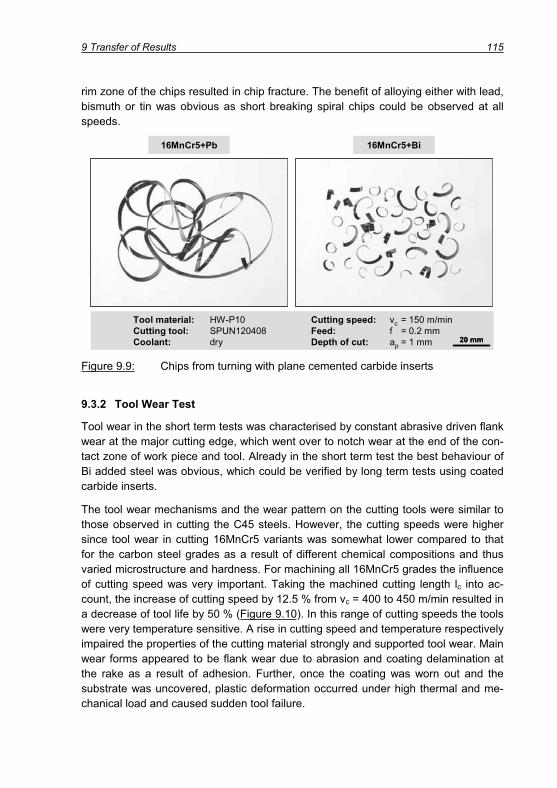
9 Transfer of Results 115
rim zone of the chips resulted in chip fracture. The benefit of alloying either with lead, bismuth or tin was obvious as short breaking spiral chips could be observed at all speeds.
16MnCr5+Bi
Tool material: HW-P10 Cutting speed: vc = 150 m/minCutting tool: SPUN120408 Feed: f = 0.2 mmCoolant: dry Depth of cut: ap = 1 mm
16MnCr5+Pb
20 mm
16MnCr5+Bi
Tool material: HW-P10 Cutting speed: vc = 150 m/minCutting tool: SPUN120408 Feed: f = 0.2 mmCoolant: dry Depth of cut: ap = 1 mm
16MnCr5+Pb
20 mm20 mm
Figure 9.9: Chips from turning with plane cemented carbide inserts
9.3.2 Tool Wear Test
Tool wear in the short term tests was characterised by constant abrasive driven flank wear at the major cutting edge, which went over to notch wear at the end of the con-tact zone of work piece and tool. Already in the short term test the best behaviour of Bi added steel was obvious, which could be verified by long term tests using coated carbide inserts.
The tool wear mechanisms and the wear pattern on the cutting tools were similar to those observed in cutting the C45 steels. However, the cutting speeds were higher since tool wear in cutting 16MnCr5 variants was somewhat lower compared to that for the carbon steel grades as a result of different chemical compositions and thus varied microstructure and hardness. For machining all 16MnCr5 grades the influence of cutting speed was very important. Taking the machined cutting length lc into ac-count, the increase of cutting speed by 12.5 % from vc = 400 to 450 m/min resulted in a decrease of tool life by 50 % (Figure 9.10). In this range of cutting speeds the tools were very temperature sensitive. A rise in cutting speed and temperature respectively impaired the properties of the cutting material strongly and supported tool wear. Main wear forms appeared to be flank wear due to abrasion and coating delamination at the rake as a result of adhesion. Further, once the coating was worn out and the substrate was uncovered, plastic deformation occurred under high thermal and me-chanical load and caused sudden tool failure.

116 9 Transfer of Results
0
50
100
150
200
250
300
350
400
0 1000 2000 3000 4000 5000 60000
50
100
150
200
250
300
350
400
0 1000 2000 3000 4000 5000 6000
0
50
100
150
200
250
300
350
400
Cutting length lc / m
Flan
k w
earV
BB
,C/ μ
m
Cutting length lc / m
Cutting time tc / min2.7 5.3 8 10.70 13.3
2.2 4.4 6.7 8.9 11.1 13.3Cutting time tc / min
vc = 375 m/min
vc = 450 m/min
Cutting Tool: CNMG120308Tool Material: HC-P25Feed: f = 0.25 mmDepth of cut: ap = 2 mmCoolant: dryMaterial:
2.5 5 7.5 10 12.5 15
vc = 400 m/min
0 0
16
Flan
k w
earV
BB
,C/ μ
m
16MnCr516MnCr5+Pb16MnCr5+Sn16MnCr+Bi
0
50
100
150
200
250
300
350
400
0 1000 2000 3000 4000 5000 60000
50
100
150
200
250
300
350
400
0 1000 2000 3000 4000 5000 6000
0
50
100
150
200
250
300
350
400
Cutting length lc / m
Flan
k w
earV
BB
,C/ μ
m
Cutting length lc / m
Cutting time tc / min2.7 5.3 8 10.70 13.3
2.2 4.4 6.7 8.9 11.1 13.3Cutting time tc / min
vc = 375 m/min
vc = 450 m/min
Cutting Tool: CNMG120308Tool Material: HC-P25Feed: f = 0.25 mmDepth of cut: ap = 2 mmCoolant: dryMaterial:
2.5 5 7.5 10 12.5 15
vc = 400 m/min
0 0
16
Flan
k w
earV
BB
,C/ μ
m
16MnCr516MnCr5+Pb16MnCr5+Sn16MnCr+Bi
Figure 9.10: Tool wear progression in machining different alloyed 16MnCr5 grades with coated CNMG120408 inserts (HC-P25)
At all applied cutting speeds it could be observed that in the area of linear tool wear development on one side leaded and Sn added steel and on the other side 16MnCr5 and the Bi added variant showed similar tool wear. However, all tested alternative grades led to an increase of tool life compared to 16MnCr5+Pb. Thereby the Bi added variant again gave the best performance. The overall low performance of the leaded steel regarding tool wear may be related to the chemical composition and the distribution of non-metallic inclusions. Since the aluminium content was higher for the leaded material, it stands to reason that hard aluminium silicates and aluminium ox-ides supported abrasive wear attack although the hardness of the material showed the lowest values. In addition, the strong tool wear in machining fine grained 16MnCr5+Pb and the very good performance of coarse grained 16MnCr5 has to be linked to the respective microstructure. ARENDT [AREN04] pointed out that coarse grained case carburising steels of the 16MnCr5 type showed a pronounced reduction of tool wear in turning compared to fine grained microstructures.

9 Transfer of Results 117
Merging the results from screening and tool wear testing it can be concluded that alloying 16MnCr5 with Bi is the best way to substitute for lead. The renunciation of lead and application of plain 16MnCr5 shows potential with regard to tool wear, but if chip breakage is important, this material is not recommended. Hence, the results from machining the 11SMn30 grades as well as the C45 steels are confirmed and in a way the transfer of the results seems to be valid.

118 10 Economical Assessment
10 Economical Assessment
The investigations presented in chapters 6 gave much information about the techno-logical potential of different alloyed steels against the background of a possible re-placement for lead in machining processes. Technological feasibility is a basis for economical success of cutting processes. Nevertheless, the cost of a machined component KF does not only depend on machining cost, which includes according to the following equation the set-up and non-productive time (tr and tn), the productive time (th), the machine and labour cost (KML) and the tool costs (KWT):
)Kt(KTttKt
mtKK WTwML
hhMLn
rMLF Equation 10.1
The cost of a machined component also depends on the expense for work piece ma-terial. In order to rate the difference in material cost, the price for leaded steel has to be taken as a basis.
The easiest way of setting lead aside is to use plain 11SMn30 steel. With regard to material cost this is a good solution as the price is about 10 % lower compared to leaded material. In contrast, the tin added steels are much more expensive when the annealing treatment described in chapter 4.1 is conducted. This special heat treat-ment process (500°C for 2 h) is time and consequently cost consuming. In addition, effort for handling and transportation comes along, which has to be accounted in the material costs. Thus, approaches to ensure grain boundary segregation of tin during the cooling down process from hot rolling is of substantial interest for this steel. Out of the investigated elements, the most expensive one is bismuth (Table 10.1). Cur-rently, its price amounts to the decuple of lead, whereas it has to be taken into ac-count that machinability enhancement can be achieved at lower bismuth amounts. In the present investigations on low carbon free cutting steels the Bi content (0.075 %) was only one quarter of the lead content (0.3 %). According to Table 10.1 this would implicate a rise of material cost by at most 7 EUR per tonne. Assuming a steel price of 10,000 EUR/t, this increase would be similar to 0.04 %.
Property Pb Sn Bi
Price per kg 0.7 – 1 EUR 3.5 – 6.5 EUR 6.5 – 9 EUR
Table 10.1: Raw material cost of alloying elements in 2005 [HAND06, META06]
Bismuth is only the 69th element in order of abundance in the Earth’s crust and is about twice as abundant as gold. World reserves of bismuth are usually based on bismuth content of lead resources because bismuth production is most often a by-product of processing lead ores; in China, bismuth production is a by-product of

10 Economical Assessment 119
tungsten and other metal ore processing. Bismuth minerals rarely occur in sufficient quantities to be mined as principal products. Only in two mines bismuth is produced from a bismuth ore. However, several bismuth-containing deposits are in varying stages of mining feasibility review [USGS05]. As a result of the supply and demand situation the bismuth price is believed to increase tremendously in the future. Hence, the cost for bismuth alloyed steel will exceed the before mentioned increase of about 0.5 % compared to leaded steel. Further, it should be kept in mind that bismuth low-ers hot ductility (see chapter 4). For this reason, the rolling of bismuth added steel might be impaired and therefore the steel making cost could increase.
In order to keep the costs for a machined part at a low level, the higher effort for ma-terial has to be compensated by a reduction in machining costs. Presuming machine and labour cost and set-up time to be unchangeable, specific importance is ascribed to tool costs, tool life, productive time, tool change time and non-productive time. Usually, lowest potential for cost reduction can be seen in tool costs as they cause only 3 – 5 % of the total cost [WERT04]. The tool life time has to be linked to the pro-ductive time. If tool life is increased, the cutting speed is probably going to be height-ened, which results in a reduction of productive time. Thus, the machining perform-ance of a work piece material is of substantial interest with regard to cost reduction. Within chapters 6 and 8 it could be shown that Bi added material showed the highest potential in respect of an increase of machining performance. In order to tap the full potential, coated cemented carbide inserts should be applied at cutting speeds, which are higher compared to conventional machining of leaded parts. Possibly, new machine tools may be necessary to provide high spindle speeds. Although the in-vestments for new machine tools are high, it has to be considered that beside the productive time also the remaining factors tool change time and non productive time may be decreased due to technological progress. Summarising, the material cost would increase but the machining cost would fall, which may result in lower total cost for a machined part.
Further, the change from wet to dry cutting implies a high potential regarding cost reduction. Not only can the expenditures for cutting fluid itself but also for the periph-ery be saved. Pumps, filters, exhausts and separators for cutting fluid application are no longer necessary. Further, effort for part cleaning can be reduced. Along the benefits respecting manufacturing costs, the change to dry cutting is furthermore an important step towards environmentally friendly manufacture.

120 11 Summary and Outlook
11 Summary and Outlook
Free cutting steels have been alloyed with lead for a long time in order to improve machinability. Although the lead content in steel is comparably low, leaded steels are under threat for environmental reasons. Alternatives have to be found as on long term lead is supposed to be banned from steels exceptionally. Hence, the objective of this work was to investigate suitable alternatives to approach the goal of lead sub-stitution and to enhance machinability of non-leaded steel.
A comprehensive description of properties, characteristics and functions of lead in cutting processes showed that the benefit mainly occurs due the low melting point of lead ( s, Pb = 327°C) and the fact that lead is not soluble in steel and distributed in sub microscopic size in the steel matrix. Based on this information alloying elements were chosen, which show similar characteristics to lead. Bismuth, tin and sulphur counted among the most promising elements. After a detailed description of six dif-ferent alloyed low carbon free cutting steels (11SMn30 type), five carbon steels (C45 type) and four case carburising steels (16MnCr5 type) a comprehensive machinabil-ity investigation was carried out. Thereby the results of machinability testing of leaded 11SMnPb30 steel were taken as a basis for comparison. A benefit analysis finally gave a transparent overview of the potential of each material in respect of the evaluation criteria process forces, surface quality, chip form and tool life.
11SMnPb30 particularly stood out in machining with uncoated carbide tools. Low process forces, high surface quality, desirable chip breakage and low tool wear char-acterised the machinability of leaded steel. Most important effects of lead were lubri-cating effects in primary and secondary deformation zone and the tendency to re-duce build up edge formation. Changing over to coated carbide tools obviously im-paired tool life, whereas the outstanding reduction of process forces was still present. Out of the non-leaded materials, 11SMn30+Bi turned out to be the best material, par-ticularly with respect to process forces, chip forms and surface quality. The wear be-haviour strongly depended on the tool material. Flank wear at uncoated carbide tools was a clear disadvantage of 11SMn30+Bi, whereas in cutting with coated tools this material was superior to all other tested grades. 11SMn30 gave best performance regarding process forces compared to the other lead free steels. Admittedly, tool wear and surface quality significantly depended on the applied tools. In cutting with coated inserts even better surface quality could be achieved than in machining leaded 11SMnPb30. Nevertheless, the clearest disadvantage appeared to be non sufficient chip breakage. Although the further rise of the sulphur content did not con-tribute to solve the chip form problem, overall it resulted in improved machinability for uncoated tools, whereas deterioration for coated tools could be detected. Compared to the other non-leaded grades, biggest advantage of 11SMn37 application were slightly lower process forces and high tool wear in machining with HW-P10 cemented carbide. Regarding both tin added materials, it could be observed that neither the low

11 Summary and Outlook 121
nor the high copper variant gave best performance regarding any machinability evaluation criteria. These materials were capable of bearing comparison with leaded steel in terms of surface quality when coated tools came into operation. Neverthe-less, poor chip fracturing was the major disadvantage of the tin added steels and par-ticularly when using the low copper variant problems regarding tool life occurred. It seems that this material is not suited for continuous operations like turning but possi-bly for interrupted cutting processes such as milling.
Overall, the investigations on low carbon free cutting steels (11SMn30 type) indicated that leaded steel was superior when using uncoated carbide tools, whereas 11SMn30+Bi turned out to be the best grade out of the non-leaded materials. Chang-ing over to coated inserts it became obvious that 11SMn30+Bi marked the best ma-chining performance. Thereby, dry cutting was preferable as the application of cutting fluid deteriorated tool life due to increase of mechanical wear attack. It could be shown that tin added material, which is claimed to be the best alternative to leaded steel, did not contribute to an enhancement of the machining performance of stan-dard lead free 11SMn30 steel. Cutting tests on different alloyed C45 and 16MnCr5 grades made clear that the results could be transferred to other materials and veri-fied the cognition that bismuth seems to be capable of substituting for lead and even of enhancing machinability, particularly when coated tools are used. Nevertheless, it has to be taken into account that the material price would rise the more bismuth is used as alloying element since the reserves of bismuth are comparably rare.
Within this work it could be demonstrated that out of the investigated variants, adding bismuth is the most promising approach towards lead renunciation in steels. How-ever, the continuation of research on the machining performance of bismuth alloyed steel is interesting as a further improvement of machinability seems reasonable. It should be clarified if the bismuth content has a significant influence on machinability. Possibly a changed amount even may contribute to an improvement of cutting with uncoated tools. The tribological and chemical interactions of bismuth added steel and cemented carbide have to be analysed in detail, wherefore a close cooperation with chemists and material scientists seems expediently. Nevertheless, when increasing the bismuth content attention has to be paid to the rollability of the steel material as the mentioned element impairs hot ductility. In addition, the role of tool coatings is an important topic as it has to be analysed if a change in the coating system results in varied cutting performance.
However, although the work on machinability enhancement seems to be an endless task, this work contributes to a clarification of the potentials arising by alloying with different elements and shows which alloying elements should be focus of future in-vestigations.

122 12 Literature
12 Literature
[2000/53] N.N.: Directive 2000/53/EC of the European Parliament and of the Council of 18 September 2000 on end-of-life vehicles, The Official Jour-nal of the European Communities, Luxemburg, 2000
[2000/60] N.N.: Directive 2000/60/EC of the European Parliament and of the Council of 23 October 2000 establishing a framework for Community action in the field of water policy, The Official Journal of the European Communities, Luxemburg, 2000
[2002/95] N.N.: Directive 2002/95/EC of the European Parliament and of the Council for the purpose of establishing the maximum concentration values for certain hazardous substances in electrical and electronic equipment, The Official Journal of the European Communities, Luxem-burg, August 19, 2005
[2003/108] N.N.: DIRECTIVE 2003/108/EC OF THE EUROPEAN PARLIAMENT AND OF THE COUNCIL of 8 December 2003 amending Directive 2002/96/EC on waste electrical and electronic equipment (WEEE), The Official Journal of the European Communities, Luxemburg, 2002
[4MAN06] N.N.: 4managers - Nutzwertanalyse, January 23, 2006: http://www.4managers.de/
[ABEY83] ABEYAMA, S.; KIMURA, A.; NAKAMURA, S.: The Influence of Cold Forging on Machinability of Low Alloyed Steels, Journal of Applied Metal Work-ing, Vol. 2, No. 4, 1983
[ABOR68] ABORN, R. H.: The role of Metallurgy, particularly Bismuth, Selenium and Tellurium in the Machinability of Steel, American Smelting and Re-fining Company, New York, 1968
[ABOR77] ABORN, R. H.: Role of Additives in Machinability, International Sympo-sium on Influence of Metallurgy of Steel, Tokyo, Sept. 26 – 28, 1977
[AHMA89] AHMAD, M. M.; DERRICOTT, R. T.; DRAPER, W. A.: A Photoelastic Analy-sis of the stress in Double Rake Cutting Tool, International Journal of Machine Tools and Manufacture, Vol. 29/2, 1989, pp. 185 – 195
[ALBR60] ALBRECHT, P.: New Developments in the Theory of Metal-Cutting Proc-ess, Part I, The Ploughing Process in Metal Cutting, Trans. ASME 82, 1960, pp. 348 – 358
[ALLU06] N.N.: ALLUM - das Informationsangebot zu Allergie, Umwelt und Ge-sundheit, January 16, 2006:
http://www.allum.de/index.php?mod=noxe&n_id=75

12 Literature 123
[ALTE58] ALTENWERTH, F.: Abrieb und Phasengrenzflächenreaktionen bei der Zerspanung an den Kontaktzonen der Werkzeuge und ihre Abhängig-keit von der Zusammensetzung und dem Gefügeaufbau der Hartmetall-Legierung, Dissertation, RWTH Aachen, 1958
[ALTF02] N.N.: Federal Law Gazette I number 41, June 28, 2002, p. 2199 (End-of-life Vehicle Act - AltfahrzeugG)
[ANDE71] ANDERS, A.: Wirtschaftliche Zerspanung von Stahl, Zeitung für wirt-schaftliche Fertigung, 66, Nr. 11, 1971, pp. 554 – 558
[APPL89] APPLE, C. A.: The Relationship between Inclusions and the Machinabil-ity of Steel, Mechanical Working and Steel Processing Conference Proceedings, 1989, pp. 415 – 426
[AREN04] ARENDT, C.: Angepasste Stähle zur effektiven und umweltgerechten Drehbearbeitung, Dissertation, Universität Hannover, 2004
[BART88] BARTSCH, S.: Verschleiß von Aluminiumoxidkeramik-Schneidstoffen unter stationärer Belastung, Dissertation, Universität Hannover, 1988
[BDSV01] N.N.: Stahlschrott – ein “grüner“ Rohstoff, Bundesvereinigung Deut-scher Stahlrecyling- und Entsorgungsunternehmen BDSV-Presentation, ENVITEC, Düsseldorf 2001: http://www.bdsv.de/info/jata/01_brosc.phpv
[BECK77] BECKER, H.; HOFF, H.: Einfluss des Mangan- und Bleigehaltes auf die Zerspanbarkeit von unberuhigtem Automatenstahl, Stahl und Eisen 77, 1957, pp. 1215 – 1220
[BEIT90] BEITZ, W.; KÜTTNER, K.-H.: Dubbel, Taschenbuch für den Maschinen-bau, 17. Auflage, Springer-Verlag, Berlin/Heidelberg, 1990
[BENE61] BENDEDIC, S.: Bleihaltige Baustähle helfen Bearbeitungszeiten verkür-zen, Die Maschine 15/9, 1961, pp. 45 – 46
[BERN01] BERNSMANN, G., BLEYMEHL, M.; EHL, R.; HASSLER, A.: The making of free cutting steels with additions of lead, bismuth, tellur, selenium and tin, Stahl und Eisen 121 Nr. 2, 2001
[BERS71] BERSCH, B.: Wirkung von Blei auf die Zerspanbarkeit von Automaten-stahl, Dissertation, RWTH Aachen, 1971
[BERT95] BETRAND, C.; COUSO, J. M.: Market Introduction of Improved Ma-chinability Engineering Steels Neither Toxicity Nor Environmental Ef-fects, ECSC contract VA-940012, 1995
[BERT98] BETRAND, C.; DE SOLAR, M.: Can We Survive Without Leaded Steels? 4th International Conference on Behaviour of Materials in Machining, Stratford upon Avon, 1995
124 12 Literature
[BHAT82] BHATTACHARYA, D.: Effects of Metal Induced Embittlement in Free Ma-chining Steels, The Metallugical Society of AIME, Embrittlement by Liq-uid Solidmetals, 1982, pp. 367 - 398
[BICK63] BICKEL, E.: Die metallischen Werkstoffe des Maschinenbaus, Berlin, Springer-Verlag, 1963
[BLAC84] BLACH,J.; ZAHUMENSKY, P.: Some Questions Concerning the Cohesion Strength of Steels, Metallic Materials 1994, 32, pp. 162 – 168
[BLETT90] BLETTON, O.; DUET, R.; PEDARRE, P.: Influence of Oxide Nature in the Machinability of 316L Stainless Steels, Wear 139, 1990, pp. 179 – 193
[BMU05] N.N.: Federal Ministry for Environment, Nature Conservation and Nu-clear Safety (BMU), December 11, 2005: http://www.bmu.de/english/waste_management/doc/3443.php
[BMU06] N.N.: Federal Ministry for Environment, Nature Conservation and Nu-clear Safety (BMU), January, 2006:
http://www.umweltbundesamt.de/uba-info-daten/daten/blei.htm
[BOEH84] BÖHNKE, K.; ENGINEER, S.; FLEISCHER, H.-J.; SCHÜLER, V.: Der Einfluß von Schwefel, Schwefel und Tellur sowie Schwefel und Kalzium auf die Spanbarkeit und die mechanisch-technischen Eigenschaften einiger Edelbaustähle in unterschiedlichen Gefügezuständen, Thyssen Edel-stahl Technische Berichte, 10. Band, Heft 2, 1984, pp. 18 - 173
[BOWD54] BOWDEN, F. P.; TABOR, O.: The Friction and Lubrication of Solids, Ox-ford University Press, London, 1954
[BSW05] N.N.: Umwelterklärung 2005 der Badischen Stahlwerke GmbH: http://www.bsw-kehl.de (February 11, 2006)
[BUDA68] BUDA, J.; VASILKO, K.; STRANAVA, J.: Neue Methoden der Spanwurzel-gewinnung zur Untersuchung des Schneidvorganges. Industrie-Anzeiger, Jahrg. 90, Nr. 5, 1968, pp. 24 – 27
[CHAN94] CHANDRASEKARAN, H.; JOHANSSON, J. O.: Chip Flow and Notch Wear Mechanisms during the Machining of High Austenitic Stainless Steels,Annals of the CIRP 43 Vol 1, 1994
[CHIL89] CHILDS, T. H. C.; MAHDI, M. I.: On the Stress Distribution Between the Chip and Tool During Metal Turning, Annals of the CIRP Vol. 38/1, 1989
[CHIL90] CHILDS, T. H. C.; MAEKAWAS, K.: Computer-Aided Simulation and Ex-perimental Studies of Chip Flow and Tool Wear in the Turning of Low Alloy Steels by Cemented Carbide Tools, Wear 139, 1990, pp. 235 – 250,
12 Literature 125
[CLIN88] CLINE, R. S.; BHATTACHARAYA, D.: Microalloyed Steels with Enhanced Machinability, Mechanical Working and Steel Processing Proceedings, 1988, pp. 97 – 102
[DAHL93] DAHL, W.: Eigenschaften und Anwendungen von Stählen, Bd. 2, Aa-chen, Verl. der Augustinus-Buchh., 1993
[DAMA90] DAMARITÜRK, H. S.: Temperaturen und Wirkmechanismen beim Hoch-geschwindigkeitsfräsen von Stahl, Dissertation, TU Darmstadt, 1990
[DEAR01A] DEARDO, A. J.; GARCIA, C. I.: Free-machining steels containing tin anti-mony and/or arsenic, U. S. Patent Nr. 6200395, 2001
[DEAR01B] DEARDO, A. J.; GARCIA, C. I.: Medium carbon steels and low alloy steels with enhanced machinability, U. S. Patent Nr. 6206983, March 2001
[DEAR99A] DEARDO, A. J.; GARCIA, C. I.: Tin-bearing free-machining steel, Interna-tional Patent Application No. WO 99/25891, University of Pittsburgh, 1999
[DEAR99B] DEARDO, A. J.; GARCIA, C. I.: Tin-bearing free-machining steel, U. S. Patent Nr. 5,61747, 1999
[DECH77] DE CHIFFFRE, L.: International Journal of Machine Tool Design Re-search, 1977, p. 225
[DENK92] DENKENA, B.: Verschleißverhalten von Schneidkeramik bei instationärer Belastung, Dissertation, Universität Hannover, 1992
[DETE99] DETERS, L.; BOSSE, H.: Wärmeeindringzahlen von PVD-Verchleiß-Schutzschichten, Tagungsband Reibung, Schmierung und Verschleiß – Tribologie Fachtagung 27.9.-29.9., Göttingen, 1999
[DOMK86] DOMKE, W.: Werkstoffkunde und Werkstoffprüfung, Cornelsen Verlag, Berlin, 1986
[DREß64] DREßLER, H. W.: Einflussgrößen auf die Zerspanbarkeit von Automa-tenstahl, Dissertation, RWTH Aachen, 1964
[DROE87] DROESE, J.: Titannitrid beschichtete HSS-Spiralbohrer - Leistungsfähig-keit und Verschleißmechanismen, Dissertation, RWTH Aachen, 1987
[EN10277] DIN EN 10277: Bright steel products – Technical delivery conditions – Part 3: free cutting steels; German version 10277-3, 1999
[ENIR06] N.N.: e-niro – Lexikon der Fachbegriffe, January 26, 2006: http://www.e-niro.de/exec.php/lexikon.htm
[FAUL98] FAULRING, G. M.: Inclusion Modification in Semi-Killed Steels, Electric Furnace Conference Proceedings, New Orleans, 1998, pp. 87 – 98

126 12 Literature
[FINN90] FINN, M. E.: Factors Influencing Machining and Their Controls, Proceed-ings of ASM International Conference and Workshop, Cincinnati, Ohio, 1990, pp. 123 – 135
[FLEI85] FLEISCHER, H.-J.; ENGINEER, S.; SCHÜLER, V.: Entwicklungen bei Edel-stählen für Schmiedeteile, VDI-Tagung – Das Schmiedeteil als Kon-struktionselement, VDI-Berichte 554, 1987, pp. 55 – 65
[FREY87] FREY, H.; KIENEL, G.: Dünnschichttechnologie. Düsseldorf, VDI-Verlag, 1987
[FRÖH75] FRÖHLKE, M.: Untersuchung über den Einfluss nichtmetallischer Ein-schlüsse auf die Zerspanbarkeit kohlenstoffarmer, schwefelhaltiger Au-tomatenstähle, Dissertation, RWTH Aachen, 1975
[GARC02] GARCIA, C.I.; HUA, M.; DEARDO, A. J.: Application of Grain Boundary Engineering in the Development of “Green Steel”, Conference Papers of 5th International Conference on Behaviour of Material in Machining, 12 – 13 November 2002, Chester, U.K., pp. 214 – 226
[GARC03] GARCIA, C.I.; HUA, M.; MILLER, M. K.; DEARDO, A. J.: Application of Grain Boundary Engineering in Lead-free “Green Steel”, ISIJ Interna-tional, Vol. 43, No. 12, 2003, pp. 2023 – 2027
[GARC98] GARCIA, C. I.; GAO, W.; DEARDO, A. J.: Hot Ductility Behavior of Leaded Free Machining Steels, Basic Metals Processing Research Institute, Internal Report, University of Pittsburgh, 1998
[GARV66] GARVEY, T. M.; TATA, H. J.: Machinability and Metallurgy of Resulfurized Low-carbon-Free-Machining Stainless Steels, Amer. Soc. Tool and Mfg. Engs, Paper EM66-180, 1966
[GERS97] GERSCHWILER, K.: Untersuchungen zum Verschleißverhalten von Cer-mets beim Drehen und Fräsen, Dissertation, RWTH Aachen, 1997
[GEY05] GEY, C.: Beeinflussung der Zerspanung durch Schichteigenschaften, Seminar – Werkzeuge für die Zerspanung, IFW Hannover, 16. – 17.02. 2005
[GORD67] GORDON, M. B.: The Applicability of the Binominal Law to the Process of Friction in the Cutting of Metals, Wear 10, 1967, pp. 274 – 290
[GRAB89] GRABKE, H. J.: Surface and Grain Boundary Segregation on and in Iron and Steels, ISIJ International, Vol. 229, No. 7, 1989, pp. 529 – 538
[GRAH33] GRAHAM, H. W.: What the User Should Know About Free Cutting Steels, Iron Age 131, 1933

12 Literature 127
[GRAH94] GRAHAM, D. T.: New Machining Steel Developments at UES Steels, 3rd
International Conference on the Behaviour of Materials in Machining, 15.-17.11. 1994, University of Warwick, UK.: The Institute of Materials, S. 78 - 103
[GROT04] GROTE, K.-H.; FELDHUSEN, J.: Dubbel Taschenbuch für den Maschi-nenbau, Berlin Heidelberg, Springer-Verlag, 2001
[GRZE04] GRZESIK, W.; BARTOSZUK, M.; NIESLONY, P.: Finite difference analysis of the thermal behaviour of coated tools in orthogonal cutting of steels, International Journal of Machine Tools & Manufacturing 44, 2004, pp. 1451 – 1462
[HAMA96] HAMANN, J. C.; GROLLEAU, V.; LE MAITRE, F.: Machinability Improve-ment of Steels at High Cutting Speeds – Study of Tool/Work Material Interaction, Annals of the CIRP, 1996, pp. 87 – 92
[HAND06] N.N.: Handelsblatt Kursabfrage, January 25, 2006: http://www.handelsblatt.de/
[HODO00] Hodowany, J.; Ravichandran, G.; Rosakis, A. J.; Rosakis, P.: Parti-tion of Plastic Work into Heat and Stored Energy in Metals; Experimen-tal Mechanics, Vol. 40-2, 2000
[HOPP04] HOPPE, S.: Experimental and numerical analysis of chip formation in metal cutting, Dissertation, RWTH Aachen, 2004
[HOVI73] HOVIGA, H. J.: A Study of the Factor influencing the Roughness in Cut-ting Direction, Annals of the CIRP 21, 1973
[HUCH93] HUCHTEMANN, B.; ENGINEER S. UND SCHÜLER V.: Zum Einfluss von Schwefel, Calcium und Tellur auf die Spanbarkeit und die mechanisch- technologischen Eigenschaften von Edelbaustählen, DGM-Fortbildungs-Seminar, Institut für Fertigungstechnik und spanende Werkzeugmaschinen, Hannover, 1993
[HUCH98] HUCHTEMANN, B.; WULFMEIER, E.: Begleitelemente im Edelstählen und ihr Einfluß auf die Verarbeitungseigenschaften, Stahl und Eisen 118, Nr. 11, 1998, pp. 129 – 135
[ISO3685] ISO 3685: Tool-life testing with single-point turning tools, 2nd edition, Organisation for Standardization, 1993
[JIAN94] JIANG, L.; HÄNNINEN, H.: Machinability of Steel, A Review, Laboratory of Engineering Materials, Helsinki University of Technology, 1994
[JIAN96] JIANG, L.; CUI, K.; HÄNNINEN, H.: Effects of Composition, Shape Factor and Area Fraction of Sulfide Inclusions on Machinability of Resulfurized Free-Machining Steel, Journal of Materials Processing Technology, Vol. 44, 1996

128 12 Literature
[KAEM69] KÄMMER, K.: Zerspanungsuntersuchungen an Automatenstählen zur Verbesserung der Maschinenausnutzung und der Werkzeugstandzei-ten, Zeitschrift für wirtschaftliche Fertigung 64/6, 1969, pp. 286 – 295
[KAMM92] KAMMERMEIER, D.: Charakterisierung von binären und ternären Hart-stoffschichten anhand von Simulations- und Zerspanuntersuchungen,Dissertation, RWTH Aachen, 1992
[KATA06] N.N.: KATALYSE Umweltlexikon, January 22, 2006:
http://www.umweltlexikon-online.de
[KATO72] KATO, S.; YAMAGUCHI, K.; YAMADA, M.: Stress Distribution at the Inter-face Betweeen Tool and Chip in Machining, Journal of Engineering for Industry 94, 1972, pp. 683 – 689
[KATT57] KATTWINKEL, W.: Untersuchungen an Schneiden spanender Werkzeuge mit Hilfe der Spannungsoptik, Industrieanzeiger 36, 1957, pp. 29 – 36
[KIEN52] KIENZLE, O.: Die Bestimmung von Kräften und Leistungen an spanen-den Werkzeugen und Werkzeugmaschinen, Z.VDI Jg. 94 H. 11/12, 1952, pp. 299 – 304
[KISH76] KISHI, K.; EDA, H.: The lubrication and deformation mechanism of MnTe, MnS, MnSe and Pb inclusions in various steels during wear and cutting processes, Wear 38, 1976, pp. 29 – 42
[KLAU65] KLAUS, F.; KÖNIG, W.; LÜCKERATH, W.; SIEBEL, H.: Stand der Kenntnis über die Zerspanbarkeit der Stähle, Stahl und Eisen 85/25, 1965, pp. 1669 – 1689
[KLOC04] KLOCKE, F; ESSEL, I.: Basics of HPC and Mechanical and Thermal Characteristics, Proceedings of the CIRP International Conference on High Performance Cutting, Aachen, 2004
[KLOC96] KLOCKE, F.; ZINKANN, V.: Versteckte Potentiale im Stahlwerkstoff nut-zen, Industrieanzeiger 9/96, 1996, pp. 58 – 62
[KLOC97] KLOCKE, F.; KRIEG, T.; ZINKANN, V.: Beeinflussung der Kontaktbedin-gungen beim Zerspanen durch nichtmetallische Einschlüsse im Stahl,Stahl und Eisen 177, 1997, pp. 61 – 66
[KLOC98] KLOCKE, F.; ZINKANN, V.; KRIEG, T.: Trockenbearbeitung durch calcium-behandelte Stähle, VDI-Z 140, 1998, pp. 44 – 49
[KLUF79] KLUFT, W. ET AL.: Present Knowledge of Chip Control, Annals of the CIRP Vol. 28(2), 1979
12 Literature 129
[KOEN02] KÖNIG, W.; KLOCKE, F.: Fertigungsverfahren 1 Drehen, Fräsen, Bohren,Berlin Heidelberg, Springer-Verlag, 2002
[KOEN65] KÖNIG, W.: Der Einfluß nichtmetallischer Einschlüsse auf die Zerspan-barkeit von unlegierten Baustählen, Teil 1-3, Industrie-Anzeiger, 87, Nr. 26 (pp. 61 - 68), 43 (pp. 131 - 136) und 51 (pp. 165 - 170), 1965
[KOEN75] KÖNIG, W.; SCHEMMEL, U.: Untersuchung moderner Schneidstoffe - Be-anspruchungsgerechte Anwendung sowie Verschleißursachen, For-schungsber. Nr. 1349 des Lds. Nordrh.-Westf., Westdeutscher Verlag, Köln, Opladen, 1975
[KOEN82] KÖNIG, W.; ESSEL, K.; WITTE, L.: Spezifische Schnittkraftwerte für die Zerspanung metallischer Werkstoffe, Verein Deutscher Eisenhüttenleu-te, Verlag Stahleisen mbH, Düsseldorf, 1982
[KREK51] KREKELER, K.: Zerspanbarkeit der metallischen und nichtmetallischen Werkstoffe, Springer- Verlag, Berlin, 1951
[KRIE00] KRIEG, T: Eigenschaftsprofile von PVD-Werkzeugbeschichtungen für den Einsatz von umweltgerechte Kühlschmierstoff beim Drehen und Bohren von Stahlwerkstoffen, Dissertation, RWTH Aachen, 2000
[KRON54] KRONENBERG, M.: Grundzüge der Zerspanungslehre, Berlin, Springer-Verlag, 1954
[KTF06] N.N.: KTF Split – Faculty of Chemical Technology, January 16, 2006: http://www.ktf-split.hr/periodni/en/pb.html
[LAUR99] N.N.: http://www.laurelsteel.com/greensteel.html (December 10, 2005)
[LDAI05] N.N.: http://www.ldaint.org (December 10, 2005)
[LESK86] LESKOVAR, P.; GRUM, J.: Metallurgical Aspects of Machining, Annals of the CIRP, Vol. 35, 1986
[LEWI58] LEWIS, K. G.: Property of Free Machining Effects of Sulphur and Lead,Iron and Steel, 1958, pp. 133 – 140
[LEWI85] N.N.: U.S. Environmental Protection Agency - Lead Poisoning: A His-torical Perspective, EPA Journal, 1985, January 22, 2006:
http://www.epa.gov/history/topics/perspect/lead.htm
[LOLA49] LOLADSE, T. N.: Über einige Erscheinungen bei der Spanbildung. Arbei-ten des Grusinischen Polytechnischen S. M. Kirow-Instituts, Nr. 20, 1949

130 12 Literature
[LUCZ99] LUCZAK, H.; EVERSHEIM, W.: Produktionsplanung und Steuerung – Grundlagen, Gestaltung und Konzepte, Springer-Verlag, Berlin Heidel-berg, 1999
[LUTZ68] LUTZE, H.-G.: Ein Beitrag zur Ermittlung der an der Freifläche spanen-der Werkzeuge – insbesondere am Drehmeißel im freien Schnitt - auf-tretenden Kräfte und Spannungen, Dissertation, TH Karl-Marx-Stadt, 1968
[MARS70] MARSTON, G. J.; MURRAY, J. D.: Machinability of Low Carbon Free Cut-ting Steel, J. Iron and Steel Institute, 1970, pp. 568 – 575
[MERC50] MERCHANT, M. E.: Metal Cutting Research – Theory and Application,Machining-theory and Practise ASM Cleveland, Ohio, 1950, pp. 5 – 44
[META06] N.N.: http://www.metalprices.com (January 16, 2006)
[MEYE63] MEYER, K. F.: Vorschub- und Rückkräfte beim Drehen mit Hartmetall-werkzeugen, Dissertation, RWTH Aachen, 1963
[MILO83] MILOVIC, R.; WISE, L. H.; SMART, E. F.: The Effect of Lead on Machining of Low Carbon Steels with TiN Coated Tools, Annals of the CIRP Vol. 32/1, 1983
[MINT99] MINTZ, B.: The Influence of Composition on the Hot Ductility of Steels and to the Problem of Transverse Cracking, ISIJ International, Vol. 39, No. 9, 1999, pp. 883 – 855
[MUEL01] MÜLLER, B.; RENZ, U.: Development of a fast fiber-optic two-color py-rometer for the temperature measurement of surfaces with varying emissivities, Review of Scientific Instruments, American Institute of Physics, Vol. 72, No. 8, 2001, pp. 3366 – 3374
[MUEL02] MÜLLER, B.; RENZ, U.: Thermographic measurements of high-speed metal cutting process, Proceedings of SPIE, Thermosense XXVI, Or-lando, 2002, pp. 126 – 134
[MUEL03] MÜLLER, B.; RENZ, U.: Thermal Analysis of a High-Speed Metal Cutting Process, The 6th ASME-JSME Thermal Engineering Joint Conference, March 16 – 20, 2003
[MUEL04] MÜLLER, B.: Thermische Analyse des Zerspanens metallischer Werk-stoffe mit hohen Schnittgeschwindigkeiten, Dissertation, RWTH Aa-chen, 2004
[NAGA97] NAGASAKI, C.; KIHARA, J.: Effect of Copper and tin on Hot Ductility of Ultra- low and 0, 2 % carbon Steels, ISIJ International, Vol. 37, Nr. 5, 1997, pp. 523 – 530

12 Literature 131
[NAKA68] NAKAYAMA, K.; TAMURA, K.: Size effect in metal cutting force. Transac-tions of the AMSE, J. Eng. Ind., 1968/90, pp. 119 – 126
[NAYL76] NAYLOR, D. J.; LIEWELLYN, D. T.; KEANE, D. M.: Control of Machinability in Medium-Carbon-Steels, Metals Technology, 1976
[NNA] N.N.: Stahl-Eisen-Prüfblatt 1160-1169: Allgemeines und Grundbegriffe,Verlag Stahleisen mbH, Düsseldorf
[NORD90] NORDGREN, A.; MELANDER, A.: Tool Wear and Inclusion Behaviour Dur-ing Turning of a Clacium-treated Quenched and Tempering Steel using Coated Cemented Carbide Tools, Wear 139, 1990, pp. 209 – 223
[NRCL06] N.N.: NRCLP - National Referral Centre for Lead Poisoning in India, January, 2006: http://www.leadpoison.net
[OECD04] N.N.: Directorate for Science, Technology and Industry - Recent Steel Market Developments, prepared fort he OECD Special Meeting at High Level on Steel Issues, June 26 – 28, 2004
[PADU91] PADUCH, J.: Der Einfluß des Zusatzes von Calcium auf die Natur der nichtmetallischen Einschlüsse und best. Eigenschaften von Stahl,Prace I M 1-2, 1991
[PAJU91] PAJU, M.: Einfluss nichtmetallischer Einschlüsse auf die Zerspanbarkeit niedriglegierter Stähle, Werkstoffgefüge und Zerspanung, Fortbil-dungsseminar DGM und des IWF, Universität Hannover, 25. – 26.2.1991, pp. 2 – 22
[PAUD54] PAUDRAT, A.: Influence du souffre sur l’usinage des acierrs, en ce qui concerne la vitesse de coupe et l’usure des outils. La Génie Civil, 131, 1954, pp. 433 – 434
[PAUD54A] PAUDRAT, A.: Théorie relative à l’influence des elements et composes hexagonaux dans les ensembles polycristallins. Métaux Corrosion In-dusties, 29, 1954, pp. 315 – 334
[PEKE74] PEKELHARING, A. I.: Build-Up Edge (BUE): Is the mechanism under-stood? Annals of the CIRP Vol. 23/2, 1974, pp. 207 – 211
[PICK89] PICKERING, F. B.: Some Effects of Non-Metallic Inclusions on the Prop-erties of Steels, Mechanical Working and Steel Processing Proceed-ings, 1989, pp. 381 – 401
[PRAY41] PRAY, H.; PEOPLES, R. S.; FINK, F.W.: Additions of Bismuth for Produc-ing Free- Machining Stainless Steels, Proc. ASTM 41, 1941 und U.S. Patent 2,273,731, 1947

132 12 Literature
[PRIM69] PRIMUS, I. F.: Beitrag zur Kenntnis der Spannungsverteilungen in den Kontaktzonen von Drehwerkzeugen, Dissertation, RWTH Aachen, 1969
[QI00] QI, H. S.; MILLS, B.: Formation of a transfer layer at the tool-chip inter-face during machining, Wear 245, 2000, pp. 136 – 147
[QI96] QI, H. S.; MILLS, B.; HAO, C. S.; GUO, C. S.: An Investigation on the For-mation of Adherent Layer on a Cutting Tool, IMEC, 1996
[RAMA77] RAMALING, S.; BASU, K.; MALKIN, S.: Deformation Index of MnS- Inclu-sions in Resulphurised and Leaded Steels. Materials and Science En-gineering, 29, Lausanne: Elsevier Seqouia S. A., 1977, pp. 117-121
[RAMU96] RAMANUJACHAR, K.; SUBRAMANIAN, S. V.: Micromechansims of tool wear in machining free cutting steels, Wear 197, 1996
[ROLL65] ROLLASON, E. C.: Metallurgical Research on Machining at the University of Birmingham, The Iron and Steel Institute – Conference on Ma-chinability, October 4 – 6, 1965, pp. 67 – 72
[RUEB11] RÜBEL, W.: DRP 254 865 , 7. Juni 1911
[SALM83] SALMAN, H.; SCHOLZE, H.: Keramik, 2. Teil: Keramische Werkstoffe, Springer-Verlag, Heidelberg, 1983
[SAND00] SANDER, K.; LOHSE, J.; PIRNTKE, U.: Heavy Metals in Vehicles, Report, Ökopol – Insitut für Ökologie und Politik GmbH, Hamburg, 2000
[SCHE88] SCHEDLER, W.: Hartmetall für den Praktiker. Aufbau, Herstellung, Ei-genschaften und industrielle Anwendung einer modernen Werkstoff-gruppe, Plansee Tizit GmbH, VDI-Verlag, Düsseldorf, 1988
[SCHR43] SCHRADER, H.: Leistungssteigerung bei spanabhebender Bearbeitung durch Bleizusatz zum Stahl, Archiv für das Eisenhüttenwesen, 17, 1943, pp. 65 – 76
[SCHU06] N.N.: Fa. Schütte – Drehautomaten: http://www.schuette.de (February 11, 2006)
[SEIL06] SEIL, T.: Naturwissenschaftliches Arbeiten, January, 2006: http://www.seilnacht.com/Lexikon/82Blei.htm
[SHAW56] SHAW, M. C.: The Role of Friction in Deforming Processing, Transac-tions of the ASME 78, 1956, pp. 1649 – 1657
[SHAW60] SHAW, M. C.; BER, A.; MAMIR, P. A.: Friction Characteristics of Sliding Surfaces undergoing Subsurface Plastic Flow, Transactions of the ASME, 1960, pp. 342 – 346

12 Literature 133
[SHAW61] SHAW, M. C.; USUI, E.; SMITH, P. A.: Free Machining Steel I-III: Cutting Forces, Surface Finish and Chip Formation, Trans ASME, 83, 1961
[SHAW63] SHAW, M. C.: The Role of the Friction in Deforming Processing, Wear 6, 1963 2, pp. 140 – 158
[SIDE05] N.N.: http://www.sidech.be
[SOKO55] SOKOLOWSI, A. P.: Präzision in der Metallbearbeitung – Mittel und Wege zur Steigerung der Bearbeitungsgenauigkeit in der spanenden For-mung, S. 166-170, Berlin, VEB Verlag Technik, 1955
[SOME01] SOMEKAWA, M.; KAISO, M.; MATSUSHIMA, Y.: Free Cutting Non-lead Steels, Kobelco Technologie Review Nr. 24, 2001
[SPAA67] SPAANS, C.: An Exact Method to Determine the Force on the Clearance Plane, Annals of the CIRP, Vol. 15, 1967 , pp. 463 – 469
[SPAA71] SPAANS, C: The Fundamentals of Three-Dimensional Chip Curl, Chip Breakage and Chip Control, Doctor Dissertation, Laboratory for Produc-tion Engineering, Delft, 1971
[SPEN62] SPENCER, R. C., NAGELL, C. D.; RICHMOND, R.: How Tellurium affects Machinability of Steel, Metall Progress 82, 1962
[STAH06] N.N.: Internet Portal des Stahlzentrums Düsseldorf, January 26, 2006: http://www.stahl-online.de
[STOL63] STOLOFF, N. S.; JOHNSTON, T. L.: Crack propagation in a liquid metal environment, Acta Metallurgica, Vol 11, 1963, pp. 251 – 256
[SUBR03] SUBRAMANIAN, S.V.; ZHU, G.; ZHANG, X.; URLAU, U.; ROELOFS, H.: De-sign of inclusion engineered steel for high speed machining. 4th Inter-national Conference on Metal Cutting and High Speed Machining, Darmstadt 19.-21.03.03, 2003
[SUBR96] SUBRAMANIAN, S.V.; RAMANUJACHAR, K.: Strategies to Replace Lead in Free-Cutting Steels, 37th MWSP Conf., ISS, Vol. XXXIII, 1996, pp.341 – 353
[SUTT03] SUTTER, G.; FAURE, L.; MOLINARI, A.; RANC, N.: An experimental tech-nique for the measurement of temperature fields for the orthogonal cut-ting in high speed machining, International Journal of Machine Tools & Manufacture, 43, 2003, pp. 671 – 678
[TAKE64] TAKEYAMA, H.; USUI, E.: The Effect of Tool/Chip Contact Area in Metal Cutting, Transactions of the ASME, 75, 1953, pp. 273 – 283
[THIE99] THIELE, J.D. ET AL.: Effect of cutting edge geometry and work piece hardness on surface generation in the finish hard turning of AISI52100

134 12 Literature
steel, J. Mat. Proc. Tech. 94, 1999, pp. 216 – 226
[THOM62] THOMSEN, E.G.: Prediction of Forces and Energy in Metal Cutting, Jour-nal of the Institution of the Production Engineers, 1962
[THOM63] THOMSEN, E.G.; SCHALLER, E. DOHMEN, H.G.: Anwendung der Plastizi-tätsmechanik auf den Zerspanvorgang, Industrie-Anzeiger 46, 1963, pp. 967 – 974
[TOEN78] TÖNSHOFF, H. K., WARNECKE, G.: Über die Zerspanbarkeit von Stahl,VDI-Z 120 Nr. 7, 1978, pp. 311 – 318
[TOEN89] TÖNSHOFF, H. K.; KAESTNER, W.; SCHNADT, R.: Metallurgische Auswir-kungen der Calciumbehandlung von Stahlschmelzen auf die Bearbeit-barkeit, Stahl und Eisen 109, 1989, pp. 45 – 54
[TOEN95] TÖNSHOFF, H. K.: Spanen, Springer-Verlag, Heidelberg, 1995
[TOEN98] TÖNSHOFF, H. K., BERTHOLD, O.; ARENDT C.: Zerspanbarkeit mikrolegier-ter Stähle, DGM Seminar „Werkstoffgefüge und Zerspanung“, Hanno-ver Mai 1998
[TOWN95] TOWNSHEND, A.: Encyclopaedia of Analytical Science, London, Aca-demic Press, 1995
[TREN65] TRENT, E. M.: The Relationship between Machinability and Tool Wear,The Iron and Steel Institute – Conference on Machinability, October 4 – 6, 1965, pp. 31 – 36
[TROU33] TROUP, G. B.: Metallurgical Influence on Machinability of Free-Machining-Steel, Automatic Machining 27, 1966, pp. 66 – 73
[UKST98] N.N.: UK Steel - Briefing on End-of-life Vehicles Directive, 1998, Janu-ary, 2006: http://www.uksteel.org.uk/elv.htm
[UMWE06] N.N.: Umwelt unter einem D,A,CH, January 22nd, 2006: http://www.umweltdatenbank.de/lexikon/blei.htm
[USGS05] N.N.: Mineral Commodity Summaries, U.S. Geological Survey, Jan. 2005:http://minerals.usgs.gov/minerals/ (January, 2006)
[USUI60] USUI, E.; TAKEYAMA, H.: A Photoelastic Analysis of Machining Stress,International Journal of Machine Tools and Manufacture 11, 1960, pp. 303 – 308
[UWSP06] N.N.: University of Wisconsin Stevens Point, January, 2006: http://www.uwsp.edu/geo/courses/geog100/Lead-InEnv.htm

12 Literature 135
[VDA05] N.N.: Annual Report 2005 of the VDA (Verband der Automobilindus-trie), December 13, 2005: http://www.vda.de/en/service/jahresbericht/auto2005/umwelt/u_28.html
[VDEH94] N.N.: Werkstoffkunde Stahl, Verein Dt. Eisenhüttenleute (VDEH), Ber-lin, Springer-Verlag, 1984
[VICT56] VICTOR, H.: Beitrag zur Kenntnis der Schnittkräfte beim Drehen, Hobeln und Bohren, Dissertation, TH Hannover, 1956
[VIER55A] VIEREGGE, G.: Wärmequellen des Zerspanvorgangs, Warmzerspanung und Kühlung, Industrie-Anzeiger, Nr. 45, 1955, pp. 615 – 703
[VIER55B] VIEREGGE, G.: Temperaturfeld und Wärmebilanz des Schervorganges bei der Zerspanung, Werkstatt und Betrieb 88/5, 1955, pp. 227 – 230
[VIER70] VIEREGGE, G.: Zerspanung der Eisenwerkstoffe, Stahleisen M.B.H. Ver-lag, Düsseldorf, 1970
[WERT04] WERTHEIM, R.; GOLDBERG, M.; BRENNER, K.: Approaches to Maximisa-tion of Material Removal Rates, Proceedings of the CIRP International Conference on High Performance Cutting, Aachen, 2004
[WIES61] WIEST, P.: Die Bearbeitbarkeit des Werkstoffes, Zeitschrift für wirt-schaftliche Fertigung 56/2, 1961, pp. 49 – 51
[WIKI06] N.N.: http://de.wikipedia.org (January 3, 2006)
[WINK83] WINKLER, H.: Hütcheneffekt bei beschichteten Hartmetallen, Industrie-anzeiger 105, Nr. 30, 1983, pp. 56 - 60
[WITT80] WITTE, L.: Spezifische Zerspankräfte beim Drehen und Bohren, Disser-tation, RWTH Aachen, 1980
[YAGU89] YAGUSHI, H.: Effect of Soft Additives on Machinability of Low Carbon Resulphurised Free Machining Steels, Materials Science and Technol-ogy, Vol. 5, 1989, pp. 255 - 267
[YAMA90] YAMANE, Y.; USUKI, H.; YAN, B.; NARUTAKI, N.: The formation of a Pro-tective Oxide Layer in Machining Resulphurized Free-Cutting Steels and Cast Irons, Wear 139, 1990
[ZANG70] ZANGEMEISTER, C.: Nutzwertanalyse in der Systemtechnik. Eine Metho-dik zur multidimensionalen Bewertung und Auswahl von Projektalterna-tiven, 1. Aufl., München, 1970, pp. 45 – 46
[ZASL95] ZASLAVSKII, A. Y.; FALCON, V. I.; FILOMONOV, S.-G.; SHAPTOV, E. K.:Structural Free-Cutting Bismuth- Bearing Steels, Int. Conf. 21st Cent.Steels, CIS, Moskau, 1994

136 12 Literature
[ZIEB95] ZIEBEIL, F: Mechanische und thermische Belastung von Zerspanwerk-zeugen, Dissertation, Universität Hannover, 1995
[ZINK99] ZINKANN, V.: Der Spanbildungsvorgang als Acoustic Emission-Quelle.Dissertation, RWTH Aachen, 1999
[ZLAT59] ZLATIN, N.; GOULD, V. J.: The Effect of a Lead Additive on the Ma-chinability of Alloy Steels, Transactions of the ASME, Ser. B, 81, 1959, pp. 131 – 138

Curriculum Vitae 137
Curriculum Vitae
Ingo Essel
Born on July 9, 1974 in Aachen (Germany)
Married, no children
1981 – 1985 Primary school Remscheid-Lennep
1985 – 1994 Röntgen-Gymnasium Remscheid-Lennep, Abitur
1994 – 1995 Military service
1995 – 2001 Study of mechanical engineering at the RWTH Aachen
1998 – 2000 Student worker at the Chair of Manufacturing Tech-nology of Prof. Dr.-Ing. F. Klocke at the Laboratory of Machine Tools and Production Engineering (WZL) in Aachen
since 2001 Member of the scientific staff at the Chair of Manu-facturing Technology of Prof. Dr.-Ing. F. Klocke at the Laboratory of Machine Tools and Production En-gineering (WZL) in Aachen