
MAC-4R RTU Guide - OSSIossi-usa.com/Public/Manuals/MAC-4R_RTU_Guide_Rev1.0.pdf · transmitted in...
51
REV 1.0 Jan, 2013 MAC-4R RTU Guide
Transcript of MAC-4R RTU Guide - OSSIossi-usa.com/Public/Manuals/MAC-4R_RTU_Guide_Rev1.0.pdf · transmitted in...

REV 1.0 Jan, 2013
MAC-4R RTU Guide
--------------------------------- MAC-4R RTU Guide -------------------------------------- -
Copyright © 1999-2013 OSSI, LLC. REV 1.0 2
Intelli-Site Security Management Software
MAC-4R RTU Guide
PC Software RTU Interface Guide For Windows 7 SP1, 2008 R2 SP1, XP SP3 & 2003 SP2
------------------------------------ MAC-4R RTU -----------------------------------------
REV 1.0 Copyright © 1999-2013 OSSI, LLC. 3
Copyright Copyright © 1999-2013 OSSI, LLC. All rights
reserved.
Information in this document is subject to
change without notice. The software described in this document is furnished under a license
agreement or nondisclosure agreement. The software may be used or copied only in
accordance with the terms of those
agreements. No part of this publication may be reproduced, stored in a retrieval system, or
transmitted in any form or any means electronic or mechanical, including
photocopying and recording for any purpose other than the purchaser’s use without the
written permission of OSSI, LLC.
OSSI, LLC W228 N727 Westmound Drive
Waukesha WI 53186 TEL: 262-522-1870
FAX: 262-522-1870
Trademarks Intelli-Site® is a registered trademark of
OSSI, LLC. Intelli-Site® is registered in U.S.
Patent & Trademark Office.
All other registered and unregistered trademarks are the sole property of their
respective owners.
--------------------------------- MAC-4R RTU Guide -------------------------------------- -
Copyright © 1999-2013 OSSI, LLC. REV 1.0 4
Table of Contents Copyright ................................................................................... 3
Trademarks .............................................................................. 3
Table of Contents ................................................................. 4
Section 1 Introduction .................................................... 5
Overview ...................................................................................... 5
Technical Support Assistance .............................................. 6
OSSI Headquarters ............................................................ 6
Technical Support .............................................................. 6
Section 2 MAC-4R RTU Introduction ...................... 7
Adding a MAC-4R to the Tree .............................................. 7
Add an RTU – Procedure ................................................. 7
Import an RTU – Procedure ........................................... 9 Description of the MAC-4R RTU Node ....................................... 10
Configuring the MAC-4R RTU Node .......................................... 12 Description of the Property Page tab ...................................... 13
Setting the RTU Address ........................................................ 16
Section 3 RTU Basic Set-up and
Communications ................................................................. 19
Adding a Communications Driver (MAC-4R) ......... 19 Programming the Basics ............................................................... 30
Step 1 – Individualize a Reader .............................................. 30
Step 2 - Configure Inputs as N/O or N/C. ............................... 31 Step 3 - Configure Door Operation ......................................... 32
Step 4 – Download Settings .................................................... 35 Step 5 – Setup Access Control ................................................ 35
Programming the Point Settings ................................................... 36 Programming the Ladder Logic .................................................... 41
Basic Rules.............................................................................. 42 Input Set .................................................................................. 43 Constant Set ............................................................................ 44 Branch Set ............................................................................... 44 Analog Set ............................................................................... 45
General 1 Set ........................................................................... 45
General 2 Set ........................................................................... 46
Shunt Set ................................................................................. 46 Sample Standard Door Configuration ..................................... 47 Keeping Door Force high and setting it low through Graphics
................................................................................................. 48 Programming the RTU Settings .................................................... 50
------------------------------------ MAC-4R RTU -----------------------------------------
REV 1.0 Copyright © 1999-2013 OSSI, LLC. 5
Section 1 Introduction
This section describes the following:
Overview
Technical Support Assistance
Overview
The MAC-4R RTU (Remote Terminal Unit) is the Intelli-Site software representation of a MAC-
4R access control panel. For purposes of this document, the term RTU is synonymous with
access control panel.
The MAC-4R RTU provides for user
configuration of all aspects of the access control panel network including:
Access control panel general configuration Ladder Logic programming
Communications Settings (in conjunction with the Driver Service)
Doors (Readers) configuration Input configuration
Output Controls
--------------------------------- MAC-4R RTU Guide -------------------------------------- -
Copyright © 1999-2013 OSSI, LLC. REV 1.0 6
Technical Support Assistance
OSSI Headquarters
W228 N727 Westmound Drive Waukesha WI 53186
TEL: 262-522-1870 FAX: 262-522-1870
Technical Support
Technical support is available via Telephone, Fax or Email. Contact Intelli-Site Technical
Support 8:00 AM to 5:00 PM Central Standard time. If calling after hours, please leave a
detailed voice mail message, and someone will return your call as soon as possible.
Email: [email protected]
Fax: 262-522-1872 (Attention Technical Support)
Local: 262-522-1870
When calling, please be at the computer
prepared to provide the following information:
Product version number, found by selecting
the About button from the Intelli-Site
Menu Application Bar. Product serial number used for registration.
The type of computer being used including, operating system, processor type, speed,
amount of memory, type of display, etc. Exact wording of any messages that appear
on the screen. What was occurring when the problem was
detected? What steps have been taken to reproduce
the problem?
------------------------------------ MAC-4R RTU -----------------------------------------
REV 1.0 Copyright © 1999-2013 OSSI, LLC. 7
Section 2 MAC-4R RTU Introduction
This section describes the following Design Mode RTU activities in Intelli-Site.
Adding a new MAC-4R RTU
Description of the MAC-4R RTU Node
Configuring the MAC-4R RTU Node
Adding a MAC-4R to the Tree
The following section will describe how to add
one or more MAC-4R RTU nodes to the tree. All procedures described in this section are
accomplished in Design Mode.
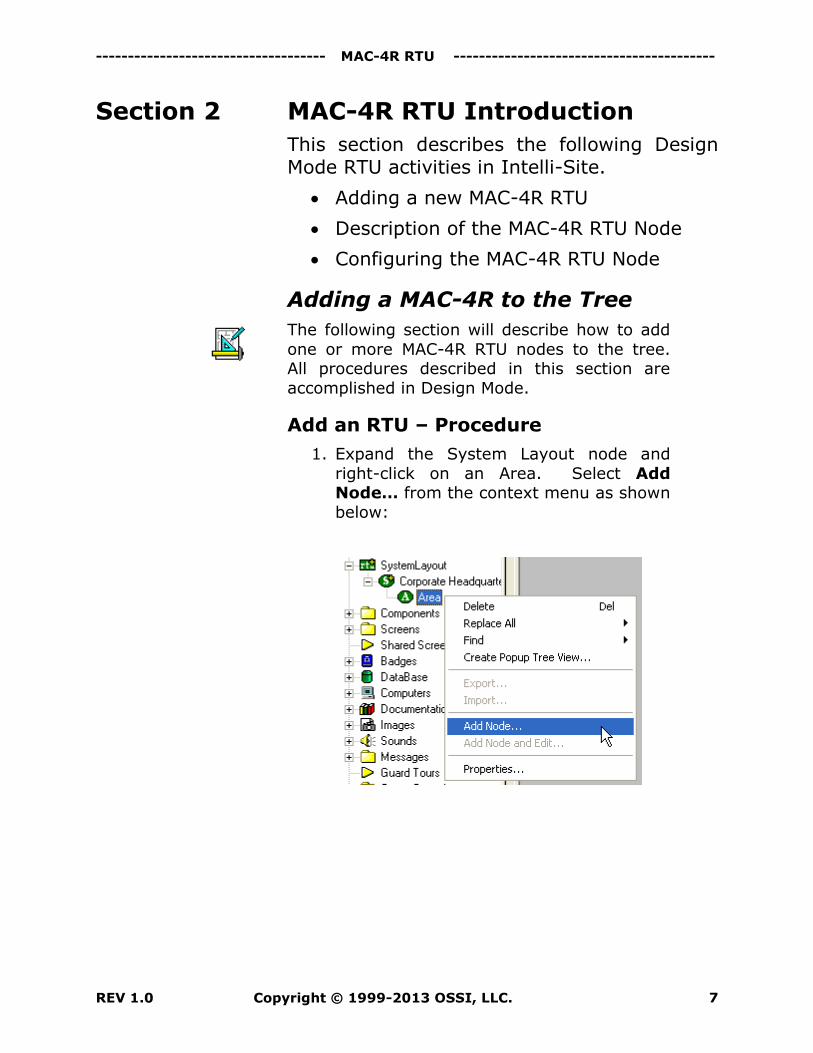
Add an RTU – Procedure
1. Expand the System Layout node and
right-click on an Area. Select Add Node… from the context menu as shown
below:
--------------------------------- MAC-4R RTU Guide -------------------------------------- -
Copyright © 1999-2013 OSSI, LLC. REV 1.0 8
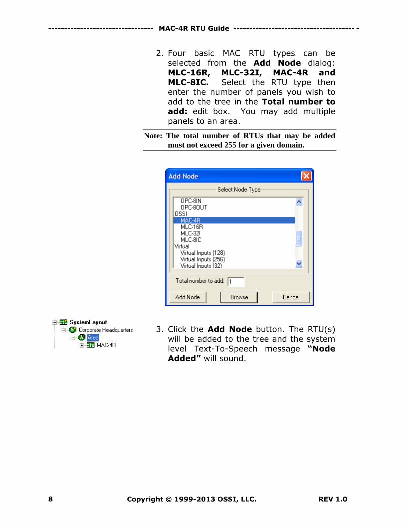
2. Four basic MAC RTU types can be
selected from the Add Node dialog: MLC-16R, MLC-32I, MAC-4R and
MLC-8IC. Select the RTU type then enter the number of panels you wish to
add to the tree in the Total number to add: edit box. You may add multiple
panels to an area.
Note: The total number of RTUs that may be added
must not exceed 255 for a given domain.
3. Click the Add Node button. The RTU(s)
will be added to the tree and the system
level Text-To-Speech message “Node Added” will sound.
------------------------------------ MAC-4R RTU -----------------------------------------
REV 1.0 Copyright © 1999-2013 OSSI, LLC. 9
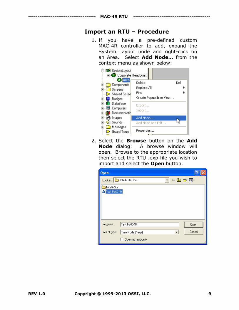
Import an RTU – Procedure
1. If you have a pre-defined custom MAC-4R controller to add, expand the
System Layout node and right-click on an Area. Select Add Node… from the
context menu as shown below:
2. Select the Browse button on the Add Node dialog: A browse window will
open. Browse to the appropriate location then select the RTU .exp file you wish to
import and select the Open button.
--------------------------------- MAC-4R RTU Guide -------------------------------------- -
Copyright © 1999-2013 OSSI, LLC. REV 1.0 10
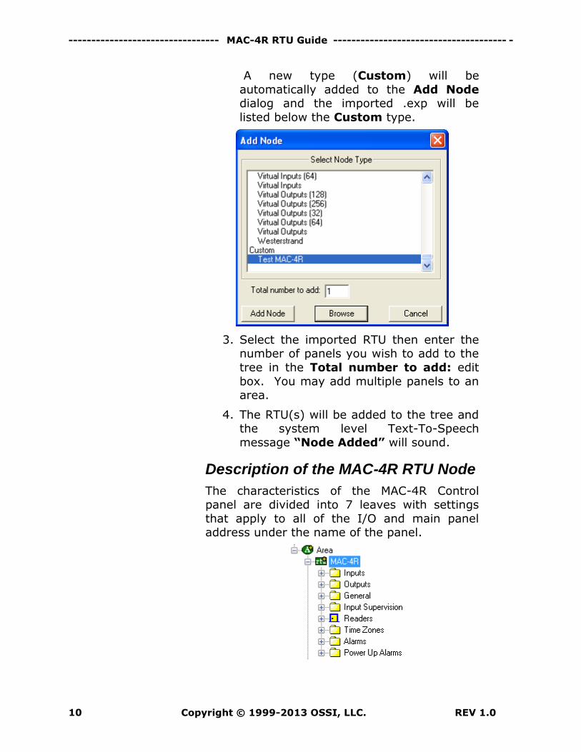
A new type (Custom) will be
automatically added to the Add Node dialog and the imported .exp will be
listed below the Custom type.
3. Select the imported RTU then enter the number of panels you wish to add to the
tree in the Total number to add: edit
box. You may add multiple panels to an area.
4. The RTU(s) will be added to the tree and the system level Text-To-Speech
message “Node Added” will sound.
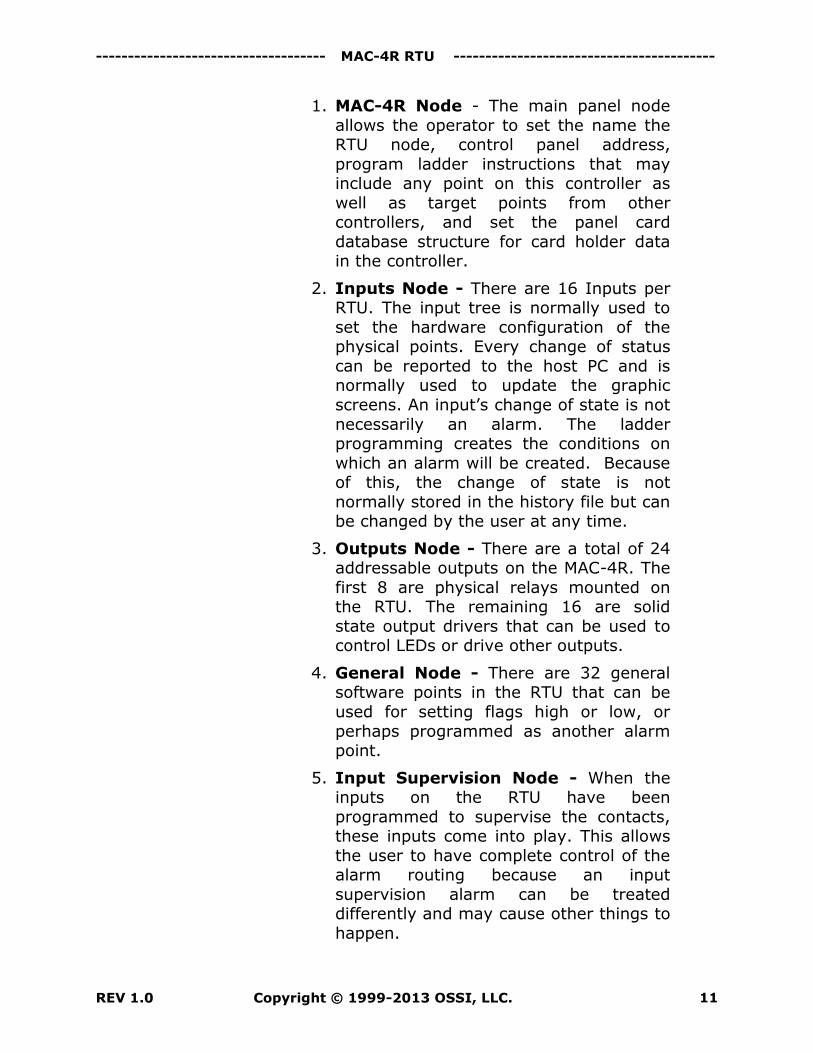
Description of the MAC-4R RTU Node
The characteristics of the MAC-4R Control panel are divided into 7 leaves with settings
that apply to all of the I/O and main panel address under the name of the panel.
------------------------------------ MAC-4R RTU -----------------------------------------
REV 1.0 Copyright © 1999-2013 OSSI, LLC. 11
1. MAC-4R Node - The main panel node
allows the operator to set the name the RTU node, control panel address,
program ladder instructions that may include any point on this controller as
well as target points from other controllers, and set the panel card
database structure for card holder data in the controller.
2. Inputs Node - There are 16 Inputs per RTU. The input tree is normally used to
set the hardware configuration of the physical points. Every change of status
can be reported to the host PC and is normally used to update the graphic
screens. An input’s change of state is not
necessarily an alarm. The ladder programming creates the conditions on
which an alarm will be created. Because of this, the change of state is not
normally stored in the history file but can be changed by the user at any time.
3. Outputs Node - There are a total of 24 addressable outputs on the MAC-4R. The
first 8 are physical relays mounted on the RTU. The remaining 16 are solid
state output drivers that can be used to control LEDs or drive other outputs.
4. General Node - There are 32 general software points in the RTU that can be
used for setting flags high or low, or
perhaps programmed as another alarm point.
5. Input Supervision Node - When the inputs on the RTU have been
programmed to supervise the contacts, these inputs come into play. This allows
the user to have complete control of the alarm routing because an input
supervision alarm can be treated differently and may cause other things to
happen.
--------------------------------- MAC-4R RTU Guide -------------------------------------- -
Copyright © 1999-2013 OSSI, LLC. REV 1.0 12
6. Doors (Readers) Node - There are 4
readers per RTU, all of which are independently programmed. The reader
setting screen controls the basic operational mode of the reader and is
also used to set the bit structure.
7. Time Zones Node - There are a total of
64 time zones in the MAC-4R RTU. These nodes are not the actual time zones but
are I/O points used to indicate if a time zone is active. They are also used in
ladder programming.
The actual time zones are configured
under the Access Control node. These time zones are global and used by every
MAC RTU in your system. Once the time
zones are added or modified the RTU’s time zone nodes are updated to match.
8. Alarms Node - There are 32 Alarm points in the RTU. Points 1-13 are
predefined and reflect different types of hardware-related alarms. The first 13 are
used by the firmware and should not be used for any thing else. Points 14-32 are
user definable and should be renamed to reflect the true nature of the alarm. The
Alarm points are not physical points on the RTU. The ladder programming of the
RTU ties the inputs together with the alarm points to create alarms when all
the conditions creating the alarm have
been met.
Configuring the MAC-4R RTU Node
The MAC-4R RTU node must be configured to
link to the physical MAC-4R panel. Once it is linked, the RTU node can be used to modify
and control the physical panel. The RTU is
configured via the Properties… dialog. To open the Properties… dialog, right-click on
the RTU node and select “Properties…” from the context Menu.
------------------------------------ MAC-4R RTU -----------------------------------------
REV 1.0 Copyright © 1999-2013 OSSI, LLC. 13
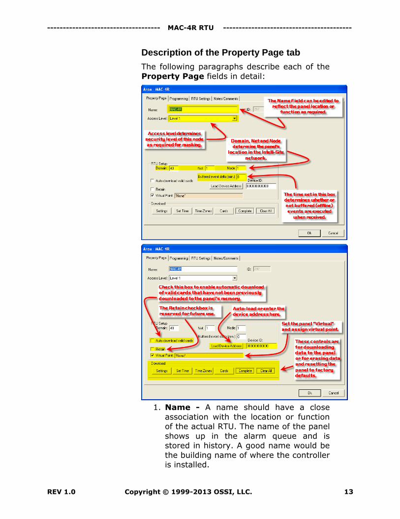
Description of the Property Page tab
The following paragraphs describe each of the
Property Page fields in detail:
1. Name - A name should have a close
association with the location or function of the actual RTU. The name of the panel
shows up in the alarm queue and is stored in history. A good name would be
the building name of where the controller is installed.
--------------------------------- MAC-4R RTU Guide -------------------------------------- -
Copyright © 1999-2013 OSSI, LLC. REV 1.0 14
2. ID - System generated
3. Domain, Net, Node: - All RTU addresses must be unique within the
system. Intelli-Site will automatically assign the next available number when
adding panels (RTUs). There are three fields for entering the node address.
These fields must be matched to the appropriate Driver settings in the
Intelli-Site Driver Service program. See Example network topology diagram
below.
a. Domain: A number between 1 and
65,530. This field determines which communications driver is
used.
b. Net: Lon-Works Network subnet – A number between 1 and 254
c. Node: Lon-Works Network node - A number between 1 and 127
4. Buffered event delta (min): - When unbuffering old data from a controller it
would be inaccurate to change the screen icons or provide a host interlock
on old events. Any event older than the Buffered event delta value will only be
stored to the history file. Enter a number (in minutes) that will determine if an
event is outside of the buffered delta range for host actions.
5. Auto download valid cards: - Cards
are automatically added to the RTU when added to the database. If the RTU was
off-line at the time there is a change that a card would not make it to the
controller. When a card is presented to a reader on this panel the host will
evaluate the event and check to see if the card should be valid for this
controller. If the card is valid the host will download the card record to the
panel immediately.
------------------------------------ MAC-4R RTU -----------------------------------------
REV 1.0 Copyright © 1999-2013 OSSI, LLC. 15
6. Virtual Point: - Check this box to place
the panel in Service or “virtualize” the panel. When an RTU has been
virtualized all Server-to-Driver (in the Driver Service) communications stop and
will not be reinitiated until the RTU has been un-virtualized. Drag-and-drop a
virtual I/O point into the drop field. This I/O point will be set high whenever the
panel is virtualized.
7. Download – The fields in this group
allow the user to download data to the panel. The user may download
Settings, Set Time, Time Zones, Cards, or Complete (Time Zones,
Cards and Settings). The Settings
download includes all the I/O point configuration data including time zones
and ladder logic. Whenever you change the hardware configuration of Inputs,
Outputs, or Readers you must come back to this screen and download Settings to
send those changes to the controller. Cards on the other hand are
automatically downloaded when ever you make a change. A Settings and Cards
download would be the same as sending a Complete download.
a. The user may also Set Time (date and time), or reset all panel
memory settings to the factory
defaults (Clear All).
b. Cards: Whenever you add a new
controller to the database it will need an initial Cards download to
get started. This download removes all the cards from the
controller before it starts a fresh download. This would remove any
cards not currently in the Intelli-Site database so only
authorized cards are loaded.
--------------------------------- MAC-4R RTU Guide -------------------------------------- -
Copyright © 1999-2013 OSSI, LLC. REV 1.0 16
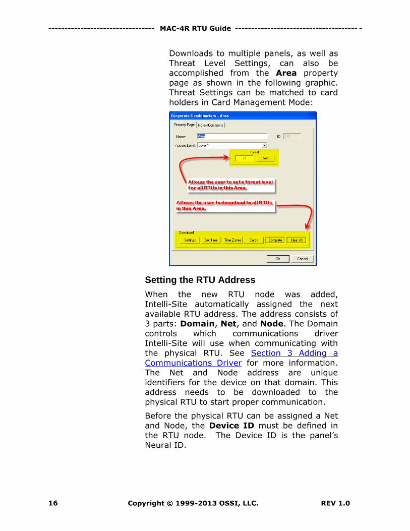
Downloads to multiple panels, as well as
Threat Level Settings, can also be accomplished from the Area property
page as shown in the following graphic. Threat Settings can be matched to card
holders in Card Management Mode:
Setting the RTU Address
When the new RTU node was added, Intelli-Site automatically assigned the next
available RTU address. The address consists of 3 parts: Domain, Net, and Node. The Domain
controls which communications driver Intelli-Site will use when communicating with
the physical RTU. See Section 3 Adding a
Communications Driver for more information. The Net and Node address are unique
identifiers for the device on that domain. This address needs to be downloaded to the
physical RTU to start proper communication.
Before the physical RTU can be assigned a Net
and Node, the Device ID must be defined in the RTU node. The Device ID is the panel’s
Neural ID.
------------------------------------ MAC-4R RTU -----------------------------------------
REV 1.0 Copyright © 1999-2013 OSSI, LLC. 17
Importing the Device ID
To acquire the Neural ID and associate the new
RTU node to the physical RTU:
1. Set up the driver in the Driver Service as
described in Section 3 Adding a Communications Driver. You will need a
driver for each Domain. Make sure the physical RTU and driver are
communicating before proceeding.
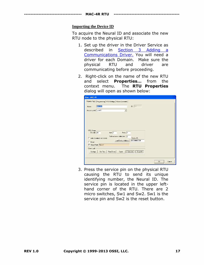
2. Right-click on the name of the new RTU
and select Properties… from the context menu. The RTU Properties
dialog will open as shown below:
3. Press the service pin on the physical RTU causing the RTU to send its unique
identifying number, the Neural ID. The service pin is located in the upper left-
hand corner of the RTU. There are 2 micro switches, Sw1 and Sw2. Sw1 is the
service pin and Sw2 is the reset button.
--------------------------------- MAC-4R RTU Guide -------------------------------------- -
Copyright © 1999-2013 OSSI, LLC. REV 1.0 18
After pressing the service pin on the
MAC-4R control panel, if all of the communication lines are working
properly, you will receive a message “New Neural ID has been received. Do
you wish to set the address?” Select Yes. This action will take the Neural ID
and place it in the Device ID field on the screen. Click the Apply button or the
Save button to save the new address.
Entering the Device ID
Another method is to manually enter the
number from the supplied MAC-4R Test Sheet. The installer can enter the Neural ID of each
node into the twelve-digit Device ID field on the node's Property Page tab. Click the
Apply or Save button to save the information.
Load the Device Address and Download Settings
Once the Device ID is set, we need to send the Net and Node address to the RTU.
Click the Load Device Address button. This function sets the address of the control panel
to the Domain.Net.Node address specified on this screen. From now on this panel will receive
all commands sent to this Domain.Net.Node address.
Before any inputs start transmitting to the host computer you must download Settings to the
controller.
------------------------------------ MAC-4R RTU -----------------------------------------
REV 1.0 Copyright © 1999-2013 OSSI, LLC. 19
Section 3 RTU Basic Set-up and Communications
This section describes the following Design Mode RTU activities in Intelli-Site.
Setting up a MAC-4R Communications Driver
Programming the RTU’s Point Settings
This section is used to establish initial
communications with the controller and program initial functionality.
Adding a Communications Driver (MAC-4R)
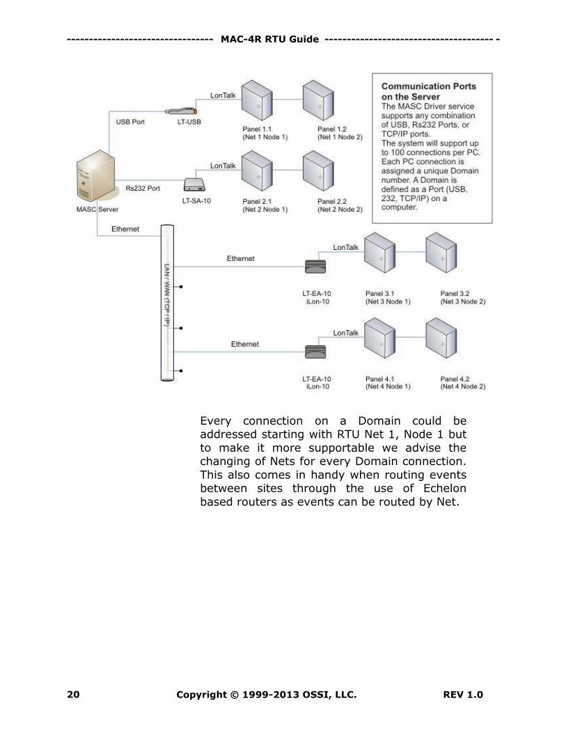
There are 3 different types of communication to a MAC-4R series controller: Ethernet, USB,
or RS232. The Ethernet and USB adapters use low level Windows drivers called OpenLDV
while the RS-232 port does not require the loading of OpenLDV. The drivers are multi-
threaded so every loop of controllers is independent from the other. Each use of an
Ethernet, USB, or RS-232 port requires a unique Domain address. A Domain can be
defined as a port on a Computer within the system. A remote IP address through OpenLDV
also requires a unique Domain address as each IP address it technically a different port.
The illustration below will require 4 unique
domain addresses.
--------------------------------- MAC-4R RTU Guide -------------------------------------- -
Copyright © 1999-2013 OSSI, LLC. REV 1.0 20
Every connection on a Domain could be addressed starting with RTU Net 1, Node 1 but
to make it more supportable we advise the changing of Nets for every Domain connection.
This also comes in handy when routing events between sites through the use of Echelon
based routers as events can be routed by Net.
------------------------------------ MAC-4R RTU -----------------------------------------
REV 1.0 Copyright © 1999-2013 OSSI, LLC. 21
Since Intelli-Site supports over 50 different
drivers, we have default domains for each manufacturer. The MAC-4R drivers normally
start at domain 40 and move up from there. So for this example, we are going to use
domains 41, 42, 43, and 44. Domain 41 will be assigned to the controllers on Net 1. Domain
42 will be assigned to the controllers on Net 2, etc… When we add a controller, it has a default
Domain address of 40; therefore, it is not assigned to any Domain network until we
change it.
Install the OpenLDV Driver
Install the Windows OpenLDV driver for the
USB adapter or the Ethernet adapter.
Adding a USB Adapter
Exit Intelli-Site and load the Windows OpenLDV
Drivers. You’ll find these drivers on the
Intelli-Site System DVD in a directory called OpenLDV. They can also be found on the
ossi-usa.com website.
After you load the drivers, plug in the USB
adapter. Since this is the first USB adapter loaded on the system it should be recognized
as LON1. The second adapter will be LON2 etc... To verify this you can go to the Windows
Control Panel -> Lonworks Interfaces and view the USB tab.
--------------------------------- MAC-4R RTU Guide -------------------------------------- -
Copyright © 1999-2013 OSSI, LLC. REV 1.0 22
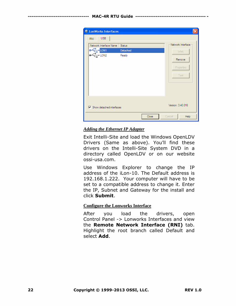
Adding the Ethernet IP Adapter
Exit Intelli-Site and load the Windows OpenLDV Drivers (Same as above). You’ll find these
drivers on the Intelli-Site System DVD in a directory called OpenLDV or on our website
ossi-usa.com.
Use Windows Explorer to change the IP
address of the iLon-10. The Default address is 192.168.1.222. Your computer will have to be
set to a compatible address to change it. Enter
the IP, Subnet and Gateway for the install and click Submit.
Configure the Lonworks Interface
After you load the drivers, open Control Panel -> Lonworks Interfaces and view
the Remote Network Interface (RNI) tab. Highlight the root branch called Default and
select Add.
------------------------------------ MAC-4R RTU -----------------------------------------
REV 1.0 Copyright © 1999-2013 OSSI, LLC. 23
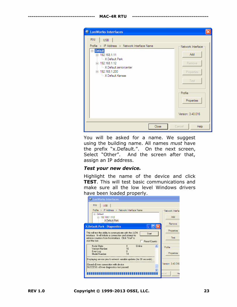
You will be asked for a name. We suggest using the building name. All names must have
the prefix “x.Default.”. On the next screen, Select “Other”. And the screen after that,
assign an IP address.
Test your new device.
Highlight the name of the device and click
TEST. This will test basic communications and make sure all the low level Windows drivers
have been loaded properly.
--------------------------------- MAC-4R RTU Guide -------------------------------------- -
Copyright © 1999-2013 OSSI, LLC. REV 1.0 24
Add a MAC-4R Driver in the Driver Service
Note: For each Domain, there must be at least one RTU
node in the tree in the Workstation with that
Domain. For this example, there should be 8
MAC-4R RTU nodes. These 8 nodes have 4
Domains numbered 41, 42, 43, and 44. See
Section 2 Adding a MAC-4R to the Tree.
Open the Intelli-Site Driver Service by
right-clicking on the double green box in the system tray and select Open. The Driver
Service window will appear.
Click the Add button to add a driver.
Select MAC-4R Driver from the list of available. Then click the OK button.
Select OpenLDV. If OpenLDV is not in the
list, you will have to reboot your computer so the OpenLDV drivers are
registered before Intelli-Site starts.
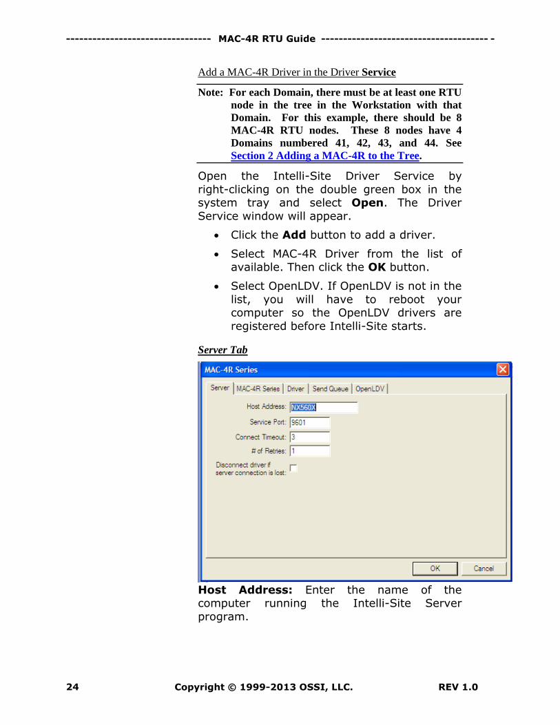
Server Tab
Host Address: Enter the name of the computer running the Intelli-Site Server
program.
------------------------------------ MAC-4R RTU -----------------------------------------
REV 1.0 Copyright © 1999-2013 OSSI, LLC. 25
Service Port: Base port address plus the last
number in the project subdirectory name. If the base address for communications is 9600
and the project name is Project_001, the Service port should be 9601. This service port
is the same for all instances of the driver so even though we need 4 Domains every driver
will be assigned the same service port of 9601.
Don’t change any thing else on this tab.
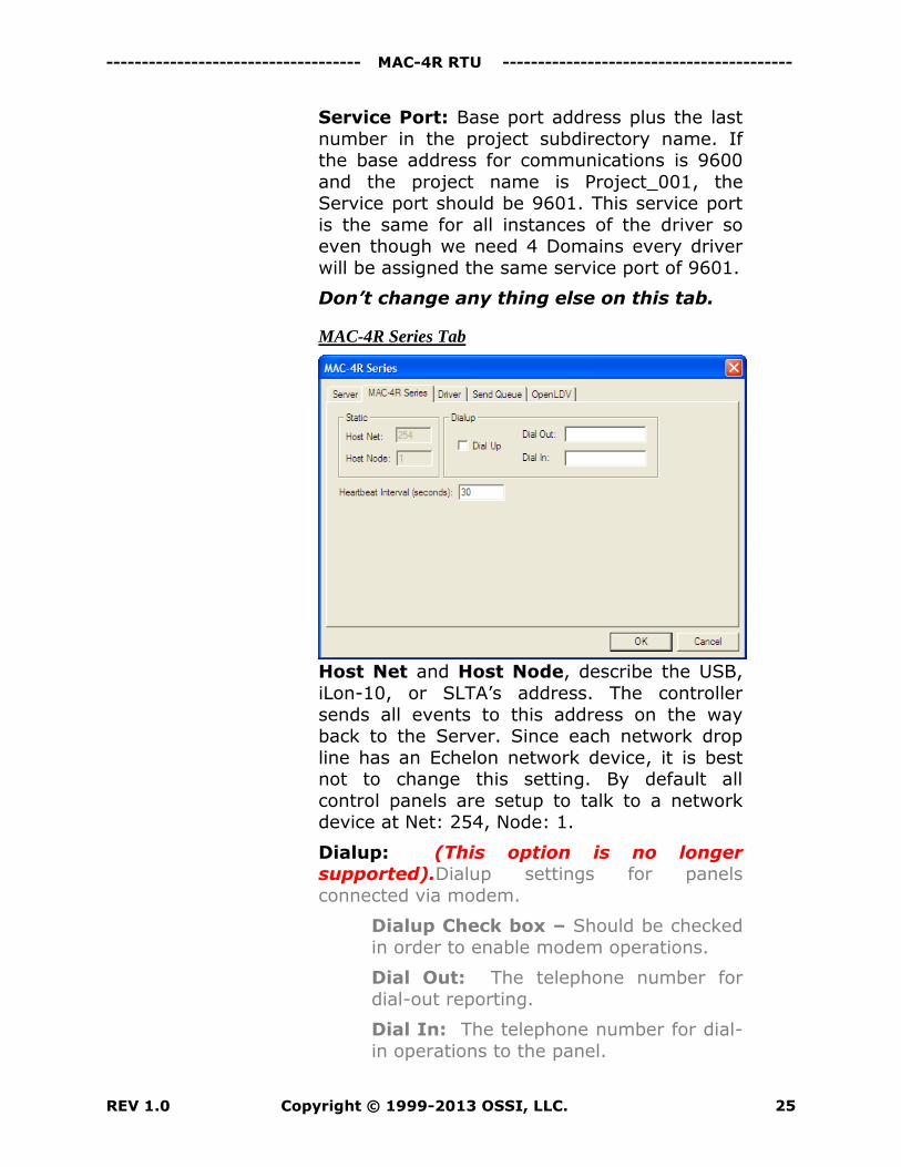
MAC-4R Series Tab
Host Net and Host Node, describe the USB,
iLon-10, or SLTA’s address. The controller
sends all events to this address on the way back to the Server. Since each network drop
line has an Echelon network device, it is best not to change this setting. By default all
control panels are setup to talk to a network device at Net: 254, Node: 1.
Dialup: (This option is no longer supported).Dialup settings for panels
connected via modem.
Dialup Check box – Should be checked
in order to enable modem operations.
Dial Out: The telephone number for
dial-out reporting.
Dial In: The telephone number for dial-
in operations to the panel.
--------------------------------- MAC-4R RTU Guide -------------------------------------- -
Copyright © 1999-2013 OSSI, LLC. REV 1.0 26
Heartbeat Interval (seconds) – This
determines the frequency of poll commands to a given loop of controllers. Since the RTU’s do
not need a poll to transmit, the only reason for the poll is to supervise the communications
line. The total interval time between heartbeats from the first panel to the last
panel on that com line. For best throughput, take the total number of controllers on the com
line and multiply it by 20 or 30. For example if you have 20 controllers, 20 x 20 = 400. The
system will poll all 20 controllers within 400 seconds. This provides 20 seconds in between
polls for activity and commands.
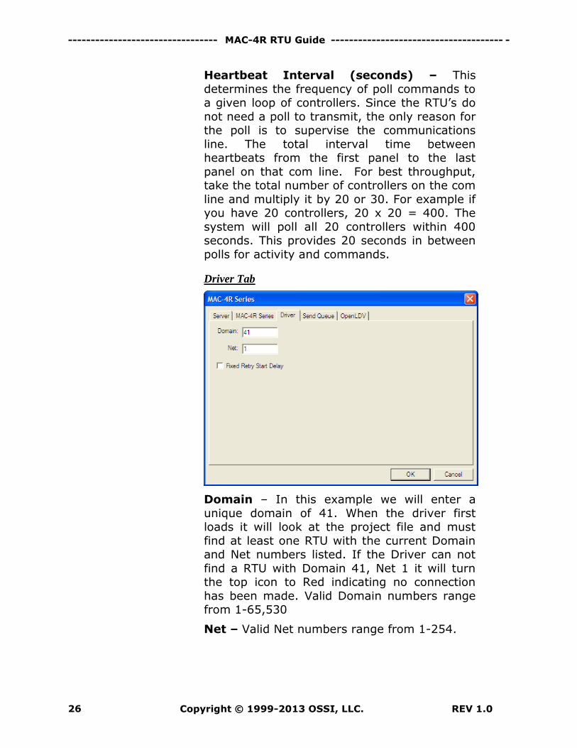
Driver Tab
Domain – In this example we will enter a
unique domain of 41. When the driver first loads it will look at the project file and must
find at least one RTU with the current Domain and Net numbers listed. If the Driver can not
find a RTU with Domain 41, Net 1 it will turn the top icon to Red indicating no connection
has been made. Valid Domain numbers range from 1-65,530
Net – Valid Net numbers range from 1-254.
------------------------------------ MAC-4R RTU -----------------------------------------
REV 1.0 Copyright © 1999-2013 OSSI, LLC. 27
Send Queue Tab
The values here control the number of RTU
commands sent before a Panel Off-Line event is created.
Since the Echelon Network Interface always knows if a RTU is communicating, many time
the Network Interface will inform the Driver Service that this RTU is not there by sending a
“x15 o NAK” back to the Driver Service. When the Driver Service receives a NAK it will not
retry the command. If on the other hand no response is received from the Echelon Network
Interface, the retries will go out as programmed here.
We do not recommend changing any values here.
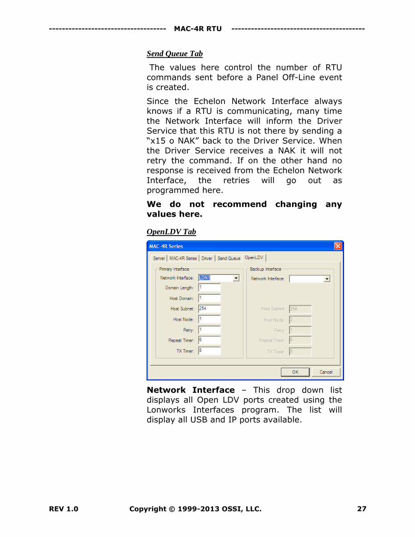
OpenLDV Tab
Network Interface – This drop down list displays all Open LDV ports created using the
Lonworks Interfaces program. The list will display all USB and IP ports available.
--------------------------------- MAC-4R RTU Guide -------------------------------------- -
Copyright © 1999-2013 OSSI, LLC. REV 1.0 28
Backup Interface – Echelon offers the
feature of redundant Network interfaces. If the primary interface fails the backup interface will
take it’s place. This is the same list of devices displayed under Network Interface. You can
not have the same device operating under both rolls. If you do not have (2) network interfaces
on a single loop just leave this one blank.
No other changes are needed beyond this
point.
Domain Length – This is the length in bytes
of the Hardware Domain number of the MAC-4R equipment.
Host Domain - This is the Hardware domain of the MAC-4R equipment. By default all
equipment is shipped to operate on Domain 1.
Host Subnet, Host Node – This will be the Echelon address of the USB or IP device
installed on this port. By default all control panels are programmed to communicate
through a network interface at Subnet 254, Node 1. If you change this parameter you will
also have to change the settings of each MAC-4R on the network.
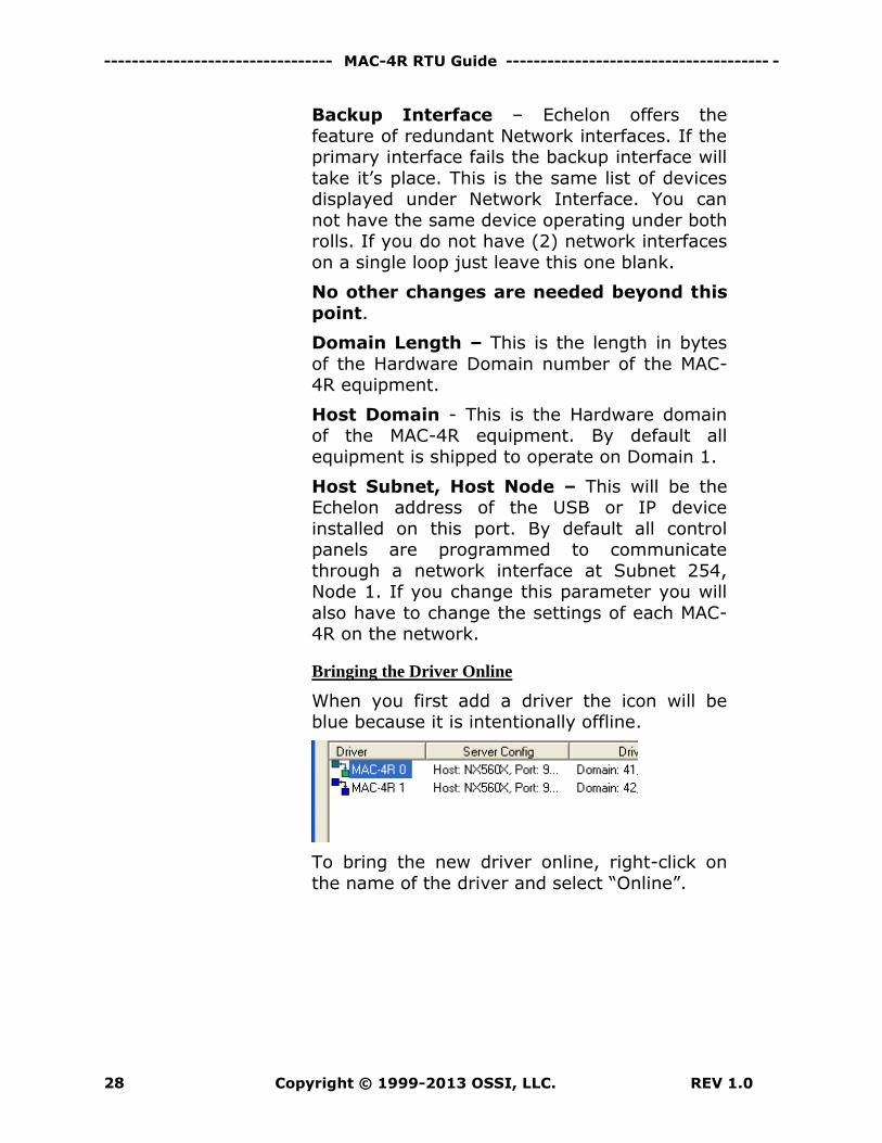
Bringing the Driver Online
When you first add a driver the icon will be blue because it is intentionally offline.
To bring the new driver online, right-click on
the name of the driver and select “Online”.
------------------------------------ MAC-4R RTU -----------------------------------------
REV 1.0 Copyright © 1999-2013 OSSI, LLC. 29
If the controller is working properly the icon
should turn green (top) and green (bottom). The top box indicates the driver is talking to
the Intelli-Site Server. The bottom box indicates communications with the Lon-Talk
Network interface. Green means everything is working properly. Blue means it is
intentionally offline. Red means the communication link is broken. Yellow means
the link is partially up.
Once the driver is online make sure to
configure the RTU according to Section 2 Configuring the MAC4R RTU Node
You now have an operational MAC-4R RTU!
Clear any Events from the Alarm Queue from
Unknown Panel. If you are still getting
unknown Panel Events the MAC-4R never received its correct panel address.
Valid Communications is always reported through the Panel Online/Offline status.
If for any reason the host computer is unable to talk to a MAC-4R controller, you
will receive a MAC-4R Panel Status Offline Alarm.
Troubleshooting Communication Issues
If for some reason the MAC-4R is not communicating, Intelli-Site offers a data scope
of the Communications Line.
Open the Driver Service.
Right-click on the name of the driver and select “Messages”.
Right-click on the banner and select
“Always on Top”.
Make sure Message Types of “MAC-4R”
is checked.
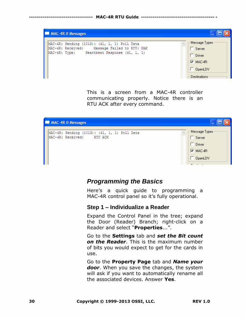
The messages displayed in the following figure
are from a com loop where the controller is not connected properly to the USB adapter.
--------------------------------- MAC-4R RTU Guide -------------------------------------- -
Copyright © 1999-2013 OSSI, LLC. REV 1.0 30
This is a screen from a MAC-4R controller
communicating properly. Notice there is an RTU ACK after every command.
Programming the Basics
Here’s a quick guide to programming a
MAC-4R control panel so it’s fully operational.
Step 1 – Individualize a Reader
Expand the Control Panel in the tree; expand the Door (Reader) Branch; right-click on a
Reader and select “Properties...”.
Go to the Settings tab and set the Bit count
on the Reader. This is the maximum number of bits you would expect to get for the cards in
use.
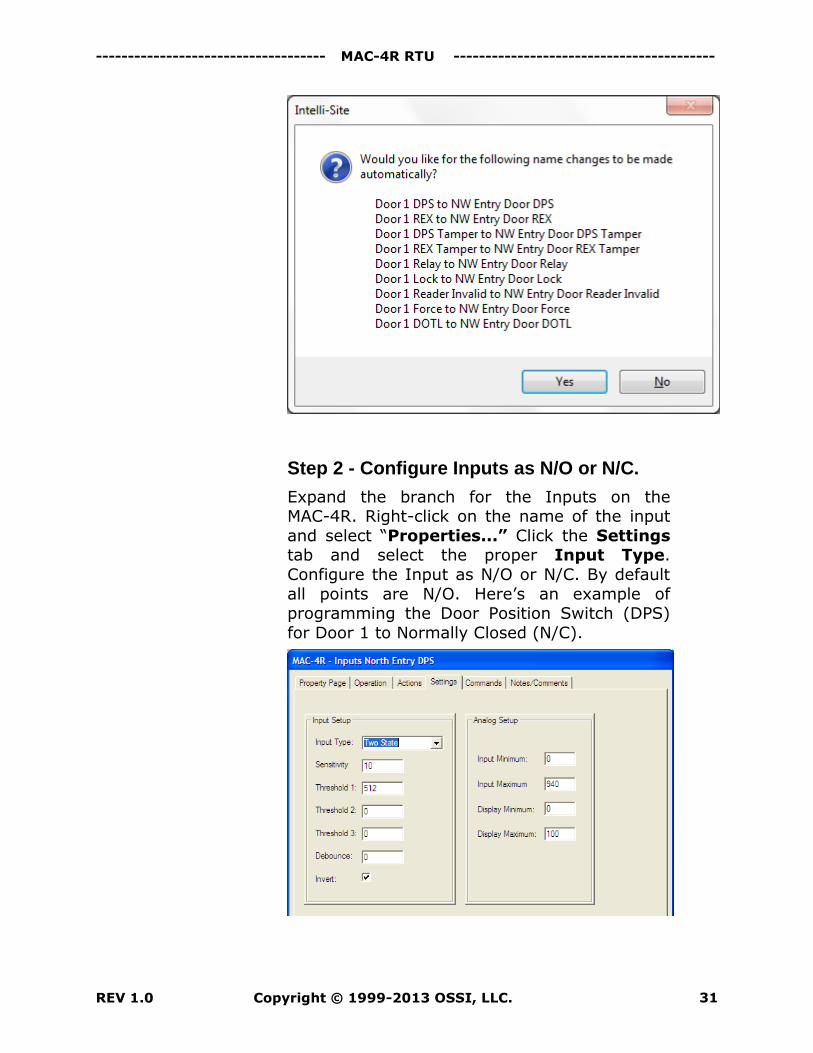
Go to the Property Page tab and Name your
door. When you save the changes, the system will ask if you want to automatically rename all
the associated devices. Answer Yes.
------------------------------------ MAC-4R RTU -----------------------------------------
REV 1.0 Copyright © 1999-2013 OSSI, LLC. 31
Step 2 - Configure Inputs as N/O or N/C.
Expand the branch for the Inputs on the MAC-4R. Right-click on the name of the input
and select “Properties...” Click the Settings tab and select the proper Input Type.
Configure the Input as N/O or N/C. By default
all points are N/O. Here’s an example of programming the Door Position Switch (DPS)
for Door 1 to Normally Closed (N/C).
--------------------------------- MAC-4R RTU Guide -------------------------------------- -
Copyright © 1999-2013 OSSI, LLC. REV 1.0 32
Go to all remaining inputs that are N/C and
add the check mark in the Invert Field.
For details instructions on changing the
point type refer to the Input Section below.
Step 3 - Configure Door Operation
By default the MAC-4R has all 4 doors setup for Reader In, Rex Out by pulsing the Relay. If
this matches your install you don’t need to do anything in this step and can proceed to the
next step.
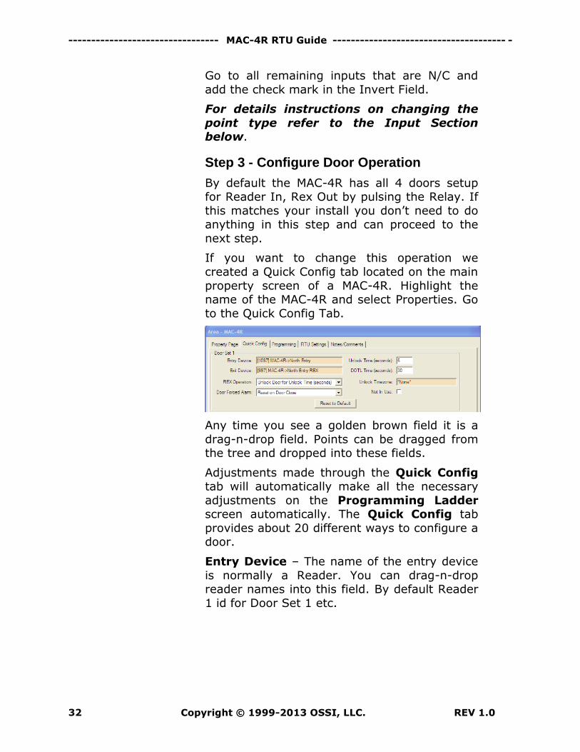
If you want to change this operation we
created a Quick Config tab located on the main
property screen of a MAC-4R. Highlight the name of the MAC-4R and select Properties. Go
to the Quick Config Tab.
Any time you see a golden brown field it is a
drag-n-drop field. Points can be dragged from the tree and dropped into these fields.
Adjustments made through the Quick Config tab will automatically make all the necessary
adjustments on the Programming Ladder screen automatically. The Quick Config tab
provides about 20 different ways to configure a door.
Entry Device – The name of the entry device
is normally a Reader. You can drag-n-drop reader names into this field. By default Reader
1 id for Door Set 1 etc.
------------------------------------ MAC-4R RTU -----------------------------------------
REV 1.0 Copyright © 1999-2013 OSSI, LLC. 33
Exit Device – This could be a Reader or a
REX. If you have Reader 1 and an IN Reader, and Reader 2 as an OUT reader, go to Door Set
2 and check the “Not in Use”. This will eliminate all the attachments from Reader 2 to
its Door Set.
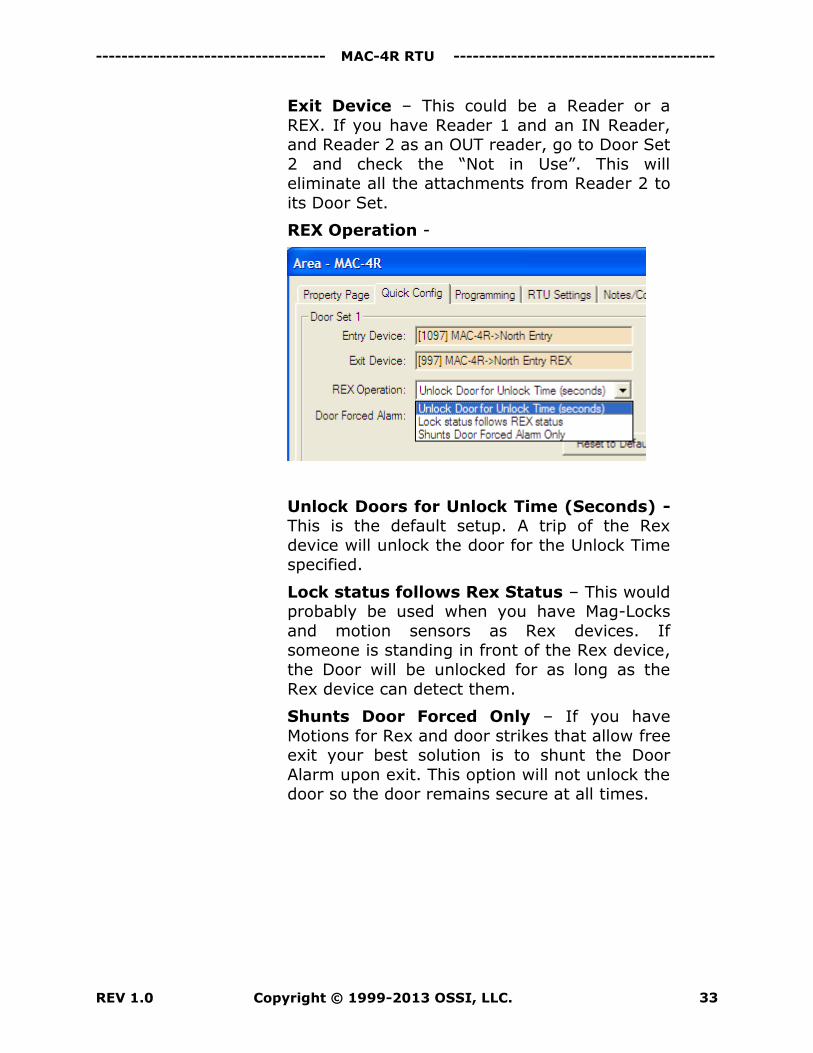
REX Operation -
Unlock Doors for Unlock Time (Seconds) - This is the default setup. A trip of the Rex
device will unlock the door for the Unlock Time specified.
Lock status follows Rex Status – This would probably be used when you have Mag-Locks
and motion sensors as Rex devices. If someone is standing in front of the Rex device,
the Door will be unlocked for as long as the
Rex device can detect them.
Shunts Door Forced Only – If you have
Motions for Rex and door strikes that allow free exit your best solution is to shunt the Door
Alarm upon exit. This option will not unlock the door so the door remains secure at all times.
--------------------------------- MAC-4R RTU Guide -------------------------------------- -
Copyright © 1999-2013 OSSI, LLC. REV 1.0 34
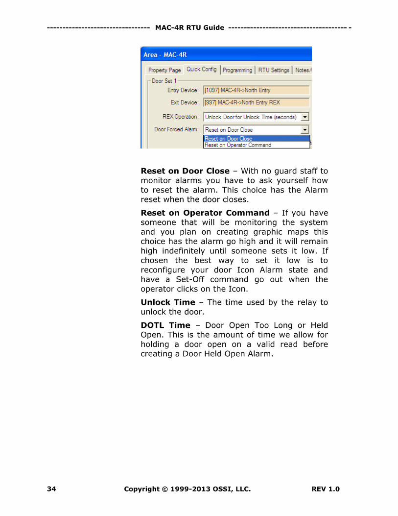
Reset on Door Close – With no guard staff to monitor alarms you have to ask yourself how
to reset the alarm. This choice has the Alarm reset when the door closes.
Reset on Operator Command – If you have someone that will be monitoring the system
and you plan on creating graphic maps this choice has the alarm go high and it will remain
high indefinitely until someone sets it low. If chosen the best way to set it low is to
reconfigure your door Icon Alarm state and have a Set-Off command go out when the
operator clicks on the Icon.
Unlock Time – The time used by the relay to
unlock the door.
DOTL Time – Door Open Too Long or Held Open. This is the amount of time we allow for
holding a door open on a valid read before creating a Door Held Open Alarm.
------------------------------------ MAC-4R RTU -----------------------------------------
REV 1.0 Copyright © 1999-2013 OSSI, LLC. 35
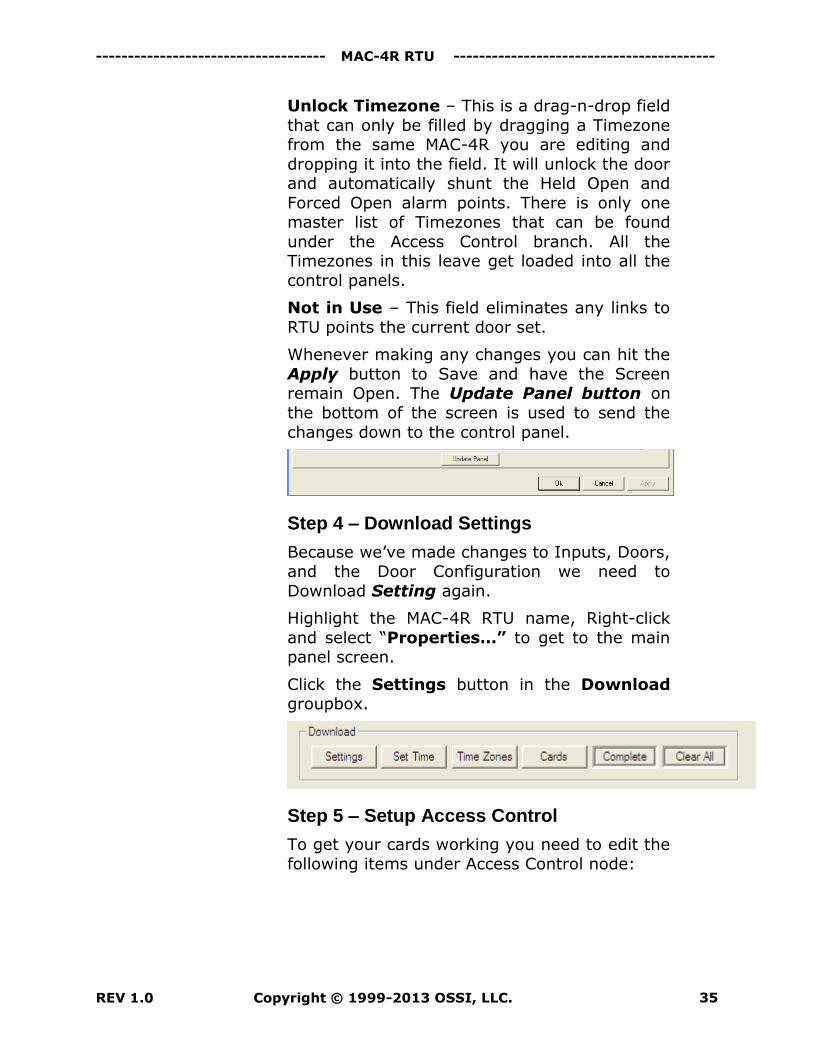
Unlock Timezone – This is a drag-n-drop field
that can only be filled by dragging a Timezone from the same MAC-4R you are editing and
dropping it into the field. It will unlock the door and automatically shunt the Held Open and
Forced Open alarm points. There is only one master list of Timezones that can be found
under the Access Control branch. All the Timezones in this leave get loaded into all the
control panels.
Not in Use – This field eliminates any links to
RTU points the current door set.
Whenever making any changes you can hit the
Apply button to Save and have the Screen remain Open. The Update Panel button on
the bottom of the screen is used to send the
changes down to the control panel.
Step 4 – Download Settings
Because we’ve made changes to Inputs, Doors, and the Door Configuration we need to
Download Setting again.
Highlight the MAC-4R RTU name, Right-click
and select “Properties…” to get to the main panel screen.
Click the Settings button in the Download groupbox.
Step 5 – Setup Access Control
To get your cards working you need to edit the
following items under Access Control node:
--------------------------------- MAC-4R RTU Guide -------------------------------------- -
Copyright © 1999-2013 OSSI, LLC. REV 1.0 36
Time zones, (Timezones must be
manually download after any change. Go to the Site or Area Screen to download
all the panels at one time.)
Access Groups, or Door Groups, A group
of doors assigned to an Access Set.
Access Set. A group of Door Groups that
can be assigned to a cardholder.
Add your cards and assign them an
Access Level which is any combination of multiple Access Sets.
Congratulations! Your basic programming is done!
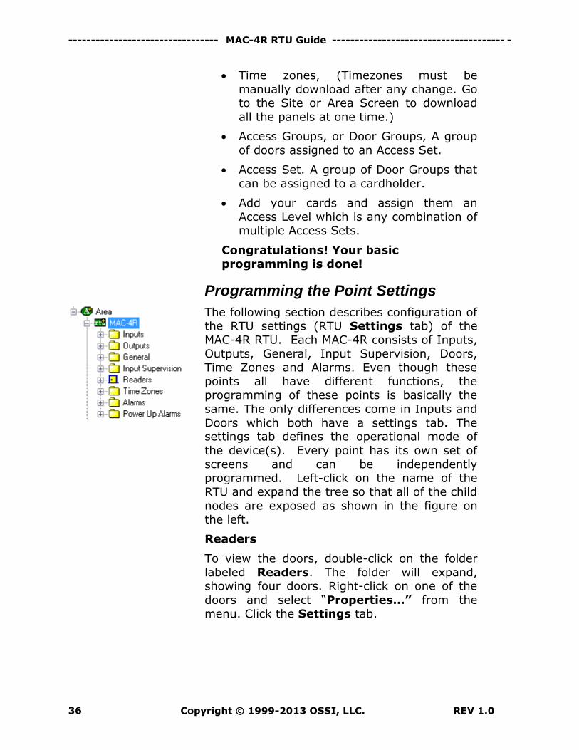
Programming the Point Settings
The following section describes configuration of
the RTU settings (RTU Settings tab) of the MAC-4R RTU. Each MAC-4R consists of Inputs,
Outputs, General, Input Supervision, Doors, Time Zones and Alarms. Even though these
points all have different functions, the programming of these points is basically the
same. The only differences come in Inputs and
Doors which both have a settings tab. The settings tab defines the operational mode of
the device(s). Every point has its own set of screens and can be independently
programmed. Left-click on the name of the RTU and expand the tree so that all of the child
nodes are exposed as shown in the figure on the left.
Readers
To view the doors, double-click on the folder
labeled Readers. The folder will expand, showing four doors. Right-click on one of the
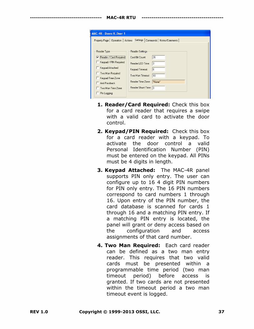
doors and select “Properties…” from the menu. Click the Settings tab.
------------------------------------ MAC-4R RTU -----------------------------------------
REV 1.0 Copyright © 1999-2013 OSSI, LLC. 37
1. Reader/Card Required: Check this box for a card reader that requires a swipe
with a valid card to activate the door control.
2. Keypad/PIN Required: Check this box for a card reader with a keypad. To
activate the door control a valid Personal Identification Number (PIN)
must be entered on the keypad. All PINs
must be 4 digits in length.
3. Keypad Attached: The MAC-4R panel
supports PIN only entry. The user can configure up to 16 4 digit PIN numbers
for PIN only entry. The 16 PIN numbers correspond to card numbers 1 through
16. Upon entry of the PIN number, the card database is scanned for cards 1
through 16 and a matching PIN entry. If a matching PIN entry is located, the
panel will grant or deny access based on the configuration and access
assignments of that card number.
4. Two Man Required: Each card reader
can be defined as a two man entry
reader. This requires that two valid cards must be presented within a
programmable time period (two man timeout period) before access is
granted. If two cards are not presented within the timeout period a two man
timeout event is logged.
--------------------------------- MAC-4R RTU Guide -------------------------------------- -
Copyright © 1999-2013 OSSI, LLC. REV 1.0 38
5. Keypad Timezone: When selected, this
will require keypad to look at time zone to see if keypad is in use.
6. Anti Passback: This puts the door in anti-passback mode of operation.
7. Two Man Timezone: This will require two man rule for the time specified in
the time zone field.
8. Pin Logging: Will allow the user to
specify any PIN.
9. Card bit count: The panel currently
supports standard 26, 32, 34, 35, 37, 40, and 48 bit card formats.
10. Reader LED time: Measured in seconds, allows the user to set how long
the LED changes state on valid reads.
11. Keypad timeout: Measured in seconds, determines how long the
control panel will wait for a PIN code before timing out.
12. Two Man Timeout: Measured in seconds, time lapse between the two
valid card swipes required to open the door if two man rule was specified.
13. Reader Timezone: The user can enable time zone override of keypad and
two man requirements for each reader. If override is configured and the
specified time zone is active or “On” then the function is not required for
access.
14. Reader Shunt Time: Measured in seconds, time card reader is disabled
after valid card swipe.
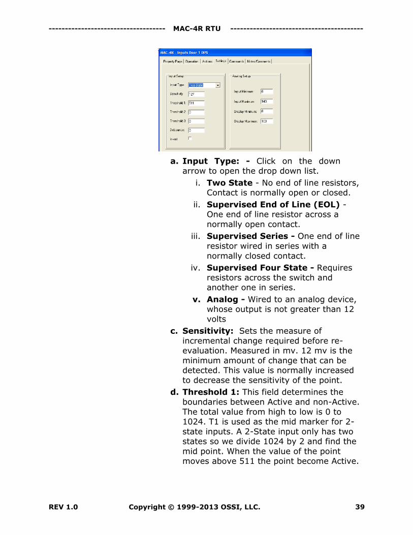
Inputs – To view the inputs, double-click on
the folder labeled Inputs. Right-click on one of the Inputs and select Properties from the
menu, then select the Settings Tab:
------------------------------------ MAC-4R RTU -----------------------------------------
REV 1.0 Copyright © 1999-2013 OSSI, LLC. 39
a. Input Type: - Click on the down arrow to open the drop down list.
i. Two State - No end of line resistors, Contact is normally open or closed.
ii. Supervised End of Line (EOL) - One end of line resistor across a
normally open contact.
iii. Supervised Series - One end of line
resistor wired in series with a
normally closed contact.
iv. Supervised Four State - Requires
resistors across the switch and another one in series.
v. Analog - Wired to an analog device, whose output is not greater than 12
volts
c. Sensitivity: Sets the measure of
incremental change required before re-evaluation. Measured in mv. 12 mv is the
minimum amount of change that can be detected. This value is normally increased
to decrease the sensitivity of the point.
d. Threshold 1: This field determines the
boundaries between Active and non-Active.
The total value from high to low is 0 to 1024. T1 is used as the mid marker for 2-
state inputs. A 2-State input only has two states so we divide 1024 by 2 and find the
mid point. When the value of the point moves above 511 the point become Active.
--------------------------------- MAC-4R RTU Guide -------------------------------------- -
Copyright © 1999-2013 OSSI, LLC. REV 1.0 40
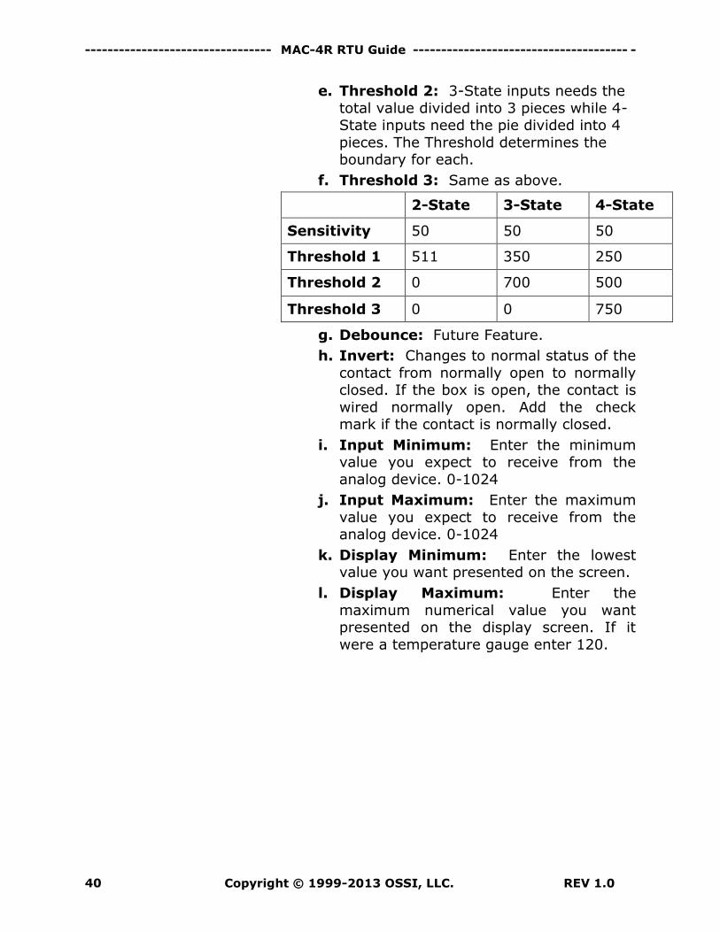
e. Threshold 2: 3-State inputs needs the
total value divided into 3 pieces while 4-State inputs need the pie divided into 4
pieces. The Threshold determines the boundary for each.
f. Threshold 3: Same as above.
2-State 3-State 4-State
Sensitivity 50 50 50
Threshold 1 511 350 250
Threshold 2 0 700 500
Threshold 3 0 0 750
g. Debounce: Future Feature.
h. Invert: Changes to normal status of the
contact from normally open to normally closed. If the box is open, the contact is
wired normally open. Add the check mark if the contact is normally closed.
i. Input Minimum: Enter the minimum value you expect to receive from the
analog device. 0-1024
j. Input Maximum: Enter the maximum
value you expect to receive from the analog device. 0-1024
k. Display Minimum: Enter the lowest value you want presented on the screen.
l. Display Maximum: Enter the
maximum numerical value you want presented on the display screen. If it
were a temperature gauge enter 120.
------------------------------------ MAC-4R RTU -----------------------------------------
REV 1.0 Copyright © 1999-2013 OSSI, LLC. 41
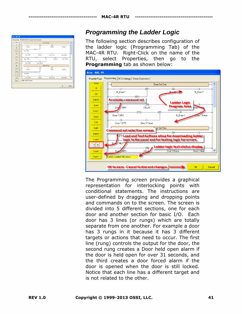
Programming the Ladder Logic
The following section describes configuration of
the ladder logic (Programming Tab) of the MAC-4R RTU. Right-Click on the name of the
RTU, select Properties, then go to the Programming tab as shown below:
The Programming screen provides a graphical representation for interlocking points with
conditional statements. The instructions are user-defined by dragging and dropping points
and commands on to the screen. The screen is divided into 5 different sections, one for each
door and another section for basic I/O. Each door has 3 lines (or rungs) which are totally
separate from one another. For example a door has 3 rungs in it because it has 3 different
targets or actions that need to occur. The first line (rung) controls the output for the door, the
second rung creates a Door held open alarm if the door is held open for over 31 seconds, and
the third creates a door forced alarm if the
door is opened when the door is still locked. Notice that each line has a different target and
is not related to the other.
--------------------------------- MAC-4R RTU Guide -------------------------------------- -
Copyright © 1999-2013 OSSI, LLC. REV 1.0 42
There are seven main categories of ladder
instructions located to the left of the graphic screen. The type of commands include: Input,
Constant, Branch, Analog, General1, General2, and Shunt. To display the ladder logic
programming commands in each set: use the
Command Set Selection buttons.
The rungs are read like an electrical drawing.
To provide electrical flow or to set a target(s)
high, closed connections are needed across the rung. When looking at the drawing, you cannot
look at the point as being opened or closed. A point is ether in its normal condition (set off)
or active (set on) condition.
The following symbols are used for points used
as sources for making decisions. The symbols can be dragged and dropped over the top of
another symbol to change it.
Has flow when the point is in its
normal condition.
No flow when the point is in its normal condition.
Every rung also has a value between 0 and 255. This allows for control and
monitoring of up to 8 points through one rung. If only one point is being
monitored the value will be 255 when
active and 0 when normal.
Basic Rules
The following rules apply to ladder logic
programming.
1. The first point coming off the left-hand side of
the screen is always considered a source or decision field. All source and Decision fields
should have a point name and use ether the
sign or sign.
2. Targets points are on the right side of the
rung and should have a command with curved
------------------------------------ MAC-4R RTU -----------------------------------------
REV 1.0 Copyright © 1999-2013 OSSI, LLC. 43
brackets. Available target commands come
from General 1 Set and Shunt Set.
3. The rung supports multiple target fields.
4. A target point is using a follow command it can only be used on one rung. It can not exist in
multiple rungs. If using a SetOn and SetOff command you can have the same target in two
different rungs.
5. All source or decision fields in the rung must
be from the controller you are programming.
6. Target points can be from the same controller
or different controllers.
Note: When comparing single points: use the Branch
command set.
Input Set
Input set commands are used to control 8 points per command. The set will monitor either the first
set of 8 or the second set of 8 points. A point must be provided to the set to determine which set is monitored. If the point provided is one of the first
8, it will monitor the first 8 points. If it’s one of the second, it will monitor the second set of points. A
value is created and compared with the rung.
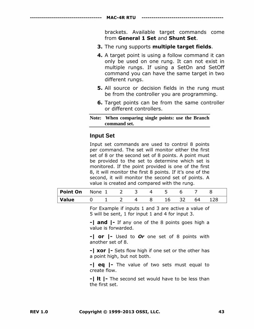
Point On None 1 2 3 4 5 6 7 8
Value 0 1 2 4 8 16 32 64 128
For Example if inputs 1 and 3 are active a value of 5 will be sent, 1 for input 1 and 4 for input 3.
-| and |- If any one of the 8 points goes high a
value is forwarded.
-| or |- Used to Or one set of 8 points with
another set of 8.
-| xor |- Sets flow high if one set or the other has
a point high, but not both.
-| eq |- The value of two sets must equal to
create flow.
-| lt |- The second set would have to be less than
the first set.
--------------------------------- MAC-4R RTU Guide -------------------------------------- -
Copyright © 1999-2013 OSSI, LLC. REV 1.0 44
-| gt |- The second set would have to be greater
than the first set.
-| add |- Adds value of the second set to the first
set.
-| sub |- Subtracts the value of the second set
from the first set.
Constant Set
Constant commands allow the user to specify a constant value in place of a second set of points.
The constant set should always follow the set it is compared with.
–[ and ]- Bit for bit comparison against the value
of the constant set. Bit value must be high in both
sets for bit to be set high in results.
–[ or ]- Bit for bit Or against the value of the
constant set. Will result in one, the other, or both.
–[ xor ]- Bit for bit XOr against the value of the
constant set which will result in one or the other,
but not both.
–[ eq ]- Bit for Bit compare with value of constant
set must be equal.
–[ lt ]- Compares the input value to the constant
set and if less than turns all bits high or low.
–[gt ]- Compares the input value to the constant
set and if greater than turns all bits high or low.
–[ add ]- Adds value of the constant set to
whatever the input value was.
–[ sub ]- Subtracts value of the constant set to
whatever the input value was.
Branch Set
The Branch set splits the rung into multiple paths
allowing logic between single points.
-< and >- Splits rung so both sources must be
high before target will be set high.
-< or >- Splits rung so if either rung goes high
the target will be set high.
-< xor >- Splits rung so if either one but not both
source rungs go high target will be set high.
------------------------------------ MAC-4R RTU -----------------------------------------
REV 1.0 Copyright © 1999-2013 OSSI, LLC. 45
-< eq >- Branch one needs to equal branch two.
-< lt >- Branch two needs to be less than branch
one.
-< gt >- Branch two needs to be greater than
branch one.
-< add >- Add branch two to branch one.
-< sub>- Subtract branch two from branch one.
Analog Set
Analog commands provide a value for one point between 0 and 255. The point being monitored must be setup for analog operation. The MAC-4R
provides 10 bit resolution, when monitored the two least significant bits are dropped.
-< and >- Used to AND two analog points
together.
-< or >- Used to OR two analog points together.
-< xor >- Used to XOR two analog points
together.
-< eq >- Brings the analog value as the second
value.
-< lt >- Compares the value set on LT to input
rung.
-< gt >- Compares the value set on GT to input
rung.
-< add >- Adds set value to rung.
-< sub>- Subtracts set value from rung.
General 1 Set
-/ inv /- Invert the bit pattern.
–( nonzero )- If any bit is on, turn all bits on.
–( os )- One Shot, will provide one opportunity to
set the target high. It will ignore the return to normal on the source field and provide the next
opportunity to set target high the next time source field goes high.
–( )- Target field: Target Point must be provided.
Target will follow state of source field unless otherwise specified with another command.
--------------------------------- MAC-4R RTU Guide -------------------------------------- -
Copyright © 1999-2013 OSSI, LLC. REV 1.0 46
–( o )- Send a Set-On command to Target Field.
Target point must be provided.
–( f )- Send a Set-Off command to Target Field.
Target point must be provided.
–( out )- Multiple Target Field, Controls 8
outputs. Targets follow state of Source fields.
–( out-o )- Multiple Target Field, Controls 8
outputs. Set-on command send to Output(s).
–( out-f )- Multiple Target Field, Controls 8
outputs. Set-off command send to Output(s)
General 2 Set
–( grp )- Card Group command is assigned to
Activation Group from the Card Holder Screen.
Group number must be specified. It requires Reader point and ActivationGroup. Right-click on
the GRP command after it’s in the ladder to set these values.
–( elev )- Not in use at this time.
–[ delay ]- Delays for the number of seconds
specified, if source still high create flow for target.
–[ pulse ]- Send Pulse command to target.
Number of seconds must be specified.
–[ count ]- Count number of times point goes
high before target gets set high. Count value must
be set (0-255).
–[ ct ]- If Card Type equals set value follow flow.
It requires Reader point and Card type selected. Right-click on the CT command after it’s in the
ladder to set these values.
–[ cn ]- If Card number equals set value follow
flow. It requires Reader point and Card number
selected. Right-click on the CN command after it’s in the ladder to set these values.
Shunt Set
–( s )- Shunt specified point, Shunt state follows
source field.
–( so )- Send Shunt-On command to specified
point.
------------------------------------ MAC-4R RTU -----------------------------------------
REV 1.0 Copyright © 1999-2013 OSSI, LLC. 47
–( sf )- Send Shunt-Off command to specified
point.
–( sout )- Shunt group of points. Shunt state
follows source fields.
–( sout-o )- Send Shunt-On command to
specified group of points.
–( sout-f )- Send Shunt-Off command to
specified group of points.
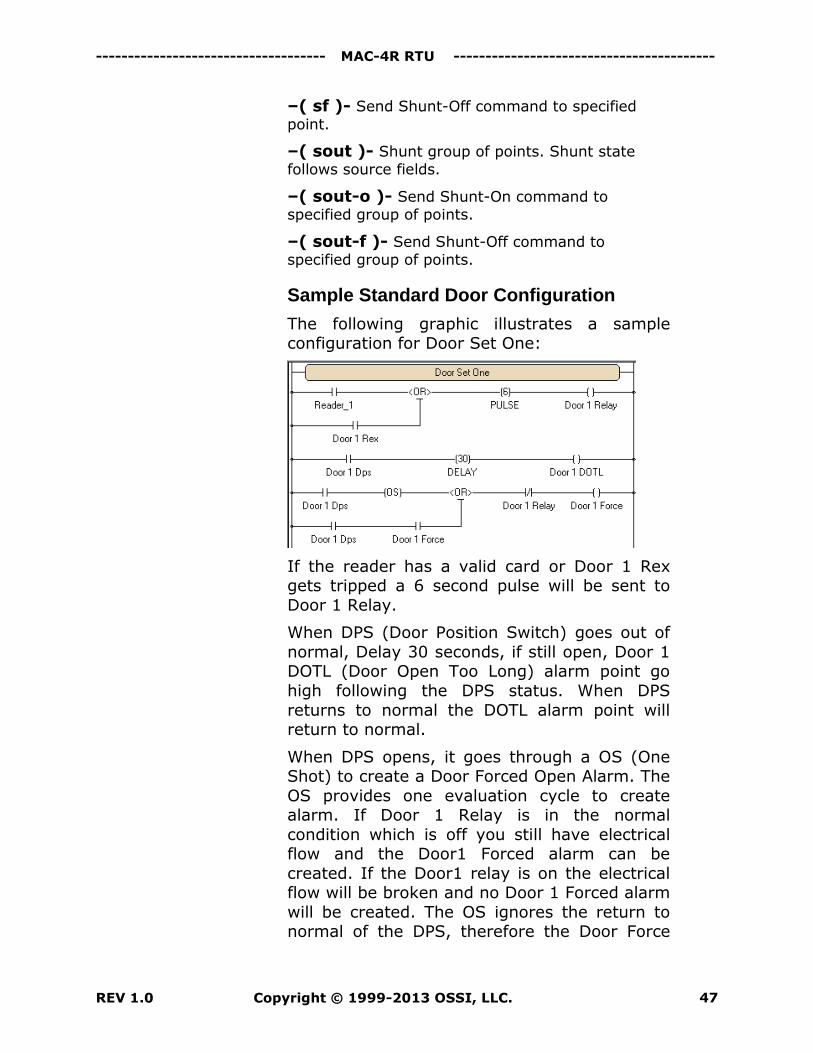
Sample Standard Door Configuration
The following graphic illustrates a sample configuration for Door Set One:
If the reader has a valid card or Door 1 Rex gets tripped a 6 second pulse will be sent to
Door 1 Relay.
When DPS (Door Position Switch) goes out of
normal, Delay 30 seconds, if still open, Door 1 DOTL (Door Open Too Long) alarm point go
high following the DPS status. When DPS
returns to normal the DOTL alarm point will return to normal.
When DPS opens, it goes through a OS (One Shot) to create a Door Forced Open Alarm. The
OS provides one evaluation cycle to create alarm. If Door 1 Relay is in the normal
condition which is off you still have electrical flow and the Door1 Forced alarm can be
created. If the Door1 relay is on the electrical flow will be broken and no Door 1 Forced alarm
will be created. The OS ignores the return to normal of the DPS, therefore the Door Force
--------------------------------- MAC-4R RTU Guide -------------------------------------- -
Copyright © 1999-2013 OSSI, LLC. REV 1.0 48
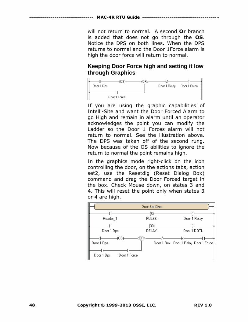
will not return to normal. A second Or branch
is added that does not go through the OS. Notice the DPS on both lines. When the DPS
returns to normal and the Door 1Force alarm is high the door force will return to normal.
Keeping Door Force high and setting it low through Graphics
If you are using the graphic capabilities of
Intelli-Site and want the Door Forced Alarm to go High and remain in alarm until an operator
acknowledges the point you can modify the Ladder so the Door 1 Forces alarm will not
return to normal. See the illustration above.
The DPS was taken off of the second rung. Now because of the OS abilities to ignore the
return to normal the point remains high.
In the graphics mode right-click on the icon
controlling the door, on the actions tabs, action set2, use the Resetdig (Reset Dialog Box)
command and drag the Door Forced target in the box. Check Mouse down, on states 3 and
4. This will reset the point only when states 3 or 4 are high.
------------------------------------ MAC-4R RTU -----------------------------------------
REV 1.0 Copyright © 1999-2013 OSSI, LLC. 49
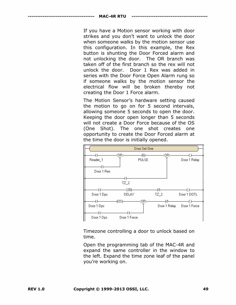
If you have a Motion sensor working with door
strikes and you don’t want to unlock the door when someone walks by the motion sensor use
this configuration. In this example, the Rex button is shunting the Door Forced alarm and
not unlocking the door. The OR branch was taken off of the first branch so the rex will not
unlock the door. Door 1 Rex was added in series with the Door Force Open Alarm rung so
if someone walks by the motion sensor the electrical flow will be broken thereby not
creating the Door 1 Force alarm.
The Motion Sensor’s hardware setting caused
the motion to go on for 5 second intervals, allowing someone 5 seconds to open the door.
Keeping the door open longer than 5 seconds
will not create a Door Force because of the OS (One Shot). The one shot creates one
opportunity to create the Door Forced alarm at the time the door is initially opened.
Timezone controlling a door to unlock based on
time.
Open the programming tab of the MAC-4R and expand the same controller in the window to
the left. Expand the time zone leaf of the panel you’re working on.
--------------------------------- MAC-4R RTU Guide -------------------------------------- -
Copyright © 1999-2013 OSSI, LLC. REV 1.0 50
Drop an Or branch after the pulse time on
Door 1 Relay rung. Then add the time zone to the branch. Because the Or is after the Pulse
command the relay will be held on for the entire time zone. If the Or branch is before the
pulse, a 6 second pulse would be sent to the relay when the time zone first started.
The Time zone should also be added to the Door 1 DOTL alarm to shunt the alarm during
the time zone. When the time zone activates it will break the electrical flow and not allow a
Door 1 DOTL alarm to be created.
Adding the Time zone to the Door 1 Forced
alarm is not necessary because the Door 1 Relay will be on during the Time zone in effect
shunting out the Door 1 Forced alarm during
the Time zone.
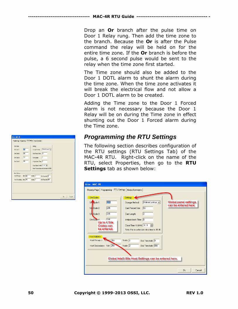
Programming the RTU Settings
The following section describes configuration of
the RTU settings (RTU Settings Tab) of the MAC-4R RTU. Right-click on the name of the
RTU, select Properties, then go to the RTU
Settings tab as shown below:
------------------------------------ MAC-4R RTU -----------------------------------------
REV 1.0 Copyright © 1999-2013 OSSI, LLC. 51
Site Codes: The site codes can be entered
individually on the card screen or globally on this screen. Intelli-Site allows up to four site
codes. A value of 255 is a valid site code for any site. If there is only one site code in the
facility that site code must be entered in all four slots. If the MAC-4R sees a 255 in any of
the slots it will still allow any site code.
Storage Method: Ordered lookup can
support up to 16,000 12 digits cards while the Flat file supports up to 52,000 5 digit cards.
Card numbers of 52,001 through 65,000 are not supported using Flat File mode. Ordered
Lookup is the default.
Card Record Size – 16 is the default size for
Card Records (Bytes).
Card Length – 2 is the default size for Card Length (Bytes).
Anti Passback Time – The panel supports timed anti-passback. Time supported is
expressed in minutes ranging from 0 to 255.
Close Time HH:MM - At the close time the
MAC-4R will clear any points that have been forced on. To disable this feature enter a value
of 0.
Host Settings – Host setting defaults should
not be changed.