MA8100A TRX Module
8
Quick Start Guide MA8100A NEON ® Signal Mapper Note You must have an Android smart phone or tablet and an Email address that you will use to sign in throughout this entire process. Basic familiarity with Anritsu handheld spectrum analyzers is required. If you need assistance with any of these steps, visit the TRX help center at: http://trxsystems.zendesk.com The latest documentation and additional support for the TRX Tracking unit and NEON Signal Mapping software can be accessed from the support site at http://www.trxsystems.com/ and selecting NEON Signal Mapping. Additional support is available from Anritsu by visiting: http://www.anritsu.com/contact-us From here, you can select the latest sales, select service and support contact information in your country or region, provide online feedback, complete a “Talk to Anritsu” form to have your questions answered, or obtain other services offered by Anritsu. Anritsu Company 490 Jarvis Drive Morgan Hill, CA 95037-2809 USA Part Number: 10580-00422 Revision: A Published: April 2016 Copyright 2016 Anritsu Company
-
Upload
nguyenhuong -
Category
Documents
-
view
226 -
download
0
Transcript of MA8100A TRX Module

Quick Start Guide
MA8100A NEON® Signal Mapper
Note
You must have an Android smart phone or tablet and an Email address that you will use to sign in throughout this entire process. Basic familiarity with Anritsu handheld spectrum analyzers is required.
If you need assistance with any of these steps, visit the TRX help center at: http://trxsystems.zendesk.com
The latest documentation and additional support for the TRX Tracking unit and NEON Signal Mapping software can be accessed from the support site at http://www.trxsystems.com/ and selecting NEON Signal Mapping.
Additional support is available from Anritsu by visiting: http://www.anritsu.com/contact-us From here, you can select the latest sales, select service and support contact information in your country or region, provide online feedback, complete a “Talk to Anritsu” form to have your questions answered, or obtain other services offered by Anritsu.
Anritsu Company490 Jarvis DriveMorgan Hill, CA 95037-2809USA
Part Number: 10580-00422Revision: A
Published: April 2016Copyright 2016 Anritsu Company

QSG-2 PN: 10580-00422 Rev. A MA8100A QSG
Installing & Registering for NEON Command (PC Software)1. Check your email for registration instructions and set up a NEON account.
2. Download the NEON Command software from the Downloads tab on the customer portal website(your web browser may warn you that this file is unsafe).
3. Install NEON Command by following the installation wizard.
a. Windows might ask you if you want to allow the installation. If it does, select Run Anyway.
b. Start NEON Command will be selected by default.
c. If the installation is successful, the NEON Command window will appear showing the map.
4. Sign in by clicking No User Logged In in the upper right corner.
a. Log in by entering your email and password, or with a Gmail account.
b. If you log in with Gmail, you will be redirected to a web page that prompts you to allow permissions for NEON.
c. Click Allow to complete the sign-in process.
d. Verify that the indicator turns green in the upper right corner.
Installing NEON Signal Mapper (Android) You will need to have your NEON account login, an Android phone, and the TRX Tracking unit. Refer to the instructions that came with your TRX tracking unit to set up the tracking device and to install the Android software. Documentation and additional support can be accessed from the support site at: http://www.trxsystems.com/ and selecting NEON Signal Mapping. Software can be downloaded from: https://neon.trxsystems.com/downloads/nls.

MA8100A QSG PN: 10580-00422 Rev. A QSG-3
NEON Command OverviewNEON Command provides a map or satellite view of your testing area with tools for creating buildings and other features. The following provide a basic overview of the software and its controls.
1. Use the Signal Mapping menu to:
2. Use the Map Data menu to:
3. Use the Building Editor menu to:
4. Use the Personnel side menu to:
• Create a new signal map
• Open an existing signal log data file from a local drive or the cloud
• Export all signal log data to a local folder
• Delete the log data from the cloud server
• Close the signal mapping log data file
• Import an existing building shape file
• Refresh mapping
• Select the base map style (None, Satellite, Map, Hybrid, or Terrain)
• Toggle map detail layers (such as personal trails, labels, buildings, terrain, etc.)
• Deselect a building
• Create building outlines
• Edit or delete building outlines
• Create building floor levels and set the floor spacing
• Add floor plan detail images
• Select signal types and signal mapping data log
• Generate signal heat maps and customize the color settings
1
2
3
4
QSG-4 PN: 10580-00422 Rev. A MA8100A QSG
Site Planning (PC)1. Open the NEON Command software and center on the building that you want to map.
a. Click the search icon located on the top right corner of the map.
b. When a text input box appears, enter the address of the location that you wish to map.
c. Press Enter to validate the address.
d. If successful, the map will be centered on the given location.
e. You can drag and zoom using the mouse to move around the map.
2. Create a simple building outline. Note that the Building Editor menu items are disabled when a signal map is currently open. Close a currently open signal map from the Signal Mapping menu and then click New.
a. Click the Building Editor tab in the top bar and then click Create Outline.
b. Click on the map to set vertices of the building outline and then press Enter when done, or select End Outline Creation.
c. Click Begin Edit to enable the floor plan tools.
d. Using the floor plan tools, add floors above or below, and set the level height (between floors). Click Add Above to add a floor above the selected one. If you want to add a basement floor, click Floor 1 in the elevation sidebar, and then click Add Below.
e. Click Floor Plan to load an image file with floor plan features and use the mouse to drag the position and size of the image for best fit.
f. To edit a building outline, right click a building and then select Building Outline > Edit from the pop-up dialog. The building outline menu provides the following controls:
• Translate and Scale
• Move Vertex
• Add Polygon
• Add Vertex
• Delete Vertex
• Remove Polygon
f
e
a
b
c
d
g
h
MA8100A QSG PN: 10580-00422 Rev. A QSG-5
g. To edit a building floor plan, select the level you wish to edit from the right side of the map, right click a building, and then select Floor Plan > Edit from the pop-up dialog. The floor plan menu provides the following controls:
Click and drag the green circle to rotate the floor plan image. Click and drag the purple circle on the corner of the floor plan to scale the image. Press the Esc key to close the floor plan tools.
h. Click the End Edit button, then click Yes in the resulting pop up to save your changes. If you are signed in, the building model will be saved to your NEON account on the cloud.
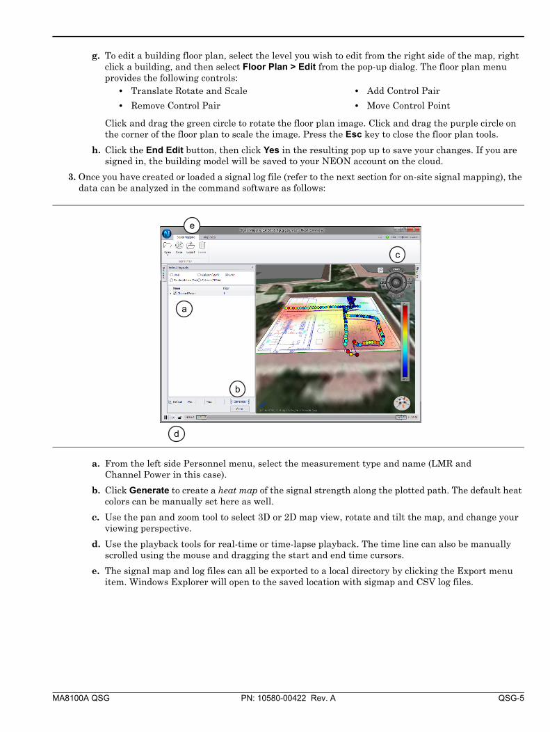
3. Once you have created or loaded a signal log file (refer to the next section for on-site signal mapping), the data can be analyzed in the command software as follows:
a. From the left side Personnel menu, select the measurement type and name (LMR and Channel Power in this case).
b. Click Generate to create a heat map of the signal strength along the plotted path. The default heat colors can be manually set here as well.
c. Use the pan and zoom tool to select 3D or 2D map view, rotate and tilt the map, and change your viewing perspective.
d. Use the playback tools for real-time or time-lapse playback. The time line can also be manually scrolled using the mouse and dragging the start and end time cursors.
e. The signal map and log files can all be exported to a local directory by clicking the Export menu item. Windows Explorer will open to the saved location with sigmap and CSV log files.
• Translate Rotate and Scale
• Remove Control Pair
• Add Control Pair
• Move Control Point
a
c
d
e
b

QSG-6 PN: 10580-00422 Rev. A MA8100A QSG
On Site Signal Mapping with Anritsu Handheld Instrument1. Connect the Anritsu Handheld instrument to your Android device via the provided USB OTG cable.
2. Set the Anritsu Handheld instrument for Spectrum Analyzer mode.
3. Set up a Channel Power measurement for your desired measurement.
4. Turn on the Tracking Unit by pressing the power button .
• A green LED will start blinking on the Tracking Unit (If a blue LED is blinking, you already paired the device).
5. Open the NEON Personnel Tracker app on the Android smart phone.
6. Log in with your NEON account.
a. Click on the menu icon to access the location settings.
b. Click Log In, then select or add your NEON account. Your account will appear and the text will update to Log Out.
Note Make sure to turn on the Channel Power measurement.
MA8100A QSG PN: 10580-00422 Rev. A QSG-7
7. Pair the tracking unit and the phone by touching the TRX Logo on the Tracking Unit to your NFC enabled Android smart phone.
8. Accept the pairing request if prompted. The LED will blink blue instead of green when pairing is successful.
9. Attach the tracking unit to your waist using the belt clip.
10. Enable Tracking, then press the Back button to return to the Personnel Tracker app.
11. Initialize your location with GPS or with manual check-ins. The initialization method depends on your use case.
a. To initialize with GPS, walk outside at least 10 meters from the building.
b. To initialize manually, press the check-in icon and then move the map to place the green marker at your current location.
c. Press the check mark in the upper right corner to complete the check-in.
12. Center on your location by pressing the center icon .
13. Select your building with a long press.
• The building will turn white and the floor plans should appear when it is selected.
• If the building does not appear, press the synchronize button .
14. Select the floor that you are currently on using the floor selector on the right of the screen.
15. Calibrate the signal tracker.
a. Initialize your position by pressing the check-in icon and then move the map to place the green marker at your current location.
b. Walk at least 10 meters and press the check-in icon again to complete the calibration.
16. Walk around and take your measurements. Your location will be automatically tracked!
NoteYou may have to move the Tracking Unit around to align its NFC tag with the phone's NFC tag and you may need to disable tracking in order to pair the tracking unit.

Anritsu utilizes recycled paper and environmentally conscious inks and toner.
Anritsu Company490 Jarvis Drive
Morgan Hill, CA 95037-2809USA
http://www.anritsu.com