MA4757-L Charging on from Schematics to Panels in...
18
Charging on from Schematics to Panels in AutoCAD ® Electrical Todd Schmoock – Synergis Technologies MA4757-L: You have been using AutoCAD ® Electrical and discovered it is an easy tool for creating electrical controls system designs, but what do you do now that your electrically smart schematics are done? How do you create the smart panel to go along with the smart schematics? In this lab you will take an AutoCAD ® Electrically smart schematic control system design and create the AutoCAD ® Electrical smart panel. you will extract the information from the schematic drawing to create the panel drawing. Additionally, you will see how to utilize the reporting functionality by extracting the information from the newly created panel drawing. Most importantly, you will do all this with tools available in a typical installation of AutoCAD ® Electrical! Learning Objectives At the end of this class, you will be able to: Add a table and catalog data to the default_cat.mdb file Create a custom panel symbol (Footprint) Add an entry to the footprint_lookup.mdb file o Add part number to the panel database Create a panel drawing from the electrical smart schematic drawing Execute bi-directional updates between schematic and panel layout Run panel reports About the Speaker: Todd is a Solutions Engineer with Synergis Technologies. He has over 25 years of Drafting, Design, and CAD experience in manufacturing environment using AutoCAD ® , Mechanical Desktop, and Inventor and is a certified Inventor Expert. Prior to joining Synergis Todd worked in several fields, including technical ceramic, elevator, and specialty gas industries, and government contract work requiring strict drafting standards. Todd has presented classes at the past three Autodesk University conferences. [email protected]
Transcript of MA4757-L Charging on from Schematics to Panels in...

Charging on from Schematics to Panels in AutoCAD® Electrical Todd Schmoock – Synergis Technologies
MA4757-L: You have been using AutoCAD® Electrical and discovered it is an easy tool for creating electrical controls system designs, but what do you do now that your electrically smart schematics are done? How do you create the smart panel to go along with the smart schematics? In this lab you will take an AutoCAD® Electrically smart schematic control system design and create the AutoCAD® Electrical smart panel. you will extract the information from the schematic drawing to create the panel drawing. Additionally, you will see how to utilize the reporting functionality by extracting the information from the newly created panel drawing. Most importantly, you will do all this with tools available in a typical installation of AutoCAD® Electrical!
LearningObjectivesAt the end of this class, you will be able to:
Add a table and catalog data to the default_cat.mdb file
Create a custom panel symbol (Footprint)
Add an entry to the footprint_lookup.mdb file
o Add part number to the panel database
Create a panel drawing from the electrical smart schematic drawing
Execute bi-directional updates between schematic and panel layout
Run panel reports
About the Speaker:
Todd is a Solutions Engineer with Synergis Technologies. He has over 25 years of Drafting, Design, and CAD experience in manufacturing environment using AutoCAD®, Mechanical Desktop, and Inventor and is a certified Inventor Expert. Prior to joining Synergis Todd worked in several fields, including technical ceramic, elevator, and specialty gas industries, and government contract work requiring strict drafting standards. Todd has presented classes at the past three Autodesk University conferences.

Charging on from Schematics to Panels in AutoCAD® Electrical
2

Charging on from Schematics to Panels in AutoCAD® Electrical
3
GettingStarted:You have been working with AutoCAD® Electrical for some time now and you are comfortable creating schematics. Included in the schematics are smart symbols you created using the Symbol Builder. After running the Project-Wide Update or Retag tool everything updates as expected, and you run the Electrical Audit and no errors are reported. However, you still create the panel drawings using standard AutoCAD® commands because you do not know how to link your custom symbols to the panel footprints. This class will add a database entry for a custom schematic symbol, create a panel footprint, add and entry to the panel database to link the schematic symbol, extract the information from the schematic drawing to create the panel drawing, execute bi-directional updates to verify the schematic and panel drawing update, and we will end by running a panel report.
ActivatetheAutoCAD®Electricalproject:1. Open the MA4757-L AutoCAD® Electrical project. Autodesk has a folder location for all
AU datasets. Look for a folder called MA4757-L. Inside the folder will be a file named MA4757-L.wdp which is the AutoCAD® Electrical project file for this class.
2. Double-click the project in the project manager to expand the drawings associated with the project.
3. Open drawing "Interface Module Schematic Drawing".
A custom symbol has been created for a Banner IM-T-9A Interface Module:
Charging on from Schematics to Panels in AutoCAD® Electrical
4
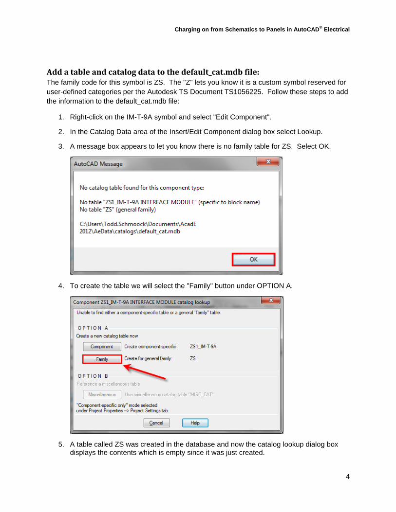
Addatableandcatalogdatatothedefault_cat.mdbfile:The family code for this symbol is ZS. The "Z" lets you know it is a custom symbol reserved for user-defined categories per the Autodesk TS Document TS1056225. Follow these steps to add the information to the default_cat.mdb file:
1. Right-click on the IM-T-9A symbol and select "Edit Component".
2. In the Catalog Data area of the Insert/Edit Component dialog box select Lookup.
3. A message box appears to let you know there is no family table for ZS. Select OK.
4. To create the table we will select the "Family" button under OPTION A.
5. A table called ZS was created in the database and now the catalog lookup dialog box displays the contents which is empty since it was just created.

Charging on from Schematics to Panels in AutoCAD® Electrical
5
6. In the upper left-hand corner of the dialog you will find 4 tools which allow you to display additional information, clear filters, create a new record, or edit a record. Click the Add button since this will be the first entry for this record:
7. The Add Catalog Record (table ZS) displays allowing you to had the needed information for the catalog number. We will only be adding the required information designated by the bold text and the * at the end.
8. Fill in the following information and select OK:
9. Save the drawing.
You now have a schematic symbol with a catalog number. The manufacturer and the catalog number will be used to link the schematic symbol to the footprint. In this case the manufacturer is Banner, and the catalog number is IM-T-9A.
Charging on from Schematics to Panels in AutoCAD® Electrical
6
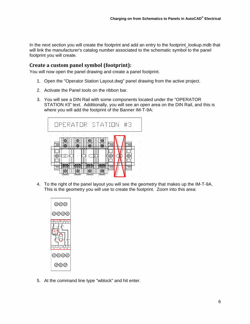
In the next section you will create the footprint and add an entry to the footprint_lookup.mdb that will link the manufacturer's catalog number associated to the schematic symbol to the panel footprint you will create.
Createacustompanelsymbol(footprint):You will now open the panel drawing and create a panel footprint.
1. Open the "Operator Station Layout.dwg" panel drawing from the active project.
2. Activate the Panel tools on the ribbon bar.
3. You will see a DIN Rail with some components located under the "OPERATOR STATION #3" text. Additionally, you will see an open area on the DIN Rail, and this is where you will add the footprint of the Banner IM-T-9A:
4. To the right of the panel layout you will see the geometry that makes up the IM-T-9A. This is the geometry you will use to create the footprint. Zoom into this area:
5. At the command line type "wblock" and hit enter.
Charging on from Schematics to Panels in AutoCAD® Electrical
7
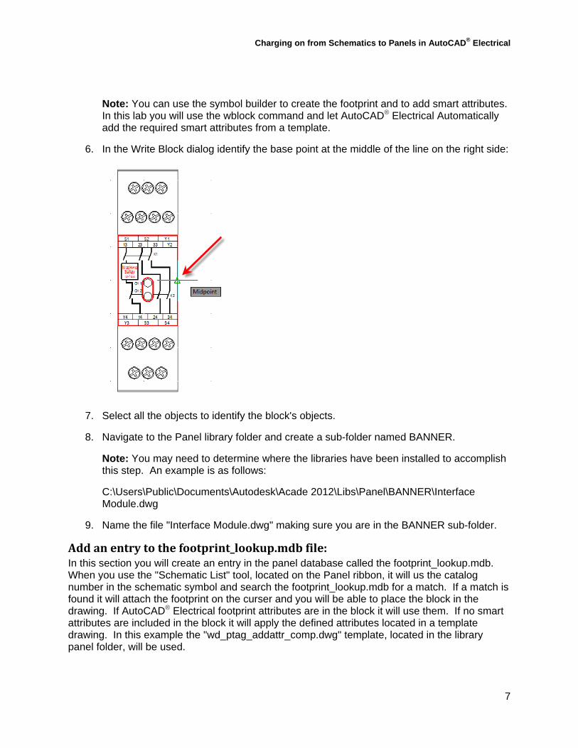
Note: You can use the symbol builder to create the footprint and to add smart attributes. In this lab you will use the wblock command and let AutoCAD® Electrical Automatically add the required smart attributes from a template.
6. In the Write Block dialog identify the base point at the middle of the line on the right side:
7. Select all the objects to identify the block's objects.
8. Navigate to the Panel library folder and create a sub-folder named BANNER.
Note: You may need to determine where the libraries have been installed to accomplish this step. An example is as follows:
C:\Users\Public\Documents\Autodesk\Acade 2012\Libs\Panel\BANNER\Interface Module.dwg
9. Name the file "Interface Module.dwg" making sure you are in the BANNER sub-folder.
Addanentrytothefootprint_lookup.mdbfile:In this section you will create an entry in the panel database called the footprint_lookup.mdb. When you use the "Schematic List" tool, located on the Panel ribbon, it will us the catalog number in the schematic symbol and search the footprint_lookup.mdb for a match. If a match is found it will attach the footprint on the curser and you will be able to place the block in the drawing. If AutoCAD® Electrical footprint attributes are in the block it will use them. If no smart attributes are included in the block it will apply the defined attributes located in a template drawing. In this example the "wd_ptag_addattr_comp.dwg" template, located in the library panel folder, will be used.
Charging on from Schematics to Panels in AutoCAD® Electrical
8
To add an entry to the footprint_lookup.mdb database file you will follow these steps:
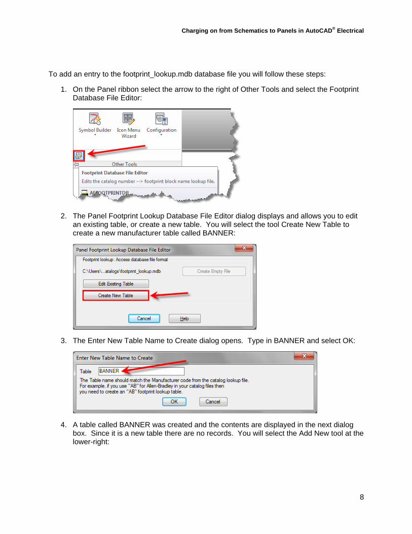
1. On the Panel ribbon select the arrow to the right of Other Tools and select the Footprint Database File Editor:
2. The Panel Footprint Lookup Database File Editor dialog displays and allows you to edit an existing table, or create a new table. You will select the tool Create New Table to create a new manufacturer table called BANNER:
3. The Enter New Table Name to Create dialog opens. Type in BANNER and select OK:
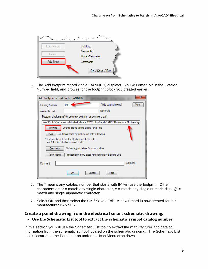
4. A table called BANNER was created and the contents are displayed in the next dialog box. Since it is a new table there are no records. You will select the Add New tool at the lower-right:
Charging on from Schematics to Panels in AutoCAD® Electrical
9
5. The Add footprint record (table: BANNER) displays. You will enter IM* in the Catalog Number field, and browse for the footprint block you created earlier:
6. The * means any catalog number that starts with IM will use the footprint. Other characters are ? = match any single character, # = match any single numeric digit, @ = match any single alphabetic character.
7. Select OK and then select the OK / Save / Exit. A new record is now created for the manufacturer BANNER.
Createapaneldrawingfromtheelectricalsmartschematicdrawing. UsetheSchematicListtooltoextracttheschematicsymbolcatalognumber:
In this section you will use the Schematic List tool to extract the manufacturer and catalog information from the schematic symbol located on the schematic drawing. The Schematic List tool is located on the Panel ribbon under the Icon Menu drop down.
Charging on from Schematics to Panels in AutoCAD® Electrical
10
To extract the catalog information from the schematic drawing follow these steps:
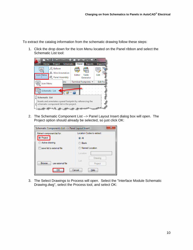
1. Click the drop down for the Icon Menu located on the Panel ribbon and select the Schematic List tool:
2. The Schematic Component List --> Panel Layout Insert dialog box will open. The Project option should already be selected, so just click OK:
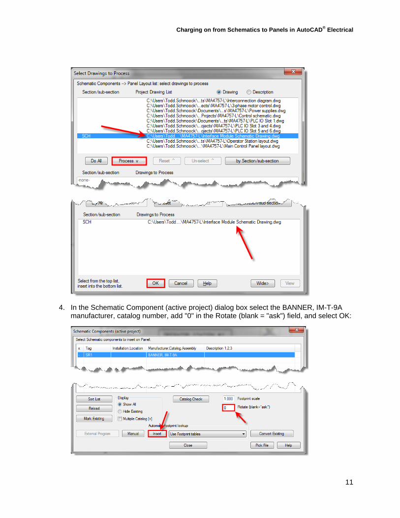
3. The Select Drawings to Process will open. Select the "Interface Module Schematic Drawing.dwg", select the Process tool, and select OK:
Charging on from Schematics to Panels in AutoCAD® Electrical
11
4. In the Schematic Component (active project) dialog box select the BANNER, IM-T-9A manufacturer, catalog number, add "0" in the Rotate (blank = "ask") field, and select OK:
Charging on from Schematics to Panels in AutoCAD® Electrical
12
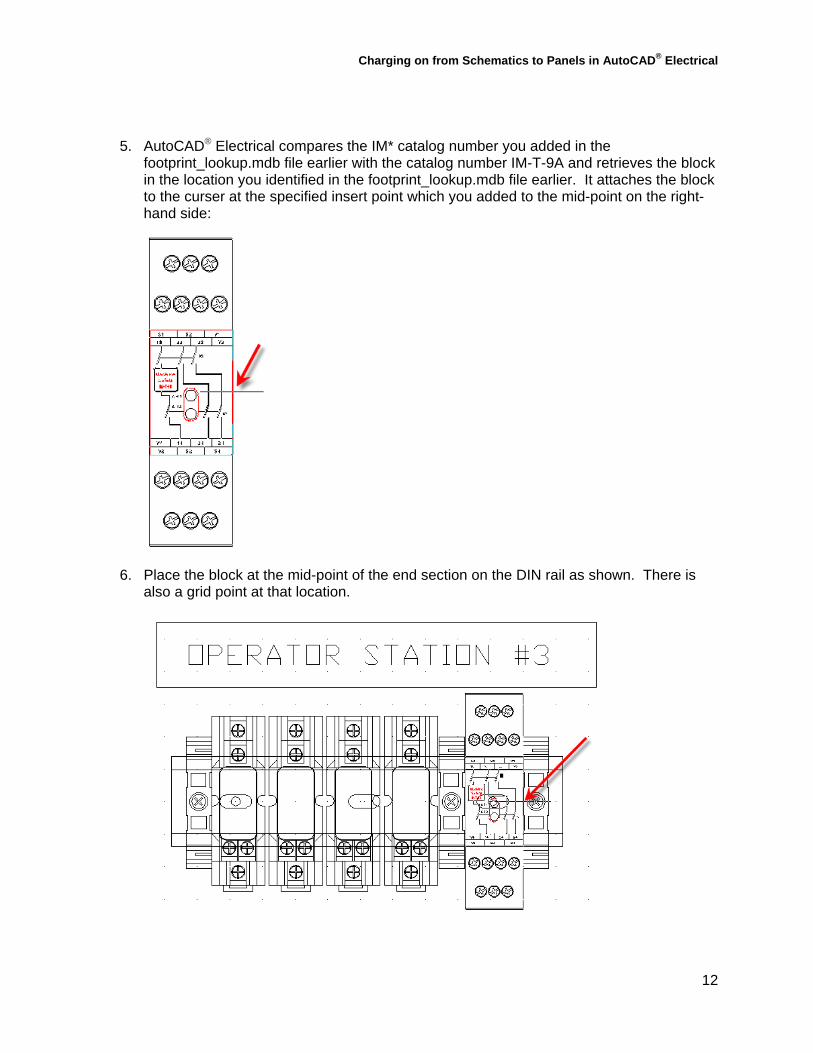
5. AutoCAD® Electrical compares the IM* catalog number you added in the footprint_lookup.mdb file earlier with the catalog number IM-T-9A and retrieves the block in the location you identified in the footprint_lookup.mdb file earlier. It attaches the block to the curser at the specified insert point which you added to the mid-point on the right-hand side:
6. Place the block at the mid-point of the end section on the DIN rail as shown. There is also a grid point at that location.

Charging on from Schematics to Panels in AutoCAD® Electrical
13
7. The Panel Layout - Component Insert/Edit dialog box opens. Click the Next>> button in the Item Number section at the upper-right to assign 1 as the item number.
8. Click OK in the Panel Layout - Component Insert/Edit dialog box, and Close in the Schematic Component (active project) dialog box.
9. Click OK in the Update other drawings dialog box? and the QSAVE dialog box.
10. AutoCAD Electrical opens the Interface Module Schematic Drawing.dwg to update it, saves it, and then closes it.
Executebi‐directionalupdatesbetweenschematicandpanellayout:In this section you will Execute bi-directional updates between the schematic and panel layout to verify the schematic symbol and the panel footprint are linked together. To do this you will edit the footprint component you just added using the Edit Footprint tool and add a description.
To add a description to the footprint and force a bi-directional update follow these steps:
1. Right-click on the footprint symbol you added in the last section and select Edit Footprint:

Charging on from Schematics to Panels in AutoCAD® Electrical
14
2. In the Panel Layout - Component Insert/Edit dialog box enter INTERFACE MODULE in the Description field as shown:
3. Select OK.
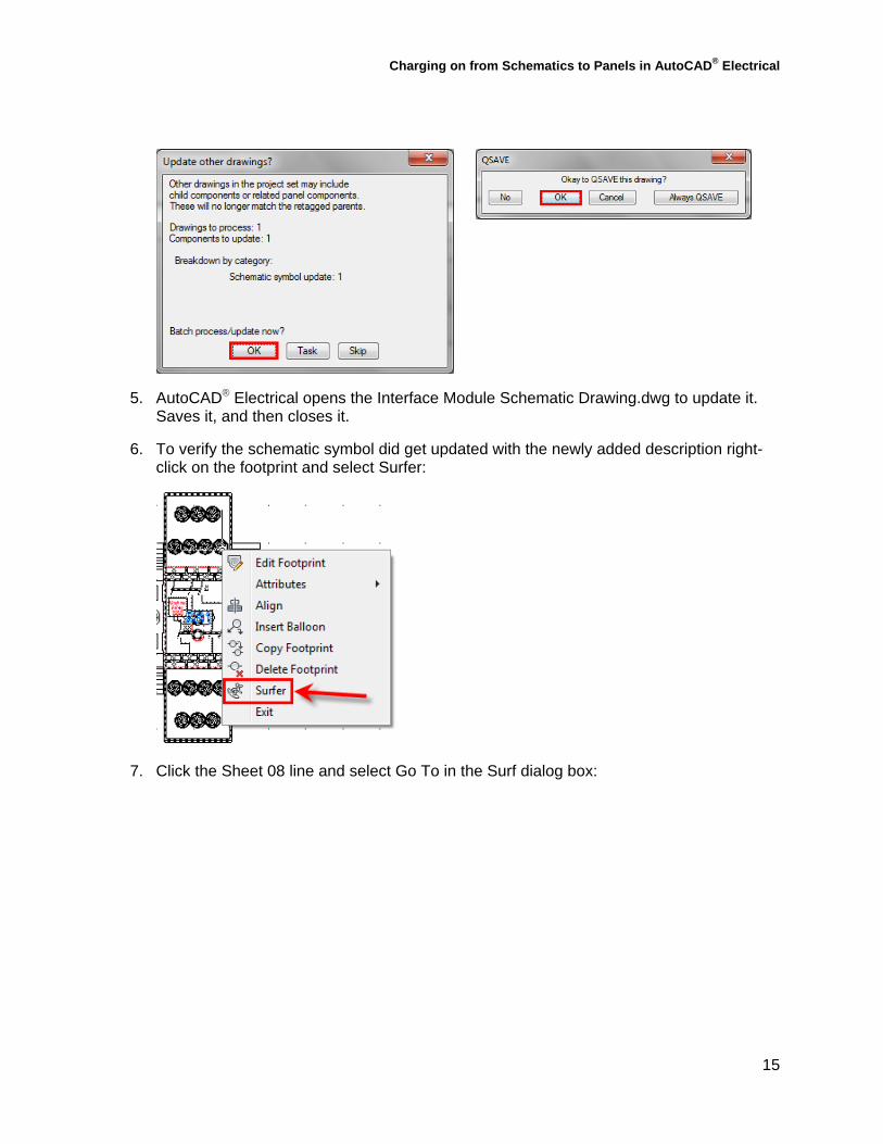
4. Click OK in the Update other drawings dialog box? and the QSAVE dialog box.
Charging on from Schematics to Panels in AutoCAD® Electrical
15
5. AutoCAD® Electrical opens the Interface Module Schematic Drawing.dwg to update it. Saves it, and then closes it.
6. To verify the schematic symbol did get updated with the newly added description right-click on the footprint and select Surfer:
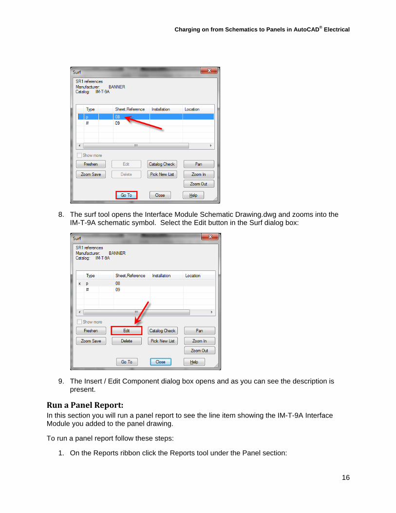
7. Click the Sheet 08 line and select Go To in the Surf dialog box:
Charging on from Schematics to Panels in AutoCAD® Electrical
16
8. The surf tool opens the Interface Module Schematic Drawing.dwg and zooms into the IM-T-9A schematic symbol. Select the Edit button in the Surf dialog box:
9. The Insert / Edit Component dialog box opens and as you can see the description is present.
RunaPanelReport:In this section you will run a panel report to see the line item showing the IM-T-9A Interface Module you added to the panel drawing.
To run a panel report follow these steps:
1. On the Reports ribbon click the Reports tool under the Panel section:

Charging on from Schematics to Panels in AutoCAD® Electrical
17
2. When the Panel Reports dialog box opens Bill of Material will be selected by default, and to the right of it select the option for Active drawing:
3. Select OK.
4. AutoCAD® Electrical extracts the catalog information from the drawing and sorts the information based on the item number. If your results are sorted on the item number see the next step.
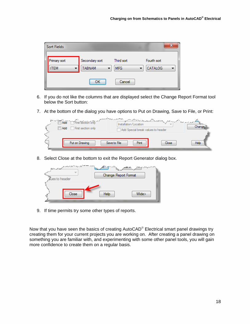
5. To see why it sorted the items based on the item numbers select the Sort tool at the lower-right of the dialog box. As you can see, the Primary sort option is set to ITEM. If your Primary sort is not set to ITEM select the drop down arrow and set it to ITEM:
Charging on from Schematics to Panels in AutoCAD® Electrical
18
6. If you do not like the columns that are displayed select the Change Report Format tool below the Sort button:
7. At the bottom of the dialog you have options to Put on Drawing, Save to File, or Print:
8. Select Close at the bottom to exit the Report Generator dialog box.
9. If time permits try some other types of reports.
Now that you have seen the basics of creating AutoCAD® Electrical smart panel drawings try creating them for your current projects you are working on. After creating a panel drawing on something you are familiar with, and experimenting with some other panel tools, you will gain more confidence to create them on a regular basis.