Ma105 1 l mather
39
1 Becoming an Autodesk Inventor® Professor in 90 Minutes J.D. Mather – Pennsylvania College of Technology MA105-1L Looking for that one tip that will justify trip to AU. If you’re an intermediate Inventor user, then you’ll find it here. This session offers a fast-paced delivery of productivity tips and problem-solving strategies gained from teaching hundreds of students how to use Inventor. If your co- workers don’t call you the Inventor Professor after this class you should consider another major! About the Speaker: Dr. Mather is an assistant professor of CAD and Product Design at Pennsylvania College of Technology affiliate of Penn State University. He has taught AutoCAD courses for 13 years and has been an Autodesk Inventor Certified Expert since release 7. His advanced 3D Modeling tutorials are studied by users around the world. http://home.pct.edu/~jmather/content/DSG322/inventor_surface_tutorials.htm Previously he worked in industry for 15 years, including positions as Journeyman Machinist, Research & Development Technician and Industrial Engineering Technician. http://home.pct.edu/~jmather/AU2007/MA105-1L%20Mather.pdf http://home.pct.edu/~jmather/AU2007/MA105-1L%20Dataset.zip [email protected]
-
Upload
bejn-penik -
Category
Technology
-
view
267 -
download
2
Transcript of Ma105 1 l mather

1
Becoming an Autodesk Inventor® Professor in 90
Minutes J.D. Mather – Pennsylvania College of Technology
MA105-1L Looking for that one tip that will justify trip to AU. If you’re an intermediate Inventor user,
then you’ll find it here. This session offers a fast-paced delivery of productivity tips and problem-solving strategies gained from teaching hundreds of students how to use Inventor. If your co-workers don’t call you the Inventor Professor after this class you should consider another major!
About the Speaker:
Dr. Mather is an assistant professor of CAD and Product Design at Pennsylvania College of Technology
affiliate of Penn State University. He has taught AutoCAD courses for 13 years and has been an
Autodesk Inventor Certified Expert since release 7. His advanced 3D Modeling tutorials are studied by
users around the world.
http://home.pct.edu/~jmather/content/DSG322/inventor_surface_tutorials.htm
Previously he worked in industry for 15 years, including positions as Journeyman Machinist, Research &
Development Technician and Industrial Engineering Technician.
http://home.pct.edu/~jmather/AU2007/MA105-1L%20Mather.pdf
http://home.pct.edu/~jmather/AU2007/MA105-1L%20Dataset.zip

2
Becoming an Autodesk Inventor® Professor in 90 Minutes
Setting up the Environment
Before we get into the class proper, we need to do some housekeeping so that we are all using
the same “keyboard” (user interface).
Sketching is the foundation of Inventor. I am pretty particular about how I set up the sketch
environment.
o 1. I turn off the Grid Lines. I like the clean screen graphics window. In Inventor we use a sketching technique rather than the direct distance entry technique of AutoCAD. The rough equivalent workflow in Inventor is achieved if you
o 2. Checkmark the Edit dimension when created box.
o 3. Uncheck the Autoproject edges for sketch creation and edit. (I’ll explain why later. A new option in Inventor 11 is the Autoproject part origin on sketch create. I like to
think Autodesk included this feature just for me after several years of persistent
requests. (Thanks go to Neil Munro for the precursor add-in.)
o 4. Checkmark the Autoproject part origin on sketch create.
1
2
3
4
Assistants – we will jump ahead to
#7 and have the students Import
these settings. (New in r2008)

3
Becoming an Autodesk Inventor® Professor in 90 Minutes
o 5. On the Assembly tab uncheck Constraint Audio Notification or change the Program Files\Autodesk\Inventor 2008\Bin\Connect.wav file to something really cool.
o 6. For projection in a training classroom the Sky Color Scheme seems to give the best contrast.
5
4
Becoming an Autodesk Inventor® Professor in 90 Minutes
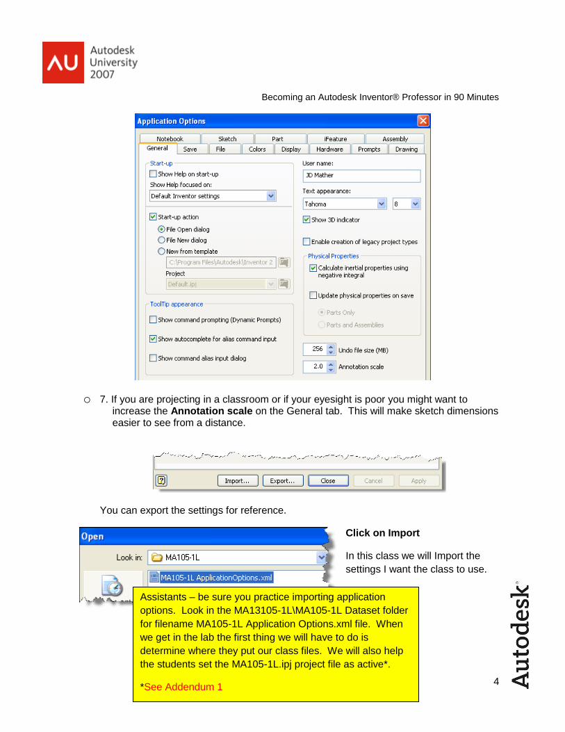
o 7. If you are projecting in a classroom or if your eyesight is poor you might want to increase the Annotation scale on the General tab. This will make sketch dimensions easier to see from a distance.
You can export the settings for reference.
Click on Import
In this class we will Import the
settings I want the class to use.
Assistants – be sure you practice importing application
options. Look in the MA13105-1L\MA105-1L Dataset folder
for filename MA105-1L Application Options.xml file. When
we get in the lab the first thing we will have to do is
determine where they put our class files. We will also help
the students set the MA105-1L.ipj project file as active*.
*See Addendum 1

5
Becoming an Autodesk Inventor® Professor in 90 Minutes
Sketching is the Foundation
In this class I will use the using the Base Orphan Reference Node (BORN) Technique.
o 8. Expand the Origin folder and RMB turn on the visibility of the Center Point.
Use the origin geometry to your
advantage. It has no parents and
cannot be deleted. It will always
be there for you. Use it to anchor
your work. Use it for symmetry.
Use it for consistency. You don’t
have to have it visible to use it.
Just Use it!
o 9. Create your first line, circle, rectangle or polygon and dimension it immediately. This will give you a sense of scale for the rest of you sketch. This step is particularly important for AutoCAD users new to Inventor who are used to using direct distance entry. As we start adding constraints your sketch could get very difficult to control if it isn’t to a relative scale. We can avoid perhaps the biggest frustration for AutoCAD users’ right here.
o 10. If your origin is projected you should get a green coincident “hard snap” to the origin centerpoint. If it is not projected it might appear to snap, but this is really a “soft snap” that does not result in a constraint.
Assistants – we will skip ahead to #25, but make sure you
understand #8-24. I will only make quick reference to these
as basic techniques that everyone should know.

6
Becoming an Autodesk Inventor® Professor in 90 Minutes
o 11. After adding a dimension the sketch line changes color indicating a fully constrained sketch (the actual color change depends on your background color scheme – for printing this document I used the white presentation background, but I would normally use the sky background in a classroom). An implied coincident constraint was added when we snapped to the projected origin center point and an implied horizontal constraint was added when we clicked the endpoint for the line tracking in a horizontal direction.
o 12. If you need to select the sketch or part of the sketch you can use a crossing window or window selection.
o 13. I often use a vertical or horizontal line of symmetry. I create the line close to the origin and then add a coincident constraint between the midpoint of the line and the projected origin.
o 14. A rectangular shape is a common starting point for a model. One option is to simply start one corner of the rectangle at the projected origin. (From here on I will simply refer to the origin – it is assumed that you will ALWAYS project it.)
o 15. Coming from an AutoCAD background I used to always use this method as I frequently create Rapid Prototype models from stl files. In AutoCAD if your model isn’t in the positive xyz octant you get errors trying to export the stl file. In Inventor this is not a problem. Inventor will place the geometry in the positive octant when saving as a stl file. Tip: Inventor 2008 now allows you to save an assembly file to stl format. In previous releases you would have had to derive the assembly into a single part.

7
Becoming an Autodesk Inventor® Professor in 90 Minutes
o 16. Putting the corner of a rectangle at the origin does not, however, make the best use of the origin geometry for symmetry. Some modelers apply horizontal and vertical constraints between the midpoints and the origin.
o 17. You could use bisecting construction lines as a visual indication that can’t be missed later on if the sketch needs editing. (Remember back on the drawing board when you were instructed to not erase construction lines?)
o 18. Notice that I prefer to dimension from side to side rather than single lines as that method picks the endpoints which could be easily lost in editing.
o 19. The problem with using midpoint coincident constraints is that they can shift.
o 20. Tip: Did you notice when I created the fillet I selected the corner instead of two edges. Either way works for fillets and chamfers when there are only two edges at the intersection.

8
Becoming an Autodesk Inventor® Professor in 90 Minutes
o 21. My favorite method of starting a basically rectangular shape is to use a diagonal construction line constrained at the midpoint.
o 22. Anytime you are not sure how a sketch will react, click and drag corners. Very Important Tip: This is the easiest way to figure out the remaining constraints or dimensions that are needed to fully constrain a sketch. If you are training others make sure demonstrate this.
o 23. Many books and trainers emphasize using the Auto Dimension command for help in figuring out the remaining constraints or dimensions that are needed to fully constrain a sketch. However, I don’t think this helps in understanding geometry. In r2008 the information is also available at the lower right hand corner of the screen.
o 24. Sometimes implied constraints can be a nuisance. What if I don’t want this line constrained parallel, horizontal or perpendicular. You can override automatic placement of constraints by holding the Ctrl key.
o 25. Here is an interesting tip. I can’t create a line to the midpoint of an arc even if I RMB and choose the Midpoint option, but I can add a coincident constraint to the midpoint.

9
Becoming an Autodesk Inventor® Professor in 90 Minutes
o 26. Tip: You can set up keys for shortcuts to commonly used sketch constraints. I like to use Num . (numerical keypad period) for Coincident, Num – for Horizontal, Num + for Perpendicular, Num * for Tangent and Num / for Vertical. These work well as a mnemonic (memory aide) because “.” is a point for coincident, “-“ is horizontal, “+” is two perpendicular lines, “*” reminds me of a circle and “/” is an almost vertical line.
Notice that we can Export and Import these preferences. Unfortunately these preferences are
slow to load.
There are many pre-defined shortcuts, for example X for Trim and once in the trim command if
you hold Shift you can Extend.
Assistants – we will set up these 2D sketch constraints.
Tools>Customize>Keyboard tab
Make sure you know how to change the Categories to
Sketch and practice changing the shortcuts.
10
Becoming an Autodesk Inventor® Professor in 90 Minutes
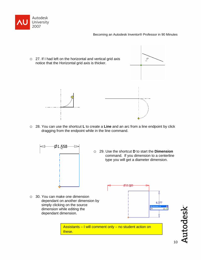
o 27. If I had left on the horizontal and vertical grid axis notice that the Horizontal grid axis is thicker.
o 28. You can use the shortcut L to create a Line and an arc from a line endpoint by click dragging from the endpoint while in the line command.
o 29. Use the shortcut D to start the Dimension command. If you dimension to a centerline type you will get a diameter dimension.
o 30. You can make one dimension dependant on another dimension by simply clicking on the source dimension while editing the dependant dimension.
Assistants – I will comment only – no student action on
these.

11
Becoming an Autodesk Inventor® Professor in 90 Minutes
o 31. Use List Parameters and set dimensions to predefined variables.
You can use units (in, mm) PI and functions in
formulas. Your formula is not lost after
accepting.
o 32. If you leave Autoproject for sketch creation turned on you can get unnecessarily complex sketches.
o 33. Don’t forget the 3-point rectangle tool. It can come in very handy. The lines are created with perpendicular constraints. If there are other autoconstraints that you don’t want, simply hold the Ctrl key while sketching.
o 34. When offsetting an ellipse you will get different results depending on whether one of the axis is highlighted or not.
Assistants – I will comment only – no student action on
these.

12
Becoming an Autodesk Inventor® Professor in 90 Minutes
o 35. RMB to get additional options when Offset.
o 36. If you have Loop Select turned off you will have to RMB Continue to offset a circle or ellipse. Watch out for this one.
o 37. Autoproject edges can cause difficulty in selecting text sketches, but you can use the Select Other tool to get the text.
o 38. Often you will want to create text sketch on an offset workplane. A workplane has a front side and a back side. The backside is a darker color. Notice that the text is placed right-reading on the front side.
Assistants – I will comment only – no student action on
these.

13
Becoming an Autodesk Inventor® Professor in 90 Minutes
o 39. You can Flip Normal (the vector perpendicular to the front side of the workplane) by RMB on the plane.
o 40. Whenever you place sketch text you should immediately dimension the text box. (The actual dimension values don’t matter).
o 41. You can then grab and drag the lower left corner to roughly reorient and then constrain just like any other sketch geometry.
o 42. A Projected Loop is created by selecting a face with the Project Geometry tool rather than selecting individual edges. I would recommend not using projected loops. For example, you can’t copy a feature created with a Projected Loop. If you are a trainer this is the kind of thing that will drive you crazy in a class of 25 people where some have projected the edge and some projected the loop.
Assistants – I will comment only – no student action on
these.
14
Becoming an Autodesk Inventor® Professor in 90 Minutes
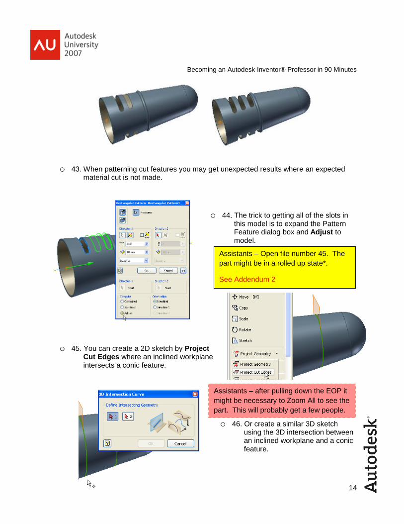
o 43. When patterning cut features you may get unexpected results where an expected material cut is not made.
o 44. The trick to getting all of the slots in this model is to expand the Pattern Feature dialog box and Adjust to model.
o 45. You can create a 2D sketch by Project Cut Edges where an inclined workplane intersects a conic feature.
o 46. Or create a similar 3D sketch using the 3D intersection between an inclined workplane and a conic feature.
Assistants – Open file number 45. The
part might be in a rolled up state*.
See Addendum 2
Assistants – after pulling down the EOP it
might be necessary to Zoom All to see the
part. This will probably get a few people.

15
Becoming an Autodesk Inventor® Professor in 90 Minutes
o 47. Now I Sweep two circles along the 2D and 3D intersection paths.
o 48. I have changed the 60 dimension to 50 and Updated the part. Notice that both sweep features updated properly in Inventor 2008. In previous releases the feature created with the Projected Cut Edges would not have updated properly.
o 49. You can change feature parameters simply by double clicking on the feature in the browser. The behavior has changed slightly in r2008. (In previous releases the sketch as well as the feature parameters would appear.)

16
Becoming an Autodesk Inventor® Professor in 90 Minutes
o 50. Sometimes when you open a part it is not oriented at the best viewing angle. Start the Rotate view command and hit the Spacebar and a common view glass box appears. Select the arrow for the view you want.
o 51. While the Common Views glass box is visible RMB and select Redefine Isometric.
o 52. You can rotate the view of the model 90° at a time by clicking on one of the edges of the glass box. The icon next to the cursor indicates which way it will rotate.
o 53. You can get back to free rotate by hitting the Spacebar again. You can center the Rotate view with a long click. Leave Rotate command by moving the cursor out of the arcball as shown and clicking in the graphics window or by hitting Esc.
Assistants – if we have Spaceballs I will also explain
how to navigate with them.

17
Becoming an Autodesk Inventor® Professor in 90 Minutes
o 54. The Rectangular Pattern tool can be used for more than just rectangular patterns.
o 55. The most common problem experienced by those who know this feature is somehow possible, but they can’t get it to work right is that their pattern is shifted and they forget that they can choose a new start point.
Assistants – open file #56.
Drag the EOP above Rectangular Pattern1 if I have it
already done. We will recreate the pattern adjusting
settings per steps #55-57.
18
Becoming an Autodesk Inventor® Professor in 90 Minutes
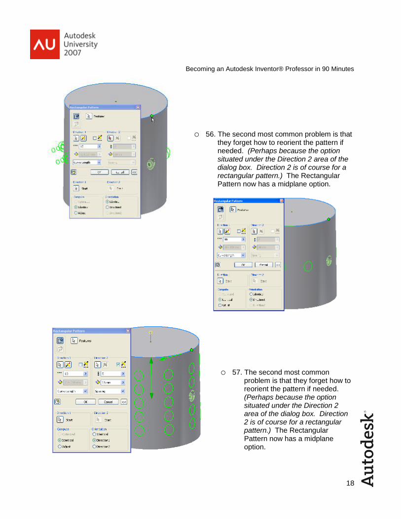
o 56. The second most common problem is that they forget how to reorient the pattern if needed. (Perhaps because the option situated under the Direction 2 area of the dialog box. Direction 2 is of course for a rectangular pattern.) The Rectangular Pattern now has a midplane option.
o 57. The second most common problem is that they forget how to reorient the pattern if needed. (Perhaps because the option situated under the Direction 2 area of the dialog box. Direction 2 is of course for a rectangular pattern.) The Rectangular Pattern now has a midplane option.

19
Becoming an Autodesk Inventor® Professor in 90 Minutes
o 58. The Coil command in Inventor 11 now allows creation of a surface. The edge of the coil surface can be used for a pattern curve.
o 59. Many people associate surface modeling with complex shapes, but they can also be used in the creation of fairly simple geometry. In this case a surface was used to create a sheet metal part that otherwise would have taken quite a bit more work to create.
o 60. Just as you can go back and forth between the Modeling and Sheet Metal environments and use Part Features to create sheet metal parts, you can also use Sheet Metal Features to create standard parts.
Assistants – no student action on #58-60.
Assistants – I made a change
after the files were submitted
and now these have the
wrong file numbers. #61
Assistants – I made a change
after the files were submitted
and now these have the
wrong file numbers. #62

20
Becoming an Autodesk Inventor® Professor in 90 Minutes
o 61. If you start working with surfaces be sure you understand when you have a surface and when you have a solid. (A surface feature will be translucent or a surface created
from a solid by the Delete Face tool will show at the top of the browser as a surface icon. If you use the Delete Face tool solid options will be disabled until you stitch your surfaces back to a solid.)
o 62. A hole in a surface model can be patched with the Boundary Patch tool.
o 63. Let’s put some of what we’ve learned to use. Create the sketch shown and Extrude 2 inches going down.
RGB=XYZ
Assistants – I made a change
after the files were submitted
and now these have the
wrong file numbers. #63
Assistants – no student action on #61-62.
Assistants – the majority of
the hands on class time will
be creating this Muffin Pan
from scratch.
Addendum 3
Assistants – make sure you know
how to Offset the .25 and how to
create the Ø.25 circle sketch.

21
Becoming an Autodesk Inventor® Professor in 90 Minutes
o 64. Create the sketched circle dimensioned as shown and Extrude Cut 1.375 with a Taper of -10°.
o 65. Add a .125 fillet at the top edge and a .0625 fillet at the bottom edge of the Extrude Cut.
Assistants – some are likely to have trouble with the
taper. Set on the More tab of the dialog box.
Assistants – I left out the creation of the Ø.25 circle sketch and a Sweep of the
circle. This will likely cause problems for some people as I demonstrate.

22
Becoming an Autodesk Inventor® Professor in 90 Minutes
o 66. Create a Rectangular Pattern of the Extrude and Fillet features..
o 67. Next we use Derived Components to create Core and Cavity tooling.
Assistants – 4ul x 2.375in and
3ul x 2.375in. It is not
necessary to enter the ul, but
some might make mistakes
here – like putting it in caps UL
or units.

23
Becoming an Autodesk Inventor® Professor in 90 Minutes
o 68. Perhaps one of the most underutilized feature options is the Intersect option available with many part feature tools. (Polygons must have a vertical or horizontal constraint to be fully constrained. Creating the tangent circle is an excellent use of the RMB Autoproject option.)
o 69. Check out the Thicken/Offset with the Cut option too.
o 70. Change the Thicken option to Intersection and we have our mating part.
Assistants – no student action on this page.
Assistants – part # 71 & 72
Assistants – part # 70

24
Becoming an Autodesk Inventor® Professor in 90 Minutes
o 71. And be sure to check out the new Face Fillet option.
o 72. Combine the Rectangle Pattern, Thicken with intersection options and some of the other tricks we have learned and you can create some fairly complex geometry. We might have to delve into Loft, Sculpt Trim/Extend Surface and some of the other advanced tools, but that is another class.
Assistants – no student action on this page.

25
Becoming an Autodesk Inventor® Professor in 90 Minutes
2D is Gravy
Traditional detailed 2D orthographic projections are almost an afterthought when created from
3D models.
o 73. If the base view comes in at an orientation that doesn’t fit well aesthetically it is easy to Rotate the initial Base View.
o 74. Here is a trick that will save you a lot of time in removing unnecessary hidden lines.
o 75. Use a window to select the unwanted hidden lines and RMB turn off the Visibility.
Assistants – open part #75.ipt
to use to create idw views.

26
Becoming an Autodesk Inventor® Professor in 90 Minutes
o 76. Simplify a section view by setting the Section Depth.
o 77. To speed up the view creation bitmaps are used by default for shaded views. For maximum image resolution on-screen go to Tools>Document Settings>Drawing tab and set Offline Only for shaded images.
If you have any questions be sure to catch me during breakfast, lunch or supper at AU or send me a email when you get back home.
Enjoy AU!
Assistants – create shaded isometric view and zoom in.

27
Addendum 1
If you are not familiar with changing project we will go to File>Projects…
And click Browse…

28
… and find the ipj file…
…and then make it the active Project.

29
Addendum 2
The part might open in a rolled up state with some or all features below the End of Part (EOP) marker. In any case I want the students to move the EOP to just below the Rectangular Pattern. Also note the location of the Part Feature Panel Bar.
I will ask everyone to set up their screen to look like mine. Some might accidently close the Panel Bar or Browser. You should do this yourself to practice getting it back. Under View>Toolbar menu or RMB (right mouse button) on any button along top of the screen.
We will then do #44 to adjust pattern to model.
The rest of the part is already done for the audience – I will do some explanation and then have them Double Click on the 50 dimension and change to 60 then Update.

30
Addendum 3
Start a new Inch part file and create the sketch.
Make sure they do not use construction linetype for the fillets.
Offset to the inside and add the .25 dimension.

31
Start a new sketch on the XZ Plane.
Project Geometry the line as a point on the sketch.
32
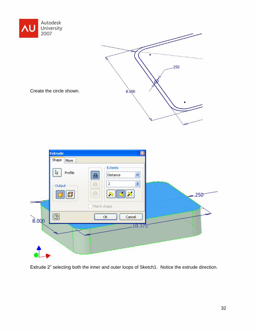
Create the circle shown.
Extrude 2” selecting both the inner and outer loops of Sketch1. Notice the extrude direction.
33
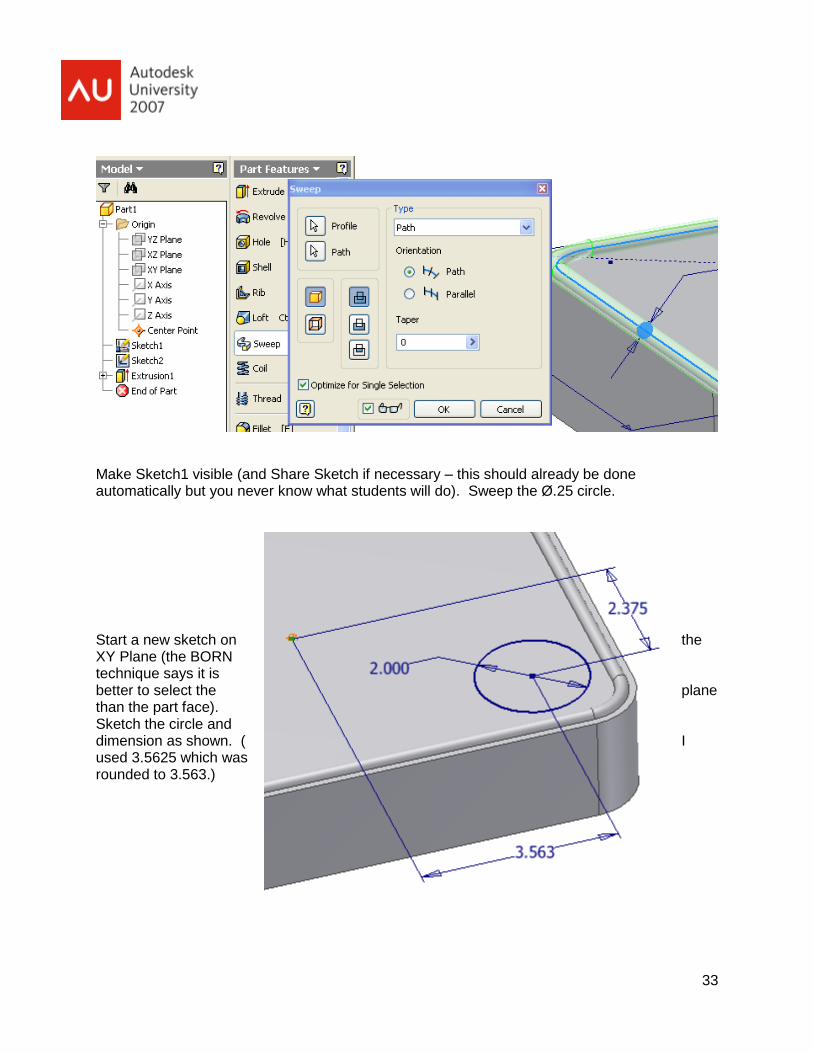
Make Sketch1 visible (and Share Sketch if necessary – this should already be done automatically but you never know what students will do). Sweep the Ø.25 circle.
Start a new sketch on the XY Plane (the BORN technique says it is better to select the plane than the part face). Sketch the circle and dimension as shown. ( I used 3.5625 which was rounded to 3.563.)

34
Extrude Cut…
…with Taper.

35
Fillet the cup edges.
The students might not know how to Click to add to add multiple fillet sizes to one feature or how to click on the edit pencil after changing the fillet radius to get back to the edge selection tool.
All kinds of things could go wrong here – I’ll go slowly.

36
Watch the Shell thickness.
Redefine Isometric.

37
Start a new Inch part file and exit sketch mode. Click Derived Component and select the Muffin Pan. Change to Body as Work Surface. A warning box will pop up – accept the warning.
Offset XY Plane 2” – some might not realize that you have to click the edge of a workplane to select the plane.

38
Save the file as Core.
Then File Save Copy As with the name Cavity.
Turn off the visibility of the Derived Work Body. Color as desired.

39
Double click on the offset Workplane1 in the browser and change the offset distance to negative 2. Click Update and Accept the error.
RMB on the Extrusion in the browser and select Recover.
Next, Next, Finish in the Design Doctor and select the Terminator selection tool in the Extrude dialog box and reselect the work surfaces.
Explain why this part isn’t the same as the Muffin Pan before we Shelled.
Then turn off the visibility of the derived work surfaces.