MA A-V UFP-V 0300rev03 7308503300 UK - Forbes Marshall ...€¦ · 4.2 mass calculation..... 54 4.3...
86
GR © KROHNE 11/2003 7.30850.33.00 Ultrasonic Flowmeters ALTOSONIC V Reference Guide Operating Manual Ultrasonic Flow Processor (UFP-V) Applicable for Software version 0300 Variable area flowmeters Vortex flowmeters Flow controllers Electromagnetic flowmeters Ultrasonic flowmeters Mass flowmeters Level measuring instruments Communications technology Engineering systems & solutions Switches, counters, displays and recorders Heat metering Pressure and temperature
-
Upload
hoanghuong -
Category
Documents
-
view
216 -
download
0
Transcript of MA A-V UFP-V 0300rev03 7308503300 UK - Forbes Marshall ...€¦ · 4.2 mass calculation..... 54 4.3...
GR
© KROHNE 11/2003 7.30850.33.00
Ultrasonic Flowmeters
ALTOSONIC VReference Guide
Operating ManualUltrasonic Flow Processor (UFP-V)
Applicable for Software version 0300
Variable area flowmeters
Vortex flowmeters
Flow controllers
Electromagnetic flowmeters
Ultrasonic flowmeters
Mass flowmeters
Level measuring instruments
Communications technology
Engineering systems & solutions
Switches, counters, displays and recorders
Heat metering
Pressure and temperature

ALTOSONIC V UFP-V Operating & Installation manual page 2 of 85
TABLE OF CONTENTS 1 SYSTEM CONFIGURATION........................................................................................................ 5
1.1 HARDWARE CONFIGURATION ............................................................................................................ 5 1.2 UFP-PROGRAM............................................................................................................................... 6
1.2.1 Initialisation data files....................................................................................................................... 6 1.2.2 On-line configurable data files ......................................................................................................... 6 1.2.3 Functionality..................................................................................................................................... 6
1.3 FEATURES....................................................................................................................................... 7 2 UFP-V START UP......................................................................................................................... 9
2.1 CALCULATION CRC CHECKSUM........................................................................................................ 9 2.2 READING INITIALISATION FILES ON INPUT RANGE .............................................................................. 11 2.3 START UP: SYSTEM SET-UP ERRORS ............................................................................................... 12 2.4 SYSTEM SET-UP WARNING.............................................................................................................. 13
3 RUNTIME USER WINDOWS...................................................................................................... 14 3.1 MAIN MENU: F1 MAIN WINDOW ...................................................................................................... 15 3.2 MAIN MENU: F2 ALARMS WINDOW................................................................................................... 16 3.3 MAIN MENU: F3 CORRECTIONS WINDOW ......................................................................................... 20 3.4 MAIN MENU: F4 STATISTICS WINDOW.............................................................................................. 22 3.5 MAIN MENU: F5 TREND-FLOW WINDOW ........................................................................................... 23 3.6 MAIN MENU: F6 PROFILE WINDOW.................................................................................................. 24 3.7 MAIN MENU: F7 BATCH WINDOW .................................................................................................... 25 3.8 MAIN MENU: F9 CONTROLS WINDOW .............................................................................................. 26
3.8.1 Controls menu: F2 API settings window ........................................................................................ 27 3.8.2 Controls menu: F3 External-flow meter window............................................................................. 29 3.8.3 Controls menu: F4 Manual override window.................................................................................. 30 3.8.4 Controls menu: F5 Density cell window ........................................................................................ 32 3.8.5 Controls menu: F6 Time window.................................................................................................... 33 3.8.6 Controls menu: F7 Reset Errors window........................................................................................ 34 3.8.7 Controls menu: F8 Reset Totalisers window.................................................................................. 35 3.8.8 Controls menu: F10 Quit measure mode window .......................................................................... 36
3.9 MAIN MENU: F10 SERVICE WINDOW................................................................................................ 37 3.9.1 Service menu: F2 Interrupts window.............................................................................................. 38 3.9.2 Service menu: F3 UFC errors window ........................................................................................... 39 3.9.3 Service menu: F4 UFC data .......................................................................................................... 40 3.9.4 Service menu: F5 Modbus errors window...................................................................................... 41 3.9.5 Service menu: F6 Modbus STATUS.............................................................................................. 42 3.9.6 Service menu: F7 Modbus data window ........................................................................................ 43 3.9.7 Service menu: F8 Parameter window ............................................................................................ 47 3.9.8 Service menu: F9 CRC-data window ............................................................................................. 48 3.9.9 Service menu: F10 IO window ....................................................................................................... 49
4 CALCULATION OF STANDARD VOLUME AND MASS.......................................................... 50 4.1 VOLUMETRIC STANDARD ................................................................................................................ 50
4.1.1 Calculation of correction temperature dependency Ctl ................................................................... 50 4.1.2 Calculation of correction pressure dependency Cpl........................................................................ 51 4.1.3 Operating with the standard density............................................................................................... 52 4.1.4 Operating with the measured density............................................................................................. 53
4.2 MASS CALCULATION....................................................................................................................... 54 4.3 SOLARTRON METER DENSITY IS CALCULATED AS FOLLOWS:.............................................................. 54 4.4 SARASOTA METER DENSITY IS CALCULATED AS FOLLOWS: ................................................................ 55
5 BATCH MODE............................................................................................................................ 56 5.1 HARDWARE SET-UP ....................................................................................................................... 56 5.2 LAYOUT OF THE TICKET .................................................................................................................. 56 5.3 PARAMETER MAPPING ADDRESSES ................................................................................................. 58
5.3.1 Ticket number: ............................................................................................................................... 58 5.3.2 Times:............................................................................................................................................ 58 5.3.3 Operate names (optional at batch set-up):..................................................................................... 58

ALTOSONIC V Operating & Installation Manual page 3 of 85
5.3.4 Resetable Totalisers (at start and stop time): ................................................................................ 58 5.3.5 Non Resetable Totalisers (at start and stop time):......................................................................... 58 5.3.6 Batch Flow weighted averages: ..................................................................................................... 58 5.3.7 Batch alarms in seconds:............................................................................................................... 59 5.3.8 Configuration API etc..................................................................................................................... 59 5.3.9 Security:......................................................................................................................................... 59 5.3.10 Special characters for printer control: ............................................................................................ 59
5.4 INITIAL BATCH SET-UP .................................................................................................................... 60 5.5 BATCH STATUS .............................................................................................................................. 61 5.6 PRINTER STATUS ........................................................................................................................... 61 5.7 PRINTER TASK STATUS................................................................................................................... 61 5.8 BATCH SET-UP............................................................................................................................... 62
5.8.1 API set-up...................................................................................................................................... 62 5.8.2 Batch text set-up............................................................................................................................ 63 5.8.3 Ready to start batch after set-up is complete................................................................................. 63
5.9 BATCH START ................................................................................................................................ 64 5.10 DURING BATCH.......................................................................................................................... 65
5.10.1 Reading / Printing previous batch ticket......................................................................................... 65 5.11 BATCH STOP ............................................................................................................................. 67
5.11.1 Possible errors that cause an Invalid Batch ticket.......................................................................... 68 5.11.2 Measurement alarms batch validation ........................................................................................... 69
5.12 CONTINUOUS PIPELINE MEASUREMENT TICKETS ......................................................................... 70 5.13 EXAMPLE OF TICKET TO OUTPUT:................................................................................................ 71
6 DATA ACQUISITION.................................................................................................................. 72 6.1 DATA INPUT RS485 CARD.............................................................................................................. 72 6.2 DIGITAL INPUTS MP103 CARD ........................................................................................................ 73 6.3 FREQUENCY INPUTS MP103 CARD ................................................................................................. 74 6.4 ANALOG INPUTS AD CARD.............................................................................................................. 75
7 OUTPUT...................................................................................................................................... 76 7.1 FREQUENCY OUTPUT MP103 CARD ................................................................................................ 76 7.2 ANALOG OUTPUT MP103 CARD ...................................................................................................... 77 7.3 RELAY OUTPUT MP103 CARD......................................................................................................... 77 7.4 ANALOG OUTPUTS AD CARD.......................................................................................................... 78 7.5 DIGITAL OUTPUTS AD CARD ........................................................................................................... 79 7.6 MODBUS COMMUNICATION ............................................................................................................. 80
8 HARDWARE CONFIGURATION ............................................................................................... 81 8.1 MP103 CARD ................................................................................................................................ 81
8.1.1 MP103 revision: 3.31300.02 .......................................................................................................... 81 8.1.2 MP103 revision: 3.39993.01 .......................................................................................................... 81 8.1.3 The signals on the D connectors of the MP103 cards.................................................................... 82
8.2 RS485/422 CARD ......................................................................................................................... 83 8.2.1 RS485/422 card: AX4285A............................................................................................................ 83 8.2.2 RS485/422 card: PCL-745 S ......................................................................................................... 84

ALTOSONIC V Operating & Installation Manual page 4 of 85
INTRODUCTION This manual describes the operation of the ALTOSONIC-V ultrasonic flow-meter system and the handling of the data-files. Also, in this manual you will find a description of the computer that is used, its data-acquisition and control cards, the software, possible errors and recommendations. Note that in this manual standard and optional specifications of the ALTOSONIC V are described. Nothing from this document may be copied or reproduced without the written permission of KROHNE Altometer.

ALTOSONIC V Operating & Installation Manual page 5 of 85
1 SYSTEM CONFIGURATION
1.1 Hardware configuration The flowchart below includes all hardware specifications of the ALTOSONIC V regarding the flow measurement.
Ultrasonic Flow Sensor
(primary)
5 Ultrasonic Flow
Converters Temperature Proces
Temperature Body
Temperature Proving (Ext flow)
Temperature densitometer
Pressure Proces
Density standard
Density densitometer
Viscosity External
Pressure Proving
(Ext flow)
Pressure Densitometer
Secundairy Input signals
External Flow (Puls rate)
Configuration Data files
UFS-V UFC-V UFP-V
Online files
Online status files
RS485/422 card 2 com ports
program: measure
calibrate AD /FR
MP103 card 4 dig inputs
4 dig outputs 1 frequency outp 1 current output 2 frequency inp 1 pulscounter
Processor Card
AD Card (16 analog inputs 2 analog outputs
All secundairy input signals can be read as Modbus inputs from a host (except External flow puls rate)
Density densitometer signal can be connected from Solartron/Sarasota Frequency signals. All Densities can be configured as normal frequency spans
Serial Batch Printer according DIN66258
Modbus Master/Slave to host system Rs232/422/485
2 Current outputs*****
2 frequency outputs***** 1current output*****
4 digital outputs
OUTPUTS
***** Possible parameters on outputs:Flow proces Flow standard Flow mass Density Proces Density standard Velocity of sound Volume correction factor Viscosity Temperature Proces Pressure Proces
From this point on, in this manual the following abbreviations will be used: UFS-V : Ultrasonic Flow Sensor (primary flowmeter body) UFC-V : Ultrasonic Flow Converter (5 converters) UFP-V : Ultrasonic Flow Processor UFP-Program : Software program running on the UFP for measuring the flow.

ALTOSONIC V Operating & Installation Manual page 6 of 85
1.2 UFP-Program The operating system is DOS 6.22 for its proven reliability using real time data Processing. The UFP-Program is controlled by initialisation data files and on-line configurable data files.
1.2.1 Initialisation data files
These files can be accessed by a DOS-editor when the UFP-Program is not running. The Initialisation data files are divided into 3 groups: UFS files : Calibration data regarding the Ultrasonic Flow Sensor (primary) UFP files : Calibration and configuration data on the hardware set up within the UFP (cards etc) DAT files : Client configuration data regarding the set up of communication and signal IO.
1.2.2 On-line configurable data files
These files are binary and only accessible when the UFP-program is on-line. API.bin : API settings on standard volume correction DENSITOx.bin : 4 files for calibration data on densitometer cells Solartron 1 & 2, Sarasota 1 & 2 EXTERN.bin : External flow meter settings (if connected). OVERRIDE.bin : Override value settings
1.2.3 Functionality
The functionality can be divided into primary and secondary functions Primary functions: • Monitor data- and system integrity • Data acquisition: data of five converters and optional data such as temperatures, pressures,
densities, control bits, etc. • Check the measured data from the five converters and handle errors, if necessary. • Calculate the Process volumetric flow in the primary head from the measured data. • Calculate the standard volumetric flow (e.g. 15 °C, 1.01325 bar), if installed. Standard temperature
can be set in the range 0-30°C. • Totalise Process and standard flow as measured volumes • Flow weighted averages on batching (temperature, pressure, density etc). • Resetable and non resetable totalisers • Prove external flow meter if installed. • Output of calculated data and errors through: frequency output, analog outputs, digital outputs and
Modbus communication. • Possibility to override the input values (Temperatures, Pressures, Densities etc on line). Override
is signalled as an alarm. • Printing of tickets for batch functions such as Off Loading and Continuous Pipeline Measurement Secondary functions: • Statistics • Back-up history such as totalisers, averages and alarms. • Various screen functions for real-time monitoring.

ALTOSONIC V Operating & Installation Manual page 7 of 85
1.3 Features Data measured RS485 UFC-V ↔ UFP-V (data communication connection between UFC-V and UFP-V):
Flow velocity -five times (as a percentage) Transit time -five times
Status UFC-V -out of range, path failure, communication failure Analog in Temperature : body, Process, densitometer*, external flow meter*
Pressure : Process*, densitometer*, external flow meter* Density : Process*, standard*, densitometer* Viscosity : external*
External flow meter : Pulse counter* Digital in Start /Stop signals calibration (KROHNE used), or switch Densitometer calibration data Reset volumes and errors Reset errors Data Processed for output to user Flow : Process flow, standard flow*, mass flow* Sound velocity : five channel values, mean value Resetable Totals : Process volume, standard volume*, mass*. All forward, reverse, total. Non resetable Totals : Process volume, standard volume*, mass*. All forward, reverse, total. API Density : Process, standard*, densitometer* Analog in Temperature : body, Process*, densitometer*, external flow meter* Analog in Pressure : Process*, densitometer*, external flow meter* Analog in Density : densitometer*, standard* Analog in Viscosity : external* Flow weight averages : Temperature (body, Process*, Proving external*, standard*, densitometer*)
Pressure (Process*, Proving external*, densitometer*) Density (Process*, standard*, Proving external*, densitometer*) Corrections (Ctl & Cpl values*) Viscosity (external dynamic*) [2 sets averages (= made in two time intervals*)]
Batch ticket print : All output values can be printed by freely definable layout configuration Data integrity Alarms on flow data Alarms on system Alarms on Low/High Analog inputs* Data corrections under normal conditions Reynolds correction Temperature expansion correction Standard volume correction according to API 2540* standard Data corrections under alarm conditions Real time profile correction on channel failure On-line override values on analog inputs* Filtering of measured data* Service values on Modbus (measured by UFP but not used for calculation directly) All temperatures, pressures, densities and Viscosity * = Optional

ALTOSONIC V Operating & Installation Manual page 8 of 85
Secondary input Function Temperature body For correction of the expansion of the UFS, resulting in a correction
factor Kb on the measured flow Temperature Process*
For standard volume correction Resulting in a correction factor Ctl 15 to Process on the measured flow
Temperature Process** For correction on standard calibration volume (Factory use only). Function is only applicable when the calibration is not only monitored by the calibration facility but also, with a digital start/stop signal, by the UFP. The standard calibration volume is the volume measured at a standard temperature
Temperature densitometer* For standard volume correction Resulting in a correction factor Ctl 15 to densito on the measured flow
Temperature external Flow meter*
For standard volume correction Resulting in a correction factor Ctl 15 to proving on the external flow
Pressure Process* For standard volume correction Resulting in a correction factor Cpl Process on the measured flow
Pressure densitometer* For standard volume correction Resulting in a correction factor Cpl densito on the measured flow
Pressure external Flow meter*
For standard volume correction Resulting in a correction factor Cpl proving on the external flow
Densitometer density* The density measured by the densito meter Density standard* The density standard with at predefined standard temperature External viscosity* External kinematic viscosity, for display and calibration use
* = Optional **= KROHNE Altometer calibration use only

ALTOSONIC V Operating & Installation Manual page 9 of 85
2 UFP-V START UP When the UFP is powered the UFP-Program starts automatically. To prevent unattended changes to the initialisation files the data is protected at start-up by: • Calculation CRC checksum • Check data from files on input range limits • Password
2.1 Calculation CRC checksum Each file has a CRC checksum. When anything changes in the file, the CRC-checksum will also change. At the start-up of the UFP-V the CRC checksums are calculated and checked: Start-up: If the checksum of a file is not identical to the one saved at the previous start-up in the CRC_NORM file, the program switches to fail mode.
CRC checksum: All data files have a CRC checksum CRC checksums are saved in file: CRC_NORM.ufs CRC_NORM.ufp CRC_NORM.dat Back-up of all data files in: CRC_FILE.ufs CRC_FILE.ufp CRC_FILE.dat CRC checksums and length of each file is saved in: CRC_BACK.ufs CRC_BACK.ufp CRC_BACK.dat (CRC checksums of these files are within the file)
Fail mode: Possible cause: Change of data in file Only breakable by pin code: 1357

ALTOSONIC V Operating & Installation Manual page 10 of 85
CRC checksum error If the fail mode is caused by a CRC-checksum error, there are three options: 1. Calculate a new CRC-checksum. The calculation is protected by password. 2. Load the backup file 3. Escape
Make new CRC checksum To make a new CRC-checksum and to start the measure mode follow these steps: 1. MEAS [enter] (Batch file to start the measure mode) 2. 1357 (Pin code to stop the fail mode) 3. 1 (Choice to make a new CRC-checksum) 4. “Your password” (Pin code to make the new CRC checksum) 5. MEAS [enter] (Batch file to start the measure mode)
Note that the password can only be changed when the UFP-Program is running. To change it: - Go to the Main Window - Type code : PSSWRD - Follow the directions in the window - After the password is changed, the program automatically shuts down and a new CRC-checksum
must be created. Start the UFP-Program and make the new CRC-checksum by using your new password.
Causes: 1 Change made in data file 2 sudden checksum error (not likely to happen) Possible actions: 1 new crc-checksum. 2 Load backup file:
If crc checksum of backup files also fail, backup file not loaded. Check parameter file
3. Escape
Making the new crc file: 1 Type the password On delivery the password is 7531 2 Enter When more than 30 characters are typed during input of the password the UFP-Program terminates and the UFP-Program must be restarted to make the new crc-file

ALTOSONIC V Operating & Installation Manual page 11 of 85
2.2 Reading initialisation files on input range Each parameter is checked for its input range.
1. If a parameter is out of range, the software switches to fail-mode.
(Only breakable by pincode 1357) 2. In fail mode a system set-up Error Code is given.
The parameter and its input range are printed on screen. If the Modbus communication is active the set-up Error Code is also available on this output.
3. If there are no problems at start-up, the software checks whether the CRC-checked data files
correspond with the backup files CRC_FILE.UFS, CRC_FILE.UFP and CRC_FILE.DAT. These backup file also have CRC-checksums. Only when a group (UFS, UFP or DAT) data files do not correspond or the backup checksum gives an error, a new backup file and checksums are made of that group.

ALTOSONIC V Operating & Installation Manual page 12 of 85
2.3 Start up: system set-up errors The system SET-UP ERRORS are caused by an improper initialisation such as data–change etc. If the UFP-V identifies a system set-up error, it switches to fail-mode. The fail-mode shows the found error and the elapsed Process error time. The mode can only be stopped by pin code 1357. Identified set-up errors are: Error No.
Function Problem How to solve
1 CRC Error opening: file(filename) to check on CRC Try to load backup (CRC-function) 2 CRC Error closing: file(filename) to check on CRC Try to load backup (CRC-function) 3 CRC Error opening: CRC-code file(filename) Try to load backup (CRC-function) 4 CRC Error closing: CRC-code file(filename) Try to load backup (CRC-function) 5 CRC Error length: CRC-code file(filename) Make new CRC checksum 6 Common, opening file Error in path: file(filename) not found Try to load back-up (CRC-function) 7 Not in use Not in use in this version 8 Common, read in table File(filename), maximum rows exceeded Put in less data points 9 Common, closing file Error read in file(filename) Try to load backup (CRC-function) 10 Common, closing file
Error write in file(filename) Try to load backup (CRC-function)
11 Read in profiles Error in file(filename): a parameter <|0.01| Try to load backup (CRC-function) 12 Not in use Not in use in this version 13 Check on serial
numbers Serial numbers in parameter files do not correspond
Check the serial number in files
14 Initialising Graph driver Graphics error Is egavga.bgi file in directory ASV0300? 15 File location Error in finding disk Check the file locations in HSET0300.ufp16 Frequency set-up Error in set-up frequency output Follow instructions on screen 17 Common, read in
parameter Error in a parameter file, bad up-dating, make sure that ‘#’ is first
Check your last updated file or load backup (CRC function)
18 Common, read in parameter
Error in a parameter file, number too large (more then x characters)
Check your last updated file or load backup (CRC function)
19 Factory use only 20 Factory use only 21 Not in use 22 Check location
executable Error in LOCATION_EXE, Process location is disk x
Change LOCATION_EXE in HSET0300.ufp
23 Not in use 24 Check parameters on
range Out of range in file(filename), parameter(name)=x, Must be in range x1…x2
Follow the instructions on screen
25 CRC-checksum outcome
CRC checksum not correct! Make a new checksum or if not certain about the data, load the backup (CRC-function)
26 Not in use 27 CRC-checksum CRC backup-files checksum not correct Fill in the correct data in actual files
Backup 28 Batch status files When the batch mode is enabled and the batch
status files are not found at start-up. After breaking the fail mode follow the instruction on screen to insert your last ticket number
29 Initialisation Printer When the batch mode is enabled, the printer software is initialised. On error of initialisation
Check the COMS0300.dat file for errors in Printer set-up
30 Password If for any reason the password is lost Try to load backup (CRC-function)

ALTOSONIC V Operating & Installation Manual page 13 of 85
The errors, which may occur during the initialisation of the Modbus Driver and the initialisation of the driver for the communication with the ultrasonic converters, are listed below. See for the communication system set-up errors also the ALTOSONIC V ModBus Manual. Returned error numbers: Error No.
Problem How to solve
1001 Modbus driver: Requested interrupt not supported Make sure MODBUS_UART_INTERRUPT is within the limits (3 or 4) 1002 Modbus driver: Requested baud rate is not
supported Make sure MODBUS_UART_BAUDRATE is within the limits (1200,2400,4800,9600,19200)
1003 Modbus driver: Parity setting error Make sure MODBUS_UART_PARITY is within the limits (0,1,2) 1004 Modbus driver: Stop bit error Make sure MODBUS_UART_N_STOPBITS is within the limits (1,2) 1005 Modbus driver: RTS_MODE not supported Make sure MODBUS_UART_RTS_MODE is within the limits (0 or 1 ) 1006 Modbus driver: Number of bits not supported Make sure MODBUS_UART_N_DATABITS is within the limits (7 or 8) 1007 UFC driver: UART_init parameters error Make sure Setting for the UFC communication are correct 1008 Modbus driver: too many poll blocks installed Make sure NUMBER_OF_POLLBLOCKS_TO_USE is not larger than
20 1009 Modbus driver: function 6 only supports integer
types in modicon compatible mode When using the Modbus master mode in modicon compatible mode, function 6 only support integer types. When Other types (float, double…) are necessary use function 16.
1010 Modbus driver: Slave ID not in range of 0…247 The Slave ID in a poll block request must be between 1 and 247 or in case of a broadcast 0.
1011 Modbus driver: Broadcast not allowed for this function (pollblock x)
Use a valid Slave ID to access only 1 slave.
1012 Modbus driver: Function 5 and 6 can only handle 1 point (poll block x)
When using function 5 or 6, make use the number of points is 1, these functions can handle only one point.
1013 Modbus driver: Minimum number of points to request is 1 (poll block x).
Make sure that at least 1 point is used for this action.
1014 Modbus driver: data type not allowed (poll block x)
The data type of the poll block is not the same as the data type in the Modbus mapping
1015 Modbus driver: unsupported data address, or request number of points out of range
The requested points must be in the available Modbus mapping.
1016 Modbus driver: Data type / function mismatch Make sure the Modbus function and the allowed data type do match 1017 Modbus driver: Too many points requested Make sure the Modbus message length is not exceeded, request
fewer points. 1018 General: unable to open the communication set-
up file Make sure the coms0300.dat file exists in this directory
1019 General: unable to close the communication set-up file
Make sure the Drive is still powered.
1020 General: error reading communication set-up file in parameter x
A parameter was expected but could not be read, make sure all the variables start with a #
1021 General: error reading communication set-up file in parameter x, parameter out of range
A parameter was read, but not within the expected limits.
1022 General: PC timer initialisation failed. Try to restart the flow computer (cold start) else contact KROHNE Altometer
2.4 System set-up warning The system set-up warnings (SSW) are caused by: • Insufficient statistical data during set-up (file REAL.BIN was not found)
Default data is used until sufficient statistical information is recorded (under normal conditions within 3 minutes under normal flowing conditions). In this case the warning is self-resolving.
• Improper initialisation of the Modbus driver Modbus will not be accessible. In this case the warning remains active.

ALTOSONIC V Operating & Installation Manual page 14 of 85
3 RUNTIME USER WINDOWS In measure mode the screen is always divided into two parts. • The Status Window at the bottom of the screen • The Runtime User Window which is above the Status Window Function keys control the Runtime User Windows. At the bottom of the Status Window the possible functions are showed for the particular Runtime User Window. The status window: It shows: • Serial # : Serial number assigned by KROHNE Altometer • Tag # : Tag number that can be defined by the user • Version : Software version number • Data : CRC-checksum of the 3 data sets (UFS, UFP, and DAT).
This can be a first check for the data integrity (every change in a data set changes the checksum of that data set). Details can be found under F10 Service, F9 CRC-Data
• Window : The name of the Runtime window showing above • Warnings : Number of actual warnings, details can be found in the Alarms window (F2) • Alarms : Number of actual alarms, details can be found in the Alarms window (F2) The following items are only shown if the batch mode is enabled in the initialisation file CLNT0300.dat • Batch : Batch status • Printer : Printer status • Task : Print task For more details on Batch mode see chapter 5.

ALTOSONIC V Operating & Installation Manual page 15 of 85
3.1 Main menu: F1 Main window The Main window is the default start-up window. This window shows an overview of the system and can always be accessed by function key F1. Explanation of the Main window layout: UFC-DATA shows: • Raw data of the 5 channels regarding flow % and Velocity Of Sound (V.O.S.) • A red marker (▪) per channel shows an active channel failure, a green marker (▪) shows a
previously occurred channel failure CONDITIONS show: • Temperatures, pressures and densities measured or calculated for the conditions of Process,
Standard, Densitometer and the optional external flow meter. • A red marker (X) in front of a parameter shows an alarm for out of range or manual on-line
override, a green marker (X) shows a previously occurred alarm UFP-CALC shows: • Flow rates at Process conditions, Standard conditions and Mass EXTERNAL FLOW METER shows (if enabled) • Flow rate at measurement conditions(external conditions) • Standard Volume Totaliser (summation of forward and reverse) • Difference between External and ALTOSONIC-V volume. RESETABLE TOTALISERS shows: • The forward, reverse and summation of the Totaliser values at Process conditions, Standard
conditions and Mass. • The resetable totalisers can be reset in the Control menu: F8 RES-TOT. It is also possible to reset
the totalisers by digital input signal or Modbus boolean. NON RESETABLE TOTALISERS shows: • The forward, reverse and summation of the Totaliser values at Process conditions, Standard
conditions and Mass.
Optional: -external flow meter -external viscosity
The status window is showed in every window of the measure mode
Possible options using function key control
MAIN window

ALTOSONIC V Operating & Installation Manual page 16 of 85
3.2 Main menu: F2 Alarms window The Alarm window shows all alarms and warnings as occurred [seconds]. Explanation of the Alarms window layout: CHANNEL ERROR shows: There are 5 types of errors 1. OOR, Out Of Range, flow data from the UFC is out of the limits – 125...+125% flow rate.
Possible causes are: • Flow out of range • Empty pipe • Problem with sensor • Problem with converter Common check is: • Value of the Process flowrate
2. PATH, Path failure. The transmitted signal from one sensor is not correctly received by the other sensor. Possible causes are: • Empty pipe • Particles or solids in the fluid • Cavitation due to low Process pressure resulting in gas bubbles • Problem with converter Common checks are: • Process pressure • Value of the Process flow rate
3. DEV.C, Deviation in sound velocity The UFP calculates the mean sound velocity out of the three most nearby channel values (5 times) and then checks all channels on their deviation to this mean value Deviation limit is set default to –0.5…+0.5 % of mean V.O.S. Possible causes are: • Local density variations due to sludge, mixtures or temperature variations • Empty pipe • Problem with converter • Problem with sensor Common checks are: • Flow and sound velocity per channel
ALTOSONIC V Operating & Installation Manual page 17 of 85
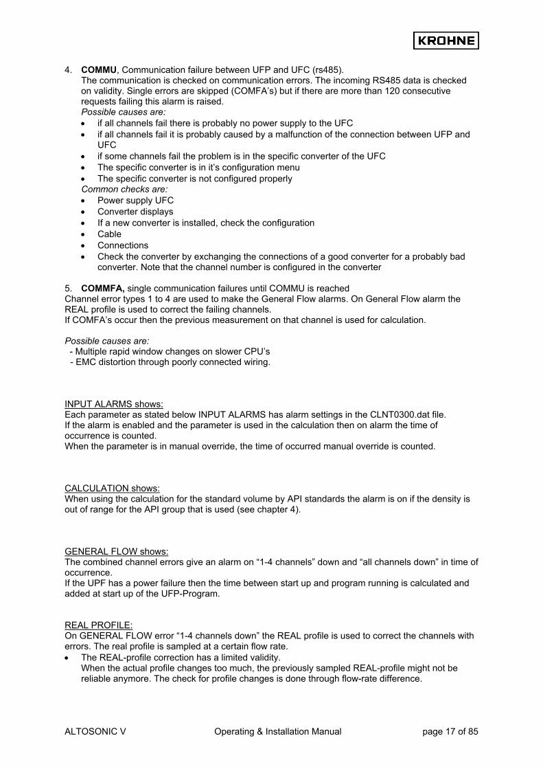
4. COMMU, Communication failure between UFP and UFC (rs485). The communication is checked on communication errors. The incoming RS485 data is checked on validity. Single errors are skipped (COMFA’s) but if there are more than 120 consecutive requests failing this alarm is raised. Possible causes are: • if all channels fail there is probably no power supply to the UFC • if all channels fail it is probably caused by a malfunction of the connection between UFP and
UFC • if some channels fail the problem is in the specific converter of the UFC • The specific converter is in it’s configuration menu • The specific converter is not configured properly Common checks are: • Power supply UFC • Converter displays • If a new converter is installed, check the configuration • Cable • Connections • Check the converter by exchanging the connections of a good converter for a probably bad
converter. Note that the channel number is configured in the converter
5. COMMFA, single communication failures until COMMU is reached Channel error types 1 to 4 are used to make the General Flow alarms. On General Flow alarm the REAL profile is used to correct the failing channels. If COMFA’s occur then the previous measurement on that channel is used for calculation. Possible causes are: - Multiple rapid window changes on slower CPU’s
- EMC distortion through poorly connected wiring. INPUT ALARMS shows: Each parameter as stated below INPUT ALARMS has alarm settings in the CLNT0300.dat file. If the alarm is enabled and the parameter is used in the calculation then on alarm the time of occurrence is counted. When the parameter is in manual override, the time of occurred manual override is counted. CALCULATION shows: When using the calculation for the standard volume by API standards the alarm is on if the density is out of range for the API group that is used (see chapter 4). GENERAL FLOW shows: The combined channel errors give an alarm on “1-4 channels” down and “all channels down” in time of occurrence. If the UPF has a power failure then the time between start up and program running is calculated and added at start up of the UFP-Program. REAL PROFILE: On GENERAL FLOW error “1-4 channels down” the REAL profile is used to correct the channels with errors. The real profile is sampled at a certain flow rate. • The REAL-profile correction has a limited validity.
When the actual profile changes too much, the previously sampled REAL-profile might not be reliable anymore. The check for profile changes is done through flow-rate difference.

ALTOSONIC V Operating & Installation Manual page 18 of 85
• When the sampled REAL-profile flow rate differs too much from the actual flow-rate during REAL-profile correction this is shown as a warning.
CORRECTION WARNINGS shows: • If there is too much flow variation for corrections, the corrections go on hold. When the corrections
are on hold the real time profile is used as a standard for correcting the flow. • If there are too much flow variations or channels failing, the sampling of the REAL profile goes on
hold. On release the sampling is started at maximum time for sampling a profile. SYSTEM ERRORS shows: The status of the system is divided into: • System Runtime Warnings. These are caused by system failures. These failures will not influence
the flow measurement. • System Runtime Alarms. These are caused by system failures. These failures might influence the
flow measurement. Identified System Runtime Errors are numbered 1 to 60 are:
Identified System Runtime Errors are numbered 1 to 60, A = alarm, W = warning: Error no. In function Problem Consequence A : 1 Get RS485 data from
converters Overrun, missed data Missed data, message
A : 2 Self test Error in memory self-test Non-reliable memory A : 3 Batch start / stop Error during saving files of start or stop File lost but ticket is made A : 4 Profile correction (REAL) Error in state_correction Attempt divide to by zero W: 5 Read Backup all files Error in reading backup file Possible loss of backup file W: 6 Switching disk Error in finding a drive Message W: 7 System time A notice that the system time was adjusted
manually or by Modbus. No consequence for totalisers or Process time, only on ticket time
W: 8 End of a calibration Error write in calibration report File lost, message A: 9 Batch status backup Status file corrupt Possible loss of batch status W: 10 Override values files Error in opening/closing override value file Override values not stored but
still in use A: 11 Batch totaliser backup Totaliser backup-file corrupt File lost , message A: 12 Batch average backup Average backup-file corrupt File lost, message A: 13 Batch ticket create Error in creating batch ticket file Ticket itself is made for printing
but lost during saving W: 14 Opening file (for update) Error in opening REAL file File lost, message W: 15 Closing file (for update) Error in closing REAL file File lost, message W: 16 API settings Error in file, defaults are loaded and saved Old settings lost W: 17 Batch 2 A alarm on batch 2 file (Batch 2 is only
used through Modbus with a Scada system) File lost, message
W: 18 Check free disk-space Error dos_getdiskfree() call Time-out function 30 s W: 19 Check free disk-space Low on disk-space Time-out function 30 s W: 20 Ad card overrun The requested AD card is not noticed Solve the problem W: 21 Opening file (for update) Error opening API table file File lost, message W: 22 Value check 1 or more API values defaulted Check the installed parameters W: 23 Opening file (for update) Error opening external flow meter file File lost, message W: 24 Value check Default external flow meter K-factor Check the installed K-factor W: 25 Counter input Unable to read Counter value Read on next entry A : 26 Calibration MP103 card MPCA File corrupt Install backup A : 27 Calibration AD card File corrupt Install backup A : 28 Calibration data Densito
Cells File corrupt Automatic install of default values
Set the correct values on-line A : 29 Batch ticket currently
saved A Requested batch ticket not available for printing
A ticket by that name was not saved or had a previous save error
A : 30 Batch ticket CRC error in a Batch ticket A ticket was not saved correctly or was changed manually
W: 31 Read batch ticket previously saved
A Requested batch ticket not available for printing
A ticket by that name was not saved or had a previous save error
W : 32 Batch ticket close file Error in closing a ticket file Ticket file not closed , probably because it could not be opened
ALTOSONIC V Operating & Installation Manual page 19 of 85
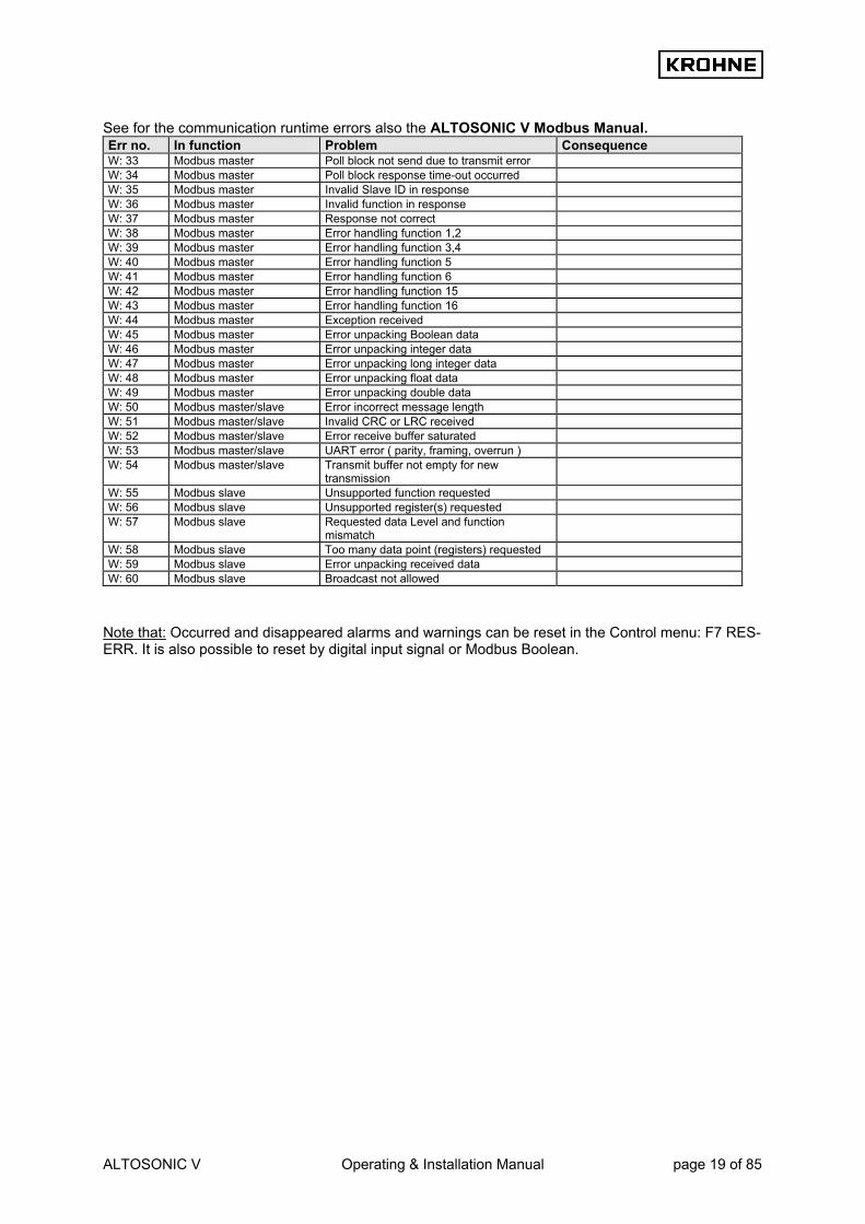
See for the communication runtime errors also the ALTOSONIC V Modbus Manual. Err no. In function Problem Consequence W: 33 Modbus master Poll block not send due to transmit error W: 34 Modbus master Poll block response time-out occurred W: 35 Modbus master Invalid Slave ID in response W: 36 Modbus master Invalid function in response W: 37 Modbus master Response not correct W: 38 Modbus master Error handling function 1,2 W: 39 Modbus master Error handling function 3,4 W: 40 Modbus master Error handling function 5 W: 41 Modbus master Error handling function 6 W: 42 Modbus master Error handling function 15 W: 43 Modbus master Error handling function 16 W: 44 Modbus master Exception received W: 45 Modbus master Error unpacking Boolean data W: 46 Modbus master Error unpacking integer data W: 47 Modbus master Error unpacking long integer data W: 48 Modbus master Error unpacking float data W: 49 Modbus master Error unpacking double data W: 50 Modbus master/slave Error incorrect message length W: 51 Modbus master/slave Invalid CRC or LRC received W: 52 Modbus master/slave Error receive buffer saturated W: 53 Modbus master/slave UART error ( parity, framing, overrun ) W: 54 Modbus master/slave Transmit buffer not empty for new
transmission
W: 55 Modbus slave Unsupported function requested W: 56 Modbus slave Unsupported register(s) requested W: 57 Modbus slave Requested data Level and function
mismatch
W: 58 Modbus slave Too many data point (registers) requested W: 59 Modbus slave Error unpacking received data W: 60 Modbus slave Broadcast not allowed
Note that: Occurred and disappeared alarms and warnings can be reset in the Control menu: F7 RES-ERR. It is also possible to reset by digital input signal or Modbus Boolean.

ALTOSONIC V Operating & Installation Manual page 20 of 85
3.3 Main menu: F3 Corrections window The Corrections window monitors the corrections. Explanation of the Corrections window layout: REAL-P shows: • The previously sampled profile. • The remaining update time to make the new REAL profile. • The sampling goes on hold if:
- Channel errors occur - Less than 5% flow rate This will show in yellow colour as HOLD.
• The validity range in flow rate percentage of the sampled REAL profile. Out of this range an alarm condition is activated
CORRECTION REYNOLDS: There are two ways of making the Reynolds correction. 1. The cinematic viscosity is measured and the Reynolds number is calculated from F(Viscosity,
Diameter, Velocity). By a calibrated Reynolds table the correction factor Kr is found 2. Through the calibrated Reynolds table the correction Kr is found In the picture method 1 is in grey meaning this method is not used to make the Reynolds correction factor Kr. In the picture method 2 is in light-blue meaning this method is used to make the Reynolds correction factor Kr. The green arrow at the Kr location shows that this Kr factor is used in the flow calculation. No arrow means: Not used. When the correction is on hold due to flow variations this is shown in yellow as HOLD at the Kr location. During the hold period the corrections are done with the REAL-profile as a reference. SWIRL shows: As a last help on build-in-site a swirl correction can be made in case of swirl, but strongly recommended is to avoid swirls by using flow-straighteners that are calibrated together with the ALTOSONIC-V flow meter. The swirl number (Swnr.) is an indication for the found swirl. A normal value is 0…0.250. A value higher than this indicates a swirl that can influence the flow measurement.

ALTOSONIC V Operating & Installation Manual page 21 of 85
Because the swirl also influences the profile this also influences the Reynolds correction. The deviation for the ratio number A and B are given. These are used to make the Swirl calibration table. By default the swirl correction factor is not used. Only if there is physically no way to correct a swirl it is used to make a more reasonable flow value but this value is not guaranteed to be within specs of the ALTOSONIC-V because of possible uncalibrated swirl intensities and viscosities. • The green arrow at the Ks location shows that the factor is used in the flow calculation. No arrow
means: Not used. • If the correction is on hold due to flow variations, this is shown in yellow as HOLD at the Ks
location. During the hold period the corrections are done with the REAL-profile as a reference. TEMPERATURE EXPANSION shows: The temperature expansion correction is done with the measured Body(Primary) temperature. The correction factor is Kb. The green arrow at the Kb location shows that the factor is used in the flow calculation. No arrow means: Not used. STANDARD VOLUME CORRECTIONS shows: • The temperatures, pressures and densities at Process, standard, densitometer and optional
external flow meter conditions in relation to the correction factors Ctl and Cpl • The correction factors Ctl (temperature correction to 15°C) and Cpl (pressure correction to
1.01325 bar, or 0 barg) See chapter 4 for more information on the Standard Volume correction

ALTOSONIC V Operating & Installation Manual page 22 of 85
3.4 Main menu: F4 Statistics window The Statistics window shows the statistics and monitors the flow variations for the corrections and REAL-profile sampling. Explanation of the Statistics window layout: TIME CONSTANTS: • Tmeas gives the time-constant in seconds as used for the incoming 5 measuring paths flow
percentages. Default the time-constant is 0 sec. • Tcorr gives the time-constant in seconds as used for the Reynolds and Swirl corrections. Default
the time-constant is 20 sec. • Treal gives the time-constant that is used for sampling the REAL-profile. Default the time-constant
is 60 sec. After 3 times Treal (180 seconds) the sampled REAL profile is used for possible correction.
STATISTICS: • The average and relative standard deviation of the 5 channels and the calculated velocity is
calculated over 200 measurements (about 7 seconds). So every 7 seconds there is an update on these values.
• The average for the channels is presented as flow-rate promillage (-1250…+1250), especially practical to measure the zero point deviation per channel at zero flow rate. Note that there will be temperature differences in the Process liquid causing local flows at zero flow.
• Normal is that channels 1 and 5 have a larger standard deviation then channels 2, 3 and 4. For ALTOSONIC-V ‘s without straightener the shown readings for the standard deviation are normal. With a flow straightener build-in these values can be reduced by approximately a factor 2.
DEVIATION: The flow variations for the corrections and REAL-profile are monitored as described below: • All channels and calculated velocity are monitored with the normally used time-constant and with
the normal time-constant divided by 10. If the difference between those two time-constants is more than the switch value (default 20%) for one of the channels or the velocity the corrections go on hold. When everything is normal again, they are released again and used in the normal way.

ALTOSONIC V Operating & Installation Manual page 23 of 85
3.5 Main menu: F5 Trend-flow window The Trend-flow window shows the Raw UFC flow percentage as a trend over 10 seconds. This makes flow variations per channel visible in a graphic. Each channel has is own colour. Function keys do the controls of this window, therefore it is only possible to go back to the Main window. F1 : Back to Main window F2 : To default normal Y scale (0…120%) F3 : To zero flow Y scale (-0.5 … +0.5%) F4 : To change low value Y scale, control by F9 and F10 F5 : To change high value Y scale, control by F9 and F10 F6 : To change points of average (default over 4 measurements), control by F9 and F10 F7 : To change step [%] for UP and DOWN scaling F8 : To rule out channels, to get a better view over the remaining channels, type
<C1>,<C2>,<C3>,<C4>,<C5> to enable and disable channels F9 : Up scaling for function F4, F5, F6, F7 F10 : Down scaling for function F4, F5, F6, F7 Note that there is no influence on the normal flow measurements.

ALTOSONIC V Operating & Installation Manual page 24 of 85
3.6 Main Menu: F6 Profile window The Profile window shows the profile of the flow that in the measuring section of the flowmeter and is therefore a good graphical display of the measured profile. Swirl or bend profiles can be easily detected by this graph. F6 : To change points of average (default over 4 measurements), control by F9 and F10 F9 : Up scaling for function F6 F10 : Down scaling for function F6, F7 Note that anything that is done in this window by using function keys causes no interference with the normal flow measurements. For example a symmetrical swirl profile would look like this: For this example in relation to normal: ch5 larger, ch1 smaller, ch4 smaller, ch2 larger, and ch3 close to normal.
pipe wall
ch 5, Swirl vector in direction measure vector
ch4: Swirl vector opposite measure vector
ch3: With symmetrical swirl no swirl component in center
ch2: Swirl vector in direction measure vector
ch1: Swirl vector opposite measure vector
pipe wall
side view top view
vector : output (velocity)
vector : swirl (velocity)
vector : measure (velocity)
explanation

ALTOSONIC V Operating & Installation Manual page 25 of 85
3.7 Main Menu: F7 Batch window This window is only visible when batch mode is enabled in de initialisation file CLNT0300.dat. Below is only the window as showed when no batch is running. For more details on batch mode see chapter BATCH MODE.

ALTOSONIC V Operating & Installation Manual page 26 of 85
3.8 Main menu: F9 Controls window This is the start window for the controls where a description is given of the types of controls possible. IMPORTANT: • Using this mode (CONTROLS) is influencing flow measurements or calculations
(except for function F6). • When Batch mode is enabled it is possible that certain controls are not accessible due to the
batch mode configuration. See chapter 5 BATCH MODE for more details.

ALTOSONIC V Operating & Installation Manual page 27 of 85
3.8.1 Controls menu: F2 API settings window
In this window the configuration can be made for calculating the standard volume / mass. The green arrows represent the current settings per option. The red arrow is the option cursor. CALCULATION option is configurable: 1. Disable, no standard volume or mass is calculated 2. Standard volume/mass by API standards 3. Mass measurement by input of Process density. TEMPERATURE STANDARD: When the CALCULATION option is 2, the used temperature standard is selectable between 0-30°C or equivalent in °F. If the temperature standard is changed, the input limits for the density standard per fluid type also change to default and have to be configured as desired. DENSITY STANDARD BY: When the CALCULATION option is 2 then the method to establish the density standard is configurable: 1. Fill in manually value for the density standard manually in this window. Additional only Process
temperature and pressure must be measured. 2. Calculated from Process density. The density standard is calculated by iteration of the measured
Process density (on frequency or AD input). Additional Process and densitometer temperatures and pressures must be measured.
3. On AD input. Density standard on an AD input. Additional only Process temperature and pressure must be measured and the temperature standard must be set according to input density standard.
FLUID TYPE: When the CALCULATION option is 2 then the used fluid type is configurable. Each fluid type has its own density standard limits.

ALTOSONIC V Operating & Installation Manual page 28 of 85
DENSITY STANDARD: When the CALCULATION option is 2 and the DENSITY STANDARD BY is fill in manually, the density standard value is selectable within the limits of the chosen FLUID TYPE. K0, K1, K2: When the CALCULATION option is 2 and the FLUID TYPE is Freefill then the correction factors K0, K1 and K2 can be configured. API2540 Table 54C temperature limits The used table is limited by temperatures (such as temperature Process, Densitometer ) used in the calculation and the calculated Alpha. The Alpha is a function of the installed fluid type (i.e. K0, K1, K2) and the density at 15º C. When limitation is reached, API GROUP MISMATCH alarm is raised. Description of the controls in this window: Function keys do the controls of this window, therefore it is only possible to go back to the Main window. For practical use also normal keys have the same functionality. F1 : Go back to Main window F2 (or <ENTER>) : Set a parameter or disable/enable value change F3 (or <arrow up>) : Scroll up with red cursor. Or if value change is enabled(F2) increase value F4 (or <arrow down>) : Scroll down with red cursor. Or if value change is enabled (F2), decrease
value F5 (or <arrow left>) : If value change is enabled(F2) increase step value of change(F3,F4) F6 (or <arrow right>) : If value change is enabled(F2) decrease step value of change(F3,F4) F7 (or <INP1>) : Normal density standard manually input F8 (or <INP2>) : Density standard manually input as °API 60 F9 (or <INP3>) : Density standard manually input as SG F10(or <B>) : Save configuration Note: Make sure you save the data after the changes are made as desired. It is also possible to make the configuration by Modbus communication Additional information about the used API standards etc can be found in: chapter 4 CALCULATION OF STANDARD VOLUME AND MASS

ALTOSONIC V Operating & Installation Manual page 29 of 85
3.8.2 Controls menu: F3 External-flow meter window
The UFP-V has the possibility to act as a Master meter to calibrate an external flow meter. In this window the K factor for the external flow meter can be configured if the necessary inputs are connected to the ALTOSONIC-V system. The necessary inputs are: • The flow signal from the external flow meter must be a pulse input for the UFP-V. An optional
pulse counter on the MP103 card reads in the number of pulses. The K factor (pulse/liter) converts the counted pulses to the measured Process volumetric total
• Recommend is to use the temperature and pressure at external flow meter conditions for calculation of the standard volume. If the meter is close enough to the ALTOSONIC-V system the Process temperature and pressure can be copied to the external temperature and pressure but note that 1°C difference causes about 0.1% error, and 1 bar difference causes about 0.01% error.
Practice shows that both repeatability and linearity improve when comparing calculated standard values. It is possible to compare the Process volumetric total of the external flow meter with the Process volumetric total of the UFP-V but then the ALTOSONIC-V must also be set as only calculating Process volume. Description of the controls in this window: Function keys do the controls of this window, therefore it is only possible to go back to the Main window. F1 : Go back to Main window F2 (or ENTER) : Disable/enable value change of the K factor manually F3 (or arrow up) : If value change is enabled (F2) increase value F4 (or arrow down) : If value change is enabled (F2) decrease value F5 (or <arrow left>) : If value change is enabled F2) increase step value of change (F3,F4) F6 (or <arrow right>) : If value change is enabled (F2) decrease step value of change (F3,F4) F7 (or <PROV>) : Start proving, reset of totals and errors on both UFP-V and External F8 (or <NEW>) : Install found NEW K factor and start prove as described in F7 F10 (or < B> ) : Save configuration if K factor is manually installed Note: Starting a prove involves resetting of resetable totalisers and occurred alarms.
It is also possible to start a proving or install a new K factor by Modbus communication.

ALTOSONIC V Operating & Installation Manual page 30 of 85
3.8.3 Controls menu: F4 Manual override window
In this window a manual override can be made on several input parameters. Note that manual override for an input: • Can only be set if the input alarms are enabled in the initialisation • Can only be set if the input is used in calculations (except for the viscosity) • Sets the alarm for the parameter that is in manual override, but the alarm time is counted
separately. See Alarms window The green arrows represent the current settings per parameter. No arrow means that it is not possible to set that parameter because of the above restrictions. • Manually : The override value is set manually, this always causes an alarm condition • Measured : Value as measured on AD/Modbus/Frequency input • Default : The default override value on first occurrence of active alarm. The default override value on first occurrence active can be configured in the initialisation file CLNT0300.dat section 9. Example Temperature Process parameter: The OVERRIDE_CODE (9.14) makes it possible on first occurrence of active alarm to have: • (0) No override value, measurement value is used for calculations • (1) Use the default static override value OVERRIDE (9.13) .
TEMPERATURE PROCESS 9.8 MODE =#1 //Use input:0=disable, 1=AD-input, 2=Modbus 9.9 MODBUS_SERVICE =#0 //Service input:0=disable, 1=AD-input 9.10 Alarm_out =#1 //disable=0, enable=1 alarm to output 9.11 alarmLow =#0 //Low alarm below this value [øC] 9.12 alarmHigh =#100 //High alarm above this value [øC] 9.13 Override =#20 //Default static override value [øC] on alarm 9.14 Override_code =#0 //0=disable override value, 1=use default override //2=use default batch average as override

ALTOSONIC V Operating & Installation Manual page 31 of 85
• (2) Use the batch average value of the parameter as calculated up to first occurrence of active alarm
Description of the controls in this window: Function keys do the controls of this window, therefore it is only possible to go back to the Main window. F1 : Go back to Main window F2 (or <ENTER>) : Set a parameter or disable/enable value change F3 (or <arrow up>) : Scroll up with red cursor. Or if value change is enabled (F2) increase value F4 (or <arrow down>) : Scroll down with red cursor. Or if value change is enabled (F2), decrease
value F5 (or <arrow left>) : If value change is enabled (F2) increase step value of change (F3, F4) F6 (or <arrow right>) : If value change is enabled (F2) decrease step value of change (F3,F4) F7 (or <SET>) : Set as manual override or measured input F10 (or <B>) : Save configuration

ALTOSONIC V Operating & Installation Manual page 32 of 85
3.8.4 Controls menu: F5 Density cell window
When a density cell is used to measure the density for Standard Volume calculation then the hardware configuration must be made in the initialisation files HSET0300.ufp and CLNT0300.dat. The calibration data for that particular cell can be set in the window below. Description of the controls in this window: Function keys do the controls of this window, therefore it is only possible to go back to the Main window. F1 : Go back to Main window F2 (or <ENTER>) : Set a parameter or disable/enable value change F3 (or <arrow up>) : Scroll up with red cursor. Or if value change is enabled (F2) increase value F4 (or <arrow down>) : Scroll down with red cursor. Or if value change is enabled (F2), decrease
value F5 (or <arrow left>) : If value change is enabled (F2) increase step value of change (F3, F4) F6 (or <arrow right>) : If value change is enabled (F2) decrease step value of change(F3, F4) F7 (or <EXP+>) : Increase the exponential value, when value change is enabled (F2) F8 (or <EXP->) : Decrease the exponential value, when value change is enabled (F2) F9 (or <CELL>) : Scroll the data set, possible to scroll between: SOLARTRON 1 SOLARTRON 2 SARASOTA 1 SARASOTA 2 F10(or <B>) : Save configuration
ALTOSONIC V Operating & Installation Manual page 33 of 85
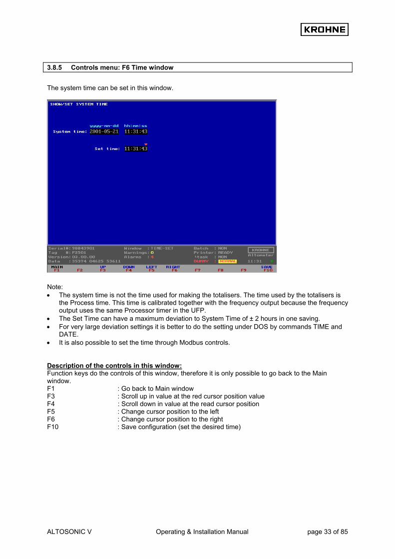
3.8.5 Controls menu: F6 Time window
The system time can be set in this window. Note: • The system time is not the time used for making the totalisers. The time used by the totalisers is
the Process time. This time is calibrated together with the frequency output because the frequency output uses the same Processor timer in the UFP.
• The Set Time can have a maximum deviation to System Time of ± 2 hours in one saving. • For very large deviation settings it is better to do the setting under DOS by commands TIME and
DATE. • It is also possible to set the time through Modbus controls. Description of the controls in this window: Function keys do the controls of this window, therefore it is only possible to go back to the Main window. F1 : Go back to Main window F3 : Scroll up in value at the red cursor position value F4 : Scroll down in value at the read cursor position F5 : Change cursor position to the left F6 : Change cursor position to the right F10 : Save configuration (set the desired time)

ALTOSONIC V Operating & Installation Manual page 34 of 85
3.8.6 Controls menu: F7 Reset Errors window
The manual reset of all alarms and warnings. Reset sequence: • Enable the reset by function key F2 • Confirm to reset by function key F3 It is also possible to reset by digital input signal or Modbus Boolean.

ALTOSONIC V Operating & Installation Manual page 35 of 85
3.8.7 Controls menu: F8 Reset Totalisers window
The manual reset of the resetable totalisers and all alarms and warnings. Reset sequence: • Enable the reset by function key F2 • Confirm to reset by function key F3 It is also possible to reset by digital input signal or Modbus Boolean.

ALTOSONIC V Operating & Installation Manual page 36 of 85
3.8.8 Controls menu: F10 Quit measure mode window
Window to terminate the measure mode and go to DOS mode. Quit sequence: • Confirm to quit function key F5 To proceed use function key F1 IMPORTANT: If the UFP-Program is stopped than there are no more flow measurements/calculations performed.

ALTOSONIC V Operating & Installation Manual page 37 of 85
3.9 Main menu: F10 Service window This is the start window for the Service windows where a description is given of the types of Service windows there are. Note that using this mode (SERVICE) is of no influence on flow measurements or calculations These Service windows are especially practical for debugging errors when an ALTOSONIC V system is set-up for Modbus and I/O signals (AD/DA).

ALTOSONIC V Operating & Installation Manual page 38 of 85
3.9.1 Service menu: F2 Interrupts window
Under normal circumstances it is not necessary to view this window. The Interrupt window is the lowest level PC activity monitor. The serviced interrupts are counted per source. Therefore the activity on for example a COM port for Modbus can easily be monitored for any signals coming in. The settings for the communication can be found in parameter file COMS0300.dat Default settings for the COM ports are: Irq 3: COM 4, Modbus for RS422/RS485. Irq 4: COM 3, RS 485 UFC DATA communication. If the Modbus communication is set up there must be activity on COM 4. If there is no activity then check the configuration in the COMS0300.dat and check the connections.

ALTOSONIC V Operating & Installation Manual page 39 of 85
3.9.2 Service menu: F3 UFC errors window
Under normal circumstances it is not necessary to view this window. All data shown here is also available in more common used windows in perhaps other formats or sublimated into less variables. The status is shown as counters per channel. There is no history in the counters so previous occurred errors will turn to zero. Communication errors per communication message (=per channel request): • Parity errors • Error in message length • Wrong start bytes • Framing error UART Communication status sublimated from communication errors per channel: • Channel state = 0: no errors (status normally) • Channel state = 1: error resulting in a single communication failure (COMFA) • Channel state = 2: comm. failures in succession resulting in a communication alarm (COMMU) Communication status regarding data skipped or already handled: • Old data : Counter for data, already handled(Note: normally toggles between 0 and 1). • Overrun : Counter for data, skipped because of system time shortage (note: cumulative!).

ALTOSONIC V Operating & Installation Manual page 40 of 85
3.9.3 Service menu: F4 UFC data
Under normal circumstances it is not necessary to view this window. All data shown here is also available in more common used windows in perhaps other formats. This window shows the raw basic flow data from the UFC-V with no history capacity. Data of all channels: • Transit time as [ms] • Flow rate as percentage [-125...+125%] • Line status (normally active, on communication failure Inactive) • Data status (New data, old data (previously handled), old data time out (on communication alarm))

ALTOSONIC V Operating & Installation Manual page 41 of 85
3.9.4 Service menu: F5 Modbus errors window
When setting up the UFP-V Modbus driver for communication this window is very useful for showing the occurred Modbus communication errors. The various errors are shown as historical counters per communication error. Under normal circumstances it is not necessary to view this window. When every counter is zero but the Modbus communication seems to fail first monitor the Interrupt window for any activity on the Comport. All data shown here is also available in more common used windows in perhaps other formats or sublimated into less variables.

ALTOSONIC V Operating & Installation Manual page 42 of 85
3.9.5 Service menu: F6 Modbus STATUS
When setting up the UFP-V Modbus driver for communication this window is very useful for showing addressed functions and responses. Under normal circumstances it is not necessary to view this window. Function 1 : Read coil Function 2 : Read input status Function 3 : Read multiple holding registers Function 4 : Read input registers Function 5 : Write single coil Function 6 : Write single holding register Function 8 : Diagnostics Function 15 : Write multiple coil Function 16 : Write multiple holding register

ALTOSONIC V Operating & Installation Manual page 43 of 85
3.9.6 Service menu: F7 Modbus data window
When setting up the UFP-V Modbus driver for communication this window is very useful for showing the available Modbus data fields in address and value for verifying data on both host side and UFP side per data register. Under normal circumstances it is not necessary to view this window.

ALTOSONIC V Operating & Installation Manual page 44 of 85
3.9.6.1 Service menu 2: F3 Modbus data1 window When setting up the UFP-V Modbus driver for communication this window is very useful for showing the available Modbus data fields in address and value for verifying data on both host side and UFP side per data register. Under normal circumstances it is not necessary to view this window
3.9.6.2 Service menu 2: F4 Modbus data2 window When setting up the UFP-V Modbus driver for communication this window is very useful for showing the available Modbus data fields in address and value for verifying data on both host side and UFP side per data register. Under normal circumstances it is not necessary to view this window

ALTOSONIC V Operating & Installation Manual page 45 of 85
3.9.6.3 Service menu 2: F5 Modbus data3 window When setting up the UFP-V Modbus driver for communication this window is very useful for showing the available Modbus data fields in address and value for verifying data on both host side and UFP side per data register. Under normal circumstances it is not necessary to view this window
3.9.6.4 Service menu 2: F6 Modbus data4 window When setting up the UFP-V Modbus driver for communication this window is very useful for showing the available Modbus data fields in address and value for verifying data on both host side and UFP side per data register. Under normal circumstances it is not necessary to view this window

ALTOSONIC V Operating & Installation Manual page 46 of 85
3.9.6.5 Service menu 2: F7 Modbus data5 window When setting up the UFP-V Modbus driver for communication this window is very useful for showing the available Modbus data fields in address and value for verifying data on both host side and UFP side per data register. Under normal circumstances it is not necessary to view this window
ALTOSONIC V Operating & Installation Manual page 47 of 85
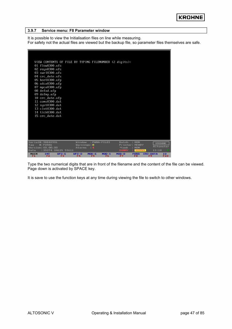
3.9.7 Service menu: F8 Parameter window
It is possible to view the Initialisation files on line while measuring. For safety not the actual files are viewed but the backup file, so parameter files themselves are safe. Type the two numerical digits that are in front of the filename and the content of the file can be viewed. Page down is activated by SPACE key. It is save to use the function keys at any time during viewing the file to switch to other windows.

ALTOSONIC V Operating & Installation Manual page 48 of 85
3.9.8 Service menu: F9 CRC-data window
As an extra service the CRC-checksums per file can be viewed, so in case of a change in a initialisation file it can be seen in this window which file has changed. Note that the CRC_NORM file CRC checksums are also at the bottom of the Status window This file holds the CRC checksums of the other files in the data set. So when anything changes in a file in the data set this also changes the CRC_NORM CRC-checksum.

ALTOSONIC V Operating & Installation Manual page 49 of 85
3.9.9 Service menu: F10 IO window
All secondary inputs and all outputs other then Modbus can be seen in this window Under normal circumstances it is not necessary to view this window. Input secondary signals The signals for temperatures pressures densities and viscosity can be input by AD Card, Modbus or Frequency Input. The configuration of these signals is in the CLNT0300.dat file. When setting up analog and digital I/O signals this window shows the signals for the AD card and MP103 card of the UFP-V. Per card functions can be enabled / disabled card through off-line software settings. AD card configuration : see chapters DATA ACQUISITION and OUTPUT MP103 card configuration : see chapters DATA ACQUISITION and OUTPUT

ALTOSONIC V Operating & Installation Manual page 50 of 85
4 CALCULATION OF STANDARD VOLUME AND MASS The principle of the UFP-V is measuring the volumetric Process flow rate. Integrating this value in time results in the volumetric Process total. Often measured quantities are compared. Because of temperature and pressure dependency of the volumetric Process it can be preferable to convert to more standard conditions: • Volumetric standard (1.01325 bar and for example 15°C). • Mass
4.1 Volumetric standard The correction of the volumetric Process to volumetric standard is done according to API/ASTM-IP standards. The volume correction factor VCF can be divided into: • Correction for the temperature dependency, using API 11.1 standard 2540 equation and
constants, resulting in a correction factor Ctl • Correction for the pressure dependency, using API 11.2.1M equation and constants, resulting in a
correction factor Cpl.
pltl CCVCF ⋅=
VCFVolVol procesds ⋅=tan VCF : Volume correction factor Ctl : Temperature correction factor Cpl : Pressure correction factor Volstand : Volumetric standard [m3] VolProcess : Volumetric Process [m3] Also available after calculation is the density at Process conditions. This means that mass is also calculated.
4.1.1 Calculation of correction temperature dependency Ctl
The correction for the temperature dependency to the 15°C reference base:
))]15(8.01()15([ −⋅⋅+⋅−⋅−= procesTprocesTtl TTEXPC αα Ctl : Temperature correction factor αT : Thermal expansion coefficient [1/°C] TProcess : Temperature Process [°C] In this, the equation is independent of the group or substance. It can be used with any valid method of obtaining the thermal expansion coefficient for a given fluid, as long as a statistically significant number of points is obtained. A minimum of ten such points is recommend. In addition, the values of the constants K0, K1 and K2 are given for each major group. These constants relate the thermal expansion coefficient to base density by :
215
12
15
0 KKKT ++=
ρρα
αT : Thermal expansion coefficient [1/°C] ρ15 : Density at reference 15 °C [kg/m3] K0, K1, K2 : Constants, depending on the type of the product

ALTOSONIC V Operating & Installation Manual page 51 of 85
The API table for the 15°C reference base as installed in the UFP-V is: Type of product Low limit ρ15
[kg/m3] High limit ρ15
[kg/m3] K0 K1 K2
Crude 610.5 1075.0 613.9723 0 0 Gasoline 653.0 770.0 346.4228 0.4388 0 Trans.area 770.5 787.5 2680.3206 0 -0.00336312 Jet group 788.0 838.5 594.5418 0 0 Fuel oil 839.0 1075.0 186.9696 0.4862 0 Free fill in 500.0 2000.0 0 0 0
Practical rule: The correction per °C is approximately 0.05% - 0.15% depending on conditions and type of product. Standard temperature different from 15°C: The method is based on a reference standard of 15°C. For example if the Process temperature is 65°C.
1565→= tltl CC
If the required standard temperature is different from 15°C the correction for the difference is introduced. For example if the standard temperature is 20°C,
1520
1565
→
→=tl
tltl C
CC
Note: If the standard temperature is different from 15°C the density limits per product type also change. The UFP-V calculates the limitations for the installed standard temperature. A density can not be filled in beyond limitations. The Free Fill product type is for uncommon products, K0, K1 K2 are adjustable.
4.1.2 Calculation of correction pressure dependency Cpl
The basic mathematical model, used to develop this standard, relates the compressibility factor exponentially to temperature and the square of the molecular volume. That is:
]10
0042092.0
1087096.000021592.062080.1[
6215
6215
−− ⋅
⋅+
⋅+⋅+−=
ρρproces
proces
TTEXPF
F : Compressibility factor, [1/kPa] TProcess : Temperature Process [°C] ρ15 : Density at 15 °C [kg/m3] The compressibility factor F is used in the normal manner of volume correction to make the correction for the pressure effect:
41011
−⋅⋅−=
procespl PF
C
Cpl : Pressure correction factor F : Compressibility factor PProcess : Pressure Process [bar] Practical rule: The correction per bar is approximately 0.005% - 0.015% depending on conditions and product.
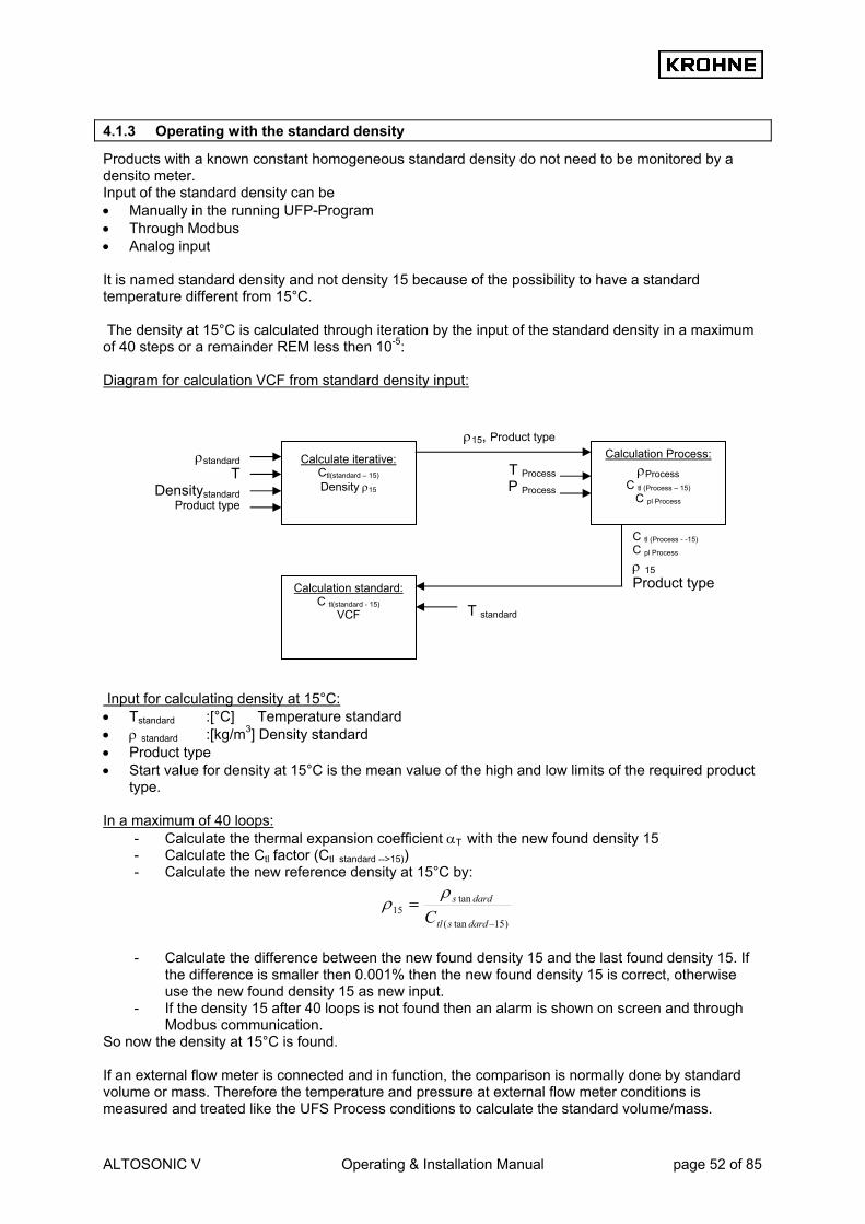
ALTOSONIC V Operating & Installation Manual page 52 of 85
4.1.3 Operating with the standard density
Products with a known constant homogeneous standard density do not need to be monitored by a densito meter. Input of the standard density can be • Manually in the running UFP-Program • Through Modbus • Analog input It is named standard density and not density 15 because of the possibility to have a standard temperature different from 15°C. The density at 15°C is calculated through iteration by the input of the standard density in a maximum of 40 steps or a remainder REM less then 10-5: Diagram for calculation VCF from standard density input: Input for calculating density at 15°C: • Tstandard :[°C] Temperature standard • ρ standard :[kg/m3] Density standard • Product type • Start value for density at 15°C is the mean value of the high and low limits of the required product
type. In a maximum of 40 loops:
- Calculate the thermal expansion coefficient αT with the new found density 15 - Calculate the Ctl factor (Ctl standard -->15)) - Calculate the new reference density at 15°C by:
)15tan(
tan15
−
=dardstl
dards
Cρ
ρ
- Calculate the difference between the new found density 15 and the last found density 15. If
the difference is smaller then 0.001% then the new found density 15 is correct, otherwise use the new found density 15 as new input.
- If the density 15 after 40 loops is not found then an alarm is shown on screen and through Modbus communication.
So now the density at 15°C is found. If an external flow meter is connected and in function, the comparison is normally done by standard volume or mass. Therefore the temperature and pressure at external flow meter conditions is measured and treated like the UFS Process conditions to calculate the standard volume/mass.
ρstandard T
Densitystandard Product type
ρ15, Product type T ProcessP Process
Calculation Process: ρProcess
C tl (Process – 15) C pl Process
Calculation standard:C tl(standard - 15)
VCF
T standard
C tl (Process - -15) C pl Process
ρ 15 Product type
Calculate iterative: Ctl(standard – 15) Density ρ15

ALTOSONIC V Operating & Installation Manual page 53 of 85
4.1.4 Operating with the measured density
For less homogenous products like Crudes it is more practical to measure the density. The density at 15°C is calculated through iteration by the input of the measured density in a maximum of 40 steps or a remainder REM less then 10-5. Diagram for calculation VCF from measured density input: Input for calculating density at 15°C: • Tdens :[°C] Temperature densito meter • Pdens :[bar] Pressure densito meter • ρ dens :[kg/m3]Density densito meter (measured density) • Product type • Start value for density at 15°C is the mean value of the high and low limits of the required product
type. In a maximum of 40 loops:
- Calculate the thermal expansion coefficient αT with the new found density15 - Calculate the Ctl factor (Ctl Tdens -->15)) - Calculate the Cpl factor.(Cpl Pdens) - Calculate the new density at 15°C by:
pldenstldens
dens
CC ⋅=
ρρ15
- Calculate the difference between the new found density15 and the last found density15. If
the difference is smaller then 0.001% then the new found density15 is correct, otherwise use the new found density15 as new input.
- If the density15 after 40 loops is not found then an alarm is shown on screen and through Modbus communication.
So the density at 15°C is found. Practically the conditions (T, P) for the densito meter can differ from the conditions of the measured flow rate in the UFS-V. Therefore, the VCF that is eventually used, is calculated using the found density at 15°C as its base and the conditions of the measured flow rate as its goal. If an external flow meter is connected and in function, the comparison is normally done by standard volume or mass. Therefore the temperature and pressure at external flow meter conditions are measured and treated like the UFS Process conditions to calculate the standard volume/mass.
T dens P de
ρ dens
Product type
Calculate iterative: density ρ15
(15°C, 1.01325 bar)
ρ15, Product type T ProcessP Process
Calculation Process: ρProcess
C tl Process-->15 C pl Process
Calculation standard:C tl standard-->15
VCF
T standard
C tl Process-->15 C pl Process
ρ 15 Product type
T dens Pdens ρDensitometer Product type

ALTOSONIC V Operating & Installation Manual page 54 of 85
4.2 Mass calculation For mass calculation without using API standard volume calculations for the Process density it is of great importance that its measurement conditions are approximately similar to the measurement conditions of the flow rate in the UFS.
ρφφ ⋅= vm Φm : Mass flow rate [kg/hr], the unit used in UFP is [ton/hr], 1 [ton] is 1000 [kg] Φv : Volume flow rate at Process conditions ρ : Density at Process conditions [kg/m3] Any deviation in measured density as function of the measurement conditions is directly proportional in the calculation of the mass flow rate. For example: Crude oil with flow measurement at 25 °C and density measurement at 24°C. Density 25°C: 845.00 kg/m3 Density 24°C: 845.71 kg/m3 This gives a deviation in mass flow rate of:
%08.0100845
84571.845=⋅
−
So variations of the measurement conditions for densitometer position to flow rate position will effect linearity and repeatability of the mass measurement. When this problem occurs it is better to use the API standard volume calculation for its mass calculation. Its a little more complicated but then there is a correction for the measurement conditions.
4.3 Solartron meter density is calculated as follows:
Density calibration at 20 °C, 1 barA. Density temperature and pressure corrected:
2210 TKTKKD ⋅+⋅+=
)20(19))20(181( −+−+= tKtKDDt
)1(21))1(201( −+−+= PKpKDD tp
Where K20 and K21 are: )1(202020 −+= pBKAKK
)1(212121 −+= pBKAKK D : Density, uncorrected [kg/m3] Dt : Density, temperature corrected [kg/m3] Dp : Density, pressure corrected [kg/m3] T : Periodic time [µs] t : Temperature [°C] p : Pressure [barA] K0, K1, K2 : Calibration factors, Density calibration at 20 °C, 1 barA. K18, K19 : Calibration factors, Density calibration at 20 °C, 1 barA. K20A,K20B : Calibration factors, Density calibration at 20 °C, 1 barA. K21A,K21B : Calibration factors, Density calibration at 20 °C, 1 barA. The calibration factors can be altered on-line while the system is operating, by keyboard (CONTROLS F9, DENSITO F5) or by Modbus control.

ALTOSONIC V Operating & Installation Manual page 55 of 85
4.4 Sarasota meter density is calculated as follows:
)()(0'
0 calpcalt ppNttNTT −+−+=
)2( '0
'0
'0
'0
0 TTTK
TTTDm
−⋅+⋅
−⋅=ρ
ρm : Calculated measured mass density of fluid [kg/m3] T : Measured periodic time [µs] T0‘ : Corrected value of T0 [µs] T0 : Calibration factor, reference periodic time [µs] of spool at 15°C and zero density t : Absolute temperature [K] tcal : Calibration factor, calibration temperature used in density calculations [15°C] p : Absolute pressure [bar] pcal : Calibration factor, calibration pressure used in density calculations [1.01325 bar] Nt : Calibration factor, temperature coefficient of spool [µs/K] Np : Calibration factor, pressure coefficient of density transducer [µs/bar] D0 : Calibration factor, calibration constant of spool [kg/m3] K : Calibration factor, spool calibration constant [ ] The calibration factors can be altered on-line while the system is operating, by keyboard (CONTROLS F9, DENSITO F5) or by Modbus control.
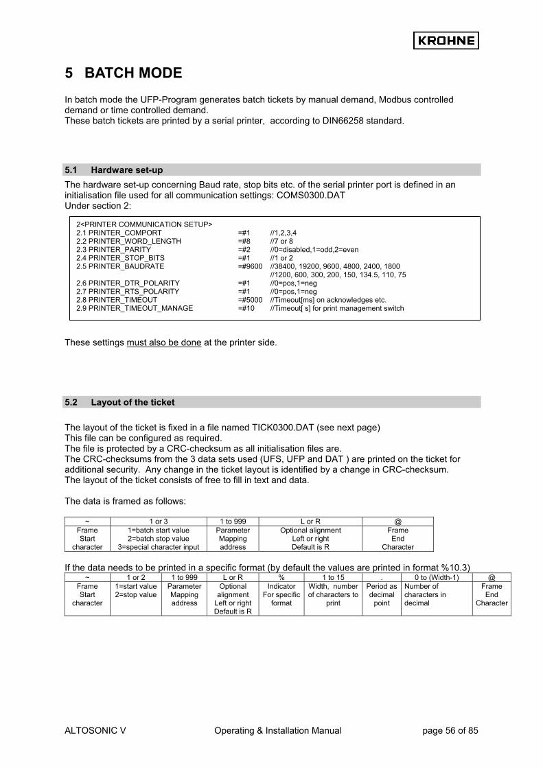
ALTOSONIC V Operating & Installation Manual page 56 of 85
5 BATCH MODE In batch mode the UFP-Program generates batch tickets by manual demand, Modbus controlled demand or time controlled demand. These batch tickets are printed by a serial printer, according to DIN66258 standard.
5.1 Hardware set-up The hardware set-up concerning Baud rate, stop bits etc. of the serial printer port is defined in an initialisation file used for all communication settings: COMS0300.DAT Under section 2: These settings must also be done at the printer side.
5.2 Layout of the ticket The layout of the ticket is fixed in a file named TICK0300.DAT (see next page) This file can be configured as required. The file is protected by a CRC-checksum as all initialisation files are. The CRC-checksums from the 3 data sets used (UFS, UFP and DAT ) are printed on the ticket for additional security. Any change in the ticket layout is identified by a change in CRC-checksum. The layout of the ticket consists of free to fill in text and data. The data is framed as follows:
~ 1 or 3 1 to 999 L or R @ Frame Start
character
1=batch start value 2=batch stop value
3=special character input
Parameter Mapping address
Optional alignment Left or right Default is R
Frame End
Character If the data needs to be printed in a specific format (by default the values are printed in format %10.3)
~ 1 or 2 1 to 999 L or R % 1 to 15 . 0 to (Width-1) @ Frame Start
character
1=start value 2=stop value
Parameter Mapping address
Optional alignment
Left or right Default is R
Indicator For specific
format
Width, number of characters to
Period as decimal
point
Number of characters in decimal
Frame End
Character
2<PRINTER COMMUNICATION SETUP> 2.1 PRINTER_COMPORT =#1 //1,2,3,4 2.2 PRINTER_WORD_LENGTH =#8 //7 or 8 2.3 PRINTER_PARITY =#2 //0=disabled,1=odd,2=even 2.4 PRINTER_STOP_BITS =#1 //1 or 2 2.5 PRINTER_BAUDRATE =#9600 //38400, 19200, 9600, 4800, 2400, 1800 //1200, 600, 300, 200, 150, 134.5, 110, 75 2.6 PRINTER_DTR_POLARITY =#1 //0=pos,1=neg 2.7 PRINTER_RTS_POLARITY =#1 //0=pos,1=neg 2.8 PRINTER_TIMEOUT =#5000 //Timeout[ms] on acknowledges etc. 2.9 PRINTER_TIMEOUT_MANAGE =#10 //Timeout[ s] for print management switch

ALTOSONIC V Operating & Installation Manual page 57 of 85
Example of ticket layout in file TICK0300.dat: For the specific parameter mapping addresses see next paragraph.
~3027@~3087@~3049@ KROHNE Altometer ~3027@~3087@~3048@ IDENTIFICATION Ticket number : ~1001L@ Start time : ~1101L@ Stop time : ~2101L@ Serial number : ~1201L@ Software version : ~1202L@ Tag number ID : ~1203L@ Batch ID : ~1204L@ Batch name : ~1205L@ TOTALISERS Process[m3] Standard[m3] Mass[tonM] Start Cum. :~1401R%10.2@ ~1404R%10.2@ ~1407R%10.2@ Stop Cum. :~2401R%10.2@ ~2404R%10.2@ ~2407R%10.2@ Batch :~2301R%10.2@ ~2304R%10.2@ ~2307R%10.2@ BATCH FLOW WEIGHTED AVERAGES Temperature[°C] Pressure[bar] Density [kg/m3] Process : ~2502R%8.2@ ~2505R%8.2@ ~2520R%9.3@ Densito meter : ~2504R%8.2@ ~2507R%8.2@ ~2508R%9.3@ Standard : ~2519R%8.2@ ~2509R%9.3@ CONFIGURATION ON STANDARD VOLUME CALCULATION Calculation Method : ~2701L@ Temperature standard [°C] : ~2702L%5.2@ Density standard by : ~2703L@ Api group fluid type : ~2704L@ API correction factor K0 : ~2705L%11.4@ API correction factor K1 : ~2706L%11.4@ API correction factor K2 : ~2707L%11.8@ ALARMS Measured[s] Override[s] Temperature Body : ~2606R%10.1@ ~2616R%10.1@ Temperature Process : ~2607R%10.1@ ~2617R%10.1@ Temperature Densitometer : ~2609R%10.1@ ~2619R%10.1@ Pressure Process : ~2610R%10.1@ ~2620R%10.1@ Pressure Densitometer : ~2612R%10.1@ ~2622R%10.1@ Density Process : ~2613R%10.1@ ~2623R%10.1@ Density Standard : ~2614R%10.1@ ~2624R%10.1@ General Flow 1-4 channels down : ~2601R%10.1@ General Flow all channels down : ~2602R%10.1@ Calculation API group mismatch : ~2603R%10.1@ System runtime alarms occurred : ~2604R%10.1@ Realtime Profile out of range : ~2605R%10.1@

ALTOSONIC V Operating & Installation Manual page 58 of 85
5.3 Parameter mapping addresses
5.3.1 Ticket number 1 Non resetable sequence number for the batch 2 … 99 reserved
5.3.2 Times 101 Time and date of start and stop 102 ... 199 reserved
5.3.3 Operate names (optional at batch set-up) 201 Serial number (internal) 202 Software version (internal) 203 Tag number ID (internal) 204 Batch ID (fill in optional) 205 Batch name/source (fill in optional) 206 Batch reference number (only accessible by Modbus input) 207 ... 299 reserved
5.3.4 Resetable Totalisers (at start and stop time) 301 Resetable Actual Totaliser 302 Resetable Actual forward Totaliser 303 Resetable Actual reverse Totaliser 304 Resetable Standard Totaliser 305 Resetable Standard forward Totaliser 306 Resetable Standard reverse Totaliser 307 Resetable Mass Totaliser 308 Resetable Mass forward Totaliser 309 Resetable Mass reverse Totaliser 310 Resetable External Flow meter Standard Totaliser 311 Resetable External Flow meter Standard Forward Totaliser 312 Resetable External Flow meter Standard Reverse Totaliser 313.. 399 reserved
5.3.5 Non Resetable Totalisers (at start and stop time) 401 Non resetable Actual Totaliser 402 Non resetable Actual Forward Totaliser 403 Non resetable Actual Reverse Totaliser 404 Non resetable Standard Totaliser 405 Non resetable Standard Forward Total 406 Non resetable Standard Reverse Total 407 Non resetable Mass Totaliser 408 Non resetable Mass Forward Totaliser 409 Non resetable Mass Reverse Totaliser 410..499 reserved
5.3.6 Batch Flow weighted averages 501 Batch 1 average temperature body 502 Batch 1 average temperature Process 503 Batch 1 average temperature proving external flow meter 504 Batch 1 average temperature densito meter 505 Batch 1 average pressure Process 506 Batch 1 average pressure proving external flow meter 507 Batch 1 average pressure densito meter 508 Batch 1 average density densito meter 509 Batch 1 average density standard 510 Batch 1 average External Viscosity dynamic 511 Batch 1 average Ctl (15°C to Process) 512 Batch 1 average Cpl (0 Bar to Process) 513 Batch 1 average Ctl (15°C to standard ) 514 Batch 1 average Cpl (0 Bar to standard, always 1) 515 Batch 1 average Ctl (15°C to densito meter ) 516 Batch 1 average Cpl (0 Bar to densito meter)

ALTOSONIC V Operating & Installation Manual page 59 of 85
517 Batch 1 average Ctl (15°C to proving external flow meter) 518 Batch 1 average Cpl. (0 Bar to proving external flow meter) 519 Batch 1 average temperature standard 520 Batch 1 average density Process 521 Batch 1 average flow actual 522 Batch 1 average density proving external flow meter 523 Batch 1 average flow proving external flow meter 524 Batch 1 average Installed K factor proving external flow meter 525 Batch 1 found New K factor proving external flow meter 526 Batch 1 difference installed vs new found K factor external 527…599 reserved
5.3.7 Batch alarms in seconds: 601 Batch 1 alarm: General Flow 1-4 channels down 602 Batch 1 alarm: General Flow all channels down 603 Batch 1 alarm: calculation API group mismatch 604 Batch 1 alarm: system runtime alarm occurred 605 Batch 1 alarm: real time profile out of range when used 606 Batch 1 alarm: measured Body temperature out of range 607 Batch 1 alarm: measured Process temperature out of range 608 Batch 1 alarm: measured External Prove temperature out of range 609 Batch 1 alarm: measured Densito temperature out of range 610 Batch 1 alarm: measured Process pressure out of range 611 Batch 1 alarm: measured External Prove pressure out of range 612 Batch 1 alarm: measured Densito pressure out of range 613 Batch 1 alarm: measured Densito Density out of range 614 Batch 1 alarm: measured Standard Density out of range 615 Batch 1 alarm: measured External viscosity out of range 616 Batch 1 alarm: override Body temperature applied 617 Batch 1 alarm: override Process temperature applied 618 Batch 1 alarm: override External Prove temperature applied 619 Batch 1 alarm: override Densito temperature applied 620 Batch 1 alarm: override Process pressure applied 621 Batch 1 alarm: override External Prove pressure applied 622 Batch 1 alarm: override Densito pressure applied 623 Batch 1 alarm: override Densito Density applied 624 Batch 1 alarm: override Standard Density applied 625 Batch 1 alarm: override External viscosity applied 626…699 reserved
5.3.8 Configuration API etc 701 Calculation method: Only Process flow, Standard volume/mass by API standards, mass measurement by Process density 702 Temperature standard in value 703 Density standard by: fill in manually, calculated from densito meter density, on AD / Modbus input 704 Fluid type: crude, gasoline, trans. area, jet group, fuel oil, free fill 705 API correction factor K0 706 API correction factor K1 707 API correction factor K2 708..799 reserved
5.3.9 Security 801 CRC checksum on data set UFS 802 CRC checksum on data set UFP 803 CRC checksum on data set DAT 804..999 reserved
5.3.10 Special characters for printer control
Special characters for printer control start with a 3. The so called escape codes for printer control can be inserted into the Ticket Layout Examples: ~3007@ Printer sounds a bel ~3012@ Formfeed ~3027@~3067@~3000@~30xx@ Set page length in inch in ~30xx@: xx=1…22 ~3027@~3067@~3000@~3xxx@ Set page length in lines in ~3xxx@: xx=1…127 ~3027@~3087@~3049@ Select double sized characters ~3027@~3087@~3048@ Cancel double sized characters

ALTOSONIC V Operating & Installation Manual page 60 of 85
~3027@~3071@ Select double strike printing ~3027@~3072@ Cancel double strike printing ~3027@~3052@ Select italic characters ~3027@~3053@ Cancel italic characters ~3027@~3054@ Cancel italic characters ~3027@~3057@ Enable paper out sensor ~3027@~3056@ Disable paper out sensor
5.4 Initial batch set-up The initial batch set-up is by initialisation file CLNT0300.dat file under section 12: • There are 3 modes for Batch configuration:
BATCHING ON
Start stop batch permission
Confirmation asked on batch settings
API settings during batch possible
0 Batch mode disabled ------- ------ 1 Only at zero flow
conditions Yes No
2 At all flowing conditions Yes No 3 At all flowing conditions No Yes (continuous pipe
line measurement) BATCHING_ON 1 and 2 have the following restrictions during a batch: -No reset possible of resetable totalisers -No reset of error times but the possibility to reset occurred error messages
• The previous number of tickets saved is set with MAX_TICKETS. Default is 100 tickets.
Be careful with increasing the number of tickets. Not enough disk space means losing tickets • For Continuous Pipe Line Measurement the ticket automatically is printed starting from
HOUR_START • For Continuous Pipe Line Measurement the ticket automatically is printed every
HOUR_INTERVAL, but if interval 0 is installed than tickets are only printed on demand • By MOD_BUS_CONTROL it is possible to enable the controls through Modbus for batching:
-Start batch -Stop batch -Reset printing -Confirm printing
12 <BATCHING CONTROL> Only in use when a Epson Serial Printer according DIN66258 standard is connected. Note that in the HSET0300.UFP file (for hardware setup) the following data must be set: -1.4 Location_stat must be enabled (saving of status) -1.8 Location_tic must be a disk with enough storage capacity 12.1 BATCHING_ON =#2 //0=Internal batching disabled //1=Enable Batching (start stop at zero flow) //2=Enable Batching (start stop at all flows) //3=Enable Batching (continuous pipe line) auto reset //4=Enable Batching (continiuous pipe line) no reset at end //If enabled then automatic initialize printer 12.2 Max_tickets =#100 //Maximum number of last tickets saved 10..100000 //depending on disk space (see Location_tic above) 12.3 Hour_start =#10 //Start hour 0..23 for continous pipe line ticket 12.4 Hour_interval =#1 //Interval hour 1..24 for continous pipe line ticket //0=No tickets automatic, only on demand 12.5 Modbus_control =#1 //Control batching through modbus

ALTOSONIC V Operating & Installation Manual page 61 of 85
Or in case of using continuous Pipe Line measurement -Ticket on demand with reset of values -Ticket on demand without reset of values
- Reset printing
5.5 Batch status Batch status (status window text)
As a value on Modbus
Explanation
NON 0 No batch active, ready to set-up SETUP 1 In set-up mode. After set-up is done, it is possible to
start a batch RUNNING 2 Batch is started
END-BATCH 3 Batch is stopped and ticket is made, then attempt to END_PRINT
END-PRINT 5 Status during successful printing END-FAIL 6 If printing fails or printer is busy too long CONFIRM 7 After successful print job waiting for manual
confirmation RESET 10 Waiting for reset command after END_FAIL
5.6 Printer status Printer status (status window text)
As a value on Modbus
Explanation
Ready 0 Ready for printing Fail 1 If printer failed during print job
Busy Check
2 2
During print job If no print job, check if printer is connected and ready
Off 3 If printer is not found after Check
5.7 Printer task status Printer status (status window text)
As a value on Modbus
Explanation
NON 0 No print job BUSY 1..2 Attempt first character
Xxxs …0s Timeout print management Value in seconds counting
down, if 0 then status to RESET
3 Getting acknowledge if printer is taking print job. For multiple UFP’s connected by a printer switch to 1 serial printer. Timeout print management can be set in COMS0300.dat under section 2.9
BUSY 4..98 Printing headers Progress counter as percentage 0…100
99 Successful printing ticket
CONFIRM 100 Ready to confirm print job, see batch status CONFIRM RESET 101 Ready for reset command on batch status RESET

ALTOSONIC V Operating & Installation Manual page 62 of 85
5.8 Batch set-up BATCHING_ON 1 or 2 is a normal batch that requires batch set-up: A new batch can only be set if the last batch is stopped and the ticket is printed correctly and confirmed Start the set-up by pressing function key F2 for confirmation on the API settings
5.8.1 API set-up
The operator is forced to look at the API setting. He can change the settings and SAVE by F10 or return back to BATCH by F1. If the batch is controlled by Modbus this step must be handled by the Host system.

ALTOSONIC V Operating & Installation Manual page 63 of 85
5.8.2 Batch text set-up
On returning from API settings the strings can be set: Returning to batch means confirmation on texts Confirmation on Batch ID and Batch name/source is only possible with manual set-up Note that the Modbus data is only numerical, so Modbus can not set Batch ID and Batch Name.
5.8.3 Ready to start batch after set-up is complete
• Now batch is ready to start by Function key F10 or by Modbus command if enabled. Note that
depending on security level it is only possible to start a batch if flow is at zero flow conditions • Possible to cancel the set-up (F2) • Or return to the API settings (F3) or the Text settings (F4)

ALTOSONIC V Operating & Installation Manual page 64 of 85
5.9 Batch start Starting a batch holds the following automatic actions: • Reset of : errors, resetable totalisers and batch flow-weighted averages (temp, press, densities
etc.) • Increase ticket number by one (is saved in the “batch status” file. • Saving of all batch parameters (for later use when batch is stopped and certain batch start values
are requested on ticket) in a “batch start” file that is secured by a CRC-checksum

ALTOSONIC V Operating & Installation Manual page 65 of 85
5.10 During batch During a batch the restrictions are handled as the installed BATCHING_ON level prescribes. Files with all alarm times, totalisers, and batch averages are saved every 20 seconds to a SRAM disk in dual files. Sequentially saving it each time in a different file. So when the power is turned of during a file-save causing the file to be corrupted, the previously saved dual file is used at start-up to load previously saved alarm times, totalisers, and batch averages.
5.10.1 Reading / Printing previous batch ticket
During a batch it is possible to read and print a previous batch ticket From Main window to Batch Control window by F7 and then Function Key F2 for reading previous batch ticket Explanation Function keys: F1 : Back to Main Window F2 : Return to Batch Control window F3 : Upload “Ticket to read “ F4…F7 : Change “Ticket to read” number within the limits of “Tickets available”

ALTOSONIC V Operating & Installation Manual page 66 of 85
5.10.1.1 Read ticket Notice that the ticket that is read is not valid: The header explains that there were system errors. The System errors are mentioned at the bottom of the ticket therefore in this example the reading of the ticket is scrolled down to the bottom. Function keys: F1 : back to Main window F2 : back to Batch control F3 : Scroll up in ticket F4 : Scroll down in ticket F9 : Print the ticket F10 : Read another ticket

ALTOSONIC V Operating & Installation Manual page 67 of 85
5.11 Batch stop After starting a batch, this batch can be stopped manually in the Batch Control window by F8, or by Modbus command if enabled Note that depending on security level it is only possible to stop a batch if flow is at zero conditions Stopping a batch holds the following automatic actions: • Saving of all parameters possible (in values) on ticket in a “batch stop” file that is secured by a
CRC-checksum. • Make and save ticket according to the “layout ticket” file that is secured by a CRC-checksum • If saving of the ticket failed a message will appear on screen and on the ticket. • The ticket will be send to the printer after saving the ticket In the picture above the batch is ended and is just started to print. Batch status : END PRINT Printer status : BUSY Printer task at : 011% It is always possible to reset the printer buffer in the UFP, this will cause the print task to start at the beginning of the ticket again. Note that it can be necessary to reboot the printer itself on a real print failure. Stopping a batch holds the following “manual actions” / “ModBus commands”: • After ticket is printed, confirm the printed ticket is printed successful and is the same as shown on
screen.

ALTOSONIC V Operating & Installation Manual page 68 of 85
• If the printing has failed the software generates an alarm and no confirmation can be given only a reset of the printer. Check and reset the printer. After reset, the complete ticket is printed again. If the ticket is printed correct a confirmation can be given.
Note that a next batch can only be started when the previous batch is confirmed. If any CRC is corrupted this will be indicated on the ticket Printout • In the header of the ticket, that the ticket is invalid due to system errors • At the end of the ticket, the explanation of the system errors and so that there was a crc checksum
failure If status batch files are all corrupt at initialisation of the UFP-Program, a new status file is made. The ticket number can then be set to desired value (for logistical reasons) and the DAT data set will have CRC checksum update.
5.11.1 Possible errors that cause an Invalid Batch ticket
In the header of the ticket one of the 3 following messages will be printed • Decisive presentation: Valid • Decisive presentation: Not valid, crc-checksum error (ticket) • Decisive presentation: Not valid, system errors during batch At the end of the ticket, there will be an explanation of the system errors if they have occurred: Error in batch by: • During read/write of start/stop value files • During making ticket file (write errors) • During batch: batch status files • During batch: batch totaliser files • During batch: batch average files • During batch: system stopped during batch • During batch: measurement alarms possibly cause > 0.04 percent deviation • During batch: batch status file saving

ALTOSONIC V Operating & Installation Manual page 69 of 85
5.11.2 Measurement alarms batch validation
To validate a batch when a measurement alarm has occurred over a period of time (Alarm in [s]) the following calculation is used to validate the batch within a 0.04% error.
100[%]][
3600]/3[]3[_ ErrorsAlarmhmMaxFlowmerrorVolume ⋅⋅=
[%]100]3[__
]3[_[%] ⋅=mprocesVolumeBatch
merrorVolumeDeviation
Secondary inputs measurement Error% on occurred alarm: Secondary inputs Error% Explanation Temperature body 2 10°C is 0.036% deviation: 2% caused by >500°C Temperature Process 50 1°C is 0.1% deviation: 50% caused by 500°C deviation Temperature proving external flow meter 50 1°C is 0.1% deviation: 50% caused by 500°C deviation Temperature densito meter 50 1°C is 0.1% deviation: 50% caused by 500°C deviation Pressure Process 5 1 bar is 0.01% deviation: 5% caused by 500 bar deviation Pressure proving external flow meter 5 1 bar is 0.01% deviation: 5% caused by 500 bar deviation Pressure densito meter 5 1 bar is 0.01% deviation: 5% caused by 500 bar deviation Density densito meter 100 Standard volume correction uncertain therefore 100% errror Density standard 100 Standard volume correction uncertain therefore 100% errror UFP measurement Error% on occurred alarm: Secondary inputs Error% Explanation 1-4 channels down 10 Correction curve over viscosity never > 5%. To secure validity value=10% All channels down 100 System is not measuring flow therefore 100% error API group mismatch 100 Standard volume correction uncertain therefore 100% errror System alarms 10 Over estimated value on alarms as file not found, overrun etc Real time profile out of range 10 Correction curve over viscosity never > 5%. To secure validity value=10% Each alarm is measured in seconds, and the Volume_Error it causes, is calculated. All Volume_error values are summated and the total deviation is calculated. Example: How long may a certain error be active during a batch before the batch is Not Valid: • Only alarm 1-4 channels down: alarm time is x • Maximum flow rate is 1200m3/h • Batch time is 24 hours at 80% of the maximum flow rate
The batch volume in 24 hours at 80% flow rate:
]3[23040]/3[1200100
[%]80][24]3[Pr__ mhmhmocesVolumeBatch =⋅⋅=
For the alarm “1-4 channels down” to be within 0.04% :
]3[216.9]3[23040100
[%]04.0max__ mmerrorVolume =⋅=
][276[%]10
100]/3[1200
3600]3[216.9][ shm
msAlarm =⋅⋅=
ALTOSONIC V Operating & Installation Manual page 70 of 85
5.12 Continuous Pipeline Measurement tickets When the BATCHING_ON mode is on Continuous Pipeline Measurement no confirmations are asked after printing the ticket. If a new ticket has failed in printing it is asked to reset. But if no reset is made then the next ticket will just make the reset and start printing the next ticket. The previous ticket can then be printed as described in paragraph: Reading / Printing previous batch ticket There are two options for continuous Pipeline measurement: 3 Auto reset of totalisers, errors, averages etc between tickets 4 No auto reset of totalisers, errors, averages etc between tickets, but possible on demand. (clnt0300.dat file section 12.1 option 3 or 4) For Continuous Pipe Line Measurement the ticket automatically is printed starting from HOUR_START (clnt0300.dat file section 12.3) For Continuous Pipe Line Measurement the ticket automatically is printed every HOUR_INTERVAL, but if interval 0 is installed than tickets are only printed on demand (clnt0300.dat file section 12.4)
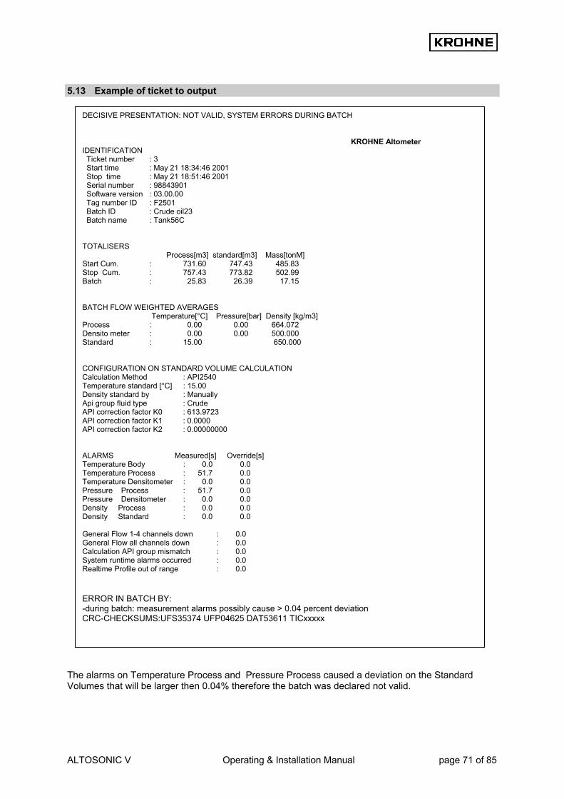
ALTOSONIC V Operating & Installation Manual page 71 of 85
5.13 Example of ticket to output The alarms on Temperature Process and Pressure Process caused a deviation on the Standard Volumes that will be larger then 0.04% therefore the batch was declared not valid.
DECISIVE PRESENTATION: NOT VALID, SYSTEM ERRORS DURING BATCH
KROHNE Altometer IDENTIFICATION Ticket number : 3 Start time : May 21 18:34:46 2001 Stop time : May 21 18:51:46 2001 Serial number : 98843901 Software version : 03.00.00 Tag number ID : F2501 Batch ID : Crude oil23 Batch name : Tank56C TOTALISERS Process[m3] standard[m3] Mass[tonM] Start Cum. : 731.60 747.43 485.83 Stop Cum. : 757.43 773.82 502.99 Batch : 25.83 26.39 17.15 BATCH FLOW WEIGHTED AVERAGES Temperature[°C] Pressure[bar] Density [kg/m3] Process : 0.00 0.00 664.072 Densito meter : 0.00 0.00 500.000 Standard : 15.00 650.000 CONFIGURATION ON STANDARD VOLUME CALCULATION Calculation Method : API2540 Temperature standard [°C] : 15.00 Density standard by : Manually Api group fluid type : Crude API correction factor K0 : 613.9723 API correction factor K1 : 0.0000 API correction factor K2 : 0.00000000 ALARMS Measured[s] Override[s] Temperature Body : 0.0 0.0 Temperature Process : 51.7 0.0 Temperature Densitometer : 0.0 0.0 Pressure Process : 51.7 0.0 Pressure Densitometer : 0.0 0.0 Density Process : 0.0 0.0 Density Standard : 0.0 0.0 General Flow 1-4 channels down : 0.0 General Flow all channels down : 0.0 Calculation API group mismatch : 0.0 System runtime alarms occurred : 0.0 Realtime Profile out of range : 0.0 ERROR IN BATCH BY: -during batch: measurement alarms possibly cause > 0.04 percent deviation CRC-CHECKSUMS:UFS35374 UFP04625 DAT53611 TICxxxxx

ALTOSONIC V Operating & Installation Manual page 72 of 85
6 DATA ACQUISITION
Input data can be divided into: • Data input RS485 card • Digital inputs MP103 card • Frequency inputs MP103 card • Analog inputs AD card
6.1 Data input RS485 card The data measured by the five converters UFC-V is transferred to the UFP-V by using a half-duplex protocol based on balanced data transmission (RS485). The communication protocol requests the five converters for new measured data. The incoming data is first checked on parity-errors, framing-errors, and overruns. The data essentially contains the measured flow from 5 ultrasonic measuring paths, transit time, and error codes. The converter sends data every 35 ms.
1 2 3 4 5
RS 485 card in UFP
Requests to UFC converters 1..5
Reply of UFC converters 1..5 - Flow percentage –125..+125%- Transit time - Status overrange - Status path failure

ALTOSONIC V Operating & Installation Manual page 73 of 85
6.2 Digital inputs MP103 card The MP103 card has 4 digital inputs. The digital inputs are normally open (is 0) The logic level is TTL compatible, maximum 12 VDC. Channel no.
Function Action
0 Reset measured volume, Process-time and error messages Make input ‘1’ to reset 1 Reset error messages Make input ‘1’ to reset 2 Calibration start-signal (KROHNE Altometer use only) Make input ‘1’ to arm, make ‘0’ to enable 3 Calibration stop-signal (KROHNE Altometer use only) Make input ‘1’ to arm, make ‘0’ to enable
• The digital input function can be disabled/enabled in the Initialisation files: HSET0300.UFP section
3 • The individual channels can be disabled/enabled in the Initialisation files: CLNT0300.dat section 8 • The signals can be checked on value in the service window IO. • Monitoring is also possible by its calibration program (see Manual: ALTOSONIC-V UFP
Calibration and Verification I/O) HSET0300.UFP section 3 CLNT0300.dat section 8
3.3 MP_Dig_in =#0 //Digital Inputs 0=disable, 1=NO, 2=NC
8 <DIGITAL INPUT CHOICES> 8.1 DI_ZERO_VOL =#1 //0=disable, 1=MP103 CARD 2=ADCARD812/816 8.2 DI_ZERO_ERR =#1 //0=disable, 1=MP103 CARD 2=ADCARD812/816 8.3 DI_START_STOP =#0 //0=disable, 1=MP103 CARD 2=ADCARD812/816 //if disabled then possible to choose Solartron1 or 2 //see frequency input parameters for further details,

ALTOSONIC V Operating & Installation Manual page 74 of 85
6.3 Frequency inputs MP103 card There are 2 frequency-input channels. The MP103 card itself can only handle TTL signals. With optional signal converters/barriers a non-TTL input signal can be converted into a TTL signal. The used crystal oscillator properties are: Stability 100 ppm over an operating temperature range of 0 –70°C. Frequency measurement (option on channel 1 and 2): The frequency-input range is 1-5000 Hz. The frequency measurement is 24 bit. Multiple pulses are counted over a period of time. Each frequency measurement takes approximately 8 seconds. The function is to measure the density input from a Solartron/Sarasota densitometer. Pulse counter (option on channel 1 only): The input range is 0-5000 pulse/sec. The pulse counter is 32 bit. Every 35 ms the counter is read. The counter can reset on demand. It is used for the pulse input from an external flow meter. Note that the two options are also embedded in the hardware, so depending on the used chipset for channel 1 the option is available.
• The Frequency input function can be disabled/enabled in the Initialisation file: HSET0300.ufp
section 3 • The Secondary input parameter can be set in Initialisation file CLNT0300.dat section 9 and 11. • The signals can be checked on value in the service window IO • Monitoring is also possible by its calibration program (see Manual: ALTOSONIC-V UFP
Calibration and Verification I/O)
HSET0300.ufp section 3 CLNT0300.dat section 9 example density densitometer
CLNT0300.dat section 11 example Frequency input 1
DENSITY DENSITOMETER 9.50 MODE =#1 //Use input:0=disable, 1=AD-input, 2=Modbus, 3=Freq-in 9.51 MODBUS_SERVICE =#2 //Service input:0=disable, 1=AD-input, 2=Freq-in 9.52 Alarm_out =#1 //disable=0, enable=1 alarm to output 9.53 alarmLow =#500 //Low alarm below this value [kg/m3] 9.54 alarmHigh =#1200 //High alarm above this value [kg/m3] 9.55 Override =#750 //Default static override value [kg/m3] on alarm 9.56 Override_code =#0 //0=disable override value, 1=use default override //2=use default batch average as override
11.1 FREQ1_APPLIANCE =#6 //0 =SOLARTRON1, 1=SARASOTA1, //2 =SOLARTON 1/2 CHOICE by digital input, //3 =SARASOTA 1/2 CHOICE by digital input //4 =Density Densitometer with span //5 =Density Standaard with span //6 =Counter for external flowmeter //99=disabled 11.2 FREQ1_val_low =#0 //Lowerlimit Value, for FREQ1_APPLIANCE 4-5 11.3 FREQ1_val_high =#1000 //Upperlimit Value, for FREQ1_APPLIANCE 4-5 11.4 FREQ1_low =#0 //Lowerlimit Freq[Hz],(min=0 Hz ) FREQ1_APPL 4-5 11.5 FREQ1_high =#1000 //Upperlimit Freq[Hz],(max=5000 Hz) FREQ1_APPL 4-5
3.5 MP_freq_inp1 =#1 //Frequency input1 0=disable, 1=Frequency 3.6 MP_freq_inp2 =#0 //Frequency input2 0=disable, 1=Frequency

ALTOSONIC V Operating & Installation Manual page 75 of 85
6.4 Analog inputs AD card The AD card has 16 analog inputs. The input range is bipolar 12bit and only the positive range is used, so the resolution is 11 bit for 0 - 20mA (11 bits =2048 positions) . The linearity is ± 1 bit. Accuracy 0.015% of reading ± 1bit The resolution for 4-20 mA is 1638 positions. This is sufficient for the standard volume correction: − The deviation approximately is 0.1% per 1°C for the temperature correction on the standard
volume. − For a span of 0 - 100°C and 4-20 mA this gives: 100°C / 1638 = 0.061 °C/position The deviation in standard volume per bit then is 0.1%/°C * 0.061 °C/position = 0.0061% / position • The AD input function can be disabled/enabled in the Initialisation file: HSET0300.ufp section • The specific secondary input can be set in Initialisation file CLNT0300.dat section 9 and 10. • The signals can be checked on value in the service window: IO • Monitoring is also possible by its calibration program (see Manual: ALTOSONIC-V UFP
Calibration and Verification I/O) • All inputs can have high/low alarm limitations. In case of an alarm a pre-defined override value
can be used (see CLNT0300.dat section 9) • Adjustable input range 0-20 mA HSET0300.ufp section 4 CLNT0300.dat section 9: example Temperature Process parameter CLNT0300.dat section 10: example Temperature Process on AD input
TEMPERATURE PROCESS 9.8 MODE =#1 //Use input:0=disable, 1=AD-input, 2=Modbus 9.9 MODBUS_SERVICE =#0 //Service input:0=disable, 1=AD-input 9.10 Alarm_out =#1 //disable=0, enable=1 alarm to output 9.11 alarmLow =#0 //Low alarm below this value [øC] 9.12 alarmHigh =#100 //High alarm above this value [øC] 9.13 Override =#20 //Default static override value [øC] on alarm 9.14 Override_code =#0 //0=disable override value, 1=use default override //2=use default batch average as override
AD TEMPERATURE PROCESS 10.7 val_low =#0 //Lowerlimit Process temperature as [Celsius] 10.8 val_high =#100 //Upperlimit Process temperature as [Celsius] 10.9 curr_low =#4 //Lowerlimit current as [mA] (min. 0mA) 10.10 curr_high =#20 //Upperlimit current as [mA] (max. 20mA) 10.11 tau =#1 //Timeconstant (average) [sec] 10.12 channel =#2 //Channelnr on ad812/816 card ch2/5, 99=disable
4.1 AD_Card_Type =#0 //0=disable, 1=AD12 card, 2=AD16 card 4.2 AD_curr_in =#0 //Current inputs disable=0, enable=1

ALTOSONIC V Operating & Installation Manual page 76 of 85
7 OUTPUT The output consists of: • Frequency output MP103 card • Analog output MP103 card • Relay outputs MP103 card • Analog outputs AD card • Digital outputs AD card • Modbus communication
7.1 Frequency output MP103 card Frequency output: - Maximum output range is software adjustable 1 – 2000 Hz - 12V/24V / open-collector selectable by card jumpers - There is one output value but there are two physical outputs, these can be phase-shifted 90°/180°
selectable by card jumper to simulate a turbine output for pulse fidelity and integrity check. The resolution of the frequency output is max 0.016% of the output value. The resolution mentioned is for a static output value. In practice the resolution will be averaged because of the variations in signal. Over a period of time of flow measurement and output the resolution will not be an issue. The most likely frequency output is the Process volumetric flow (default). • The frequency output function can be disabled/enabled in the Initialisation file: HSET0300.ufp
section 3 • The frequency output can be configured in the Initialisation file: CLNT0300.dat section 5 • The signals can be checked on value in the service window: IO. • Monitoring is also possible by its calibration program (see Manual: ALTOSONIC-V UFP
Calibration and Verification I/O) HSET0300.ufp section 3 CLNT0300.dat section 5
5 <FREQUENCY OUTPUT, mp103 card> 5.1 Freq_max =#1000 //Max.scale [Hz], range= 1 - 2000 [Hz] 5.2 Freq_mode =#1 //0=DIS 1=flow[m3/h] 2=flow15 3=mass[ton/hr] //4=dens[kg/m3] 5=c_s[m/s] 6=VCF 7=viscosity[10e-6 m2/s] //8=dens15[kg/m3] 9=Temp[øC] 10=Pres[bar] 5.3 Freq_min_unit =#0 //Min outputvalue in [unity] 5.4 Freq_max_unit =#1800 //Max outputvalue in [unity] 5.5 Freq_tau =#0 //Averaging time tau[s] 5.6 Freq_dir_flow =#1 //Directionflow for output frequency: 0=+, 1=+-
3.1 MP_freq_out =#0 //Frequency output 0=disable, 1=enable

ALTOSONIC V Operating & Installation Manual page 77 of 85
7.2 Analog output MP103 card The analog output is a pulse width modulated current output, resolution 14 bit. • The AD output function can be disabled/enabled in the Initialisation file: HSET0300.ufp section 3 • The AD output can be configured in the Initialisation file CLNT0300.dat section 6 • The signals can be checked on value in the service window: IO. • Monitoring is also possible by its calibration program (see Manual: ALTOSONIC-V UFP
Calibration and Verification I/O) HSET0300.ufp section 3 CLNT0300.dat section 6:
7.3 Relay output MP103 card There are four relay outputs, normally (no power) open. Open is 0, closed is 1. Relay No. Open/Close Function
0 Negative flow, a flow smaller than minus low-flow cut-off 0
1 Flow larger than minus low-flow cut-off 0 Alarm (system is not reliable):
- More than 2 channels failure - One or more channels failure and flow is out of range for correction - System alarm
1
1 No alarms( system is reliable) 0 Warning (system is still reliable):
- 1 or 2 channels failure - System warning
2
1 No warnings 0 Positive flow, flow larger than positive low-flow cut-off 3
1 No flow (flow rate within limit low-flow cut-off ) • The digital output function can be disabled/enabled in the Initialisation files: HSET0300.UFP
section 3 • The signals can be checked on value in the service window: IO. • Monitoring is also possible by its calibration program (see Manual: ALTOSONIC-V UFP
Calibration and Verification I/O) • More information on warnings and alarms can be found in chapter RUNTIME Windows (alarm
window)
6 <ONE D/A OUTPUT 0-22mA (adjustable), mp103 card> 6.1 Out1_mode =#1 //0=DIS 1=flow[m3/h] 2=flow15 3=mass[ton/hr] //4=dens[kg/m3] 5=c_s[m/s] 6=VCF 7=viscosity[10e-6 m2/s] //8=dens15[kg/m3] 9=Temp[øC] 10=Pres[bar] 6.2 Out1_min_curr =#4 //Minscale I [mA], range= 0 - max_currout [mA] 6.3 Out1_max_curr =#20 //Maxscale I [mA], range= min_currout - 22 [mA] 6.4 Out1_min_unit =#0 //Min outputvalue in [unity] choice 6.5 Out1_max_unit =#1000 //Max outputvalue in [unity] choice 6.6 Out1_tau =#0 //Averaging time tau[s]
3.2 MP_curr_out =#0 //Current output 0=disable, 1=enable

ALTOSONIC V Operating & Installation Manual page 78 of 85
HSET0300.ufp section 3
7.4 Analog outputs AD card The AD card has two 0-10V analog outputs. Resolution is 12 bits, linearity ±½ bit, settling time 30 microseconds. With additional converters the 0-10V range can be converted into 4-20 mA signals • The AD output function can be disabled/enabled in the Initialisation file: HSET0300.ufp section 4 • The AD output can be configured in the Initialisation file CLNT0300.dat section 7 • The signals can be checked on value in the service window: IO. • Monitoring is also possible by its calibration program (see Manual: ALTOSONIC-V UFP
Calibration and Verification I/O) HSET0300.ufp section 4 CLNT0300.dat
3.4 MP_Dig_out =#0 //Digital Outputs 0=disable, 1=NO, 2=NC
7 <TWO D/A OUTPUTS 0-10 volt, ad812/ad816 card> 7.1 Out2_mode =#4 //0=DIS 1=flow[m3/h] 2=flow15 3=mass[ton/hr] 4=dens[kg/m3] //5=c_s[m/s] 6=VCF 7=viscosity[10e-6 m2/s] //8=dens15[kg/m3] 9=Temp[øC] 10=Pres[bar] 7.2 Out2_min_volt =#0 //Minscale U [V], range= 0 - max_volt [V] 7.3 Out2_max_volt =#10 //Maxscale U [V], range= min_volt - 10 [V] 7.4 Out2_min_unit =#610 //Min outputvalue in [unity] choice 7.5 Out2_max_unit =#1075 //Max outputvalue in [unity] choice 7.6 Out2_tau =#10 //Averaging time tau [s] 7.7 Out3_mode =#7 //0=DIS 1=flow[m3/h] 2=flow15 3=mass[ton/hr] 4=dens[kg/m3] //5=c_s[m/s] 6=VCF 7=viscosity[10e-6 m2/s] 8=dens15[kg/m3] //9=Temp[øC] 10=Pres[bar] 7.8 Out3_min_volt =#0 //Minscale U [V], range= 0 - max_volt [V] 7.9 Out3_max_volt =#10 //Maxscale U [V], range= min_volt - 10 [V] 7.10 Out3_min_unit =#0 //Min. outputvalue in [unity] choice 7.11 Out3_max_unit =#150 //Max. outputvalue in [unity] choice 7.12 Out3_tau =#60 //Averaging time tau [s]
4.3 AD_curr_out =#0 //Current outputs disable=0, enable=1

ALTOSONIC V Operating & Installation Manual page 79 of 85
7.5 Digital outputs AD card The Ad card has 16 digital outputs, these outputs are connected to the output board PCLD-885 (optional). The relays on this board are normally open (no power), single-pole-single-throw(SPST). Open is 0, closed is 1. When the message is valid the relay is opened Relay No. Message
0 Basic flow measurement WARNING 1 Basic flow measurement ALARM 2 System runtime WARNING 3 System runtime ALARM 4 System set-up WARNING 5 Body temp. on AD input not within set limits for low and high ALARM 6 Density 15°C OUT OF RANGE 7 Corrections on hold due to flow deviations WARNING 8 Percentage data filtered OUT OF RANGE 9 Temperature on AD input not within set limits for low and high ALARM 10 Pressure on AD input not within set limits for low and high ALARM 11 Density on input not within set limits for low and high ALARM 12 Basic flow measurement, status channel(s): out of range 13 Basic flow measurement, status channel(s): path failure (mostly due to gas or particles) 14 Basic flow measurement, status channel(s): deviation in measured sound velocities 15 Basic flow measurement, status channel(s): communication failure • The digital output can be disabled/enabled in the Initialisation file: HSET0300.ufp section 4 • The signals can be checked on value in the service window: IO. • Monitoring is also possible by its calibration program (see Manual: ALTOSONIC-V UFP I/O
Calibration and Verification) • Further information on warnings and alarms can be found in chapter of the Alarm window HSET0300.ufp section 4
4.5 AD_Dig_out =#0 //Digital inputs disable=0, 1=NC, 2=NO

ALTOSONIC V Operating & Installation Manual page 80 of 85
7.6 Modbus communication The Modbus protocol defines a message structure that controllers, using a master-slave principle, will recognise and use, regardless of the type of networks over which they communicate. In the communication initialisation file COMS0300.DAT the configuration can be changed to make the program compatible with the host system. The program can act as master and as slave. Both transmission modes ASCII and RTU are supported. The data types supported are Boolean, Integer (16 bit), Long Integer (32 bit), Float (32 bit) and double (64 bit). With these data types all relevant data from the ALTOSONIC V can be retrieved. The available data is grouped at four levels: 1. Primary data 2. Data for analysis 3. Data for error analysis 4. Control data These data are grouped by data type in data fields. • The data available in these fields can be shown real-time on the ALTOSONIC V flow Processor
screen. See chapter RUNTIME USER WINDOWS. • For more details on the Modbus protocol and on the available data by Modbus communication see
the ALTOSONIC V ModBus Manual.

ALTOSONIC V Operating & Installation Manual page 81 of 85
8 Hardware configuration 8.1 MP103 card There are two possible generations of MP103 cards:
8.1.1 MP103 revision: 3.31300.02
The first generation of MP103 cards, note that this card does not work correct together with the current P233 Processor card, only with the previous 486 DX4 100.
8.1.2 MP103 revision: 3.39993.01
The current generation MP103 card JP9 : To frequency input connector con6 (connected to frequency input bracket)

ALTOSONIC V Operating & Installation Manual page 82 of 85
8.1.3 The signals on the D connectors of the MP103 cards

ALTOSONIC V Operating & Installation Manual page 83 of 85
8.2 RS485/422 card There are two possible generations of RS485 cards
8.2.1 RS485/422 card: AX4285A
The first generation of RS 485 cards used DIP SWITCH CH1*** : COM 3 Baseaddress ch#1: 3E8 DIP SWITCH CH2*** : COM 4 Baseaddress ch#2: 2E8 JP1*** : COM3 Interrupt IRQ4 JP2*** : COM4 Interrupt IRQ3 JP3*** : COM3 RS 485 mode JP4*** : COM3 Serial resistors enabled, No jumpers installed JP5 : COM4 RS 485 mode as a default JP6 : COM4 Serial resistors not enabled, jumpers installed ***(=KROHNE Altometer setting) NOTE: RS485 mode and RS422 mode for COM4 (Modbus) differs in set-up by: - Jumper JP5 RS485 or RS422 - The external wiring for RS422 and RS485 External wiring AX5285A for Modbus: The resistors of 120 Ohm must be placed At the ALTOSONIC-V wiring terminal.

ALTOSONIC V Operating & Installation Manual page 84 of 85
8.2.2 RS485/422 card: PCL-745 S
The current generation RS485/422 card. Dip switch ch1*** : COM 3 Address 3E8 (KROHNE Altometer setting) Dip switch ch2*** : COM4 Address 2E8 JP1*** : Interrupt COM3 IRQ4 JP2*** : Interrupt COM4 IRQ3 JP4*** : Transmit driver enable COM3 always RTS JP5 : Transmit driver enable COM4 default RTS JP6*** : Receive COM3 (422 is always on) JP7*** : Terminator jumper COM3 120 JP8*** : Terminator jumper COM3 always not installed JP9*** : Receive COM4 (422 is always on) JP10*** : Terminator jumper COM4 120 JP11 : Terminator jumper COM4 (120 for RS422 mode, not installed for RS485 mode) ***(=KROHNE Altometer setting) NOTE: JP6 and JP9 are always 422 because the receiver is for both RS485 mode and RS422 mode expected to be enabled for the UFP-Program. RS485 mode and RS422 mode for COM4 (Modbus) therefore only differs in set up by: - Jumper JP11 not installed (RS485) or installed on 120 (RS422) - The external wiring for RS422 and RS485 External wiring PCL745 for Modbus:

ALTOSONIC V Operating & Installation Manual page 85 of 85

AustraliaKROHNE Australia Pty Ltd.Unit 19 No.9, Hudson Ave.Castle Hill 2154, NSWTEL.: +61(0)2-98948711FAX: +61(0)2-98994855e-mail: [email protected]
AustriaKROHNE Austria Ges.m.b.H.Modecenterstraße 14A-1030 WienTEL.: +43(0)1/203 45 32FAX: +43(0)1/203 47 78e-mail: [email protected]
BelgiumKROHNE Belgium N.V.Brusselstraat 320B-1702 Groot BijgaardenTEL.: +32(0)2-4 66 00 10FAX: +32(0)2-4 66 08 00e-mail: [email protected]
BrazilKROHNE ConautControles Automaticos Ltda.Estrada Das Águas Espraiadas, 230 C.P. 5606835 - 080 EMBU - SPTEL.: +55(0)11-4785-2700FAX: +55(0)11-4785-2768e-mail: [email protected]
ChinaKROHNE Measurement Instruments Co. Ltd.Room 7E, Yi Dian Mansion746 Zhao Jia Bang RoadShanghai 200030TEL.: +86(0)21-64677163FAX: +86(0)21-64677166Cellphone: +86(0)139 1885890e-mail: [email protected]
CISKanex KROHNE Engineering AGBusiness-Centre Planeta, Office 403ul. Marxistskaja 3109147 Moscow/RussiaTEL.: +7(0)095-9117165FAX: +7(0)095-9117231e-mail: [email protected]
Czech RepublicKROHNE CZ, spol. s r.o.Sobesická 156CZ-63800 BrnoTEL.: +420 545 532 111FAX: +420 545 220 093e-mail: [email protected]
AlgeriaArgentinaBulgariaCamaroonCanadaChile ColumbiaCroatiaDenmarkEcuadorEgyptFinlandFrench AntillesGreeceGuineaHong KongHungaryIndonesiaIvory CoastIranIrelandIsrael
Japan JordanKuwaitMaroccoMauritiusMexicoNew ZealandPakistanPolandPortugalSaudi ArabiaSenegalSingaporeSlovakiaSloveniaSwedenTaiwanThailandTurkeyTunesiaVenezuelaYugoslavia
FranceKROHNE S.A.Usine des OrsBP 98F-26 103 Romans CedexTEL.: +33(0)4-75 05 44 00FAX: +33(0)4-75 05 00 48e-mail: [email protected]
GermanyKROHNE MesstechnikGmbH & Co. KGLudwig-Krohne-StraßeD-47058 DuisburgTEL.: +49(0)203-301-0FAX: +49(0)203-301 389e-mail: [email protected]
IndiaKROHNE Marshall Ltd.A-34/35, M.I.D.C.Industrial Area, H-Block,Pimpri Poona 411018TEL.: +91(0)20 -744 20 20FAX: +91(0)20 -744 20 40e-mail: [email protected]
ItalyKROHNE Italia Srl.Via V. Monti 75I-20145 MilanoTEL.: +39(0)2-4 30 06 61FAX: +39(0)2-43 00 66 66e-mail: [email protected]
KoreaHankuk KROHNE2 F, 599-1Banghwa-2-DongKangseo-KuSeoulTEL.: +82(0)2665-85 23-4FAX: +82(0)2665-85 25e-mail: [email protected]
NetherlandsKROHNE AltometerKerkeplaat 12 NL-3313 LC DordrechtTEL.: +31(0)78-6306300FAX: +31(0)78-6306390e-mail: [email protected]
KROHNE Nederland B.V.Kerkeplaat 12NL-3313 LC DordrechtTEL.: +31(0)78-6306200FAX: +31(0)78-6306405Service Direkt: +31(0)78-6306222e-mail: [email protected]
NorwayKROHNEInstrumentation A.S.Ekholtveien 114 NO-1526 MossP.O. Box 2178, NO-1521 MossTEL.: +47(0)69-264860FAX: +47(0)69-267333e-mail: [email protected]: www.krohne.no
South AfricaKROHNE Pty. Ltd.163 New RoadHalfway House Ext. 13MidrandTEL.: +27(0)11-315-2685FAX: +27(0)11-805-0531e-mail: [email protected]
SpainI.I. KROHNE Iberia, S.r.L.Poligono Industrial NiloCalle Brasil, n°. 5E-28806 Alcalá de Henares -MadridTEL.: +34(0)91-8 83 21 52FAX: +34(0)91-8 83 48 54e-mail: [email protected]
SwitzerlandKROHNE AGUferstr. 90CH-4019 BaselTEL.: +41(0)61-638 30 30FAX: +41(0)61-638 30 40e-mail: [email protected]
United KingdomKROHNE Ltd.Rutherford DrivePark Farm Industrial EstateWellingborough,Northants NN8 6AE, UKTEL.: +44(0)19 33-408 500FAX: +44(0)19 33-408 501e-mail: [email protected]
USAKROHNE Inc.7 Dearborn RoadPeabody, MA 01960TEL.: +1-978 535-6060FAX: +1-978 535-1720e-mail: [email protected]
Overseas Representatives
NetherlandsKROHNE Oil & Gas B.V.Kerkeplaat 18NL-3313 LC DordrechtTel: +31(0)78 - 63 06 300Fax: +31(0)78 - 63 06 404E-mail: [email protected]
Subject to change without notice


![l;of/L ufp“kflnsf - siyarimun.gov.npsiyarimun.gov.np/sites/siyarimun.gov.np/files/siyari mun book.pdf · l;of/L ufp“kflnsf xg}{of, ?kGb]xL ufp“ ljsf; of]hgf kfFrf} ufpF;efaf6](https://static.fdocuments.in/doc/165x107/5fecb3c1fbccac5fd5719de8/lofl-ufpaoekflnsf-mun-bookpdf-lofl-ufpaoekflnsf-xgof-kgbxl-ufpaoe.jpg)