M33 AT Command User Guide -...
296
Copyright ©2008 Qisda Corporation. Confidential Property AT Command Set User Guide M33 GSM / GPRS Wireless Module AT Command Set User Guide Rev. 1.2.1 2010/12/30 Document ID: M7-21-0010-121 Copyright © 2008 Qisda Corporation. All rights reserved. This document contains proprietary technical information which is the property of Qisda Corporation and is issued in strict confidential and shall not be disclosed to others parties in whole or in parts without written permission of Qisda Corporation. The documents contain information on a product, which is under development and is issued for customer evaluation purposes only. Qisda may make changes to product specifications at any time, without notice. Module Business Division Mobile Communications BU Qisda Corporation 18 Jihu Road, Nei-Hu, Taipei 114, Taiwan Tel: +886-2-2799-8800 Fax: +886-2-2656-6398 http://Qisda.com
Transcript of M33 AT Command User Guide -...

Copyright ©2008 Qisda Corporation. Confidential Property
AT Command Set User Guide
M33
GSM / GPRS Wireless Module
AT Command Set User Guide
Rev. 1.2.1
2010/12/30
Document ID: M7-21-0010-121
Copyright © 2008 Qisda Corporation. All rights reserved.
This document contains proprietary technical information which is the property of Qisda
Corporation and is issued in strict confidential and shall not be disclosed to others parties in
whole or in parts without written permission of Qisda Corporation.
The documents contain information on a product, which is under development and is issued
for customer evaluation purposes only.
Qisda may make changes to product specifications at any time, without notice.
Module Business Division
Mobile Communications BU
Qisda Corporation
18 Jihu Road, Nei-Hu, Taipei 114, Taiwan
Tel: +886-2-2799-8800
Fax: +886-2-2656-6398
http://Qisda.com

M7-21-0010-121 - 2 - Version: 1.2.1 – 2010/12/30
AT Command Set User Guide
Date Originator Reviewer
01-SEP-2008 Ken CF Huang
26-SEP-2008 Bruce Wang
28-SEP-2008 Bruce Wang
03-OCT-2008 Joey Ni
15-OCT-2008 Bruce Wang
5-NOV-2008 Bruce Wang
13-NOV-2008 Bruce Wang
17-DEC-2008 Joey Ni
13-MAR-2009 Joey Ni
12-MAY-2009 Joey Ni
12-JUN-2009 Peter Chuang
23-JUN-2009 Joey Ni
24-JUN-2009 Owen Chou
29-JUN-2009 Ken CF Huang
14-JUL-2009 Bruce Wang
24-JUL-2009 Peter Chuang
03-SEP-2009 Bruce Wang
09-OCT-2009 Peter Chuang
12-APR-2010 Bruce Wang
24-MAY-2010 Ken CF Huang
30-DEC-2010 Joey Ni
History
Version Date Note M33G M33AG
VER: 1.0.0 25-AUG-2008 First release
VER: 1.0.1 01-SEP-2008 � Modify “M2M command”:
Add multi-session function
� Add %CREG and
%CGREG
� Add $SRN
� Modify “error report
command”
� Modify +CPBF

M7-21-0010-121 - 3 - Version: 1.2.1 – 2010/12/30
AT Command Set User Guide
� Modify +CCFC
� Fix bugs
VER: 1.0.2 26-SEP-2008 � Remove $SRN, $VCD,
+CTZU, +CRSL
VER: 1.0.3 28-SEP-2008 � Modify audio related
commands
VER: 1.0.4 03-OCT-2008 � Modify “M2M command”:
� Add $NWSO
� Add $NWDW
� Modify $NWTX
� Modify “+CME ERROR”
VER: 1.0.5 15-OCT-2008 � Modify audio related
commands
VER: 1.0.6 05-NOV-2008 � Modify +GDT – remove
“+GDT?”
VER: 1.0.7 13-NOV-2008 � Modify &F
VER: 1.0.8 17-DEC-2008 � Modify +CPBR
� Modify %SATM, %SATE,
%SATR
� Remove +DS
V1.00
VER: 1.0.9 13-MAR-2009 � Modify $NWACT
� Modify $NWCN
� Modify $NWTX
V1.02 V1.02
VER: 1.1.0 12-MAY-2009 � Modify $NWDW
� Modify $NWTX
� Modify example
V10.4
VER: 1.1.1 12-JUN-2009 � Delete all SMS
VER: 1.1.2 23-JUN-2009 � Modify M2M commands
VER: 1.1.3 24-JUN-2009 � Implement $SMRC V1.05 V1.04
VER: 1.1.4 29-JUN-2009 � Remove $SAEC, $SCS,
$SCW, $SQCS, $SQC,
$SQCW
VER: 1.1.5 14-JUL-2009 � Updated %CPI
VER: 1.1.6 24-JUL-2009 � Add +CNMI <mt>=3
description
VER: 1.1.7 03-SEP-2009 � Add $NWTXT command V1.08
M7-21-0010-121 - 4 - Version: 1.2.1 – 2010/12/30
AT Command Set User Guide
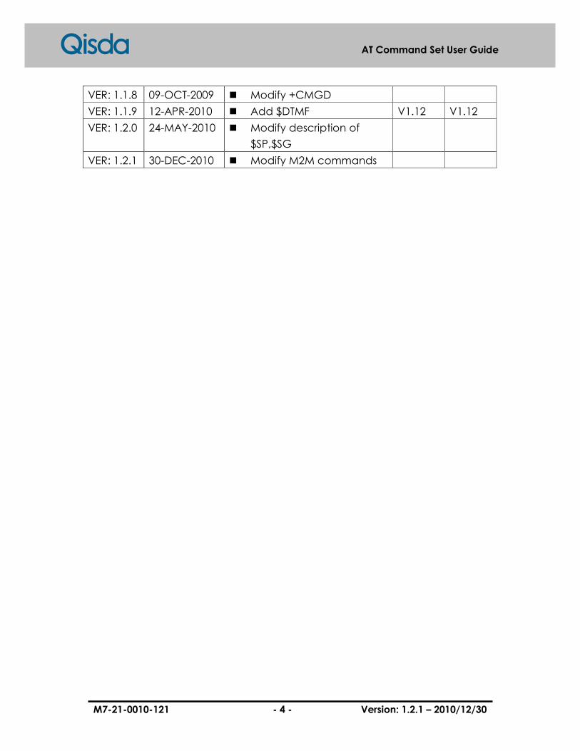
VER: 1.1.8 09-OCT-2009 � Modify +CMGD
VER: 1.1.9 12-APR-2010 � Add $DTMF V1.12 V1.12
VER: 1.2.0 24-MAY-2010 � Modify description of
$SP,$SG
VER: 1.2.1 30-DEC-2010 � Modify M2M commands
M7-21-0010-121 - 5 - Version: 1.2.1 – 2010/12/30
AT Command Set User Guide
NOTE
There are some “T.xx” (eg: 8.4.3/T.30) mentioned in this document. For more
information, please refer to “http://www.itu.int/rec/T-REC-T/e”.
M7-21-0010-121 - 6 - Version: 1.2.1 – 2010/12/30
AT Command Set User Guide
Contents
1 INTRODUCTION ......................................................................................................................................13
1.1 INTRODUCTION TO INTERFACE BETWEEN TE AND MS .........................................................................13
1.1.1 Explanation ....................................................................................................................................13
1.1.2 Getting started................................................................................................................................13
1.1.3 Syntax description ..........................................................................................................................13
1.1.4 AT command syntax........................................................................................................................14
1.1.5 AT response syntax .........................................................................................................................15
1.2 DOCUMENT CONVENTIONS ..................................................................................................................16
1.2.1 Parameter type ...............................................................................................................................16
1.2.2 Default value ..................................................................................................................................16
2 GENERAL COMMANDS .........................................................................................................................17
2.1 +CGMI: REQUEST MANUFACTURER IDENTIFICATION ..........................................................................17
2.2 +CGMM: REQUEST MODEL IDENTIFICATION .......................................................................................18
2.3 +CGMR: REQUEST REVISION IDENTIFICATION ....................................................................................19
2.4 +CGSN: REQUEST PRODUCT SERIAL NUMBER IDENTIFICATION ...........................................................20
2.5 +CSCS: SELECT TE CHARACTER SET ..................................................................................................21
2.6 +CIMI: REQUEST INTERNATIONAL MOBILE SUBSCRIBER IDENTITY......................................................23
2.7 +CMUX: MULTIPLEXING MODE ..........................................................................................................24
2.8 +WS46: SELECT WIRELESS NETWORK..................................................................................................29
2.9 A/: REPEATING A COMMAND LINE ........................................................................................................30
2.10 Z: RESET TO DEFAULT CONFIGURATION................................................................................................31
2.11 &F: SET TO FACTORY-DEFINED CONFIGURATION ..................................................................................32
2.12 I: REQUEST IDENTIFICATION INFORMATION ..........................................................................................33
2.13 +GMI: REQUEST MANUFACTURER IDENTIFICATION .............................................................................34
2.14 +GMM: REQUEST MODEL IDENTIFICATION..........................................................................................35
2.15 +GMR: REQUEST REVISION IDENTIFICATION .......................................................................................36
2.16 +GSN: REQUEST PRODUCT SERIAL NUMBER IDENTIFICATION ..............................................................37
2.17 +GCAP: REQUEST COMPLETE CAPABILITIES LIST ................................................................................38
2.18 S3: COMMAND LINE TERMINATION CHARACTER ..................................................................................39
2.19 S4: RESPONSE FORMATTING CHARACTER.............................................................................................40
2.20 S5: COMMAND LINE EDITING CHARACTER ...........................................................................................41
2.21 E: COMMAND ECHO .............................................................................................................................42

M7-21-0010-121 - 7 - Version: 1.2.1 – 2010/12/30
AT Command Set User Guide
2.22 Q: RESULT CODE SUPPRESSION ............................................................................................................43
2.23 V: DCE RESPONSE FORMAT..................................................................................................................44
2.24 X: RESULT CODE SELECTION AND CALL PROGRESS MONITORING CONTROL..........................................45
2.25 &C: CIRCUIT 109 (RECEIVED LINE SIGNAL DETECTOR) BEHAVIOR.......................................................46
2.26 &D: CIRCUIT 108 (DATA TERMINAL READY) BEHAVIOR .......................................................................47
2.27 +IPR: FIXED DTE RATE .......................................................................................................................48
2.28 +ICF: DTE-DCE CHARACTER FRAMING..............................................................................................50
2.29 +IFC: DTE-DCE LOCAL FLOW CONTROL ............................................................................................52
2.30 +ILRR: DTE-DCE LOCAL RATE REPORTING ........................................................................................54
2.31 +DR: DATA COMPRESSION REPORTING.................................................................................................56
2.32 $TIME: RTC TIME.............................................................................................................................58
2.33 $DATE: RTC DATE............................................................................................................................59
3 CALL CONTROL COMMANDS.............................................................................................................60
3.1 +CSTA: SELECT TYPE OF ADDRESS.....................................................................................................60
3.2 +CMOD: CALL MODE .........................................................................................................................61
3.3 +CHUP: HANG UP CALL ......................................................................................................................62
3.4 +CBST: SELECT BEARER SERVICE TYPE...............................................................................................63
3.5 +CRLP: RADIO LINK PROTOCOL ..........................................................................................................65
3.6 +CR: SERVICE REPORTING CONTROL ...................................................................................................66
3.7 +CRC: CELLULAR RESULT CODES........................................................................................................67
3.8 +CSNS: SINGLE NUMBERING SCHEME.................................................................................................69
3.9 D: DIAL ...............................................................................................................................................70
3.10 W: WAIT FOR DIAL TONE ......................................................................................................................72
3.11 T: SELECT TONE DIALING (DIAL MODIFIER) ..........................................................................................73
3.12 P: SELECT PULSE DIALING (DIAL MODIFIER).........................................................................................74
3.13 A: ANSWER ..........................................................................................................................................75
3.14 H: HOOK CONTROL ..............................................................................................................................76
3.15 S0: AUTOMATIC ANSWER .....................................................................................................................77
3.16 L: MONITOR SPEAKER LOUDNESS ........................................................................................................78
3.17 +++: ESCAPE FROM DATA MODE...........................................................................................................79
3.18 O: RETURN TO DATA MODE ..................................................................................................................80
3.19 %CPI: CALL PROGRESS INFORMATION.................................................................................................81
4 NETWORK SERVICE RELATED COMMANDS .................................................................................85
4.1 +CNUM: SUBSCRIBER NUMBER ..........................................................................................................85
4.2 +CREG: NETWORK REGISTRATION......................................................................................................86

M7-21-0010-121 - 8 - Version: 1.2.1 – 2010/12/30
AT Command Set User Guide
4.3 +COPS: OPERATOR SELECTION ...........................................................................................................88
4.4 +CLCK: FACILITY LOCK .....................................................................................................................90
4.5 +CPWD: CHANGE PASSWORD .............................................................................................................92
4.6 +CLIP: CALLING LINE IDENTIFICATION PRESENTATION .......................................................................93
4.7 +CLIR: CALL LINE IDENTIFICATION RESTRICTION ...............................................................................95
4.8 +COLP: CONNECTION LINE IDENTIFICATION PRESENTATION ...............................................................96
4.9 +CCUG: CLOSED USER GROUP............................................................................................................98
4.10 +CCFC: CALL FORWARDING SERVICE..................................................................................................99
4.11 +CCWA: CALL WAITING SERVICE ......................................................................................................101
4.12 +CHLD: CALL RELATED SUPPLEMENTARY SERVICES .........................................................................103
4.13 +CUSD: UNSTRUCTURED SUPPLEMENTARY SERVICE DATA ...............................................................104
4.14 +CAOC: ADVICE OF CHARGE ............................................................................................................105
4.15 +CSSN: SUPPLEMENTARY SERVICE NOTIFICATIONS ...........................................................................106
4.16 +CPOL: PREFERRED PLMN LIST ......................................................................................................108
4.17 +CLCC: LIST CURRENT CALLS ..........................................................................................................110
4.18 +COPN: READ OPERATOR NAMES .....................................................................................................112
4.19 $GNC: GET NEIGHBOR CELLS............................................................................................................113
4.20 %BAND: DYNAMIC MULTIBAND.......................................................................................................114
4.21 %CREG: NETWORK EXTENDED REGISTRATION STATUS.....................................................................115
5 MOBILE EQUIPMENT CONTROL AND STATUS COMMANDS...................................................116
5.1 +CPAS: PHONE ACTIVITY STATUS ......................................................................................................116
5.2 +CFUN: SET PHONE FUNCTIONALITY ................................................................................................117
5.3 $SRN: FACILITY STATUS NOTIFICATION .............................................................................................118
5.4 +CPIN: ENTER PIN ...........................................................................................................................119
5.5 +CSQ: SIGNAL QUALITY....................................................................................................................121
5.6 +CRSM: RESTRICTED SIM ACCESS ...................................................................................................122
5.7 +CLVL: LOUDSPEAKER VOLUME LEVEL............................................................................................124
5.8 +CMUT: MUTE .................................................................................................................................125
5.9 +CACM: ACCUMULATED CALL METER..............................................................................................126
5.10 +CAMM: ACCUMULATED CALL METER MAXIMUM............................................................................127
5.11 +CPUC: PRICE PER UNIT AND CURRENCY TABLE ...............................................................................128
5.12 +CCWE: CALL METER MAXIMUM EVENT .........................................................................................129
5.13 +CSVM: SET VOICE MAIL NUMBER .................................................................................................130
5.14 +CLAC: LIST ALL AVAILABLE AT COMMANDS ...................................................................................131
5.15 %PVRF: GET PIN1, PIN2, PUK1, PUK2 REMAINING NUMBER ........................................................132
5.16 +VTS: DTMF AND TONE GENERATION ..............................................................................................133

M7-21-0010-121 - 9 - Version: 1.2.1 – 2010/12/30
AT Command Set User Guide
5.17 +WDTMF: PLAY DTMF TONE ..........................................................................................................134
5.18 +VGR: RECEIVE GAIN SELECTION .....................................................................................................135
5.19 +VGT: TRANSMIT GAIN SELECTION ...................................................................................................136
5.20 $POWEROFF: POWER OFF ...............................................................................................................137
5.21 $CSQ: PERIODIC SIGNAL QUALITY REPORT ......................................................................................138
5.22 $SP: CONTROL AUDIO PATH ...............................................................................................................139
5.23 $SG: CONTROL AUDIO GAIN ..............................................................................................................140
5.24 $SAMP: CONTROL AUDIO AMPLIFICATION ........................................................................................142
5.25 $TRING: SET DURATION TO CLIP DATA ON INCOMING CALL...............................................................143
5.26 +GDT: PLAY A CALL TONE .................................................................................................................144
5.27 $NOSLEEP: DISABLE DEEP SLEEP MODE.........................................................................................145
5.28 $CSSL: PLAY TONE ON SPEAKER ......................................................................................................146
5.29 $GLED: GREEN LED SETTING..........................................................................................................147
5.30 $DTMF: STRING DTMF AND TONE GENERATION...............................................................................148
6 PHONEBOOK COMMANDS.................................................................................................................149
6.1 +CPBS: SELECT PHONEBOOK MEMORY STORAGE ..............................................................................149
6.2 +CPBR: READ PHONEBOOK ENTRIES.................................................................................................151
6.3 +CPBF: FIND PHONEBOOK ENTRIES ..................................................................................................153
6.4 +CPBW: WRITE PHONEBOOK ENTRY.................................................................................................155
6.5 $SMRC: SIM INDEX MANUALLY UPDATE..........................................................................................156
7 SHORT MESSAGES COMMANDS ......................................................................................................157
7.1 +CSMS: SELECT MESSAGE SERVICE ..................................................................................................157
7.2 +CPMS: PREFERRED MESSAGE STORAGE ..........................................................................................159
7.3 +CMGF: MESSAGE FORMAT..............................................................................................................161
7.4 +CSCA: SERVICE CENTRE ADDRESS ..................................................................................................162
7.5 +CSMP: TEXT MODE PARAMETERS ...................................................................................................163
7.6 +CSDH: SHOW TEXT MODE PARAMETERS .........................................................................................165
7.7 +CSCB: SELECT CELL BROADCAST MESSAGE TYPES .........................................................................166
7.8 +CSAS: SAVE SETTINGS ....................................................................................................................168
7.9 +CRES: RESTORE SETTINGS ..............................................................................................................169
7.10 +CNMI: NEW MESSAGE INDICATIONS TO TE .....................................................................................170
7.11 +CMGL: LIST MESSAGES ..................................................................................................................173
7.12 +CMGD: DELETE MESSAGE ..............................................................................................................175
7.13 +CMGC: SEND COMMAND ................................................................................................................176
7.14 +CMGR: READ MESSAGE..................................................................................................................178

M7-21-0010-121 - 10 - Version: 1.2.1 – 2010/12/30
AT Command Set User Guide
7.15 +CNMA: NEW MESSAGE ACKNOWLEDGEMENT TO ME/TA...............................................................181
7.16 +CMGS: SEND SHORT MESSAGE........................................................................................................182
7.17 +CMSS: SEND SHORT MESSAGE FROM THE STORAGE ........................................................................183
7.18 +CMGW: SEND WRITE MESSAGE TO MEMORY ................................................................................184
8 FAX CONTROL.......................................................................................................................................185
8.1 +FDT: SEND A PAGE...........................................................................................................................185
8.2 +FDR: RECEIVE A PAGE .....................................................................................................................186
8.3 +FKS: TERMINATE A SESSION, ORDERLY FAX ABORT..........................................................................188
8.4 +FIP: INITIALIZE SERVICE CLASS 2 PARAMETERS ...............................................................................189
8.5 DCE RESPONSES, +FCS: REPORT DCS FRAME INFORMATION ...........................................................190
8.6 DCE RESPONSES, +FIS: REPORT REMOTE CAPABILITIES, DIS............................................................192
8.7 DCE RESPONSES, +FPI: REPORT REMOTE ID,CIG .............................................................................193
8.8 DCE RESPONSES, +FNC: REPORT NSC FRAME..................................................................................194
8.9 DCE RESPONSES, +FNF: REPORT NSF FRAME ..................................................................................195
8.10 DCE RESPONSES, +FNS: REPORT NSS FRAME ..................................................................................196
8.11 DCE RESPONSES, +FPW: REPORT PASSWORD....................................................................................197
8.12 DCE RESPONSES, +FSA: REPORT DESTINATION SUBADDRESS ...........................................................198
8.13 DCE RESPONSES, +FPA: REPORT POLLING ADDRESS .........................................................................199
8.14 DCE RESPONSES, +FPS: REPORT T.30 PHASE C PAGE RECEPTION......................................................200
8.15 DCE RESPONSES, +FHS: CALL TERMINATION STATUS .......................................................................202
8.16 +FCLASS: SERVICE CLASS IDENTIFICATION AND CONTROL ..............................................................204
8.17 +FCC: DCE CAPABILITIES PARAMETER .............................................................................................205
8.18 +FIS: CURRENT SESSION PARAMETER................................................................................................206
8.19 +FCS: CURRENT SESSION RESULTS (FAX CLASS 2.0)..........................................................................207
8.20 +FLI: LOCAL FACSIMILE STATION ID STRING, TSI/CSI ......................................................................208
8.21 +FPI: LOCAL FACSIMILE STATION ID, CIG(LOCAL POLLING ID) ........................................................209
8.22 +FNS: PASS-THROUGH NON-STANDARD NEGOTIATION BYTE STRING .................................................210
8.23 +FLP: INDICATE DOCUMENT AVAILABLE FOR POLLING ......................................................................211
8.24 +FSP: REQUEST TO POLL ...................................................................................................................212
8.25 +FCR: CAPABILITY TO RECEIVE.........................................................................................................213
8.26 +FBU: HDLC FRAME REPORTING ENABLE ........................................................................................214
8.27 +FNR: NEGOTIATION REPORTING ENABLE.........................................................................................215
8.28 +FAP: ADDRESS & POLLING CAPABILITIES ........................................................................................216
8.29 +FSA: ADDRESS & POLLING FRAME/SUBADDRESS ............................................................................217
8.30 +FPA: ADDRESS & POLLING FRAME/POLLING ADDRESS.....................................................................218
8.31 +FPW: ADDRESS & POLLING FRAME/PASSWORD ...............................................................................219

M7-21-0010-121 - 11 - Version: 1.2.1 – 2010/12/30
AT Command Set User Guide
8.32 +FIE: PROCEDURE INTERRUPT ENABLE .............................................................................................220
8.33 +FPS: PAGE STATUS ...........................................................................................................................221
8.34 +FCQ: COPY QUALITY CHECKING......................................................................................................223
8.35 +FRQ: RECEIVE QUALITY CHECKING.................................................................................................225
8.36 +FCT: DTE PHASE C RESPONSE TIMEOUT .........................................................................................226
8.37 +FHS : CALL TERMINATION STATUS ...................................................................................................227
8.38 +FMS: MINIMUM PHASE C SPEED ......................................................................................................228
8.39 +FIT: INACTIVITY TIMEOUT ...............................................................................................................229
8.40 +FBS: REPORT BUFFER SIZE ..............................................................................................................230
8.41 +FBO: DATA BIT ORDER ....................................................................................................................231
8.42 +FEA: PHASE C RECEIVED EOL ALIGNMENT ....................................................................................232
8.43 +FFC: IMAGE DATA FORMAT CONVERSION.........................................................................................233
8.44 +FLO: FLOW CONTROL......................................................................................................................234
9 GPRS RELATED COMMANDS ............................................................................................................235
9.1 +CGDCONT: DEFINE PDP CONTEXT ................................................................................................235
9.2 +CGQREQ: QUALITY OF SERVICE PROFILE.......................................................................................237
9.3 +CGQMIN: QUALITY OF SERVICE PROFILE (MINIMUM ACCEPTABLE) ...............................................240
9.4 +CGATT: GPRS ATTACH OR DETACH ................................................................................................243
9.5 +CGACT: PDP CONTEXT ACTIVATE OR DEACTIVATE .........................................................................244
9.6 +CGDATA: ENTER DATA STATE.........................................................................................................246
9.7 +CGPADDR: SHOW PDP ADDRESS ...................................................................................................248
9.8 +CGAUTO: AUTOMATIC RESPONSE TO A NETWORK REQUEST FOR PDP CONTEXT ACTIVATION.........250
9.9 +CGANS: MANUAL RESPONSE TO A NETWORK REQUEST FOR PDP CONTEXT ACTIVATION ................252
9.10 + CGCLASS: GPRS MOBILE STATION CLASS ....................................................................................255
9.11 + CGEREP: GPRS EVENT REPORTING...............................................................................................256
9.12 + CGREG: GPRS NETWORK REGISTRATION STATUS..........................................................................258
9.13 + CGSMS: SELECT SERVICE FOR MO SMS MESSAGES ......................................................................260
9.14 D: REQUEST GPRS SERVICE ..............................................................................................................261
9.15 S0: AUTOMATIC RESPONSE TO A NETWORK REQUEST FOR PDP CONTEXT ACTIVATION .......................263
9.16 A: MANUAL ACCEPTANCE OF A NETWORK REQUEST...........................................................................264
9.17 H: MANUAL REJECTION OF A NETWORK REQUEST FOR PDP CONTEXT ACTIVATION ............................265
9.18 %CGAATT: GPRS AUTOMATIC ATTACH MODE .................................................................................266
9.19 %CGPPP: PPP AUTHENTICATION PROTOCOL.....................................................................................267
9.20 %PPP: PREPARE CIRCUIT-SWITCHED DATA CALL ..............................................................................268
9.21 %CGREG: GPRS NETWORK EXTENDED REGISTRATION STATUS........................................................269
10 M2M COMMANDS .................................................................................................................................271

M7-21-0010-121 - 12 - Version: 1.2.1 – 2010/12/30
AT Command Set User Guide
11 SIM APPLICATION TOOLKIT COMMANDS ...................................................................................272
11.1 %SATM: SET SAT COMMAND/RESPONSE FORMAT ............................................................................272
11.2 %SATC: CONFIGURATION FOR SIM APPLICATION TOOLKIT...............................................................274
11.3 %SATE: SEND SAT ENVELOP COMMAND..........................................................................................280
11.4 %SATR: SEND SAT RESPONSE ..........................................................................................................282
11.5 %SATT: TERMINATE SAT COMMAND OR SESSION .............................................................................285
12 ERROR REPORT COMMANDS AND ERROR CODE......................................................................286
12.1 +CMEE: REPORT MOBILE EQUIPMENT ERROR ...................................................................................286
12.2 +CME ERROR: ME ERROR RESULT CODE ........................................................................................287
12.3 +CMS ERROR: MESSAGE SERVICE FAILURE RESULT CODE ...............................................................291
12.4 +CEER: EXTENDED ERROR REPORT...................................................................................................293
12.5 +CEER EXTENDED ERROR RESULT CODE ...........................................................................................294
12.6 +EXT ERROR: EXTENDED ERROR RESULT CODE ..............................................................................296

M7-21-0010-121 - 13 - Version: 1.2.1 – 2010/12/30
AT Command Set User Guide
1 Introduction
1.1 Introduction to Interface between TE and MS
In order to communicate each other between TE and MS, we must use AT commands.
Figure 1.1 illustrates the interface. In addition, we will describe about SIM, list
management, mobility management, call control, supplementary service, short
message, cell broadcast, base-band and the other service in next section.
Figure 1.1
1.1.1 Explanation
Command Possible response(s)
ME Mobile equipment
MS Mobile station. Basically, a mobile station is mobile equipment with a SIM card.
TE Terminal Equipment that is the same as the controller in this case.
1.1.2 Getting started
For testing AT commands, the MS can be connected to any computer environment,
as long as it has a V.24/V.28 serial interface. The commands can be issued with, for
example, HyperTerminal in Microsoft Windows or other emulator programs.
1.1.3 Syntax description
This section gives a brief description of the syntax used for the command set. The MS
may echo characters which is received, depending on the setting of the command E.
As a default, echo is enabled. In addition, the received characters are echoed by
the same rate, parity, and format.
The character defined by parameter S5 (default, BS, IRA 8) is interpreted to be a
request from the TE for deleting the previous character.
TE MS
AT COMMAND
M7-21-0010-121 - 14 - Version: 1.2.1 – 2010/12/30
AT Command Set User Guide
Command Possible response(s)
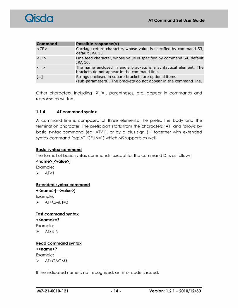
<CR> Carriage return character, whose value is specified by command S3, default IRA 13.
<LF> Line feed character, whose value is specified by command S4, default IRA 10.
<…> The name enclosed in angle brackets is a syntactical element. The brackets do not appear in the command line.
[…] Strings enclosed in square brackets are optional items (sub-parameters). The brackets do not appear in the command line.
Other characters, including ‘?’,’=’, parentheses, etc, appear in commands and
response as written.
1.1.4 AT command syntax
A command line is composed of three elements: the prefix, the body and the
termination character. The prefix part starts from the characters ‘AT’ and follows by
basic syntax command (eg: ATV1), or by a plus sign (+) together with extended
syntax command (eg: AT+CFUN=1) which MS supports as well.
Basic syntax command
The format of basic syntax commands, except for the command D, is as follows:
<name>[<value>]
Example:
� ATV1
Extended syntax command
+<name>[=<value>]
Example:
� AT+CMUT=0
Test command syntax
+<name>=?
Example:
� ATS3=?
Read command syntax
+<name>?
Example:
� AT+CACM?
If the indicated name is not recognized, an Error code is issued.

M7-21-0010-121 - 15 - Version: 1.2.1 – 2010/12/30
AT Command Set User Guide
1.1.5 AT response syntax
The <response> can be:
� Basic format result code
� OK
� Extended syntax result code, prefixed with a plus sign (+)
� +<name>: <value>
The result codes will be separated by commas if it includes several values. The
<value> followed by the colon is separated by a space. It is also possible that result
codes have no value. Unlike basic format result codes, extended syntax result codes
have no numeric equivalent, and are always issued in alphabetic form.
There are two types of result code responses:
Final result code
A final result code indicates to the TE that execution of the command is completed
and another command may be issued.
If you type an implemented AT command, you should get the result code OK.
If you type an AT command which is not ready for users, or the parameter or syntax
you provide is wrong, you will get the result code ERROR or something else, for
example, +CME ERROR followed by an error code.
Unsolicited result code
Unsolicited result codes, such as RING, indicate that the occurrence caused by an
event is not directly associated with a command which is issued from TE.
M7-21-0010-121 - 16 - Version: 1.2.1 – 2010/12/30
AT Command Set User Guide
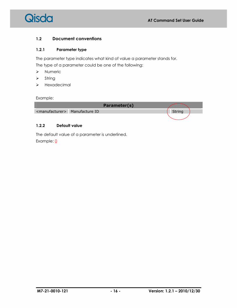
1.2 Document conventions
1.2.1 Parameter type
The parameter type indicates what kind of value a parameter stands for.
The type of a parameter could be one of the following:
� Numeric
� String
� Hexadecimal
Example:
Parameter(s)
<manufacturer> Manufacture ID String
1.2.2 Default value
The default value of a parameter is underlined.
Example: 0

M7-21-0010-121 - 17 - Version: 1.2.1 – 2010/12/30
AT Command Set User Guide
2 General Commands
2.1 +CGMI: Request manufacturer identification
Read the model’s manufacturer ID.
Syntax
AT+CGMI
Response(s) � <manufacturer> OK
� +CME ERROR: <err>
Parameter(s)
<manufacturer> Manufacture ID, Qisda. String
Example(s)
Request manufacturer identification
AT+CGMI Qisda OK
M7-21-0010-121 - 18 - Version: 1.2.1 – 2010/12/30
AT Command Set User Guide
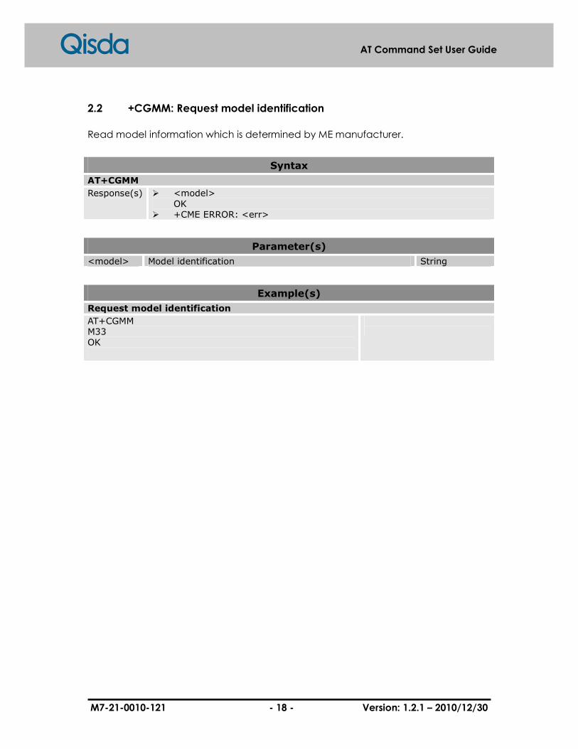
2.2 +CGMM: Request model identification
Read model information which is determined by ME manufacturer.
Syntax
AT+CGMM
Response(s) � <model> OK
� +CME ERROR: <err>
Parameter(s)
<model> Model identification String
Example(s)
Request model identification
AT+CGMM M33 OK

M7-21-0010-121 - 19 - Version: 1.2.1 – 2010/12/30
AT Command Set User Guide
2.3 +CGMR: Request revision identification
Read revision of ME. It includes software and hardware revision.
Syntax
AT+CGMR
Response(s) � <SW revision> <HW revision> <build date> <build time> OK
� +CME ERROR: <err>
Parameter(s)
<SW revision> Software version number with m.nn format, where the m is the major number, n is the minor number
String
<HW revision> Hardware version number, use the same format as software version.
String
<build date> Software build date with MM DD YYYY format String
<build time> Software build time with h:m:s format String
Example(s)
Request revision identification
AT+CGMR SW ver: 1.00 HW ver: 1.00 Build Date: Dec 13 2007 Build Time: 09:15:11 OK

M7-21-0010-121 - 20 - Version: 1.2.1 – 2010/12/30
AT Command Set User Guide
2.4 +CGSN: Request product serial number identification
Read serial number identification which is determined by ME manufacturer.
Syntax
AT+CGSN
Response(s) � <sn> OK
� +CME ERROR: <err>
Parameter(s)
<sn> Serial number String
Example(s)
Request product serial number identification
AT+CGSN 446019197507595 OK

M7-21-0010-121 - 21 - Version: 1.2.1 – 2010/12/30
AT Command Set User Guide
2.5 +CSCS: Select TE character set
Set command informs TA which character set “<chset>” is used by the TE. TA is then
able to convert character strings correctly between TE and ME character sets.
When TA-TE interface is set to 8-bit operation and its TE alphabet is 7 bit, the highest bit
shall be set to zero.
Read command returns the current setting and Test command displays conversion
schemes implemented in the TA.
Syntax
AT+CSCS=[<chset>]
Response(s) � OK � +CME ERROR: <err>
AT+CSCS?
Response(s) � +CSCS: <chset> OK
� +CME ERROR: <err>
AT+CSCS=?
Response(s) � +CSCS: (list of supported <chset>s) OK
Parameter(s)
<chset> Character set type which is used by TE String
“IRA” International reference alphabet.
“HEX” Character strings consist only of hexadecimal numbers from 00 to FF;e.g. “032FE6” equals three 8-bit characters with decimal values 3,47 and 230;no conversions to the original ME character set shall be done.
“GSM” GSM alphabet.
“UCS2” 16-bit universal multiple-octet coded character set; UCS2 character strings are converted to hexadecimal numbers from 0000 to FFFF. ; e.g. “004100620063” equals three 16-bit characters with decimal values 65,98 and 99.
“8859-1” ISO 8859 Latin 1 character set.
“PCCP437” PC character set Code Page 437.
“PCDN” PC Danish/Norwegian character set.
M7-21-0010-121 - 22 - Version: 1.2.1 – 2010/12/30
AT Command Set User Guide
Example(s)
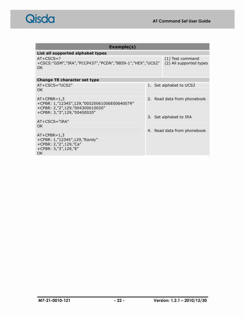
List all supported alphabet types
AT+CSCS=? +CSCS:”GSM”,”IRA”,”PCCP437”,”PCDN”,”8859-1”,”HEX”,”UCS2” OK
(1) Test command (2) All supported types
Change TE character set type
AT+CSCS=”UCS2” OK AT+CPBR=1,3 +CPBR: 1,”12345”,129,”00520061006E00640079” +CPBR: 2,”2”,129,”004300610020” +CPBR: 3,”3”,129,”00450020” AT+CSCS=”IRA” OK AT+CPBR=1,3 +CPBR: 1,”12345”,129,”Randy” +CPBR: 2,”2”,129,”Ca” +CPBR: 3,”3”,129,”E” OK
1. Set alphabet to UCS2 2. Read data from phonebook 3. Set alphabet to IRA 4. Read data from phonebook

M7-21-0010-121 - 23 - Version: 1.2.1 – 2010/12/30
AT Command Set User Guide
2.6 +CIMI: Request international mobile subscriber identity
Execution command causes the TA to return <IMSI>, which is intended to permit the
TE for identifying the individual SIM that is attached to ME.
Syntax
AT+CIMI
Response(s) � <IMSI> OK
� +CME ERROR: <err>
Parameter(s)
<IMSI> IMSI number String
Example(s)
Request international mobile subscriber identity
AT+CIMI 466880100493652 OK

M7-21-0010-121 - 24 - Version: 1.2.1 – 2010/12/30
AT Command Set User Guide
2.7 +CMUX: Multiplexing mode
This command is used to enable/disable the GSM 07.10 multiplexing protocol control
channel. Refer to subclause 9.2 for possible <err> values. The AT commands sets
parameters for the Control Channel. If the parameters are left out, the default value is
used.
Read command returns the current mode and the settings.
Test command returns the supported modes and parameters.
It is recommended that the ME/TA/TE should autobaud to the +CMUX command up
to and including an interface speed of 9600 bits/s.
The OK or +CME ERROR: <err> response is returned at the speed of the +CMUX
command prior to entering <mode>.
It is recommended that whenever the multiplexer control channel is released the
ME/TA/TE should assume an interface rate of up to and including 9600 bits/s for auto
bauding purposes irrespective of any previous higher speed having been selected.
If a +CMUX command is issued whilst in any multiplexer mode then that +CMUX
command shall be ignored and the ME/TA shall return an +CME ERROR: <err>
response.
Syntax
AT+CMUX=<mode>[,<subset>[,<port_speed>[,<N1>[,<T1>[,<N2>[,<T2>[,<T3>[,<k>]]]]]]]]
Response(s) � +CME ERROR: <err>
AT+CMUX?
Response(s) � OK
AT+CMUX= ?
Response(s) � +CMUX: (list of supported <mode>s), (list of supported <subset>s), (list of supported <port_speed>s), (list of supported <N1>s), (list of supported <T1>s), (list of supported <N2>s), (list of supported <T2>s), (list of supported <T3>s), (list of supported <k>s)
Parameter(s)
<mode> Multiplexer Transparency Mechanism Numeric
0 Basic Option
M7-21-0010-121 - 25 - Version: 1.2.1 – 2010/12/30
AT Command Set User Guide
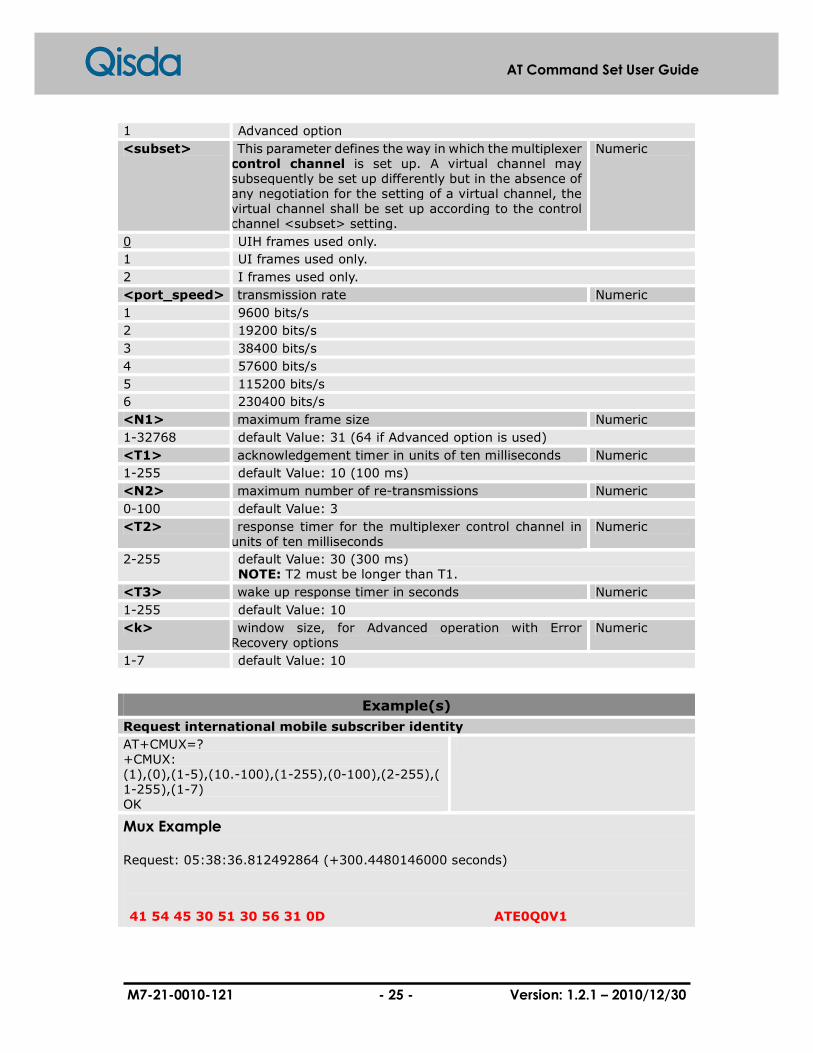
1 Advanced option
<subset> This parameter defines the way in which the multiplexer control channel is set up. A virtual channel may subsequently be set up differently but in the absence of any negotiation for the setting of a virtual channel, the virtual channel shall be set up according to the control channel <subset> setting.
Numeric
0 UIH frames used only.
1 UI frames used only.
2 I frames used only.
<port_speed> transmission rate Numeric
1 9600 bits/s
2 19200 bits/s
3 38400 bits/s
4 57600 bits/s
5 115200 bits/s
6 230400 bits/s
<N1> maximum frame size Numeric
1-32768 default Value: 31 (64 if Advanced option is used)
<T1> acknowledgement timer in units of ten milliseconds Numeric
1-255 default Value: 10 (100 ms)
<N2> maximum number of re-transmissions Numeric
0-100 default Value: 3
<T2> response timer for the multiplexer control channel in units of ten milliseconds
Numeric
2-255 default Value: 30 (300 ms) NOTE: T2 must be longer than T1.
<T3> wake up response timer in seconds Numeric
1-255 default Value: 10
<k> window size, for Advanced operation with Error Recovery options
Numeric
1-7 default Value: 10
Example(s)
Request international mobile subscriber identity
AT+CMUX=? +CMUX: (1),(0),(1-5),(10.-100),(1-255),(0-100),(2-255),(1-255),(1-7) OK
Mux Example
Request: 05:38:36.812492864 (+300.4480146000 seconds)
41 54 45 30 51 30 56 31 0D ATE0Q0V1

M7-21-0010-121 - 26 - Version: 1.2.1 – 2010/12/30
AT Command Set User Guide
Normal AT command mode at initial
Answer: 05:38:36.822507464 (+0.0100146000 seconds)
0D 0A 4F 4B 0D 0A ..OK..
The response of ATE0Q0V1
Request: 05:38:37.583617064 (+0.5908614000 seconds)
41 54 2B 43 4D 55 58 3D 31 2C 30 2C 35 0D AT+CMUX=1,0,5.
Mux mode enable command Advanced without error recovery
Answer: 05:38:37.593631664 (+0.0100146000 seconds)
0D 0A 4F 4B 0D 0A ..OK..
The response of MUX mode command
From now on all command and information should be encapsulated with HDLC format
Request: 05:38:38.394799664 (+0.8011680000 seconds)
7E 03 3F FC 7E ~.?ü~
First SABM packet to start DLC 0 (that is , disconnected mode)
Answer: 05:38:38.404814264 (+0.0100146000 seconds)
7E 03 73 85 7E ~.s…~
The ACK of first SABM
After the response packet is send , the control channel ,DLC 0 is established
Request: 05:38:38.655179264 (+0.2503650000 seconds)
M7-21-0010-121 - 27 - Version: 1.2.1 – 2010/12/30
AT Command Set User Guide
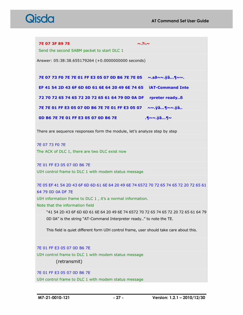
7E 07 3F 89 7E ~.?‰~
Send the second SABM packet to start DLC 1
Answer: 05:38:38.655179264 (+0.0000000000 seconds)
7E 07 73 F0 7E 7E 01 FF E3 05 07 0D B6 7E 7E 05 ~.sð~~.ÿã...¶~~.
EF 41 54 2D 43 6F 6D 6D 61 6E 64 20 49 6E 74 65 ïAT-Command Inte
72 70 72 65 74 65 72 20 72 65 61 64 79 0D 0A DF rpreter ready..ß
7E 7E 01 FF E3 05 07 0D B6 7E 7E 01 FF E3 05 07 ~~.ÿã...¶~~.ÿã..
0D B6 7E 7E 01 FF E3 05 07 0D B6 7E .¶~~.ÿã...¶~
There are sequence responses form the module, let’s analyze step by step
7E 07 73 F0 7E
The ACK of DLC 1, there are two DLC exist now
7E 01 FF E3 05 07 0D B6 7E
UIH control frame to DLC 1 with modem status message
7E 05 EF 41 54 2D 43 6F 6D 6D 61 6E 64 20 49 6E 74 6572 70 72 65 74 65 72 20 72 65 61
64 79 0D 0A DF 7E
UIH information frame to DLC 1 , it’s a normal information.
Note that the information field
“41 54 2D 43 6F 6D 6D 61 6E 64 20 49 6E 74 6572 70 72 65 74 65 72 20 72 65 61 64 79
0D 0A” is the string “AT-Command Interpreter ready..” to note the TE.
This field is quiet different form UIH control frame, user should take care about this.
7E 01 FF E3 05 07 0D B6 7E
UIH control frame to DLC 1 with modem status message
(retransmit)
7E 01 FF E3 05 07 0D B6 7E
UIH control frame to DLC 1 with modem status message

M7-21-0010-121 - 28 - Version: 1.2.1 – 2010/12/30
AT Command Set User Guide
(retarnsmit)
As you can see the TE do not response the UIH control frame at all. The
module just retransmit the frame until for N2 times. After retrying N2 times,
the module give up.

M7-21-0010-121 - 29 - Version: 1.2.1 – 2010/12/30
AT Command Set User Guide
2.8 +WS46: select wireless network
Set command will set WDS side stack <n> to be used by the TA. Read command
shows current setting and Test command displays side stacks implemented in the TA.
Syntax
AT+WS46=[<n>]
Response(s) � OK � +CME ERROR: <err>
AT+WS46?
Response(s) � +WS46: <n> OK
� +CME ERROR: <err>
AT+WS46=?
Response(s) � +WS46: (list of supported <n>s)] OK
� +CME ERROR: <err>
Parameter(s)
<n> Wireless network type Numeric
12 GSM digital cellular.
M7-21-0010-121 - 30 - Version: 1.2.1 – 2010/12/30
AT Command Set User Guide
2.9 A/: Repeating a command line
If the prefix "A/" or "a/" is received, the DCE will immediately execute the body of the
preceding command line once again. No editing is possible, and no termination
character is necessary. A command line may be repeated multiple times through this
mechanism, if it is requested. Responses from the repeated command line shall be
issued using the same parity and format as the original command line, and the same
rate of the "A/". If "A/" is received before completely executing any command line,
the preceding command line is assumed to be empty (that results in an OK result
code).
Syntax
A/
Response(s) � OK � +CME ERROR: <err>
M7-21-0010-121 - 31 - Version: 1.2.1 – 2010/12/30
AT Command Set User Guide
2.10 Z: Reset to default configuration
This command instructs the DCE to set all parameters to their factory default values
specified by the manufacturer. Moreover, the settings of hardware configuration
switches or non-volatile parameter storage (if it is implemented) may be took into
consideration as well. If the DCE is connected to the line, it will be disconnected and
will terminate any call in progress once ATZ command is executed.
All functions of the command shall be done completely before the DCE issues the
result code. The DTE should not include additional commands on the same
command line after the Z command; otherwise, these extra commands may be
ignored.
An OK result code for this command is issued using the same rate, parity, and format
as the DTE command line that contains the command, but the different new values
for parameters that affect the format of result codes (e.g. Q, V, S3, S4).
Syntax
ATZ[<N>]
Response(s) � OK � +CME ERROR: <err>
Parameter(s)
<N> Numeric
0 Reset to profile number 0

M7-21-0010-121 - 32 - Version: 1.2.1 – 2010/12/30
AT Command Set User Guide
2.11 &F: Set to factory-defined configuration
This command instructs the DCE to set all parameters to default values specified by
the manufacturer, which may take into consideration of hardware configuration
switches and other manufacturer-defined criteria.
An OK result code for this command is issued using the same rate, parity, and format
as the DTE command line that contains the command; however, the factory-defined
values is used for other parameters that affect the format of result codes (e.g. Q, V, S3,
S4). Besides, it is dependent upon other commands that may follow the same
command line.
Syntax
AT&F[<N>]
Response(s) � OK � +CME ERROR: <err>
Parameter(s)
<N> Parameter sets/shows the result code presentation status in the TA.
Numeric
0 Set parameters to factory defaults.
Other Reserved for manufactory proprietary use.

M7-21-0010-121 - 33 - Version: 1.2.1 – 2010/12/30
AT Command Set User Guide
2.12 I: Request identification information
This command causes the DCE to transmit one or more lines of information text,
determined by the manufacturer, follow by a final result code. <N> may be used
optionally to get specific information from the multiple types of identifying information,
specified by the manufacturer.
Syntax
ATI<N>
Response(s) � OK � +CME ERROR: <err>
Parameter(s)
<N> Type of identifying information Numeric
0-1

M7-21-0010-121 - 34 - Version: 1.2.1 – 2010/12/30
AT Command Set User Guide
2.13 +GMI: Request manufacturer identification
This command causes the DCE to transmit one or more lines of information text,
determined by the manufacturer, which is intended to permit the user of the DCE for
identifying the manufacturer. Typically, the text will consist of a single line that
contains the name of the manufacturer; nevertheless, manufacturers may tend to
provide more information (e.g. address, telephone number for customer service, etc.)
if there is a request.
About the response, the total number of characters, including line terminators, within
the information text returned for this command shall not exceed 2048 characters.
Note that the information text shall not contain the sequence “0 <CR>” or “OK<CR>”
for DTE to avoid false detection of the information text.
Syntax
AT+GMI
Response(s) � <Manufacturer> OK
� +CME ERROR: <err>
AT+GMI=?
Response(s) � OK � +CME ERROR: <err>
Parameter(s)
<Manufacturer> Manufacturer information String
Example(s)
Request manufacturer identification
AT+GMI Qisda OK
1. Ask manufacturer name

M7-21-0010-121 - 35 - Version: 1.2.1 – 2010/12/30
AT Command Set User Guide
2.14 +GMM: Request model identification
This command causes the DCE to transmit one or more lines of information text,
determined by the manufacturer, which is intended to permit the user of the DCE for
identifying the specific model of device. Typically, the text will consist of a single line
that contains the name of the product; nevertheless, manufacturers may tend to
provide any information which is requested.
About the response, the total number of characters, including line terminators, within
the information text returned for this command shall not exceed 2048 characters.
Note that the information text shall not contain the sequence “0 <CR>” or “OK<CR>”
for DTE to avoid false detection of the information text.
Syntax
AT+GMM
Response(s) � <Model name> OK
� +CME ERROR: <err>
AT+GMM=?
� OK � +CME ERROR: <err>
Parameter(s)
<Model name> Report information to identify the information of the device
String
Example(s)
Request model identification
AT+GMM M33 OK
1. Ask model id
M7-21-0010-121 - 36 - Version: 1.2.1 – 2010/12/30
AT Command Set User Guide
2.15 +GMR: Request revision identification
This command causes the DCE to transmit one or more lines of information text,
determined by the manufacturer, which is intended to permit the user of the DCE for
identifying the version, revision level or date, or other pertinent information of the
device. Typically, the text will consist of a single line that contains the version of the
product; nevertheless, manufacturers may tend to provide any information which is
requested.
About the response, the total number of characters, including line terminators, within
the information text returned for this command shall not exceed 2048 characters.
Note that the information text shall not contain the sequence “0 <CR>” or “OK<CR>”
for DTE to avoid false detection of the information text.
Syntax
AT+GMR
Response(s) � SW ver:<x.y> HW ver:<x.y> Build Date:mm dd yyyy Build Time:HH:MM:SS OK
� +CME ERROR: <err>
AT+GMR=?
� OK � +CME ERROR: <err>
Example(s)
Request revision identification
AT+GMR SW ver: 1.10 HW ver: 1.00 Build Date: Dec 13 2007 Build Time: 07:07:22 OK
1. Ask version number

M7-21-0010-121 - 37 - Version: 1.2.1 – 2010/12/30
AT Command Set User Guide
2.16 +GSN: Request product serial number identification
This command causes the DCE to transmit one or more lines of information text,
determined by the manufacturer, which is intended to permit the user of the DCE for
identifying the individual device. Typically, the text will consist of a single line that
contains a manufacturer represented by a alpha-numeric string; nevertheless,
manufacturers may tend to provide any information which is requested.
About the response, the total number of characters, including line terminators, within
the information text returned for this command shall not exceed 2048 characters.
Note that the information text shall not contain the sequence “0 <CR>” or “OK<CR>”
for DTE to avoid false detection of the information text.
Syntax
AT+GSN
Response(s) � <sn> OK
� +CME ERROR: <err>
AT+GSN=?
Response(s) � OK � +CME ERROR: <err>
Parameter(s)
<sn> IMEI of the telephone Numeric
Example(s)
Request product serial number identification
AT+GSN 004400003501234 OK
1. Request serial id

M7-21-0010-121 - 38 - Version: 1.2.1 – 2010/12/30
AT Command Set User Guide
2.17 +GCAP: Request complete capabilities list
This extended-format command causes the DCE to transmit one or more lines of
information text with a specific format. The content is a list displays additional
capabilities command +<name>s, which is intended to permit the user of the DCE for
identifying the overall capabilities of the DCE.
In particular, if the DCE implements a particular DCE control standard, which uses
Extended Syntax Commands and includes command(s) that indicate general
capabilities, the +<name>(s) of the those commands shall be reported to the DCE in
response to a +GCAP command. Examples can be seen from the following table.
Syntax
AT+GCAP
Response(s) � +GCAP:<name> OK
� +CME ERROR: <err>
Parameter(s)
<name> Report a list of capabilities String
Example(s)
Request complete capabilities list
AT+GCAP +GCAP: +CGSM,+FCLASS OK
1. Get capabilities list
M7-21-0010-121 - 39 - Version: 1.2.1 – 2010/12/30
AT Command Set User Guide
2.18 S3: Command line termination character
This S-parameter represents the decimal IA5 value of the character recognized by the
DCE from the DTE for terminating an incoming command line. It is also generated by
the DCE as part of the header, trailer, and terminator for result codes and information
text, along with the S4 parameter (see the description of the V parameter for usage).
The previous value of S3 is used to determine the command line termination
character for the entry of the command line which contains the S3 setting command.
However, the result code issued will base on the value of S3 set during the process of
the command line. For example, if S3 was previously set to 13 and the command line
“ATS3=30” is issued, the command line shall be terminated with a CR character (IA5
0/13), but the result code issued will use the character with the ordinal value 30 (IA5
2/14) in place of the CR.
Syntax
ATS3=<n>
Response(s) � OK � +CME ERROR: <err>
Parameter(s)
<n> Set command line termination character to this value. Numeric
0-13-127

M7-21-0010-121 - 40 - Version: 1.2.1 – 2010/12/30
AT Command Set User Guide
2.19 S4: Response formatting character
This S-parameter represents the decimal IA5 value of the character generated by the
DCE as part of the header, trailer, and terminator for result codes and information text,
along with the S3 parameter (see the description of the V parameter for usage).
If the value of S4 is changed in a command line, the result code issued will be base on
the new value of S4.
Syntax
ATS4=<n>
Response(s) � OK � +CME ERROR: <err>
Parameter(s)
<n> Set response formatting character to this value. Numeric
0-10-127
M7-21-0010-121 - 41 - Version: 1.2.1 – 2010/12/30
AT Command Set User Guide
2.20 S5: Command line editing character
This S-parameter represents the decimal IA5 value of the character recognized by the
DCE as a request for deleting this specific character from the command line
immediately.
Syntax
ATS5=<n>
Response(s) � OK � +CME ERROR: <err>
Parameter(s)
<n> Set command line editing character to this value. Numeric
0-8-127
M7-21-0010-121 - 42 - Version: 1.2.1 – 2010/12/30
AT Command Set User Guide
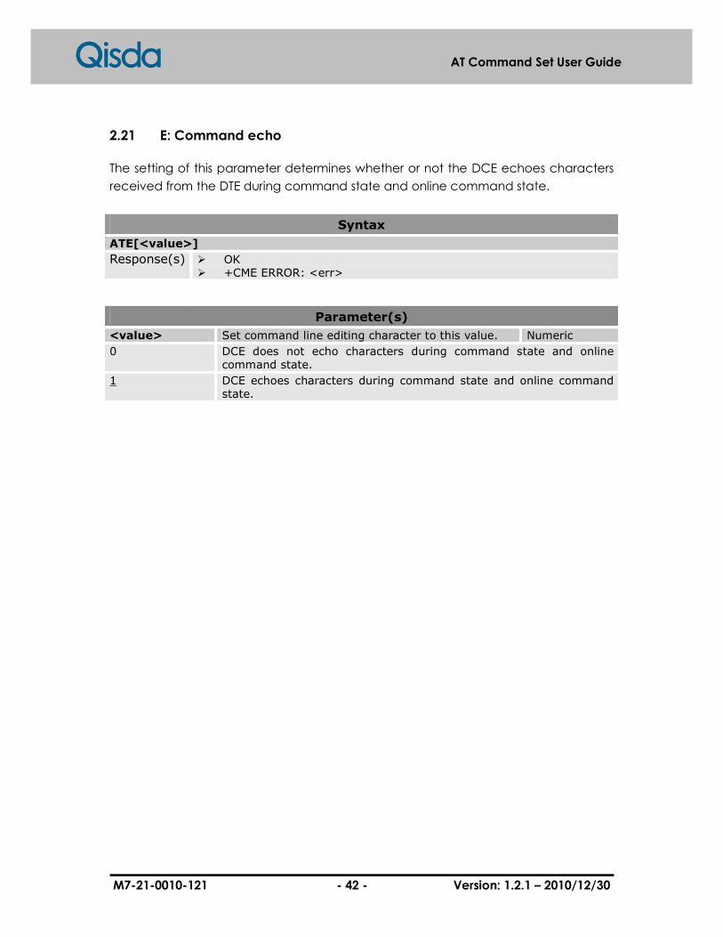
2.21 E: Command echo
The setting of this parameter determines whether or not the DCE echoes characters
received from the DTE during command state and online command state.
Syntax
ATE[<value>]
Response(s) � OK � +CME ERROR: <err>
Parameter(s)
<value> Set command line editing character to this value. Numeric
0 DCE does not echo characters during command state and online command state.
1 DCE echoes characters during command state and online command state.
M7-21-0010-121 - 43 - Version: 1.2.1 – 2010/12/30
AT Command Set User Guide
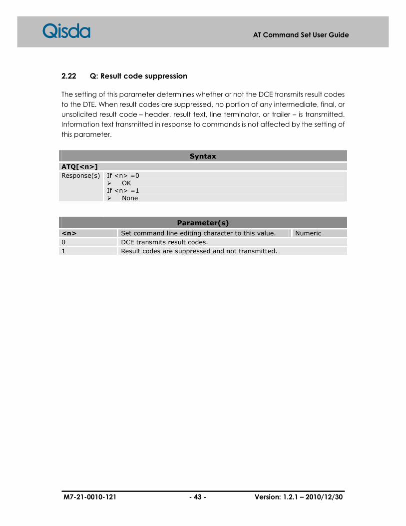
2.22 Q: Result code suppression
The setting of this parameter determines whether or not the DCE transmits result codes
to the DTE. When result codes are suppressed, no portion of any intermediate, final, or
unsolicited result code – header, result text, line terminator, or trailer – is transmitted.
Information text transmitted in response to commands is not affected by the setting of
this parameter.
Syntax
ATQ[<n>]
Response(s) If <n> =0 � OK If <n> =1 � None
Parameter(s)
<n> Set command line editing character to this value. Numeric
0 DCE transmits result codes.
1 Result codes are suppressed and not transmitted.

M7-21-0010-121 - 44 - Version: 1.2.1 – 2010/12/30
AT Command Set User Guide
2.23 V: DCE response format
The setting of this parameter determines the contents of the header and trailer
transmitted with result codes and information responses. It also determines whether
result codes are transmitted in a numeric form or an alphabetic (or "verbose") form.
The text portion of information responses is not affected by this setting.
Syntax
ATV[<value>]
Response(s) When value=0 � 0 When value=1 � OK
Parameter(s)
<value> DCE transmits full headers and trailers and verbose response text.
Numeric
0 DCE transmits limited headers and trailers and numeric text.
1 DCE transmits full headers and trailers and verbose response text.
M7-21-0010-121 - 45 - Version: 1.2.1 – 2010/12/30
AT Command Set User Guide
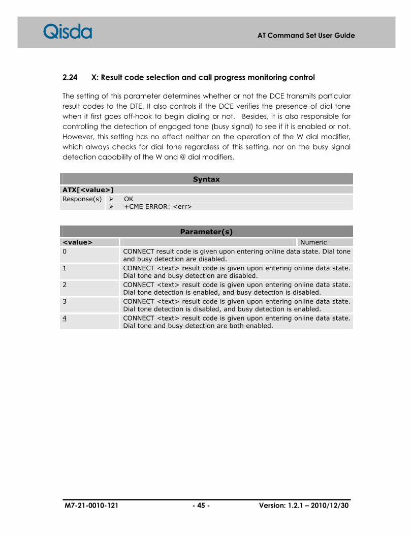
2.24 X: Result code selection and call progress monitoring control
The setting of this parameter determines whether or not the DCE transmits particular
result codes to the DTE. It also controls if the DCE verifies the presence of dial tone
when it first goes off-hook to begin dialing or not. Besides, it is also responsible for
controlling the detection of engaged tone (busy signal) to see if it is enabled or not.
However, this setting has no effect neither on the operation of the W dial modifier,
which always checks for dial tone regardless of this setting, nor on the busy signal
detection capability of the W and @ dial modifiers.
Syntax
ATX[<value>]
Response(s) � OK � +CME ERROR: <err>
Parameter(s)
<value> Numeric
0 CONNECT result code is given upon entering online data state. Dial tone and busy detection are disabled.
1 CONNECT <text> result code is given upon entering online data state. Dial tone and busy detection are disabled.
2 CONNECT <text> result code is given upon entering online data state. Dial tone detection is enabled, and busy detection is disabled.
3 CONNECT <text> result code is given upon entering online data state. Dial tone detection is disabled, and busy detection is enabled.
4 CONNECT <text> result code is given upon entering online data state. Dial tone and busy detection are both enabled.

M7-21-0010-121 - 46 - Version: 1.2.1 – 2010/12/30
AT Command Set User Guide
2.25 &C: Circuit 109 (Received line signal detector) behavior
This parameter determines how the state of circuit 109 relates to the detection of
received line signal from the distant end. Changing the parameter will take effect
immediately in both the command and online command states.
In &C1 mode of operation, circuit 109 is not turned off until all data previously
received from the remote DCE is delivered to the local DTE. However, such buffered
data shall be discarded and circuit 109 has to be turned off if the DTE turns off circuit
108 (if &D1 or &D2 is set).
Syntax
AT&C[<value>]
Response(s) � OK � +CME ERROR: <err>
Parameter(s)
<value> Numeric
0 The DCE always presents the ON condition on circuit 109.
1 Circuit 109 changes in accordance with the underlying DCE, which may include functions other than the physical layer functions (e.g. Recommendation V.42, V.110, V.120 and V.13).
M7-21-0010-121 - 47 - Version: 1.2.1 – 2010/12/30
AT Command Set User Guide
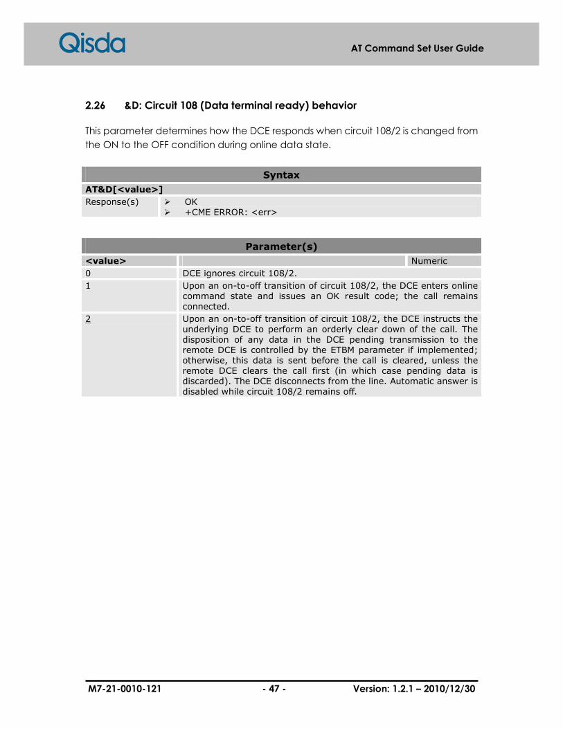
2.26 &D: Circuit 108 (Data terminal ready) behavior
This parameter determines how the DCE responds when circuit 108/2 is changed from
the ON to the OFF condition during online data state.
Syntax
AT&D[<value>]
Response(s) � OK � +CME ERROR: <err>
Parameter(s)
<value> Numeric
0 DCE ignores circuit 108/2.
1 Upon an on-to-off transition of circuit 108/2, the DCE enters online command state and issues an OK result code; the call remains connected.
2 Upon an on-to-off transition of circuit 108/2, the DCE instructs the underlying DCE to perform an orderly clear down of the call. The disposition of any data in the DCE pending transmission to the remote DCE is controlled by the ETBM parameter if implemented; otherwise, this data is sent before the call is cleared, unless the remote DCE clears the call first (in which case pending data is discarded). The DCE disconnects from the line. Automatic answer is disabled while circuit 108/2 remains off.

M7-21-0010-121 - 48 - Version: 1.2.1 – 2010/12/30
AT Command Set User Guide
2.27 +IPR: Fixed DTE rate
This command, the numeric extended-format parameter specifies the data rate
which the DCE will accept. in addition to 1200 bit/s or 9600 bit/s. It may be used to
choose operation with the rates which the DCE is not capable of automatically
detecting the data rate that is being used by the DTE. Specifying a value of 0 disables
the function and allows operation only at rates which can be automatically detected
by the DCE. The specified rate takes effect according to the issuance of any result
code(s) associated with the current command line.
The rate specified does not apply to online Data State if direct mode of operation is
chose.
The rate value specified shall be calculated in bits per second for the DTE-DCE
interface to handle, e.g. "19 200" or "115 200". The rates supported by a particular DCE
are manufacturer-specific; however, the IPR parameter should permit the setting of
any rate supported by the DCE during online operation. Rates which include a
non-integral number of bits per second should be truncated to the next lower integer
(e.g. 134. 5 bit/s should be specified as 134; 45.45 bit/s should be specified as 45). If
the rate is unspecified or set to 0, automatic detection will pick up a rate. In addition,
the character format is also forced to auto-detect, ICF 0.
It is recommended that the default value for this parameter is set to be the automatic
detection setting (0), which facilitates initial DTE-DCE communications.
Syntax
AT+IPR=<rate>
Response(s) � OK � +CME ERROR: <err>
AT+IPR?
Response(s) � +IPR:<rate> OK
� +CME ERROR: <err>
AT+IPR=?
Response(s) � +IPR: (list of auto-detected <rate>s),(list of fixed-only <rate>s) OK
� +CME ERROR: <err>
Parameter(s)
<rate> Baud rate Numeric
75 75 bit/s

M7-21-0010-121 - 49 - Version: 1.2.1 – 2010/12/30
AT Command Set User Guide
150 150 bit/s
300 300 bit/s
600 600 bit/s
1200 1200 bit/s
2400 2400 bit/s
4800 4800 bit/s
7200 7200 bit/s
9600 9600 bit/s
14400 14400 bit/s
19200 19200 bit/s
28800 28800 bit/s
33900 33900 bit/s
38400 38400 bit/s
57600 57600 bit/s
115200 115200 bit/s

M7-21-0010-121 - 50 - Version: 1.2.1 – 2010/12/30
AT Command Set User Guide
2.28 +ICF: DTE-DCE character framing
This extended-format compound parameter is used to determine the local serial port
start-stop (asynchronous) character framing that the DCE shall use while accepting
DTE commands and while transmitting information text and result code, if this is not
automatically determined; IPR 0 forces ICF 0. Note that the definition of fixed
character format for online data state is for further study.
Format determines the number of bits in the data bits, the presence of a parity bit,
and the number of stop bits in the start-stop frame.
Syntax
AT+ICF=[<format>[,<parity>]]
Response(s) � OK � +CME ERROR: <err>
AT+ICF?
Response(s) � +ICF: <format>[,<parity>] OK
� +CME ERROR: <err>
AT+ICF=?
Response(s) � +ICF: (list of supported <format>s),(list of supported <parity>s) OK
� +CME ERROR: <err>
Parameter(s)
format Valid numeric values Numeric
1 8 Data 2 Stop
2 8 Data 1 Parity 1 Stop
3 8 Data 1 Stop
4 7 Data 2 Stop
5 7 Data 1 Parity 1 Stop
6 7 Data 1 Stop
parity Defined numeric values Numeric
0 Odd
1 Even
2 Mark
3 Space
Example(s)
DTE-DCE character framing
AT+ICF=? +ICF: (1-6),(0-3) OK
1. Get character framing
M7-21-0010-121 - 51 - Version: 1.2.1 – 2010/12/30
AT Command Set User Guide
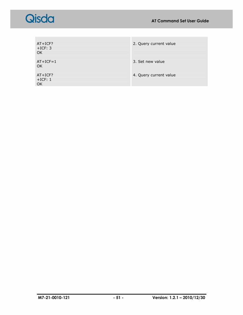
AT+ICF? +ICF: 3 OK AT+ICF=1 OK AT+ICF? +ICF: 1 OK
2. Query current value 3. Set new value 4. Query current value

M7-21-0010-121 - 52 - Version: 1.2.1 – 2010/12/30
AT Command Set User Guide
2.29 +IFC: DTE-DCE local flow control
This extended-format compound parameter is used to control the operation of local
flow control between the DTE and DCE during the data state while V.42 error control is
being used, or when fallback to non-error control mode is specified to include
buffering and flow control.
Syntax
AT+IFC=[<DCE_by_DTE>[,<DTE_by_DCE>]]
Response(s) � OK � +CME ERROR: <err>
AT+IFC?
Response(s) � +IFC:<DCE_by_DTE>,<DTE_by_DCE> OK
� +CME ERROR: <err>
AT+IFC=?
Response(s) � +IFC: (list of <DCE_by_DTE>),(list of <DTE_by_DCE>) OK
� +CME ERROR: <err>
Parameter(s)
<DCE_by_DTE> Specifies the method to be used by the DTE to control the flow of received data from the DCE
Numeric
0 None
1 DC1/DC3 on circuit 103; do not pass DC1/DC3 characters to the remote DCE
2 Circuit 133 (Ready for Receiving)
<DTE_by_DCE> Specifies the method to be used by the DCE to control the flow of transmitted data from the DTE
Numeric
0 None
1 DC1/DC3 on circuit 104
2 Circuit 106 (Clear to Send/Ready for Sending)
Example(s)
DTE-DCE local flow control
AT+IFC=? +IFC: (0-2),(0-2) OK AT+IFC? +IFC: 2,2 OK AT+IFC=0,0 OK
1. List local flow control option 2. Query current value 3. Set new value

M7-21-0010-121 - 53 - Version: 1.2.1 – 2010/12/30
AT Command Set User Guide
AT+IFC? +IFC: 0,0 OK
4. Query current value

M7-21-0010-121 - 54 - Version: 1.2.1 – 2010/12/30
AT Command Set User Guide
2.30 +ILRR: DTE-DCE local rate reporting
This extended-format numeric parameter controls whether or not the
extended-format "ILRR: rate" information text is transmitted from the DCE to the DTE.
The rate reported shall represent the current DTE-DCE rate. If it is enabled, the
intermediate result code is transmitted after any modulation, error control or data
compression reports are transmitted, but before any final result code (e.g. CONNECT)
is transmitted. The rate is applied after the final result code is transmitted.
The DTE-DCE port rate will only be changed under the situations of (1) neither
buffered mode nor error-controlled means are enabled (ESx,0); (2) the
negotiated carrier rate (MRR) does not match the current DTE-DCE port rate (set by
IPR command or auto-detected from the previous command line).
Syntax
AT+ILRR=<mode>
Response(s) � OK � +CME ERROR: <err>
AT+ILRR?
Response(s) � +ILRR:<mode> OK
� +CME ERROR: <err>
AT+ILRR=?
Response(s) � +ILRR: (list of supported <mode>s) OK
� +CME ERROR: <err>
Unsolicited Result Codes
� ILRR: <rate>
Parameter(s)
<mode> Reporting mode Numeric
0 Disables reporting of local port rate (+ILRR: is not transmitted)
1 Enables reporting of local port rate (+ILRR: is transmitted)
<rate> Port rate setting upon connection setup (bps) Numeric
Example(s)
DTE-DCE local rate reporting
AT+ILRR=? +ILRR: (0,1) OK AT+ILRR? +ILRR: 0
1. Get local rate reporting 2. Query current value
M7-21-0010-121 - 55 - Version: 1.2.1 – 2010/12/30
AT Command Set User Guide
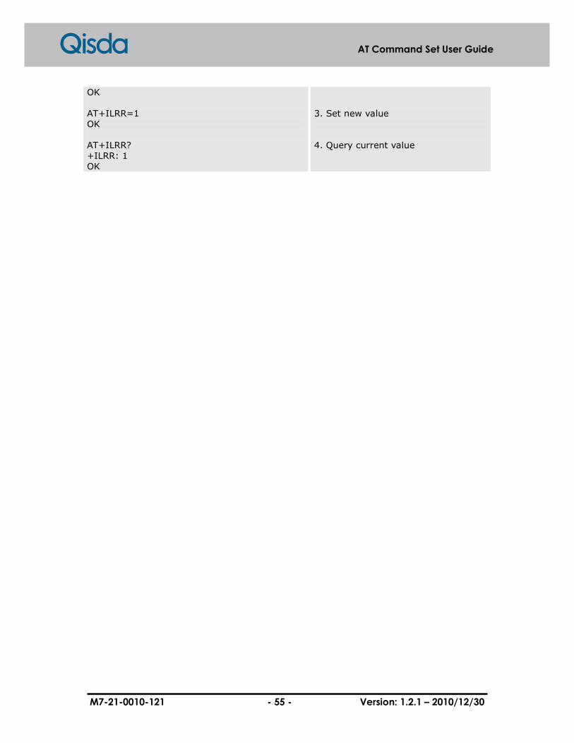
OK AT+ILRR=1 OK AT+ILRR? +ILRR: 1 OK
3. Set new value 4. Query current value
M7-21-0010-121 - 56 - Version: 1.2.1 – 2010/12/30
AT Command Set User Guide
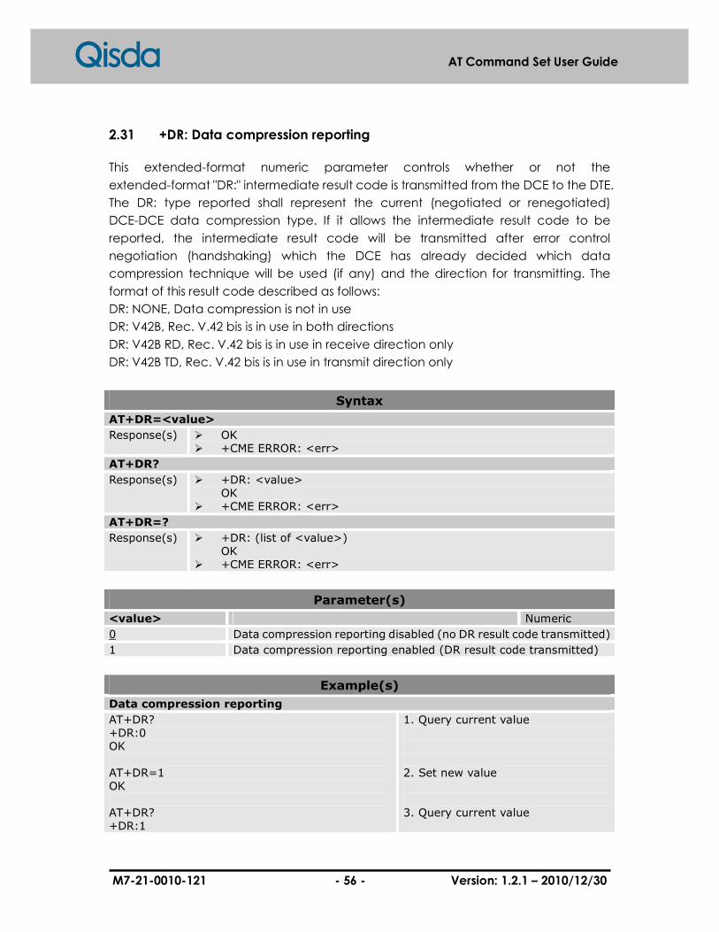
2.31 +DR: Data compression reporting
This extended-format numeric parameter controls whether or not the
extended-format "DR:" intermediate result code is transmitted from the DCE to the DTE.
The DR: type reported shall represent the current (negotiated or renegotiated)
DCE-DCE data compression type. If it allows the intermediate result code to be
reported, the intermediate result code will be transmitted after error control
negotiation (handshaking) which the DCE has already decided which data
compression technique will be used (if any) and the direction for transmitting. The
format of this result code described as follows:
DR: NONE, Data compression is not in use
DR: V42B, Rec. V.42 bis is in use in both directions
DR: V42B RD, Rec. V.42 bis is in use in receive direction only
DR: V42B TD, Rec. V.42 bis is in use in transmit direction only
Syntax
AT+DR=<value>
Response(s) � OK � +CME ERROR: <err>
AT+DR?
Response(s) � +DR: <value> OK
� +CME ERROR: <err>
AT+DR=?
Response(s) � +DR: (list of <value>) OK
� +CME ERROR: <err>
Parameter(s)
<value> Numeric
0 Data compression reporting disabled (no DR result code transmitted)
1 Data compression reporting enabled (DR result code transmitted)
Example(s)
Data compression reporting
AT+DR? +DR:0 OK AT+DR=1 OK AT+DR? +DR:1
1. Query current value 2. Set new value 3. Query current value

M7-21-0010-121 - 57 - Version: 1.2.1 – 2010/12/30
AT Command Set User Guide
OK

M7-21-0010-121 - 58 - Version: 1.2.1 – 2010/12/30
AT Command Set User Guide
2.32 $TIME: RTC TIME
This command is used to set the time in RTC. It uses the 24-Hour format.
Syntax
AT$TIME=<HH,MM,SS>
Response(s) � HH/MM/DD OK � +CMS ERROR: <err>
AT$TIME?
Response(s) � HH/MM/DD OK
AT$TIME=?
Response(s) � $TIME: <HH>,<MM>,<SS> OK
Parameter(s)
<HH> The hour field Numeric
0-23
<MM> The minute field Numeric
0-59
<SS> The second field Numeric
0-59
Example(s)
Set time
AT$TIME=19,07,09 19/07/09 OK
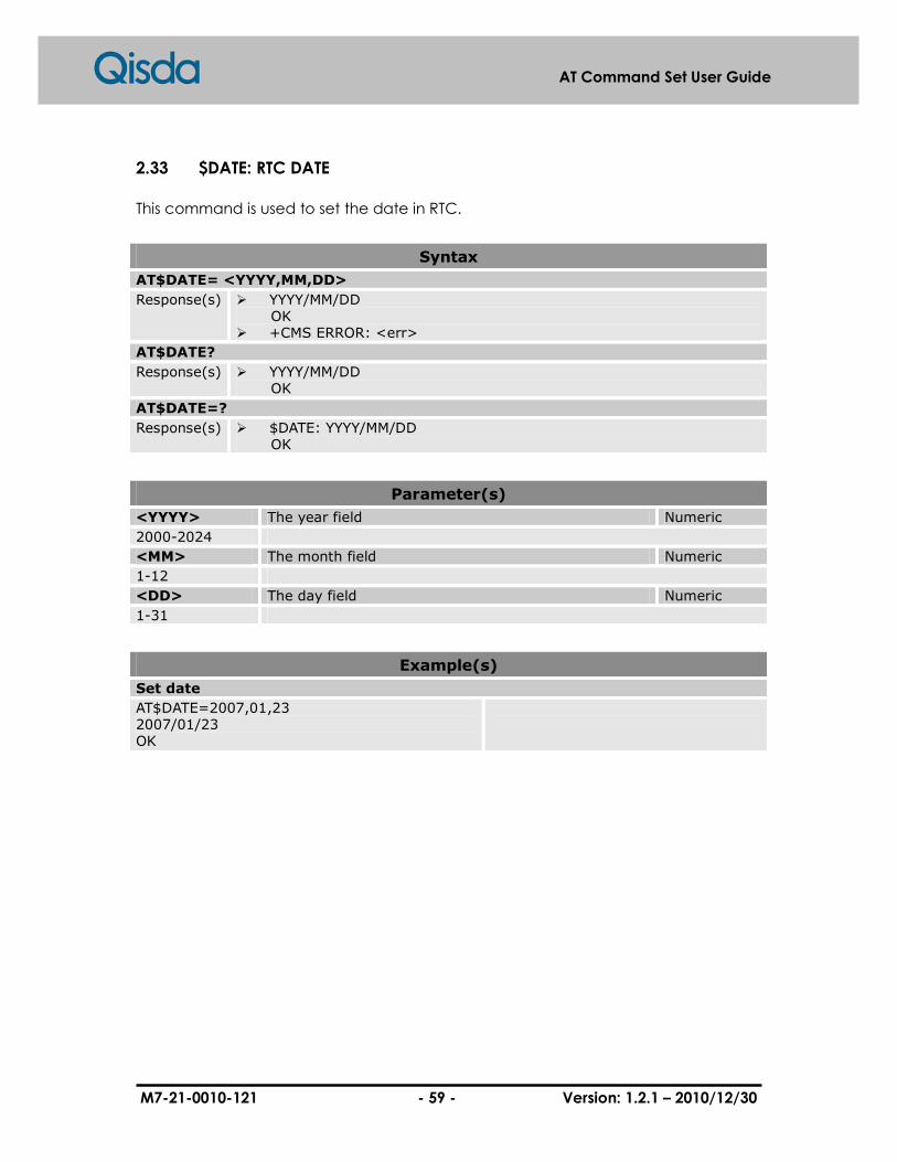
M7-21-0010-121 - 59 - Version: 1.2.1 – 2010/12/30
AT Command Set User Guide
2.33 $DATE: RTC DATE
This command is used to set the date in RTC.
Syntax
AT$DATE= <YYYY,MM,DD>
Response(s) � YYYY/MM/DD OK � +CMS ERROR: <err>
AT$DATE?
Response(s) � YYYY/MM/DD OK
AT$DATE=?
Response(s) � $DATE: YYYY/MM/DD OK
Parameter(s)
<YYYY> The year field Numeric
2000-2024
<MM> The month field Numeric
1-12
<DD> The day field Numeric
1-31
Example(s)
Set date
AT$DATE=2007,01,23 2007/01/23 OK

M7-21-0010-121 - 60 - Version: 1.2.1 – 2010/12/30
AT Command Set User Guide
3 Call Control Commands
3.1 +CSTA: Select Type of Address
Set command selects a specific number for further dialing command (D) according
to GSM/UMTS specifications. Test command returns values supported by the TA as a
compound value.
Syntax
+CSTA=<type>
Response(s) � OK � +CME ERROR: <err>
AT+CSTA?
Response(s) � +CSTA: <type> OK
� +CME ERROR: <err>
AT+CSTA=?
Response(s) � +CSTA: (list of supported <type>s) OK
� +CME ERROR: <err>
Parameter(s)
<type> Type of address octet in integer Numeric
129 Dialing string without international access code “+”.
145 Dialing string includes international access code character “+”.
Example(s)
Set type of address
AT+CSTA=145 OK
1. Set address type to 145
List all available types
AT+CSTA=? +CSTA: (129,145) OK
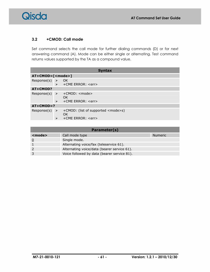
M7-21-0010-121 - 61 - Version: 1.2.1 – 2010/12/30
AT Command Set User Guide
3.2 +CMOD: Call mode
Set command selects the call mode for further dialing commands (D) or for next
answering command (A). Mode can be either single or alternating. Test command
returns values supported by the TA as a compound value.
Syntax
AT+CMOD=[<mode>]
Response(s) � OK � +CME ERROR: <err>
AT+CMOD?
Response(s) � +CMOD: <mode> OK
� +CME ERROR: <err>
AT+CMOD=?
Response(s) � +CMOD: (list of supported <mode>s) OK
� +CME ERROR: <err>
Parameter(s)
<mode> Call mode type Numeric
0 Single mode.
1 Alternating voice/fax (teleservice 61).
2 Alternating voice/data (bearer service 61).
3 Voice followed by data (bearer service 81).

M7-21-0010-121 - 62 - Version: 1.2.1 – 2010/12/30
AT Command Set User Guide
3.3 +CHUP: Hang up call
Execution command causes the TA to hang up the current GSM/UMTS call of the ME.
Syntax
AT+CHUP
Response(s) � OK � +CME ERROR: <err>
AT+CHUP=?
Response(s) � OK

M7-21-0010-121 - 63 - Version: 1.2.1 – 2010/12/30
AT Command Set User Guide
3.4 +CBST: Select bearer service type
Set command is able to set the bearer service <name> together with data rate
<speed> and the connection element <ce> which is used when data calls occurred.
Values may also be used during mobile terminated data call setup, especially in the
situation that single numbering scheme calls in/out.
Syntax
AT+CBST=[<speed>[,<name>[,<ce>]]]
Response(s) � OK � +CME ERROR: <err>
AT+CBST?
Response(s) � +CBST: <speed>,<name>,<ce> OK
� +CME ERROR: <err>
AT+CBST=?
Response(s) � +CBST: (list of supported <speed>s),(list of supported <name>s), (list of supported <ce>s) OK
� +CME ERROR: <err>
Parameter(s)
<speed> Data rate of bearer service Numeric
0 Autobauding
1 300 bps (V.21).
2 1200 bps (V.22).
3 1200/75 bps (V.23).
4 2400 bps (V.22bis).
5 2400 bps (V.26ter).
6 4800 bps (V.32).
7 9600 bps (V.32).
12 9600bps (V.34).
14 14400 bps (V.34).
65 300 bps (V.110).
66 1200 bps (V.110).
68 2400 bps (V.110 or X.31 flag stuffing).
70 4800 bps (V.110 or X.31 flag stuffing).
71 9600 bps (V.110 or X.31 flag stuffing).
75 14400 bps (V.110 or X.31 flag stuffing).
<name> Bearer service type Numeric
0 Data circuit asynchronous (UDI or 3.1k HZ modem).
<ce> Connection element Numeric
0 Transparent.
1 Non-transparent.

M7-21-0010-121 - 64 - Version: 1.2.1 – 2010/12/30
AT Command Set User Guide
2 Both, transparent preferred.
3 Both, non-transparent preferred.
Example(s)
Set bearer service type
AT+CBST=6,0,1 OK AT+CBST? +CBST: 6,0,1 OK
1. Change bearer service type 2. Query setting status
List all available types
AT+CBST=? +CBST: (0-7,12,14,65,66,68,70,71,75),(0),(0-3) OK

M7-21-0010-121 - 65 - Version: 1.2.1 – 2010/12/30
AT Command Set User Guide
3.5 +CRLP: Radio link protocol
Radio link protocol (RLP) parameters used when non-transparent data calls occurred,
but may be changed by set command. Available command sub-parameters may
be provided depends on the RLP versions implemented by the device (currently only
version 1 is supported).
Read command returns current setting for supported RLP version. Test command
returns values supported by the TA as a compound value.
Syntax
AT+CRLP=[<iws>[,<mws>[,<T1>[,<N2>]]]]
Response(s) � OK � +CME ERROR: <err>
AT+CRLP?
Response(s) � +CRLP: <iws>,<mws>,<T1>,<N2> OK
� +CME ERROR: <err>
AT+CRLP=?
Response(s) � +CRLP: (list of supported <iws>s),(list of supported <mws>s),(list of supported <T1>s),(list of supported <N2>s) OK
� +CME ERROR: <err>
Parameter(s)
<iws> IWF to MS window size Numeric
0–61
<mws> MS to IWF window size Numeric
0–61
<T1> Acknowledgement timer (units of 10 ms) Numeric
39–255 Default value: 48
<N2> Retransmission attempts Numeric
1–255 Default value: 6
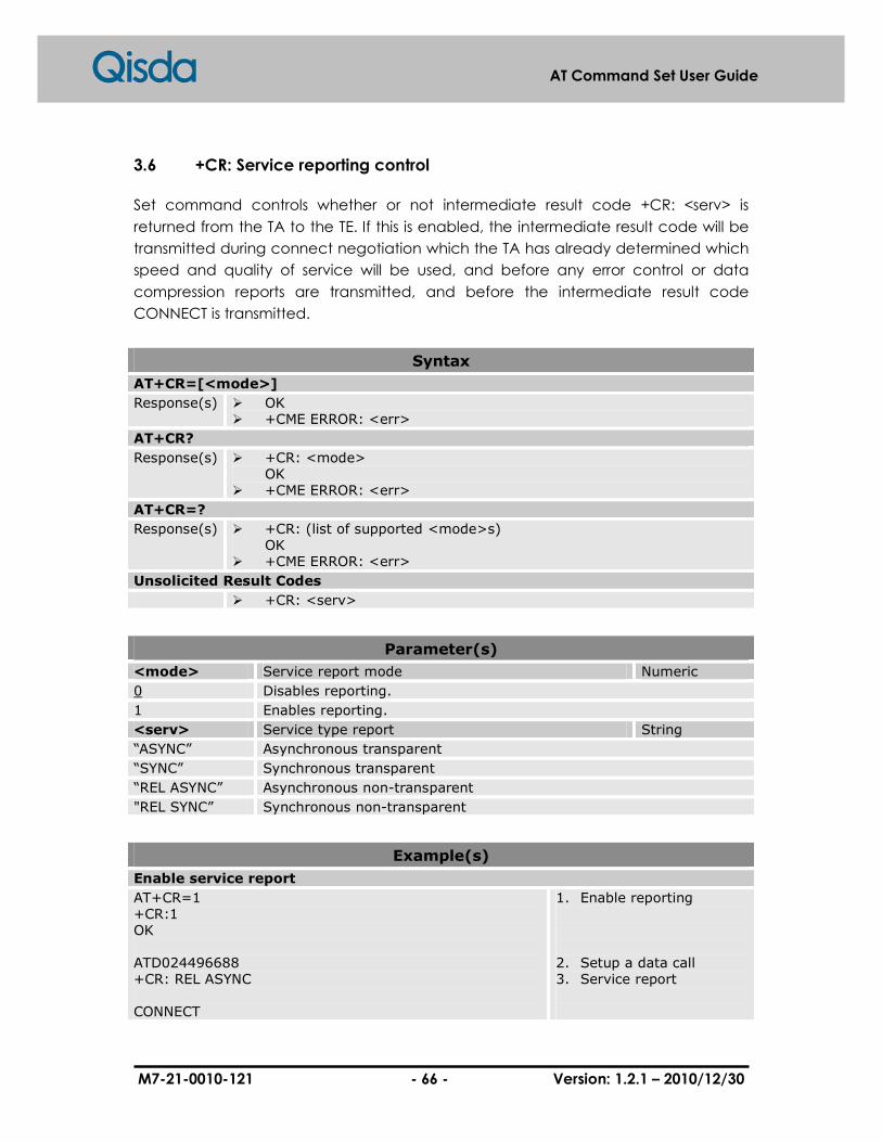
M7-21-0010-121 - 66 - Version: 1.2.1 – 2010/12/30
AT Command Set User Guide
3.6 +CR: Service reporting control
Set command controls whether or not intermediate result code +CR: <serv> is
returned from the TA to the TE. If this is enabled, the intermediate result code will be
transmitted during connect negotiation which the TA has already determined which
speed and quality of service will be used, and before any error control or data
compression reports are transmitted, and before the intermediate result code
CONNECT is transmitted.
Syntax
AT+CR=[<mode>]
Response(s) � OK � +CME ERROR: <err>
AT+CR?
Response(s) � +CR: <mode> OK
� +CME ERROR: <err>
AT+CR=?
Response(s) � +CR: (list of supported <mode>s) OK
� +CME ERROR: <err>
Unsolicited Result Codes
� +CR: <serv>
Parameter(s)
<mode> Service report mode Numeric
0 Disables reporting.
1 Enables reporting.
<serv> Service type report String
“ASYNC” Asynchronous transparent
“SYNC” Synchronous transparent
“REL ASYNC” Asynchronous non-transparent
"REL SYNC” Synchronous non-transparent
Example(s)
Enable service report
AT+CR=1 +CR:1 OK ATD024496688 +CR: REL ASYNC CONNECT
1. Enable reporting 2. Setup a data call 3. Service report
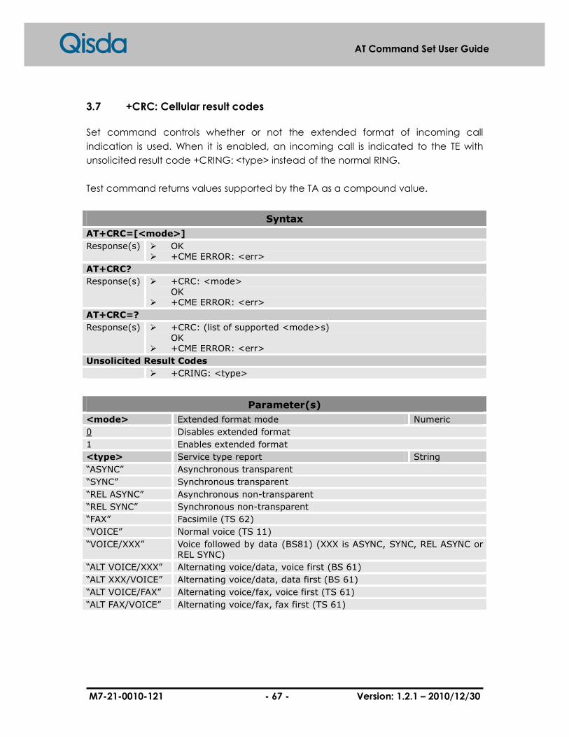
M7-21-0010-121 - 67 - Version: 1.2.1 – 2010/12/30
AT Command Set User Guide
3.7 +CRC: Cellular result codes
Set command controls whether or not the extended format of incoming call
indication is used. When it is enabled, an incoming call is indicated to the TE with
unsolicited result code +CRING: <type> instead of the normal RING.
Test command returns values supported by the TA as a compound value.
Syntax
AT+CRC=[<mode>]
Response(s) � OK � +CME ERROR: <err>
AT+CRC?
Response(s) � +CRC: <mode> OK
� +CME ERROR: <err>
AT+CRC=?
Response(s) � +CRC: (list of supported <mode>s) OK
� +CME ERROR: <err>
Unsolicited Result Codes
� +CRING: <type>
Parameter(s)
<mode> Extended format mode Numeric
0 Disables extended format
1 Enables extended format
<type> Service type report String
“ASYNC” Asynchronous transparent
“SYNC” Synchronous transparent
“REL ASYNC” Asynchronous non-transparent
“REL SYNC” Synchronous non-transparent
“FAX” Facsimile (TS 62)
“VOICE” Normal voice (TS 11)
“VOICE/XXX” Voice followed by data (BS81) (XXX is ASYNC, SYNC, REL ASYNC or REL SYNC)
“ALT VOICE/XXX” Alternating voice/data, voice first (BS 61)
“ALT XXX/VOICE” Alternating voice/data, data first (BS 61)
“ALT VOICE/FAX” Alternating voice/fax, voice first (TS 61)
“ALT FAX/VOICE” Alternating voice/fax, fax first (TS 61)

M7-21-0010-121 - 68 - Version: 1.2.1 – 2010/12/30
AT Command Set User Guide
Example(s)
Enables extended format
AT+CRC=1 OK +CRING: VOICE
1. Enables extended format 2. MT call indication

M7-21-0010-121 - 69 - Version: 1.2.1 – 2010/12/30
AT Command Set User Guide
3.8 +CSNS: Single numbering scheme
Set command can set the bearer or teleservice should be used when mobile
terminated single numbering scheme call is established. Parameter values set with
+CBST command shall be used when <mode> equals to a data service.
Test command returns values supported by the TA as a compound value.
Syntax
AT+CSNS=[<mode>]
Response(s) � OK � +CME ERROR: <err>
AT+CSNS?
Response(s) � +CSNS: <mode> OK
� +CME ERROR: <err>
AT+CSNS=?
Response(s) � +CSNS: (list of supported <mode>s) OK
� +CME ERROR: <err>
Parameter(s)
<mode> Service mode Numeric
0 Voice
1 Alternating voice/fax, voice first (TS 61)
2 Fax (TS 62)
3 Alternating voice/data, voice first (BS 61)
4 Data
5 Alternating voice/fax, fax first (TS 61)
6 Alternating voice/data, data first (BS 61)
7 Voice followed by data (BS 81)

M7-21-0010-121 - 70 - Version: 1.2.1 – 2010/12/30
AT Command Set User Guide
3.9 D: Dial
This command instructs the DCE to create a call. This may include several steps,
depending upon the DCE type, such as: connecting to the line (going off-hook),
waiting for the network to indicate readiness to receive call addressing information
(wait for dial tone), signaling call addressing information to the network (dialling the
number), monitoring the line for call progress signals (e.g. busy), and instructing the
underlying DCE to start the call procedure (modulation handshaking).
All characters follow the "D" and up to a semicolon character (IA5 3/11) or the end of
the command line are considered to be part of the call addressing information and
be signaled to the network, or to be modifiers used for controlling the signaling
process (this is known as a "dial string"). If the dial string is terminated by a semicolon,
the DCE does not start the call procedure defined for the underlying DCE, but returns
to command state instead after signaling the call addressing information to the
network.
Any characters within the dial string that the DCE does not recognize as a valid part
of the call addressing information or a valid modifier shall be ignored. This permits
characters such as parentheses and hyphens to be included since they are typically
used as part of the telephone numbers.
Syntax
ATD[<dial_string>][;]
Response(s) � CONNECT If connection is successfully established and X0 is selected. This result code is transmitted immediately before circuit 109 is turned on. � CONNECT <text>
If Connection is successfully established and Xn is selected where "n" is any value other than 0. This result code is transmitted immediately before circuit 109 is turned on. The contents of text are manufacturer -specific, and may include indication of DTE interface speed, line speed, error control and data compression techniques in use, and other information � NO CARRIER If a connection cannot be established, or was aborted by reception of an additional character from the DTE � ERROR If issued while in online command state � BUSY
If busy signal detection is enabled or the W or @ dial modifier is used, and a busy signal is detected � NO ANSWER
If the "@" dial modifier is used, and remote ringing followed by five seconds of silence is not detected before the expiration of the connection timer defined by S7
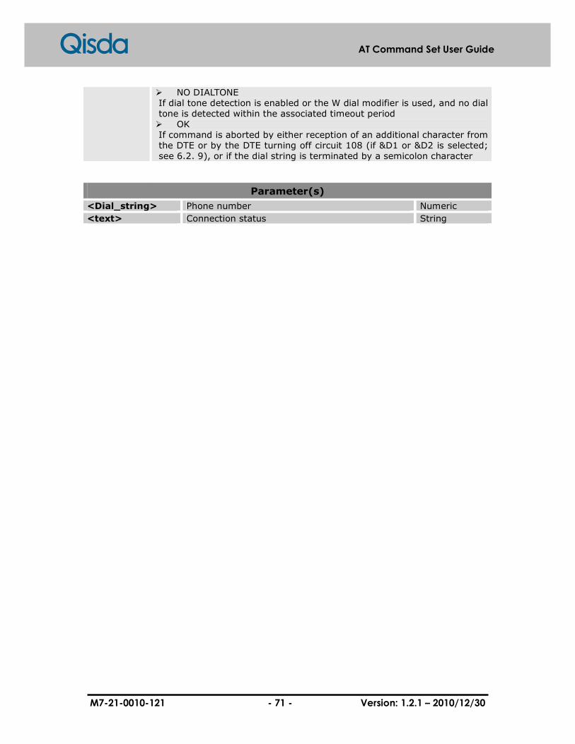
M7-21-0010-121 - 71 - Version: 1.2.1 – 2010/12/30
AT Command Set User Guide
� NO DIALTONE If dial tone detection is enabled or the W dial modifier is used, and no dial
tone is detected within the associated timeout period � OK
If command is aborted by either reception of an additional character from the DTE or by the DTE turning off circuit 108 (if &D1 or &D2 is selected; see 6.2. 9), or if the dial string is terminated by a semicolon character
Parameter(s)
<Dial_string> Phone number Numeric
<text> Connection status String

M7-21-0010-121 - 72 - Version: 1.2.1 – 2010/12/30
AT Command Set User Guide
3.10 W: Wait for dial tone
This causes DCE to listen to dial tone on the line. If a valid dial tone is detected, the
DCE continues processing the remainder of the dial string.
If DCE decides to abort dialing because the dial tone does not occur within the
connection timeout period specified by parameter S7, the NO DIALTONE or NO
CARRIER result code is issued and the remainder of the command line is ignored.
The DCE may, but is not required to, detect busy signal while listening to dial tone. This
capability may be conditioned upon the setting of the X command. The BUSY or NO
CARRIER result codes may be issued if the DCE detects a busy signal while listening to
dial tone; in this event, the remainder of the command line is ignored.
Syntax
ATW
Response(s) � OK � +CME ERROR: <err>
M7-21-0010-121 - 73 - Version: 1.2.1 – 2010/12/30
AT Command Set User Guide
3.11 T: Select tone dialing (dial modifier)
This causes subsequent dial digits to be signaled using DTMF. The effect of the T
modifier may forward to subsequent D commands (i.e. once a T dial modifier is used,
all subsequent dialing uses DTMF tones until a P dial modifier or command is issued);
however, it is recommended that the DTE explicitly specify pulse or DTMF dialing with
an appropriate dial modifier (P or T) at the beginning of each dial string.
Syntax
ATT
Response(s) � OK � +CME ERROR: <err>

M7-21-0010-121 - 74 - Version: 1.2.1 – 2010/12/30
AT Command Set User Guide
3.12 P: Select pulse dialing (dial modifier)
The effect of the P modifier may forward to subsequent D commands (i.e. once a P
dial modifier is used, all subsequent dialing uses pulse dialing until a T dial modifier or
command is issued); however, it is recommended that the DTE explicitly specify pulse
or DTMF dialing with an appropriate dial modifier (P or T) at the beginning of each dial
string.
Syntax
ATP
Response(s) � OK � +CME ERROR: <err>
M7-21-0010-121 - 75 - Version: 1.2.1 – 2010/12/30
AT Command Set User Guide
3.13 A: Answer
This command instructs the DCE to immediately connect to the line and start the
answer sequence as specified from the underlying DCE.
Any additional commands that follow A on the same command line are ignored.
Syntax
ATA
Response(s) � CONNECT If connection is successfully established and X0 is selected. This result code is transmitted immediately before circuit 109 is turned on � CONNECT <text> If connection is successfully established and Xn is selected where "n" is any value other than 0. This result code is transmitted immediately before circuit 109 is turned on. The contents of text are manufacturer -specific, and may include indication of DTE interface speed, line speed, error control and data compression techniques in use, and other information � NO CARRIER If a connection cannot be established, or was aborted by reception of an additional character from the DTE � ERROR If issued while in online command state � OK If command is aborted by either reception of an additional character from the DTE or by the DTE turning off circuit 108 (if &D1 or &D2 is selected; see 6.2. 9), or if the dial string is terminated by a semicolon character
Parameter(s)
<text> Connection status String

M7-21-0010-121 - 76 - Version: 1.2.1 – 2010/12/30
AT Command Set User Guide
3.14 H: Hook control
This command instructs the DCE to disconnect from the line, terminate any call in
progress. All functions of the command shall be completed before DCE issues any
result code.
Syntax
ATH[value]
Response(s) � OK � +CME ERROR: <err>
Parameter(s)
<value> Numeric
0 Disconnect from line and terminate call.

M7-21-0010-121 - 77 - Version: 1.2.1 – 2010/12/30
AT Command Set User Guide
3.15 S0: Automatic answer
This S-parameter controls the automatic answering feature of the DCE. If it is set to 0,
automatic answering is disabled. On the other hand, If it is set to a non-zero value, the
DCE shall be responsible for answering once the incoming call indication (ring) has
occurred for the specific times indicated by the value. For example, in GSTN modem
applications, setting this parameter to 1 will cause the modem to answer an incoming
call on the first ring.
Syntax
ATS0=<n>
Response(s) � OK � +CME ERROR: <err>
ATS0?
Response(s) � <n> OK
� +CME ERROR: <err>
ATS0=?
Response(s) � S0: (list of supported <n>s) OK
� +CME ERROR: <err>
Parameter(s)
<n> Numeric
0 Automatic answering is disabled.
1-255 Enable automatic answering on the ring number specified.
Example(s)
Automatic answer
ATS0=? S0(0-255) OK ATS0? 000 OK ATS0=1 OK ATS0? 001 OK
1. Get parameter 2. Query current value 3. Set new value 4. Query current value

M7-21-0010-121 - 78 - Version: 1.2.1 – 2010/12/30
AT Command Set User Guide
3.16 L: Monitor speaker loudness
This parameter controls the volume of the monitor speaker. The specific loudness level
indicated by "low", "medium", and "high" depends on manufacturer-specific,
although they are intended to indicate increasing volume.
Syntax
ATL[value]
Response(s) � OK � +CME ERROR: <err>
Parameter(s)
<value> Speaker volume Numeric
0 Low speaker volume
1 Low speaker volume
2 Medium speaker volume
3 High speaker volume
M7-21-0010-121 - 79 - Version: 1.2.1 – 2010/12/30
AT Command Set User Guide
3.17 +++: Escape from data mode
This command is used to escape from the data mode and enter to command mode.
To prevent misinterpret the data with +++ pattern as escape sequence, it must be
wait for a guard time (1 second) before and after the sequence.
Please refer to ATO which is also the command return to data mode.
Syntax
+++
Response(s) � OK

M7-21-0010-121 - 80 - Version: 1.2.1 – 2010/12/30
AT Command Set User Guide
3.18 O: Return to data mode
This command returns to data mode which escapes via +++ command before.
Please refer to “+++”.
Syntax
ATO
Response(s) Return to data mode successfully. � CONNECT Connection fails. � NO CARRIER
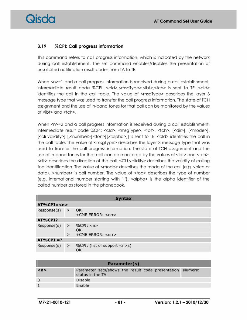
M7-21-0010-121 - 81 - Version: 1.2.1 – 2010/12/30
AT Command Set User Guide
3.19 %CPI: Call progress information
This command refers to call progress information, which is indicated by the network
during call establishment. The set command enables/disables the presentation of
unsolicited notification result codes from TA to TE.
When <n>=1 and a call progress information is received during a call establishment,
intermediate result code %CPI: <cId>,<msgType>,<ibt>,<tch> is sent to TE. <cId>
identifies the call in the call table. The value of <msgType> describes the layer 3
message type that was used to transfer the call progress information. The state of TCH
assignment and the use of in-band tones for that call can be monitored by the values
of <ibt> and <tch>.
When <n>=2 and a call progress information is received during a call establishment,
intermediate result code %CPI: <cId>, <msgType>, <ibt>, <tch>, [<dir>], [<mode>],
[<cli validity>] [,<number>[,<ton>][,<alpha>]] is sent to TE. <cId> identifies the call in
the call table. The value of <msgType> describes the layer 3 message type that was
used to transfer the call progress information. The state of TCH assignment and the
use of in-band tones for that call can be monitored by the values of <ibt> and <tch>.
<dir> describes the direction of the call. <CLI validity> describes the validity of calling
line identification. The value of <mode> describes the mode of the call (e.g. voice or
data). <number> is call number. The value of <toa> describes the type of number
(e.g. international number starting with '+'). <alpha> is the alpha identifier of the
called number as stored in the phonebook.
Syntax
AT%CPI=<n>
Response(s) � OK +CME ERROR: <err>
AT%CPI?
Response(s) � %CPI: <n> OK
� +CME ERROR: <err>
AT%CPI =?
Response(s) � %CPI: (list of support <n>s) OK
Parameter(s)
<n> Parameter sets/shows the result code presentation status in the TA.
Numeric
0 Disable
1 Enable

M7-21-0010-121 - 82 - Version: 1.2.1 – 2010/12/30
AT Command Set User Guide
2 Enable with call number information
<cId> Call identification number as described in GSM 02.30 sub-clause 4.5.5.1
Numeric
<msgType> Layer 3 message type Numeric
0 Setup message
1 Disconnect message
2 Alert message
3 Call proceed message
4 Synchronization message
5 Progress message
6 Call connected message
7 Release message
8 Reject message
9 MO setup
10 Hold
<ibt> Status of the usage of in-band tones Numeric
0 No in-band tones
1 In-band tones
<tch> TCH assignment Numeric
0 TCH not assigned
1 TCH assigned
<dir> Numeric
0 Mobile originated call
1 Mobile terminated call
<mode> Numeric
0 Voice
1 Data
2 Fax
3 Vfdvoice
4 Vadvoice
5 Vafvoice
6 Vfddata
7 Vaddata
8 Vaffax
9 Unknown
<CLI validity> Numeric
0 CLI valid
1 CLI has been withheld by the originator
2 CLI is not available due to inter-working problems or limitations of originating network.
<number> Number of dialed/connected call Numeric
<toa> Type of address octet (ton/npi) Numeric
<alpha> Alpha identifier of dialed/connected call if available in phonebook
Numeric
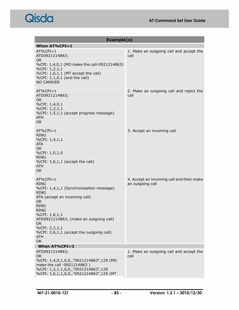
M7-21-0010-121 - 83 - Version: 1.2.1 – 2010/12/30
AT Command Set User Guide
Example(s)
When AT%CPI=1
AT%CPI=1 ATD0921214863; OK %CPI: 1,4,0,1 (MO make the call-0921214863) %CPI: 1,2,1,1 %CPI: 1,6,1,1 (MT accept the call) %CPI: 1,1,0,1 (end the call) NO CARRIER AT%CPI=1 ATD0921214863; OK %CPI: 1,4,0,1 %CPI: 1,2,1,1 %CPI: 1,5,1,1 (accept progress message) ATH OK AT%CPI=1 RING %CPI: 1,4,1,1 ATA OK %CPI: 1,0,1,0 RING %CPI: 1,6,1,1 (accept the call) ATH OK AT%CPI=1 RING %CPI: 1,4,1,1 (Synchronization message) RING ATA (accept an incoming call) OK RING RING %CPI: 1,6,1,1 ATD0921214863; (make an outgoing call) OK %CPI: 2,2,1,1 %CPI: 2,6,1,1 (accept the outgoing call) ATH OK
1. Make an outgoing call and accept the call 2. Make an outgoing call and reject the call
3. Accept an incoming call
4. Accept an incoming call and then make an outgoing call
When AT%CPI=2
ATD0921214863; OK %CPI: 1,4,0,1,0,0,,"0921214863",129 (MO make the call -0921214863 ) %CPI: 1,2,1,1,0,0,,"0921214863",129 %CPI: 1,6,1,1,0,0,,"0921214863",129 (MT
1. Make an outgoing call and accept the call

M7-21-0010-121 - 84 - Version: 1.2.1 – 2010/12/30
AT Command Set User Guide
accept the call) %CPI: 1,1,0,1 NO CARRIER ATD0921214863; OK %CPI: 1,4,0,1,0,0,,"0921214863",129 %CPI: 1,2,1,1,0,0,,"0921214863",129 %CPI: 1,5,1,1,0,0,,"0921214863",129 (MT reject the call and MO get progress message) ATH OK %CPI: 1,0,1,0,1,0,1 RING %CPI: 1,4,1,1,1,0,1 (Synchronization message) ATA (accept the incoming call) OK RING RING %CPI: 1,6,1,1,1,0,1 (connect the call) ATH (hang up the call) OK %CPI: 1,0,1,0,1,0,1 RING %CPI: 1,4,1,1,1,0,1 ATA (accept the incoming call) OK %CPI: 1,6,1,1,1,0,1 (connect the call) ATD0921214863; (make an outgoing call-0921214863) OK %CPI: 2,2,1,1,0,0,1,"0921214863",129 %CPI: 2,6,1,1,0,0,1,"0921214863",129 %CPI: 2,1,0,1 (MT-0921214863 hang up) NO CARRIER ATH (hang up) OK
2. Make an outgoing call and reject the call 3. Accept an incoming call 4. Accept an incoming call and then make an outgoing call

M7-21-0010-121 - 85 - Version: 1.2.1 – 2010/12/30
AT Command Set User Guide
4 Network Service Related Commands
4.1 +CNUM: Subscriber number
Set command returns the MSISDN related to the subscriber (this information can be
stored in the SIM or in the ME.) If subscriber has different MSISDN for different services,
each MSISDN is returned in a separate line (<CR><LF>).
Syntax
AT+CNUM
Response(s) � +CNUM: <alpha>,<number>,<type> OK
� +CME ERROR: <err>
AT+CNUM=?
Response(s) � OK
Parameter(s)
<number> Phone number String
<alpha> Optional alphanumeric string associated with <number>;used character set should be the one selected with command (Select TE Character Set +CSCS).
String
<type> Type of address octet Numeric
129 Dialing string without international access code “+”.
145 Dialing string includes international access code character “+”.
Example(s)
Read subscriber number from MSISDN list
AT+CPBS=”ON” OK AT+CPBW=1,”0960530355”,,”WM0” OK AT+CPBR=1 +CPBR: 1,”0960530355”,129,”WM0” OK AT+CNUM +CNUM: “WM0”,”0960530355”,129 OK
1. Select MSISDN list 2. Write data to location 1 3. Read data from location 1 4. Get subscriber number

M7-21-0010-121 - 86 - Version: 1.2.1 – 2010/12/30
AT Command Set User Guide
4.2 +CREG: Network registration
Set command controls the presentation of an URC code +CREG: <stat> when <n>=1
or 2.
Read command returns the status of result code presentation and an integer <state>
which shows whether the network has currently indicated the registration of the ME.
Test command returns a list of supported <n>.
Syntax
AT+CREG=[<n>]
Response(s) � OK � +CME ERROR: <err>
AT+CREG?
Response(s) � +CREG: <n>,<stat>[,<lac>,<ci>] OK
AT+CREG=?
Response(s) � +CREG: (list of supported <n>s) OK
Unsolicited Result Codes
� +CREG: <n>,<stat>[,<lac>,<ci>]
Parameter(s)
<n> Unsolicited Result Codes presentation mode Numeric
0 Disable network registration unsolicited result code.
1 Enable network registration unsolicited result code. +CREG: <stat>
2 Enable network registration and location information unsolicited result code. +CREG: <stat>[,<lac>,<ci>]
<stat> Registration status Numeric
0 Not registered, ME is not currently searching a new operator to register to (NO SERVICE)
1 Registered, home network
2 Limiting Service: not registered but ME is currently searching a new operator to register to
3 Limiting Service: registration denied
4 Unknown
5 Registered, roaming
<lac> Two byte location area code in hexadecimal format. String
<ci> Two byte cell ID in hexadecimal format. String

M7-21-0010-121 - 87 - Version: 1.2.1 – 2010/12/30
AT Command Set User Guide
Example(s)
Enable network registration and location information unsolicited result code
AT+CREG=2 OK AT+CREG? +CREG: 2, 5, ”100F”, ”0000” OK
1. Switch URC to mode 2 2. Get both network
registration and location area information

M7-21-0010-121 - 88 - Version: 1.2.1 – 2010/12/30
AT Command Set User Guide
4.3 +COPS: Operator selection
Set command forces an attempt to choose and register the GSM network operator.
<mode> is used to choose whether the selection is done automatically by the ME or is
forced by this command to operator <oper>.
Read command returns the current mode and the currently selected operator. If no
operator is selected, <format> and <oper> are omitted.
Test command returns a list of quadruplets, each represents an operator who is
present in the network. Quadruplet consists of an integer indicates the availability of
the operator <state>, long and short alphanumeric format of the name of the
operator, and numeric format representation of the operator. Any of the formats may
be unavailable and should then be an empty field. The list of operators shall be in
order: home network, networks referenced in SIM, and other networks.
In addition, after the operator list, TA returns lists of supported <mode>s and <format>s
delimited from the operator list by two commas.
Syntax
AT+COPS=[<mode>[,<format>[,<oper>]]]
Response(s) � OK � +CME ERROR: <err>
AT+COPS?
Response(s) � +COPS: <mode>[,<format>,<oper>] OK
AT+COPS=?
Response(s) � +COPS: [list of supported(<state>,[long alphanumeric<oper>], [short alphanumeric<oper>], numerica <oper>)s] [,(list of supported <mode>s), (list of supported <format>s)] OK
Parameter(s)
<mode> Network operator selection mode Numeric
0 Auto selection
1 Manual selection
2 Manually deregister from network and remain unregistered until <mode>=0 or 1 or 4 is selected.
3 Set only <format>.No attempt registration.<oper> shall be omitted.
4 Manual/automatic (<oper> fields shall be present);if manual selection fails, automatic mode (<mode>=0)is entered.
<format> Format of network operator representation Numeric
0 Long format alphanumeric type.
1 Short format alphanumeric type.

M7-21-0010-121 - 89 - Version: 1.2.1 – 2010/12/30
AT Command Set User Guide
2 Numeric.
<state> Network operator state Numeric
0 Unknown
1 Available
2 Current
3 Forbidden
<oper> Network operator String
Example(s)
Automatic selection of network
AT+COPS=0 OK AT+COPS? +COPS: 0,0,"Chunghwa Telecom LDM" OK
1. Automatic selection 2. Query status
List all available network and manual selection of network
AT+COPS=? +COPS: (2,”Chunghwa Telecom LDM”,”CHTLDM”,”46692”),(3,”TWN GSM 1800”,”TCC”,”46697”),(3,”KGT-Online”,”KGT”,”46688”),(3,”Far EasTone”,”FET”,”46601”) OK AT+COPS=1,2,”46692” OK
1. List all network operators
2. Manual selection
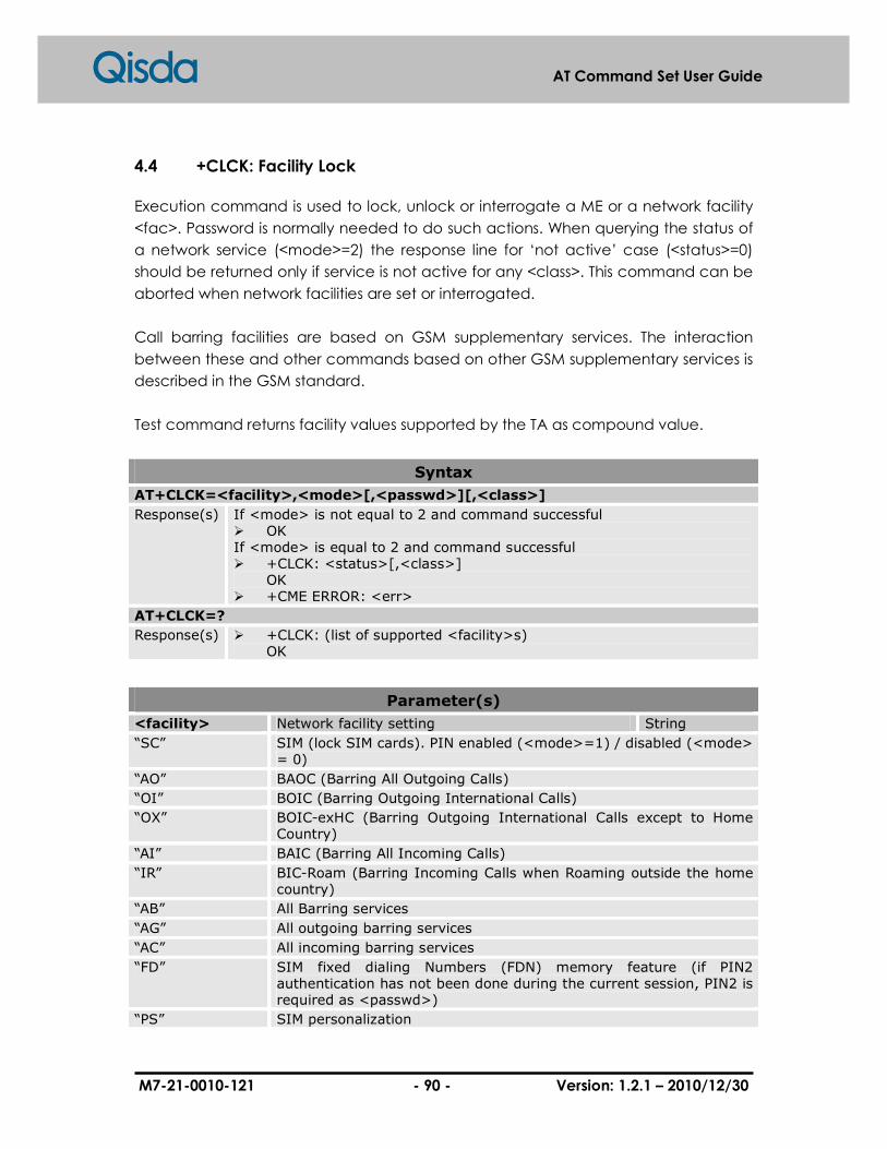
M7-21-0010-121 - 90 - Version: 1.2.1 – 2010/12/30
AT Command Set User Guide
4.4 +CLCK: Facility Lock
Execution command is used to lock, unlock or interrogate a ME or a network facility
<fac>. Password is normally needed to do such actions. When querying the status of
a network service (<mode>=2) the response line for ‘not active’ case (<status>=0)
should be returned only if service is not active for any <class>. This command can be
aborted when network facilities are set or interrogated.
Call barring facilities are based on GSM supplementary services. The interaction
between these and other commands based on other GSM supplementary services is
described in the GSM standard.
Test command returns facility values supported by the TA as compound value.
Syntax
AT+CLCK=<facility>,<mode>[,<passwd>][,<class>]
Response(s) If <mode> is not equal to 2 and command successful � OK If <mode> is equal to 2 and command successful � +CLCK: <status>[,<class>]
OK � +CME ERROR: <err>
AT+CLCK=?
Response(s) � +CLCK: (list of supported <facility>s) OK
Parameter(s)
<facility> Network facility setting String
“SC” SIM (lock SIM cards). PIN enabled (<mode>=1) / disabled (<mode> = 0)
“AO” BAOC (Barring All Outgoing Calls)
“OI” BOIC (Barring Outgoing International Calls)
“OX” BOIC-exHC (Barring Outgoing International Calls except to Home Country)
“AI” BAIC (Barring All Incoming Calls)
“IR” BIC-Roam (Barring Incoming Calls when Roaming outside the home country)
“AB” All Barring services
“AG” All outgoing barring services
“AC” All incoming barring services
“FD” SIM fixed dialing Numbers (FDN) memory feature (if PIN2 authentication has not been done during the current session, PIN2 is required as <passwd>)
“PS” SIM personalization

M7-21-0010-121 - 91 - Version: 1.2.1 – 2010/12/30
AT Command Set User Guide
“PN” Network personalization of the ME
“PU” Network subset personalization of the ME
“PP” Service provider personalization of the ME
“PC” Corporate personalization of the ME
“PF” Personalization on first inserted SIM
<mode> Lock mode Numeric
0 Unlock
1 Lock
2 Query status
<status> Lock status Numeric
0 Not active
1 Active
<passwd> Indicate PIN or network password String
<class> Sum of some of the follow classes. Value range: 1-255 (default 7)
Numeric
1 Voice
2 Data
4 Fax
8 Short message
16 Data circuit sync
32 Data circuit async
64 Dedicated packet access
128 Dedicated PAD access
Example(s)
PIN number control
AT+CLCK=”SC”,1,”1234” OK AT+CLCK=”SC”,0,”1234” OK
1. Enable PIN number with “1234
2. Disable PIN number

M7-21-0010-121 - 92 - Version: 1.2.1 – 2010/12/30
AT Command Set User Guide
4.5 +CPWD: Change password
Action command sets a new password for the facility lock function defined by
command Facility Lock +CLCK.
Syntax
AT+CPWD=<facility>,<oldpwd>,<newpwd>
Response(s) � OK � +CME ERROR: <err>
AT+CPWD=?
Response(s) � +CPWD: list of supported (<facility>,<pwdlength>)s OK
Parameter(s)
<facility> Network facility setting String
“SC” SIM (lock SIM cards). PIN enabled (<mode>=1) / disabled (<mode> = 0)
“AO” BAOC (Barring All Outgoing Calls)
“OI” BOIC (Barring Outgoing International Calls)
“OX” BOIC-exHC (Barring Outgoing International Calls except to Home Country)
“AI” BAIC (Barring All Incoming Calls)
“IR” BIC-Roam (Barring Incoming Calls when Roaming outside the home country)
“AB” All Barring services
“AG” All outgoing barring services
“AC” All incoming barring services
“FD” SIM fixed dialing Numbers (FDN) memory feature (if PIN2 authentication has not been done during the current session, PIN2 is required as <passwd>)
“PS” SIM personalization
“PN” Network personalization of the ME
“PU” Network subset personalization of the ME
“PP” Service provider personalization of the ME
“PC” Corporate personalization of the ME
“PF” Personalization on first inserted SIM
<oldpwd> Old password specified for the facility String
<newpwd> New password String
<pwdlength> Maximum length of the password for the facility Numeric

M7-21-0010-121 - 93 - Version: 1.2.1 – 2010/12/30
AT Command Set User Guide
4.6 +CLIP: Calling line identification presentation
This command enables a called subscriber to get the calling line identity (CLI) of the
calling party when receiving a mobile terminated call.
Syntax
AT+CLIP=[<n>]
Response(s) � OK � +CME ERROR: <err>
AT+CLIP?
Response(s) � +CLIP: <n>,<m> OK
AT+CLIP=?
Response(s) � +CLIP: (list of supported <n>s) OK
Unsolicited Result Codes
� +CLIP: <number>,<type>,,[,<alpha>][,<CLI validity>]
Parameter(s)
<n> Sets /shows the result code presentation status in TA
Numeric
0 Disables
1 Enables
<m> Shows the subscriber CLIP service status in the network
Numeric
0 CLIP not provisioned
1 CLIP provisioned
2 Unknown (e.g. no network, etc.)
<number> Pone number of calling address String
<type> Type of address octet in integer format Numeric
<alpha> String alphanumeric representation of <number> corresponding to the entry found in phonebook
String
<CLI validity> CLI validity Numeric
0 CLI valid
1 CLI has been withheld by the originator.
2 CLI is not available due to inter-working problems or limitations of originating network. <number> shall be an empty string ("") and <type> value will not be significant.

M7-21-0010-121 - 94 - Version: 1.2.1 – 2010/12/30
AT Command Set User Guide
Example(s)
Activate CLI presentation
AT+CLIP=1 OK AT+CLIP? +CLIP: 1, 1 RING +CLIP: “0920123456”,129,””,,”APPLE”,0
1. Enables CLI presentation 2. Query status 3. Incoming call 4. Shows the URC
(AT+CSCS=”IRA”)

M7-21-0010-121 - 95 - Version: 1.2.1 – 2010/12/30
AT Command Set User Guide
4.7 +CLIR: Call line identification restriction
This command allows a calling subscriber to enable or disable the presentation of the
CLI to the called party when a call is creating. Set command overrides the CLIR
subscription (default is restricted or allowed) when temporary mode is provisioned as
a default adjustment for all following outgoing calls. This adjustment can be revoked
by using the opposite command. Read command gives the default adjustment for all
outgoing calls (given in <n>), and also triggers an interrogation of the provision status
of the CLIR service (given in <m>). Test command returns values supported by the TA
as a compound value.
Syntax
AT+CLIR=[<n>]
Response(s) � OK � +CME ERROR: <err>
AT+CLIR?
Response(s) � +CLIR: <n>,<m> OK
AT+CLIR=?
Response(s) � +CRC: (list of supported <n>s) OK
Parameter(s)
<n> Sets the adjustment for outgoing call Numeric
0 Presentation indicator is used according to CLIR service.
1 CLIR invocation
2 CLIR suppression
<m> Shows the subscriber CLIR service status in the network
Numeric
0 CLIR not provisioned
1 CLIR provisioned
2 Unknown (e.g. no network, etc.)
3 CLIR temporary mode presentation restricted
4 CLIR temporary mode presentation allowed

M7-21-0010-121 - 96 - Version: 1.2.1 – 2010/12/30
AT Command Set User Guide
4.8 +COLP: Connection line identification presentation
This command enables a calling subscriber to get the connected line identity (COL)
of the called party after setting up a mobile call has been created. The command
enables or disables the presentation of the COL at the TE. It has no effect on the
execution of the supplementary service COLR in the network. This command is useful
for call forwarding of the connected line.
When it is enabled (and called subscriber allows),
+COLP: <number>, <type>[, <subaddr>, <satype>[, <alpha>]] intermediate result
code is returned from TA to TE before any +CR or V.25ter response. It is manufacturer
specific if this response is used base on normal voice call is established.
Read command gives the status of <n>, and also triggers an interrogation of the
provision status of the COLP service (given in <m>).
Syntax
AT+COLP=[<n>]
Response(s) � OK � +CME ERROR: <err>
AT+COLP?
Response(s) � +COLP: <n>,<m> OK
AT+COLP=?
Response(s) � +COLP: (list of supported <n>s) OK
Unsolicited Result Codes
� +COLP: <number>,<type>[,<subaddr>,<satype>[,<alpha>]]
Parameter(s)
<n> Parameter sets/shows the result code presentation status in the TA
Numeric
0 Disable
1 Enable
<m> Parameter shows the subscriber COLP service status in the network
Numeric
0 COLP not provisioned
1 COLP provisioned
2 Unknown (e.g. no network, etc.)
<number> String phone number of connected address in format specified by <type>
String
<type> Type of address octet in integer format Numeric
<subaddr> Subaddress of format specified by <satype> String
M7-21-0010-121 - 97 - Version: 1.2.1 – 2010/12/30
AT Command Set User Guide
<satype> Type of subaddress octet in integer format Numeric
<alpha> Optional alphanumeric string String
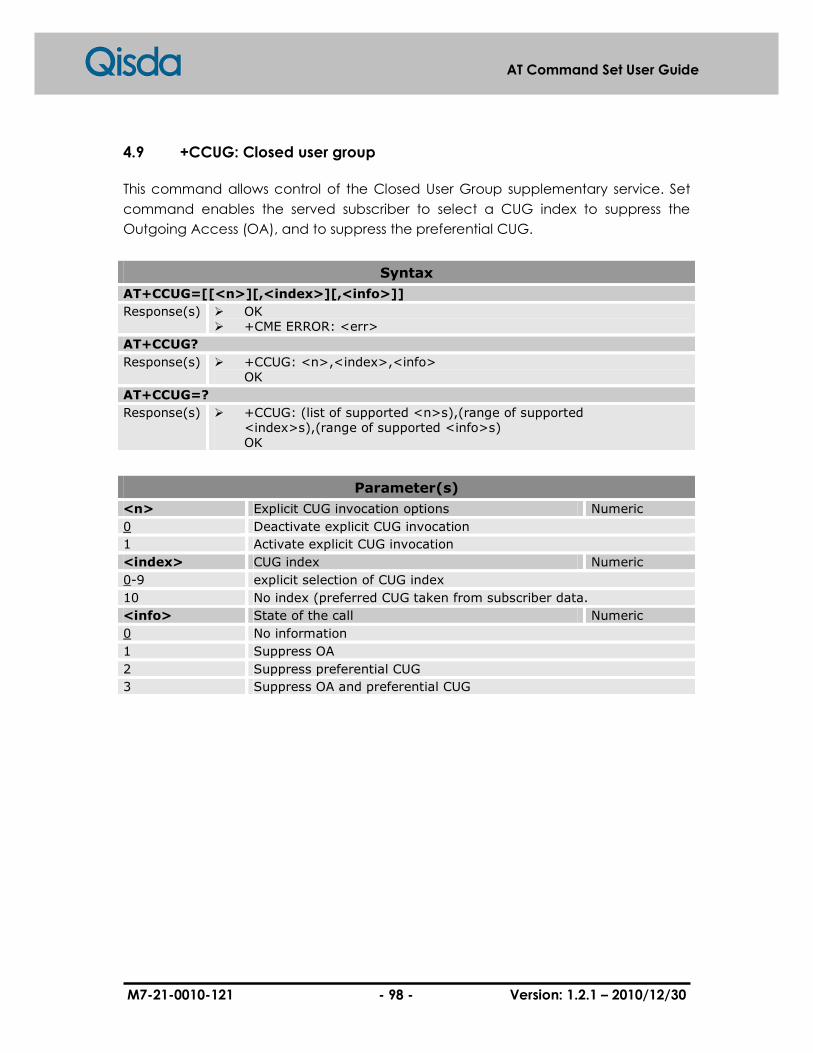
M7-21-0010-121 - 98 - Version: 1.2.1 – 2010/12/30
AT Command Set User Guide
4.9 +CCUG: Closed user group
This command allows control of the Closed User Group supplementary service. Set
command enables the served subscriber to select a CUG index to suppress the
Outgoing Access (OA), and to suppress the preferential CUG.
Syntax
AT+CCUG=[[<n>][,<index>][,<info>]]
Response(s) � OK � +CME ERROR: <err>
AT+CCUG?
Response(s) � +CCUG: <n>,<index>,<info> OK
AT+CCUG=?
Response(s) � +CCUG: (list of supported <n>s),(range of supported <index>s),(range of supported <info>s) OK
Parameter(s)
<n> Explicit CUG invocation options Numeric
0 Deactivate explicit CUG invocation
1 Activate explicit CUG invocation
<index> CUG index Numeric
0-9 explicit selection of CUG index
10 No index (preferred CUG taken from subscriber data.
<info> State of the call Numeric
0 No information
1 Suppress OA
2 Suppress preferential CUG
3 Suppress OA and preferential CUG

M7-21-0010-121 - 99 - Version: 1.2.1 – 2010/12/30
AT Command Set User Guide
4.10 +CCFC: Call forwarding service
This command allows control of the call forwarding supplementary service.
Registration, erasure, activation, deactivation, and status query are supported.
Syntax
AT+CCFC =<reason>,<mode>[,<number>[,<type>[,<class>[,<subaddr>[, <satype>[,<time>]]]]]]
Response(s) If <mode> is not equal to 2 and command successful � OK If <mode> is equal to 2, <reason> is not equal to 2 and command successful � +CCFC: <status>,<class>[,<number>,<type>]
OK If <mode> is equal to 2, <reason> is equal to 2 and command successful � +CCFC: <status>,<class>[,<number>,<type>,<time>]
OK � +CME ERROR: <err>
AT+CCFC=?
Response(s) � +CCFC: (list of supported <reason>s) OK
Parameter(s)
<reason> Reason for call forwarding Numeric
0 Unconditional
1 Mobile busy
2 No reply
3 Not reachable
4 All call forwarding (set reason 0,1,2,3 simultaneously)
5 All conditional call forwarding (set reason 0,1,2,3 simultaneously)
<mode> Network operation to be performed for Supplementary service "call forwarding"
Numeric
0 Disable
1 Enable
2 Query Status
3 Registration
4 Erasure
<class> Sum of bearer service code Numeric
1 Voice (telephony)
2 Data (refers to all bearer services; with <mode>=2 this may refer only to some bearer service if TA does not support values 16,32,64 and 128)
4 Fax (facsimile services)
8 Short message service
16 Data circuit sync
32 Data circuit async

M7-21-0010-121 - 100 - Version: 1.2.1 – 2010/12/30
AT Command Set User Guide
64 Dedicated packet access
128 Dedicated PAD access
<number> String phone number of connected address in format specified by <type>
String
<type> Type of address octet in integer format Numeric
<subaddr> Subaddress of format specified by <satype> String
<satype> Type of subaddress octet in integer format Numeric
<time> Time to wait before call is forwarded Numeric
1-30 Range from 1 second to 30 seconds, Default value is 20
<status> Call Forwarding status Numeric
0 Not activate
1 Activate
Example(s)
Registration
AT+CCFC=0,3,” 0911222333” OK
Before enable, disable, and erasure, you should register the SS service. Register unconditional forwarding to “0911222333” and activated the service. It doesn’t means that the SS service is registered successfully. You should query the status to confirm the result.
Query
AT+CCFC=0,2 +CCFC: 1,1,"886911222333",145 OK AT+CCFC=4,2 ERROR AT+CCFC=5,2 ERROR
Query reason 4,5 is not supported
Erasure
AT+CCFC=0,4 OK AT+CCFC=0,2 +CCFC: 0,7 OK
1. Erase call forwarding service of all classes.

M7-21-0010-121 - 101 - Version: 1.2.1 – 2010/12/30
AT Command Set User Guide
4.11 +CCWA: Call waiting service
This command allows control of the Call Waiting supplementary service. Activation,
deactivation and status query are supported. When querying the status of a network
service (<mode>=2) the response line for ‘not active’ case (<status>=0) should be
returned only if services are not active for any <class>. Parameter <n> is used to
disable/enable the presentation of an unsolicited result code +CCWA: <number>,
<type>, <class>,[<alpha>][,<CLI validity>] to the TE when call waiting service is
enabled.
Syntax
AT+CCWA=[<n>[,<mode>[,<class>]]]
Response(s) If <mode> is not equal to 2 and command successful � OK If <mode> is equal to 2 and command successful � +CCWA: <status>,<class>
OK � +CME ERROR: <err>
AT+CCWA?
Response(s) � +CCWA: <n> OK
AT+CCWA=?
Response(s) � +CCWA: (list of supported <n>s) OK
Unsolicited Result Codes
� +CCWA: <number>,<type>,<class>,<CLI validity>
Parameter(s)
<n> Sets/shows the unsolicited result code presentation status in the TA
Numeric
0 Disable
1 Enable
<mode> Network operation to be performed for Supplementary service call waiting
Numeric
0 Disable
1 Enable
2 Query status
<status> CCWA status Numeric
0 Not active
1 Active
<class> Sum of integers each representing a class of information
Numeric
1 Voice
2 Data (refers to all bearer services; with <mode>=2 this may refer only

M7-21-0010-121 - 102 - Version: 1.2.1 – 2010/12/30
AT Command Set User Guide
to some bearer service if TA does not support values 16,32,64 and 128)
4 Fax (facsimile services)
8 Short message service
16 Data circuit sync
32 Data circuit async
64 Dedicated packet access
128 Dedicated PAD access
<number> Phone number of calling address in format specified by <type>
String
<type> Type of address octet in integer format Numeric
<CLI validity> CLI validity Numeric
0 CLI valid
1 CLI has been withheld by the originator.
2 CLI is not available due to inter-working problems or limitations of originating network.
Example(s)
Query status
AT+CCWA=1,2 +CCWA: 1,1 OK
Class 1 is activated.
Deactivate call waiting service of class 1
AT+CCWA=1,0,1 OK AT+CCWA=1,2 +CCWA: 0,7 OK
Activate call waiting service of class 1
AT+CCWA=1,1,1 OK AT+CCWA=1,2 +CCWA: 1,1 OK
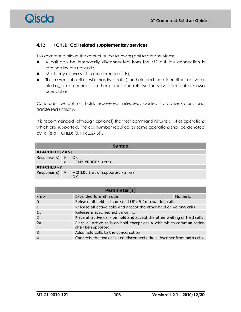
M7-21-0010-121 - 103 - Version: 1.2.1 – 2010/12/30
AT Command Set User Guide
4.12 +CHLD: Call related supplementary services
This command allows the control of the following call related services:
� A call can be temporarily disconnected from the ME but the connection is
retained by the network;
� Multiparty conversation (conference calls);
� The served subscriber who has two calls (one held and the other either active or
alerting) can connect to other parties and release the served subscriber’s own
connection.
Calls can be put on hold, recovered, released, added to conversation, and
transferred similarly.
It is recommended (although optional) that test command returns a list of operations
which are supported. The call number required by some operations shall be denoted
by "x" (e.g. +CHLD: (0,1,1x,2,2x,3)).
Syntax
AT+CHLD=[<n>]
Response(s) � OK � +CME ERROR: <err>
AT+CHLD=?
Response(s) � +CHLD: (list of supported <n>s) OK
Parameter(s)
<n> Extended format mode Numeric
0 Release all held calls or send UDUB for a waiting call.
1 Release all active calls and accept the other held or waiting calls.
1x Release a specified active call x.
2 Place all active calls on hold and accept the other waiting or held calls.
2x Place all active calls on hold except call x with which communication shall be supported.
3 Adds held calls to the conversation.
4 Connects the two calls and disconnects the subscriber from both calls.
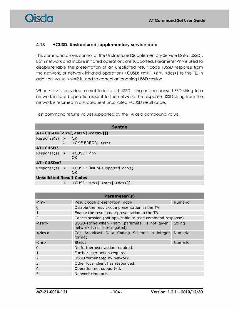
M7-21-0010-121 - 104 - Version: 1.2.1 – 2010/12/30
AT Command Set User Guide
4.13 +CUSD: Unstructured supplementary service data
This command allows control of the Unstructured Supplementary Service Data (USSD).
Both network and mobile initiated operations are supported. Parameter <n> is used to
disable/enable the presentation of an unsolicited result code (USSD response from
the network, or network initiated operation) +CUSD: <m>[, <str>, <dcs>] to the TE. In
addition, value <n>=2 is used to cancel an ongoing USSD session.
When <str> is provided, a mobile initiated USSD-string or a response USSD-string to a
network initiated operation is sent to the network. The response USSD-string from the
network is returned in a subsequent unsolicited +CUSD result code.
Test command returns values supported by the TA as a compound value.
Syntax
AT+CUSD=[<n>[,<str>[,<dcs>]]]
Response(s) � OK � +CME ERROR: <err>
AT+CUSD?
Response(s) � +CUSD: <n> OK
AT+CUSD=?
Response(s) � +CUSD: (list of supported <n>s) OK
Unsolicited Result Codes
� +CUSD: <m>[,<str>[,<dcs>]]
Parameter(s)
<n> Result code presentation mode Numeric
0 Disable the result code presentation in the TA
1 Enable the result code presentation in the TA
2 Cancel session (not applicable to read command response)
<str> USSD-string(when <str> parameter is not given, network is not interrogated)
String
<dcs> Cell Broadcast Data Coding Scheme in integer format
Numeric
<m> Status Numeric
0 No further user action required.
1 Further user action required.
2 USSD terminated by network.
3 Other local client has responded.
4 Operation not supported.
5 Network time out.

M7-21-0010-121 - 105 - Version: 1.2.1 – 2010/12/30
AT Command Set User Guide
4.14 +CAOC: Advice of charge
This refers to Advice of Charge supplementary service that enables subscriber to get
information about the cost of calls. With <mode>=0, the execute command returns
the current call meter value from the ME.
The command is also possible to enable an unsolicited event reporting of the CCM
information. The unsolicited result code +CCCM: <ccm> is sent every (no more than)
10 seconds when the CCM value is changed. Deactivation of the unsolicited event
reporting is made with the same command.
The Read command indicates whether the unsolicited reporting is activated or not.
Read command is available when the unsolicited result code is supported.
Syntax
AT+CAOC=[<mode>]
Response(s) � [+CAOC: <ccm>] OK
� +CME ERROR: <err>
AT+CAOC?
Response(s) � +CAOC: <mode> OK
AT+CAOC=?
Response(s) � +CAOC: (list of supported <mode>s) OK
Parameter(s)
<mode> Setting mode Numeric
0 Query CCM value
1 Deactivate the unsolicited reporting of CCM value
2 Activate the unsolicited reporting of CCM value
<ccm> Three bytes of the current call meter value in hexadecimal format.
String

M7-21-0010-121 - 106 - Version: 1.2.1 – 2010/12/30
AT Command Set User Guide
4.15 +CSSN: Supplementary service notifications
This command refers to supplementary service related network initiated notifications.
The set command enables/disables the presentation of notification result codes from
TA to TE.
When <n>=1 and a supplementary service notification is received after a mobile call
setup is created, intermediate result code +CSSI: <code1>[,<index>] is sent to TE
before any other MO call setup result codes which is described in related document
of V.25ter. When several different <code1>s are received from the network, each of
them shall have its own +CSSI result code.
When <m>=1 and a supplementary service notification is received during a mobile
terminated call setup or during a call, or when a forward check supplementary
service notification is received, unsolicited result code +CSSU:
<code2>[,<index>[,<number>,<type>]]] is sent to TE. In case of MT call setup, result
code is sent after every +CLIP result code (refer command "Calling line identification
presentation +CLIP") and when several different <code2>s are received from the
network, each of them shall have its own +CSSU result code.
Test command returns values supported by the TA as a compound value.
Syntax
AT+CSSN=[<n>[,<m>]]
Response(s) � OK � +CME ERROR: <err>
AT+CSSN?
Response(s) � +CSSN: <n>,<m> OK
AT+CSSN=?
Response(s) � +CSSN: (list of supported <n>s), (list of supported <m>s) OK
Unsolicited Result Codes
� +CSSI: <code1>[,<index>]
� +CSSU: <code2>[,<index>[,<number>[,<type>]]]
Parameter(s)
<n> Parameter sets/shows the +CSSI result code presentation status
Numeric
0 Disable
1 Enable
<m> Parameter sets/shows the +CSSU result code Numeric

M7-21-0010-121 - 107 - Version: 1.2.1 – 2010/12/30
AT Command Set User Guide
presentation status
0 Disable
1 Enable
<code1> +CSSI unsolicited result code content Numeric
0 Unconditional call forwarding is active
1 Some of the conditional call forwarding are active
2 Call has been forwarded
3 Call is waiting
4 This is a CUG call
5 Outgoing calls are barred
6 Incoming calls are barred
7 CLIR suppression rejected
8 Call has been deflected
<index> CUG index Numeric
0-9 explicit selection of CUG index
10 No index (preferred CUG taken from subscriber data.
<code2> +CSSU unsolicited result code content Numeric
0 This is a forwarded call
1 This is a CUG call
2 Call has been put on hold
3 Call has been retrieved
4 Multiparty call entered
5 Call on hold has been released
6 Forward check SS message received
7 Call is being connected with the remote party in alerting state in explicit call transfer operation
8 Call has been connected with the other remote party I explicit call transfer operation
9 This is a deflected call
10 Additional incoming call forwarded
<number> Phone number String
<type> Type of address octet Numeric
Example(s)
Enables service notifications
AT+CSSN=1,1 OK atd0937135753; OK +CSSI: 1 NO CARRIER OK
1. Enable both service notifications
2. Call to one phone
number which is “call forward” to another phone
3. CSSI URC information
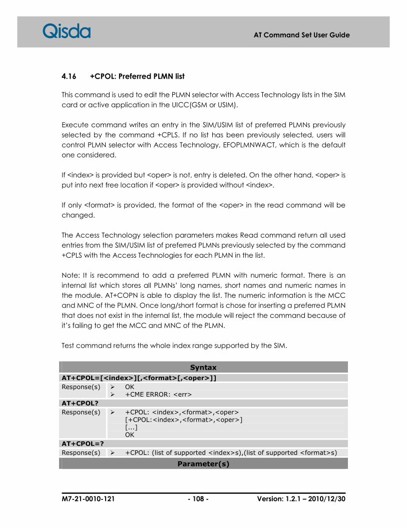
M7-21-0010-121 - 108 - Version: 1.2.1 – 2010/12/30
AT Command Set User Guide
4.16 +CPOL: Preferred PLMN list
This command is used to edit the PLMN selector with Access Technology lists in the SIM
card or active application in the UICC(GSM or USIM).
Execute command writes an entry in the SIM/USIM list of preferred PLMNs previously
selected by the command +CPLS. If no list has been previously selected, users will
control PLMN selector with Access Technology, EFOPLMNWACT, which is the default
one considered.
If <index> is provided but <oper> is not, entry is deleted. On the other hand, <oper> is
put into next free location if <oper> is provided without <index>.
If only <format> is provided, the format of the <oper> in the read command will be
changed.
The Access Technology selection parameters makes Read command return all used
entries from the SIM/USIM list of preferred PLMNs previously selected by the command
+CPLS with the Access Technologies for each PLMN in the list.
Note: It is recommend to add a preferred PLMN with numeric format. There is an
internal list which stores all PLMNs’ long names, short names and numeric names in
the module. AT+COPN is able to display the list. The numeric information is the MCC
and MNC of the PLMN. Once long/short format is chose for inserting a preferred PLMN
that does not exist in the internal list, the module will reject the command because of
it’s failing to get the MCC and MNC of the PLMN.
Test command returns the whole index range supported by the SIM.
Syntax
AT+CPOL=[<index>][,<format>[,<oper>]]
Response(s) � OK � +CME ERROR: <err>
AT+CPOL?
Response(s) � +CPOL: <index>,<format>,<oper> [+CPOL:<index>,<format>,<oper>] [...] OK
AT+CPOL=?
Response(s) � +CPOL: (list of supported <index>s),(list of supported <format>s)
Parameter(s)

M7-21-0010-121 - 109 - Version: 1.2.1 – 2010/12/30
AT Command Set User Guide
<index> The order number of operator in the SIM/USIM preferred operator list. (range depended on SIM)
Numeric
<format> Format of network operator representation. Numeric
0 Long format alphanumeric <oper>
1 Short format alphanumeric <oper>
2 Numeric <oper>
<oper> Operator name String
Example(s)
Preferred PLMN list
AT+CPOL=? +CPOL: (1-8), (0-2) OK AT+CPOL? +CPOL:1,2,”46697” OK
1. Get parameter. 2. Query current value.

M7-21-0010-121 - 110 - Version: 1.2.1 – 2010/12/30
AT Command Set User Guide
4.17 +CLCC: List current calls
To return a list of current calls of ME. If command succeeds but no calls are available,
no information response is sent to TE.
Syntax
AT+CLCC
Response(s) � [+CLCC: <id>, <dir>, <state>, <mode>, <mpty>[, <number>, <type>[, <alpha>]]] [+CLCC: <id>, <dir>, <state>, <mode>, <mpty>[, <number>, <type>[, <alpha>]]] […] OK
� +CME ERROR: <err>
AT+CLCC=?
Response(s) � OK
Parameter(s)
<id> Call identification number Numeric
<dir> Call direction Numeric
0 Mobile originated (MO) call
1 Mobile terminated (MT) call
<state> state of the call Numeric
0 Active
1 Held
2 Dialing (MO call)
3 Alerting (MO call)
4 Incoming (MT call)
5 Waiting (MT call)
<mode> bearer/teleservice Numeric
0 Voice
1 Data
2 Fax
3 Voice followed by data, voice mode
4 Alternating voice/data, voice mode
5 Alternating voice/fax, voice mode
6 Voice followed by data, data mode
7 Alternating voice/data, data mode
8 Alternating voice/fax, fax mode
9 Unknown
<mpty> Multiparty (conference) call parties Numeric
0 Call is not one of multiparty (conference) call parties
1 Call is one of multiparty (conference) call parties

M7-21-0010-121 - 111 - Version: 1.2.1 – 2010/12/30
AT Command Set User Guide
<number> Phone number in format specified by <type> String
<type> Type of address octet Numeric
129 Dialing string without international access code “+”.
145 Dialing string includes international access code character “+”.
<alpha> Alphanumeric representation of <number> corresponding to the entry found in phonebook; used character set should be the one selected with command +CSCS
String
Example(s)
List current calls
ATD0952123456; OK AT+CLCC +CLCC: 1,0,0,0,0,"0952123456",129,"aa"
1. Dial number. 2. List current call.

M7-21-0010-121 - 112 - Version: 1.2.1 – 2010/12/30
AT Command Set User Guide
4.18 +COPN: Read operator names
Execute command returns the list of operators’ names from the ME. Each operator
code<numeric> that has an alphanumeric equivalent <alpha> in the ME memory
shall be returned.
Syntax
AT+COPN
Response(s) � +COPN: <numeric>, <alpha> [+COPN: <numeric>, <alpha>] […] OK
� +CME ERROR: <err>
AT+COPN=?
Response(s) � OK
Parameter(s)
<numeric> Operator in numeric format(see +COPS) String
<alpha> Operator in long alphanumeric format(see +COPS) String
Example(s)
Read operator names
AT+COPN +COPN: "00131","Test Network" +COPN: "546559","Test Net 222" +COPN: "56231","A1" +COPN: "56263","A max." …… OK
1. Get operator’s name.

M7-21-0010-121 - 113 - Version: 1.2.1 – 2010/12/30
AT Command Set User Guide
4.19 $GNC: Get neighbor cells
This command is used to get the identity of the neighbor cells. The maximum
values of neighbor cells is up to 6.
Syntax
AT$GNC?
Response(s) � list of possible <ncid>s OK
Parameter(s)
<ncid> Two byte cell ID in hexadecimal format String
Example(s)
Get Neighbor Cells
AT$GNC? 4ecc,3c7d,959f,763a,8a9d,0 OK
1. Get cell information. 2. Query current value.

M7-21-0010-121 - 114 - Version: 1.2.1 – 2010/12/30
AT Command Set User Guide
4.20 %BAND: Dynamic multiband
This command is used to manage which radio bands are scanned.
Syntax
AT%BAND=<mode>[,<band>]
Response(s) � OK � +CME ERROR: <err>
AT%BAND?
Response(s) � %BAND: <mode>[,<band>] OK
AT%BAND =?
Response(s) � %BAND: (list of supported <mode>s), (list of supported <band>s) OK
Parameter(s)
<mode> Set the radio band switch mode Numeric
0 Automatic
1 Manual
<band> Is a sum of integers each representing a band Numeric
1 GSM 900
2 DCS 1800
4 PCS 1900
8 E-GSM
16 GSM 850
Example(s)
Define PDP context
AT%BAND=1,15 set MS to scan 900/1800/1900. For modules-based products, MS will re-register to the network automatically.
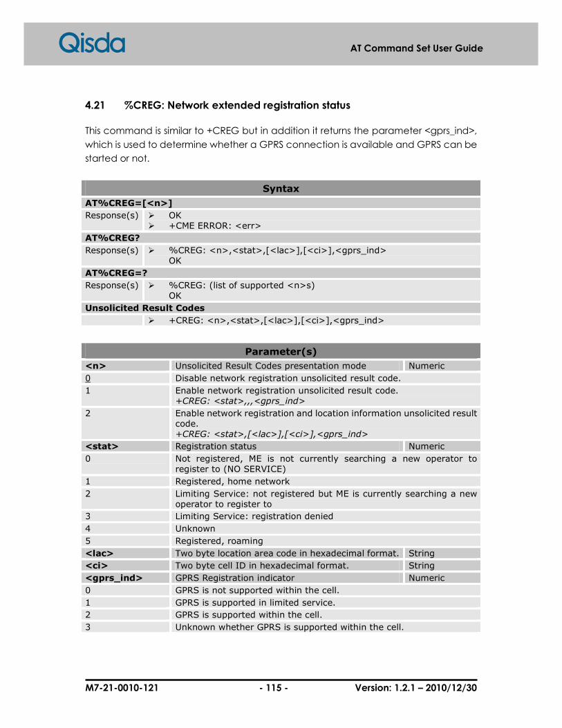
M7-21-0010-121 - 115 - Version: 1.2.1 – 2010/12/30
AT Command Set User Guide
4.21 %CREG: Network extended registration status
This command is similar to +CREG but in addition it returns the parameter <gprs_ind>,
which is used to determine whether a GPRS connection is available and GPRS can be
started or not.
Syntax
AT%CREG=[<n>]
Response(s) � OK � +CME ERROR: <err>
AT%CREG?
Response(s) � %CREG: <n>,<stat>,[<lac>],[<ci>],<gprs_ind> OK
AT%CREG=?
Response(s) � %CREG: (list of supported <n>s) OK
Unsolicited Result Codes
� +CREG: <n>,<stat>,[<lac>],[<ci>],<gprs_ind>
Parameter(s)
<n> Unsolicited Result Codes presentation mode Numeric
0 Disable network registration unsolicited result code.
1 Enable network registration unsolicited result code. +CREG: <stat>,,,<gprs_ind>
2 Enable network registration and location information unsolicited result code. +CREG: <stat>,[<lac>],[<ci>],<gprs_ind>
<stat> Registration status Numeric
0 Not registered, ME is not currently searching a new operator to register to (NO SERVICE)
1 Registered, home network
2 Limiting Service: not registered but ME is currently searching a new operator to register to
3 Limiting Service: registration denied
4 Unknown
5 Registered, roaming
<lac> Two byte location area code in hexadecimal format. String
<ci> Two byte cell ID in hexadecimal format. String
<gprs_ind> GPRS Registration indicator Numeric
0 GPRS is not supported within the cell.
1 GPRS is supported in limited service.
2 GPRS is supported within the cell.
3 Unknown whether GPRS is supported within the cell.

M7-21-0010-121 - 116 - Version: 1.2.1 – 2010/12/30
AT Command Set User Guide
5 Mobile Equipment Control and Status Commands
5.1 +CPAS: Phone activity status
Execution command returns the activity status <pas> of the ME. It can be used to
interrogate the ME before requesting action from the phone.
Syntax
AT+CPAS
Response(s) � +CPAS: <pas> OK
� +CME ERROR: <err>
AT+CPAS=?
Response(s) � +CPAS: (list of supported <pas>s) OK
Parameter(s)
<pas> Phone activity status Numeric
0 Ready.
1 Unavailable.
2 Unknown.
3 Ringing.
4 Call in progress.
5 Asleep.
Example(s)
Test phone activity status
AT+CPAS=? +CPAS: (0-5) OK
Query phone activity status
AT+CPAS +CPAS: 0 OK

M7-21-0010-121 - 117 - Version: 1.2.1 – 2010/12/30
AT Command Set User Guide
5.2 +CFUN: Set phone functionality
Set command selects the level of functionality <fun> in the ME. Level “full
functionality” is where the highest level of power is drawn; on the other hand, level
“Minimum functionality” is where minimum power is drawn. Level of functionality
between these may also be specified by manufacturers. When it is supported by
manufacturers, ME resetting with <rst> parameter may be utilized.
Syntax
AT+CFUN=<fun>[,<rst>]
Response(s) � OK � +CME ERROR: <err>
AT+CFUN?
Response(s) � +CFUN: <fun> OK
AT+CFUN=?
Response(s) � +CFUN: (list of supported <fun>s),(list of supported <rst>s) OK
Parameter(s)
<fun> Numeric
0 Minimum functionality.
1 Full functionality.
4 Disable phone both transmit and receive RF circuits.
<rst> Numeric
0 Do not reset the ME before setting it to <fun> power level.
1 ME resets and restarts to full functionality.

M7-21-0010-121 - 118 - Version: 1.2.1 – 2010/12/30
AT Command Set User Guide
5.3 $SRN: Facility status notification
This command is used to notify the ready state.
Set command controls the presentation of an URC code $SRN: 1 when <n>=1.
Syntax
AT$SRN=<n>
Response(s) � OK � +CME ERROR: <err>
AT$SRN?
Response(s) � $SRN: <n> OK
AT$SRN =?
Response(s) � $SRN: (list of supported <n>s) OK
Unsolicited Result Codes
� $SRN: <stat>
Parameter(s)
<fun> Numeric
0 Disable facility status unsolicited result code.
1 Enable facility status unsolicited result code.
<stat> Numeric
1 Facility status is ready.
Example(s)
Enable facility status unsolicited result code
AT$SRN=1 OK AT+CFUN=1 OK (When the SMS and Phb are ready) $SRN: 1
1. Enable 2. Active the SIM module 3. Facility status is ready

M7-21-0010-121 - 119 - Version: 1.2.1 – 2010/12/30
AT Command Set User Guide
5.4 +CPIN: Enter PIN
Set command sends the MS a password that is necessary before it can be operated
for only SIM PIN. If no PIN request is pending, no action is taken. If SIM is useless or SIM is
not inserted, an error message +CME ERROR is returned to the TE.
Read command returns an alphanumeric string indicating whether some password is
required or not.
Syntax
AT+CPIN=<pin>[,<newpin>]
Response(s) � OK � +CME ERROR: <err>
AT+CPIN?
Response(s) � +CPIN: <code> OK � +CME ERROR: <err>
Parameter(s)
<pin> A password, usually is PIN String
<newpin> A new password when requested code is PUK String
<code> Requested SIM PIN authentication code String
“READY” ME is not pending for any password.
“SIM PIN” ME is waiting SIM PIN to be given.
“SIM PIN2” ME is waiting SIM PIN2 to be given (this <code> is recommended to be returned only when the last executed command resulted in PIN2 authentication failure (i.e. +CME ERROR: 17); if PIN2 is not entered right after the failure, it is recommended that ME does not block it operation).
“SIM PUK” ME is waiting SIM PUK(=Pin Unblocking Key) to be given after three PIN fail.
“SIM PUK2” ME is waiting SIM PUK2 to be given (this <code> is recommended to be returned only when the last executed command resulted in PUK2 authentication failure (i.e. +CME ERROR: 18); if PUK2 and new PIN2are not entered right after the failure, it is recommended that ME does not block it operation).
Example(s)
Power on (1) (CHV1 is disabled, SIM is ready)
AT+CPIN? +CPIN: READY
Power on (1) (SIM not inserted)
AT+CMEE=2 OK

M7-21-0010-121 - 120 - Version: 1.2.1 – 2010/12/30
AT Command Set User Guide
AT+CPIN? +CME ERROR: SIM not inserted

M7-21-0010-121 - 121 - Version: 1.2.1 – 2010/12/30
AT Command Set User Guide
5.5 +CSQ: Signal quality
Execution command returns received signal strength indication <rssi> and channel bit
error rate <ber> from the MS.
Test command returns values supported by the MS as compound values.
Only support continuous unsolicited response.
Syntax
AT+CSQ
Response(s) � +CSQ: <rssi>,<ber> OK � +CME ERROR: <err>
AT+CSQ=?
Response(s) � +CSQ: (list of supported <rssi>s), (list of supported <ber>s) OK
Parameter(s)
<rssi> RSSI value, signal strength Numeric
0 -113dBm or less
1 -111dBm
2-30 -109dBm ~ -53dBm
31 -51dBm or greater
99 Not known or not detectable.
<ber> Bit error rate Numeric
0-7 RXQUAL values in the table in GSM 05.08.
99 Unknown or not detectable.
Example(s)
Query current signal quality
AT+CSQ +CSQ: 31,99 OK
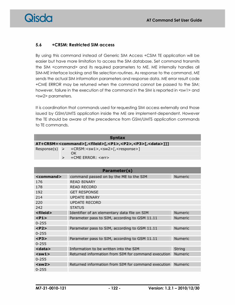
M7-21-0010-121 - 122 - Version: 1.2.1 – 2010/12/30
AT Command Set User Guide
5.6 +CRSM: Restricted SIM access
By using this command instead of Generic SIM Access +CSIM TE application will be
easier but have more limitation to access the SIM database. Set command transmits
the SIM <command> and its required parameters to ME. ME internally handles all
SIM-ME interface locking and file selection routines. As response to the command, ME
sends the actual SIM information parameters and response data. ME error result code
+CME ERROR may be returned when the command cannot be passed to the SIM;
however, failure in the execution of the command in the SIM is reported in <sw1> and
<sw2> parameters.
It is coordination that commands used for requesting SIM access externally and those
issued by GSM/UMTS application inside the ME are implement-dependent. However
the TE should be aware of the precedence from GSM/UMTS application commands
to TE commands.
Syntax
AT+CRSM=<command>[,<fileid>[,<P1>,<P2>,<P3>[,<data>]]]
Response(s) � +CRSM:<sw1>,<sw2>[,<response>] OK � +CME ERROR: <err>
Parameter(s)
<command> command passed on by the ME to the SIM Numeric
176 READ BINARY
178 READ RECORD
192 GET RESPONSE
214 UPDATE BINARY
220 UPDATE RECORD
242 STATUS
<fileid> Identifier of an elementary data file on SIM Numeric
<P1> Parameter pass to SIM, according to GSM 11.11 Numeric
0-255
<P2> Parameter pass to SIM, according to GSM 11.11 Numeric
0-255
<P3> Parameter pass to SIM, according to GSM 11.11 Numeric
0-255
<data> Information to be written into the SIM String
<sw1> Returned information from SIM for command execution Numeric
0-255
<sw2> Returned information from SIM for command execution Numeric
0-255

M7-21-0010-121 - 123 - Version: 1.2.1 – 2010/12/30
AT Command Set User Guide
<response> Response data from SIM for command execution String
Example(s)
AT+CRSM=192,12258,0,0,255 +CRSM: 103,15 OK
Get SIM Card Identification number (ICCID)
AT+CRSM=176,12258,0,0,10 +CRSM: 144,0,98889612040053576639 OK
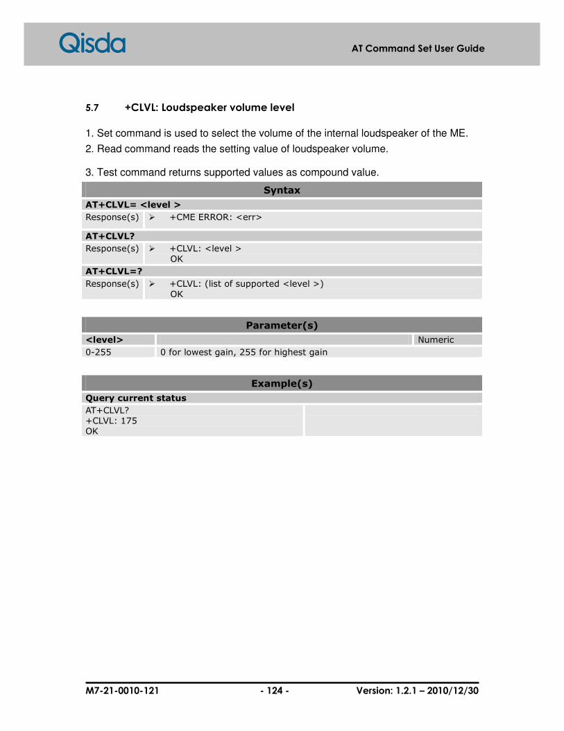
M7-21-0010-121 - 124 - Version: 1.2.1 – 2010/12/30
AT Command Set User Guide
5.7 +CLVL: Loudspeaker volume level
1. Set command is used to select the volume of the internal loudspeaker of the ME.
2. Read command reads the setting value of loudspeaker volume.
3. Test command returns supported values as compound value.
Syntax
AT+CLVL= <level >
Response(s) � +CME ERROR: <err>
AT+CLVL?
Response(s) � +CLVL: <level > OK
AT+CLVL=?
Response(s) � +CLVL: (list of supported <level >) OK
Parameter(s)
<level> Numeric
0-255 0 for lowest gain, 255 for highest gain
Example(s)
Query current status
AT+CLVL? +CLVL: 175 OK

M7-21-0010-121 - 125 - Version: 1.2.1 – 2010/12/30
AT Command Set User Guide
5.8 +CMUT: Mute
This command is used to enable and disable the uplink voice muting during a voice
call.
Syntax
AT+CMUT=<n>
Response(s) � OK � +CME ERROR: <err>
AT+CMUT?
Response(s) � +CMUT: <n> OK
AT+CMUT=?
Response(s) � +CMUT: (list of supported <n >s) OK
Parameter(s)
<n> Must status Numeric
0 MUTE OFF
1 MUTE ON
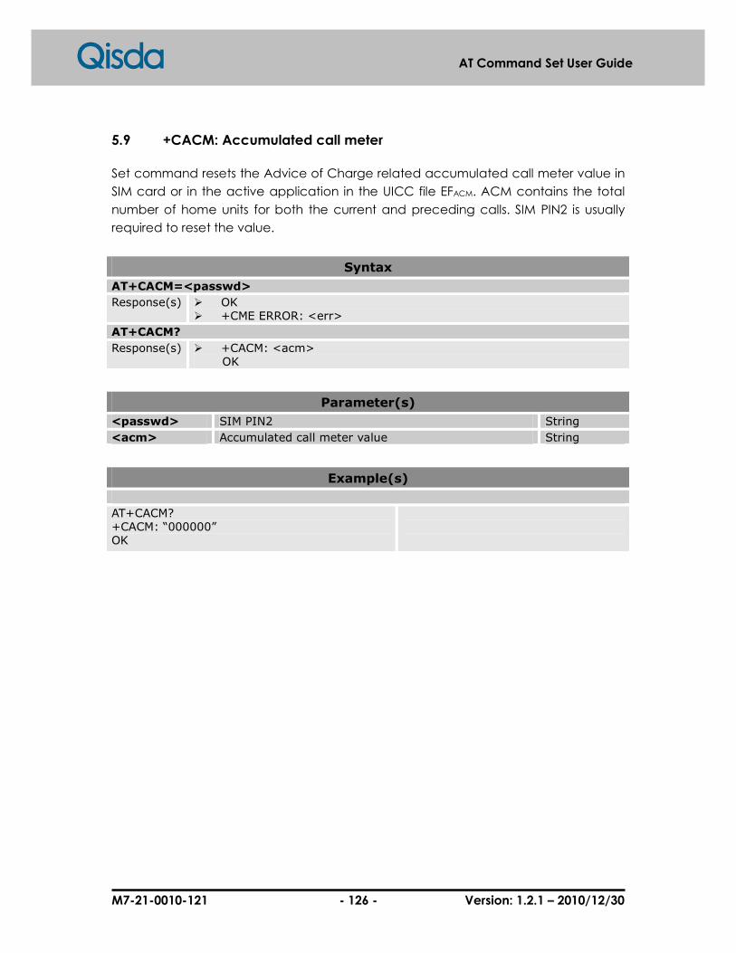
M7-21-0010-121 - 126 - Version: 1.2.1 – 2010/12/30
AT Command Set User Guide
5.9 +CACM: Accumulated call meter
Set command resets the Advice of Charge related accumulated call meter value in
SIM card or in the active application in the UICC file EFACM. ACM contains the total
number of home units for both the current and preceding calls. SIM PIN2 is usually
required to reset the value.
Syntax
AT+CACM=<passwd>
Response(s) � OK � +CME ERROR: <err>
AT+CACM?
Response(s) � +CACM: <acm> OK
Parameter(s)
<passwd> SIM PIN2 String
<acm> Accumulated call meter value String
Example(s)
AT+CACM? +CACM: “000000” OK
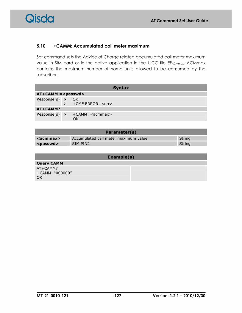
M7-21-0010-121 - 127 - Version: 1.2.1 – 2010/12/30
AT Command Set User Guide
5.10 +CAMM: Accumulated call meter maximum
Set command sets the Advice of Charge related accumulated call meter maximum
value in SIM card or in the active application in the UICC file EFACMmax. ACMmax
contains the maximum number of home units allowed to be consumed by the
subscriber.
Syntax
AT+CAMM =<passwd>
Response(s) � OK � +CME ERROR: <err>
AT+CAMM?
Response(s) � +CAMM: <acmmax> OK
Parameter(s)
<acmmax> Accumulated call meter maximum value String
<passwd> SIM PIN2 String
Example(s)
Query CAMM
AT+CAMM? +CAMM: “000000” OK

M7-21-0010-121 - 128 - Version: 1.2.1 – 2010/12/30
AT Command Set User Guide
5.11 +CPUC: Price per unit and currency table
Set command sets the parameters of Advice of Charge related price per unit and
currency table in SIM card or in the active application in the UICC file EFPUCT.PUCT
information can be used to convert the home units into currency units. SIM PIN2 is
usually required to set the parameters.
Syntax
AT+CPUC=<currency>,<ppu>[,<passed>]
Response(s) � OK � +CME ERROR: <err>
AT+CPUC?
Response(s) � +CPUC: <currency>,<ppu> OK
Parameter(s)
<currency> Three character currency code String
<ppu> Price per unit String
Example(s)
Query CPUC
AT+CPUC? +CPUC: “”,”” OK
Set price per unit and currency element
AT+CPUC=”NT”,”5.00” +CME ERROR: SIM PIN2 required

M7-21-0010-121 - 129 - Version: 1.2.1 – 2010/12/30
AT Command Set User Guide
5.12 +CCWE: Call Meter maximum event
Shortly before the ACM (Accumulated Call Meter) maximum value is reached, an
unsolicited result code +CCWV will be sent if it is enabled by this command. The
warning is issued approximately in the last 30 seconds call time. Warning is also issued
if starting a call before the last 30 seconds call time. If setting is failed in an ME error,
+CME ERROR: <err> is returned.
Read command returns the current setting.
Test command returns supported settings.
Syntax
AT+CCWE=<mode>
Response(s) � OK � +CME ERROR: <err>
AT+CCWE?
Response(s) � +CCWE: <mode> OK
AT+CCWE=?
� +CCWE: (list of supported <mode>s) OK
Unsolicited Result Codes
+CCWE<1> enables the warning event. When ACM approaches the ACM maximum value, event +CCWV will send by TE to ME. � +CCWV After receiving this event, TE should notify user through proper way.
Parameter(s)
<mode> Phone activity status Numeric
0 Disable the call meter warning event.
1 Enable the call meter warning event.
Example(s)
Set call meter maximum event on
AT+CCWE=1 OK

M7-21-0010-121 - 130 - Version: 1.2.1 – 2010/12/30
AT Command Set User Guide
5.13 +CSVM: Set Voice Mail Number
The number for the voice mail server is set through this command. The parameters
<number> and <type> can be ignored if the parameter <mode> is set to 0. If setting is
failed, an ME error +CME ERROR: <err> is returned.
Read command returns the currently selected voice mail number and the status (i.e.
enabled/disabled).
Test command returns supported <mode>s and <type>s.
Syntax
AT+CSVM=<mode>[,<number>[,<type>]]
Response(s) � OK � +CME ERROR: <err>
AT+CSVM?
Response(s) � +CSVM:<mode>,<number>,<type> OK
AT+CSVM=?
� +CSVM: (list of supported <mode>s), (list of supported <type>s) OK
Parameter(s)
<mode> Numeric
0 Disable the voice mail number.
1 Enable the voice mail number.
<number> Character string <0..9,+>, the maximum length of phone number is 40 digits (include prefix ‘+’ if exists)
String
<type> Type of address octet Numeric
129 ISDN/telephony numbering plan, national/international unknown.
145 ISDN/telephony numbering plan, international number.
161 ISDN/telephony numbering plan, national number.
128-255 Other values refer TS 24.008 section 10.5.4.7.
Example(s)
Test command
AT+CSVM=? +CSVM: (0,1),(129,145,161) OK
Query command
AT+CSVM? +CSVM: 1,"188",129 OK

M7-21-0010-121 - 131 - Version: 1.2.1 – 2010/12/30
AT Command Set User Guide
5.14 +CLAC: List all available AT commands
Execution command causes the ME to return one or more lines of AT Commands.
Note: This command only returns the AT commands that are available for the user.
Syntax
AT+CLAC
Response(s) � <AT Command1> <AT Command2> …
OK � +CME ERROR: <err>
Example(s)
List all available commands
AT+CLAC AT+CACM AT+CAMM AT+CAOC …… OK
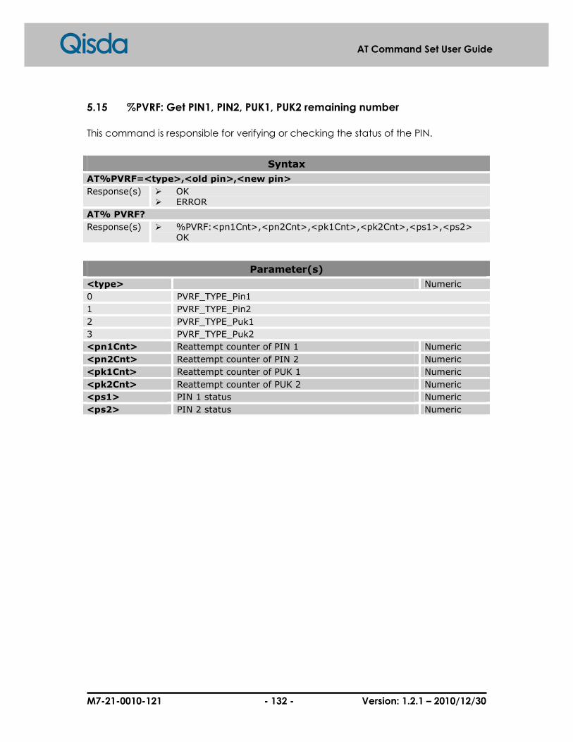
M7-21-0010-121 - 132 - Version: 1.2.1 – 2010/12/30
AT Command Set User Guide
5.15 %PVRF: Get PIN1, PIN2, PUK1, PUK2 remaining number
This command is responsible for verifying or checking the status of the PIN.
Syntax
AT%PVRF=<type>,<old pin>,<new pin>
Response(s) � OK � ERROR
AT% PVRF?
Response(s) � %PVRF:<pn1Cnt>,<pn2Cnt>,<pk1Cnt>,<pk2Cnt>,<ps1>,<ps2> OK
Parameter(s)
<type> Numeric
0 PVRF_TYPE_Pin1
1 PVRF_TYPE_Pin2
2 PVRF_TYPE_Puk1
3 PVRF_TYPE_Puk2
<pn1Cnt> Reattempt counter of PIN 1 Numeric
<pn2Cnt> Reattempt counter of PIN 2 Numeric
<pk1Cnt> Reattempt counter of PUK 1 Numeric
<pk2Cnt> Reattempt counter of PUK 2 Numeric
<ps1> PIN 1 status Numeric
<ps2> PIN 2 status Numeric

M7-21-0010-121 - 133 - Version: 1.2.1 – 2010/12/30
AT Command Set User Guide
5.16 +VTS: DTMF and tone generation
This command allows the transmission of DTMF tones and arbitrary tones (see note).
These tones may be used (for example) when announcing the start of a recording
period. The command is write only. In this profile of commands, this command does
not operate in data or fax modes of operation (+FCLASS=0,1,2-7).
Note: D is used only for dialing.
Syntax
AT+VTS=<tone>
Response(s) � OK � ERROR
AT+VTS=?
Response(s) � (list of supported <tone>s) OK
Parameter(s)
<tone> A single ASCII character in the set 0-9, #,*,A-D. Numeric
0-9, #,*,A-D
Example(s)
Test command
AT+VTS=? +VTS: (0,1,2,3,4,5,6,7,8,9,A,B,C,D,#,*) OK
Query command
AT+VTS=1 OK AT+VTS=9 OK

M7-21-0010-121 - 134 - Version: 1.2.1 – 2010/12/30
AT Command Set User Guide
5.17 +WDTMF: Play DTMF tone
This specific command allows a DTMF tone to be played on the current
speaker. DTMF, gain and duration can be set.
This command is only used to play a DTMF tone. To send a DTMF over the
GSM network, use the +VTS command.
Syntax
AT+WDTMF=<isEnable>[,<dtmf>,<gain>,<duration>]
Response(s) � OK � ERROR
Parameter(s)
<isEnable> Numeric
0 Stop playing
1 Play a DTMF tone
<dtmf> This parameter sets the DTMF to play in {0-9,*,#,A,B,C,D}(mandatory if <mode>=1)
Numeric
<gain> This parameter sets tone gain. Numeric
0-48 The default value is 9.
<duration> This parameter sets the tone duration (unit of 100 ms).
Numeric
0-50 When this parameter is 0 (default value), the duration is infinite, and the DTMF tone can be stopped by AT+WDTMF=0.
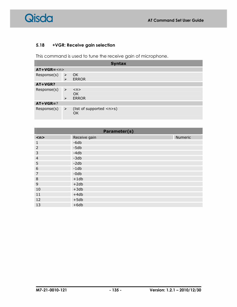
M7-21-0010-121 - 135 - Version: 1.2.1 – 2010/12/30
AT Command Set User Guide
5.18 +VGR: Receive gain selection
This command is used to tune the receive gain of microphone.
Syntax
AT+VGR=<n>
Response(s) � OK � ERROR
AT+VGR?
Response(s) � <n> OK � ERROR
AT+VGR=?
Response(s) � (list of supported <n>s) OK
Parameter(s)
<n> Receive gain Numeric
1 -6db
2 -5db
3 -4db
4 -3db
5 -2db
6 -1db
7 -0db
8 +1db
9 +2db
10 +3db
11 +4db
12 +5db
13 +6db

M7-21-0010-121 - 136 - Version: 1.2.1 – 2010/12/30
AT Command Set User Guide
5.19 +VGT: Transmit gain selection
This command is used to tune the receive gain of microphone.
Syntax
AT+VGT=<n>
Response(s) � OK � ERROR
AT+VGT?
Response(s) � <n> OK � ERROR
AT+VGT=?
Response(s) � (list of supported <n>s) OK
Parameter(s)
<n> Receive gain Numeric
1 -12db
2 -11db
3 -10db
4 -9db
5 -8db
6 -7db
7 -6db
8 -5db
9 -4db
10 -3db
11 -2db
12 -1db
13 0db
14 +1db
15 +2db
16 +3db
17 +4db
18 +5db
19 +6db
20 +7db
21 +8db
22 +9db
23 +10db
24 +11db
25 +12db
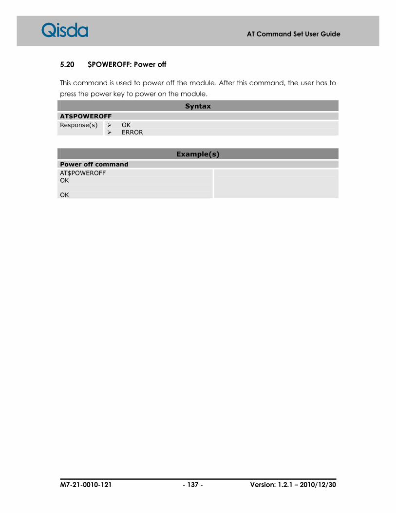
M7-21-0010-121 - 137 - Version: 1.2.1 – 2010/12/30
AT Command Set User Guide
5.20 $POWEROFF: Power off
This command is used to power off the module. After this command, the user has to
press the power key to power on the module.
Syntax
AT$POWEROFF
Response(s) � OK � ERROR
Example(s)
Power off command
AT$POWEROFF OK OK

M7-21-0010-121 - 138 - Version: 1.2.1 – 2010/12/30
AT Command Set User Guide
5.21 $CSQ: Periodic Signal Quality Report
This command is used to start or stop periodic signal quality report.
Syntax
AT$CSQ=<mode>[,<cycle>]
Response(s) � OK $CSQ: <rssi>,<ber> � ERROR
AT$CSQ=?
Response(s) � $CSQ: (list of supported <mode>), (list of supported <cycle>) OK
AT$CSQ?
Response(s) � $CSQ: <mode>[,<cycle>] OK
Parameter(s)
<mode> Numeric
0 STOP
1 START
<cycle> Numeric
1-255 1-255 (seconds), default is 5 (seconds)
<rssi> Received signal strength indication Numeric
0 -113dBm or less
1 -111dBm
2…30 -709dBm~-53dBm
31 -51dBm or greater
99 Unknown or not detectable
<ber> Channel bit error rate Numeric
99 Unknown or not detectable
Example(s)
Start periodic signal quality report
AT$CSQ=1,10 OK $CSQ: 29, 99 /* After 10 seconds */ $CSQ: 29, 99 /* After 10 seconds */
Start periodic signal quality report for every 10 seconds
Stop periodic signal quality report
AT$CSQ=0 OK
Stop periodic signal quality report

M7-21-0010-121 - 139 - Version: 1.2.1 – 2010/12/30
AT Command Set User Guide
5.22 $SP: Control audio path
This command is used to control audio path. There are several combinations of the
audio input and output device.
Syntax
AT$SP=<path>
Response(s) � OK � +CME ERROR: <err>
AT$SP?
Response(s) � $SP: <path> OK
AT$SP=?
� (list of supported <path>s) OK
Parameter(s)
<path> Supported audio path Numeric
0 Handheld path.
1 Handfree path.
2 Digital path.
Example(s)
Set audio path
AT$SP=0 OK AT$SP=1 OK
1. Set to handheld audio path. 2. Set to handfree audio path.
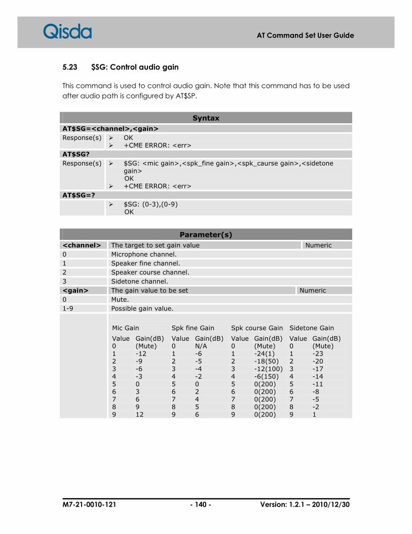
M7-21-0010-121 - 140 - Version: 1.2.1 – 2010/12/30
AT Command Set User Guide
5.23 $SG: Control audio gain
This command is used to control audio gain. Note that this command has to be used
after audio path is configured by AT$SP.
Syntax
AT$SG=<channel>,<gain>
Response(s) � OK � +CME ERROR: <err>
AT$SG?
Response(s) � $SG: <mic gain>,<spk_fine gain>,<spk_caurse gain>,<sidetone gain>
OK � +CME ERROR: <err>
AT$SG=?
� $SG: (0-3),(0-9) OK
Parameter(s)
<channel> The target to set gain value Numeric
0 Microphone channel.
1 Speaker fine channel.
2 Speaker course channel.
3 Sidetone channel.
<gain> The gain value to be set Numeric
0 Mute.
1-9 Possible gain value.
Mic Gain Spk fine Gain Spk course Gain Sidetone Gain
Value Gain(dB) Value Gain(dB) Value Gain(dB) Value Gain(dB) 0 (Mute) 0 N/A 0 (Mute) 0 (Mute) 1 -12 1 -6 1 -24(1) 1 -23 2 -9 2 -5 2 -18(50) 2 -20 3 -6 3 -4 3 -12(100) 3 -17 4 -3 4 -2 4 -6(150) 4 -14 5 0 5 0 5 0(200) 5 -11 6 3 6 2 6 0(200) 6 -8 7 6 7 4 7 0(200) 7 -5 8 9 8 5 8 0(200) 8 -2 9 12 9 6 9 0(200) 9 1

M7-21-0010-121 - 141 - Version: 1.2.1 – 2010/12/30
AT Command Set User Guide
Example(s)
Set gain value
AT$SG=0,5 OK
Set microphone gain value to 5.

M7-21-0010-121 - 142 - Version: 1.2.1 – 2010/12/30
AT Command Set User Guide
5.24 $SAMP: Control audio amplification
This command is used to control audio amplification. Note that this command has to
be used after audio path is configured by AT$SP. The write command is available only
in audio modes 1 to 5.
Syntax
AT$SAMP=<channel>,<amp>
Response(s) � OK � +CME ERROR: <err>
AT$SAMP?
Response(s) � $SAMP: <handheld earpiece amplification>,<handfree speaker amplification>
OK
AT$SAMP=?
� $SAMP: (0-1),(1-4) OK
Parameter(s)
<channel> The target to set amplification value Numeric
0 Handheld earpiece.
1 Handfree speaker.
<amp> The amplification value to be set Numeric
1-4
Handheld earpiece amplification Handfree speaker amplification
Value AMP(dB) Value AMP(dB)
0 N/A 0 N/A
1 -11 1 -22.5
2 1 2 -3.5
3 1 3 2.5
4 1 4 8.5
Example(s)
Set amplification
AT$SAMP=0,4 OK
Set handheld earpiece amplification to 4

M7-21-0010-121 - 143 - Version: 1.2.1 – 2010/12/30
AT Command Set User Guide
5.25 $TRING: Set duration to clip data on incoming call
This command is used to set duration to clip data on incoming call.
Syntax
AT$TRING=<duration>
Response(s) � OK � ERROR
AT$TRING=?
Response(s) � $TRING: (list of supported < duration>s)
OK
AT$TRING?
Response(s) � $TRING: < duration>
OK
Parameter(s)
< duration> Numeric
500-5000 mS
Example(s)
Set Ring duration
AT$TRING=1000 OK
Duration is 1000ms.
M7-21-0010-121 - 144 - Version: 1.2.1 – 2010/12/30
AT Command Set User Guide
5.26 +GDT: Play a call tone
When <TYPE> =1 ~ 18, the MS will enable the <TYPE> of call tone. When <TYPE>
=0, the MS will stop the call tone.
Syntax
AT+GDT=<TYPE>
Response(s) � OK � ERROR
AT+GDT=?
Response(s) � +GDT: (list of supported < type>s) OK
Parameter(s)
< type> Call tone type Numeric
1 Dial Call Tone
2 Authentication Call Tone
3 Ringing Call Tone
4 Busy Call Tone
5 Congested Call Tone
6 Call Drop Call Tone
7 Dial Call Tone
8 Radio Ack Call Tone
9 Waiting Call Tone
10 Timealert Call Tone
11 Auto Redial Call Tone
12 Test Tone Call Tone
13 Warning Beep Call Tone
14 Rising Call Tone
15 Falling Call Tone
16 Forbid Keypad Call Tone
17 Power On Call Tone
18 Error Prompt Call Tone
Example(s)
Play Call tone
AT+GDT=3 OK

M7-21-0010-121 - 145 - Version: 1.2.1 – 2010/12/30
AT Command Set User Guide
5.27 $NOSLEEP: Disable Deep Sleep Mode
This command is used to disable/enable MS of entering deep sleep mode.
Syntax
AT$NOSLEEP=<mode>
Response(s) � OK � ERROR
Parameter(s)
<mode> Call tone type Numeric
0 Enable Deep Sleep Mode
1 Disable Deep Sleep Mode. MS does not enter deep sleep mode.
Example(s)
Disable Deep Sleep Mode
AT$NOSLEEP=1 OK

M7-21-0010-121 - 146 - Version: 1.2.1 – 2010/12/30
AT Command Set User Guide
5.28 $CSSL: Play Tone on Speaker
This command allows a tone to be played on current speaker. Frequency,
gain, and duration can be set.
Syntax
AT$CSSL=<isEnable>[,<gain>,<freq>,<duration>]
Response(s) � OK � ERROR
Parameter(s)
<isEnable> Numeric
0 Stop Playing
1 Play a tone
<gain> Numeric
0~49 This parameter sets the tone gain. The value means that –(0~49)db. The default value is 1.
<freq> Numeric
1~2000 This parameter sets the tone frequency (Hz) (mandatory if <isEnalbe>=1). The range is between 1Hz to 2000Hz.
<duration> Numeric
100~5000 This parameter sets the tone duration (unit of 100ms). When this parameter is 0 (default value), the duration is infinite, and the tone can be stopped by AT$CSSL=0.
Example(s)
Play tone
AT$CSSL=1,15,300,200 OK

M7-21-0010-121 - 147 - Version: 1.2.1 – 2010/12/30
AT Command Set User Guide
5.29 $GLED: Green LED Setting
This command is used to set the duration of green led.
Syntax
AT$GLED=<mode>,<light_duration>,<dark_duration>
Response(s) � OK � ERROR
Parameter(s)
<mode> Numeric
0 Turn off.
1 Turn on.
<light_duration> Numeric
1~65535 Duration of green led to be light.(ms)
<dark_duration> Numeric
1~65535 Duration of green led to be dark.(ms)
Example(s)
Set Green LED Duration
AT$GLED=1,100,200 $GLED:1 OK
M7-21-0010-121 - 148 - Version: 1.2.1 – 2010/12/30
AT Command Set User Guide
5.30 $DTMF: string DTMF and tone generation
This command allows the transmission of DTMF tones and arbitrary tones. These tones
may be used (for example) when announcing the start of a recording period. The
command is write-only. In this profile of commands, this command does not operate
in data or fax modes of operation (+FCLASS=0,1,2-7).
Note: D is used only for dialing.
Syntax
AT$DTMF=<tone>
Response(s) � OK � ERROR
AT$DTMF=?
Response(s) � (list of supported <tone>s) OK
Parameter(s)
<tone> A string of ASCII characters in the set 0-9, #,*,A-D. String
0-9, #,*,A-D
Example(s)
Test command
AT$DTMF=? $DTMF: ”list of digits” OK
Send DTMF string
AT$DTMF=”1234” OK AT$DTMF=”9” OK
Send DTMF of digits 1, 2, 3, 4 Send single DTMF of digit 9

M7-21-0010-121 - 149 - Version: 1.2.1 – 2010/12/30
AT Command Set User Guide
6 Phonebook Commands
6.1 +CPBS: Select phonebook memory storage
Set command selects phonebook memory storage <storage> which is used by other
phonebook commands. If setting is failed in an MS error, +CME ERROR: <err> is
returned.
Read command returns current selected memory together with entry numbers used
and the entire entry numbers in the selected storage.
Test command returns supported storages as compound value.
Syntax
AT+CPBS=<storage>
Response(s) � OK � +CME ERROR:<err>
AT+CPBS?
Response(s) � +CPBS: <storage>[,<used>,<total>] OK
AT+CPBS=?
Response(s) � +CPBS: (list of supported <storage>s) OK
Parameter(s)
<storage> Phonebook memory storage String
“EN” SIM/USIM (or ME) emergency number(+CPBW is not be applicable for this storage)
“BD” Barred dialing number
“FD” SIM fix dialing-phonebook
“DC” MO dialled calls list (+CPBW may not be applicable for this storage)
“LD” SIM/UICC last dialing phonebook
“RC” Last received numbers list
“LR” Last received numbers
“SM” SIM phonebook
“MT” Combined ME and SIM phonebook
“AD” Abbreviated dialing numbers
“SD” Service dialing number
“MC” Last missed number list
“LM” Last missed number
“ON” Own numbers (MSISDN) list
“UD” User person number

M7-21-0010-121 - 150 - Version: 1.2.1 – 2010/12/30
AT Command Set User Guide
<used> Number of used locations in selected storage Numeric
<total> Total entry number in selected memory storage Numeric
Example(s)
Select phonebook memory storage
AT+CPBS=”DC” OK AT+CPBS? +CPBS: "SM",17,100 OK
1. Set phonebook storage 2. Query current value

M7-21-0010-121 - 151 - Version: 1.2.1 – 2010/12/30
AT Command Set User Guide
6.2 +CPBR: Read phonebook entries
Execution command returns phonebook entries in location number ranges between
<index1> and <index2> from the current phonebook memory storage selected by
+CPBS. If <index2> is invalid, only location <index1> is returned. Fields of each entry
returned are location number <indexn>, phone number <number> stored in this
location, (format <type> for phone number), and text <text> associated with the
number, respectively.
If no entries are found at the selected index, the "OK" will be responded.
If it is possible to show Chinese name in phone book, it’s better that “UCS2” is set by
character set (+CSCS) first.
Syntax
AT+CPBR=<index1>[,<index2>]
Response(s) � [+CPBR: <index1>,<number>,<type>,<text>] [+CPBR: <index2>,<number>,<type>,<text>] OK
� +CME ERROR:<err>
AT+CPBR=?
Response(s) � +CPBR: (1-<maxindex>), [<nlength>], [<tlength>] OK
Parameter(s)
<index1> The first reading location number in phonebook memory.
Numeric
<index2> The last reading location number in phonebook memory.
Numeric
<maxindex> Maximum location number for the currently selected storage.
Numeric
<type> Indicating type of address octet in integer format. Numeric
129 ISDN/telephony numbering plan, national/international
145 ISDN/telephony numbering plan, international number
161 ISDN/telephony numbering plan, national number
128-255 Other values refer to GSM 04.08 section 10.5.4.7
<nlength> Indicating the maximum length of field <number> Numeric
<tlength> Indicating the maximum length of field <text> Numeric
<number> Indicating the phone number of format <type> String
<text> Character set specified by command select TE character Set +CSCS
String

M7-21-0010-121 - 152 - Version: 1.2.1 – 2010/12/30
AT Command Set User Guide
Example(s)
Read phonebook entries
AT+CPBS=”SM” OK AT+CPBR=1,5 +CPBR:1,”27998800”,129,”David” +CPBR:3,”27998800”,129,”JENNY” +CPBR:5,”27998800”,129,”Davis” OK
1. ADN phonebook selected 2. Display location number 1,3,5 with location number

M7-21-0010-121 - 153 - Version: 1.2.1 – 2010/12/30
AT Command Set User Guide
6.3 +CPBF: Find phonebook entries
Execution command returns the phonebook entries (from the current phonebook
memory storage selected by +CPBS which alphanumeric fields start from string
<findtext> that is provided. Fields of each entry returned are location number
<indexn>, phone number <number> stored in this location, (format <type> for phone
number), and text <text> associated with the number, respectively. If listing is failed in
an ME error, +CME ERROR: <err> is returned.
Test command returns the maximum lengths of <number> and <text> fields. However,
the lengths may not be available if storage is assigned to SIM.
It is possible to use this command with UCS2 strings. If wrong UCS2 format is provided,
the string is considered as an ASCII string.
Syntax
AT+CPBF=<findtext>
Response(s) � +CPBF:<index1>,<number>,<type>,<text> OK
� +CME ERROR <err>
AT+CPBF=?
Response(s) � +CPBF: [<nlength>],[<tlength>] OK
Parameter(s)
<findtext> Character set specified by command select TE character Set +CSCS. If <findtext> is NULL, +CPBF will list all phonebook entries sorted in alphabetical order.
String
<index1> Value in the range of location numbers of phonebook memory.
Numeric
<number> Indicating the phone number of format <type> String
<type> Indicating type of address octet in integer format. Numeric
128 Unknown type(Unknown number format)
129 ISDN/telephony numbering plan, national/international
145 ISDN/telephony numbering plan, international number
161 ISDN/telephony numbering plan, national number
177 Network specific number(ISDN format)
<text> Character set specified by command select TE character Set +CSCS
String
<nlength> Indicating the maximum length of field <number> Numeric
<tlength> Indicating the maximum length of field <text> Numeric

M7-21-0010-121 - 154 - Version: 1.2.1 – 2010/12/30
AT Command Set User Guide
Example(s)
Find phonebook entries
AT+CPBS=”SM” OK AT+CPBF=”DA” +CPBF: 1,”27998800”,129,”DAVID” +CPBF: 5,”123456”,129,”dad” +CPBF: 8,”222222”,129,”Davis” +CPBF: 10,”99999”,129,”dAllen” OK
1. Select phonebook storage. 2. Find entries start with “DA”.
List all phonebook entries (in alphabetical order)
AT+CPBF=”” +CPBF: 3,”112233”,129,”Allan” +CPBF: 9,”09111111”,129,”Ben” +CPBF: 1,”27998800”,129,”DAVID” +CPBF: 5,”123456”,129,”dad” +CPBF: 8,”222222”,129,”Davis” +CPBF: 10,”99999”,129,”dAllen” +CPBF: 4,”987654”,129,”Eddy” +CPBF: 2,”09222222”,129,”Ella” OK
1. List all entries.
M7-21-0010-121 - 155 - Version: 1.2.1 – 2010/12/30
AT Command Set User Guide
6.4 +CPBW: Write phonebook entry
Set command writes phonebook entry in location number <index> of phonebook
memory <storage> excluding “DC”, “LD”, “MC” and “RC”. Fields of each entry users
need to provide are phone number <number>, (the format <type> for phone
number),and text <text> associated with the number, respectively. If <number> is
provided without <index>, entry is written to the first free location in the phonebook
(the implementation of this feature is manufacturer specific.) If all fields except
<index> are omitted, phonebook storage entry will be deleted. If writing is failed in an
ME error, ERROR is returned.
Syntax
AT+CPBW=[<index>][,<number>[,<type>[,<text>]]]
Response(s) � OK � +CME ERROR <err>
AT+CPBW=?
Response(s) � +CPBW: (list of <index>),[<nlength>],(list of <type>),[<tlength>] OK
Parameter(s)
<index> Value in the range of location numbers of phonebook memory.
Numeric
<number> Indicating the phone number of format <type> String
<type> Indicating type of address octet in integer format. Numeric
128 Unknown type(Unknown number format)
129 ISDN/telephony numbering plan, national/international
145 ISDN/telephony numbering plan, international number
161 ISDN/telephony numbering plan, national number
177 Network specific number(ISDN format)
<text> Character set specified by command select TE character Set +CSCS
String
<nlength> Indicating the maximum length of field <number> Numeric
<tlength> Indicating the maximum length of field <text> Numeric
Example(s)
Write phonebook entry
AT+CPBW=1,”27998800”, 129,”DAVID” OK AT+CPBW=,”27998800”, 129,”DAVID” OK AT+CPBW=1 OK
1. Write at location 1. 2. Write at first location available. 3. Location 1 erased.
M7-21-0010-121 - 156 - Version: 1.2.1 – 2010/12/30
AT Command Set User Guide
6.5 $SMRC: Sim Index Manually Update
For faster searching address book, module backups phone book on SIM into FFS, and
create an index for SIM. If another SIM card is inserted, module will detect the
inconsistence of IMSI and then re-create the index.
There is a scenario makes index asynchronous with SIM. If user remove a SIM card,
edit its address book on another ME, and insert it back to module, module will not
update the index because the same IMSI is detected.
Under this scenario, SIM index need to be updated manually, and AT$SMRC=1 is
suggested. This command sets a flag in FFS, and effect permanently.
Syntax
AT$SMRC=[<enable>][,<number>[,<type>[,<text>]]]
Response(s) � OK � +CME ERROR <err>
AT$SMRC?
Response(s) � $SMRC: [<enable>] OK
Parameter(s)
<enable> Indicating type of address octet in integer format. Numeric
1 Re-create Phone book index in FFS each time module initialize SIM.
0 When module initializes SIM, re-create Phone book index in FFS if IMSI differs. (another SIM card inserted). (default)
Example(s)
Write phonebook entry
AT$SMRC=1 OK AT$SMRC=0 OK
1. Function enabled. Re-create index each time module initializes SIM. 2. Function disabled. Re-create index only when module initializes another SIM.
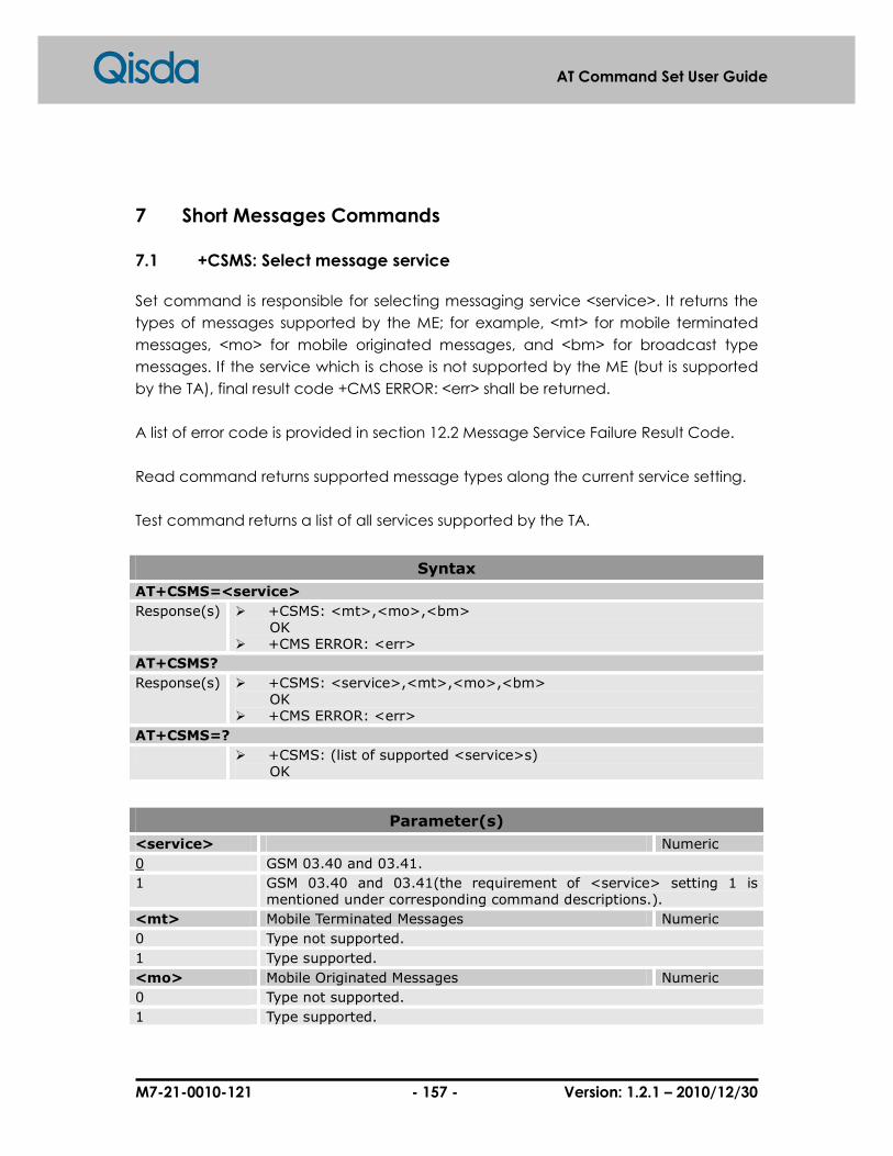
M7-21-0010-121 - 157 - Version: 1.2.1 – 2010/12/30
AT Command Set User Guide
7 Short Messages Commands
7.1 +CSMS: Select message service
Set command is responsible for selecting messaging service <service>. It returns the
types of messages supported by the ME; for example, <mt> for mobile terminated
messages, <mo> for mobile originated messages, and <bm> for broadcast type
messages. If the service which is chose is not supported by the ME (but is supported
by the TA), final result code +CMS ERROR: <err> shall be returned.
A list of error code is provided in section 12.2 Message Service Failure Result Code.
Read command returns supported message types along the current service setting.
Test command returns a list of all services supported by the TA.
Syntax
AT+CSMS=<service>
Response(s) � +CSMS: <mt>,<mo>,<bm> OK � +CMS ERROR: <err>
AT+CSMS?
Response(s) � +CSMS: <service>,<mt>,<mo>,<bm> OK � +CMS ERROR: <err>
AT+CSMS=?
� +CSMS: (list of supported <service>s) OK
Parameter(s)
<service> Numeric
0 GSM 03.40 and 03.41.
1 GSM 03.40 and 03.41(the requirement of <service> setting 1 is mentioned under corresponding command descriptions.).
<mt> Mobile Terminated Messages Numeric
0 Type not supported.
1 Type supported.
<mo> Mobile Originated Messages Numeric
0 Type not supported.
1 Type supported.
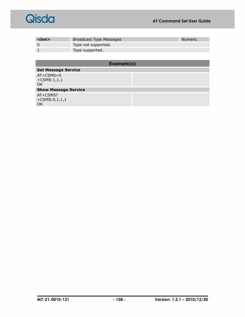
M7-21-0010-121 - 158 - Version: 1.2.1 – 2010/12/30
AT Command Set User Guide
<bm> Broadcast Type Messages Numeric
0 Type not supported.
1 Type supported.
Example(s)
Set Message Service
AT+CSMS=0 +CSMS:1,1,1 OK
Show Message Service
AT+CSMS? +CSMS:0,1,1,1 OK

M7-21-0010-121 - 159 - Version: 1.2.1 – 2010/12/30
AT Command Set User Guide
7.2 +CPMS: Preferred message storage
Set command selects memory storages <mem1>, <mem2> and <mem3> to be used
for reading, writing, etc. If the storage which is chose is not appropriate for the ME
(but is supported by the TA), final result code +CMS ERROR: <err> shall be returned.
A list of error code is provided in section 12.2 Message Service Failure Result Code.
Test command returns lists of memory storages supported by the TA.
Syntax
AT+CPMS=<mem1>[,<mem2>][,<mem3>]
Response(s) � +CPMS: <used1>, <total1>, <used2>, <total2>, <used3>, <total3> OK � +CMS ERROR: <err>
AT+CPMS?
Response(s) � +CPMS: <used1>, <total1>, <used2>, <total2>, <used3>, <total3> OK � +CMS ERROR: <err>
AT+CPMS=?
� +CPMS: (list of supported <mem1>s),(list of supported <mem2>s),(list of supported <mem3>s)
OK
Parameter(s)
<mem1> Memory used to list, read and delete messages. String
“SM” SMS message storage in SIM.
“ME” ME message storage.
Example(s)
Set All ME & Show Message list
AT+CPMS= “ME”,”ME”,”ME” +CPMS: 0,0,0,0,0,0 OK AT+CPMS? +CPMS: “ME”,0,0,”ME”,0,0,”ME”,0,0 OK
Set ME & check message number and total space
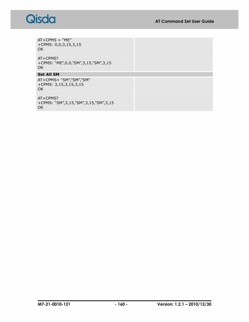
M7-21-0010-121 - 160 - Version: 1.2.1 – 2010/12/30
AT Command Set User Guide
AT+CPMS = “ME” +CPMS: 0,0,3,15,3,15 OK AT+CPMS? +CPMS: “ME”,0,0,”SM”,3,15,”SM”,3,15 OK
Set All SM
AT+CPMS= “SM”,”SM”,”SM” +CPMS: 3,15,3,15,3,15 OK AT+CPMS? +CPMS: “SM”,3,15,”SM”,3,15,”SM”,3,15 OK
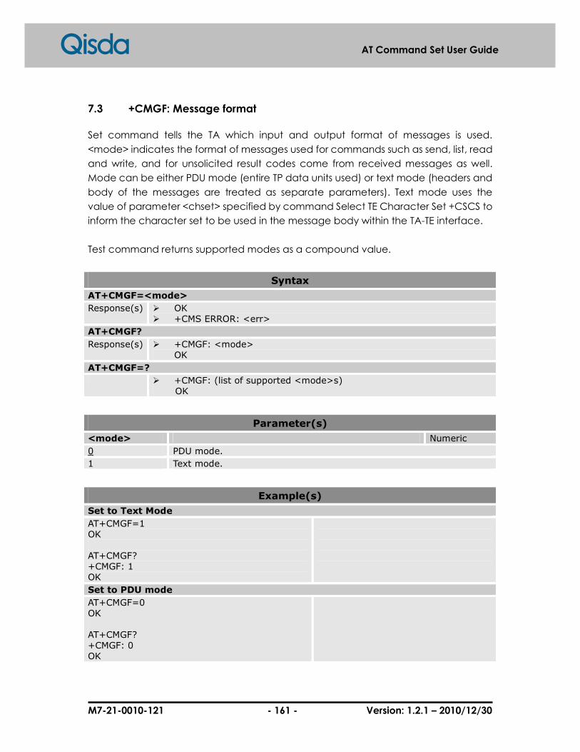
M7-21-0010-121 - 161 - Version: 1.2.1 – 2010/12/30
AT Command Set User Guide
7.3 +CMGF: Message format
Set command tells the TA which input and output format of messages is used.
<mode> indicates the format of messages used for commands such as send, list, read
and write, and for unsolicited result codes come from received messages as well.
Mode can be either PDU mode (entire TP data units used) or text mode (headers and
body of the messages are treated as separate parameters). Text mode uses the
value of parameter <chset> specified by command Select TE Character Set +CSCS to
inform the character set to be used in the message body within the TA-TE interface.
Test command returns supported modes as a compound value.
Syntax
AT+CMGF=<mode>
Response(s) � OK � +CMS ERROR: <err>
AT+CMGF?
Response(s) � +CMGF: <mode> OK
AT+CMGF=?
� +CMGF: (list of supported <mode>s) OK
Parameter(s)
<mode> Numeric
0 PDU mode.
1 Text mode.
Example(s)
Set to Text Mode
AT+CMGF=1 OK AT+CMGF? +CMGF: 1 OK
Set to PDU mode
AT+CMGF=0 OK AT+CMGF? +CMGF: 0 OK

M7-21-0010-121 - 162 - Version: 1.2.1 – 2010/12/30
AT Command Set User Guide
7.4 +CSCA: Service centre address
Set command updates SMS’s address through the service centre where handles
SMS’s transmission. In text mode, setting is used by send and write commands. So
does PDU mode base on the circumstance that the length of the SMSC address
coded into <pdu> parameter equals zero.
Syntax
AT+CSCA = <sca>[,<tosca>]
Response(s) � OK � +CMS ERROR: <err>
AT+CSCA?
Response(s) � +CSCA: <sca>,<tosca> OK � +CMS ERROR: <err>
Parameter(s)
<sca> Service center address String
<tosca> Type of service center address Numeric
145 When <sca> first character of <da> is +(IRA 43).
129 When <sca> first character of <da> is not +(IRA 43).
Example(s)
Set SC address
AT+CSCA=”+886935074443”,145 OK
Read SC address
AT+CSCA? +CSCA: “+886935074443”,145 OK

M7-21-0010-121 - 163 - Version: 1.2.1 – 2010/12/30
AT Command Set User Guide
7.5 +CSMP: Text mode parameters
Set command is used to select values for additional parameters needed when SM is
sent to the network or placed in a storage when text format message mode is
selected. It is possible to set the valid period starts from the time SM is received by
SMSC (<vp> is in range 0... 255) or to define the absolute and valid period for
termination (<vp> is a string). The format of <vp> is provided by <fo>.
NOTE: When it stores a SMS-DELIVER from the TE to the preferred memory storage in
text mode (refer command Write Message to Memory +CMGW), <vp> field can be
used for <scts>.
Syntax
AT+CSMP=<fo>[,<vp>[,<pid>[,<dcs>]]]
Response(s) � OK � +CMS ERROR: <err>
AT+CSMP?
Response(s) � +CSMP: <fo>,<vp>,<pid>,<dcs> OK
� +CMS ERROR: <err>
Parameter(s)
<fo> Bit 4, Bit 3 TP-VPF 00 TP-VP field not present 10 TP-VP field present – relative format 01 TP-VP field present – enhanced format (not supported) 11 TP-VP field present – absolute format Bit 2 TP-RD (Reserved) Bit 1, Bit 0 TP-MTI 01 SMS-SUBMIT (in the direction MS to SC)
Numeric
17
<vp> Validity period Numeric
0-143 (vp + 1) * 5 minutes
144-167 12 hours + ((vp – 143) * 30 minutes)
168-196 (vp – 166) * 1 day
197-255 (vp – 192) * 1 week
<pid> Protocol identifier. Please see GSM 03.40 TP-Protocol-Identifier (TP-PID) description.
Numeric
0 Default value.
1-255 Protocol identifier.
<dcs> Data coding scheme. Please check GSM 03.38 SMS Data Coding Scheme for detail.
Numeric

M7-21-0010-121 - 164 - Version: 1.2.1 – 2010/12/30
AT Command Set User Guide
0 Default alphabet.
4 8 bit data.
8 UCS2 (16bit).
Example(s)
Set parameter for saving/sending short message
AT+CSMP=17,168,0,0 OK
Set <vp>=2 days, <pid>=0 and <dcs>=0

M7-21-0010-121 - 165 - Version: 1.2.1 – 2010/12/30
AT Command Set User Guide
7.6 +CSDH: Show text mode parameters
+CSDH command controls whether or not the detailed header information is shown
from the result codes in text mode.
Syntax
AT+CSDH =<show>
Response(s) � OK � +CMS ERROR: <err>
AT+CSDH?
Response(s) � +CSDH: <show> OK
AT+CSDH=?
� +CSDH: (list of supported <show>s) OK
Parameter(s)
<show> Control displaying header values defined in commands +CSCA and +CSMP (<sca>, <tosca>, <fo>, <vp>, <pid> and <dcs>) nor <length>, <toda> or <tooa> in +CMT, +CMGL, +CMGR result codes for SMS-DELIVERs and SMS-SUBMITs in text mode; for SMS-COMMANDs in +CMGR result code, do not show <pid>, <mn>, <da>, <toda>, <length> or <cdata>.
Numeric
0 Don’t show those information.
1 Show those information.

M7-21-0010-121 - 166 - Version: 1.2.1 – 2010/12/30
AT Command Set User Guide
7.7 +CSCB: Select cell broadcast message types
Set command selects which types of CBMs are received by the ME.
Test command returns supported modes as a compound value.
If <mids> or <dcss> is set to an empty string, there is no action on <mids> or <dcss>.
Syntax
AT+CSCB=<mode>[,<mids>[,<dcss>]]
Response(s) � OK � +CMS ERROR: <err>
AT+CSCB?
Response(s) � +CSCB: <mode>,<mids>,<dcss> OK +CMS ERROR: <err>
AT+CSCB=?
� +CSCB: (list of supported <mode>s) OK
Parameter(s)
<mode> Message mode Numeric
0 Message types specified in <mids> and <dcss> are accepted.
1 Message types specified in <mids> and <dcss> are not accepted.
<mids> Cell Broadcast Message(CBM) ID combinations or range. Default is empty string.
String
<dcss> CBM data coding scheme. Default is empty string. String
Example(s)
Read message types
AT+CSCB? +CSCB: 0,”1,4,10”,”2,3” OK
Set message types in supported range
AT+CSCB=0,”1,4,5”,”3,4” OK AT+CSCB? +CSCB=0, “1,4,5”,”3,4” OK
Set message types out of supported range
AT+CSCB=0,”65536”,”7,8” +CMS ERROR: 302 AT+CSCB?

M7-21-0010-121 - 167 - Version: 1.2.1 – 2010/12/30
AT Command Set User Guide
+CSCB=0,”1,4,5”,”3,4” OK
Set <mids> or <dcss> in the command to be unaccepted
AT+CSCB=1,”2-5”,”8” OK AT+CSCB? +CSCB=1,”2-5”,”8” OK

M7-21-0010-121 - 168 - Version: 1.2.1 – 2010/12/30
AT Command Set User Guide
7.8 +CSAS: Save settings
Execution command saves active message service settings into a non-volatile
memory. A TA can contain several profiles of settings. Settings specified in commands
such as Service Centre Address +CSCA, Set Message Parameters +CSMP and Select
Cell Broadcast Message Types +CSCB (if implemented) are saved. Certain settings
may not be supported by the storage (e.g. (U)SIM SMS parameters) and therefore
can not be saved.
Syntax
AT+CSAS=<profile>
Response(s) � OK � +CMS ERROR: <err>
AT+CSAS=?
Response(s) � +CSAS: (list of supported <profile>s) OK
Parameter(s)
<profile> Profile number where settings to be stored Numeric
0 Profile 0.
1 Profile 1.

M7-21-0010-121 - 169 - Version: 1.2.1 – 2010/12/30
AT Command Set User Guide
7.9 +CRES: Restore settings
Execution command restores message service settings from non-volatile memory to
active memory. A TA can contain several profiles of settings. Settings specified in
commands such as Service Centre Address +CSCA, Set Message Parameters +CSMP
and Select Cell Broadcast Message Types +CSCB (if implemented) are restored.
Certain settings may not be supported by the storage (e.g. (U)SIM SMS parameters)
and therefore can not be restored.
Syntax
AT+CRES=<profile>
Response(s) � OK � +CMS ERROR: <err>
+CRES=?
Response(s) � +CRES: (list of supported <profile>s) OK
Parameter(s)
<profile> Profile number where settings to be stored Numeric
0 Profile 0.
1 Profile 1.

M7-21-0010-121 - 170 - Version: 1.2.1 – 2010/12/30
AT Command Set User Guide
7.10 +CNMI: New message indications to TE
The indication will be sent from the network to TE when TE is active; for example, DTR
signal is ON. <mode> controls the processing of unsolicited result codes specified
within this command, <mt> sets the result code indication routing for SMS-DELIVERs,
<bm> for CBMs and <ds> for SMS-STATUS-REPORTs. <bfr> defines the handling method
for buffered result codes when <mode> 1, 2 or 3 is enabled. If ME does not support
requested item (although TA does), final result code +CMS ERROR: <err> is returned.
Test command returns the settings supported by the TA as compound values.
NOTE: Command Select Message Service +CSMS should be used to detect ME
support of mobile terminated SMs and CBMs, and to define whether a message
which is routed directly to TE should be acknowledged or not.
Syntax
AT+CNMI=<mode>[,<mt>[,<bm>[,<ds>[,<bfr>]]]]
Response(s) � OK � +CMS ERROR: <err>
AT+CNMI?
Response(s) � +CNMI: <mode>,<mt>,<bm>,<ds>, <bfr> OK
AT+CNMI=?
� +CNMI: (list of supported <mode>s), (list of supported <mt>s), (list of supported <bm>s),(list of supported <ds>s), (list of supported <bfr>s)
OK
Parameter(s)
<mode> Numeric
0 Buffer unsolicited result codes in the TA. If TA result code buffer is full, indications can be buffered in some other place or the oldest indications may be discarded and replaced with the new receiver indications.
1 Discard indication and reject new received message unsolicited result code when TA-TE link is reserved (e.g. in on-line data mode). Otherwise forward them directly to the TE.
2 Buffer unsolicited result codes in the TA when TA-TE link is reserved (e.g. in on-line data mode) and flush them to the TE after reservation. Otherwise forward them directly to the TE.
<mt> Numeric
0 No SMS-DELIVER (message to ME) indications are routed to the TE. Default.
1 SMS-DELIVER is stored in ME. Indication of the memory location is routed to the TE by using the unsolicited result code:

M7-21-0010-121 - 171 - Version: 1.2.1 – 2010/12/30
AT Command Set User Guide
+CMTI: <mem>, <index>
2 class 0, class 1 and class 3 SMS-DELIVERs are routed directly to the TE using unsolicited result code: +CMT: [<alpha>],<length><CR><LF><pdu> (PDU mode enabled) or +CMT: <oa>, <alpha>],<scts>,<tooa>,<fo>,<pid>,<dcs>, <sca>,<tosca>,<length>]<CR><LF><data> (text mode enabled; about parameters in italics, refer command +CSDH) class 0 message and messages in the message waiting indication group (discard message), may be copied to TE, In this case , ME shall send the acknowledgement to the network. Class2 message and messages in the message waiting indication group (store message) result in indication as defined in <mt>=1.
3 Class 3 SMS-DELIVERs are routed directly to TE using unsolicited result codes defined in <mt>=2. Messages of other data coding schemes result in indication as defined in <mt>=1.
<bm> Numeric
0 No CBM indications are routed to the TE.
2 CBM is routed directly to the TE by using the unsolicited result code: +CBM: <length><CR><LF><pdu> (PDU mode enabled) or +CBM: <sn>,<mid>,<dcs>,<page>,<pages><CR><LF> <data> (text mode enabled) refer to 03.41, Content of message is limited to 82 bytes and total pages are no more than 15.
<ds> Numeric
0 No SMS-STATUS-REPORTs are routed to the TE
1 SMS-STATUS-REPORTs are routed to the TE using unsolicited result code: +CDS: <length><CR><LF><pdu> (PDU mode enabled) or +CDS: <fo>,<mr>,[<ra>],[<tora>],<scts>,<dt>,<st> (text mode enabled)
<bfr> Numeric
0 TA buffer of unsolicited result codes defined within this command is flushed to the TE when <mode> 1…3 is entered (OK response shall be given before flushing the codes).
1 TA buffer of unsolicited result codes defined within this command is cleared when <mode> 1..3 is entered.
Example(s)
AT+CNMI=? +CNMI: (0-2),(0-3),(0,2),(0,1),(0,1) OK AT+CNMI? +CNMI: 0,0,0,0,0 OK AT+CNMI =0,0,0,0,0

M7-21-0010-121 - 172 - Version: 1.2.1 – 2010/12/30
AT Command Set User Guide
OK AT+CNMI? +CNMI: 0,0,0,0,0 OK AT+CNMI =1,3,2,1,1 OK AT+CNMI? +CNMI: 1,3,2,1,1 OK
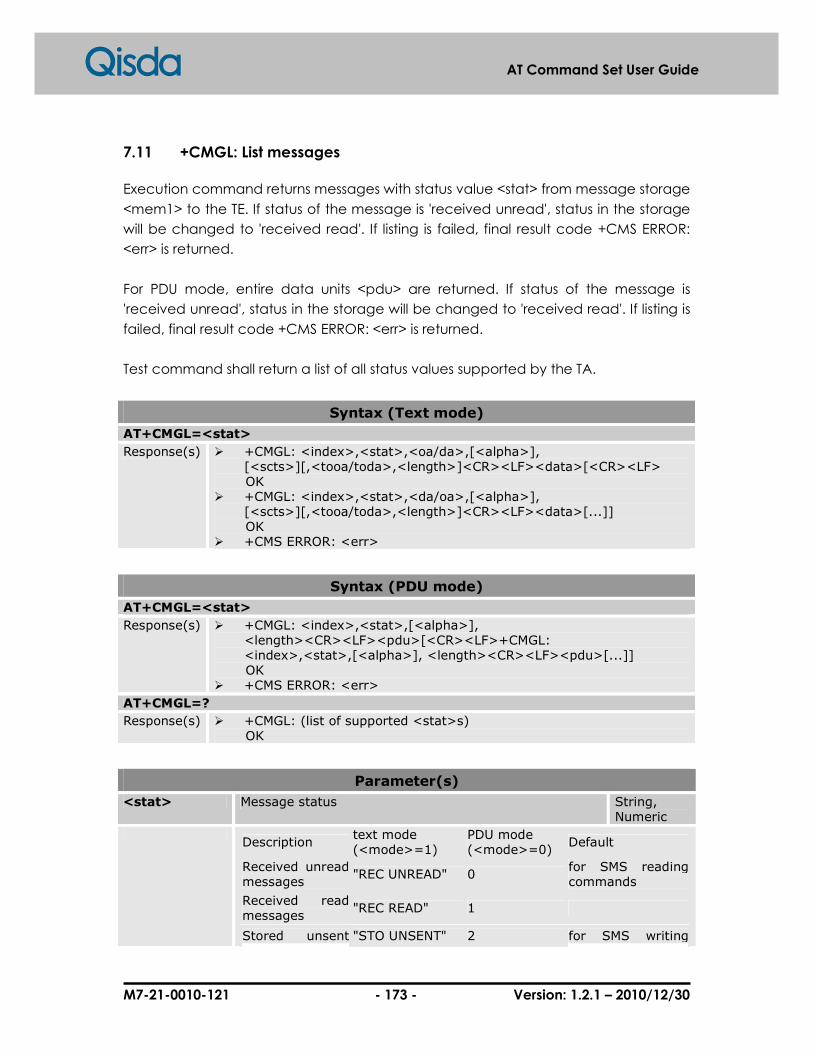
M7-21-0010-121 - 173 - Version: 1.2.1 – 2010/12/30
AT Command Set User Guide
7.11 +CMGL: List messages
Execution command returns messages with status value <stat> from message storage
<mem1> to the TE. If status of the message is 'received unread', status in the storage
will be changed to 'received read'. If listing is failed, final result code +CMS ERROR:
<err> is returned.
For PDU mode, entire data units <pdu> are returned. If status of the message is
'received unread', status in the storage will be changed to 'received read'. If listing is
failed, final result code +CMS ERROR: <err> is returned.
Test command shall return a list of all status values supported by the TA.
Syntax (Text mode)
AT+CMGL=<stat>
Response(s) � +CMGL: <index>,<stat>,<oa/da>,[<alpha>], [<scts>][,<tooa/toda>,<length>]<CR><LF><data>[<CR><LF>
OK � +CMGL: <index>,<stat>,<da/oa>,[<alpha>],
[<scts>][,<tooa/toda>,<length>]<CR><LF><data>[...]] OK � +CMS ERROR: <err>
Syntax (PDU mode)
AT+CMGL=<stat>
Response(s) � +CMGL: <index>,<stat>,[<alpha>], <length><CR><LF><pdu>[<CR><LF>+CMGL: <index>,<stat>,[<alpha>], <length><CR><LF><pdu>[...]]
OK � +CMS ERROR: <err>
AT+CMGL=?
Response(s) � +CMGL: (list of supported <stat>s) OK
Parameter(s)
<stat> Message status String, Numeric
Description
text mode (<mode>=1)
PDU mode (<mode>=0)
Default
Received unread messages
"REC UNREAD" 0 for SMS reading commands
Received read messages
"REC READ" 1
Stored unsent "STO UNSENT" 2 for SMS writing

M7-21-0010-121 - 174 - Version: 1.2.1 – 2010/12/30
AT Command Set User Guide
messages commands
Stored sent messages
"STO SENT" 3
All messages "ALL" 4
<index> Index value of supported memory location numbers Numeric
<oa/da> Originating Address/Destination Address String
<alpha> Alphanumeric representation of <da> or <oa> String
<scts> Service centre time stamp Numeric
<tooa/toda> Type of Originating Address/Type of Destination Address. Numeric
145 When first character of <da> is + (IRA 43).
129 When first character of <da> is not +.
<length> Message length Numeric
<pdu> The message with PDU format Numeric
Example(s)
List All Messages in text mode
AT+CMGF=1 OK AT+CMGL=”ALL” +CMGL: 2,”STO UNSENT”,”0921214863”,,,129,4 TEST OK AT+CMGL=”STO UNSENT” +CMGL: 2,”STO UNSENT”,”0921214863”,,,129,4 TEST OK
1. Set message format to text mode. 2. List all messages
List All Messages in PDU mode
AT+CMGF=0 OK AT+CMGL=2 +CMGL: 1,2,,8 0791889683434822110000800004A800 +CMGL: 2,2,,36 079188968343482251B702812200008F1E040D021800A0E974B8EEF5BADFEF2E71D91D778DDF6D903A4C0601 +CMGL: 3,2,,8 0791889683434822110000800004A800 +CMGL: 4,2,,35 079188968343482251BA02812500008F1D0A0A030606010A030C04020893D567BA421D26ABE98A7B5B1D06 +CMGL: 5,2,,9 0791889683434822110000800004A801E1 +CMGL: 6,2,,9 0791889683434822110000800004A801E4 OK
1. Set message format to PDU mode. 2. List "STO UNSENT" message

M7-21-0010-121 - 175 - Version: 1.2.1 – 2010/12/30
AT Command Set User Guide
7.12 +CMGD: Delete message
Execution command deletes message from preferred message storage <mem1>
location <index>.
Syntax
AT+CMGD=<index>[,<delflag>]
Response(s) � OK � +CMS ERROR: <err>
Parameter(s)
<index> Index value of supported memory location numbers Numeric
<delflag> An integer indicating multiple message deletion request Numeric
1 REC READ MT record, already read 2 STO UNSENT MO record, not sent 3 STO SENT MO record, already sent 4 or 5 ALL All record
Example(s)
Delete Message number 7
AT+CMGD=7 OK
Delete all ”REC READ” Messages
AT+CMGD=0,1 OK
Delete all ”STO_UNSENT” Messages
AT+CMGD=0,2 OK
Delete all ”STO SENT” Messages
AT+CMGD=0,3 OK
Delete ”ALL” Messages
AT+CMGD=0,4 OK
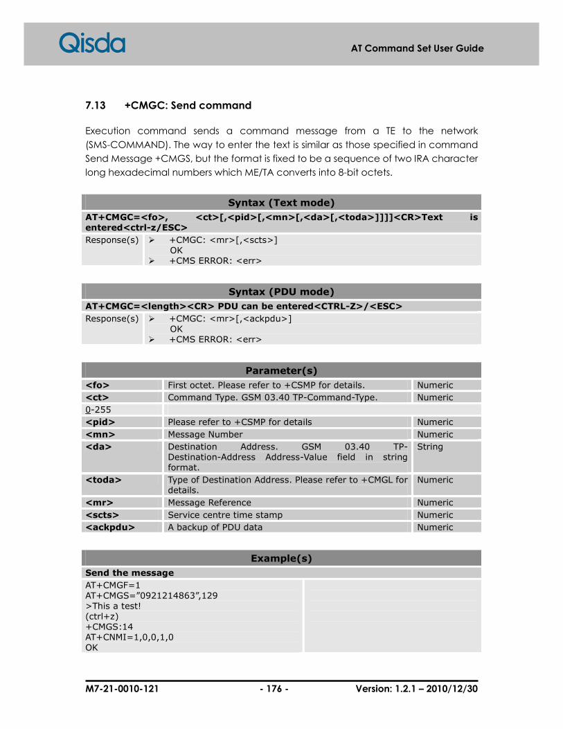
M7-21-0010-121 - 176 - Version: 1.2.1 – 2010/12/30
AT Command Set User Guide
7.13 +CMGC: Send command
Execution command sends a command message from a TE to the network
(SMS-COMMAND). The way to enter the text is similar as those specified in command
Send Message +CMGS, but the format is fixed to be a sequence of two IRA character
long hexadecimal numbers which ME/TA converts into 8-bit octets.
Syntax (Text mode)
AT+CMGC=<fo>, <ct>[,<pid>[,<mn>[,<da>[,<toda>]]]]<CR>Text is entered<ctrl-z/ESC>
Response(s) � +CMGC: <mr>[,<scts>] OK � +CMS ERROR: <err>
Syntax (PDU mode)
AT+CMGC=<length><CR> PDU can be entered<CTRL-Z>/<ESC>
Response(s) � +CMGC: <mr>[,<ackpdu>] OK � +CMS ERROR: <err>
Parameter(s)
<fo> First octet. Please refer to +CSMP for details. Numeric
<ct> Command Type. GSM 03.40 TP-Command-Type. Numeric
0-255
<pid> Please refer to +CSMP for details Numeric
<mn> Message Number Numeric
<da> Destination Address. GSM 03.40 TP- Destination-Address Address-Value field in string format.
String
<toda> Type of Destination Address. Please refer to +CMGL for details.
Numeric
<mr> Message Reference Numeric
<scts> Service centre time stamp Numeric
<ackpdu> A backup of PDU data Numeric
Example(s)
Send the message
AT+CMGF=1 AT+CMGS=”0921214863”,129 >This a test! (ctrl+z) +CMGS:14 AT+CNMI=1,0,0,1,0 OK

M7-21-0010-121 - 177 - Version: 1.2.1 – 2010/12/30
AT Command Set User Guide
AT+CMGC=,,,14,”0921214863”,129 > (ctrl+z) +CMGC: 15 +CDS:SMS-STATUS-REPORT

M7-21-0010-121 - 178 - Version: 1.2.1 – 2010/12/30
AT Command Set User Guide
7.14 +CMGR: Read message
For text mode, execution command returns message with location value <index>
from message storage <mem1> to the TE. If status of the message is 'received unread',
status in the storage will be changed to 'received read'. If reading is failed, final result
code +CMS ERROR:<err> is returned.
For PDU mode, execution command returns message with location value <index>
from preferred message storage <mem1> to the TE. Status of the message and entire
message data unit <pdu> are both returned. If status of the message is 'received
unread', status in the storage will be changed to 'received read'. If reading is failed,
final result code +CMS ERROR: <err> is returned.
Syntax (Test mode)
AT+CMGR=<index>
Response(s) � +CMGR: <stat>,<oa>,[<alpha>],<scts>[,<tooa>, <fo>,<pid>,<dcs>,<sca>,<tosca>,<length>]<CR><LF><data>
OK � +CMGR: <stat>,<da>,[<alpha>][,<toda>,<fo>,
<pid>,<dcs>,[<vp>],<sca>,<tosca>,<length>]<CR><LF><data> OK � +CMS ERROR: <err>
Syntax (PDU mode)
AT+CMGR=<index>
Response(s) � +CMGR:<stat>,[<alpha>],<length><CR><LF><pdu> OK � +CMS ERROR: <err>
Parameter(s)
<index> Index value of supported memory location numbers Numeric
<stat> Message status. Please refer to +CMGL for details. String, Numeric
<oa> Originating address. 03.40 TP-Originating-Address Address-Value field in string format.
String
<alpha> Alphanumeric representation of <da> or <oa> String
<scts> Service centre time stamp Numeric
<tooa> Type of originating address. Please refer to +CMGL for details.
String
<fo> First octet. Please refer to +CSMP for details. Numeric
<pid> Please refer to +CSMP for details Numeric
<dcs> Data coding scheme. Please check GSM 03.38 SMS Data Coding Scheme for detail.
Numeric
<sca> Service center address String
<tosca> Type of service center address Numeric

M7-21-0010-121 - 179 - Version: 1.2.1 – 2010/12/30
AT Command Set User Guide
<length> Message length Numeric
<da> Destination Address. GSM 03.40 TP- Destination-Address Address-Value field in string format.
String
<vp> Validity period. Please refer to +CSMP for details. Numeric
<pdu> The message with PDU format Numeric
Example(s)
Read the message in text mode
AT+CMGR=0;+CMGR=1;+CMGR=2;+CMGR=4 +CMGR: 2,,26 079188968343482211B602812500008F13683A1DAE7BBDEEF7BB4B5C76C75DE3771B +CMGR: 2,,26 079188968343482211B602812500008F13683A1DAE7BBDEEF7BB4B5C76C75DE3771B +CMGR: 2,,36 079188968343482251B702812200008F1E040D021800A0E974B8EEF5BADFEF2E71D91D778DDF6D90 3A4C0601 +CMGR: 2,,35 079188968343482251BA02812500008F1D0A0A030606010A030C04020893D567BA421D26ABE98A7B 5B1D06 OK
1. Read message of index 0, 1, 2, 4
Read the message in PDU mode
AT+CMGF=0 OK AT+CMGR=2 +CMGR: 2,,36 079188968343482251B702812200008F1E040D021800A0E974B8EEF5BADFEF2E71D91D778DDF6D90 3A4C0601 OK AT+CMGR=4 +CMGR: 2,,35 079188968343482251BA02812500008F1D0A0A030606010A030C04020893D567BA421D26ABE98A7B 5B1D06 OK AT+CMGR=3 +CMGR: 2,,8 0791889683434822110000800004A800 OK AT+CMGR=5 +CMGR: 2,,9
1. Set message format to PDU mode. 2. Read message index 2. 3. Read message index 4. 4. Read message index 3. 5. Read message index 5.

M7-21-0010-121 - 180 - Version: 1.2.1 – 2010/12/30
AT Command Set User Guide
0791889683434822110000800004A801E1 OK

M7-21-0010-121 - 181 - Version: 1.2.1 – 2010/12/30
AT Command Set User Guide
7.15 +CNMA: New message acknowledgement to ME/TA
Execution command confirms correct response to a new message (SMS=DELIVER or
SMS-STATUS-REPORT) which is routed directly to the TE (refer command +CNMI tables 2
and 4). This acknowledgement command (causes ME to send RP-ACK to the network)
shall be used when +CSMS parameter <service> equals 1. TA shall not send another
+CMT or +CDS result code to TE before previous one is acknowledged.
If ME does not get acknowledgement within a specific period (network timeout), ME
should send RP-ERROR to the network. ME/TA shall automatically disable the ability of
routing to TE by setting both <mt> and <ds> values of +CNMI to zero.
If command is executed without receiving any acknowledgement, or some other ME
related error occurs, final result code +CMS ERROR: <err> is returned.
A list of error code is provided in section 12.2 Message Service Failure Result Code.
Syntax
AT+CNMA
Response(s) � OK � +CMS ERROR: <err>

M7-21-0010-121 - 182 - Version: 1.2.1 – 2010/12/30
AT Command Set User Guide
7.16 +CMGS: Send short message
Execution command sends message from a TE to the network (SMS-SUBMIT). Message
reference value <mr> is returned to the TE on successful message delivery. <scts> is
optionally returned (when +CSMS <service> value is 1 and network supports). Values
can be used to identify message upon unsolicited delivery status reports result code.
If sending is failed in a network or an ME error, final result code +CMS ERROR: <err> is
returned. This command can be abort.
Syntax (Text mode)
AT+CMGS =<da>[,<toda>]<CR> Text is entered<ctrl-Z/ESC>
Response(s) � +CMGS: <mr>[,<scts>] OK
� +CMS ERROR: <err>
Syntax (PDU mode)
AT+CMGS=<length><CR> PDU is given<ctrl-Z/ESC>
Response(s) � +CMGS: <mr>[,<ackpdu>] OK
� +CMS ERROR: <err>
Parameter(s)
<da> Destination Address. GSM 03.40 TP- Destination-Address Address-Value field in string format.
String
<toda> Type of Destination Address. Please refer to +CMGL for details.
Numeric
<mr> Message Reference Numeric
<ackpdu> A backup of PDU data Numeric
Example(s)
Send message in Text mode
AT+CMGF=1 OK AT+CMGS=”0921214863” > TEST +CMGS: 230 OK
1. Set Text mode 2. Send the message “TEST” to 0921214863

M7-21-0010-121 - 183 - Version: 1.2.1 – 2010/12/30
AT Command Set User Guide
7.17 +CMSS: Send short message from the storage
Execution command sends message with location value <index> from preferred
message storage <mem2> to the network (SMS-SUBMIT). If new recipient address
<da> is provided for SMS-SUBMIT, it shall be used instead of choosing the one stored
with the message. Reference value <mr> is returned to the TE on successful message
delivery. If sending is failed in a network or an ME error, final result code +CMS ERROR:
<err> is returned. This command can be abort.
Syntax
AT+CMSS=<index>[,<da>[,<toda>]]
Response(s) � +CMSS: <mr> OK
� +CMS ERROR: <err>
Parameter(s)
<index> Index value of supported memory location numbers Numeric
<da> Destination Address. GSM 03.40 TP- Destination-Address Address-Value field in string format.
String
<toda> Type of Destination Address. Please refer to +CMGL for details.
Numeric
Example(s)
Send message from storage in Text mode
AT+CMGF=1 OK AT+CMGW=”0921214863” > TEST1 +CMGW: 11 OK AT+CMSS=11 +CMSS: 234 OK
1. Set Text mode. 2. Write the message “TEST” to into memory. 3. Send the message in index 11.

M7-21-0010-121 - 184 - Version: 1.2.1 – 2010/12/30
AT Command Set User Guide
7.18 +CMGW: Send Write Message to Memory
Execution command stores a message (either SMS-DELIVER or SMS-SUBMIT) to memory
storage <mem2>. Memory location <index> of the stored message is returned.
Althoug message status will be set to 'stored unsent' by default, parameter <stat> can
be provided by other status values. The entering of PDU is done similarly as those
specified in command Send Message +CMGS. If writing is failed, final result code
+CMS ERROR: <err> is returned. This command can be abort.
Syntax (Text mode)
AT+CMGW[=<da>[,<toda>[,<stat>]]]<CR> text is entered<ctrl-Z/ESC>
Response(s) � +CMGW: <index> OK
� +CMS ERROR: <err>
Syntax (PDU mode)
AT+CMGW[=<length>[,<stat>]<CR> PDU is given<ctrl-Z/ESC>
Response(s) � +CMGW: <index> OK
� +CMS ERROR: <err>
Parameter(s)
<da> Destination Address. GSM 03.40 TP- Destination-Address Address-Value field in string format.
String
<toda> Type of Destination Address. Please refer to +CMGL for details.
Numeric
<stat> Message status. Please refer to +CMGL for details. String, Numeric
<length> Message Length Numeric
Example(s)
Write a SMS in text mode
AT+CMGF=1 OK AT+CMGW=”0921214863” > TEST1 +CMGW: 11 OK
1. Set text mode. 2. Write the message “TEST1” into memory.

M7-21-0010-121 - 185 - Version: 1.2.1 – 2010/12/30
AT Command Set User Guide
8 Fax Control
8.1 +FDT: Send a page
The FDT command requests the DCE to transmit a Phase C page. It is issued at the
beginning of each page, either in Phase B or in Phase D. When the DCE is ready to
accept Phase C data, it shall issue the negotiation responses and the CONNECT result
code to the DTE. Negotiation responses are controlled by the FNR sub parameters
(8.5.1.11/T.32).
In Phase B (after ATA, ATD or the end of a document), the FDT command releases the
DCE to keep processing with negotiation and releases the DCS message to the
remote station. In Phase D (after sending a page), the FDT command resumes
transmission after the end of a previous page.
The FDT command returns a positive CONNECT result code response if the DCE is
ready for data; otherwise, it will return others (e.g. FHS:<hangup code>). Following the
CONNECT message, the DTE shall deliver image data to the DCE as negotiated. After
image data is delivered, the DTE shall deliver a <DLE><ppm> a pair of characters
(8.3.3.7/T.32) to mark the end of the data and to indicate subsequent actions.
The FDT command results in an ERROR result code response if the DCE is on-hook.
Syntax
AT+FDT
Response(s) � [+FNF:<NSF FIF data>] [+FCI:<remote ID>] [+FIS:<parameters>] [+FCS:<parameters>] CONNECT
� +FHS:<hangup code> OK
� ERROR
Example(s)
AT+FDT +FCS:0,3,0,0,0,0,2,0 CONNECT
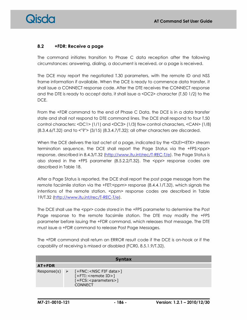
M7-21-0010-121 - 186 - Version: 1.2.1 – 2010/12/30
AT Command Set User Guide
8.2 +FDR: Receive a page
The command initiates transition to Phase C data reception after the following
circumstances: answering, dialing, a document is received, or a page is received.
The DCE may report the negotiated T.30 parameters, with the remote ID and NSS
frame information if available. When the DCE is ready to commence data transfer, it
shall issue a CONNECT response code. After the DTE receives the CONNECT response
and the DTE is ready to accept data, it shall issue a <DC2> character (T.50 1/2) to the
DCE.
From the +FDR command to the end of Phase C Data, the DCE is in a data transfer
state and shall not respond to DTE command lines. The DCE shall respond to four T.50
control characters: <DC1> (1/1) and <DC3> (1/3) flow control characters, <CAN> (1/8)
(8.3.4.6/T.32) and to <"?"> (3/15) (8.3.4.7/T.32); all other characters are discarded.
When the DCE delivers the last octet of a page, indicated by the <DLE><ETX> stream
termination sequence, the DCE shall report the Page Status via the +FPS:<ppr>
response, described in 8.4.3/T.32 (http://www.itu.int/rec/T-REC-T/e). The Page Status is
also stored in the +FPS parameter (8.5.2.2/T.32). The <ppr> response codes are
described in Table 18.
After a Page Status is reported, the DCE shall report the post page message from the
remote facsimile station via the +FET:<ppm> response (8.4.4.1/T.32), which signals the
intentions of the remote station. <ppm> response codes are described in Table
19/T.32 (http://www.itu.int/rec/T-REC-T/e).
The DCE shall use the <ppr> code stored in the +FPS parameter to determine the Post
Page response to the remote facsimile station. The DTE may modify the +FPS
parameter before issuing the +FDR command, which releases that message. The DTE
must issue a +FDR command to release Post Page Messages.
The +FDR command shall return an ERROR result code if the DCE is on-hook or if the
capability of receiving is missed or disabled (FCR0, 8.5.1.9/T.32).
Syntax
AT+FDR
Response(s) � [+FNC:<NSC FIF data>] [+FTI:<remote ID>] [+FCS:<parameters>] CONNECT
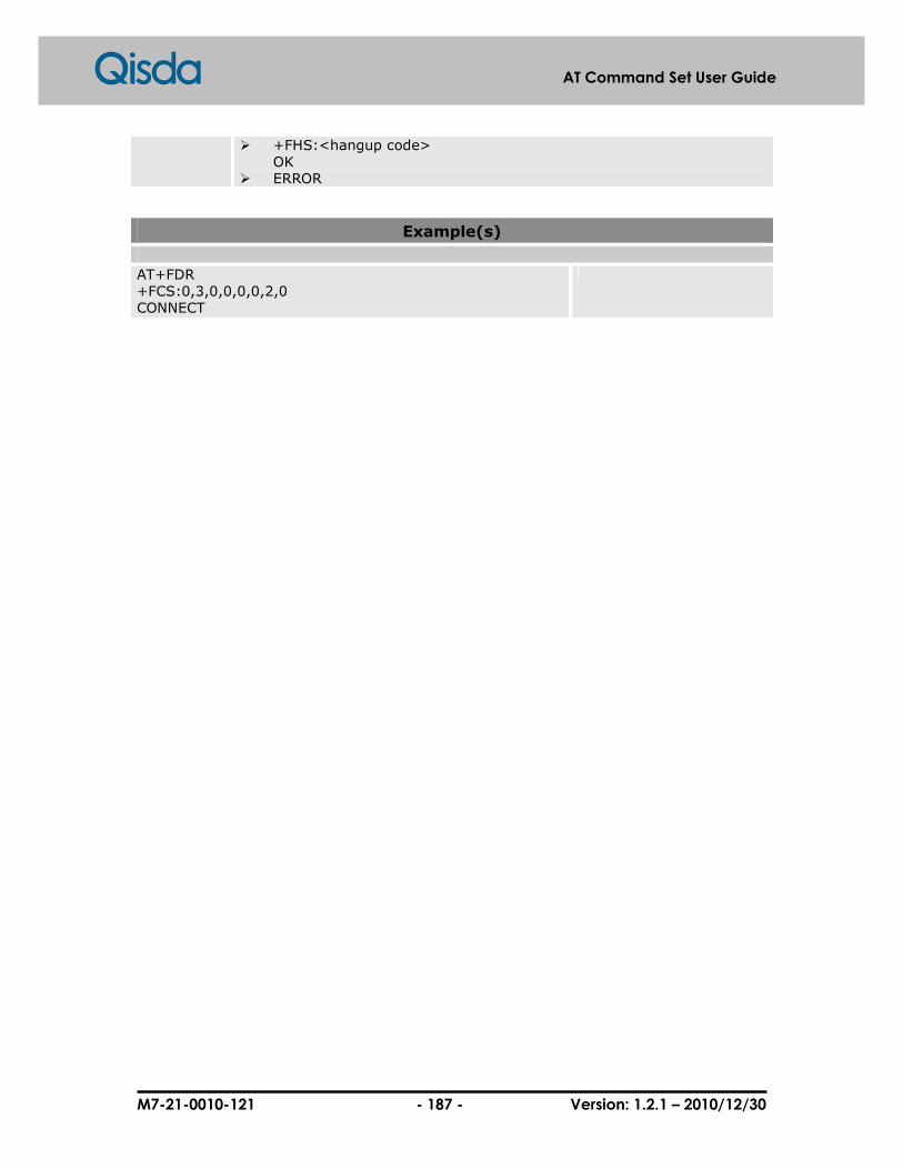
M7-21-0010-121 - 187 - Version: 1.2.1 – 2010/12/30
AT Command Set User Guide
� +FHS:<hangup code> OK
� ERROR
Example(s)
AT+FDR +FCS:0,3,0,0,0,0,2,0 CONNECT

M7-21-0010-121 - 188 - Version: 1.2.1 – 2010/12/30
AT Command Set User Guide
8.3 +FKS: Terminate a session, orderly fax abort
The +FKS command causes the DCE to terminate the session in an orderly manner. In
particular, it will send a DCN message at the next opportunity and hang up. At the
end of the termination process, the DCE shall report the +FHS response with result
code, defined in 8.4.5,/T.32 (http://www.itu.int/rec/T-REC-T/e), go On-Hook and set
FCLASS0 if FCLASS0 is supported.
The DTE may also invoke this operation using the T.50 <CAN> (Cancel, T.50 1/8)
character during Phase C data reception (see 8.3.4.7/T.32). If the DTE issues this
command while the DCE is On-Hook, the DCE shall report OK.
Syntax
AT+FKS
Response(s) � +FHS:<hangup code> OK
� ERROR

M7-21-0010-121 - 189 - Version: 1.2.1 – 2010/12/30
AT Command Set User Guide
8.4 +FIP: Initialize service class 2 parameters
The +FIP command causes the DCE to initiate all Service Class 2 Facsimile Parameters
to the manufacturer who determined default settings. This command does not
change the setting of +FCLASS. This command has the same effect as if the DTE had
issued individual parameter setting commands.
This command may be issued during a session. The DCE shall use the new settings
they are sampled next time; for example, a new + FIS setting would be used next
time the DCE enters Phase B.
Syntax
AT+FIP[=<value>]
Response(s) � OK � +CME ERROR: <err>
Parameter(s)
<value> Not support and always set 0. Numeric
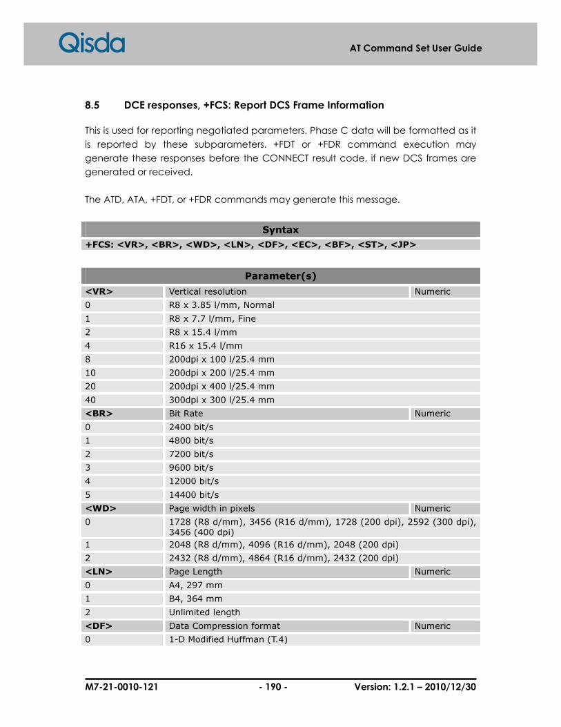
M7-21-0010-121 - 190 - Version: 1.2.1 – 2010/12/30
AT Command Set User Guide
8.5 DCE responses, +FCS: Report DCS Frame Information
This is used for reporting negotiated parameters. Phase C data will be formatted as it
is reported by these subparameters. +FDT or +FDR command execution may
generate these responses before the CONNECT result code, if new DCS frames are
generated or received.
The ATD, ATA, +FDT, or +FDR commands may generate this message.
Syntax
+FCS: <VR>, <BR>, <WD>, <LN>, <DF>, <EC>, <BF>, <ST>, <JP>
Parameter(s)
<VR> Vertical resolution Numeric
0 R8 x 3.85 l/mm, Normal
1 R8 x 7.7 l/mm, Fine
2 R8 x 15.4 l/mm
4 R16 x 15.4 l/mm
8 200dpi x 100 l/25.4 mm
10 200dpi x 200 l/25.4 mm
20 200dpi x 400 l/25.4 mm
40 300dpi x 300 l/25.4 mm
<BR> Bit Rate Numeric
0 2400 bit/s
1 4800 bit/s
2 7200 bit/s
3 9600 bit/s
4 12000 bit/s
5 14400 bit/s
<WD> Page width in pixels Numeric
0 1728 (R8 d/mm), 3456 (R16 d/mm), 1728 (200 dpi), 2592 (300 dpi), 3456 (400 dpi)
1 2048 (R8 d/mm), 4096 (R16 d/mm), 2048 (200 dpi)
2 2432 (R8 d/mm), 4864 (R16 d/mm), 2432 (200 dpi)
<LN> Page Length Numeric
0 A4, 297 mm
1 B4, 364 mm
2 Unlimited length
<DF> Data Compression format Numeric
0 1-D Modified Huffman (T.4)

M7-21-0010-121 - 191 - Version: 1.2.1 – 2010/12/30
AT Command Set User Guide
<EC> Error Correction Numeric
0 Disable ECM
<BF> File Transfer Numeric
0 Disable file transfer modes
<ST> Scan Time/Line Numeric
0 0 ms (VR=0), 0 ms (VR>0)
1 5 ms (VR=0), 5 ms (VR>0)
2 10 ms (VR=0), 5 ms (VR>0)
3 10 ms (VR=0), 10 ms (VR>0)
4 20 ms (VR=0), 10 ms (VR>0)
5 20 ms (VR=0), 20 ms (VR>0)
6 40 ms (VR=0), 20 ms (VR>0)
7 40 ms (VR=0), 40 ms (VR>0)
<JP> JPEG for color and B&W Numeric
0 Disable JPEG coding
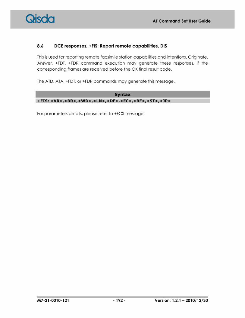
M7-21-0010-121 - 192 - Version: 1.2.1 – 2010/12/30
AT Command Set User Guide
8.6 DCE responses, +FIS: Report remote capabilities, DIS
This is used for reporting remote facsimile station capabilities and intentions. Originate,
Answer, +FDT, +FDR command execution may generate these responses, if the
corresponding frames are received before the OK final result code.
The ATD, ATA, +FDT, or +FDR commands may generate this message.
Syntax
+FIS: <VR>,<BR>,<WD>,<LN>,<DF>,<EC>,<BF>,<ST>,<JP>
For parameters details, please refer to +FCS message.

M7-21-0010-121 - 193 - Version: 1.2.1 – 2010/12/30
AT Command Set User Guide
8.7 DCE responses, +FPI: Report remote ID,CIG
The response reports the received remote polling station ID string, if any. Originate,
Answer, +FDT or +FDR command execution may generate these responses, if the
corresponding frames are received.
The DCE shall report the characters mentioned in the ID string in reverse time order
from the order received from the remote station.
The ATD, ATA, +FDT, or +FDR commands may generate this message.
Syntax
+FPI: <CIG ID string>
Parameter(s)
<CIG ID string> String
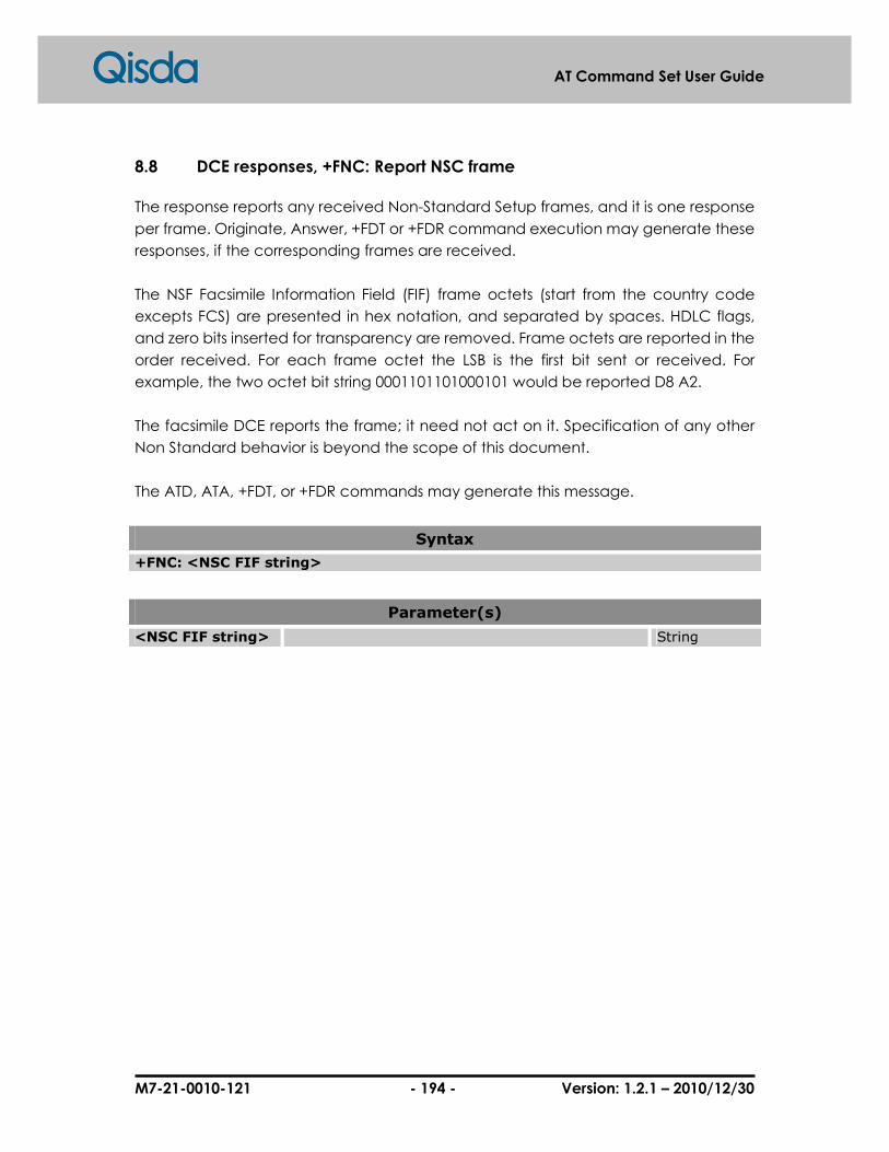
M7-21-0010-121 - 194 - Version: 1.2.1 – 2010/12/30
AT Command Set User Guide
8.8 DCE responses, +FNC: Report NSC frame
The response reports any received Non-Standard Setup frames, and it is one response
per frame. Originate, Answer, +FDT or +FDR command execution may generate these
responses, if the corresponding frames are received.
The NSF Facsimile Information Field (FIF) frame octets (start from the country code
excepts FCS) are presented in hex notation, and separated by spaces. HDLC flags,
and zero bits inserted for transparency are removed. Frame octets are reported in the
order received. For each frame octet the LSB is the first bit sent or received. For
example, the two octet bit string 0001101101000101 would be reported D8 A2.
The facsimile DCE reports the frame; it need not act on it. Specification of any other
Non Standard behavior is beyond the scope of this document.
The ATD, ATA, +FDT, or +FDR commands may generate this message.
Syntax
+FNC: <NSC FIF string>
Parameter(s)
<NSC FIF string> String

M7-21-0010-121 - 195 - Version: 1.2.1 – 2010/12/30
AT Command Set User Guide
8.9 DCE responses, +FNF: Report NSF frame
Please refer to +FNC message.
The ATD, ATA, +FDT, or +FDR commands may generate this message.
Syntax
+FNF: <NSF FIF string>
Parameter(s)
<NSF FIF string> String
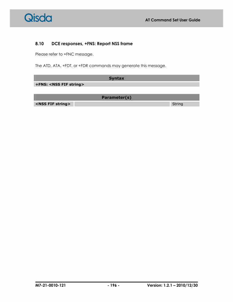
M7-21-0010-121 - 196 - Version: 1.2.1 – 2010/12/30
AT Command Set User Guide
8.10 DCE responses, +FNS: Report NSS frame
Please refer to +FNC message.
The ATD, ATA, +FDT, or +FDR commands may generate this message.
Syntax
+FNS: <NSS FIF string>
Parameter(s)
<NSS FIF string> String

M7-21-0010-121 - 197 - Version: 1.2.1 – 2010/12/30
AT Command Set User Guide
8.11 DCE responses, +FPW: Report password
The response reports the received password string, if any. Originate, Answer, +FDT or
+FDR command execution may generate these responses, if the corresponding
frames are received.
If the corresponding subparameter in the +FAP parameter is set, the DCE shall report
the characters mentioned in the string in reverse time order from the order received
from the remote station. For example, if the following hexadecimal Password string is
received:
<39><38><37><36><35><34><33><32><31><30><39><38><37><36><35><34><33><32
><31> <30>
The result would be:
+FPW: "01234567890123456789"
The ATD, ATA, +FDT, or +FDR commands may generate this message.
Syntax
+FPW: <PWD string>
Parameter(s)
<PWD string> String

M7-21-0010-121 - 198 - Version: 1.2.1 – 2010/12/30
AT Command Set User Guide
8.12 DCE responses, +FSA: Report destination subaddress
The response reports the received destination subaddress string, if any. Originate,
Answer, +FDT or +FDR command execution may generate these responses, if the
corresponding frames are received.
The ATD, ATA, +FDT, or +FDR commands may generate this message.
Syntax
+FSA: <SUB string>
Parameter(s)
<SUB string> String
M7-21-0010-121 - 199 - Version: 1.2.1 – 2010/12/30
AT Command Set User Guide
8.13 DCE responses, +FPA: Report polling address
The response reports the received polling address string, if any. Originate, Answer,
+FDT or +FDR command execution may generate these responses, if the
corresponding frames are received.
The ATD, ATA, +FDT, or +FDR commands may generate this message.
Syntax
+FPA: <SEP string>
Parameter(s)
<SEP string> String

M7-21-0010-121 - 200 - Version: 1.2.1 – 2010/12/30
AT Command Set User Guide
8.14 DCE responses, +FPS: Report T.30 phase C page reception
The +FPS:<ppr> is generated by the DCE at the end of Phase C data reception within
the execution of a +FDR command.
The initial <ppr> is generated by the DCE; it depends on the DCE for T.4 or T.6 error
checking capabilities, controlled by the +FCQ parameter (8.5.2.3/T.32). Note that the
<ppr> value may be changed by the DCE in response to a remote request for
procedure interrupt (8.5.2.2/T.32).
The receiving DCE may count lines, bad lines, maximum consecutive bad lines, and
octets lost due to DCE buffer overflow, and report them:
<lc>: line count;
<blc>: bad line count;
<cblc>: maximum consecutive bad line count; this is the number of lines in the largest
group of consecutive bad lines;
<lbc>: lost octet count.
The line counts are qualified by the DCE’s copy quality checking capabilities,
controlled by the +FCQ parameter (8.5.2.3/T.32). If the DCE is not configured to count
lines, or if line counts are irrelevant (e.g. in Binary File Transfer mode,
Recommendation T.434) the DCE shall set the line counts to 0.
A receiving DTE may inspect <ppr>, and write a modified value into the +FPS
parameter. The DCE shall hold the corresponding Post Page Response message until
it is released by a subsequent +FDR command from the DTE.
Syntax
+FPS: <ppr>, <lc>, <blc>, <cblc>, <lbc>
Parameter(s)
<ppr> Numeric
1 Page good. (T.30 label: MCF; Result code: OK)
2 Page bad, retrain requested. (T.30 label: RTN; Result code: ERROR)
3 Page good, retrain requested. (T.30 label: RTP; Result code: OK)
4 Page good, remote request for procedure interrupt accepted .(T.30 label: PIP; Result code: OK)
5 Page bad, retrain requested; remote request for procedure interrupt accepted. (T.30 label: PIN; Result code: ERROR)
<lc> Line count. Numeric

M7-21-0010-121 - 201 - Version: 1.2.1 – 2010/12/30
AT Command Set User Guide
<blc> Bad line count, reports the number of bad lines set. Numeric
<cblc> Consecutive bad line count: reports the number of consecutive bad lines sent.
Numeric
<lbc> Lost byte count, reports the number of lost bytes Numeric

M7-21-0010-121 - 202 - Version: 1.2.1 – 2010/12/30
AT Command Set User Guide
8.15 DCE responses, +FHS: Call termination status
+FHS indicates that the call has been terminated. The hangup cause is reported, and
stored in the +FHS parameter for later inspection.
+FHS:<hsc> is a possible intermediate result code to any DTE action command
described in 8.3/T.32. It is always followed by the OK final result code.
All <hsc> codes are two-digit hexadecimal values. The <hsc> values are organized
according to the Phases of the facsimile transaction as defined by Recommendation
T.30.
Syntax
+FHS: <hsc>
Parameter(s)
<hsc> Hangup status code Hexadecimal
00-0F Call placement and termination
00 Normal and proper end of connection.
01 Ring detect without successful handshake.
02 Call aborted.
03 No loop current.
04 Ringback detected, no answer (timeout).
05 Ringback detected, answer without CED.
10-1F Transmit Phase A and miscellaneous errors
10 Unspecified Phase A error.
11 No answer (T.30 T1 timeout).
20-3F Transmit Phase B hangup codes
20 Unspecified transmit Phase B error.
21 Remote cannot receive or send.
22 COMREC error in transmit Phase B.
23 COMREC invalid command received.
24 RSPREC error.
25 DCS sent three times without response.
26 DIS/DTC received 3 times; DCS not recognized.
27 Failure to train at 2400 bit/s or +FMS value.
28 RSPREC invalid response received.
40-4F Transmit Phase C hangup codes
40 Unspecified transmit Phase C error.
41 Unspecified image format error.

M7-21-0010-121 - 203 - Version: 1.2.1 – 2010/12/30
AT Command Set User Guide
42 Image conversion error.
43 DTE to DCE data underflow.
44 Unrecognized transparent data command.
45 Image error, line length wrong.
46 Image error, page length wrong.
47 Image error, wrong compression code.
50-6F Transmit Phase D hangup codes
50 Unspecified transmit Phase D error.
51 RSPREC error.
52 No response to MPS repeated 3 times.
53 Invalid response to MPS.
54 No response to EOP repeated 3 times.
55 Invalid response to EOP.
56 No response to EOM repeated 3 times.
57 Invalid response to EOM.
58 Unable to continue after PIN or PIP.
70-8F Receive Phase B hangup codes
70 Unspecified receive Phase B error.
71 RSPREC error.
72 COMREC error.
73 T.30 T2 timeout, expected page not received.
74 T.30 T1 timeout after EOM received.
90-9F Receive Phase C hangup codes
90 Unspecified receive Phase C error.
91 Missing EOL after 5 seconds (3.2/T.4).
92 Bad CRC or frame(ECM mode).
93 DCE to DTE buffer overflow.
A0-BF Receive Phase D hangup codes
A0 Unspecified receive Phase D errors.
A1 RSPREC invalid response received.
A2 COMREC invalid response received.
A3 Unable to continue after PIN or PIP.
C0-DF Reserved for future standardization
E0-FF Reserved for manufacturer-specific use

M7-21-0010-121 - 204 - Version: 1.2.1 – 2010/12/30
AT Command Set User Guide
8.16 +FCLASS: Service class identification and control
Set command puts the TA into a particular mode of operation (data, fax, voice etc.).
This causes the TA to process information in a manner suitable for that type of
information (rather than for other types of information).
Query command returns current Service Class settings of a Facsimile DCE. The
response shall be a single value.
Test command returns available Service Classes of a Facsimile DCE. The response is a
string of values, separated by commas, followed by a result code.
Syntax
AT+FCLASS=<n>
Response(s) � OK � ERROR
AT+FCLASS?
Response(s) � <n> OK
AT+FCLASS=?
Response(s) � (list of supported(<n>) OK
Parameter(s)
<n> Service class.
0 Data modem (ITU-T Rec. V.250).
2.0 Fax class 2.0(ITU-T Rec. T.32).
8 Voice
M7-21-0010-121 - 205 - Version: 1.2.1 – 2010/12/30
AT Command Set User Guide
8.17 +FCC: DCE capabilities parameter
+FCC allows the DTE to sense and constrain the capabilities of the facsimile DCE, from
the choices defined in Table 2/T.30 (http://www.itu.int/rec/T-REC-T/e). When +FCC is
modified by the DTE, the DCE shall copy +FCC into +FIS.
Syntax
AT+FCC=<VR>, <BR>, <WD>, <LN>, <DF>, <EC>, <BF>, <ST>, <JP>
Response(s) � OK � ERROR
AT+FCC?
Response(s) � +FCC: <VR>, <BR>, <WD>, <LN>, <DF>, <EC>, <BF>, <ST>, <JP> OK
AT+FCC=?
Response(s) � +FCC: (list of supported <VR>s),(list of supported <BR>s),(list of supported <WD>s),(list of supported <LN>s),(list of supported <DF>s),(list of supported <EC>s),(list of supported <BF>s),(list of supported <ST>s),(list of supported <JP>s) OK
For parameters details, please refer to +FCS message.

M7-21-0010-121 - 206 - Version: 1.2.1 – 2010/12/30
AT Command Set User Guide
8.18 +FIS: Current session parameter
+FIS allows the DTE to sense and constrain the capabilities of current session. The DCE
uses +FIS to generate DIS or DTC messages directly, and uses +FIS together with
received DIS messages to generate DCS messages.
The DCE shall set the FIS parameter from the FCC parameter on DCE initialization
upon FIP command execution, when FCC is written and at the end of a session.
Syntax
AT+FIS=<VR>, <BR>, <WD>, <LN>, <DF>, <EC>, <BF>, <ST>, <JP>
Response(s) � OK � ERROR
AT+FIS?
Response(s) � +FIS: <VR>, <BR>, <WD>, <LN>, <DF>, <EC>, <BF>, <ST>, <JP> OK
AT+FIS=?
Response(s) � +FIS: (list of supported <VR>s),( list of supported <BR>s),( list of supported <WD>s),(list of supported <LN>s),(list of supported <DF>s), (list of supported <EC>s),( list of supported <BF>s),( list of supported <ST>s),(list of supported <JP>s) OK
For parameters details, please refer to +FCS message.

M7-21-0010-121 - 207 - Version: 1.2.1 – 2010/12/30
AT Command Set User Guide
8.19 +FCS: Current session results (Fax class 2.0)
The +FCS parameter is loaded with the negotiated T.30 parameters for the current
session. A transmitting DCE generates DCS; a receiving DCE gets DCS from the
remote station. The DTE may only read this parameter.
The DCE shall set the +FCS parameter to the default values on DCE initialization, on
+FIP command execution, and at the end of a session.
The contents of +FCS are spontaneously reported during execution of +FDR or +FDT
commands by the +FCS: <VR>, <BR>, <WD>, <LN>, <DF>, <EC>, <BF>, <ST>, <JP>
response which usesthe same compound parameter format.
Syntax
AT+FCS?
Response(s) � +FCS: <VR>,<BR>,<WD>,<LN>,<DF>,<EC>,<BF>,<ST>,<JP> OK
For parameters details, please refer to +FCS message.
M7-21-0010-121 - 208 - Version: 1.2.1 – 2010/12/30
AT Command Set User Guide
8.20 +FLI: Local facsimile station ID string, TSI/CSI
To sets the local ID string used by the remote station to identify the originating station.
Syntax
AT+FLI=<local ID string>
Response(s) � OK � +CME ERROR: <err>
AT+FLI?
Response(s) � +FLI: <local ID string> OK
AT+FLI=?
Response(s) � +FIS: (list of the range of supported characters with hexadecimal) OK
Parameter(s)
<local ID string> String

M7-21-0010-121 - 209 - Version: 1.2.1 – 2010/12/30
AT Command Set User Guide
8.21 +FPI: Local facsimile station ID, CIG(local Polling ID)
This is used by the remote station to identify the originating station.
Syntax
AT+FPI=<local polling ID string>
Response(s) � OK � +CME ERROR: <err>
AT+FPI?
Response(s) � +FPI: <local polling ID string> OK
AT+FPI=?
Response(s) � +FPI: (list of the range of supported characters with hexadecimal) OK
Parameter(s)
<local polling ID string> String
M7-21-0010-121 - 210 - Version: 1.2.1 – 2010/12/30
AT Command Set User Guide
8.22 +FNS: Pass-through non-standard negotiation byte string
The DCE shall send the corresponding non-standard facilities frame if +FNS is not a null
string. The type of frame is determined by the type of negotiation frame and can be
sent for NSF sent with DIS; NSS sent with DCS; NSC sent with DTC.
The DCE only delivers the data; the DTE must determine the content. The first octet
must be the country code (see Recommendation T.35). This parameter may require
180 hexadecimal characters for specifying. The +FNS= <hex string> may be repeated
with new data which will be appended to the data entered previously. The +FNS=""
command resets this parameter to a null string.
The <hexadecimal coded octet string> shall consist of pairs of hexadecimal numbers
(T.50 3/0-3/9, 4/1-4/6). Spaces between octets shall be ignored by the DCE. The DCE
shall send octets in the order loaded. Each octet shall be sent LSB first; the string
"D8A2" would result in the following bit pattern: 0001101101000101. (Note – This is the
same format used in Non-Standard frame reports, see 8.4.2.4/T.32.)
Syntax
AT+FNS=<string of hexadecimal coded octets>
Response(s) � OK � ERROR: <err>
AT+FNS?
Response(s) � +FNS: <string of hexadecimal coded octets> OK
AT+FNS=?
Response(s) � +FNS: (number of octets that the parameter can hold) OK
Parameter(s)
<string of hexadecimal coded octets> With hexadecimal format String
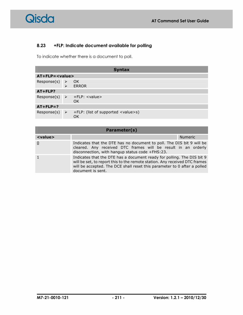
M7-21-0010-121 - 211 - Version: 1.2.1 – 2010/12/30
AT Command Set User Guide
8.23 +FLP: Indicate document available for polling
To indicate whether there is a document to poll.
Syntax
AT+FLP=<value>
Response(s) � OK � ERROR
AT+FLP?
Response(s) � +FLP: <value> OK
AT+FLP=?
Response(s) � +FLP: (list of supported <value>s) OK
Parameter(s)
<value> Numeric
0 Indicates that the DTE has no document to poll. The DIS bit 9 will be cleared. Any received DTC frames will be result in an orderly disconnection, with hangup status code +FHS:23.
1 Indicates that the DTE has a document ready for polling. The DIS bit 9 will be set, to report this to the remote station. Any received DTC frames will be accepted. The DCE shall reset this parameter to 0 after a polled document is sent.
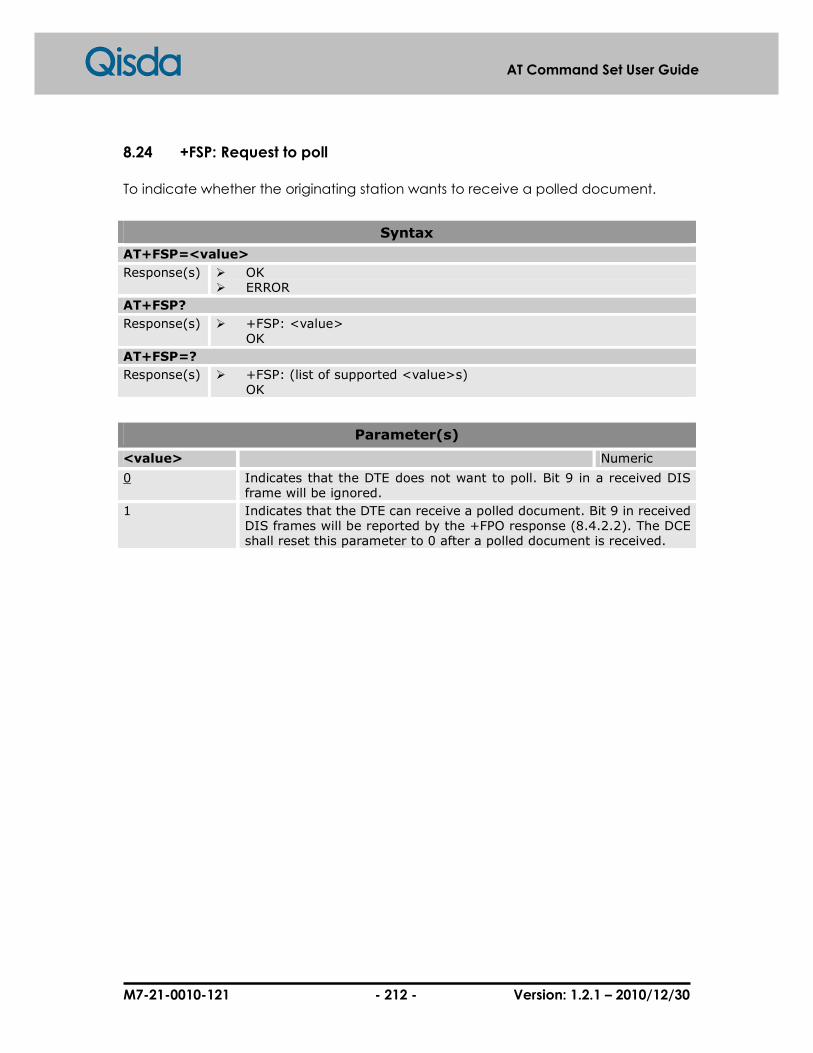
M7-21-0010-121 - 212 - Version: 1.2.1 – 2010/12/30
AT Command Set User Guide
8.24 +FSP: Request to poll
To indicate whether the originating station wants to receive a polled document.
Syntax
AT+FSP=<value>
Response(s) � OK � ERROR
AT+FSP?
Response(s) � +FSP: <value> OK
AT+FSP=?
Response(s) � +FSP: (list of supported <value>s) OK
Parameter(s)
<value> Numeric
0 Indicates that the DTE does not want to poll. Bit 9 in a received DIS frame will be ignored.
1 Indicates that the DTE can receive a polled document. Bit 9 in received DIS frames will be reported by the +FPO response (8.4.2.2). The DCE shall reset this parameter to 0 after a polled document is received.

M7-21-0010-121 - 213 - Version: 1.2.1 – 2010/12/30
AT Command Set User Guide
8.25 +FCR: Capability to receive
To enable or disable fax reception.
Syntax
AT+FCR=<value>
Response(s) � OK � ERROR
AT+FCR?
Response(s) � +FCR: <value> OK
AT+FCR=?
Response(s) � +FCR: (list of supported <value>s) OK
Parameter(s)
<value> Numeric
0 Indicates the DCE will not receive message data; also, the DCE will not be able to poll a remote device. This clears bit 10 in the DIS or DTC frame. This can be used when the DTE has insufficient storage, or if the DCE does not have a Phase C demodulator. The DCE can send and can be polled for a document.
1 Indicates the DCE can receive message data. Bit 10 in the DIS or DTC frame will be set.
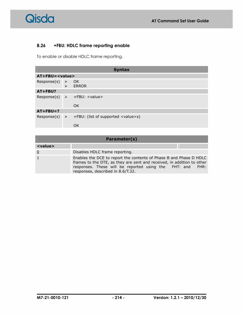
M7-21-0010-121 - 214 - Version: 1.2.1 – 2010/12/30
AT Command Set User Guide
8.26 +FBU: HDLC frame reporting enable
To enable or disable HDLC frame reporting.
Syntax
AT+FBU=<value>
Response(s) � OK � ERROR
AT+FBU?
Response(s) � +FBU: <value> OK
AT+FBU=?
Response(s) � +FBU: (list of supported <value>s) OK
Parameter(s)
<value>
0 Disables HDLC frame reporting.
1 Enables the DCE to report the contents of Phase B and Phase D HDLC frames to the DTE, as they are sent and received, in addition to other responses. These will be reported using the FHT: and FHR: responses, described in 8.6/T.32.
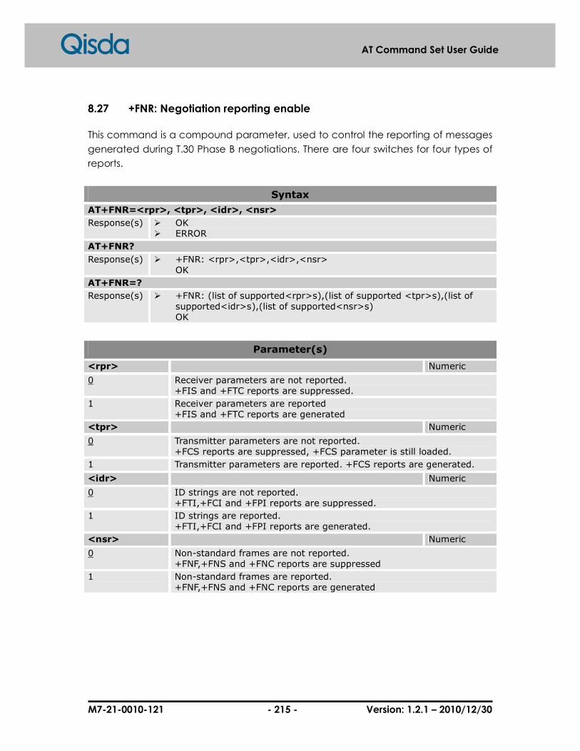
M7-21-0010-121 - 215 - Version: 1.2.1 – 2010/12/30
AT Command Set User Guide
8.27 +FNR: Negotiation reporting enable
This command is a compound parameter, used to control the reporting of messages
generated during T.30 Phase B negotiations. There are four switches for four types of
reports.
Syntax
AT+FNR=<rpr>, <tpr>, <idr>, <nsr>
Response(s) � OK � ERROR
AT+FNR?
Response(s) � +FNR: <rpr>,<tpr>,<idr>,<nsr> OK
AT+FNR=?
Response(s) � +FNR: (list of supported<rpr>s),(list of supported <tpr>s),(list of supported<idr>s),(list of supported<nsr>s) OK
Parameter(s)
<rpr> Numeric
0 Receiver parameters are not reported. +FIS and +FTC reports are suppressed.
1 Receiver parameters are reported +FIS and +FTC reports are generated
<tpr> Numeric
0 Transmitter parameters are not reported. +FCS reports are suppressed, +FCS parameter is still loaded.
1 Transmitter parameters are reported. +FCS reports are generated.
<idr> Numeric
0 ID strings are not reported. +FTI,+FCI and +FPI reports are suppressed.
1 ID strings are reported. +FTI,+FCI and +FPI reports are generated.
<nsr> Numeric
0 Non-standard frames are not reported. +FNF,+FNS and +FNC reports are suppressed
1 Non-standard frames are reported. +FNF,+FNS and +FNC reports are generated

M7-21-0010-121 - 216 - Version: 1.2.1 – 2010/12/30
AT Command Set User Guide
8.28 +FAP: Address & polling capabilities
This command indicates inbound subaddressing, selective polling and password
capabilities to remote station via the corresponding bits in the DIS or DTC frames.
Syntax
AT+FAP=<sub>, <sep>, <pwd>
Response(s) � OK � ERROR
AT+FAP?
Response(s) � +FAP: <sub>, <sep>, <pwd> OK
AT+FAP=?
Response(s) � +FAP: (list of supported <sub>s),(list of supported <sep>s),(list of supported <pwd>s) OK
Parameter(s)
<sub> Subaddressing capability Numeric
0 Disable
1 Enable
<sep> Selective polling capability Numeric
0 Disable
1 Enable
<pwd> Password capability Numeric
0 Disable
1 Enable
M7-21-0010-121 - 217 - Version: 1.2.1 – 2010/12/30
AT Command Set User Guide
8.29 +FSA: Address & polling frame/subaddress
The DCE shall send the numeric string contained in +FSA at the times specified in
Recommendation T.30, if the corresponding parameter is not a null string.
Recommendation T.30 defines these frames for values of digits 0-9, space, * and #
characters only.
The DCE shall transmit digit string characters to the remote station in reversed time
order from the order in the command line. For example, if the command line
AT+FSA="1 012 3456789**01#" is issued, the DCE would add two space characters,
and send a SUB frame with FIF consisting of the following octets (expressed as
hexadecimal digits):
<23><31><30><2A><2A><39><38><37><36><35><34><33><20><32><31><30><20><3
1><20><20>
If less than 20 characters are specified in a non-null string, the DCE shall append
space characters (2/0). If the specified string is more than 20 characters, an ERROR
result code is generated.
Syntax
AT+FSA=<destination subaddress string>
Response(s) � OK � ERROR
AT+FSA?
Response(s) � +FSA: <destination subaddress string> OK
AT+FSA=?
Response(s) � +FSA: (list of supported characters) OK
Parameter(s)
<destination subaddress string> Should less than 20 octets. String

M7-21-0010-121 - 218 - Version: 1.2.1 – 2010/12/30
AT Command Set User Guide
8.30 +FPA: Address & polling frame/polling address
The DCE shall send the numeric string contained in +FPA at the times specified in
Recommendation T.30, if the corresponding parameter is not a null string.
Recommendation T.30 defines these frames for values of digits 0-9, space, * and #
characters only.
The DCE shall transmit digit string characters to the remote station in reversed time
order from the order in the command line.
If less than 20 characters are specified in a non-null string, the DCE shall append
space characters (2/0). If the specified string is more than 20 characters, an ERROR
result code is generated.
Syntax
AT+FPA=<selective polling address string>
Response(s) � OK � ERROR
AT+FPA?
Response(s) � +FPA: <selective polling address string> OK
AT+FPA=?
Response(s) � +FPA: (list of supported characters) OK
Parameter(s)
< selective polling address string> Should less than 20 octets. String

M7-21-0010-121 - 219 - Version: 1.2.1 – 2010/12/30
AT Command Set User Guide
8.31 +FPW: Address & polling frame/password
The DCE shall send the numeric string contained in +FPW at the times specified in
Recommendation T.30, if the corresponding parameter is not a null string. The +FPW
parameter is used for the PWD frame sent with either DTC or DCS. Recommendation
T.30 defines these frames for values of digits 0-9, space, * and # characters only.
The DCE shall transmit digit string characters to the remote station in reversed time
order from the order in the command line.
If less than 20 characters are specified in a non-null string, the DCE shall append
space characters (2/0). If the specified string is more than 20 characters, an ERROR
result code is generated.
Syntax
AT+FPW=<password string>
Response(s) � OK � ERROR
AT+FPW?
Response(s) � +FPW: <password string> OK
AT+FPW=?
Response(s) � +FPW: (list of supported characters) OK
Parameter(s)
<password string> String should less than 20 octets. String
M7-21-0010-121 - 220 - Version: 1.2.1 – 2010/12/30
AT Command Set User Guide
8.32 +FIE: Procedure interrupt enable
This command decides the operation upon receipts Procedure Interrupt Requests
from remote station.
For transmission (+FDT), Procedure Interrupt Requests from the remote station are not
reported directly; only the +FVO response is reported.
For reception (+FDR), Procedure Interrupt Requests from the remote station are
reported in the +FET: response. The value stored in the +FPS parameter will be
adjusted to 4 or 5. If the DTE issues a subsequent +FDR command with the +FPS value
intact, the DCE will complete the negotiation and issue a +FVO response.
Syntax
AT+FIE=<value>
Response(s) � OK � ERROR
AT+FIE?
Response(s) � +FIE: <value> OK
AT+FIE=?
Response(s) � +FIE: (list of supported <value>s) OK
Parameter(s)
<value> Numeric
0 Procedure Interrupt Requests from the remote station are ignored, and not reported to the DTE. For the +FET: response (8.4.4.1/T.32), PRI-Q reports will be replaced by non-PRI equivalents.
1 Procedure Interrupt Requests from the remote station are accepted, negotiated and reported using the +FVO response (8.4.4.2/T.32)

M7-21-0010-121 - 221 - Version: 1.2.1 – 2010/12/30
AT Command Set User Guide
8.33 +FPS: Page status
The +FPS parameter which contains a value represents the post page response, and it
also includes copy quality and related end-of-page status. These values correspond
to post page response messages defined in Recommendation T.30. The receiving
DCE sets this parameter after it receives a page of Phase C data. The transmitting
DCE sets this parameter with the status reported by the receiving station. The DTE may
inspect or modify this parameter.
Valid <ppr> is defined below. Its value is also reported by the +FPS:<ppr> response to
the +FDR command (8.4.3/T.32).
The DCE may set this parameter to values 1, 2 or 3 based on its own copy quality
checking or access to received signal quality. The DCE shall set this parameter to a
value of 1 if copy quality checking is disabled (+FCQ=0, see 8.5.2.3/T.32).
Copy quality checking is the responsibility of the DCE. However, a receiving DTE may
do its own Copy Quality checking.
The DTE may request a Procedure Interrupt from the remote station using this
parameter. To do so, the DTE shall modify the value reported by the DCE before it
issues the next +FDR command, which in turn instructs the DCE to send the resulting
post page response to the remote facsimile station.
Syntax
AT+FPS=<ppr>
Response(s) � OK � ERROR
AT+FPS?
Response(s) � +FPS: <ppr> OK
AT+FPS=?
Response(s) � +FPS: (list of supported <ppr>s) OK
Parameter(s)
<ppr> Post page response Numeric
1 Page good (T.30 label: MCF; Result code: OK)
2 Page bad; retrain requested (T.30 label: RTN; Result code: ERROR)
3 Page good; retrain requested (T.30 label: RTP; Result code: OK)
4 Page good; remote request for procedure interrupt accepted (T.30 label:

M7-21-0010-121 - 222 - Version: 1.2.1 – 2010/12/30
AT Command Set User Guide
PIP; Result code: OK)
5 Page bad; retrain requested; remote request for procedure interrupt accepted (T.30 label: PIN; Result code: ERROR)

M7-21-0010-121 - 223 - Version: 1.2.1 – 2010/12/30
AT Command Set User Guide
8.34 +FCQ: Copy quality checking
The +FCQ compound parameter controls copy quality checking and correction by a
facsimile DCE. The <rq> subparameter controls copy quality checking and correction
of data which is received from the remote station and delivered to the local DTE; the
<tq> subparameter controls copy quality checking and correction of image data
which is received from the local DTE and sent to the remote facsimile station.
For any data type supported, DCE is responsible for Receive Copy Quality Checking.
However, the DTE may turn off copy quality checking by setting +FCQ=0,0, or by
setting +FND=1.
Copy quality checking consists of determining if the incoming image data conforms
to the negotiated standard format, e.g. Recommendation T.4 or T.6. Copy quality
correction consists of detecting errors and altering the data in some way to
guarantee that only valid data (according to negotiated parameters) is delivered.
The methods used for copy quality checking or for correction are not a subject of T.32.
The DCE may use the associated T.30 control parameters to condition its Copy Quality
Checking behavior. Common procedures for Copy Quality correction include
deletion of bad lines or replacement of bad lines by previous good lines.
The DCE shall report on Received Copy Quality to the DTE in the page status report,
+FPS:<ppr>,<lc>,<blc>,<cblc>,<lbc>, and record it in the +FPS parameter.
Syntax
AT+FCQ=<rq>,<tq>
Response(s) � OK � ERROR
AT+FCQ?
Response(s) � +FCQ: <rq>,<tq> OK
AT+FCQ=?
Response(s) � +FCQ: (list of supported <rq>s),(list of supported <tq>s) OK
Parameter(s)
<rq> Receive quality check Numeric
0 Receive checking disabled; +FPS is set to 1.
1 Receive checking enabled.
2 Receive checking enabled. Modem detects and correct errors.

M7-21-0010-121 - 224 - Version: 1.2.1 – 2010/12/30
AT Command Set User Guide
<tq> Transmit quality check Numeric
0 Transmit checking disabled.
1 Transmit checking enabled; modem sends <CAN> following any errors.
2 Transmit checking enabled; modem detects and corrects errors.

M7-21-0010-121 - 225 - Version: 1.2.1 – 2010/12/30
AT Command Set User Guide
8.35 +FRQ: Receive quality checking
The DCE may use this compound parameter to make the "Copy Quality OK" decision
in the T.30 flow chart (Figure A.7/T.30). If this is used, the DCE shall judge Copy Quality
that is unacceptable if either the percentage of good lines is too low or too many
consecutive lines contain errors. Bad line counts are reported in the +FPS:<blc>
response, described in 8.4.3/T.32 (http://www.itu.int/rec/T-REC-T/e). A value of 0
disables either subparameter for using in copy quality checking.
Syntax
AT+FRQ=<pgl>,<cbl>
Response(s) � OK � ERROR
AT+FRQ?
Response(s) � +FRQ: <pgl>,<cbl> OK
AT+FRQ=?
Response(s) � +FRQ: (list of supported <pgl>s),(list of supported <cbl>s) OK
Parameter(s)
<pgl> Percentage of good lines Numeric
0 Not support, set 0.
<cbl> Consecutive bad lines Numeric
0 Not support, set 0.

M7-21-0010-121 - 226 - Version: 1.2.1 – 2010/12/30
AT Command Set User Guide
8.36 +FCT: DTE phase C response timeout
The command determines how long the DCE will wait for a command after having
transmitted all available Phase C data.
For transmission (+FDT), the DCE shall properly terminate any Phase C data that is
transferred in progress when this timeout is reached. Then DCE will execute an implied
+FKS sequential abort command.
For reception (+FDR), the DCE shall send the T.30 DCN response to the remote station
and execute an implied sequential abort command when this timeout is reached.
Syntax
AT+FCT=<value>
Response(s) � OK � ERROR
AT+FCT?
Response(s) � +FCT: <value> OK
AT+FCT=?
Response(s) � +FCT: (list of supported <value>s) OK
Parameter(s)
<value> Hexadecimal
1E 30 seconds, not configurable.

M7-21-0010-121 - 227 - Version: 1.2.1 – 2010/12/30
AT Command Set User Guide
8.37 +FHS : Call termination status
This read-only parameter indicates the cause of a hang up. Parameter shows the
valid values for this parameter as well as the meaning of each value. +FHS is set by
the DCE at the conclusion of a fax session. The DCE shall reset this parameter to 0 at
the beginning of Phase A.
Syntax
AT+FHS?
Response(s) � +FHS: <hsc> OK
For parameters details, please refer to +FHS message.

M7-21-0010-121 - 228 - Version: 1.2.1 – 2010/12/30
AT Command Set User Guide
8.38 +FMS: Minimum phase c speed
This optional parameter limits the lowest negotiable speed for a session. This
parameter is useful for limiting the cost of a transmission, by requiring a minimum
transmission speed. If the facsimile DCE cannot negotiate to a minimum speed, it shall
perform an sequential disconnection.
Syntax
AT+FMS=<BR>
Response(s) � OK � ERROR
AT+FMS?
Response(s) � +FMS: <BR> OK
AT+FMS=?
Response(s) � +FMS: (list of supported <BR>s) OK
For parameter details, please refer to +FCS message.
M7-21-0010-121 - 229 - Version: 1.2.1 – 2010/12/30
AT Command Set User Guide
8.39 +FIT: Inactivity timeout
A service Class 2 facsimile DCE shall provide an inactivity timer that allows the DCE to
break away from an unsuccessful connection attempt at any stage of a facsimile
transfer. The inactivity timer only works while the DCE is off-hook.
The <time> parameter indicates the inactivity timeout in seconds. The required
timeout is from 1 to 255 seconds. The value of 0 indicates that timeout is disabled. The
<action> parameter has two meanings.
The inactivity timer starts when the DCE has taken some action that requires DTE
response. If the DTE does respond, the DCE shall reset the inactivity timer.
Syntax
AT+FIT=<time>,<action>
Response(s) � OK � ERROR
AT+FIT?
Response(s) � +FRQ:<time>,<action> OK
AT+FIT=?
Response(s) � +FRQ: (list of supported <time>s), (list of supported <action>s) OK
Parameter(s)
<time> Inactivity timeout Numeric
0 Disable
1-255 Enable timeout in seconds.
<action> Numeric
0 Upon timeout, the DCE shall go on-hook, executing an implied ATH command; then reset to +FCLASS=0 if +FCLASS=0 is supported by the DCE
1 Upon timeout, the DCE shall only go on-hook. This feature is used to detect possible system failure, when either no line or DTE activity has occurred for a minimum amount of time
M7-21-0010-121 - 230 - Version: 1.2.1 – 2010/12/30
AT Command Set User Guide
8.40 +FBS: Report buffer size
This parameter allows the DCE to report the size of the DCE’s data buffers. The values
shall be in hexadecimal and represent the buffer size in octets.
The DCE shall provide sufficient receive buffer to accommodate 3 seconds of
flow-control-off at the maximum receive speed; at 9600 bit/s, this is E10h octets (3600
decimal).
Syntax
AT+FBS?
Response(s) � +FBS: <tbs>,<rbs> OK
Parameter(s)
<tbs> Transmit buffer size. Hexadecimal
<rbs> Receive buffer size. Hexadecimal

M7-21-0010-121 - 231 - Version: 1.2.1 – 2010/12/30
AT Command Set User Guide
8.41 +FBO: Data bit order
This parameter controls the mapping between PSTN facsimile data and the DTE-DCE
link. There are two choices:
-Direct – The first bit transferred of each octet on the DTE-DCE link is the first bit
transferred on the GSTN data carrier.
-Reversed – The last bit transferred of each octet on the DTE-DCE link is the first bit
transferred on the GSTN data carrier.
There are two data types to control:
-Phase C data – T.4 or T.6 encoded data, or any other type of data (e.g. T.434 BFT),
transferred during execution of +FDT or +FDR commands.
-Phase B/D data – T.30 Phase B and Phase D control messages that are reported to
the DTE in +FHT: and +FHR: reports only (8.6) as well as enabled by the +FBU parameter
(8.5.1.10/T.32).
Syntax
AT+FBO=<value>
Response(s) � OK � ERROR
AT+FBO?
Response(s) � +FBO:<value> OK
AT+FBO=?
Response(s) � +FBO: (list of supported <value>s) OK
Parameter(s)
<value> Numeric
0 Selects direct bit order for both Phase C data and for Phase B/D data.
1 Selects reversed bit order for Phase C data and selects direct bit order for Phase B/D data.
2 Selects direct bit order for Phase C data and selects reversed bit order for Phase B/D data.
3 Selects reversed bit order for both Phase C data and for Phase B/D data.

M7-21-0010-121 - 232 - Version: 1.2.1 – 2010/12/30
AT Command Set User Guide
8.42 +FEA: Phase C received EOL alignment
This parameter enables optional octet-alignment of EOL markers in received T.4 data
streams. It does not apply to T.6 data, or to any other form of data (e.g. T.434 BFT).
Syntax
AT+FEA=<value>
Response(s) � OK � ERROR
AT+FEA?
Response(s) � +FEA:<value> OK
AT+FEA=?
Response(s) � +FEA: (list of supported <value>s) OK
Parameter(s)
<value> Numeric
0 Determines that T.4 EOL patterns are bit aligned (as received).
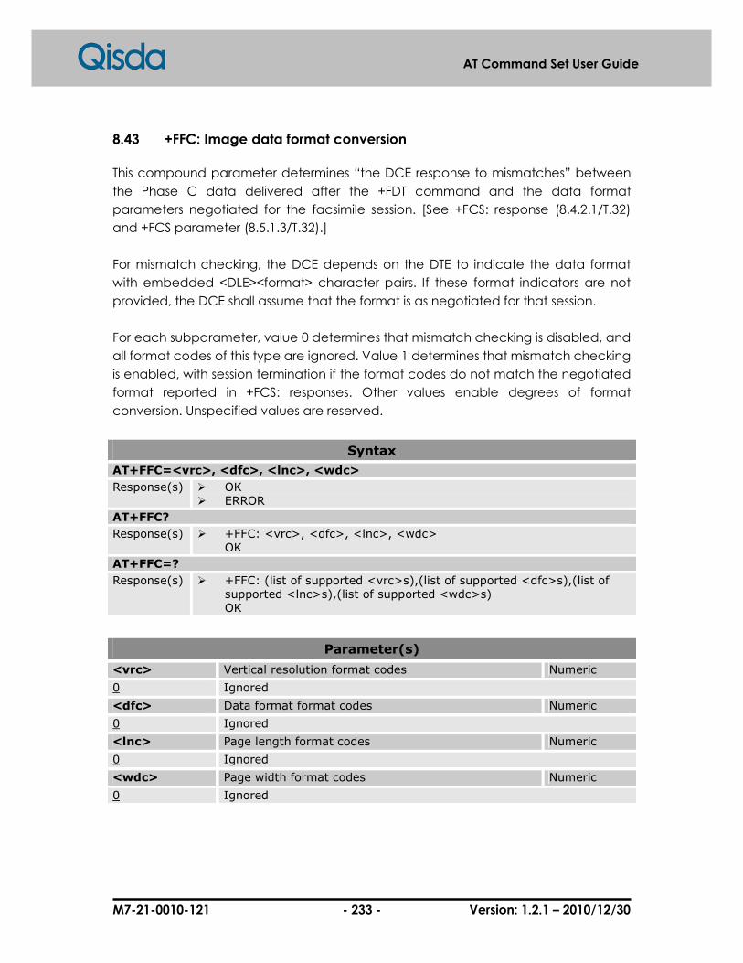
M7-21-0010-121 - 233 - Version: 1.2.1 – 2010/12/30
AT Command Set User Guide
8.43 +FFC: Image data format conversion
This compound parameter determines “the DCE response to mismatches” between
the Phase C data delivered after the +FDT command and the data format
parameters negotiated for the facsimile session. [See +FCS: response (8.4.2.1/T.32)
and +FCS parameter (8.5.1.3/T.32).]
For mismatch checking, the DCE depends on the DTE to indicate the data format
with embedded <DLE><format> character pairs. If these format indicators are not
provided, the DCE shall assume that the format is as negotiated for that session.
For each subparameter, value 0 determines that mismatch checking is disabled, and
all format codes of this type are ignored. Value 1 determines that mismatch checking
is enabled, with session termination if the format codes do not match the negotiated
format reported in +FCS: responses. Other values enable degrees of format
conversion. Unspecified values are reserved.
Syntax
AT+FFC=<vrc>, <dfc>, <lnc>, <wdc>
Response(s) � OK � ERROR
AT+FFC?
Response(s) � +FFC: <vrc>, <dfc>, <lnc>, <wdc> OK
AT+FFC=?
Response(s) � +FFC: (list of supported <vrc>s),(list of supported <dfc>s),(list of supported <lnc>s),(list of supported <wdc>s) OK
Parameter(s)
<vrc> Vertical resolution format codes Numeric
0 Ignored
<dfc> Data format format codes Numeric
0 Ignored
<lnc> Page length format codes Numeric
0 Ignored
<wdc> Page width format codes Numeric
0 Ignored

M7-21-0010-121 - 234 - Version: 1.2.1 – 2010/12/30
AT Command Set User Guide
8.44 +FLO: Flow control
This command controls the mode of DTE-DCE flow control.
Syntax
AT+FLO=<value>
Response(s) � OK � ERROR
AT+FLO?
Response(s) � +FLO: <value> OK
AT+FLO =?
Response(s) � +FLO: (list of supported <value>s) OK
Parameter(s)
<value> DTE-DCE flow control Numeric
0 Turn off flow control
1 DC1/DC3 flow control (software flow control)
2 Circuit 106/133 flow control (hardware flow control)
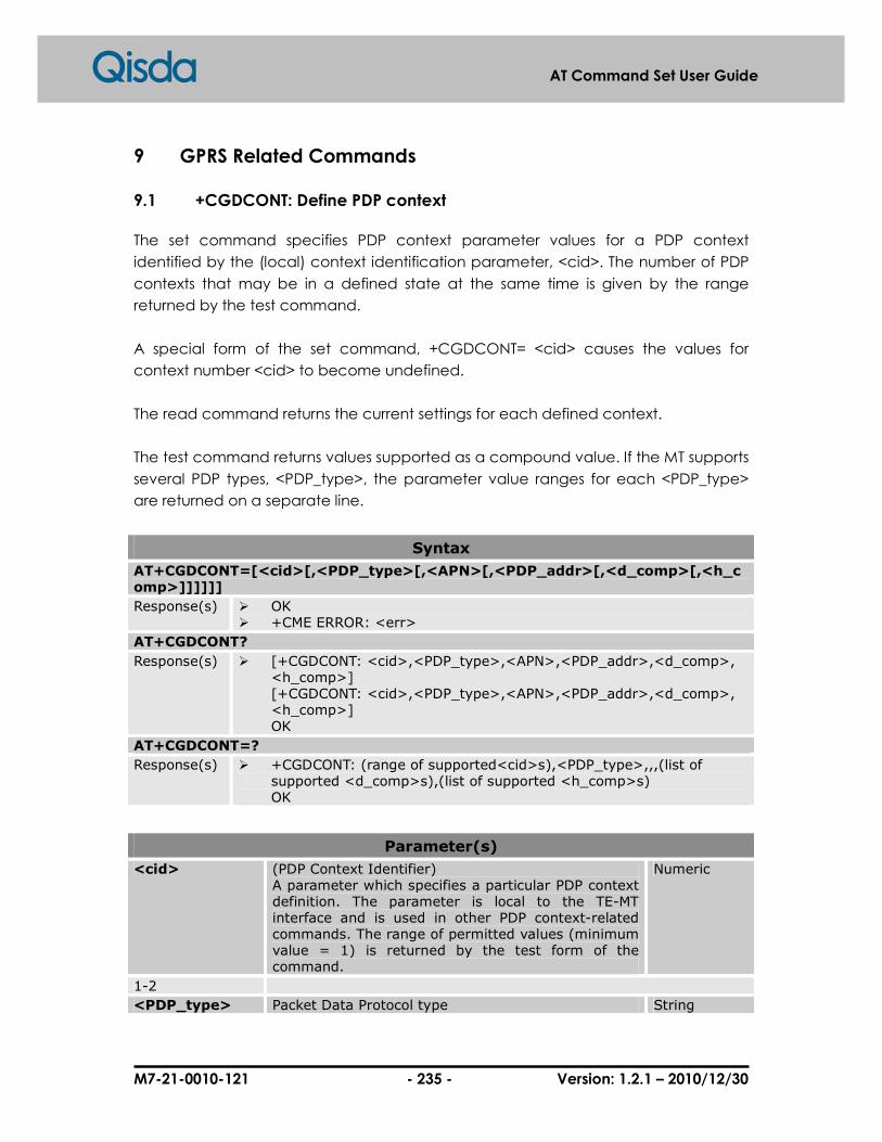
M7-21-0010-121 - 235 - Version: 1.2.1 – 2010/12/30
AT Command Set User Guide
9 GPRS Related Commands
9.1 +CGDCONT: Define PDP context
The set command specifies PDP context parameter values for a PDP context
identified by the (local) context identification parameter, <cid>. The number of PDP
contexts that may be in a defined state at the same time is given by the range
returned by the test command.
A special form of the set command, +CGDCONT= <cid> causes the values for
context number <cid> to become undefined.
The read command returns the current settings for each defined context.
The test command returns values supported as a compound value. If the MT supports
several PDP types, <PDP_type>, the parameter value ranges for each <PDP_type>
are returned on a separate line.
Syntax
AT+CGDCONT=[<cid>[,<PDP_type>[,<APN>[,<PDP_addr>[,<d_comp>[,<h_comp>]]]]]]
Response(s) � OK � +CME ERROR: <err>
AT+CGDCONT?
Response(s) � [+CGDCONT: <cid>,<PDP_type>,<APN>,<PDP_addr>,<d_comp>, <h_comp>] [+CGDCONT: <cid>,<PDP_type>,<APN>,<PDP_addr>,<d_comp>, <h_comp>] OK
AT+CGDCONT=?
Response(s) � +CGDCONT: (range of supported<cid>s),<PDP_type>,,,(list of supported <d_comp>s),(list of supported <h_comp>s) OK
Parameter(s)
<cid> (PDP Context Identifier) A parameter which specifies a particular PDP context definition. The parameter is local to the TE-MT interface and is used in other PDP context-related commands. The range of permitted values (minimum value = 1) is returned by the test form of the command.
Numeric
1-2
<PDP_type> Packet Data Protocol type String
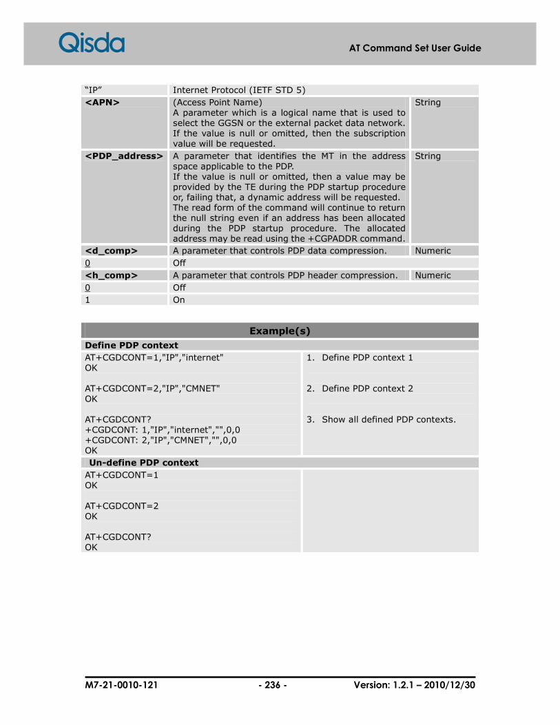
M7-21-0010-121 - 236 - Version: 1.2.1 – 2010/12/30
AT Command Set User Guide
“IP” Internet Protocol (IETF STD 5)
<APN> (Access Point Name) A parameter which is a logical name that is used to select the GGSN or the external packet data network. If the value is null or omitted, then the subscription value will be requested.
String
<PDP_address> A parameter that identifies the MT in the address space applicable to the PDP. If the value is null or omitted, then a value may be provided by the TE during the PDP startup procedure or, failing that, a dynamic address will be requested. The read form of the command will continue to return the null string even if an address has been allocated during the PDP startup procedure. The allocated address may be read using the +CGPADDR command.
String
<d_comp> A parameter that controls PDP data compression. Numeric
0 Off
<h_comp> A parameter that controls PDP header compression. Numeric
0 Off
1 On
Example(s)
Define PDP context
AT+CGDCONT=1,"IP","internet" OK AT+CGDCONT=2,"IP","CMNET" OK AT+CGDCONT? +CGDCONT: 1,"IP","internet","",0,0 +CGDCONT: 2,"IP","CMNET","",0,0 OK
1. Define PDP context 1 2. Define PDP context 2 3. Show all defined PDP contexts.
Un-define PDP context
AT+CGDCONT=1 OK AT+CGDCONT=2 OK AT+CGDCONT? OK
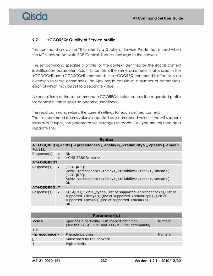
M7-21-0010-121 - 237 - Version: 1.2.1 – 2010/12/30
AT Command Set User Guide
9.2 +CGQREQ: Quality of Service profile
This command allows the TE to specify a Quality of Service Profile that is used when
the MT sends an Activate PDP Context Request message to the network.
The set command specifies a profile for the context identified by the (local) context
identification parameter, <cid>. Since this is the same parameter that is used in the
+CGDCONT and +CGDSCONT commands, the +CGQREQ command is effectively an
extension to these commands. The QoS profile consists of a number of parameters,
each of which may be set to a separate value.
A special form of the set command, +CGQREQ= <cid> causes the requested profile
for context number <cid> to become undefined.
The read command returns the current settings for each defined context.
The test command returns values supported as a compound value. If the MT supports
several PDP types, the parameter value ranges for each PDP type are returned on a
separate line.
Syntax
AT+CGQREQ=[<cid>[,<precedence>[,<delay>[,<reliability>[,<peak>[,<mean>]]]]]]
Response(s) � OK � +CME ERROR: <err>
AT+CGQREQ?
Response(s) � [+CGQREQ: <cid>,<precedence>,<delay>,<reliability>,<peak>,<mean>] [+CGQREQ: <cid>,<precedence>,<delay>,<reliability>,<peak>,<mean>] OK
AT+CGQREQ=?
Response(s) � +CGQREQ: <PDP_type>,(list of supported <precedence>s),(list of supported <delay>s),(list of supported <reliability>s),(list of supported <peak>s),(list of supported <mean>s) OK
Parameter(s)
<cid> Specifies a particular PDP context definition. (see the +CGDCONT and +CGDSCONT commands)
Numeric
1-2
<precedence> Precedence class Numeric
0 Subscribed by the network
1 High priority

M7-21-0010-121 - 238 - Version: 1.2.1 – 2010/12/30
AT Command Set User Guide
2 Normal priority
3 Low priority
<delay> Delay class Numeric
0 Subscribed by the network
1-4 SDU size: 128 octets SDU size: 1024 octets
Mean Transfer Delay
95 percentile Mean Transfer Delay
95 percentile
1 <0.5 <1.5 <2 <7
2 <5 <25 <15 <75
3 <50 <250 <75 <375
4 unspecified
<reliability> Reliability class Numeric
0 Subscribed by the network
1 Non real-time traffic, error-sensitive application that cannot cope with data loss.
2 Non real-time traffic, error-sensitive application that can cope with infrequent data loss.
3 Non real-time traffic, error-sensitive application that can cope with data loss, GMM/SM, and SMS.
4 Real-time traffic, error-sensitive application that can cope with data loss.
5 Real-time traffic, error non-sensitive application that can cope with data loss.
<peak> Peak throughput class Numeric
0 Subscribed by the network
1 Up to 1000 (8 kbit/s)
2 Up to 2000 (16 kbit/s)
3 Up to 4000 (32 kbit/s)
4 Up to 8000 (64 kbit/s)
5 Up to 16000 (128 kbit/s)
6 Up to 32000 (256 kbit/s)
7 Up to 64000 (512 kbit/s)
8 Up to 128000 (1024 kbit/s)
9 Up to 256000 (2048 kbit/s)
< mean > Mean throughput class Numeric
0 Subscribed by the network
1 100 (~0.22 bit/s)
2 200 (~0.44 bit/s)
3 500 (~1.11 bit/s)
4 1000 (~2.2 bit/s)
5 2000 (~4.4 bit/s)
6 5000 (~11.1 bit/s)
7 10000 (~22 bit/s)
8 20000 (~44 bit/s)
9 50000 (~111 bit/s)
10 100000 (~0.22 kbit/s)
11 200000 (~0.44 kbit/s)

M7-21-0010-121 - 239 - Version: 1.2.1 – 2010/12/30
AT Command Set User Guide
12 500000 (~1.11 kbit/s)
13 1000000 (~2.2 kbit/s)
14 2000000 (~4.4 kbit/s)
15 5000000 (~11.1 kbit/s)
16 10000000 (~22 kbit/s)
17 20000000 (~44 kbit/s)
18 50000000 (~111 kbit/s)
31 Best effort
<PDP_type> Packet Data Protocol type String
“IP” Internet Protocol (IETF STD 5)

M7-21-0010-121 - 240 - Version: 1.2.1 – 2010/12/30
AT Command Set User Guide
9.3 +CGQMIN: Quality of Service profile (minimum acceptable)
This command allows the TE to specify a minimum acceptable profile which is
checked by the MT against the negotiated profile returned in the Activate PDP
Context Accept message.
The set command specifies a profile for the context identified by the (local) context
identification parameter, <cid>. Since this is the same parameter that is used in the
+CGDCONT and +CGDSCONT commands, the +CGQMIN command is effectively an
extension to these commands. The QoS profile consists of a number of parameters,
each of which may be set to a separate value.
A special form of the set command, +CGQMIN= <cid> causes the minimum
acceptable profile for context number <cid> to become undefined. In this case, no
check is made against the negotiated profile.
The read command returns the current settings for each defined context.
The test command returns values supported as a compound value. If the MT supports
several PDP types, the parameter value ranges for each PDP type are returned on a
separate line.
Syntax
AT+CGQMIN=[<cid>[,<precedence>[,<delay>[,<reliability>[,<peak>[,<mean>]]]]]]
Response(s) � OK � +CME ERROR: <err>
AT+CGQMIN?
Response(s) � [+CGQMIN: <cid>,<precedence>,<delay>,<reliability>,<peak>,<mean>] [+CGQMIN: <cid>,<precedence>,<delay>,<reliability>,<peak>,<mean>] OK
AT+CGQMIN=?
Response(s) � + CGQMIN: <PDP_type>,(list of supported <precedence>s),(list of supported <delay>s),(list of supported <reliability>s),(list of supported <peak>s),(list of supported <mean>s) OK

M7-21-0010-121 - 241 - Version: 1.2.1 – 2010/12/30
AT Command Set User Guide
Parameter(s)
<cid> Specifies a particular PDP context definition. (see the +CGDCONT and +CGDSCONT commands)
Numeric
1-2
<precedence> Precedence class Numeric
0 Subscribed by the network
1 High priority
2 Normal priority
3 Low priority
<delay> Delay class Numeric
0 Subscribed by the network
1-4 SDU size: 128 octets SDU size: 1024 octets
Mean Transfer Delay
95 percentile Mean Transfer Delay
95 percentile
1 <0.5 <1.5 <2 <7
2 <5 <25 <15 <75
3 <50 <250 <75 <375
4 unspecified
<reliability> Reliability class Numeric
0 Subscribed by the network
1 Non real-time traffic, error-sensitive application that cannot cope with data loss.
2 Non real-time traffic, error-sensitive application that can cope with infrequent data loss.
3 Non real-time traffic, error-sensitive application that can cope with data loss, GMM/SM, and SMS.
4 Real-time traffic, error-sensitive application that can cope with data loss.
5 Real-time traffic, error non-sensitive application that can cope with data loss.
<peak> Peak throughput class Numeric
0 Subscribed by the network
1 Up to 1000 (8 kbit/s)
2 Up to 2000 (16 kbit/s)
3 Up to 4000 (32 kbit/s)
4 Up to 8000 (64 kbit/s)
5 Up to 16000 (128 kbit/s)
6 Up to 32000 (256 kbit/s)
7 Up to 64000 (512 kbit/s)
8 Up to 128000 (1024 kbit/s)
9 Up to 256000 (2048 kbit/s)
< mean > Mean throughput class Numeric
0 Subscribed by the network
1 100 (~0.22 bit/s)
2 200 (~0.44 bit/s)
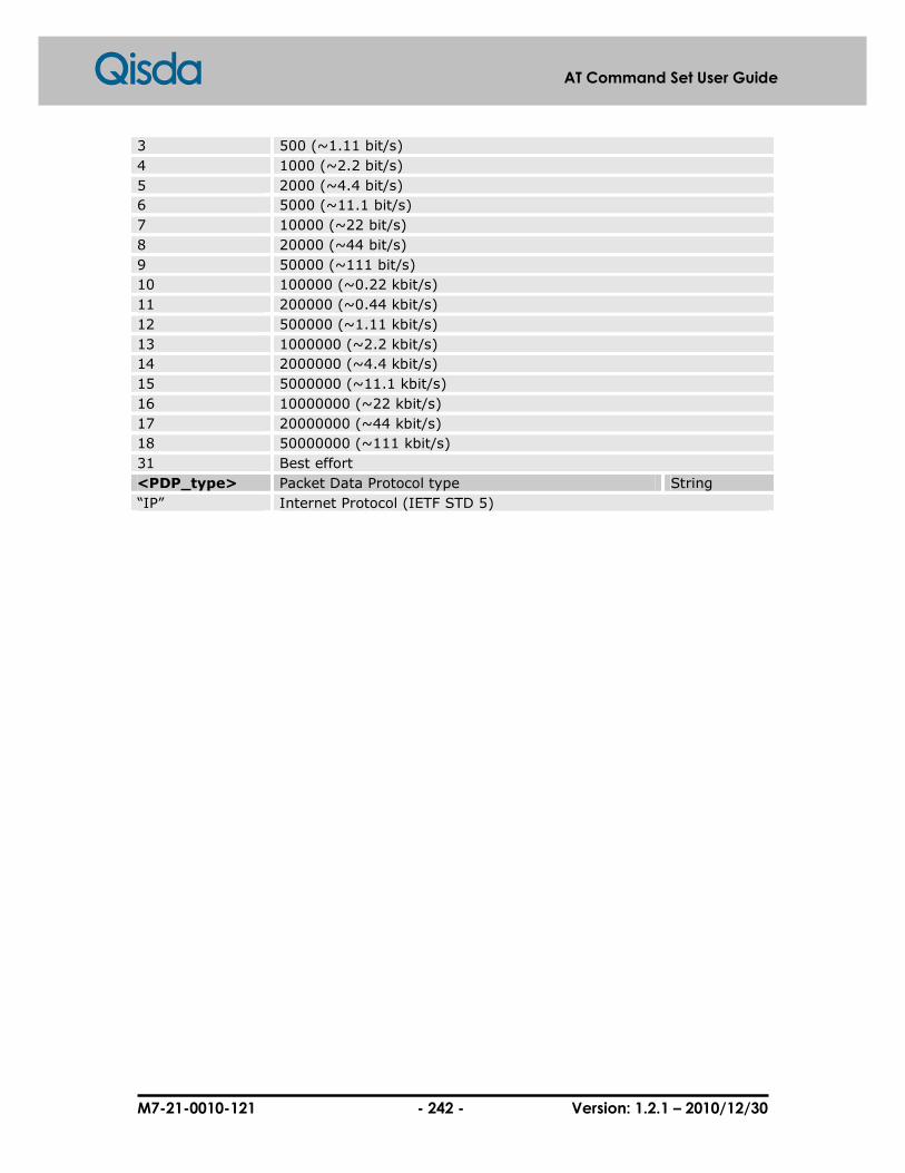
M7-21-0010-121 - 242 - Version: 1.2.1 – 2010/12/30
AT Command Set User Guide
3 500 (~1.11 bit/s)
4 1000 (~2.2 bit/s)
5 2000 (~4.4 bit/s)
6 5000 (~11.1 bit/s)
7 10000 (~22 bit/s)
8 20000 (~44 bit/s)
9 50000 (~111 bit/s)
10 100000 (~0.22 kbit/s)
11 200000 (~0.44 kbit/s)
12 500000 (~1.11 kbit/s)
13 1000000 (~2.2 kbit/s)
14 2000000 (~4.4 kbit/s)
15 5000000 (~11.1 kbit/s)
16 10000000 (~22 kbit/s)
17 20000000 (~44 kbit/s)
18 50000000 (~111 kbit/s)
31 Best effort
<PDP_type> Packet Data Protocol type String
“IP” Internet Protocol (IETF STD 5)
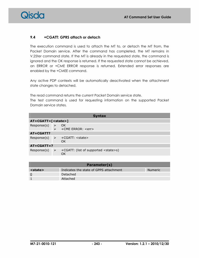
M7-21-0010-121 - 243 - Version: 1.2.1 – 2010/12/30
AT Command Set User Guide
9.4 +CGATT: GPRS attach or detach
The execution command is used to attach the MT to, or detach the MT from, the
Packet Domain service. After the command has completed, the MT remains in
V.25ter command state. If the MT is already in the requested state, the command is
ignored and the OK response is returned. If the requested state cannot be achieved,
an ERROR or +CME ERROR response is returned. Extended error responses are
enabled by the +CMEE command.
Any active PDP contexts will be automatically deactivated when the attachment
state changes to detached.
The read command returns the current Packet Domain service state.
The test command is used for requesting information on the supported Packet
Domain service states.
Syntax
AT+CGATT=[<state>]
Response(s) � OK � +CME ERROR: <err>
AT+CGATT?
Response(s) � +CGATT: <state> OK
AT+CGATT=?
Response(s) � +CGATT: (list of supported <state>s) OK
Parameter(s)
<state> Indicates the state of GPPS attachment Numeric
0 Detached
1 Attached
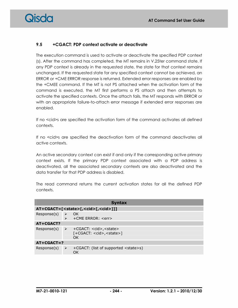
M7-21-0010-121 - 244 - Version: 1.2.1 – 2010/12/30
AT Command Set User Guide
9.5 +CGACT: PDP context activate or deactivate
The execution command is used to activate or deactivate the specified PDP context
(s). After the command has completed, the MT remains in V.25ter command state. If
any PDP context is already in the requested state, the state for that context remains
unchanged. If the requested state for any specified context cannot be achieved, an
ERROR or +CME ERROR response is returned. Extended error responses are enabled by
the +CMEE command. If the MT is not PS attached when the activation form of the
command is executed, the MT first performs a PS attach and then attempts to
activate the specified contexts. Once the attach fails, the MT responds with ERROR or
with an appropriate failure-to-attach error message if extended error responses are
enabled.
If no <cid>s are specified the activation form of the command activates all defined
contexts.
If no <cid>s are specified the deactivation form of the command deactivates all
active contexts.
An active secondary context can exist if and only if the corresponding active primary
context exists. If the primary PDP context associated with a PDP address is
deactivated, all the associated secondary contexts are also deactivated and the
data transfer for that PDP address is disabled.
The read command returns the current activation states for all the defined PDP
contexts.
Syntax
AT+CGACT=[<state>[,<cid>[,<cid>]]]
Response(s) � OK � +CME ERROR: <err>
AT+CGACT?
Response(s) � +CGACT: <cid>,<state> [+CGACT: <cid>,<state>] OK
AT+CGACT=?
Response(s) � +CGACT: (list of supported <state>s) OK
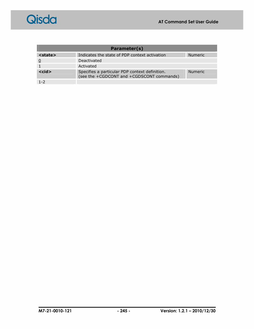
M7-21-0010-121 - 245 - Version: 1.2.1 – 2010/12/30
AT Command Set User Guide
Parameter(s)
<state> Indicates the state of PDP context activation Numeric
0 Deactivated
1 Activated
<cid> Specifies a particular PDP context definition. (see the +CGDCONT and +CGDSCONT commands)
Numeric
1-2

M7-21-0010-121 - 246 - Version: 1.2.1 – 2010/12/30
AT Command Set User Guide
9.6 +CGDATA: Enter data state
The execution command causes the MT to perform whatever actions are necessary
to establish communication between the TE and the network using one or more GPRS
PDP types. This may include performing a GPRS attach and one or more PDP context
activations.
If the <cid> value is not defined to the MT, the MT will return an ERROR or +CME ERROR
response. Otherwise, the MT issues the intermediate result code CONNECT and enters
V.25ter online data state.
GPRS attachment and PDP context activation procedures may take place prior to or
during the PDP startup if they have not already been performed using the +CGATT
and +CGACT commands.
If context activation takes place during the PDP startup, one or more <cid>s may be
specified in order to provide the information needed for the context activation
request(s). During each PDP startup procedure the MT may have access to some or
all of the following information -
� The MT may have a priori knowledge, for example, it may implement only one
PDP type.
� The TE may provide a PDP type and/or PDP address to the MT during in the PDP
startup procedure.
If any of this information is in conflict, the command will fail.
Any PDP type and/or PDP address present in the above information shall be
compared with the PDP type and/or PDP address in any context definitions specified
in the command in the order in which their <cid>s appear. For a context definition to
match -
� The PDP type must match exactly.
� The PDP addresses are considered to match if they are identical or if either or
both addresses are unspecified. For example, a PPP NCP request specifying PDP
type = IP and no PDP address would cause the MT to search through the
specified context definitions for one with PDP type = IP and any PDP address.
The context shall be activated using the matched value for PDP type and a static
PDP address if available, together with the other information found in the PDP context
definition. If a static PDP address is not available then a dynamic address is
requested.
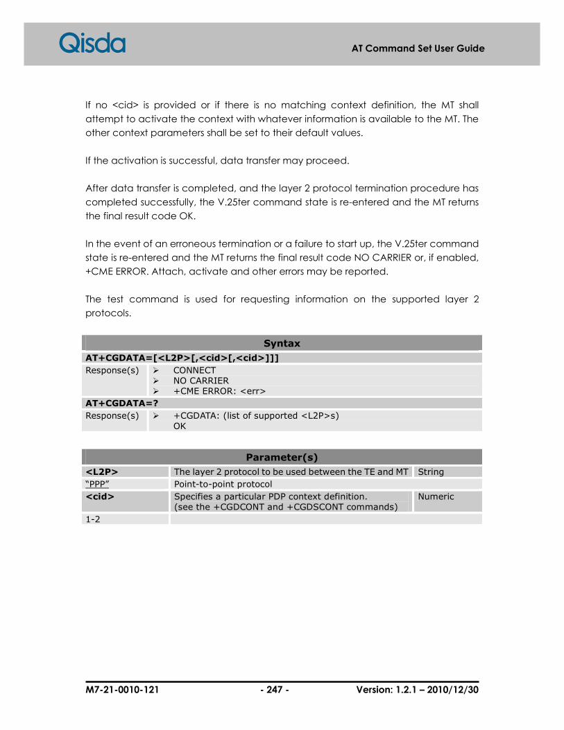
M7-21-0010-121 - 247 - Version: 1.2.1 – 2010/12/30
AT Command Set User Guide
If no <cid> is provided or if there is no matching context definition, the MT shall
attempt to activate the context with whatever information is available to the MT. The
other context parameters shall be set to their default values.
If the activation is successful, data transfer may proceed.
After data transfer is completed, and the layer 2 protocol termination procedure has
completed successfully, the V.25ter command state is re-entered and the MT returns
the final result code OK.
In the event of an erroneous termination or a failure to start up, the V.25ter command
state is re-entered and the MT returns the final result code NO CARRIER or, if enabled,
+CME ERROR. Attach, activate and other errors may be reported.
The test command is used for requesting information on the supported layer 2
protocols.
Syntax
AT+CGDATA=[<L2P>[,<cid>[,<cid>]]]
Response(s) � CONNECT � NO CARRIER � +CME ERROR: <err>
AT+CGDATA=?
Response(s) � +CGDATA: (list of supported <L2P>s) OK
Parameter(s)
<L2P> The layer 2 protocol to be used between the TE and MT String
“PPP” Point-to-point protocol
<cid> Specifies a particular PDP context definition. (see the +CGDCONT and +CGDSCONT commands)
Numeric
1-2

M7-21-0010-121 - 248 - Version: 1.2.1 – 2010/12/30
AT Command Set User Guide
9.7 +CGPADDR: Show PDP address
The execution command returns a list of PDP addresses for the specified context
identifiers.
Syntax
AT+CGPADDR=[<cid>[,<cid>]]
Response(s) � +CGPADDR: <cid>,<PDP_address> [+CGPADDR: <cid>,<PDP_address>] OK
� +CME ERROR: <err>
AT+CGPADDR=?
Response(s) � +CGPADDR: (list of defined <cid>s) OK
Parameter(s)
<cid> Specifies a particular PDP context definition. (see the +CGDCONT and +CGDSCONT commands) If no <cid> is specified, the addresses for all defined contexts are returned.
Numeric
1-2
<PDP_address> A string that identifies the MT in the address space applicable to the PDP. The address may be static or dynamic. For a static address, it will be the one set by the +CGDCONT and +CGDSCONT commands when the context was defined. For a dynamic address it will be the one assigned during the last PDP context activation that used the context definition referred to by <cid>. <PDP_address> is omitted if none is available.
String
Example(s)
AT+CGDCONT=1,"IP","internet" OK AT+CGPADDR=? +CGPADDR: (1) OK AT+CGACT=1 OK AT+CGPADDR=1 +CGPADDR: 1,"010.194.009.097" OK AT+CGDCONT=2,"IP","NET2"
1. Define PDP context 2. List defined <cid> 3. Activate PDP context 4. Show PDP address 5. Define PDP context 2

M7-21-0010-121 - 249 - Version: 1.2.1 – 2010/12/30
AT Command Set User Guide
OK AT+CGPADDR=? +CGPADDR: (1,2) OK
6. List all defined <cid>s

M7-21-0010-121 - 250 - Version: 1.2.1 – 2010/12/30
AT Command Set User Guide
9.8 +CGAUTO: Automatic response to a network request for PDP context
activation
The set command disables or enables an automatic positive response (auto-answer)
to the receipt of a Request PDP Context Activation message from the network. It also
provides control over the use of the V.25ter basic commands 'S0', 'A and 'H' for
handling network requests for PDP context activation. The setting does not affect the
issuing of the unsolicited result code RING or +CRING.
The test command returns the values of <n> supported by the MT as a compound
value.
When the +CGAUTO=0 command is received, the MT shall not perform a PS detach if
it is attached. Subsequently, when the MT announces a network request for PDP
context activation by issuing the unsolicited result code RING or +CRING, the TE may
manually accept or reject the request by issuing the +CGANS command or may
simply ignore the network request.
When the +CGAUTO=1 command is received, the MT shall attempt to perform a PS
attach if it is not already attached. Failure will result in ERROR or, if enabled, +CME
ERROR being returned to the TE. Subsequently, when the MT announces a network
request for PDP context activation by issuing the unsolicited result code RING or
+CRING to the TE, this is followed by the intermediate result code CONNECT. The MT
then enters V.25ter online data state and follows the same procedure as it would
after having received a +CGANS=1 with no <L2P> or <cid> values specified.
Syntax
AT+CGAUTO=[<n>]
Response(s) � OK � +CME ERROR: <err>
AT+CGAUTO?
Response(s) � +CGAUTO: <n> OK
AT+CGAUTO=?
Response(s) � +CGAUTO: (list of supported <n>s) OK
Parameter(s)
<n> Numeric
0 Turn off automatic response for Packet Domain only.
1 Turn on automatic response for Packet Domain only.

M7-21-0010-121 - 251 - Version: 1.2.1 – 2010/12/30
AT Command Set User Guide
2 Modem compatibility mode, Packet Domain only.
3 Modem compatibility mode, Packet Domain and circuit switched calls.
For <n> = 0 Packet Domain network requests are manually accepted or rejected by the +CGANS command. For <n> = 1 Packet Domain network requests are automatically accepted according to the description above. For <n> = 2, automatic acceptance of Packet Domain network requests is controlled by the 'S0' command. Manual control uses the 'A' and 'H' commands, respectively, to accept and reject Packet Domain requests. (+CGANS may also be used.) Incoming circuit switched calls can be neither manually nor automatically answered. For <n> = 3, automatic acceptance of both Packet Domain network requests and incoming circuit switched calls is controlled by the 'S0' command. Manual control uses the 'A' and 'H' commands, respectively, to accept and reject Packet Domain requests. (+CGANS may also be used.) Circuit switched calls are handled as described elsewhere in this specification.

M7-21-0010-121 - 252 - Version: 1.2.1 – 2010/12/30
AT Command Set User Guide
9.9 +CGANS: Manual response to a network request for PDP context
activation
The execution command requests the MT to respond to a network request for Packet
Domain PDP context activation which has been signaled to the TE by the RING or
+CRING: unsolicited result code. The <response> parameter allows the TE to accept
or reject the request.
If <response> is 0, the request is rejected and the MT returns OK to the TE.
If <response> is 1, the following procedure is followed by the MT.
Commands follows the +CGANS command in the AT command line shall not be
processed by the MT.
If the <L2P> parameter value is unacceptable to the MT, the MT shall return an ERROR
or +CME ERROR response. Otherwise, the MT issues the intermediate result code
CONNECT and enters V.25ter online data state.
The detailed behavior after the online data state has been entered is dependent on
the PDP type. It is described briefly in 3GPP TS 27.060[34], and more detail is provided
in 3GPP TS 29.061[39] and the specifications for the relevant PDPs. PDP context
activation procedures shall take place prior to or during the PDP startup.
One or more <cid>s may be specified in order to provide the values needed for the
context activation request.
During the PDP startup procedure the MT has the PDP type and the PDP address
provided by the network in the Request PDP Context Activation message. The MT
may also have some or all of the following information -
The MT may have a priori knowledge, for example, it may implement only one PDP
type.
Maybe the command has provided an <L2P> parameter value already.
The TE may provide one or both of PDP type and PDP address to the MT in the PDP
startup.
If any of this information is in conflict, the command will fail.
If one or more <cid> is provided, an attempt shall be made to identify an appropriate
context definition by matching the PDP type and PDP address in the network request
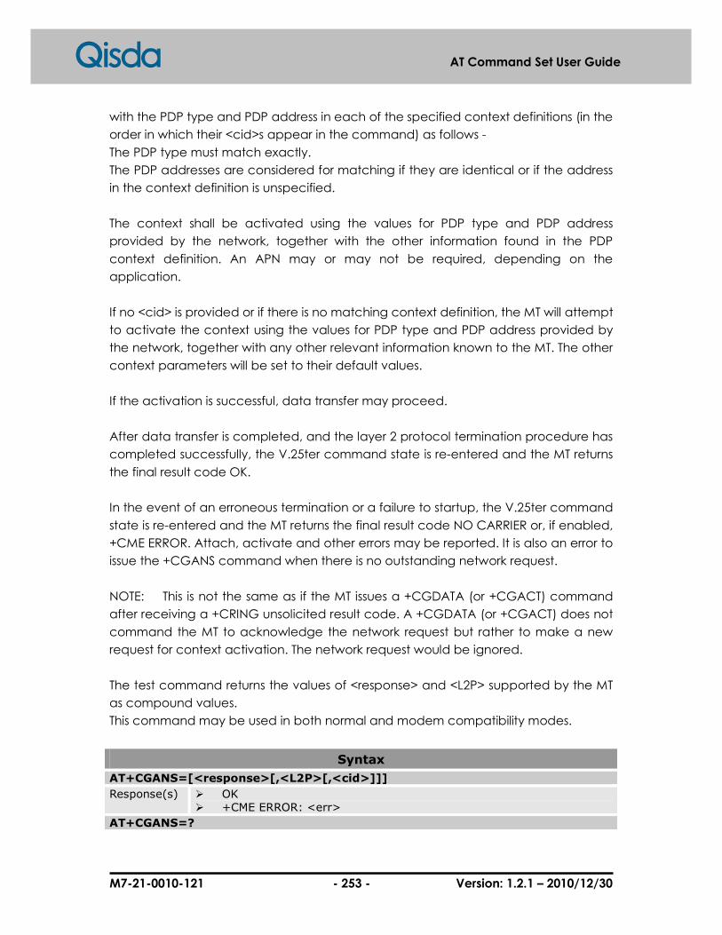
M7-21-0010-121 - 253 - Version: 1.2.1 – 2010/12/30
AT Command Set User Guide
with the PDP type and PDP address in each of the specified context definitions (in the
order in which their <cid>s appear in the command) as follows -
The PDP type must match exactly.
The PDP addresses are considered for matching if they are identical or if the address
in the context definition is unspecified.
The context shall be activated using the values for PDP type and PDP address
provided by the network, together with the other information found in the PDP
context definition. An APN may or may not be required, depending on the
application.
If no <cid> is provided or if there is no matching context definition, the MT will attempt
to activate the context using the values for PDP type and PDP address provided by
the network, together with any other relevant information known to the MT. The other
context parameters will be set to their default values.
If the activation is successful, data transfer may proceed.
After data transfer is completed, and the layer 2 protocol termination procedure has
completed successfully, the V.25ter command state is re-entered and the MT returns
the final result code OK.
In the event of an erroneous termination or a failure to startup, the V.25ter command
state is re-entered and the MT returns the final result code NO CARRIER or, if enabled,
+CME ERROR. Attach, activate and other errors may be reported. It is also an error to
issue the +CGANS command when there is no outstanding network request.
NOTE: This is not the same as if the MT issues a +CGDATA (or +CGACT) command
after receiving a +CRING unsolicited result code. A +CGDATA (or +CGACT) does not
command the MT to acknowledge the network request but rather to make a new
request for context activation. The network request would be ignored.
The test command returns the values of <response> and <L2P> supported by the MT
as compound values.
This command may be used in both normal and modem compatibility modes.
Syntax
AT+CGANS=[<response>[,<L2P>[,<cid>]]]
Response(s) � OK � +CME ERROR: <err>
AT+CGANS=?

M7-21-0010-121 - 254 - Version: 1.2.1 – 2010/12/30
AT Command Set User Guide
Response(s) � +CGANS: (list of supported <response>s),(list of supported <L2P>s) OK
Parameter(s)
<response> Specifies how the request should be responded to. Numeric
0 Reject the request.
1 Accept and request that the PDP context be activated.
<L2P> Indicates the layer 2 protocol to be used (see +CGDATA command).
String
“PPP” Point-to-point protocol
<cid> Specifies a particular PDP context definition. (see the +CGDCONT and +CGDSCONT commands)
Numeric

M7-21-0010-121 - 255 - Version: 1.2.1 – 2010/12/30
AT Command Set User Guide
9.10 + CGCLASS: GPRS mobile station class
The set command is used to set the MT for operating base on the specified GPRS
mobile class. If the requested class is not supported, an ERROR or +CME ERROR
response is returned. Extended error responses are enabled by the +CMEE command.
The read command returns the current GPRS mobile class.
The test command is used for requesting information on the supported GPRS mobile
classes.
Syntax
AT+CGCLASS= [<class>]
Response(s) � OK � +CME ERROR: <err>
AT+CGCLASS?
Response(s) � +CGCLASS: <class> OK
AT+CGCLASS=?
Response(s) � +CGCLASS: (list of supported <class>s) OK
Parameter(s)
<class> The GPRS mobile class. If the MT is GPRS attached when the set command is issued with a <class> = CC specified, a detach request shall be sent to the network.
String
“B” class B
“CG” class C in GPRS only mode
“CC” class C in circuit switched only mode

M7-21-0010-121 - 256 - Version: 1.2.1 – 2010/12/30
AT Command Set User Guide
9.11 + CGEREP: GPRS event reporting
Set command enables or disables to send unsolicited result codes, +CGEV: XXX, from
MT to TE in the case of certain events occurring in the Packet Domain MT or the
network. <mode> controls the processing of unsolicited result codes specified within
this command. <bfr> controls the effect on buffered codes when <mode> 1 or 2 is
entered. If a setting is not supported by the MT, ERROR or +CME ERROR: is returned.
Read command returns the current mode and buffer settings.
Test command returns the modes and buffer settings supported by the MT as
compound values.
Syntax
AT+CGEREP=[<mode>[,<bfr>]]
Response(s) � OK � +CME ERROR: <err>
AT+CGEREP?
Response(s) � +CGEREP: <mode>,<bfr> OK
AT+CGEREP=?
Response(s) � +CGEREP: (list of supported <mode>s),(list of supported <bfr>s) OK
Parameter(s)
<mode> Numeric
0 Buffer unsolicited result codes in the MT; if MT result code buffer is full, the oldest ones can be discarded. No codes are forwarded to the TE.
1 Discard unsolicited result codes when MT-TE link is reserved (e.g. in on-line data mode); otherwise forward them directly to the TE.
2 Buffer unsolicited result codes in the MT when MT-TE link is reserved (e.g. in on-line data mode) and flush them to the TE when MT-TE link becomes available; otherwise forward them directly to the TE
<bfr> Numeric
0 MT buffer of unsolicited result codes defined within this command is cleared when <mode> 1 or 2 is entered.
1 MT buffer of unsolicited result codes defined within this command is flushed to the TE when <mode> 1 or 2 is entered (OK response shall be given before flushing the codes).

M7-21-0010-121 - 257 - Version: 1.2.1 – 2010/12/30
AT Command Set User Guide
Defined Events (URCs)
+CGEV: REJECT <PDP_type>,<PDP_addr>
A network request for PDP context activation occurred when the MT was unable to report it to the TE with a +CRING unsolicited result code and was automatically rejected.
+CGEV: NW REACT <PDP_type>,<PDP_addr>,[<cid>]
The network has requested a context reactivation. The <cid> that was used to reactivate the context is provided if known to the MT.
+CGEV: NW DEACT <PDP_type>,<PDP_addr>,[<cid>]
The network has forced a context deactivation. The <cid> that was used to activate the context is provided if known to the MT.
+CGEV: ME DEACT <PDP_type>,<PDP_addr>,[<cid>]
The mobile equipment has forced a context deactivation. The <cid> that was used to activate the context is provided if known to the MT.
+CGEV: NW DETACH
The network has forced a PS detach. This implies that all active contexts have been deactivated. These are not reported separately.
+CGEV: ME DETACH
The mobile equipment has forced a PS detach. This implies that all active contexts have been deactivated. These are not reported separately.
+CGEV: NW CLASS <class>
The network has forced a change of MS class. The highest available class is reported (see +CGCLASS).
+CGEV: ME CLASS <class>
The mobile equipment has forced a change of MS class. The highest available class is reported (see +CGCLASS).

M7-21-0010-121 - 258 - Version: 1.2.1 – 2010/12/30
AT Command Set User Guide
9.12 + CGREG: GPRS network registration status
The set command controls the presentation of an unsolicited result code +CGREG:
<stat> when <n>=1 and there is a change in the MT's GPRS network registration status,
or controls code +CGREG: <stat>[,<lac>,<ci>] when <n>=2 and there is a change of
the network cell.
NOTE: If the GPRS MT also supports circuit mode services, the +CREG command and
+CREG: result code will apply to the registration status and location information for
those services.
The read command returns the status of result code presentation and an integer
<stat> which shows whether the network has currently indicated the registration of
the MT. Location information elements <lac> and <ci> are returned only when <n>=2
and MT is registered in the network.
Syntax
AT+CGREG=[<n>]
Response(s) � OK � +CME ERROR: <err>
AT+CGREG?
Response(s) � +CGREG: <n>,<stat>[,<lac>,<ci>] OK
AT+CGREG=?
Response(s) � +CGREG: (list of supported <n>s) OK
Unsolicited Result Codes
When <n>=1 and there is a change in the MT's GPRS network registration status. � +CGREG: <stat> When <n>=2 and there is a change of the network cell. � +CGREG: <stat>,<lac>,<ci>
Parameter(s)
<n> Numeric
0 Disable network registration unsolicited result code.
1 Enable network registration unsolicited result code. +CGREG: <stat>
2 Enable network registration and location information unsolicited result code. +CGREG: <stat>[,<lac>,<ci>]
<stat> Numeric
0 Not registered, ME is not currently searching an operator to register to.
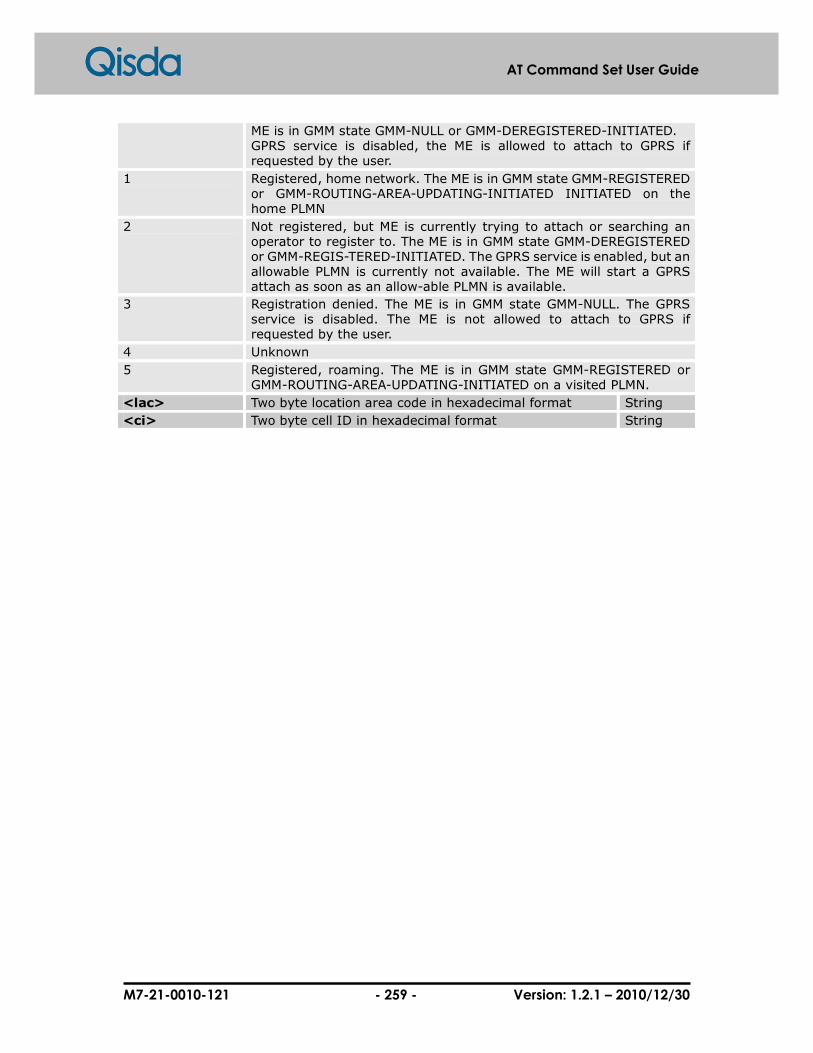
M7-21-0010-121 - 259 - Version: 1.2.1 – 2010/12/30
AT Command Set User Guide
ME is in GMM state GMM-NULL or GMM-DEREGISTERED-INITIATED. GPRS service is disabled, the ME is allowed to attach to GPRS if requested by the user.
1 Registered, home network. The ME is in GMM state GMM-REGISTERED or GMM-ROUTING-AREA-UPDATING-INITIATED INITIATED on the home PLMN
2 Not registered, but ME is currently trying to attach or searching an operator to register to. The ME is in GMM state GMM-DEREGISTERED or GMM-REGIS-TERED-INITIATED. The GPRS service is enabled, but an allowable PLMN is currently not available. The ME will start a GPRS attach as soon as an allow-able PLMN is available.
3 Registration denied. The ME is in GMM state GMM-NULL. The GPRS service is disabled. The ME is not allowed to attach to GPRS if requested by the user.
4 Unknown
5 Registered, roaming. The ME is in GMM state GMM-REGISTERED or GMM-ROUTING-AREA-UPDATING-INITIATED on a visited PLMN.
<lac> Two byte location area code in hexadecimal format String
<ci> Two byte cell ID in hexadecimal format String

M7-21-0010-121 - 260 - Version: 1.2.1 – 2010/12/30
AT Command Set User Guide
9.13 + CGSMS: Select service for MO SMS messages
The set command is used to specify the service or service preference that the MT will
use to send MO SMS messages.
The read command returns the currently selected service or service preference.
The test command is used for requesting information on the currently available
services and service preferences.
Syntax
AT+CGSMS=[<service>]
Response(s) � OK � +CME ERROR: <err>
AT+CGSMS?
Response(s) � +CGSMS: <service> OK
AT+CGSMS=?
Response(s) � +CGSMS: (list of currently available <service>s) OK
Parameter(s)
<service> Indicates the service or service preference to be used. Numeric
0 Packet Domain
1 Circuit switched
2 Packet Domain preferred (use circuit switched if GPRS not available)
3 circuit switched preferred (use Packet Domain if circuit switched not available)

M7-21-0010-121 - 261 - Version: 1.2.1 – 2010/12/30
AT Command Set User Guide
9.14 D: Request GPRS service
This command causes the MT to perform any action that is necessary to establish
communication between the TE and external PDN.
The V.25ter’D’(Dial) command causes the MT to enter the V.25ter online data state
and, with the TE, to start the specified layer2 protocol. The MT shall return CONNECT to
confirm acceptance of the command prior to enter the V.25ter online data state. No
further commands may follow on the AT command line.
The detailed behavior after the online data state has been entered is dependent on
the PDP type. It is described briefly in clauses 8 (for X.25) and 9 (for IP) of GSM 07.06.
GPRS attachment and PDP context activation procedures may take place prior to or
during the PDP startup if they have not already been performed using the +CGATT
and +CGACT commands.
When the layer 2 protocol has terminated, either as a result of sequentially shut down
of the PDP or an error, the MT shall enter V.25ter command state and return the NO
CARRIER final result code.
If <called_address> is supported and provided, the MT shall automatically set up a
virtual call to the specified address after the PDP context has been activated.
If <L2P> and <cid> are supported, their usage shall be the same as in the +CGDATA
command. Commands such as +CGDCONT, +CGQREQ, etc. may then be used in
the modem initialization AT command string to set values for PDP type, APN, QoS etc.
If <L2P> is not supported or is supported but omitted, the MT shall use a layer 2
protocol appropriate to the PDP type.
If <cid> is not supported or is supported but omitted, the MT shall attempt to activate
the context using:
any information provided by the TE during the PDP startup procedure, e.g. the TE may
provide a PDP type and/or PDP address to the MT,
or (b) a prior knowledge, e.g. the MT may implement only one PDP type,
or (c) using the ‘Empty PDP type’ (GSM 04.08). (No PDP address or APN shall be sent in
this case and only one PDP context subscription record shall be present in the HLR for
this subscriber.)
This command may be used in both normal and modem compatibility modes.

M7-21-0010-121 - 262 - Version: 1.2.1 – 2010/12/30
AT Command Set User Guide
Syntax
ATD*<GPRS_SC>[*[<called_address>][*[<L2P>][*[<cid>]]]]#
Response(s) � CONNECT � NO CARRIER
Parameter(s)
<GPRS_SC> (GPRS Service Code) a digit string which identifies a request to use the GPRS
Numeric
99 GPRS modem service
<called_address> A string that identifies the called party in the address space applicable to the PDP. For communications software that does not support arbitrary characters in the dial string, a numeric equivalent may be used. Also, the character comma’,’. May be used as a substitute for the character period’.’. [<host>][@[<port>][@[<protocol>]]] where <host>, <port> and <protocol> are defined in the +CGDCONT description. For communications software that does not support arbitrary characters in the dial string, a numeric equivalent may be used. However, this should be avoided if at all possible.
String
<L2P> A string which indicates the layer 2 protocol to be used. For communications software that does not support arbitrary characters in the dial string, a numeric equivalent shall be used: 0 NULL 1 PPP 2 PAD 3 X25 9yyyy M-xxxx
String
“PPP” Point-to-point protocol
<cid> Specifies a particular PDP context definition. (see the +CGDCONT and +CGDSCONT commands)
Numeric
1-2
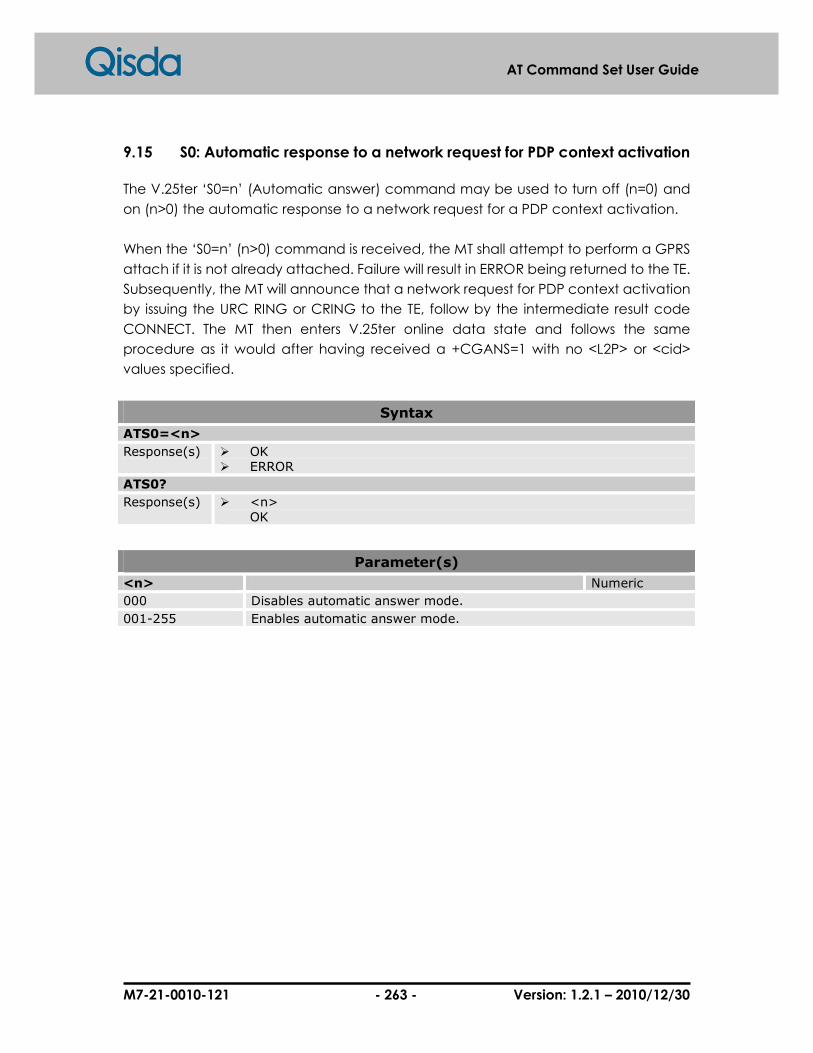
M7-21-0010-121 - 263 - Version: 1.2.1 – 2010/12/30
AT Command Set User Guide
9.15 S0: Automatic response to a network request for PDP context activation
The V.25ter ‘S0=n’ (Automatic answer) command may be used to turn off (n=0) and
on (n>0) the automatic response to a network request for a PDP context activation.
When the ‘S0=n’ (n>0) command is received, the MT shall attempt to perform a GPRS
attach if it is not already attached. Failure will result in ERROR being returned to the TE.
Subsequently, the MT will announce that a network request for PDP context activation
by issuing the URC RING or CRING to the TE, follow by the intermediate result code
CONNECT. The MT then enters V.25ter online data state and follows the same
procedure as it would after having received a +CGANS=1 with no <L2P> or <cid>
values specified.
Syntax
ATS0=<n>
Response(s) � OK � ERROR
ATS0?
Response(s) � <n> OK
Parameter(s)
<n> Numeric
000 Disables automatic answer mode.
001-255 Enables automatic answer mode.

M7-21-0010-121 - 264 - Version: 1.2.1 – 2010/12/30
AT Command Set User Guide
9.16 A: Manual acceptance of a network request
The V.25ter ‘A’ (Answer) command may be used to accept a network request for a
PDP context activation announced by the unsolicited result code RING. The MT
responds with CONNECT, enters V.25ter online data state and follows the same
procedure as it would after having received a +CGANS=1 with no <cid> values
specified. It is an error to issue the ‘A’ command when there is no outstanding
network request.
Syntax
ATA
Response(s) � CONNECT � ERROR
Example(s)
Accept a network request
RING ATA CONNECT

M7-21-0010-121 - 265 - Version: 1.2.1 – 2010/12/30
AT Command Set User Guide
9.17 H: Manual rejection of a network request for PDP context activation
The V.25ter ‘H’ or ‘H0’ (On-hook) command may be used to reject a network request
for PDP context activation announced by the unsolicited result code RING. The MT
responds with OK. It is an error to issue the ‘H’ command when there is no outstanding
network request.
Syntax
ATH
Response(s) � OK

M7-21-0010-121 - 266 - Version: 1.2.1 – 2010/12/30
AT Command Set User Guide
9.18 %CGAATT: GPRS automatic attach mode
This command is used to chose the behavior of the attach procedure.
Syntax
AT%CGAATT=<att_m>,<det_m>
Response(s) � OK � +CME ERROR: <err>
AT%CGAATT?
Response(s) � %CGAATT: <att_m>,<det_m> OK
AT%CGAATT=?
Response(s) � %CGAATT(list of supported <att_m>s), (list of supported <det_m>s) OK
Parameter(s)
<att_m> Automatic attach mode Numeric
0 Automatic attach
1 Manuel attach
<det_m> Automatic detach mode Numeric
0 Automatic detach after last context deactivation
1 Manuel detach

M7-21-0010-121 - 267 - Version: 1.2.1 – 2010/12/30
AT Command Set User Guide
9.19 %CGPPP: PPP authentication protocol
This command is used to set the PPP authentication protocol in case of GPRS.
Syntax
AT%CGPPP=<protocol>
Response(s) � OK � +CME ERROR: <err>
AT%CGPPP?
Response(s) � %CGAATT: <protocol> OK
AT%CGPPP=?
Response(s) � %CGPPP:(list of supported <protocol>s) OK
Parameter(s)
<protocol> Authentication protocol Numeric
0 No authentication
1 Password authentication protocol
2 Challenge handshake authentication protocol.
3 Automatic authentication.
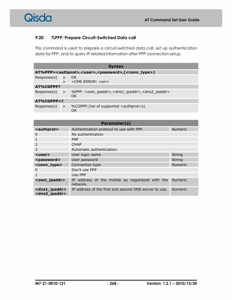
M7-21-0010-121 - 268 - Version: 1.2.1 – 2010/12/30
AT Command Set User Guide
9.20 %PPP: Prepare Circuit-Switched Data call
This command is used to prepare a circuit-switched data call, set up authentication
data for PPP, and to query IP-related information after PPP connection setup.
Syntax
AT%PPP=<authprot>,<user>,<password>,[<conn_type>]
Response(s) � OK � +CME ERROR: <err>
AT%CGPPP?
Response(s) � %PPP: <own_ipaddr>,<dns1_ipaddr>,<dns2_ipaddr> OK
AT%CGPPP=?
Response(s) � %CGPPP:(list of supported <authprot>s) OK
Parameter(s)
<authprot> Authentication protocol to use with PPP. Numeric
0 No authentication
1 PAP
2 CHAP
3 Automatic authentication.
<user> User login name String
<password> User password String
<conn_type> Connection type Numeric
0 Don’t use PPP
1 Use PPP
<own_ipaddr> IP address of the mobile as negotiated with the network.
Numeric
<dns1_ipaddr> <dns2_ipaddr>
IP address of the first and second DNS server to use. Numeric

M7-21-0010-121 - 269 - Version: 1.2.1 – 2010/12/30
AT Command Set User Guide
9.21 %CGREG: GPRS network extended registration
status
This command reports extended information about GPRS network registration state.
%CGREG behaves exactly as +CGREG does. In addition %CGREG supports additional
states as well as an indicator for any activated PDP context.
Syntax
AT%CGREG=[<n>]
Response(s) � OK � +CME ERROR: <err>
AT%CGREG?
Response(s) � %CGREG: <n>,<stat>,[<lac>],[<ci>],[<state>] OK
AT%CGREG=?
Response(s) � %CGREG: (list of supported <n>s) OK
Unsolicited Result Codes
� %CGREG: <stat>,[<lac>],[<ci>],[<state>]
Parameter(s)
<n> Numeric
0 Disable network registration unsolicited result code.
1 Enable network registration unsolicited result code. %CGREG: <stat>
2 Enable network registration and location information unsolicited result code. %CGREG: <stat>[,<lac>,<ci>]
3 Enable network registration, location information and PDP context state. %CGREG: <stat>,[<lac>],[<ci>],<state>
<stat> Numeric
0 Not registered, ME is not currently searching an operator to register to. ME is in GMM state GMM-NULL or GMM-DEREGISTERED-INITIATED. GPRS service is disabled, the ME is allowed to attach to GPRS if requested by the user.
1 Registered, home network. The ME is in GMM state GMM-REGISTERED or GMM-ROUTING-AREA-UPDATING-INITIATED INITIATED on the home PLMN
2 Not registered, but ME is currently trying to attach or searching an operator to register to. The ME is in GMM state GMM-DEREGISTERED or GMM-REGIS-TERED-INITIATED. The GPRS service is enabled, but an allowable PLMN is currently not available. The ME will start a GPRS attach as soon as an allow-able PLMN is available.
M25A M25 M27

M7-21-0010-121 - 270 - Version: 1.2.1 – 2010/12/30
AT Command Set User Guide
3 Registration denied. The ME is in GMM state GMM-NULL. The GPRS service is disabled. The ME is not allowed to attach to GPRS if requested by the user.
4 Unknown
5 Registered, roaming. The ME is in GMM state GMM-REGISTERED or GMM-ROUTING-AREA-UPDATING-INITIATED on a visited PLMN.
6 Limited service (cell might be overloaded) [GPRS suspended]
7 GSM call active [GPRS suspended]
8 No cell available [GPRS suspended]
9 Next attempt to update MS [GPRS suspended]
<lac> Two byte location area code in hexadecimal format String
<ci> Two byte cell ID in hexadecimal format String
<state> Indicates the state of PDP context activation Numeric
0 No PDP context activated.
1 One or more PDP contexts activated.

M7-21-0010-121 - 271 - Version: 1.2.1 – 2010/12/30
AT Command Set User Guide
10 M2M Commands
Please refer to "M2M_User_Guide".

M7-21-0010-121 - 272 - Version: 1.2.1 – 2010/12/30
AT Command Set User Guide
11 SIM Application Toolkit Commands
11.1 %SATM: Set SAT command/response format
This command set the format of the %SATR, %SATE and the unsolicited result codes of
SAT command set. The default format is the hexadecimal string of the PDU of the
proactive command, envelop, and terminal response. The other is the format with
numeric response. For more detail, please refer to “STK User Guide”.
Syntax
AT%SATM=<mode>
Response(s) � OK � +CME ERROR: <err>
AT%SATM?
Response(s) � %SATM: <mode> OK
AT%SATM=?
Response(s) � %SATM: (list of supported<mode>s) OK
Parameter(s)
<mode> Numeric
0 GSM 11.14 PDU mode.
1 Numeric mode.
Example(s)
STK profile download with Numeric format
AT+CSCS=“UCS2” OK AT%SATM=1 OK AT%SATC=1, “7FFFFFFF7F0200FB07” OK AT+CFUN=1 OK %SATI: 37,0,2, “4E2D83EF96FB4FE15340” (Chinese: "中華電信區") %SATI: 37,1, “0065006D006F006D006574068CA1”,33 (Chinese: "emome理財")
1. Change the character set into UCS2.
2. Set Numeric mode. 3. Enable SAT status
report and profile download.
4. Active the SIM card. 5. Menu Select indication
with Numeric format.

M7-21-0010-121 - 273 - Version: 1.2.1 – 2010/12/30
AT Command Set User Guide
%SATI: 37,2, “0065006D006F006D006552A0503C”,33 (Chinese: "emome加值") AT%SATR=37,0
6. SAT response to Setup
Menu command.
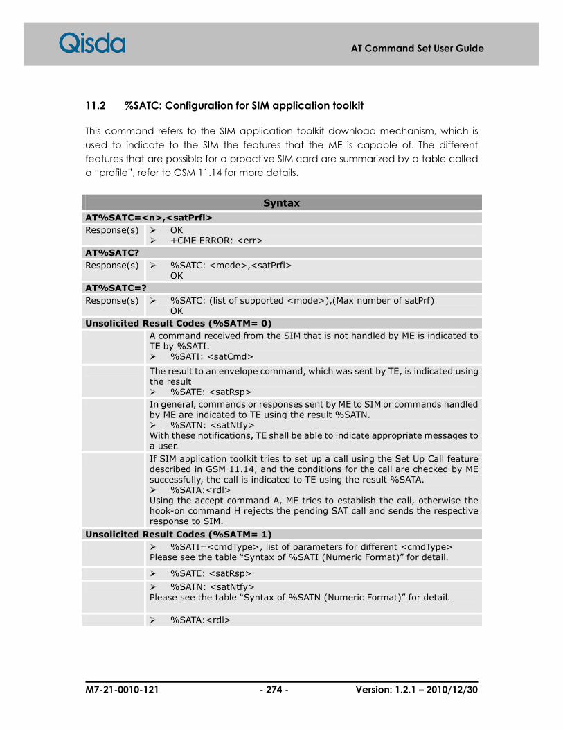
M7-21-0010-121 - 274 - Version: 1.2.1 – 2010/12/30
AT Command Set User Guide
11.2 %SATC: Configuration for SIM application toolkit
This command refers to the SIM application toolkit download mechanism, which is
used to indicate to the SIM the features that the ME is capable of. The different
features that are possible for a proactive SIM card are summarized by a table called
a “profile”, refer to GSM 11.14 for more details.
Syntax
AT%SATC=<n>,<satPrfl>
Response(s) � OK � +CME ERROR: <err>
AT%SATC?
Response(s) � %SATC: <mode>,<satPrfl> OK
AT%SATC=?
Response(s) � %SATC: (list of supported <mode>),(Max number of satPrf) OK
Unsolicited Result Codes (%SATM= 0)
A command received from the SIM that is not handled by ME is indicated to TE by %SATI. � %SATI: <satCmd>
The result to an envelope command, which was sent by TE, is indicated using the result � %SATE: <satRsp>
In general, commands or responses sent by ME to SIM or commands handled by ME are indicated to TE using the result %SATN. � %SATN: <satNtfy> With these notifications, TE shall be able to indicate appropriate messages to a user.
If SIM application toolkit tries to set up a call using the Set Up Call feature described in GSM 11.14, and the conditions for the call are checked by ME successfully, the call is indicated to TE using the result %SATA. � %SATA:<rdl> Using the accept command A, ME tries to establish the call, otherwise the hook-on command H rejects the pending SAT call and sends the respective response to SIM.
Unsolicited Result Codes (%SATM= 1)
� %SATI=<cmdType>, list of parameters for different <cmdType> Please see the table “Syntax of %SATI (Numeric Format)” for detail.
� %SATE: <satRsp>
� %SATN: <satNtfy> Please see the table “Syntax of %SATN (Numeric Format)” for detail.
� %SATA:<rdl>
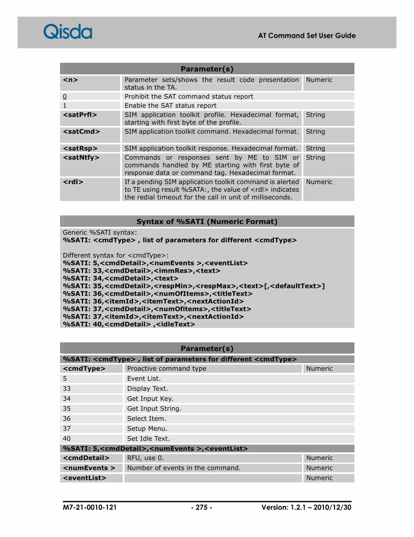
M7-21-0010-121 - 275 - Version: 1.2.1 – 2010/12/30
AT Command Set User Guide
Parameter(s)
<n> Parameter sets/shows the result code presentation status in the TA.
Numeric
0 Prohibit the SAT command status report
1 Enable the SAT status report
<satPrfl> SIM application toolkit profile. Hexadecimal format, starting with first byte of the profile.
String
<satCmd> SIM application toolkit command. Hexadecimal format. String
<satRsp> SIM application toolkit response. Hexadecimal format. String
<satNtfy> Commands or responses sent by ME to SIM or commands handled by ME starting with first byte of response data or command tag. Hexadecimal format.
String
<rdl> If a pending SIM application toolkit command is alerted to TE using result %SATA:, the value of <rdl> indicates the redial timeout for the call in unit of milliseconds.
Numeric
Syntax of %SATI (Numeric Format)
Generic %SATI syntax: %SATI: <cmdType> , list of parameters for different <cmdType> Different syntax for <cmdType>: %SATI: 5,<cmdDetail>,<numEvents >,<eventList> %SATI: 33,<cmdDetail>,<immRes>,<text> %SATI: 34,<cmdDetail>,<text> %SATI: 35,<cmdDetail>,<respMin>,<respMax>,<text>[,<defaultText>] %SATI: 36,<cmdDetail>,<numOfItems>,<titleText> %SATI: 36,<itemId>,<itemText>,<nextActionId> %SATI: 37,<cmdDetail>,<numOfitems>,<titleText> %SATI: 37,<itemId>,<itemText>,<nextActionId> %SATI: 40,<cmdDetail> ,<idleText>
Parameter(s)
%SATI: <cmdType> , list of parameters for different <cmdType>
<cmdType> Proactive command type Numeric
5 Event List.
33 Display Text.
34 Get Input Key.
35 Get Input String.
36 Select Item.
37 Setup Menu.
40 Set Idle Text.
%SATI: 5,<cmdDetail>,<numEvents >,<eventList>
<cmdDetail> RFU, use 0. Numeric
<numEvents > Number of events in the command. Numeric
<eventList> Numeric

M7-21-0010-121 - 276 - Version: 1.2.1 – 2010/12/30
AT Command Set User Guide
0 User activity.
5 Idle screen available.
7 Language selection.
%SATI: 33,<cmdDetail>,<immRes>,<text>
<cmdDetail> bit 1: 0 = normal priority. 1 = high priority. bits 2-7: RFU bit 8: 0 = clear message after a delay. 1 = wait for user to clear message.
Numeric
<immRes> Immediately Response Numeric
0 The ME shall send TERMINAL RESPONSE (Command performed successfully) at the expiration of the short delay.
1 The ME shall send TERMINAL RESPONSE immediately.
<text> String to be displayed.(use the +CSCS character set) String
%SATI: 34,<cmdDetail>,<text>
<cmdDetail> bit 1: 0 = digits (0 9, *, # and +) only 1 = alphabet set; bit 2: 0 = SMS default alphabet 1 = UCS2 alphabet bit 3: 0 = character sets defined by bit 1 and bit 2 are enabled 1 = character sets defined by bit 1 and bit 2 are disabled and the "Yes/No" response is requested bits 4 7: RFU bit 8: 0 = no help information available 1 = help information available
Numeric
<text> Prompt string.(use the +CSCS character set) String
%SATI: 35,<cmdDetail>,<respMin>,<respMax>,<text>,[<defaultText>]
<cmdDetail> bit 1: 0 = digits (0 9, *, #, and +) only 1 = alphabet set bit 2: 0 = SMS default alphabet 1 = UCS2 alphabet bit 3: 0 = ME may echo user input on the display
Numeric

M7-21-0010-121 - 277 - Version: 1.2.1 – 2010/12/30
AT Command Set User Guide
1 = user input shall not be revealed in any way bit 4: 0 = user input to be in unpacked format 1 = user input to be in SMS packed format bits 5 to 7: RFU bit 8: 0 = no help information available 1 = help information available
<respMin> Minimum input length. Numeric
<respMax> Maximum input length. Numeric
<text> Prompt string. (use the +CSCS character set) String
<defaultText> Default input string. (use the +CSCS character set) String
%SATI: 36,<cmdDetail>,<numOfItems>,<titleText> %SATI: 36,<itemId>,<itemText>,<nextActionId> …
<cmdDetail> bit 1: 0 = no selection preference 1 = selection using soft key preferred bits 2 to 7: RFU bit 8: 0 = no help information available 1 = help information available
Numeric
<numOfItems> Number of items in the list. Numeric
<titleText> Title of the menu.(use the +CSCS character set) String
<itemId> Identifier of the item. Numeric
<itemText> Title of the menu.(use the +CSCS character set) String
<nextActionId> Next action identifier. If the bit 3 of <nextActionId> is 1, it is the default action.
Numeric
%SATI: 37,<cmdDetail>,<numOfitems>,<titleText> %SATI: 37,<itemId>,<itemText>,<nextActionId> …
<cmdDetail> bit 1: 0 = no selection preference 1 = selection using soft key preferred bits 2 to 7: RFU bit 8: 0 = no help information available 1 = help information available
Numeric
<numOfItems> Number of menu item in the list. Numeric
<titleText> Title of the menu.(use the +CSCS character set) String
<itemId> Identifier of the menu item. Numeric

M7-21-0010-121 - 278 - Version: 1.2.1 – 2010/12/30
AT Command Set User Guide
<itemText> Title of the menu item.(use the +CSCS character set) String
<nextActionId> Next action identifier. Numeric
%SATI: 40,<cmdDetail> ,<idleText>
<cmdDetail> RFU, use 0. Numeric
<idleText> Text string for the Idle screen.(use the +CSCS character set)
String
Syntax of %SATN (Numeric Format)
Generic %SATI syntax: %SATN: <cmdType>,<cmdDetail>,list of parameters for different <cmdType> Different syntax for <cmdType>: %SATN: 16,<cmdDetail>,<userInfo >,<setupInfo>,<addr> %SATN: 17|18|19|20,<cmdDetail>,<userInfo>
Parameter(s)
%SATN: <cmdType>,<cmdDetail>,list of parameters for different <cmdType>
<cmdType> Proactive command type Numeric
16 Setup Call
17 Setup SS
18 Setup USSD
19 Setup SMS
20 Setup DTMF
%SATN: 16,<cmdDetail>,<userInfo >,<setupInfo>,<addr>
<cmdDetail> Numeric
0 Set up call, but only if not currently busy on another call.
1 Set up call, but only if not currently busy on another call, with redial.
2 Set up call, putting all other calls (if any) on hold.
3 Set up call, putting all other calls (if any) on hold, with redial.
4 Set up call, disconnecting all other calls (if any).
5 Set up call, disconnecting all other calls (if any), with redial.
<userInfo> User information string. String
<setupInfo> Setup information string. String
<addr> Dialing number string. String
%SATN: 17|18|19|20,<cmdDetail>,<userInfo>
<cmdDetail> RFU, use 0. Numeric
<userInfo> User information string. String

M7-21-0010-121 - 279 - Version: 1.2.1 – 2010/12/30
AT Command Set User Guide
Example(s)
STK profile download in PDU mode
AT+CFUN=0 OK AT%SATC=1, “7FFFFFFF7F0200FB07” OK AT+CFUN=1 OK %SATI: “D03E810301250082028182850B804E2D83EF96FB4FE153408F1001800065006D006F006D006574068CA18F1002800065006D006F006D006552A0503C18022121”
1. Disable the SIM card. 2. Profile download and
enable the SAT command status report.
3. Enable the SIM card. 4. Proactive command
indication.
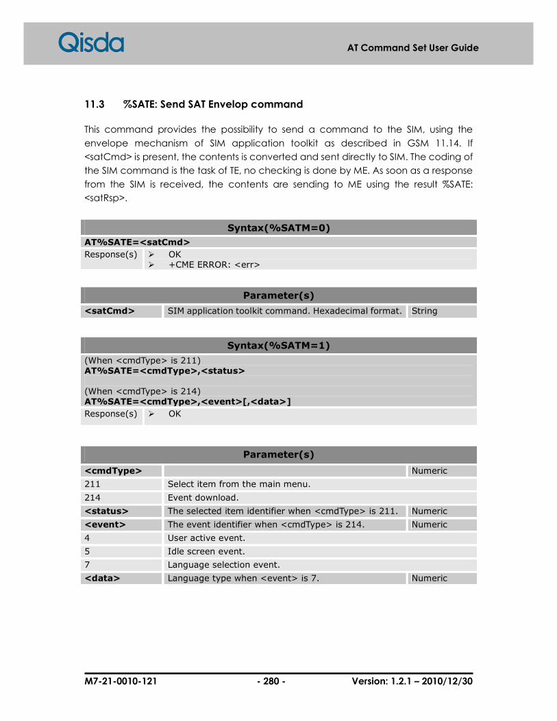
M7-21-0010-121 - 280 - Version: 1.2.1 – 2010/12/30
AT Command Set User Guide
11.3 %SATE: Send SAT Envelop command
This command provides the possibility to send a command to the SIM, using the
envelope mechanism of SIM application toolkit as described in GSM 11.14. If
<satCmd> is present, the contents is converted and sent directly to SIM. The coding of
the SIM command is the task of TE, no checking is done by ME. As soon as a response
from the SIM is received, the contents are sending to ME using the result %SATE:
<satRsp>.
Syntax(%SATM=0)
AT%SATE=<satCmd>
Response(s) � OK � +CME ERROR: <err>
Parameter(s)
<satCmd> SIM application toolkit command. Hexadecimal format. String
Syntax(%SATM=1)
(When <cmdType> is 211) AT%SATE=<cmdType>,<status> (When <cmdType> is 214) AT%SATE=<cmdType>,<event>[,<data>]
Response(s) � OK
Parameter(s)
<cmdType> Numeric
211 Select item from the main menu.
214 Event download.
<status> The selected item identifier when <cmdType> is 211. Numeric
<event> The event identifier when <cmdType> is 214. Numeric
4 User active event.
5 Idle screen event.
7 Language selection event.
<data> Language type when <event> is 7. Numeric

M7-21-0010-121 - 281 - Version: 1.2.1 – 2010/12/30
AT Command Set User Guide
Example(s)
Menu selection (%SATM=0)
AT%SATE =“D309820201819001019500” OK %SATI: “D02C81030124008202818285098091D1878D8CC78A0A8F0A018091D1878D8A9E97F38F0A028091D1878D7C218A0A”
1. Select Menu item 1 2. Next menu items.
Menu selection (%SATM=1)
AT%SATE=211,1 OK %SATE: "" %SATI: 36,0,3,"0065006D006F006D006574068CA1" (Chinese: "emome理財") %SATI: 36,1,"884C52D59280884C",0 (Chinese: "行動銀行") %SATI: 36,2,"884C52D54ED86B3E",0 (Chinese: "行動付款") %SATI: 36,3,"884C52D552385546",0 (Chinese: "行動卷商") AT%SATR=36,16 OK
1. Select Menu item 1 2. Next menu items. 3. Terminated by user.

M7-21-0010-121 - 282 - Version: 1.2.1 – 2010/12/30
AT Command Set User Guide
11.4 %SATR: Send SAT response
This command provides the possibility to send a response to previous received SAT
command. If a SIM application toolkit command was indicated to TE using the result
%SATI: <satCmd>, the TE should send an appropriate response using the %SATR
command. If <satRsp> is present, the contents is converted and sent directly to SIM.
The coding of the SIM response is the task of TE, no checking is done by ME.
Syntax(%SATM=0)
AT%SATR=<cmdType>,<status>[,<data>]
Response(s) � OK � +CME ERROR: <err>
Parameter(s)
<satCmd> SIM application toolkit command. Hexadecimal format. String
Syntax(%SATM=1)
AT%SATR=<satCmd>
Response(s) � OK � +CME ERROR: <err>
Parameter(s)
<cmdType> Response command Numeric
5 Event List.
33 Display Text.
34 Get Input Key.
35 Get Input String.
36 Select Item.
37 Setup Menu.
40 Event List.
<status> Numeric
0 Performed successfully.
16 Terminated by user.
17 Backward move by user.
18 No response from user.
19 Help request from user.
32 ME temporary failure.
<data> Item identifier or input key are numeric type which corresponding to the Select Item and the Get Input Key response.
Numeric, String

M7-21-0010-121 - 283 - Version: 1.2.1 – 2010/12/30
AT Command Set User Guide
String type is for Input string response.(use the +CSCS character set)
<satCmd> SIM application toolkit command. Hexadecimal format. String
Example(s)
Select item from the menu (%SATM=0)
%SATI: “D02C81030124008202818285098091D1878D8CC78A0A8F0A018091D1878D8A9E97F38F0A028091D1878D7C218A0A” AT%SATR=“810301240082028281830100900101” OK
1. Selective items 2. Select item 0
STK menu operations (%SATM=1) (Send a E-mail by STK)
AT+CFUN=0 OK AT+CSCS=“UCS2” OK AT%SATC=1, “7FFFFFFF7F0200FB07” OK AT%SATM=1 OK AT+CFUN=1 OK %SATI: 37,0,2,"4E2D83EF96FB4FE15340" %SATI: 37,1,"0065006D006F006D006574068CA1",0 %SATI: 37,2,"0065006D006F006D006552A0503C",0 AT%SATR=37,0 OK AT+COPS=0 OK AT%SATE=211,2 OK %SATE: "" %SATI: 36,0,11,"0065006D006F006D006552A0503C" %SATI: 36,1,"884C52D55B575178",0 %SATI: 36,2,"003300330033751F6D3B9AD8624B",0 %SATI: 36,3,"0036003600365A1B6A027DB2",0 %SATI: 36,4,"767C96FB5B5090F54EF6",0 %SATI: 36,5,"807D80A17968884C60C5",0 %SATI: 36,6,"770B80A17968884C60C5",0
1. Disable the SIM card. 2. Change the character
set into UCS2. 3. Enable SAT status
report and download the profile string.
4. Set Numeric mode. 5. Active the SIM card. 6. The SAT command: Set
up menu. Menu ID 1-2. 7. SAT response to Setup
Menu command. 8. Register to Network. 9. Select the Menu 2 by
envelop command. 10. %SATE response. 11. The SAT response 11
items in the Menu 2.
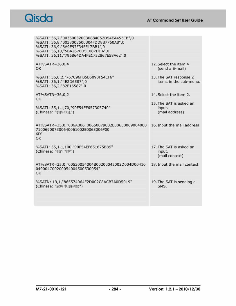
M7-21-0010-121 - 284 - Version: 1.2.1 – 2010/12/30
AT Command Set User Guide
%SATI: 36,7,"003500320030884C52D54EA453CB",0 %SATI: 36,8,"0038003500304FDD8B7760A8",0 %SATI: 36,9,"8A9E97F34FE17BB1",0 %SATI: 36,10,"5BA2670D5C087DDA",0 %SATI: 36,11,"796864DA4FE1752867E58A62",0 AT%SATR=36,0,4 OK %SATI: 36,0,2,"767C96FB5B5090F54EF6" %SATI: 36,1,"4E2D6587",0 %SATI: 36,2,"82F16587",0 AT%SATR=36,0,2 OK %SATI: 35,1,1,70,"90F54EF657305740" (Chinese: "郵件地址") AT%SATR=35,0,"006A006F00650079002E006E0069004000710069007300640061002E0063006F00 6D" OK %SATI: 35,1,1,100,"90F54EF651675BB9" (Chinese: "郵件內容") AT%SATR=35,0,"00530054004B00200045002D004D00410049004C00200054004500530054" OK %SATN: 19,1,"865574064E2D002C8ACB7A0D5019" (Chinese: "處理中,請稍候")
12. Select the item 4
(send a E-mail) 13. The SAT response 2
items in the sub-menu. 14. Select the item 2. 15. The SAT is asked an
input. (mail address)
16. Input the mail address 17. The SAT is asked an
input. (mail context)
18. Input the mail context 19. The SAT is sending a
SMS.

M7-21-0010-121 - 285 - Version: 1.2.1 – 2010/12/30
AT Command Set User Guide
11.5 %SATT: Terminate SAT command or session
This command is used to terminate a SIM application toolkit command or session. If
<cs> is present, the value is coded and sent to the SIM for terminating the command
or session. For example, if a SAT Call Set up was indicated with the result %SATA: 60,
and the redialing time is exceeded, TE shall send the cause 'end of redialing reached'
to ME.
Syntax
AT%SATT=<cs>
Response(s) � OK � +CME ERROR: <err>
Parameter(s)
<cs> Numeric
0 User stopped redialing.
1 End of redialing reached.
2 User ends session.

M7-21-0010-121 - 286 - Version: 1.2.1 – 2010/12/30
AT Command Set User Guide
12 Error Report Commands and Error Code
12.1 +CMEE: Report mobile equipment error
Set command disables or enables the use of result code +CME ERROR: <err> as an
indication of an error relating to the functionality of the ME. When enable, ME related
errors cause +CME ERROR: <err> final result code instead of the regular ERROR final
result code. ERROR is returned normally when error is related to syntax, invalid
parameters, or TA functionality.
Syntax
AT+CMEE=[<n>]
Response(s) � OK
AT+CMEE?
Response(s) � +CMEE: <n> OK
AT+CMEE=?
� (list of supported <n>s) OK
Parameter(s)
<n> Supported audio path Numeric
0 Disable +CME ERROR: <err> result code and use ERROR instead.
1 Enable +CME ERROR: <err> result code and use numeric <err> values.
2 Enable +CME ERROR: <err> result code and use verbose <err> values.

M7-21-0010-121 - 287 - Version: 1.2.1 – 2010/12/30
AT Command Set User Guide
12.2 +CME ERROR: ME error result code
The operation of +CME ERROR:<err> result code is similar to the regular ERROR result
code: if +CME ERROR:<err> is the result code for any of the commands in a command
line, none of the following commands in the same command line is executed.
(neither ERROR nor OK result code shall be returned as a result of a completed
command line execution). The format of <err> can be either numeric or verbose. This
is set with command +CMEE.
Syntax
� +CME ERROR: <err>
Result Code
0 Phone failure
1 No connection to phone
2 Phone-adaptor link reserved
3 Operation not allowed
4 Operation not supported
5 PH-SIM PIN required
6 PH-FSIM PIN required
7 PH-FSIM PUK required
10 SIM not inserted
11 SIM PIN required
12 SIM PUK required
13 SIM failure
14 SIM busy
15 SIM wrong
16 Incorrect password
17 SIM PIN2 required
18 SIM PUK2 required
20 Memory full
21 Invalid index
22 Not found
23 Memory failure
24 Text string too long
25 Invalid characters in text string
26 Dial string too long
27 Invalid characters in dial string
30 No network service
31 Network timeout
32 Network not allowed – emergency calls only
40 Network personalization PIN required

M7-21-0010-121 - 288 - Version: 1.2.1 – 2010/12/30
AT Command Set User Guide
41 Network personalization PUK required
42 Network subset personalization PIN required
43 Network subset personalization PUK required
44 Service provider personalization PIN required
45 Service provider personalization PUK required
46 Corporate personalization PIN required
47 Corporate personalization PUK required
48 File system initial fail
49 Remove file fail
50 Open file fail
51 Read file fail
52 Write file fail
53 Close file fail
54 Create directory fail
55 Open directory fail
56 Write audio setting fail
57 Read audio setting fail
58 Play audio fail
59 Stop playing audio fail
60 Change factory mode setting is not allowed
61 Check type error
62 Allocate memory fail
100 Unknown
103 Illegal MS
106 Illegal ME
107 GPRS service not allowed
111 PLMN not allowed
112 Location not allowed
113 Roaming not allowed in Location Area
132 GPRS service option not supported
133 Requested service option not subscribed
134 Service option temporarily out of order
148 Unspecified GPRS error
149 PDP authentication error
150 Invalid module class
M2M error code
201 parameter not allowed
202 GPRS suspended
203 M2M already activated
204 M2M not activated
205 internal error
206 M2M session is in use
207 No free M2M session
208 M2M session not open
209 other process is running
210 connection already established

M7-21-0010-121 - 289 - Version: 1.2.1 – 2010/12/30
AT Command Set User Guide
211 connection not established
212 TX-buffer space insufficient
213 No data in TX-buffer
214 data format error in hex mode
215 GPRS busy temporarily
216 address or port is already in use
217 server cannot be reached
218 connection is refused by peer
219 size of the data is too large
220 connection has been reset
221 connection has been abort
222 bearer has been disconnected
223 GPRS not ready
224 GPRS bear not ready
225 a similar operation is in progress
226 GPRS connection is already open
250 MMS initial fail
251 MMS deinitial fail
252 MMS not initial, or is sending MMS, or wait the next provision packet
253 Parameter error
254 No free memory
255 Not initial
256 MMS is sending
257 Network error
258 File error
259 Config error
260 Low res
261 Client req
262 Server error
263 Server resp
264 Security error
265 Created
266 Accepted
267 Partial information
268 No response
269 Bad request
270 Unauthorized
271 Payment Required
272 Forbidden
273 No found
274 Internal error
300 Not supported
301 Not ready
302 Memory warning
303 Memory error
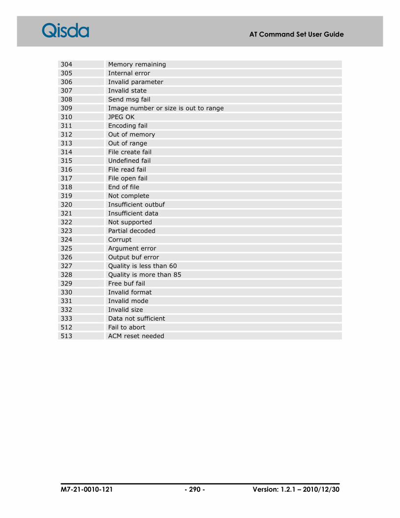
M7-21-0010-121 - 290 - Version: 1.2.1 – 2010/12/30
AT Command Set User Guide
304 Memory remaining
305 Internal error
306 Invalid parameter
307 Invalid state
308 Send msg fail
309 Image number or size is out to range
310 JPEG OK
311 Encoding fail
312 Out of memory
313 Out of range
314 File create fail
315 Undefined fail
316 File read fail
317 File open fail
318 End of file
319 Not complete
320 Insufficient outbuf
321 Insufficient data
322 Not supported
323 Partial decoded
324 Corrupt
325 Argument error
326 Output buf error
327 Quality is less than 60
328 Quality is more than 85
329 Free buf fail
330 Invalid format
331 Invalid mode
332 Invalid size
333 Data not sufficient
512 Fail to abort
513 ACM reset needed

M7-21-0010-121 - 291 - Version: 1.2.1 – 2010/12/30
AT Command Set User Guide
12.3 +CMS ERROR: message service failure result code
Final result code +CMS ERROR: <err> indicates an error related to mobile equipment
or network. The operation is similar to ERROR result code. None of the following
commands in the same command line is executed. Neither ERROR nor OK result code
shall be returned. ERROR is returned normally when error is related to syntax or invalid
parameters.
Syntax
� +CMS ERROR: <err>
Result Code
0…127 GSM 04.11, annex E-2 values
1 Unassigned (unallocated) number
8 Operator determined barring
10 Call barred
21 Short message transfer rejected
27 Destination out of service
28 Unidentified subscriber
29 Facility rejected
30 Unknown subscriber
38 Network out of order
41 Temporary failure
42 Congestion
47 Resources unavailable, unspecified
50 Requested facility not subscribed
69 Requested facility not implemented
81 Invalid short message transfer reference value
95 Semantically incorrect message
96 Invalid mandatory information
97 Message type non-existent or not implemented
98 Message not compatible with short message protocol state
99 Information element non-existent or not implemented
111 Protocol error, unspecified
127 Interworking, unspecified
128…255 TP Failure-Cause(TP-FCS) values according to GSM 03.40
128 Telematic interworking not supported
129 Short message Type 0 not supported
130 Cannot replace short message
143 Unspecified TP-PID error
144 Data coding scheme not supported
145 Message class not supported
159 Unspecified TP-DCS error

M7-21-0010-121 - 292 - Version: 1.2.1 – 2010/12/30
AT Command Set User Guide
160 Command cannot be actioned
161 Command unsupported
175 Unspecified TP command error; either the message type identifier is other than SMS command, or the service center address is corrupt
176 TPDU not supported
192 SC busy
193 No SC subscription
194 SC system failure
195 Invalid SME address
196 Destination SME barred
197 SM rejected-duplicate SM
198 TP-VPF not supported
199 TP-VP not supported
208 SIM SMS storage full
209 No SMS storage capability in SIM
210 Error in MS
211 Memory capacity exceeded
255 Unspecified error cause
300 ME failure
301 SMS service of ME reserved
302 Operation not allowed
303 Operation not supported
304 Invalid PDU mode parameter
305 Invalid text mode parameter
310 SIM not inserted
311 SIM PIN required
312 PH-SIM PIN required
313 SIM failure
314 SIM busy
315 SIM wrong
316 SIM PUK required
317 SIM PIN2 required
318 SIM PUK2 required
320 Memory failure
321 Invalid memory index
322 Memory full
330 SMSC address unknown
331 No network service
332 Network timeout
340 No +CNMA acknowledgement expected
500 Unknown error
…511 Other values within the range from 256 to 511 are reserved
512 Fail to abort
513 ACM reset needed
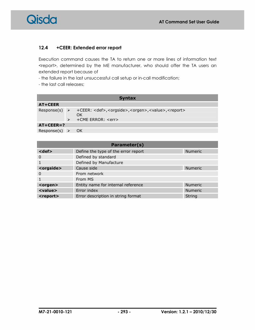
M7-21-0010-121 - 293 - Version: 1.2.1 – 2010/12/30
AT Command Set User Guide
12.4 +CEER: Extended error report
Execution command causes the TA to return one or more lines of information text
<report>, determined by the ME manufacturer, who should offer the TA users an
extended report because of
- the failure in the last unsuccessful call setup or in-call modification;
- the last call releases;
Syntax
AT+CEER
Response(s) � +CEER: <def>,<orgside>,<orgen>,<value>,<report> OK
� +CME ERROR: <err>
AT+CEER=?
Response(s) � OK
Parameter(s)
<def> Define the type of the error report Numeric
0 Defined by standard
1 Defined by Manufacture
<orgside> Cause side Numeric
0 From network
1 From MS
<orgen> Entity name for internal reference Numeric
<value> Error index Numeric
<report> Error description in string format String
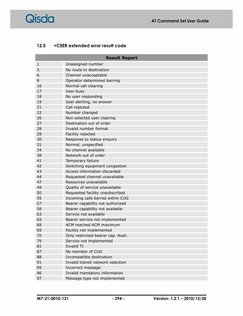
M7-21-0010-121 - 294 - Version: 1.2.1 – 2010/12/30
AT Command Set User Guide
12.5 +CEER extended error result code
Result Report
1 Unassigned number
3 No route to destination
6 Channel unacceptable
8 Operator determined barring
16 Normal call clearing
17 User busy
18 No user responding
19 User alerting, no answer
21 Call rejected
22 Number changed
26 Non selected user clearing
27 Destination out of order
28 Invalid number format
29 Facility rejected
30 Response to status enquiry
31 Normal, unspecified
34 No channel available
38 Network out of order
41 Temporary failure
42 Switching equipment congestion
43 Access information discarded
44 Requested channel unavailable
47 Resources unavailable
49 Quality of service unavailable
50 Requested facility unsubscribed
55 Incoming calls barred within CUG
57 Bearer capability not authorized
58 Bearer capability not available
63 Service not available
65 Bearer service not implemented
68 ACM reached ACM maximum
69 Facility not implemented
70 Only restricted bearer cap. Avail.
79 Service not implemented
81 Invalid TI
87 No member of CUG
88 Incompatible destination
91 Invalid transit network selection
95 Incorrect message
96 Invalid mandatory information
97 Message type not implemented
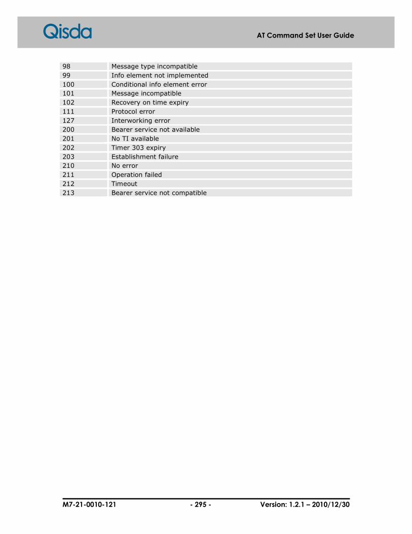
M7-21-0010-121 - 295 - Version: 1.2.1 – 2010/12/30
AT Command Set User Guide
98 Message type incompatible
99 Info element not implemented
100 Conditional info element error
101 Message incompatible
102 Recovery on time expiry
111 Protocol error
127 Interworking error
200 Bearer service not available
201 No TI available
202 Timer 303 expiry
203 Establishment failure
210 No error
211 Operation failed
212 Timeout
213 Bearer service not compatible

M7-21-0010-121 - 296 - Version: 1.2.1 – 2010/12/30
AT Command Set User Guide
12.6 +EXT ERROR: extended error result code
Syntax
� +EXT ERROR: <err>
Result Code
1 Parameter not allowed
2 Data corrupted
3 Internal error
4 Call table full
5 Service table full
6 Call not found
7 No data-call supported
8 One call on hold
9 Hold call not supported for this type
10 Number not allowed by FDN
11 Number not allowed by BDN
12 Parallel USSD not supported
13 Fax minimum speed condition
14 Conflict with command details
15 Not allowed by ALS-Lock
16 IMEI illegal
100 Other error


![ESC/POS Command Manual - Support Technique AURES ESCPOS.pdf · ESC/POS Command Manual 3 Command Descriptions Command Notation [Name] The name of the control command. [Format] The](https://static.fdocuments.in/doc/165x107/5a9d989d7f8b9a21688cc662/escpos-command-manual-support-technique-escpospdfescpos-command-manual-3-command.jpg)