
M2 Antenna Systems, Inc. Model No: 40M4CDD MANUALS/40MANTS... · ware for tightness BEFORE it...
17
M2 Antenna Systems, Inc. 4402 N. Selland Ave. Fresno, CA 93722 Tel: (559) 432-8873 Fax: (559) 432-3059 Web: www.m2inc.com ©2018 M2 Antenna Systems Incoporated 3/28/18 REV A Model ......................................... 40M4CDD Frequency Range ....................... 7.0-7.3 MHz continuous Typical gain ................................ 11.75 @ 70’ dBi typical Front to back ratio ...................... 22 dB typical Beamwidth ............................... 75° Feed type / Balun ....................... SO-239 / 1:1 Balun Feed Impedance. ....................... 50 Ohms VSWR......................................... 1.2:1 typical, 2.0:1 max Connector ...................................SO-239, Other avl. Power Handling ..........................3 Kw, Higher avl. Boom Length / Dia ......................50’ / 3” X .125 Maximum Element Length..........49’ Turning Radius: ..........................34’ Mast Size ....................................2” or 3” Nom. Wind area / Survival ...................13.0 Sq. Ft. / 100 MPH M2 Antenna Systems, Inc. Model No: 40M4CDD SPECIFICATIONS: *Subtract 2.14 from dBi for dBd / FS = Free Space FEATURES: Recently, M2 engineers developed a new way to make coils using CNC tooling. The result is a precision inductor increasing Q and lowering loss to new levels. A coil loaded Yagi design was computer optimized, and not one single change was required on the finished Yagi. This design gets the bandwidth and maintains performance across the band like no other 40 meter Yagi. Gain, Front to Back and VSWR are maintained nearly flat across the 7.0 to 7.2 MHz band section. Mechanically it is easy to assemble. Only the tips of each element are different as all the coils are the same for each element. The coils themselves float in air minimizing dielectric loss. They are fully covered with a husky polyethylene cov- er. Each end of the coil uses a massive 3.75” full circumference solid connection. Two tuning options are available; 7.0- 7.2 or 7.1-7.3 but still broadband. The resulting design is head and shoulders above the competition in strength, dura- bility and performance. This antenna has been designed to meet your contesting needs and give you years of enjoy- ment on the 40 meter band. Remember foreign broadcast is now gone below 7.2 MHz and foreign hams can now transmit all the way to 7.2 MHz on phone and CW. 40M is now a spectacular worldwide DX band! If you haven’t tried 40M lately, you are in for a treat! Mechanically, the elements are identical to it’s older brother, the 40M4LLDD. The 40M4C can also withstand continuous winds of 100 mph or the constant battering of high winds . This antenna too, WILL frustrate Mother Nature! The 3 kW continuous, 5 kW peak, 1:1 balun completes the package.
Transcript of M2 Antenna Systems, Inc. Model No: 40M4CDD MANUALS/40MANTS... · ware for tightness BEFORE it...

M2 Antenna Systems, Inc. 4402 N. Selland Ave. Fresno, CA 93722 Tel: (559) 432-8873 Fax: (559) 432-3059 Web: www.m2inc.com
©2018 M2 Antenna Systems Incoporated
3/28/18 REV A
Model ......................................... 40M4CDD Frequency Range ....................... 7.0-7.3 MHz continuous Typical gain ................................ 11.75 @ 70’ dBi typical Front to back ratio ...................... 22 dB typical Beamwidth ............................... 75° Feed type / Balun ....................... SO-239 / 1:1 Balun Feed Impedance. ....................... 50 Ohms
VSWR ......................................... 1.2:1 typical, 2.0:1 max
Connector ................................... SO-239, Other avl. Power Handling .......................... 3 Kw, Higher avl. Boom Length / Dia ...................... 50’ / 3” X .125 Maximum Element Length .......... 49’ Turning Radius: .......................... 34’ Mast Size .................................... 2” or 3” Nom. Wind area / Survival ................... 13.0 Sq. Ft. / 100 MPH
M2 Antenna Systems, Inc. Model No: 40M4CDD
SPECIFICATIONS:
*Subtract 2.14 from dBi for dBd / FS = Free Space
FEATURES: Recently, M2 engineers developed a new way to make coils using CNC tooling. The result is a precision inductor increasing Q and lowering loss to new levels. A coil loaded Yagi design was computer optimized, and not one single change was required on the finished Yagi. This design gets the bandwidth and maintains performance across the band like no other 40 meter Yagi. Gain, Front to Back and VSWR are maintained nearly flat across the 7.0 to 7.2 MHz band section. Mechanically it is easy to assemble. Only the tips of each element are different as all the coils are the same for each element. The coils themselves float in air minimizing dielectric loss. They are fully covered with a husky polyethylene cov-er. Each end of the coil uses a massive 3.75” full circumference solid connection. Two tuning options are available; 7.0-7.2 or 7.1-7.3 but still broadband. The resulting design is head and shoulders above the competition in strength, dura-bility and performance. This antenna has been designed to meet your contesting needs and give you years of enjoy-ment on the 40 meter band. Remember foreign broadcast is now gone below 7.2 MHz and foreign hams can now transmit all the way to 7.2 MHz on phone and CW. 40M is now a spectacular worldwide DX band! If you haven’t tried 40M lately, you are in for a treat! Mechanically, the elements are identical to it’s older brother, the 40M4LLDD. The 40M4C can also withstand continuous winds of 100 mph or the constant battering of high winds . This antenna too, WILL frustrate Mother Nature! The 3 kW continuous, 5 kW peak, 1:1 balun completes the package.

40M4CDD ANTENNA OVERVIEW
BEFORE YOU BEGIN: Look over all the DRAWINGS to get familiar with the various parts and assem-blies in the system. Tools handy for assembly process: screwdriver, 11/32”, 7/16”, 1/2”, 9/16” and 5/8” spin-tites, end wrenches and/or sockets, and a measuring tape. Note: All installations are unique in some way, which means it's OK to preassemble certain hardware, or
rearrange the assembly process to meet specific site requirements. A quick review of the assembly drawings should help firm up the appropriate strategy. Please remember to double-check all hard-ware for tightness BEFORE it becomes inaccessible.
One container of zinc paste (Penetrox, Noalox, or equiv.) has been provided to enhance and maintain the quality of all mechanical and electrical junctions on this system. Apply a thin coat wherever two pieces of aluminum come in contact or any other electrical connections are made. It is also useful on screws and bolt threads as an ANTI SEIZE compound.
REFLECTOR
REAR DRIVEN ELEMENT
FRONT DRIVEN ELEMENT
DIRECTOR
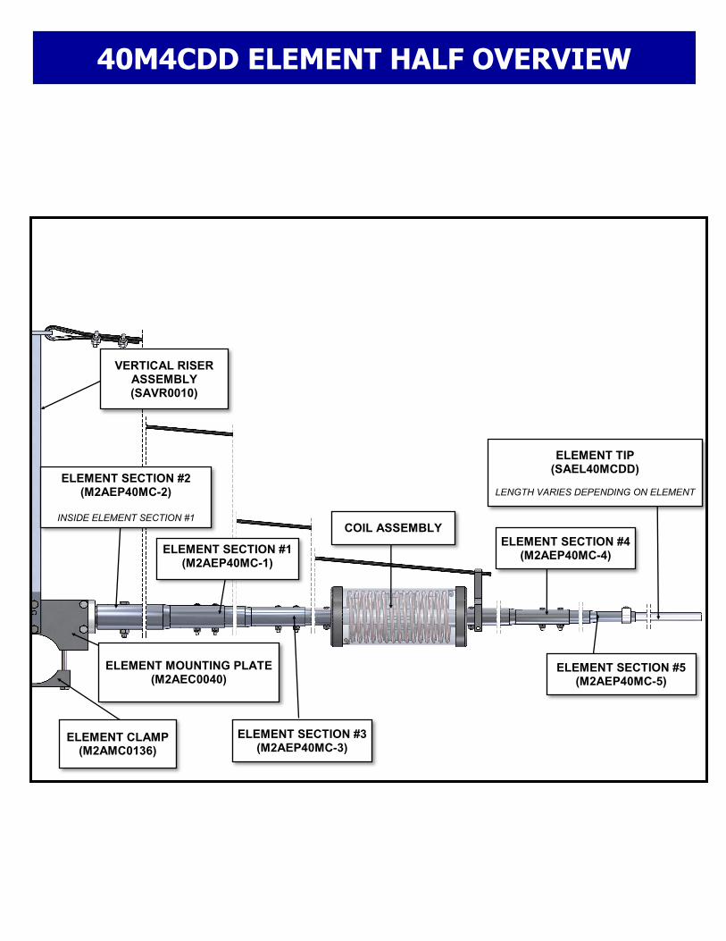
40M4CDD ELEMENT HALF OVERVIEW
ELEMENT CLAMP (M2AMC0136)
ELEMENT MOUNTING PLATE (M2AEC0040)
ELEMENT SECTION #1 (M2AEP40MC-1)
ELEMENT SECTION #2 (M2AEP40MC-2)
INSIDE ELEMENT SECTION #1
ELEMENT SECTION #4 (M2AEP40MC-4)
ELEMENT SECTION #3 (M2AEP40MC-3)
ELEMENT SECTION #5 (M2AEP40MC-5)
COIL ASSEMBLY
ELEMENT TIP (SAEL40MCDD)
LENGTH VARIES DEPENDING ON ELEMENT
VERTICAL RISER ASSEMBLY (SAVR0010)

40M4CDD COIL OVERVIEW
40M COIL (M2ACA1550)
COIL SUPPORT (M2ACA1554)
COIL INSULATOR (M2AFG0050)
COIL POST (M2ACA1551)
(QTY 2)
ELEMENT ADAPTER TUBE (M2ACA156)
COIL END CAP (M2ACA1552)
(QTY 2)
ELEMENT SECTION (M2AEP40MC-4)
NOTE: COVER REMOVED FOR ILLUSTRATION PURPOSES.
CROSS BOOM ELEMENT TIP

40M4CDD CROSS BOOM OVERVIEW
REFLECTOR ELEMENT
REAR DRIVEN ELEMENT
FRONT DRIVEN ELEMENT
DIRECTOR ELEMENT
2” MAST SUPPLIED BY CUSTOMER
TURNBUCKLE PLATE
RECOMMENDED DISTANCE ABOVE ANTENNA 2’ - 4’
BOOM TO MAST PLATE
PHASING LINES (QTY 2) 3/8” EYEBOLT 3/8” EYEBOLT
REAR SUPPORT CABLE
APPROX. 20’ (240”)
FRONT SUPPORT CABLE
APPROX. 18’ (216”)
NOTE: ONLY HALF OF THE ELEMENT IS SHOWN. THE OTHER SIDE IS THE MIRROR IMAGE OF THE ILLUSTRATION SHOWN.
3/8” TURNBUCKLE (QTY 2)

40M4CDD COIL ASSEMBLY INSTRUCTIONS
STEP 1: Slide the COIL SUPPORT onto the 7/8” COIL INSULATOR. Final position will be done later in the assembly process. STEP 2: The COIL is wound tight at the factory to prevent damage dur-ing shipping. Use the COIL SPREADING TOOL provided and carefully insert it into the first turn of the COIL. Now gently push or roll the tool through all 15.5 turns of the COIL. Now the COIL is nearly in its final shape and is ready to be threaded onto the COIL SUPPORT. STEP 3: Use pliers to gently straighten the last 1/2” of the COIL slightly and file off any burrs. STEP 4: Begin threading the COIL onto one end of the COIL SUPPORT. BE CAREFUL to not deform the COIL during this process. The COIL should thread smoothly. Continue until about 5-1/2 turns are past the COIL SUPPORT. NOTE: PENETROX PASTE FOR LUBRICATING SCREW THREADS AND TUBING JOINTS HAS BEEN SUPPLIED. USE A VERY SMALL AMOUNT ON EACH SCREW THREAD AND UNDER THE COIL POSTS DURING THE NEXT OPERATION. STEP 5: Be sure you have 15.5 turns. First rotate the COIL and the COIL SUPPORT so the leading end of the COIL goes over and just past the inner hole in the COIL INSULATOR. Now slide on one COIL POST so it is right over the first hole. Next, carefully slide on the ELE-MENT ADAPTER TUBE and align it so both holes in the tube match the two holes in the COIL INSULATOR. STEP 6: Insert hardware through the ELEMENT ADAPT-ER TUBE and the COIL INSULATOR and begin thread-ing it into the COIL POST. Tighten hardware. Thread the SET SCREW into the top of the COIL POST and with about 1/2” of wire protruding past the COIL POST, tighten the SET SCREW gently. Use supplied ALLEN WRENCH to tighten the SET SCREW. STEP 7: The second COIL POST is mounted on the OPPOSITE SIDE of the COIL INSULATOR so 15 1/2 turns of the COIL are used. A small amount of the COIL should pass over the COIL INSULATOR hole. Slide on the second COIL POST and align it over the hole. Slide on ELEMENT SECTION #4 TUBE. Fasten the COIL POST to the tubing assembling using the supplied hardware. STEP 8: Insert the SET SCREW into the COIL POST and tighten gently. Adjust the COIL and COIL SUPPORT location for equally spaced turns. The distance between each turn should be the same as the COIL diameter. Once the COIL is straight and aligned, tighten the final SET SCREW securely.
COIL (15.5 TURNS) (M2ACA1550)
COIL INSULATOR (M2AFG0050)
COIL SUPPORT (M2ACA1554)
ELEMENT SECTION #4 (M2AEP40MC-4)
ELEMENT ADAPTER TUBE
(M2ACA1556)
COIL POST (M2ACA1551)
SCREW, 8-32 X 1-1/4” SET SCREW, 1/4-20 X 1/4”
COIL POST (M2ACA1551)
SCREW, 8-32 X 1-1/4” SET SCREW, 1/4-20 X 1/4”
40M4CDD COIL ASSEMBLY INSTRUCTIONS
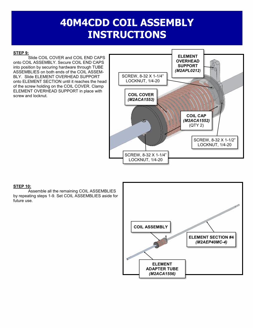
STEP 9: Slide COIL COVER and COIL END CAPS onto COIL ASSEMBLY. Secure COIL END CAPS into position by securing hardware through TUBE ASSEMBLIES on both ends of the COIL ASSEM-BLY. Slide ELEMENT OVERHEAD SUPPORT onto ELEMENT SECTION until it reaches the head of the screw holding on the COIL COVER. Clamp ELEMENT OVERHEAD SUPPORT in place with screw and locknut. STEP 10: Assemble all the remaining COIL ASSEMBLIES by repeating steps 1-9. Set COIL ASSEMBLIES aside for future use.
SCREW, 8-32 X 1-1/4” LOCKNUT, 1/4-20
SCREW, 8-32 X 1-1/4” LOCKNUT, 1/4-20
SCREW, 8-32 X 1-1/2” LOCKNUT, 1/4-20
COIL COVER (M2ACA1553)
ELEMENT OVERHEAD SUPPORT
(M2APL0212)
COIL ASSEMBLY
ELEMENT ADAPTER TUBE
(M2ACA1556)
ELEMENT SECTION #4 (M2AEP40MC-4)
COIL CAP (M2ACA1552)
(QTY 2)
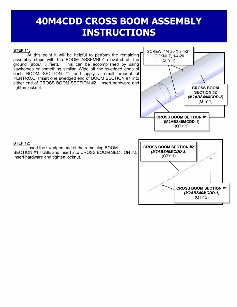
STEP 11:
At this point it will be helpful to perform the remaining assembly steps with the BOOM ASSEMBLY elevated off the ground (about 3 feet). This can be accomplished by using sawhorses or something similar. Wipe off the swedged ends of each BOOM SECTION #1 and apply a small amount of PENTROX. Insert one swedged end of BOOM SECTION #1 into either end of CROSS BOOM SECTION #2. Insert hardware and tighten locknut. STEP 12:
Insert the swedged end of the remaining BOOM SECTION #1 TUBE and insert into CROSS BOOM SECTION #2. Insert hardware and tighten locknut.
SCREW, 1/4-20 X 3-1/2” LOCKNUT, 1/4-20
(QTY 4)
CROSS BOOM SECTION #1 (M2ABS40MCDD-1)
(QTY 2)
CROSS BOOM SECTION #2
(M2ABS40MCDD-2) (QTY 1)
40M4CDD CROSS BOOM ASSEMBLY INSTRUCTIONS
CROSS BOOM SECTION #1 (M2ABS40MCDD-1)
(QTY 2)
CROSS BOOM SECTION #2 (M2ABS40MCDD-2)
(QTY 1)

STEP 13: Start at one end of the CROSS BOOM ASSEM-BLY. It does not matter which end, as the REFLECTOR ELEMENT and DIRECTOR ELEMENT are assembled with the same parts. Clamp one set of the ELEMENT MOUNTING PLATE 1” from the end of the CROSS BOOM ASSEMBLY. STEP 14: Center and clamp the ELEMENT CENTER SPLICE between two ELEMENT MOUNTING PLATES. Make sure the ELEMENT TUBE mounting holes are ori-ented vertically. NOTE: The ELEMENT HALVES are symmetrical on both sides. Do each of the following steps on both sides of the ELEMENT.
STEP 15: Slide ELEMENT SECTION #2 onto ELEMENT CENTER SPLICE. Slide on DISC INSULATOR. Push DISC INSULATOR against ELEMENT CLAMP.
BOLT, 1/4-20 X 2-3/4” LOCKNUT, 1/4-20
(QTY 4)
ELEMENT CLAMP (M2AMC0136)
(QTY 2)
40M4CDD REFLECTOR/DIRECTOR ELEMENT MOUNT ASSEMBLY INSTRUCTIONS
1”
ELEMENT MOUNTING PLATE
(M2AEC0040) (QTY 2)
CROSS BOOM SECTION #1 (M2ABS40MCDD-1)
BOLT, 1/4-20 X 2-1/2” LOCKNUT, 1/4-20
(QTY 4)
ELEMENT CENTER SPLICE
(M2ASR0050)
DISC INSULATOR (M2ADI0020)
ELEMENT SECTION #2 (M2AEP40MC-2)

STEP 16: Slide ELEMENT SECTION #1 onto ELEMENT SECTION #2. Insert hardware and tighten locknut. Attach VERTICAL RISER ASSEMBLY.
STEP 17: Insert ELEMENT SECTION #3 into the end of ELEMENT SECTION #1. Insert and tighten hardware.
40M4CDD REFLECTOR/DIRECTOR ASSEMBLY INSTRUCTIONS
ELEMENT SECTION #1 (M2AEP40MC-1)
BOLT, 1/4-20 X 2” LOCKNUT, 1/4-20
BOLT, 1/4-20 X 3-1/2” LOCKNUT, 1/4-20
(QTY 2)
VERTICAL RISER ASSEMBLY (SAVR0010)
ELEMENT SECTION #1 (M2AEP40MC-1)
ELEMENT SECTION #3 (M2AEP40MC-3)
SCREW, 8-32 X 1-3/4” LOCKNUT, 8/32
(QTY 2)

STEP 18: Insert the ELEMENT ADAPTER TUBE of the COIL ASSEMBLY previous assembled in STEPS 1-10 into ELEMENT SECTION #3. Insert and tighten hard-ware.
STEP 19: Insert ELEMENT SECTION #5 into the end of ELEMENT SECTION #4. Insert and tighten hardware.
40M4CDD REFLECTOR/DIRECTOR ASSEMBLY INSTRUCTIONS
COIL ASSEMBLY SCREW, 8-32 X 1-1/2” LOCKNUT, 8-32
(QTY 2)
ELEMENT SECTION #4 (M2AEP40MC-4)
ELEMENT SECTION #5 (M2AEP40MC-3)
SCREW, 8-32 X 1-1/4” LOCKNUT, 8/32
(QTY 2)
ELEMENT SECTION #3 (M2AEP40MC-3)
ELEMENT ADAPTER TUBE
(M2ACA1556)
COIL ASSEMBLY

40M4CDD REFLECTOR/DIRECTOR ASSEMBLY INSTRUCTIONS
STEP 20: To be able to adjust the ELEMENT TIP tubing a COMPRESSION CLAMP is used. First thread on the hex nut to capture the screw in the CLAMP. Then slid the COMPRESSION CLAMP such the screw is lined up with the hole in ELEMENT SECTION #5. Use the DIMENSION SHEET and set the proper exposed length of the ELE-MENT STEP 21: Repeat STEPS 13-19 for the DIRECTOR ELE-MENT ASSEMBLY. Mount on the other end of the CROSS BOOM ASSEMBLY 1” from the end.
ELEMENT SECTION #5 (M2AEP40MC-3)
SCREW, 8-32 X1/2” HEX NUT, 8-32
(QTY 1)
COMPRESSION CLAMP
ELEMENT TIP (SAEL40M4CDD)
REFLECTOR ELEMENT
CROSS BOOM ASSEMBLY
DIRECTOR ELEMENT

STEP 22: The DRIVEN ELEMENT MOUNTS are very simi-lar to the REFLECTOR and DIRECTOR MOUNTS. The only difference is the ELEMENT CENTER SPICE is re-placed with a non-conductive fiberglass rod. Build the REAR and FRONT DRIVEN ELEMENTS using the DI-MENSION SHEET to determine final position. Insert the INSULATOR with the holes vertically oriented. Center and clamp the INSULATOR between two ELEMENT MOUNT-ING PLATES.
STEP 23: Slide ELEMENT SECTION #2 onto ELEMENT CENTER SPLICE. Slide on DISC INSULATOR. Push DISC INSULATOR against ELEMENT CLAMP.
BOLT, 1/4-20 X 2-3/4” LOCKNUT, 1/4-20
(QTY 4)
40M4CDD DRIVEN ELEMENT MOUNT ASSEMBLY INSTRUCTIONS
ELEMENT MOUNTING PLATE
(M2AMC0040) (QTY 2)
CROSS BOOM SECTION #2 (M2ABS40MCDD-2)
ELEMENT CLAMP (M2AMC0136)
(QTY 2)
BOLT, 1/4-20 X -1/2” LOCKNUT, 1/4-20
(QTY 4)
DISC INSULATOR (M2ADI0020)
ELEMENT SECTION #2 (M2AEP40MC-2)
INSULATOR (M2AFG0034)

STEP 24: Slide ELEMENT SECTION #1 onto ELEMENT SECTION #2. Slide PHASING LINE CLAMP CAP against DISC INSULATOR. Then slide on PHASING LINE CLAMP. Fasten parts together with countersunk bolt. Tighten PHASING LANE CLAMP to ELEMENT SECTION #1 with screw. Insert bolt into ELEMENT SECTION #1 through ELEMENT SECTION #2. Tighten nut.
STEP 25: Fasten VERTICAL RISER to ELEMENT CLAMP PLATE. STEP 26: Continue building the rest of the DRIVEN ELE-MENT by following STEPS 17-20. STEP 27: Follow STEPS 22-26 to build second DRIVEN ELEMENT. Use DIMENSION SHEET for final location.
40M4CDD DRIVEN ELEMENT ASSEMBLY INSTRUCTIONS
ELEMENT SECTION #1 (M2AEP40MC-1)
BOLT, 1/4-20 X 2” LOCKNUT, 1/4-20
PHASING LINE CLAMP CAP (M2APL0067)
PHASING LINE CLAMP (M2APL0035)
COUNTERSUNK BOLT, 1/4-20 X 1” LOCKNUT, 1/4-20
SCREW, 8-32 X 2” LOCKNUT, 8-32
BOLT, 1/4-20 X 3-1/2” LOCKNUT, 1/4-20
(QTY 2)
VERTICAL RISER ASSEMBLY (SAVR0010)

STEP 27: The PHASING CABLES are two 3/16” bent alumi-num rod equally spaced apart with Delrin STANDOFFS. Slide the two aluminum PHASING LINES into the 5 Delrin PHASING LINE STANDOFFS. If you bend the PHASING LINES first you will not be able to slide on the STAND-OFFS. Zip tie the STANDOFFS to the CROSS BOOM equally spaced apart between the FRONT and REAR DRIVEN ELEMENTS.
STEP 28: Bend PHASING LINES using drawing as an approximate guide.
STEP 29: Insert PHASING LINES into DRIVEN ELEMENT MOUNTS. Tighten nuts.
40M4CDD PHASING CABLE ASSEMBLY INSTRUCTIONS
FRONT OF ANTENNA
REAR OF ANTENNA
COUNTERSUNK BOLT, 1/4-20 X 1” LOCKNUT, 1/4-20
UPPER PHASING LINE
LOWER PHASING LINE
PHASING LINE STANDOFF

40M4CDD–50 DIMENTION SHEET
ELEMENT SPACING
EXPOSED TIP LENGTH
0.0
232.00”
356.00”
596.00”
124.00”
240.00”
232.00”
49.50”
45.50”
36.00”
29.25”
250” APROXIMATE
BTM POSITION
36” EYE BOLT
36” EYE BOLT

40M4CDD PARTS & HARDWARE DESCRIPTION QTY BOOM SECTION #1, 3.0” X .125” X 180”, SOE (M2ABS40M4CDD-1) ............................................................. 2 BOOM SECTION #2, 3.0” X .125” X 156” (M2ABS40M4CDD-2) ...................................................................... 1 ELEMENT SECTION #1: 1-1/2” X .058” X 60”, SOE (M2AEP40MC-1) ............................................................. 8 ELEMENT SECTION #2: 1-3/8” X .058” X 23.812” (M2AEP40MC-2) ............................................................... 8 ELEMENT SECTION #3: 1” X .058” X 60”, SOE (M2AEP40MC-3) ................................................................... 8 ELEMENT SECTION #4: 1” X .058” X 60”, SOE (M2AEP40MC-4) ................................................................... 8 ELEMENT SECTION #5: 3/4” X .049” X 48”, SOE (M2AEP40MC-5) ................................................................ 8 ELEMENT TIP ASSEMBLY, 1/2” X .049” X SEE DIMENSION SHEET (SAEL40MCDD) ................................. 8 ELEMENT CENTER SPLICE, 1.25” X 24”, ALUMINUM ROD (M2ASR0050) ................................................... 2 INSULATOR, 1.25” X 24”, FIBERGLASS ROD (M2AFG0034) ......................................................................... 2 ELEMENT MOUNTING PLATE, 3” X 6” X .500”, ALUMINUM (M2AEC0040) ................................................... 8 DISC INSULATOR, POLYETHYLENE, 2” OD (M2ADI0020) ............................................................................ 8 ELEMENT CLAMP, 1” X 4” X .500”, ALUMINUM (M2AMC0136) ...................................................................... 8 PHASE LINE CLAMP, 1.75” X 2.625” X .375” (M2APL0035) ............................................................................ 4 PHASE LINE CLAMP CAP, 1.250” X .750” X .250” (M2APL0067) .................................................................... 4 PHASE LINE STANDOFF, .625” X 2.5”, DELRIN ROD ( M2ASO0050) ............................................................ 5 PHASE LINE, 3/16” X 130”, ALUMINUM ROD .................................................................................................. 2 COMPRESSION CLAMP, 5/8” ......................................................................................................................... 8 VERTICAL RISER ASSEMBLY (M2AVR0010) ................................................................................................. 4 DACRON ROPE, 1/8” X 112’ (1344”) ................................................................................................................ 1 40M COIL, 15 1/2 TURNS (M2ACA1550) ......................................................................................................... 8 COIL POST, .500” X .500” X 1.187”, ALUMINUM (M2ACA1551) ...................................................................... 16 COIL END CAP, 3.625” X .625”, UMHW (M2ACA1552) ................................................................................... 16 COIL COVER, 3.290” X 7.250”, POLYETHYLENE TUBE (M2ACA1553) ......................................................... 8 COIL SUPPORT, 2.937” X 1.75”, POLYETHYLENE (M2ACA1554) ................................................................. 8 ELEMENT ADAPTER TUBE, 40M COIL, 1” X .058” X 24”, ALUMINUM (M2ACA1556) ................................... 8 ELEMENT OVERHEAD SUPPORT, 1.250” X 3.750” X .375”, ALUMINUM (M2APL0212) ............................... 8 COIL INSULATOR, .875” X 10.625”, FIBERGLASS (M2AFG0050) .................................................................. 8 BOOM TO MAST PLATE, 8” X 8” X .250”, ALUMINUM (M2APT0070) ............................................................. 1 TURN BUCKLE PLATE, 2” X 5” X .188”, ALUMINUM (M2APT0113) ............................................................... 1 PENETROX / ZINC PASTE CUP ...................................................................................................................... 1 ASSEMBLY MANUAL ....................................................................................................................................... 1 HARDWARE: 3” U-BOLT & CRADLE ...................................................................................................................................... 2 2” U-BOLT & CRADLE, HEAVY DUTY ............................................................................................................. 4 2” U-BOLT & CRADLE ...................................................................................................................................... 1 TURNBUCKLE, 3/8” .......................................................................................................................................... 2 WIRE NUT, 3/8” ................................................................................................................................................. 8 EYEBOLT, 3/8” X 6” .......................................................................................................................................... 2 THIMBLE, 1/8” ................................................................................................................................................... 8 WIRE NUT, 1/8” ................................................................................................................................................. 16 LOCK WASHER, 3/8”, SS ................................................................................................................................. 12 NUT, 3/8-16”, SS ............................................................................................................................................... 12 LOCK NUT, 3/8-16, SS ..................................................................................................................................... 2 LOCK WASHER, 5/16”, SS ............................................................................................................................... 2 NUT, 5/16-18, SS .............................................................................................................................................. 2 BOLT, 1/4-20 X 3-1/2”, SS ................................................................................................................................ 12 BOLT, 1/4-20 X 2-3/4”, SS ................................................................................................................................ 16 BOLT, 1/4-20 X 2-1/2”, SS ................................................................................................................................ 12 BOLT, 1/4-20 X 2”, SS ....................................................................................................................................... 8 BOLT, 1/4-20 X 1”, FLAT ALLEN HEAD, SS ..................................................................................................... 4 SET SCREW, 1/4-20 X .250”, SS ...................................................................................................................... 16 LOCKNUT, 1/4-20, SS ...................................................................................................................................... 40 SCREW, 8-32 X 2”, SS ...................................................................................................................................... 4 SCREW, 8-32 X 1-3/4”, SS................................................................................................................................ 16 SCREW, 8-32 X 1-1/2”, SS................................................................................................................................ 22 SCREW, 8-32 X 1-1/4”, SS................................................................................................................................ 48 SCREW, 8-32 X 1/2”, SS ................................................................................................................................... 8 NUT, 8-32, SS ................................................................................................................................................... 40 LOCKNUT, 8-32, SS ......................................................................................................................................... 74 ALLEN HEAD WRENCH, 1/8” ........................................................................................................................... 1 COIL SPREADING TOOL, 5/8” X 2”, DELRIN .................................................................................................. 1
![Reductive Amination SI[11] · An oven-dried 4 mL reaction vessel was charged with 2-naphthaldehyde 1a (1.0 mmol, 1.0 equiv), acid catalyst (0.1 equiv), H 2O (5.0 equiv) and DMF 2a](https://static.fdocuments.in/doc/165x107/605e1d4729d0ca7a6c1c7100/reductive-amination-si11-an-oven-dried-4-ml-reaction-vessel-was-charged-with-2-naphthaldehyde.jpg)


![Synthesis of aryl-substituted thieno[3,2-b]thiophene ...€¦ · an aqueous sodium nitrite (1.1 equiv) solution in the presence of p-toluenesulfonic acid (4.0 equiv) followed by the](https://static.fdocuments.in/doc/165x107/5f7f03abe19faa333c4df16c/synthesis-of-aryl-substituted-thieno32-bthiophene-an-aqueous-sodium-nitrite.jpg)


![Acid Promoted Radical-Chain Difunctionalization of …4 Optimization of reaction conditions[a] Entry Oxidant Equiv. Acid Equiv. Additive T/ C Yield (%)[b] 1 BPO (1.5 equiv.) HCl (aq.,](https://static.fdocuments.in/doc/165x107/5f1cbe1099fd92028a750a29/acid-promoted-radical-chain-difunctionalization-of-4-optimization-of-reaction-conditionsa.jpg)


![Facile Synthesis of [(NHC)MCl(cod)] and [(NHC)MCl(CO)2] (M ... · A vial was charged with the corresponding NHC∙HX (1 equiv), [MCl(cod)] 2 (0.5 equiv) and K 2 CO 3 (3 equiv). The](https://static.fdocuments.in/doc/165x107/60e7fa2597b4c54caf3061bb/facile-synthesis-of-nhcmclcod-and-nhcmclco2-m-a-vial-was-charged.jpg)