
M09-0360 Final Paper - NASA · PDF fileAerospace Engineer Research Professor NASA Marshall...
11
Proceedings of OMAE 2009 ASME 2009 International Conference on Ocean, Offshore and Arctic Engineering 31 May - 5 June, 2009, Honolulu, USA OMAE2009-79492 DIRECT ADAPTIVE REJECTION OF VORTEX-INDUCED DISTURBANCES FOR A POWERED SPAR PLATFORM Tannen S. VanZwieten James H. VanZwieten * Aerospace Engineer Research Professor NASA Marshall Space Flight Center Dept. of Ocean Engineering Huntsville, AL 35812 Florida Atlantic University Email: [email protected] Dania Beach, Florida 33004 Email: [email protected] Mark J. Balas Department Head and Professor Dept. of Electrical & Computer Engineering University of Wyoming Laramie, Wyoming 82071 Email: [email protected] Frederick R. Driscoll Associate Professor Dept. of Ocean Engineering Florida Atlantic University Dania Beach, Florida 33004 Email: [email protected] ABSTRACT The Rapidly Deployable Stable Platform (RDSP) is a novel vessel designed to be a reconfigurable, stable at-sea platform. It consists of a detachable catamaran and spar, performing mis- sions with the spar extending vertically below the catamaran and hoisting it completely out of the water. Multiple thrusters located along the spar allow it to be actively controlled in this configura- tion. A controller is presented in this work that uses an adaptive feedback algorithm in conjunction with Direct Adaptive Distur- bance Rejection (DADR) to mitigate persistent, vortex-induced disturbances. Given the frequency of a disturbance, the nominal DADR scheme adaptively compensates for its unknown ampli- tude and phase. This algorithm is extended to adapt to a dis- turbance frequency that is only coarsely known by including a Phase Locked Loop (PLL). The PLL improves the frequency es- timate on-line, allowing the modified controller to reduce vortex- induced motions by more than 95% using achievable thrust in- puts. LIST OF ACRONYMS DADR Direct Adaptive Disturbance Rejection DGPS Differential Global Positioning System DOF Degrees Of Freedom FAU Florida Atlantic University HTM Horizontal Transit Mode LF Loop Filter LTI Linear Time-Invariant MIMO Multi Input Multi Output MRAC Model Reference Adaptive Control PID Proportional Integral Derivative PLL Phase Locked Loop RDSP Rapidly Deployable Stable Platform SISO Single Input Single Output STD STandard Deviation VIV Vortex Induced Vibration VOM Vertical Operating Mode *Address all correspondence to this author. https://ntrs.nasa.gov/search.jsp?R=20090028638 2018-05-24T20:51:19+00:00Z
Transcript of M09-0360 Final Paper - NASA · PDF fileAerospace Engineer Research Professor NASA Marshall...

Proceedings of OMAE 2009ASME 2009 International Conference on Ocean, Offshore and Arctic Engineering
31 May - 5 June, 2009, Honolulu, USA
OMAE2009-79492
DIRECT ADAPTIVE REJECTION OF VORTEX-INDUCED DISTURBANCES FOR APOWERED SPAR PLATFORM
Tannen S. VanZwieten James H. VanZwieten *
Aerospace Engineer Research ProfessorNASA Marshall Space Flight Center Dept. of Ocean Engineering
Huntsville, AL 35812 Florida Atlantic UniversityEmail: [email protected] Dania Beach, Florida 33004
Email: [email protected]
Mark J. BalasDepartment Head and Professor
Dept. of Electrical & Computer EngineeringUniversity of Wyoming
Laramie, Wyoming 82071Email: [email protected]
Frederick R. DriscollAssociate Professor
Dept. of Ocean EngineeringFlorida Atlantic University
Dania Beach, Florida 33004Email: [email protected]
ABSTRACTThe Rapidly Deployable Stable Platform (RDSP) is a novel
vessel designed to be a reconfigurable, stable at-sea platform.It consists of a detachable catamaran and spar, performing mis-sions with the spar extending vertically below the catamaran andhoisting it completely out of the water. Multiple thrusters locatedalong the spar allow it to be actively controlled in this configura-tion. A controller is presented in this work that uses an adaptivefeedback algorithm in conjunction with Direct Adaptive Distur-bance Rejection (DADR) to mitigate persistent, vortex-induceddisturbances. Given the frequency of a disturbance, the nominalDADR scheme adaptively compensates for its unknown ampli-tude and phase. This algorithm is extended to adapt to a dis-turbance frequency that is only coarsely known by including aPhase Locked Loop (PLL). The PLL improves the frequency es-timate on-line, allowing the modified controller to reduce vortex-induced motions by more than 95% using achievable thrust in-puts.
LIST OF ACRONYMS
DADR Direct Adaptive Disturbance RejectionDGPS Differential Global Positioning SystemDOF Degrees Of FreedomFAU Florida Atlantic UniversityHTM Horizontal Transit ModeLF Loop FilterLTI Linear Time-InvariantMIMO Multi Input Multi OutputMRAC Model Reference Adaptive ControlPID Proportional Integral DerivativePLL Phase Locked LoopRDSP Rapidly Deployable Stable PlatformSISO Single Input Single OutputSTD STandard DeviationVIV Vortex Induced VibrationVOM Vertical Operating Mode
*Address all correspondence to this author.
https://ntrs.nasa.gov/search.jsp?R=20090028638 2018-05-24T20:51:19+00:00Z
(b)
(VOM)
(a)
^ (HTM) -
-- ^-
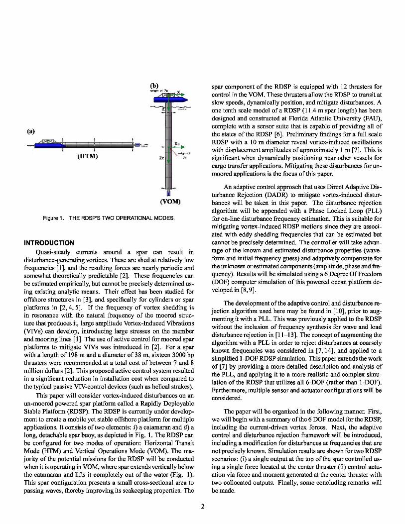
Figure 1. THE RDSP’S TWO OPERATIONAL MODES.
INTRODUCTION
Quasi-steady currents around a spar can result indisturbance-generating vortices. These are shed at relatively lowfrequencies [1], and the resulting forces are nearly periodic andsomewhat theoretically predictable [2]. These frequencies canbe estimated empirically, but cannot be precisely determined us-ing existing analytic means. Their effect has been studied foroffshore structures in [3], and specifically for cylinders or sparplatforms in [2, 4, 5]. If the frequency of vortex shedding isin resonance with the natural frequency of the moored struc-ture that produces it, large amplitude Vortex-Induced Vibrations(VIVs) can develop, introducing large stresses on the memberand mooring lines [1]. The use of active control for moored sparplatforms to mitigate VIVs was introduced in [2]. For a sparwith a length of 198 m and a diameter of 38 m, sixteen 3000 hpthrusters were recommended at a total cost of between 7 and 8million dollars [2]. This proposed active control system resultedin a significant reduction in installation cost when compared tothe typical passive VIV-control devices (such as helical strakes).
This paper will consider vortex-induced disturbances on anun-moored powered spar platform called a Rapidly DeployableStable Platform (RDSP). The RDSP is currently under develop-ment to create a mobile yet stable offshore platform for multipleapplications. It consists of two elements: i) a catamaran and ii) along, detachable spar buoy, as depicted in Fig. 1. The RDSP canbe configured for two modes of operation: Horizontal TransitMode (HTM) and Vertical Operations Mode (VOM). The ma-jority of the potential missions for the RDSP will be conductedwhen it is operating in VOM, where spar extends vertically belowthe catamaran and lifts it completely out of the water (Fig. 1).This spar configuration presents a small cross-sectional area topassing waves, thereby improving its seakeeping properties. The
spar component of the RDSP is equipped with 12 thrusters forcontrol in the VOM. These thrusters allow the RDSP to transit atslow speeds, dynamically position, and mitigate disturbances. Aone tenth scale model of a RDSP (11.4 m spar length) has beendesigned and constructed at Florida Atlantic University (FAU),complete with a sensor suite that is capable of providing all ofthe states of the RDSP [6]. Preliminary findings for a full scaleRDSP with a 10 m diameter reveal vortex-induced oscillationswith displacement amplitudes of approximately 1 m [7]. This issignificant when dynamically positioning near other vessels forcargo transfer applications. Mitigating these disturbances for un-moored applications is the focus of this paper.
An adaptive control approach that uses Direct Adaptive Dis-turbance Rejection (DADR) to mitigate vortex-induced distur-bances will be taken in this paper. The disturbance rejectionalgorithm will be appended with a Phase Locked Loop (PLL)for on-line disturbance frequency estimation. This is suitable formitigating vortex-induced RDSP motions since they are associ-ated with eddy shedding frequencies that can be estimated butcannot be precisely determined. The controller will take advan-tage of the known and estimated disturbance properties (wave-form and initial frequency guess) and adaptively compensate forthe unknown or estimated components (amplitude, phase and fre-quency). Results will be simulated using a 6 Degree Of Freedom(DOF) computer simulation of this powered ocean platform de-veloped in [8, 9].
The development of the adaptive control and disturbance re-jection algorithm used here may be found in [10], prior to aug-menting it with a PLL. This was previously applied to the RDSPwithout the inclusion of frequency synthesis for wave and loaddisturbance rejection in [11–13]. The concept of augmenting thealgorithm with a PLL in order to reject disturbances at coarselyknown frequencies was considered in [7,14], and applied to asimplified 1-DOF RDSP simulation. This paper extends the workof [7] by providing a more detailed description and analysis ofthe PLL, and applying it to a more realistic and complex simu-lation of the RDSP that utilizes all 6-DOF (rather than 1-DOF).Furthermore, multiple sensor and actuator configurations will beconsidered.
The paper will be organized in the following manner. First,we will begin with a summary of the 6 DOF model for the RDSP,including the current-driven vortex forces. Next, the adaptivecontrol and disturbance rejection framework will be introduced,including a modification for disturbances at frequencies that arenot precisely known. Simulation results are shown for two RDSPscenarios: (i) a single output at the top of the spar controlled us-ing a single force located at the center thruster (ii) control actu-ation via force and moment generated at the center thruster withtwo collocated outputs. Finally, some concluding remarks willbe made.
2
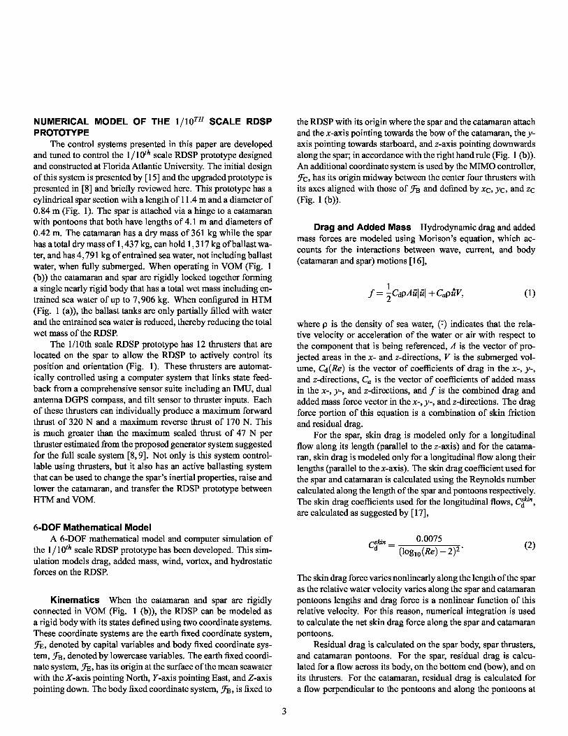
NUMERICAL MODEL OF THE 1 / 10TH SCALE RDSPPROTOTYPE
The control systems presented in this paper are developedand tuned to control the 1 / 10th scale RDSP prototype designedand constructed at Florida Atlantic University. The initial designof this system is presented by [15] and the upgraded prototype ispresented in [8] and briefly reviewed here. This prototype has acylindrical spar section with a length of 11 .4 m and a diameter of0 . 84 m (Fig. 1). The spar is attached via a hinge to a catamaranwith pontoons that both have lengths of 4 . 1 m and diameters of0 . 42 m. The catamaran has a dry mass of 361 kg while the sparhas a total dry mass of 1, 437 kg, can hold 1, 317 kg of ballast wa-ter, and has 4 , 791 kg of entrained sea water, not including ballastwater, when fully submerged. When operating in VOM (Fig. 1(b)) the catamaran and spar are rigidly locked together forminga single nearly rigid body that has a total wet mass including en-trained sea water of up to 7 , 906 kg. When configured in HTM(Fig. 1 (a)), the ballast tanks are only partially filled with waterand the entrained sea water is reduced, thereby reducing the totalwet mass of the RDSP.
The 1/10th scale RDSP prototype has 12 thrusters that arelocated on the spar to allow the RDSP to actively control itsposition and orientation (Fig. 1). These thrusters are automat-ically controlled using a computer system that links state feed-back from a comprehensive sensor suite including an IMU, dualantenna DGPS compass, and tilt sensor to thruster inputs. Eachof these thrusters can individually produce a maximum forwardthrust of 320 N and a maximum reverse thrust of 170 N. Thisis much greater than the maximum scaled thrust of 47 N perthruster estimated from the proposed generator system suggestedfor the full scale system [8, 9]. Not only is this system control-lable using thrusters, but it also has an active ballasting systemthat can be used to change the spar’s inertial properties, raise andlower the catamaran, and transfer the RDSP prototype betweenHTM and VOM.
6-DOF Mathematical ModelA 6-DOF mathematical model and computer simulation of
the 1 / 10th scale RDSP prototype has been developed. This sim-ulation models drag, added mass, wind, vortex, and hydrostaticforces on the RDSP.
Kinematics When the catamaran and spar are rigidlyconnected in VOM (Fig. 1 (b)), the RDSP can be modeled asa rigid body with its states defined using two coordinate systems.These coordinate systems are the earth fixed coordinate system,FE, denoted by capital variables and body fixed coordinate sys-tem, FB, denoted by lowercase variables. The earth fixed coordi-nate system, FE, has its origin at the surface of the mean seawaterwith the X-axis pointing North, Y-axis pointing East, and Z-axispointing down. The body fixed coordinate system, FB, is fixed to
the RDSP with its origin where the spar and the catamaran attachand the x-axis pointing towards the bow of the catamaran, the y-axis pointing towards starboard, and z-axis pointing downwardsalong the spar; in accordance with the right hand rule (Fig. 1 (b)).An additional coordinate system is used by the MIMO controller,FC, has its origin midway between the center four thrusters withits axes aligned with those of FB and defined by xC, yC, and zC
(Fig. 1 (b)).
Drag and Added Mass Hydrodynamic drag and addedmass forces are modeled using Morison’s equation, which ac-counts for the interactions between wave, current, and body(catamaran and spar) motions [16],
f = 2 CdρAu lu l + Caρ ˙uV, (1)
where p is the density of sea water, (7) indicates that the rela-tive velocity or acceleration of the water or air with respect tothe component that is being referenced, A is the vector of pro-jected areas in the x- and z-directions, V is the submerged vol-ume, Cd (Re) is the vector of coefficients of drag in the x-, y-,
and z-directions, Ca is the vector of coefficients of added massin the x-, y-, and z-directions, and f is the combined drag andadded mass force vector in the x-, y-, and z-directions. The dragforce portion of this equation is a combination of skin frictionand residual drag.
For the spar, skin drag is modeled only for a longitudinalflow along its length (parallel to the z-axis) and for the catama-ran, skin drag is modeled only for a longitudinal flow along theirlengths (parallel to the x-axis). The skin drag coefficient used forthe spar and catamaran is calculated using the Reynolds numbercalculated along the length of the spar and pontoons respectively.The skin drag coefficients used for the longitudinal flows, Cak"`,
are calculated as suggested by [17],
Cskin = 0 .0075
d (log 10 (Re) — 2 ) 2
. (2)
The skin drag force varies nonlinearly along the length of the sparas the relative water velocity varies along the spar and catamaranpontoons lengths and drag force is a nonlinear function of thisrelative velocity. For this reason, numerical integration is usedto calculate the net skin drag force along the spar and catamaranpontoons.
Residual drag is calculated on the spar body, spar thrusters,and catamaran pontoons. For the spar, residual drag is calcu-lated for a flow across its body, on the bottom end (bow), and onits thrusters. For the catamaran, residual drag is calculated fora flow perpendicular to the pontoons and along the pontoons at

their ends. Strip theory is used to calculate the forces perpen-dicular to the spar and pontoon buoys while a constant relativewater velocity is assumed for the ends of the spar and catama-ran pontoons. The residual drag coefficient for a flow across thespar (x-direction) is assumed to have a constant value of 1 . 0, assuggested by [18]. This same coefficient is used to calculate theresidual drag across the pontoons (z-direction) as both the pon-toons and the spar are approximately cylindrical. The coefficientor residual drag for a flow along the spar ( z-direction) at the sub-merged end is also assumed to have a value of 1.0, as suggestedby [18]. The same coefficient is used for the residual drag onthe ends of the pontoons. Residual drag forces on the submergedthrusters are calculated independent from the rest of the spar asthey are the only components of the RDSP that protrude out fromthe spar’s frame. The residual drag force on a thruster is cal-culated using separate but constant coefficients for flow paralleland perpendicular to the thrust axis. These coefficients are de-rived from tow tank tests, where the thrusters are towed facingparallel and perpendicular to the tow direction. The total dragcoefficients are derived from fitting curves to the data, which area function of velocity squared. These coefficients are used to cal-culate the drag forces for a flow parallel to each thruster and fora flow perpendicular to each thruster.
Added mass forces for both the spar and catamaran are mod-eled as an increase to the virtual mass and moment of inertia ofthe RDSP. This simplification can be made since waves are notconsidered for this application and therefore the local RDSP ac-celeration is the local relative acceleration. When operating inVOM, the virtual mass and virtual moment of inertia are calcu-lated for the RDSP in each direction using the actual mass andmoment of inertia (including entrained water), the added massand moment of inertia from the spar, and the added mass andmoment of inertia from the catamaran. The coefficient of addedmass for spar acceleration in the x-direction, perpendicular to thespar, is chosen as 1 and the coefficient of added mass for sparacceleration in the z-direction, parallel to the spar, is chosen as1 /n as suggested by [18]. These same coefficients are used fora flow perpendicular and parallel to the catamaran pontoons, re-spectively.
MODEL OF VORTEX-INDUCED DISTURBANCES ONTHE RDSP
Vortex-induced forces on spar platforms, such as the RDSP,develop when eddies are shed behind the cylindrical spar elementas it moves relative to the surrounding fluid (Fig. 2). This occurs
Figure 2. VORTEX-INDUCED MOTION ON A CIRCULAR CROSS-
SECTION.
when the relative velocity vector of the fluid has a componentthat acts parallel to the cross-section of the spar. During mostoperations, the RDSP will be dynamically positioned or mooredin a quasi-steady current. This induces disturbance-generatingvortices around the spar, beginning at very low relative water ve-locities. Vortices will also be shed at a nearly steady frequencyand amplitude when the RDSP is traveling in VOM at a nearlyconstant speed relative to the water velocity, such as when trans-ferring cargo from a slowly moving vessel. The frequency ofthese eddies can be estimated, but precise knowledge of the vor-tex shedding frequency cannot be determined analytically.
Eddy Shedding FrequencyFor a spar with a given diameter, the eddy shedding fre-
quency can be approximated using the relative water velocity [5].The frequency of shedding vortices from one side (see Fig. 2),w d = 2nfd = 2n
Td , is also the frequency of the oscillatory motion
induced in the transverse direction. This is typically estimatedempirically as a function of the Strouhal number with a relation-ship defined by [ 1 ] as
w d = 2n ^ , (3)
Thruster Forces The individual thruster forces andthrust rate are limited to match the maximum thrust to the powerplant suggested by [19] using Froude scaling. This limits themaximum thrust per engine to 47 N and the maximum thrust rateof change per engine to 37 .2 N/s for the motor configuration cho-sen for the 1 / 10th scale RDSP prototype with thrust values scaledfrom Thrustmaster Model TH 300N azimuthing thruster [20].
where S is the Strouhal number, D is the diameter, and V0 is therelative free stream velocity. The Strouhal number itself variesaccording to a poorly defined, nonlinear function of the currentvelocity. A relationship given by [1] shows that the Strouhalnumber ranges from 0 . 18 to 0 . 32. However, it can be approx-imated as a constant with a value of 0 .21 for cylindrical bodies,
4
as suggested by [5]. Thus, the eddy shedding frequency for theRDSP is modeled as a linear function of the cross flow velocity.For the full scale version, initial sizing estimates are in the rangeof 100 m length, 10 m diameter. Using these sizes as a referenceand relative water velocities from 0 . 1 to 2 . 0 m/s, eddies will beshed at frequencies from 0 . 013 to 0 .251 rad/s (period from 500to 24 s).
Because of the Strouhal number variability and other un-certainties (such as unknown or unmodeled dynamics or sensorresolution/calibration errors), a vortex shedding frequency esti-mate will likely vary by as much as 15 to 20% from its actualvalue. This crude estimate of the frequency provides a strongmotivation for using the PLL to better-estimate the disturbancefrequency in the loop, as proposed in [7].
Eddy Shedding ForceThe disturbances generated by vortices are nearly periodic
and somewhat theoretically predictable [2]. This eddy sheddingforce is calculated as [21 ]
FL (t) = AL sin ((A dt), (4)
where AL is the lateral eddy shedding force amplitude, (A d is theeddy shedding frequency that varies as a function of velocity ac-cording to (3), and t is the time in seconds. The amplitude of theforce is defined as [ 1 ]
AL = 12
CLLDp V02 , (5 )
where L is the length of the section of interest and CL is the co-efficient of lift estimated as 0 .28 [21].
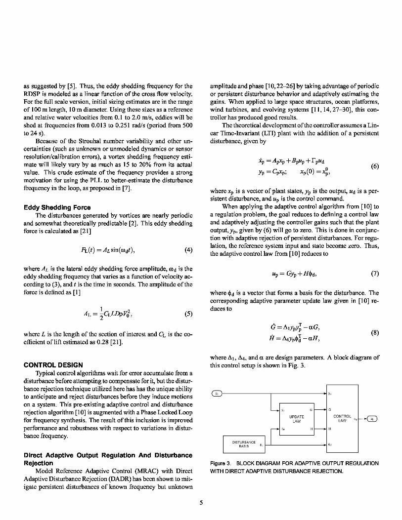
CONTROL DESIGNTypical control algorithms wait for error accumulate from a
disturbance before attempting to compensate for it, but the distur-bance rejection technique utilized here has has the unique abilityto anticipate and reject disturbances before they induce motionson a system. This pre-existing adaptive control and disturbancerejection algorithm [10] is augmented with a Phase Locked Loopfor frequency synthesis. The result of this inclusion is improvedperformance and robustness with respect to variations in distur-bance frequency.
amplitude and phase [ 10, 22–26] by taking advantage of periodicor persistent disturbance behavior and adaptively estimating thegains. When applied to large space structures, ocean platforms,wind turbines, and evolving systems [11, 14,27–30], this con-troller has produced good results.
The theoretical development of the controller assumes a Lin-ear Time-Invariant (LTI) plant with the addition of a persistentdisturbance, given by
xp = Apxp + Bpup + r pud
(6)0yp = Cpxp ; xp (0) = xp ,
where xp is a vector of plant states, yp is the output, ud is a per-sistent disturbance, and up is the control command.
When applying the adaptive control algorithm from [10] toa regulation problem, the goal reduces to defining a control lawand adaptively adjusting the controller gains such that the plantoutput, yp , given by (6) will go to zero. This is done in conjunc-tion with adaptive rejection of persistent disturbances. For regu-lation, the reference system input and state become zero. Thus,the adaptive control law from [10] reduces to
up = Gyp +H^d , (7)
where ^d is a vector that forms a basis for the disturbance. Thecorresponding adaptive parameter update law given in [10] re-duces to
G = A 1ypyTp — aG,
(8)H = A4yp^T
d — aH,
where A 1, A4, and a are design parameters. A block diagram ofthis control setup is shown in Fig. 3.
Direct Adaptive Output Regulation And DisturbanceRejection
Model Reference Adaptive Control (MRAC) with DirectAdaptive Disturbance Rejection (DADR) has been shown to mit-igate persistent disturbances of known frequency but unknown
Figure 3. BLOCK DIAGRAM FOR ADAPTIVE OUTPUT REGULATION
WITH DIRECT ADAPTIVE DISTURBANCE REJECTION.

Figure 4. PHASE LOCKED LOOP DETAILS.
Figure 5. CLOSED LOOP SYSTEM WITH MRAC/DADR AND A PLL.
Adaptation For Poorly Known FrequenciesWhen the frequency of a disturbance is not precisely known,
a complete basis can no longer be predefined for this disturbance.In this case, the performance of the DADR scheme is degraded[11,14]. Here, a Phase Locked Loop (PLL) is used to better-estimate the disturbance frequency. This allows the functions in^d within the DADR algorithm to more closely approximate thetrue basis. The focus of this modification is for the rejection ofa single vortex-induced disturbance, but the methodology is alsoapplicable for plants with multiple disturbances.
Phase Locked Loop A Phase Locked Loop (PLL) is acircuit that synchronizes the frequency and phase of an outputsignal to that of a given input signal [31, 32]. The PLL that isused here is shown in Fig. 4. Boxes highlight the three maincomponents that are common to all PLLs: synchronized oscil-lator, phase detector, and loop filter. In general, the role of the
the origin of the closed loop transfer function. Its purpose is tocancel with the extra pole generated by a disturbance input witha step change in the frequency rather than in the phase. Thismodification is made to improve the tracking performance.
Modified Control Framework The control frameworkset forth in [10] is modified to include an on-line frequency esti-mate that is provided by a PLL. A block diagram of the adaptivecontroller and DADR with the inclusion of a PLL is shown inFig. 5. The RDSP’s output goes through a bandpass pre-filterthat extracts the component of the signal within the frequencyrange of interest. This filtered output is used by the PLL to refinethe estimate of the disturbance frequency. The PLL frequencyestimate is lowpass filtered to eliminate any high frequency os-cillations. Finally, this frequency replaces the static frequencyguess in the DADR basis functions.
three main components may be described as follows. The phasedetector component of the PLL compares the input and the Syn-chronized Oscillator signals to determine an error signal that isproportional to the phase difference between the two. This er-ror feeds through the Loop Filter (LF) and drives the frequencyin the opposite direction. By continually updating the frequencyin the Synchronized Oscillator in this way, the signal is better-synchronized with the input signal in terms of phase and fre-quency. The PLL is designed to reduce the phase error until theoutput of the LF becomes stationary or “locked”, thus inspiringthe name “Phase Locked Loop”. When operating in this lockedstate, the frequency exiting the LF will match that of the inputsignal.
The particular formulation shown in Fig. 4 is a simplifiedversion of [33], and can be found in [34–36] for the case whereG (s) = G. Through linear analysis of the PLL, G (s) from [34,35]
is re-defined as G (s) = (s SKi) to provide an additional zero at
The bandpass pre-filter allows all of the signals outside therange of interest to be removed. Therefore, the input to the PLLprimarily contains the component of the plant’s output that is adirect result of the disturbance. If multiple disturbances are ex-pected, the framework may be adapted by including additionalsets of PLLs with corresponding filters. For example, n distur-bance frequency estimates would require n sets of bandpass fil-ters, PLLs, and low pass filters. Each bandpass pre-filter will beadjusted according to the expected frequency of the correspond-ing disturbance.
The filtered PLL frequency, ωLP is used in the DADRPLL
scheme rather than the unfiltered frequency, ωPLL, to reduce theoscillations in the DADR basis functions. This also reduces theeffect of the disturbance rejection portion of the controller at thebeginning of the simulation, giving the PLL time to lock onto thedesired frequency without having a large amount of interactionwith the DADR.
6
RESULTSFor each 6-DOF simulation, the six forward facing pro-
pellers provide a constant thrust of 300 N (50 N each) in thex-direction, inducing a surge velocity of approximately 0 .22 m/s.An initial surge velocity of 0 .22 m/s is given to the RDSP butthere is still a transient period before the disturbance frequencyconverges to a constant value (Fig. 7, Fig. 11). A basic PIDcontroller is used to minimize the RDSP’s yaw motion while theadaptive controller is configured to reduce the transverse oscilla-tory motions. As with the 1 DOF model [7,14], the control lawgiven by (7) with parameter update laws given by (8) is used inconjunction with a PLL. This controller implementation is shownin Fig. 5.
The gains in the update law (8) are chosen to be Δ 1 =200, 000 I2 , Δ4 = 20, 000 I2 , and α = 1 . 10-4. For the PLL, thegains are chosen to yield negative (stable) roots for s3 + as2 +aGs + aGKi = 0 by selecting G = 2 .5 . 10-4, Ki = 2 . 844 . 10-6 ,and a = 0 . 3.
The frequency guess for vortex disturbances was taken asωS = 0 . 25 rad/s. This is approximately 78% of the steady-statefrequency of vortex-induced disturbances (ω d ,: 0 . 32). Thus,1ω d - ω s 1 is selected such that it exceeds the expected frequencyestimation error for this application.
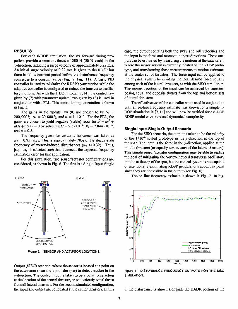
For this simulation, two sensor/actuator configurations areconsidered, as shown in Fig. 6. The first is a Single-Input-Single
Figure 6. SENSOR AND ACTUATOR LOCATIONS.
Output (SISO) scenario, where the sensor is located at a point onthe catamaran (near the top of the spar) to detect motion in they-direction. The control input is taken to be a point force actingat the location of the central thruster, or equivalently equal thrustfrom all lateral thrusters. For the second simulated configuration,the input and output are collocated at the center thrusters. In this
case, the output contains both the sway and roll velocities andthe input is the force and moment in these directions. These out-puts can be estimated by measuring the motions at the catamaran,where the sensor system is currently located on the RDSP proto-type, and transforming these measurements to motion estimatesat the center set of thrusters. The force input can be applied tothe physical system by dividing the total desired force equallyamong each of the lateral thrusters, as with the SISO simulation.The moment portion of the input can be achieved by superim-posing equal and opposite thrusts from the top and bottom setsof lateral thrusters.
The effectiveness of the controller when used in conjunctionwith an on-line frequency estimate was shown for a simple 1-DOF simulation in [7,14] and will now be verified for a 6-DOFRDSP model with increased dynamical complexity.
Single-Input-Single-Output ScenarioFor the SISO scenario, the output is taken to be the velocity
of the 1 / 10th scaled prototype in the y-direction at the top ofthe spar. The input is the force in the y-direction, applied at themiddle thrusters (or equally across each of the lateral thrusters).This simple sensor/actuator configuration may be able to realizethe goal of mitigating the vortex-induced transverse oscillatorymotion at the top of the spar, but the control system is not capableof intentionally eliminating RDSP pendulations about this pointsince they are not visible in the output (see Fig. 6).
The on-line frequency estimate is shown in Fig. 7. In Fig.
0.32
0.3
0.28
x
a 0.26
a0.24
disturbance frequencyPLL estimate
0.22
LP filtered PLL estimateInitial frequency estimate
0.2
0 200 400 600 800 1000 1200 1400 1600 1800 2000time, t [s]
Figure 7. DISTURBANCE FREQUENCY ESTIMATE FOR THE SISO
SIMULATION.
8, the disturbance is shown alongside the DADR portion of the

x 10−3
controller at the output (sensor) location. The standard devia-
s 2
$ 0
−2
−4
a
−8
0 200 400 600 800 1000 1200 1400 1600 1800 2000
time [s]
Figure 8. DISTURBANCE REJECTION EFFECTIVENESS FOR THE
SISO SIMULATION: FULL RUN TIME (LEFT) AND LAST 100 s (RIGHT).
tion of the acceleration at this point due to the vortex-induceddisturbance, given by CpFpud is 1.623 . 10-3 m/s2. When theDADR with a PLL is included, the STD of (Cpr pud +CpBpH^d)
becomes 1.056 . 10-3 m/s2 , and thus reduces the disturbance ap-pearing in the output by 35%.
The portion of the error not rejected a priori by the DADRscheme enters into the dynamical system (RDSP) and must thenbe mitigated by the output feedback term in the adaptive controllaw. The open loop STD of the velocity resulting from the vortexshedding for the last 1000 s of the simulation is 3.046 . 10-3 m/s.If the loop is closed with the MRAC (MRAC/DADR), this is re-duced to 2.626 . 10-3 m/s (1.300 . 10-4 m/s). The inclusion of thePLL with the MRAC/DADR algorithm yields a transverse veloc-ity error with a STD of 6.4 . 10-5 . Thus, the controller nearlyeliminates the velocity error, yp , at the top of the spar (as shownin Fig. 9). After removing the bias, the open and closed loopdisplacements are shown in Fig. 10 for the latter 1000 s of thesimulation. As with the velocity, the oscillations in position arealmost completely eliminated.
Multi-Input-Multi-Output Scenario
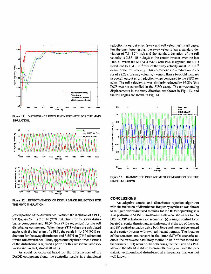
The output for the MIMO example is a vector containing thesway velocity in m/s and 10 times the roll velocity in rad/s. Thesway velocity output signal is selected as the input to the PLL,which provides an estimate for the frequency of both the forceand torque disturbances. Because the disturbance frequency it-self oscillates about an equilibrium, the PLL gains were selectedto provide a somewhat sluggish response. Thus, it takes 600 sfor the frequency estimate to initially approach the actual distur-bance frequency (as with the SISO case). This is shown in Fig.11.
1500 1550 1600 1650 1700 1750 1800 1850 1900 1950 2000time, t [s]
Figure 9. SWAY VELOCITY COMPARISON FOR THE SISO SIMULA-
TION.
0.015
0.01
0.005
E
s 0.g
−0.005
−0.01
−0.0151000 1100 1200 1300 1400 1500 1600 1700 1800 1900 2000
time, t [s]
Figure 10. TRANSVERSE DISPLACEMENT COMPARISON FOR THE
SISO SIMULATION.
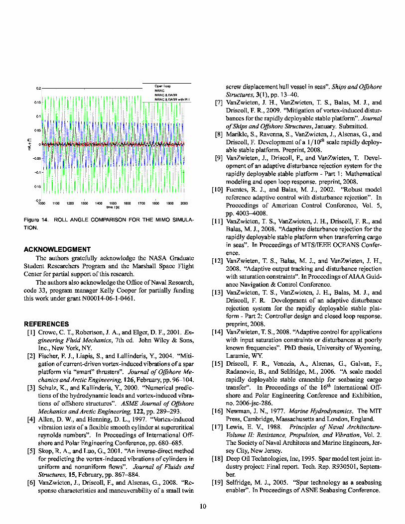
Fig. 12 shows the disturbance input (u d) plotted against theDADR component of the control command (H^ d) with and with-out the inclusion of a PLL. This is shown over only a portion ofthe simulation time in order to provide a closer look at these sig-nals. The standard deviation of the disturbance force and mo-ment over the last 1000 s of the simulation are 49.82 N and36.05 N-m, respectively. The disturbance rejection componentof the control command, Hid, does a much better job at oppos-ing the disturbance signal, ud, than in the SISO scenario. Thismay also be observed statistically by again considering the unre-
x 10−3
32.5
2 2
1.5 cf
^cf 1
1
1 0.5 $ 0[ W1 0 ^'
−1−0.5
−1 −2
−1.5
−3−2
− 2.5 −4
1900 1910 1920 1930 1940 1950 1960 1970 1980 1990 2000
time [s] −5
E 60
40
0 20
id 0
E −20
^ −40.9 −60
1500 1550 1600 1650 1700 1750 1800 1850 1900 1950 2000time, t [s]
rF%AI7
disturbance frequencyPLL estimateLP filtered PLL estimate
Initial frequency estimate
.0 200 400 600 800 1000 1200 1400 1600 1800 2000
time, t [s]
Figure 11. DISTURBANCE FREQUENCY ESTIMATE FOR THE MIMO
SIMULATION.
100
io_
50
0
2−50
−1001500 1550 1600 1650 1700 1750 1800 1850 1900 1950 2000
time, t [s]
reduction in output error (sway and roll velocities) in all cases.For the open loop results, the sway velocity has a standard de-viation of 7.1 . 10-3 m/s and the standard deviation of the rollvelocity is 3.88 . 10-2 deg/s at the center thruster over the last1000 s. When the MRAC/DADR with PLL is applied, the STDis reduced to 1.31 . 10-4 m/s for the sway velocity and 8.36.10- 3
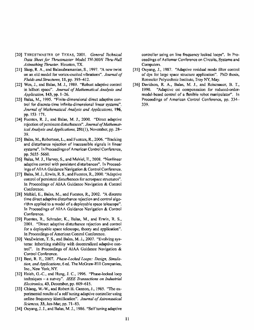
deg/s for the roll velocity. This corresponds to a reduction in er-ror of 98.2% for sway velocity, v – more than a two-fold increasein overall output error reduction when compared to the SISO re-sults. The roll velocity, p, was similarly reduced by 95.2% (thisDOF was not controlled in the SISO case). The correspondingdisplacements in the sway direction are shown in Fig. 13, andthe roll angles are shown in Fig. 14.
0.04
0.03
0.02E
0.012
`m
8 0w`o
.3 −0.01
−0.02
−0.03
−0.041000 1100 1200 1300 1400 1500 1600 1700 1800 1900 2000
time, t [s]
Figure 13. TRANSVERSE DISPLACEMENT COMPARISON FOR THE
MIMO SIMULATION.
0.32
0.3
0.28
am
g 0.26
W
W0.24
0.22
02
Figure 12. EFFECTIVENESS OF DISTURBANCE REJECTION FOR
THE MIMO SIMULATION.
j ected portion of the disturbance. Without the inclusion of a PLL,STD(ud + Hi$id) is 2.55 N (95% reduction) for the sway distur-bance component and 10.54 N-m (71% reduction) for the rolldisturbance component. When these STD values are calculatedagain with the inclusion of a PLL, the result is 1.47 N (97% re-duction) for the sway disturbance and 8.55 N-m (76% reduction)for the roll disturbance. Thus, approximately three times as muchof the disturbance is rejected a priori for this sensor/actuator sce-nario (and, in fact, almost all of it).
As could be expected based on the effectiveness of theDADR component alone, the controller results in a significant
CONCLUSIONS
An adaptive control and disturbance rejection algorithmwith the inclusion of disturbance frequency synthesis was shownto mitigate vortex-induced motions for the RDSP operating as aspar platform in VOM. Simulation results were shown for two 6-DOF RDSP actuator/sensor scenarios: (i) a single control forcelocated at center thruster and a single output at the top of the spar,and (ii) control actuation using both force and moment generatedat the center thruster with two collocated outputs. The locationof the actuators and sensors in the latter (MIMO) scenario re-duced the transverse oscillitory motion to half of that found forthe former (SISO) scenario. In both cases, the inclusion of a PLLallowed the MRAC/DADR to more effectively mitigate the per-sistent, vortex-induced disturbance at a frequency that was notwell known.
9
0.2
0.15
0.1
0.05
0e
−0.05
−0.1
−0.15
−0.21000 1100 1200 1300 1400 1500 1600 1700 1800 1900 2000
time, t [s]
Figure 14. ROLL ANGLE COMPARISON FOR THE MIMO SIMULA-
TION.
ACKNOWLEDGMENT
The authors gratefully acknowledge the NASA GraduateStudent Researchers Program and the Marshall Space FlightCenter for partial support of this research.
The authors also acknowledge the Office of Naval Research,code 33, program manager Kelly Cooper for partially fundingthis work under grant N00014-06-1-0461.
REFERENCES
[1]Crowe, C. T., Robertson, J. A., and Elger, D. F., 2001. En-gineering Fluid Mechanics, 7th ed. John Wiley & Sons,Inc., New York, NY.
[2] Fischer, F. J., Liapis, S., and Lallinderis, Y., 2004. “Miti-gation of current-driven vortex-induced vibrations of a sparplatform via “smart” thrusters”. Journal of Offshore Me-chanics and Arctic Engineering, 126, February, pp. 96–104.
[3] Schulz, K., and Kallinderis, Y., 2000. “Numerical predic-tions of the hydrodynamic loads and vortex-induced vibra-tions of offshore structures”. ASME Journal of OffshoreMechanics and Arctic Engineering, 122, pp. 289–293.
[4] Allen, D. W., and Henning, D. L., 1997. “Vortex-inducedvibration tests of a flexible smooth cylinder at supercriticalreynolds numbers”. In Proceedings of International Off-shore and Polar Engineering Conference, pp. 680–685.
[5] Skop, R. A., and Luo, G., 2001. “An inverse-direct methodfor predicting the vortex-induced vibrations of cylinders inuniform and nonuniform flows”. Journal of Fluids andStructures, 15, February, pp. 867–884.
[6] VanZwieten, J., Driscoll, F., and Alsenas, G., 2008. “Re-sponse characteristics and maneuverability of a small twin
screw displacement hull vessel in seas”. Ships and OffshoreStructures, 3(1), pp. 13–40.
[7] VanZwieten, J. H., VanZwieten, T. S., Balas, M. J., andDriscoll, F. R., 2009. “Mitigation of vortex-induced distur-bances for the rapidly deployable stable platform”. Journalof Ships and Offshore Structures, January. Submitted.
[8] Marikle, S., Ravenna, S., VanZwieten, J., Alsenas, G., andDriscoll, F. Development of a 1 / 10th scale rapidly deploy-able stable platform. Preprint, 2008.
[9] VanZwieten, J., Driscoll, F., and VanZwieten, T. Devel-opment of an adaptive disturbance rejection system for therapidly deployable stable platform - Part 1: Mathematicalmodeling and open loop response. preprint, 2008.
[10] Fuentes, R. J., and Balas, M. J., 2002. “Robust modelreference adaptive control with disturbance rejection”. InProceedings of American Control Conference, Vol. 5,pp. 4003–4008.
[11] VanZwieten, T. S., VanZwieten, J. H., Driscoll, F. R., andBalas, M. J., 2008. “Adaptive disturbance rejection for therapidly deployable stable platform when transferring cargoin seas”. In Proceedings of MTS/IEEE OCEANS Confer-ence.
[12] VanZwieten, T. S., Balas, M. J., and VanZwieten, J. H.,2008. “Adaptive output tracking and disturbance rejectionwith saturation constraints”. In Proceedings ofAIAA Guid-ance Navigation & Control Conference.
[13] VanZwieten, T. S., VanZwieten, J. H., Balas, M. J., andDriscoll, F. R. Development of an adaptive disturbancerejection system for the rapidly deployable stable plat-form - Part 2: Controller design and closed loop response.preprint, 2008.
[14] VanZwieten, T. S., 2008. “Adaptive control for applicationswith input saturation constraints or disturbances at poorlyknown frequencies”. PhD thesis, University of Wyoming,Laramie, WY.
[15] Driscoll, F. R., Venezia, A., Alsenas, G., Galvan, F.,Radanovic, B., and Selfridge, M., 2006. “A scale modelrapidly deployable stable craneship for seabasing cargotransfer”. In Proceedings of the 16 th International Off-shore and Polar Engineering Conference and Exhibition,no. 2006 -jsc-286.
[16] Newman, J. N., 1977. Marine Hydrodynamics. The MITPress, Cambridge, Massachusetts and London, England.
[17] Lewis, E. V., 1988. Principles of Naval Architecture-Volume II: Resistance, Propulsion, and Vibration, Vol. 2.The Society of Naval Architects and Marine Engineers, Jer-sey City, New Jersey.
[18] Deep Oil Technologies, Inc, 1995. Spar model test joint in-dustry project: Final report. Tech. Rep. R930501, Septem-ber.
[19] Selfridge, M. J., 2005. “Spar technology as a seabasingenabler”. In Proceedings of ASNE Seabasing Conference.
10
[20] THRUSTMASTER OF TEXAS, 2001. General TechnicalData Sheet for Thrustmaster Model TH- 300N Thru-HullAzimuthing Thruster. Houston, TX.
[21] Skop, R. A., and Balasubramanian, S., 1997. “A new twiston an old model for vortex-excited vibrations”. Journal ofFluids and Structures, 11, pp. 395–412.
[22] Wen, J., and Balas, M. J., 1989. “Robust adaptive controlin hilbert space”. Journal of Mathematical Analysis andApplication, 143, pp. 1–26.
[23] Balas, M., 1995. “Finite-dimensional direct adaptive con-trol for discrete-time infinite-dimensional linear systems”.Journal of Mathematical Analysis and Applications, 196,
pp. 153–171.[24] Fuentes, R. J., and Balas, M. J., 2000. “Direct adaptive
rejection of persistent disturbances”. Journal ofMathemat-ical Analysis and Applications, 251(1), November, pp. 28–39.
[25] Balas, M., Robertson, L., and Fuentes, R., 2006. “Trackingand disturbance rejection of inaccessible signals in linearsystems”. In Proceedings of American Control Conference,pp. 5655–5660.
[26] Balas, M. J., Harvey, S., and Mehiel, E., 2008. “Nonlinearadaptive control with persistent disturbances”. In Proceed-ings of AIAA Guidance Navigation & Control Conference.
[27] Balas, M. J., Erwin, R. S., and Fuentes, R., 2000. “Adaptivecontrol of persistent disturbances for aerospace structures”.In Proceedings of AIAA Guidance Navigation & ControlConference.
[28] Mehiel, E., Balas, M., and Fuentes, R., 2002. “A discretetime direct adaptive disturbance rejection and control algo-rithm applied to a model of a deployable space telescope”.In Proceedings of AIAA Guidance Navigation & ControlConference.
[29] Fuentes, R., Schrader, K., Balas, M., and Erwin, R. S.,2001. “Direct adaptive disturbance rejection and controlfor a deployable space telescope, theory and application”.In Proceedings of American Control Conference.
[30] VanZwieten, T. S., and Balas, M. J., 2007. “Evolving sys-tems: Inheriting stability with decentralized adaptive con-trol”. In Proceedings of AIAA Guidance Navigation &Control Conference.
[31] Best, R. E., 2007. Phase-Locked Loops: Design, Simula-tion, and Applications, 6 ed. The McGraw-Hill Companies,Inc., New York, NY.
[32] Hsieh, G.-C., and Hung, J. C., 1996. “Phase-locked looptechniques – a survey”. IEEE Transactions on IndustrialElectronics, 43, December, pp. 609–615.
[33] Chiang, W.-W., and Robert H. Cannon, J., 1985. “The ex-perimental results of a self tuning adaptive controller usingonline frequency identification”. Journal of AstronauticalSciences, 33, Jan-Mar, pp. 71–83.
[34] Ouyang, J. J., and Balas, M. J., 1986. “Self tuning adaptive
controller using on line frequency locked loops”. In Pro-ceedings of Asilomar Conference on Circuits, Systems andComputers.
[35] Ouyang, J., 1987. “Adaptive residual mode filter controlof dps for large space structure application”. PhD thesis,Rensseler Polytechnic Institute, Troy NY, May.
[36] Davidson, R. A., Balas, M. J., and Reisenauer, B. T.,1990. “Adaptive csi compensation for reduced-order-model-based control of a flexible robot manipulator”. InProceedings of American Control Conference, pp. 334–339.
11