
M08101.0 K800 Operator Manual - OPW
96
K800 ® Automated Fueling System Standard Version Operator’s Manual FSC Version 1.08L ©2002 OPW Fuel Management Systems Manual No. M08101.0 Rev. 3
Transcript of M08101.0 K800 Operator Manual - OPW

K800® Automated Fueling System Standard Version Operator’s Manual FSC Version 1.08L
©2002 OPW Fuel Management Systems Manual No. M08101.0 Rev. 3

OPW Fuel Management Systems - System and Replacement Parts Warranty Statement Effective September 1, 2002 System and Replacement Parts Warranty OPW Fuel Management Systems warrants that all OPW Tank Gauge and Petro Vend Fuel Control systems supplied by OPW Fuel Management Systems to the Original Purchaser will be free from defects in material and/or workmanship under normal use and service for a period of 12 months from the date of installation or 15 months from the date of shipment. Additionally, OPW Fuel Management Systems warrants that all upgrades and replacement parts (new and remanufactured) supplied by OPW Fuel Management Systems will be free from defects in material and workmanship under normal use and service for a period of 90 days from the date of installation or for the remainder of the system’s original warranty, whichever is greater, as set forth in the first sentence of this statement. The foregoing warranties will not extend to goods subjected to misuse, neglect, accident, or improper installation or maintenance or which have been altered or repaired by anyone other than OPW Fuel Management Systems or its authorized representative. The buyer’s acceptance of delivery of the goods constitutes acceptance of the foregoing warranties and remedies, and all conditions and limitations thereof. If a claim is made within the warranted time period that any equipment and/or remanufactured part is defective in material or workmanship under normal use and service, such equipment and/or remanufactured part shall be returned to OPW Fuel Management Systems, freight prepaid. If such equipment or remanufactured part is found by OPW Fuel Management Systems in its sole judgment, to be defective in material or workmanship under normal use and service, OPW Fuel Management Systems, shall, at its sole option, repair or replace such equipment and/or remanufactured part (excluding, in all instances, fuses, ink cartridges, batteries, other consumable items, etc.) The warranties, as set forth above, are made expressly in lieu of all other warranties, either expressed or implied, including, without limitation, warranties of merchantability and fitness for any particular purpose and of all other obligations or liabilities on OPW Fuel Management Systems part. Further, OPW Fuel Management Systems neither assumes, nor authorizes any other person to assume for it, any other liability in connection with the sale of the systems, or any new/replacement part that has been subject to any damage from any act of nature or any force majeure. The term “Original Purchaser” as used in these warranties shall be deemed to mean the authorized OPW Fuel Management Systems distributor to which the system or any new/replacement part was originally sold. These warranties may be assigned by the original purchaser to any of its customers who purchase any OPW Fuel Management Systems systems or new/replacement parts. The sole liability of OPW Fuel Management Systems, for any breach of warranty, shall be as set forth above. OPW Fuel Management Systems does not warrant against damage caused by accident, abuse, faulty or improper installation or operation. In no event shall manufacturer’s liability on any claim for damages arising out of the manufacture, sale, delivery or use of the goods exceed the original purchase price of the goods. In no event shall OPW Fuel Management Systems be liable for any direct, indirect, incidental or consequential damage or loss of product.
Contents
i
Table Of ContentsK800 SYSTEM OVERVIEW................................................................................................................................................... 1
HOW DOES IT WORK?.............................................................................................................................................................. 1SYSTEM FEATURES................................................................................................................................................................... 2
SPECIFICATIONS................................................................................................................................................................... 3
K800 FUEL ISLAND TERMINAL ........................................................................................................................................ 3
K800 FUEL SITE CONTROLLER......................................................................................................................................... 4
FUEL ISLAND TERMINAL (FIT) ......................................................................................................................................... 5
INSTALLATION.......................................................................................................................................................................... 5CARD OR KEY READER ............................................................................................................................................................ 5FIT DISPLAY............................................................................................................................................................................ 6FIT KEYPAD ............................................................................................................................................................................ 6
FUEL SITE CONTROLLER (FSC)........................................................................................................................................ 7
INSTALLATION.......................................................................................................................................................................... 7
PROGRAMMING WITH A TERMINAL OR COMPUTER ................................................................................................................... 7ATTACHING A JOURNAL PRINTER ............................................................................................................................................. 8USING A MODEM...................................................................................................................................................................... 8BATTERY BACKUP SYSTEM...................................................................................................................................................... 8
COMMAND ENTRY ................................................................................................................................................................... 9SETTING TIME, DATE AND PASSWORDS ................................................................................................................................... 9SITE CONFIGURATION OVERVIEW............................................................................................................................................. 9
Available Pump Parameters (see page Error! Bookmark not defined. to set up) ............................................................... 9Required Settings .............................................................................................................................................................. 10
CARD, KEY, AND ACCOUNT FILES.......................................................................................................................................... 10WHAT’S RECORDED FROM EACH TRANSACTION .................................................................................................................... 11CREATING REPORTS ............................................................................................................................................................... 12
POWERING UP THE SYSTEM ........................................................................................................................................... 13
COMMUNICATION................................................................................................................................................................... 13
FIRST STARTUP ...................................................................................................................................................................... 13LATER START-UPS.................................................................................................................................................................. 14
MAIN MENU OVERVIEW................................................................................................................................................... 15
USING THE SUB-MENUS ......................................................................................................................................................... 15SYSTEM SETUP....................................................................................................................................................................... 16
Site Configuration ............................................................................................................................................................. 16Tables ................................................................................................................................................................................ 16

K800 Automated Fueling System
ii 06/02/00
Card/Key/Account Files .................................................................................................................................................... 16Transactions...................................................................................................................................................................... 16Lock................................................................................................................................................................................... 16Quit (Modem Only) ........................................................................................................................................................... 16
HELP/ESCAPE ...................................................................................................................................................................... 17
8.0 SYSTEM SETUP MENU ................................................................................................................................................ 18
TIME ...................................................................................................................................................................................... 18
DATE...................................................................................................................................................................................... 19DAYLIGHT SAVINGS DATES.................................................................................................................................................... 19PASSWORD............................................................................................................................................................................. 19SITE NAME............................................................................................................................................................................. 20
SITE CONFIGURATION MENU......................................................................................................................................... 21
FUEL ISLAND TERMINALS....................................................................................................................................................... 21
PUMP PARAMETERS ............................................................................................................................................................... 21Position (POS) .................................................................................................................................................................. 24Pump Number (NBR) ........................................................................................................................................................ 24Status (STAT) .................................................................................................................................................................... 24Product Number (PRODUCT) .......................................................................................................................................... 24Supply Tank (TANK) ......................................................................................................................................................... 24Quantity Restriction (QNTY)............................................................................................................................................. 24Total Time For Fueling (TOTL)........................................................................................................................................ 25Max Time For Pump Handle (HNDL)............................................................................................................................... 25Missing Pulse Detect Time (MPD).................................................................................................................................... 25Pulser Divide Rate (DIVD) ............................................................................................................................................... 25Pump Handle Monitor....................................................................................................................................................... 25Pump Sentry (SENT) ......................................................................................................................................................... 25
TABLES MENU...................................................................................................................................................................... 28
PRODUCT NAMES AND PRICES............................................................................................................................................... 28
PRODUCT RESTRICTIONS ........................................................................................................................................................ 29QUANTITY RESTRICTIONS ...................................................................................................................................................... 30ACCESS TIME RESTRICTIONS.................................................................................................................................................. 31FIT MESSAGES ...................................................................................................................................................................... 32
CARD/KEY ACCOUNT FILES MENU
.............................................................................................................................. 35
UNDERSTANDING THE K800 USER FILE ................................................................................................................................. 35Cardless Entry................................................................................................................................................................... 35Number.............................................................................................................................................................................. 35Type................................................................................................................................................................................... 36
SHOWING USER FILE(S) ......................................................................................................................................................... 37EDITING USER FILE(S)............................................................................................................................................................ 38
Card/Key Type .................................................................................................................................................................. 39Validation Status ............................................................................................................................................................... 39

Contents
iii
Mileage Flag ..................................................................................................................................................................... 39Keyboard Entry Message .................................................................................................................................................. 39
Quantity Restriction Level................................................................................................................................................. 40
Product Restriction Level.................................................................................................................................................. 40
Access Time Restriction Level ......................................................................................................................................... 40
Max Transactions Per Day ............................................................................................................................................... 40Card/Key Issue Number .................................................................................................................................................... 40PIN .................................................................................................................................................................................... 41Invalid PIN Entries ........................................................................................................................................................... 41Account Number................................................................................................................................................................ 41
SHOWING ACCOUNT FILE(S) .................................................................................................................................................. 43EDITING ACCOUNT FILES ....................................................................................................................................................... 43
Validation Status ............................................................................................................................................................... 44Quantity Restriction .......................................................................................................................................................... 44Product Restriction ........................................................................................................................................................... 44Access Time Restriction .................................................................................................................................................... 44Name ................................................................................................................................................................................. 44
TRANSACTIONS MENU...................................................................................................................................................... 45
NUMBER ................................................................................................................................................................................ 45RECALL.................................................................................................................................................................................. 45POLL ...................................................................................................................................................................................... 46ERASE .................................................................................................................................................................................... 46
REPORTS MENU
................................................................................................................................................................... 47
SYSTEM INFORMATION REPORT ............................................................................................................................................ 48PUMP TOTALS REPORT........................................................................................................................................................... 49PRODUCT TOTALS REPORT..................................................................................................................................................... 50INVENTORY REPORT............................................................................................................................................................... 51PRINTING A REPORT ............................................................................................................................................................... 52REPORT PACKAGE.................................................................................................................................................................. 54
APPENDIX A - K800 POLL DATA........................................................................................................................................ 58
POLL DATA FORMAT .............................................................................................................................................................. 58POLL DATA CHECKSUM.......................................................................................................................................................... 59
APPENDIX B - MODEMS..................................................................................................................................................... 60
INTRODUCTION....................................................................................................................................................................... 60HOST MODEM CONFIGURATION ............................................................................................................................................. 60SITE MODE CONFIGURATION.................................................................................................................................................. 61PASSWORD............................................................................................................................................................................. 61CALLING A K800 SITE ........................................................................................................................................................... 61
APPENDIX C – EPROM REPLACEMENT........................................................................................................................ 63
OVERVIEW ............................................................................................................................................................................. 63
FSC PV245 OR PV249 EPROMS.......................................................................................................................................... 63FIT PV247 EPROMS ............................................................................................................................................................ 64
APPENDIX D - CHIPKEY PROGRAMMING ................................................................................................................... 65
OVERVIEW ............................................................................................................................................................................. 65

K800 Automated Fueling System
iv 06/02/00
ODOMETER REASONABILITY .................................................................................................................................................. 65MILEAGE VALUES .................................................................................................................................................................. 66SERVICE WARNINGS............................................................................................................................................................... 67INCORRECT ENTRY RESPONSES.............................................................................................................................................. 67
Method 0 ........................................................................................................................................................................... 67Method 1 ........................................................................................................................................................................... 67Method 4 ........................................................................................................................................................................... 67
ENCODING PROCEDURE.......................................................................................................................................................... 68
APPENDIX E – TROUBLESHOOTING
............................................................................................................................. 71
FIT TEST.............................................................................................................................................................................. 71STATUS LIGHT ERROR CODES ................................................................................................................................................ 72"PUMP IN USE" MESSAGE .................................................................................................................................................. 73"NOT AVAILABLE - REENTER" MESSAGE ...................................................................................................................... 73"OUT OF SERVICE REENTER" MESSAGE ........................................................................................................................ 73TROUBLESHOOTING FLOWCHARTS ......................................................................................................................................... 74
Communication Failure Between FSC and Terminal ....................................................................................................... 75Display on FIT is Blank .................................................................................................................................................... 76Incorrect Readings (Optical & ChipKey Readers)............................................................................................................ 77Modem Does Not Answer ................................................................................................................................................. 78Printer Not Printing Transactions .................................................................................................................................... 79"Pump Handle Re-Enter" Message................................................................................................................................... 80"System OFF" Message..................................................................................................................................................... 81
TRANSFORMER VOLTAGES ..................................................................................................................................................... 82
NOTES:.......................................................................................................................ERROR! BOOKMARK NOT DEFINED.
APPENDIX F............................................................................................................................................................................ 83
FILE CONVERTER FOR K800 PHOENIX ............................................................................................................................ 83
DESCRIPTION.......................................................................................................................................................................... 83
ASCII .................................................................................................................................................................................... 83
APPENDIX G.......................................................................................................................................................................... 85
QUICK-USE OPERATIONAL FLOWCHARTS ................................................................................................................ 85
CLEARING A TRANSACTION.................................................................................................................................................... 85ENTERING FILES AND ACCOUNTS ........................................................................................................................................... 86PROGRAMMING PUMP INFORMATION ..................................................................................................................................... 87RUNNING A REPORT PACKAGE ............................................................................................................................................... 88
INDEX ...................................................................................................................................................................................... 89

Programming
1
Part I - IntroductionK800 System Overview
How Does It Work?
The K800 Automated Fueling System is designed to manage a small to mid-size fueling operation.Many features of our larger systems are incorporated into the K800.
The K800 is simple to install and program. Its backlit LCD display prompts your customersthrough the entire fueling process, making it fast and easy. Despite its ease of use, the K800 isextremely versatile. The system provides for 24-hour unattended fueling.
A K800 system consists of one to four Fuel Island Terminals (FITs) mounted at the fueling island,and one Fuel Site Controller (FSC).
The FIT is the device used by the customer, and houses the reader device (cards or ChipKeys),keypad, display and emergency stop button. Four hoses per FIT can be controlled simultaneously.Up to 10,000 cards and 1,800 transactions can be held in memory. This allows smaller operationsto expand, without having to invest in more equipment.
ChipKeys can be used with or in place of cards. Rugged, tamper-proof, they fit on a driver's keyring, making them hard to misplace. The FITs "talk" to the FSC through Petro Net, a twisted pairof wires.
The FSC is an indoor computer, containing battery- backed memory for card/key and account filesand transactions. The FSC provides the interface to the printer, the programming terminal orcomputer, and a modem option. Security is provided with changeable, user-selected PINs. Anautomatic user lockout detects bad PIN entries, and various limitations based on product volume ordollar amount can also be programmed.
A "Features Checklist" for your K800 appears on the next page. All are described in various partsof the manual.

K800 Automated Fueling System
2 06/02/00
System Features
• Twenty-four hour fueling
• Optical Card, Magnetic Card or ChipKey compatible
• One to four simultaneous hoses per FIT
• Manual bypass switch for each hose
• Memory for up to 10,000 cards and 1800 transaction records
• System can lock out any card or key
• PIN number entry with lockout
• Four levels of time access
• Product or quantity restrictions
• Odometer or miscellaneous entries accepted
• Adjustable pump timeouts
• Pump handle monitor for safety
• Self-diagnostics
• Journal printer uses plain paper
• Versatile Report Package standard
• Inventory, Pump and Product Total reports
• Menu-driven programming
• Three serial COMM ports
• Battery-backup
• User-programmable prompts on FIT
• Durable alloy keypad
• Rugged door overlay
• Built-in pulser power supply
• Simple two-wire Petro Net communication
• Built-in pump control relays
• Pedestal mount for easy access

Programming
3
Specifications
K800 FUEL ISLAND TERMINAL
Power Requirements Standard Optional
120 VAC, 60 Hz, 100W220 - 240 VAC, 50 Hz
Dimensions 12" H x 13" W x 10" D(30.5cm H x 33cm W x 25.4cm D)
Operating Temperature Range -40EF to 110EF(-40EC to 43EC)
Reader Standard Magnetic Stripe Optional Optical Card Optional ChipKey
10,000 cards, 1800 transactions10,000 cards, 1800 transactions10,000 keys, 1800 transactions
Pump Control 3/4 HP, 120/240 VAC
PulserCompatibilityPower SupplyRateSpeed
Duty Cycle:
Contact / 12 VDC Electronic12 VDC, 40 mA max per pulser1:1 to 1000:1, in one-pulse incrementsMECHANICAL: 6,000 pulses per minuteELECTRONIC: 100,000 pulses per minute50%
Maximum Petro Net Wiring Extension 5000 ft(1420 m)

K800 Automated Fueling System
4 06/02/00
K800 FUEL SITE CONTROLLER
Dimensions 2" H x 9" W x 11" D(5cm H x 23cm W 28cm D)
Power Requirements Standard Optional
120 VAC, 60 Hz, 30W220 - 240 VAC, 50 Hz
Ports Petro-Net Printer Terminal Modem
RS-485RS-232RS-232 (WYSE 50 emulation)212A/224A
Operating Temperature Range FSC Peripherals
20EF to 100EF (-7EC to 38EC)40EF to 85EF (5EC to 29EC)
Port Communication Speeds Petro Net (RS-485) Printer (Epson/serial) Terminal (RS-232) Modem (212A/224A)
9600 baud, maximum 5,000 feet2400 baud, maximum 6 feet9600 baud, maximum 50 feet1200/2400 baud, maximum 50 feet

Programming
5
Fuel Island Terminal (FIT)
Installation
Refer to the K800 Installation Manual supplied with the system for complete installation details.
Up to four FITs can be installed per FSC. The FIT greets your customers, and prompts them through thefueling process. A keypad lets customers enter data like PIN numbers, or account numbers for cardless entry.
FITs communicate with the Fuel Site Controller via Petro-Net, a twisted-pair cable inside a steel conduit. TheFSC is described inm its own section of this book.
The FIT(s) (and all K800 components) must be installed as described in the K800 Installation Manual. TheInstallation Manual also contains DIP switch information and LED functions.
Card or Key Reader
Access the K800 with a card, a ChipKey, or a keypad entry. If a card reader is installed, one or two of thefollowing are in the FIT:
� ABA standard track II magnetic stripe cards� Optically-read cards, punch-encoded� ChipKeys� Cardless Access: a keypad data entry is substituted for inserting a card or key*� Dual Access: files are assigned to both the driver and the vehicle; restrictions for both files must be satisfied in
order to fuel� Standard Dual Access: the second access number must be read from a card or key
* A DUAL-cardless model is available as special order. This method requires you enter both accessnumbers from the keypad. Contact Petro Vend for more information.

K800 Automated Fueling System
6 06/02/00
FIT DisplayThe LCD display is visible even in sunlight and is backlit for night viewing. The display shows messages oftwo lines, each line containing up to 16 characters.
FIT Keypad[1] - [0] - Use the ten number keys to enter PIN numbers, pump numbers, odometer entries andmiscellaneous information. As a memory aid, the data keys are labeled as on a telephone. For example, acustomer with the PIN "3733" could remember this as "FRED" by associating each number with a letter fromthe data key.
[ENTER/YES] - This key has two functions: as an ENTER key, it sends your keyboard entry to the system.Its other function is to answer YES to a YES/NO? prompt.
[CLEAR/NO] - This key, also dual-purpose, either clears a displayed entry or answers NO to a YES/NO?prompt.
[EMERG STOP] - Press the Emergency Stop button to immediately stop the fuel pumps. The systemreturns to normal operation when the next card or key is inserted.
WARNING!The emergency stop switch on the FIT may not satisfy the National Electrical Coderequirements, Article 514-5 of NFPA 70 specifies that emergency controls shall be locatedmore than 20 feet but less than 100 feet from the dispensers. The emergency controlsmust shut off all power to all dispensing equipment at the station. This is subject toapproval by the authority having jurisdiction.
CAUTION!Do NOT use high-pressure cleaning equipment to clean the FIT! Wipe the unit down with a clothmoistened with regular household cleaner

Programming
7
Fuel Site Controller (FSC)
Installation Refer to the K800 Installation Manual for complete FSC installation instructions. The FSC must beinstalled indoors! This small desktop unit houses the memory for your card and account records.The FSC also does the following:
� Manages the operations of the FITs
� Communicates with your terminal or PC
� Sends output to the printer and optional modem.
The FSC must be connected to one of the FITs using twisted pair wiring and rigid steel conduit.Refer to the Installation Manual. The Installation Manual also contains DIP switch setup and LEDinformation
Programming with a Terminal or ComputerYou program the K800 with a terminal, or a PC running emulation software. The system can beprogrammed locally (with the terminal attached directly to the FSC) or over phone lines with amodem.
When connected to a PC, the PC must run a "terminal emulation" program to simulate theoperations of an ASCII terminal.
CAUTION!The plug-in transformers for the Petro VendSystem2 FSC and the K800 FSC are NOTinterchangeable! Using the wrong transformerin your FSC will damage the FSC.

K800 Automated Fueling System
8 06/02/00
A K800 version of the Petro Vend Phoenix software package is also available. Phoenix isdesigned especially for interfacing the K800 to a personal computer.
Along with terminal emulation, Phoenix provides all the know-how you need to manage K800data quickly and easily. No special computer training or experience is needed.
Additional computer-formatted commands allow the K800's data to be polled, backed up, restoredor even created by another computer.
Attaching a Journal PrinterConnect a journal printer to the FSC PTR port. The printer is required to use the Report Package(described in an appendix). The standard journal printer is 115VAC, and draws 120W.
Using a ModemFor remote operation, the FSC MODEM port connects to an optional modem to provide you withcontrol from a remote terminal or computer over standard telephone lines. The standard modemuses 115VAC and draws 20 watts.
Modems are discussed in an appendix.
Battery Backup SystemAn internal battery maintains FSC data even if power is removed from the unit. Press theBATTERY button on the front of the FSC. If the battery is good, an LED on the front panellights.
Test the battery at least once per month. If the battery does not pass the test, contact your PetroVend distributor for a replacement.

Programming
9
Functional Overview
Command EntryAll the commands to setup the K800 system and to generate reports are listed on menus: nocommands need be memorized. Help screens are available at each menu.
Setting Time, Date and PasswordsYou must set the internal clock of the K800 with the current time and date. You may also programdates for daylights savings changes.
To program a password for modem operation, see the modem appendix.
Site Configuration OverviewYou can set the K800 for keyed or keyless/cardless access.
Available Pump Parameters� Pump Number
� Pump Status
� Product Name
� Tank Number
� Quantity Restriction
� Total Time for Fueling
� Max Time for Pump Handle
� Max Time for First Pulse
� Max Time for MPD
� Pulser Divide Rate
� Pump Handle Monitor
� Pump Sentry

K800 Automated Fueling System
10 06/02/00
Required SettingsThe following data tables must be programmed for the K800.
� Product names and prices
� Product restrictions
� Quantity restrictions
� Access time restrictions
Card, Key, and Account FilesDefine for individuals or vehicles. Each user file contains the following information:
� Card/key number
� Card/key type
� Validation status
� Mileage flag
� Keyboard entry message
� Quantity restrictions per transaction
� Product restriction
� Access time restriction
� Maximum number of transactions per day
� Card/key issue number
� Personal identification number ("PIN")
� Maximum number of bad PIN entries
� Account number
Programming
11
User files can also be assigned to accounts, with each account containing the following information:
• Account number
• Validation status
• Quantity restrictions per transaction
• Product restriction
• Access time restriction
• Account name
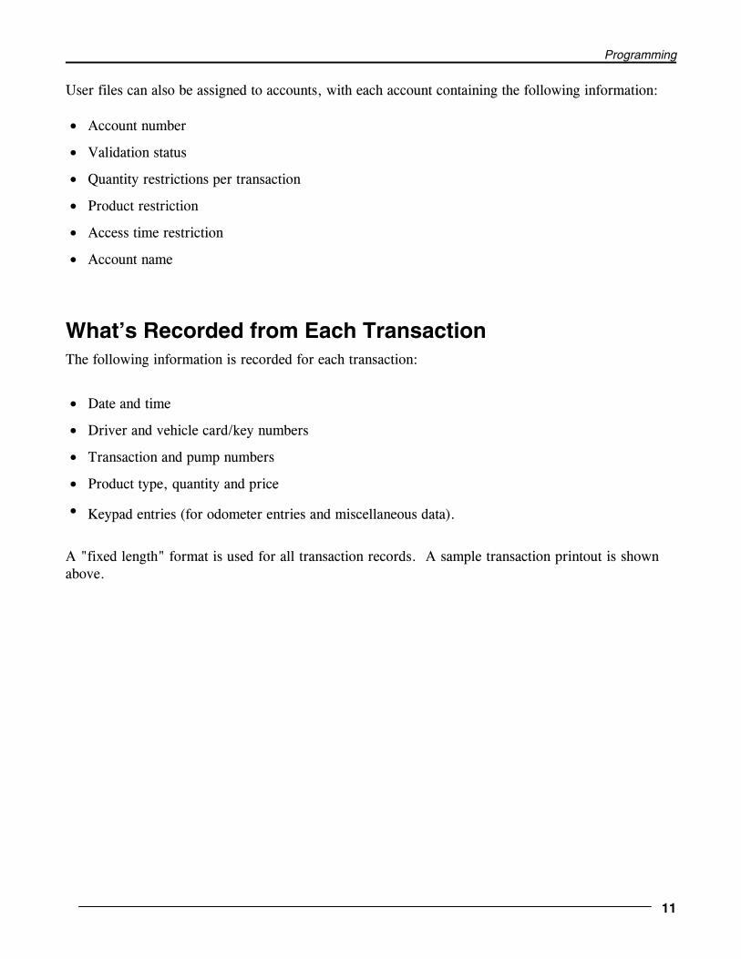
What’s Recorded from Each TransactionThe following information is recorded for each transaction:
• Date and time
• Driver and vehicle card/key numbers
• Transaction and pump numbers
• Product type, quantity and price
• Keypad entries (for odometer entries and miscellaneous data).
A "fixed length" format is used for all transaction records. A sample transaction printout is shownabove.

K800 Automated Fueling System
12 06/02/00
Transactions can end in various ways. Possible Transaction TYPES (shown in one column of theprintout) are:
Type # Description
0 Normal
1 Total Time Expired
2 Handle Timer Expired
3 First Pulse Timer Expired
4 Missing Pulse Timer Expired
5 Emergency Stop Pressed
6 Quantity Limit Exceeded
7 Communication Error
8 Power Failure
Creating ReportsThe K800 can generate reports on its status, pump totals and product totals. An internal reportpackage is available to process transaction data.
The internal report package processes quantity and price totals by account or individual. Data canbe easily transferred in compressed format to another computer for processing.

Programming
13
Powering Up the System
CommunicationTo communicate with the K800, you must configure your terminal or PC terminal emulation software in thefollowing manner:
Emulation WYSE 50
Display Lines 24
Scrolling Jump
COMM Mode Full Duplex (FDX)
Baud Rate 9600
Data/Stop bits 7/1
Parity EVEN
Protocol RS-232C
The above are default values for the Link terminal (available from Petro Vend) and do not need to be changed. Refer to your particular terminal owner's manual to check or change its configuration.
If you are using a PC, it must run a "terminal emulation" software in order to communicate with the K800. Most emulation packages can be set to communicate with the K800.
First StartupIf you have not yet started your system, do the following:
1. Power up the FIT(s) and the peripheral devices.
2. Remove the FSC cover and plug in the battery.
3. Plug the power transformer into a convenient AC outlet.
4. Press and hold the FSC TEST button. While holding the button, insert the power cable into its socket onthe FSC.

K800 Automated Fueling System
14 06/02/00
5. Hold the TEST button until the STATUS light flashes continuously.
6. If the STATUS light flashes intermittently, it is signaling an error code. See Page 72 for a code list.
7. Replace the FSC cover.
After the Status light begins to flash continuously, the MAIN MENU should appear on the display and theheader should print on the printer.
Later Start-upsThere are three types of system start-up, Cold, Warm, and Cool.
COLD START. The K800 is cold started only when there are no data stored in the FSC.
WARM START. The K800 is warm started after the AC power supply has been removed or disrupted or ifthe RESET button has been pressed. As long as the FSC battery is functional, no data are lost.
COOL START. A cool start occurs when the program EPROM in the FSC is replaced. The system setup,site configuration and table data must be re-entered.
In a cool start, all card, key and account data remain intact, as long as the FSC battery is functional.
Programming
15
Part II - ProgrammingMain Menu Overview
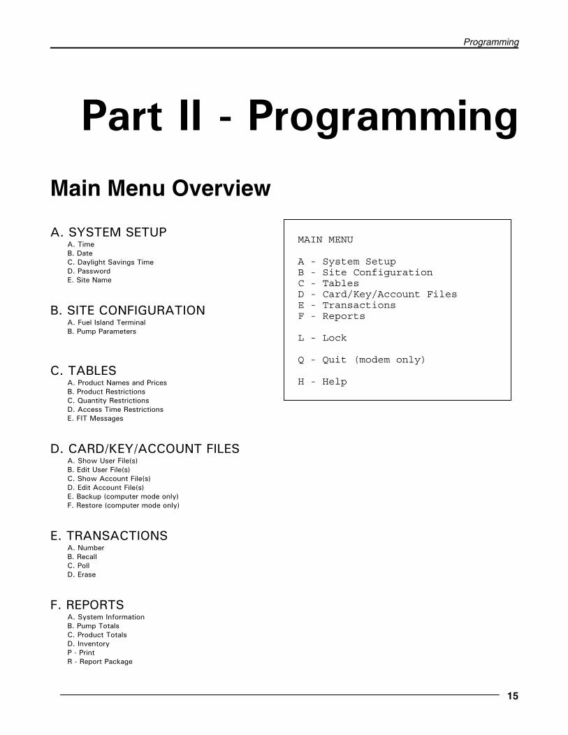
A. SYSTEM SETUPA. TimeB. DateC. Daylight Savings TimeD. PasswordE. Site Name
B. SITE CONFIGURATIONA. Fuel Island TerminalB. Pump Parameters
C. TABLESA. Product Names and PricesB. Product RestrictionsC. Quantity RestrictionsD. Access Time RestrictionsE. FIT Messages
D. CARD/KEY/ACCOUNT FILESA. Show User File(s)B. Edit User File(s)C. Show Account File(s)D. Edit Account File(s)E. Backup (computer mode only)F. Restore (computer mode only)
E. TRANSACTIONSA. NumberB. RecallC. PollD. Erase
F. REPORTSA. System InformationB. Pump TotalsC. Product TotalsD. InventoryP - PrintR - Report Package
MAIN MENU
A - System SetupB - Site ConfigurationC - TablesD - Card/Key/Account FilesE - TransactionsF - Reports
L - Lock
Q - Quit (modem only)
H - Help

K800 Automated Fueling System
16 06/05/00
Using the Sub-MenusAll sub-menus are accessed from a Main menu. Call the Main menu by pressing the [ENTER] key (possiblyseveral times) from any point.
When first using the system the `Enter Password' message displays. The initial password is the six-digitsystem serial number. The serial number is on the data sheet supplied with the system, and on a label affixedto the bottom of the FSC. The "W" in the serial number is not part of the password. This password is alsoused if you are accessing the system remotely via modem! Select a function from a menu by pressing the letterkey and then [ENTER]. Each Main Menu selection is described below.
System SetupUse System Setup to set time of day, date, daylight savings time dates, passwords and to assign a sitename to your K800.
Site ConfigurationUse this menu to display FIT parameters like operational status, reader type and software version number.Also displays and lets you change individual pump parameters.
TablesThe Tables sub-menu lets you specify product names and prices, product restrictions, quantity restrictions,access time restrictions, and FIT messages.
Card/Key/Account FilesUse this sub-menu to show or edit user files, to show or edit account files, and to back up or restore systemconfiguration data (while in computer mode).
TransactionsThis sub-menu displays the total number of transactions, lets you display transactions one at a time, transmittransactions (in a "compressed" computer format), or erase transactions from the K800 data base.
LockThis selection blanks the screen and then "locks" the terminal to prevent unauthorized access. After theterminal is locked, the password must be entered to gain access.
Quit (Modem Only)When the K800's programming terminal or computer is located at a remote site, modems are used forcommunication. Selecting Quit from the Main menu disconnects the K800 from the modem.
.

Programming
17
Help/ESCAPE“Help” screens are available for the MAIN MENU and all the submenus. These screens display informationabout the current menu.
Press ([Esc]) to return to the Main menu. If you press [Esc] in the middle of a data entry sequence, thecommand is aborted and the data not accepted.
K800 Automated Fueling System
18 06/02/00
8.0 System Setup Menu
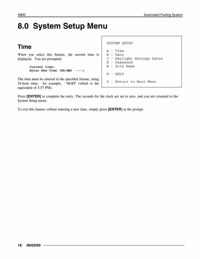
TimeWhen you select this feature, the current time isdisplayed. You are prompted:
Current time:Enter New Time (HH:MM) ---->
The time must be entered in the specified format, using24-hour time; for example, `15:57' (which is theequivalent of 3:57 PM).
Press [ENTER] to complete the entry. The seconds for the clock are set to zero, and you are returned to theSystem Setup menu.
To exit this feature without entering a new time, simply press [ENTER] at the prompt.
SYSTEM SETUP
A - TimeB - DateC - Daylight Savings DatesD - PasswordE - Site Name
H - HELP
X - Return to Main Menu
Programming
19
DateWhen you select this feature, the current date is displayed. You are prompted:
Current date:Enter New Date(MMM DD, YYYY) ---->
The date must be entered in the specified format; for example, `JAN 02, 1996'. Be sure to enter twodigits for the day and four digits for the year.
Press the [ENTER] key to complete the entry and to return to the System Setup menu. To exit this featurewithout entering a new date, simply press [ENTER] at the prompt.
Daylight Savings DatesThis feature lets you choose the dates on which the internal clock will automatically go forward and backwardan hour. You are prompted to enter new dates. If you do not want to change a date, simply press [ENTER] atthe prompt. Once past programmed date, it is automatically deleted and replaced with question marks.
PasswordA password must be entered in order to gain access tothe K800. The initial password is the six-digit systemserial number. The serial number is on the data sheetsupplied with the system, and on a label affixed to thebottom of the FSC. The "W" in the serial number is notpart of the password.
Use the `PASSWORD' command to change thepassword. The new password can be numbers and/orletters; the password is "case-sensitive;" that is, upper and lower case letters are distinguished. Thepassword must be exactly six characters in length.
When you enter the password, you are prompted a second time to ensure a correct entry. Unless the samepassword is entered both times, the new password is rejected.
IMPORTANT!Be sure to write down and safely store thenew password. It can not be recalled fromthe system. If you forget the password,contact Petro Vend.

K800 Automated Fueling System
20 06/02/00
Site NameThe site name appears at the top of every page of transactions and on each page of the reports for the ReportPackage. The current name is displayed. The maximum length of the site name is determined by yoursoftware version:
Version 1.08i: 39 characters maxVersion 1.09A: 40 characters max
Enter a new site name (numbers or letters), or simply press [ENTER] to leave the site name unchanged.

Programming
21
Site Configuration Menu
Fuel Island Terminals
When this feature is selected, the following information is displayed for each FIT:
� Operational status (running or down)
� Type of reader (magnetic card, optical card, or Chipkey)
� Software version number and release date
Press the [ENTER] key to exit to the SITE CONFIGURATION MENU.
Pump Parameters
Up to four pumps can be connected to each K800 FIT. A K800 system can have up to four FITs, for a total of16 pumps. The FIT number is determined by DIP switches on the FIT board.
SITE CONFIGURATION
A - Fuel Island TerminalsB - Pump Parameters
H - HELP
X - Return to Main Menu

K800 Automated Fueling System
22 06/02/00
The pumps are identified by the terminal position to which they are connected:
FIT # Pump Positions
1 1 - 4
2 5 - 8
3 9 - 12
4 13 - 16
After you select Pump Parameters the current configuration appears. A typical configuration is shown on thenext page. You are also prompted:
Do you wish to change? (Y/N/X)
Enter `N' (for no), `Y' (for yes) or `X' (to exit). If you answer yes, you are prompted to enter a pumpposition. After entering a position number, you will specify data for each pump parameter.
These parameters are explained in the following paragraphs; the label inside parenthesis is what appears on thescreen. Press [ENTER] at a prompt to keep the current data.

Programming
23
PUMP CONFIGURATION
<---- TIMERS ----> PLSR POS NBR STAT PRODUCT TANK QNTY TOTL HNDL FRST MPD DIVD MON SENT 01 01 RUN 01-Regular 01 01 600 120 030 010 0100 N 7-3 02 02 IDLE 02-Super 02 01 600 120 030 010 0100 N 7-1 03 03 IDLE 03-Unleaded 03 01 600 120 030 010 0100 N 7-0 04 04 IDLE 04-SuprUnlead 04 01 600 120 030 010 0100 N 7-0 05 05 IDLE 01-Regular 01 02 600 120 030 010 0100 N 7-0 06 06 RUN 02-Super 02 02 600 120 030 010 0100 N 7-0 07 07 IDLE 03-Unleaded 03 02 600 120 030 010 0100 N 7-1 08 08 IDLE 04-SuprUnlead 04 02 600 120 030 010 0100 N 7-0 09 11 IDLE 05-Water 05 03 600 120 020 010 0100 N N-0 10 12 IDLE 05-Water 05 03 600 120 020 010 0010 N N-0 11 13 RUN 05-Water 05 03 600 120 020 010 0010 N N-0 12 14 IDLE 05-Water 05 03 600 120 020 010 0010 N N-0 13 21 IDLE 06-TransOil 06 04 600 120 045 010 0010 N N-0 14 22 IDLE 06-TransOil 06 04 600 120 045 010 0010 N N-0 15 23 IDLE 06-TransOil 07 04 600 120 045 010 0010 N N-0 16 24 IDLE 06-TransOil 07 04 600 120 045 010 0010 N N-0
Enter Pump Position:

K800 Automated Fueling System
24 06/02/00
Position (POS)The pumps are identified by the terminal position to which they are connected (see Section 9.2). The FITnumber is determined by a DIP switch on each unit - refer to the K800 Installation Manual.
Pump Number (NBR)The pump number is a 2-digit label that can be used to identify each pump position. The pump number doesnot have to be the same as the pump position.
Status (STAT)This indicates the current operational status of a pump. There are four types of pump status:
� IDLE - the pump is functional and available to a customer
� HNDL - the pump was authorized by the K800, but the customer has not yet turned the pump on
� RUN - the pump is dispensing fuel
� PRNT - the transaction has been completed and is ready to print
Product Number (PRODUCT)Up to 16 different labels can be specified for products. The 2-digit code numbers for these labels areassigned in the Tables Menu.
To specify the label for a pump, enter the corresponding code number.
Supply Tank (TANK)You can assign a 2-digit number to identify the tank which supplies fuel to the pump. This feature is used forinventory control.
Quantity Restriction (QNTY)Quantity restriction limits the amount of fuel that can be pumped per transaction. These codes are defined inthe Tables Menu.
To specify the quantity restriction for a pump, enter the corresponding code number. Note that code `00'indicates no quantity restriction.

Programming
25
Total Time For Fueling (TOTL)This parameter specifies the maximum amount of time (in seconds) allowed for the user to fuel. Time ismeasured from when the K800 authorizes the pump.
Power is automatically removed from the pump whenthe specified time is exceeded (default = 600 seconds(10 minutes)). A timer value of `000' specifies nolimit.
Max Time For Pump Handle (HNDL)This parameter specifies the maximum amount of time (in seconds) between pump authorization and pumphandle retrieval (default = 120 seconds). A timer value of `000' specifies no limit.
Missing Pulse Detect Time (MPD)The missing pulse detector ("MPD") specifies the maximum amount of time (in seconds) allowed betweenfueling pulses. Power is automatically removed from the pump when the specified maximum time is exceeded(default = 10 seconds). A timer value of `000' specifies no limit.
Pulser Divide Rate (DIVD)This feature specifies the number of pulses the K800 will receive per unit of fuel. This value must be from`0001' to `1000' (default = 100)
Pump Handle MonitorWhen this feature is enabled, a transaction is not initiated for a pump if its handle is left in the "on" positionafter the last transaction; the customer is prompted to enter a different pump number. (default = notenabled)
Pump Sentry (SENT) This feature specifies whether or not to deactivate the pump if there are several "zero quantity" transactionsin a row; such an occurrence indicates a probable pulser malfunction.
You can specify from one to nine transactions for this feature. Three or more transactions is recommendedfor most pumps. You can also disable this feature by entering `N'.
IMPORTANTThe pulser divide rate must be accurate forthe system to record the correct amount offuel.

K800 Automated Fueling System
26 06/02/00
The first digit in the `SENT' column display indicates the programmed value. (default = not enabled)
The second digit in the `SENT' column indicates the current number of sequential zero quantity transactions. This number is "zeroed out" whenever there is a non-zero transaction.
For example, a pump is programmed to deactivate after seven "zero quantity" transactions, and the last threetransactions for this pump have had zero quantities. Under the `SENT' column, this pump would beindicated as `7-3'. If the next transaction had a quantity of 10 gallons, this pump would then be indicated as`7-0'.
If a pump is locked out because of this feature, you can reset the counter to zero by reprogramming the pumpsentry value. For the example above, when the number of zero transactions reached seven, you could resetthe pump (and clear the counter) by setting the sentry value to seven (or to any other number from one tonine).

Programming
27
Notes:

K800 Automated Fueling System
28 06/02/00
Tables Menu
Product Names And PricesYou can specify the names and prices for up to 16different fuel types. The default name for eachproduct is `Product ##' (where `##' is the productnumber). The default value for the price is $1.000.
After you select this menu item, the current names andprices are displayed. You are also prompted:
Do you wish to change?(Y/N/X) ---->
If you enter `N' (for no) or `X' (for exit), you arereturned to the TABLES MENU. If you enter `Y' (for yes), you are prompted:
Enter Product Number(01 - 16 or X) ---->
Enter the number of the product you wish to change; or enter `X' to exit. Note that you must enter twodigits for the product number. When you enter a product number, you are then prompted:
Enter Product Name(12 characters) ---->
TABLES
A - Product Names and PricesB - Product RestrictionsC - Quantity RestrictionsD - Access Time RestrictionsE - FIT Messages
H - HELP
X - Return to Main Menu

Programming
29
You can enter letters or numbers for the product name. The entry is also "case sensitive;" that is, upper andlower case letters are distinguished; for example, `SuperUnlead1' and `Regular_Fuel'. Note that the entrymust have exactly 12 characters. You are then prompted:
Enter Product Price(N.NNN Decimal not needed) --->
You must enter exactly four digits for the price; For example, to specify 99� you would enter `0990'.
After entering the price, all the product names and prices are redisplayed. You are also prompted to changeanother product name and price or to exit to the MAIN MENU.
Product RestrictionsYou can specify codes for up to 15 different combinations of product restriction. These codes (`01 - 15')will be used when configuring the card/key and account files to limit which products each customer or vehiclemay use. (The code `00' can also be used to indicate no restriction.)
After you select this menu item, the codes and associated valid products are displayed. A `Y' indicates aparticular product is valid; a `-' indicates a particular product is invalid (or unavailable). Note that initiallyall products are available for all codes. You are also prompted:
Do you wish to change? (Y/N/X) ->
If you enter `N' (for no) or `X' (for exit), you are returned to the Tables Menu. If you enter `Y' (for yes),you are prompted:
Enter Product Restriction Level(01 - 15 or X) ---->
Enter the number of the code you wish to change; or enter `X' to exit. Note that you must enter two digitsfor the code number. When you enter a code number, you are then prompted:
Enter Product Restriction(16 characters Y or N) ---->
You must enter exactly 16 characters; for example, to program a code as valid for products 1 - 8 and invalidfor products 9 - 16, you would enter `YYYYYYYYNNNNNNNN'.
These product numbers are assigned to the pumps in the Pump Configuration screen. See the section on PumpConfiguration.

K800 Automated Fueling System
30 06/02/00
Example -- Three products could have FOUR restrictions:
Product Restriction
Product #1 - Unleaded Product Restriction #1 - YNNNNNNNNNNNNNNN (unlead only)Product #2 - Diesel Product Restriction #2 - NYNNNNNNNNNNNNNN (diesel only)Product #3 - Kerosene Product Restriction #3 - YYNNNNNNNNNNNNNN (unleaded or diesel)
Product Restriction #4 - NNYNNNNNNNNNNNNN (kerosene only)
If you are using a dual card setup (driver/vehicle) a good way to set up product restriction is to assign aproduct restriction to the vehicle and set the drivers to Product Restriction #0 (unrestricted).
After entering the restriction, all the codes and associated products are redisplayed. You are also prompted tochange another code or to exit to the Main Menu.
Quantity RestrictionsYou can specify up to 15 different levels of quantity restriction. The restriction codes (`01 - 15') are usedwhen configuring the card/key and account files and pump parameters to indicate the maximum amount ofproduct a user is allowed per transaction. (Code `00' can also be used to indicate no limit.)
After you select this menu item, the codes and associated quantity restriction values are displayed. You arealso prompted:
Do you wish to change? (Y/N/X)-->
If you enter `N' (for no) or `X' (for exit), you are returned to the Tables Menu. If you enter `Y' (for yes),you are prompted:
Enter Quantity Restriction Level (01 - 15 or X) ---->
Enter the number of the code you wish to change; or enter `X' to exit. Note that you must enter two digitsfor the restriction level. When you enter a restriction level, you are then prompted:
Enter Quantity Restriction Value (NNNNN or X) ---->
You must enter exactly five digits; for example, to specify 125 gallons, you would enter `00125'.
After entering the value, all the product codes and associated quantity limits are redisplayed. You are alsoprompted to change another restriction code or to exit to the MAIN MENU.

Programming
31
Access Time RestrictionsYou can specify codes for up to four different sets of access time restrictions. These codes (`1' - `4') areused when configuring the card/key and account files to limit when each customer or vehicle may fuel. Thedefault value for all codes is all times valid. (Code `0' can also be used to indicate no time restrictions.)
After you select this menu item, the codes and associated start and end times are displayed. You areprompted:
Enter access time restriction level (1-4 or X)?
If you enter `N' (for no) or `X' (for exit), you are returned to the TABLES MENU. If you enter`Y' (foryes), you are prompted:
Enter access start time (HH:MM)-->
Enter a time in the displayed 24-hour format; for example, `07:30'. You are then prompted:
Enter access end time (HH:MM)-->
Enter a time in the displayed 24-hour format; for example, `15:30'.
After entering the times, all the codes and associated times are redisplayed. You are also promptedto change another code or to exit to the MAIN MENU.

K800 Automated Fueling System
32 06/02/00
FIT MessagesThere are 50 different messages programmed into the system (table below). These are displayed at the FITduring various stages of the fueling process. These messages can be viewed on the second help screen for theTABLES MENU.
DEFAULT FIT MESSAGES
1 Insert Card/Key 26 Checking Pump2 Remove Card/Key 27 Use Pump3 Insert Driver Card/Key 28 Not used4 Remove Driver Card/Key 29 Not used5 Insert Vehicle Card/Key 30 Not used6 Remove Vehicle Card/Key 31 Enter PIN7 Not used 32 Select PIN8 Not used 33 Incorrect PIN9 Not used 34 Enter Mileage10 Not used 35 Enter Miscellaneous 111 Bad Card/Key 36 Enter Miscellaneous 212 Read Error 37 Enter Miscellaneous 313 Turn Card Over 38 Enter Miscellaneous 414 Not for K800 39 Enter Miscellaneous 515 Card/Key Not Programmed 40 Enter Miscellaneous 616 Wrong Card/Key 41 Enter Miscellaneous 717 Invalid Card/Key 42 Enter Pump18 Wrong Network 43 Not Available19 Card/Key Expired 44 Pump In20 Invalid Time 45 Invalid Pump21 Transaction Limit 46 Pump Handle ON22 Card/Key Mismatch 47 Out of Service23 Invalid Account 48 Wrong Product24 Account Not Programmed 49 Not used25 Card/Key Invalidated 50 Not used
To change one or more of these messages, select this option. You are prompted:
Enter Message Number(01 - 50) ---->
Enter the number; or press [Enter] to return to the TABLES MENU. After you enter the number, thecurrent version of that message is displayed and you are prompted:
Do you wish to change(Y/N/X) ----->

Programming
33
Enter `X' (for exit) to return to the TABLES MENU. Enter `N' (for no) or simply press the [Enter] key toprompt the next message. Enter `Y' (for yes) to changed the displayed message. When you enter `Y' youare prompted:
Enter New Message( 32 Characters ) ----->
You MUST enter EXACTLY 32 characters.
The entry for a display prompt is "case-sensitive;" that is, upper and lower case letters are distinguished. Inaddition to numbers and letters, you may also enter most printable characters, such as `!', `?' and `$'.
Note that the FIT display is two lines with 16 characters each. When prompting a message that requires akeypad response (such as a PIN entry), be sure to leave enough room for keypad entry to display.
After you enter the message, it is re-displayed for verification and you are prompted:
Do you wish to change(Y/N/X) ----->
Enter `X' (for exit) to return to the TABLES MENU. Enter `N' (for no) or simply press the [Enter] key toprompt the next message. Enter `Y' (for yes) to change the same message.
These prompts are programmable, but you cannot change the functionality of the prompt: EXAMPLE:Message 42 says ENTER PUMP. You cannot change this to enter mileage -- the K800is still lookingfor a pump number entry. But, you COULD change it to Hose Number.
Messages 35 to 41 are the miscellaneous entry keyboard messages 1-7. They can be formatted forwhatever additional data entry the customer wants his fuelers to enter: such as PO number, tax ID,Vehicle number. These entries are accepted as numeric entries up to ten digits in length. The entriesare not checked by the fuel system, they are just accepted as they are entered. This will be recordedin the transaction record under the keyboard field.

K800 Automated Fueling System
34 06/02/00
Notes:

Programming
35
Card/Key Account Files Menu
Understanding the K800User FileThe K800 user file is a database of Card/key types.When working with the user file you will noticemost prompting will say Card/Key, the K800 systemcan handle also a cardless entry (see CardlessEntry). The user file is a unique number used toidentify a driver and/or vehicle in a transaction. Italso has the ability of restricting the drivers andvehicles to certain quantities, products, pumps,times, transactions a day and gather additioninformation such as mileage. The user file hassecurity by allowing PIN (personal identificationnumber) for each user number.
Cardless EntryThe K800 is capable of supporting cardless entry. For the K800 to take a cardless entry you need to set the FIT forkeyboard entry (see Installation Manual). If you are using a driver/vehicle setup the first input must be the cardlessentry. For example if you have the drivers using cards and the vehicles as cardless the vehicle user number must beentered first then the driver card inserted. The K800 does have optional software that will support using cardlessfor driver and vehicle.
Note: Because the cardless entry must be first entry on a driver/vehicle transaction, you may want to format theFIT display message #1 (see FIT Messages) to Enter Driver Number or Enter vehicle number. This would let theusers know they need to enter their cardless entry first.
NumberThe K800 system is capable of supporting 9999 Users (Card/Key/Cardless).
CARD/KEY/ACCOUNT FILES
A - Show User File(s)B - Edit User File(s)C - Show Account File(s)D - Edit Account File(s)E - Backup (computer mode only)F - Restore (computer mode only)
H - HELP
X - Return to Main Menu

K800 Automated Fueling System
36 06/02/00
TypeThis is where would define the user number as a type, such as single, driver or vehicle. Because there can be onlyone type per user number, the Single, Driver and vehicle card/keys are unique numbers. There are three types ofusers defined below.
Single – This type is used if you wish to have only one input to track a driver or a vehicle, but not both.
Driver – This type is used to define this card/key as a driver and is used in conjunction with a vehicle typecard/key.
Vehicle – This type is used to define a card/key as a vehicle and is used in conjunction with a driver type card/key
Since you now know what the different types of users (Card/Key/Cardless) are, you now need to know which oneto use. Below is breakdown of the advantages and disadvantages of the types.
Single - For simple fuel accountability. By using a single type card/key you can only track the driver who fueled orvehicle that was fueled. If the single type card/key is assigned to a vehicle it can only have one PIN number, soevery driver of that vehicle needs the PIN. If the card/key is assigned to a driver you will not know the fueledvehicle. Using these types of card/keys are easiest to maintain, but lack the accountability of who pumped the fuelor which vehicle received the fuel.
Driver/Vehicle - The advantage to using a dual card system is that you can track who fueled the vehicle and whatvehicle was fueled. You can also restrict certain drivers to certain vehicles and vice versa (see Card/Accountrestrictions). This setup gives you the most accountability for the fuel by providing you with the driver and vehiclein the transaction.
Card/Account Restrictions - By using a driver and vehicle card/keys you can restrict certain drivers to vehicles orcertain vehicles to drivers. When you setup a driver or vehicle card/key you assign an account number to them. Fora driver to use a vehicle card/key his account number must match or the driver or vehicle must in be in account000. So if you put the driver into account 000 then he could use any vehicle or if you put the vehicle into account000 the any driver could use this vehicle.

Programming
37
Showing User File(S)This selection is used to display the configuration of the individual card/key files. When you enter thisselection, you are prompted:
Enter Card/Key Number(NNNN or X) ---->
Enter the 4-digit number to display the data for the specified card/key or enter `X' to exit to the files menu. Note that you must specify the card/key number with exactly four digits; for example, `0123' and `1234'. The card/key parameters are explained on the following pages.
To display the next card/key number, simply press the [ENTER] key. You may display sequential numbers inblocks of 1000. After number #999 (i.e., 0999, 1999, 2999, etc.), you are returned to theCARD/KEY/ACCOUNT FILES MENU.

K800 Automated Fueling System
38 06/02/00
Editing User File(S)This selection is used to change the configuration of the individual card/key files. When you enter thisselection, you are prompted:
Enter Card/Key Number(NNNN or X) ---->
Enter the 4-digit number or enter `X' to exit the selection. Note that you must specify the card/key numberwith exactly four digits; for example, `0123' and `1234'. The card/key parameters are explained on thefollowing pages. The prompt is:
Do you wish to change(Y, N or X) ---->
Enter `N' (for no) or simply press the [ENTER] key to display the parameters for next card/key number. Toexit to the files menu, enter `X'. To change data, enter `Y' (for yes) at the prompt. The K800 thenprompts you to enter data for each field. You may skip a field and leave the data unchanged by pressing[ENTER] without making an entry. Enter `X' at any prompt to exit the editing mode and re-display thecard/key data.
You may edit sequential numbers in blocks of 1000. After number #999 (i.e., 0999, 1999, 2999, etc.), youare returned to the CARD/KEY/ACCOUNT FILES MENU.
Numbr Type Stat Mile Kybd Quan Prod Time Tran/Day Issu PIN Inv Acnt0001 Sngl Val Y N 00 01 0 00-00 0 1324-0-4 0000002 Drvr PIN N N 00 02 0 00-00 0 5458-4-4 0000003 Vehl Inv N N 00 01 0 00-00 0 0000-0-0 0000004 Sngl Val Y N 00 03 0 00-00 0 3456-0-0 0000005 Sngl Inv N N 00 04 0 00-00 0 3857-0-0 0000006 Drvr Val N N 00 01 0 00-00 0 9387-0-0 0000007 Vehl Val N N 00 03 0 00-00 0 0000-0-0 0000008 Sngl Val Y N 00 01 0 00-00 0 7480-0-0 0000009 Vehl Inv N N 00 03 0 00-00 0 0000-0-0 0000010 Sngl Inv N N 00 00 0 00-00 0 0000-0-0 000

Programming
39
The following fields can be programmed for each card/key file.
Card/Key TypeThere are three types of card/keys: (1) single, (2) driver and (3) vehicle. In dual card/key operation, thecustomer first inserts either his or her driver or vehicle card/key. He is then prompted to enter the secondcard/key.
When you are prompted to enter the card/key type, you may enter `R' to reset the parameters for a file todefault values.
Validation StatusBefore a file is configured, its status is unprogrammed (`----'). You can configure a card/key file as valid(`Val') or invalid (`Inv'). This allows you to set up files and activate them at a later date.
The status of a file will be indicated as `PIN' if a customer enters the maximum number of incorrect PINentries allowed. (See below for details on PIN entry.)
Mileage Flag
To flag for a customer to enter his or her mileage, enter `Y' for this feature. To disable this feature, enter`N'. If mileage is not prompted, `??????' appears in the transaction record. This field is ignored for drivercard/keys.
Keyboard Entry MessageTo display a keyboard entry message, enter [1] to [7] to select the message. Enter [N] to disable this feature.If entry is not prompted, ?????????? appears in the transaction record. For dual card/key operation, thevehicle file takes precedence. If the vehicle file is programmed for no keyboard entry, then the driver field ischecked.
Keyboard EntryMessage No.
Default Display Message New Display Message
1 35 - Enter Miscellaneous 12 36 - Enter Miscellaneous 23 37 - Enter Miscellaneous 34 38 - Enter Miscellaneous 45 39 - Enter Miscellaneous 56 40 - Enter Miscellaneous 67 41 - Enter Miscellaneous 7
EXAMPLE: If you set the Keyboard Entry Message to "3" when that card is used it will grab message 37from the FIT message table. You can change the message to fit your needs (Trailer, Social Sec number, etc)but remember the keyboard entry is only numeric and any input is accepted.

K800 Automated Fueling System
40 06/02/00
Quantity Restriction LevelThe quantity restriction levels (`01' - `15') are used when configuring the card/key files to indicate theamount of product a user is allowed to pump. The default value, code `00', indicates no restrictions.
Quantity restrictions can be programmed into pump parameters and into single, driver, vehicle and accountfiles. The actual limit for a transaction is the lowest of all the associated quantity restrictions.
Product Restriction Level
The product restriction levels (`01' - `15') are used when configuring the card/key files to indicate thetypes of product a user is allowed to pump. The default value, code `00', indicates no restrictions.
Product restrictions can be programmed into single, driver, vehicle and account files. For fueling to beallowed, the product dispensed from the selected pump must be authorized for all associated files.
Access Time Restriction Level The access time restriction codes (`1' - `4') are used when configuring the card/key files to indicate the timeof day a person is allowed to fuel. The default value, code `0', indicates no restrictions.
Access time restriction can be programmed into single, driver, vehicle, and account files. For fueling to beallowed, the time must be valid for all associated files.
Max Transactions Per Day
You can program the maximum number of transactions per day for each card or key. This can be a numberfrom `01' to `15'; the default value is code `00' for no limit.
The first two digits indicate the maximum number of transactions allowed. The second two digits indicate thenumber of transactions completed for the current day. This number resets automatically at midnight.
Card/Key Issue NumberIf a card/key is lost or stolen, you can reissue another card/key with the same card/key number but with adifferent issue number. Even though the old card/key has the same card/key number, the K800 will notaccept it because the issue number is different.
You can enter an issue number of `1' - `9' to match the number encoded in the card/key.
To disable this feature, you may enter an issue number of `0'. This feature is also disabled if thecard/key is encoded with issue number `0'.

Programming
41
PINThe PIN is a 4-digit personal identification number that the customer must enter after inserting his or hercard/key.
There are three PIN options for each file:
� Deactivate the feature by entering `0000'
� Enter the 4-digit PIN number during configuration
� Specify `?' during configuration; customer can then select his or her or her own PIN at the FIT whenaccessing the system for the first time.
Invalid PIN EntriesYou can specify the number of bad PIN entries allowed for each customer. This limits the chance ofsomeone trying to guess a PIN with a lost or stolen card/key.
The current quantity of invalid PIN entries for each file is displayed. This number is zeroed whenever a validPIN entry is made.
Account NumberThis number identifies the account, if any, to which a card/key file belongs. The default value, `000',indicates that a card/key does not belong to an account.
The account feature has several uses:
� Use to group non-consecutive card/key numbers together for use with the report package.
� Provide global product, quantity, and access time restrictions.
� Program the same account number in both driver and vehicle card/key records to make a driver can only fuel the vehicle(s) belonging to his or her own account.

K800 Automated Fueling System
42 06/02/00
For dual card/key operation, it is also possible to program one of the card/key types (driver or vehicle) withan account number and the other with no account (that is, account `000'). This still provides for card/keygrouping but eliminates the restriction of drivers fueling only certain vehicles.
Name Acnt Stat Quan Prod Time
Petro Vend Inc. 001 Val 01 02 36900 Santa Fe DriveHodgkins, IL
Flowers By Irene 002 Inv 02 03 1600 West 60th StreetWestmont, IL

Programming
43
Showing Account File(S)This selection displays individual account file configuration. When you enter this selection, you areprompted:
Enter Account Number(NNN or X) ---->
Enter the 3-digit number to display the data for the specified account or enter `X' to exit to the files menu. Note that you must specify the account number with exactly three digits; for example, `012' and `123'. The account parameters are explained on the following pages.
To display the next account number, simply press the [ENTER] key. After number #250, you are returned tothe CARD/KEY/ACCOUNT FILES MENU.
Editing Account FilesThis selection is used to change the configuration of the individual account files. When you enter thisselection, you are prompted:
Enter Account Number(NNN or X) ---->
Enter the 3-digit number or enter `X' to exit the selection. Note that you must specify the account numberwith exactly three digits; for example, `012' and `123'. The account parameters are explained on thefollowing pages. You are prompted:
Do you wish to change(Y, N or X) ---->
Enter N or press the [ENTER] key to display the parameters for next account number.
To exit to the files menu, enter `X'. To change data, enter `Y' (for yes) at the prompt. The K800 thenprompts you to enter data for each field. Leave data unchanged by pressing [ENTER] without making anentry. Enter `X' at any prompt to exit the editing mode and re-display the account data.
After number #250, you are returned to the CARD/KEY/ACCOUNT FILES MENU. The following fieldscan be programmed for each account file.

K800 Automated Fueling System
44 06/02/00
Validation Status
Before a file is configured, its status is unprogrammed (`----'). You can configure an account file as valid(`Val') or invalid (`Inv'). This allows you to set up files and activate them at a later date.
Quantity Restriction
The quantity restriction levels (`01' - `15') are used when configuring the account files to indicate theamount of product a user is allowed to pump. The default value, code `00', indicates no restrictions.
Product Restriction
The product restriction levels (`01' - `15') are used when configuring the account files to indicate the typesof product a user is allowed to pump. The default value, code `00', indicates no restrictions.
Access Time RestrictionThe access time restriction codes (`1' - `4') are used when configuring the account files to indicate the timeof day a person is allowed to fuel. The default value, code `0', indicates no restrictions.
Name
To specify the account name and address (or other information), you can enter three lines of up to 36characters each (numbers and letters) for each account. This entry is "case-sensitive;" that is, upper andlower case letters are distinguished.

Programming
45
Transactions Menu
NumberThis feature displays the current number oftransactions stored in the FSC print buffer and thetransaction buffer.
RecallThis feature allows you to review the transactionsthat are currently stored in the K800 memory. One transaction is displayed at a time.
Press the [ENTER] key to display the nexttransaction.
This feature is exited after the last transaction isdisplayed. To terminate the display before the lasttransaction, press the [X] key, and the [ENTER]key.
IMPORTANT
The printer is "blocked" (prevented from printing)while the TRANSACTIONS MENU is displayed toprevent new transactions from being stored. Up to200 transactions can be "buffered" (stored intemporary memory) during this time. Thesetransactions are printed and stored in the maintransaction memory when the TRANSACTIONSMENU is exited.
TRANSACTIONS
A - NumberB - RecllC - PollD - Erase
H - HELP
X - Return to Main Menu

K800 Automated Fueling System
46 06/02/00
PollWARNING! Use of this command may cause loss of transactions.
This feature transmits one transaction at a time in a compressed computer format. This feature is usuallyinitiated by a computer in order to extract transactions from the K800 memory.
Each transaction includes a checksum which the computer can use to verify the accuracy of the transmission.
The K800 waits for an acknowledge character (`ACK' or ^F) before deleting a transaction and transmittingthe next. A negative acknowledgment (`NAK' or ^U) can also be sent by the computer to cause the K800 toretransmit a transaction.
An `X' can be sent to abort the polling program anytime before the end of transactions.
EraseThis feature allows you to remove transactions from the K800 memory. This feature is usually used aftertransactions have been processed by the report package.
You are prompted to enter a date; all transactions on and before this date will be erased from the K800memory. To erase all transactions in memory, specify `*' as the date.
Date format: MMM DD, YYYY
Example: DEC 31, 1999

Programming
47
Reports Menu
To display system, pump, product and inventory data,simply enter the corresponding letter from the menuabove. Examples of these reports are shown on thefollowing pages.
To print report data, select `PRINT' from theREPORT MENU. A submenu is displayed. Reportsare printed in the same format as displayed on theterminal. See Page for more information on printingreports.
When you select the report package, you areprompted whether you want to print or display thedata.
IMPORTANT
The printer is "blocked" (prevented from printing)while the REPORTS MENU or one of the reportsis displayed or printing. This prevents newtransactions from being stored. Up to 200transactions can be "buffered" (stored intemporary memory) during this time. Thesetransactions are printed and stored in the maintransaction memory when the REPORTS MENU isexited.
REPORTS
A - System InformationB - Pump TotalsC - Product TotalsD - InventoryE - PrintF - Report Package
H - HELP
X - Return to Main Menu

K800 Automated Fueling System
48 06/02/00
System Information ReportThis report lists the system serial number, the network number, the FSC software version and the release datefor the software. Note that this report can not be printed.
K800 SYSTEM INFORMATION
Serial Number: W123456
Network Number: 0123
FSC Software Version: 01.08A
Release date: APR 1992

Programming
49
Pump Totals ReportThis report lists the pump totals and totalizer values. The totalizer values can be set to match the totalizers inthe pumps to provide a method of reconciliation.
You are first prompted `Do you wish to clear Totals? (Y/N)' Enter `Y' (for yes) or `N' (for no)as appropriate.
If you enter `N' you are prompted `Do you wish to change Totalizers? (Y/N)'. Enter `Y' (foryes) or `N' (for no) as appropriate.
If you enter `Y' you are prompted to enter a pump number and then a totalizer value.
The totalizer value must be a 10-digit value without decimal numbers.
Pump Totals
Pump Total Totalizer01 1234567.123 1234567.12302 1234567.123 1234567.12303 1234567.123 1234567.12304 1234567.123 1234567.12305 1234567.123 1234567.12306 1234567.123 1234567.12307 1234567.123 1234567.12308 1234567.123 1234567.12309 1234567.123 1234567.12310 1234567.123 1234567.12311 1234567.123 1234567.12312 1234567.123 1234567.12313 1234567.123 1234567.12314 1234567.123 1234567.12315 1234567.123 1234567.12316 1234567.123 1234567.123

K800 Automated Fueling System
50 06/02/00
Product Totals ReportThis report lists the product names and the quantities pumped to date. You are prompted:
Do you wish to clear totals? (Y/N)
Enter `Y' (for yes) or 'N' (for no) as appropriate.
Product Totals
Prod Quantity01-Unleaded 123456.12302-Midgrade 123456.12303-Premium 123456.12304-Unleaded 123456.12305-Midgrade 123456.12306-Premium 123456.12307-Unleaded 123456.12308-Midgrade 123456.12309-Premium 123456.12310-Premium 123456.12311-Premium 123456.12312-Unleaded 123456.12313-Midgrade 123456.12314-Premium 123456.12315-Midgrade 123456.12316-Premium 123456.123

Programming
51
Inventory ReportThis report lists the tank number and inventory amounts for each tank in the system. When the report isdisplayed, you are prompted:
Do you wish to change inventory? (Y/N) --->
Enter `N' to return to the REPORTS MENU. If you enter `Y', you are prompted:
Enter Tank Number(01 - 16 or X) ---->
Enter a tank number; or enter `X' to exit to the REPORTS MENU. If you enter a tank number, you areprompted:
Enter Inventory in Full Units (0000000 - 9999999) ---->
Note that the inventory entry can not contain a decimal. After the entry, you are again prompted to changethe inventory. Enter `Y' or `N' as appropriate.
Tank Inventory
Tank Inventory---- -----------01 1234567.00002 1234567.00003 0236067.00004 1234567.00005 1234567.00006 1236067.00007 1336067.00008 3216067.00009 1234567.00010 1234567.00011 0236067.00012 1234567.00013 1234567.00014 1236067.00015 1336067.00016 3216067.000

K800 Automated Fueling System
52 06/02/00
Printing a ReportTo print report data, select `PRINT' from theREPORT MENU.
There must be a printer attached to the K800 FSCfor this function to work.
The submenu above is displayed. When you selecteither the user or the account feature, you areprompted to specify the first and last file to print.
Enter `X' to return to the REPORTS MENU.
A - User(s)B - Account(s)C - Pump ConfigurationsD - Product Names and Prices Product Restrictions Access Time RestrictionE - TransactionsF - Pump Totals Product Totals Inventory

Programming
53
Sample Report
Account #001Tran Date Time Acnt Driver Vehicl Odomtr Keyboard Pump Prod Quantity Price Amount0001 Jun 12,1991 12:23 001 1333 1200 012000 1234567890 01 07 00045.000 01.00000045.000002 Jun 12,1991 17:01 001 2451 0333 045005 0005792389 04 06 00025.100 01.46900036.87
Usage TotalProduct 06 - Unleaded 45.000 Gal $ 45.00Product 07 - Midgrade 25.100 Gal $ 36.87
---------$ 81.87
Driver 1234Tran Date Time Acnt Driver Vehicl Odomtr Keyboard Pump Prod Quantity Price Amount0001 Jun 12,1991 12:23 001 1333-1 1200-1 012000 1234567890 01 07 00045.000 01.00000045.000002 Jun 12,1991 17:01 001 2451-1 0333-1 045005 0005792389 04 06 00025.100 01.46900036.87
Usage TotalProduct 06 - Unleaded 45.000 Gal $ 45.00Product 07 - Midgrade 25.100 Gal $ 36.87
---------$ 81.87
Vehicle 1234Tran Date Time Acnt Driver Vehicl Odomtr Keyboard Pump Prod Quantity Price Amount0001 Jun 12,1991 12:23 001 1333-1 1200-1 012000 1234567890 01 07 00045.000 01.00000045.000002 Jun 12,1991 17:01 001 2451-1 0333-1 045005 0005792389 04 06 00025.100 01.46900036.87
Usage TotalProduct 06 - Unleaded 45.000 Gal $ 45.00Product 07 - Midgrade 25.100 Gal $ 36.87
---------$ 81.87

K800 Automated Fueling System
54 06/02/00
Report PackageREPORT PACKAGEWhen you select the report package, you are prompted:
Enter 'Q' to quit or 'R' to Run --->
Enter `Q' to return to the REPORTS MENU. When you enter `R', you are prompted:
Enter type of report [S]ingle,[Driver,[V]ehicle,[A]ccount --->
Enter the appropriate letter to select a report type. You are then prompted:
Enter type of system[M]etric, [E]nglish ---->
Enter the appropriate letter to select the system for units of measurement. You are then prompted:
Enter lower card limit ---->
Enter the 4-digit number of the first card/key (or account) you wish to included in the report. You are thenprompted:
Enter upper card limit ---->
Enter the 4-digit number of the last card/key (or account) you wish to included in the report.NOTE: To report on all cards/keys (or accounts), press the [ENTER] key at both prompts without specifying limits.
You are then prompted:
Enter start date (MMM DD, YYYY) -->
Enter the first date in the specified format. You are then prompted:
Enter last date (MMM DD, YYYY) ---->
Enter the ending date in the specified format.
NOTE: To report on all stored transactions, press the [ENTER] key at both prompts without specifying dates.
You are then prompted:
Output to printer or terminal (P/T)? ---->
Programming
55
Enter `P' to print the report or `T' to display it on the terminal. If you enter `P', you are prompted if youwant to start a new page for each report. Enter `Y' (for yes) or `N' (for no) as appropriate.
After the report is completed, you are returned to the first prompt.
If you specify a narrow range of card/key (or account) numbers and a small date window, the report will beprepared very quickly. The wider the range of card/key (or account) numbers and the larger the datewindow, the longer the report preparation will take.
If you do not specify a card/key (or account) number range or a date range, the system will take severalminutes to search through all of the stored transactions for the desired transactions.

K800 Automated Fueling System
56 06/02/00
Part III - Appendices

Appendices
57
Notes

K800 Automated Fueling System
58 06/02/00
Appendix A - K800 Poll Data
Poll Data Format Poll K800 transactions with C from the Transactions Menu. Transactions are transmitted in the computerformat shown below; the K800 then waits for a response.
If `NAK <CR>' (`^U <CR>') comes in from the target computer, the K800 resends the same transaction.A `ACK <CR>' (`^F <CR>') causes the K800 to transmit the next transaction. An `X <CR>' can beentered any time to abort the transmission. An `EOT' ("end of transactions") is transmitted when there are notransactions left to poll. The number of sent transactions can be seen with A in Transactions Menu.
POS DATUM POS DATUM POS DATUM
01 STX 27 VEHICLE (lsd) 53 QUANTITY
02 YEAR (msd) 28 MILEAGE (msd) 54 QUANTITY
03 YEAR (lsd) 29 MILEAGE 55 QUANTITY (lsd)
04 MONTH (msd) 30 MILEAGE 56 PRICE (msd)
05 MONTH (lsd) 31 MILEAGE 57 PRICE
06 DAY (msd) 32 MILEAGE 58 PRICE
07 DAY (lsd) 33 MILEAGE (lsd) 59 PRICE (lsd)
08 HOUR (msd) 34 MISC KEYPAD (msd) 60 TOTAL (msd)
09 HOUR (lsd) 35 MISC KEYPAD 61 TOTAL
10 MINUTE (msd) 36 MISC KEYPAD 62 TOTAL
11 MINUTE (lsd) 37 MISC KEYPAD 63 TOTAL
12 TRANS # (msd) 38 MISC KEYPAD 64 TOTAL
13 TRANS # 39 MISC KEYPAD 65 TOTAL (lsd)
14 TRANS # 40 MISC KEYPAD 66 ETX
15 TRANS # (lsd) 41 MISC KEYPAD 67 CHECKSUM (msd)
16 TRANS TYPE 42 MISC KEYPAD 68 CHECKSUM
17 ACCOUNT (msd) 43 MISC KEYPAD (lsd) 69 CHECKSUM (lsd)
18 ACCOUNT 44 PUMP # (msd) 70 CR
19 ACCOUNT (lsd) 45 PUMP # (lsd) 71 LF
20 DRIVER (msd) 46 PRODUCT # (msd)
21 DRIVER 47 PRODUCT # (lsd)
22 DRIVER 48 QUANTITY (msd)
23 DRIVER (lsd) 49 QUANTITY
24 VEHICLE (msd) 50 QUANTITY
25 VEHICLE 51 QUANTITY
26 VEHICLE 52 QUANTITY

Appendices
59
Poll Data Checksum
The checksum for the poll data format is the decimal addition of the four least significant bits of each character inthe data stream between the `STX' and the `ETX' characters.
For example,
Character ASCII Code Digit to Add
0 30 0
1 31 1
9 39 9
? 3F 15

K800 Automated Fueling System
60 06/02/00
Appendix B - Modems
IntroductionThe K800 system can be interrogated and programmed remotely over conventional (voice-grade) telephone linesusing a pair of modems. The "local" modem is located at the K800 site; the "remote" modem is located at theremote terminal or computer.
The baud rate for K800 and both modems must match. The baud rate for the K800 modem is set by the DIPswitch, position 3 on the FSC board (PV245). When this position is off the baud rate is 1200; when the positionis on, the baud rate is 2400. (Refer to the Installation Manual for details.)
DCD is from the modem which the K800 uses to know when a call has been received.
DTR is an output from the K800 which allows the modem to answer.
Note that the modem (available from Petro Vend) requires a PC in order to be configured.
Host Modem ConfigurationThe modem which is connected to the K800 FSC must have an "answer only" configuration. The followingparameters must be set for any type of modem used locally with the K800. The commands to enter theseparameters for the modem are also indicated.
Parameter Command
Answers on first ring ATSO=1
Turns echo OFF ATEO
Monitors Data CarrierDetect
AT&C1
Result codes NOT returned ATQ1
READY is turned off AT&D2
After entering the Hayes-compatible commands enter `AT&W' to store the configuration permanently. Thedefault baud rate for the Hayes-compatible modem is 2400.

Appendices
61
Site Mode ConfigurationYou can use the command `AT&F' to load the factory configuration for the modem at the site. The default baudrate is 2400.
PasswordThe initial password for modem is your system serial number, displayed with the SYSTEM INFORMATIONfeature in the REPORTS MENU. (A "W" prefix is included in the serial number; this is not part of thepassword.)
The serial number also is listed on the Data Sheet supplied with the system and inside the FIT cabinet(s).
Calling A K800 SiteThe K800 system that you are calling must be at the MAIN MENU in order for the modem connection to bemade.
When the call is successfully completed to the K800 system, the K800 responds by displaying thefollowing:
Enter Password:
Enter the modem password. If the incorrect password is entered, the K800 prompts you to try again. If no entryis made within 30 seconds, the K800 system hangs up.
When the password is entered correctly, the system displays the MAIN MENU. All K800 menu items areavailable for selection. To disconnect the modem, enter `Q' (for quit) at the MAIN MENU.

K800 Automated Fueling System
62 06/02/00
Notes.

Appendices
63
Appendix C – EPROM Replacement
OverviewThere are two integrated circuits (or "EPROMs") that contain the operating system (or main program) for theK800: one chip on the PV245 FSC board and one on the PV247 FIT board. The exact locations of the chipscan be seen in the board illustrations in the Installation Manual.
The EPROM chips are in special "zero-force" sockets. Open and close using a screwdriver with a 1/8-inch blade. Note the screw is made of soft metal and can be easily damaged by a smaller blade screwdriver.
The socket screw is at "4 o'clock" when closed and "1 o'clock" when open. These positions are inscribed on thesocket as "C" and "O" (although they are difficult to see).
FSC PV245 or PV249EPROMs
The FSC software version is identified by both a number anda letter code; for example, "1.08 B".
To replace an EPROM with a new version number, first make sure the site and system data are writtendown. When the FSC EPROM is replaced, this information will be lost and must be reentered. If only theletter code is different, the data are not lost.
1. Check to insure the battery is plugged in and functional. (Press the TEST switch located in the front ofthe FSC. If the BATTERY LED lights, the battery is good.)
2. Unplug the FSC. Note that as long as the battery is plugged in and functional, the card/key/account dataare not lost.
3. Gently turn the socket screw counter-clockwise, releasing the EPROM.
4. Carefully plug the new chip into its socket. The notch on the chip must face the socket screw. Makesure all metal contacts are properly inserted. Holding the chip in place, gently turn the socket screwclockwise.
5. Plug the FSC power cord back in.
6. The status light (located on the front panel of the FSC) flashes error code #7, showing a cool start isnecessary.
7. To perform a cool start, press and hold the "Battery Test" button. Momentarily depress the "Reset"button; the FSC status LEDs (on the PV245 board) should flash in sequence. Continue hold the "BatteryTest" button until the status light begins to flash rapidly.
IMPORTANT
Be very careful when handling the EPROMs. Avoid applying excessive pressure when insertingan EPROM into its socket. EPROMs are alsosensitive to electrostatic discharge and should behandled in only a static-free environment.

K800 Automated Fueling System
64 06/02/00
8. Reprogram the site specific information.
FIT PV247 EPROMs
1. Turn the power switch in the FIT off.
2. Gently turn the socket screw counterclockwise. Carefully remove the old chip by hand.
3. Carefully plug the new chip into its socket. The notch on the chip must face the socket screw. Makesure all metal contacts are properly inserted. Holding the chip in place, gently turn the socket screwclockwise.
4. Turn the FIT power switch on.

Appendices
65
Appendix D - ChipKey Programming
OverviewWith the optional odometer reasonability feature, the ChipKey is able to store the last odometer reading enteredby a user. Using the stored reading, the system determines if the current entry is "reasonable" (within thespecified range) before allowing access to fuel. The ChipKey also logs the number of unreasonable odometerentries.
The system can prompt service warnings and prevent fueling when odometer entries meet or exceed programmedmileage levels.
The odometer reasonability feature applies only to Single and Vehicle ChipKeys; Driver ChipKeys can not storemileage entries.
Odometer ReasonabilityA user is prompted to enter an odometer reading via the keypad when this feature is enabled. The systemsubtracts the previous odometer entry (stored in the ChipKey) from the current entry.
The system then checks if the difference between the two entries is within the range programmed for thatparticular ChipKey. An entry is considered "reasonable" by the system if the difference between the two entriesis within the programmed range.
For example, if the current odometer entry is 1000 and the previous entry was 400, the difference is 600. If thereasonability range is 150 (minimum) to 250 (maximum), then 1000 is not a reasonable entry (at this time)because the difference (600) is greater than the range maximum (250).

K800 Automated Fueling System
66 06/02/00
Mileage ValuesThe table below lists the minimums and maximums that can be selected for odometer reasonability. Note thatdifferent code numbers can be combined for a range. For example, a range could be programmed as 10 to 1000by selecting code #3 for the minimum and code #11 as the maximum.
TABLE OF MILEAGE VALUES
Code # Minimum Maximum
0 0 none
1 1 10
2 5 50
3 10 100
4 20 150
5 40 200
6 60 250
7 80 300
8 100 350
9 125 400
10 150 500
11 175 1000
12 200 1500
13 250 2000
14 300 3000
15 350 9999

Appendices
67
Service Warnings Two mileage levels can be programmed for every ChipKey. When a user enters an odometer reading that meetsor exceeds the "Warning" level programmed for his or her ChipKey, the message "TIME FOR SERVICE" isdisplayed before prompting for the pump number.
The message serves as a reminder to the user that his or her vehicle is due for mileage-related maintenance (suchas an oil change). The fueling process continues normally after displaying the warning.
When the user enters an odometer reading that meets or exceeds the "No Fuel" level, the message "SERVICEOVERDUE" is displayed and the user is prevented from fueling. The ChipKey must be reprogrammed by theService Department in order to be reactivated (or reauthorized).
Incorrect Entry ResponsesThere are three possible system responses to the entry of three sequential unreasonable odometer entries.
Method 0
Method 0 is a "bypass". All odometer entries are defined by the system as reasonable. Fueling is alwaysallowed.
Method 1
This is the most restrictive method: after three bad odometer entries, the ChipKey is invalidated and fueling isdisallowed for the user. The system will not recognize the invalidated ChipKey until it is reset (reprogrammed).
The bad entry counter for the ChipKey is automatically reset to zero after a good odometer entry.
The odometer reading stored in the ChipKey is not updated unless the current odometer entry is reasonable.
Method 4
Method 4 logs bad entries in two ways. Fueling is always allowed. If all three bad entries are different, thetransaction is flagged on the report by printing `===' in the mileage field. The odometer reading stored in theChipKey is not updated, but the bad entry log in the ChipKey is reset to zero. The user must enter three or morebad readings for his or her transaction to be flagged again.
If two or three bad odometer entries are the same, the current odometer entry is printed in the mileage field.
The bad entry counter is automatically reset to zero after a good odometer entry.

K800 Automated Fueling System
68 06/02/00
Encoding ProcedureAn encoding ledger for ChipKey data is included in this manual.
To activate the K800 ChipKey encoding feature, turn the power to the FIT off and set position 6 of switch 2 onthe FIT board to on. Turn the FIT power back on.
Insert the first ChipKey. You are prompted:
K800 KEYPROGRAMMING
The next prompt is automatically displayed:
AUTO INCREMENTKEY#: [Y/N]
The "automatic increment" feature is very useful when encoding ChipKeys with sequential identification numbers.
After specifying the number for the first ChipKey, the system automatically increments this number by one after aChipKey is successfully encoded. The incremented number is prompted for the next ChipKey and may beentered simply by pressing the [Enter] key.
To enable this feature, press the [YES] key. To disable this feature, press the [NO] key.
The next prompt is:
ENTER SYS#:
Enter the 4-digit system network number. (The system network number is listed in the System InformationReport.) The next prompt is:
ENTER KEY#:
Enter the 4-digit key number. The next prompt:
ENTER ISS#
Enter the 1-digit issue number. Next prompt is:
MILEAGE? [Y/N]
This prompt is for the mileage reasonability feature. Press the [YES] key to prompt the items for this feature; orpress the [NO] key to prompt for encoding.The first prompt for the odometer reasonability feature is:
ENTER MILEAGE
Enter a 6-digit value for the vehicle's current odometer reading. The next prompt is:
WARNING MILE

Appendices
69
Enter a 6-digit value. The next prompt is:
NO FUEL MILEAGE
Enter a 6-digit value. The next prompt is:
ENTER METHOD
Enter `0', `1', or `4' for the method of response to incorrect entries. The next prompt:
ENTER MINIMUMCODE [0 - 15]
Enter a code number from the table of mileage values. The next prompt is:
ENTER MAXIMUMCODE [0 - 15]
Enter a code number from the table of mileage values. The next prompt is:
INSERT KEY ANDPRESS [ENTER]
Place the ChipKey into the reader socket. Make sure it is securely in place, and press the [ENTER] key. Thefollowing message displays for a few seconds:
PROGRAMMINGIN PROGRESS
When the programming is completed, you are prompted for another ChipKey. Proceed as before to encodeanother key.
When the last ChipKey has been encoded, turn the FIT power off and set position 6 of switch 2 on the FIT boardto off. Return power to the FIT to resume normal operation.

K800 Automated Fueling System
70 06/02/00
Notes:

Appendices
71
Appendix E – Troubleshooting
FIT TESTThe FIT test verifies the operation of the system memory ("RAM"), the 2x16 display, the keypad, the card or keyreader and the communications.
To start a FIT test, turn the FIT power off. Set position 8 of Switch 2 on the FIT board to "closed". Turn theFIT power back on.
The first test is for the RAM. The first prompt is:
R A MTEST (Y/N)?
Enter `NO' to skip this test and display the next prompt; enter `YES' to test the RAM. The RAM is tested bywriting data to the specified locations and then reading them.
The second prompt is:
D I S P L A YTEST (Y/N)?
Enter `NO' to skip this test and display the next prompt. Enter `YES' to test the K800 display. If you enter`YES', the display following message will scroll across the display:
*** K800 ***** TEST MODE **
The third prompt is:
K E Y B O A R DTEST (Y/N)?
Enter `NO' to skip this test and display the next prompt. Enter `YES' to test the K800 keyboard. Pressthe digit keys. The corresponding numbers should display. Press the [ENTER] key to exit this test and displaythe next prompt.

K800 Automated Fueling System
72 06/02/00
The fourth prompt is:
R E A D E RTEST (Y/N)?
Enter `NO' to skip this test and display the next prompt. Enter `YES' to test the K800 card or keyreader. You are prompted to insert a card or key. Any data that are encoded are then displayed.
The fifth prompt is:
C O M MTEST (Y/N)?
You must detach the Petro-Net cable connection from the FIT board before starting this test.
Enter `NO' to skip this test; enter `YES' to test. The results are shown on the FIT display. Reconnectthe Petro-Net cable when the test is completed. Press any key to re-display the first prompt of the FITtest.
When the FIT test is completed, power off the FIT and return Switch 2, position 8 to the "open"position. The FIT is ready for normal operation when power is turned back on.
Status Light Error CodesThe status light (located on the front panel of the FSC) flashes one of the following codes if an error is detectedduring startup.
If more than one error is present, the system will stop at the first one detected and flash only that code.
ERROR CODES
Flashes Problem Possible Solution
1 EPROM error Check that EPROM is installed correctly - no bent pins,socket screw is CLOSED.
2 System RAM error Check RAM chips are installed correctly - no bent pins.
3 Hardware error Replace FSC board.
4 Banked RAM error Check RAM chips for proper insertion - no bent pins.
5 Battery not connected Connect battery.
6 Cold start needed See Cold Start procedure in this manual.
7 Cool start needed See Cool Start procedure in this manual.

Appendices
73
"PUMP IN USE" Message
Sometimes, after selecting a pump number, the message PUMP IN USE appears. There are typically twoinstances when this message appears:
1. When the pump IS actually being used by someone
2. When the main memory and print buffer are filled with transaction data.
The FSC memory holds up to 1800 transactions, while the PCT print buffer holds 200 transactions. Ifthese limits are reached, ALL pump positions appear to be busy to the customer.
To free up the pump positions, you must clear the transactions from the FSC memory. After the transactionshave been cleared, the PCT printer transactions automatically move into the freed-up FSC memory. They willthen print out onto the journal printer, freeing up all pump positions.
CAUTION: Be sure you save your transactions, or run your reports, before clearing the transactions.
"NOT AVAILABLE - REENTER" MessageIf this message appears after a pump is selected, it may be because the FIT address does not correspond to thepump positions available for that FIT. Check the appropriate switches on the FIT PC board (see theInstallation manual). Otherwise, replace the board.
"OUT OF SERVICE REENTER" MessageIf this message appears after pump selection, the Pump Sentry feature might be activated. Reprogram thepump sentry feature, and check the pulser and pulser wiring.

K800 Automated Fueling System
74 06/02/00
Troubleshooting Flowcharts
The following flowcharts help you track down a problem when the K800 exhibits one of the followingsymptoms:
� Communication failure between FSC and terminal
� Display is blank
� Incorrect reading
� Modem doesn't answer
� Printer doesn't print
� "Pump Handle-Re-enter" message
� "System OFF" message
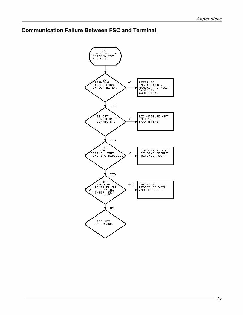
Appendices
75
Communication Failure Between FSC and Terminal

K800 Automated Fueling System
76 09/27/01
Display on FIT is Blank
DISPLAY IS BLANK.
ARE ALL INDICATORL LEDS "OFF" ON FIT PV247
IS CR-15 CR-18, 19, 20 FLASHING?
REPLACE PV247 FITBOARD.
ARE ALL THESE VOLTAGES PRESENT?
CHECK VOLTAGE ON POWER CABLE.
ORNG-ORNG 11 VACBRN-BRN 8VACRED-RED 11VAC.
CHECK INCOMING VOLTAGE 110 VAC.
IF INCOMING VOLTAGEIS PRESENT REPLACETRANSFORMER INSIDE FIT TERMINAL.
TRY ADJUSTING R94 ON PV247 BOARD. IF SAME RESULT REPLACE DISPLAY BOARD.
YES
NO
YES
NO
NO
YES

Appendices
77
Incorrect Readings (Optical & ChipKey Readers)
INCORRECT READING
DOES THIS MESSAGE
APPEAR WITH ALL CARDS OR
KEYS
ISOLATE PROBLEM BETWEEN READER MECHANISM AND
CONNECTING CABLE
INSPECT CARD OR KEY. REPLACE AS NECESSARY
YES
NO

K800 Automated Fueling System
78 06/02/00
MODEM DOES
NOT ANSWER
ISPHONE LINE
CONNECTED?
CONNECT
PHONE
CORRECTLY.
IS MODEM CABLE
CONNECTED?
CONNECT MODEMCABLE CORRECTLY.
REFER TOINSTALLATIONMANUAL.
VERIFY PHONE LINE
WORKS BY CONNECTING A
PHONE AND DIAL A CALL
OUT AND ALSO RECEIVE
A CALL IN.
DOESPHONE
LINE PASSTEST?
REPAIR LINE
AS NECESSARY.
RECONFIGURE
MODEM AND IF SAME
PROBLEM EXISTS,
REPLACE MODEM.
NO
YES
NO
YES
NO
YES
YES
Modem Does Not Answer

Appendices
79
Printer Not Printing Transactions
PRINTER NOTPRINTINGTRANSACTIONS.
ARE THE PRINTER
"READY' AND "ONLINE" LITES
ON?
TURN POWER OFF TOPRINTER FOR 5SECONDS AND TURNPOWER BACK ON TOPRINTER. IF SAMERESULT REPLACEPRINTER.
CHECK FSC TO SEE IF
DTR LITE IS ON.
REMOVE PRINTER CABLEFORM FSC. ON FSCPRINTER DIN CONNECTORJUMER CENTER PIN TOTOP RIGHT PIN. DOES THE PTR DTR COME ON NOW?
REPLACEFSCBOARD
CHECK NUMBER OFTRANSACTIONSSTORE IN FSC.SHOULD NOT EXCEED1800. MUST CLEARTRANS IF THIS IS THE CASE.
REPLACE PRINTER
NO
YES
NO NO
YESYES

K800 Automated Fueling System
80 06/02/00
"Pump Handle Re-Enter" Message
PUMP HANDLE ON,RE-ENTER
WAS PUMP HANDLE LEFT
ON FROM PREVIOUS FUELING?
TURN PUMP HANDLE
OFF AND RESELECT
PUMP!
PUT PUMP IN MANUAL USING
APPROPRIATE DIP SWITCH.
WITH PUMP HANDLE OFF, IS CURRENT
SENSE LIGHT ON?
TURN PUMP HANDLE ON AND WATCH
CURRENT SENSE LIGHT.
CHECK PUMP WIRING
TO PV240 CURRENT
SENSE CONTACTS
DOES CURRENT SENSE LIGHTCOME ON AFTER PUMP COMPLETES RESET CYCLE?
THIS IS THE CORRECTOPERATION OF THE CURRENT SENSE CIRCUIT. ISOLATE PROBLEM BY SUBSTITUTING PV240 & PV247 BDS.
YES
NO
YES
NO
YES
NO

Appendices
81
"System OFF" Message

K800 Automated Fueling System
82 06/02/00
Transformer VoltagesUse a voltmeter to check across the following points in your system FIT and FSC.
FIT/PCT
TEST ACROSSWIRE COLORS:
CIRCUIT PROPERVOLTAGE
BROWN����BROWN Petro-Net 8 VAC
ORANGE����ORANGE PCT and Heater 10.5 VAC
RED����RED System logic 10.5 VAC
FSC - The FSC plug-in power supply should produce 12 VAC.
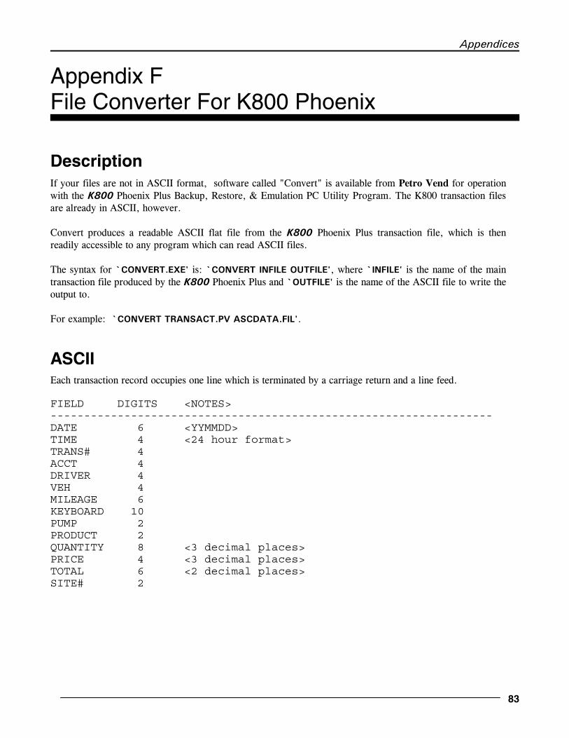
Appendices
83
Appendix FFile Converter For K800 Phoenix
DescriptionIf your files are not in ASCII format, software called "Convert" is available from Petro Vend for operationwith the K800 Phoenix Plus Backup, Restore, & Emulation PC Utility Program. The K800 transaction filesare already in ASCII, however.
Convert produces a readable ASCII flat file from the K800 Phoenix Plus transaction file, which is thenreadily accessible to any program which can read ASCII files.
The syntax for `CONVERT.EXE' is: `CONVERT INFILE OUTFILE', where `INFILE' is the name of the maintransaction file produced by the K800 Phoenix Plus and `OUTFILE' is the name of the ASCII file to write theoutput to.
For example: `CONVERT TRANSACT.PV ASCDATA.FIL'.
ASCIIEach transaction record occupies one line which is terminated by a carriage return and a line feed.
FIELD DIGITS <NOTES>------------------------------------------------------------------DATE 6 <YYMMDD>TIME 4 <24 hour format>TRANS# 4ACCT 4DRIVER 4VEH 4MILEAGE 6KEYBOARD 10PUMP 2PRODUCT 2QUANTITY 8 <3 decimal places>PRICE 4 <3 decimal places>TOTAL 6 <2 decimal places>SITE# 2

K800 Automated Fueling System
84 06/02/00
Example ASCII transaction record:
92041209520001000124672430769250??????????010100077600096800751202
SITE ))))))))))))))))))))))))))))))))))))))))))))))))))))))))))),TOTAL )))))))))))))))))))))))))))))))))))))))))))))))))))))), *PRICE ))))))))))))))))))))))))))))))))))))))))))))))))), * *QUANTITY ))))))))))))))))))))))))))))))))))))))))), * * *PRODUCT )))))))))))))))))))))))))))))))))))), * * * *PUMP ))))))))))))))))))))))))))))))))))))), * * * * *KEYBOARD )))))))))))))))))))))))))), * * * * * *MILEAGE ))))))))))))))))))), * * * * * * *VEHICLE ))))))))))))))), * * * * * * * *DRIVER )))))))))))), * * * * * * * * *ACCOUNT ))))))), * * * * * * * * * *TRANS ))))), * * * * * * * * * * *TIME )), * * * * * * * * * * * *DATE * * * * * * * * * * * * * * * * * * * * * * * * * * * * * * * * * * * * * * * * * * * * * * * * * * * * * * * * * * * * * * * * * * * * *+))2),+2),+2),+2),+2),+2),+)2)),+)))2)))),/,/,+)))2)),+2),+)2)),/,* ** ** ** ** ** ** ** ****** ** ** ***^ ^^ ^^ ^^ ^^ ^^ ^^ ^^ ^^^^^^ ^^ ^^ ^^^ 92041209520001000124672430769250??????????010100077600096800751202
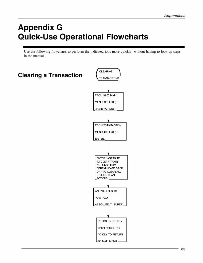
Appendices
85
Appendix GQuick-Use Operational Flowcharts
Use the following flowcharts to perform the indicated jobs more quickly, without having to look up stepsin the manual.
Clearing a TransactionCLEARING
TRANSACTIONS
FROM K800 MAIN
MENU, SELECT (E)
TRANSACTIONS.
FROM TRANSACTION
MENU, SELECT (D)
ERASE.
ENTER LAST DATETO CLEAR TRANS-ACTIONS FROMCERTAIN DATE BACKOR * TO CLEAR ALLSTORED TRANS-ACTIONS.
ANSWER YES TO
"ARE YOU
ABSOLUTELY SURE?"
PRESS ENTER KEY,
THEN PRESS THE
"X" KEY TO RETURN
TO MAIN MENU.

K800 Automated Fueling System
86 06/02/00
Entering Files and Accounts
PROGRAMMING ACCOUNTS INTO SYSTEM.
PROGRAMMINGCARDS INTOSYSTEM CARD FILE.
SELECT (D) CARD/KEY/ACCOUNT FILE FROM K800 MAIN MENU.
SELECT (D) CARD/KEY/ACCOUNT FILEFROM K800 MAINMENU.
SELECT (B) EDIT
USER FILE.
SELECT (D) EDIT
ACCOUNT FILE.
ENTER 4 DIGITCARD NUMBER YOU WISH TO PROGRAM INTO SYSTEM.(0000-9999)
ANSWER "YES" TOCHANGE AND FOLLOW THE PROMPTS ACCORDINGLY.
PRESS "ESC" KEYTO RETURN BACKTO MAIN MENU.
PRESS "ESC" KEYTO RETURN BACKTO MAIN MENU.
ANSWER "YES" TO CHANGE AND FOLLOW THE PROMPTS ACCORDINGLY.
ENTER 3 DIGITACOUNT(000-250)NUMBER.

Appendices
87
Programming Pump Information
PROGRAMMING
PUMP
PARAMETERS.
SELECT (B) SITE
CONFIGURATION
FROM K800 MAIN
MENU.
SELECT (B)
PUMP
CONFIGURATION.
ENTER YES TO
CHANGE AND ENTER
# IF YOU WISH TO
PROGRAM.
PRESS "ESC" KEY
TO RETURN BACK
TO MAIN MENU.
FOLLOW AND
ANSWER PROMPTS
ACCORDINGLY.

K800 Automated Fueling System
88 06/02/00
Running a Report Package
RUNNING
REPORT
PACKAGE
SELECT (F)
REPORTS FROM
K800 MAIN MENU.
SELECT (R)
REPORT PACKAGE
FROM REPORT
MENU.
PRESS "R" TO
RUN REPORT AND
ANSWER ALL
QUESTIONS
AFTER REPORT IS
FINISHED PRESS "Q" TO
QUIT AND PRESS "X" TO
RETURN TO MAIN MENU.

K800 Automated Fueling System
89
Index.
Access time restriction 27Account files 37Account number 36Battery backup 8Card compatibility 2Card entries 10Cardless entry 5ChipKey programming 57ChipKeys 1Cold start 13Command entry 9Computer, external 7Cool start 14Date and time 9Daylight savings 18Description 1Emergency stop 6Encoding procedure 60EPROMs 55Erase feature 40Features 2File converter 75FIT (Fuel Island Terminal)
Card readers 5Cleaning 6Display 6Installation 5Messages 28
Flowcharts for troubleshooting 65FSC (Fuel Site Controller)
Installation 7Transformers 7
FSC specifications 4Inventory report 45Keyboard message 34Keypad 6Lock terminal 16Max transactions per day 35Menu overview 15Messages 28Mileage flag 34Mileage reasonability 58Modem 8Modem password 54Modems 53MPD (Missing Pulse Detect) 22Not Available message 64Odometer reasonability 57Passwords 19Petro Net specifications 3PIN (Personal Identification Number) 35
Poll data format 51Polling 40Port speeds 4Power requirements 3Power-up 13Printer, journal 8Printing reports 46Product name 25Product number 21Product Totals report 44Pulser compatibility 3Pulser divide rate 22Pump In Use message 64Pump number 21Pump parameters 9Pump parameters, setting 19Pump Sentry 22Pump Totals report 43Quantity restriction 21Quick-Use flowcharts 77QUIT command 16Recall feature 39Report package (OPTIONAL) 47Reports 12Reports menu 41Required settings 10Restrictions 10, 26Service warnings 59Site Configuration menu 19Site name 18Site setup 16Specifications 3STATUS light codes 63Status, pump 21System Info report 42System Setup menu 17Tables menu 25Tank parameters 9Tank, supply 21Temperature ratings 3Terminal emulation 13Time and date 9Time for fueling 22Time for Pump Handle 22Time of day 17Transaction detail 11Transactions menu 39Troubleshooting 62User files, editing 33User files, showing 32Validation status 37

OPW Fuel Management Systems 6900 Santa Fe Drive Hodgkins, IL 60525
708-485-4200