M-SERIES SINGLE ZONE SYSTEMS MSZ/MUZ-GE …...MSZ/MUZ-GE-NA2 WALL-MOUNT HEAT PUMP SYSTEMS 1. INDOOR...
48
M-Series - MSZ/MUZ-GENA2 Heat Pump Systems (August 2014) MSZ-GENA2-1 © 2014 Mitsubishi Electric US, Inc. Due to continuing improvement, above specification may be subject to change without notice. M-SERIES SINGLE ZONE SYSTEMS MSZ/MUZ-GE-NA2 WALL-MOUNT HEAT PUMP SYSTEMS 1. INDOOR UNITS ..........................................................................................................................................MSZ-GE-NA2-3 2. OUTDOOR UNITS ......................................................................................................................................MSZ-GE-NA2-4 3. SYSTEM......................................................................................................................................................MSZ-GE-NA2-5 3-1. SPECIFICATIONS ...................................................................................................................................MSZ-GE-NA2-6 MSZ-GE06NA-8 MSZ-GE09NA-8 MSZ-GE12NA-8 MSZ-GE15NA-8 MSZ-GE18NA-8 .......................MSZ-GE-NA2-6 MSZ-GE24NA............................................................................................................................................MSZ-GE-NA2-7 MUZ-GE09NA2 MUZ-GE12NA2 ..............................................................................................................MSZ-GE-NA2-8 MUZ-GE15NA2 MUZ-GE18NA-1 .............................................................................................................MSZ-GE-NA2-9 MUZ-GE24NA .........................................................................................................................................MSZ-GE-NA2-10 Efficiency ratings ..................................................................................................................................... MSZ-GE-NA2-11 3-2. EXTERNAL DIMENSIONS.....................................................................................................................MSZ-GE-NA2-12 MSZ-GE06NA-8 MSZ-GE09NA-8 MSZ-GE12NA-8 MSZ-GE15NA-8 MSZ-GE18NA-8 .....................MSZ-GE-NA2-12 MSZ-GE24NA..........................................................................................................................................MSZ-GE-NA2-13 MUZ-GE09NA2 MUZ-GE12NA2 MUZ-GE15NA2 .................................................................................MSZ-GE-NA2-14 MUZ-GE18NA-1 ......................................................................................................................................MSZ-GE-NA2-15 MUZ-GE24NA .........................................................................................................................................MSZ-GE-NA2-16 3-3. CENTER OF GRAVITY ..........................................................................................................................MSZ-GE-NA2-17 3-4. ELECTRICAL WIRING DIAGRAMS.......................................................................................................MSZ-GE-NA2-18 MSZ-GE06NA-8 MSZ-GE09NA-8 MSZ-GE12NA-8 MSZ-GE15NA-8 MSZ-GE18NA-8 .....................MSZ-GE-NA2-18 MSZ-GE24NA..........................................................................................................................................MSZ-GE-NA2-19 MUZ-GE09NA2 MUZ-GE12NA2 ............................................................................................................MSZ-GE-NA2-20 MUZ-GE15NA2 .......................................................................................................................................MSZ-GE-NA2-21 MUZ-GE18NA-1 ......................................................................................................................................MSZ-GE-NA2-22 MUZ-GE24NA .........................................................................................................................................MSZ-GE-NA2-23 3-5. REFRIGERANT SYSTEM DIAGRAMS .................................................................................................MSZ-GE-NA2-24 MSZ-GE06NA-8 MSZ-GE09NA-8 MSZ-GE12NA-8 MSZ-GE15NA-8 MSZ-GE18NA-8 .....................MSZ-GE-NA2-24 MUZ-GE12NA2 MUZ-GE15NA2 ...........................................................................................................MSZ-GE-NA2-25 MUZ-GE18NA-1 ......................................................................................................................................MSZ-GE-NA2-26 MUZ-GE24NA .........................................................................................................................................MSZ-GE-NA2-26 3-6. CAPACITY CORRECTION CURVE BY TEMPERATURE .....................................................................MSZ-GE-NA2-27 (1) Cooling...............................................................................................................................................MSZ-GE-NA2-27 (2) Heating...............................................................................................................................................MSZ-GE-NA2-28 3-7. CAPACITY CORRECTION TABLE BY TEMPERATURE.......................................................................MSZ-GE-NA2-29 (1) Cooling Capacity...............................................................................................................................MSZ-GE-NA2-29 (2) Heating Capacity...............................................................................................................................MSZ-GE-NA2-30 3-8. CAPACITY CORRECTION CURVE BY REFRIGERANT PIPING LENGTH..........................................MSZ-GE-NA2-32 3-9. CAPACITY CORRECTION TABLE BY REFRIGERANT PIPING LENGTH ...........................................MSZ-GE-NA2-33 (1) Cooling Capacity Correction ..............................................................................................................MSZ-GE-NA2-33 (2) Maximum Refrigerant Piping Length & Maximum Height Difference.................................................MSZ-GE-NA2-33
Transcript of M-SERIES SINGLE ZONE SYSTEMS MSZ/MUZ-GE …...MSZ/MUZ-GE-NA2 WALL-MOUNT HEAT PUMP SYSTEMS 1. INDOOR...

M-Series - MSZ/MUZ-GENA2 Heat Pump Systems (August 2014) MSZ-GENA2-1© 2014 Mitsubishi Electric US, Inc.
Due to continuing improvement, above specification may be subject to change without notice.
M-SERIES SINGLE ZONE SYSTEMS
MSZ/MUZ-GE-NA2 WALL-MOUNT HEAT PUMP SYSTEMS1. INDOOR UNITS ..........................................................................................................................................MSZ-GE-NA2-3
2. OUTDOOR UNITS ......................................................................................................................................MSZ-GE-NA2-4
3. SYSTEM ......................................................................................................................................................MSZ-GE-NA2-5
3-1. SPECIFICATIONS ...................................................................................................................................MSZ-GE-NA2-6MSZ-GE06NA-8 MSZ-GE09NA-8 MSZ-GE12NA-8 MSZ-GE15NA-8 MSZ-GE18NA-8 .......................MSZ-GE-NA2-6MSZ-GE24NA............................................................................................................................................MSZ-GE-NA2-7MUZ-GE09NA2 MUZ-GE12NA2 ..............................................................................................................MSZ-GE-NA2-8MUZ-GE15NA2 MUZ-GE18NA-1 .............................................................................................................MSZ-GE-NA2-9MUZ-GE24NA .........................................................................................................................................MSZ-GE-NA2-10Efficiency ratings .....................................................................................................................................MSZ-GE-NA2-11
3-2. EXTERNAL DIMENSIONS.....................................................................................................................MSZ-GE-NA2-12MSZ-GE06NA-8 MSZ-GE09NA-8 MSZ-GE12NA-8 MSZ-GE15NA-8 MSZ-GE18NA-8 .....................MSZ-GE-NA2-12MSZ-GE24NA..........................................................................................................................................MSZ-GE-NA2-13MUZ-GE09NA2 MUZ-GE12NA2 MUZ-GE15NA2 .................................................................................MSZ-GE-NA2-14MUZ-GE18NA-1 ......................................................................................................................................MSZ-GE-NA2-15MUZ-GE24NA .........................................................................................................................................MSZ-GE-NA2-16
3-3. CENTER OF GRAVITY ..........................................................................................................................MSZ-GE-NA2-17
3-4. ELECTRICAL WIRING DIAGRAMS.......................................................................................................MSZ-GE-NA2-18MSZ-GE06NA-8 MSZ-GE09NA-8 MSZ-GE12NA-8 MSZ-GE15NA-8 MSZ-GE18NA-8 .....................MSZ-GE-NA2-18MSZ-GE24NA..........................................................................................................................................MSZ-GE-NA2-19MUZ-GE09NA2 MUZ-GE12NA2 ............................................................................................................MSZ-GE-NA2-20MUZ-GE15NA2 .......................................................................................................................................MSZ-GE-NA2-21MUZ-GE18NA-1 ......................................................................................................................................MSZ-GE-NA2-22MUZ-GE24NA .........................................................................................................................................MSZ-GE-NA2-23
3-5. REFRIGERANT SYSTEM DIAGRAMS .................................................................................................MSZ-GE-NA2-24MSZ-GE06NA-8 MSZ-GE09NA-8 MSZ-GE12NA-8 MSZ-GE15NA-8 MSZ-GE18NA-8 .....................MSZ-GE-NA2-24MUZ-GE12NA2 MUZ-GE15NA2 ...........................................................................................................MSZ-GE-NA2-25MUZ-GE18NA-1 ......................................................................................................................................MSZ-GE-NA2-26MUZ-GE24NA .........................................................................................................................................MSZ-GE-NA2-26
3-6. CAPACITY CORRECTION CURVE BY TEMPERATURE .....................................................................MSZ-GE-NA2-27(1) Cooling ...............................................................................................................................................MSZ-GE-NA2-27(2) Heating...............................................................................................................................................MSZ-GE-NA2-28
3-7. CAPACITY CORRECTION TABLE BY TEMPERATURE .......................................................................MSZ-GE-NA2-29 (1) Cooling Capacity ...............................................................................................................................MSZ-GE-NA2-29 (2) Heating Capacity...............................................................................................................................MSZ-GE-NA2-30
3-8. CAPACITY CORRECTION CURVE BY REFRIGERANT PIPING LENGTH..........................................MSZ-GE-NA2-32
3-9. CAPACITY CORRECTION TABLE BY REFRIGERANT PIPING LENGTH ...........................................MSZ-GE-NA2-33(1) Cooling Capacity Correction ..............................................................................................................MSZ-GE-NA2-33(2) Maximum Refrigerant Piping Length & Maximum Height Difference .................................................MSZ-GE-NA2-33

MSZ-GENA2-2 M-Series - MSZ/MUZ-GENA2 Heat Pump Systems (August 2014)
Due to continuing improvement, above specification may be subject to change without notice.
© 2014 Mitsubishi Electric US, Inc.
3-10. CHARGE CALCULATIONS .................................................................................................................MSZ-GE-NA2-35(1) Additional Refrigerant Charge (R410a: Oz.) ......................................................................................MSZ-GE-NA2-35
3-11. AIR FLOW DATA ..................................................................................................................................MSZ-GE-NA2-36Outlet Air Speed And Coverage ..............................................................................................................MSZ-GE-NA2-36
3-12. SOUND PRESSURE LEVELS .............................................................................................................MSZ-GE-NA2-37(1) Indoor Unit .........................................................................................................................................MSZ-GE-NA2-37(2) Outdoor Unit.......................................................................................................................................MSZ-GE-NA2-38
3-13. STANDARD OPERATION RANGE ......................................................................................................MSZ-GE-NA2-40
3-14. MAXIMUM HEATING CAPACITY IN LOW AMBIENT TEMPERATURE ..............................................MSZ-GE-NA2-41
3-15. ACCESSORIES ...................................................................................................................................MSZ-GE-NA2-44(1) Indoor Unit .........................................................................................................................................MSZ-GE-NA2-44(2) Outdoor Unit.......................................................................................................................................MSZ-GE-NA2-47
M-SERIES SINGLE ZONE SYSTEMS
M-Series - MSZ/MUZ-GENA2 Heat Pump Systems (August 2014) MSZ-GENA2-3© 2014 Mitsubishi Electric US, Inc.
Due to continuing improvement, above specification may be subject to change without notice.
1. INDOOR UNITS
• MSZ-GE06NA-8*• MSZ-GE09NA-8• MSZ-GE12NA-8• MSZ-GE15NA-8• MSZ-GE18NA-8• MSZ-GE24NA
*The MSZ-GE06NA-8 is only compatible with the multi-split MXZ heat pump systems.
3-10. CHARGE CALCULATIONS .................................................................................................................MSZ-GE-NA2-35(1) Additional Refrigerant Charge (R410a: Oz.) ......................................................................................MSZ-GE-NA2-35
3-11. AIR FLOW DATA ..................................................................................................................................MSZ-GE-NA2-36Outlet Air Speed And Coverage ..............................................................................................................MSZ-GE-NA2-36
3-12. SOUND PRESSURE LEVELS .............................................................................................................MSZ-GE-NA2-37(1) Indoor Unit .........................................................................................................................................MSZ-GE-NA2-37(2) Outdoor Unit.......................................................................................................................................MSZ-GE-NA2-38
3-13. STANDARD OPERATION RANGE ......................................................................................................MSZ-GE-NA2-40
3-14. MAXIMUM HEATING CAPACITY IN LOW AMBIENT TEMPERATURE ..............................................MSZ-GE-NA2-41
3-15. ACCESSORIES ...................................................................................................................................MSZ-GE-NA2-44(1) Indoor Unit .........................................................................................................................................MSZ-GE-NA2-44(2) Outdoor Unit.......................................................................................................................................MSZ-GE-NA2-47

MSZ-GENA2-4 M-Series - MSZ/MUZ-GENA2 Heat Pump Systems (August 2014)
Due to continuing improvement, above specification may be subject to change without notice.
© 2014 Mitsubishi Electric US, Inc.
2. OUTDOOR UNITS
• MUZ-GE09NA2• MUZ-GE12NA2• MUZ-GE15NA2• MUZ-GE18NA-1• MUZ-GE24NA

M-Series - MSZ/MUZ-GENA2 Heat Pump Systems (August 2014) MSZ-GENA2-5© 2014 Mitsubishi Electric US, Inc.
Due to continuing improvement, above specification may be subject to change without notice.
3. SYSTEM• Wall-mounted indoor unit for residential application• Standard Hybrid Catechin Prefilter and anti-allergy enzyme filter for high air-purification abilities• Quiet operation• Updated sleek, compact indoor unit design• Base heater is available as an option• Auto fan speed control: Quiet, Low, Medium, High, and Super High• Hand-held Wireless Remote Controller• Advanced microprocessor control• Auto restart following a power outage• Anti-allergy Enzyme Filter• Limited warranty: five years parts and seven years compressor

MSZ-GENA2-6 M-Series - MSZ/MUZ-GENA2 Heat Pump Systems (August 2014)
Due to continuing improvement, above specification may be subject to change without notice.
© 2014 Mitsubishi Electric US, Inc.
3-1. SPECIFICATIONS
Model name MSZ-GE06NA-8 MSZ-GE09NA-8 MSZ-GE12NA-8
Power supply V, phase, Hz 208/230, 1, 60
Max. fuse size (time delay)/ Disconnect switch A 15
Min. circuit ampacity A 1.0
Blower Motor (ECM) F.L.A 0.76
AirflowSuper High - High - Med. - Low - Quiet
COOL Dry (Wet) CFM 399-321-237-170-145
(364-286-201-134-109)
HEAT Dry CFM 406-321-233-170-145 406-321-237-170-145
Moisture removal pt./h – 1.5 2.5
Sensible Heat Factor 0.82 0.74 0.80
Sound levelSuper High - High - Med. - Low - Quiet
Cooling dB(A)43-37-30-22-19
45-37-30-22-19
Heating dB(A) 43-37-30-22-19
Cond. drain connection O.D. in. 5/8
Dimensions
W
in.
31-7/16
D 9-1/8
H 11-5/8
Weight Ib. 22
External finish Munsell 1.0Y 9.2/0.2
Control voltage (by built-in transformer) 12 - 24 VDC
Model name MSZ-GE15NA-8 MSZ-GE18NA-8
Power supply V, phase, Hz 208/230, 1, 60
Max. fuse size (time delay)/ Disconnect switch A 15
Min. circuit ampacity A 1.0
Blower Motor (ECM) F.L.A 0.76
AirflowSuper High - High - Med. - Low - Quiet
COOL Dry (Wet) CFM 533-420-335-272-205
(498-385-300-237-170)533-420-339-275-230
( 498-385-304-240-194)
HEAT Dry CFM 463-367-304-247-205 512-431-339-275-230
Moisture removal pt./h 2.7 4.6
Sensible Heat Factor 0.71 0.75
Sound levelSuper High - High - Med. - Low - Quiet
Cooling dB(A) 49-44-38-32-26 49-44-38-33-28
Heating dB(A) 46-40-35-30-26 49-43-38-33-28
Cond. drain connection O.D. in. 5/8
Dimensions
W
in.
31-7/16
D 9-1/8
H 11-5/8
Weight Ib. 22
External finish Munsell 1.0Y 9.2/0.2
Control voltage (by built-in transformer) 12 - 24 VDC NOTE: Test conditions are based on ARI 210/240.
MSZ-GE06NA-8 MSZ-GE09NA-8 MSZ-GE12NA-8 MSZ-GE15NA-8 MSZ-GE18NA-8
M-Series - MSZ/MUZ-GENA2 Heat Pump Systems (August 2014) MSZ-GENA2-7© 2014 Mitsubishi Electric US, Inc.
Due to continuing improvement, above specification may be subject to change without notice.
3-1. SPECIFICATIONS
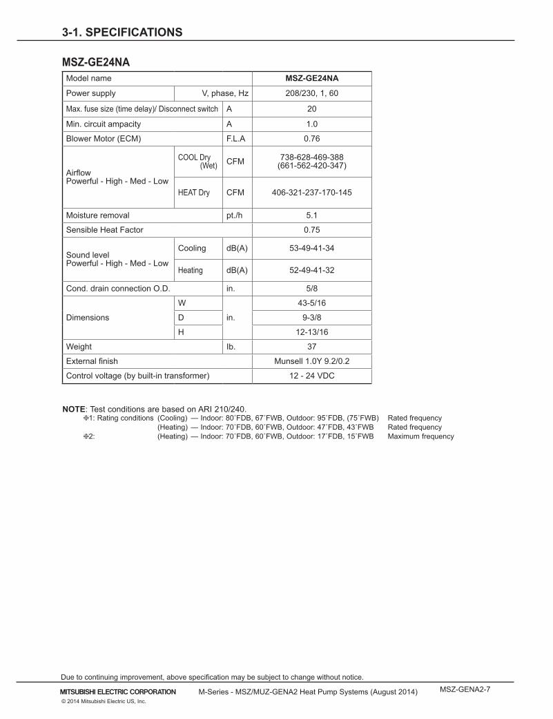
Model name MSZ-GE24NA
Power supply V, phase, Hz 208/230, 1, 60
Max. fuse size (time delay)/ Disconnect switch A 20
Min. circuit ampacity A 1.0
Blower Motor (ECM) F.L.A 0.76
AirflowPowerful - High - Med - Low
COOL Dry (Wet) CFM 738-628-469-388
(661-562-420-347)
HEAT Dry CFM 406-321-237-170-145
Moisture removal pt./h 5.1
Sensible Heat Factor 0.75
Sound levelPowerful - High - Med - Low
Cooling dB(A) 53-49-41-34
Heating dB(A) 52-49-41-32
Cond. drain connection O.D. in. 5/8
Dimensions
W
in.
43-5/16
D 9-3/8
H 12-13/16
Weight Ib. 37
External finish Munsell 1.0Y 9.2/0.2
Control voltage (by built-in transformer) 12 - 24 VDC
NOTE: Test conditions are based on ARI 210/240. 1: Rating conditions (Cooling) — Indoor: 80˚FDB, 67˚FWB, Outdoor: 95˚FDB, (75˚FWB) Rated frequency (Heating) — Indoor: 70˚FDB, 60˚FWB, Outdoor: 47˚FDB, 43˚FWB Rated frequency 2: (Heating) — Indoor: 70˚FDB, 60˚FWB, Outdoor: 17˚FDB, 15˚FWB Maximum frequency
MSZ-GE24NA

MSZ-GENA2-8 M-Series - MSZ/MUZ-GENA2 Heat Pump Systems (August 2014)
Due to continuing improvement, above specification may be subject to change without notice.
© 2014 Mitsubishi Electric US, Inc.
3-1. SPECIFICATIONS
Model name MUZ-GE09NA2 MUZ-GE12NA2
Capacity Rated (Minimum~Maximum)
Cooling 1 Btu/h 9,000( 3,800 ~ 12,200 )
12,000( 3,800 ~ 13,600 )
Heating 47 1 Btu/h 10,900( 4,500 ~ 14,100 )
14,400( 5,500 ~ 18,100 )
CapacityRated (Maximum) Heating 17 2 Btu/h 6,600 (8,700) 8,800 (11,200)
Power consumption Rated (Minimum~Maximum)
Cooling 1 W 660 (205~1,200) 960 (205~1,300)
Heating 47 1 W 760 (255~1,200) 1,170 (340~1,660)Power consumptionRated (Maximum) Heating 17 2 W 700 (950) 900 (1,200)
EER 1 [SEER] 3 Cooling 13.6 [23.2] 12.5 [22.7]
HSPF IV 4 Heating 11.0 11.4
COP Heating 1 4.20 3.61
Power supply V , phase , Hz 208/230 , 1 , 60
Max. fuse size (time delay) A 15
Min. circuit ampacity A 12 12
Fan Motor (ECM) F.L.A 0.50
Compressor
Model KNB073FQDHC KNB092FQAHC
R.L.A 6.6 6.6
L.R.A 8.2 8.2
Refrigeration oil Fl.Oz. (Type) 10.22 (NEO22)
Refrigerant control Linear expansion valve
Sound level 1Cooling dB(A) 46 49
Heating dB(A) 50 51
Defrost method Reverse cycle
Dimensions
W in. 31-1/2
D in. 11-1/4
H in. 21-5/8
Weight Ib. 66 77
External finish Munsell 3Y 7.8/1.1
Remote controller Wireless type
Control voltage (by built-in transformer) VDC 12 - 24
Refrigerant piping Not supplied
Refrigerant pipe size (Min. wall thickness)
Liquid in. 1/4 (0.0315)
Gas in. 3/8 (0.0315)
Connection method Indoor Flared
Outdoor Flared
Between the indoor & outdoor units
Height difference ft. 40
Piping length ft. 65
Refrigerant charge (R410A) 1 lb. 12 oz. 2 lb. 9 oz. NOTE: Test conditions are based on ARI 210/240. 1: Rating conditions (Cooling) — Indoor: 80˚FDB, 67˚FWB, Outdoor: 95˚FDB, (75˚FWB) Rated frequency (Heating) — Indoor: 70˚FDB, 60˚FWB, Outdoor: 47˚FDB, 43˚FWB Rated frequency 2: (Heating) — Indoor: 70˚FDB, 60˚FWB, Outdoor: 17˚FDB, 15˚FWB Maximum frequency
MUZ-GE09NA2 MUZ-GE12NA2

M-Series - MSZ/MUZ-GENA2 Heat Pump Systems (August 2014) MSZ-GENA2-9© 2014 Mitsubishi Electric US, Inc.
Due to continuing improvement, above specification may be subject to change without notice.
3-1. SPECIFICATIONS
Model name MUZ-GE15NA2 MUZ-GE18NA-1
Capacity Rated (Minimum~Maximum)
Cooling 1 Btu/h 14,000( 3,100 ~ 18,200 )
17,200( 3,700 ~ 18,700 )
Heating 47 1 Btu/h 18,000( 4,800 ~ 20,900 )
21,600( 3,500 ~ 25,200 )
CapacityRated (Maximum) Heating 17 2 Btu/h 11,300 (15,900) 13,400 (17,200)
Power con-sumption Rated (Minimum~Maximum)
Cooling 1 W 1,080 (160 ~ 2,000) 1,640 (240 ~ 2,070)
Heating 47 1 W 1,600 (270 ~ 2,010) 1,900 (230 ~ 2,680)Power consumptionRated (Maximum) Heating 17 2 W 1,150 (1,950) 1,450 (2,080)
EER 1 [SEER] 3 Cooling 13.6 [ 21.6] 10.5 [19.2]
HSPF IV 4 Heating 11.2 10.0
COP Heating 1 3.30 3.33
Power supply V , phase , Hz 208/230 , 1 , 60
Max. fuse size (time delay) A 15
Min. circuit ampacity A 12 14
Fan Motor (ECM) F.L.A 0.50 0.93
Compressor
Model SNB130FQBH
R.L.A 7.4 10.0
L.R.A 9.3 12.5
Refrigeration oil Fl.Oz. (Type) 15.2 (NEO22)
Refrigerant control Linear expansion valve
Sound level 1Cooling dB(A) 49 54
Heating dB(A) 51 56
Defrost method Reverse cycle
Dimensions
W in. 31-1/2 33-1/16
D in. 11-1/4 13
H in. 21-5/8 33-7/16
Weight Ib. 80 119
External finish Munsell 3Y 7.8/1.1
Remote controller Wireless type
Control voltage (by built-in transformer) VDC 12 - 24
Refrigerant piping Not supplied
Refrigerant pipe size (Min. wall thickness)
Liquid in. 1/4 (0.0315)
Gas in. 1/2 (0.0315)
Connection method Indoor Flared
Outdoor Flared
Between the indoor & outdoor units
Height difference ft. 40 50
Piping length ft. 65 100
Refrigerant charge (R410A) 2 lb. 9 oz. 3 lb. 7 oz. NOTE: Test conditions are based on ARI 210/240. 1: Rating conditions (Cooling) — Indoor: 80˚FDB, 67˚FWB, Outdoor: 95˚FDB, (75˚FWB) Rated frequency (Heating) — Indoor: 70˚FDB, 60˚FWB, Outdoor: 47˚FDB, 43˚FWB Rated frequency 2: (Heating) — Indoor: 70˚FDB, 60˚FWB, Outdoor: 17˚FDB, 15˚FWB Maximum frequency
MUZ-GE15NA2 MUZ-GE18NA-1

MSZ-GENA2-10 M-Series - MSZ/MUZ-GENA2 Heat Pump Systems (August 2014)
Due to continuing improvement, above specification may be subject to change without notice.
© 2014 Mitsubishi Electric US, Inc.
3-1. SPECIFICATIONS
MUZ-GE24NAModel name MUZ-GE24NA
Capacity Rated (Minimum~Maximum)
Cooling 1 Btu/h 22,500(8,200 ~ 31,400)
Heating 47 1 Btu/h 27,600(7,500 ~ 36,900)
Capacity Rated (Maximum) Heating 17 2 Btu/h 16,000 (24,600)
Power consumption Rated (Minimum~Maximum)
Cooling 1 W 1,800 (570 ~ 3,580)
Heating 47 1 W 2,340 (520 ~ 3,650)
Power consumption Heating 17 2 W 1,770 (3,290)
EER 1 [SEER] 3 Cooling 12.5 [19.0]
HSPF IV 4 Heating 10.0
COP Heating 1 3.46
Power supply V , phase , Hz 208/230 , 1 , 60
Max. fuse size (time delay) A 20
Min. circuit ampacity A 17.1
Fan Motor (ECM) F.L.A 0.93
Compressor
Model SNB172FQKMT
R.L.A 12.9
L.R.A 16.1
Refrigeration oil cc. (Model) 0.40 (FV50S)
Refrigerant control Linear expansion valve
Sound level 1Cooling dB(A) 55
Heating dB(A) 55
Defrost method Reverse Cycle
Dimensions
W in. 33-1/16
D in. 13
H in. 34-5/8
Weight Ib. 119
External finish Munsell 3Y 7.8/1.1
Remote controller Wireless type
Control voltage (by built-in transformer) VDC 12 - 24
Refrigerant piping Not supplied
Refrigerant pipe size (Min. wall thickness)
Liquid in. 3/8 (0.0315)
Gas in. 5/8 (0.0315)
Connection method Indoor Flared
Outdoor Flared
Between the indoor & outdoor units
Height difference ft. 50
Piping length ft. 100
Refrigerant charge (R410A) 4 lb. 3 oz. NOTE: Test conditions are based on ARI 210/240. 1: Rating conditions (Cooling) — Indoor: 80˚FDB, 67˚FWB, Outdoor: 95˚FDB, (75˚FWB) Rated frequency (Heating) — Indoor: 70˚FDB, 60˚FWB, Outdoor: 47˚FDB, 43˚FWB Rated frequency 2: (Heating) — Indoor: 70˚FDB, 60˚FWB, Outdoor: 17˚FDB, 15˚FWB Maximum frequency

M-Series - MSZ/MUZ-GENA2 Heat Pump Systems (August 2014) MSZ-GENA2-11© 2014 Mitsubishi Electric US, Inc.
Due to continuing improvement, above specification may be subject to change without notice.
3-1. SPECIFICATIONS
Efficiency ratings
Outdoor Unit Indoor Unit SEER EER HSPF COP @ 47° F
COP @ 17° F
Energy Star
Tax Credit
WALL-MOUNT HEAT PUMPMUZ-GE09NA2 MSZ-GE09NA-8 23.20 13.6 11.0 4.20 2.76 Yes Yes
MUZ-GE12NA2 MSZ-GE12NA-8 22.70 12.5 11.4 3.61 2.87 Yes Yes
MUZ-GE15NA2 MSZ-GE15NA-8 21.60 13.0 11.2 3.30 2.88 Yes Yes
MUZ-GE18NA-1 MSZ-GE18NA-8 19.20 10.5 10.0 3.32 2.70
MUZ-GE24NA MSZ-GE24NA 19.00 12.5 10.0 3.46 2.64 Yes Yes
Note: Efficiency values based on AHRI 210/240 test method.
Model name MUZ-GE24NA
Capacity Rated (Minimum~Maximum)
Cooling 1 Btu/h 22,500(8,200 ~ 31,400)
Heating 47 1 Btu/h 27,600(7,500 ~ 36,900)
Capacity Rated (Maximum) Heating 17 2 Btu/h 16,000 (24,600)
Power consumption Rated (Minimum~Maximum)
Cooling 1 W 1,800 (570 ~ 3,580)
Heating 47 1 W 2,340 (520 ~ 3,650)
Power consumption Heating 17 2 W 1,770 (3,290)
EER 1 [SEER] 3 Cooling 12.5 [19.0]
HSPF IV 4 Heating 10.0
COP Heating 1 3.46
Power supply V , phase , Hz 208/230 , 1 , 60
Max. fuse size (time delay) A 20
Min. circuit ampacity A 17.1
Fan Motor (ECM) F.L.A 0.93
Compressor
Model SNB172FQKMT
R.L.A 12.9
L.R.A 16.1
Refrigeration oil cc. (Model) 0.40 (FV50S)
Refrigerant control Linear expansion valve
Sound level 1Cooling dB(A) 55
Heating dB(A) 55
Defrost method Reverse Cycle
Dimensions
W in. 33-1/16
D in. 13
H in. 34-5/8
Weight Ib. 119
External finish Munsell 3Y 7.8/1.1
Remote controller Wireless type
Control voltage (by built-in transformer) VDC 12 - 24
Refrigerant piping Not supplied
Refrigerant pipe size (Min. wall thickness)
Liquid in. 3/8 (0.0315)
Gas in. 5/8 (0.0315)
Connection method Indoor Flared
Outdoor Flared
Between the indoor & outdoor units
Height difference ft. 50
Piping length ft. 100
Refrigerant charge (R410A) 4 lb. 3 oz. NOTE: Test conditions are based on ARI 210/240. 1: Rating conditions (Cooling) — Indoor: 80˚FDB, 67˚FWB, Outdoor: 95˚FDB, (75˚FWB) Rated frequency (Heating) — Indoor: 70˚FDB, 60˚FWB, Outdoor: 47˚FDB, 43˚FWB Rated frequency 2: (Heating) — Indoor: 70˚FDB, 60˚FWB, Outdoor: 17˚FDB, 15˚FWB Maximum frequency

MSZ-GENA2-12 M-Series - MSZ/MUZ-GENA2 Heat Pump Systems (August 2014)
Due to continuing improvement, above specification may be subject to change without notice.
© 2014 Mitsubishi Electric US, Inc.
3-2. EXTERNAL DIMENSIONS
MSZ-GE06NA-8 MSZ-GE09NA-8 MSZ-GE12NA-8 MSZ-GE15NA-8 MSZ-GE18NA-8
8-5/16
9-1/8
9-15/16
7/8
6-1/
86-
1/8
3-1/
83-
1/8
8-7/
88-
7/8
1/8
3/4
6 - 1/4
2- 5
/16
3/16
9-1/
8
2-3/162-3/4
31-7
/16
30-1
5/16
1/4
5-1/
824
-3/8
1-15
/16
11-5/8
1-15
/16
1-5/8
2-3/
16
1-11/16
1-5/
8
5/16
3-15/16
4/3/
16
4-3/
8
1-3/
4
2-3/162-11/16
13-5
/16
2-3/
8
8-3/810
1-5/8
1-5/8
13-9
/16
2-1/
8
7/16
×1 O
blon
g ho
le7/
16×1
3/16
Obl
ong
hole
Inst
alla
tion
plat
e
Indo
or u
nit
Wal
l hol
e ø2
-9/1
6Ai
r in
Air o
ut
Inst
alla
tion
plat
e
Pipi
ng
Drai
n ho
se

M-Series - MSZ/MUZ-GENA2 Heat Pump Systems (August 2014) MSZ-GENA2-13© 2014 Mitsubishi Electric US, Inc.
Due to continuing improvement, above specification may be subject to change without notice.
3-2. EXTERNAL DIMENSIONS
Unit: inchMSZ-GE24NA
42-7
/83/1
643
-5/16
1-3/49-3/810-3/16
1/8
11
8-7/8
8-7/8
5-1/16
9-7/1611-1/16
1-3/4
1-15
/1619
-3/4
17-5
/167-
27/32
7-27
/324-
3/8
2-9/16
2-1/2
333
-1/8
7-1/8
2-9/1
62-
9/16
1-3/1
62-1/2
2-9/16
2-5/8
2-1/2
12-13/16
1/8
3-15/16
4-7/8
6-5/1
6
4-5/16
(70°
)
9-3/8
3/16
8-1/4
27/32
7-1/4
1/2
PipingIn
sula
tion
Ø2
O.D
Liqu
id li
neØ
3/8
19-1
1/16
(Fl
ared
con
nect
ion
Ø3/
8)G
as li
neØ
1/2
16-1
5/16
(Fla
red
conn
ectio
n Ø
5/8)
Dra
in h
ose
Insu
latio
n Ø
1-1/
8 C
onne
cted
par
t Ø5/
8 O
.D
Air o
ut
Pipin
g
Drain
hose
7/16×
1 Oblo
ng ho
le7/1
6×3/4
Oblo
ng ho
leIns
tallat
ion pl
ate
Indoo
r unit
Wall
hole
Ø3
Air in
Instal
lation
plate
3/4
6-1/4
2-5/
16

MSZ-GENA2-14 M-Series - MSZ/MUZ-GENA2 Heat Pump Systems (August 2014)
Due to continuing improvement, above specification may be subject to change without notice.
© 2014 Mitsubishi Electric US, Inc.
MUZ-GE09NA2 MUZ-GE12NA2 MUZ-GE15NA2
3-2. EXTERNAL DIMENSIONS
Liqu
id p
ipe
:1/4
(fla
red)
Gas
pip
e :3
/8 (f
lare
d) (G
E09/
12)
1
/2 (f
lare
d) (G
E15)
6-23
/32
2
5-7/8
2-23
/32
1-3/4
15-3
/4
12 ~ 12-3/413-9/16
11/16
1-9/
16
7/8
21-5/8
11-1/3213/32
31-1
/219
-11/
165-1
5/16
11-2
9/32
17/3
229
/32
11-1
/4
Air
in
hand
le
Air
in
Air
out
2- 3
/8
13/
16 O
val h
ole
Dra
in h
ole
ø1-5
/8
(GE0
9/12
/15N
A2)
Dra
in h
ole
ø1-5
/16
(GE0
9/12
/15N
AH2)
REQ
UIR
ED S
PAC
E
14 in
. or m
ore
8 in
. or m
ore
*2
4 in
. or m
ore
4 in
. or m
ore
*1 4
in. o
r mor
e w
hen
front
an
d si
des
of th
e un
it ar
e cl
ear
*2 W
hen
any
2 si
des
of le
ft, ri
ght
an
d re
ar o
f the
uni
t are
cle
ar
Clear *1

M-Series - MSZ/MUZ-GENA2 Heat Pump Systems (August 2014) MSZ-GENA2-15© 2014 Mitsubishi Electric US, Inc.
Due to continuing improvement, above specification may be subject to change without notice.
Unit: inchMUZ-GE18NA-1
3-2. EXTERNAL DIMENSIONS
20-9
/32
14-3/16
Air
in11
-25/
322-
19/3
2
Air
in
Air
out 19
-11/
16
33-1
/16
13
2
4-25
/32
33-7/16
16-15/16
3-3/
16
4-3/
8 ×
13/1
6 sl
ot1-11/32
1-9/
16D
rain
3 h
oles
ø1
-5/1
6 (G
E18N
A)
30°35°
2-9/16
Liqu
id:1
/4(fl
ared
)G
as
:1/2
(flar
ed)
8-11
/32
3-9/16
4 in
. or m
ore
REQ
UIR
ED S
PAC
E
14 in
. or m
ore
4 in
. or m
ore
*1 2
0 in
. mor
e w
hen
front
an
d si
des
of th
e un
it ar
e cl
ear
*2 W
hen
any
2 si
des
of le
ft, ri
ght
an
d re
ar o
f the
uni
t are
cle
ar
Clear *1
20 in
. or m
ore
*2D
rain
hol
e
ø1-5
/16
(GE1
8NA
H)

MSZ-GENA2-16 M-Series - MSZ/MUZ-GENA2 Heat Pump Systems (August 2014)
Due to continuing improvement, above specification may be subject to change without notice.
© 2014 Mitsubishi Electric US, Inc.
MUZ-GE24NA
3-2. EXTERNAL DIMENSIONS
Unit: inch
16-7
/16
1-9/
161-
5/8
Dra
in h
ole
6-7/
819
-11/
16
13
2
Air
in Air
out
2-ho
les
13/3
2 1
3/16
14-3/16
33-1
/16
4-5/
16
3-3/
16
34-5/8
17-25/32
Ser
vice
pan
el
3-29/326-1/2
7-11
/16
35
44
Liqu
id re
frige
rant
pip
e jo
int
Ref
riger
ant p
ipe
(flar
ed) Ø
3/8
Gas
refri
gera
nt p
ipe
join
tR
efrig
eran
t pip
e (fl
ared
) Ø 5
/8
14 in
. or m
ore
4 in
. or m
ore
REQ
UIR
ED S
PAC
E
4 in
. or m
ore
20 in
. or m
ore
*2
*1 2
0 in
. or m
ore
whe
n fro
nt
and
side
s of
the
unit
are
clea
r
*2 W
hen
any
2 si
des
of le
ft, ri
ght
an
d re
ar o
f the
uni
t are
cle
ar
Clear *1

M-Series - MSZ/MUZ-GENA2 Heat Pump Systems (August 2014) MSZ-GENA2-17© 2014 Mitsubishi Electric US, Inc.
Due to continuing improvement, above specification may be subject to change without notice.
3-3. CENTER OF GRAVITY
cC
A
a b
B
a bB
cC
A
Unit: inch(mm)
Model name A B C a b c
MSZ-GE06NA-8MSZ-GE09NA-8MSZ-GE12NA-8MSZ-GE15NA-8MSZ-GE18NA-8
13-7/16(340)
3-3/4(95)
7-1/2(190)
31-7/16(798)
9-1/8(232)
11-5/8(295)
MSZ-GE24NA 17-7/16(443)
3-55/64(98)
5-35/64(141)
43-5/16(1100)
9-3/8(238)
12-13/16(325)
Unit: inch(mm)
Model name A B C a b c
MUZ-GE09NA2MUZ-GE12NA2MUZ-GE15NA2
11-1/16(280)
5-9/16(140)
9-1/2(240)
31-1/2(800)
11-1/4(285)
21-5/8(550)
MUZ-GE18NA-1 11-13/16(300)
5-7/8(150)
13-3/8(340)
33-2/16(840)
13(330)
33-7/16(850)
MUZ-GE24NA 12-5/8(320)
6-7/16(163)
15-3/4(400)
33-2/16(840)
13(330)
34-11/16(880)
MSZ-GE09NA-8 MSZ-GE12NA-8 MSZ-GE15NA-8 MSZ-GE18NA-8 MSZ-GE24NA
MUZ-GE09NA2 MUZ-GE12NA2 MUZ-GE15NA2 MUZ-GE18NA-1 MUZ-GE24NA

MSZ-GENA2-18 M-Series - MSZ/MUZ-GENA2 Heat Pump Systems (August 2014)
Due to continuing improvement, above specification may be subject to change without notice.
© 2014 Mitsubishi Electric US, Inc.
3-4. ELECTRICAL WIRING DIAGRAMS
MSZ-GE06NA-8 MSZ-GE09NA-8 MSZ-GE12NA-8 MSZ-GE15NA-8 MSZ-GE18NA-8

M-Series - MSZ/MUZ-GENA2 Heat Pump Systems (August 2014) MSZ-GENA2-19© 2014 Mitsubishi Electric US, Inc.
Due to continuing improvement, above specification may be subject to change without notice.
3-4. ELECTRICAL WIRING DIAGRAMS
MSZ-GE24NA
8
MSZ
-GE0
6NA
MSZ
-GE0
9NA
MSZ
-GE1
2NA
MSZ
-GE1
5NA
MSZ
-GE1
8NA
MSY
-GE0
9NA
MSY
-GE1
2NA
MSY
-GE1
5NA
MSY
-GE1
8NA
5W
IRIN
G D
IAG
RAM
MSZ
-GE2
4NA
MSY
-GE2
4NA
OBH
548C

MSZ-GENA2-20 M-Series - MSZ/MUZ-GENA2 Heat Pump Systems (August 2014)
Due to continuing improvement, above specification may be subject to change without notice.
© 2014 Mitsubishi Electric US, Inc.
3-4. ELECTRICAL WIRING DIAGRAMS
MUZ-GE09NA2 MUZ-GE12NA2

M-Series - MSZ/MUZ-GENA2 Heat Pump Systems (August 2014) MSZ-GENA2-21© 2014 Mitsubishi Electric US, Inc.
Due to continuing improvement, above specification may be subject to change without notice.
3-4. ELECTRICAL WIRING DIAGRAMS
MUZ-GE15NA2
MSZ-GENA2-22 M-Series - MSZ/MUZ-GENA2 Heat Pump Systems (August 2014)
Due to continuing improvement, above specification may be subject to change without notice.
© 2014 Mitsubishi Electric US, Inc.
3-4. ELECTRICAL WIRING DIAGRAMS
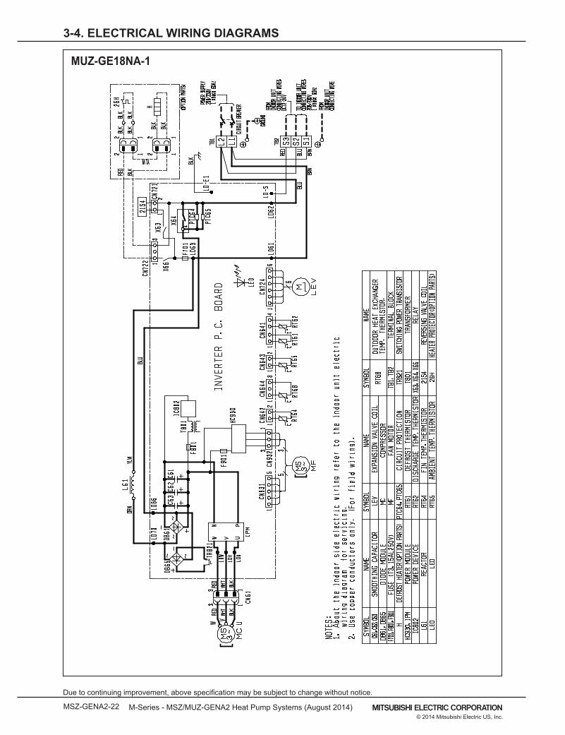
MUZ-GE18NA-1
M-Series - MSZ/MUZ-GENA2 Heat Pump Systems (August 2014) MSZ-GENA2-23© 2014 Mitsubishi Electric US, Inc.
Due to continuing improvement, above specification may be subject to change without notice.
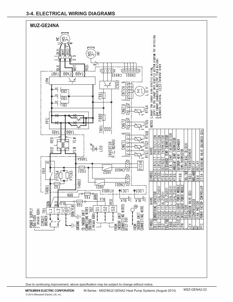
3-4. ELECTRICAL WIRING DIAGRAMS
MUZ-GE24NA

MSZ-GENA2-24 M-Series - MSZ/MUZ-GENA2 Heat Pump Systems (August 2014)
Due to continuing improvement, above specification may be subject to change without notice.
© 2014 Mitsubishi Electric US, Inc.
3-5. REFRIGERANT SYSTEM DIAGRAMS
Indoorheatexchanger Flared connection
Room temperaturethermistorRT11
Flared connection
Refrigerant pipe ø3/8 (MSZ-GE06/09/12NA) ø1/2 (MSZ-GE15/18NA)(with heat insulator)
Refrigerant pipe ø1/4(with heat insulator)
Indoor coil thermistorRT12 (main)
Indoor coil thermistorRT13 (sub)
Refrigerant flow in coolingRefrigerant flow in heating
MSZ-GE24NA
MSZ-GE06NA-8 MSZ-GE09NA-8 MSZ-GE12NA-8 MSZ-GE15NA-8 MSZ-GE18NA-8Unit: inch
Indoorheatexchanger Flared connection
Room temperaturethermistorRT11
Flared connection
Refrigerant pipe ø5/8(with heat insulator)
Refrigerant pipe ø3/8(with heat insulator)
Indoor coil thermistorRT12 (main)
Indoor coil thermistorRT13 (sub)
Refrigerant flow in coolingRefrigerant flow in heating

M-Series - MSZ/MUZ-GENA2 Heat Pump Systems (August 2014) MSZ-GENA2-25© 2014 Mitsubishi Electric US, Inc.
Due to continuing improvement, above specification may be subject to change without notice.
3-5. REFRIGERANT SYSTEM DIAGRAMS
Unit: inchMUZ-GE09NA2
MUZ-GE12NA2 MUZ-GE15NA2
Outdoorheatexchanger
Flared connection
DefrostthermistorRT61(MUZ)
DischargetemperaturethermistorRT62
Flared connection
Stop valve(with strainar)
Stop valve(with service port)
Refrigerant flow in cooling
Compressor
4-way valve
Refrigerant flow in heating (MUZ)
Refrigerant pipe ø3/8(with heat insulator)
Refrigerant pipe ø1/4(with heat insulator)
R.V. coil (MUZ)heating ONcooling OFF
Strainer#100
LEV
Ambient temperature thermistorRT65
Muffler
Capillary tubeO.D. 0.118 × I.D. 0.079 × 9-7/16(ø3.0 × ø2.0 × 240)
Outdoor heatexchangertemperature thermistorRT68
Service port
Service port
Muffler
Outdoorheatexchanger
Flared connection
DefrostthermistorRT61(MUZ)
DischargetemperaturethermistorRT62
Flared connection
Stop valve(with strainar)
Stop valve(with service port)
Refrigerant flow in cooling
Compressor
4-way valve
Refrigerant flow in heating (MUZ)
Refrigerant pipe ø3/8 (GE12NA)Refrigerant pipe ø1/2 (GE15NA)(with heat insulator)
Refrigerant pipe ø1/2(with heat insulator)
R.V. coil (MUZ)heating ONcooling OFF
Strainer#100
Capillary tubeO.D. 0.118 × I.D. 0.071 × 23-5/8(ø3.0 × ø1.8 × 600) (×2)
LEV
Ambient temperature thermistorRT65
Muffler
Capillary tubeO.D. 0.118 × I.D. 0.079 × 9-7/16(ø3.0 × ø2.0 × 240)
Outdoor heatexchangertemperature thermistorRT68Muffler
Service port
Service port

MSZ-GENA2-26 M-Series - MSZ/MUZ-GENA2 Heat Pump Systems (August 2014)
Due to continuing improvement, above specification may be subject to change without notice.
© 2014 Mitsubishi Electric US, Inc.
3-5. REFRIGERANT SYSTEM DIAGRAMS
Unit: inchMUZ-GE18NA-1
Outdoorheatexchanger
Flared connectionDefrostthermistorRT61(MUZ)
DischargetemperaturethermistorRT62
Flared connection
Stop valve(with strainar)
Stop valve(with service port)
Capillary tubeO.D. 0.142 × I.D. 0.094 × 1-31/32(ø3.6×ø2.4×50)
Refrigerant flow in cooling
Compressor
4-way valve
Refrigerant flow in heating (MUZ)
Refrigerant pipe ø1/2(with heat insulator)
Refrigerant pipe ø1/4(with heat insulator)
LEVR.V. coil (MUZ)heating ONcooling OFF
Muffler#100
Receiver
Outdoor heat exchanger temperaturethermistorRT68
AmbienttemperaturethermistorRT65
Strainer#100
Service port
Service port
MUZ-GE24NA
Serviceport
Serviceport
Outdoorheatexchanger
Flared connection
DefrostthermistorRT61(MUZ)
DischargetemperaturethermistorRT62
Flared connection
Stop valve
Stop valve(with service port)
Capillary tubeO.D.0.157 × I.D.0.094× 3-15/16 (ø4.0×ø2.4×100)
Refrigerant flow in cooling
Compressor
4-way valve
Refrigerant flow in heating (MUZ)
Refrigerant pipe ø5/8(with heat insulator)
Refrigerant pipe ø3/8(with heat insulator)
LEVR.V. coil (MUZ)heating ONcooling OFF
Muffler#100
Strainer#100
Outdoor heat exchanger temperaturethermistorRT68
AmbienttemperaturethermistorRT65
Strainer#100

M-Series - MSZ/MUZ-GENA2 Heat Pump Systems (August 2014) MSZ-GENA2-27© 2014 Mitsubishi Electric US, Inc.
Due to continuing improvement, above specification may be subject to change without notice.
3-6. CAPACITY CORRECTION CURVE BY TEMPERATURE
(1) CoolingMUZ-GE09NA2 MUZ-GE12NA2
MUZ-GE15NA2 MUZ-GE18NA
MUZ-GE24NA
710.8
67630.7
0.6
0.5
Indoor intake air WB temperature (°F)
SHF at rating condition = 0.76= 307 CFMAirflow
65 75 85 95 105 115Outdoor intake air DB temperature (°F)
Tota
l pow
er c
onsu
mpt
ion
(kW
)
71
6367
1.21.11.00.90.80.7
Indoor intake air WB temperature (°F)1.3
SHF at rating condition = 0.73= 350 CFMAirflow
65 75 85 95 105 115Outdoor intake air DB temperature (°F)
Tota
l pow
er c
onsu
mpt
ion
(kW
)716763
1.41.31.21.11.00.90.8 Indoor intake air WB temperature (°F)
SHF at rating condition = 0.80= 498 CFMAirflow
65 75 85 95 105 115Outdoor intake air DB temperature (°F)
Tota
l pow
er c
onsu
mpt
ion
(kW
)
716763
2.01.91.81.71.61.51.41.3 Indoor intake air WB temperature (°F)
SHF at rating condition = 0.71= 498 CFMAirflow
65 75 85 95 105 115Outdoor intake air DB temperature (°F)
Tota
l pow
er c
onsu
mpt
ion
(kW
)
716763
65 75 85 95 105 1151.31.41.51.61.71.81.92.02.12.2
Indoor intake air WB temperature (°F)
SHF at rating condition = 0.75= 634 CFMAirflow
Outdoor intake air DB temperature (°F)
Tota
l pow
er c
onsu
mpt
ion
(kW
)

MSZ-GENA2-28 M-Series - MSZ/MUZ-GENA2 Heat Pump Systems (August 2014)
Due to continuing improvement, above specification may be subject to change without notice.
© 2014 Mitsubishi Electric US, Inc.
3-6. CAPACITY CORRECTION CURVE BY TEMPERATURE
(2) HeatingMUZ-GE09NA2 MUZ-GE12NA2
MUZ-GE15NA2
757065
0 10 20 30 40 50 60 700.2
0.4
0.6
0.8
1.0
1.2
Indoor intake air DB temperature (°F)
= 413 CFMAirflow
Outdoor intake air WB temperature (°F)
Tota
l pow
er c
onsu
mpt
ion
(kW
)
757065
0 10 20 30 40 50 60 700.4
0.6
0.8
1.0
1.2
1.4
Indoor intake air DB temperature (°F)
= 413 CFMAirflow
Outdoor intake air WB temperature (°F)
Tota
l pow
er c
onsu
mpt
ion
(kW
)
757065
0 10 20 30 40 50 60 700.5
0.8
1.1
1.4
1.7
2.0
Indoor intake air DB temperature (°F)
= 463 CFMAirflow
Outdoor intake air WB temperature (°F)
Tota
l pow
er c
onsu
mpt
ion
(kW
)
MUZ-GE18NA757065
0 10 20 30 40 50 60 700.60.81.01.21.41.61.82.02.2
Indoor intake air DB temperature (°F)
= 512 CFMAirflow
Outdoor intake air WB temperature (°F)
Tota
l pow
er c
onsu
mpt
ion
(kW
)
MUZ-GE24NA
757065
0 10 20 30 40 50 60 701.0
1.4
1.8
2.2
2.6
3.0
Indoor intake air DB temperature (°F)
= 738 CFMAirflow
Outdoor intake air WB temperature (°F)
Tota
l pow
er c
onsu
mpt
ion
(kW
)

M-Series - MSZ/MUZ-GENA2 Heat Pump Systems (August 2014) MSZ-GENA2-29© 2014 Mitsubishi Electric US, Inc.
Due to continuing improvement, above specification may be subject to change without notice.
3-7. CAPACITY CORRECTION TABLE BY TEMPERATURE
(1) Cooling Capacity
Model
Indoor air
Outdoor intake air DB temperature (˚F)
IWB (˚F)
75 85 95 105 115
TC SHC TPC TC SHC TPC TC SHC TPC TC SHC TPC TC SHC TPC
MUZ-GE09NA2
71 11.0 7.6 0.59 10.3 7.1 0.64 9.7 6.6 0.69 9.0 6.2 0.73 8.3 5.7 0.76
67 10.4 8.6 0.55 9.7 8.0 0.61 9.0 7.4 0.66 8.4 6.9 0.70 7.7 6.3 0.73
63 9.8 9.4 0.53 9.1 8.7 0.58 8.5 8.1 0.63 7.7 7.3 0.67 7.0 6.7 0.70
MUZ-GE12NA2
71 14.7 8.9 0.85 13.7 8.3 0.94 12.9 7.8 1.01 12.0 7.3 1.06 11.0 6.7 1.10
67 13.9 10.3 0.81 13.0 9.6 0.89 12.0 8.9 0.96 11.2 8.3 1.02 10.3 7.6 1.07
63 13.1 11.4 0.77 12.1 10.6 0.85 11.3 9.9 0.92 10.3 9.0 0.98 9.4 8.2 1.02
MUZ-GE15NA2
71 17.2 11.4 0.96 16.0 10.7 1.05 15.1 10.0 1.13 14.0 9.3 1.19 12.9 8.6 1.24
67 16.2 13.0 0.91 15.1 12.1 1.00 14.0 11.2 1.08 13.0 10.4 1.14 12.0 9.6 1.20
63 15.3 14.2 0.86 14.1 13.2 0.96 13.2 12.3 1.03 12.0 11.2 1.10 10.9 10.2 1.14
MUZ-GE18NA-1
71 21.1 12.2 1.46 19.7 11.4 1.60 18.5 10.7 1.72 17.2 9.9 1.81 15.8 9.1 1.89
67 20.0 14.2 1.38 18.6 13.2 1.52 17.2 12.2 1.64 16.0 11.4 1.74 14.7 10.4 1.82
63 18.7 15.8 1.31 17.4 14.7 1.45 16.2 13.6 1.57 14.7 12.4 1.67 13.4 11.3 1.74
MUZ-GE24NA
71 27.6 17.0 1.60 25.8 15.9 1.76 24.2 14.9 1.89 22.5 13.9 1.99 20.7 12.8 2.07
67 26.1 19.6 1.51 24.3 18.2 1.67 22.5 16.9 1.80 20.9 15.7 1.91 19.2 14.4 2.00
63 24.5 21.7 1.44 22.7 20.1 1.59 21.2 18.7 1.72 19.2 17.0 1.84 17.6 15.5 1.91
NOTE: 1. IWB: Intake air wet-bulb temperatureTC: Total Capacity (×103 Btu/h)SHC: Sensible Heat Capacity (×103 Btu/h)TPC: Total Power Consumption (kW)
2. SHC is based on 80˚F of indoor Intake air DB temperature.

MSZ-GENA2-30 M-Series - MSZ/MUZ-GENA2 Heat Pump Systems (August 2014)
Due to continuing improvement, above specification may be subject to change without notice.
© 2014 Mitsubishi Electric US, Inc.
3-7. CAPACITY CORRECTION TABLE BY TEMPERATURE
(2) Heating Capacity
Model
Indoor air
Outdoor intake air WB temperature (˚F)
IDB (˚F)
5 15 25 35 43 45 55
TC TPC TC TPC TC TPC TC TPC TC TPC TC TPC TC TPC
MUZ-GE09NA2
75 4.8 0.45 6.3 0.57 7.9 0.67 9.4 0.74 10.6 0.78 11.0 0.79 12.4 0.82
70 5.2 0.43 6.7 0.55 8.2 0.65 9.6 0.72 10.9 0.76 11.2 0.78 12.7 0.81
65 5.5 0.41 6.9 0.52 8.6 0.63 10.0 0.70 11.2 0.74 11.6 0.75 13.0 0.79
MUZ-GE12NA2
75 6.3 0.69 8.4 0.87 10.4 1.02 12.5 1.14 14.0 1.20 14.5 1.22 16.4 1.26
70 6.8 0.66 8.9 0.84 10.8 1.00 12.7 1.11 14.4 1.17 14.8 1.19 16.8 1.24
65 7.2 0.63 9.1 0.81 11.3 0.97 13.2 1.08 14.8 1.14 15.3 1.16 17.1 1.22
MUZ-GE15NA2
75 7.9 0.63 10.4 0.79 13.1 0.93 1.56 1.03 17.6 1.09 18.1 1.10 20.5 1.14
70 8.6 0.60 11.1 0.76 13.5 0.91 15.9 1.01 18.0 1.06 18.5 1.08 21.0 1.12
65 9.0 0.57 11.3 0.73 14.1 0.87 16.5 0.98 18.5 1.03 19.1 1.05 21.4 1.10
MUZ-GE18NA
75 9.1 0.64 11.9 0.81 14.9 0.95 17.8 1.06 20.1 1.12 20.7 1.13 23.5 1.18
70 9.8 0.62 12.7 0.78 15.5 0.93 18.2 1.04 20.6 1.09 21.2 1.11 24.0 1.16
65 10.3 0.59 13.0 0.75 16.2 0.90 18.8 1.01 21.2 1.06 21.8 1.08 24.5 1.13
MUZ-GE24NA
75 12.1 1.38 16.0 1.74 20.0 2.05 23.9 2.28 26.9 2.40 27.7 2.43 31.5 2.53
70 13.1 1.32 17.0 1.68 20.7 2.00 24.4 2.22 27.6 2.34 28.4 2.39 32.2 2.48
65 13.8 1.26 17.4 1.61 21.7 1.93 25.3 2.16 28.4 2.28 29.3 2.32 32.8 2.43
NOTE: 1. IDB :Intake air dry-bulb temperatureTC: Total Capacity (x103 Btu/h)TPC: Total Power Consumption (kW)
2. Above data is for heating operation without any frost.
How to operate with fixed operational frequency of the compressor.1. Press the EMERGENCY OPERATION switch on the front of the indoor unit, and select either EMERGENCY COOL mode or EMERGENCY
HEAT mode before starting to operate the air conditioner.2. The compressor starts with operational frequency.3. The fan speed of the indoor unit is High.4. This operation continues for 30 minutes.
5. In order to release this operation, press the EMERGENCY OPERATION switch twice or once, or press any button on the remote controller.

M-Series - MSZ/MUZ-GENA2 Heat Pump Systems (August 2014) MSZ-GENA2-31© 2014 Mitsubishi Electric US, Inc.
Due to continuing improvement, above specification may be subject to change without notice.
3-7. CAPACITY CORRECTION TABLE BY TEMPERATURE
DUE TO CONTINUING RESEARCH AND PRODUCT IMPROVEMENT,
SPECIFICATIONS AND DATA ARE STILL UNDER REVIEW

MSZ-GENA2-32 M-Series - MSZ/MUZ-GENA2 Heat Pump Systems (August 2014)
Due to continuing improvement, above specification may be subject to change without notice.
© 2014 Mitsubishi Electric US, Inc.
3-8. CAPACITY CORRECTION CURVE BY REFRIGERANT PIPING LENGTH
DUE TO CONTINUING RESEARCH AND PRODUCT IMPROVEMENT,
SPECIFICATIONS AND DATA ARE STILL UNDER REVIEW

M-Series - MSZ/MUZ-GENA2 Heat Pump Systems (August 2014) MSZ-GENA2-33© 2014 Mitsubishi Electric US, Inc.
Due to continuing improvement, above specification may be subject to change without notice.
3-9. CAPACITY CORRECTION TABLE BY REFRIGERANT PIPING LENGTH
Refrigerant piping length (one way: ft.)
25 (std.) 40 65 100
MUZ-GE09NA2MUZ-GE12NA2 MUZ-GE15NA2 MUZ-GE18NA-1
1.0 0.954 0.878 -
MUZ-GE24NA 1.0 0.954 0.878 0.771
Model
Refrigerant piping: ft Piping size: in.
Additional piping
Max. lengthA
Additional piping
Max. heightB
Gas Liquid
Outsidediameter
Outsidediameter
MUZ-GE09NA2 65 40 3/8 1/4
MUZ-GE12NA2 MUZ-GE15NA2 65 40 1/2 1/4
MUZ-GE18NA-1 100 50 1/2 3/8
MUZ-GE24NA 100 50 5/8 3/8
(2) Maximum Refrigerant Piping Length & Maximum Height Difference
Max. Height difference B
Additional PipingMax. length A
Indoorunit
Outdoor unit
(1) Cooling Capacity Correction

MSZ-GENA2-34 M-Series - MSZ/MUZ-GENA2 Heat Pump Systems (August 2014)
Due to continuing improvement, above specification may be subject to change without notice.
© 2014 Mitsubishi Electric US, Inc.
3-9. CAPACITY CORRECTION TABLE BY REFRIGERANT PIPING LENGTH
DUE TO CONTINUING RESEARCH AND PRODUCT IMPROVEMENT,
SPECIFICATIONS AND DATA ARE STILL UNDER REVIEW

M-Series - MSZ/MUZ-GENA2 Heat Pump Systems (August 2014) MSZ-GENA2-35© 2014 Mitsubishi Electric US, Inc.
Due to continuing improvement, above specification may be subject to change without notice.
3-10. CHARGE CALCULATIONS
Model Outdoor unit precharged
Refrigerant piping length (one way): ft.
25ft 30ft 40ft 50ft 60ft 65ft
MUZ-GE09NA2 1 lb. 12 oz.
0 1.62 4.86 8.10 11.34 12.96MUZ-GE12NA22 lb. 9 oz.
MUZ-GE15NA2 NOTE: Calculation: X oz. = 1.62/5 oz./ft (Refrigerant piping length (ft) - 25)
Model Outdoor unit precharged
Refrigerant piping length (one way): ft.
25 30 40 50 60 70 80 90 100
MUZ-GE18NA-1 3 lb. 7 oz. 0 1.08 3.24 5.40 7.56 9.72 11.88 14.04 16.20
NOTE: Calculation: X oz. = 1.08/5 oz./ft (Refrigerant piping length (ft) - 25) NOTE: Refrigerant piping exceeding 33 ft. requires additional refrigerant charge according to the calculation.
ModelOutdoor
unit precharged
Refrigerant piping length (one way): ft.
33 40 50 60 70 80 90 100
MUZ-GE24NA 4 lb. 3 oz. 0 4.14 10.06 15.98 21.90 27.82 33.74 39.66 NOTE: Calculation: X oz. = 2.96/5 oz./ft (Refrigerant piping length (ft) - 33)
(1) Additional Refrigerant Charge (R410a: Oz.)NOTE: Refrigerant piping exceeding 25 ft. requires additional refrigerant charge according to the calcualation.

MSZ-GENA2-36 M-Series - MSZ/MUZ-GENA2 Heat Pump Systems (August 2014)
Due to continuing improvement, above specification may be subject to change without notice.
© 2014 Mitsubishi Electric US, Inc.
3-11. AIR FLOW DATA
● The air coverage is the figure up to the position where the air speed is 1 ft./s., when air is blown out horizontally from the unit properly at the High speed position.
The coverage should be used only as a general guideline since it varies according to the size of the room and furniture arranged inside the room.
Model name Mode Function Airflow(CFM)
Air speed(ft./s.) Coverage (ft.)
MSZ-GE06NA-8
HEAT Dry 406 20.6 29.5
COOLDry 321 16.3 23.5
Wet 286 14.5 21.0
MSZ-GE09NA-8
HEAT Dry 406 20.6 29.5
COOLDry 321 16.3 23.5
Wet 286 14.5 21.0
MSZ-GE12NA-8
HEAT Dry 406 20.6 29.5
COOLDry 321 16.3 23.5
Wet 286 14.5 21.0
MSZ-GE15NA-8
HEAT Dry 463 23.4 33.5
COOLDry 420 21.3 30.5
Wet 385 19.5 28.0
MSZ-GE18NA-8
HEAT Dry 512 25.9 36.9
COOLDry 420 21.3 30.5
Wet 385 19.5 28.0
MSZ-GE24NA
HEAT Dry 738 18.0 36.9
COOLDry 738 18.0 36.9
Wet 661 16.1 31.9
Outlet Air Speed And Coverage

M-Series - MSZ/MUZ-GENA2 Heat Pump Systems (August 2014) MSZ-GENA2-37© 2014 Mitsubishi Electric US, Inc.
Due to continuing improvement, above specification may be subject to change without notice.
3-12. SOUND PRESSURE LEVELS
NOTE: The sound level is measured in an anechoic room where echoes are few, when compressor stops. The soundmay be bigger than displayed level under actual installation condition by surrounding echoes. The sound levelcan be higher by about 2 dB than the displayed level during cooling and heating operation.
90
80
70
60
50
40
30
20
1063 125 250 500 1000 2000 4000 8000
NC-60
NC-50
NC-40
NC-30
NC-20
NC-70
BAND CENTER FREQUENCIES, Hz
APPROXIMATETHRESHOLD OF HEARING FORCONTINUOUSNOISE
COOLING(SHi)
SPL(dB(A)) LINE
HEATING(SHi)
43
43
OC
TAVE
BA
ND
SO
UN
D P
RES
SUR
E LE
VEL,
dB
(0 d
B =
0.0
002
µbar
)MSZ-GE06NAMSZ-GE09NA
90
80
70
60
50
40
30
20
1063 125 250 500 1000 2000 4000 8000
NC-60
NC-50
NC-40
NC-30
NC-20
NC-70
BAND CENTER FREQUENCIES, Hz
SPL(dB(A)) LINE
45
43
OC
TAVE
BA
ND
SO
UN
D P
RES
SUR
E LE
VEL,
dB
(0 d
B =
0.0
002
µbar
)
MSZ-GE12NA
SPL(dB(A)) LINE
49
48
90
80
70
60
50
40
30
20
1063 125 250 500 1000 2000 4000 8000
NC-60
NC-50
NC-40
NC-30
NC-20
NC-70
BAND CENTER FREQUENCIES, Hz
OC
TAVE
BA
ND
SO
UN
D P
RES
SUR
E LE
VEL,
dB
(0 d
B =
0.0
002
µbar
)
MSZ-GE18NA
APPROXIMATETHRESHOLD OF HEARING FORCONTINUOUSNOISE
APPROXIMATETHRESHOLD OF HEARING FORCONTINUOUSNOISE
90
80
70
60
50
40
30
20
1063 125 250 500 1000 2000 4000 8000
NC-60
NC-50
NC-40
NC-30
NC-20
NC-70
BAND CENTER FREQUENCIES, Hz
SPL(dB(A)) LINE
49
46
OC
TAVE
BA
ND
SO
UN
D P
RES
SUR
E LE
VEL,
dB
(0 d
B =
0.0
002
µbar
)
MSZ-GE15NA
APPROXIMATETHRESHOLD OF HEARING FORCONTINUOUSNOISE
NOTCH
COOLING(SHi)
HEATING(SHi)
NOTCH
COOLING(SHi)
HEATING(SHi)
NOTCHCOOLING(SHi)
HEATING(SHi)
NOTCH
MSZ-GE06NA-8 MSZ-GE09NA-8
MSZ-GE12NA-8
MSZ-GE15NA-8 MSZ-GE18NA-8
(1) Indoor Unit

MSZ-GENA2-38 M-Series - MSZ/MUZ-GENA2 Heat Pump Systems (August 2014)
Due to continuing improvement, above specification may be subject to change without notice.
© 2014 Mitsubishi Electric US, Inc.
3-12. SOUND PRESSURE LEVELS
NOTE: The sound level is measured in an anechoic room where echoes are few, when compressor stops. The soundmay be bigger than displayed level under actual installation condition by surrounding echoes. The sound levelcan be higher by about 2 dB than the displayed level during cooling and heating operation.
90
80
70
60
50
40
30
20
1063 125 250 500 1000 2000 4000 8000
NC-60
NC-50
NC-40
NC-30
NC-20
NC-70
BAND CENTER FREQUENCIES, Hz
APPROXIMATETHRESHOLD OF HEARING FORCONTINUOUSNOISE
SPL(dB(A)) LINE
53
–
OC
TAVE
BA
ND
SO
UN
D P
RES
SUR
E LE
VEL,
dB
(0 d
B =
0.0
002
µbar
)MSZ-GE24NA
90
80
70
60
50
40
30
20
1063 125 250 500 1000 2000 4000 8000
NC-60
NC-50
NC-40
NC-30
NC-20
NC-70
BAND CENTER FREQUENCIES, Hz
SPL(dB(A)) LINE
43
–
OC
TAVE
BA
ND
SO
UN
D P
RES
SUR
E LE
VEL,
dB
(0 d
B =
0.0
002
µbar
)
MSY-GE09NA
SPL(dB(A)) LINE
49
90
80
70
60
50
40
30
20
1063 125 250 500 1000 2000 4000 8000
NC-60
NC-50
NC-40
NC-30
NC-20
NC-70
BAND CENTER FREQUENCIES, Hz
OC
TAVE
BA
ND
SO
UN
D P
RES
SUR
E LE
VEL,
dB
(0 d
B =
0.0
002
µbar
)
MSY-GE15NA
APPROXIMATETHRESHOLD OF HEARING FORCONTINUOUSNOISE
APPROXIMATETHRESHOLD OF HEARING FORCONTINUOUSNOISE
90
80
70
60
50
40
30
20
1063 125 250 500 1000 2000 4000 8000
NC-60
NC-50
NC-40
NC-30
NC-20
NC-70
BAND CENTER FREQUENCIES, Hz
SPL(dB(A)) LINE
45
–
53
OC
TAVE
BA
ND
SO
UN
D P
RES
SUR
E LE
VEL,
dB
(0 d
B =
0.0
002
µbar
)
MSY-GE12NA
APPROXIMATETHRESHOLD OF HEARING FORCONTINUOUSNOISE
COOLING(Rated)
HEATING(Rated)
NOTCH
COOLING(SHi)
HEATING(SHi)
NOTCH
COOLING(SHi)
HEATING(SHi)
NOTCHCOOLING(SHi)
HEATING(SHi)
NOTCH
MSZ-GE24NA
(2) Outdoor Unit
90
80
70
60
50
40
30
20
1063 125 250 500 1000 2000 4000 8000
NC-60
NC-50
NC-40
NC-30
NC-20
NC-70
BAND CENTER FREQUENCIES, Hz
APPROXIMATETHRESHOLD OF HEARING FORCONTINUOUSNOISE
SPL(dB(A)) LINE
COOLING
NOTCH
HEATING
46
50
OC
TAVE
BA
ND
SO
UN
D P
RES
SUR
E LE
VEL,
dB
(0 d
B =
0.0
002
µbar
)
MUZ-GE09NA2MUZ-GE09NAH2
90
80
70
60
50
40
30
20
1063 125 250 500 1000 2000 4000 8000
NC-60
NC-50
NC-40
NC-30
NC-20
NC-70
BAND CENTER FREQUENCIES, Hz
SPL(dB(A)) LINE
49
51
OC
TAVE
BA
ND
SO
UN
D P
RES
SUR
E LE
VEL,
dB
(0 d
B =
0.0
002
µbar
)
MUZ-GE12NA2MUZ-GE12NAH2
SPL(dB(A)) LINE
54
56
90
80
70
60
50
40
30
20
1063 125 250 500 1000 2000 4000 8000
NC-60
NC-50
NC-40
NC-30
NC-20
NC-70
BAND CENTER FREQUENCIES, Hz
OC
TAVE
BA
ND
SO
UN
D P
RES
SUR
E LE
VEL,
dB
(0 d
B =
0.0
002
µbar
)
MUZ-GE18NAMUZ-GE18NAH
APPROXIMATETHRESHOLD OF HEARING FORCONTINUOUSNOISE
APPROXIMATETHRESHOLD OF HEARING FORCONTINUOUSNOISE
90
80
70
60
50
40
30
20
1063 125 250 500 1000 2000 4000 8000
NC-60
NC-50
NC-40
NC-30
NC-20
NC-70
BAND CENTER FREQUENCIES, Hz
SPL(dB(A)) LINE
49
51
OC
TAVE
BA
ND
SO
UN
D P
RES
SUR
E LE
VEL,
dB
(0 d
B =
0.0
002
µbar
)
MUZ-GE15NA2MUZ-GE15NAH2
APPROXIMATETHRESHOLD OF HEARING FORCONTINUOUSNOISE
COOLING
NOTCH
HEATING
COOLING
NOTCH
HEATING
COOLING
NOTCH
HEATING
MUZ-GE09NA2 MUZ-GE12NA2
NOTE: The sound level is measured in an anechoic room where echoes are few, when compressor stops. The soundmay be bigger than displayed level under actual installation condition by surrounding echoes. The sound levelcan be higher by about 2 dB than the displayed level during cooling and heating operation.
WALL
UNIT
31-1/2 inch (0.8m)
39-3/8 inch (1m)
MICROPHONE
90
80
70
60
50
40
30
20
1063 125 250 500 1000 2000 4000 8000
NC-60
NC-50
NC-40
NC-30
NC-20
NC-70
BAND CENTER FREQUENCIES, Hz
APPROXIMATETHRESHOLD OF HEARING FORCONTINUOUSNOISE
SPL(dB(A)) LINE
53
OC
TAVE
BA
ND
SO
UN
D P
RES
SUR
E LE
VEL,
dB
(0 d
B =
0.0
002
µbar
)
MSZ-FE18NA
90
80
70
60
50
40
30
20
1063 125 250 500 1000 2000 4000 8000
NC-60
NC-50
NC-40
NC-30
NC-20
NC-70
BAND CENTER FREQUENCIES, Hz
SPL(dB(A)) LINE
49
OC
TAVE
BA
ND
SO
UN
D P
RES
SUR
E LE
VEL,
dB
(0 d
B =
0.0
002
µbar
)
MSZ-D30NAMSZ-D36NAMSY-D30NAMSY-D36NA
APPROXIMATETHRESHOLD OF HEARING FORCONTINUOUSNOISE
53
COOLING(Rated)
HEATING(Rated)
NOTCH
COOLING(Hi)
HEATING(Hi)
NOTCH
● NOTE:The sound level is measured in an anechoic room where echoes are few,when compressor stops.The sound may be bigger than displayed level under actual installation condition by surrounding echoes.The sound level can be higher by about 2 dB than the displayed level during cooling and heating operation.

M-Series - MSZ/MUZ-GENA2 Heat Pump Systems (August 2014) MSZ-GENA2-39© 2014 Mitsubishi Electric US, Inc.
Due to continuing improvement, above specification may be subject to change without notice.
3-12. SOUND PRESSURE LEVELS
3-12. SOUND PRESSURE LEVELS
90
80
70
60
50
40
30
20
1063 125 250 500 1000 2000 4000 8000
NC-60
NC-50
NC-40
NC-30
NC-20
NC-70
BAND CENTER FREQUENCIES, Hz
APPROXIMATETHRESHOLD OF HEARING FORCONTINUOUSNOISE
SPL(dB(A)) LINE
COOLING
NOTCH
HEATING
46
50
OC
TAVE
BA
ND
SO
UN
D P
RES
SUR
E LE
VEL,
dB
(0 d
B =
0.0
002
µbar
)
MUZ-GE09NA2MUZ-GE09NAH2
90
80
70
60
50
40
30
20
1063 125 250 500 1000 2000 4000 8000
NC-60
NC-50
NC-40
NC-30
NC-20
NC-70
BAND CENTER FREQUENCIES, Hz
SPL(dB(A)) LINE
49
51
OC
TAVE
BA
ND
SO
UN
D P
RES
SUR
E LE
VEL,
dB
(0 d
B =
0.0
002
µbar
)
MUZ-GE12NA2MUZ-GE12NAH2
SPL(dB(A)) LINE
54
56
90
80
70
60
50
40
30
20
1063 125 250 500 1000 2000 4000 8000
NC-60
NC-50
NC-40
NC-30
NC-20
NC-70
BAND CENTER FREQUENCIES, HzO
CTA
VE B
AN
D S
OU
ND
PR
ESSU
RE
LEVE
L, d
B (0
dB
= 0
.000
2 µb
ar)
MUZ-GE18NAMUZ-GE18NAH
APPROXIMATETHRESHOLD OF HEARING FORCONTINUOUSNOISE
APPROXIMATETHRESHOLD OF HEARING FORCONTINUOUSNOISE
90
80
70
60
50
40
30
20
1063 125 250 500 1000 2000 4000 8000
NC-60
NC-50
NC-40
NC-30
NC-20
NC-70
BAND CENTER FREQUENCIES, Hz
SPL(dB(A)) LINE
49
51
OC
TAVE
BA
ND
SO
UN
D P
RES
SUR
E LE
VEL,
dB
(0 d
B =
0.0
002
µbar
)MUZ-GE15NA2MUZ-GE15NAH2
APPROXIMATETHRESHOLD OF HEARING FORCONTINUOUSNOISE
COOLING
NOTCH
HEATING
COOLING
NOTCH
HEATING
COOLING
NOTCH
HEATING
MUZ-GE15NA2
UNIT
39-3/8 inch (1m)MICROPHONE
90
80
70
60
50
40
30
20
1063 125 250 500 1000 2000 4000 8000
NC-60
NC-50
NC-40
NC-30
NC-20
NC-70
BAND CENTER FREQUENCIES, Hz
APPROXIMATETHRESHOLD OF HEARING FORCONTINUOUSNOISE
SPL(dB(A)) LINE
55
OC
TAVE
BA
ND
SO
UN
D P
RES
SUR
E LE
VEL,
dB
(0 d
B =
0.0
002
µbar
)
MUZ-FE18NA
90
80
70
60
50
40
30
20
1063 125 250 500 1000 2000 4000 8000
NC-60
NC-50
NC-40
NC-30
NC-20
NC-70
BAND CENTER FREQUENCIES, Hz
SPL(dB(A)) LINE
55
OC
TAVE
BA
ND
SO
UN
D P
RES
SUR
E LE
VEL,
dB
(0 d
B =
0.0
002
µbar
)
MUZ-D30NAMUY-D30NA
APPROXIMATETHRESHOLD OF HEARING FORCONTINUOUSNOISE
90
80
70
60
50
40
30
20
1063 125 250 500 1000 2000 4000 8000
NC-60
NC-50
NC-40
NC-30
NC-20
NC-70
BAND CENTER FREQUENCIES, Hz
SPL(dB(A)) LINE
56
OC
TAVE
BA
ND
SO
UN
D P
RES
SUR
E LE
VEL,
dB
(0 d
B =
0.0
002
µbar
)
MUZ-D36NAMUY-D36NA
APPROXIMATETHRESHOLD OF HEARING FORCONTINUOUSNOISE
57
55 57
COOLING
NOTCH
HEATING
COOLING
NOTCH
HEATING
COOLING
NOTCH
HEATING
90
80
70
60
50
40
30
20
1063 125 250 500 1000 2000 4000 8000
NC-60
NC-50
NC-40
NC-30
NC-20
NC-70
BAND CENTER FREQUENCIES, Hz
APPROXIMATETHRESHOLD OF HEARING FORCONTINUOUSNOISE
SPL(dB(A)) LINE
55
–
OC
TAVE
BA
ND
SO
UN
D P
RES
SUR
E LE
VEL,
dB
(0 d
B =
0.0
002
µbar
)
MUZ-GE24NA
90
80
70
60
50
40
30
20
1063 125 250 500 1000 2000 4000 8000
NC-60
NC-50
NC-40
NC-30
NC-20
NC-70
BAND CENTER FREQUENCIES, Hz
SPL(dB(A)) LINE
46
–
OC
TAVE
BA
ND
SO
UN
D P
RES
SUR
E LE
VEL,
dB
(0 d
B =
0.0
002
µbar
)
MUY-GE09NA2
SPL(dB(A)) LINE
49
90
80
70
60
50
40
30
20
1063 125 250 500 1000 2000 4000 8000
NC-60
NC-50
NC-40
NC-30
NC-20
NC-70
BAND CENTER FREQUENCIES, Hz
OC
TAVE
BA
ND
SO
UN
D P
RES
SUR
E LE
VEL,
dB
(0 d
B =
0.0
002
µbar
)
MUY-GE15NA2
APPROXIMATETHRESHOLD OF HEARING FORCONTINUOUSNOISE
APPROXIMATETHRESHOLD OF HEARING FORCONTINUOUSNOISE
90
80
70
60
50
40
30
20
1063 125 250 500 1000 2000 4000 8000
NC-60
NC-50
NC-40
NC-30
NC-20
NC-70
BAND CENTER FREQUENCIES, Hz
SPL(dB(A)) LINE
49
–
55
OC
TAVE
BA
ND
SO
UN
D P
RES
SUR
E LE
VEL,
dB
(0 d
B =
0.0
002
µbar
)
MUY-GE12NA2
APPROXIMATETHRESHOLD OF HEARING FORCONTINUOUSNOISE
COOLING
NOTCH
HEATING
COOLING
NOTCH
HEATING
COOLING
NOTCH
HEATING
COOLING
NOTCH
HEATING
MUZ-GE24NA
90
80
70
60
50
40
30
20
1063 125 250 500 1000 2000 4000 8000
NC-60
NC-50
NC-40
NC-30
NC-20
NC-70
BAND CENTER FREQUENCIES, Hz
APPROXIMATETHRESHOLD OF HEARING FORCONTINUOUSNOISE
SPL(dB(A)) LINE
COOLING
NOTCH
HEATING
46
50
OC
TAVE
BA
ND
SO
UN
D P
RES
SUR
E LE
VEL,
dB
(0 d
B =
0.0
002
µbar
)
MUZ-GE09NA2MUZ-GE09NAH2
90
80
70
60
50
40
30
20
1063 125 250 500 1000 2000 4000 8000
NC-60
NC-50
NC-40
NC-30
NC-20
NC-70
BAND CENTER FREQUENCIES, Hz
SPL(dB(A)) LINE
49
51
OC
TAVE
BA
ND
SO
UN
D P
RES
SUR
E LE
VEL,
dB
(0 d
B =
0.0
002
µbar
)MUZ-GE12NA2MUZ-GE12NAH2
SPL(dB(A)) LINE
54
56
90
80
70
60
50
40
30
20
1063 125 250 500 1000 2000 4000 8000
NC-60
NC-50
NC-40
NC-30
NC-20
NC-70
BAND CENTER FREQUENCIES, Hz
OC
TAVE
BA
ND
SO
UN
D P
RES
SUR
E LE
VEL,
dB
(0 d
B =
0.0
002
µbar
)
MUZ-GE18NAMUZ-GE18NAH
APPROXIMATETHRESHOLD OF HEARING FORCONTINUOUSNOISE
APPROXIMATETHRESHOLD OF HEARING FORCONTINUOUSNOISE
90
80
70
60
50
40
30
20
1063 125 250 500 1000 2000 4000 8000
NC-60
NC-50
NC-40
NC-30
NC-20
NC-70
BAND CENTER FREQUENCIES, Hz
SPL(dB(A)) LINE
49
51
OC
TAVE
BA
ND
SO
UN
D P
RES
SUR
E LE
VEL,
dB
(0 d
B =
0.0
002
µbar
)
MUZ-GE15NA2MUZ-GE15NAH2
APPROXIMATETHRESHOLD OF HEARING FORCONTINUOUSNOISE
COOLING
NOTCH
HEATING
COOLING
NOTCH
HEATING
COOLING
NOTCH
HEATING
MUZ-GE18NA-1

MSZ-GENA2-40 M-Series - MSZ/MUZ-GENA2 Heat Pump Systems (August 2014)
Due to continuing improvement, above specification may be subject to change without notice.
© 2014 Mitsubishi Electric US, Inc.
3-13. STANDARD OPERATION RANGE
(2) OPERATION
Mode Condition
Intake air temperature (°F)
Indoor Outdoor
DB WB DB WB
Cooling
Standard temperature 80 67 95 —
Maximum temperature 90 73 115 —
Minimum temperature 67 57 14 —
Maximum humidity 78 % —
Heating(MUZ)
Standard temperature 70 60 47 43
Maximum temperature 80 67 75 65
Minimum temperature 70 60 -4 -5
OPERATING RANGE(1) POWER SUPPLY
Rated voltage Guaranteed voltage (V)
Outdoor unit 208/230 V 1 phase 60 Hz
Min. 187 208 230 Max. 253

M-Series - MSZ/MUZ-GENA2 Heat Pump Systems (August 2014) MSZ-GENA2-41© 2014 Mitsubishi Electric US, Inc.
Due to continuing improvement, above specification may be subject to change without notice.
3-14. MAXIMUM HEATING CAPACITY IN LOW AMBIENT TEMPERATURE
HEATING CAPACITY-13.0 -4.0 5.0 14.0 23.0 32.0 41.0 50.0 69.8
0%
20%
40%
60%
80%
100%
120%
-15 -5 5 15 25 35 45
Outdoor Temperature Degrees (oF)
% H
eatin
g C
apac
ity
Outdoor Temperature Degrees (oF)% Heating Capacity 35% 50% 65% 79% 91% 100% 100% 100% 100%
HEATING CAPACITY-13.0 -4.0 5.0 14.0 23.0 32.0 41.0 50.0 69.8
0%
20%
40%
60%
80%
100%
120%
-15 -5 5 15 25 35 45
Outdoor Temperature Degrees (oF)
% H
eatin
g C
apac
ity
36% 50% 64% 78% 88% 97% 100% 100% 100%Outdoor Temperature Degrees (oF)% Heating Capacity
MUZ-GE09NA2
MUZ-GE12NA2

MSZ-GENA2-42 M-Series - MSZ/MUZ-GENA2 Heat Pump Systems (August 2014)
Due to continuing improvement, above specification may be subject to change without notice.
© 2014 Mitsubishi Electric US, Inc.
3-14. MAXIMUM HEATING CAPACITY IN LOW AMBIENT TEMPERATURE
HEATING CAPACITY-13.0 -4.0 5.0 14.0 23.0 32.0 41.0 50.0 69.8
0%
20%
40%
60%
80%
100%
120%
-15 -5 5 15 25 35 45
Outdoor Temperature Degrees (oF)
% H
eatin
g C
apac
ity
39% 55% 70% 85% 92% 96% 100% 100% 100%Outdoor Temperature Degrees (oF)% Heating Capacity
HEATING CAPACITY-13.0 -4.0 5.0 14.0 23.0 32.0 41.0 50.0 69.8
0%
20%
40%
60%
80%
100%
120%
-15 -5 5 15 25 35 45
Outdoor Temperature Degrees (oF)
% H
eatin
g C
apac
ity
34% 48% 63% 77% 88% 97% 100% 100% 100%Outdoor Temperature Degrees (oF)% Heating Capacity
MUZ-GE15NA2
MUZ-GE18NA

M-Series - MSZ/MUZ-GENA2 Heat Pump Systems (August 2014) MSZ-GENA2-43© 2014 Mitsubishi Electric US, Inc.
Due to continuing improvement, above specification may be subject to change without notice.
3-14. MAXIMUM HEATING CAPACITY IN LOW AMBIENT TEMPERATURE
MUZ-GE24NAMUZ-GE24NA MUZ-GE24NA MUZ-GE24NA MUZ-GE24NA
5000
10000
15000
20000
25000
30000
35000
40000
45000
50000Hea
ting M
ax C
apaci
ty (
Btu
/h)
HEATING MAX CAPACITY
DB (oF) -13.0 -4.0 5.0 14.0 23.0 32.0 41.0 50.0 69.8
Q (Btu/h) 15010 18422 21835 25248 27047 28153 29259 38899 46406W(kW) 2.85 3.00 3.15 3.25 3.35 3.50 3.60 3.70 3.80COP 5.27 6.14 6.93 7.77 8.07 8.04 8.13 10.51 12.21
0
5000
10000
-15 -5 5 15 25 35 45 55 65 75
DB (oF)

MSZ-GENA2-44 M-Series - MSZ/MUZ-GENA2 Heat Pump Systems (August 2014)
Due to continuing improvement, above specification may be subject to change without notice.
© 2014 Mitsubishi Electric US, Inc.
(1) Indoor Unit
Part Number Descriptions Applicable model
C13-103 Blue Diamond Sensor Extension Cable - 15 Ft.
All Models
DPLS1 Drain Pan Level Sensor/Control for indoor unit shut off to prevent Drain Pan Overflow
MAC-2310FT-E Anti-Allergy Enzyme Filter (qty of 2) GE24
MAC-308FT-E Platinum Catalyst Deodorizing Filter GE06,09,12,15,18
MAC-333IF-E
System Control Interface - MA, Contact terminal, and
M-NET Control Adapter, Supplemental heat and humidifier
adaptor
All Models
MAC-408FT-E Anti-Allergy Enzyme Filter (qty of 2) GE06,09,12,15,18
MCCH1 Portable Central Controller (PCC) - controls up to 16 RedLINK Zones - requires an MHK1 on each indoor unit
All Models
MHK1 Wireless wall-mounted remote controller (MRCH1) with a signal receiver (MIFH1) and cable (MRC1) all in one kit
MOS1 Outdoor Air Sensor - reads both outside temperature and humidity displayed on MRCH1 and MCCH1 if installed
PAC-YT53CRAU Simple MA Remote Controller (requires MAC-333IF-E interface for MSY/Z and MFZ indoor units)
PAR-31MAA
Wall mounted, hard wired, multi-functional controller: used
specifically for grouping (up to 16 units), twinning, lead/lag,
and 7 day programmable applications
(requires MAC-333IF-E interface for MSY/Z and MFZ indoor
units)
RCMKP1CBLockdown Bracket for wireless, hand-held, remote
controllers
3-15. ACCESSORIES

M-Series - MSZ/MUZ-GENA2 Heat Pump Systems (August 2014) MSZ-GENA2-45© 2014 Mitsubishi Electric US, Inc.
Due to continuing improvement, above specification may be subject to change without notice.
(1) Indoor Unit Cont.
Part Number Descriptions Applicable model
SI30-115 Mini-Condensation pump - 115 volt application
All Models
SI30-230 Mini-Condensation pump - 230 volt application
TAZ-MS303
3-Pole Disconnect Switch 30 Amps 600 volts rated for
interupting power supply at/near indoor unit - fits 2 X 4 utility
box
X87-721Advanced Blue Diamond Mini-Condensation pump w/
Resevoir & Sensor - 208/230 volt application
MLS143812T-15
Diamondback
Linesets
1/4 x 3/8 x 15' / 1/2" Twin-Tube Insulation
GE09,12
MLS143812T-30 1/4 x 3/8 x 30' / 1/2" Twin-Tube Insulation
MLS143812T-50 1/4 x 3/8 x 50' / 1/2" Twin-Tube Insulation
MLS143812T-65 1/4 x 3/8 x 65' / 1/2" Twin-Tube Insulation
MLS141212T-15 1/4 x 1/2 x 15' / 1/2" Twin-Tube Insulation
GE15,18
MLS141212T-30 1/4 x 1/2 x 30' / 1/2" Twin-Tube Insulation
MLS141212T-50 1/4 x 1/2 x 50' / 1/2" Twin-Tube Insulation
MLS141212T-65 1/4 x 1/2 x 65' / 1/2" Twin-Tube Insulation
MLS141212T-100 1/4 x 1/2 x 100' / 1/2" Twin-Tube Insulation
3-15. ACCESSORIES

MSZ-GENA2-46 M-Series - MSZ/MUZ-GENA2 Heat Pump Systems (August 2014)
Due to continuing improvement, above specification may be subject to change without notice.
© 2014 Mitsubishi Electric US, Inc.
(1) Indoor Unit Cont.
Part Number Descriptions Applicable model
MPLS385812T-10
Diamondback
Linesets
3/8 x 5/8 x 10' / 1/2" Twin-Tube Insulation
GE24
MPLS385812T-15 3/8 x 5/8 x 15' / 1/2" Twin-Tube Insulation
MPLS385812T-30 3/8 x 5/8 x 30' / 1/2" Twin-Tube Insulation
MPLS385812T-50 3/8 x 5/8 x 50' / 1/2" Twin-Tube Insulation
MPLS385812T-65 3/8 x 5/8 x 65' / 1/2" Twin-Tube Insulation
MPLS385812T-100 3/8 x 5/8 x 100' / 1/2" Twin-Tube Insulation
3-15. ACCESSORIES

M-Series - MSZ/MUZ-GENA2 Heat Pump Systems (August 2014) MSZ-GENA2-47© 2014 Mitsubishi Electric US, Inc.
Due to continuing improvement, above specification may be subject to change without notice.
3-15. ACCESSORIES
(2) Outdoor Unit
Part Number Descriptions Applicable model
CWMB1 4 piece ( 1 pair) condensing unit wall mounting brackets - painted steel
All Models
DSD-400P Outdoor Unit 3-1/4 inch Mounting Base (Pair) - Plastic
MAC-640BH-U Outdoor Unit Drain Pan Heater used during defrost cycle GE09,12,15
MAC-641BH-U Outdoor Unit Drain Pan Heater used during defrost cycle GE18
MAC-642BH-U Outdoor Unit Drain Pan Heater used during defrost cycle GE24
MAC-811DSOutdoor drain pan socket - Provides pipe connection to route
condensate out of drain panGE18
MAC-851DSOutdoor drain pan socket - Provides pipe connection to route
condensate out of drain panGE24
MAC-860DSOutdoor drain pan socket - Provides pipe connection to route
condensate out of drain panGE09,12,15
MAC-886SG-EOutdoor air outlet guide for directing discharge air away from
other outdoor unit GE18,24
MAC-889SGOutdoor air outlet guide for directing discharge air away from
other outdoor unit GE09,12,15,18,24
ULTRILITE1 Condensing Unit Mounting Pad 16" x 36" x 3" All Models

MSZ-GENA2-48 M-Series - MSZ/MUZ-GENA2 Heat Pump Systems (August 2014)
Due to continuing improvement, above specification may be subject to change without notice.
© 2014 Mitsubishi Electric US, Inc.