M N MARTIN RESIDENTIAL TORSION DRIVE OPENER DOOR … · figure 18 (solid shaft) installation...
20
e r u o e d ie e D rO n T W l ’sQ ts e h o t p r. o ™ 6/2009 Martin Door Manufacturing® Salt Lake City, Utah 84127-0437 USA www.martindoor.com Printed in the USA Copyright 2009 © AD-IM42-07 This instruction manual features “Low Risk” Martin Finger Shield Garage Doors See page 7 for IMPORTANT INSTALLATION, MAINTENANCE & SAFETY INSTRUCTIONS MARTIN RESIDENTIAL TORSION DRIVE OPENER R E M G R I I S F T D E E R ISO 9001 A8949 MARTIN DOOR MFG. ISO 9001 Quality Standard DC4600 for torsion spring doors up to 15' (4600) High Or up to 500 lbs. (227kg) INSTRUCTION MANUAL Complies with U.L. 325 TM DOOR OPENERS ARTI N M
Transcript of M N MARTIN RESIDENTIAL TORSION DRIVE OPENER DOOR … · figure 18 (solid shaft) installation...

e r u o ed ie e D r O nT W l ’s Q t s eh o t p r.o ™
6/2009Martin Door Manufacturing® Salt Lake City, Utah 84127-0437 USA www.martindoor.com Printed in the USA Copyright 2009 © AD-IM42-07
This instruction manual features “Low Risk” Martin Finger Shield Garage Doors
See page 7 for IMPORTANT INSTALLATION, MAINTENANCE & SAFETY INSTRUCTIONS
MARTIN RESIDENTIAL TORSION DRIVE OPENER
RE MG RI IS F T DE ER
ISO 9001A8949
MARTIN DOOR MFG.
ISO 9001Quality
Standard
DC4600 for torsion spring doors up to 15' (4600) High Or up to 500 lbs. (227kg)
INSTRUCTION MANUAL
Complies with
U.L. 325
TMDOOR OPENERSARTINM

FIGURE 1
DC4600CONTROLBOXASSEMBLY
DC4600MOTOR ASSEMBLYRIGHT SIDE INSTALLATION
DC MOTORWIRINGHARNESS
POWERCORD6’(1800)
GROUNDEDWALLOUTLET
CABLE POST
BOWDEN CABLE
PUSH BUTTON
EMERGENCYRELEASE LEVERAND MOUNTINGBRACKET
REVERSE ANGLESHIELD
VERTICALTRACK
BOTTOM DOORSECTION
TOP DOORSECTION
COPYRIGHT © 2009 MARTIN DOOR2
Motor Assembly See Figures 2a, 2b, 12, 47 and Step 1DC Motor with Reduction GearMotor PulleyTorsion-Shaft Pulley with Set ScrewsDrive BeltDrive Belt Tensioning PlateBack PlateFront PlateFront and Back Motor CoverAnti-torque Arm with Bolts, Spacer, Nut
Emergency Release Assembly See Figures 6a to 9b and Step 2Emergency Release Lever with BracketBowden Cable with Cable Post and D-ShackleScrew Hook with Lock NutChain Extension Package
Control Box Assembly See Figures 10a, 10b and Step 3Control Box with Screws, Conduit OutletsControl Box Lid With Screws and Push ButtonCircuit Board with Transformer, etc.Low Voltage DC Motor Wiring Harness6’ (1830) Power Cord with 3-Prong Plug
Radio Control Assembly See Step 5 Radio Receiver with optional 4 cond. wire (black, green red, yellow)2-Button Transmitter (mini)
Options2-Button Transmitter (mini)3-Button Transmitter (keychain - micro) 4-Button Transmitter (mini)Mounting Plate (Pocket) for Transmitter (mini)Wireless Keyless EntryBattery Back-upAutomatic Solenoid Lock with Side Lock ModuleDoor Bell Type Push Button with WiringKeyswitch
DOOR OPENER INCLUDES:DC4600 - REGULAR LIFT
COPYRIGHT © 2009 MARTIN DOOR 3
FIGURE 2a
LEFT SIDE INSTALLATION
FIGURE 2b
RIGHT SIDE INSTALLATION
DRIVE BELTTENSIONING PLATE
DRIVE BELT
TORSION SHAFTPULLEY
BAKC
PAT
LE
BOWDENCABLE
FRONT COVER MOTOR BARRELCLIPS
DC MOTORWIRING HARNESS
REDUCTIONGEAR
FRONT MOTOR COVER ACK MOT
R
B
O
VER
CO
MOTOR PULLEY
ANTI-TORQUE ARM
SPACER
HEX HEAD BOLT
BACK MOTOR
COVER
SMALLCLIPS
BACK PLATE
DRIVE BELTTENSIONING PLATE
DRIVE BELT
TORSION SHAFTPULLEY
MOTORCOVERSCREWS
TORSION SHAFT PULLEYSET SCREWS
BOWDENCABLE
BOWDENCABLE
FRONTCOVERMOTORBARRELCLIPS
REDUCTIONGEAR
FRONT MOTOR COVER
MOTOR ASSEMBLYPLUG-IN TERMINAL
DC MOTORWIRING HARNESS
DC MOTOR
SPACER
HEX HEAD BOLT
SMALLCLIPS
MOTORCOVERSCREWS
ANTI-TORQUE ARM
COPYRIGHT © 2009 MARTIN DOOR4
EMERGENCY RELEASE ASSEMBLY
2” (51)
FIGURE 8a
FIGURE 6a FIGURE 6b
FIGURE 8b FIGURE 9a
FIGURE 7a FIGURE 7b
FIGURE 9b
2” (51)BOWDENCABLE
MARK AND DRILL 7/32” (5) HOLES
CABLEPOST
OUTER SHEATH
D SHACKLE
REVERSE ANGLESHIELD
REVERSE ANGLESHIELD
D SHACKLE
AFTER FASTENING,BOWDENCABLEHAS SLACK
BOWDEN CABLE FASTENED TO VERTICAL TRACK - REGULAR LIFT DOORS BOWDEN CABLE FASTENED TO DOOR JAMB - VERTICAL/HIGH LIFT DOORS
D SHACKLE
HIGH LIFTOR
VERTICALLIFT TRACK
LAG SCREWS
CABLEPOST
OUTER SHEATH
MARK HOLES
DOORJAMB
DOORJAMB
AFTER FASTENING,BOWDENCABLEHAS SLACK
HIGH LIFTOR
VERTICALLIFT TRACK
LAG SCREWS
EMERGENCY RELEASE LEVER SCREW HOOK ON D SHACKLE EMERGENCY RELEASE LEVER SCREW HOOK ON EXTENSION CHAIN
REVERSE ANGLESHIELD
LOCK NUT
D SHACKLE
SCREW HOOK
REVERSE ANGLESHIELD
EMERGENCYRELEASE LEVER AND MOUNTING BRACKET @70-TENSION OFF
EXTENSIONCHAIN
SCREW HOOK
LOCK NUT
REVERSE ANGLESHIELD
EMERGENCYRELEASE LEVER AND MOUNTING BRACKET-TENSION ON
EMERGENCYRELEASE LEVER AND MOUNTING BRACKET @70-TENSION OFF
EMERGENCYRELEASE LEVER AND MOUNTING BRACKET-TENSION ON
VERTICAL TRACK
VERTICALTRACK
D SHACKLE
SCREW HOOK
REVERSE ANGLESHIELD
EXTENSIONCHAIN
SCREW HOOK
VERTICALTRACKVERTICALTRACK
VERTICALTRACK
VERTICALTRACK
VERTICALTRACK
ATTENTION! THE OPENER CANNOT LEARN IF THE DRIVE BELT TENSION ALLOWS THE MOTOR PULLEY TO SLIP
EXTENSIONCHAIN
EXTENSIONCHAIN
EXTENSIONCHAIN
MARK AND DRILL 7/32” (5) HOLES
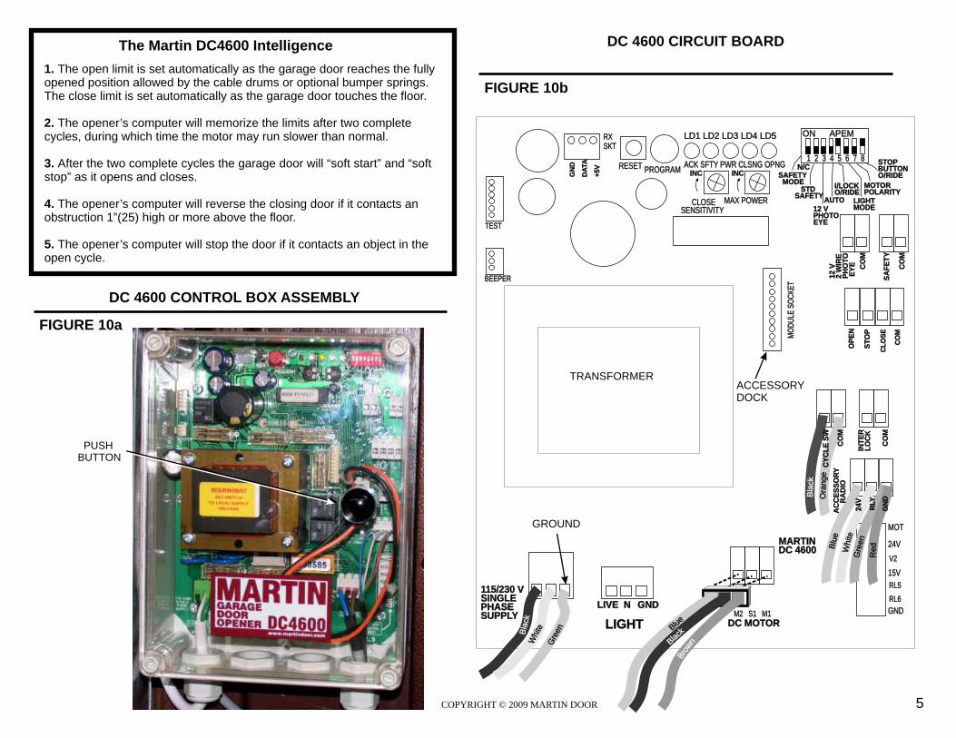
DC 4600 CONTROL BOX ASSEMBLY
FIGURE 10b
12
V
2 W
IRE
PH
OT
O E
YE CO
M
MOT
24V
GND
MARTINDC 4600
LD1 LD2 LD3 LD4 LD5
ACK SFTY PWR CLSNG OPNG
ON APEM
1 2 3 4 5 6 7 8
INC
STDSAFETY
12 VPHOTOEYE
I/LOCKO/RIDE
LIGHTMODE
PROGRAMRESET
CLOSESENSITIVITY
MAX POWER
N/C
BEEPER
TEST
RXSKT
GN
D
DA
TA
+5
V
V2
RL5
RL6
COPYRIGHT © 2009 MARTIN DOOR 5
Gre
en
LIGHTlack
Bh
Wite
The Martin DC4600 Intelligence
FIGURE 10a
OP
EN
ST
OP
CO
M
CL
OS
E
ACCESSORYDOCK
GROUND
DC 4600 CIRCUIT BOARD
PUSH BUTTON
GND LIVE N
Wh
tei
115/230 VSINGLEPHASESUPPLY
DC MOTORM2 S1 M1
INT
ER
LO
CK
CO
MS
AF
ET
Y
CO
M
15V
eO
rang
CO
M
MO
DU
LE S
OC
KE
T
24V
RLY
GN
D
Red
Gr
en
eht
Wi e
Blu
e
AUTO
MOTORPOLARITY
STOPBUTTONO/RIDESAFETY
MODE
1. The open limit is set automatically as the garage door reaches opened position allowed by the cable drums or optional bumper springs. The close limit is set automatically as the garage door touches the floor.
2. The opener’s computer will memorize the limits after two complete cycles, during which time the motor may run slower than normal.
3. After the two complete cycles the garage door will “soft start” and “soft stop” as it opens and closes.
4. The opener’s computer will reverse the closing door if it contacts an obstruction 1”(25) high or more above the floor. 5. The opener’s computer will stop the door if it contacts an object in the open cycle.
the fully
Blue
Br
now
Black
INC
Bla
ck
CY
CL
E S
W
AC
CE
SS
OR
Y
R
AD
IO
TRANSFORMER
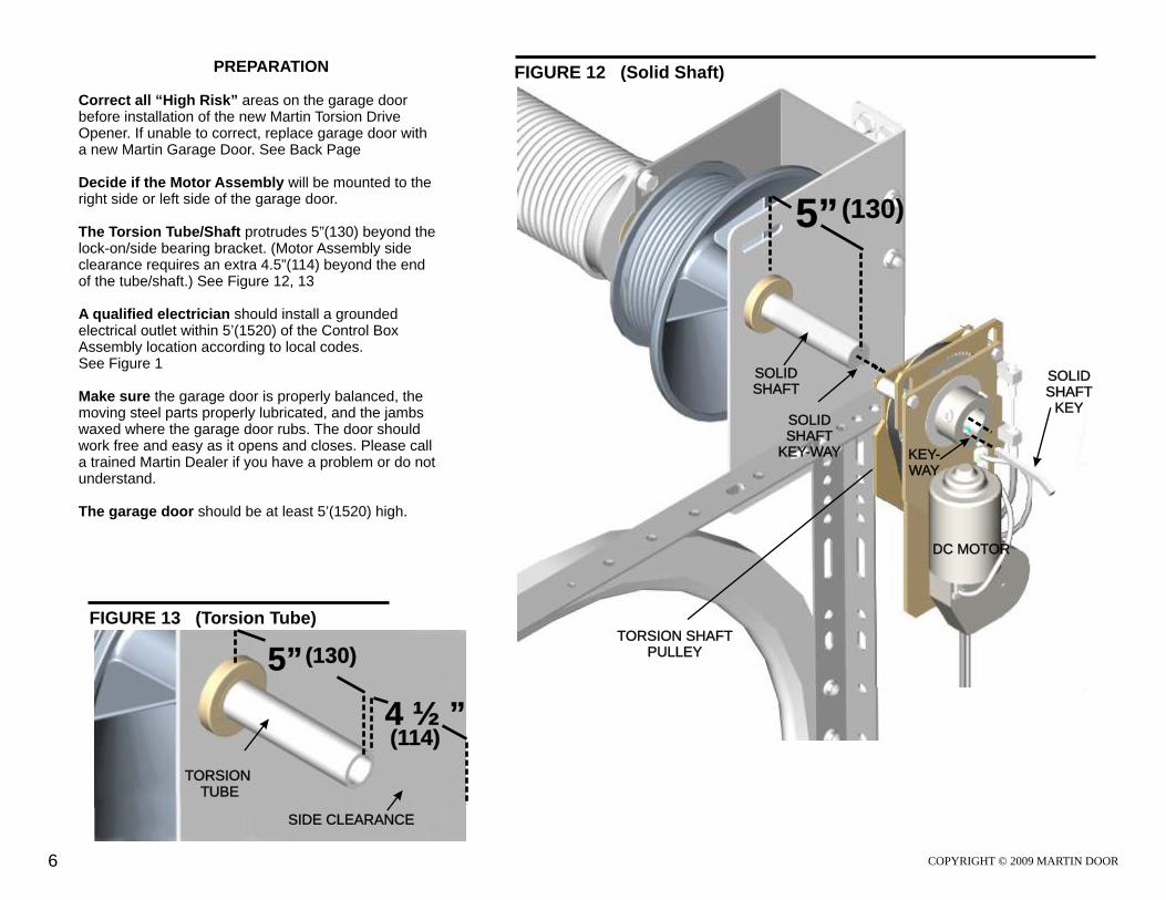
PREPARATION Correct all “High Risk” areas on the garage door before installation of the new Martin Torsion Drive Opener. If unable to correct, replace garage door with a new Martin Garage Door. See Back Page
Decide if the Motor Assembly will be mounted to the right side or left side of the garage door.
The Torsion Tube/Shaft protrudes 5”(130) beyond the lock-on/side bearing bracket. (Motor Assembly side clearance requires an extra 4.5”(114) beyond the end of the tube/shaft.) See Figure 12, 13
A qualified electrician should install a grounded electrical outlet within 5’(1520) of the Control Box Assembly location according to local codes. See Figure 1 Make sure the garage door is properly balanced, the moving steel parts properly lubricated, and the jambs waxed where the garage door rubs. The door should work free and easy as it opens and closes. Please call a trained Martin Dealer if you have a problem or do not understand.
The garage door should be at least 5’(1520) high.
FIGURE 12 (Solid Shaft)
FIGURE 13 (Torsion Tube)
5” (130)
TORSION SHAFT PULLEY
SOLID SHAFT
SOLIDSHAFT
KEY-WAY
SOLIDSHAFT
KEY
KEY-WAY
6 COPYRIGHT © 2009 MARTIN DOOR
TORSION TUBE
5” (130)
4 ½ ”(114)
SIDE CLEARANCE
DC MOTOR
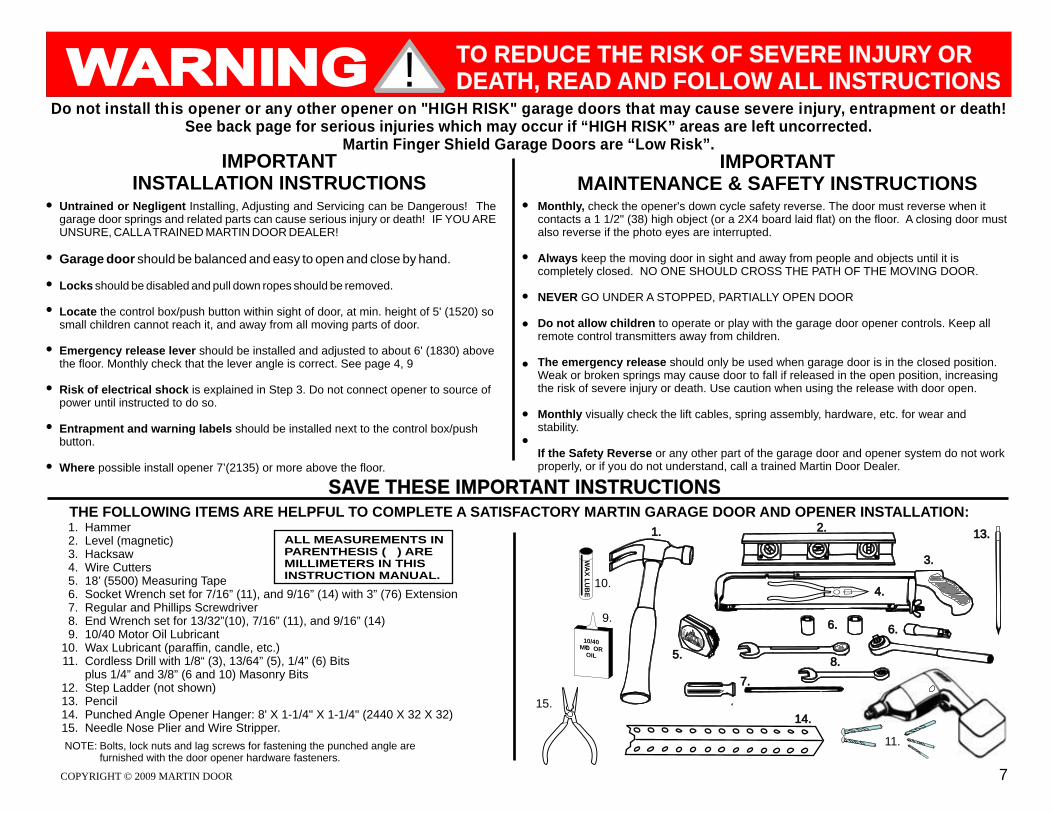
THE FOLLOWING ITEMS ARE HELPFUL TO COMPLETE A SATISFACTORY MARTIN GARAGE DOOR AND OPENER INSTALLATION:HammerLevel (magnetic)HacksawWire Cutters18’ (5500) Measuring TapeSocket Wrench set for 7/16” (11), and 9/16” (14) with 3” (76) ExtensionRegular and Phillips Screwdriver End Wrench set for 13/32”(10), 7/16” (11), and 9/16” (14)10/40 Motor Oil Lubricant Wax Lubricant (paraffin, candle, etc.)Cordless Drill with 1/8“ (3), 13/64” (5), 1/4” (6) Bits plus 1/4” and 3/8” (6 and 10) Masonry BitsStep Ladder (not shown)PencilPunched Angle Opener Hanger: 8' X 1-1/4" X 1-1/4" (2440 X 32 X 32) Needle Nose Plier and Wire Stripper.
NOTE: Bolts, lock nuts and lag screws for fastening the punched angle arefurnished with the door opener hardware fasteners.
1.2.3.4.5.6.7.8.9.
10.11.
12.13.14.15.
2.
3.
6.9.
WA
X L
UB
E
10/40OMTO R
OIL
11.
10.4.
1.
7.
MT
R
S
AOD
A
GE
ROG ITARM
N
14.
8.
6.
5.
13.ALL MEASUREMENTS IN PARENTHESIS ( ) ARE MILLIMETERS IN THIS INSTRUCTION MANUAL.
!
IMPORTANTINSTALLATION INSTRUCTIONS
Do not install th is opener or any other opener on "HIGH RISK" garage doors that may cause severe injury, entrapment or death!See back page for serious injuries which may occur if “HIGH RISK” areas are left uncorrected.
Martin Finger Shield Garage Doors are “Low Risk”.
Untrained or Negligent Installing, Adjusting and Servicing can be Dangerous! The garage door springs and related parts can cause serious injury or death! IF YOU ARE UNSURE, CALL A TRAINED MARTIN DOOR DEALER!
Garage door should be balanced and easy to open and close by hand.
Locks should be disabled and pull down ropes should be removed.
Locate the control box/push button within sight of door, at min. height of 5' (1520) so small children cannot reach it, and away from all moving parts of door.
Emergency release lever should be installed and adjusted to about 6' (1830) above the floor. Monthly check that the lever angle is correct. See page 4, 9
Risk of electrical shock is explained in Step 3. Do not connect opener to source of power until instructed to do so.
Entrapment and warning labels should be installed next to the control box/push button.
Where possible install opener 7’(2135) or more above the floor.
IMPORTANTMAINTENANCE & SAFETY INSTRUCTIONS
Monthly, check the opener's down cycle safety reverse. The door must reverse when it contacts a 1 1/2" (38) high object (or a 2X4 board laid flat) on the floor. A closing door must also reverse if the photo eyes are interrupted.
Always keep the moving door in sight and away from people and objects until it is completely closed. NO ONE SHOULD CROSS THE PATH OF THE MOVING DOOR.
NEVER GO UNDER A STOPPED, PARTIALLY OPEN DOOR
Do not allow children to operate or play with the garage door opener controls. Keep all remote control transmitters away from children.
The emergency release should only be used when garage door is in the closed position. Weak or broken springs may cause door to fall if released in the open position, increasing the risk of severe injury or death. Use caution when using the release with door open.
Monthly visually check the lift cables, spring assembly, hardware, etc. for wear and stability.
If the Safety Reverse or any other part of the garage door and opener system do not work properly, or if you do not understand, call a trained Martin Door Dealer.
TO REDUCE THE RISK OF SEVERE INJURY OR DEATH, READ AND FOLLOW ALL INSTRUCTIONS
SAVE THESE IMPORTANT INSTRUCTIONS
15.
COPYRIGHT © 2009 MARTIN DOOR 7
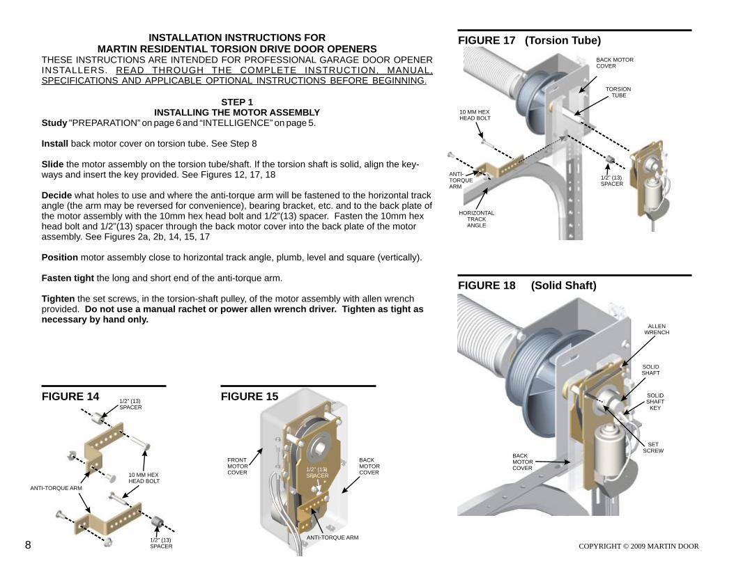
FIGURE 18 (Solid Shaft)
INSTALLATION INSTRUCTIONS FORMARTIN RESIDENTIAL TORSION DRIVE DOOR OPENERS
THESE INSTRUCTIONS ARE INTENDED FOR PROFESSIONAL GARAGE DOOR OPENER INSTALLERS. READ THROUGH THE COMPLETE INSTRUCTION, MANUAL, SPECIFICATIONS AND APPLICABLE OPTIONAL INSTRUCTIONS BEFORE BEGINNING.
STEP 1 INSTALLING THE MOTOR ASSEMBLY
Study "PREPARATION” on page 6 and “INTELLIGENCE” on page 5.
Install back motor cover on torsion tube. See Step 8
Slide the motor assembly on the torsion tube/shaft. If the torsion shaft is solid, align the key-ways and insert the key provided. See Figures 12, 17, 18
Decide what holes to use and where the anti-torque arm will be fastened to the horizontal track angle (the arm may be reversed for convenience), bearing bracket, etc. and to the back plate of the motor assembly with the 10mm hex head bolt and 1/2”(13) spacer. Fasten the 10mm hex head bolt and 1/2”(13) spacer through the back motor cover into the back plate of the motor assembly. See Figures 2a, 2b, 14, 15, 17
Position motor assembly close to horizontal track angle, plumb, level and square (vertically).
Fasten tight the long and short end of the anti-torque arm.
Tighten the set screws, in the torsion-shaft pulley, of the motor assembly with allen wrench provided. Do not use a manual rachet or power allen wrench driver. Tighten as tight as necessary by hand only.
COPYRIGHT © 2009 MARTIN DOOR
FIGURE 17 (Torsion Tube)
FIGURE 14 FIGURE 15
8
TORSION TUBE
SOLID SHAFT
SOLIDSHAFT
KEY
ANTI-TORQUE ARM
ANTI-TORQUE ARM
ANTI-TORQUE ARM
HORIZONTALTRACKANGLE
ALLENWRENCH
10 MM HEX HEAD BOLT
1/2” (13)SPACER
1/2” (13)SPACER
1/2” (13)SPACER
10 MM HEX HEAD BOLT
1/2” (13)SPACER
BACKMOTORCOVER
BACK MOTORCOVER
BACKMOTORCOVER
FRONTMOTORCOVER
SETSCREW
STEP 2 INSTALLING THE EMERGENCY RELEASE ASSEMBLY
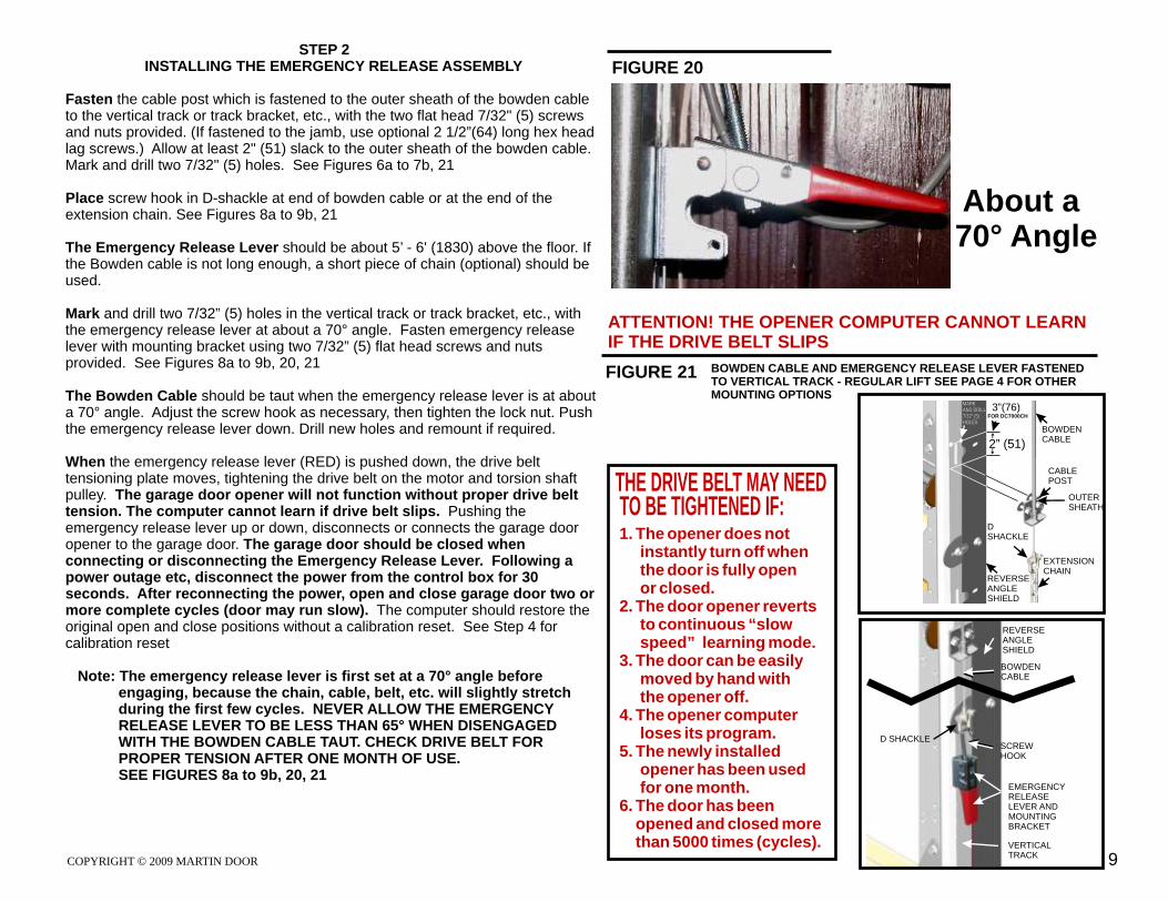
Fasten the cable post which is fastened to the outer sheath of the bowden cable to the vertical track or track bracket, etc., with the two flat head 7/32" (5) screws and nuts provided. (If fastened to the jamb, use optional 2 1/2”(64) long hex head lag screws.) Allow at least 2" (51) slack to the outer sheath of the bowden cable. Mark and drill two 7/32" (5) holes. See Figures 6a to 7b, 21
Place screw hook in D-shackle at end of bowden cable or at the end of the extension chain. See Figures 8a to 9b, 21
The Emergency Release Lever should be about 5’ - 6' (1830) above the floor. If the Bowden cable is not long enough, a short piece of chain (optional) should be used.
Mark and drill two 7/32” (5) holes in the vertical track or track bracket, etc., with the emergency release lever at about a 70° angle. Fasten emergency release lever with mounting bracket using two 7/32” (5) flat head screws and nuts provided. See Figures 8a to 9b, 20, 21 The Bowden Cable should be taut when the emergency release lever is at about a 70° angle. Adjust the screw hook as necessary, then tighten the lock nut. Push the emergency release lever down. Drill new holes and remount if required.
When the emergency release lever (RED) is pushed down, the drive belt tensioning plate moves, tightening the drive belt on the motor and torsion shaft pulley. The garage door opener will not function without proper drive belt tension. The computer cannot learn if drive belt slips. Pushing the emergency release lever up or down, disconnects or connects the garage door opener to the garage door. The garage door should be closed when connecting or disconnecting the Emergency Release Lever. Following a power outage etc, disconnect the power from the control box for 30 seconds. After reconnecting the power, open and close garage door two or more complete cycles (door may run slow). The computer should restore the original open and close positions without a calibration reset. See Step 4 for calibration reset
Note: The emergency release lever is first set at a 70° angle before engaging, because the chain, cable, belt, etc. will slightly stretch during the first few cycles. NEVER ALLOW THE EMERGENCY RELEASE LEVER TO BE LESS THAN 65° WHEN DISENGAGED WITH THE BOWDEN CABLE TAUT. CHECK DRIVE BELT FOR PROPER TENSION AFTER ONE MONTH OF USE. SEE FIGURES 8a to 9b, 20, 21
COPYRIGHT © 2009 MARTIN DOOR 9
FIGURE 21
REVERSE ANGLESHIELD
SCREW HOOK
EMERGENCYRELEASE LEVER AND MOUNTING BRACKET
VERTICALTRACK
BOWDENCABLE
D SHACKLE
BOWDEN CABLE AND EMERGENCY RELEASE LEVER FASTENED TO VERTICAL TRACK - REGULAR LIFT SEE PAGE 4 FOR OTHER MOUNTING OPTIONS
FIGURE 20
ATTENTION! THE OPENER COMPUTER CANNOT LEARNIF THE DRIVE BELT SLIPS
VERTICALTRACK
THE DRIVE BELT MAY NEED TO BE TIGHTENED IF:1. The opener does not instantly turn off when the door is fully open or closed.2. The door opener reverts to continuous “slow speed” learning mode.3. The door can be easily moved by hand with the opener off.4. The opener computer loses its program.5. The newly installed opener has been used for one month.6. The door has been opened and closed more than 5000 times (cycles).
MARK AND DRILL 7/32” (5) HOLES
MARK AND DRILL 7/32” (5) HOLES
2” (51)
BOWDENCABLE
CABLEPOST
OUTER SHEATH
D SHACKLE
REVERSE ANGLESHIELD
EXTENSIONCHAIN
3”(76) FOR DC7000CH
About a 70° Angle
STEP 3INSTALLING THE CONTROL BOX ASSEMBLY
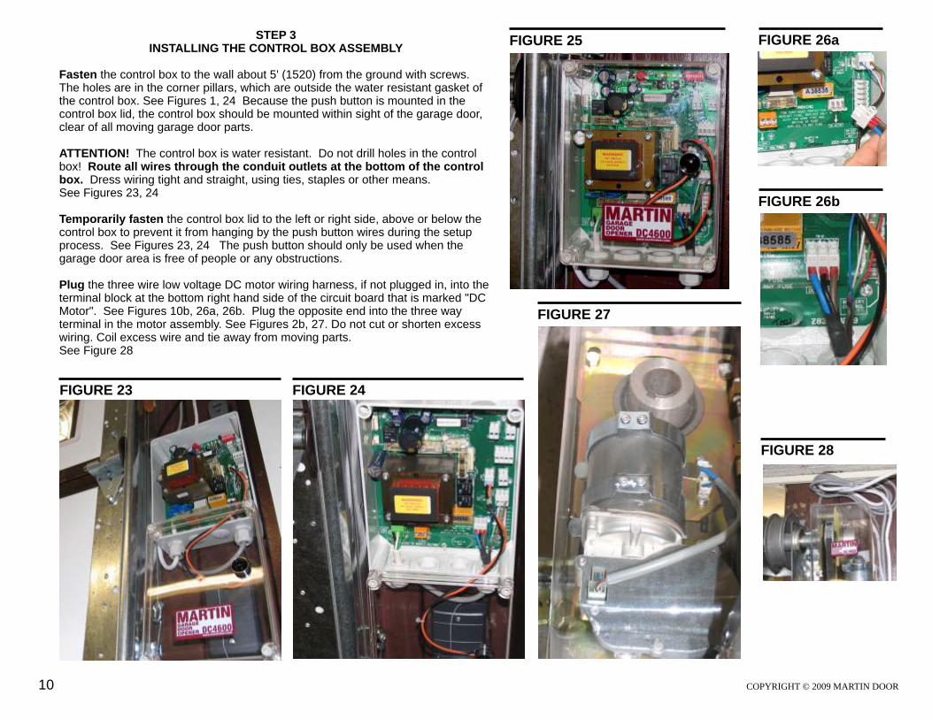
Fasten the control box to the wall about 5' (1520) from the ground with screws. The holes are in the corner pillars, which are outside the water resistant gasket of the control box. See Figures 1, 24 Because the push button is mounted in the control box lid, the control box should be mounted within sight of the garage door, clear of all moving garage door parts.
ATTENTION! The control box is water resistant. Do not drill holes in the control box! Route all wires through the conduit outlets at the bottom of the control box. Dress wiring tight and straight, using ties, staples or other means. See Figures 23, 24
Temporarily fasten the control box lid to the left or right side, above or below the control box to prevent it from hanging by the push button wires during the setup process. See Figures 23, 24 The push button should only be used when the garage door area is free of people or any obstructions.
Plug the three wire low voltage DC motor wiring harness, if not plugged in, into the terminal block at the bottom right hand side of the circuit board that is marked "DC Motor". See Figures 10b, 26a, 26b. Plug the opposite end into the three way terminal in the motor assembly. See Figures 2b, 27. Do not cut or shorten excess wiring. Coil excess wire and tie away from moving parts. See Figure 28
FIGURE 25
COPYRIGHT © 2009 MARTIN DOOR
FIGURE 28
FIGURE 23 FIGURE 24
10
FIGURE 27
FIGURE 26a
FIGURE 26b

FIGURE 30
***STEP 3 CONTINUED***
The control box assembly includes a 6’(1800) power cord with a three prong plug. The third prong is ground. To reduce the risk of electric shock do not alter or change plug or outlet in any way. Do not try to conceal or staple the power cord or try to rout it through a door way, window, wall, ceiling, floor, etc. The power cord must be routed away from moving parts. Also see “WARNING” On page 12.
Wait until Step 4 before plugging the power cord into the grounded electrical outlet.
DO NOT PINCH WIRING! The door opener will not work properly with damaged wiring.
DIP Switch Positions. See Figure 10b, 30, 31
Observe the factory set positions of each dip switch in the upper right hand corner of the circuit board.
Sw1 Safety Mode Off/Normally ClosedSw2 Standard Safety Off (On for photo-eyes, etc.)Sw3 12 Volt Photo-eye Off (On for photo-eyes, etc.)Sw4 Auto Close Off (N/A in North America)Sw5 Inter-Lock Over-Ride On (Off for inter-lock lock-out switch)Sw6 Lighting Mode Off (On eliminates light delay timer)Sw7 Motor Polarity On/Off (as required)Sw8 Stop Button Over-Ride On
See Figures 30, 31
COPYRIGHT © 2009 MARTIN DOOR 11
ACK = AcknowledgeSFTY = SafetyPWR = PowerCLSNG = ClosingOPNG = OpeningL.E.D. = Light Emitting Diode
Abbreviations RLY = RelayV = VoltN = NeutralCOM = CommonGND = GroundTX = TransmitterRX = Receiver
FIGURE 31
ON APEMs
1 2 3 4 5 6 7 8
STDSAFETY
12 VPHOTOEYE
I/LOCKO/RIDE
LIGHTMODE
N/C
AUTO
MOTORPOLARITY
STOPBUTTONOVER-RIDESAFETY
MODE
***CLEARING SERVICE DUE REMINDER INSTRUCTIONS***
At 1500 cycles, the opener may turn on a “service due reminder” (delay to close). To disable do the following:
Turn off the power (or press and hold the reset button)Press and hold the case lid buttonTurn on the power (or release the reset button)Release the case lid button after ACK flashes three timesNote the two confirmation ACK flashes

FIGURE 40STEP 4 CONNECTING OPENER TO POWER
(All basic and accessory wiring such as photo-eyes should be completed)
Plug the 6’(1830) power cord into a 10 amp minimum, grounded electrical outlet. Observe the L.E.D. Light #3 PWR illuminates at top of circuit board. If no outlet is available or if power will be wired in direct, contact a qualified electrician. Notice that the power cord wires are connected into the green “main” terminal at the bottom of the circuit board. Observe LIVE, N, and GND. See Figures 10a, 10b, 40
WARNING! To help prevent electrocution, death, fire, etc, the installation of wiring and approved grounded electrical outlet must be done in accordance with local electrical and building codes. DO NOT USE AN EXTENSION CORD. DO NOT USE A 3-PRONG TO 2-PRONG PLUG ADAPTER.Also see “The Control Box ” on page 11.
Push emergency release lever up to disconnect opener from garage door.
Manually open garage door about 3' (915).
Push emergency release lever down to reconnect opener to garage door. Press push button.
COPYRIGHT © 2009 MARTIN DOOR12
Note: The door may move slow while the computer learns the open and close limits.
Following power outage etc., disconnect power from the control box assembly with the door closed.Reconnect power. If the door performs incorrectly after three cycles, perform a calibration reset with the door closed.
Calibration Reset Press and hold reset button. Press and hold program button.
Release reset button. Wait and observe that the L.E.D. #1 ACK blinks.
Release Program Button. Observe that the L.E.D. #1 ACK blinks twice, confirming Calibration Reset. See Figure 41
The computer cannot learn if the drive belt slips. See Step 2
IF DOOR OPENS:and LED light #5 OPNG illuminatesPress push button to stop doorUnplug power cord or turn off power Push emergency release lever up Manually close garage door Push emergency release lever downPlug in power cord or turn on powerPerform Calibration Reset (see below)Press push button to open doorOpen and close door two complete cycles
IF DOOR CLOSES:Press push button to stop doorUnplug power cord or turn off powerPush Emergency Release Lever up Manually close garage door Push emergency release lever down Move dip switch #7 to the opposite position Warning! Never move dip switch #7 with power on. Plug in power cord or turn on powerPerform Calibration Reset (see below)Press push button to open doorOpen and close door two complete cycles
FIGURE 41
THE DRIVE BELT MAY NEED TO BE TIGHTENED IF:1. The opener does not instantly turn off when the door is fully open or closed.2. The door opener reverts to continuous “slow speed” learning mode.3. The door can be easily moved by hand with the opener off.4. The opener computer loses its program.5. The newly installed opener has been used for one month.6. The door has been opened and closed more than 5000 times (cycles).

TA1
LED
ANTENNA
YELLOW, RED, GREEN, BLACK WIRES
NC1
NO1
COM
1
IN1
IN2
STEP 5 RADIO CONTROL AND EXTRA PUSH BUTTON
Radio Receiver (Install before Step 4)Remove the cover. Mount the receiver on the wall, next to the control box assembly. See Figure 33
Route the receiver wires up through the conduit outlet in the control box and plug the three labeled wires to the terminals marked 24V, RLY, and GND. The terminal is marked ACCESSORY RADIO. See Figure 32
Connect the blue wire to 24V, white wire to RLY, green and red wire to GND. See Figure 32
To Program first transmitter press and hold button TA1 on receiver circuit board. See Figure 33
After three or four seconds the LED will blink for about ten seconds.
During the ten seconds press and hold transmitter button until the LED illuminates. Release transmitter button and observe that the LED turns off. Test transmitter. See Figure 33
To delete the transmitter memory in the receiver, press and hold button TA1 ten seconds. The LED will blink a few times and then illuminate. Release the button.
AntennaThe 315 MHZ receiver antenna wire on the radio receiver is about 13”(340) long and can have multiple arrangements for the best distance. In a normal installation the distance from the transmitter to the antenna wire should be 50’ to 150’(15240 to 45720). Do not lengthen or shorten the antenna wire.
NOTE: The Distance from the transmitter to the antenna may be reduced by electrical interference or spherical disturbances in the area, various lights or transformers in and out of the garage, automatic sprinkler system timers, various audible or inaudible sounds, noise, radio signals in the area, concrete, steel or lead in and around the garage, antenna wire touching metal, etc.
External Push ButtonFasten additional white w/ black stripe and white wires to Case Button terminal, in parallel with existing box cover lid push button wires. Fasten other end of wires to the external push button. See Figure 32
COPYRIGHT © 2009 MARTIN DOOR
FIGURE 33
FIGURE 32
13
3 2
4V
2 R
LY
1 G
ND
AC
CE
SS
OR
YR
AD
IO
CY
CL
E S
W
C
OM
CA
SE
BU
TT
ON
PUSHBUTTON
TO CONTROL BOXLID PUSH BUTTON
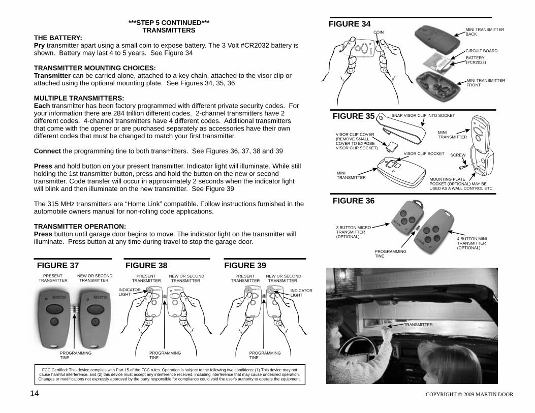
FIGURE 34***STEP 5 CONTINUED***TRANSMITTERS
THE BATTERY:Pry transmitter apart using a small coin to expose battery. The 3 Volt #CR2032 battery is shown. Battery may last 4 to 5 years. See Figure 34
TRANSMITTER MOUNTING CHOICES:Transmitter can be carried alone, attached to a key chain, attached to the visor clip or attached using the optional mounting plate. See Figures 34, 35, 36 MULTIPLE TRANSMITTERS:Each transmitter has been factory programmed with different private security codes. For your information there are 284 trillion different codes. 2-channel transmitters have 2 different codes. 4-channel transmitters have 4 different codes. Additional transmitters that come with the opener or are purchased separately as accessories have their own different codes that must be changed to match your first transmitter.
Connect the programming tine to both transmitters. See Figures 36, 37, 38 and 39 Press and hold button on your present transmitter. Indicator light will illuminate. While still holding the 1st transmitter button, press and hold the button on the new or second transmitter. Code transfer will occur in approximately 2 seconds when the indicator light will blink and then illuminate on the new transmitter. See Figure 39
The 315 MHz transmitters are “Home Link” compatible. Follow instructions furnished in the automobile owners manual for non-rolling code applications.
TRANSMITTER OPERATION:Press button until garage door begins to move. The indicator light on the transmitter will illuminate. Press button at any time during travel to stop the garage door.
FIGURE 35
FIGURE 36
FIGURE 37
SNAP VISOR CLIP INTO SOCKET
FIGURE 38 FIGURE 39
FCC Certified: This device complies with Part 15 of the FCC rules. Operation is subject to the following two conditions: (1) This device may not cause harmful interference, and (2) this device must accept any interference received, including interference that may cause undesired operation. Changes or modifications not expressly approved by the party responsible for compliance could void the user's authority to operate the equipment.
MINITRANSMITTER
PRESENTTRANSMITTER
NEW OR SECOND TRANSMITTER
PRESENTTRANSMITTER
NEW OR SECOND TRANSMITTER
INDICATORLIGHT
MARTIN MARTIN MARTINMARTIN
PRESENTTRANSMITTER
NEW OR SECOND TRANSMITTER
INDICATORLIGHT
MA
RT
IN
COIN
VISOR CLIP COVER(REMOVE SMALL COVER TO EXPOSE VISOR CLIP SOCKET)
VISOR CLIP SOCKET
PROGRAMMINGTINE
MINI TRANSMITTERBACK
BATTERY(#CR2032)
MINI TRANSMITTERFRONT
CIRCUIT BOARD
3 BUTTON MICRO TRANSMITTER(OPTIONAL)
4 BUTTON MINI TRANSMITTER(OPTIONAL)
MRT N
AI
SCREW
MOUNTING PLATE POCKET (OPTIONAL) MAY BE USED AS A WALL CONTROL ETC.
MINITRANSMITTER
PROGRAMMINGTINE
PROGRAMMINGTINE
PROGRAMMINGTINE
MARTIN
TRANSMITTER
COPYRIGHT © 2009 MARTIN DOOR14

FIGURE 44
STEP 6 PROGRAMMING THE GARAGE DOOR OPENER SYSTEM
Press the push button to open door. Observe that LED #5 OPNG illuminates as the garage door opens. The garage door will stop when it reaches the full open position allowed by the cable drums or optional bumper springs. Press the push button to close the door. Observe that LED #4 CLSNG illuminates as the garage door closes. The garage door will stop when it reaches the floor. If OPNG or CLSNG light does not go out when door stops, the belt tension may need to be adjusted (Max Power and Close Sensitivity may also need adjusting). See Figure 43
Open and close garage door two more complete cycles. Observe the movement of the garage door as the computer memorizes the open and close position. You may notice that LED #1 ACK illuminates from time to time. The garage door opener system now provides “soft start” and “soft stop” as the door opens and closes. See Figure 43
Do Not touch the following settings unless you are sure.Force Setting: MAX POWER is factory set at one o’clock. Force can be slightly increased by turning screw clockwise 10 degrees at a time. See Figure 10b, 43Sensitivity Setting: CLOSE SENSITIVITY is factory set at one o’clock. Sensitivity can be increased by turning screw clockwise 10 degrees at a time. See Figure 10b, 43
Place a 1 1/2”(38) high object (or a 2X4 laid flat) on the floor, under the door. When the closing door contacts the object, it should stop, reverse, and automatically return to the open position. See Figure 44If the door does not reverse, the drive belt may be slipping. After correcting drive belt tension and the door still does not reverse, call a trained Martin Door dealer. See Step 2
STEP 7 INSERT INSTRUCTION MANUAL INTO PACKET
Fold and Insert instruction manual into the packet located on the #3 door section of the Martin garage door or mount to the wall.An Important safety/instruction label is included with opener package. This label and the instruction manual must be fastened inside your garage where they can be easily seen. Fasten them next to the wall control box. Peel off the protective backing, and press onto smooth, clean surface. Tacks or additional adhesive may be necessary. DO NOT REMOVE OR PAINT OVER ANY LABELS. See Figures 45, 46
COPYRIGHT © 2009 MARTIN DOOR 15
FIGURE 43
FIGURE 46
!
8/2001 AD-01IM-03
INSTRUCTION MANUAL
For all Residential Garage Doors up to 12’ (3700) High.
GGARA E DOOR
NOPE ER SIN TRUCTION
L MANUA ANDNWARI NG
L EAB L
T F L A PMAR IN INGER SHIE D G RAGE DOOR AND O ENER SYSTEM S A IN TRUCTION M NUALS AND WARNING LABEL T E (FAC ORY PACKAG D AND MOUNTED)
CONTROLBOX
ASSEMBLYAND PUSHBUTTON
MOTOR ASSEMBLY
TMDOOR OPENERSARTINM
FIGURE 45 A KET P C
(F T M N E )AC ORY OU T D
L DFO D AN IN T SER IN UC N STR TIOMANU ALINTO KET PAC
1 1/2”(38) HIGH OBJECTFOR DOOR REVERSAL TEST

OO
BACK MT
R
E
COVR
FRONT COVER MOTORBARREL CLIPS
MOTORBARREL
PEGS
HOLES
CLIPS
IMPORTANT MAINTENANCE & SAFETY INSTRUCTIONS Monthly, check the opener's down cycle safety reverse. The door must reverse when it contacts a 1 1/2" (38) high object (or a 2X4 board laid flat) on the floor. A closing door must also reverse if the optional photo eyes are interrupted.
Always keep the moving door in sight and away from people and objects until it is completely closed. NO ONE SHOULD CROSS THE PATH OF THE MOVING DOOR.
NEVER go under a stopped, partially open door.
Do not allow children to operate or play with the garage door controls. Keep the remote control away from children.
SAVE THESE IMPORTANT INSTRUCTIONS
If the Safety Reverse or any other part of the garage door and opener system do not work properly, or if you do not understand, call a trained Martin Door Dealer.
The emergency release should only be used when garage door is in the closed position.Weak or broken springs may cause door to fall, if released in the open position, increasing the risk of severe injury or death. Use caution when using the release with door open.
Monthly visually check lift cables, spring assembly, hardware, etc. for wear and stability.
KEEP GARAGE DOOR PROPERLY BALANCED. See garage door owner’s manual. An improperly balanced door increases the risk of severe injury or death. Call a trained Martin Door Dealer to repair lift cables, spring assemblies and other hardware.
! TO REDUCE THE RISK OF SEVERE INJURY OR DEATH, READ AND FOLLOW ALL INSTRUCTIONS
STEP 8 INSTALLING THE FRONT MOTOR COVER
The front cover has two motor barrel clips, which fasten over the motor barrel. Position the front cover with the clips touching the motor barrel, then with a hand over the clip area, firmly push the front cover until the clips fasten to the motor barrel. Fit the two pegs located in the top edge of the back cover into the two holes located in the top edge of the front cover. Fasten front and back cover together with the small screws into the small clips. See Figures 2a, 2b, 47
FIGURE 47
INTERLOCK CIRCUIT WIRING
A pair of “Interlock” terminals is provided for a pass door switch or a key switch (lock-out switch) to be interlocked to the opener, to prevent the garage door from opening if the “Interlock” terminals are open circuit. See Figure 10b, 48a
Interlock O/RIDE, DIP switch No. 5 is normally set to ON. If you want to add an interlock device, move switch No. 5 to OFF. See Figure 10b, 48b
A slide lock switch may be installed and connected into the interlock terminals. However this may not be necessary because the opener will detect the obstruction and stop the garage door if the slide lock is left in the lock position.
FIGURE 48a SW5 TO “OFF” POSITION
INT
ER
LO
CK
CO
M
FIGURE 48b
ON APEMs
1 2 3 4 5 6 7 8
I/LOCKO/RIDE
COPYRIGHT © 2009 MARTIN DOOR16
17
FIGURE 49SAFETY CIRCUIT WIRING (Photo-eyes required for U.L. 325 compliance)
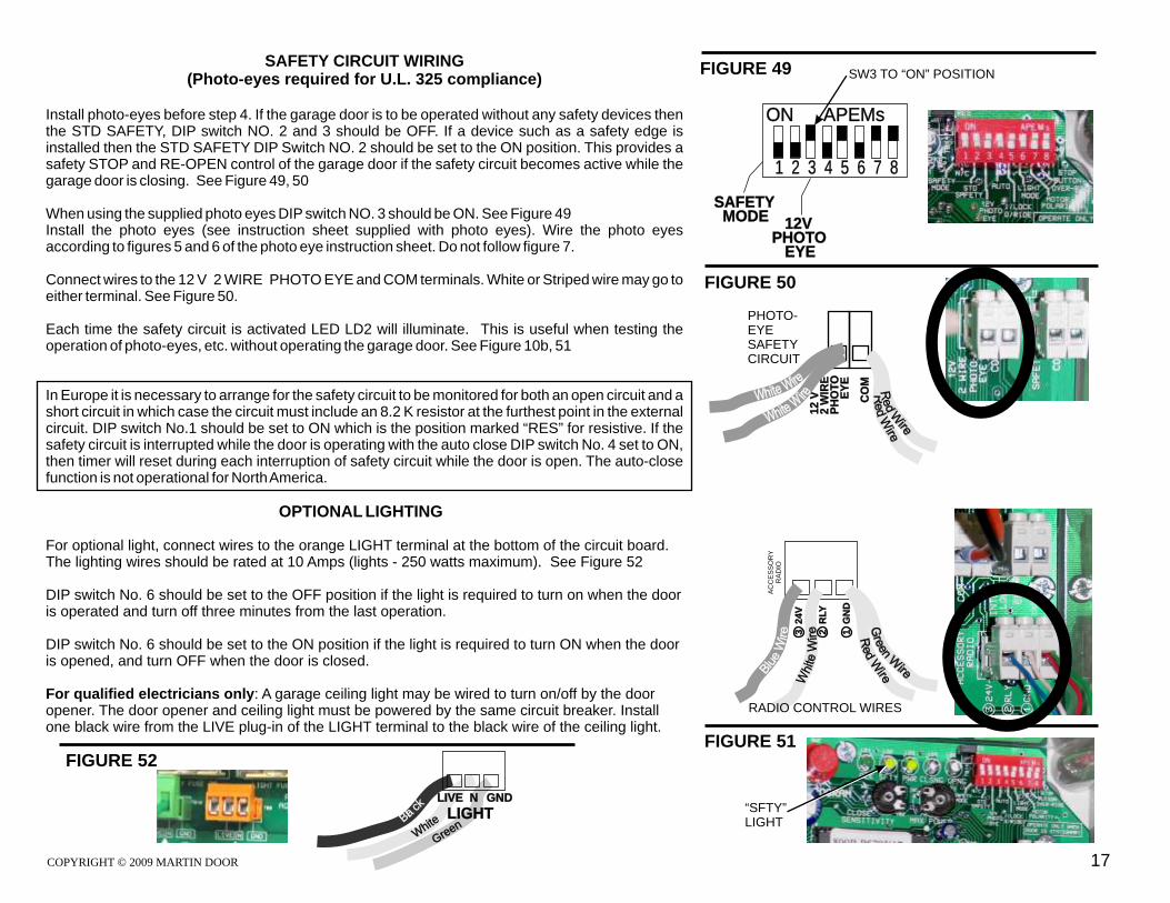
Install photo-eyes before step 4. If the garage door is to be operated without any safety devices then the STD SAFETY, DIP switch NO. 2 and 3 should be OFF. If a device such as a safety edge is installed then the STD SAFETY DIP Switch NO. 2 should be set to the ON position. This provides a safety STOP and RE-OPEN control of the garage door if the safety circuit becomes active while the garage door is closing. See Figure 49, 50
When using the supplied photo eyes DIP switch NO. 3 should be ON. See Figure 49Install the photo eyes (see instruction sheet supplied with photo eyes). Wire the photo eyes according to figures 5 and 6 of the photo eye instruction sheet. Do not follow figure 7.
Connect wires to the 12 V 2 WIRE PHOTO EYE and COM terminals. White or Striped wire may go to either terminal. See Figure 50.
Each time the safety circuit is activated LED LD2 will illuminate. This is useful when testing the operation of photo-eyes, etc. without operating the garage door. See Figure 10b, 51
In Europe it is necessary to arrange for the safety circuit to be monitored for both an open circuit and a short circuit in which case the circuit must include an 8.2 K resistor at the furthest point in the external circuit. DIP switch No.1 should be set to ON which is the position marked “RES” for resistive. If the safety circuit is interrupted while the door is operating with the auto close DIP switch No. 4 set to ON, then timer will reset during each interruption of safety circuit while the door is open. The auto-close function is not operational for North America.
OPTIONAL LIGHTING
For optional light, connect wires to the orange LIGHT terminal at the bottom of the circuit board. The lighting wires should be rated at 10 Amps (lights - 250 watts maximum). See Figure 52
DIP switch No. 6 should be set to the OFF position if the light is required to turn on when the door is operated and turn off three minutes from the last operation.
DIP switch No. 6 should be set to the ON position if the light is required to turn ON when the door is opened, and turn OFF when the door is closed.
For qualified electricians only: A garage ceiling light may be wired to turn on/off by the door opener. The door opener and ceiling light must be powered by the same circuit breaker. Install one black wire from the LIVE plug-in of the LIGHT terminal to the black wire of the ceiling light.
FIGURE 50
SW3 TO “ON” POSITION
ON APEMs
1 2 3 4 5 6 7 8
12VPHOTO EYE
SAFETY MODE
12
V2
WIR
EP
HO
TO
E
YE
CO
M
AC
CE
SS
OR
YR
AD
IO
FIGURE 51
3 2
4V
2 R
LY
1 G
ND
PHOTO-EYESAFETY CIRCUIT
RADIO CONTROL WIRES
“SFTY” LIGHT
eGr en
Bak
lc
eW
hit LIGHT
GND LIVE N
FIGURE 52
COPYRIGHT © 2009 MARTIN DOOR
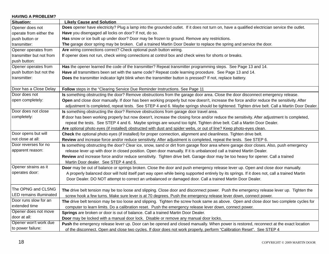
HAVING A PROBLEM?
Situation: Likely Cause and Solution
Opener does not
operate from either the
push button or
transmitter:
Opener operates from
transmitter but not from
push button:
Opener operates from
push button but not the
transmitter:
Door has a Close Delay
Door does not
open completely:
Door does not close
completely:
Door opens but will
not close at all:
Door reverses for no
apparent reason:
Opener strains as it
operates door:
The OPNG and CLSNG
LED remains illuminated
Door runs slow for an
extended time
Opener does not move
door at all:
Opener won't work due
to power failure:
Does opener have electricity? Plug a lamp into the grounded outlet. If it does not turn on, have a qualified electrician service the outlet.
Have you disengaged all locks on door? If not, do so.
Has snow or ice built up under door? Door may be frozen to ground. Remove any restrictions.
The garage door spring may be broken. Call a trained Martin Door Dealer to replace the spring and service the door.
Are wiring connections correct? Check optional push button wiring.
If opener does not run, check wiring connections at control box and check wires for shorts or breaks.
Has the opener learned the code of the transmitter? Repeat transmitter programming steps. See Page 13 and 14.
Have all transmitters been set with the same code? Repeat code learning procedure. See Page 13 and 14.
Does the transmitter indicator light blink when the transmitter button is pressed? If not, replace battery.
Follow steps in the “Clearing Service Due Reminder Instructions. See Page 11
Is something obstructing the door? Remove obstructions from the garage door area. Close the door disconnect emergency release.
Open and close door manually. If door has been working properly but now doesn't, increase the force and/or reduce the sensitivity. After
adjustment Is completed, repeat tests. See STEP 4 and 6. Maybe springs should be tightened. Tighten drive belt. Call a Martin Door Dealer.
Is something obstructing the door? Remove obstructions from garage door travel area.
If door has been working properly but now doesn't, increase the closing force and/or reduce the sensitivity. After adjustment Is completed,
repeat the tests. See STEP 4 and 6. Maybe springs are wound too tight. Tighten drive belt. Call a Martin Door Dealer.
Are optional photo eyes (if installed) obstructed with dust and spider webs, or out of line? Keep photo-eyes clean.
Check the optional photo eyes (if installed) for proper connection, alignment and cleanliness. Tighten drive belt.
Review and increase force and/or reduce sensitivity. After adjustment is completed, repeat the tests.
Is something obstructing the door? Clear ice, snow, sand or dirt from garage floor area where garage door closes. Also, push emergency
release lever up with door in closed position. Open door manually. If it is unbalanced call a trained Martin Dealer.
Review and increase force and/or reduce sensitivity. Tighten drive belt. Garage door may be too heavy for opener. Call a trained
Martin Door dealer.
Door may be out of balance or springs broken. Close the door and push emergency release lever up. Open and close door manually.
A properly balanced door will hold itself part way open while being supported entirely by its springs. If it does not, call a trained Martin
Door Dealer. DO NOT attempt to correct an unbalanced or damaged door. Call a trained Martin Door Dealer.
The drive belt tension may be too loose and slipping. Close door and disconnect power. Push the emergency release lever up. Tighten the
screw hook a few turns. Make sure lever is at 70 degrees. Push the emergency release lever down, connect power.
Springs are broken or door is out of balance. Call a trained Martin Door Dealer.
Door may be locked with a manual door lock. Disable or remove any manual door locks.
Push the emergency release lever up. Door can be opened and closed manually. When power is restored, reconnect at the exact location
of the disconnect. Open and close two cycles. If door does not work properly, perform “Calibration Reset”. See STEP 4
See STEP 6.
See STEP 4 and 6.
The drive belt tension may be too loose and slipping. Tighten the screw hook same as above. Open and close door two complete cycles for
computer to learn limits. Do a calibration reset. Push the emergency release lever down, connect power.
COPYRIGHT © 2009 MARTIN DOOR18
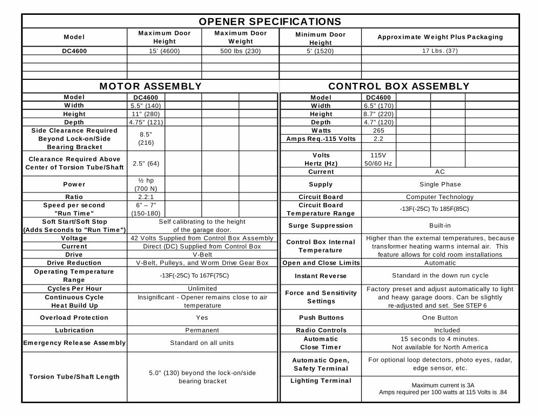
DC4600 Model DC4600
5.5" (140) W idth 6.5” (170)
11" (280) Height 8.7" (220)
4.75" (121) Depth 4.7” (120)
W atts 265
Am ps Req.-115 Volts 2.2
Volts
Hertz (Hz)
115V
50/60 Hz
Current
½ hp
(700 N)Supply
2.2:1 Circuit Board
6” – 7”
(150-180)
Circuit Board
Tem pera ture Range
Surge Suppression
Open and Close Lim its
Insta nt Reverse
Push Buttons
Radio Controls
Autom atic
Close Tim er
Autom atic Open,
Safe ty Term ina l
Lighting Term ina l
Lubrica tion Permanent
Unlimited
Continuous Cycle
Heat Build Up
Insignificant - Opener remains c lose to air
temperature
Cycles Per Hour
Current
Yes
Drive Reduction
Clearance Required Above
Cente r of Torsion Tube /Shaft
Volta ge
Side Clearance Required
Beyond Lock-on/Side
Bearing Bracket
8.5"
(216)
Ratio
CONTROL BOX ASSEMBLY
Em ergency Re lease Assem bly Standard on all units
MOTOR ASSEMBLY
Operating Tem pera ture
Range
Overload Prote ction
2.5" (64)
Torsion Tube /Shaft Length
AC
5’ (1520) 17 Lbs . (37)500 lbs (230)
OPENER SPECIFICATIONS Minim um Door
He ightModel
DC4600
Maxim um Door
W e ight
Max im um Door
He ight
15’ (4600)
Height
W idth
Depth
Pow er
5.0" (130) beyond the lock-on/side
bearing bracket
Drive V-Belt
Approx im ate W eight Plus Packaging
Automatic
Standard in the down run cycle
Model
For optional loop detectors , photo eyes, radar,
edge sensor, etc.
For optional on/off lighting
Amps required per 100 watts at 115 Volts is .84
15 seconds to 4 minutes.
Not available for North America
Single Phase
Speed per second
"Run Tim e"
Soft Sta rt/Soft Stop
(Adds Seconds to "Run Tim e")
Self calibrating to the height
of the garage door.
Computer Technology
V-Belt, Pulleys, and W orm Drive Gear Box
-30 F (-34 C) to 212 F (100 C)
-13 F (-22 C) to 212 F (100 C)
Built-in
Control Box Inte rna l
Tem pera ture
Higher than the external temperatures, because
transformer heating warms internal air. This
feature allows for cold room installations
Direct (DC) Supplied from Control Box
42 Volts Supplied from Control Box Assembly
Force and Sensitivity
Settings
Factory preset and adjust automatically to light
and heavy garage doors. Can be slightly
re-adjusted and set (See Step 5).
One Button
Included
-13F(-25C) To 185F(85C)
. See STEP 6
-13F(-25C) To 167F(75C)
Maximum current is 3AAmps required per 100 watts at 115 Volts is .84

COPYRIGHT © 2009 MARTIN DOOR
Wide open section joint
l s n!
C o i g Door
HIGHRISK
LargeHoles
inTrack
M v no i gDoor!
Wide OpenSection Joint
Clos n or!i g Do
Outside LiftCables
HIGHRISK
HIGHRISK
TrackBrackets
Closing Door!
HIGHRISK
HIGHRISK
SharpTrack
loi
Dr
Cs ng
oo !
ExposedR eroll
HIGHRISK
TrackBracket
Holes
Inside
o D
or
Door
HIGHRISK
Wide OpenSection Joint
Wide Open
Outside
SIDE VIEW
LOOSE NAILS
LOOSE LAG SCREWS
TORSIONSPRING
CRACK
SPLIT
WOOD
Center Mount Torsion SpringsTORSIONSPRING
FRONT VIEW HIGH RISK
Holes
COMMON HIGH RISK GARAGE DOOR AREAS
Exposed wide-open section joints, inside and outside . . . . . . . . . . . . . . . . . . . . . .
Exposed holes in tracks larger than 1/4" (7) . . . . . . . . . . . . . . . . . . . . . . . . . . . . . . .
Exposed track brackets fastening vertical tracks to jambs . . . . . . . . . . . . . . . . . . .
Exposed outside lift cables . . . . . . . . . . . . . . . . . . . . . . . . . . . . . . . . . . . . . . . . . . . .
Exposed rollers moving in vertical tracks with sharp leading edges. . . . . . . . . . . . .
Exposed center mount torsion springs bracket or side mount stretch springs . .
COMMON REPORTED SERIOUS INJURIES
Hands & fingers entrapped, severed or crushed. 1/3 are children.
Fingers entrapped or severed. Most are children.
Hands & arms entrapped, broken or severed. Most are children.
Entrapment or strangulation. Most are children.
Fingers entrapped, cut or severed.
Severing of body parts and death.
!
IF UNSURE, CALL A TRAINED MARTIN DOOR DEALER
Correct all “HIGH RISK” areas before installing opener.
If unable to correct “HIGH RISK” areas, replace with a new Martin Door.