
M. Gilchriese Integrated Stave Mechanics/Cooling June 5, 2008 CERN.
Upload
wendy-stanleyCategory
view
216download
1
M. Gilchriese
ATLAS UpgradeMechanics/Cooling and System Design
by LBL
January 2008

M. Gilchriese2
Motivation
• Pixels– Material reduction, particularly for B-layer => improvement in light
quark rejection(for given b-tagging efficiency), although how much is physics dependent.
• Strips– Increased integration ie. staves(or equivalent in forward direction)
– Material reduction would be nice, but not the principal motivation
• Pixels and Strips– Improved system design – more system engineering up front
– What does that mean?• Integrated design of electrical and optical services(power, signals) and
cooling(plumbing) to lead to lower material and better reliability
• Weakest area of current ATLAS ID(particularly the plumbing…)
• Requires substantial(and continuous) engineering and technical support, well coordinated

M. Gilchriese3
Pixels
• Two areas of activity so far– Layouts for B-layer replacement alternatives that can be generalized to SLHC
in the barrel region – see Maurice’s talk– Development of concepts using low-density, thermally conducting carbon foam.
• Why foam?– Perhaps applicable to both “monolithic” structures and staves. Note that “stave”
here also means equivalent for disks(pie sectors similar to ones we made for current pixel system).
– My original idea was to see if carbon nanotubes(CBNT)(that have very high thermal conductivity along their length) could be joined into foam….but quickly found out this seems to be difficult…but then
– Fortuitous coincidence of ongoing development of low density, modest thermally conductive foam for different applications (radiators for space craft and for military aircraft) in company with whom I worked on current pixels…interested in development of their concept and also of CBNT foam
– Not really explored much previously. Why? Carbon foams with good thermal conductivity have existed for years but dense(typically 0.5 g/cc or so) and expensive

M. Gilchriese4
Very Early Concepts• Foam• Cooling tube(glued to foam)• Surface for mounting modules• Structural support from carbon
fiber “skins” glued to foam
88mm
37.5mm
24.4mm

M. Gilchriese5
Low Density, Thermally Conducting Foam
• The development underway starts with Reticulated Vitreous Carbon (RVC) foam that has a density of about 0.06 g/cc and a thermal conductivity of about 0.07 W/m-K
• Through a proprietary chemical vapor deposition (CVD) process, oriented, highly conducting carbon is deposited on the RVC ligaments by Allcomp, Inc.
• This greatly enhances the thermal conductivity(goal is about factor of 600) and improves the strength
• Very roughly we think the thermal conductivity K is related to the density by
K ~ (1000-1200) x ( - 0.06)/(2.2 x “wiggle factor”)
or about 30+/-10, maybe.
• Insufficient data so far to verify this simplistic formula
• Note if CBNT could be made into foam……
K ~ 1400 x /(2.2 x “wiggle factor”)

M. Gilchriese6
Pixel Stave Prototype Development
• Thermally conducting foam obtained from Allcomp, Inc– 0.18 g/cc as delivered
– Thermal conductivity not measured (yet)
• Small prototype (20 cm long and about 2.4 cm wide) made – see photos on next pages– Small aluminum tube(2.9mm OD and 2.3mm ID) used to simulate
about what might be used for CO2 at SLHC
– Foam machined (easy) to shape and with groove for tube
– CGL7018 used to couple tube to foam
– Hysol 9396 loaded with Boron Nitride (30% by weight) used to couple facings to foam
• One facing is YSH70 cloth, 140 microns thick
• Second facing is K13D2U 4-ly laminate 300 microns thick (90-0-0-90 orientation)
M. Gilchriese7
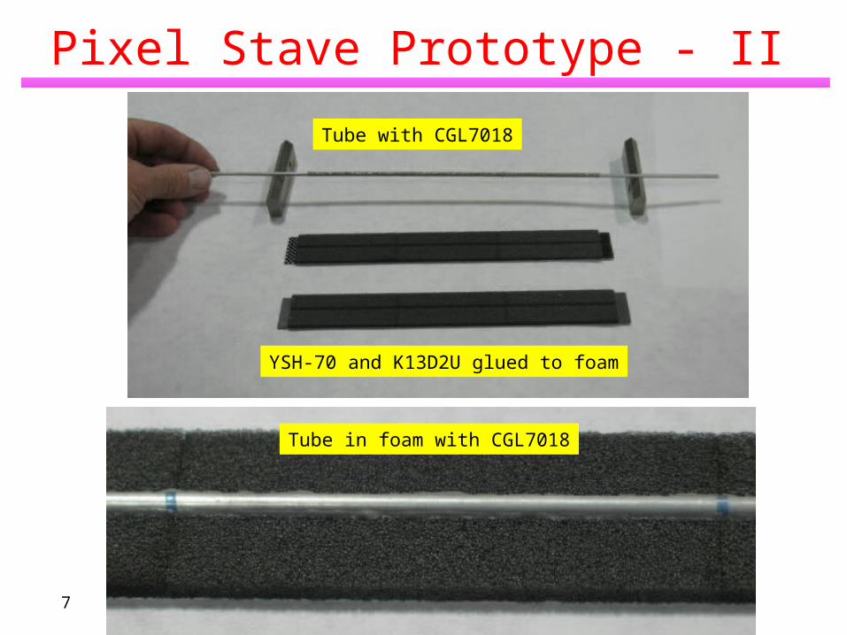
Pixel Stave Prototype - II
Tube with CGL7018
YSH-70 and K13D2U glued to foam
Tube in foam with CGL7018

M. Gilchriese8
Pixel Stave Prototype - III
• Final assembly(foam+fiber halves glued together around tube)
• Platinum-on-silicon heater in middle to simulate pixel module and copper-kapton heaters on either side to minimize end effects.
6.9 mm
24 mm
Foam
260mg/cm2
(exc. Pipe)=> 130mg/cm2 for
X0 of C is 42.7 g/cm2

M. Gilchriese9
Thermal Performance
• IR camera used
• Water coolant at 1.0 l/min at 20C.
• Vary power level in silicon heater
• And separately in copper-kapton heaters to about match Power/Area
Label Emis BG Ave SD Max Min UnitA1 0.95 19.0 27.41 0.65 28.4 25.9 CA2 0.95 19.0 27.36 0.80 28.4 23.8 C
T in boxes

M. Gilchriese10
Results
0
2
4
6
8
10
12
14
16
0.00 0.10 0.20 0.30 0.40 0.50 0.60 0.70
P/A(W/cm^2)
De
lta
T a
ve
rag
e
YSH-70 only
K13D2U only
YSH-70 sideHeat both
K13D2U sideHeat both
Note if CO2 used as coolantthen reference temperature could be about -30C. Thusdelta T of 10 => T of -20C.
FE
-I4
goal
FE
-I3
norm
al
Max
. sp
ecIncludes sensors & power conv. But not cables.

M. Gilchriese11
Nominal Design – Short Strips
Bus cable
Hybrids Coolant tube structure
Carbon honeycomb or foam
Carbon fiberfacing
Readout IC’s
10cm detectors, each with 4 rows of chips on hybrids
Hybrids glued to detectors and this assembly glued to mechanical/cooling support
~ 1 meter

M. Gilchriese12
What Has Been Done• Prototypes fabricated and studied
– 1m long for mounting silicon modules(see talk by Haber)– Three thermal prototypes, each about 1/3m long, with heaters, silicon, cables, dummy
hybrids to simulate nominal design• Three different tube types(to simulate compatibility with C3F8, C2F6/C3F8 mixtures and CO2)• Varied facing thickness and adhesives• Thermal measurements(IR imaging) before and after thermal cycling from 20C <-> -35C fifty times
completed• Measured weights as input to material calculations
– Preliminary demonstration of removal/replacement of silicon on stave completed.
• Design studies and FEA– Primarily of nominal design(hybrids glued top of silicon, short strips)
• Thermal performance and thermal runaway• Gravitational deflections and support concepts• Thermal distortion (as detector is cooled down)• Long strips ie. outer barrels.
– But also some work on • Bridged hybrid
• Other – hermeticity, endcaps, production, R&D plan, risks………..• Summary only here – see Backup slides and references therein
From presentation for ValenciaUpgrade R&D meeting in Dec.

M. Gilchriese13
Prototype Construction
1m prototype
2.8mm tube/foam
4.9 mm tube/foam
Flattened tube
Note prototype width is about 7cm – set in 2006
POCO foam: about 0.5 g/cc thermally conducting carbon foam
Facings are K13D2U fiber laminates
Carbon honeycomb
All tubes aluminum

M. Gilchriese14
Thermal Prototypes
Water at about 20C
IR images
Before andafter thermal cycling between20C and -35C50 times
Bus cableAluminahybrids
Heaters 0.3mm silicon
Label Emis BG Ave SD Max Min Unit A1 0.95 19.0 24.76 0.67 26.4 23.6 C A2 0.95 19.0 24.86 0.71 26.4 23.5 C A3 0.95 19.0 24.15 0.69 26.3 22.9 C A4 0.95 19.0 24.81 0.75 26.4 23.5 C A5 0.95 19.0 24.49 0.67 26.1 23.4 C
Label Emis BG Ave SD Max Min Unit A1 0.95 19.0 20.63 0.12 20.9 20.4 C A2 0.95 19.0 20.57 0.12 20.9 20.4 C
3.3 W/hybrid(0.55 W/chip)
No Power

M. Gilchriese15
Major Prototype Lessons• Thermal performance - T between coolant and dummy detector
– Same after thermal cycling to -35C fifty times. No evidence of lost coupling of tube to facing.
– Same within measurement error for facing thickness in range about 0.25 – 0.7 mm. This also validated by FEA calculation.
– Same within about 15% for all three tube types, also expected from FEA. Better for round tube with foam.
T measured agrees with T FEA to within about 1.5C or better, so can have some confidence in FEA
• Deflection measurements (of 1m prototype) agree with calculations within about 15%.
• Multiple successful trials of gluing dummy silicon to bus cable with SE4445(thermally conducting, flexible adhesive used to attach current pixel modules), removal using simple tooling(essentially a guided wire), clean up and reattach at same spot.
• See Backup for the details

M. Gilchriese16
Thermal Performance
-30
-25
-20
-15
-10
-5
0
5
10
-30 -25 -20 -15 -10 -5 0
Tube Wall Temperature(C)
Max
Det
ecto
r T
emp
erat
ure
(C)
0.25 W/chip, 1mW/mm2
0.5W/chip, 1 mW/mm2
0.125 W/chip, 1mW/mm2
0.25 W/chip, 2mW/mm2
0.25 W/chip, 0 mW/mm2
C3F8
CO2
C2F6/C3F8
Note in this design, chiptemperatures are within<2C of detector temperature

M. Gilchriese17
Thermal Model – Bridged Hybrid
Wire bonds, simulated as thin solid, reduced K to 97/mK
Chips 0.38mm thick (148W/mK)
Al Cooling tube 0.21mm ID
Separation between facings 4.95mm
10cm
Foam bridge support
1mm air gap for bridge
Calculations underway

M. Gilchriese18
Interface to Barrel Support
• Have looked quickly at different support options
• Current preference is for shell-like overall support with support points about every 50 cm.
• More on this topic in the engineering session.
• Note that this implies strong coupling of stave design with shell eg. where is the stiffness and not just the obvious support interfaces.
Light weight composite sandwich rings
Locating pins in rings

M. Gilchriese19
System Design
• Requires engineers (and more physicists) to be serious
• LBL engineers still almost completely occupied by finishing pixel installation at CERN
• Some work done on B-layer replacement constraints and concepts
• And some early work on basic layout assumptions

M. Gilchriese20
Outlook - 2008
• Pixels– Finite element calculations of thermal performance to compare with
prototype measurements => infer K of foam from this and use to estimate performance of different layouts. Compare K with direct measurements
– Allcomp has submitted SBIR proposal to DoE to develop foam for our applications(and theirs) and perhaps later CBNT foam
– Have many more ideas than technical manpower or funds to follow
• Strips– Complete calculations on bridged hybrid– Respond to review committee. – Outcome of review(April perhaps) will help determine future direction
• System Design– Very limited availability of LBL engineering….pixel completion, lack
of funds for system design and competition from other (NSD) projects

M. Gilchriese21
Long Term Outlook
• Our large role in the current pixel project in the area of mechanics/cooling and system (services) implementation has been equal to the best within ATLAS.
• Options for the SLHC – in principle (neglecting funding and personnel constraints)1. Similar broad role for both pixels and strips. I believe this is only an
option to consider if ATLAS as a whole forms a tightly integrated design team that covers both. Not yet clear if this will happen. It should.
2. Broad role in pixels, building on our experience3. Narrow role in pixels or strips eg. stave design and fabrication4. No role
• Options 1 or 2 likely require a decision by us within about the next year (do we want to try). Option 3 later (~ 2010).