
m DAVID W. TAYLOR NAVAL SHIP o RESEARCH AND … · o research and development center l u bet heaa....
36
i~ji 04 m m DAVID W. TAYLOR NAVAL SHIP o RESEARCH AND DEVELOPMENT CENTER l U Bet heaa. Maryland 20084 VALIDATION OF THE STANDARD SHIP MOTION PROGRAM, SMP: IMPROVED ROLL DAMPING PREDICTION by A. E. Baitis W. G. Meyers and T. R. Applebee AAPPROVED FOR PUBLIC RELEASE: DISTRIBUTION UNLIMITED z 0 S• ~SHIP PERFORMANCE DEPARTMENT - U CT '2 7 8 C-4 0 A 0 1 4 %23(- Juneirwdem NsRC/.PD-o936-02 ,.o,,so~o,:o,.o,_. •,o,81 10 2Z• 266
Transcript of m DAVID W. TAYLOR NAVAL SHIP o RESEARCH AND … · o research and development center l u bet heaa....
i~ji
04
m
m DAVID W. TAYLOR NAVAL SHIPo RESEARCH AND DEVELOPMENT CENTER lU Bet heaa. Maryland 20084
VALIDATION OF THE STANDARD SHIP MOTION PROGRAM, SMP:
IMPROVED ROLL DAMPING PREDICTION
by
A. E. Baitis
W. G. Meyers
and
T. R. Applebee
AAPPROVED FOR PUBLIC RELEASE: DISTRIBUTION UNLIMITED
z0
S• ~SHIP PERFORMANCE DEPARTMENT - U CT '2 7 8
C-4
0
A 0
1 4 %23(-
Juneirwdem NsRC/.PD-o936-02
,.o,,so~o,:o,.o,_. •,o,81 10 2Z• 266

MAJOR DTNSRDC ORGANIZATIONAL COMPONENTS
DTNSRDC
COMMANDER O00TECHNICAL DIRECTORS. ..0 1
IIOF FICE R-IN. CHA RGEOFIE!NCAG
CARDEROCK ANNAPOLIS05 04
SYSTEMSDEVELOPMENTDEPARTMENT
11
SHIP PERFORMANCE AVIATION AND
DEPARTMENT SURFACE EFFECTS15 DEPARTMENTI 16
STRUCTURES COMPUTATION
DEPARTMENT AND MATHEMATICS17 DEPARTMENT 18
f'SHIP ACOUSTICS PROPULSION AND
DEPARTMENT AUXIL!ARY SYSTEMS19 I UEPARTMENT 27
MATERIALS CENTRALDEPARTMENT INSTRUMENTATION28 DEPARTMENT 29
NI)W-V)TNSRIX 3960/43 (Rev. 11[75)
GPO 905-679

[ •:• -UNl el JTý T Fn
.ECUIITY CLASSIfICATION OF THIS PAGE (When Dait Entered)
READ INSTRUCTIONSREPOR'l DOCUMENTATION PAGE BEFORE COMPLETING FORM
I REPORT NUMBER. - 2, GOVT ACCE!:'I$ý. Nn.1 3 RECIPIENT'S CATALC5 NUMBER
J DTNSRflC/SPb-0(936-0t _________ ___________________________________
4 TITLE fend Swbrilol) OF REPORT & PERIOD COVERED
VALIDATION OF 1l7E 5TANDARD 5HIP NOTION Pr .
SMP: IMPROVED .ýOLL DAMPING PREDICTION C PS..... • " "•:.' ' -MING DAqG,-'RIE'POR f NUMBER
. AUTOR(, . . C ACT OR GRANT NUMEER(c)
A. E.'Daitis _IW. G. iMeyers
T. R. Applebee _S. PE14FORMtNO OROANIZATION NAME AND ADDRESS M0 PROGRAM ELEMENT, PROJECT, TASK
AREA & WORK UNIT NUMBERS
Ship Performance DepartmentDavid W. Tayior Naval Ship R&D Center (See reverse side)
Bethesda, Marylaod 20084 _
1 CONTROLLING OCFICE NAME A D ADDRESS 12. REPORT DATE
Naval Sea Systems Cowmand * JunS981IWashington, D.C. 20362 T• NLMBER OF PAGES .-
- 34 . -I A MONI1 T-(R! N U AG EN-CY N-AME - A-D RLSS0(- different from Controlling Office) IS SECURITY CLASS. (of thil report)
I ( / / / ..... UNCLASSIFIED
SDECL ASSIFICATION DOWNGRADING
./ / ' jIt , SCHEDULE
IF OISTRI•E-TIN ST ATEME NT " _thi•Peport)
APPPOVED FOR PUBLIC RELEASE: DISTRIBUTION UNLIMITED
17 DIST IBiTION ST ATEMENT of the abstract entered In Block 20, If dlfferent from Report)
IS SUPPLEMENT ANY NOTES
19 KEY WORDS (Confiotln or, reverir. ade If nec enry mid Identify by block number)
Roll DampingDecay CoefficientMean Roll Angle
20 ABSTRACT (Continue on reverse side It neceseery aid Identify b" block num oer)
, Refinement in calculating the roll damping characteristics of surfaceships, particularly in the speed-dependent lift damping terms, has signifi-
cantly improved the prediction of lateral ship motions. Incorporation ofthese refinements into the nerw revised ship motion computer prcgram hasgreatly enhanced the accuracy and usefulness of the program. Validation ofthe roll damping computations is presented in this document through the
(Continued on reverse side
DD I jAN 73 1473 EDITION OF I NOV 65 Is OIBSOLETES 'N 01 02-LF-014-6601 UNCLASSIFIED
SECURIT' CLASSIFICATION OF THIS PAGE (When Date Entered)
"'- A "j' ;•.. :.,• •,. ..... ...... •. •.... ......... ( . .. .,. , _ • , • i•.• •• •:/

UNCLAR5•FTPTD ,iECURITY CLASSIFICATION OF THIS PAGE (When Dole Entered)
(Block 10)
Work Unit Numbers 1568-.124 Project Numbers 62766N1568-48061504-100 62543N1500-104 62543N1507-101 62543N
(Block 20 cntinued)
comparison of computer-predicted damping with model test data for a numberof ships. Relatively good agreement is found between the analytical andexperimental results.
.*" .. . . . . .
*1
UNCTLAS 1 FT _T___
SECURITY CLASSIFICATION OF-THIS PAGLIIVen Date PFrte,.d)

rr
TABLE OF CONTENTS
Page
LIST OF FIGURES . . . . . . . . . . . . . . . . . . . . . . . . . . . . . . . .
TABLE * iiv•
INTRODUCTION ............................ ................................. 1
SHIP PARTICULARS ................. ................. 2
ANALYTICAL APPROACH ...................... .............................. .
EXPERIMENTAL DATA ..... ....................... ............................... 4
COMPARISON OF RESULTS ............................ ............................. 6
CONCLUDING REMARKS ............................. .............................. 8
REFERENCES .a.. . . . . . . . . . . . . . . . . . . . . . . . . . . . . . . .
LIST OF FIGURES
I - Computer-Generated Body Lines .................... ....................... ii
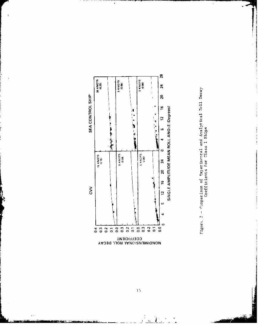
2 - Comparison of Experimental and Analytical Roll DecayCoefficients for Class I Ships ............... ...................... 15
3 - Comparison of Experimental and Analytical Roll DecayCoefficients for Class 2 Ships ..................... ...................... 16
4 - Comparison of Experimental and Analytical Roll DecayCoefficients for Class 3 Ships ............... ...................... 17
5 - Comparison of Experimental and Analytical Roll DecayCoefficients for Class 4 Ships ............... ....................... .. 21
6 - Actual Roll Decay Records from Model Experiments Withthe DE-1006, GM3 Without Bilge Keels ............. ................... .. 25
7 - Comparison Between Measured and Calculated (SM?) RollDecay Coefficients: Speed Effect for Various BilgeKeel Sizes for the DE-1006, GMI .............. ...................... .. 26
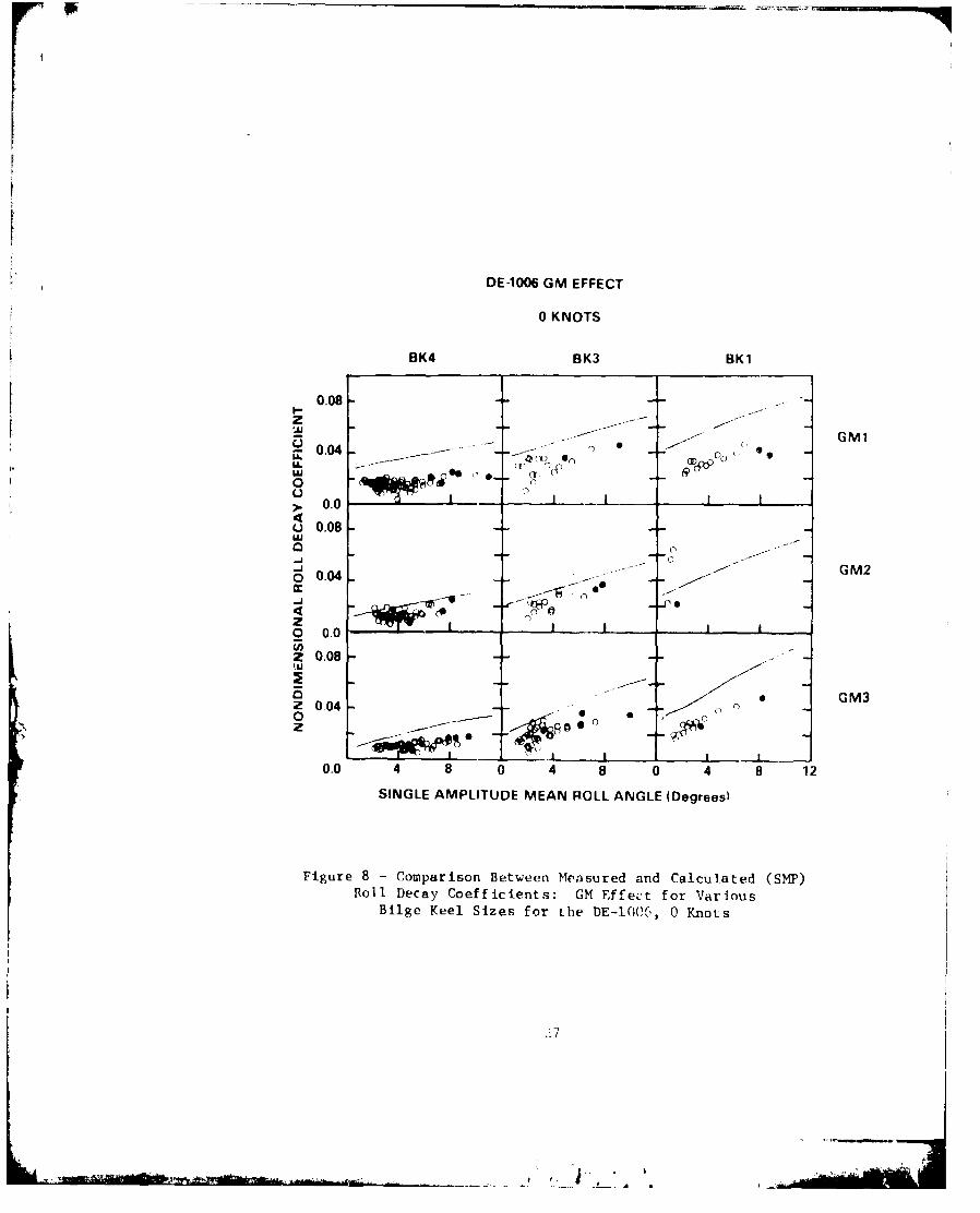
8 - Comparison Between Measured and Calculated (SMP) Roll
Decay Coefficients: GM Effect for Various BilgeKeel Sizes for the DE-1006, 0 Knots ............ .................... .. 27
lii
f .~

Page
9 - Components (Lift, Wavemaking, Skin Friction, etc.) of theCalculated Roll Deey Coefficient for the DE-1006, GM .... .......... 28
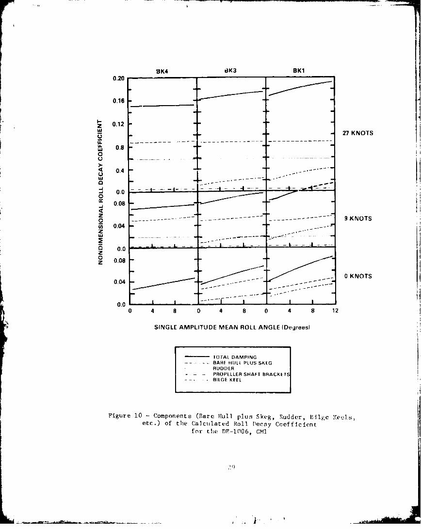
10 - Components (Bare Hull plus Skeg, Rudder, Bilge Keels, etc.)
of the Calculated Roll Decay Coefficient for the
DE-1006, . .1 . . . . . . . . . . . . . . . . . . . . . . . . . . . . . .. 29
Table I - Comparison of Ship Particulars ............ ................... ... 30
iv
1y*

ABSTPACT
Refinement in calculating the roll damping characteristicsof surface ships, particularly in the speed-dependent lift damp-ing terms, has significantly improved the prediction of lateralship motions. Incorporation of these refinements into the newrevised ship motion computer program has greatly enhanced theaccuracy and useful iess of the program. Validation of the rolldamping computations iR presented in this document through thecomparison of computer-predicted damping with model test datafor a number of ships. Relatively good agreement is found be-tween the analytical and experimental results.
ADMINISTRATIVE INFORMATION
The David W. Taylur Naval Ship Research and Deve.•opment Center (DTNSRDC) was au-
thorized and fundd over a period of years to perform this investigation. For fiscal
years 1977 and 1978, funding was provided by the Independent Exploratory Development
(TED) Program under Project Number 62766N and Block Number ZF-61-412-001, identified
at DTNSRDC as Work Unit 1568-124. For fiscal 1978, funding war also provided by the
Naval Sea Systems Command (NAVSEA) under Work Request 81650 and identified at DTNSRDC
aj Work Unit 1568-806. In addition, the Conventional Ship Seakeeping Research and
Development Program funded this investigation under Project Number 62543N, Block
Numbers SF-43-421-001 and SF-43-411-212 in 1978 and 1979, respectively. Work Unit
identification at DTNSP ' for this funding was 1504-100. Funding for 1980 was pro-
vided by the Ship Perf)rmance and Hydromechanics Program under Project Number 62543N,
Block Number ZF-43-421-001, identified as Work Unit 1500-104. Fiscal 1.981 work is
funded by the Sueface Ship Hydromechanics Program under Project Number 62543N, Block
Number SF--43-400-001, identified as Work Unit 1507-101.
INTRODUCTI ON
The David \4. Taylor Naval Ship Research and Development Center's Ship-Motion
and Sea-Load (SMS[,) Computer Program 1,2* has recently been completely revised. This
task was performed in order to provide a standard U.S. Navy Ship Motion Program
(SHP)** to all U.S. Navy research and development and design agencies. In addition,
this program was updated to improve basic computational procedures as well as to
enhance its usefulness as a ship design tool. One of the major improvements in the
new program is a significant increase in the accuracy of the roll motion predictions.
*A complete listing of references is given oat page 9.
**Meyers, W.G., T.R. Applebee and A.E. Baitis, "User's Manual for the Standard
Ship Motion Program, SMP," Report DTNSRDC/SPD-0936-01 to be published.

In order to validate the motions predicted by the SMSL program at various head-
ings, speeds, GM's, roll radii of gyration and bilge keel sizes, free-running model
experiments with the DE-1006 model were performed at DTNSRDC in the early 1970's.3
These experiments indicated that the roll damping calculated by the SMSL program
was inadequate, particularly at low GM's and high ship speeds. The subsequent
4analytical work of Schmitke found that the reason for this iiadequacy was the
neglect of the very important speed-dependent lift damping of the appendages, par-
ticularly for the rudders which had not been previously included in the calculations.
As a result, the newly revised SMP calculates the roll damping by a procedure
which also includes lift damping terms due to the hull and its appendages. Since
SMP can output all the component parts of the roll damping coefficients plus their
totals for any candidate ship, direct comparisons between the SMP-predicted roll
damping and the results from model test data are made herein.
Thirteen ships at various speeds, configurations and loading conditions are
compared.
SHIP PAP.TICI'LARS
The ships used in this investigation are divided into four classes:
i. Aviation ship hulls - the CVV and the Sea Control Ship (SCS);
2. Cruiser-type hulls - the CSGN with large waterplane (LWP) and conventional
waterplane area designs, and the CGN-42;
3. Destroyer/Frigate-type hulls - the DD-963, the FFG-7, the DE-1006, and the
USCG 270-ft Medium Endurance Cutter (WMEC);
4. Auxiliary hulls - the AOE, the AO-177, the T-ARC, and the MCM.
A listing of the hydrostatic characteristics of each ship is presented in Table 1
and Figure 1 contains the computer-drawn underwater hull shapes.
ANALYTICAL APPROACH
A major improvement in SMP is the inclusion of previously neglected but very
important, speed-dependent dynamic lift damping due to the hull and appendages. The
SMSL program's computational procedure for the roll damping coefficient, designatedasBT4 is defined as
TB 44 BE + BW
2

Here roll damping is treated as the sum of two terms, BE being roll angle dependent
(viscous) and BW being roll angle independent (potential). SMP calculates the roll
damping as the sum of three terms, where the third term, BL, represents the dynamic
lift damping of the hull and appendages. The roll damping coefficient is now defined
as
TB44 BE + BW + BL (2)
B is dependent on speed, the geometry and center of pressure of the lifting surface,L
and the location of the roll center. BW is calculated using potential theory in1,2
essentially the same fashion as was done in the older program. B is speed
independent though it is dependent upon the frequency of wave encounter. BE is
similarly calculated using the procedures of the old program with certain modifi-
cations due to more recent Japanese work. B is regarded as being dependent on
speed, roll angle, frequency, and ship or appendage geometry. the viscosity-related
damping is composed of the following components
BE - BBK + BSF x F 2(V) + [BHull + B Fpp F(V) (3)
BBK is the bilge keel damping calculated according to the expressions of Kato. 5
BSF is the damping due to hull skin friction and calculated in accordance with theSF 6
procedures of Kato; the function F2 (V) is the speed dependence of this skin friction2 7damping In accordance with Tamlya and Komura.
BHull is the eddymaking damping due to the hull calculate6 according to the
procedures of Tanaka8 with minor modifications. For the appendages, BApp represents
the flat plate eddymaking damping calculated using the empirical data of Hoerner.
The speed dependence of these two eddymaking damping components is introduced Ly
using the function F I(V) in accordance with the work of Ikeda, Himeno and Tanaka. 1 0
It is to be noted that the modular nature of SMP will simplify the anticipated
future changes in the calculation procedures for several of the roll damping compo-
nents as the theory becon :s more refined.
In calculating BL, the hull contribution is obtained by considering the entire
hull to be a very low aspect ratio foil, and each appendage contribution is calcu.-
lated separately. Here it should be mentioned that the appendafes considered are
bilge keels, skegs, rudders, fins and propeller shaft brackets. It should also be
3
|. ,. _

noted that the skegs are created as an integral part of the hull section for the
Tanakzi eddymaking damping calculations. However, they are treated as separate
appendages for purposes of dynamic lift damping calculations.
Examples of p.-edicted roll damping us5'-g this analytical procedure versus
experimental rill damping results from free-zunning model roll decay tests are pre-
sented in Figures 2 through 5.
EXPERIMENTAL DATA
A standard experimental procedure is used at DTNSRDC to investigate the roll
camping characteristics of surface ships. A free-running model experiment is per-
formed in calm water to determine the nondimensionai roll decay coefficient for
various mean roll angles. The details of the experiment are given below.
The self-powered model is brought up to a p-edetermined speed on a straight
course, restrained in sway, yaw and surge. The model is then released from all
cestraint, and roll motion is induced by pushing down on the side of the model. The
induced roll motion occurs at the natural roll frequency of the model and decreases
in magnitude in successive motion cycles. This decay of the motion is considered to
be representative of the total roll damping. Thus roll decay due to coupling between
roll. sway, and yaw is assumed to be negligible. A time history of the roll motion
that the model experiences is measured and recorded on an analog strip chart, such
as shown in Figure 6. This procedc.re is repeated for each speed over a range of
different Initial roll angles. The roll decay coefficient, n, is determined from
these analog records by the formula:
n = In (4)= 22
where 0I and 2 correspond to consecutive double amplitude roll angles (see Figure
6). Each value of n has a corresponding mean roll angle, 0, associated with it,
where
-- =i
= (01+2)/2] (5)
Simply stated, • is the average single amplitude roll angle. Then pairs 3f values,
n and 0, ran be plotted for comparison with analytical results as shown in Figuies 2
4

through 5. All of the experimental roll damping data shown represents roll damping
at the natural roll frequency.
It should be noted that sizable variations in the roll decay coefficient may
occur under conditions where roll angles are small or model speeds are high. Accu-
racy can be lost in both recording and analyzing small roll angles. At high speeds
(e.g., 20 knots full scale), only several cycles in the roll decay process car. be
obtained. Moreover, as speeds increase the ability to excite the model in roll
alone without inducing extraneous sway and yaw motions is greatly diminished. Often
only the first two cycles in the decay record can be considered reliable.
For these reasons, the roll decay coefficient corresponding to the initial two
roll decay cycles is regarded as the most accurate and dependable. These points
have been blackened in Figures 2 through 5.
The experiments to determine the roll damping charicteristics of the ships pre-
3ented in this report have been conducted over the years at DTNSRDC. The ships and
coriesponding references for the original data are as follows: CVV*, SCS*, CSCN12 13 3
("-~'2*, FG-7 , !MC1, AOE , AO-177*, and MCM*. The roll damping experiment for
tne T.-ARC was performed by Hydronautics, Inc.* Roll decay data for the DE-1006 and
DD-933 was provided from model experiments conducted by Baitis and Rossignol,
re.;rectively, both of DTNSRDC.
COMPARISON OF RESULTS
Comparisons between the calculated and measured roll damping characteristics of
the 13 ships investigated are made in Figures 2 through 5. Results are presented in
terms of the nondimensional roll decay coefficient as a function of the single
amplitude mean roll angle. This decay coefficient represents, in accordance with
the nomenclature of Cox and Lloyd,14 the ship damping moment per unit roll rate,
nondimensionalized by the product of twice the natural roll frequency and the total
mass moment of inertia of the ship about the roll axis. The experimental data,
represented by circles, are either darkened to indicate the decay coefficient
associated with the initial roll amplitude or open to indicate coefficient values
from subsequent roll amplitudes (see EXPERIMENTAL DATA, page 4). SMP-predicted roll
decay is represented by the solid line. Each plot for each ship has a speed, in
*Documents reporting tle results of roll damping (periments for these ships
have limited distribution.
-V -. I. J5

knots, and a Froude number, in parentheses, associated with it. In some cases, ex-
perimental. data may not be available. In the case of the T-ARC at 20 knots, no
data is available.
In general, good agreement is illustrated in these comparisons. The 8lope of
the roll damping with increasing roll angle is an indication cf the nonlinearity of
roll damping and is quite well predicted by theory. Tendencies are for the analyti-
cal results to overpredict the damping at lower speeds and to underpredict at the
higher speeds.
One outstanding exception is the case of the AO-177 in Figure 5. Predicted
roll damping grossly underestimates the measured data at every speed. Because this
is the only case of the 13 ships where the comparison suffers notably at all speeds,
it is felt that the original experimental data may be in error. This is supported
by the relatively large amount of damping measured for this ship which has no bilge
keels. A similar vessel, the AOE, as presented in Figure 5, demonstrates signifi-
cantly less danmping (on the order of one-half or less) than the AO-177 when tested
without bilge keels.
The effect of speed on the roll damping is presented for three different bilge
keel sizes, in Figure 7, for the DE-1006 at its nominal base GM of 12 percent of
beam. BK4 represents the hull without bilge keels, BK3 represents bilge keels with
an area of 1.25 percent of the wetted area of the hull, and BKI represents the
nominal base bilge keel with a 2.54 percent of wetted area size, These results are
shown for speeds of 0, 9, and 27 knots corresponding to Froude numbers of 0, 0.15,
and 0.46. The agreement between the slopes of the experimental and calculated roll
damping suggest that the roll angle dependent eddymaking damping, BE, is essentially
correct. Similarly, the growth of the damping with increasing speed which was not
present in the earlier program, where BL was i.eglected, appears to be reasonably
well represented.
The bilge keel effect at zero speed is presented for the three GM's in Figure 8.
The lift dependent damping BL is therefore zero in this figure. GMl represents the
nominal base value for the ship of 12 percent of beam, GM2 represents 9 percent of
beam value, and GM3 represents the smallest tested GM of 6.1 percent of beam. Again,
the eddymaking damping component BE alppears to be generally correct since tha
measured and calculated slopes agree. GM does not significantly affect these slopes
as expected, although bilge keel size does. As the bilge keels become larger, the
6

amount of eddymaking damping relative to the total damping increases, and thus the
nonlinearity of damping with roll angle increases.
The adequacy of the zoll angle independent damping term, BW, on the other hand,
is less certain since the agreement between the zero roll angle intercept value of
measured and calculated damping with CM is much poorcr. Note for example these
discrepancies for BKl.
Figures 9 and 10 were prepared to illustrate the values of various damping com-
ponents predicted by SIT es well as their sum. Both figures retain the same format
as Figure 7. Figure 9 illustrates the components of the computed damping in terms
of basic damping types, i.e., skin friction viscous damping, eddymaking damping
except for the bilge keel, bilge keel damping except for lift, and the wavemaking
damping. Figure 10, on the other hand, presents the damping provided individually
by the hull and skeg, the rudders, the pzopeller shaft brackets ind bilge keels.
The importance of the speed dependent and roll angle independent dynamic lift
damping, BL, as a portion of the total damping at even a relatively modest speed of
9 knots is quite well illustrated in Figure 9, as is the essentially insignificant
contribution of the skin friction. The impact of the speed dependence on the
eddymaking damping is also illustrated.
The relative importance of the hull and skeg as roll damping sources is illus-
trated in Figure 10 as is the insignificance, at least for the DE-1006, of the pro-
peller shaft brackets.
CONCLUDING REMARKS
The components of roll damping computed in S"? and considered in this report
are for "normal" ships. Certain components which are ignored as being insignificant
for "normal" ships should be recognized when nece ;sary; for example, wave damping
due to very large bilge keels mounted near to the free surface.
7
AM~

REFERENCES
1. Salvesen, N. et al., "Ship Motions ancd Sea Loads," Trans. Society of Naval
Architects and Marine Engineers, Vol. 78 (1970).
[2. Meyers, W.G. eL al., "NSRDC Ship Motion and Sea Load Computer Program,"
Naval Ship Research and Development Center Report 3376 (1975).
3. Baitis, A.E. and R. Wermter, "A Summary of Oblique Sea Experiments Conducted
at the Naval Ship Research and Development Center," UIth International Towing Tank
Conference (1972).
4. Schmitke, R.T., "Irediction of Wave-Induced Motions for Fallborne Hydro-
foils," Journal of Hydronautics, Vol. 11 (1977).
5. Kato, H., "Effect of Bilge Keels on the Rolling of Ships," Memories of the
Defence Academy, Japan, Vol. 4 (1966).
6. Kato, 1., "On the Frictional Resistance to the Roll of ShipF.," Journal of
the Society of Naval Architects of J.Tpan, Vol. 102 (1958).
7. Tamiya, S. and T. Komura, "Topics on Ship Rolling Characteristics with
Advpnce Speed," Journal of Zosen Kiokai, Society of Naval Architects of Japan, Vol.
132 (1972).
8. Tanaka, N., "A Study on the Bilge Keels (Part 4 - On the Eddy-Making
Resistance to the Rolling of a Ship Full)," Journal of the Society of Naval Archi-
tects of Japan, Vol. 109 (1960).
9. Hoerner, S.F., "Fluid Dynamic Drag," published by the authcr (1958).
10. Ikeda, Y. et al., "Components of Roll Damping of Ship at Forward Speed,"
Journal of the Society of N;,,)'-l Architects of Japan, Vol. 143 (1978).
11. Foley, E.W. and H.D. Jones, "Roll Stabili;-ation Investigation for the
Strike Cruiser (CSGN)," Repo.- T)TNSRDC/SPD-724-02 (Sep 1976).
12. Jones, H.D, and G.G. %ox, "Roll Stabilization Investigation for the Guided-
Missile Frigate (FFG-7)," Repoi:t DTNSRDC/SPD-495-18 (Jul 1976).
13. Foley, E.W. and H.D. Jones, "Preliminary Roll Stabilizer Sizing Predictions
for a U.S. Coast Guard E'!edium Endlurance Cutter (TMEC)," Repor: DTNSRDC/SPD-674-07
(Ncv 1976).
9
-~~.. .,*g .. . ...' I

14. Cox, G.G. and A.R. Lloyd, "Hydrodynamic Design Basis of Navy Ship Roll
Motion Stabilization," Trans. Sc~ciety of Naval Architects and Marine Engineers,
Vol. 85 (1977).
10
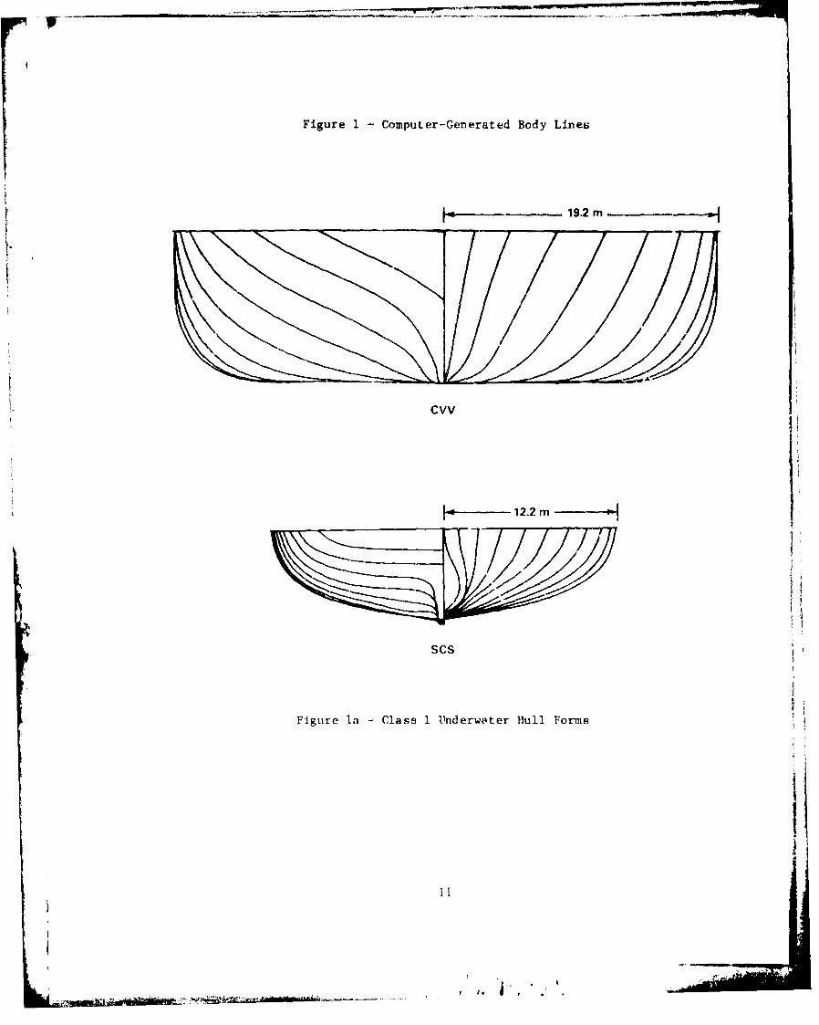
Figure 1I Computer-Generated Body Lines
La 19.2 m
cvv
12.2 m
scs
Figure la -Class 1 Underwater Ihull Forms

Figure I (Continued)
j~....11.6m
CSGN-CONVENTIONAL HULL
11.3 m
CSGN-LWP HULL
h-9.4 m 1
CGN-42
Figure lb -Class 2 Underwater Hull Forms
12

Figure 1 (Continued)
I---- 8.4 m
DD 963
t-k-- 6.9 m---
FFG 7
!.-5.6 m -'I1
DE-1006
USCG WMEC
Ftgure lc - C'ass 3 Underwater Bull Forms
I 3

Figure 1 (Continued)
- 16.5 m
AOE
13.4 m
AO-177
1 - 11.2 m
TARC
H-6.7 m
MCM
Figure Id - Class 4 Underwater Mill Forms
14
I'
~* . [
I--
0-. 00
o N~ CD
0
W 4)
wQw0
C:) Z
z0 v
L w ~~.4 L.
z~L)
CI
6D66Q0 0 00 0=0020 0DC'-
IN~31I+1300f3AV~OR 1101 IVNOISNIVYI(INON

OAI i 0 R 08
N U)
* S Ia I4-4
0~~ 0f r4 04L
Z -J
3e CD
0 ~* '-4
) II* B 0.
r-
coCw
Ini
Z0 0q
c 0)0 5 CD
0
161

00 - 0
03 z
0 4
01*4-4
0) - In -ý jI'O
0) F- m 0 0
> >%64
'-
0 -
co M
u 11 2
x x
CU D
coouI
x)0.
UN
cu 0
144 00
0i 0
00
I N ll:11 I 10):) AV:) M I IH I VNOISN IVYIOCNC)N
17

co zo m 0c
000z -z
I- co
CL 4)
2 0
IA wj
- -j
200
boN
0 0 0 rt 0 W
N 4.40
U) U) Z
ý4-
000
V M 0 AN 0 ) N cl 170 o D c 6 C o 00 oo 00 P
IN311-A-300 VOW 10H VNOIN3WI3N)
18-

10 0
CPC)
00S%
0
Q- W
NN
I 'IC6%J
0~ C-
uj w
Cn 0 C)
z -T w
C1
o44 cC
I-4-0
'n CD o UQa a C C 0P
IN11AU V3 I4 VOS3NOO
4<a- 19

x~ 0i0 Z N
0
Go z
0) 0) 0- in 0
o44
000
44
8 0 080r
C CH
U) U) U) 0 ý0 0 0 0 C
200


4)
co N0
SD I td
d diLai4 CD
0 0)
0 I-
0 co 0
0)4 N
z 4 0
8i I 0)H 0)
P4-
C) c
o. 080 z U-4
It 0
0-ii
CDI 0
zzJeý 0)
x~-r44Z
222

0 0 Al 0
w
ci z
A 0
0 0- 0Z z
(0 0 0
*i 0-J N
00
4 C, wo
.Aim

(12 a 1 COI~ 2 C2
p.-1
LL4J
-j
et w
c~.cc
w
CD
co 0
44-4
24 ý
r - ~ *

0 KNOTS
MV\NV\f~V\vvvNVVWV\AvvvA1--4 sec
9 KNI-TS
27 KNOTS
1 secF*-
j TIME
0
Figure 6 - Actual Roll Decay Records from Model FxperimentsWith the DE-IO06, GM3 Without Bilge Keels
25
/ I * '

I
DE-1006 SPEED EFFECT
BK4 BK3 BK10.20
016
(-)
z 0.12
LU - --- 27 KNOTSLLUj 0.08 0 -
< 0.04UjLU
0.0
.• 0.08 - C) - "S... ." c• ,o b 04 )Oct* 00
C) 0 9 KNOTS7 0.04
0.0 I I - I0z 0.08
*o*0 KNOTS0,04 - 00 e
0.0 r 7 i-
0 4 8 0 4 8 0 4 8 12
SINGLE AMPLITUDE MEAN ROLL ANGLE (Degrees)
t'.Kurc 7 - Compartson lietween Measured and Calcleated (S1I')PToll Decay (cefficicnts: Speed Fffect foi Various
Filge V-el Sizes for the DE-1006, (;Y1
26
-- -. . . ' A . .. ,-,;it• ••
DE-1006 GM EFFECT
0 KNOTS
BK4 BK3 BK1
0.08 -G
,.u • ./ -- - / -J ,:•G M 1
0.04
0 d, 0.0 8_I
0 .4Z 0.08o o....
kC)
-J 0- . GM2
o 0.04
I !0 0.08Z~~ 00 Y 6
0.0 4 8 0 4 8 0 4 8 12
SINGLE AMPLITUDE MEAN POLL ANGLE (Degrees)
Figure 8 - Comparison Between Measured and Calculated (SMP)Roll Decay Coefficients: GM Effect for Various
Bilge Keel Sizes for Lhe DE-lOt('!, 0 Knots
,'7
I t.

0K4 BK3 BK10.20 .,-
0.16-
I-I
z 0.12
3 27 KNOTSLA.w 0.080
S0.04
o~ o~o
-j 0.08
zo 9 KNOTS0 0.04 -_•--..
z ._ ....------------------oI. .~ - .. ..... .... • ............... _ a_
o 0.08z
0 KNOTS0.04
---------------- , ------- --------------
0.0~~~~. .En~.~m~utm .-~ ....0 4 0 4 8 0 4 8 12
SINGLL AMP' 'JDE MEAN ROLL ANGLE (Degrees)
1OJAL DAMPIN(G
LIFIT
- ----- WAV MAKIN(G
SKIN FRICTION
FUDYMAKING WITHOUT BILGE KEELSHILUF KIFL EDDYMAKING
Figure 9 - Components (Lift, Wavemaking, Skin Friction, etc.) ofthe Calculated Poll Dlecay Coefficient for '.±z DE-1006, CM]
28

COl c-, . D0 0 0 0 0 0 0CC 01
I_- CA Cl C C
CLu , ' 0 0 00 0 0 o - 0
C' I,) In, In 'D In n' r
"" t: 22. I In
' -
In In t o (- a
a-i"a a Ca a) c a, (oa Ca CD S) It) .i .
m. o . . . 0- Ico OD ,-N ,a. , a aaaa..a . a-
aea .e C 0N~ '- 0 CD r'. am o
m- n
a'-~~~~~~~7 CDC - a C a . 0 JB < a '
a- .,,,C' (C a '. C',. C C
ca wC - In In 0 -7 C r Ca C
c) 00 "' In Ca L
'o IV.-C - CoC . - C
C oC CC
-. _ __ _ __ _ _ _ _ _ _ _ _ __30__ _ _

DTNSRDC ISSUES THREE TYPES OF REPORTS
1. DTNSRDC REPORTS, A FORMAL SERIES, CONTAIN INFORMATION OF PERMANENT TECHNICAL VALUE. THEY CARRY A CONSECUTIVE NUMERICAL IDENTIFICATION REGARDLESS OFTHEIR CLASSIFICATION OR THE ORIGINATING DEPARTMENT.
2. DEPARTMENTAL REPORTS, A SEMIFORMAL SERIES, CONTAIN INFORMATION OF A PRELIM.INARY, TEMPORARY, OR PROPRIETARY NATURE OR OF LIMITED INTEREST OR SIGNIFICANCE.THEY CARRY A DEPARTMENTAL A.LPHANUMER'CAL IDENTIFICATION.
3. TECHNICAL MEiMUHANDA, AN INFORMAL SERIES, CONTAIN TECHNICAL DOCUMENTATIOA'OF LIMITED USE AND INTEREST. THEY ARE PRIMARILY WORKING PAPERS INTENDED FOR INTERNAL USE. THEY CARRY AN IDENTIFYING NUMBER WHICH INDICATES THEIR TYPE AND THENUMERICAL CODE OF THE ORIGINATING DEPARTMENT. ANY DISTRIBUTION OUTSIDE DTNSRDCMUST BE APPROVED BY THE HEAD OF THE ORIGINATING DEPARTMENT ON A CASE-BY.CASEBASIS.