M ANUALE T ECNICO ANDBOOK - stock-dent.ru
62
1 MANUALE TECNICO SUPPORTO TECNICO PER COMPRESSORI A SECCO TECHNICAL HANDBOOK TECHNICAL SUPPORT FOR OILLESS COMPRESSORS VERSIONE 1 PRODUZIONE FINO A MATR. N°10153699 VERSION 1 PRODUCTIONS TILL S/N 10153699 Via Pascoli 15, ABBIATEGRASSO (MI) Italia Tel: +39 029019180-680-253 Fax: +39 029019273 www.mgfcompressors.com e-mail info: [email protected] e-mail service: [email protected] Rev. 7.2 del 05/2013
Transcript of M ANUALE T ECNICO ANDBOOK - stock-dent.ru

1
MANUALE TECNICO SUPPORTO TECNICO PER COMPRESSORI A SECCO
TECHNICAL HANDBOOK TECHNICAL SUPPORT FOR OILLESS COMPRESSORS
VERSIONE 1 PRODUZIONE FINO A MATR. N°10153699 VERSION 1 PRODUCTIONS TILL S/N 10153699
Via Pascoli 15, ABBIATEGRASSO (MI) Italia
Tel: +39 029019180-680-253 Fax: +39 029019273
www.mgfcompressors.com e-mail info: [email protected]
e-mail service: [email protected]
Rev. 7.2 del 05/2013

MANUALE TECNICO – TECHNICAL HANDBOOK: COMPRESSORI DENTALI A SECCO - OILLESS DENTAL COMPRESSORS
2
Indice – Index
1 COMPRESSORI A SECCO PRIME – PRIME OILLESS COMPRESSORS.................................................. 3 1.1 ESPLOSO COMPRESSORE DA 0,75 KW – 0,75 KW COMPRESSOR DRAWING ...................................................... 5 1.2 ELENCO RICAMBI 0,75 KW PRIME – SPARE PART LIST 0,75 KW PRIME ....................................................... 6 1.3 ESPLOSO COMPRESSORE DA 1,5 KW – 1,5 KW COMPRESSOR DRAWING .......................................................... 7 1.4 ELENCO RICAMBI 1,5 KW PRIME – SPARE PART LIST 1,5 KW PRIME .......................................................... 8 1.5 ESPLOSO COMPRESSORE PRIME ESTRUSO DA 1,5 KW – 1,5 KW COMPRESSOR EXTRUDED PRIME DRAWING ................................................................................................................................................................ 9 1.6 ELENCO RICAMBI 1,5 KW PRIME ESTRUSO – SPARE PART LIST 1,5 KW EXTRUDED PRIME ...................10 1.7 ESPLOSO COMPRESSORE DA 2,2 KW – 2,2 KW COMPRESSOR DRAWING .........................................................11 1.8 ELENCO RICAMBI 2,2 KW PRIME – SPARE PART LIST 2,2 KW PRIME ..........................................................12
2 COMPRESSORI A SECCO TOP AIR – OILLESS TOP AIR COMPRESSORS 0,65 KW – 1.400, 2.800 GIRI13
2.1 TOP AIR OILLESS COMPRESSORS 0,65 KW DRAWING – 1.400 AND 2.800 RPM ...............................................15 2.2 LISTA RICAMBI – SPARE PART LIST ..............................................................................................................16
3 COMPRESSORI GENESI DA 0,55 E 1,1 KW - GENESI COMPRESSORS 0,55 AND 1,1 KW .....................18 3.1 ESPLOSO COMPRESSORE GENESI – GENESI DRAWING ...............................................................................19 3.2 ELENCO RICAMBI 0,55 KW GENESI – SPARE PART LIST 0,55 KW GENESI ..................................................20 3.3 ELENCO RICAMBI 1,1 KW GENESI – SPARE PART LIST 1,1 KW GENESI ......................................................21
4 ESPLOSI GENERALI – GENERAL EXPLOADED DRAWINGS ..................................................................22 4.1 GENESI LINE - 24 LITRES VERSIONS ...........................................................................................................22 4.2 GENESI LINE - 30 LITRES VERSIONS ..........................................................................................................23 4.3 KIT ESSICCAZIONE GENESI – GENESI DRYER KIT TA-ES-103-K1B ...........................................................25 4.4. GENESI LINE - 50 LITRES VERSIONS ..........................................................................................................26 4.5. PRIME 1 LINE - 30 LITRES VERSIONS ..........................................................................................................28 4.6. KIT ESSICCAZIONE PRIME 1 – PRIME 1 DRYER KIT TA-ES-103-K1 ............................................................29 4.7. PRIME 2 LINE - 30 LITRES VERSIONS ..........................................................................................................30 4.8. KIT ESSICCAZIONE PRIME 2-3 – PRIME 2-3 DRYER KIT TA-ES-101-K1......................................................31 4.9. PRIME 2-3 LINE - 50 LITRES VERSIONS .......................................................................................................32 4.10. PRIME LINE - 100 LITRES VERSIONS ...........................................................................................................35 4.11. KIT ESSICCAZIONE PRIME TANDEM – PRIME TANDEM DRYER KIT TA-ES-102-K1 ...............................36 4.12. ESPLOSO DELL’ASSEMBLATO CS E SKY– CS AND SKY ASSEMBLY DRAWING ..............................................41 4.13. ELENCO RICAMBI LINEA TOP AIR – TOP AIR LINE SPARE PARTS LIST .........................................................44
5 GRAFICI DI PORTATA – AIR FLOW DATASHEET ..................................................................................46 5.1 VERSIONI 0,75 KW, 1,5 KW E 2,2 KW PRIME – VERSIONI 0,45 KW E 0,65 KW TOP AIR - VERSIONS 0,75 KW, 1,5 KW E 2,2 KW PRIME – VERSIONS 0,45 KW AND 0,65 KW TOP AIR ..........................................................46 5.2 VERSIONI 0,55 KW E 1,1 KW NUOVO GENESI – 0,55 KW AND 1,1 KW NEW GENESI VERSIONS ..................47
6 MANUTENZIONE COMPRESSORI A SECCO – OILLESS COMPRESSORS MAINTENANCE (PRIME AND GENESI VERSIONS) ......................................................................................................................................48
6.1 OPERAZIONI DI MANUTENZIONE ORDINARIA – ORDINARY MAINTENANCE OPERATIONS..................................48 6.2 OPERAZIONI DI MANUTENZIONE STRAORDINARIA – EXTRA-ORDINARY MAINTENANCE OPERATIONS ..............50 6.3 KIT RICAMBI PER MANUTENZIONE COMPRESSORI MGF – SPARE PARTS KIT FOR MGF COMPRESSORS MAINTENANCE .......................................................................................................................................................53 6.4 REGOLAZIONE DEL PRESSOSTATO – PRESSURE SWITCH CALIBRATION ...........................................................55 6.5 CONDIZIONI OPERATIVE DELL’ESSICCATORE A MEMBRANA – MEMBRANE AIR DRYER OPERATING .................56 6.6 CONDIZIONI OPERATIVE DELL’ESSICCATORE AD ADSORBIMENTO – ADSORPTION AIR DRYER OPERATING .......57 6.7 COMPONENTISTICA E KIT DI ESSICCAZIONE - MGF AIR DRYERS COMPONENTS AND AVAILABLE KITS ..............59 6.8 SETTAGGIO DELLO SCARICO AUTOMATICO DI CONDENSA – AUTOMATIC DRAIN SETTING ................................61

MANUALE TECNICO – TECHNICAL HANDBOOK: COMPRESSORI DENTALI A SECCO - OILLESS DENTAL COMPRESSORS
3
1 Compressori a secco PRIME – PRIME Oilless compressors

MANUALE TECNICO – TECHNICAL HANDBOOK: COMPRESSORI DENTALI A SECCO - OILLESS DENTAL COMPRESSORS
4

MANUALE TECNICO – TECHNICAL HANDBOOK: COMPRESSORI DENTALI A SECCO - OILLESS DENTAL COMPRESSORS
5
1.1 Esploso compressore da 0,75 kW – 0,75 kW compressor drawing

MANUALE TECNICO – TECHNICAL HANDBOOK: COMPRESSORI DENTALI A SECCO - OILLESS DENTAL COMPRESSORS
6
1.2 Elenco ricambi 0,75 kW PRIME – Spare part list 0,75 kW PRIME Come utilizzare l’elenco ricambi:
1. Consultare l’esploso per individuare il componente necessario 2. Il numero in figura indica la posizione (POS.), riportata nella prima colonna della tabella. 3. La colonna quantità indica quanti pezzi del relativo codice sono utilizzati per compressore. 4. Le righe evidenziate in giallo rappresentano i ricambi raccomandati
How to read the spare part list:
1. Check the drawing to find required component 2. The number in the drawing indicates the position (POS.) and it is mentioned in the first
column of the list below. 3. Q.ty column indicates the number of components required for one compressor. 4. Yellow lines are recommended spare parts
POS. CODICE CODE DENOMINAZIONE
DESCRIPTION
Q.TA' Q.TY
1 MA-MT-001 MOTORE ELETTRICO 1HP ELECTRIC MOTOR 1 HP 1 4 MA-MG03000-L CILINDRO CON CANNA OTTONE CYLINDER COMPLETE 1 5 MG-MI-010 VITE TCCE M8 x 30 - UNI 5931 SCREW UNI 5931 M8X30 6 7 MA-PC004 VENTOLA MEC 90 COOLING FAN MEC 90 2 8 MA-MG00010 SUPPORTO CONVOGLIATORE CONVEYOR SUPPORT 2 9 MA-CO-003 CONDENSATORE 32 µF CAPACITOR 32 µF 1
10 MA-MG00023 COPRIVENTOLA MONOCILINDRICO CON FILTRO
COOLING FAN CASING MONOCYLINDRICAL WITH FILTER 1
11 MA-MG01005 CONVOGLIATORE LATERALE MONO LATERAL CONVEYOR MONO 1 12 MA-MF00010 FILTRO ARIA ASPIRATION FILTER 1 13 MG-MI-018 VITE AUTOFORM. M6x25 Taptipe SCREW M6X25 TAPTYPE 8 14 MA-MG03003-C IMBIELLAGGIO COMPLETO CON PISTONE COMPLETE CONNECTING ROD WITH PISTON 1 19 MA-MG00001 SEGMENTO COMPRESSIONE PISTON RING 1 20 MA-MG00003 FASCIA GUIDA PISTONE PISTON ADJUSTABLE RING 1 21 MA-MG00006-L SEMICARTER P.FUSO LATO VENTOLA 1 HP CASING COOLING FAN SIDE 1 HP 1 22 MA-MG00006-L SEMICARTER P.FUSO LATO VENTOLA 1 HP CASING COOLING FAN SIDE 1 HP 1 23 MG-MI-014 SPINA CILINDRICA DIN 7 - 4h8 x 10 CYLINDRICAL PIN DIN 7 - 4h8 x 10 2 24 MG-MI-012 DADO ESAGONALE M8 UNI 5587 Zincato EXAGONAL NUT M8 7 25 MA-MG01008-1-L FLANGIA CARTER PRESSOFUSO CASING FLANGE 1
26 MA-MG00022 COPRIVENTOLA MONOCILINDRICO SENZA FILTRO
COOLING FAN CASING MONOCYLINDRICAL WITHOUT FILTER 1
28 MA-MG01010-N TIRANTE MOTORE ELETTRICO 1 HP PRESS. TIE ROD FOR 1 HP ELECTRIC MOTOR PRES. 4 29 MA-MG02002-C PIASTRA VALVOLARE COMPLETA COMPLETE VALVE PLATE 1 35 MA-PC018 O.RING 2250 VITON O.RING 2250 VITON 2 36 MA-MG-00015-LR TESTA CILINDRO DESTRA RIGHT CYLINDER HEAD 1 40 MA-MG00014-1 BOCCOLA SERR. CUSCIN. BEARING FIXING BUSH 1 41 MG-MI-009 VITE FISSAGGIO TESTA TCCE M8x75 zincata SCREW UNI 5931 M8X75 4 44 VT-TSE-003 VITE UNI 5931 M8 x 20 SCREW UNI 5931 M8 x 20 4 48 VT-RND-002 RONDELLA DENTELLATA D=8 WASHER D=8 1 49 MG-TA-002 BOCCOLA PORTA VENTOLA COOLING FAN FIXING BUSH 1 50 MA-TATR005 BOCCOLA DI CENTRATURA CARTER CASING CENTERING BUSH 2 54 MA-MG00024 ANELLO DI ESPANSIONE DEL SEGMENTO ELASTIC RING 1 55 MA-TU-005 TUBO ASPIRAZIONE ASPIRATION PIPE 1 56 RA-AL-001 RACCORDO A L MM 3/8'' PIPE FITTING L MM 3/8 1
MG-TA-001 DISTANZIALE GENESI7PRIME SPACER GENESI/PRIME 1

MANUALE TECNICO – TECHNICAL HANDBOOK: COMPRESSORI DENTALI A SECCO - OILLESS DENTAL COMPRESSORS
7
1.3 Esploso compressore da 1,5 kW – 1,5 kW compressor drawing

MANUALE TECNICO – TECHNICAL HANDBOOK: COMPRESSORI DENTALI A SECCO - OILLESS DENTAL COMPRESSORS
8
1.4 Elenco ricambi 1,5 kW PRIME – Spare part list 1,5 kW PRIME Come utilizzare l’elenco ricambi:
1. Consultare l’esploso per individuare il componente necessario 2. Il numero in figura indica la posizione (POS.), riportata nella prima colonna della tabella. 3. La colonna quantità indica quanti pezzi del relativo codice sono utilizzati per compressore. 4. Le righe evidenziate in giallo rappresentano i ricambi raccomandati
How to read the spare part list: 1. Check the drawing to find required component 2. The number in the drawing indicates the position (POS.) and it is mentioned in the first
column of the list below. 3. Q.ty column indicates the number of components required for one compressor. 4. Yellow lines are recommended spare parts
POS. CODICE CODE
DENOMINAZIONE
DESCRIPTION
Q.TA' Q.TY
1 MA-MT-004 MOTORE ELETTRICO 2 HP ELECTRIC MOTOR 2 HP 1 4 MA-MG03000-L CILINDRO CON CANNA OTTONE CYLINDER COMPLETE 2 5 MA-MG00001 SEGMENTO COMP. PISTON RING 2 7 MA-PC008 VENTOLA MEC 100 COOLING FAN MEC 100 2 8 MA-MG00010 SUPPORTO CONVOGLIATORE CONVEYOR SUPPORT 4 9 MA-MG00021 COPRIVENTOLA LATO MOTORE EL. 2 HP COOLING FAN CASING EL. MOTOR SIDE 2 HP 1 10 MA-MG01003 CONVOGLIATORE LATERALE LATERAL CONVEYOR 2 11 MA-MF00010 FILTRO ARIA ASPIRATION FILTER 2 12 MG-MI-018 VITE AUTOFORMANTE M6 x 25 SCREW M6X25 TAPTYPE 8 13 MA-MG00008-L SEMICARTER 2 CILINDRI LATO VENTOLA CASING COOLING FAN SIDE 1 14 MA-MG01008-1-L FLANGIA CARTER PRESSOFUSO CASING FLANGE 1 16 MA-MG00020 COPRIVENTOLA LATO CILINDRI COOLING FAN CASING CYLINDER SIDE 2 HP 1 17 MG-MI-009 VITE FISSAGGIO TESTA TCCE M8x75 zincata SCREW UNI 5931 M8X75 8 18 MG-MI-010 VITE TCCE-UNI 5931 M8 x 30 SCREW UNI 5931 M8X30 6 19 MA-MG01002-N TIRANTE MOTORE ELETTRICO 2 HP TIE ROD FOR 2 HP ELECTRIC MOTOR 4 20 MA-MG00014-1 BOCCOLA CENTRAGGIO CUSCIMNETTO BEARING CENTERING BUSH 1 21 MA-MG00008-L SEMICARTER P.FUSO LATO VENTOLA CASING COOLING FAN SIDE 1 22 MG-TA-006 BOCCOLA PORTA VENTOLA COOLING FAN FIXING BUSH 1 23 MA-MG00015-LR TESTA CILINDRO DESTRA RIGHT CYLINDER HEAD 1 27 MA-MG03003-C IMBIELLAGGIO COMPLETO CON PISTONE COMPLETE CONNECTING ROD WITH PISTON 2 31 MA-CO-002 CONDENSATORE 45 mF CAPACITOR 45 mF 1 32 MG-MI-012 DADO ESAGONALE M8 UNI 5587 Zincato EXAGONAL NUT M8 8 37 MG-MI-011 VITE TCCE-UNI 5931 M8 x 20 SCREW UNI 5931 M8X20 4 38 MA-MG00003 FASCIA GUIDA PISTONE PISTON ADJUSTABLE RING 2 39 MA-MG00024 ANELLO ESPANSIONE SEG. ELASTIC RING 2 40 MA-MG02002-C PIASTRA VALVOLARE COMPLETA COMPLETE VALVE PLATE 2 46 MA-PC018 O.RING 2250 VITON O.RING 2250 VITON 4 47 MA-MG-00015-LL TESTA CILINDRO SINISTRA LEFT CYLINDER HEAD 1 48 MA-TATR005 BOCCOLA CENTRATURA CARTER CASING CENTERING BUSH 2 49 MG-MI-013 VITE UNI 5931 M8 x 40 SCREW UNI 5931 M8 x 40 1 50 MG-MI-014 SPINA CILINDRICA DIN 7 - ø4 x 8 PARALLEL PIN Ø4X8 4 51 VT-RND-002 RONDELLA DENTELLATA D=8 WASHER D=8 1 56 MG-SP-001 SPINA CILINDRICA ø8x30 PARALLEL PIN Ø8X30 1 57 RA-AT-044 RACCORDO A T MMM 3/8 PIPE FITTING T MMM 3/8 1 58 MA-TU-002 TUBO DIAM. 12 F/F 3/8. PIPE ø12 FF3/8 1 59 RA-AL-001 RACCORDO A L MM 3/8'' PIPE FITTING L MM 3/8 1 60 MA-TU-003 TUBO DI ASPIRAZIONE ø14 CORTO F1/2 SHORT ASPIRATION PIPE ø14 F1/2 1 61 MA-TU-004 TUBO DI ASPIRAZIONE ø14 LUNGO F1/2 LONG ASPIRATION PIPE ø14 F1/2 1

MANUALE TECNICO – TECHNICAL HANDBOOK: COMPRESSORI DENTALI A SECCO - OILLESS DENTAL COMPRESSORS
9
1.5 Esploso compressore PRIME ESTRUSO da 1,5 kW – 1,5 kW compressor EXTRUDED PRIME drawing

MANUALE TECNICO – TECHNICAL HANDBOOK: COMPRESSORI DENTALI A SECCO - OILLESS DENTAL COMPRESSORS
10
1.6 Elenco ricambi 1,5 kW PRIME ESTRUSO – Spare part list 1,5 kW EXTRUDED PRIME
Come utilizzare l’elenco ricambi: 1. Consultare l’esploso per individuare il componente necessario 2. Il numero in figura indica la posizione (POS.), riportata nella prima colonna della tabella. 3. La colonna quantità indica quanti pezzi del relativo codice sono utilizzati per compressore. 4. Le righe evidenziate in giallo rappresentano i ricambi raccomandati
How to read the spare part list:
1. Check the drawing to find required component 2. The number in the drawing indicates the position (POS.) and it is mentioned in the first column of the list below. 3. Q.ty column indicates the number of components required for one compressor. 4. Yellow lines are recommended spare parts
POS. CODICE CODE DENOMINAZIONE DESCRIPTION Q.TA' Q.TY
1 MA-MT-004 MOTORE ELETTRICO 2HP ELECTRIC MOTOR 2HP 1
3 MA- CO-002 CONDENSATORE 45 mF CAPACITOR 45mF 1
5 MG-MI-013 VITE UNI 5931 M8 X 40 SCREW UNI 5931 M8 X 40 1
7 MG-SP-001 SPINA CILINDRICA ø8X30 PARALLEL PIN ø8X30 1
10 MA-PC008 VENTOLA MEC 100 COOLING FAN MAC 100 2
13 MG-MI-012 Dado esagonale M8 UNI 5587 ZINCATO EXAGONAL NUT M8 6
23 MA-MG040308-CBO CARTER COMPLESSIVO ESTRUSO CASING COMPLETE EXTRUDED 1
24 MA-MG00020 COPRIVENTOLA LATO CILINDRI 1,5 kW COOLING FAN CASING CYLINDER SIDE 1,5kW 1
25 MG-MI-018 VITE AUTOFORMANTE M6X30 SCREW M6X30 TAPTYPE 8
28 MA-MF00010 FILTRO ASPIRAZIONE ASPIRATION FILTER 2
29 MG-TA-006 BOCCOLA PORTAVENTOLA COOLING FAN FIXING BUSH 1
30 VT-RND-002 RONDELLA DENTELLATA ø8 WASHER D=8 1
31 MA-MG01006-N TIRANTE MOTORE ELETTRICO 2 HP ESTR. TIE ROD FOR 2 HP ELECTRIC MOTOR EXTR. 4
33 MA-MG01008-1-L FLANGIA ESTERNA CARTER EXTERNAL CALOTTE FLANGE 1
34 MA-MG00014-1 BOCCOLA CENTRAGGIO CUSCINETTO BEARING CENTERING BUSH 1
35 MA-MG00021 COPRIVENTOLA LATO MOTORE ELETTRICO COOLING FAN CASING ELECTR.MOT.SIDE 1,5 1
43 MA-MG-01003 CONVOGLIATORE LATERALE LATERAL CONVEYOR 2
44 MG-MI-009 VITE FISSAGGIO TESTA ZINCATA GALV. HEAD SCREW 8
45 MA-MG00015-LL TESTA CILINDRO SINISTRA LEFT CYLINDER HEAD 1
46 MA-MG00015-LR TESTA CILINDRO DESTRA RIGHT CYLINDER HEAD 1
55 MA-MG00010 SUPPORTO CONVOGLIATORE CONVEYOR SUPPORT 4
59 MG-MI-014 SPINA CILINDRICA ø4X8 PARALLEL PIN ø4X8 4
61 MA-MG00003 FASCIA GUIDA PER PISTONE PISTON ADJUSTABLE RING 2
62 MA-MG03003-C IMBIELLAGGIO COMPLETO CON PISTONE COMPLETE CONNECTING ROD WITH PISTON 2
65 MA-MG03000-L-ES CILINDRO CON CANNA OTTONE ESTRUSO CYLINDER COMPLETE 2
66 MA-MG00001 SEGMENTO COMPRESSIONE PISTON RING 2
67 MA-MG00024 ANELLO ESPANSIONE SEG. ELASTIC RING 2
69 MA-MG02002-C PIASTRA VALVOLARE COMPLETA COMPLETE VALVE PLATE 2
74 MA-PC018 O-RING TENUTA P.V. VALVE PLATE O-RING 4
75 RA-AT-044 RACCORDO A T MMM 3/8 PIPE FITTING T MMM 3/8 1
76 MA-TU-002 TUBO DIAM. 12 F/F 3/8. PIPE ø12 FF3/8 1
77 RA-AL-001 RACCORDO A L MM 3/8'' PIPE FITTING L MM 3/8 1
78 MA-TU-003 TUBO DI ASPIRAZIONE ø14 CORTO F1/2 SHORT ASPIRATION PIPE ø14 F1/2 1
79 MA- TU-004 TUBO DI ASPIRAZIONE ø14 LUNGO F1/2 LONG ASPIRATION PIPE ø14 F1/2 1

MANUALE TECNICO – TECHNICAL HANDBOOK: COMPRESSORI DENTALI A SECCO - OILLESS DENTAL COMPRESSORS
11
1.7 Esploso compressore da 2,2 kW – 2,2 kW compressor drawing

MANUALE TECNICO – TECHNICAL HANDBOOK: COMPRESSORI DENTALI A SECCO - OILLESS DENTAL COMPRESSORS
12
1.8 Elenco ricambi 2,2 kW PRIME – Spare part list 2,2 kW PRIME Come utilizzare l’elenco ricambi:
1. Consultare l’esploso per individuare il componente necessario 2. Il numero in figura indica la posizione (POS.), riportata nella prima colonna della tabella. 3. La colonna quantità indica quanti pezzi del relativo codice sono utilizzati per compressore. 4. Le righe evidenziate in giallo rappresentano i ricambi raccomandati
How to read the spare part list:
1. Check the drawing to find required component 2. The number in the drawing indicates the position (POS.) and it is mentioned in the first column of
the list below. 3. Q.ty column indicates the number of components required for one compressor. 4. Yellow lines are recommended spare parts
POS. CODICE CODE DENOMINAZIONE DESCRIPTION Q.TA' Q.TY
1 MA-MT-008 MOTORE ELETTRICO 3HP 230V-50HZ ELECTRIC MOTOR 3HP 230V-50HZ 1
1 MA-MT-010 MOTORE ELETTRICO 3HP 400V ELECTRIC MOTOR 3HP 400 V 1
4 MA-MG03000-L CILINDRO CON CANNA OTTONE CYLINDER COMPLETE 3
5 MA-MG00001 SEGMENTO COMPRESSIONE PISTON RING 3
7 MA-PC009 VENTOLA MEC 112 + ANELLO DI FISSAGGIO COOLING FAN + FAN RING 2
7 MA-PC008 VENTOLA MEC 100 + ANELLO DI FISSAGGIO MOTORE ELETTRICO
COOLING FAN ELECTRIC MOTOR SIDE + FAN RING
8 MA-MG00010 SUPPORTO CONVOGLIATORE CONVEYOR SUPPORT 2
9 MA-MG00023 COPRIVENTOLA MONOC. CON FILTRO COOLING FAN CASING WITH FILTER 1
10 MA-MG01012 CONVOGLIATORE LATERALE PRIME 3 CIL. LATERAL CONVEYOR 1
11 MA-MF00010 FILTRO ASPIRAZIONE LINEA PRIME-GENESI ASPIRATION FILTER 1
12 MG-MI-018 VITE AUTOMASC. M6x30 SCREW TAPTYPE M6x30 8
13 MA-MG00011-L SEMICARTER 3 CILINDRI LAVORATO CASING 2
14 MA-MG01008-1-L FLANGIA POSTERIORE BACK FLANGE 1
15 MG-TA-005 ANELLO EQUILIBRATORE 3 CIL COUNTERWEIGHT 2
16 MA-MG00027 COPRIVENTOLA 3 CIL. SENZA FILTRO COOLING FAN CASING, NO FILTER 1
17 MG-MI-009 VITE M8X75 UNI5931 SCREW TCCE M8X75 UNI5931 12
18 MG-MI-010 VITE TCCE M8X30 ZINCATA UNI5931 SCREW VITE TCCE M8X30 UNI5931 6
19 MA-MG01011-N TIRANTE X MOT.EL.PRIME 3HP NICHELATO TIE ROD FOR 3 HP ELECTIC MOTOR 4
20 MA-MG00016-1 BOCCOLA CENTRAGGIO CUSCINETTO BEARING CENTERING BUSH 1
22 MG-TA-002 BOCCOLA BLOCC.CUSC. E PORTAVENTOLA BEARING FIXING BUSH 1
23 MA-MG00015-LR TESTA CIL. LAVORATA DX RIGHT CYLINDER HEAD 2
27 MA-MG03003-C1 IMBIELLAGGIO PRIME COMPLETO CON PISTONE COMPLETE CONNECTING ROD WITH PISTON 3
31 MG-CO-003 CONDENSATORE DA 50 MF CAPACITOR 50MF 1
32 MG-MI-012 DADO ESAGONALE M8 UNI 5587 ZINCATO EXAGONAL NUT M8 7
38 MA-MG00003 FASCIA GUIDA PER PISTONE G 456 CARBOGRAFITE PISTON ADJUSTABLE RING 3
39 MA-MG00024 ANELLO DI ESPANSIONE SEGMENTO ELASTIC RING 3
40 MA-MG02002-C PIASTRA VALVOLARE COMPLETA VALVE PLATE 3
46 MA-PC018 O-RING 2250 VITON TENUTA TESTA - CIL O.RING2250 VITON 3
47 MA-MG00015-LL TESTA CIL. LAVORATA SX LEFT CYLINDER HEAD 1
48 MA-TATR005 BOCCOLA CENTRATURA CARTER CASING CENTRING BUSH 2
50 MG-MI-014 SPINA CILINDRICA DIN 7 – 4h8 X 8 CYLINDRICAL PIN DIN 7 -4H8 X 8 6
51 VT-RND-002 RONDELLA DENTELLATA D.8 Tab kasher ø8 1
52 MG-SI-003 ECCENTRICO FERRO SINT 17X50X17 3 CIL. ECCENTRIC 5
53 RA-TA-017 TAPPO FEMMINA CILINDRICO 1_2 Screw plug ½” 2
54 MG-TA-003 DISTANZIALE BIELLA PRIME 3 CIL Spacer 1
57 VT- TSE-003 VITE ESAGONO INCASSATO M 8 X20 Screw M8x20 4
58 MA-TU-007 TUBO DI ASPIRAZIONE F1/2 ASPIRATION PIPE F1/2
59 RA-AL-001 RACCORDO A L MM 3/8'' PIPE FITTING L MM 3/8 60 MA-TU-006 TUBO DIAM. 12 F/F 3/8. PIPE ø12 FF3/8

MANUALE TECNICO – TECHNICAL HANDBOOK: COMPRESSORI DENTALI A SECCO - OILLESS DENTAL COMPRESSORS
13
2 Compressori a secco TOP AIR – OILLESS TOP AIR COMPRESSORS 0,65 kW – 1.400, 2.800 giri
CARATTERISTICHE TECNICHE-TECHNICAL DATA
GRUPPO MONOCILINDRICO TOP AIR 2.800 Alesaggio Bore mm 60
Corsa Stroke mm 11 Aria Aspirta Inlet flow rate Lt./1° 87
Potenza Power Watt 450 Tensione Voltage Volt 230
Frequenza Frequency Hz 50 Condensatore Capacitor Mc.farad 10 Aria resa (5
bar) Outlet air flow Lt./1° 45 P max. Max. Pressure bar 8 N° giri Revolutions rpm/1° 2800
Assorb. max. Max. Absorption Ampere 1,9 Peso Weight Kg 5,15
Rumore Nois level dB (A) 70 Dimensioni Dimensions mm 260X125X181
GRUPPO BICILINDRICO TOP AIR 2.800
Alesaggio Bore mm 2x60
Corsa Stroke mm 11 Aria Aspirta Inlet flow rate Lt./1° 175
Potenza Power Watt 620 Tensione Voltage Volt 230
Frequenza Frequency Hz 50 Condensatore Capacitor Mc.farad 18 Aria resa (5
bar) Outlet air flow Lt./1° 85 P max. Max. Pressure bar 8 N° giri Revolutions rpm/1° 2800
Assorb. max. Max. Absorption Ampere 3,7 Peso Weight Kg 7,70
Rumore Nois level dB (A) 69 Dimensioni Dimensions mm 290x220x125

MANUALE TECNICO – TECHNICAL HANDBOOK: COMPRESSORI DENTALI A SECCO - OILLESS DENTAL COMPRESSORS
14
GRUPPO BICILINDRICO TOP AIR 1.400
Alesaggio Bore mm 2x60
Corsa Stroke mm 11 Aria Aspirta Inlet flow rate Lt./1° 90
Potenza Power Watt 620 Tensione Voltage Volt 230
Frequenza Frequency Hz 50 Condensatore Capacitor Mc.farad 20 Aria resa (5
bar) Outlet air flow Lt./1° 55 P max. Max. Pressure bar 8 N° giri Revolutions rpm/1° 1400
Assorb. max. Max. Absorption Ampere 3,7 Peso Weight Kg 7,70
Rumore Nois level dB (A) 63 Dimensioni Dimensions mm 290x220x125
Per utilizzi speciali e per brevi periodi possibilità di utilizzo a 10 bar. A richiesta ogni tipo di tensione e frequenza. Gruppi forniti di piedini di fissaggio in gomma sintetica antivibrazione.
CARATTERISTICHE TECNICHE GRUPPI COMPRESSORI SECCO Pistone: pistone del tipo "Roking piston", composto da segmento flottante entro il cilindro, fissato
alla biella mediante vite autoformante, segmento in PTFE speciale trattato
termicamente. Cilindro: in alluminio estruso, rullato ed indurito mediante Ossidazione chimica (Ossido Duro) 64 HrC
Profondità 45 micron. Motore: Motori elettrici in carcassa estrusa a ventilazione forzata ad induzione, monofasi, classe
isolamento F e filo classe H. Corpo compressore di pezzo con motore, flange chiusura
pressofuse, a richiesta trattamento di anodizzazione per totale assenza corrosione. Tutte
le tensioni e frequenze richieste, cuscinetti lubrificati a vita in grasso speciale. Isolamento
a norme europee ed USA. Doppia ventilazione per raffreddamento forzato gruppo cilindri e motore elettrico.
Doppio filtro aspirazione su silenziatori (sistema brevettato) per una silenziosità di
funzionamento unica per compressori di detta tipologia. (65 dB)
Valvole: A ns. disegno esclusivo in acciaio Sandvick speciale per valvole, inox 7C27Mo2, taglio
chimico. Fissate su piastra valvole in alluminio pressofuso, a richiesta anodizzata.
Facilmente rimovibili tramite vite M4. Testa in alluminio pressofuso

MANUALE TECNICO – TECHNICAL HANDBOOK: COMPRESSORI DENTALI A SECCO - OILLESS DENTAL COMPRESSORS
15
2.1 TOP AIR oilless compressors 0,65 kW drawing – 1.400 and 2.800 rpm
Esploso ed elenco ricambi per versioni bicilindriche da 1.400 e 2.800 giri Drawing and spare part list for 1.400 and 2.800 rpm versions.
2

MANUALE TECNICO – TECHNICAL HANDBOOK: COMPRESSORI DENTALI A SECCO - OILLESS DENTAL COMPRESSORS
16
2.2 Lista ricambi – Spare part list Come utilizzare l’elenco ricambi:
1. Consultare l’esploso per individuare il componente necessario 2. Il numero in figura indica la posizione (POS.), riportata nella prima colonna della tabella. 3. La colonna quantità indica quanti pezzi del relativo codice sono utilizzati per compressore. 4. Le righe evidenziate in giallo rappresentano i ricambi raccomandati
How to read the spare part list:
1. Check the drawing to find required component 2. The number in the drawing indicates the position (POS.) and it is mentioned in the first
column of the list below. 3. Q.ty column indicates the number of components required for one compressor. 4. Yellow lines are recommended spare parts
POS. CODICE CODE
DENOMINAZIONE
DESCRIPTION
Q.TA' Q.TY
1 HB-PF-011-L FLANGIA ESTERNA LAVORATA EXTERNAL FLANGE 2
7 HB-ME-002-2 MOTORE ELETTRICO COMPLETO 2 POLI COMPLETE ELECTRIC MOTOR 2 P 1
HB-ME-002-1 MOTORE ELETTRICO COMPLETO 4 POLI COMPLETE ELECTRIC MOTOR 4 P 1
9 HB-VE-001 VENTOLA DI RAFFREDDAMENTO TOP AIR TOP AIR COOLING FAN 2
10 HB-VE-001-E FERMO VENTOLA DI RAFFREDDAMENTO COOLING FAN LOCK 2
11 HB-PF-003-L MANOVELLA ALLUMINIO LAVORATA ALLUMINUM CRANK 2
12 HB-PF-002 BIELLA ALLUMINIO ALLUMINUM CONNECTING ROD 2
13 HB-PF-006 CAMPANELLA SUPPORTO SEGMENTO PISTON SEAL SUPPORT 2
14 HB-PC-001 SEGMENTO DI COMPRESSIONE COMPRESSION PISTON SEAL 2
15 HB-PF-004 DISCHETTO SEGMENTO PISTON SEAL DISK 2
16 HB-PC-002 CUSCINETTO BIELLA 6005 Z CONNECTING ROD BEARING 6005 Z 2
18 HB-MI-004 VITE UNI 5931 M6X55VTCCE SCREW 5931 M6X55VTCCE 8
19 HB-MI-007 DADO BASSO UNI 5589 M14 ZINCATO NUT M14 UNI 5589 1
20-21 HB-PF-001-L TESTA CILINDRO LAVORATA CYLINDER HEAD 2
23 HB-TR-001 VALVOLA DI ASPIRAZIONE/COMPRESSIONE ASPIRATION/COMPRESSION VALVE 4
24 HB-MI-002 DADO SERPLESS M4 FISSAGGIO VALVOLA SERPLESS NUT FOR VALVE FIXING 2
25 HB-MI-003 RONDELLA FISSAGGIO DADO SERPLESS WASHER FOR SERPLESS NUT FIXING 2
26 HB-MI-009 VITE FISSAGGIO VALVOLA SCREW FOR VALVE FIXING 2
27 HB-PF-007 ANELLLO SPESSORAMENTO BIELLE CONNECTING ROD SHIMMING RING 1
28 HB-ES-001-L35 CILINDRO ESTRUSO ESTRUDED CYLINDER 2
29 HB-IP-006 COPRIVENTOLA CALOTTE 2
30 HB-IP-005 PIEDINI ANTIVIBRANTI RUBBER FOOT 4
31 HB-MI-005 VITE PER FISSAGGIO COPRIVENTOLA CALOTTE SCREW 8
32 HB-MI-006 VITE UNI 6954 AB 3,9X16 FISSAGGIO TAPPI SCREW UNI 6954 AB 3,9X16 FOR CAP FIXING 8
33 HB-ES-002-L092 CONVOGLIATORE/SILENZIATORE MEDIO CONVEYOR/SILENCER MEDIUM 1
34 HB-ES-002-L119 CONVOGLIATORE/SILENZIATORE GRANDE CONVEYOR/SILENCER LARGE 1
35 HB-IP-004 TAPPO SILENZIATORE LATO CIL. NO COND. SILENCER CAP CYLINDER SIDE NO COND. 1
36 HB-IP-002 TAPPO SILENZIATORE NO COND. SILENCER CAP NO COND. 1
37 HB-FL-001 FILTRO ASPIRAZIONE TOP AIR TOP AIR ASPIRATION FILTER 1

MANUALE TECNICO – TECHNICAL HANDBOOK: COMPRESSORI DENTALI A SECCO - OILLESS DENTAL COMPRESSORS
17
38 HB-CO-003-20 CONDENSATORE 20 MICRO FARAD 1400 CONDENSER 20 MICRO FARAD 1400 RMP 1
HB-CO-003 CONDENSATORE 18 MICROFARAD 2800 CONDENSER 18 MICROFARAD 2800 RPM 1
39 HB-IP-003 TAPPO SILENZIATORE LATO CIL. COND. SILENCER CAP CYLINDER SIDE COND. 1
40 HB-IP-001 TAPPO SILENZIATORE LATO COND. SILENCER CAP CONDENSER SIDE 1
42 HB-MI-008 DADO ATTACCO CONDENSATORE NUT FOR CONDENSER 1
43 HB-MI-001 VITE M5X30 PER FISSAGGIO SEGMENTO SCREW M5X30 FOR RING FIXING 2
44 HB-PF-005-C PIASTRA VALVOLARE TOP AIR TOP AIR VALVE PLATE 2
46 HB-AL-001-0,5 GUARNIZIONE CILINDRO/PIASTRA VALV. CYLINDER/VALVE PLATE GASKET 2
47 HB-AL-002 GUARNIZIONE TESTA CILINDRO CYLINDER HEAD GASKET 4
48 HB-PF-002-C BIELLA ALLUMINIO COMPLETA COMPLETE ALL. CONNECTIN ROD 2

MANUALE TECNICO – TECHNICAL HANDBOOK: COMPRESSORI DENTALI A SECCO - OILLESS DENTAL COMPRESSORS
18
3 Compressori Genesi da 0,55 e 1,1 kW - Genesi compressors 0,55 and 1,1 kW
115V-60 Hz disponibile a richiesta 115V-60 Hz available on demand
Genesi 0,55 Kw 230V-
50Hz
Genesi 0,55 Kw 220V-
60Hz
Genesi 1,1 kW 230V-
50Hz
Genesi 1,1 kW 220V-
60Hz Aria
Aspirata Inlet flow rate Lt./1° 130 140 182 195
Potenza Power kW 0,55 0,55 1,1 1,1 Tensione Voltage Volt 230 220 230 220
Frequenza Frequency Hz 50 60 50 60 Aria resa
(5 bar) Outlet air flow Lt./1° 77 84 135 144
P max. Max. Pressure bar 8 8 8 8 N° giri Revolutions rpm/1° 1400 1700 1400 1700
Assorb. max.
Max. Absorption Ampere 3,8 4,6 5 6,3
Peso Weight Kg 17 17 19 19 Rumore Noise level dB (A) 70 71 70 71
Dimensioni Dimensions mm 403x192x290 403x192x290 403x192x290 403x192x290

MANUALE TECNICO – TECHNICAL HANDBOOK: COMPRESSORI DENTALI A SECCO - OILLESS DENTAL COMPRESSORS
19
3.1 Esploso compressore GENESI – GENESI drawing

MANUALE TECNICO – TECHNICAL HANDBOOK: COMPRESSORI DENTALI A SECCO - OILLESS DENTAL COMPRESSORS
20
3.2 Elenco ricambi 0,55 kW GENESI – Spare part list 0,55 kW GENESI Come utilizzare l’elenco ricambi:
1. Consultare l’esploso per individuare il componente necessario 2. Il numero in figura indica la posizione (POS.), riportata nella prima colonna della tabella. 3. La colonna quantità indica quanti pezzi del relativo codice sono utilizzati per compressore. 4. Le righe evidenziate in giallo rappresentano i ricambi raccomandati
How to read the spare part list:
1. Check the drawing to find required component 2. The number in the drawing indicates the position (POS.) and it is mentioned in the first column of the list below. 3. Q.ty column indicates the number of components required for one compressor. 4. Yellow lines are recommended spare parts
POS. CODICE CODE DENOMINAZIONE
DESCRIPTION
Q.TA' Q.TY
47 MG-MT-001 MOTORE ELETTRICO 0,55 Kw 230V-50 Hz ELECTRIC MOTOR 0,55 Kw 230V-50 Hz 1 2 MG-PC039 CAPPUCCIO CONDENSATORE CAPACITOR CAP 1 5 MA-MG00015-LR TESTA CILINDRO DESTRA RIGHT CYLINDER HEAD 1
8 MG-PF-002-C * BIELLA ALLUMUNIO PRESSOFUSA COMPLETA CONNECTING ROD COMPLETE 2
9 MG-PF-003 FLANGIA ANTERIORE MOTORE ELETTRICO EXTERNAL FLANGE 2 10 MA-MG00022 COPRIVENTOLA MONOCIL SENZA FILTRO COOLING FAN CASING 2 11 MG-TA-001 DISTANZIALE SPACER 2 12 MG-TA-002 BOCCOLA VENTOLA FAN BUSH 2 13 MA-PC004 VENTOLA MEC 90 COOLING FAN MEC 90 2 14 MA-MG02002-C PIASTRA VALVOLARE COMPLETA VALVE PLATE COMPLETE 2 20 MA-PC018 O.RING 2250 VITON O-RING 2250 VITON 4 21 MA-MG-00105-LL TESTA CILINDRO SINISTRA LEFT CYLINDER HEAD 1 22 MG-SI-002 CONTRAPPESO ECC.2 FORI COUNTERWEIGHT 2 23 HB-PC-001 SEGMENTO DI COMPRESSIONE COMPRESSION PISTON SEAL 2 24 HB-PF-004 DISCHETTO FERMA-SEGMENTO PISTON SEAL DISK 2 27 MG-ES002-L CILINDRO ESTRUSO D=60 x 61,5 EXTRUDED CYLINDER D60X61,5 2 28 MG-IP001 SCATOLA PORTAFILTRO FILTER HANDLE BOX 1 29 MG-MI-035 DADO M16 BASSO - UNI 5589 Zincato NUT M16 2 30 MA-MF00010 FILTRO ARIA ASPIRATION FILTER 1 31 MG-IP002 COPERCHIO SCATOLA PORTAFILTRO FILTER HANDLE BOX COVER 1 33 MG-MI-001 VITE FISS.TESTA zincata UNI 5931 - M8x90 SCREW M8X90 8 34 MG-MI-002 VITE AUTOFIL.3,9x22 UNI 6954 AB SCREW 3,9X22 UNI 6954 AB 2 35 MG-MI-006 VITE AUTOFORM. M5x25 Taptipe SCREW TAPTYPE M5X25 6 36 MG-MI-003 VITE AUTOM.TAPTIPE M5x15 SCREW TAPTYPE M5X15 2 38 MG-PC036 FASCETTA PORTA CONDENSATORE CAPACITOR HOLDER 2 39 MG-MI-005 VITE AUTOF. 3,9 X 13 UNI 6954 AB SCREW 3,9X13 UNI 6954 AB 2 40 MG-CO-002 CONDENSATORE 25 mF CAPACITOR 25 Mf 1 41 RA-GU-022 GUARNIZIONE SCATOLA PORTAFILTRO SEAL 1 42 HB-MI-001 VITE M5X35 AUTOFORMANTE SCREW M5X35 8 43 HB-MI-010 * VITE M6X30 AUTOFORMANTE T SVASATA SCREW M6X30 TAPTYPE 2 44 RA-AL-041 RACCORDO L MM 3/8'' FITTING L SHAPE MM 3/8" 1 45 MG-TU-001 TUBO CURVO Ø12 F/F 3/8 L.144 MM PIPE ø12 FF 3/8 l 144 MM 1 46 RA-3V-001 RACCORDO A 3 VIE 3/8 MMM 3 WAYS FITTING MMM 3/8 1
ATTENZIONE - WARNING *in caso di sostituzione della sola vite di biella M6x30 (pos. 43) o della biella (8) e vite di biella (43) utilizzare Loctite 242 per garantire la tenuta della vite all’interno della biella. *in case of screw M6x30 (pos.43) replacement or fixing after service, always use Loctite 242 for the proper fixing of the screw in the connecting rod.

MANUALE TECNICO – TECHNICAL HANDBOOK: COMPRESSORI DENTALI A SECCO - OILLESS DENTAL COMPRESSORS
21
3.3 Elenco ricambi 1,1 kW GENESI – Spare part list 1,1 kW GENESI Come utilizzare l’elenco ricambi:
1. Consultare l’esploso per individuare il componente necessario 2. Il numero in figura indica la posizione (POS.), riportata nella prima colonna della tabella. 3. La colonna quantità indica quanti pezzi del relativo codice sono utilizzati per compressore. 4. Le righe evidenziate in giallo rappresentano i ricambi raccomandati
How to read the spare part list:
1. Check the drawing to find required component 2. The number in the drawing indicates the position (POS.) and it is mentioned in the first column of the list below. 3. Q.ty column indicates the number of components required for one compressor. 4. Yellow lines are recommended spare parts
POS. CODICE CODE DENOMINAZIONE
DESCRIPTION
Q.TA' Q.TY
47 MA-MT-007 MOTORE ELETTRICO 1,1 Kw 230V-50 Hz ELECTRIC MOTOR 1,1 Kw 230V-50 Hz 1 2 MG-PC038 CAPPUCCIO CONDENSATORE CAPACITOR CAP 1 5 MA-MG00015-LR TESTA CILINDRO DESTRA RIGHT CYLINDER HEAD 1
8 MG-PF-002-C* BIELLA ALLUMUNIO PRESSOFUSA COMPLETA CONNECTING ROD COMPLETE 2
9 MG-PF-003 FLANGIA ANTERIORE MOTORE ELETTRICO EXTERNAL FLANGE 2 10 MA-MG00022 COPRIVENTOLA MONOC. SENZA FILTRO COOLING FAN CASING 2 11 MG-TA-001 DISTANZIALE SPACER 2 12 MG-TA-002 BOCCOLA VENTOLA FAN BUSH 2 13 MA-PC004 VENTOLA MEC 90 COOLING FAN MEC 90 2 14 MA-MG02002-C PIASTRA VALVOLARE COMPLETA VALVE PLATE COMPLETE 2 20 MA-PC018 O.RING 2250 VITON O-RING 2250 VITON 4 21 MA-MG-00105-LL TESTA CILINDRO SINISTRA LEFT CYLINDER HEAD 1 22 MG-SI-002 CONTRAPPESO ECC.2 FORI COUNTERWEIGHT 2 23 HB-PC-001 SEGMENTO DI COMPRESSIONE COMPRESSION PISTON SEAL 2 24 HB-PF-004 DISCHETTO FERMA-SEGMENTO PISTON SEAL DISK 2 27 MG-ES001-L CILINDRO ESTRUSO D=60 x 65,5 EXTRUDED CYLINDER D60X65,5 2 28 MG-IP001 SCATOLA PORTAFILTRO FILTER HANDLE BOX 1 29 MG-MI-035 DADO M16 BASSO - UNI 5589 Zincato NUT M16 2 30 MA-MF00010 FILTRO ARIA ASPIRATION FILTER 1 31 MG-IP002 COPERCHIO SCATOLA PORTAFILTRO FILTER HANDLE BOX COVER 1 33 MG-MI-001 VITE FISS.TESTA zincata UNI 5931 - M8x90 SCREW M8X90 8 34 MG-MI-002 VITE AUTOFIL.3,9x22 UNI 6954 AB SCREW 3,9X22 UNI 6954 AB 2 35 MG-MI-006 VITE AUTOFORM. M5x25 Taptipe SCREW TAPTYPE M5X25 6 36 MG-MI-003 VITE AUTOM.TAPTIPE M5x15 SCREW TAPTYPE M5X15 2 38 MG-PC-036 FASCETTA PORTA CONDENSATORE CAPACITOR HOLDER 2 39 MG-MI-005 VITE AUTOF. 3,9 X 13 UNI 6954 AB SCREW 3,9X13 UNI 6954 AB 2 40 MG-CO-005 CONDENSATORE 35 µF CAPACITOR 35 µF 1 41 RA-GU-022 GUARNIZIONE SCATOLA PORTAFILTRO SEAL 1 42 HB-MI-001 VITE M5X30 AUTOFORMANTE SCREW M5X30 8 43 HB-MI-010* VITE M6X30 AUTOFORMANTE T SVASATA SCREW M6X30 TAPTYPE 2 44 RA-AL-041 RACCORDO L MM 3/8'' FITTING L SHAPE MM 3/8" 1 45 MG-TU-001 TUBO CURVO Ø12 F/F 3/8 L.144 MM PIPE ø12 FF 3/8 l 144 MM 1 46 RA-3V-001 RACCORDO A 3 VIE 3/8 MMM 3 WAYS FITTING MMM 3/8 1
ATTENZIONE - WARNING *in caso di sostituzione della sola vite di biella M6x30 (pos. 43) o della biella (8) e vite di biella (43) utilizzare Loctite 242 per garantire la tenuta della vite all’interno della biella. *in case of screw M6x30 (pos.43) replacement or fixing after service, always use Loctite 242 for the proper fixing of
the screw in the connecting rod.

MANUALE TECNICO – TECHNICAL HANDBOOK: COMPRESSORI DENTALI A SECCO - OILLESS DENTAL COMPRESSORS
22
4 Esplosi generali – General exploaded drawings 4.1 GENESI line - 24 litres versions (cod. SL-AS-24)
24/5 GENESI S

MANUALE TECNICO – TECHNICAL HANDBOOK: COMPRESSORI DENTALI A SECCO - OILLESS DENTAL COMPRESSORS
23
24/10 GENESI S
4.2 GENESI line - 30 litres versions (cod. SL-AS-30)

MANUALE TECNICO – TECHNICAL HANDBOOK: COMPRESSORI DENTALI A SECCO - OILLESS DENTAL COMPRESSORS
24
30/5 GENESI S
30/10 GENESI S

MANUALE TECNICO – TECHNICAL HANDBOOK: COMPRESSORI DENTALI A SECCO - OILLESS DENTAL COMPRESSORS
25
4.3 Kit essiccazione GENESI – GENESI dryer kit TA-ES-103-K1B
30/5 GENESI M
MANUALE TECNICO – TECHNICAL HANDBOOK: COMPRESSORI DENTALI A SECCO - OILLESS DENTAL COMPRESSORS
26
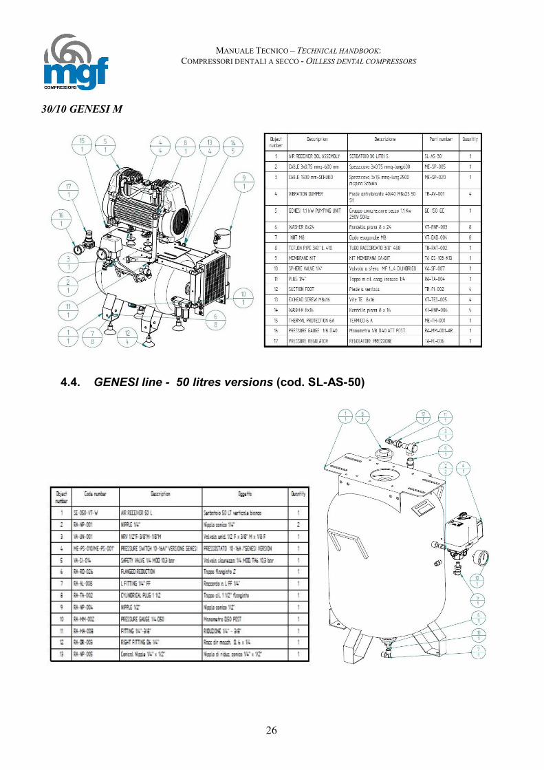
30/10 GENESI M
4.4. GENESI line - 50 litres versions (cod. SL-AS-50)

MANUALE TECNICO – TECHNICAL HANDBOOK: COMPRESSORI DENTALI A SECCO - OILLESS DENTAL COMPRESSORS
27
50/10 GENESI S
50/10 GENESI M

MANUALE TECNICO – TECHNICAL HANDBOOK: COMPRESSORI DENTALI A SECCO - OILLESS DENTAL COMPRESSORS
28
4.5. PRIME 1 line - 30 litres versions (cod. SL-AS-30)
30/7 PRIME S

MANUALE TECNICO – TECHNICAL HANDBOOK: COMPRESSORI DENTALI A SECCO - OILLESS DENTAL COMPRESSORS
29
4.6. Kit essiccazione PRIME 1 – PRIME 1 dryer kit TA-ES-103-K1
30/7 PRIME M

MANUALE TECNICO – TECHNICAL HANDBOOK: COMPRESSORI DENTALI A SECCO - OILLESS DENTAL COMPRESSORS
30
4.7. PRIME 2 line - 30 litres versions (cod. SL-AS-30-1)
30/15 PRIME S

MANUALE TECNICO – TECHNICAL HANDBOOK: COMPRESSORI DENTALI A SECCO - OILLESS DENTAL COMPRESSORS
31
4.8. Kit essiccazione PRIME 2-3 – PRIME 2-3 dryer kit TA-ES-101-K1
30/15 PRIME M

MANUALE TECNICO – TECHNICAL HANDBOOK: COMPRESSORI DENTALI A SECCO - OILLESS DENTAL COMPRESSORS
32
4.9. PRIME 2-3 line - 50 litres versions (cod. SL-AS-50)
50/15 PRIME S

MANUALE TECNICO – TECHNICAL HANDBOOK: COMPRESSORI DENTALI A SECCO - OILLESS DENTAL COMPRESSORS
33
50/25 PRIME S
KIT ESSICCAZIONE/DRYER KIT TA-ES-101-K1

MANUALE TECNICO – TECHNICAL HANDBOOK: COMPRESSORI DENTALI A SECCO - OILLESS DENTAL COMPRESSORS
34
50/15 PRIME M
50/25 PRIME M

MANUALE TECNICO – TECHNICAL HANDBOOK: COMPRESSORI DENTALI A SECCO - OILLESS DENTAL COMPRESSORS
35
4.10. PRIME line - 100 litres versions 100/30 TANDEM PRIME S
100/50 TANDEM PRIME S

MANUALE TECNICO – TECHNICAL HANDBOOK: COMPRESSORI DENTALI A SECCO - OILLESS DENTAL COMPRESSORS
36
Versioni con centralina temporizzata, codice centralina Versions with delayed timer, electronic board code: Mod. 100/30 TANDEM PRIME S:ME-QC-010 Mod. 100/50 TANDEM PRIME S: ME-QC-010
4.11. Kit essiccazione PRIME TANDEM – PRIME TANDEM dryer kit TA-ES-102-K1
KIT raffreddamento e filtrazione – cooling and filtration kit TA-ES-100-K2

MANUALE TECNICO – TECHNICAL HANDBOOK: COMPRESSORI DENTALI A SECCO - OILLESS DENTAL COMPRESSORS
37
100/30 TANDEM PRIME M
100/50 TANDEM PRIME M TRIPHASE 10/50 TANDEM PRIME M (WITHOUT CODE ME-QC-013)
Versioni con centralina temporizzata, codice centralina Versions with delayed timer, electronic board code: Mod. 100/30 TANDEM PRIME M:ME-QC-010 Mod. 100/50 TANDEM PRIME M: ME-QC-010

MANUALE TECNICO – TECHNICAL HANDBOOK: COMPRESSORI DENTALI A SECCO - OILLESS DENTAL COMPRESSORS
38
200/75 TANDEM PRIME S

MANUALE TECNICO – TECHNICAL HANDBOOK: COMPRESSORI DENTALI A SECCO - OILLESS DENTAL COMPRESSORS
39
200/75 TANDEM PRIME M

MANUALE TECNICO – TECHNICAL HANDBOOK: COMPRESSORI DENTALI A SECCO - OILLESS DENTAL COMPRESSORS
40
KIT ESSICCAZIONE/DRYER KIT TA-ES-101-K1
KIT ESSICCAZIONE/DRYER KIT TA-ES-102-K1

MANUALE TECNICO – TECHNICAL HANDBOOK: COMPRESSORI DENTALI A SECCO - OILLESS DENTAL COMPRESSORS
41
4.12. Esploso dell’assemblato CS e SKY– CS and SKY Assembly drawing

MANUALE TECNICO – TECHNICAL HANDBOOK: COMPRESSORI DENTALI A SECCO - OILLESS DENTAL COMPRESSORS
42
Come utilizzare l’elenco ricambi:
1. Consultare l’esploso per individuare il componente necessario 2. Il numero in figura indica la posizione (N°.), riportata nella prima colonna della tabella. 3. La colonna quantità indica quanti pezzi del relativo codice sono utilizzati per compressore. 4. Le righe evidenziate in giallo rappresentano i ricambi raccomandati
N° CODICE DESCRIZIONE VERSIONE Q.TA’
39 CA-PA-082-C Pannello lato ispezione completo per CS 30 S e M CS tutte le versioni 1 CA-PA-089-C Pannello lato ispezione completo per CS TANDEM CS TANDEM 1 CA-PA-074-C Pannello lato ispezione completo per CS 50 S e M CS tutte le versioni 1
40 CA-PA-080-C Pannello base completo per CS 30 S e M CS tutte le versioni 1 CA-PA-031-C Pannello base completo per CS TANDEM CS TANDEM 1 CA-PA-070-C Pannello base completo per CS 50 S e M CS tutte le versioni 1
41 CA-PA-081-C Pannello frontale completo per CS 30 S e M CS tutte le versioni 1 CA-PA-088-C Pannello frontale completo per CS TANDEM CS TANDEM 1 CA-PA-071-C Pannello frontale completo per CS 50 S e M CS tutte le versioni 1
42 CA-PA-086-1-C Pannello posteriore completo per CS 30 S e M CS tutte le versioni 1 CA-PA-092-C Pannello posteriore completo per CS TANDEM CS TANDEM 1 CA-PA-072-C Pannello posteriore completo per CS 50 S e M CS tutte le versioni 1
43 CA-PA-086-C Pannello laterale completo per CS 30 S e M CS tutte le versioni 1 CA-PA-091-C Pannello laterale completo per CS TANDEM CS TANDEM 1 CA-PA-077-C Pannello laterale completo per CS 50 S e M CS tutte le versioni 1
44 CA-PA-083-C Pannello superiore completo per CS 30 S M CS tutte le versioni 1 CA-PA-034-C Pannello superiore completo per CS TANDEM CS TANDEM 1 CA-PA-075-C Pannello superiore completo per CS 50 S M CS tutte le versioni 1
45 TA-VR-001 Ventola assiale mod. 4E230B CS M tutte le versioni, SKY
30/5, 30/7, 30/10, 30/15 1-2
TA-VR-002 Ventolino assiale 5E230B CS M versioni 30/15 30/25;SKY 50/20, 100/40 1-2
46 RA-MM-006 Manometro attacco posteriore con staffa CS tutte le versioni 1 47 ME-DS-025 Iinterruttore luminoso bipolare 16A CS tutte le versioni 1-2 48 RA-VS-001 Valvola a sfera MF 1/4 CS tutte le versioni 2 49 RA-DR-001 Racc. diritto masch. cil. D. 8 x 1/4" CS versioni M 1
51 TR-RT-005 Ruote diam. 50 girevole, vite M8x20 CS 30 tutte le versioni 4 TR-RT-003 Ruote diam. 60 girevole, vite M12x20 CS 50 e 100 tutte le versioni 4
52 ST-GU-001-SKY Cappottina superiore SKY tutte le versioni 1-2 53 ST-GU-002-SKY Cappottina inferiore SKY tutte le versioni 1-2
54
ME-TH-001 Termico 6 A SKY 30/5 1 ME-TH-005 Termico 8 A SKY 30/7, 30/10 1 ME-TH-002 Termico 10 A SKY 30/15, 50/15, 100/30 1-2 ME-TH-003 Termico 13 A SKY 50/20, 100/40 1-2
55 ME-TM-007 Sensore di temperatura CS, SKY tutte le versioni 1 56 ME-TM-008 Cavo sensore di temperatura CS, SKY tutte le versioni 1

MANUALE TECNICO – TECHNICAL HANDBOOK: COMPRESSORI DENTALI A SECCO - OILLESS DENTAL COMPRESSORS
43
How to read the spare part list:
1. Check the drawing to find required component 2. The number in the drawing indicates the position (N°) and it is mentioned in the first
column of the list below. 3. Q.ty column indicates the number of components required for one compressor. 4. Yellow lines are recommended spare parts
POS CODICE DESCRIPTION VERSION Q.TY
39 CA-PA-082-C Complete inspection panel CS 30 S and M CS 30 all versions 1 CA-PA-089-C Complete inspection panel CS TANDEM CS TANDEM 1 CA-PA-074-C Complete inspection panel CS 50 S e M CS 50 all versions 1
40 CA-PA-080-C Complete basement for CS 30 S and M CS 30 all versions 1 CA-PA-031-C Complete basement for CS TANDEM CS TANDEM 1 CA-PA-070-C Complete basement for CS 50 S and M CS 50 all versions 1
41 CA-PA-081-C Complete frontal panel for CS 30 S and M CS 30 all versions 1 CA-PA-088-C Complete frontal panel for CS TANDEM CS TANDEM 1 CA-PA-071-C Complete frontal panel for CS 50 S and M CS 50 all versions 1
42 CA-PA-086-1-C Complete rear panel for CS CS 30 S and M CS 30 all versions 1 CA-PA-087-C Complete rear panel for CS TANDEM CS TANDEM 1 CA-PA-092-C Complete rear panel for CS 50 S and M CS 50 all versions 1
43 CA-PA-086-C Complete lateral panel for CS 30 S and M CS 30 all versions 1 CA-PA-091-C Complete lateral panel for CS TANDEM CS TANDEM 1 CA-PA-077-C Complete lateral panel for CS 50 S and M CS 50 all versions 1
44 CA-PA-083-C Complete upper panel for CS 30 and M CS 30 all versions 1 CA-PA-034-C Complete upper panel for CS TANDEM CS TANDEM 1 CA-PA-075-C Complete upper panel for CS 50 S and M CS 50 all versions 1
45 TA-VR-001 Fan mod. 4E230B CS SCE all version, SKY 30/5,
30/7, 30/10, 30/15 1-2
TA-VR-002 Fan mod. 5E230B SKY 50/20, 100/40 1-2 46 RA-MM-006 Pressure gauge CS all versions 1 47 ME-DS-025 Luminous breaker 16A CS all versions 1-2 48 RA-VS-001 Ball valve MF 1/4 CS all versions 2 49 RA-DR-001 Pipe fitting d 8 X ¼” CS all M versions 1
51 TR-RT-005 Wheel diam. 50, M8x20 CS 30 all versions 4 TR-RT-003 Wheel diam. 60, M12x20 CS 50 and 100 alll versions 4
52 ST-GU-001-SKY Cover top SKY all versions 1-2 53 ST-GU-002-SKY Cover bottom SKY all versions 1-2
54
ME-TH-001 Thermic 6 A SKY 30/5 1 ME-TH-005 Thermic 8 A SKY 30/7, 30/10 1 ME-TH-002 Thermic 10 A SKY 30/15, 50/15, 100/30 1-2 ME-TH-003 Thermic 13 A SKY 50/20, 100/40 1-2
55 ME-TM-007 Temperature sensor CS, SKY all versions 1 56 ME-TM-008 Temperature sensor cable CS, SKY all versions 1

MANUALE TECNICO – TECHNICAL HANDBOOK: COMPRESSORI DENTALI A SECCO - OILLESS DENTAL COMPRESSORS
44
4.13. Elenco ricambi linea TOP AIR – TOP AIR line spare parts list Come utilizzare l’elenco ricambi:
1. Consultare l’esploso per individuare il componente necessario 2. Il numero in figura indica la posizione (POS.), riportata nella prima colonna della tabella. 3. La colonna quantità indica quanti pezzi del relativo codice sono utilizzati per compressore. 4. Le righe evidenziate in giallo rappresentano i ricambi raccomandati
How to read the spare part list:
1. Check the drawing to find required component 2. The number in the drawing indicates the position (POS.) and it is mentioned in the first column
of the list below. 3. Q.ty column indicates the number of components required for one compressor. 4. Yellow lines are recommended spare parts
Codice/Code Descrizione Description Modello/model
SE-006-SM-G Serbatoio 6 Lt x JOJO senza manico grigio Grey air tank 6 Lt. No handle SILENT TOP AIR 6/1B
SE-024-SM-W Serbatoio 24 Lt. senza manico bianco White air tank 24 Lt. With handle 24/1B SE-050-CA-W Serbatoio 50 LT. carrellato bar 11 bianco White air tank 50 Lt. With wheels 50/2B CAR
ME-PS-001 Presso stato completo di flangia a 4 vie Pressure switch complete with flange 4 ways ALL THE MODELS
VA-SI-002 Valvola di sicurezza 1/4" 8 bar certificate CE PED Safety valve 1/4" 8 bar CE PED certified ALL THE MODELS
VA-UN-009 Valvola di non ritorno 3/8M x 1/4F x 1/8F Non return valve 3/8M x 1/4F x 1/8F ALL THE MODELS
GC-090-OF2 Gruppo compressore secco 0,65 kW - 2.800 rpm Compressor 0,65 kW - 2.800 rpm SILENT TOP AIR
6/1B
GC-090-OF Gruppo compressore secco 0,65 kW - 1.400 rpm Compressor 0,65 kW - 1.400 rpm ALL THE MODELS
TU-RAT-005 Tubo TA diam.6 L. 220 - racc. MF 1/8 x 1/4 High temperature pipe diam.6 L. 220 - MF 1/8 x 1/4 ALL THE MODELS
VA-EL-001 Elettrovalvola a due vie da 1/8" Solenoid valve 1/8" ALL THE MODELS
TA-FL-009 Regolatore di pressione G 1/4" Pressure regulator G 1/4" SILENT TOP AIR 6/1B
TA-FL-001 Filtro riduttore 1/4" gas tazza trasparente Filter/Pressure reducer 1/4" 24/1B, 50/2B CAR RA-MM-001 Manometro 1/8" D.40 attacco posteriore Pressure gauge 1/8" D.40 back fitted 24/1B, 50/2B CAR RA-MM-002 Manometro 1/4" D.50 attacco posteriore Pressure gauge 1/4" D.50 back fitted 24/1B, 50/2B CAR
RA-MM-009 Manometro attac.post.1/8 c/staffa D.40 12 bar cassa acciaio Pressure gauge back fitted 1/8 D.40 SILENT TOP AIR
6/1B
TA-VR-001 Ventola elettrica assiale mod. 4E230BT Cooling fan mod. 4E230BT SILENT TOP AIR 6/1B
TA-VR-001-A Griglia in metallo per ventola 4E230BT Cooling fan protection mod. 4E230BT SILENT TOP AIR 6/1B
TR-MA-001 Maniglia Baby A / HELPADENT Baby A / HELPADENT Handle SILENT TOP AIR 6/1B
TR-FM-001 Fermaporte cilind. 30x30 nero Rubber feet 30x30 black SILENT TOP AIR 6/1B
VA-SF-007 Valvola a sfera MF 1/4 CILINDRICO Ball valve MF ¼” SILENT TOP AIR 6/1B
RA-SC-001 Scarico condensa 3/8" Drain cock MF 3/8 cylindric 50/2B CAR
RA-SC-002 Scarico condensa 1/4" Drain cock MF 1/4 cylindric SILENT TOP AIR 6/1B, 24/1B
MANUALE TECNICO – TECHNICAL HANDBOOK: COMPRESSORI DENTALI A SECCO - OILLESS DENTAL COMPRESSORS
45
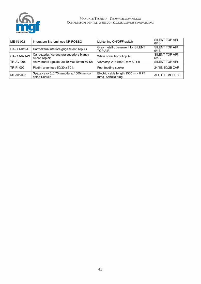
ME-IN-002 Interuttore Bip luminoso NR ROSSO Lightening ON/OFF switch SILENT TOP AIR 6/1B
CA-CR-019-G Carrozzeria inferiore griga Silent Top Air Grey metallic basement for SILENT TOP AIR
SILENT TOP AIR 6/1B
CA-CR-021-W Carrozzeria / carenatura superiore bianca Silent Top air White cover body Top Air SILENT TOP AIR
6/1B TR-AV-005 Antivibrante sgolato 20x19 M8x10mm 50 Sh Vibrostop 20X19X10 mm 50 Sh SILENT TOP AIR
TR-PI-002 Piedini a ventosa 50/30 x 50 lt Feet feeding sucker 24/1B, 50/2B CAR
ME-SP-003 Spezz.cavo 3x0,75 mmq-lung.1500 mm con spina Schuko
Electric cable length 1500 m. - 0.75 mmq Schuko plug ALL THE MODELS

MANUALE TECNICO – TECHNICAL HANDBOOK: COMPRESSORI DENTALI A SECCO - OILLESS DENTAL COMPRESSORS
46
5 Grafici di portata – Air flow datasheet 5.1 Versioni 0,75 KW, 1,5 KW e 2,2 KW PRIME – Versioni 0,45 Kw e 0,65 KW
Top AIR - Versions 0,75 KW, 1,5 KW e 2,2 KW PRIME – Versions 0,45 Kw and 0,65 KW Top AIR
Test conditions:
Air temperature: 20°C External air pressure: 1013 mbar RPM: 1480 rpm Air spec. Vol. at the indicated T and p: 0,830 m3/Kg
ARIA RESA - DELIVERY AIR - PRIME LINE
04080
120160200240280320360
0
2 2
9
4 5
8
6 8
6
8 1
14
10
145
Pressione ( bar - PSI )
Lt/m
in
Versione 1,0 Hp - 0,75kWVersione 2,0 Hp - 1,5 kW
Versione 3,0 Hp - 2,2 kW
ARIA RESA - DELIVERY AIR - TOP AIR LINE
04080
120160200240280320
0
1 1
4,5
2 2
9
3 4
4
4 5
8
5 7
2
6 8
6
7 1
00
8 1
14
Pressione ( bar - PSI )
Lt/m
in
Versione 0,9 Hp - 0,62kW 1.400 rpmVersione 0,9 Hp - 0,62kW 2.800 rpmVersione 0,6 Hp - 0,45kW 2.800 rpm

MANUALE TECNICO – TECHNICAL HANDBOOK: COMPRESSORI DENTALI A SECCO - OILLESS DENTAL COMPRESSORS
47
5.2 Versioni 0,55 kW e 1,1 kW NUOVO GENESI – 0,55 kW and 1,1 kW New Genesi versions
Test conditions: Air temperature: 20°C External air pressure: 1013 mbar RPM: 1480 rpm Air spec. Vol. at the indicated T and p: 0,830 m3/Kg
0
40
80
120
160
200
Lt/m
in
1 2 3 4 5 6 7 8 9 10Bar
ARIA RESA - AIR DELIVERY- GENESI LINE
Versione 1,5 HP - 1,1 kW
Versione 0,75 HP - 0,55 kW

MANUALE TECNICO – TECHNICAL HANDBOOK: COMPRESSORI DENTALI A SECCO - OILLESS DENTAL COMPRESSORS
48
6 Manutenzione compressori a secco – Oilless compressors
maintenance (PRIME and GENESI versions)
Il presente paragrafo descrive le operazioni di manutenzione cui deve essere sottoposto il compressore per un suo corretto ed efficiente funzionamento. L’ordine secondo cui sono elencate le operazioni di manutenzione è in base alla frequenza con cui le operazioni stesse devono essere eseguite. Si elencano in primo luogo le operazioni di manutenzione ordinaria, quindi direttamente eseguibili dall’utente finale, successivamente si elencheranno le operazioni di manutenzione straordinaria, per le quali MGF raccomanda l’intervento di tecnici specializzati. This paragraph describes maintenance operations required by MGF oilless compressors to guarantee its correct and efficient working. The following maintenance operations are listed according to frequency that each operation requires. Firstly are described ordinary maintenance operations, that are usually made directly by end users, then follow extra-ordinary maintenance operations that have to be made by specialized technicians only.
6.1 Operazioni di manutenzione ordinaria – Ordinary maintenance operations
a) Scarico della condensa (solo versioni senza essiccatore) – periodicità:
settimanale – Water relief (versions without dryer only) – periodicity: weekly Lo scarico della condensa è collocato nella parte inferiore del serbatoio (pos. 27 esploso pag. 24 del Technical Handbook– versioni non silenziate e SKY), o nella parte inferiore del pannello frontale per le versioni CS. Spegnere il compressore e svitare lo scarico/aprire rubinetto, lasciare aperto fino al completo svuotamento del serbatoio. Richiudere lo scarico/rubinetto. Opzionalmente è disponibile anche uno scarico automatico della condensa. Water relief is placed under the tank (pos. 27 on the drawing at page 24 from MGF Technical Handbook – for not silenced and Sky versions), or in the lower side of the front panel for CS versions. Switch off the compressor and unscrew the water relief/ open the drain cock, let it opened till the complete tank discharging. Close the water relief, drain cock. On demand is also available an automatic drain cock. b) Scarico tazza filtro FR (solo versioni senza essiccatore, non silenziate e SKY) –
periodicità: bisettimanale FR filter relief (only SKY, not silenced and without dryer versions) – periodicity: every 2 weeks.
Il filtro riduttore è collocato all’uscita dell’aria (pos. 19 esploso pag.24), scaricarlo bi-settimanalmente pigiando l’innesto collocato nella parte inferiore della tazza.

MANUALE TECNICO – TECHNICAL HANDBOOK: COMPRESSORI DENTALI A SECCO - OILLESS DENTAL COMPRESSORS
49
FR filter reducer is placed after the pressure switch at the air exit (pos. 19 – drawing page 24), discharge it every 2 weeks pushing the small button placed at the bottom of the glass cup. c) Pulizia filtri di aspirazione (tutte le versioni) – periodicità: semestrale
Aspiration filters cleaning (all the versions) – periodicity: every 6 months Il filtro di aspirazione è collocato sul copriventola (pos. 30 esploso di pag.24), rimuovere la cartuccia verificandone lo stato: pulirla con un getto d’aria, in caso di usura estrema sostituirla. Al termine riposizionare il filtro. Aspiration filter is placed on the cooling fan casing (pos. 30 – drawing at page 24), remove the cartridge and check its condition: clean the cartridge with a compressed air flow, in case replace it. Put the cartridge in its original position. d) Sostituzione delle cartucce dei filtri (pre-filtrazione essiccatoi a membrana e
filtrazione di linea) – periodicità: annuale Pre-filters for membrane dryers and line filters cartridges replacement – periodicity: yearly.
I prefiltri del sistema di essiccazione e la cartuccia del filtro di linea (quando presenti) devono essere sostituiti annualmente. Seguire le seguenti istruzioni:
I. Scollegare il compressore dall’alimentazione elettrica II. Aprire il rubinetto di linea o lo scarico di condensa fino ad eliminare la pressione residua
all’interno del serbatoio III. Svitare la tazza del filtro manualmente IV. Smontare la cartuccia e sostituirla con la cartuccia nuova. V. Rimontare la tazza del filtro
ATTENZIONE!
Riposizionare l’o-ring alla base della tazza del filtro in maniera corretta, sostituire l’o-ring se necessario.

MANUALE TECNICO – TECHNICAL HANDBOOK: COMPRESSORI DENTALI A SECCO - OILLESS DENTAL COMPRESSORS
50
Dryer pre-filtration and and line filters cartridges (if present) must be replaced every year. Follow the present instructions:
I. Disconnect the compressor from the main supply II. Open the air drain cock or the condensate relief from the air receiver and relief residual
pressure contained in the air receiver III. Manually unscrew the filter receiver IV. Unscrew the cartridge as shown in the picture above and replace it with the new cartridge V. Fix again the filter receiver
WARNING!
Carefully place the o-ring on the lip of the filter receiver, replace the o-ring if necessary.
6.2 Operazioni di manutenzione straordinaria – Extra-ordinary maintenance operations
COMPRESSORI PRIME – PRIME COMPRESSORS: a) Controllo/sostituzione degli anelli elastici e dei segmenti – periodicità: ogni
3.000 ore - Elastic rings, adjustable rings checking/Replacement – periodicity: every 3.000 ore
Anelli elastici e segmenti sono gli unici componenti del compressore soggetti ad usura, per le applicazioni nel mercato dentale il periodo di vita è quantificato in 2/3 anni corrispondenti in condizioni di utilizzo standard del compressore a circa 3.000 ore. Per un intervento in sicurezza si consiglia la sostituzione ogni 2 anni. Per verificarne lo stato è necessario rimuovere la testa del cilindro, la piastra valvole e il cilindro; anelli e segmenti sono collocati sul pistone (consultare gli esplosi PRIME da pagina 6 a pagina 13 del presente manuale). Verificarne lo stato di usura, che se eccessivo rischia di compromettere l’integrità del pistone stesso e della piastra valvole, sostituirli se necessario. Dopo la sostituzione e il riassemblaggio della testa, eseguire un collaudo di 1 ora lasciando funzionare il compressore scollegando il tubo di mandata del compressore, in maniera tale da rodare i nuovi componenti a pressione atmosferica. Elastic rings and adjustable rings are the only components subject to wear, for dental applications periodicity is esteemed in 2,5 – 3 years, that corresponds to 3.000 working hours in standard condition use. Anyway for a safe maintenance we recommend the replacement every 2 years. To check their condition is necessary to open the cylinder cap, the valve block and the cylinder( check drawings from page 6 to page 13 of the present manual)). Check their wear condition and replace them if necessary, please note that excessive wear may cause damages to the piston and the valve block. After the substitution reassemble the compressor head and make a 1 hour testing: disconnect the delivery pipe and let the compressor run at atmospherically pressure to run in the new components.

MANUALE TECNICO – TECHNICAL HANDBOOK: COMPRESSORI DENTALI A SECCO - OILLESS DENTAL COMPRESSORS
51
Seguono i dettagli relativi agli spessori minimi dei segmenti e degli anelli elastici necessari a garantire la portata dei compressori: Here below measures details for elastic rings and adjustable rings minimum thickness: Codice - code Descrizione Description Spessore min. -
Min. thickness MA-MG00001 SEGMENTO
COMPRESSIONE PISTON RING 3,5 mm
MA-MG00002 FASCIA GUIDA PISTONE
PISTON ADJUSTABLE RING 1,5 mm
COMPRESSORI GENESI – GENESI COMPRESSORS: b) Controllo/sostituzione dei segmenti – periodicità: ogni 1.500 ore - Elastic rings checking/Replacement – periodicity: every 1.500 ore I segmenti sono gli unici componenti del compressore soggetti ad usura, per le applicazioni nel mercato dentale il periodo di vita è quantificato in 2 anni corrispondenti in condizioni di utilizzo standard del compressore a circa 1.500 ore. Per un intervento in sicurezza si consiglia la sostituzione ogni 2 anni. Per verificarne lo stato è necessario rimuovere la testa del cilindro, la piastra valvole e il cilindro; i segmenti sono collocati tra la biella e il piattello dell’imbiellaggio (consultare l’esploso GENESI a pagina 20 pos. 23 del presente manuale). Verificarne lo stato di usura, che se eccessivo rischia di compromettere l’integrità del pistone stesso e della piastra valvole, sostituirli se necessario. Dopo la sostituzione e il ri-assemblaggio della testa, eseguire un collaudo di 1 ora lasciando funzionare il compressore scollegando il tubo di mandata del compressore, in maniera tale da rodare i nuovi componenti a pressione atmosferica.
ATTENZIONE Per rimontare la vite di biella M6x30 (pos. 43 nell’esploso a pag. 20) dopo la sostituzione del
segmento, utilizzare Loctite 242 per garantire la tenuta della vite all’interno della biella. Elastic rings are the only components subject to wear, for dental applications periodicity is esteemed in 2 years, that corresponds to 1.500 working hours in standard condition use. Anyway for a safe maintenance we recommend the replacement every 2 years. To check their condition is necessary to open the cylinder cap, the valve plate and the cylinder ( check the drawing at page 20 – pos. 23 of the present manual)). Check their wear condition and replace them if necessary, unscrewing the screw in position 43 and the disk in position 24 of the drawing at page 20, you can now remove and replace the elastic ring. After the substitution reassemble the compressor head and make a 1 hour testing: disconnect the delivery pipe and let the compressor run at atmospherically pressure to run in the new components. Please note that excessive wear may cause damages to the piston and the valve block.
ATTENTION
To properly fit the screw M6x30 (pos. 43 in the drawing at page 20) after ring replacement, always use Loctite 242 to warrantee the correct mechanical seal between the screw and the
connecting rod

MANUALE TECNICO – TECHNICAL HANDBOOK: COMPRESSORI DENTALI A SECCO - OILLESS DENTAL COMPRESSORS
52
c) Pulizia delle valvole e della piastra valvolare -– periodicità: ogni 3.000 ore –
Valves and valve plate clearing – periodicity: every 3.000 hours Le valvole e le piastre valvolari sono soggette a deterioramento dovuto all’accumulo di impurità provenienti dall’aspirazione e dal consumo dei materiali di cui al punto a). Per una perfetta efficienza del compressore ogni 3.000 ore controllare valvole e piastra valvolare. In caso di sporcizia rimovibile pulire i componenti con del diluente e riassemblarli, in caso di sporcizia persistente o danni ai componenti sostituire il tutto. L’operazione di smontaggio/rimontaggio è la medesima come sopra. Valves and valve plates are subjected to dirt residuals coming from aspiration and from the consumable components describe at the above point a). Control valves and valve plates every 3.000 hours for a perfect compressor efficiency. In case of removable dirt residuals clean valves and valve plate with a diluents and assemble them again, in case of hard dirtiness or damages replace the components. Instruction for the operation are the same as at the above point a). d) Sostituzione allumina per l’essiccatore ( solo essiccatori ad adsorbimento) –
periodicità (only adsorption air dryers): ogni 3 anni – allumina replacement for dryer – periodicity: every 3 years
L’allumina è il materiale essiccante contenuto nelle colonne dell’essiccatore, dopo 3 anni di funzionamento l’efficienza del materiale diminuisce e di conseguenza peggiora il funzionamento dell’essiccatore. Per garantire una perfetta efficienza negli anni è necessario sostituire l’allumina. L’operazione deve essere fatta con cautela per evitare di disperdere le centinaia di “palline” di allumina contenute nella colonna al momento dell’apertura: I. Smontare l’essiccatore dal compressore svitandolo dalla staffa di supporto e dal tubo di
mandata e aspirazione. II. Svitare il dado superiore che fissa il serpentino di raffreddamento collocato intorno alla
colonna alla piastra superiore. III. Svitare il dado posto sotto la piastra inferiore e che fissa il tirante collocato tra le due colonne IV. Prima di procedere con la rimozione della staffa superiore accertarsi che le due colonne di
alluminio siano ben salde alla base inferiore, in quanto se in fase di rimozione della base superiore si sollevassero anche le colonne si provocherebbe la fuori uscita dell’allumina
V. Rimossa la base superiore svuotare le colonne rovesciando l’allumina contenuta in un recipiente.
VI. Riempire le colonne con l’allumina nuova e rimontare l’essiccatore Allumina is the drying material inside the dryer columns, after 3 years allumina efficiency decreases and as a consequence dryer running becomes worst. To guarantee a perfect dryer running is necessary to replace allumina. Operation has to be made paying the maximum attention to avoid allumina leak during dryer opening: I. Disassemble the dryer from the compressor removing it from the support hanger and from
the delivery and aspiration pipe. II. Unscrew the nut placed under the upper aluminium block that fixes the cooling coil placed
around the dryer column to the same aluminium block

MANUALE TECNICO – TECHNICAL HANDBOOK: COMPRESSORI DENTALI A SECCO - OILLESS DENTAL COMPRESSORS
53
III. Unscrew the nut placed under the lower aluminium block that fixes the tension rod between the two columns
IV. Before proceeding with the upper aluminium block removal, be sure that the two columns are fixed to the lower aluminium block, because if during this operation columns are lifted, allumina will be lost.
V. After the upper aluminium block removal, empty the columns from allumina. VI. Fill the two columns with new allumina and assemble the set.
6.3 Kit ricambi per manutenzione compressori MGF – Spare parts kit for MGF compressors maintenance
Sono disponibili i kit di ricambi per eseguire le operazioni di manutenzione sui compressori a secco MGF ordinando semplicemente un codice all’interno del quale sono contenuti tutti i ricambi necessari alla manutenzione del compressore stesso. I kit di seguito elencati sono ricambi raccomandati MGF spare parts kit for maintenance are available, with a single code it is possible to order the kit of spare part necessary to provide compressor maintenance. Following kits are recommended spare parts.
CODICE DESCRIZIONE VERSIONE PERIODICITA’ PR-GC-010-K Kit ricambi versioni PRIME 0,75 kW Tutti i modelli PRIME da 0,75 kW 2 ANNI / 3.000 ore PR-GC-011-K Kit ricambi versioni PRIME 1,5 kW Tutti i modelli PRIME da 1,5 kW 2 ANNI / 3.000 ore PR-GC-014-K Kit ricambi versioni PRIME 2,2 kW Tutti i modelli PRIME da 2,2 kW 2 ANNI / 3.000 ore PR-GC-030-K PR-GC-010-K + piastra valvola completa * Tutti i modelli PRIME da 0,75 kW 2 ANNI / 3.000 ore PR-GC-031-K PR-GC-011-K+ piastra valvola completa * Tutti i modelli PRIME da 1,5 kW 2 ANNI / 3.000 ore PR-GC-032-K PR-GC-014-K+ piastra valvola completa * Tutti i modelli PRIME da 2,2 kW 2 ANNI / 3.000 ore MG-GC-010-K Kit ricambi versioni nuovo GENESI 0,55 kW Tutti i modelli NUOVO GENESI da 0,55 kW 1 ANNO/1.500 ore MG-GC-011-K Kit ricambi versioni nuovo GENESI 1,1 kW Tutti i modelli NUOVO GENESI da 1,1 kW 1 ANNO/1.500 ore MA-MG02002-C Piastra valvolare completa Tutti i modelli PRIME e NUOVO GENESI 2 ANNI/3.000 ore HB-GC-010-K Kit ricambi versioni TOP AIR 0,65 kW Tutti i modelli TOP AIR da 0,65 kW 1 ANNO/1.500 ore HB-GC-011-K Kit ricambi versioni TOP AIR 0,45 kW Tutti i modelli TOP AIR da 0,45 kW 1 ANNO/1.500 ore TA-AL-001 Kit ricambi essiccatori (allumina+ cartuccia) Versioni SCE 3 ANNI / 3.500 ore TA-FL-001-K Kit cartucce versioni S Versioni S 1 ANNO TA-FL-024-K Kit cartucce pre-filtri essiccatore membrana Versioni M fino a PRIME 0,75 kW 1 ANNO TA-FL-026-K Kit cartucce pre-filtri essiccatore membrana Versioni M da PRIME 1,5 kW 1 ANNO
CODE DESCRIPTION VERSION PERIODICITY PR-GC-010-K Spare part kit for PRIME 0,75 kW versions PRIME 0,75 kW 2 years / 3.000 h PR-GC-011-K Spare part kit for PRIME 1,5 kW versions PRIME 1,5 kW 2 years / 3.000 h PR-GC-014-K Spare part kit for PRIME 2,2 kW versions PRIME 2,2 kW 2 years / 3.000 h PR-GC-030-K PR-GC-010-K + valve plate complete * PRIME 0,75 kW 2 years / 3.000 h PR-GC-031-K PR-GC-011-K+ valve plate complete * PRIME 1,5 kW 2 years / 3.000 h PR-GC-032-K PR-GC-014-K+ valve plate complete * PRIME 2,2 kW 2 years / 3.000 h

MANUALE TECNICO – TECHNICAL HANDBOOK: COMPRESSORI DENTALI A SECCO - OILLESS DENTAL COMPRESSORS
54
MG-GC-010-K Spare part kit for GENESI 0,55 kW versions NEW GENESI 0,55 kW 1 year /1.500 h MG-GC-011-K Spare part kit for GENESI 1,1 kW versions NEW GENESI 1,1 kW 1 year /1.500 h MA-MG02002-C Complete valve plate PRIME and NEW GENESI 2 years/3.000 h HB-GC-010-K Spare part kit for TOP AIR 0,65 kW versions TOP AIR 0,65 kW 1 year /1.500 h HB-GC-011-K Spare part kit for TOP AIR 0,45 kW versions TOP AIR 0,45 kW 1 year /1.500 h TA-AL-001 Spare part kit for Air Dryer SCE VERSIONS 3 years / 3.500 h TA-FL-001-K Cartridges filters kit for S versions S versions 1 year TA-FL-024-K Cartridge filters kit for membrane dryer M versions till PRIME 0,75 kW 1 year TA-FL-026-K Cartridge filters kit for membrane dryer M versions from PRIME 1,5 kW 1 year
Il kit ricambi per versioni PRIME , NUOVO GENESI, TOP AIR e produzione antecedente include: Spare parts kit for PRIME, NEW GENESI, TOP AIR and previous production includes:
a) Filtri di aspirazione - Air aspiration filters b) Segmenti elastici - Elastic rings c) Anelli guida (solo PRIME) - Adjustable rings (PRIME only) d) O-rings e) Cartuccia filtro di linea (no kit TOP AIR) - Delivery air filter cartridge (no TOP AIR kit)
Il kit ricambi essiccatori comprende l’allumina e la cartuccia filtro del pre-filtro.
Air dryer spare part kit includes allumina and pre-filter cartridge.
Il kit ricambi PRIME , NUOVO GENESI, TOP AIR contrassegnato con asterisco comprende, oltre a quanto sopra elencato, anche la piastra valvolare complete Spare parts kit for PRIME, NEW GENESI, TOP AIR market with asterisk includes the above mentioned parts and the complete valve plate.
Condizioni operative di riferimento – Average operating conditions Gli intervalli di manutenzione sopra indicati sono rilevati alle seguenti condizioni medie: Maintenance intervals above indicated are valid at the following average operating conditions:
- Temperatura ambiente / Ambient temperature: 20°C - Ciclo di funzionamento / duty cycle: 50% - Umidità relative /Relative Humidity: 50%
Condizioni di funzionamento più gravose possono richiedere intervalli di manutenzione più ravvicinati, si consiglia in questi casi un controllo annuale del compressore. More stressful operating conditions can determinate closer maintenance intervals, in these cases annual compressor control is recommended.

MANUALE TECNICO – TECHNICAL HANDBOOK: COMPRESSORI DENTALI A SECCO - OILLESS DENTAL COMPRESSORS
55
6.4 Regolazione del pressostato – Pressure switch calibration
LINE MOTOR
LINE MOTOR
A A
B-
+
+ +- -
Normalmente la taratura delle pressioni minime e massime è già eseguite dalla fabbrica (p fissato a 2 bar); nel caso si voglia effettuare una regolazione eseguire le operazioni indicate di seguito: Vite A: Regolazione della pressione minima (cut-in) – entrambe le viti devono essere regolate al medesimo livello. Notare che per regolare la pressione massima è sufficiente regolare le viti A (pressione di minima), perché il differenziale di pressione (p) è fissato. Vite B: Regolazione del differenziale min-max pressione – attualmente regolato a 2 bar. La pressione di avvio del compressore (minima pressione o cut in) è regolabile tramite le 2 viti indicate come Vite A. Girando in senso orario entrambe le viti si incrementerà il valore della pressione minima di avvio del compressore. Girando in senso antiorario essa diminuirà. La pressione di arresto (massima pressione o cut-out) si avrà regolando la vite di intervallo min-max pressione (pressione minima+intervallo=pressione massima). Girando in senso orario la vite B aumenterà l’intervallo tra pressione minima e pressione massima. Normalmente i compressori MGF Sil-Eol sono tarati su 6/8 Bar o 5/7 bar (versioni 0,75 e 2 HP). Usually minimum and maximum pressure are pre-set by the factory (p fixed at 2 bar); if problems develop with the cut-in and cut-out pressure read the following operations

MANUALE TECNICO – TECHNICAL HANDBOOK: COMPRESSORI DENTALI A SECCO - OILLESS DENTAL COMPRESSORS
56
Screws A: Minimum pressure adjustment (cut-in) – both of them has to be regulated at the same level. Note that to regulate Max pressure is enough to regulate screws A (min. pressure), because the differential pressure (p) is fixed. Screw B: Differential min-max pressure adjustment (cut-out) – actually regulated at 2 bar. The cut-in pressure is set by even adjustment of the two screws A. Turn clockwise to increase the switch-on and anticlockwise to reduce it. The cut-out pressure is set by means of differential screw B (cut-in pressure+differential=cut-out pressure). Turn clockwise to increase the differential. MGF compressors are set on 6/8 Bar approx. 80-108 psi or 5/7 bar (0,75 and 1 HP versions).
6.5 Condizioni operative dell’essiccatore a membrana – Membrane air dryer operating
Il sistema di essiccazione a membrana MGF è totalmente pneumatico, non necessita di nessun controllo elettrico, per cui è estremamente affidabile. Inoltre la membrana, se usata in maniera corretta, non necessita di manutenzione e garantisce elevate prestazioni per tutta la vita utile del compressore. The MGF membrane air dryer is fully pneumatic, it does not need any electronic connection, therefore reliability is extremely high. Besides the membrane, when properly used, does not need maintenance and warrantees high performance for all the life of the compressor
AFFIDABILITA E SEMPLICITA: Nessuna parte in movimento: no valvole di non ritorno, no valvole, no mateirali di consumo Nessun cmponente elettronico: no elettrovalvole, no schede elettroniche, no collegamenti
elettrici
MANUALE TECNICO – TECHNICAL HANDBOOK: COMPRESSORI DENTALI A SECCO - OILLESS DENTAL COMPRESSORS
57
PRESTAZIONI DURATURE: Non c’è usura del materiale dessicante, nessuna riduzione delle prestazioni!
ESSICCATTORE PRIVO DI MANUTENZIONE: La membrana non richiede manutenzione Solo il sistema di filtrazione a monte dell’essiccatore necessita della regolare
sostituzione degli elementi filtranti, che deve essere effettuata ogni anno ( controlla e richiedi il kit di elementi filtranti per il tuo compressore MGF controllando il codice nella tabella al punto 5.3 qua sopra)
RELIABILITY & SIMPLICITY: no moving parts: no solenoid valves, no valves, no wear at all! no electronic components: solenoid valves, electronic control board, electric connections
CONSISTENT PERFORMANCE: no desiccant degradation: compared to twin towers dryers, there is no permormance
reduction in the time!
MAINTENANCE FREE: No membrane maintenance required: compared to twin towers dryers where allumina
replacement is periodically required! only the prefiltration needs to be replaced on a regular basis (filter cartridges –
check the proper cartridge kit for your MGF compressor in the proper section 5.3 above)
6.6 Condizioni operative dell’essiccatore ad adsorbimento – Adsorption air dryer operating
Il primo passo per offrire un supporto tecnico agli essiccatori montati sui compressori MGF è quello di conoscere il suo sistema di funzionamento. Il sistema di essiccazione completo è composto da una serie di componenti, se accade un guasto la corretta procedura da seguire è quella di analizzare tutti i componenti che compongono il sistema di essiccazione. Vi preghiamo di consultare il disegno d’assieme a pagina 24 di questo manuale: i componenti inclusi nel riquadro “SCE VERSION” compongono il sistema di essiccazione.
1. Scambiatore di calore (Pos.5): posizionato prima dell’essiccatore equipaggiato con una ventola addizionale ad alta portata per le motorizzazioni da 2 HP e 3 HP. Lo scambiatore di calore è necessario per garantire la corretta temperatura dell’aria in ingresso all’essiccatore (la temperatura dell’aria in ingresso deve essere inferiore ai 45 °C). In caso di guasto all’essiccatore si prega di verificare il corretto funzionamento dello scambiatore: la ventola

MANUALE TECNICO – TECHNICAL HANDBOOK: COMPRESSORI DENTALI A SECCO - OILLESS DENTAL COMPRESSORS
58
di raffreddamento deve sempre funzionare quando il compressore è in funzione, la temperatura all’entrata dell’essiccatore sia sempre al di sotto dei 40°C (per verificare tale dato è sufficiente mettere un termometro a contatto sul raccordo n° 22 (pag.24).
2. Filtro pre-essiccazione (Pos.8): questo filtro, posizionato tra lo scambiatore e l’entrata nell’essiccatore, fa si che ci sia una prima fase di separazione della condensa. L’acqua è scaricata automaticamente: ogni volta che il compressore si ferma e la pressione lungo i componenti di mandata nel serbatoio (eccetto il serbatoio naturalmente) viene scaricata dall’elettrovalvola situata in posizione 23, questo filtro scarica automaticamente l’acqua presente nella sua tazza. Nel caso di mancato funzionamento dell’essiccatore si prega di verificare che tale filtro funzioni correttamente e che la condensa creata venga scaricata correttamente; la tazza trasparente mai deve essere piena d’acqua!
3. Elettrovalvola (Pos.23): controllare il corretto funzionamento, perché come precedentemente esposto, un mancato funzionamento dell’elettrovalvola non consente un corretto scarico d’acqua del filtro pre-essiccazione.
4. Essiccatore (Pos.10): l’essiccatore MGF è composto da 2 colonne. Queste due colonne lavorano in modo alternato e sono comandate da un timer posizionato all’interno della scatola di derivazione (pos. 36) sullo stesso essiccatore. Verificare la corretta temporizzazione (5 minuti a colonna) delle due colonne: le due elettrovalvole posizionate sotto le colonne. Quando una colonna lavora, l’elettrovalvola corrispondente non perde aria mentre perde una minima quantità d’aria la colonna che non lavora in quanto un flusso d’aria essiccato rigenera l’allumina presente nella colonna che non lavora. Nel caso in cui ci fosse un malfunzionamento verificare il corretto funzionamento dell’essiccatore e del timer verificando anche che vi sia presente la rumorosità del flusso d’aria all’interno della colonna.
NOTE: nel caso in cui il compressore fosse posizionato all’interno di una stanza con temperatura superiore ai 30°C e in caso di lungo funzionamento a regime del compressore stesso, l’aria in ingresso nel compressore ha una temperatura più elevata: lo scambiatore riduce comunque la temperatura al di sotto dei 45°C, ma si tenga presente che più bassa è la temperatura d’ingresso dello scambiatore migliore è l’essiccazione dell’aria che esce dall’essiccatore e quindi dal serbatoio. The first step to be able to provide a proper technical service on MGF compressor dryer system is to properly know its operating system. Complete drying system is composed by a set of components, if a failure happens the correct procedure to follow is to check the complete drying set. Please check the drawing at page 24 on MGF Technical Handbook: components from position number 3 up to position 11 build the dryer set.
1. Heat exchanger (pos. 5): placed before the dryer it is equipped with an additional cooling fan for the 2 HP and 3HP versions. Heat exchanger is necessary to guarantee the correct inlet air temperature to the dryer (inlet temperature has to be below 45°C). In case of dryer failure please check the proper heat exchanger working: cooling fan has to always run when the compressor is switched on, temperature at the dryer entrance always has to be below 40°C (to check it is enough to place a temperature feeler on the pipe placed in position 22 pag. 24.
2. Radiator Filter (pos.8): this filter, placed between the heat exchanger and the radiator, makes a first condensate separation. Water discharge is automatic: each time the compressor stops running and pressure along the components (except for the tank of course) is discharged by the solenoid valve placed in position 23, this filter automatically discharge residual water. In case of dryer failure please check that the Radiator filter properly discharge residual water in the glass, this glass never has to be full of water.

MANUALE TECNICO – TECHNICAL HANDBOOK: COMPRESSORI DENTALI A SECCO - OILLESS DENTAL COMPRESSORS
59
3. Solenoid valve (pos.23): check its proper working, because as above explained, solenoid valve failure does not allow the correct water discharge in the radiator filter.
4. Dryer (pos.10): MGF dryer is composed by 2 columns, these two columns work alternately and are ruled by a timer placed in the plastic box on the same dryer (pos. 3 on the picture at page 13 on the MGF instruction manual). Check the proper alternate running of the two columns: two solenoid valves are placed under the dryer (pos. 5 on the picture at page 13 on the MGF instruction manual), one column per time discharges air through the solenoid valve (it’s easy to feel it placing a finger on the solenoid valve exit). In case of dryer failure please check the correct working of the timer: if you can’t feel the air discharge from the solenoid valve and if you don’t hear the air flow noise when the timer reverses operating column, it means that timer has to replaced.
NOTE: in case of high room temperature (over 30°C) and in case of long time compressor running, air temperature inside the compressor becomes higher: heat exchanger always reduces it under 45°C, but when air temperature enter the dryer very close to the maximum allowed level (45°C), dryer efficiency is lower because when dried air reaches the tank it still has temperature around 30°C. Inside the tank this air temperature reduces and this may generate residual condensate.
6.7 Componentistica e kit di essiccazione - MGF air dryers components and available kits
Sono disponibili diversi kit di essiccazione per ogni compressore MGF, qua di seguito l’elenco dei kit in funzione del compressore MGF: MGF offer complete kits to replace or add dryers to your MGF compressor. Different kits are available according to the different MGF oilless compressor model: Code TA-ES-001-K1: Dryer kit complete for 30/7 version Code TA-ES-001-K2: Dryer kit complete for CS 30/7 version Code TA-ES-001-K3: Dryer kit complete for SKY 30/7 version Code TA-ES-002-K1: Dryer kit complete for 30/15 and 40/15 versions
1
2
3 4
7
6 5
9

MANUALE TECNICO – TECHNICAL HANDBOOK: COMPRESSORI DENTALI A SECCO - OILLESS DENTAL COMPRESSORS
60
Code TA-ES-002-K2: Dryer kit complete for 50/15 and 50/20 versions Code TA-ES-002-K3: Dryer kit complete for 100/30, 100/40 and SKY 100 versions Code TA-ES-002-K4: Dryer kit complete for CS 30/15 version Code TA-ES-002-K5: Dryer kit complete for SKY 30/15 AND SKY 40/15 versions Code TA-ES-002-K6: Dryer kit complete for SKY 50/15 and SKY 50/20 versions Code TA-ES-003-K1: Dryer kit complete or 30/5 and 30/10 GENESI versions
Il kit include:
1. Radiatore aria/aria 2. Tubo di collegamento tra radiatore e filtro 3. Prefiltro della condensa 4. Valvola solenoidale 5. Essiccatore 6. Quadro elettrico di controllo 7. Tubo di collegamento tra essiccatore e serbatoio 8. Raccorderia 9. Cablaggio elettrico
All the kits include:
1. Heat exchanger 2. Connection hose between the heat exchanger and the filter 3. Water filter 4. Solenoid valve 5. Dryer 6. Electronic control board 7. Connection hose from the dryer to the air receiver 8. Fittings 9. Electric cables
IMPORTANTE - IMPORTANT
Per tutte le installazioni dei kit di essiccazione è necessario il supporto di un tecnico. In caso di
necessità di aggiungere un kit di essiccazione sui compressori SKY, suggeriamo di inviare il compressore al fabbricante per fare eseguire l’operazione
If you need to add a dryer kit to your MGF compressor a technician support is required. In case of
SKY version MGF suggest to deliver the compressor back to the manufacturer to add drying system.

MANUALE TECNICO – TECHNICAL HANDBOOK: COMPRESSORI DENTALI A SECCO - OILLESS DENTAL COMPRESSORS
61
6.8 Settaggio dello scarico automatico di condensa – automatic drain setting
B
A D
C E Impostazione dei tempi per lo scarico della condensa – Drainage timing setting OFF (A) – Minimo 10 minuti - Minimum 10 minutes Per impostare la frequenza di scarico condensa (ogni quanto si vuole scaricare il serbatoio : impostabile da 5 a 40 minuti – per compressori a secco mai meno di 10 minuti). To set drain frequency (how often air receiver drainage is required : setting from 5 to 40 mins – for oilless compressors never less than 10 minutes). ON (B) – Massimo 5 secondi - Maximum 5 seconds Per impostare la durata dello scarico condensa dal serbatoio (impostabile sa 2 a 20 secondi – per compressori a secco mai più di 5 secondi). To set the lenght of the air receiver draining(setting from 2 to 20 seconds – for oilless compressors never more than 5 seconds). I tempi vanno impostati in modo da rimuovere completamente la condensa. I tempi corretti dipendono dal consumo effettivo dell’aria e dell’umidità ambientale. Autodrain setting must be done to remove all the water from the air receiver. Correct setting belongs to operating conditions and ambient humidity.

MANUALE TECNICO – TECHNICAL HANDBOOK: COMPRESSORI DENTALI A SECCO - OILLESS DENTAL COMPRESSORS
62
MANUTENZIONE – MAINTENANCE Pulire periodicamente il filtro all’interno del rubinetto come segue :
1. Chiudere completamente il rubinetto (C) per isolare l’aria compressa del serbatoio 2. Premere ripetutamente il pulsante TEST (D) per scaricare l’eventuale pressione residua 3. Svitare il tappo del rubinetto (E) 4. Togliere il filtro in maglia e pulirlo con aria compressa 5. Rimontare filtro e tappo (E) avvitandoli saldamente 6. Riaprire il rubinetto (C) lentamente verificando che non ci siano perdite 7. Premere il pulsante TEST (D) per verificare il corretto funzionamento del dispositivo
Periodically clean the internal filter as follows :
1. Close the drain cock ( C ) to avoid compressed air exit from the air receiver 2. Repeatedly push the TEST (D) button to discharge residual pressure 3. Unscrew the drain cock tap (E) 4. Remove the filter inside the body of the valve and clean it with compressed air 5. Place the filter in the original position, hardly screw again the tap ( E ) 6. Slowly open again the drain cock ( C) and check that there are no air leaks 7. Push the TEST (D) button to check the correct functioning of the device
For further information please contact the manufacturer at the address [email protected]


![· privind situatiile-financiare anuale individuale situatiile financiare anuale consolidate. C] Administratia a realizat inventarierea generala a patrimoniului, rezultatele acesteia](https://static.fdocuments.in/doc/165x107/5e44e7d83617da4b83221c69/privind-situatiile-financiare-anuale-individuale-situatiile-financiare-anuale-consolidate.jpg)