
LZ85202 IrDA Control Host Controller with USB Interface...
48
LZ85202 IrDA Control Host Controller with USB Interface User’s Guide Version 1.1 ®
Transcript of LZ85202 IrDA Control Host Controller with USB Interface...
LZ85202 IrDA Control Host Controller with USB InterfaceUser’s Guide
Version 1.1®
SHARP reserves the right to make changes in specifications described herein at any time and with-
out notice in order to improve design or reliability. SHARP does not assume any responsibility for
the use of any circuitry described; no circuit patent licenses are implied. SHARP assumes no
responsibility for damage caused by misuse or improper use of devices.
LIFE SUPPORT POLICYSHARP components should not be used in medical devices with life support functions, safety equip-ment (or similar applications where component failure would result in loss of life or physical harm),aerospace equipment, telecommunication equipment (trunk lines) or nuclear power control equip-ment. Contact a SHARP representative or sales office before using SHARP devices for any applica-tions other than those recommended by SHARP.
LIMITED WARRANTYSHARP warrants to its Customer that the Products will be free from defects in material and work-manship under normal use and service for a period of one year from the date of invoice. Customer’sexclusive remedy for breach of this warranty is that SHARP will either (i) repair or replace, at itsoption, any Product which fails during the warranty period because of such defect (if Customerpromptly reported the failure to SHARP in writing) or, (ii) if SHARP is unable to repair or replace,refund the purchase price of the Product upon its return to SHARP. This warranty does not apply toany Product which has been subjected to misuse, abnormal service or handling, or which has beenaltered or modified in design or construction, or which has been serviced or repaired by anyoneother than SHARP. The warranties set forth herein are in lieu of, and exclusive of, all other warran-ties, express or implied. ALL EXPRESS AND IMPLIED WARRANTIES, INCLUDING THE WAR-RANTIES OF MERCHANTABILITY, FITNESS FOR USE AND FITNESS FOR A PARTICULARPURPOSE, ARE SPECIFICALLY EXCLUDED. In no event will SHARP be liable, or in any wayresponsible, for any incidental or consequential economic or property damage.
The above warranty is also extended to Customers of SHARP authorized distributors with the fol-lowing exception: reports of failures of Products during the warranty period and return of Productsthat were purchased from an authorized distributor must be made through the distributor. In caseSHARP is unable to repair or replace such Products, refunds will be issued to the distributor in theamount of distributor cost.
LZ85202 IrDA Control Host Controller with USB Interface User’s Guide Version 1.1© 1999 Copyright SHARP Microelectronics of the Americas. Printed and Bound in USA.Reference No. SMA99091
IrDA Control Host Controller with USB Interface User’s Guide iii
Table of ContentsGeneral Description ...............................................................................................1
HC Features.......................................................................................................1
IrDA Control System..............................................................................................2
General Description ...........................................................................................2
IrDA Control Peripherals.................................................................................4
Protocol Stacks ..................................................................................................6
Enumeration Sequence..................................................................................6
Binding Sequence ..........................................................................................7
IrDA Control Host Controller Interface ...................................................................8
Interface with USB Transceiver LSI ...................................................................8
Interface with Serial EEPROM...........................................................................9
Interface with Infrared Transceiver (Front-end, FE) .........................................10
USB Dongle Functions Utilizing HC.....................................................................11
Module Structure..............................................................................................11
USB Protocol Process (USB Module) ..............................................................12
Endpoint .......................................................................................................12
Suspend Mode and Remote Wake-up .........................................................12
Dongle Driver................................................................................................13
Protocols Between Host and USB Dongle ...................................................14
USB Requests ..............................................................................................15
Descriptor .....................................................................................................16
IrDA Control Protocol Process (IrDA Control Module) .....................................19
Memorizing Enumeration Information...........................................................20
Support for the Peripherals...........................................................................21
DC BIAS Mode .............................................................................................21
Setting the Host Address (Using DIP Switch)...............................................22
USB-IrDA Control Bridge Process (USB-IrDA Bridge Module) ........................23
USB-IrDA Control Mapping ..........................................................................23
Status Indication LEDs .................................................................................23
Peripheral Power Supply Information ...........................................................24
Auto Repeat Cancellation for Keyboard Error ..............................................24
LZ85202
iv IrDA Control Host Controller with USB Interface User’s Guide
USB Dongle Operation.....................................................................................26
The Communication Between USB Dongle and Host (Windows 98) ...........26
USB-Enumeration on the USB Dongle.........................................................27
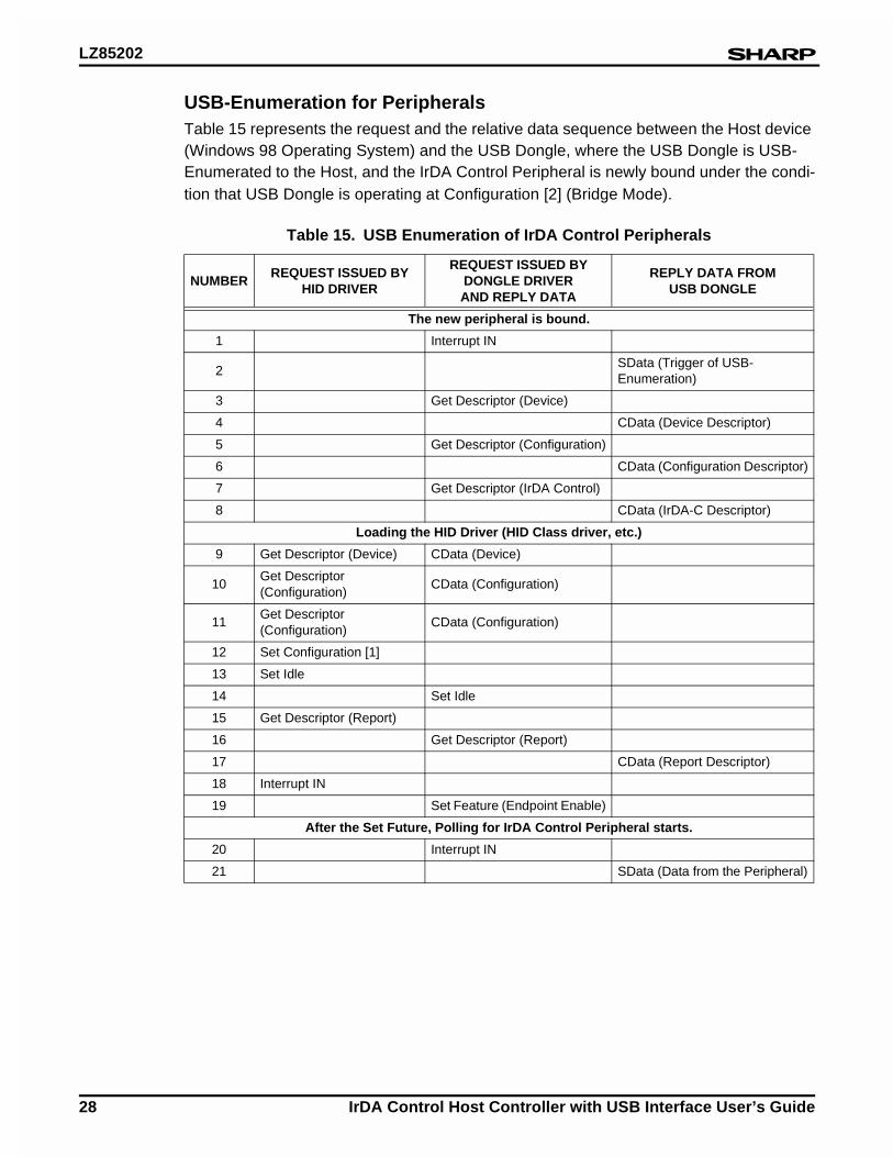
USB-Enumeration for Peripherals ................................................................28
Dongle Driver Request .................................................................................29
HID Driver Request ......................................................................................29
Pinouts.................................................................................................................30
Pinout Functions and Descriptions...................................................................31
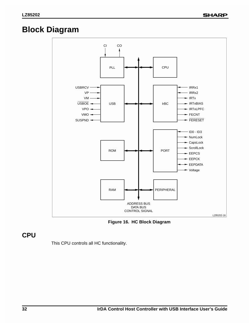
Block Diagram .....................................................................................................32
CPU..................................................................................................................32
PLL (Phase Lock Loop) and CG (Clock Generator).........................................33
USB (Universal Serial Bus) ..............................................................................33
IrBC..................................................................................................................34
RAM (Random Access Memory) and ROM (Read Only Memory)...................34
Port...................................................................................................................34
Serial EEPROM............................................................................................34
Status Indicator LED.....................................................................................34
DIP Switch....................................................................................................35
Reference Documents .........................................................................................35
Appendix..............................................................................................................36
IrDA Control Definitions....................................................................................38
Parts List ..........................................................................................................40
IrDA Control Host Controller with USB Interface User’s Guide v
List of FiguresHC Interface Signals..............................................................................................1
IrDA Control System..............................................................................................2
Required USB Dongle Functions for IrDA Control Subsystem..............................3
IrDA Control Host Dongle Implementation Example..............................................5
Enumeration Sequence .........................................................................................6
Binding Sequence..................................................................................................7
Interface Between HC and USB Transceiver LSI ..................................................8
Interface Between HC and Serial EEPROM..........................................................9
Interface Between HC and Infrared Transceiver .................................................10
Module Structure .................................................................................................11
Protocols Between Host and USB Dongle...........................................................14
Example of Using EP1 and EP3 Simultaneously (Keyboard with Pointing Device)..........................................................................20
Sequence of Auto Repeat Cancellation for Keyboard .........................................25
Requests and Data Stream Between Host and USB Dongle ..............................26
HC Pinout ............................................................................................................30
HC Block Diagram ...............................................................................................32
HC Recommended Oscillation Circuit .................................................................33
Serial EEPROM Bit Assignment ..........................................................................34
Status LED Bit Assignment..................................................................................34
DIP SW Assignment ............................................................................................35
Connection Between HC and FE without DC Bias ..............................................36
Connection Between HC and FE with DC Bias ...................................................37
USB Dongle Reference Circuit Schematic ..........................................................42
vi IrDA Control Host Controller with USB Interface User’s Guide
List of TablesEndpoint...............................................................................................................12
Emulation and Bridge Operation Modes..............................................................13
Standard Requests ..............................................................................................15
HID Class Request ..............................................................................................16
Device Descriptor ................................................................................................16
Configuration Descriptor ......................................................................................17
Interface Descriptor .............................................................................................17
HID Descriptor .....................................................................................................17
Endpoint Descriptor .............................................................................................18
Report Descriptor (Keyboard and Mouse Emulation Mode) ................................18
Bind Management................................................................................................19
Registration Numbering of Enumeration (Priority) ...............................................21
USB Request, IrDA Control Mapping ..................................................................23
USB Enumeration of USB Dongle .......................................................................27
USB Enumeration of IrDA Control Peripherals ....................................................28
LZ85202 Pinout Function.....................................................................................31
USB Maximum Packet Sizes ...............................................................................33
Parts List..............................................................................................................40
IrDA Control Host Controller with USB Interface User’s Guide 1
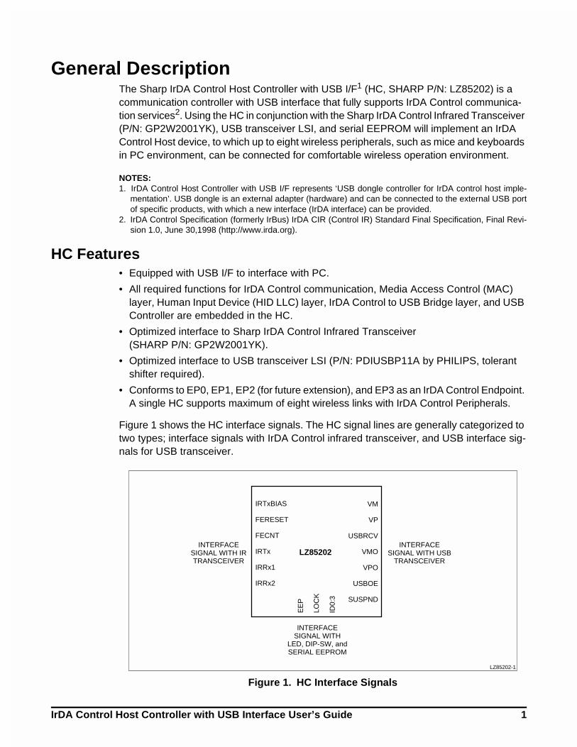
General DescriptionThe Sharp IrDA Control Host Controller with USB I/F1 (HC, SHARP P/N: LZ85202) is a communication controller with USB interface that fully supports IrDA Control communica-tion services2. Using the HC in conjunction with the Sharp IrDA Control Infrared Transceiver (P/N: GP2W2001YK), USB transceiver LSI, and serial EEPROM will implement an IrDA Control Host device, to which up to eight wireless peripherals, such as mice and keyboards in PC environment, can be connected for comfortable wireless operation environment.
NOTES:1. IrDA Control Host Controller with USB I/F represents ‘USB dongle controller for IrDA control host imple-
mentation’. USB dongle is an external adapter (hardware) and can be connected to the external USB portof specific products, with which a new interface (IrDA interface) can be provided.
2. IrDA Control Specification (formerly IrBus) IrDA CIR (Control IR) Standard Final Specification, Final Revi-sion 1.0, June 30,1998 (http://www.irda.org).
HC Features• Equipped with USB I/F to interface with PC.
• All required functions for IrDA Control communication, Media Access Control (MAC) layer, Human Input Device (HID LLC) layer, IrDA Control to USB Bridge layer, and USB Controller are embedded in the HC.
• Optimized interface to Sharp IrDA Control Infrared Transceiver (SHARP P/N: GP2W2001YK).
• Optimized interface to USB transceiver LSI (P/N: PDIUSBP11A by PHILIPS, tolerant shifter required).
• Conforms to EP0, EP1, EP2 (for future extension), and EP3 as an IrDA Control Endpoint. A single HC supports maximum of eight wireless links with IrDA Control Peripherals.
Figure 1 shows the HC interface signals. The HC signal lines are generally categorized to two types; interface signals with IrDA Control infrared transceiver, and USB interface sig-nals for USB transceiver.
Figure 1. HC Interface Signals
IRTxBIAS
FERESET
FECNT
IRTxINTERFACE
SIGNAL WITH IRTRANSCEIVER
INTERFACESIGNAL WITH
LED, DIP-SW, andSERIAL EEPROM
INTERFACESIGNAL WITH USB
TRANSCEIVERIRRx1
LZ85202
IRRx2
VM
VP
USBRCV
VMO
VPO
USBOE
SUSPND
EE
P
LOC
K
ID0:
3
LZ85202-1
LZ85202
2 IrDA Control Host Controller with USB Interface User’s Guide
IrDA Control SystemGeneral Description
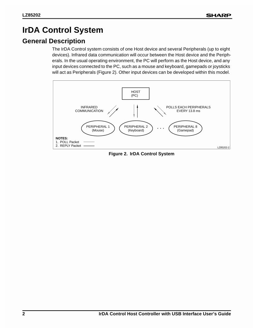
The IrDA Control system consists of one Host device and several Peripherals (up to eight devices). Infrared data communication will occur between the Host device and the Periph-erals. In the usual operating environment, the PC will perform as the Host device, and any input devices connected to the PC, such as a mouse and keyboard, gamepads or joysticks will act as Peripherals (Figure 2). Other input devices can be developed within this model.
Figure 2. IrDA Control System
HOST(PC)
. . .PERIPHERAL 1(Mouse)
INFRAREDCOMMUNICATION
POLLS EACH PERIPHERALSEVERY 13.8 ms
NOTES:1. POLL Packet2. REPLY Packet
PERIPHERAL 2(Keyboard)
PERIPHERAL 8(Gamepad)
LZ85202-2
LZ85202
IrDA Control Host Controller with USB Interface User’s Guide 3
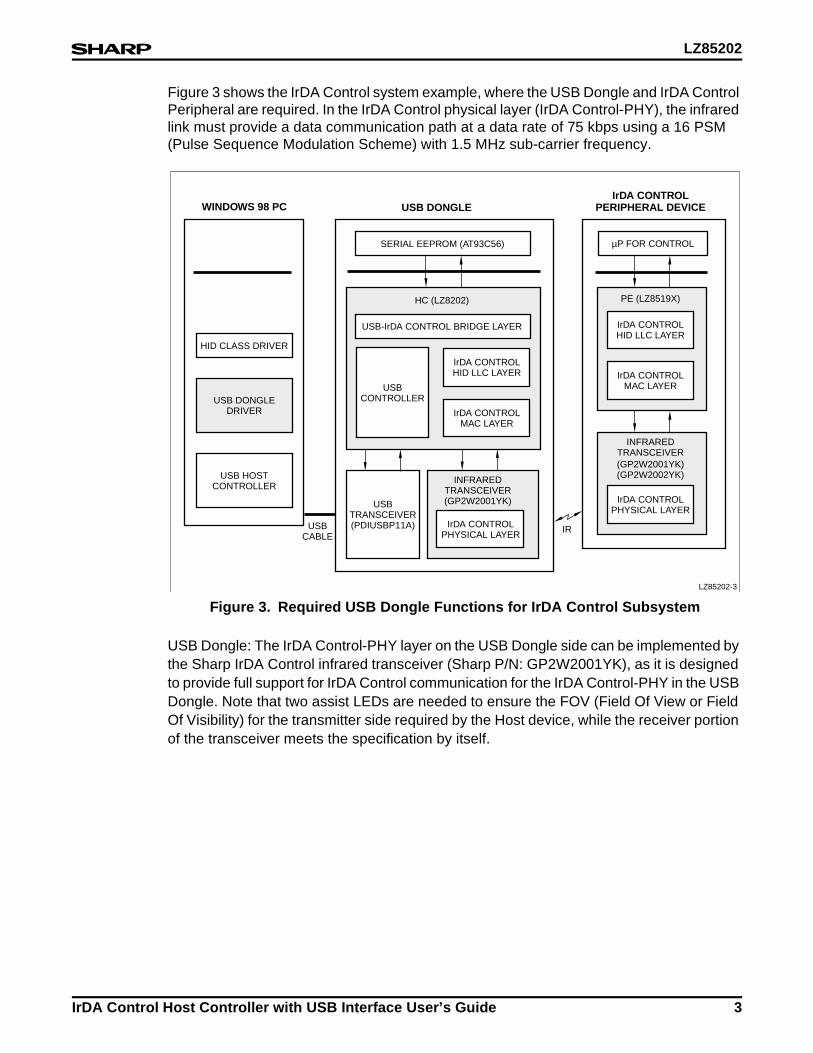
Figure 3 shows the IrDA Control system example, where the USB Dongle and IrDA Control Peripheral are required. In the IrDA Control physical layer (IrDA Control-PHY), the infrared link must provide a data communication path at a data rate of 75 kbps using a 16 PSM (Pulse Sequence Modulation Scheme) with 1.5 MHz sub-carrier frequency.
USB Dongle: The IrDA Control-PHY layer on the USB Dongle side can be implemented by the Sharp IrDA Control infrared transceiver (Sharp P/N: GP2W2001YK), as it is designed to provide full support for IrDA Control communication for the IrDA Control-PHY in the USB Dongle. Note that two assist LEDs are needed to ensure the FOV (Field Of View or Field Of Visibility) for the transmitter side required by the Host device, while the receiver portion of the transceiver meets the specification by itself.
Figure 3. Required USB Dongle Functions for IrDA Control Subsystem
HID CLASS DRIVER
WINDOWS 98 PC USB DONGLEIrDA CONTROL
PERIPHERAL DEVICE
SERIAL EEPROM (AT93C56) µP FOR CONTROL
USBTRANSCEIVER(PDIUSBP11A) IR
INFRAREDTRANSCEIVER(GP2W2001YK)
USB DONGLEDRIVER
USB HOSTCONTROLLER
USBCABLE
LZ85202-3
IrDA CONTROLPHYSICAL LAYER
IrDA CONTROLHID LLC LAYER
IrDA CONTROLMAC LAYER
USBCONTROLLER
USB-IrDA CONTROL BRIDGE LAYER
HC (LZ8202)
IrDA CONTROLHID LLC LAYER
PE (LZ8519X)
IrDA CONTROLMAC LAYER
INFRAREDTRANSCEIVER(GP2W2001YK)(GP2W2002YK)
IrDA CONTROLPHYSICAL LAYER
LZ85202
4 IrDA Control Host Controller with USB Interface User’s Guide
The IrDA Control MAC layer (IrDA Control-MAC) manages the IrDA Control infrared wire-less link between the Host device and the Peripherals. Actual activity of the MAC layer is shown below.
• The Host device will poll ‘Bound’ Peripherals in a certain order. The Host device will insert the communication data (the information forwarded from Host HID LLC Layer) into the polling packet for each Peripheral.
• The Host device will then wait for the corresponding response packets from the Peripherals. The received corresponding packets include the communication data from the Peripherals. The Host device will extract these data packets and forward them to its HID LLC layer.
• In the event that the corresponding packets from the Peripheral are missing for a certain time period, the Host device will stop polling them. This state will be seen when the user stops moving the Peripherals. This state is expressed as ‘The Peripheral is in an Unbound state’. On the other hand, while the Peripheral is polled, this state is expressed as ‘The Peripheral is in the Bound state’. The Host device will immediately re-start poll-ing the Peripheral when the Host device receives the IrDA Control infrared signal trans-mitted from the Unbound Peripherals. At this time it will again be bound. This step requires that the Peripheral was previously enumerated.
The HID LLC layer provides error correction, data re-sending, and flow management ser-vices between the USB Dongle and peripherals. The HID LLC layer formats information sent by the Peripherals to the Host device. The USB-IrDA Control bridge layer provides a data Communication Bridge between the USB data and the Peripheral data. It ensures inter-oper-ability between the USB data packets and the data packet sent by the IrDA Control periph-erals. The USB controller enables the USB interface for communication with the PC.
As described, five functions are PHY layer, MAC layer, HID LLC layer, USB-IrDA Control bridge layer, and USB controller, are required for the USB Dongle implementation.
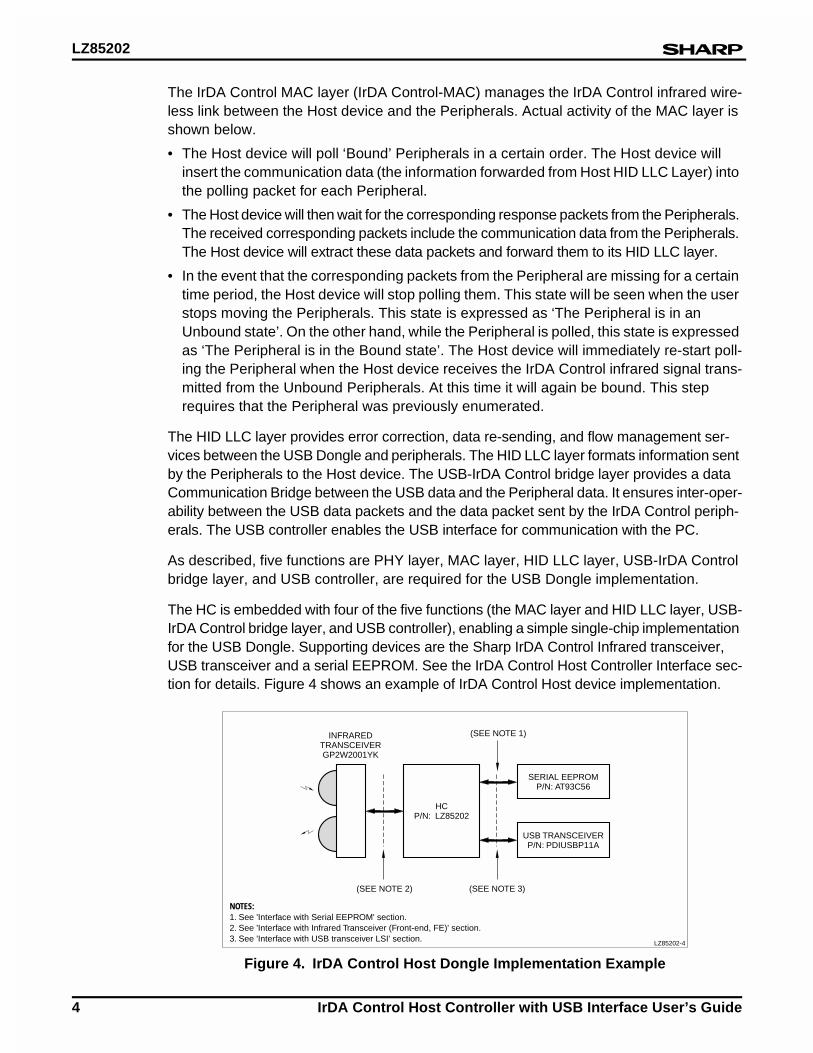
The HC is embedded with four of the five functions (the MAC layer and HID LLC layer, USB-IrDA Control bridge layer, and USB controller), enabling a simple single-chip implementation for the USB Dongle. Supporting devices are the Sharp IrDA Control Infrared transceiver, USB transceiver and a serial EEPROM. See the IrDA Control Host Controller Interface sec-tion for details. Figure 4 shows an example of IrDA Control Host device implementation.
Figure 4. IrDA Control Host Dongle Implementation Example
HCP/N: LZ85202
SERIAL EEPROMP/N: AT93C56
USB TRANSCEIVERP/N: PDIUSBP11A
(SEE NOTE 3)
(SEE NOTE 1)
(SEE NOTE 2)
NOTES:1. See 'Interface with Serial EEPROM' section.2. See 'Interface with Infrared Transceiver (Front-end, FE)' section.3. See 'Interface with USB transceiver LSI' section.
INFRAREDTRANSCEIVERGP2W2001YK
LZ85202-4
LZ85202
IrDA Control Host Controller with USB Interface User’s Guide 5
IrDA Control PeripheralsThe functions of the IrDA Control-PHY, MAC and LLC layers on the peripherals are similar to those of the USB Dongle. Infrared link communication with the USB Dongle can be made available by connecting infrared transceivers. GP2W2001YK, GP2W2002YK: either model will implement the peripherals depending on the peripheral type. The MAC layer functions on the peripherals are described below.
• The IrDA Control Peripheral would first send its identification data, such as PFID, Periph-eral Information etc., to a Host device to register itself. This registration process is called ‘Enumeration’.
• Once Enumeration is completed, the Host device will allocate the address (PADD) to the enumerated Peripherals and will start polling accordingly (the procedure to start polling is called ‘Binding’). The polling packet from the Host device to the Peripheral contains the data for the designated Peripheral. The IrDA Control MAC Layer in the Peripheral will extract this data and forward it to its upper layer, the HID LLC Layer. The Peripherals will reply with a response packet that includes the communication data from its HID LLC Layer. The Peripherals must start to respond within 213 µs from the receipt of the polling packet, if the Peripherals have any data for the Host device.
• The Peripheral Engine IC controls this response time.
The HID LLC layer provides error correction, data re-sending, and flow management services between the USB Dongle and the peripheral. IrDA Control Peripherals send information to the Host device by using the HID LLC layer. For the IrDA Control Peripheral implementation, Sharp provides an embedded communication controller called PE (Peripheral Engine, Sharp P/N: LZ85194). This communication LSI performs all functions of both MAC Layer and HID LLC Layer, and simplifies the peripheral implementation. With this LSI, the IrDA Control wireless peripherals can be implemented by just adding this PE, microcomputer for system control and the infrared transceiver.
In order to implement the whole IrDA Control system, HC (LZ85202), USB Transceiver (PDIUSBP11A), serial EEPROM (AT93C56)and infrared transceiver (GP2W2001YK, GP2W2002YK)are required for the USB Dongle. For the peripherals, PE (LZ85194), a Microcontroller for system control, infrared transceiver (GP2W2001YK, GP2W2002YK) are required.
LZ85202
6 IrDA Control Host Controller with USB Interface User’s Guide
Protocol StacksIn an IrDA Control subsystem, certain procedures are required to make the infrared wire-less communication available between a Host device and Peripherals. These required pro-cedures are described below.
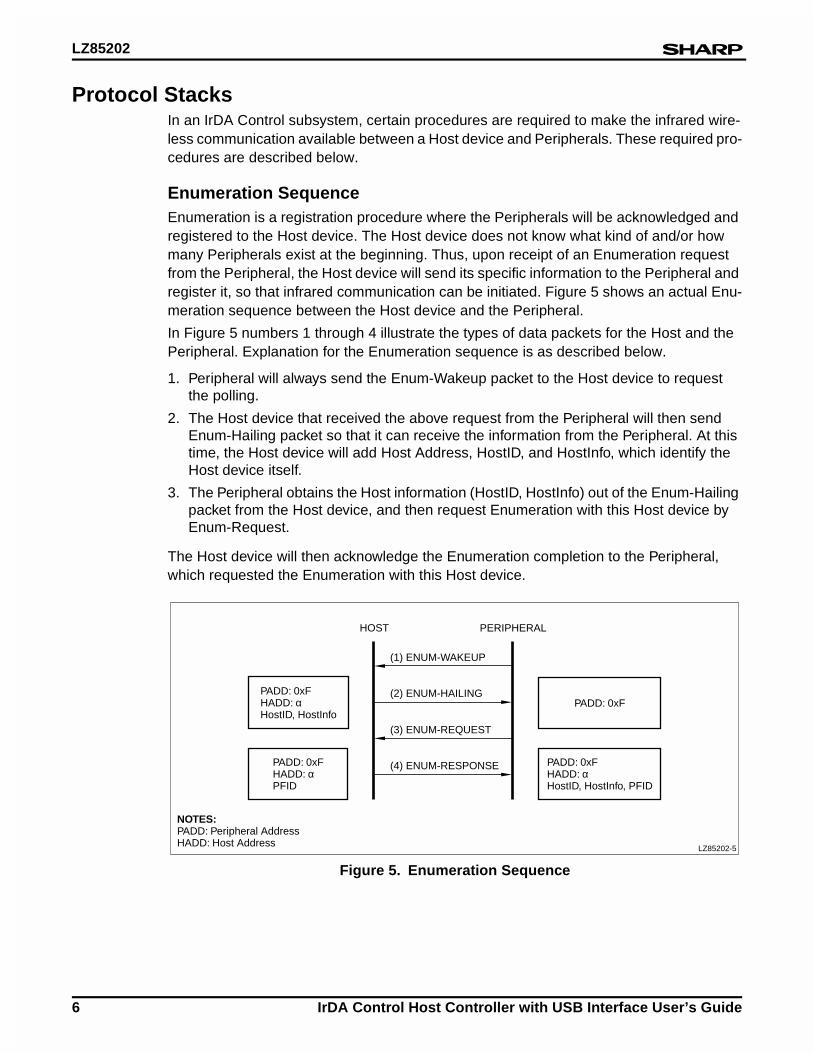
Enumeration SequenceEnumeration is a registration procedure where the Peripherals will be acknowledged and registered to the Host device. The Host device does not know what kind of and/or how many Peripherals exist at the beginning. Thus, upon receipt of an Enumeration request from the Peripheral, the Host device will send its specific information to the Peripheral and register it, so that infrared communication can be initiated. Figure 5 shows an actual Enu-meration sequence between the Host device and the Peripheral.
In Figure 5 numbers 1 through 4 illustrate the types of data packets for the Host and the Peripheral. Explanation for the Enumeration sequence is as described below.
1. Peripheral will always send the Enum-Wakeup packet to the Host device to request the polling.
2. The Host device that received the above request from the Peripheral will then send Enum-Hailing packet so that it can receive the information from the Peripheral. At this time, the Host device will add Host Address, HostID, and HostInfo, which identify the Host device itself.
3. The Peripheral obtains the Host information (HostID, HostInfo) out of the Enum-Hailing packet from the Host device, and then request Enumeration with this Host device by Enum-Request.
The Host device will then acknowledge the Enumeration completion to the Peripheral, which requested the Enumeration with this Host device.
Figure 5. Enumeration Sequence
PADD: 0xFHADD: αHostID, HostInfo
PADD: 0xFHADD: αPFID
NOTES:PADD: Peripheral AddressHADD: Host Address
PADD: 0xF
PADD: 0xFHADD: αHostID, HostInfo, PFID
LZ85202-5
(1) ENUM-WAKEUP
(2) ENUM-HAILING
(3) ENUM-REQUEST
(4) ENUM-RESPONSE
HOST PERIPHERAL
LZ85202
IrDA Control Host Controller with USB Interface User’s Guide 7
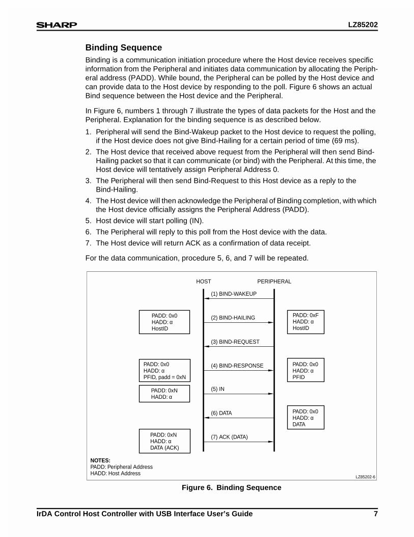
Binding SequenceBinding is a communication initiation procedure where the Host device receives specific information from the Peripheral and initiates data communication by allocating the Periph-eral address (PADD). While bound, the Peripheral can be polled by the Host device and can provide data to the Host device by responding to the poll. Figure 6 shows an actual Bind sequence between the Host device and the Peripheral.
In Figure 6, numbers 1 through 7 illustrate the types of data packets for the Host and the Peripheral. Explanation for the binding sequence is as described below.
1. Peripheral will send the Bind-Wakeup packet to the Host device to request the polling, if the Host device does not give Bind-Hailing for a certain period of time (69 ms).
2. The Host device that received above request from the Peripheral will then send Bind-Hailing packet so that it can communicate (or bind) with the Peripheral. At this time, the Host device will tentatively assign Peripheral Address 0.
3. The Peripheral will then send Bind-Request to this Host device as a reply to the Bind-Hailing.
4. The Host device will then acknowledge the Peripheral of Binding completion, with which the Host device officially assigns the Peripheral Address (PADD).
5. Host device will start polling (IN).
6. The Peripheral will reply to this poll from the Host device with the data.
7. The Host device will return ACK as a confirmation of data receipt.
For the data communication, procedure 5, 6, and 7 will be repeated.
Figure 6. Binding Sequence
PADD: 0x0HADD: αHostID
PADD: 0x0HADD: αPFID, padd = 0xN
NOTES:PADD: Peripheral AddressHADD: Host Address
PADD: 0xNHADD: αDATA (ACK)
PADD: 0xNHADD: α
PADD: 0xFHADD: αHostID
PADD: 0x0HADD: αPFID
PADD: 0x0HADD: αDATA
LZ85202-6
(1) BIND-WAKEUP
(2) BIND-HAILING
(3) BIND-REQUEST
(4) BIND-RESPONSE
HOST PERIPHERAL
(5) IN
(6) DATA
(7) ACK (DATA)
LZ85202
8 IrDA Control Host Controller with USB Interface User’s Guide
IrDA Control Host Controller InterfaceInterface with USB Transceiver LSI
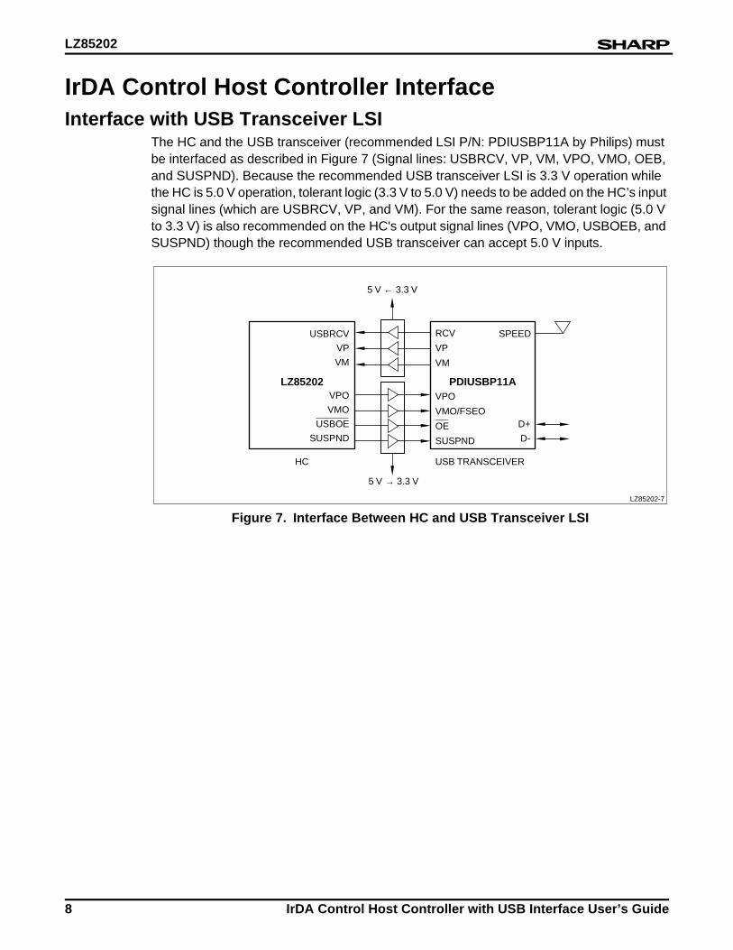
The HC and the USB transceiver (recommended LSI P/N: PDIUSBP11A by Philips) must be interfaced as described in Figure 7 (Signal lines: USBRCV, VP, VM, VPO, VMO, OEB, and SUSPND). Because the recommended USB transceiver LSI is 3.3 V operation while the HC is 5.0 V operation, tolerant logic (3.3 V to 5.0 V) needs to be added on the HC’s input signal lines (which are USBRCV, VP, and VM). For the same reason, tolerant logic (5.0 V to 3.3 V) is also recommended on the HC's output signal lines (VPO, VMO, USBOEB, and SUSPND) though the recommended USB transceiver can accept 5.0 V inputs.
Figure 7. Interface Between HC and USB Transceiver LSI
USBRCV
VP
VM
VPO
VMO
USBOE
SUSPND
RCV
VP
VM
VPO
VMO/FSEO
OE
SUSPND
LZ85202-7
LZ85202 PDIUSBP11A
5 V ← 3.3 V
SPEED
D+
D-
5 V → 3.3 V
USB TRANSCEIVERHC
LZ85202
IrDA Control Host Controller with USB Interface User’s Guide 9
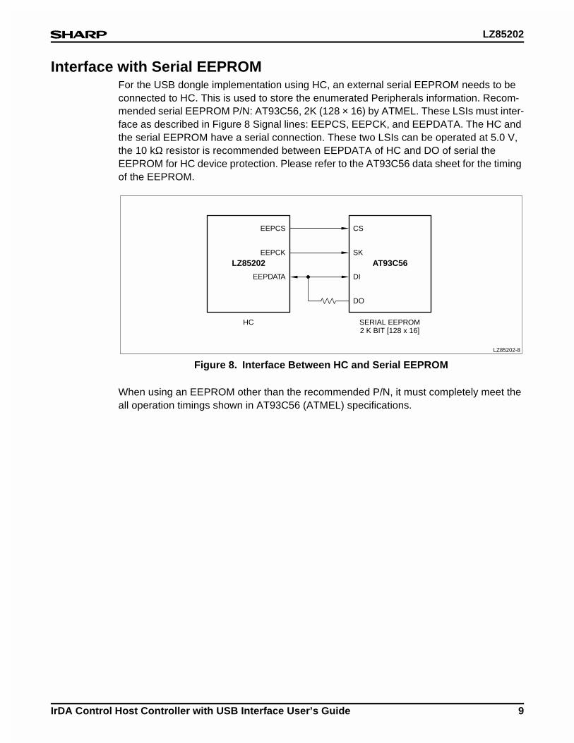
Interface with Serial EEPROMFor the USB dongle implementation using HC, an external serial EEPROM needs to be connected to HC. This is used to store the enumerated Peripherals information. Recom-mended serial EEPROM P/N: AT93C56, 2K (128 × 16) by ATMEL. These LSIs must inter-face as described in Figure 8 Signal lines: EEPCS, EEPCK, and EEPDATA. The HC and the serial EEPROM have a serial connection. These two LSIs can be operated at 5.0 V, the 10 kΩ resistor is recommended between EEPDATA of HC and DO of serial the EEPROM for HC device protection. Please refer to the AT93C56 data sheet for the timing of the EEPROM.
When using an EEPROM other than the recommended P/N, it must completely meet the all operation timings shown in AT93C56 (ATMEL) specifications.
Figure 8. Interface Between HC and Serial EEPROM
EEPCS
EEPCK
EEPDATA
CS
SK
DI
DO
LZ85202-8
LZ85202 AT93C56
SERIAL EEPROM2 K BIT [128 x 16]
HC
LZ85202
10 IrDA Control Host Controller with USB Interface User’s Guide
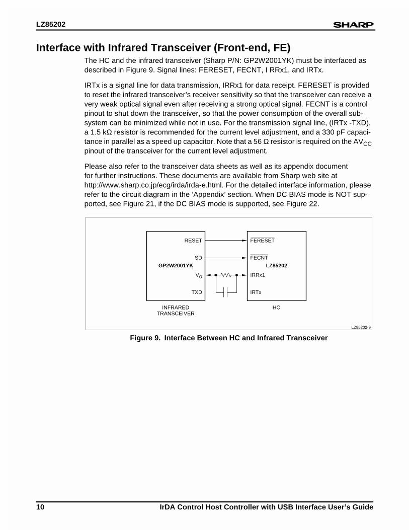
Interface with Infrared Transceiver (Front-end, FE)The HC and the infrared transceiver (Sharp P/N: GP2W2001YK) must be interfaced as described in Figure 9. Signal lines: FERESET, FECNT, I RRx1, and IRTx.
IRTx is a signal line for data transmission, IRRx1 for data receipt. FERESET is provided to reset the infrared transceiver’s receiver sensitivity so that the transceiver can receive a very weak optical signal even after receiving a strong optical signal. FECNT is a control pinout to shut down the transceiver, so that the power consumption of the overall sub-system can be minimized while not in use. For the transmission signal line, (IRTx -TXD), a 1.5 kΩ resistor is recommended for the current level adjustment, and a 330 pF capaci-tance in parallel as a speed up capacitor. Note that a 56 Ω resistor is required on the AVCC pinout of the transceiver for the current level adjustment.
Please also refer to the transceiver data sheets as well as its appendix document for further instructions. These documents are available from Sharp web site at http://www.sharp.co.jp/ecg/irda/irda-e.html. For the detailed interface information, please refer to the circuit diagram in the ‘Appendix’ section. When DC BIAS mode is NOT sup-ported, see Figure 21, if the DC BIAS mode is supported, see Figure 22.
Figure 9. Interface Between HC and Infrared Transceiver
RESET
SD
VO
TXD
FERESET
FECNT
IRRx1
IRTx
LZ85202-9
GP2W2001YK LZ85202
HCINFRAREDTRANSCEIVER
LZ85202
IrDA Control Host Controller with USB Interface User’s Guide 11
USB Dongle Functions Utilizing HCIn order for multiple peripherals (up to eight devices) to simultaneously communicate within the IrDA Control system, the USB Dongle (USB Function) is required in the system. This USB Dongle is the adapter connected to the USB I/F and it provides infrared commu-nication link with the task given below.
1. Connect the USB Dongle to the Host device via USB I/F.
2. Install the driver software (Dongle Driver software: see the ‘Dongle Driver’ section) into Windows98 OS
After task 2, driver software installed in Windows 98 OS (HID driver) can be made avail-able, by which the Host device can control maximum of eight peripherals over infrared communication. Other functions of the IrDA Control Host Dongle are listed below:
• With a combination of BIOS that supports USB keyboards in market place, the dongle will be recognized as a keyboard with pointing device capability, and then be recognized as USB dongle once all drivers are loaded to the Windows 98 Operating System (see the ‘Operation Mode (USB Configuration)’ section.
• Full Speed data transfer (12 Mbps) service is available as USB function.
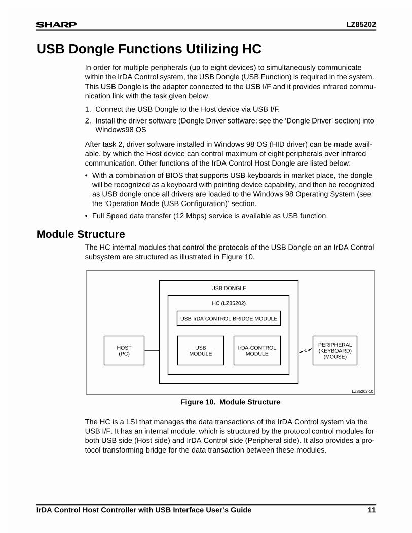
Module StructureThe HC internal modules that control the protocols of the USB Dongle on an IrDA Control subsystem are structured as illustrated in Figure 10.
The HC is a LSI that manages the data transactions of the IrDA Control system via the USB I/F. It has an internal module, which is structured by the protocol control modules for both USB side (Host side) and IrDA Control side (Peripheral side). It also provides a pro-tocol transforming bridge for the data transaction between these modules.
Figure 10. Module Structure
HOST(PC)
USBMODULE
USB-IrDA CONTROL BRIDGE MODULE
HC (LZ85202)
USB DONGLE
IrDA-CONTROLMODULE
PERIPHERAL(KEYBOARD)
(MOUSE)
LZ85202-10
LZ85202
12 IrDA Control Host Controller with USB Interface User’s Guide
USB Protocol Process (USB Module)In general, data exchanges between the Host device and the USB peripheral uses three different types of data, which are: TALKN packet (IN /OUT packet), data packet (packet of DATA0 and DATA1), and handshake packet (ACK, NAK and STALL).
In the IrDA Control data communication system, the HC’s internal USB module controls the protocols for the three different types of data packets, and takes the role of data trans-action bridge to the Dongle Driver (see the ‘Dongle Driver’ section).The following section describes the USB protocol process by the HC.
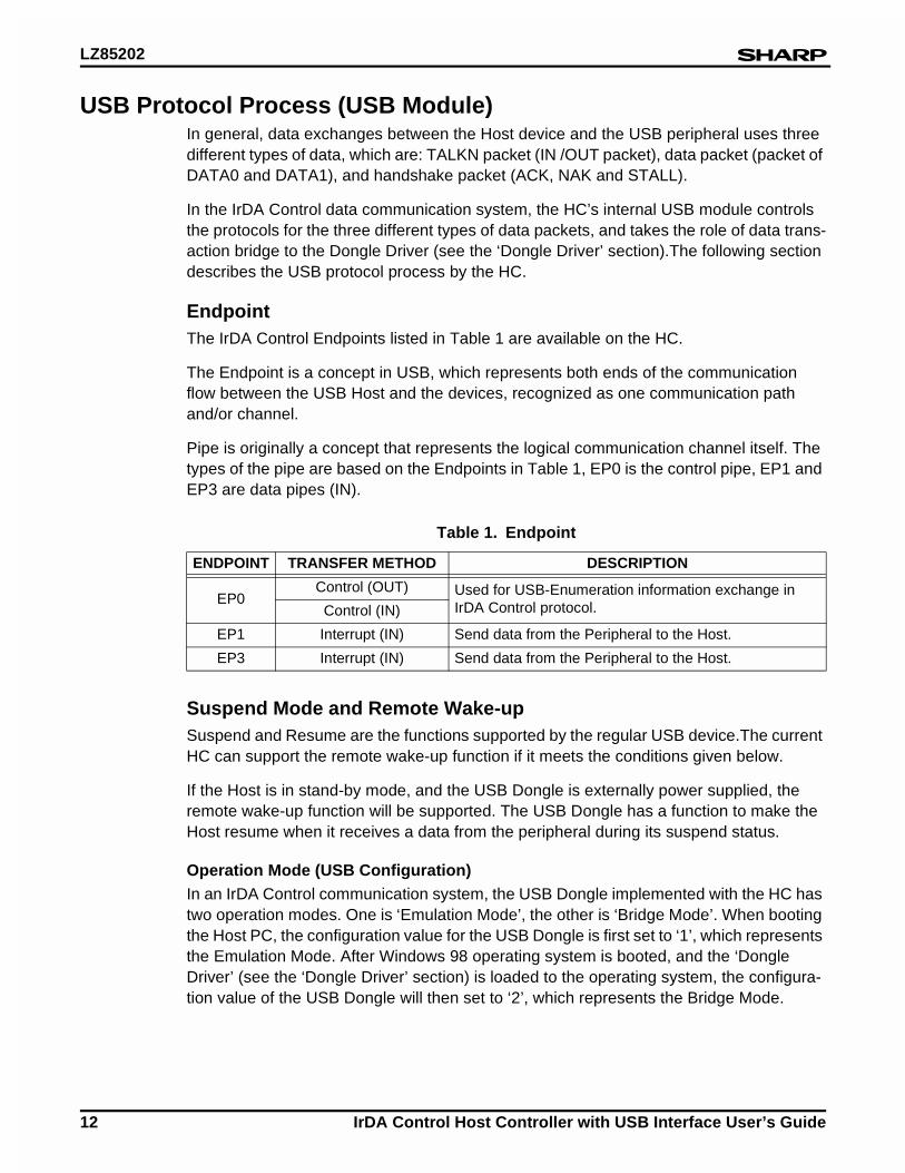
EndpointThe IrDA Control Endpoints listed in Table 1 are available on the HC.
The Endpoint is a concept in USB, which represents both ends of the communication flow between the USB Host and the devices, recognized as one communication path and/or channel.
Pipe is originally a concept that represents the logical communication channel itself. The types of the pipe are based on the Endpoints in Table 1, EP0 is the control pipe, EP1 and EP3 are data pipes (IN).
Suspend Mode and Remote Wake-upSuspend and Resume are the functions supported by the regular USB device.The current HC can support the remote wake-up function if it meets the conditions given below.
If the Host is in stand-by mode, and the USB Dongle is externally power supplied, the remote wake-up function will be supported. The USB Dongle has a function to make the Host resume when it receives a data from the peripheral during its suspend status.
Operation Mode (USB Configuration)In an IrDA Control communication system, the USB Dongle implemented with the HC has two operation modes. One is ‘Emulation Mode’, the other is ‘Bridge Mode’. When booting the Host PC, the configuration value for the USB Dongle is first set to ‘1’, which represents the Emulation Mode. After Windows 98 operating system is booted, and the ‘Dongle Driver’ (see the ‘Dongle Driver’ section) is loaded to the operating system, the configura-tion value of the USB Dongle will then set to ‘2’, which represents the Bridge Mode.
Table 1. Endpoint
ENDPOINT TRANSFER METHOD DESCRIPTION
EP0Control (OUT) Used for USB-Enumeration information exchange in
IrDA Control protocol.Control (IN)
EP1 Interrupt (IN) Send data from the Peripheral to the Host.
EP3 Interrupt (IN) Send data from the Peripheral to the Host.
LZ85202
IrDA Control Host Controller with USB Interface User’s Guide 13
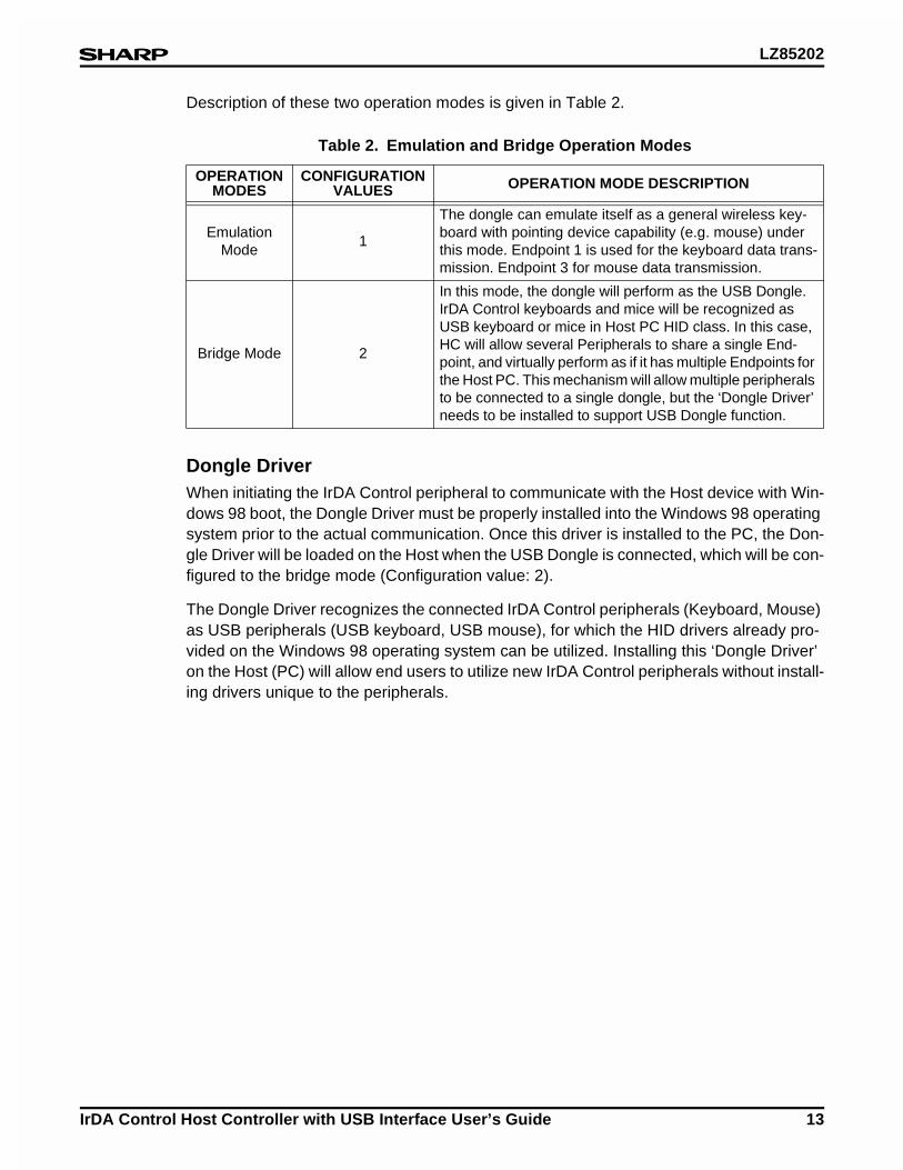
Description of these two operation modes is given in Table 2.
Dongle DriverWhen initiating the IrDA Control peripheral to communicate with the Host device with Win-dows 98 boot, the Dongle Driver must be properly installed into the Windows 98 operating system prior to the actual communication. Once this driver is installed to the PC, the Don-gle Driver will be loaded on the Host when the USB Dongle is connected, which will be con-figured to the bridge mode (Configuration value: 2).
The Dongle Driver recognizes the connected IrDA Control peripherals (Keyboard, Mouse) as USB peripherals (USB keyboard, USB mouse), for which the HID drivers already pro-vided on the Windows 98 operating system can be utilized. Installing this ‘Dongle Driver’ on the Host (PC) will allow end users to utilize new IrDA Control peripherals without install-ing drivers unique to the peripherals.
Table 2. Emulation and Bridge Operation Modes
OPERATION MODES
CONFIGURATION VALUES OPERATION MODE DESCRIPTION
Emulation Mode
1
The dongle can emulate itself as a general wireless key-board with pointing device capability (e.g. mouse) under this mode. Endpoint 1 is used for the keyboard data trans-mission. Endpoint 3 for mouse data transmission.
Bridge Mode 2
In this mode, the dongle will perform as the USB Dongle. IrDA Control keyboards and mice will be recognized as USB keyboard or mice in Host PC HID class. In this case, HC will allow several Peripherals to share a single End-point, and virtually perform as if it has multiple Endpoints for the Host PC. This mechanism will allow multiple peripherals to be connected to a single dongle, but the ‘Dongle Driver’ needs to be installed to support USB Dongle function.
LZ85202
14 IrDA Control Host Controller with USB Interface User’s Guide
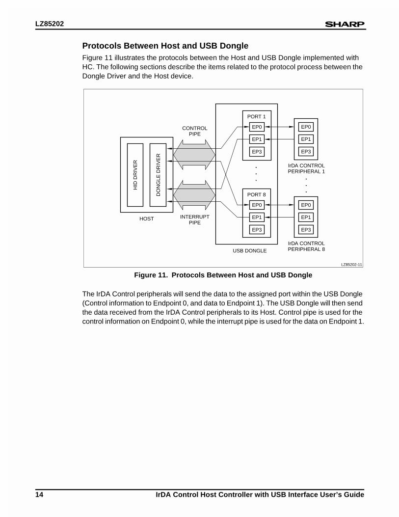
Protocols Between Host and USB DongleFigure 11 illustrates the protocols between the Host and USB Dongle implemented with HC. The following sections describe the items related to the protocol process between the Dongle Driver and the Host device.
The IrDA Control peripherals will send the data to the assigned port within the USB Dongle (Control information to Endpoint 0, and data to Endpoint 1). The USB Dongle will then send the data received from the IrDA Control peripherals to its Host. Control pipe is used for the control information on Endpoint 0, while the interrupt pipe is used for the data on Endpoint 1.
Figure 11. Protocols Between Host and USB Dongle
EP0
EP1
EP3
IrDA CONTROLPERIPHERAL 1
IrDA CONTROLPERIPHERAL 8USB DONGLE
HOST
LZ85202-11
EP0
EP1
EP3
EP0
PORT 8
EP1
EP3
EP0
PORT 1
CONTROLPIPE
INTERRUPTPIPE
DO
NG
LE D
RIV
ER
EP1
EP3
HID
DR
IVE
R ... .
.
.
LZ85202
IrDA Control Host Controller with USB Interface User’s Guide 15
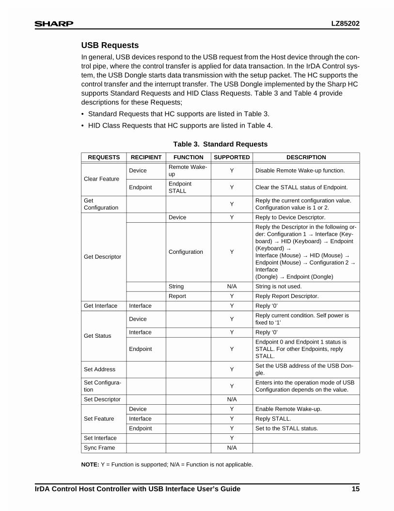
USB RequestsIn general, USB devices respond to the USB request from the Host device through the con-trol pipe, where the control transfer is applied for data transaction. In the IrDA Control sys-tem, the USB Dongle starts data transmission with the setup packet. The HC supports the control transfer and the interrupt transfer. The USB Dongle implemented by the Sharp HC supports Standard Requests and HID Class Requests. Table 3 and Table 4 provide descriptions for these Requests;
• Standard Requests that HC supports are listed in Table 3.
• HID Class Requests that HC supports are listed in Table 4.
NOTE: Y = Function is supported; N/A = Function is not applicable.
Table 3. Standard Requests
REQUESTS RECIPIENT FUNCTION SUPPORTED DESCRIPTION
Clear FeatureDevice
Remote Wake-up
Y Disable Remote Wake-up function.
EndpointEndpoint STALL
Y Clear the STALL status of Endpoint.
Get Configuration
YReply the current configuration value. Configuration value is 1 or 2.
Get Descriptor
Device Y Reply to Device Descriptor.
Configuration Y
Reply the Descriptor in the following or-der: Configuration 1 → Interface (Key-board) → HID (Keyboard) → Endpoint (Keyboard) → Interface (Mouse) → HID (Mouse) → Endpoint (Mouse) → Configuration 2 → Interface (Dongle) → Endpoint (Dongle)
String N/A String is not used.
Report Y Reply Report Descriptor.
Get Interface Interface Y Reply ‘0’
Get Status
Device YReply current condition. Self power is fixed to ‘1’
Interface Y Reply ‘0’
Endpoint YEndpoint 0 and Endpoint 1 status is STALL. For other Endpoints, reply STALL.
Set Address YSet the USB address of the USB Don-gle.
Set Configura-tion
YEnters into the operation mode of USB Configuration depends on the value.
Set Descriptor N/A
Set Feature
Device Y Enable Remote Wake-up.
Interface Y Reply STALL.
Endpoint Y Set to the STALL status.
Set Interface Y
Sync Frame N/A
LZ85202
16 IrDA Control Host Controller with USB Interface User’s Guide
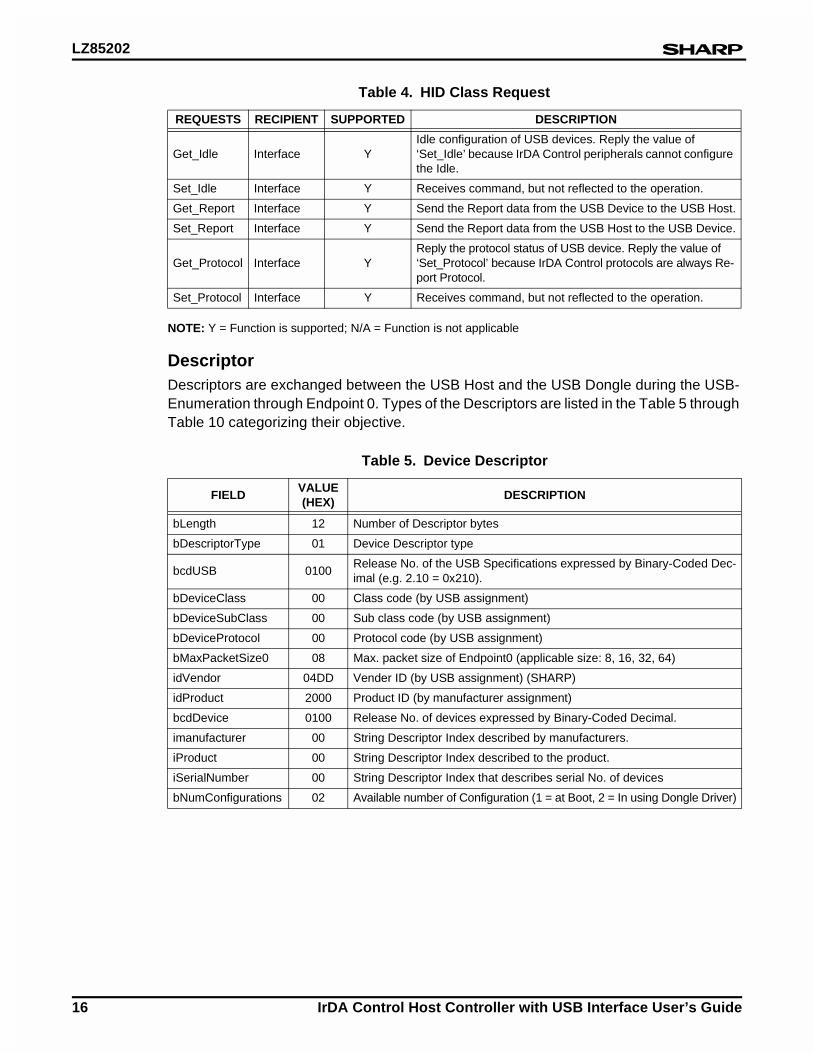
NOTE: Y = Function is supported; N/A = Function is not applicable
DescriptorDescriptors are exchanged between the USB Host and the USB Dongle during the USB-Enumeration through Endpoint 0. Types of the Descriptors are listed in the Table 5 through Table 10 categorizing their objective.
Table 4. HID Class Request
REQUESTS RECIPIENT SUPPORTED DESCRIPTION
Get_Idle Interface YIdle configuration of USB devices. Reply the value of ‘Set_Idle’ because IrDA Control peripherals cannot configure the Idle.
Set_Idle Interface Y Receives command, but not reflected to the operation.
Get_Report Interface Y Send the Report data from the USB Device to the USB Host.
Set_Report Interface Y Send the Report data from the USB Host to the USB Device.
Get_Protocol Interface YReply the protocol status of USB device. Reply the value of ‘Set_Protocol’ because IrDA Control protocols are always Re-port Protocol.
Set_Protocol Interface Y Receives command, but not reflected to the operation.
Table 5. Device Descriptor
FIELDVALUE (HEX)
DESCRIPTION
bLength 12 Number of Descriptor bytes
bDescriptorType 01 Device Descriptor type
bcdUSB 0100Release No. of the USB Specifications expressed by Binary-Coded Dec-imal (e.g. 2.10 = 0x210).
bDeviceClass 00 Class code (by USB assignment)
bDeviceSubClass 00 Sub class code (by USB assignment)
bDeviceProtocol 00 Protocol code (by USB assignment)
bMaxPacketSize0 08 Max. packet size of Endpoint0 (applicable size: 8, 16, 32, 64)
idVendor 04DD Vender ID (by USB assignment) (SHARP)
idProduct 2000 Product ID (by manufacturer assignment)
bcdDevice 0100 Release No. of devices expressed by Binary-Coded Decimal.
imanufacturer 00 String Descriptor Index described by manufacturers.
iProduct 00 String Descriptor Index described to the product.
iSerialNumber 00 String Descriptor Index that describes serial No. of devices
bNumConfigurations 02 Available number of Configuration (1 = at Boot, 2 = In using Dongle Driver)
LZ85202
IrDA Control Host Controller with USB Interface User’s Guide 17
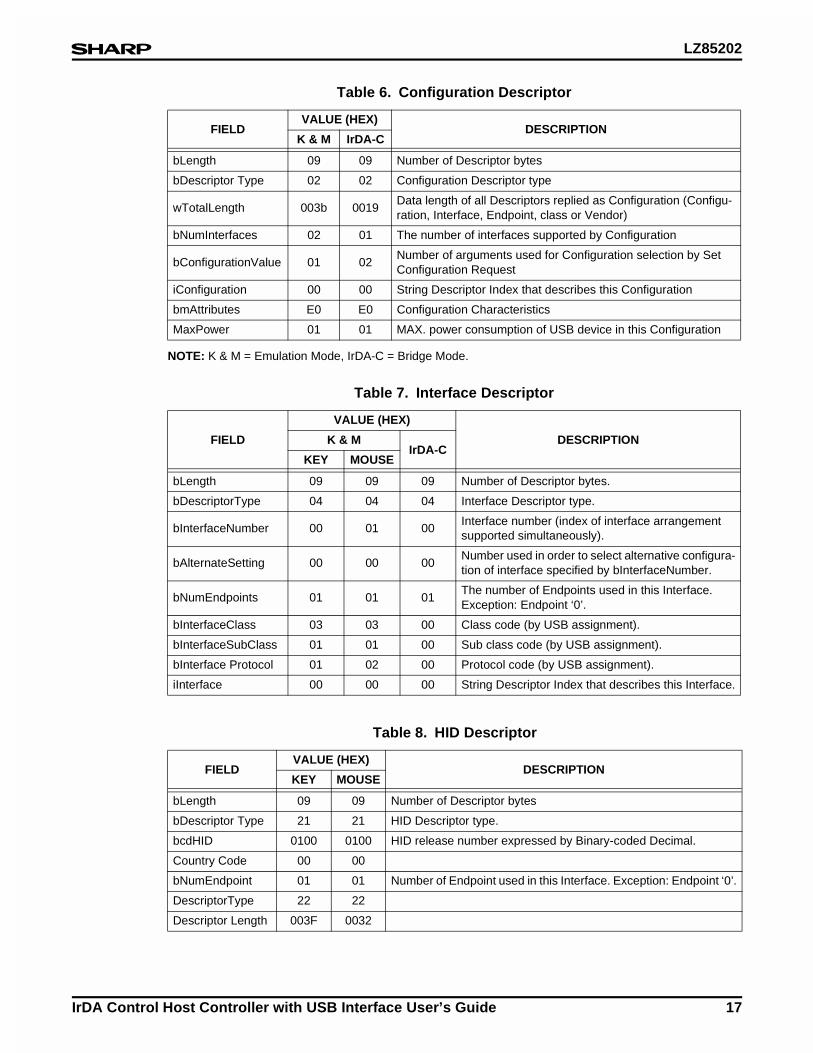
NOTE: K & M = Emulation Mode, IrDA-C = Bridge Mode.
Table 6. Configuration Descriptor
FIELDVALUE (HEX)
DESCRIPTIONK & M IrDA-C
bLength 09 09 Number of Descriptor bytes
bDescriptor Type 02 02 Configuration Descriptor type
wTotalLength 003b 0019Data length of all Descriptors replied as Configuration (Configu-ration, Interface, Endpoint, class or Vendor)
bNumInterfaces 02 01 The number of interfaces supported by Configuration
bConfigurationValue 01 02Number of arguments used for Configuration selection by Set Configuration Request
iConfiguration 00 00 String Descriptor Index that describes this Configuration
bmAttributes E0 E0 Configuration Characteristics
MaxPower 01 01 MAX. power consumption of USB device in this Configuration
Table 7. Interface Descriptor
FIELD
VALUE (HEX)
DESCRIPTIONK & MIrDA-C
KEY MOUSE
bLength 09 09 09 Number of Descriptor bytes.
bDescriptorType 04 04 04 Interface Descriptor type.
bInterfaceNumber 00 01 00Interface number (index of interface arrangement supported simultaneously).
bAlternateSetting 00 00 00Number used in order to select alternative configura-tion of interface specified by bInterfaceNumber.
bNumEndpoints 01 01 01The number of Endpoints used in this Interface. Exception: Endpoint ‘0’.
bInterfaceClass 03 03 00 Class code (by USB assignment).
bInterfaceSubClass 01 01 00 Sub class code (by USB assignment).
bInterface Protocol 01 02 00 Protocol code (by USB assignment).
iInterface 00 00 00 String Descriptor Index that describes this Interface.
Table 8. HID Descriptor
FIELDVALUE (HEX)
DESCRIPTIONKEY MOUSE
bLength 09 09 Number of Descriptor bytes
bDescriptor Type 21 21 HID Descriptor type.
bcdHID 0100 0100 HID release number expressed by Binary-coded Decimal.
Country Code 00 00
bNumEndpoint 01 01 Number of Endpoint used in this Interface. Exception: Endpoint ‘0’.
DescriptorType 22 22
Descriptor Length 003F 0032
LZ85202
18 IrDA Control Host Controller with USB Interface User’s Guide
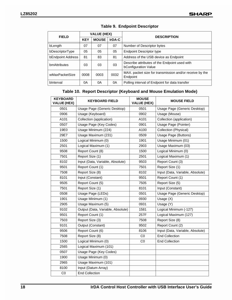
Table 9. Endpoint Descriptor
FIELDVALUE (HEX)
DESCRIPTIONKEY MOUSE IrDA-C
bLength 07 07 07 Number of Descriptor bytes
bDescriptorType 05 05 05 Endpoint Descriptor type
bEndpoint Address 81 83 81 Address of the USB device as Endpoint
bmAttributes 03 03 03Describe attributes of the Endpoint used with bConfiguration Value
wMaxPacketSize 0008 0003 0032MAX. packet size for transmission and/or receive by the Endpoint
bInterval 0A 0A 0A Polling interval of Endpoint for data transfer
Table 10. Report Descriptor (Keyboard and Mouse Emulation Mode)
KEYBOARD VALUE (HEX)
KEYBOARD FIELDMOUSE
VALUE (HEX) MOUSE FIELD
0501 Usage Page (Generic Desktop) 0501 Usage Page (Generic Desktop)
0906 Usage (Keyboard) 0902 Usage (Mouse)
A101 Collection (application) A101 Collection (application)
0507 Usage Page (Key Codes) 0901 Usage Page (Pointer)
19E0 Usage Minimum (224) A100 Collection (Physical)
29E7 Usage Maximum (231) 0509 Usage Page (Buttons)
1500 Logical Minimum (0) 1901 Usage Minimum (01)
2501 Logical Maximum (1) 2903 Usage Maximum (03)
9508 Report Count (8) 1500 Logical Minimum (0)
7501 Report Size (1) 2501 Logical Maximum (1)
8102 Input (Data, Variable, Absolute) 9503 Report Count (3)
9501 Report Count (1) 7501 Report Size (1)
7508 Report Size (8) 8102 Input (Data, Variable, Absolute)
8101 Input (Constant) 9501 Report Count (1)
9505 Report Count (5) 7505 Report Size (5)
7501 Report Size (1) 8101 Input (Constant)
0508 Usage Page (LEDs) 0501 Usage Page (Generic Desktop)
1901 Usage Minimum (1) 0930 Usage (X)
2905 Usage Maximum (5) 0931 Usage (Y)
9102 Output (Data, Variable, Absolute) 1581 Logical Minimum (-127)
9501 Report Count (1) 257F Logical Maximum (127)
7503 Report Size (3) 7508 Report Size (8)
9101 Output (Constant) 9502 Report Count (2)
9506 Report Count (6) 8106 Input (Data, Variable, Absolute)
7508 Report Size (8) C0 End Collection
1500 Logical Minimum (0) C0 End Collection
2565 Logical Maximum (101)
0507 Usage Page (Key Codes)
1900 Usage Minimum (0)
2965 Usage Maximum (101)
8100 Input (Datum Array)
C0 End Collection
LZ85202
IrDA Control Host Controller with USB Interface User’s Guide 19
IrDA Control Protocol Process (IrDA Control Module)There are three communication statuses for the Peripherals in the practical data transac-tion on the IrDA Control subsystem;
1. Enumeration Status. The communication status where dongle starts communication, complete Enumeration process, and then goes into the Sleep status by the Wakeup packet from the Peripheral.
2. Communication Status. The communication status where the dongle polls the enumer-ated IrDA Control peripherals after completion of Bind process. The Host device also executes Hailing for Enumeration as well as Binding periodically.
3. Sleep Status. The communication status where no IrDA Control peripherals are bound, thus no communication occurs between the Host and the Peripherals.
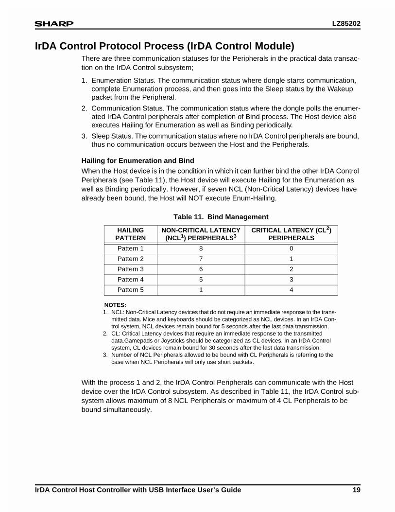
Hailing for Enumeration and BindWhen the Host device is in the condition in which it can further bind the other IrDA Control Peripherals (see Table 11), the Host device will execute Hailing for the Enumeration as well as Binding periodically. However, if seven NCL (Non-Critical Latency) devices have already been bound, the Host will NOT execute Enum-Hailing.
NOTES:1. NCL: Non-Critical Latency devices that do not require an immediate response to the trans-
mitted data. Mice and keyboards should be categorized as NCL devices. In an IrDA Con-trol system, NCL devices remain bound for 5 seconds after the last data transmission.
2. CL: Critical Latency devices that require an immediate response to the transmitted data.Gamepads or Joysticks should be categorized as CL devices. In an IrDA Control system, CL devices remain bound for 30 seconds after the last data transmission.
3. Number of NCL Peripherals allowed to be bound with CL Peripherals is referring to the case when NCL Peripherals will only use short packets.
With the process 1 and 2, the IrDA Control Peripherals can communicate with the Host device over the IrDA Control subsystem. As described in Table 11, the IrDA Control sub-system allows maximum of 8 NCL Peripherals or maximum of 4 CL Peripherals to be bound simultaneously.
Table 11. Bind Management
HAILINGPATTERN
NON-CRITICAL LATENCY (NCL1) PERIPHERALS3
CRITICAL LATENCY (CL2) PERIPHERALS
Pattern 1 8 0
Pattern 2 7 1
Pattern 3 6 2
Pattern 4 5 3
Pattern 5 1 4
LZ85202
20 IrDA Control Host Controller with USB Interface User’s Guide
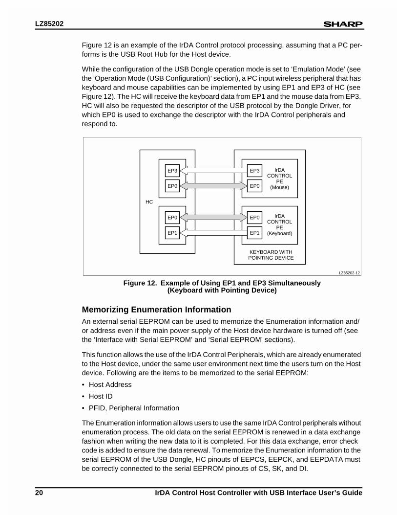
Figure 12 is an example of the IrDA Control protocol processing, assuming that a PC per-forms is the USB Root Hub for the Host device.
While the configuration of the USB Dongle operation mode is set to ‘Emulation Mode’ (see the ‘Operation Mode (USB Configuration)’ section), a PC input wireless peripheral that has keyboard and mouse capabilities can be implemented by using EP1 and EP3 of HC (see Figure 12). The HC will receive the keyboard data from EP1 and the mouse data from EP3. HC will also be requested the descriptor of the USB protocol by the Dongle Driver, for which EP0 is used to exchange the descriptor with the IrDA Control peripherals and respond to.
Memorizing Enumeration InformationAn external serial EEPROM can be used to memorize the Enumeration information and/or address even if the main power supply of the Host device hardware is turned off (see the ‘Interface with Serial EEPROM’ and ‘Serial EEPROM’ sections).
This function allows the use of the IrDA Control Peripherals, which are already enumerated to the Host device, under the same user environment next time the users turn on the Host device. Following are the items to be memorized to the serial EEPROM:
• Host Address
• Host ID
• PFID, Peripheral Information
The Enumeration information allows users to use the same IrDA Control peripherals without enumeration process. The old data on the serial EEPROM is renewed in a data exchange fashion when writing the new data to it is completed. For this data exchange, error check code is added to ensure the data renewal. To memorize the Enumeration information to the serial EEPROM of the USB Dongle, HC pinouts of EEPCS, EEPCK, and EEPDATA must be correctly connected to the serial EEPROM pinouts of CS, SK, and DI.
Figure 12. Example of Using EP1 and EP3 Simultaneously (Keyboard with Pointing Device)
LZ85202-12
EP3
EP0
HC
IrDACONTROL
PE(Mouse)
IrDACONTROL
PE(Keyboard)
KEYBOARD WITHPOINTING DEVICE
EP0
EP1
EP3
EP0
EP0
EP1
LZ85202
IrDA Control Host Controller with USB Interface User’s Guide 21
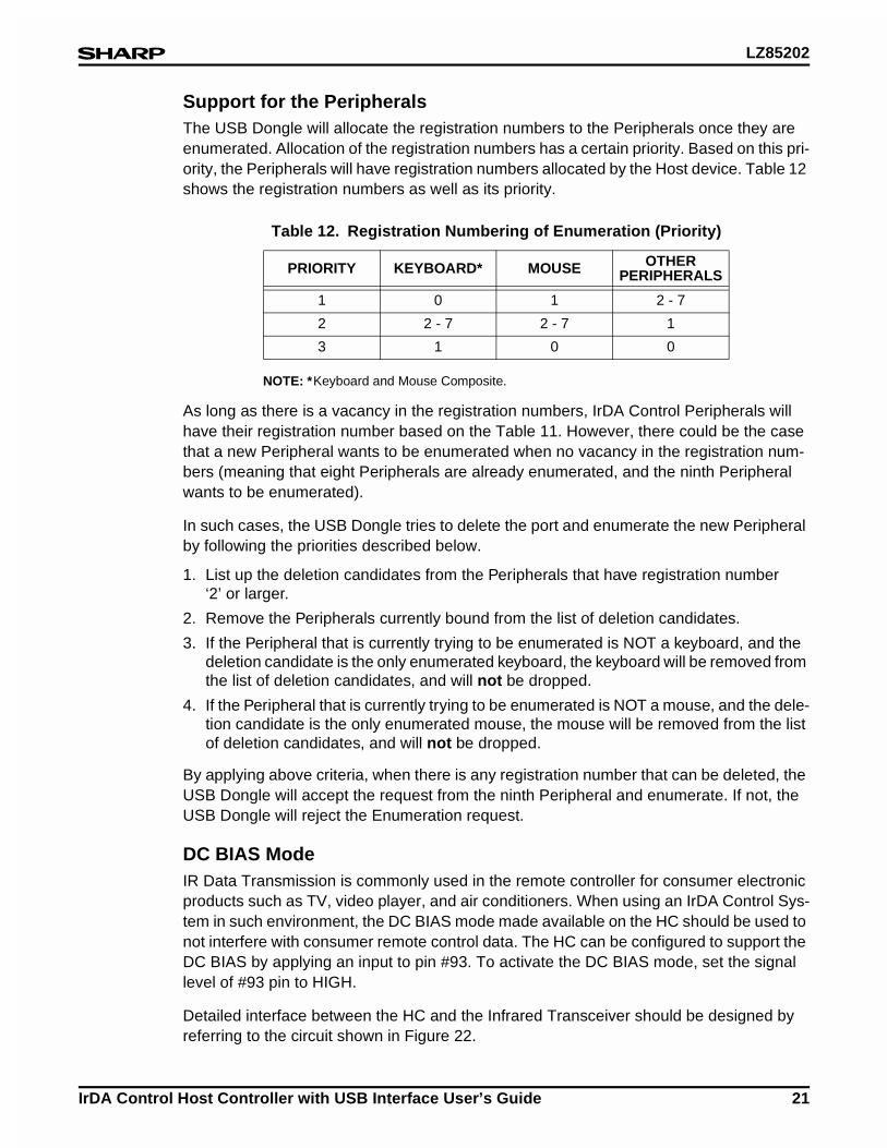
Support for the PeripheralsThe USB Dongle will allocate the registration numbers to the Peripherals once they are enumerated. Allocation of the registration numbers has a certain priority. Based on this pri-ority, the Peripherals will have registration numbers allocated by the Host device. Table 12 shows the registration numbers as well as its priority.
NOTE: *Keyboard and Mouse Composite.
As long as there is a vacancy in the registration numbers, IrDA Control Peripherals will have their registration number based on the Table 11. However, there could be the case that a new Peripheral wants to be enumerated when no vacancy in the registration num-bers (meaning that eight Peripherals are already enumerated, and the ninth Peripheral wants to be enumerated).
In such cases, the USB Dongle tries to delete the port and enumerate the new Peripheral by following the priorities described below.
1. List up the deletion candidates from the Peripherals that have registration number ‘2’ or larger.
2. Remove the Peripherals currently bound from the list of deletion candidates.
3. If the Peripheral that is currently trying to be enumerated is NOT a keyboard, and the deletion candidate is the only enumerated keyboard, the keyboard will be removed from the list of deletion candidates, and will not be dropped.
4. If the Peripheral that is currently trying to be enumerated is NOT a mouse, and the dele-tion candidate is the only enumerated mouse, the mouse will be removed from the list of deletion candidates, and will not be dropped.
By applying above criteria, when there is any registration number that can be deleted, the USB Dongle will accept the request from the ninth Peripheral and enumerate. If not, the USB Dongle will reject the Enumeration request.
DC BIAS ModeIR Data Transmission is commonly used in the remote controller for consumer electronic products such as TV, video player, and air conditioners. When using an IrDA Control Sys-tem in such environment, the DC BIAS mode made available on the HC should be used to not interfere with consumer remote control data. The HC can be configured to support the DC BIAS by applying an input to pin #93. To activate the DC BIAS mode, set the signal level of #93 pin to HIGH.
Detailed interface between the HC and the Infrared Transceiver should be designed by referring to the circuit shown in Figure 22.
Table 12. Registration Numbering of Enumeration (Priority)
PRIORITY KEYBOARD* MOUSE OTHER PERIPHERALS
1 0 1 2 - 7
2 2 - 7 2 - 7 1
3 1 0 0
LZ85202
22 IrDA Control Host Controller with USB Interface User’s Guide
Setting the Host Address (Using DIP Switch)The Host Address is determined after the IrDA Control Host device receives the wakeup packet from the Peripherals. At the same time, the Host ID is also determined. The HC sets the communication controller timer when the wakeup packet is received, and sets the Host Address by random numbers.
In the IrDA Control system, there is a possibility that multiple Host devices have the same Host Address in the reached range because of Host Address generated by random num-bers. Manual configuration of the Host Address by the use of DIP switch may minimize this possibility. If the DIP switch is used, the upper nibble of the Host Address will be set with the 4 bits information of the DIP switch, and the lower nibble will be determined by the random numbers. Using DIP switch, HC configures the Host Address by the following instruction;
1. Observe the DIP switch value first.
2. Attempt to restore the Host Address
When HC is to restore the Host Address, Host Address configuration varies whether the restoration succeeded or failed;
Case A Restoration Failed(A-1) DIP switch value is NOT ‘0’;
→ Upper nibble by DIP switch, lower nibble by random number.
(A-2) DIP switch value is ‘0’;→ All by random number.
Case B Restoration Succeeded(A-1) DIP switch value is NOT ‘0’, and the restored Host Address differs from
that of EEPROM;→ Upper nibble by DIP switch, lower nibble by random number.
(A-2) DIP switch value is ‘0’;→ Use restored Host Address.
For other cases when the DIP switch value is ‘0’, Host Address may be changed by the USB request. In changing the Host Address by the USB request, the upper nibble is con-figured by the USB request, and the lower nibble by the random number.
After all, if the Host Address is changed, HC performs the following configuration;
3. Re-generate the HostID by random number, and initialize the Enumeration Table.
LZ85202
IrDA Control Host Controller with USB Interface User’s Guide 23
USB-IrDA Control Bridge Process (USB-IrDA Bridge Module)The protocol interface for USB and that of IrDA Control deal with different data forms, and the data cannot be directly exchanged between the USB protocol process module and the IrDA Control protocol process module.
As explained, the USB-to-IrDA Control bridge module is required to translate the data pro-cessed by the USB module (or IrDA Control module) into the data that can be handled by the IrDA Control module (or USB module).
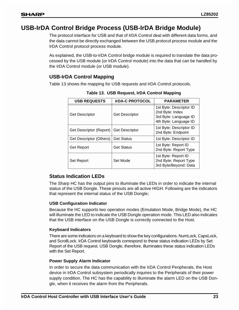
USB-IrDA Control MappingTable 13 shows the mapping for USB requests and IrDA Control protocols.
Status Indication LEDsThe Sharp HC has the output pins to illuminate the LEDs in order to indicate the internal status of the USB Dongle. These pinouts are all active HIGH. Following are the indicators that represent the internal status of the USB Dongle;
USB Configuration IndicatorBecause the HC supports two operation modes (Emulation Mode, Bridge Mode), the HC will illuminate the LED to indicate the USB Dongle operation mode. This LED also indicates that the USB interface on the USB Dongle is correctly connected to the Host.
Keyboard IndicatorsThere are some indicators on a keyboard to show the key configurations. NumLock, CapsLock, and ScrollLock. IrDA Control keyboards correspond to these status indication LEDs by Set Report of the USB request. USB Dongle, therefore, illuminates these status indication LEDs with the Set Report.
Power Supply Alarm IndicatorIn order to secure the data communication with the IrDA Control Peripherals, the Host device in IrDA Control subsystem periodically inquires to the Peripherals of their power supply condition. The HC has the capability to illuminate the alarm LED on the USB Don-gle, when it receives the alarm from the Peripherals.
Table 13. USB Request, IrDA Control Mapping
USB REQUESTS IrDA-C PROTOCOL PARAMETER
Get Descriptor Get Descriptor
1st Byte: Descriptor ID2nd Byte: Index3rd Byte: Language ID4th Byte: Language ID
Get Descriptor (Report) Get Descriptor1st Byte: Descriptor ID2nd Byte: Endpoint
Get Descriptor (Others) Get Status 1st Byte: Descriptor ID
Get Report Get Status1st Byte: Report ID2nd Byte: Report Type
Set Report Set Mode1st Byte: Report ID2nd Byte: Report Type3rd Byte/Beyond: Data

LZ85202
24 IrDA Control Host Controller with USB Interface User’s Guide
Peripheral Power Supply Information
FunctionIn the IrDA Control subsystem, the IrDA Control Peripherals need to have their own power supply to communicate with the Host device over IR. In order to ensure the proper com-munication, the USB-IrDA Control Bridge in the HC inquires about the power supply con-dition of the IrDA Control Peripherals every time they are bound to the Host device. The result will be forwarded to the USB Host via USB.
1. In the event that the Peripheral does not appropriately reply to the inquiry, the HC will regard that the device does not support the Peripheral Power Supply Information func-tion, and will not inquire about the power supply conditions from the next Binding.
2. During the control transfer (USB-Enumeration), HC will inquire about the power supply condition when the current control transfer is completed.
3. If the USB Host requests the HC for the control transfer during the power supply condi-tion inquiry, the HC will respond to the USB request by STALL.
Specifications
1. The HC will individually record the data transaction start time after Binding for each Peripheral. The Host device will then issue ‘Get Status’, after more than one second of time from the recorded data transaction start time.
2. In the parameter of ‘Get Status’ issued by the Host device, 2 bytes of data, which are ‘0x00 (Report ID)’ and ‘0xF0 (Report type)’ are enclosed. The Peripheral Engine in the Peripheral (PE, Sharp P/N: LZ85194) extracts these 2 bytes of data, and report to the peripheral system µP.
3. The Peripheral recognizes above 2 bytes of data as ‘power supply condition inquiry’, and respond to the Host device by 1 byte of data, which are either ‘0x00 (normal)’, ‘0x01 (alarm)’, or ‘0x02 (caution)’.
4. In case that the USB Dongle fails to receive the power supply condition information from the Peripheral, or exceeds the retry attempts for the ‘Get Status’ of the IrDA Control HID LLC layer, the HC will not report the power supply conditions to the USB Host. The USB Dongle will then disable this power supply condition inquiry function and will not inquire the condition at next Binding.
Auto Repeat Cancellation for Keyboard ErrorIn general, keyboards make the desired character appear on the display as long as it sends the ‘key stroke’ data to the Host device. Or, the typed character keeps appearing on the dis-play until the keyboard sends the ‘key release’ code to the Host device. When using a wire-less keyboard, the ‘key release’ code thus needs to be correctly received for the desired operation. Such a case may happen, such as an unexpected disconnection of the keyboard.
The ‘Auto Repeat Cancellation for Keyboard Error’ is a unique function of the HC, which is to prevent the undesired phenomena described above. In the event that the USB Dongle does not receive any data from the IrDA Control keyboard over 220 ms after receiving ‘key stroke’, the USB Dongle automatically sends ‘key release’ code to the Host device.
LZ85202
IrDA Control Host Controller with USB Interface User’s Guide 25
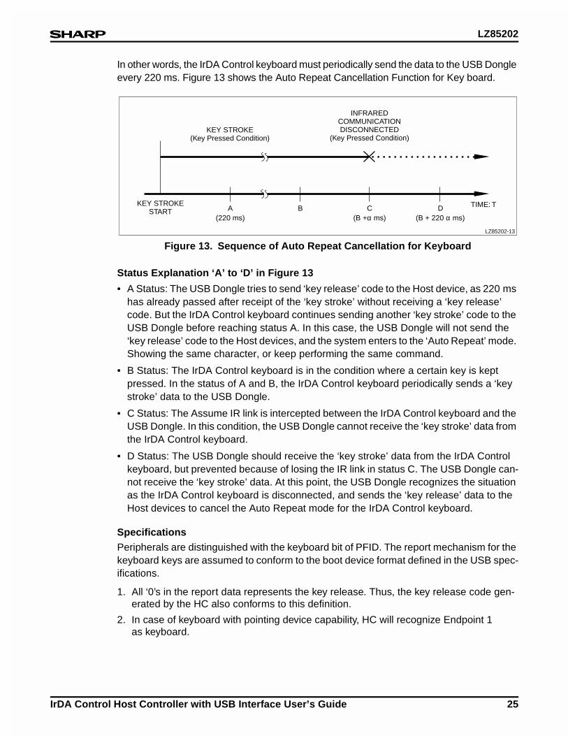
In other words, the IrDA Control keyboard must periodically send the data to the USB Dongle every 220 ms. Figure 13 shows the Auto Repeat Cancellation Function for Key board.
Status Explanation ‘A’ to ‘D’ in Figure 13
• A Status: The USB Dongle tries to send ‘key release’ code to the Host device, as 220 ms has already passed after receipt of the ‘key stroke’ without receiving a ‘key release’ code. But the IrDA Control keyboard continues sending another ‘key stroke’ code to the USB Dongle before reaching status A. In this case, the USB Dongle will not send the ‘key release’ code to the Host devices, and the system enters to the ‘Auto Repeat’ mode. Showing the same character, or keep performing the same command.
• B Status: The IrDA Control keyboard is in the condition where a certain key is kept pressed. In the status of A and B, the IrDA Control keyboard periodically sends a ‘key stroke’ data to the USB Dongle.
• C Status: The Assume IR link is intercepted between the IrDA Control keyboard and the USB Dongle. In this condition, the USB Dongle cannot receive the ‘key stroke’ data from the IrDA Control keyboard.
• D Status: The USB Dongle should receive the ‘key stroke’ data from the IrDA Control keyboard, but prevented because of losing the IR link in status C. The USB Dongle can-not receive the ‘key stroke’ data. At this point, the USB Dongle recognizes the situation as the IrDA Control keyboard is disconnected, and sends the ‘key release’ data to the Host devices to cancel the Auto Repeat mode for the IrDA Control keyboard.
SpecificationsPeripherals are distinguished with the keyboard bit of PFID. The report mechanism for the keyboard keys are assumed to conform to the boot device format defined in the USB spec-ifications.
1. All ‘0’s in the report data represents the key release. Thus, the key release code gen-erated by the HC also conforms to this definition.
2. In case of keyboard with pointing device capability, HC will recognize Endpoint 1 as keyboard.
Figure 13. Sequence of Auto Repeat Cancellation for Keyboard
LZ85202-13
(220 ms) (B +α ms) (B + 220 α ms)A
KEY STROKESTART
KEY STROKE(Key Pressed Condition)
INFRAREDCOMMUNICATIONDISCONNECTED
(Key Pressed Condition)
B C D TIME: T
LZ85202
26 IrDA Control Host Controller with USB Interface User’s Guide
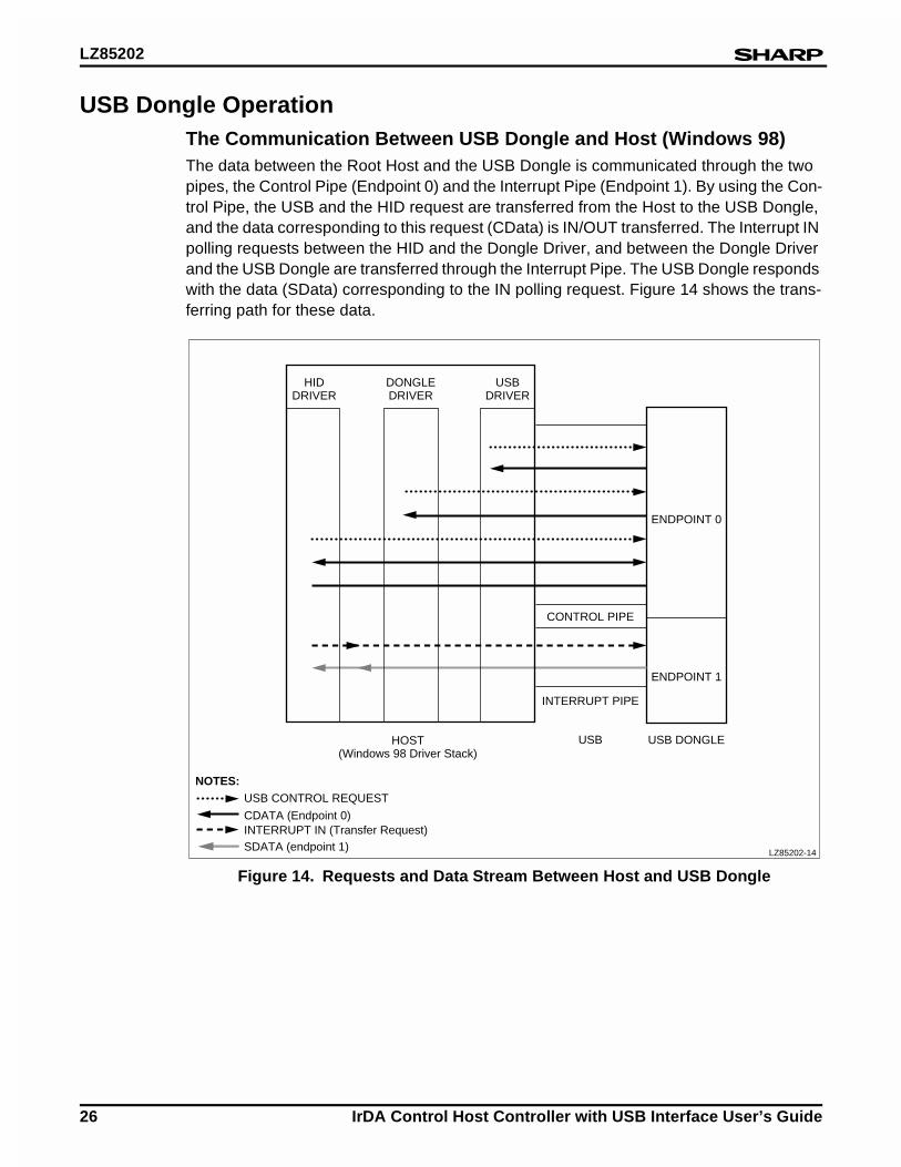
USB Dongle OperationThe Communication Between USB Dongle and Host (Windows 98)The data between the Root Host and the USB Dongle is communicated through the two pipes, the Control Pipe (Endpoint 0) and the Interrupt Pipe (Endpoint 1). By using the Con-trol Pipe, the USB and the HID request are transferred from the Host to the USB Dongle, and the data corresponding to this request (CData) is IN/OUT transferred. The Interrupt IN polling requests between the HID and the Dongle Driver, and between the Dongle Driver and the USB Dongle are transferred through the Interrupt Pipe. The USB Dongle responds with the data (SData) corresponding to the IN polling request. Figure 14 shows the trans-ferring path for these data.
Figure 14. Requests and Data Stream Between Host and USB Dongle
ENDPOINT 0
USB CONTROL REQUEST
NOTES:
CDATA (Endpoint 0)INTERRUPT IN (Transfer Request)SDATA (endpoint 1)
HIDDRIVER
DONGLEDRIVER
HOST(Windows 98 Driver Stack)
USBDRIVER
ENDPOINT 1
CONTROL PIPE
INTERRUPT PIPE
USB USB DONGLE
LZ85202-14
LZ85202
IrDA Control Host Controller with USB Interface User’s Guide 27
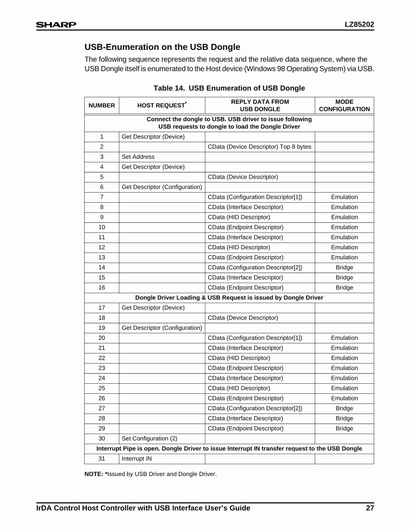
USB-Enumeration on the USB DongleThe following sequence represents the request and the relative data sequence, where the USB Dongle itself is enumerated to the Host device (Windows 98 Operating System) via USB.
NOTE: *Issued by USB Driver and Dongle Driver.
Table 14. USB Enumeration of USB Dongle
NUMBER HOST REQUEST* REPLY DATA FROM USB DONGLE
MODE CONFIGURATION
Connect the dongle to USB. USB driver to issue following USB requests to dongle to load the Dongle Driver
1 Get Descriptor (Device)
2 CData (Device Descriptor) Top 8 bytes
3 Set Address
4 Get Descriptor (Device)
5 CData (Device Descriptor)
6 Get Descriptor (Configuration)
7 CData (Configuration Descriptor[1]) Emulation
8 CData (Interface Descriptor) Emulation
9 CData (HID Descriptor) Emulation
10 CData (Endpoint Descriptor) Emulation
11 CData (Interface Descriptor) Emulation
12 CData (HID Descriptor) Emulation
13 CData (Endpoint Descriptor) Emulation
14 CData (Configuration Descriptor[2]) Bridge
15 CData (Interface Descriptor) Bridge
16 CData (Endpoint Descriptor) Bridge
Dongle Driver Loading & USB Request is issued by Dongle Driver
17 Get Descriptor (Device)
18 CData (Device Descriptor)
19 Get Descriptor (Configuration)
20 CData (Configuration Descriptor[1]) Emulation
21 CData (Interface Descriptor) Emulation
22 CData (HID Descriptor) Emulation
23 CData (Endpoint Descriptor) Emulation
24 CData (Interface Descriptor) Emulation
25 CData (HID Descriptor) Emulation
26 CData (Endpoint Descriptor) Emulation
27 CData (Configuration Descriptor[2]) Bridge
28 CData (Interface Descriptor) Bridge
29 CData (Endpoint Descriptor) Bridge
30 Set Configuration (2)
Interrupt Pipe is open. Dongle Driver to issue Interrupt IN transfer request to the USB Dongle
31 Interrupt IN
LZ85202
28 IrDA Control Host Controller with USB Interface User’s Guide
USB-Enumeration for PeripheralsTable 15 represents the request and the relative data sequence between the Host device (Windows 98 Operating System) and the USB Dongle, where the USB Dongle is USB-Enumerated to the Host, and the IrDA Control Peripheral is newly bound under the condi-tion that USB Dongle is operating at Configuration [2] (Bridge Mode).
Table 15. USB Enumeration of IrDA Control Peripherals
NUMBERREQUEST ISSUED BY
HID DRIVER
REQUEST ISSUED BY DONGLE DRIVER AND REPLY DATA
REPLY DATA FROM USB DONGLE
The new peripheral is bound.
1 Interrupt IN
2SData (Trigger of USB-Enumeration)
3 Get Descriptor (Device)
4 CData (Device Descriptor)
5 Get Descriptor (Configuration)
6 CData (Configuration Descriptor)
7 Get Descriptor (IrDA Control)
8 CData (IrDA-C Descriptor)
Loading the HID Driver (HID Class driver, etc.)
9 Get Descriptor (Device) CData (Device)
10Get Descriptor(Configuration)
CData (Configuration)
11Get Descriptor(Configuration)
CData (Configuration)
12 Set Configuration [1]
13 Set Idle
14 Set Idle
15 Get Descriptor (Report)
16 Get Descriptor (Report)
17 CData (Report Descriptor)
18 Interrupt IN
19 Set Feature (Endpoint Enable)
After the Set Future, Polling for IrDA Control Peripheral starts.
20 Interrupt IN
21 SData (Data from the Peripheral)
LZ85202
IrDA Control Host Controller with USB Interface User’s Guide 29
Dongle Driver RequestThere are two types of USB requests issued by the Dongle Driver to the dongle in the Enu-meration for USB Dongle and IrDA Control Peripheral.
• Get Descriptor (Device, Configuration, IrDA Control, Report, String)
• Set Feature
These are Vendor Specific requests. The Peripheral enumeration recognition information is set to the wValue and wIndex of the setup packet.
HID Driver RequestThere are five types of requests issued by the HID driver to the Dongle Driver (dongle) in the Enumeration for USB Dongle and IrDA Control Peripheral.
• Get Descriptor (Device, Configuration)
• Get Descriptor (Report)
• Set Configuration
• Set Idle
• Set Report (depends on the IrDA Control Peripheral. There is no information in Table x)
The Get Descriptor is a USB standard request.The Dongle Driver corresponding to the HID request provides the data. This is because the Dongle Driver memorizes the data, such as Device, Configuration and IrDA Control Descriptor, which is exchanged just after a IrDA Control Peripheral is bound.
NOTE: For the details of each requests, see the USB and HID class specifications.
LZ85202
30 IrDA Control Host Controller with USB Interface User’s Guide
Pinouts
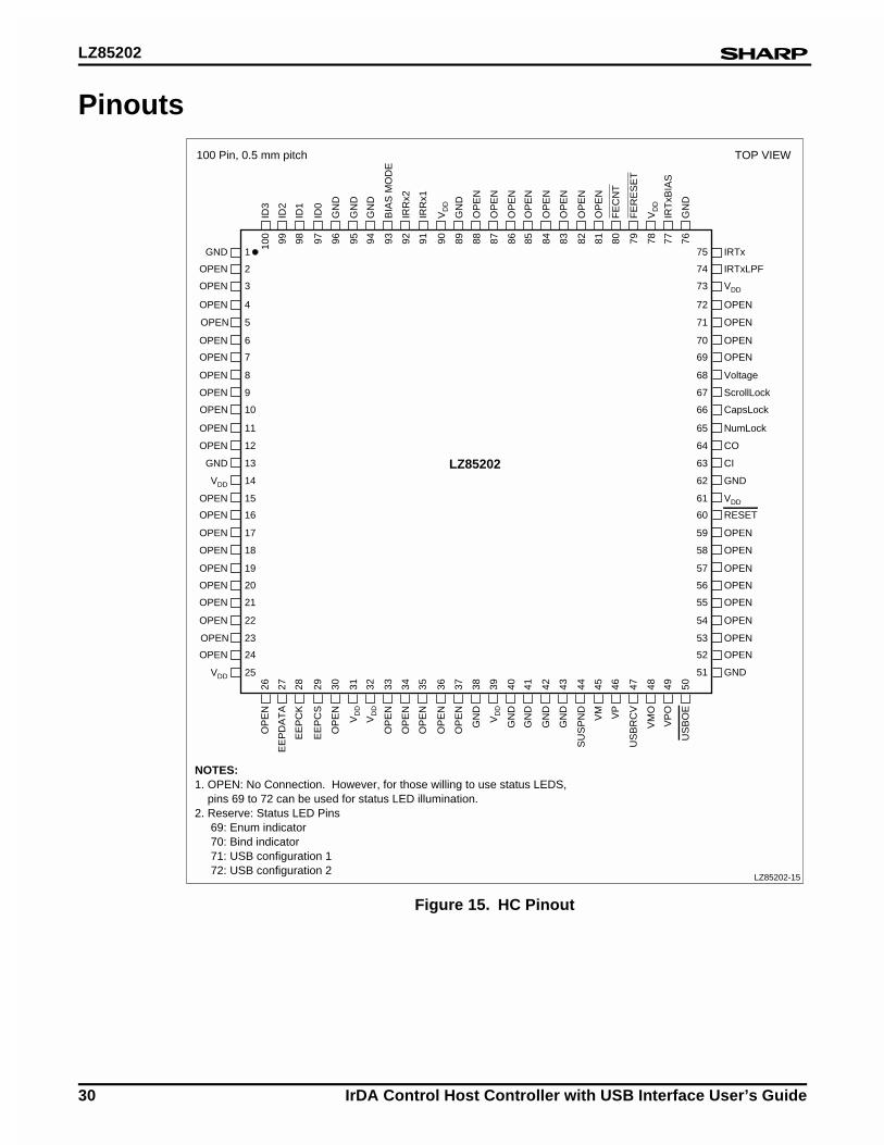
Figure 15. HC Pinout
TOP VIEW100 Pin, 0.5 mm pitch
2
3
4
5
8
9
OPEN
OPEN
OPEN
OPEN
75
72
69
6
7OPEN
OPEN
74
73
OPEN
OPEN
IRTxLPF
OPEN
10
11
12
VDD
13
71
CI
70
GND
OPEN
14
15
16
17
18
19
20
66
63
68
67
65
64
OPEN
OPEN
OPEN
OPEN
OPEN
OPEN
OPEN
OPEN
VDD
OPEN OPEN
OPEN
Voltage
CapsLock
ScrollLock
RESET
1
OPEN
GND IRTx
21
22
23
24OPEN
25VDD
OPEN
OPEN
OPEN
61
OPEN
62
OPEN
58
60
59
57
56
OPEN
OPEN
OPEN
OPEN
OPEN
GND
NumLock
CO
VDD
54
55
53
52
GND51
27 28 29 30 33 34
OP
EN
OP
EN
EE
PC
S
EE
PC
K
31 32V
DD
VD
D
35 36 37 38 39 40 41 42 43 44 45
GN
D
SU
SP
ND
GN
D
GN
D
GN
D
VD
D
VM
26
EE
PD
AT
A
OP
EN
46 47 48 49V
PO
50U
SB
OE
VM
OVP
US
BR
CV
OP
EN
OP
EN
OP
EN
OP
EN
GN
D
100 97 9499 98
ID0
GN
D
ID2
GN
D
ID1
96
OP
EN
95
OP
EN
GN
D
91 8893 92 90 89
OP
EN
OP
EN
OP
EN
OP
EN
FE
CN
T
BIA
S M
OD
E
IRR
x1
IRR
x2
OP
EN
ID3
86
VD
D
87
FE
RE
SE
T
8385 84 82 81
IRT
xBIA
S
VD
D
GN
D
OP
EN
7980 78 77
GN
D76
LZ85202
LZ85202-15
NOTES:1. OPEN: No Connection. However, for those willing to use status LEDS, pins 69 to 72 can be used for status LED illumination.2. Reserve: Status LED Pins 69: Enum indicator 70: Bind indicator 71: USB configuration 1 72: USB configuration 2
LZ85202
IrDA Control Host Controller with USB Interface User’s Guide 31
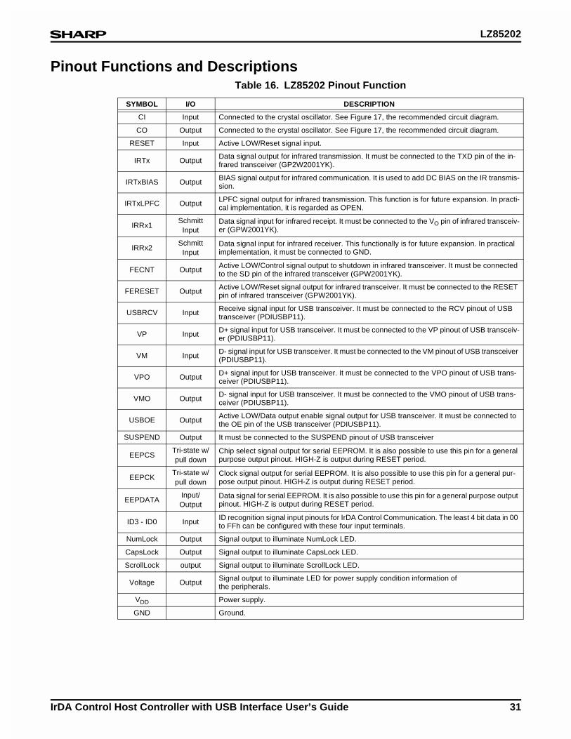
Pinout Functions and DescriptionsTable 16. LZ85202 Pinout Function
SYMBOL I/O DESCRIPTION
CI Input Connected to the crystal oscillator. See Figure 17, the recommended circuit diagram.
CO Output Connected to the crystal oscillator. See Figure 17, the recommended circuit diagram.
RESET Input Active LOW/Reset signal input.
IRTx Output Data signal output for infrared transmission. It must be connected to the TXD pin of the in-frared transceiver (GP2W2001YK).
IRTxBIAS Output BIAS signal output for infrared communication. It is used to add DC BIAS on the IR transmis-sion.
IRTxLPFC Output LPFC signal output for infrared transmission. This function is for future expansion. In practi-cal implementation, it is regarded as OPEN.
IRRx1Schmitt
InputData signal input for infrared receipt. It must be connected to the VO pin of infrared transceiv-er (GPW2001YK).
IRRx2Schmitt
InputData signal input for infrared receiver. This functionally is for future expansion. In practical implementation, it must be connected to GND.
FECNT Output Active LOW/Control signal output to shutdown in infrared transceiver. It must be connected to the SD pin of the infrared transceiver (GPW2001YK).
FERESET Output Active LOW/Reset signal output for infrared transceiver. It must be connected to the RESET pin of infrared transceiver (GPW2001YK).
USBRCV Input Receive signal input for USB transceiver. It must be connected to the RCV pinout of USB transceiver (PDIUSBP11).
VP Input D+ signal input for USB transceiver. It must be connected to the VP pinout of USB transceiv-er (PDIUSBP11).
VM Input D- signal input for USB transceiver. It must be connected to the VM pinout of USB transceiver (PDIUSBP11).
VPO Output D+ signal input for USB transceiver. It must be connected to the VPO pinout of USB trans-ceiver (PDIUSBP11).
VMO Output D- signal input for USB transceiver. It must be connected to the VMO pinout of USB trans-ceiver (PDIUSBP11).
USBOE Output Active LOW/Data output enable signal output for USB transceiver. It must be connected to the OE pin of the USB transceiver (PDIUSBP11).
SUSPEND Output It must be connected to the SUSPEND pinout of USB transceiver
EEPCSTri-state w/pull down
Chip select signal output for serial EEPROM. It is also possible to use this pin for a general purpose output pinout. HIGH-Z is output during RESET period.
EEPCKTri-state w/pull down
Clock signal output for serial EEPROM. It is also possible to use this pin for a general pur-pose output pinout. HIGH-Z is output during RESET period.
EEPDATAInput/Output
Data signal for serial EEPROM. It is also possible to use this pin for a general purpose output pinout. HIGH-Z is output during RESET period.
ID3 - ID0 Input ID recognition signal input pinouts for IrDA Control Communication. The least 4 bit data in 00 to FFh can be configured with these four input terminals.
NumLock Output Signal output to illuminate NumLock LED.
CapsLock Output Signal output to illuminate CapsLock LED.
ScrollLock output Signal output to illuminate ScrollLock LED.
Voltage Output Signal output to illuminate LED for power supply condition information ofthe peripherals.
VDD Power supply.
GND Ground.
LZ85202
32 IrDA Control Host Controller with USB Interface User’s Guide
Block Diagram
CPUThis CPU controls all HC functionality.
Figure 16. HC Block Diagram
LZ85202-16
PLL
CI CO
ROM
RAM PERIPHERAL
ADDRESS BUSDATA BUS
CONTROL SIGNAL
CPU
USB
USBRCV
VP
VM
USBOE
VPO
VMO
SUSPND
IrBC
IRRx1
IRRx2
IRTx
IRTxBIAS
IRTxLPFC
FECNT
FERESET
PORT
ID0 - ID3
NumLock
CapsLock
ScrollLock
EEPCS
EEPCK
Voltage
EEPDATA

LZ85202
IrDA Control Host Controller with USB Interface User’s Guide 33
PLL (Phase Lock Loop) and CG (Clock Generator)The internal PLL generates the master oscillation for the HC from the external 12 MHz crystal connected to the CI pin and CO pin. The generated signal supplies the clock signals required for the internal functions of the HC.
In addition, when the RESET signal is asserted to the HC, clock signals will be supplied to the internal circuit after the PLL counts 65535 clock cycles.
USB (Universal Serial Bus)The USB block is a USB device controller for devices that support the full speed of 12 Mbps. Endpoints and the maximum packet size (FIFO size) are described in Table 17.
Figure 17. HC Recommended Oscillation Circuit
CI
CO
LZ85202-22
22 pF
12 MHz 100 kΩ
22 pF
NOTE: Characteristic evaluation of each crystal oscillator is recommended. Crystal oscillator, capacitor, and resistor should be mounted close to the LSI.
Table 17. USB Maximum Packet Sizes
ITEM DESCRIPTION I/O MAXIMUM PACKET SIZE
Endpoint0 :ControlOut 8 bytes
In 8 bytes
Endpoint1 :Bulk/Interrupt In 64 bytes
Endpoint2 :Bulk/Interrupt Out 64 bytes
Endpoint3 :Bulk/Interrupt In 8 bytes
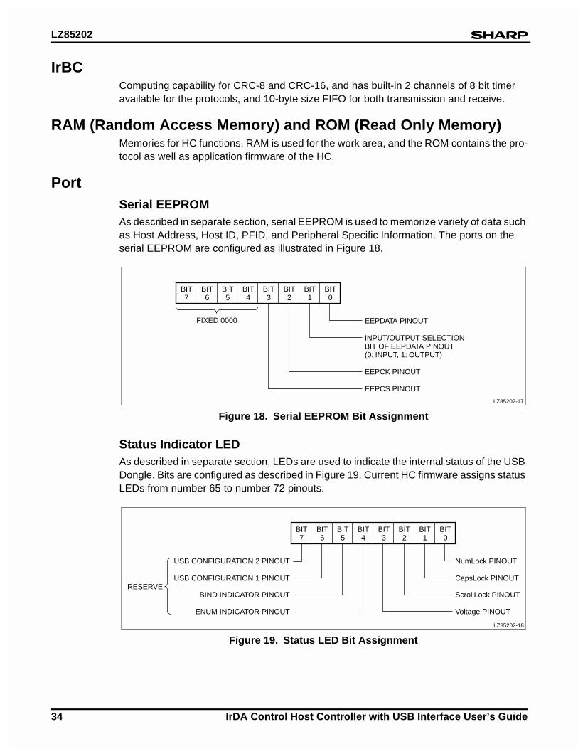
LZ85202
34 IrDA Control Host Controller with USB Interface User’s Guide
IrBCComputing capability for CRC-8 and CRC-16, and has built-in 2 channels of 8 bit timer available for the protocols, and 10-byte size FIFO for both transmission and receive.
RAM (Random Access Memory) and ROM (Read Only Memory)Memories for HC functions. RAM is used for the work area, and the ROM contains the pro-tocol as well as application firmware of the HC.
PortSerial EEPROMAs described in separate section, serial EEPROM is used to memorize variety of data such as Host Address, Host ID, PFID, and Peripheral Specific Information. The ports on the serial EEPROM are configured as illustrated in Figure 18.
Status Indicator LEDAs described in separate section, LEDs are used to indicate the internal status of the USB Dongle. Bits are configured as described in Figure 19. Current HC firmware assigns status LEDs from number 65 to number 72 pinouts.
Figure 18. Serial EEPROM Bit Assignment
BIT7
BIT6
FIXED 0000
BIT5
BIT4
BIT3
BIT2
BIT1
BIT0
EEPDATA PINOUT
EEPCK PINOUT
EEPCS PINOUT
INPUT/OUTPUT SELECTIONBIT OF EEPDATA PINOUT(0: INPUT, 1: OUTPUT)
LZ85202-17
Figure 19. Status LED Bit Assignment
BIT7
BIT6
RESERVE
BIT5
BIT4
BIT3
BIT2
BIT1
BIT0
NumLock PINOUT
ScrollLock PINOUT
Voltage PINOUT
CapsLock PINOUT
USB CONFIGURATION 2 PINOUT
BIND INDICATOR PINOUT
ENUM INDICATOR PINOUT
USB CONFIGURATION 1 PINOUT
LZ85202-18
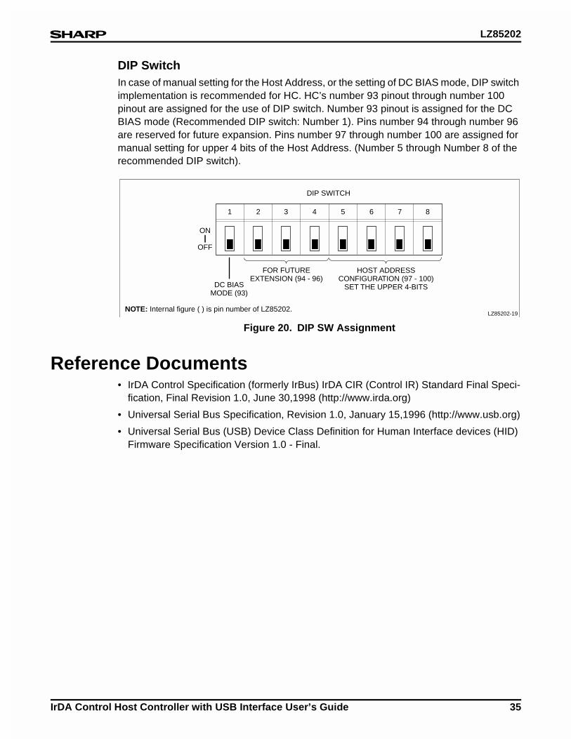
LZ85202
IrDA Control Host Controller with USB Interface User’s Guide 35
DIP SwitchIn case of manual setting for the Host Address, or the setting of DC BIAS mode, DIP switch implementation is recommended for HC. HC’s number 93 pinout through number 100 pinout are assigned for the use of DIP switch. Number 93 pinout is assigned for the DC BIAS mode (Recommended DIP switch: Number 1). Pins number 94 through number 96 are reserved for future expansion. Pins number 97 through number 100 are assigned for manual setting for upper 4 bits of the Host Address. (Number 5 through Number 8 of the recommended DIP switch).
Reference Documents• IrDA Control Specification (formerly IrBus) IrDA CIR (Control IR) Standard Final Speci-
fication, Final Revision 1.0, June 30,1998 (http://www.irda.org)
• Universal Serial Bus Specification, Revision 1.0, January 15,1996 (http://www.usb.org)
• Universal Serial Bus (USB) Device Class Definition for Human Interface devices (HID) Firmware Specification Version 1.0 - Final.
Figure 20. DIP SW Assignment
FOR FUTUREEXTENSION (94 - 96)
DC BIASMODE (93)
ON
OFF
DIP SWITCH
NOTE: Internal figure ( ) is pin number of LZ85202.
HOST ADDRESSCONFIGURATION (97 - 100)
SET THE UPPER 4-BITS
1 2 3 4 5 6 7 8
LZ85202-19
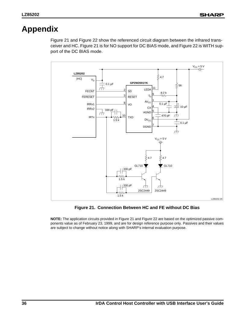
LZ85202
36 IrDA Control Host Controller with USB Interface User’s Guide
AppendixFigure 21 and Figure 22 show the referenced circuit diagram between the infrared trans-ceiver and HC. Figure 21 is for NO support for DC BIAS mode, and Figure 22 is WITH sup-port of the DC BIAS mode.
NOTE: The application circuits provided in Figure 21 and Figure 22 are based on the optimized passive com-ponents value as of February 23, 1999, and are for design reference purpose only. Passives and their valuesare subject to change without notice along with SHARP’s internal evaluation purpose.
Figure 21. Connection Between HC and FE without DC Bias
VD
FECNT
[HC]
LZ85202
GP2W2001YK
FERESET
IRRx1
IRRx2
IRTx
SD
RESET
VO
LEDA
fO
AVCC
VCC = 5 V
VCC = 5 V
CX
AGND
DVCC
DGND
TXD
4.7
56
4.7
8.2 k
470 pF
0.1 µF10 µF
0.1 µF
+
330 pF
0.1 µF
1.5 k
10
4.7
330 pF
1.5 k
330 pF
1.5 k
11
9
1
4
5
6
7
8
3
2
GL710GL710
2SC24492SC2449
LZ85202-20
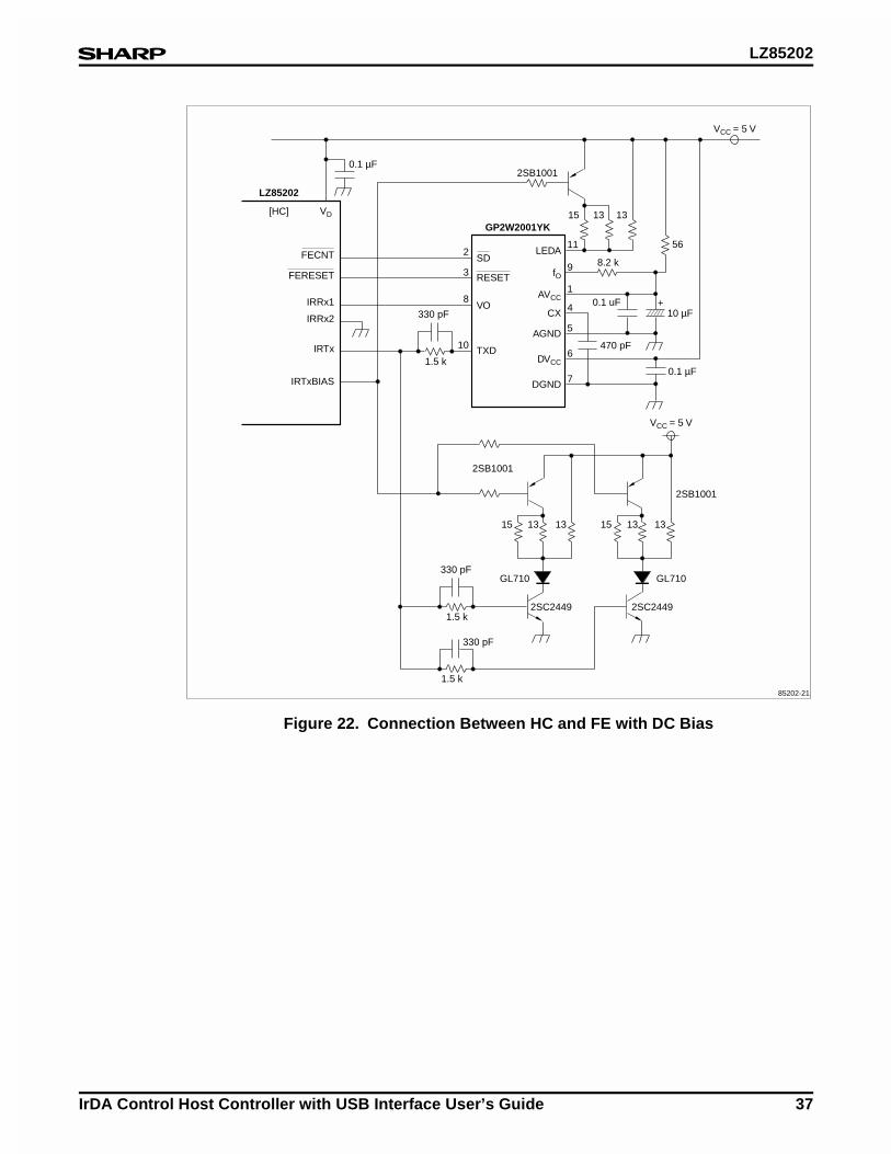
LZ85202
IrDA Control Host Controller with USB Interface User’s Guide 37
Figure 22. Connection Between HC and FE with DC Bias
VD
FECNT
[HC]
LZ85202
GP2W2001YK
FERESET
IRRx1
IRRx2
IRTx
IRTxBIAS
SD
RESET
VO
LEDA
fO
AVCC
VCC = 5 V
VCC = 5 V
CX
AGND
DVCC
DGND
TXD
15 13 13
56
13
8.2 k
470 pF
0.1 uF10 µF
0.1 µF
+
2SB1001
330 pF
0.1 µF
1.5 k
10
1315 13 1315
330 pF
1.5 k
330 pF
1.5 k
11
9
1
4
5
6
7
8
3
2
2SB1001
GL710GL710
2SC2449 2SC2449
2SB1001
85202-21
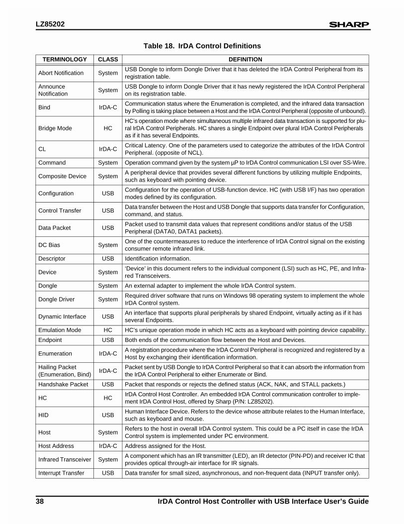
LZ85202
38 IrDA Control Host Controller with USB Interface User’s Guide
Table 18. IrDA Control Definitions
TERMINOLOGY CLASS DEFINITION
Abort Notification SystemUSB Dongle to inform Dongle Driver that it has deleted the IrDA Control Peripheral from its registration table.
Announce Notification
SystemUSB Dongle to inform Dongle Driver that it has newly registered the IrDA Control Peripheral on its registration table.
Bind IrDA-CCommunication status where the Enumeration is completed, and the infrared data transaction by Polling is taking place between a Host and the IrDA Control Peripheral (opposite of unbound).
Bridge Mode HCHC’s operation mode where simultaneous multiple infrared data transaction is supported for plu-ral IrDA Control Peripherals. HC shares a single Endpoint over plural IrDA Control Peripherals as if it has several Endpoints.
CL IrDA-CCritical Latency. One of the parameters used to categorize the attributes of the IrDA Control Peripheral. (opposite of NCL).
Command System Operation command given by the system µP to IrDA Control communication LSI over SS-Wire.
Composite Device SystemA peripheral device that provides several different functions by utilizing multiple Endpoints, such as keyboard with pointing device.
Configuration USBConfiguration for the operation of USB-function device. HC (with USB I/F) has two operation modes defined by its configuration.
Control Transfer USBData transfer between the Host and USB Dongle that supports data transfer for Configuration, command, and status.
Data Packet USBPacket used to transmit data values that represent conditions and/or status of the USB Peripheral (DATA0, DATA1 packets).
DC Bias SystemOne of the countermeasures to reduce the interference of IrDA Control signal on the existing consumer remote infrared link.
Descriptor USB Identification information.
Device System‘Device’ in this document refers to the individual component (LSI) such as HC, PE, and Infra-red Transceivers.
Dongle System An external adapter to implement the whole IrDA Control system.
Dongle Driver SystemRequired driver software that runs on Windows 98 operating system to implement the whole IrDA Control system.
Dynamic Interface USBAn interface that supports plural peripherals by shared Endpoint, virtually acting as if it has several Endpoints.
Emulation Mode HC HC’s unique operation mode in which HC acts as a keyboard with pointing device capability.
Endpoint USB Both ends of the communication flow between the Host and Devices.
Enumeration IrDA-CA registration procedure where the IrDA Control Peripheral is recognized and registered by a Host by exchanging their identification information.
Hailing Packet (Enumeration, Bind)
IrDA-CPacket sent by USB Dongle to IrDA Control Peripheral so that it can absorb the information from the IrDA Control Peripheral to either Enumerate or Bind.
Handshake Packet USB Packet that responds or rejects the defined status (ACK, NAK, and STALL packets.)
HC HCIrDA Control Host Controller. An embedded IrDA Control communication controller to imple-ment IrDA Control Host, offered by Sharp (P/N: LZ85202).
HID USBHuman Interface Device. Refers to the device whose attribute relates to the Human Interface, such as keyboard and mouse.
Host SystemRefers to the host in overall IrDA Control system. This could be a PC itself in case the IrDA Control system is implemented under PC environment.
Host Address IrDA-C Address assigned for the Host.
Infrared Transceiver SystemA component which has an IR transmitter (LED), an IR detector (PIN-PD) and receiver IC that provides optical through-air interface for IR signals.
Interrupt Transfer USB Data transfer for small sized, asynchronous, and non-frequent data (INPUT transfer only).
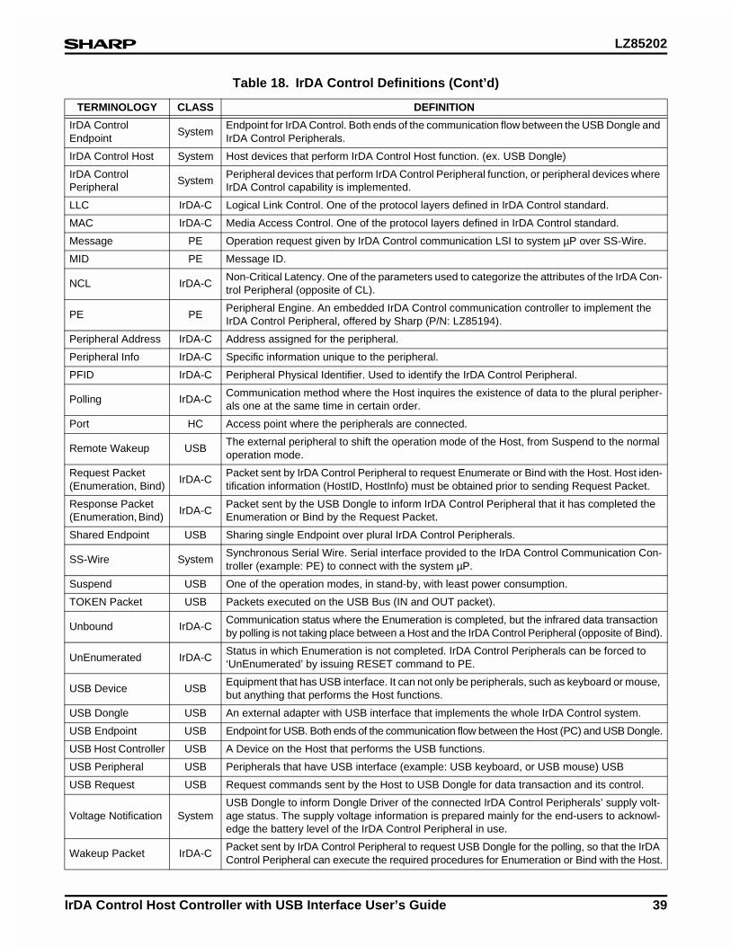
LZ85202
IrDA Control Host Controller with USB Interface User’s Guide 39
IrDA Control Endpoint
SystemEndpoint for IrDA Control. Both ends of the communication flow between the USB Dongle and IrDA Control Peripherals.
IrDA Control Host System Host devices that perform IrDA Control Host function. (ex. USB Dongle)
IrDA Control Peripheral
SystemPeripheral devices that perform IrDA Control Peripheral function, or peripheral devices where IrDA Control capability is implemented.
LLC IrDA-C Logical Link Control. One of the protocol layers defined in IrDA Control standard.
MAC IrDA-C Media Access Control. One of the protocol layers defined in IrDA Control standard.
Message PE Operation request given by IrDA Control communication LSI to system µP over SS-Wire.
MID PE Message ID.
NCL IrDA-CNon-Critical Latency. One of the parameters used to categorize the attributes of the IrDA Con-trol Peripheral (opposite of CL).
PE PEPeripheral Engine. An embedded IrDA Control communication controller to implement the IrDA Control Peripheral, offered by Sharp (P/N: LZ85194).
Peripheral Address IrDA-C Address assigned for the peripheral.
Peripheral Info IrDA-C Specific information unique to the peripheral.
PFID IrDA-C Peripheral Physical Identifier. Used to identify the IrDA Control Peripheral.
Polling IrDA-CCommunication method where the Host inquires the existence of data to the plural peripher-als one at the same time in certain order.
Port HC Access point where the peripherals are connected.
Remote Wakeup USBThe external peripheral to shift the operation mode of the Host, from Suspend to the normal operation mode.
Request Packet (Enumeration, Bind)
IrDA-CPacket sent by IrDA Control Peripheral to request Enumerate or Bind with the Host. Host iden-tification information (HostID, HostInfo) must be obtained prior to sending Request Packet.
Response Packet (Enumeration, Bind)
IrDA-CPacket sent by the USB Dongle to inform IrDA Control Peripheral that it has completed the Enumeration or Bind by the Request Packet.
Shared Endpoint USB Sharing single Endpoint over plural IrDA Control Peripherals.
SS-Wire SystemSynchronous Serial Wire. Serial interface provided to the IrDA Control Communication Con-troller (example: PE) to connect with the system µP.
Suspend USB One of the operation modes, in stand-by, with least power consumption.
TOKEN Packet USB Packets executed on the USB Bus (IN and OUT packet).
Unbound IrDA-CCommunication status where the Enumeration is completed, but the infrared data transaction by polling is not taking place between a Host and the IrDA Control Peripheral (opposite of Bind).
UnEnumerated IrDA-CStatus in which Enumeration is not completed. IrDA Control Peripherals can be forced to ‘UnEnumerated’ by issuing RESET command to PE.
USB Device USBEquipment that has USB interface. It can not only be peripherals, such as keyboard or mouse, but anything that performs the Host functions.
USB Dongle USB An external adapter with USB interface that implements the whole IrDA Control system.
USB Endpoint USB Endpoint for USB. Both ends of the communication flow between the Host (PC) and USB Dongle.
USB Host Controller USB A Device on the Host that performs the USB functions.
USB Peripheral USB Peripherals that have USB interface (example: USB keyboard, or USB mouse) USB
USB Request USB Request commands sent by the Host to USB Dongle for data transaction and its control.
Voltage Notification SystemUSB Dongle to inform Dongle Driver of the connected IrDA Control Peripherals’ supply volt-age status. The supply voltage information is prepared mainly for the end-users to acknowl-edge the battery level of the IrDA Control Peripheral in use.
Wakeup Packet IrDA-CPacket sent by IrDA Control Peripheral to request USB Dongle for the polling, so that the IrDA Control Peripheral can execute the required procedures for Enumeration or Bind with the Host.
Table 18. IrDA Control Definitions (Cont’d)
TERMINOLOGY CLASS DEFINITION
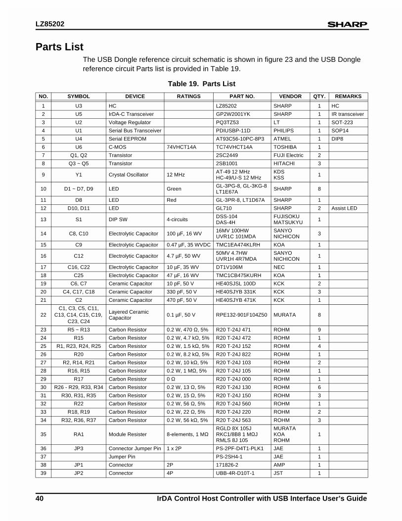
LZ85202
40 IrDA Control Host Controller with USB Interface User’s Guide
Parts ListThe USB Dongle reference circuit schematic is shown in figure 23 and the USB Dongle reference circuit Parts list is provided in Table 19.
Table 19. Parts List
NO. SYMBOL DEVICE RATINGS PART NO. VENDOR QTY. REMARKS
1 U3 HC LZ85202 SHARP 1 HC
2 U5 IrDA-C Transceiver GP2W2001YK SHARP 1 IR transceiver
3 U2 Voltage Regulator PQ3TZ53 LT 1 SOT-223
4 U1 Serial Bus Transceiver PDIUSBP-11D PHILIPS 1 SOP14
5 U4 Serial EEPROM AT93C56-10PC-8P3 ATMEL 1 DIP8
6 U6 C-MOS 74VHCT14A TC74VHCT14A TOSHIBA 1
7 Q1, Q2 Transistor 2SC2449 FUJI Electric 2
8 Q3 ~ Q5 Transistor 2SB1001 HITACHI 3
9 Y1 Crystal Oscillator 12 MHz AT-49 12 MHzHC-49/U-S 12 MHz
KDSKSS 1
10 D1 ~ D7, D9 LED Green GL-3PG-8, GL-3KG-8LT1E67A SHARP 8
11 D8 LED Red GL-3PR-8, LT1D67A SHARP 1
12 D10, D11 LED GL710 SHARP 2 Assist LED
13 S1 DIP SW 4-circuits DSS-104DAS-4H
FUJISOKUMATSUKYU 1
14 C8, C10 Electrolytic Capacitor 100 µF, 16 WV 16MV 100HWUVR1C 101MDA
SANYONICHICON 3
15 C9 Electrolytic Capacitor 0.47 µF, 35 WVDC TMC1EA474KLRH KOA 1
16 C12 Electrolytic Capacitor 4.7 µF, 50 WV 50MV 4.7HWUVR1H 4R7MDA
SANYONICHICON 1
17 C16, C22 Electrolytic Capacitor 10 µF, 35 WV DT1V106M NEC 1
18 C25 Electrolytic Capacitor 47 µF, 16 WV TMC1CB475KURH KOA 1
19 C6, C7 Ceramic Capacitor 10 pF, 50 V HE40SJSL 100D KCK 2
20 C4, C17, C18 Ceramic Capacitor 330 pF, 50 V HE40SJYB 331K KCK 3
21 C2 Ceramic Capacitor 470 pF, 50 V HE40SJYB 471K KCK 1
22C1, C3, C5, C11,
C13, C14, C15, C19, C23, C24
Layered Ceramic Capacitor 0.1 µF, 50 V RPE132-901F104Z50 MURATA 8
23 R5 ~ R13 Carbon Resistor 0.2 W, 470 Ω, 5% R20 T-24J 471 ROHM 9
24 R15 Carbon Resistor 0.2 W, 4.7 kΩ, 5% R20 T-24J 472 ROHM 1
25 R1, R23, R24, R25 Carbon Resistor 0.2 W, 1.5 kΩ, 5% R20 T-24J 152 ROHM 4
26 R20 Carbon Resistor 0.2 W, 8.2 kΩ, 5% R20 T-24J 822 ROHM 1
27 R2, R14, R21 Carbon Resistor 0.2 W, 10 kΩ, 5% R20 T-24J 103 ROHM 2
28 R16, R15 Carbon Resistor 0.2 W, 1 MΩ, 5% R20 T-24J 105 ROHM 1
29 R17 Carbon Resistor 0 Ω R20 T-24J 000 ROHM 1
30 R26 - R29, R33, R34 Carbon Resistor 0.2 W, 13 Ω, 5% R20 T-24J 130 ROHM 6
31 R30, R31, R35 Carbon Resistor 0.2 W, 15 Ω, 5% R20 T-24J 150 ROHM 3
32 R22 Carbon Resistor 0.2 W, 56 Ω, 5% R20 T-24J 560 ROHM 1
33 R18, R19 Carbon Resistor 0.2 W, 22 Ω, 5% R20 T-24J 220 ROHM 2
34 R32, R36, R37 Carbon Resistor 0.2 W, 56 kΩ, 5% R20 T-24J 563 ROHM 3
35 RA1 Module Resister 8-elements, 1 MΩRGLD 8X 10⁵JRKC1/8B8 1 MΩJRMLS 8J 105
MURATAKOAROHM
1
36 JP3 Connector Jumper Pin 1 x 2P PS-2PF-D4T1-PLK1 JAE 1
37 Jumper Pin PS-2SH4-1 JAE 1
38 JP1 Connector 2P 171826-2 AMP 1
39 JP2 Connector 4P UBB-4R-D10T-1 JST 1
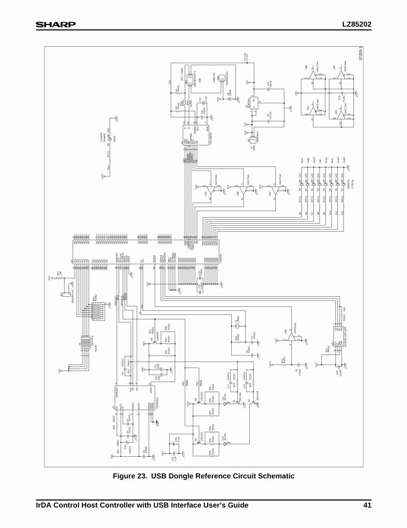
LZ85202
IrDA Control Host Controller with USB Interface User’s Guide 41
Figure 23. USB Dongle Reference Circuit Schematic
PO
WE
RLT
1D67
A
(RE
D)
D8
LED
R13
R47
1J
VC
C
PI0
93
PI1
94
PI2
95
PI3
96
PI4
97
PI5
98
PI6
99
PI7
100
NC
81
NC
82
NC
83
NC
84
NC
85
NC
86
NC
87
NC
88
FE
RE
SE
T 7
9IR
TX
75
IRT
XLP
F 7
4IR
TX
BIA
S 7
7IR
RX
1 9
1F
EC
NT
80
IRR
X2
92
CI
63
CO
64
RE
SE
T 6
0
EE
PC
S 2
9E
EP
CK
28
EE
PD
ATA
27
DB
G 4
0T
ES
T 4
1O
UT
RO
M 4
2O
UT
RA
M 4
3
VD
D 1
4V
DD
25
VD
D 3
1V
DD
32
VD
D 3
9V
DD
61
VD
D 7
3V
DD
78
VD
D 9
0
GN
D 1
GN
D 1
3G
ND
38
GN
D 5
1G
ND
62
GN
D 7
6G
ND
89
NC
52N
C53
NC
54N
C55
NC
56N
C57
NC
58N
C59
NC
2N
C 3
NC
4N
C 5
NC
6N
C 7
NC
8N
C 9
NC
10N
C11
NC
12N
C15
NC
16N
C17
NC
18N
C19
NC
20N
C21
NC
22N
C23
NC
24
NC
26N
C30
NC
33N
C34
NC
35N
C36
NC
37
VM
O48
VP
O49
US
BO
E50
SU
SP
ND
44U
SB
RC
V47
VP
46V
M45
PO
065
PO
166
PO
267
PO
368
PO
469
PO
570
PO
671
PO
772
U3
1 2
JP4
R21
10K
VC
C
HE
AD
ER
2X
1
LZ85
20X
VC
C
VC
C
R22
R56
0J
R20
R82
2F
C4
CH
331J
F0
9
AV
CC
1C
X 4
AG
ND
5
DV
CC
6
DG
ND
7G
ND
A 1
2G
ND
B 1
3
FE
RE
SE
T 3
TX
D10
VO
8
SD
2
LED
A11
U5
GP
2W20
01
0 1 2 3
Hos
tID
1 2 3 4
8 7 6 5
S1
SW
DIP
-4
123
45
67
89
RA
1R
105J
FE
RE
SE
TIR
TX
IRT
XB
IAS
CI
CO
FE
CN
TIR
RX
1
VC
C
Q5
2SB
1001
R33
R13
0JR
34R
130J
R35
R15
0J
R37
R56
3J
VC
C
R23
R15
2JC
1F
104Z
C2
CH
471J
C3
F10
4ZC16
10uF
(T)
Q4
2SB
1001
R28
R13
0JR
29R
130J
R30
R15
0J
VC
C
C24
.1 µ
FC
2547
µF
Q3
2SB
1001
R26
R13
0JR
27R
130J
R31
R15
0JR32
R56
3J
R36
R56
3JV
CC
C13
F10
4ZC
15F
104Z
2 1
8
2 0
11 0
U6A
74H
CT
244
VC
C
VM
O 1
3V
PO
12
OE
2S
US
PE
ND
6R
CV
3V
P 4
VM
5
D+
11
D-
10
SP
EE
D 9
VC
C14
GN
D 7
U1
PD
IUS
BP
11
R2
R10
3J
C11
F10
4Z
VM
OV
PO
US
BO
EB
SU
SP
EN
DU
SB
RC
VV
PV
M
(FG
->
GN
D)
US
B
US
B(+
5V)
R1
R15
2J
C12
4.7u
F
23
14
JP2
UB
B-4
R-D
10T-
1
R18
R22
0J
R19
R22
0J
3.3V
VI
1 2V
O3
5
U2
PQ
3TZ
53
C8
100u
F
1 2JP3
HE
AD
ER
2X
1
TO
3.3
V
VC
C
5V1 2
JP1
HE
AD
ER
2
TP
2
4 1
6
2 0
11 0
U6B
74H
CT
244
VC
C
C6
CH
10J
C7
CH
10J
R16
R10
5JY
112
MH
z
C17
CH
331J
R24
R15
2J
C18
CH
331J
R25
R15
2J
Q1 2S
C24
49
Q2 2S
C24
49
D11
GL7
10D
10G
L710
C5
F10
4Z
R15
R10
5J
812
2 0
11 0
U6D
74H
CT
244
VC
C
VC
C
R5
R47
1J
R6
R47
1J
Num
D1
LED
D9
LED
6 1
4
2 0
11 0
U6C
74H
CT
244
VC
C
GN
D
TP
4V
CC
11
9
2 0
1 91 0
U6E
74H
CT
244
13
7
2 0
1 91 0
U6F
74H
CT
244
VC
C
15
5
2 0
1 91 0
U6G 74
HC
T24
4
17
3
2 0
1 91 0
U6H
74H
CT
244
Cap
s
Scr
oll
Vol
t
Enu
m
Bin
d
Con
f1
Con
f2
(GR
EE
N)
D2
LED
D3
LED
D4
LED
D5
LED
D6
LED
D7
LED
R7
R47
1J
R8
R47
1J
R9
R47
1J
R10
R47
1J
R11
R47
1J
R12
R47
1JR
14R
103J
C14
F10
4Z
CS
1S
K 2
DI
3D
O 4
GN
D 5
OR
G 6
DC
7V
CC
8U
4
AT
93C
56-1
0PC
-8P
3
R17
R00
0J
VC
C
C19
F10
4Z
3725
3-1
LT1E
67A
VC
C
C23
.1 µ
F
C22
10 µ
F
C9
0.47
µF
C10
100
µF

NORTH AMERICA EUROPE ASIA
SHARP Microelectronicsof the Americas5700 NW Pacific Rim Blvd., M/S 20Camas, WA 98607, U.S.A.Phone: (360) 834-2500Telex: 49608472 (SHARPCAM)Facsimile: (360) 834-8903http://www.sharpsma.com
SHARP Electronics (Europe) GmbHMicroelectronics DivisionSonninstraße 320097 Hamburg, GermanyPhone: (49) 40 2376-2286Telex: 2161867 (HEEG D)Facsimile: (49) 40 2376-2232
SHARP CorporationIntegrated Circuits Group2613-1 Ichinomoto-ChoTenri-City, Nara, 632, JapanPhone: (07436) 5-1321Telex: LABOMETA-B J63428Facsimile: (07436) 5-1532
®
![SAM D21 XPRO USB Host MSC Bootloader · SAM D21 XPRO USB Host MSC Bootloader [TRAINING MANUAL] Atmel-42352A-SAM-D21-XPRO-USB-Host-MSC-Bootloader_Training-Manual_022015 4 1 Training](https://static.fdocuments.in/doc/165x107/5f0556927e708231d41278b3/sam-d21-xpro-usb-host-msc-bootloader-sam-d21-xpro-usb-host-msc-bootloader-training.jpg)