Lync Over Aruba WiFi Validated Reference...
69
Lync over Aruba Wi-Fi Validated Reference Design
-
Upload
truongliem -
Category
Documents
-
view
246 -
download
14
Transcript of Lync Over Aruba WiFi Validated Reference...
Lync over Aruba Wi-FiValidated Reference Design
2 | LyncOver ArubaWi-FiValidated Reference Design
Warning and Disclaimer
This guide is designed to provide information about wireless networking, which includes Aruba Network products.Though Aruba uses commercially reasonable efforts to ensure the accuracy of the specifications contained in thisdocument, this guide and the information in it is provided on an “as is” basis. Aruba assumes no liability orresponsibility for any errors or omissions.
ARUBA DISCLAIMS ANY AND ALLOTHER REPRESENTATIONS AND WARRANTIES, WHETHEREXPRESSED, IMPLIED, OR STATUTORY, INCLUDINGWARRANTIES OFMERCHANTABILITY, FITNESSFOR A PARTICULAR PURPOSE, TITLE, NON-INFRINGEMENT, ACCURACY, AND QUIET ENJOYMENT. INNOEVENT SHALL THE AGGREGATE LIABILITY OF ARUBA EXCEED THE AMOUNTS ACTUALLY PAID TOARUBA UNDER ANY APPLICABLEWRITTEN AGREEMENT OR FOR ARUBA PRODUCTS OR SERVICESPURCHASED DIRECTLY FROM ARUBA, WHICHEVER IS LESS.
Aruba Networks reserves the right to change, modify, transfer, or otherwise revise this publication and the productspecifications without notice.

LyncOver ArubaWi-FiValidated Reference Design Contents | 3
Contents
Contents 3
Introduction 7
Lync Overview 8
Lync Security 8
Lync OverWLAN 8
Supported Client Platforms 9
Lync Architecture 10
Lync Topology 10
Lync Front End Pool 10
Lync SDN Manager 10
Active Directory 11
Lync Edge Server 11
Reverse Proxy 11
QoE Server 11
Lync Network Characteristics 12
Upstream QoS 12
Client roam time 12
Aruba WLAN and Lync 13
Aruba Controller-BasedWLAN and Lync 13
Heuristics Method 13
Lync SDN API Method 14
Deployment Considerations with Heuristics and SDN API 16
IAPs and Lync 16
Aruba Infrastructure Configuration Guidelines 18
AP Selection and Placement Recommendations 18
Capacity Based RF Design 18
AP Placement Recommendations 18
Carpeted Office Space 19
High Ceiling and Long Corridor Spaces 19
Retail Stores 19
Conference Rooms and Large Auditoriums 19
4 | Contents LyncOver ArubaWi-FiValidated Reference Design
AP Selection Recommendations 20
802.11ac AP Considerations 20
RF Considerations 20
Controller Settings 20
IAP Configuration Recommendations 21
Remote AP Configuration Recommendations 21
Authentication and Encryption Guidelines 22
High Availability Guidelines 22
Network PerformanceGuidelines 22
Network Topology Considerations 23
Campus Deployment Considerations 23
Lync SDN Message Flow in Controller Deployment 24
Distributed Enterprise Deployment Considerations 25
Controller Based Solution at Remote Sites 25
IAP Based Remote Deployment 26
RAP Based Deployment 27
Multi-site Lync Architecture 27
Multi-site Deployment with SDN API 27
Multi-site Deployment with SDN API and Heuristics 28
Guest and BYOD Access Topology 28
VLAN Based BYOD Latency Challenge 29
Optimal BYOD Lync Traffic Engineering 29
ForwardingMode Considerations 30
QoS 31
Classifying Unmarked Traffic 31
Incoming Traffic is Marked 31
Remarking Traffic to a Different Class 32
WMM andQoS 32
QoS Segments 33
QoS Considerations 33
QoS Flow 35
WMMOnlyMode 35
HeuristicsMode 35
SDN APIMode 36
Wired toWireless 36
Wireless toWired 37
DSCP Considerations 37
DSCP-EF 46 and WMM 39
Lync on VDI 40
Scalability Considerations 41
Call Scalability Per AP Per Radio 41
SDN API Scalability 41
Aruba Solution for Lync E911 42
Troubleshooting 43
SDN Integration Troubleshooting 43
Controller Troubleshooting 43
AP Troubleshooting 45
RF Troubleshooting 46
Wired Network Troubleshooting 46
Lync Troubleshooting Using UCC Dashboard and CLI commands 46
CLI Commands for Lync Troubleshooting 49
UCC Troubleshooting on AirWave 8.0 50
Appendix 52
Lync SDN API Installation and Configuration Guidelines 52
Lync Server Side Configuration 52
Lync Dialog Listener Configuration 52
LSM Configuration 53
Configuring Aruba Controller for SDN API Interoperability 55
CommonConfiguration for ArubaOS 6.3 and 6.4 55
ArubaOS 6.4 specific Enhancements 64
Aruba Controller Configuration for AirWave 8.0 UCC Integration 65
Aruba Controller Lync Heuristics Configuration 65
Configuring the ArubaMobility Controller to Detect Lync Traffic for Lync 2010/2013 65
Configuring the ArubaMobility Controller to Detect Lync Traffic 66
Verifying Operation of Heuristics Detection of Lync Traffic 66
Default DSCP-WMMmapping for Heuristics 67
What’s New in ArubaOS 6.4 67
Enable SDN API and Lync Heuristics Simultaneously 67
Dynamic Opening of Ports for Lync Voice/Video Traffic 67
Caveats for ArubaOS 6.4 67
Aruba Instant Lync Heuristics Configuration 67
LyncOver ArubaWi-FiValidated Reference Design Contents | 5
6 | Contents LyncOver ArubaWi-FiValidated Reference Design
Creating QoS Policy on aWindows Client 68
Managing QoS from Lync Server throughGroup Edit Policy 69
Network Bandwidth Requirements for Different Codecs 69
LyncOver ArubaWi-FiValidated Reference Design Introduction | 7
Chapter 3Introduction
Enterprises and institutions around the world aremoving away from the wired phone technology and towards the allwireless workplace. Wi-Fi connected smart phones and soft phones that support Microsoft Lync unifiedcommunications enhance productivity and collaboration while delivering uninterruptedmobility to users.
Listed below are the steps to deploy a Lync solution:
1. Scope the requirements.
2. Conduct a Lync mobility readiness assessment to determine if the network infrastructure is suitable. If needed,run a pilot.
3. Use only Lync qualified equipment in the actual roll out.
4. To ensure good end user experience, do not apply the appropriate tags and quality of servicemechanisms if youare unable to differentiate between Instant Messaging (IM) and voice. As Lync’s end-to-end encryption is ideal forsecurity but it breaks traditional quality of servicemechanisms.
5. Ensure the best possible insights into system performance for quick root cause analysis.
To resolve a problem quickly, you need to open a window in the system from the Lync client to the Lync server. If you areunable to open the window, you will be unable to analyze where the problem occurs resulting in wastage of resourceand delay in the root cause analysis.
The Lync Software-Defined Networking (SDN) Application Program Interface (API) was developed tomake callrelated data, Lync statistics, and call history information available through a single API. Aruba Lync qualified SDNAPI can access the Lync server and create comprehensive picture of applications, users, devices, and theWi-Fi andLAN network infrastructure. The Lync SDN API and Aruba’s network and device related data provides an end-to-endview into real-time calls, identifies fault locations and device issues, and allows you to run root-cause diagnosticsfrom client to server. These features enable you tomove away from wired IP phones as you can deliver full Lyncuser mobility, enhance productivity, and workplace collaboration, resulting in cost savings from rightsizing yourwired infrastructure.
This document details all aspects of Wi-Fi network engineering and design for an enterprise-widemobile Lyncdeployment that includes:
l AP placement
l RF design
l Network topology considerations
l WLAN configuration
l Quality of Service (QoS)
l Lync visibility
l Troubleshooting
It also discusses Lync design considerations when deploying both controller and virtual controller based ArubaWi-Fi. Design considerations encompass the use of:
l Lync for voice
l HD video
l Conferencing
l Desktop sharing
l File transfers
8 | Introduction LyncOver ArubaWi-FiValidated Reference Design
This document assumes that you are using a fully functional and testedMicrosoft Lync deployment and have anadvanced understanding of network topology andWLAN deployments.
Lync OverviewMicrosoft Lync is a real time communication platform based on theMicrosoft Lync server andOffice productivitysuite. Lync is commonly deployed in enterprises that useMicrosoft Active Directory and Exchange e-mail, thoughhosted and cloud-based Lync deployments are very common.
Listed below are the five primary Lync features:
l Voice calling – peer to peer or to/from the PSTN through Session Border Controller (SBC)
l Video conferencing – HD quality video
l Desktop sharing – screen share and application collaboration
l File sharing – securely transfer files peer-to-peer
l Conferencing – video, voice, content sharing, file share, and dial-in-access
Lync SecurityLync communication channels are encrypted. Server-to-server data exchange is also encrypted and authenticatedusingMutual Transport Layer Security (MTLS). Each server is issued a server certificate by a trusted CertificateAuthority (CA), which is then used for authentication and to exchange a symmetric key to encrypt the networksession.
Lync uses Session Initiation Protocol (SIP) as the signaling protocol, which is encrypted using Transport LayerSecurity (TLS). Since Lync leverages a secured SIP channel, Lync IM traffic also benefits from the same TLSencryption.
Application sharing uses Remote Desktop Protocol (RDP). This TCP traffic uses TLS as the underlying transport,and authentication is established over a secure SIP channel.
Web conferencing traffic uses Persistent SharedObject Model (PSOM), which uses TLS as the underlyingtransport, and authentication is established over a secured SIP channel.
To prevent eavesdropping and packet rejection, Secure Real-time Transport Protocol (SRTP) uses 128-bit AESstream encryption to protect audio and video (A/V) traffic traveling to and from the Lync server. The Lync serverestablishes amedia path that can traverse firewalls and Network Address Translations (NATs) before allowing A/Vtraffic to flow between two endpoints.
Lync Over WLANThe three core design components of a Lync ready WLAN includes access to airtime, QoS, and visibility. Delay in ordisruptions to the flow of Lync traffic can cause quality issues. Addressing each of the core design components in asystematic approach can helpminimize latency and improve user experience.
Lync is an application that typically runs on a general-purpose device, so it is typically not feasible to dedicate CPUtime exclusively to Lync applications. Rather the objective is to achieve coexistence of Lync and other applicationswhile being able to prioritize Lync traffic over the air to minimize latency and improveQoS.
Best case scenarios expect that you achieve the following goals as measured peer-to-peer (local and remote), peer-to-gateway (SBC), peer-to-conference bridge:
l Round trip delay < 100ms
l Jitter < 10ms
l Packet loss <5%
The above parameters should bemeasured with load and typical background traffic ≥ 100Mbps.
Supported Client PlatformsLync 2013 clients are available for themost common computing and telecommunication platforms, including:
l Desktop OS -Windows (XP, Vista, 7, 8), OSX
l Mobile - iOS, Android, Windows Mobile, Windows 8 RT
l Lync room systems
l Dedicated Lync endpoints - Polycom, Snom, and so on
l Embedded applications using the Lync API
LyncOver ArubaWi-FiValidated Reference Design Introduction | 9

LyncOver ArubaWi-FiValidated Reference Design LyncArchitecture | 10
Chapter 4Lync Architecture
Lync TopologyLync clients are assigned to a cluster of front end servers, called Lync front end pool. Large Lync deployments havemany front end pools deployed to serve a wide geographic area. In a global deployment, Lync clients will registerwith their home front end servers despite their proximity to a closer front end server and this information is veryuseful while troubleshooting Lync issues.
Failure to understand the distribution of Lync users to Lync front end servers in relation to the configured SDN API resultsin SDN API messages missed or not sent at all.
Lync is designed to traverse the public Internet without any additional components like VPNs or specialized ports.The Lync client detects the public Internet that is outside the corporate network using a DNS query. When usingoutside network, Lync can traverse the corporate border through the Lync Edge server.
The following figure shows different components of Lync network.
Figure 1 Lync Network Components
Lync Front End PoolThe front end Lync server pool performs call processing and can be pooled together with other front end servers tocreate a fault tolerant front end pool. Front end servers can also perform bridging or conferencing functions in theabsence of a dedicated bridge. Clients connect directly to a Lync front end server to make or setup calls andcommunicate with other users. The front end server communicates with Aruba infrastructure using Lync SDN APIDialog Listener and Lync SDN Manager (LSM).
Lync SDN ManagerThe LSM is a component of the SDN API architecture that acts as a collector and forwarding agent for SDN APImessages. The LSM receives Lync SDN messages frommultiple Lync front end servers and sends thesemessages to ArubaMobility Controllers. The LSM can be installed on the Lync server for small scale deploymentunder 100 subscribers. For deployments with more than 100 Lync users, the LSM should be installed on a separateWindows 2008/2012 server.
11 | LyncArchitecture LyncOver ArubaWi-FiValidated Reference Design
Active DirectoryLync is integrated with Microsoft Active Directory. The Active Directory (AD) is the repository for Lync usercredentials and also stores the Lync topology in the directory schema. Lync users are created in the AD and thenenabled in the Lync server manager control panel.
Lync Edge ServerThe Lync Edge server enables external users such as authenticated and anonymous remote users, federatedpartners, mobile clients, and users of public IM services to communicate with other users inside the Lync domain.The Lync Edge server uses port 443 to communicate to the front end pool.
Reverse ProxyReverse proxy is used for external discovery of a Lync front end pool assignment. Reverse proxy is required forexternal clients to access the Lync server web services that are on the internal network.
QoE ServerTheQoE server provides end-to-end call quality metrics for Lync calls. TheQoE server is amandatory part of theLync SDN API integration for Aruba to get visibility to end-to-end call quality metrics. Lync clients collect data duringa call and send the data to the front end server, which forwards it to the QoE server that includes aMicrosoft SQLserver database. TheQoE server is responsible for calculating call quality metrics such as MOS (MeanOpinionScore), packet loss, jitter, and call delay. MOS represents the end-to-end call quality for Lync voice calls whichranges from 0 (worst) to 5 (toll quality).
Lync call classification and prioritization works without the QoE Server.
The SDN API plug-in on the Lync front end server will only send a MOS score if an active QoE server is installed.

LyncOver ArubaWi-FiValidated Reference Design LyncNetworkCharacteristics | 12
Chapter 5Lync Network Characteristics
Lync follows a SIP registration and call control ladder model. The Lync client uses a DNS service discovery model todetermine how it will sign into Lync. When the client signs into Lync, it registers with a Lync front end server, or if it isan external network the client registers with an edge server. When a call is made, the Lync client communicates tothe front end or edge server to setup the call over Transmission Control Protocol (TCP). Once the call is setup, RealTime Transport Protocol (RTP) data traffic flows between the clients or media gateways directly using UserDatagram Protocol (UDP).
Listed below are the ports used for Lync communications:
• TCP 53 - Lync DNS query
• TCP 5061 – Lync clients inside a corporate network
• TCP 5063 - Used for incoming SIP requests for audio/video conferencing
• TCP 443 – Used by Lync clients outside a corporate network or all online Lync clients
• UDP 3478 – Used for Session Traversal Utilities for NAT (STUN)messages. Lync clients initiate STUNconnectivity check prior to media transmission. Once STUN connectivity check is succeeded, media transmissionoccurs.
• UDP 50000 – 65000 – Typical port range used for RTP, can be set to a specific port range on the Lync server.
Upstream QoSOnly Windows clients (Vista/Win7/8) are capable of performing upstream tagging of Lync RTP packets with QoSmarkings. Enabling upstream tagging provides significant improvement on Lync quality, to enable upstream tagging,configure a group policy. For detailed instructions, seeManaging QoS from Lync Server throughGroup Edit Policy.
Refer to the client QoS section for caveats related to upstream tagging.
Client roam timeWhen Lync wireless clients roam from one access points to another, they might face connectivity issues. A roaminterval >200ms results in Lync voice quality issues and causes Lync clients to disconnect and re-register with thefront end server. Tominimize the roaming interval, refer to configuration best practices.
LyncOver ArubaWi-FiValidated Reference Design ArubaWLAN and Lync | 13
Chapter 6Aruba WLAN and Lync
Aruba controller and Instant AP (IAP) based architectures have built in Application Layer Gateways (ALG) thatdetects and classifies different types of Lync applications. Both controller and IAP infrastructures dynamicallyprioritize high priority Lync traffic such as voice and video over other Lync data traffic.
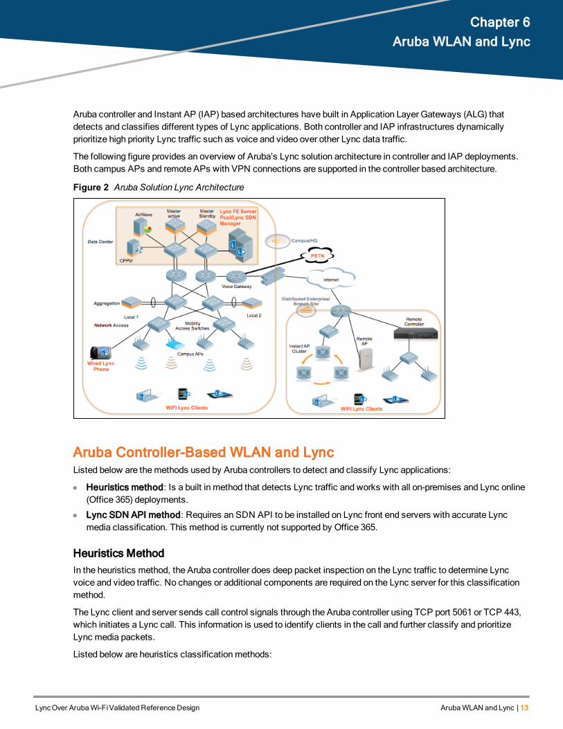
The following figure provides an overview of Aruba’s Lync solution architecture in controller and IAP deployments.Both campus APs and remote APs with VPN connections are supported in the controller based architecture.
Figure 2 Aruba Solution Lync Architecture
Aruba Controller-Based WLAN and LyncListed below are themethods used by Aruba controllers to detect and classify Lync applications:
l Heuristics method: Is a built in method that detects Lync traffic and works with all on-premises and Lync online(Office 365) deployments.
l Lync SDN API method: Requires an SDN API to be installed on Lync front end servers with accurate Lyncmedia classification. This method is currently not supported by Office 365.
Heuristics MethodIn the heuristics method, the Aruba controller does deep packet inspection on the Lync traffic to determine Lyncvoice and video traffic. No changes or additional components are required on the Lync server for this classificationmethod.
The Lync client and server sends call control signals through the Aruba controller using TCP port 5061 or TCP 443,which initiates a Lync call. This information is used to identify clients in the call and further classify and prioritizeLync media packets.
Listed below are heuristics classificationmethods:

14 | ArubaWLAN and Lync LyncOver ArubaWi-FiValidated Reference Design
l An Access Control List (ACL) is defined on the controller to listen on port TCP 5061 and 5063. The classify mediaoption in the ACL is enabled and is mapped to a user role.
l Once Lync voice/video calls are established, Lync classify media ACL is triggered and Lync clients aremarkedas media capable clients.
l Any subsequent User Datagram Protocol (UDP) dataflow with source/destination port > 1023 from/to mediacapable users go through Lync media Deep Packet Inspection (DPI).
l If an RTP session is based on DPI, the payload type in the RTP header is used to determine if it is a voice orvideo session.
l Once themedia type is determined, the Type of Service (TOS) bits are set on the session. TOS mapping for themedia type is configured in SSID profile.
For more details on Lync heuristics-based configuration, see Aruba Controller Lync Heuristics Configuration on page65.
Lync SDN API MethodLync SDN API can be installed on a Lync 2010 or Lync 2013 server. Lync SDN API provides an interface throughwhich the Aruba controller can access Lync network diagnostic information for voice and video calls, desktopsharing, and file transfer. The Aruba controller uses this data to prioritize Lync traffic and provide information on theusage of Lync applications on the network. The Lync server communicates with the controller through XMLmessages over HTTP or HTTPS.
Listed below are the Lync SDN API 2.0 components:
l Lync Dialog Listener (LDL) installed on the Lync front end server.
l Lync SDN Manager (LSM) installed on aWindows 2008/2012 server.
Lync server SDN API should be obtained directly fromMicrosoft. For more information on LDL and LSM installationrequirements, see the installation guide.
It is critical to review the installation instructions to ensure that you meet Microsoft specific requirements beforeproceeding with the SDN API installation.
The following figure displays the SDN API message flow.
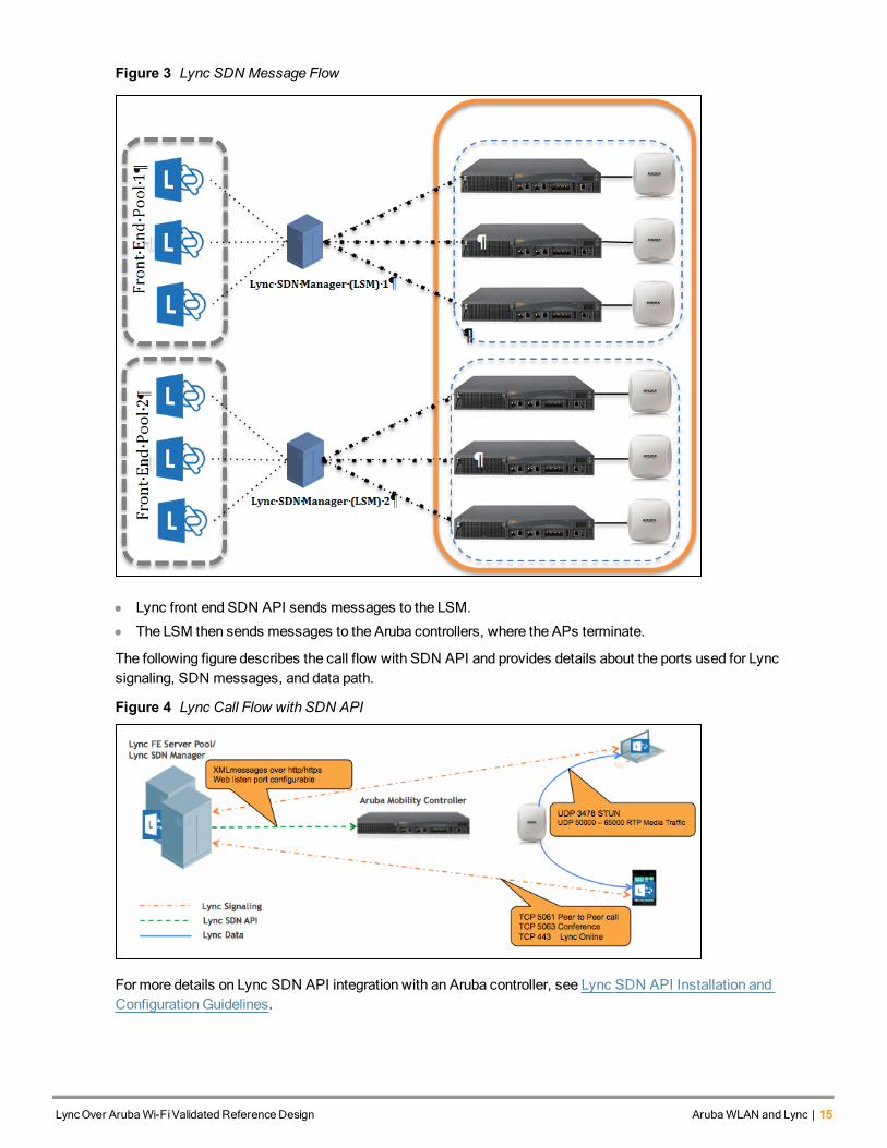
Figure 3 Lync SDN Message Flow
l Lync front end SDN API sends messages to the LSM.
l The LSM then sends messages to the Aruba controllers, where the APs terminate.
The following figure describes the call flow with SDN API and provides details about the ports used for Lyncsignaling, SDN messages, and data path.
Figure 4 Lync Call Flow with SDN API
Formore details on Lync SDN API integration with an Aruba controller, see Lync SDN API Installation andConfiguration Guidelines.
LyncOver ArubaWi-FiValidated Reference Design ArubaWLAN and Lync | 15
16 | ArubaWLAN and Lync LyncOver ArubaWi-FiValidated Reference Design
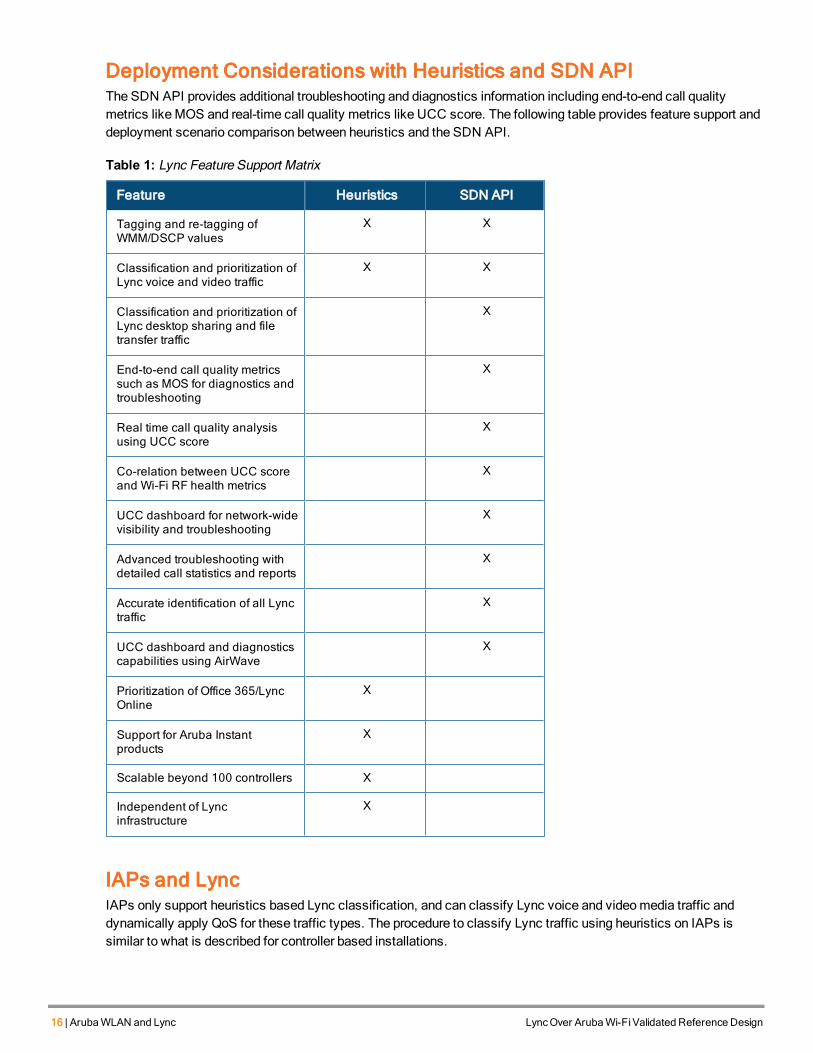
Deployment Considerations with Heuristics and SDN APIThe SDN API provides additional troubleshooting and diagnostics information including end-to-end call qualitymetrics likeMOS and real-time call quality metrics like UCC score. The following table provides feature support anddeployment scenario comparison between heuristics and the SDN API.
Feature Heuristics SDN API
Tagging and re-tagging ofWMM/DSCP values
X X
Classification and prioritization ofLync voice and video traffic
X X
Classification and prioritization ofLync desktop sharing and filetransfer traffic
X
End-to-end call quality metricssuch as MOS for diagnostics andtroubleshooting
X
Real time call quality analysisusing UCC score
X
Co-relation between UCC scoreand Wi-Fi RF health metrics
X
UCC dashboard for network-widevisibility and troubleshooting
X
Advanced troubleshooting withdetailed call statistics and reports
X
Accurate identification of all Lynctraffic
X
UCC dashboard and diagnosticscapabilities using AirWave
X
Prioritization of Office 365/LyncOnline
X
Support for Aruba Instantproducts
X
Scalable beyond 100 controllers X
Independent of Lyncinfrastructure
X
Table 1: Lync Feature Support Matrix
IAPs and LyncIAPs only support heuristics based Lync classification, and can classify Lync voice and videomedia traffic anddynamically apply QoS for these traffic types. The procedure to classify Lync traffic using heuristics on IAPs issimilar to what is described for controller based installations.

Formore information on heuristics based configuration on IAPs, see Aruba Instant Lync Heuristics Configuration onpage 67.
LyncOver ArubaWi-FiValidated Reference Design ArubaWLAN and Lync | 17

LyncOver ArubaWi-FiValidated Reference Design Aruba Infrastructure Configuration Guidelines | 18
Chapter 7Aruba Infrastructure Configuration Guidelines
Pervasive RF coverage, optimum RF signal level, end-to-endQoS are key requirements of a Lync ready network.Sub optimal WLAN designs degrade network performance and result in poor Lync call quality. The right WLANdesign ensures that Lync clients are reliably and continuously communicating with Aruba APs and IAPs. Thissection details RF considerations, including AP selection and placement, andQoS considerations required for Lyncdeployments. In this chapter APs and IAPs will be used interchangeably.
AP Selection and Placement RecommendationsThis section provides details on the considerations and placement of APs for optimum performance.
Capacity Based RF DesignCapacity based networks rely onmore closely spaced APs, operating at lower TX power, to deliver low-latency, highsignal strength, and high bandwidthWi-Fi to densely packed clients. By restricting the cell size this design enablesclients within each cell to associate at higher PHY rates and obtain better performance. In this design the objective isto use the least number of APs, typically operating at the highest TX power, to cover the largest area at the expenseof performance, latency, and client density.
The following example provides a comparison between capacity and coverage based designs in a 802.11nWLANdeployment. In the capacity based design, the clients achieve 216.7Mbps data rate whereas in the coverage baseddesign, clients get 7.2Mbps data rate at the cell edge.
A capacity based network design is required to achieve optimal network performance in an enterprise Lync WLANnetwork.
Figure 5 Coverage vs. Capacity-BasedWLAN Design
AP Placement RecommendationsThis section covers AP placement recommendations for various deployment environments. AP placement isimportant to ensure 100% pervasive coverage. With Lync 2013 all major mobile platforms can now act as Lyncclients, thus increasing themobility of Lync users, which requires wider coverage to accommodatemobile users.This includes, office space, conference rooms, lobbies, end of hallways, stairwells, elevators, bathrooms,mechanical rooms, cafeterias, and parking garages.
19 | Aruba Infrastructure Configuration Guidelines LyncOver ArubaWi-FiValidated Reference Design
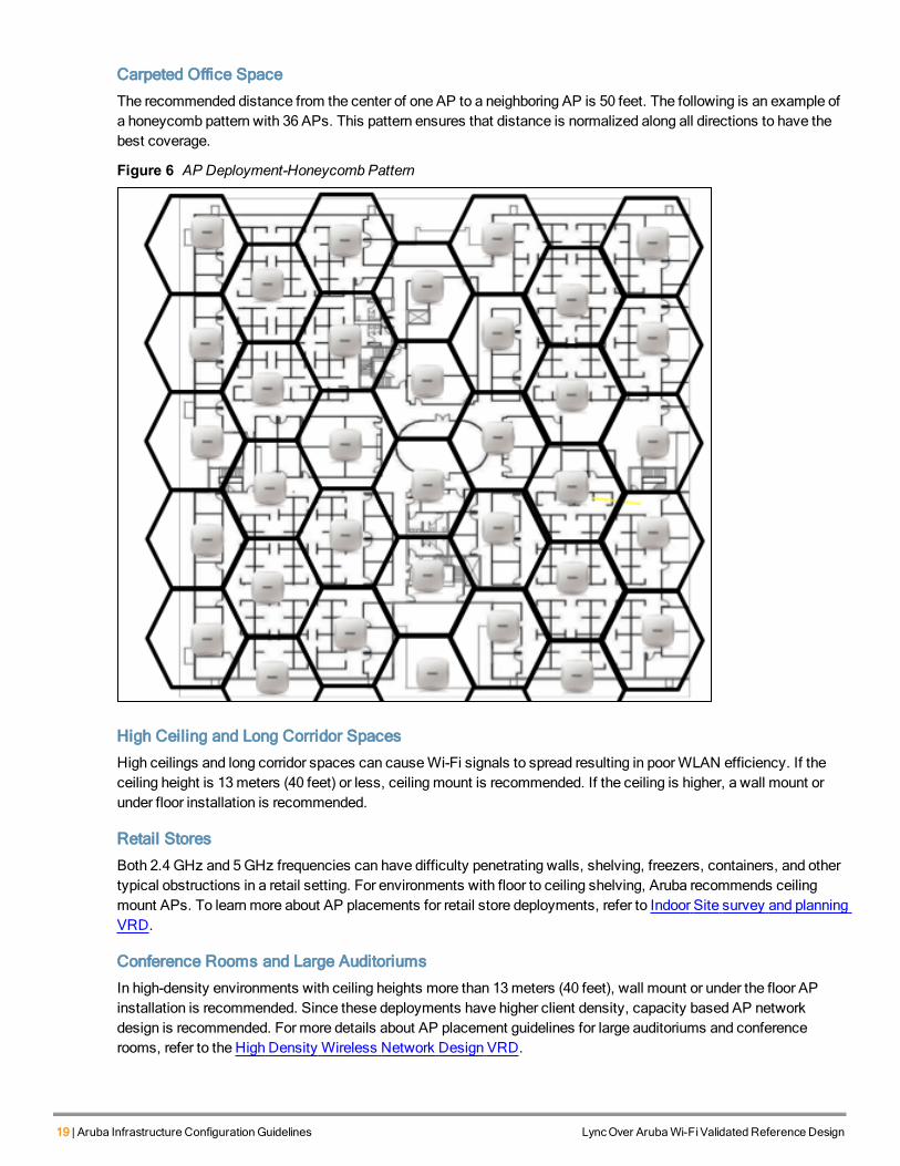
Carpeted Office Space
The recommended distance from the center of one AP to a neighboring AP is 50 feet. The following is an example ofa honeycomb pattern with 36 APs. This pattern ensures that distance is normalized along all directions to have thebest coverage.
Figure 6 AP Deployment-Honeycomb Pattern
High Ceiling and Long Corridor Spaces
High ceilings and long corridor spaces can causeWi-Fi signals to spread resulting in poorWLAN efficiency. If theceiling height is 13meters (40 feet) or less, ceilingmount is recommended. If the ceiling is higher, a wall mount orunder floor installation is recommended.
Retail Stores
Both 2.4 GHz and 5GHz frequencies can have difficulty penetrating walls, shelving, freezers, containers, and othertypical obstructions in a retail setting. For environments with floor to ceiling shelving, Aruba recommends ceilingmount APs. To learnmore about AP placements for retail store deployments, refer to Indoor Site survey and planningVRD.
Conference Rooms and Large Auditoriums
In high-density environments with ceiling heights more than 13meters (40 feet), wall mount or under the floor APinstallation is recommended. Since these deployments have higher client density, capacity based AP networkdesign is recommended. For more details about AP placement guidelines for large auditoriums and conferencerooms, refer to the High Density Wireless Network Design VRD.
AP Selection Recommendations
802.11ac AP Considerations
802.11ac is a high speed and performance next-generationWi-Fi that is rolled out in a wide variety of client devices.802.11ac is ideal for the high bandwidth requirements of clients running unified communications. Aruba recommends200 Series indoor and outdoor access points that are 802.11ac based, for high performance applications.
RF ConsiderationsThe following recommendations should be followed to ensure proper device operation for a high density Lyncdeployment:
l Power Settings
n Transmit power values are 3,6,9,12,15, 18, 21, 24, 27, 30, 33, 127 dbm. Consistent power level results inhigher data rates. Minimum andmaximum AP transmit power difference should not bemore than two stepsapart. For example, if theminimum transmit power is 9 dbm then themaximum transmit power should notexceed 15 dbm.
n AP power setting should use low tomoderate power. For example, in a high density AP deployment set,minimum/maximum power should be 9 -12 dbm for 2.4 GHz and 12 -18 dbm for 5 GHz.
l Disable lower transmit data rates
n If there are no 11b clients in the network, disable lower rates 1 - 11Mbps.
l Set supported beacon rate tomore than 12Mbps
n Beacons that are transmitted at the lowest basic rate, such as 1Mbps, can consume a considerable amountof air time. Set beacons rates higher than 12Mbps to avoid unnecessarily consuming bandwidth.
l Minimum RF signal (RSSI) levels of -65 dbm in 2.4 and 5GHz
l Minimum signal to noise ratio (SNR) of 25 dB
n Higher signal level and high SNR are the indicators of superior RF environment and will improve clienttransmission rates.
l Cell size reduction (CSR): Reducing the cell size reduces the AP receive sensitivity, that is it shrinks the rangeof a client by reducing the Rx sensitivity of the AP. By default CSR is disabled (0 dB). CSR can be carefully setonly after consultation with an experienced engineer.
l Local Probe Request Threshold: The default value of Local Probe Request Threshold parameter is 0 and shouldbe adjusted only by the engineer after a careful analysis. This value is recommended not to be higher than 10.
l Mitigate interference sources, such as microwave ovens, distributed antenna systems, and game consoles
l Use both 2.4 GHz and 5GHz bands
l Use 20MHz channel bandwidth on 2.4 GHz
l 40MHz or less channel bandwidth on 5GHz
n It is recommended that high density deployments use 40MHz or less channel bandwidth to reduce adjacentand co-channel interference. Using 80MHz channel bandwidth in high density AP deployment may result inadjacent or co-channel interference.
Controller Settingsl Broadcast Filter ARP
n Is enabled on the virtual AP profile and all broadcast ARP requests are converted to unicast and sent directlyto the client instead of flooding the network with broadcast ARP packets. Sending broadcast packets athigher unicast data rates improves transmission.
l SSID profile
n Set maximum retries to 8 to limit the re-transmission of packets to a total of 8 attempts.
LyncOver ArubaWi-FiValidated Reference Design Aruba Infrastructure Configuration Guidelines | 20
21 | Aruba Infrastructure Configuration Guidelines LyncOver ArubaWi-FiValidated Reference Design
n Configure QoS settings (DSCP-WMMmapping on the SSID profile) to match QoS settings on the wirednetwork and any upstream QoS settings on the client. This ensures that the sameDSCP values are usedthroughout the wireless and wired network for Lync voice/video traffic.
l ARM profile
n Enable voice/video aware scan to prevent APs from conducting off channel scans during a Lync voice orvideo call.
n Enable client match to provide dynamic spectrum load balancing and dynamic band steering. Client matchcontinuously scans the wireless environment and steers clients to the best available AP. This helps addresssticky clients that remain associated with a non-optimal AP, often a distant one, because the client driverdoes not roam correctly.
l Enable Opportunistic Key Caching (OKC) for 802.1x authentication in the 802.1x profile to assist client roaming.OKC reduces the number of frames sent during authentication and is supported only onWindows devices and afew Android devices, but is not supported on Apple OSX or iOS devices.
l Enable validate pmkid so that the controller looks for PMKID in association or re- association requests from theclient, indicating that the client supports OKC or PMK Caching. This configuration is essential if there are devicesthat do not support OKC, such as Apple OSX or iOS devices. If this option is not enabled, 802.1x authenticationis in initiated. Apple OSX and iOS devices do support PMK caching.
l Enable EAPOL rate optimization to ensure that APs send EAPOL frames at the lowest possible rates, therebyavoiding authentication delay due to packet retransmission.
OKC is only supported onWindows devices and a few Android devices. For Apple OSX or iOS devices where OKCis not supported, use PMK Caching or 802.11r.
IAP Configuration RecommendationsListed below are RF best practices for IAPs. For a detailed explanation of these parameters refer to the controller RFConsiderations on page 20 section.
l 100% coverage in all areas of Lync is in use
l Capacity based RF network design
l Minimum RF signal (RSSI) levels of 65 dBm
l Minimum SNR of 25 dB
l Enable Client Match in the ARM configuration
l Broadcast Filter ARP enabled
l Local probe request threshold should be adjusted only by the engineer after a careful analysis. This value isrecommended not to be higher than 10.
l Traffic shaping ensures that voice and video packets are processed and only background and best effort traffic ismodified to preserve Lync quality. These settings can bemodified inWLAN settings under Advanced options.Adjust the voice and video percentages based on the expected voice/video traffic in your environment.
Remote AP Configuration RecommendationsRAPs are intended for use at remote sites and to setup an IPsec VPN tunnel for secure communications. RAPssupport heuristics based Lync classification in Tunnel and D-Tunnel modes only. SDN API based Lyncclassification is supported in Split Tunnel, Tunnel, and D-Tunnel modes. Select and configure the appropriateforwardingmode for your application.
Authentication and Encryption Guidelines
Ensure that latency and jitter intervals are minimum during authentication/re-authentication process.
Tomaximize security, 802.1x with AES is the preferred authentication/encryptionmethod overWPA2-PSK (pre-shared keys). For 802.1x based authentication, ensure that OKC or PMK caching is enabled for fasterauthentication.
EAP-TLS certificate based authentication is preferred over PEAP authentication as it reduces delays introduced withpassword authentication through Active Directory. For networks in which the Certificate Authority is separate fromActive Directory, the EAP-TLS authentication request is processed on the Clear Pass server, for example, whenAruba ClearPass Policy Manager (CPPM) is used. PEAP transactions require CPPM to send the passwordauthentication request to the Active Directory server which delays the authentication process.
High Availability GuidelinesIn amulti-controller based architecture, ensure that AP fast failover is enabled for hitless failover in case of acontroller failure. With AP fast failover, access points will not go down but Lync clients will be de- authenticated andre-associated. For example, if there are two controllers in the network and the Lync clients are associated to an APon controller-1 and if controller-1 fails, Lync clients are re-authenticated to controller-2 and Lync calls in process areinitiated again and new Lync session entries are created based on call re-initiation.
By default IAP virtual controllers support hitless failover.
Network Performance GuidelinesEnsure your deployment meets the following conditions to achieve optimum network performance:
l Ensure that the sameQoS tagging is configured and validated across all wired switches/routers and in end-to-endwireless infrastructure. Ensure that APs are included in QoS trust to enable upstreammarkings.
l Round trip delay < 100ms between clients.
l Jitter < 10ms.
l Packet loss< 5%.
l Configure QoS trust on all voice ports to honor the QoS markings.
LyncOver ArubaWi-FiValidated Reference Design Aruba Infrastructure Configuration Guidelines | 22
LyncOver ArubaWi-FiValidated Reference Design NetworkTopologyConsiderations | 23
Chapter 8Network Topology Considerations
This section describes the Lync deployment design considerations for controller based campus deployments,branch office deployments, andmulti-site Lync deployments. The design consideration explains how a Lync networkis tailored for each scenario.
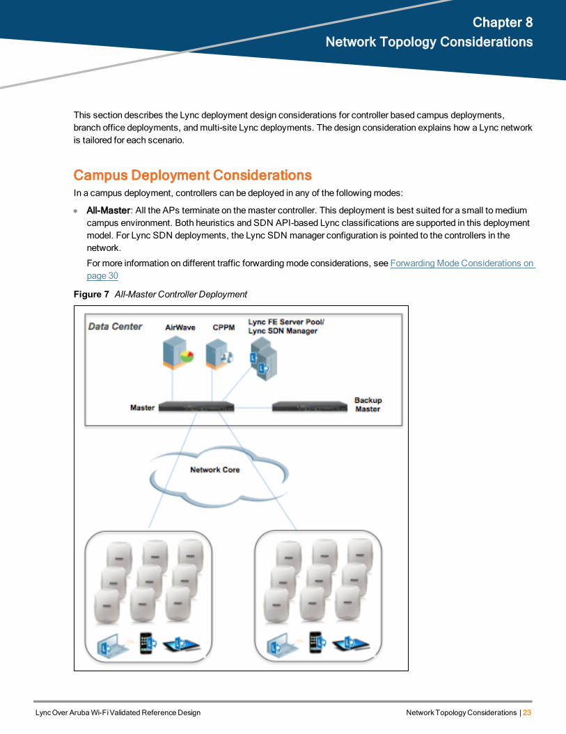
Campus Deployment ConsiderationsIn a campus deployment, controllers can be deployed in any of the followingmodes:
l All-Master: All the APs terminate on themaster controller. This deployment is best suited for a small to mediumcampus environment. Both heuristics and SDN API-based Lync classifications are supported in this deploymentmodel. For Lync SDN deployments, the Lync SDN manager configuration is pointed to the controllers in thenetwork.
For more information on different traffic forwardingmode considerations, see ForwardingMode Considerations onpage 30
Figure 7 All-Master Controller Deployment
24 | NetworkTopologyConsiderations LyncOver ArubaWi-FiValidated Reference Design
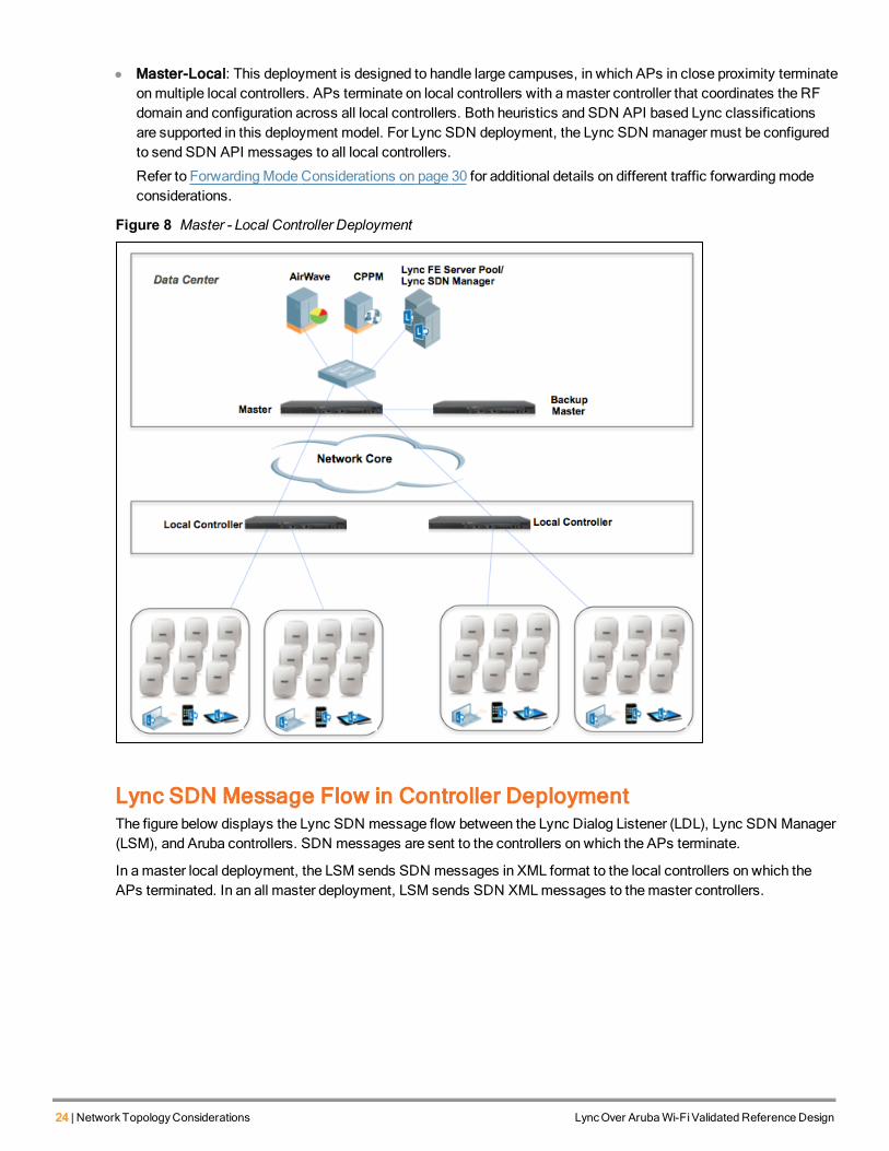
l Master-Local: This deployment is designed to handle large campuses, in which APs in close proximity terminateonmultiple local controllers. APs terminate on local controllers with amaster controller that coordinates the RFdomain and configuration across all local controllers. Both heuristics and SDN API based Lync classificationsare supported in this deployment model. For Lync SDN deployment, the Lync SDN manager must be configuredto send SDN API messages to all local controllers.
Refer to ForwardingMode Considerations on page 30 for additional details on different traffic forwardingmodeconsiderations.
Figure 8 Master - Local Controller Deployment
Lync SDN Message Flow in Controller DeploymentThe figure below displays the Lync SDN message flow between the Lync Dialog Listener (LDL), Lync SDN Manager(LSM), and Aruba controllers. SDN messages are sent to the controllers on which the APs terminate.
In amaster local deployment, the LSM sends SDN messages in XML format to the local controllers on which theAPs terminated. In an all master deployment, LSM sends SDN XMLmessages to themaster controllers.
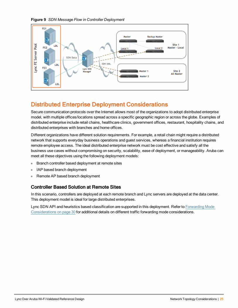
Figure 9 SDN Message Flow in Controller Deployment
Distributed Enterprise Deployment ConsiderationsSecure communication protocols over the Internet allows most of the organizations to adopt distributed enterprisemodel, with multiple offices/locations spread across a specific geographic region or across the globe. Examples ofdistributed enterprise include retail chains, healthcare clinics, government offices, restaurant, hospitality chains, anddistributed enterprises with branches and home offices.
Different organizations have different solution requirements. For example, a retail chain might require a distributednetwork that supports everyday business operations and guest services, whereas a financial institution requiresremote employee access. The ideal distributed enterprise network must be cost effective and satisfy all thebusiness use cases without compromising on security, scalability, ease of deployment, or manageability. Aruba canmeet all these objectives using the following deployment models:
l Branch controller based deployment at remote sites
l IAP based branch deployment
l Remote AP based branch deployment
Controller Based Solution at Remote SitesIn this scenario, controllers are deployed at each remote branch and Lync servers are deployed at the data center.This deployment model is ideal for large distributed enterprises.
Lync SDN API and heuristics based classification are supported in this deployment. Refer to ForwardingModeConsiderations on page 30 for additional details on different traffic forwardingmode considerations.
LyncOver ArubaWi-FiValidated Reference Design NetworkTopologyConsiderations | 25
26 | NetworkTopologyConsiderations LyncOver ArubaWi-FiValidated Reference Design
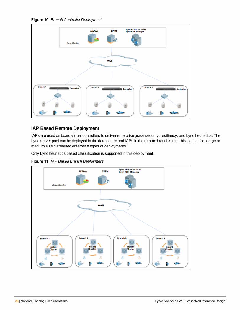
Figure 10 Branch Controller Deployment
IAP Based Remote DeploymentIAPs are used on board virtual controllers to deliver enterprise grade security, resiliency, and Lync heuristics. TheLync server pool can be deployed in the data center and IAPs in the remote branch sites, this is ideal for a large ormedium size distributed enterprise types of deployments.
Only Lync heuristics based classification is supported in this deployment.
Figure 11 IAP Based Branch Deployment
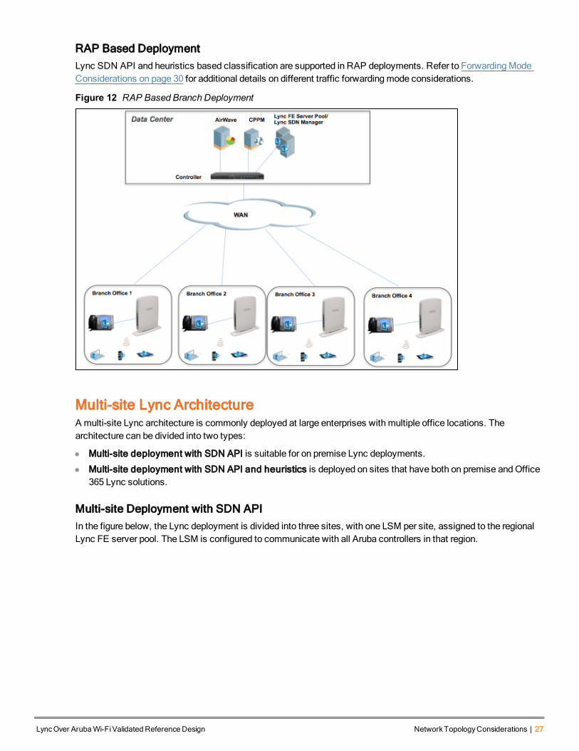
RAP Based DeploymentLync SDN API and heuristics based classification are supported in RAP deployments. Refer to ForwardingModeConsiderations on page 30 for additional details on different traffic forwardingmode considerations.
Figure 12 RAP Based Branch Deployment
Multi-site Lync ArchitectureA multi-site Lync architecture is commonly deployed at large enterprises with multiple office locations. Thearchitecture can be divided into two types:
l Multi-site deployment with SDN API is suitable for on premise Lync deployments.
l Multi-site deployment with SDN API and heuristics is deployed on sites that have both on premise andOffice365 Lync solutions.
Multi-site Deployment with SDN APIIn the figure below, the Lync deployment is divided into three sites, with one LSM per site, assigned to the regionalLync FE server pool. The LSM is configured to communicate with all Aruba controllers in that region.
LyncOver ArubaWi-FiValidated Reference Design NetworkTopologyConsiderations | 27

28 | NetworkTopologyConsiderations LyncOver ArubaWi-FiValidated Reference Design
Figure 13 Multi-site Lync Architecture with SDN API
The following guidelines should be applied tomulti-site architectures with SDN API:
l One Lync FE server pool per region, for example, North America or Europe.
l One LSM per region.
l LSM configured to communicate with all Aruba controllers in that region.
l All Lync clients in a region are served by the front end servers in that region.
l Lync calls across multiple regions aremanaged by the local front end server in that region.
Check with your local VAR or Aruba Lync expert on the number of Aruba controllers and Lync clients that can bemanaged by the LSM and FE server pool.
Multi-site Deployment with SDN API and HeuristicsThe figure below describes a Lync topology with both on premise Lync servers andOffice 365 Lync online. Office365 is only supported with heuristics based classification. Starting with ArubaOS 6.4, controllers can simultaneouslyenable both heuristics and SDN API based classification.
Figure 14 Multi site Lync Architecture with On-Premise andOffice 365
Guest and BYOD Access TopologyIn this topology network security is context-based, in this model there is no L1/L2 separation, one common networkis shared between all users/devices/applications, and security is achieved through contextually enforced profiles(roles) assigned to users and devices.
The following guidelines should be applied to Bring Your OwnDevice (BYOD) networks:
1. Configure the user roles and network access rules for employee, guest, and BYOD profiles.
2. Apply Lync ACL to a specific user role such as Guest, or employees for whom Lync traffic needs to be classifiedand prioritized. Without a Lync ACL, the Lync traffic will be treated as best effort and not prioritized, and the userexperience will suffer.
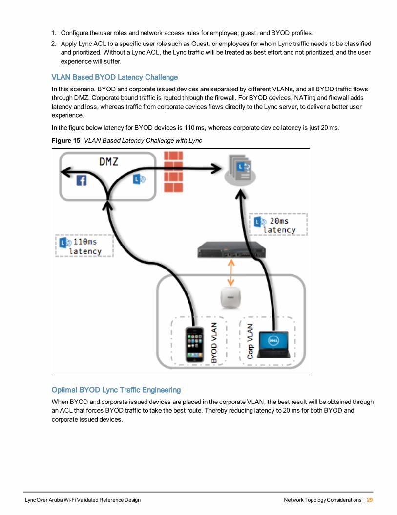
VLAN Based BYOD Latency Challenge
In this scenario, BYOD and corporate issued devices are separated by different VLANs, and all BYOD traffic flowsthrough DMZ. Corporate bound traffic is routed through the firewall. For BYOD devices, NATing and firewall addslatency and loss, whereas traffic from corporate devices flows directly to the Lync server, to deliver a better userexperience.
In the figure below latency for BYOD devices is 110ms, whereas corporate device latency is just 20ms.
Figure 15 VLAN Based Latency Challenge with Lync
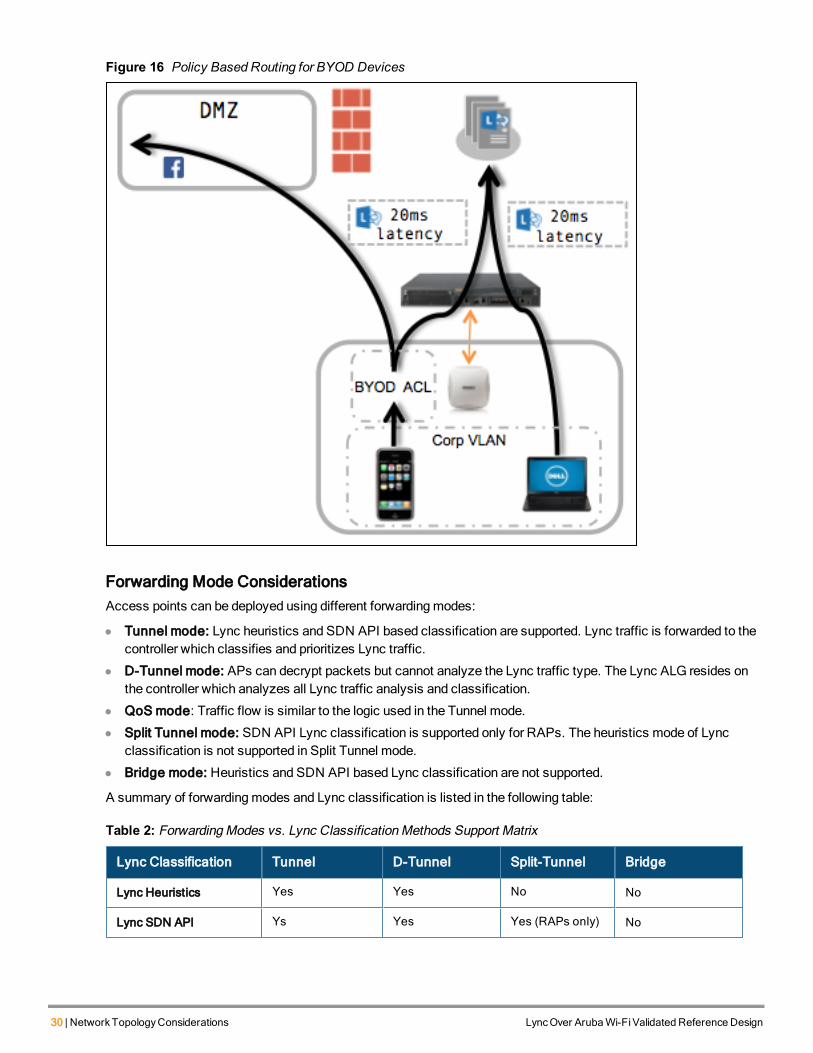
Optimal BYOD Lync Traffic Engineering
When BYOD and corporate issued devices are placed in the corporate VLAN, the best result will be obtained throughan ACL that forces BYOD traffic to take the best route. Thereby reducing latency to 20ms for both BYOD andcorporate issued devices.
LyncOver ArubaWi-FiValidated Reference Design NetworkTopologyConsiderations | 29
30 | NetworkTopologyConsiderations LyncOver ArubaWi-FiValidated Reference Design
Figure 16 Policy Based Routing for BYOD Devices
Forwarding Mode ConsiderationsAccess points can be deployed using different forwardingmodes:
l Tunnel mode: Lync heuristics and SDN API based classification are supported. Lync traffic is forwarded to thecontroller which classifies and prioritizes Lync traffic.
l D-Tunnel mode: APs can decrypt packets but cannot analyze the Lync traffic type. The Lync ALG resides onthe controller which analyzes all Lync traffic analysis and classification.
l QoS mode: Traffic flow is similar to the logic used in the Tunnel mode.
l Split Tunnel mode: SDN API Lync classification is supported only for RAPs. The heuristics mode of Lyncclassification is not supported in Split Tunnel mode.
l Bridge mode: Heuristics and SDN API based Lync classification are not supported.
A summary of forwardingmodes and Lync classification is listed in the following table:
Lync Classification Tunnel D-Tunnel Split-Tunnel Bridge
Lync Heuristics Yes Yes No No
Lync SDN API Ys Yes Yes (RAPs only) No
Table 2: ForwardingModes vs. Lync ClassificationMethods Support Matrix

LyncOver ArubaWi-FiValidated Reference Design QoS | 31
Chapter 9QoS
Aruba’s Policy Enforcement Firewall (PEF) is a stateful firewall that applies policies to user roles and trafficsessions. Among other functions, the PEF can dynamically reclassify traffic, using firewall policies, and applicationlayer gateways to prevent abuse and prioritize traffic whose tags are otherwisemismarked. Aruba controller trafficclassification use cases are described below.
Classifying Unmarked TrafficWhen traffic with no DSCP or 802.1pmarkings reaches a controller, it is compared with the policy assigned to theuser role. Based on the class that the traffic is classified, the controller marks the traffic and forwards it. Forexample, traffic classified at the voice session level. If the traffic is unmarked and the controller determines that itshould not bemarked, it is forwarded without any modifications. The figure below illustrates traffic marking.
Figure 17 Classifying Unmarked Traffic
Incoming Traffic is MarkedMarked traffic is compared to the system policy. If themarks are correct for the policy and traffic type, the traffic isforwarded without any modifications.
32 | QoS LyncOver ArubaWi-FiValidated Reference Design
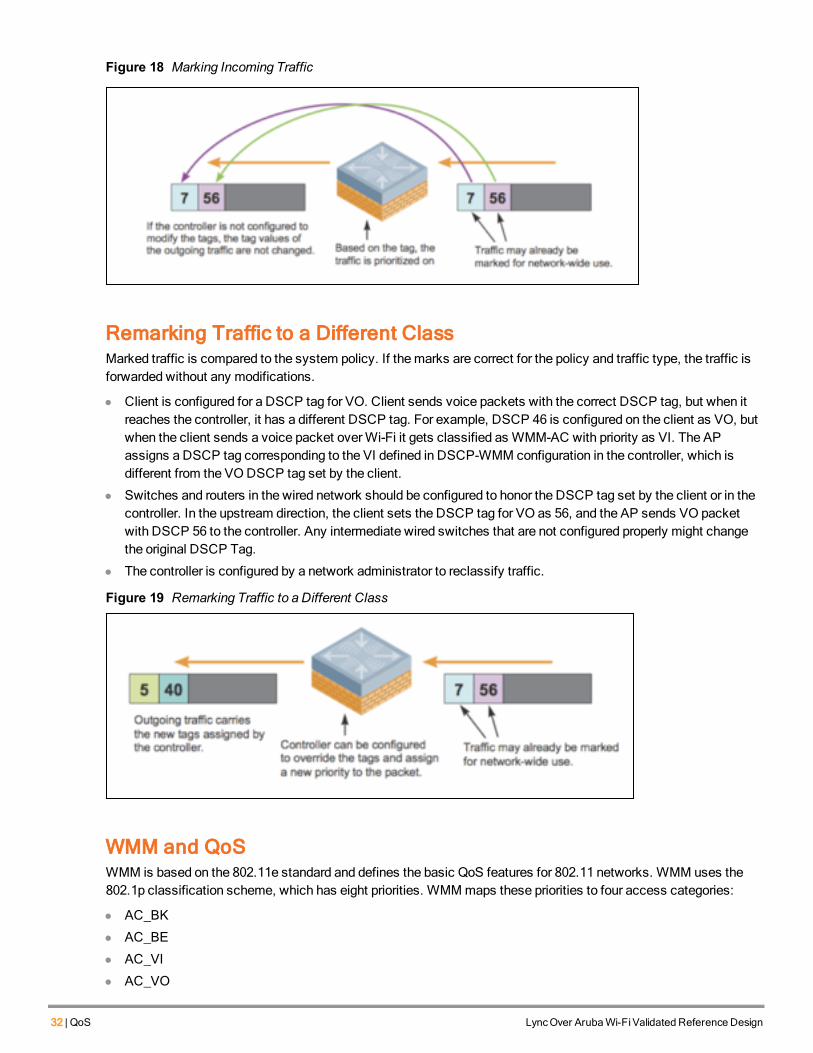
Figure 18 Marking Incoming Traffic
Remarking Traffic to a Different ClassMarked traffic is compared to the system policy. If themarks are correct for the policy and traffic type, the traffic isforwarded without any modifications.
l Client is configured for a DSCP tag for VO. Client sends voice packets with the correct DSCP tag, but when itreaches the controller, it has a different DSCP tag. For example, DSCP 46 is configured on the client as VO, butwhen the client sends a voice packet overWi-Fi it gets classified as WMM-AC with priority as VI. The APassigns a DSCP tag corresponding to the VI defined in DSCP-WMM configuration in the controller, which isdifferent from the VODSCP tag set by the client.
l Switches and routers in the wired network should be configured to honor the DSCP tag set by the client or in thecontroller. In the upstream direction, the client sets the DSCP tag for VO as 56, and the AP sends VO packetwith DSCP 56 to the controller. Any intermediate wired switches that are not configured properly might changethe original DSCP Tag.
l The controller is configured by a network administrator to reclassify traffic.
Figure 19 Remarking Traffic to a Different Class
WMM and QoSWMM is based on the 802.11e standard and defines the basic QoS features for 802.11 networks. WMM uses the802.1p classification scheme, which has eight priorities. WMMmaps these priorities to four access categories:
l AC_BK
l AC_BE
l AC_VI
l AC_VO
These access categories map to four queues required by WMM devices as shown in the following table.
Priority 802.1P Priority 802.1P Designation Access Category WMMDesignation
Lowest 1 BK AC_BK Background
2 BK
0 BE AC_BE Best Effort
3 EE
4 CL AC_VI Video
5 VI
6 VO AC_VO Voice
Highest 7 NC
Table 3: 802.11p andWMM-AC Classification
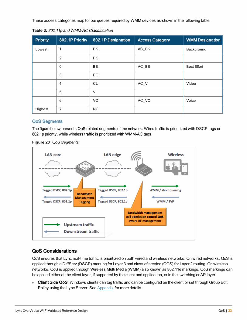
QoS Segments
The figure below presents QoS related segments of the network. Wired traffic is prioritized with DSCP tags or802.1p priority, while wireless traffic is prioritized withWMM-AC tags.
Figure 20 QoS Segments
QoS ConsiderationsQoS ensures that Lync real-time traffic is prioritized on both wired and wireless networks. On wired networks, QoS isapplied through a DiffServ (DSCP)marking for Layer 3 and class of service (COS) for Layer 2 routing. On wirelessnetworks, QoS is applied throughWireless Multi Media (WMM) also known as 802.11emarkings. QoS markings canbe applied either at the client layer, if supported by the client and application, or in the switching or AP layer.
l Client Side QoS: Windows clients can tag traffic and can be configured on the client or set throughGroup EditPolicy using the Lync Server. See Appendix for more details.
LyncOver ArubaWi-FiValidated Reference Design QoS | 33

34 | QoS LyncOver ArubaWi-FiValidated Reference Design
l Controller QoS Configuration: DSCP-WMMmapping can be done on the controller where DSCP values canbe set for different application categories such as VO/VI/BE/BK.
Figure 21 DSCP-WMM Mapping Configuration
Lync SDN API tags Lync Desktop-Sharing with the Video DSCP tag and the Lync File Transfer traffic is marked with abest effort DSCP tag.
l AP QoS Considerations: In a controller environment, DSCP-WMM configuration is forwarded to the APs. TheAPs translateWMM <> DSCP values according to this mapping while sending traffic both upstream (wirelessclient to controller) and downstream (controller to wireless client).
n The DSCP tag is placed outside the GRE header when the AP sends the packet to the controller.
l IAP QoS Configuration: IAP version 6.4.0.2-4.1 and higher enables the IAP to customizeWi-Fi multimedia toDSCP mapping configuration for upstream (client to IAP) and downstream (IAP to client) traffic. The followingtable presents DSCP toWMMmappings for different traffic types. For example, if incoming traffic type is markedwith DSCP 48 or 56 then it is linked to theWMM voice queue.
DSCP Decimal Value Description
8 Background
16
0 Best Effort
24
32 Video
40
48 Voice
56
Table 4: DSCP-WMMConfiguration IAP

Customizedmappings can be created betweenWMMAC and the DSCP tag to prioritize traffic types and applythese changes to aWMM-enabled SSID profile. WhenWMMAC mapping values are configured, all packetsreceived arematched against the entries in themapping table and prioritized accordingly.
Refer to the IAP 6.4.0.2-4.1 CLI ReferenceGuide for the DSCP-WMM configuration. Customized DSCP-WMMconfiguration was not supported prior to IAP 6.4.0.2-4.1 and earlier IAP versions mapped DSCP 48 to voice trafficand DSCP 40 to video traffic.
QoS Flow
The use cases below demonstrate how QoS is translated for different call scenarios such as wireless-to-wirelessand wireless-to wired calls. The use cases apply toWMM-only mode (no Lync voice classification or prioritization),Lync heuristics, and SDN API modes. These use cases are described under the tunnel forwardingmode ofoperation.
WMMOnly Mode
Client A initiates a Lync voice call to client B and client-A is not tagging Lync voice traffic.
Figure 22 QoS Flow inWMMOnly Mode
a. In upstream direction (Client to Controller), AP looks at L2 Priority (WMM-AC as BE) and sets DSCP 24 asper DSCP-WMMmapping in the controller.
b. The controller decrypts the packet and uses L2 priority to assign DSCP 24 in the downstream direction(controller to client).
c. The AP assigns WMM-AC as BE corresponding to the DSCP-WMMmapping on the controller.
Lync Best effort traffic is sent with Best Effort Priority in entire network.
Heuristics Mode
Client A initiates a Lync voice call to client B but client A does not tag Lync voice traffic. The controller is configuredto detect Lync VO traffic through heuristics.
LyncOver ArubaWi-FiValidated Reference Design QoS | 35

36 | QoS LyncOver ArubaWi-FiValidated Reference Design
Figure 23 QoS Flow in Heuristics Mode
a. In upstream direction (client to controller) the AP looks at L2 Priority (WMM-AC as BE) and allocates theDSCP 24 according to the DSCM-WMMmapping in the controller.
b. The controller identifies the Lync VO traffic type using heuristics and corrects the DSCP tag to 46 in thedownstream direction (controller to client).
c. AP assigns WMM-AC as VO as per DSCP-WMMmapping in the controller.
Lync voice traffic gets best effort priority in upstream direction, but gets corrected to VO priority in downstream direction.
SDN API Mode
QoS flows in the Lync SDN API are identical to QoS flows in the heuristics mode. The Lync SDN API module on theLync server sends Lync VO traffic type information to the controller when client A initiates a voice call to client B.
Wired to Wireless
This use case applies to Lync VO calls between a wired client and a wireless client, either with Lync heuristics orLync SDN API based classification.
Figure 24 QoS Flow Wired toWireless
a. In upstream direction (wired client to wireless client) the controller locates Lync VO traffic in data path andassigns DSCP 46 per DSCP-WMMmapping. The AP assigns WMMVO per the DSCP-WMMmapping.
b. In downstream direction (wireless client to wired client), the AP looks at L2 Priority (WMM-AC as BE) andsets DSCP 24 per DSCM-WMMmapping in the controller.
c. The controller locates a Lync VO packet and sets DSCP tag to 46 for VOwhen sending the packet to thewired Lync client.
Wireless to Wired
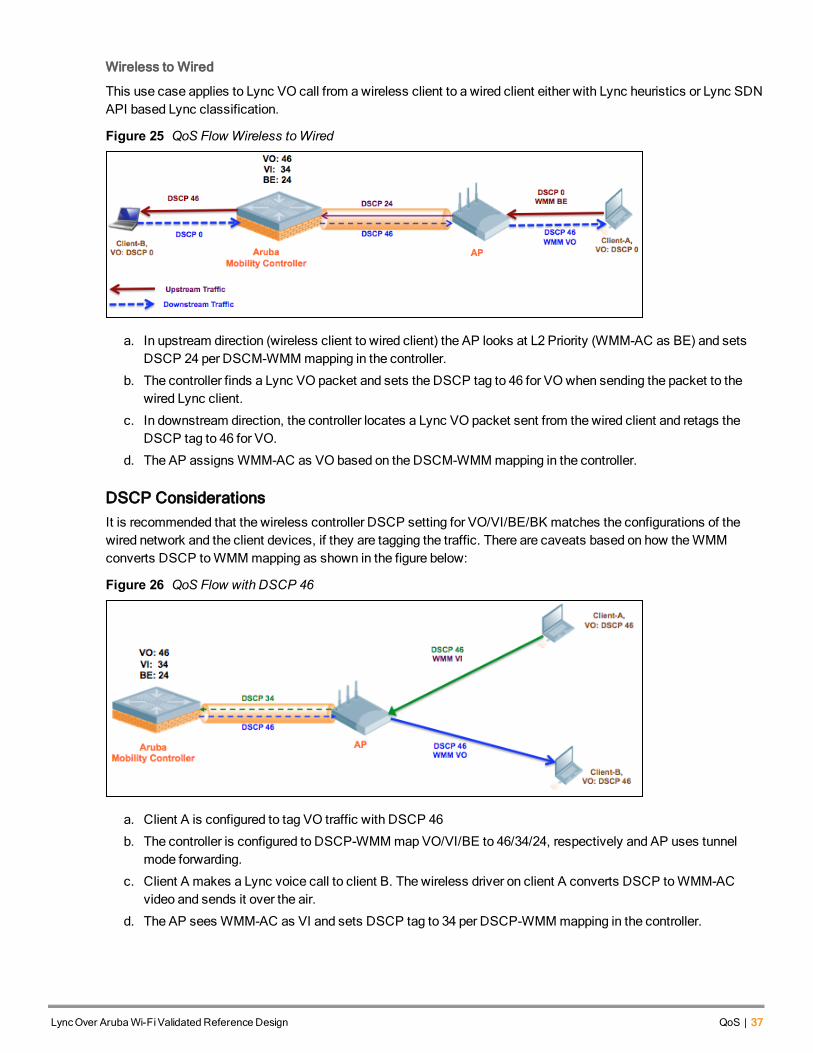
This use case applies to Lync VO call from awireless client to a wired client either with Lync heuristics or Lync SDNAPI based Lync classification.
Figure 25 QoS Flow Wireless toWired
a. In upstream direction (wireless client to wired client) the AP looks at L2 Priority (WMM-AC as BE) and setsDSCP 24 per DSCM-WMMmapping in the controller.
b. The controller finds a Lync VO packet and sets the DSCP tag to 46 for VOwhen sending the packet to thewired Lync client.
c. In downstream direction, the controller locates a Lync VO packet sent from the wired client and retags theDSCP tag to 46 for VO.
d. The AP assigns WMM-AC as VO based on the DSCM-WMMmapping in the controller.
DSCP ConsiderationsIt is recommended that the wireless controller DSCP setting for VO/VI/BE/BK matches the configurations of thewired network and the client devices, if they are tagging the traffic. There are caveats based on how theWMMconverts DSCP toWMMmapping as shown in the figure below:
Figure 26 QoS Flow with DSCP 46
a. Client A is configured to tag VO traffic with DSCP 46
b. The controller is configured to DSCP-WMMmap VO/VI/BE to 46/34/24, respectively and AP uses tunnelmode forwarding.
c. Client A makes a Lync voice call to client B. The wireless driver on client A converts DSCP toWMM-ACvideo and sends it over the air.
d. The AP sees WMM-AC as VI and sets DSCP tag to 34 per DSCP-WMMmapping in the controller.
LyncOver ArubaWi-FiValidated Reference Design QoS | 37
38 | QoS LyncOver ArubaWi-FiValidated Reference Design
VO traffic is sent with VI priority in the upstream direction. However, there is an issue with the way in which thewireless driver interprets DSCP and converts it toWMM-AC. The following table outlines how the DSCP values areinterpreted by WMM.
DSCP Decimal Value Description
48-63 VO
32-47 VI
22-31 BE
0-21 BK
Table 5: DSCP toWMM-AC Mapping
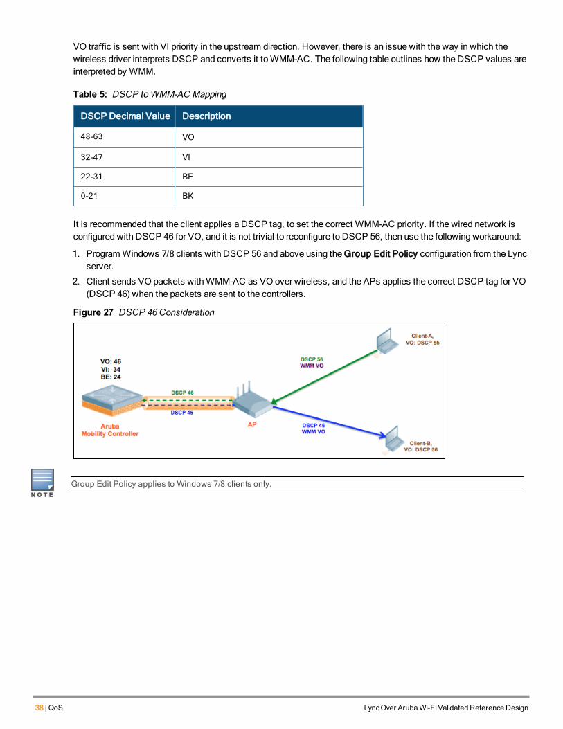
It is recommended that the client applies a DSCP tag, to set the correct WMM-AC priority. If the wired network isconfigured with DSCP 46 for VO, and it is not trivial to reconfigure to DSCP 56, then use the following workaround:
1. ProgramWindows 7/8 clients with DSCP 56 and above using the Group Edit Policy configuration from the Lyncserver.
2. Client sends VO packets withWMM-AC as VO over wireless, and the APs applies the correct DSCP tag for VO(DSCP 46) when the packets are sent to the controllers.
Figure 27 DSCP 46 Consideration
Group Edit Policy applies to Windows 7/8 clients only.
LyncOver ArubaWi-FiValidated Reference Design DSCP-EF 46 andWMM | 39
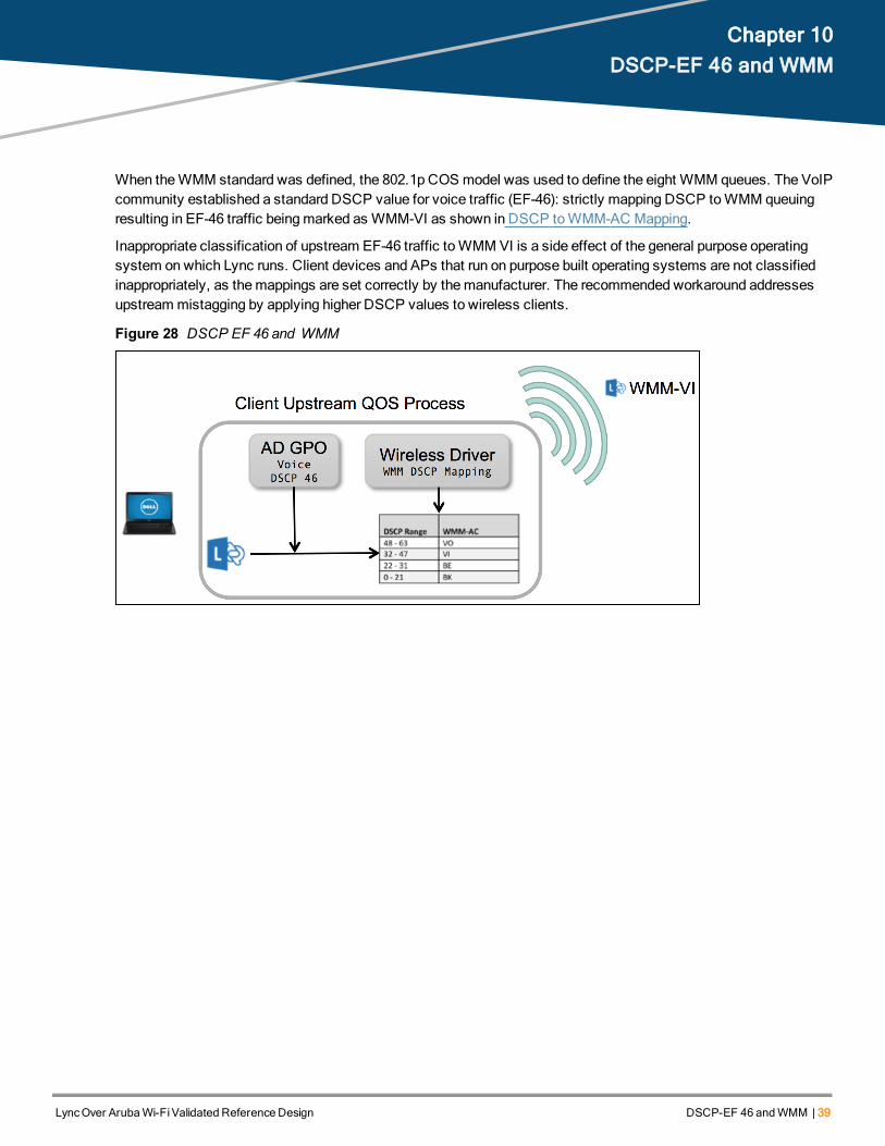
Chapter 10DSCP-EF 46 and WMM
When theWMM standard was defined, the 802.1p COS model was used to define the eight WMM queues. The VoIPcommunity established a standard DSCP value for voice traffic (EF-46): strictly mapping DSCP toWMM queuingresulting in EF-46 traffic beingmarked as WMM-VI as shown in DSCP toWMM-AC Mapping.
Inappropriate classification of upstream EF-46 traffic toWMMVI is a side effect of the general purpose operatingsystem onwhich Lync runs. Client devices and APs that run on purpose built operating systems are not classifiedinappropriately, as themappings are set correctly by themanufacturer. The recommended workaround addressesupstreammistagging by applying higher DSCP values to wireless clients.
Figure 28 DSCP EF 46 and WMM
LyncOver ArubaWi-FiValidated Reference Design Lyncon VDI | 40
Chapter 11Lync on VDI
Virtual Desktop Infrastructure (VDI) is a centralized desktop delivery solution that stores and runs desktopworkloads, enabling users to interact with the desktop through a remote connection. VDI includes a client operatingsystem, applications, and data stored in a server based virtual machine (VM) in data centers.
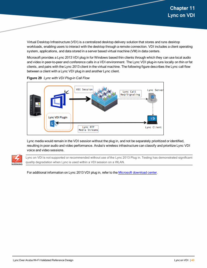
Microsoft provides a Lync 2013 VDI plug in forWindows based thin clients through which they can use local audioand video in peer-to-peer and conference calls in a VDI environment. The Lync VDI plug-in runs locally on thin or fatclients, and pairs with the Lync 2013 client in the virtual machine. The following figure describes the Lync call flowbetween a client with a Lync VDI plug in and another Lync client.
Figure 29 Lync with VDI Plug-in Call Flow
Lync media would remain in the VDI session without the plug in, and not be separately prioritized or identified,resulting in poor audio and video performance. Aruba’s wireless infrastructure can classify and prioritize Lync VDIvoice and video sessions.
Lync on VDI is not supported or recommended without use of the Lync 2013 Plug in. Testing has demonstrated significantquality degradation when Lync is used within a VDI session on a WLAN.
For additional information on Lync 2013 VDI plug in, refer to theMicrosoft download center.
LyncOver ArubaWi-FiValidated Reference Design ScalabilityConsiderations | 41
Chapter 12Scalability Considerations
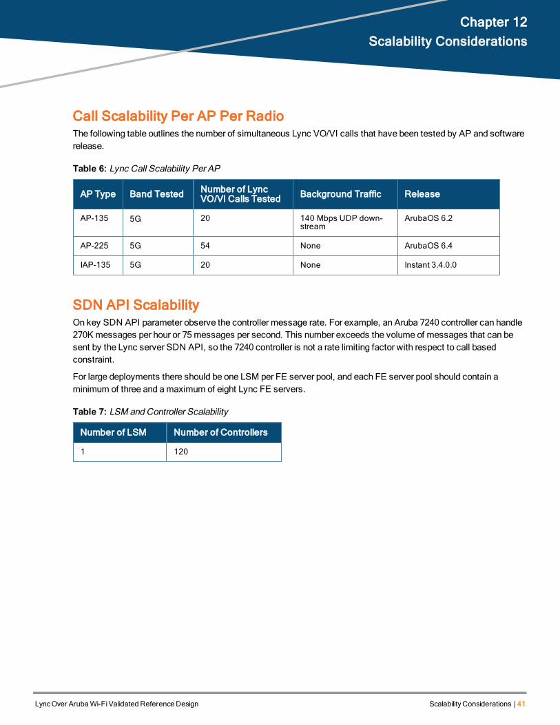
Call Scalability Per AP Per RadioThe following table outlines the number of simultaneous Lync VO/VI calls that have been tested by AP and softwarerelease.
AP Type Band Tested Number of LyncVO/VI Calls Tested Background Traffic Release
AP-135 5G 20 140 Mbps UDP down-stream
ArubaOS 6.2
AP-225 5G 54 None ArubaOS 6.4
IAP-135 5G 20 None Instant 3.4.0.0
Table 6: Lync Call Scalability Per AP
SDN API ScalabilityOn key SDN API parameter observe the controller message rate. For example, an Aruba 7240 controller can handle270K messages per hour or 75messages per second. This number exceeds the volume of messages that can besent by the Lync server SDN API, so the 7240 controller is not a rate limiting factor with respect to call basedconstraint.
For large deployments there should be one LSM per FE server pool, and each FE server pool should contain aminimum of three and amaximum of eight Lync FE servers.
Number of LSM Number of Controllers
1 120
Table 7: LSM andController Scalability
LyncOver ArubaWi-FiValidated Reference Design Aruba Solution for LyncE911 | 42
Chapter 13Aruba Solution for Lync E911
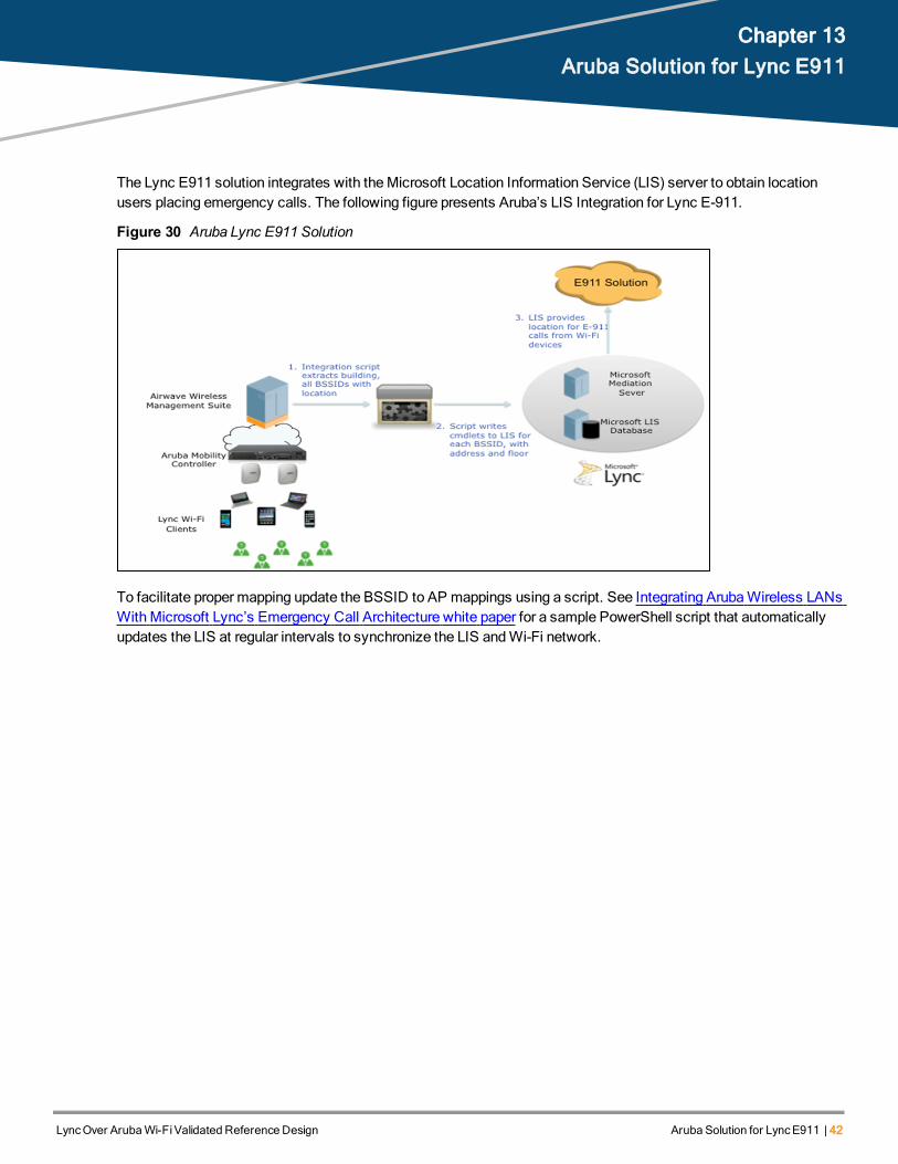
The Lync E911 solution integrates with theMicrosoft Location Information Service (LIS) server to obtain locationusers placing emergency calls. The following figure presents Aruba’s LIS Integration for Lync E-911.
Figure 30 Aruba Lync E911 Solution
To facilitate proper mapping update the BSSID to AP mappings using a script. See Integrating ArubaWireless LANsWithMicrosoft Lync’s Emergency Call Architecture white paper for a sample PowerShell script that automaticallyupdates the LIS at regular intervals to synchronize the LIS andWi-Fi network.
LyncOver ArubaWi-FiValidated Reference Design Troubleshooting | 43
Chapter 14Troubleshooting
SDN Integration TroubleshootingThe following section lists troubleshooting steps for Lync SDN API issues.
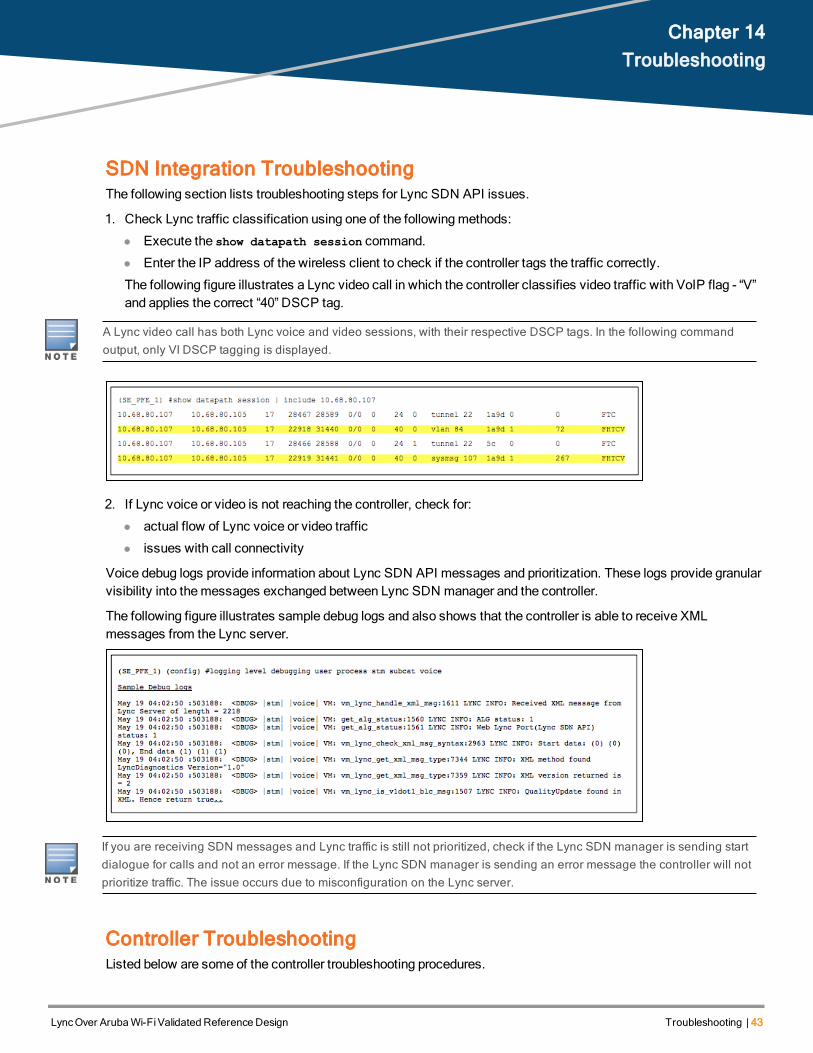
1. Check Lync traffic classification using one of the followingmethods:
l Execute the show datapath session command.
l Enter the IP address of the wireless client to check if the controller tags the traffic correctly.
The following figure illustrates a Lync video call in which the controller classifies video traffic with VoIP flag - “V”and applies the correct “40” DSCP tag.
A Lync video call has both Lync voice and video sessions, with their respective DSCP tags. In the following commandoutput, only VI DSCP tagging is displayed.
2. If Lync voice or video is not reaching the controller, check for:
l actual flow of Lync voice or video traffic
l issues with call connectivity
Voice debug logs provide information about Lync SDN API messages and prioritization. These logs provide granularvisibility into themessages exchanged between Lync SDN manager and the controller.
The following figure illustrates sample debug logs and also shows that the controller is able to receive XMLmessages from the Lync server.
If you are receiving SDN messages and Lync traffic is still not prioritized, check if the Lync SDN manager is sending startdialogue for calls and not an error message. If the Lync SDN manager is sending an error message the controller will notprioritize traffic. The issue occurs due to misconfiguration on the Lync server.
Controller TroubleshootingListed below are some of the controller troubleshooting procedures.

44 | Troubleshooting LyncOver ArubaWi-FiValidated Reference Design
l If the UCC dashboard is not displayed after the SDN API is installed and configured, ensure that voice real-time-config is enabled as shown in the following example.#configure terminal
(config) #voice real-time-config
(Configure Real-Time Analysis) #config-enable
l DSCP toWMMmapping for VO/VI/BE/BK traffic types are defined in SSID profile in the controller as shown inthe following example.
The controller prioritizes different Lync traffic types as per the above configuration. To verify if the controller is able toprioritize Lync traffic and is applying the correct QoS, see the show datapath session output in the SDNIntegration Troubleshooting section.
l The performance dashboard provides real-time visibility into various performancemetrics on the system. Thisfeature provides a quick health overview of the clients and APs and also drills down to an individual client or AP ifany RF related issue needs troubleshooting. The feature provides further insight into throughput metrics of thesystem andWi-Fi quality.
The following figure provides detailed information of an AP, client, and application usage. You can further drill downtomonitor client throughput, usage by WLAN, usage by applications, and related information.

AP TroubleshootingIf the QoS is appropriately applied by the controller and users are still experiencing Lync issues use the followingtroubleshooting steps:
l RF packet captures provides 802.11 header related information and also helps in determining whether Lync trafficis sent from the AP to the client with the appropriateWMM-AC priority.
l The controller allows you tomonitor radio statistics and provides details on the number of transmitted/droppedpackets inWMMVO/VI queues. The number of packets dropped for Lync voice/video traffic should be low sincethis traffic gets prioritized over BE/BK traffic. If the count of the voice/video packet dropped is high, QoS does notapply to the AP.
The following figure illustrates an AP debug screen. Reset the AP debug counter and initiate new Lyncvoice/video calls on that AP to verify voice/video Tx WMM packet drop counters.
Execute the following command for statistics on individual clients - show ap debug client-stats <client-MAC>.
LyncOver ArubaWi-FiValidated Reference Design Troubleshooting | 45

46 | Troubleshooting LyncOver ArubaWi-FiValidated Reference Design
RF Troubleshootingl RF packet captures provide visibility to 802.11 headers to determine if Lync traffic is sent with the correct WMM-
AC priority. If the wireless client is tagging the traffic, ensure that theWMM-AC upstream traffic priority from theclient matches the DSCP tag configured on the client.
Also ensure that the Lync traffic type is marked with the correct WMM- AC priority in the downstream directionfrom the AP to the client.
l RF packet captures provide useful information such as packet retries/failures, data rates, beacon rates, and soon. These RF environment attributes can be helpful to troubleshoot Lync related issues.
Wired Network Troubleshootingl End-to-endQoS helps achieve optimum Lync performance. Ensure that the switches/routers in the wired network
honor the QoS settings. There is a known issue with some of the wired switches such as Cisco 3750 that canreset the DSCP tag to 0 for all egress traffic if QoS is not enabled on that switch. Packet capture on the wirednetwork will show DSCP tagging details.
l Ensure that the wired network has adequate bandwidth to handle the volume of Lync traffic. Lync bandwidthusage varies, but is predictable. For network bandwidth requirements of Lync codecs see Network bandwidthrequirements for media traffic in Lync Server 2013.
Lync Troubleshooting Using UCC Dashboard and CLI commandsArubaOS 6.4 provides a dashboard tab that displays system and client visibility into Lync calls. To access the newdashboard tab navigate to Dashboard->UCC.
From themain UCC dashboard you can view system-wide UCC counters and statistics for call volume, call quality,call/client health correlation, per device call counters, call roaming statistics, andQoS correction statistics. From thecall volume section you can view:
l Call distribution by an AP
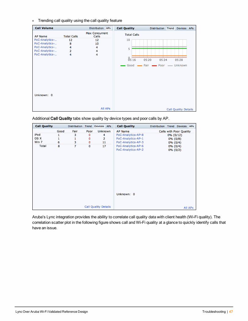
l Trending call quality using the call quality feature
Additional Call Quality tabs show quality by device types and poor calls by AP.
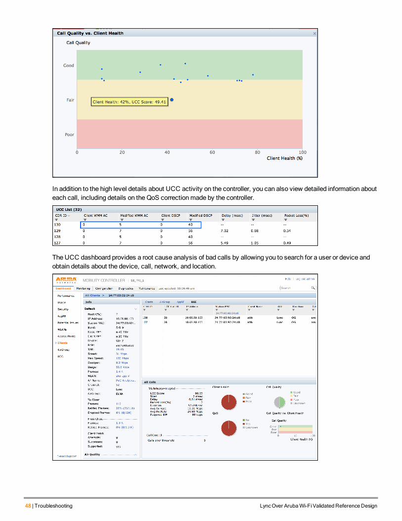
Aruba's Lync integration provides the ability to correlate call quality data with client health (Wi-Fi quality). Thecorrelation scatter plot in the following figure shows call andWi-Fi quality at a glance to quickly identify calls thathave an issue.
LyncOver ArubaWi-FiValidated Reference Design Troubleshooting | 47
48 | Troubleshooting LyncOver ArubaWi-FiValidated Reference Design
In addition to the high level details about UCC activity on the controller, you can also view detailed information abouteach call, including details on the QoS correctionmade by the controller.
The UCC dashboard provides a root cause analysis of bad calls by allowing you to search for a user or device andobtain details about the device, call, network, and location.
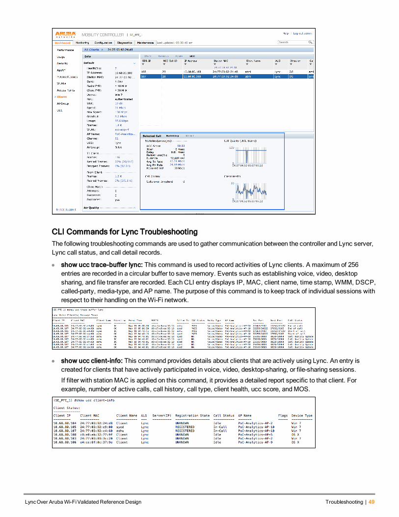
CLI Commands for Lync TroubleshootingThe following troubleshooting commands are used to gather communication between the controller and Lync server,Lync call status, and call detail records.
l show ucc trace-buffer lync: This command is used to record activities of Lync clients. A maximum of 256entries are recorded in a circular buffer to savememory. Events such as establishing voice, video, desktopsharing, and file transfer are recorded. Each CLI entry displays IP, MAC, client name, time stamp, WMM, DSCP,called-party, media-type, and AP name. The purpose of this command is to keep track of individual sessions withrespect to their handling on theWi-Fi network.
l show ucc client-info: This command provides details about clients that are actively using Lync. An entry iscreated for clients that have actively participated in voice, video, desktop-sharing, or file-sharing sessions.
If filter with stationMAC is applied on this command, it provides a detailed report specific to that client. Forexample, number of active calls, call history, call type, client health, ucc score, andMOS.
LyncOver ArubaWi-FiValidated Reference Design Troubleshooting | 49
50 | Troubleshooting LyncOver ArubaWi-FiValidated Reference Design
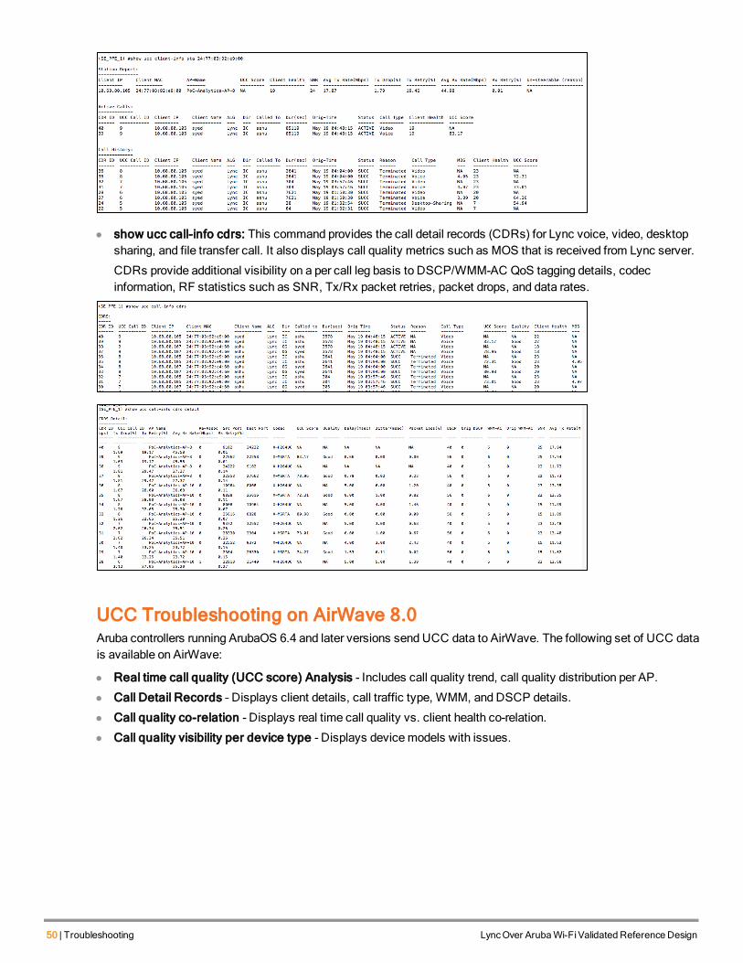
l show ucc call-info cdrs: This command provides the call detail records (CDRs) for Lync voice, video, desktopsharing, and file transfer call. It also displays call quality metrics such as MOS that is received from Lync server.
CDRs provide additional visibility on a per call leg basis to DSCP/WMM-AC QoS tagging details, codecinformation, RF statistics such as SNR, Tx/Rx packet retries, packet drops, and data rates.
UCC Troubleshooting on AirWave 8.0Aruba controllers running ArubaOS 6.4 and later versions send UCC data to AirWave. The following set of UCC datais available on AirWave:
l Real time call quality (UCC score) Analysis - Includes call quality trend, call quality distribution per AP.
l Call Detail Records – Displays client details, call traffic type, WMM, and DSCP details.
l Call quality co-relation - Displays real time call quality vs. client health co-relation.
l Call quality visibility per device type - Displays devicemodels with issues.
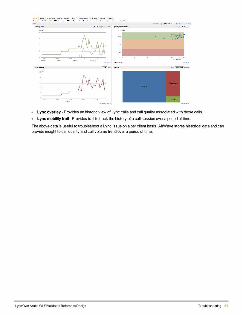
l Lync overlay - Provides an historic view of Lync calls and call quality associated with those calls.
l Lync mobility trail - Provides trail to track the history of a call session over a period of time.
The above data is useful to troubleshoot a Lync issue on a per client basis. AirWave stores historical data and canprovide insight to call quality and call volume trend over a period of time.
LyncOver ArubaWi-FiValidated Reference Design Troubleshooting | 51
LyncOver ArubaWi-FiValidated Reference Design Appendix | 52
Chapter 15Appendix
This chapter provides information on installing and configuring Lync over the Aruba network.
Lync SDN API Installation and Configuration Guidelines
Lync Server Side ConfigurationLync Dialog Listener (LDL)must be installed and configured on the Lync front end server. Lync SDN Manager (LSM)must be installed on a separateWindows 2008/2012 server and not on the Lync front end server. If there aremultiplefront end servers, LDLmust be installed on each front end server and configured to point to the LSM. Aruba controllerinformation should be configured on the LSM. Download the Lync SDN API 2.0 from theMicrosoft support site.
For more information on installation instructions, see the installation instruction SDN API 2.0 PDF to install LDL and LSM.
Lync Dialog Listener Configuration
Follow the steps below to configure LDL:
1. Enter Primary/Secondary SDN Manager URI.
2. Enter the path to place log files.
3. Replace sdnmanager with SDN Manager IP address in Primary/Secondary SDN Manager URI field.
The SDN Manager IP addresses from SDN Manager URI fields are automatically populated in theLyncDialogListener.exe.config file.
53 | Appendix LyncOver ArubaWi-FiValidated Reference Design
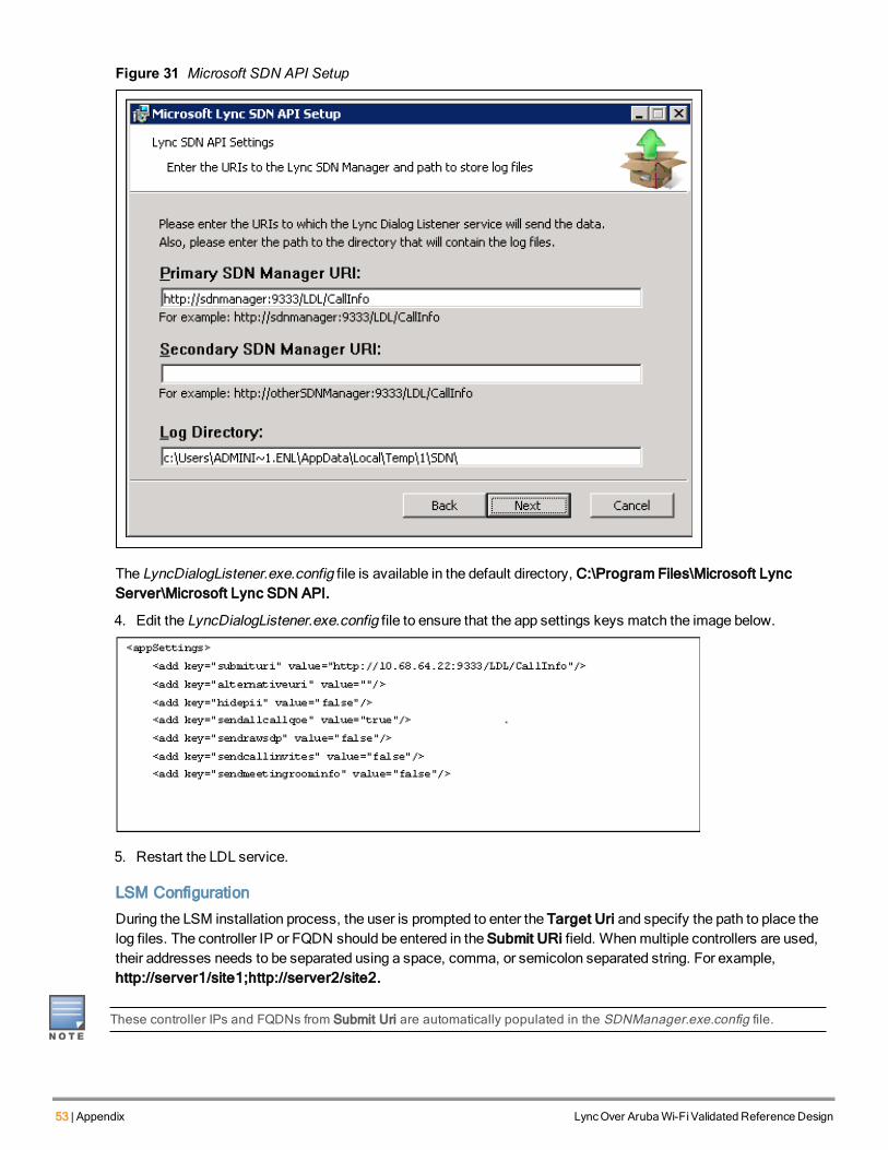
Figure 31 Microsoft SDN API Setup
The LyncDialogListener.exe.config file is available in the default directory, C:\Program Files\Microsoft LyncServer\Microsoft Lync SDN API.
4. Edit the LyncDialogListener.exe.config file to ensure that the app settings keys match the image below.
5. Restart the LDL service.
LSM Configuration
During the LSM installation process, the user is prompted to enter the Target Uri and specify the path to place thelog files. The controller IP or FQDN should be entered in the Submit URi field. Whenmultiple controllers are used,their addresses needs to be separated using a space, comma, or semicolon separated string. For example,http://server1/site1;http://server2/site2.
These controller IPs and FQDNs from Submit Uri are automatically populated in the SDNManager.exe.config file.

Figure 32 Microsoft Lync SDN Manager Setup
After installing the API you can edit the SDNManager.exe.config configuration file to add new additional controller IPaddresses. The SDNManager.exe.config file is located in the Lync SDN API’s installation directory. The wirelesscontroller IP address/host name and transport mode (http/https) are configured in this file. By default, the path to thisdirectory is C:\Program Files\Microsoft Lync Server\Microsoft Lync SDN API.
Figure 33 Lync SDN API’s Installation Directory
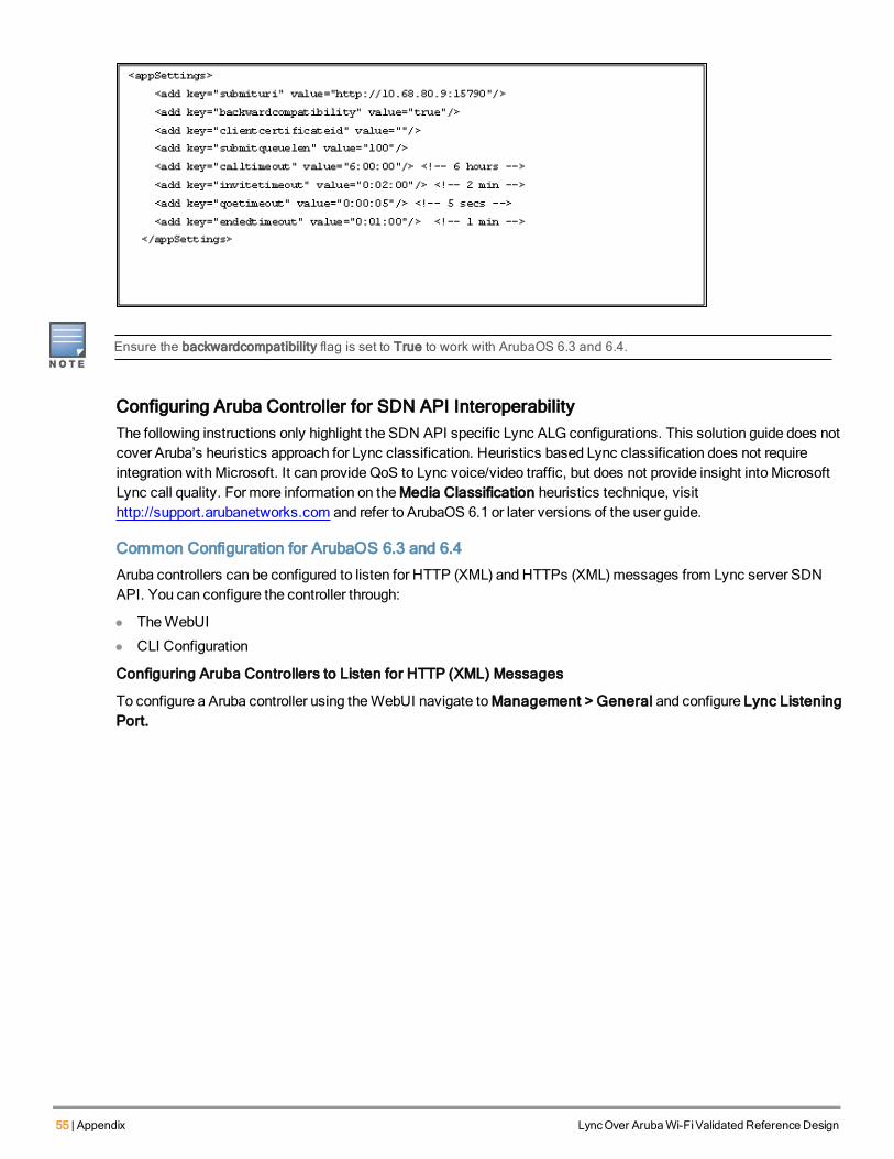
Edit the SDNManager.exe.config file to add/edit controller IP addresses or URLs as defined below and ensure theapp settings keys match the image below. Restart the LSM service if any changes aremade to the configuration file.
LyncOver ArubaWi-FiValidated Reference Design Appendix | 54
55 | Appendix LyncOver ArubaWi-FiValidated Reference Design
Ensure the backwardcompatibility flag is set to True to work with ArubaOS 6.3 and 6.4.
Configuring Aruba Controller for SDN API InteroperabilityThe following instructions only highlight the SDN API specific Lync ALG configurations. This solution guide does notcover Aruba’s heuristics approach for Lync classification. Heuristics based Lync classification does not requireintegration with Microsoft. It can provide QoS to Lync voice/video traffic, but does not provide insight into MicrosoftLync call quality. For more information on theMedia Classification heuristics technique, visithttp://support.arubanetworks.com and refer to ArubaOS 6.1 or later versions of the user guide.
Common Configuration for ArubaOS 6.3 and 6.4
Aruba controllers can be configured to listen for HTTP (XML) and HTTPs (XML)messages from Lync server SDNAPI. You can configure the controller through:
l TheWebUI
l CLI Configuration
Configuring Aruba Controllers to Listen for HTTP (XML) Messages
To configure a Aruba controller using theWebUI navigate toManagement > General and configure Lync ListeningPort.
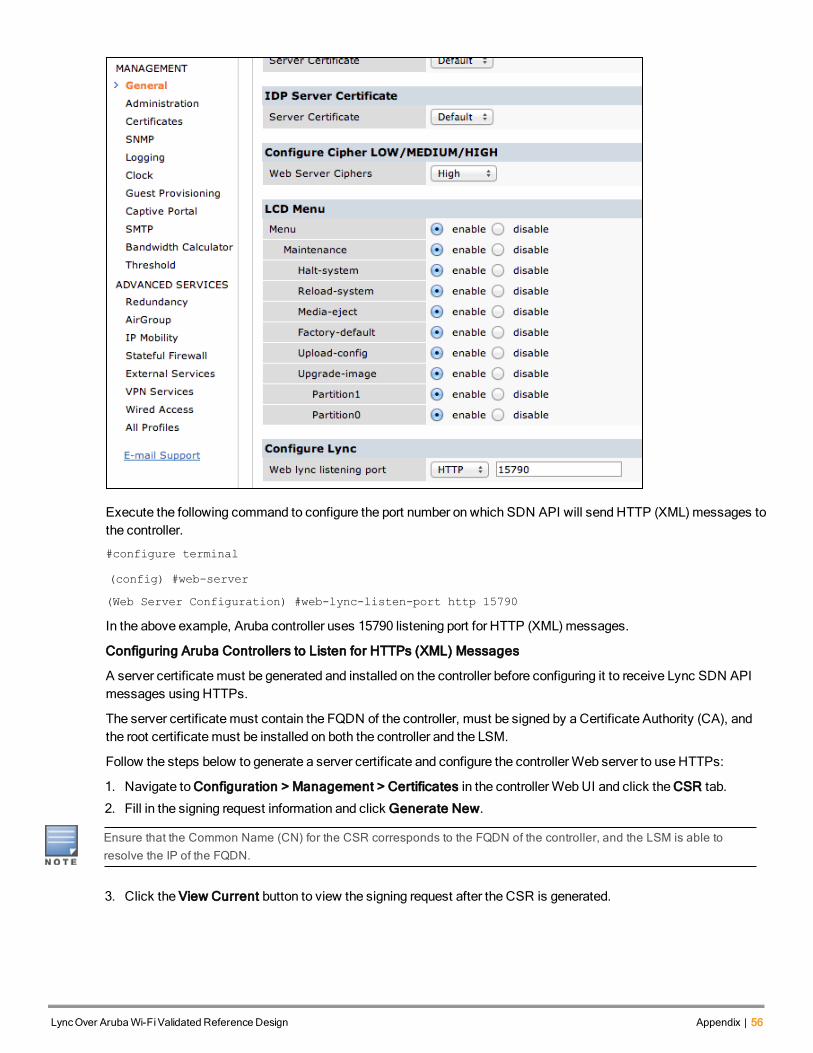
Execute the following command to configure the port number on which SDN API will send HTTP (XML)messages tothe controller.
#configure terminal
(config) #web-server
(Web Server Configuration) #web-lync-listen-port http 15790
In the above example, Aruba controller uses 15790 listening port for HTTP (XML)messages.
Configuring Aruba Controllers to Listen for HTTPs (XML) Messages
A server certificate must be generated and installed on the controller before configuring it to receive Lync SDN APImessages using HTTPs.
The server certificate must contain the FQDN of the controller, must be signed by a Certificate Authority (CA), andthe root certificate must be installed on both the controller and the LSM.
Follow the steps below to generate a server certificate and configure the controllerWeb server to use HTTPs:
1. Navigate to Configuration > Management > Certificates in the controllerWebUI and click the CSR tab.
2. Fill in the signing request information and click Generate New.
Ensure that the Common Name (CN) for the CSR corresponds to the FQDN of the controller, and the LSM is able toresolve the IP of the FQDN.
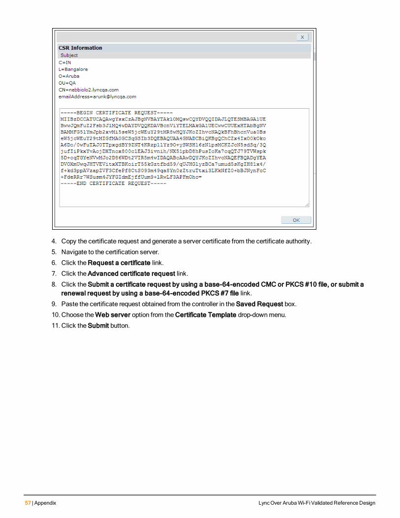
3. Click the View Current button to view the signing request after the CSR is generated.
LyncOver ArubaWi-FiValidated Reference Design Appendix | 56
57 | Appendix LyncOver ArubaWi-FiValidated Reference Design
4. Copy the certificate request and generate a server certificate from the certificate authority.
5. Navigate to the certification server.
6. Click the Request a certificate link.
7. Click the Advanced certificate request link.
8. Click the Submit a certificate request by using a base-64-encoded CMC or PKCS #10 file, or submit arenewal request by using a base-64-encoded PKCS #7 file link.
9. Paste the certificate request obtained from the controller in the Saved Request box.
10. Choose theWeb server option from the Certificate Template drop-downmenu.
11. Click the Submit button.
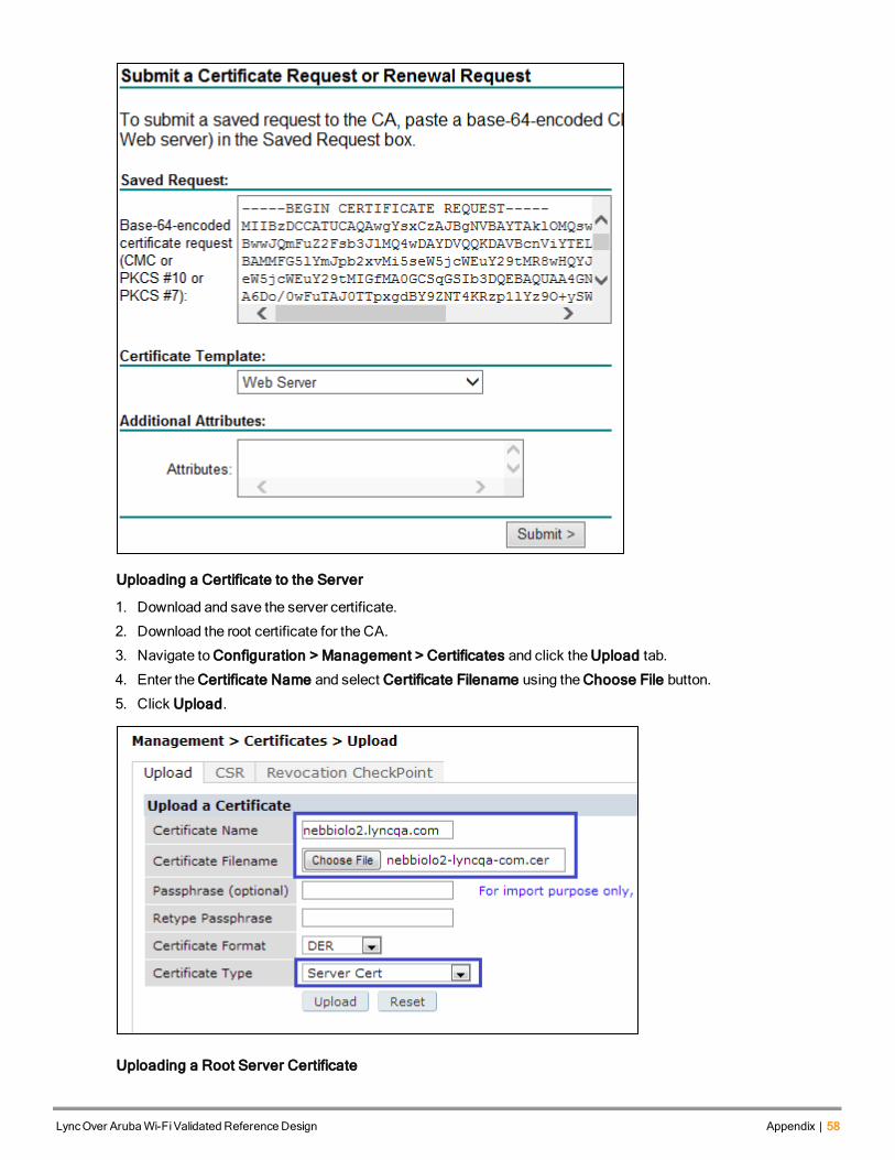
Uploading a Certificate to the Server
1. Download and save the server certificate.
2. Download the root certificate for the CA.
3. Navigate to Configuration > Management > Certificates and click the Upload tab.
4. Enter the Certificate Name and select Certificate Filename using the Choose File button.
5. Click Upload.
Uploading a Root Server Certificate
LyncOver ArubaWi-FiValidated Reference Design Appendix | 58
59 | Appendix LyncOver ArubaWi-FiValidated Reference Design
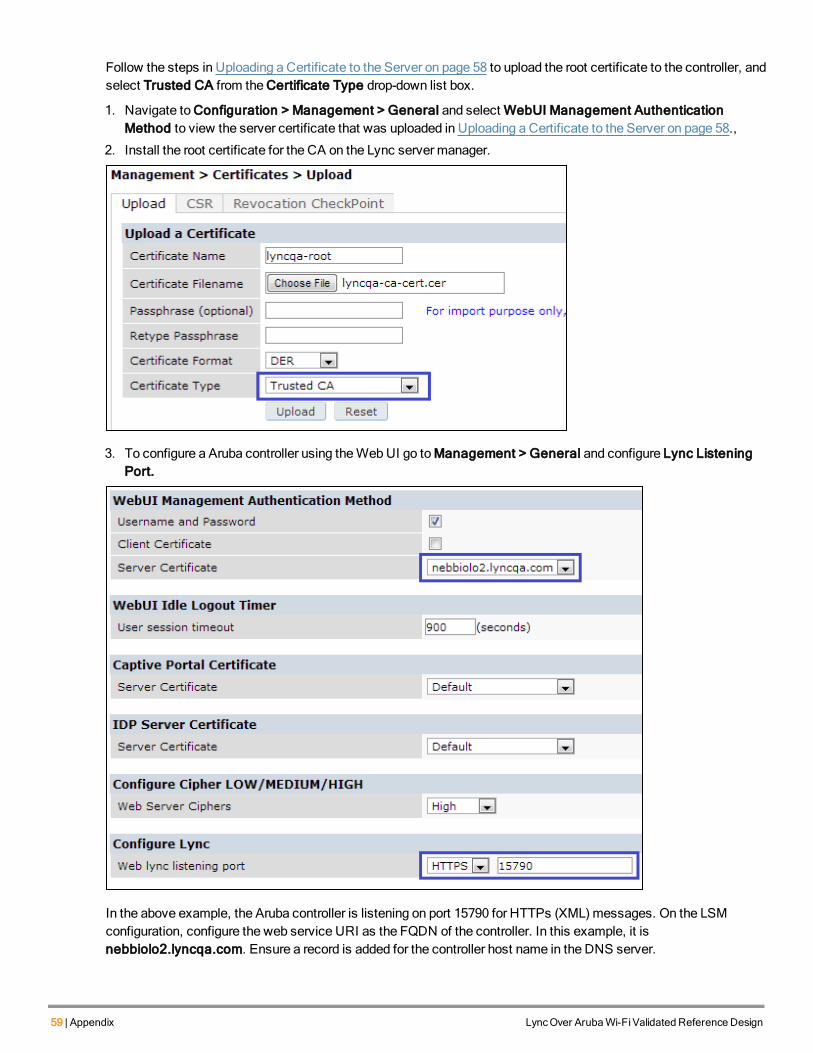
Follow the steps in Uploading a Certificate to the Server on page 58 to upload the root certificate to the controller, andselect Trusted CA from the Certificate Type drop-down list box.
1. Navigate to Configuration > Management > General and select WebUI Management AuthenticationMethod to view the server certificate that was uploaded in Uploading a Certificate to the Server on page 58.,
2. Install the root certificate for the CA on the Lync server manager.
3. To configure a Aruba controller using theWebUI go toManagement > General and configure Lync ListeningPort.
In the above example, the Aruba controller is listening on port 15790 for HTTPs (XML)messages. On the LSMconfiguration, configure the web service URI as the FQDN of the controller. In this example, it isnebbiolo2.lyncqa.com. Ensure a record is added for the controller host name in the DNS server.
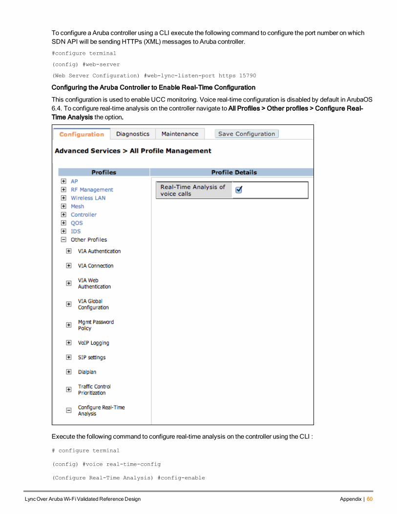
To configure a Aruba controller using a CLI execute the following command to configure the port number on whichSDN API will be sending HTTPs (XML)messages to Aruba controller.
#configure terminal
(config) #web-server
(Web Server Configuration) #web-lync-listen-port https 15790
Configuring the Aruba Controller to Enable Real-Time Configuration
This configuration is used to enable UCC monitoring. Voice real-time configuration is disabled by default in ArubaOS6.4. To configure real-time analysis on the controller navigate to All Profiles > Other profiles > Configure Real-Time Analysis the option.
Execute the following command to configure real-time analysis on the controller using the CLI :
# configure terminal
(config) #voice real-time-config
(Configure Real-Time Analysis) #config-enable
LyncOver ArubaWi-FiValidated Reference Design Appendix | 60
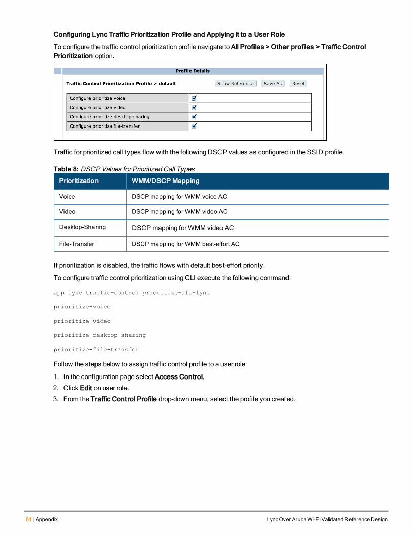
61 | Appendix LyncOver ArubaWi-FiValidated Reference Design
Configuring Lync Traffic Prioritization Profile and Applying it to a User Role
To configure the traffic control prioritization profile navigate to All Profiles > Other profiles > Traffic ControlPrioritization option.
Traffic for prioritized call types flow with the following DSCP values as configured in the SSID profile.
Prioritization WMM/DSCP Mapping
Voice DSCP mapping for WMM voice AC
Video DSCP mapping for WMM video AC
Desktop-Sharing DSCP mapping forWMM video AC
File-Transfer DSCP mapping for WMM best-effort AC
Table 8: DSCP Values for Prioritized Call Types
If prioritization is disabled, the traffic flows with default best-effort priority.
To configure traffic control prioritization using CLI execute the following command:
app lync traffic-control prioritize-all-lync
prioritize-voice
prioritize-video
prioritize-desktop-sharing
prioritize-file-transfer
Follow the steps below to assign traffic control profile to a user role:
1. In the configuration page select Access Control.
2. Click Edit on user role.
3. From the Traffic Control Profile drop-downmenu, select the profile you created.
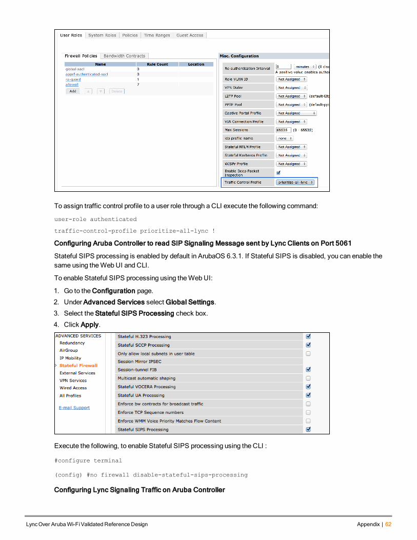
To assign traffic control profile to a user role through a CLI execute the following command:
user-role authenticated
traffic-control-profile prioritize-all-lync !
Configuring Aruba Controller to read SIP Signaling Message sent by Lync Clients on Port 5061
Stateful SIPS processing is enabled by default in ArubaOS 6.3.1. If Stateful SIPS is disabled, you can enable thesame using theWebUI and CLI.
To enable Stateful SIPS processing using theWebUI:
1. Go to the Configuration page.
2. Under Advanced Services select Global Settings.
3. Select the Stateful SIPS Processing check box.
4. Click Apply.
Execute the following, to enable Stateful SIPS processing using the CLI :
#configure terminal
(config) #no firewall disable-stateful-sips-processing
Configuring Lync Signaling Traffic on Aruba Controller
LyncOver ArubaWi-FiValidated Reference Design Appendix | 62

63 | Appendix LyncOver ArubaWi-FiValidated Reference Design
Ensure that Lync signaling traffic is permitted (TCP Port 5061) in Lync Access Control List (ACL). This ACL shouldbemapped to the user role to allow Lync signaling traffic. To view Lync ACL in theWebUI:
1. Click on the Configuration tab.
2. Select Security -> Firewall Policies.
The following example indicates Lync ACL assigned to a test user role.
netservice svc-sips tcp 5061 alg sips !
ip access-list session lync-acl
any any svc-sips permit queue high !
user-role test access-list session lync-acl
Configuration Specific to ArubaOS 6.3
Removing media-classification CLI from Aruba Controller: Heuristics based detection of Lync traffic is notcompatible with the API detectionmethod andmust be turned off. The Classify Media optionmust not be enabled inthe svc-sips ACL that is applied to the user role.
The following figure helps you determine if Classify Media is configured in an ip access-list session that isassociated to an user-role.
Executing the following CLI command helps in determining if Classify Media is configured in an ip access-listsession that is associated to a test user-role.
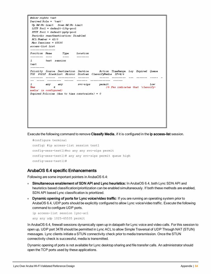
Execute the following command to remove Classify Media, if it is configured in the ip access-list session.
#configure terminal
config) #ip access-list session test1
config-sess-test1)#no any any svc-sips permit
config-sess-test1)# any any svc-sips permit queue high
config-sess-test1)#
ArubaOS 6.4 specific EnhancementsFollowing are some important pointers in ArubaOS 6.4:
l Simultaneous enablement of SDN API and Lync heuristics: In ArubaOS 6.4, both Lync SDN API andheuristics based classification/prioritization can be enabled simultaneously. If both thesemethods are enabled,SDN API based Lync classification is prioritized.
l Dynamic opening of ports for Lync voice/video traffic: If you are running an operating system prior toArubaOS 6.4, UDP ports should be explicitly configured to allow Lync voice/video traffic. Execute the followingcommand to configure UDP ports.ip access-list session lync-acl
any any udp 1025-65535 permit
In ArubaOS 6.4, firewall sessions dynamically open up in datapath for Lync voice and video calls. For this session toopen up, UDP port 3478 should be permitted in Lync ACL to allow Simple Traversal of UDP Through NAT (STUN)messages. Lync clients initiate a STUN connectivity check prior to media transmission. Once the STUNconnectivity check is successful, media is transmitted.
Dynamic opening of ports is not available for Lync desktop sharing and file transfer calls. An administrator shouldopen the TCP ports used by these applications.
LyncOver ArubaWi-FiValidated Reference Design Appendix | 64
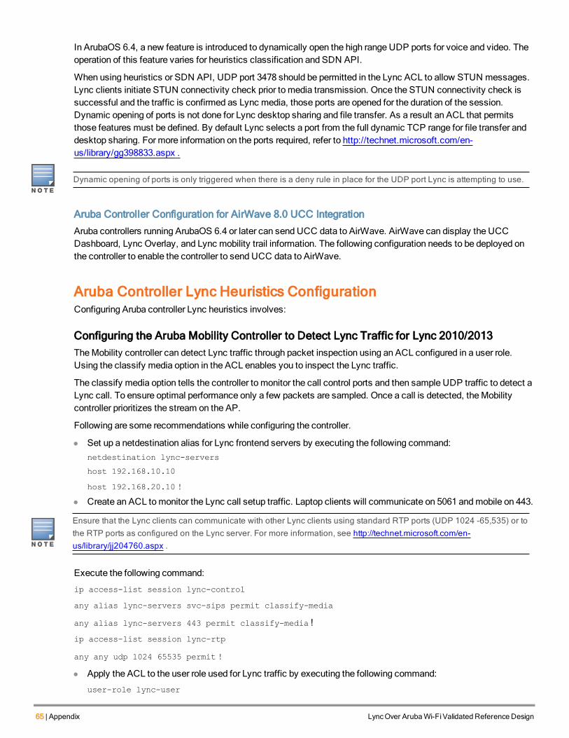
65 | Appendix LyncOver ArubaWi-FiValidated Reference Design
In ArubaOS 6.4, a new feature is introduced to dynamically open the high range UDP ports for voice and video. Theoperation of this feature varies for heuristics classification and SDN API.
When using heuristics or SDN API, UDP port 3478 should be permitted in the Lync ACL to allow STUN messages.Lync clients initiate STUN connectivity check prior to media transmission. Once the STUN connectivity check issuccessful and the traffic is confirmed as Lync media, those ports are opened for the duration of the session.Dynamic opening of ports is not done for Lync desktop sharing and file transfer. As a result an ACL that permitsthose features must be defined. By default Lync selects a port from the full dynamic TCP range for file transfer anddesktop sharing. For more information on the ports required, refer to http://technet.microsoft.com/en-us/library/gg398833.aspx .
Dynamic opening of ports is only triggered when there is a deny rule in place for the UDP port Lync is attempting to use.
Aruba Controller Configuration for AirWave 8.0 UCC Integration
Aruba controllers running ArubaOS 6.4 or later can send UCC data to AirWave. AirWave can display the UCCDashboard, Lync Overlay, and Lync mobility trail information. The following configuration needs to be deployed onthe controller to enable the controller to send UCC data to AirWave.
Aruba Controller Lync Heuristics ConfigurationConfiguring Aruba controller Lync heuristics involves:
Configuring the Aruba Mobility Controller to Detect Lync Traffic for Lync 2010/2013TheMobility controller can detect Lync traffic through packet inspection using an ACL configured in a user role.Using the classify media option in the ACL enables you to inspect the Lync traffic.
The classify media option tells the controller to monitor the call control ports and then sample UDP traffic to detect aLync call. To ensure optimal performance only a few packets are sampled. Once a call is detected, theMobilitycontroller prioritizes the stream on the AP.
Following are some recommendations while configuring the controller.
l Set up a netdestination alias for Lync frontend servers by executing the following command:netdestination lync-servers
host 192.168.10.10
host 192.168.20.10 !
l Create an ACL tomonitor the Lync call setup traffic. Laptop clients will communicate on 5061 andmobile on 443.
Ensure that the Lync clients can communicate with other Lync clients using standard RTP ports (UDP 1024 -65,535) or tothe RTP ports as configured on the Lync server. For more information, see http://technet.microsoft.com/en-us/library/jj204760.aspx .
Execute the following command:
ip access-list session lync-control
any alias lync-servers svc-sips permit classify-media
any alias lync-servers 443 permit classify-media !
ip access-list session lync-rtp
any any udp 1024 65535 permit !
l Apply the ACL to the user role used for Lync traffic by executing the following command:
user-role lync-user

access-list session lync-control
access-list session lync-rtp
Administrators must configure an ACL to allow TCP based non-RTP Lync traffic such as desktop sharing and file transfer.This traffic is not prioritized by heuristics, but ACL ensures that the traffic is not blocked.
Configuring the Aruba Mobility Controller to Detect Lync TrafficClients that connect to Microsoft Office 365 for Lync use Port 443 to send call control to the Lync servers. As only asmall number of packets are inspected, applying the ACL has minimal impact on the controller even though all httpssessions are inspected. Listed below are a few recommendations to be followed while configuring a controller.
l Create an ACL tomonitor the Lync call setup by executing the following command:ip access-list session lync-365-contro
any any tcp 443 permit classify-media
!ip access-list session lync-rtp
any any udp 1024 65535 permit
!
l Apply the ACL to the user role used for Lync traffic by executing the following command:user-role lync-user
access-list session lync-365-controlaccess-list session lync-rtp
Verifying Operation of Heuristics Detection of Lync TrafficOnce heuristics detection is configured on theMobility controller and users are assigned with roles the Lyncdetection ACL, theMobility controller begins to identify and prioritize the Lync traffic.
Additional commands to monitor Lync traffic via the SDN API were introduced from ArubaOS 6.3. When using heuristicsthese commands do not display Lync call or client information.
To verify the operation of the heuristics detection start a Lync call between two clients and then log into theMobilitycontroller via the command line. Run the following commands to verify heuristic detection.
show datapath session table <IP-of-Lync-Client>
Ensure that the traffic between the two clients has the V flag set.
show voice call-cdrs
LyncOver ArubaWi-FiValidated Reference Design Appendix | 66
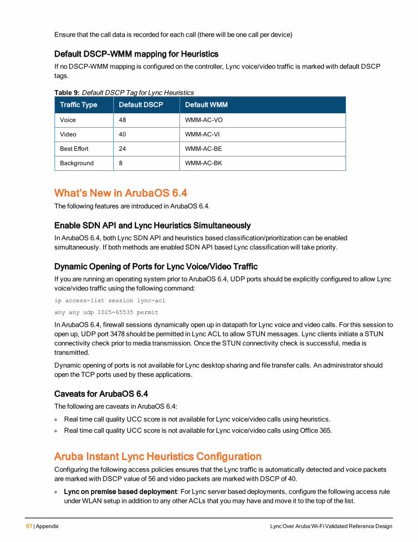
67 | Appendix LyncOver ArubaWi-FiValidated Reference Design
Ensure that the call data is recorded for each call (there will be one call per device)
Default DSCP-WMM mapping for HeuristicsIf no DSCP-WMMmapping is configured on the controller, Lync voice/video traffic is marked with default DSCPtags.
Traffic Type Default DSCP Default WMM
Voice 48 WMM-AC-VO
Video 40 WMM-AC-VI
Best Effort 24 WMM-AC-BE
Background 8 WMM-AC-BK
Table 9: Default DSCP Tag for Lync Heuristics
What’s New in ArubaOS 6.4The following features are introduced in ArubaOS 6.4.
Enable SDN API and Lync Heuristics SimultaneouslyIn ArubaOS 6.4, both Lync SDN API and heuristics based classification/prioritization can be enabledsimultaneously. If bothmethods are enabled SDN API based Lync classification will take priority.
Dynamic Opening of Ports for Lync Voice/Video TrafficIf you are running an operating system prior to ArubaOS 6.4, UDP ports should be explicitly configured to allow Lyncvoice/video traffic using the following command:
ip access-list session lync-acl
any any udp 1025-65535 permit
In ArubaOS 6.4, firewall sessions dynamically open up in datapath for Lync voice and video calls. For this session toopen up, UDP port 3478 should be permitted in Lync ACL to allow STUN messages. Lync clients initiate a STUNconnectivity check prior to media transmission. Once the STUN connectivity check is successful, media istransmitted.
Dynamic opening of ports is not available for Lync desktop sharing and file transfer calls. An administrator shouldopen the TCP ports used by these applications.
Caveats for ArubaOS 6.4The following are caveats in ArubaOS 6.4:
l Real time call quality UCC score is not available for Lync voice/video calls using heuristics.
l Real time call quality UCC score is not available for Lync voice/video calls using Office 365.
Aruba Instant Lync Heuristics ConfigurationConfiguring the following access policies ensures that the Lync traffic is automatically detected and voice packetsaremarked with DSCP value of 56 and video packets aremarked with DSCP of 40.
l Lync on premise based deployment: For Lync server based deployments, configure the following access ruleunderWLAN setup in addition to any other ACLs that youmay have andmove it to the top of the list.
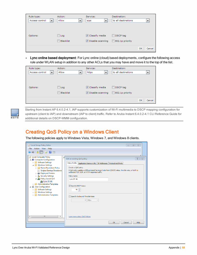
l Lync online based deployment: For Lync online (cloud) based deployments, configure the following accessrule underWLAN setup in addition to any other ACLs that youmay have andmove it to the top of the list.
Starting from Instant AP 6.4.0.2-4.1, IAP supports customization of Wi-Fi multimedia to DSCP mapping configuration forupstream (client to IAP) and downstream (IAP to client) traffic. Refer to Aruba Instant 6.4.0.2-4.1 CLI Reference Guide foradditional details on DSCP-WMM configuration.
Creating QoS Policy on a Windows ClientThe following policies apply toWindows Vista, Windows 7, andWindows 8 clients.
LyncOver ArubaWi-FiValidated Reference Design Appendix | 68
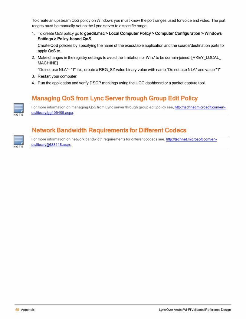
69 | Appendix LyncOver ArubaWi-FiValidated Reference Design
To create an upstream QoS policy onWindows youmust know the port ranges used for voice and video. The portranges must bemanually set on the Lync server to a specific range.
1. To create QoS policy go to gpedit.msc > Local Computer Policy > Computer Configuration > WindowsSettings > Policy-based QoS.
Create QoS policies by specifying the name of the executable application and the source/destination ports toapply QoS to.
2. Make changes in the registry settings to avoid the limitation forWin7 to be domain-joined: [HKEY_LOCAL_MACHINE]
"Do not use NLA"="1" i.e., create a REG_SZ value binary value with name "Do not use NLA" and value "1"
3. Restart your computer.
4. Run the application and verify DSCP markings using the UCC dashboard or a packet capture tool.
Managing QoS from Lync Server through Group Edit PolicyFor more information on managing QoS from Lync server through group edit policy see, http://technet.microsoft.com/en-us/library/gg405409.aspx.
Network Bandwidth Requirements for Different CodecsFor more information on network bandwidth requirements for different codecs see, http://technet.microsoft.com/en-us/library/jj688118.aspx.