LYCOMING OPERATOR’S MANUAL SECTION 5...
16
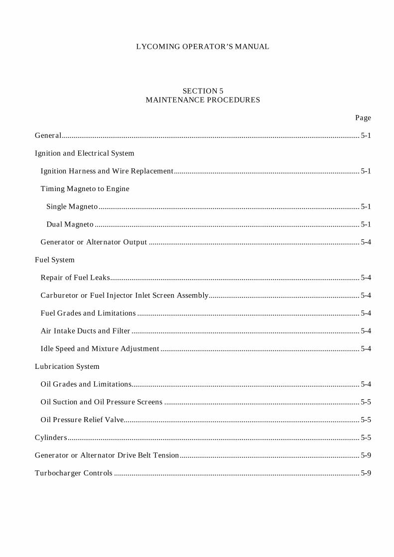
LYCOMING OPERATOR’S MANUAL SECTION 5 MAINTENANCE PROCEDURES Page General .......................................................................................................................................................... 5-1 Ignition and Electrical System Ignition Harness and Wire Replacement................................................................................................ 5-1 Timing Magneto to Engine Single Magneto ....................................................................................................................................... 5-1 Dual Magneto ......................................................................................................................................... 5-1 Generator or Alternator Output ............................................................................................................. 5-4 Fuel System Repair of Fuel Leaks ................................................................................................................................. 5-4 Carburetor or Fuel Injector Inlet Screen Assembly.............................................................................. 5-4 Fuel Grades and Limitations ................................................................................................................... 5-4 Air Intake Ducts and Filter ...................................................................................................................... 5-4 Idle Speed and Mixture Adjustment ....................................................................................................... 5-4 Lubrication System Oil Grades and Limitations...................................................................................................................... 5-4 Oil Suction and Oil Pressure Screens ..................................................................................................... 5-5 Oil Pressure Relief Valve.......................................................................................................................... 5-5 Cylinders ....................................................................................................................................................... 5-5 Generator or Alternator Drive Belt Tension ............................................................................................. 5-9 Turbocharger Controls ............................................................................................................................... 5-9
Transcript of LYCOMING OPERATOR’S MANUAL SECTION 5...
LYCOMING OPERATOR’S MANUAL
SECTION 5MAINTENANCE PROCEDURES
Page
General.......................................................................................................................................................... 5-1
Ignition and Electrical System
Ignition Harness and Wire Replacement................................................................................................ 5-1
Timing Magneto to Engine
Single Magneto ....................................................................................................................................... 5-1
Dual Magneto ......................................................................................................................................... 5-1
Generator or Alternator Output ............................................................................................................. 5-4
Fuel System
Repair of Fuel Leaks................................................................................................................................. 5-4
Carburetor or Fuel Injector Inlet Screen Assembly.............................................................................. 5-4
Fuel Grades and Limitations ................................................................................................................... 5-4
Air Intake Ducts and Filter...................................................................................................................... 5-4
Idle Speed and Mixture Adjustment ....................................................................................................... 5-4
Lubrication System
Oil Grades and Limitations...................................................................................................................... 5-4
Oil Suction and Oil Pressure Screens ..................................................................................................... 5-5
Oil Pressure Relief Valve.......................................................................................................................... 5-5
Cylinders....................................................................................................................................................... 5-5
Generator or Alternator Drive Belt Tension............................................................................................. 5-9
Turbocharger Controls ............................................................................................................................... 5-9

This Page Intentionally Left Blank

LYCOMING OPERATOR’S MANUAL SECTION 5O-360 AND ASSOCIATED MODELS MAINTENANCE PROCEDURES
SECTION 5
MAINTENANCE PROCEDURES
The procedures described in this section are provided to guide and instruct personnel in performing suchmaintenance operations that may be required in conjunction with the periodic inspections listed in thepreceding section. No attempt is made to include repair and replacement operations that will be found in theapplicable Lycoming Overhaul Manual.
1. IGNITION AND ELECTRICAL SYSTEM.
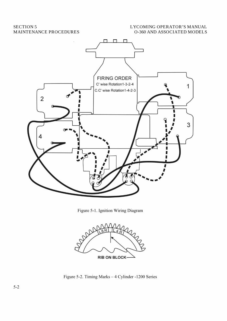
a. Ignition Harness and Wire Replacement – In the event that an ignition harness or an individual lead isto be replaced, consult the wiring diagram to be sure harness is correctly installed. Marklocation ofclamps and clips to be certain the replacement is clamped at correct locations.
b. Timing Magnetos to Engine.
(1) Remove a sparkplug from No. 1 cylinder and place a thumb over the sparkplug hole. Rotate thecrankshaft in direction of normal rotation until the compression stroke is reached, this is indicatedby a positive pressure inside the cylinder tending to push the thumb off the spark plug hole.Continue rotating the crankshaft until the advance timing markon the front face of the starter ringgear is in alignment with the small hole located at the two o�clockposition on the front face ofthe starter housing. (Ring gear may be marked at 20°and 25°. Consult specifications for correcttiming markof your installation.) At this point, the engine is ready for assembly of the magnetos.
(2) Single Magneto – Remove the inspection plugs from both magnetos and turn the drive shaft indirection of normal rotation until (-20 and -200 series) the first painted chamfered tooth on thedistributor gear is aligned in the center of the inspection window;(-1200 series) the applicabletiming mark on the distributor gear is approximately aligned with the markon the distributorblock. See Figure 5-2. Being sure the gear does not move from this position, install gaskets andmagnetos on the engine. Note that an adapter is used with impulse coupling magneto. Securewith (clamps on -1200 series) washers and nuts;tighten only finger tight.
(3) Using a battery powered timing light, attach the positive lead to a suitable terminal connected tothe switch terminal of the magneto and the negative lead to any unpainted portion of the engine.Rotate the magneto in its mounting flange to a point where the light comes on, then slowly turn itin the opposite direction until the light goes out. Bring the magneto backslowly until the lightjust comes on. Repeat this with the second magneto.
(4) Back off the crankshaft a few degrees, the timing lights should go out. Bring the crankshaftslowly back in direction of normal rotation until the timing mark and the hole in the starterhousing are in alignment. At this point, both lights should go on simultaneously. Tighten nuts tospecified torque.
(5) Dual Magnetos – Remove the timing window plug from the most convenient side of the housingand the plug from the rotor viewing location in the center of the housing.
(6) Turn the rotating magnet drive shaft in direction of normal rotation until the painted tooth of thedistributor gear is center in the timing hole. Observe that at this time the built in pointer justahead of the rotor viewing window aligns with either the L or R (depending on rotation).
5-1
SECTION 5 LYCOMING OPERATOR’S MANUALMAINTENANCE PROCEDURES O-360 AND ASSOCIATED MODELS
Figure 5-1. Ignition Wiring Diagram
Figure 5-2. Timing Marks � 4 Cylinder -1200 Series
5-2
LYCOMING OPERATOR’S MANUAL SECTION 5O-360 AND ASSOCIATED MODELS MAINTENANCE PROCEDURES
(7) Hold the magneto in this position and install gasket and magnetos. Secure with clamps, washersand nuts tightened only finger tight.
(8) Using a battery powered timing light, attach one positive lead to left switch terminal, one positivelead to right switch terminal and the ground lead to the magneto housing.
(9) Turn the entire magneto in direction of rotation until the timing light comes on, then slowly turnit in the opposite direction until the light goes out. Bring the magneto backslowly until the lightjust comes on.
(10) Back off the crankshaft a few degrees, the timing lights should go out. Bring the crankshaftslowly backin direction of normal rotation until the lights just come on. Both lights should go on2°of No. 1 engine firing position.
NOTE
Some timing lights operate in the reverse manner as described. The light comes on when thebreaker points open. Check your timing light instructions.
c. Internal Timing – Dual Magneto – Checkthe magneto internal timing and breaker synchronization inthe following manner.
(1) Main Breakers – Connect the timing light negative lead to any unpainted surface of the magneto.Connect one positive lead to the left main breaker terminal and the second positive lead to theright main breaker terminal.
(2) Backthe engine up a few degrees and again bump forward toward number one cylinder firingposition while observing timing lights. Both lights should go out to indicate opening of the mainbreakers when the timing pointer is indicating within the width of the �L� or �R� mark. If breaker timing is incorrect, loosen breaker screws and correct. Retorque breaker screws to 20-25 in.-lbs.
(3) Retard Breaker – Remove timing light leads from the main breaker terminals. Attach onepositive lead to retard breaker terminal, and second positive lead to the tachometer breakerterminal, if used.
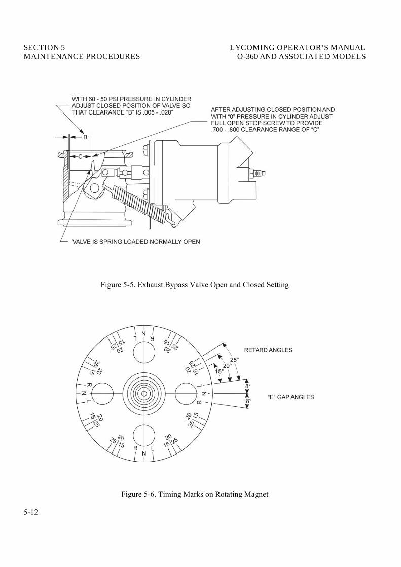
(4) Backthe engine up a few degrees and again bump forward toward number one cylinder firingposition until pointer is aligned with 15°retard timing mark. See Figure 5-6. Retard breakershould just open at this position.
(5) If retard timing is not correct, loosen cam securing screw and turn the retard breaker cam asrequired to make retard breaker open per paragraph c (4). Retorque cam screw to 16-20 in.-lbs.
(6) Observe the tachometer breaker is opened by the cam lobe. No synchronization of this breaker isrequired.
(7) Check action of impulse coupling (D-2000/3000 series only). With the ignition switch offobserve breaker cam end of rotor while manually cranking engine through a firing sequence.Rotor should alternately stop and then (with an audible snap) be rotated rapidly through a retardfiring position.
5-3
SECTION 5 LYCOMING OPERATOR’S MANUALMAINTENANCE PROCEDURES O-360 AND ASSOCIATED MODELS
d. Generator or Alternator Output – The generator or alternator (whichever is applicable) should bechecked to determine that the specified voltage and current are being obtained.
2. FUEL SYSTEM.
a. Repair of Fuel Leaks – In the event a line or fitting in the fuel system is replaced, only a fuel solublelubricant such as clean engine oil or Loctite Hydraulic Sealant may be used on tapered threads. Do notuse Teflon tape or any other form of thread compound. Do not apply sealant to the first two threads.
b. Carburetor or Fuel Injector (Except Simmonds Injectors) Fuel Inlet Screen Assembly – Remove theassembly and checkthe screen for distortion or openings in the strainer. Replace for either of theseconditions. Clean screen assembly in solvent and dry with compressed air and reinstall. The fuel inletscreen assembly is tightened to 35-40 in.-lbs. on carburetors and 65-70 in.-lbs. on fuel injectors. Thehexhead plug on pressure carburetor is tightened to 160-175 in.-lbs.
c. Fuel Grade and Limitations – The recommended aviation grade fuel for the subject engines is listed inSection 3, Item 8.
In the event that the specified fuel is not available at some locations, it is permissible to use higheroctane fuel. Fuel of a lower octane than specified is not to be used. Under no circumstances shouldautomotive fuel be used (regardless of octane rating).
NOTE
It is recommended that personnel be familiar with latest revision of Service Instruction No.1070 regarding specified fuel for Lycoming engines.
d. Air Intake Ducts and Filter – Checkall air intake ducts for dirt or restrictions. Inspect and service airfilters as instructed in the airframe manufacturer�s handbook.
e. Idle Speed and Mixture Adjustment.
(1) Start the engine and warm up in the usual manner until oil and cylinder head temperatures arenormal.
(2) Check magnetos. If the �mag-drop� is normal, proceed with idle adjustment.
(3) Set throttle stop screw so that the engine idles at the airframe manufacturer�s recommended idling RPM. If the RPM changes appreciably after making idle mixture adjustment during thesucceeding steps, readjust the idle speed to the desired RPM.
(4) When the idling speed has been stabilized, move the cockpit mixture control lever with a smooth,steady pull toward the �Idle Cut-Off� position and observe the tachometer for any change duringthe leaning process. Caution must be exercised to return the mixture control to the �Full Rich� position before the RPM can drop to a point where the engine cuts out. An increase of more than50 RPM while �leaning out� indicates an excessively rich idle mixture. An immediate decrease inRPM (if not preceded by a momentary increase) indicates the idle mixture is too lean.
5-4
LYCOMING OPERATOR’S MANUAL SECTION 5O-360 AND ASSOCIATED MODELS MAINTENANCE PROCEDURES
If step (4) indicates that the idle adjustment is too rich or too lean, turn the idle mixtureadjustment in direction required for correction, and checkthis new position by repeating the aboveprocedure. Make additional adjustments as necessary until a checkresults in a momentary pick-upof approximately 50 RPM. Each time the adjustment is changed, the engine should be run up to2000 RPM to clean the engine before proceeding with the RPM check. Make final adjustment ofthe idle speed adjustment to obtain the desired idling RPM with closed throttle. The above methodaims at a setting that will obtain maximum RPM with minimum manifold pressure. In case thesetting does not remain stable, checkthe idle linkage;any looseness in this linkage would causeerratic idling. In all cases, allowance should be made for the effect of weather conditions and fieldaltitude upon idling adjustment.
3. LUBRICATION SYSTEM.
a. Oil Grades and Limitations – Service the engine in accordance with the recommended grade oil asspecified in Section 3, Item 8.
b. Oil Suction and Oil Pressure Screens – At each 100-hour inspection remove suction screen. Inspectfor metal particles;clean and reinstall. Inspect and clean pressure screen every 25 hours.
c. Oil Pressure Relief Valve – Subject engines may be equipped with either an adjustable or non-adjustable oil pressure relief valve. A brief description of both types follows:
(1) Non-Adjustable Oil Pressure Relief Valve – The function of the oil pressure relief valve is tomaintain engine oil pressure within specified limits. The valve, although not adjustable, maycontrol the oil pressure with the addition of a maximum of nine (9) P/N STD-425 washersbetween the cap and spring to increase the pressure. Removal of the washers will decrease the oilpressure. Some early model engines use a maximum of three (3) P/N STD-425 washers toincrease the oil pressure and the use of a P/N 73629 or P/N 73630 spacer between the cap andcrankcase to decrease the oil pressure. Particles of metal or other foreign matter lodged betweenthe ball and seal will result in faulty readings. It is advisable, therefore, to disassemble, inspectand clean the valve if excessive pressure fluctuations are noted.
(2) Oil Pressure Relief Valve (Adjustable) – The adjustable oil relief valve enables the operator tomaintain engine oil pressure within the specified limits. If pressure under normal operatingconditions should consistently exceed the maximum or minimum specified limits, adjust thevalve as follows:
With the engine warmed up and running at approximately 2000 RPM, observe the reading onthe oil pressure gage. If the pressure is above maximum or below minimum specified limits, stopengine and screw the adjusting screw outward to decrease pressure or inward to increasepressure. Depending on installation, the adjusting screw may have only a screw driver slot and isturned with a screw driver;or may have the screw driver slot plus a pinned .375-24 castellatednut and may be turned with either a screw driver or a boxwrench.
4. CYLINDERS. It is recommended that as a field operation, cylinder maintenance be confined toreplacement of the entire assembly. For valve replacement, consult the proper overhaul manual. This shouldbe undertaken only as an emergency measure.
5-5
SECTION 5 LYCOMING OPERATOR’S MANUALMAINTENANCE PROCEDURES O-360 AND ASSOCIATED MODELS
a. Removal of Cylinder Assembly.
(1) Remove exhaust manifold.
(2) Remove rocker box drain tube, intake pipe, baffle and any clips that might interfere with theremoval of the cylinder.
(3) Disconnect ignition cables and remove the bottom sparkplug.
(4) Remove rocker boxcover and rotate crankshaft until piston is approximately at top center of thecompression stroke. This is indicated by a positive pressure inside of cylinder tending to pushthumb off of bottom sparkplug hole.
(5) Slide valve rocker shafts from cylinder head and remove the valve rockers. Valve rocker shaftscan be removed when the cylinder is removed from the engine. Remove rotator cap from exhaustvalve stem.
(6) Remove push rods by grasping ball end and pulling rod out of shroud tube. Detach shroud tubespring and lockplate and pull shroud tubes through holes in cylinder head.
NOTE
The hydraulic tappets, push rods, rocker arms and valves must be assembled in the samelocation from which they were removed.
(7) Remove cylinder base nuts and hold down plates (where employed) then remove cylinder bypulling directly away from crankcase. Be careful not to allow the piston to drop against thecrankcase, as the piston leaves the cylinder.
b. Removal of Piston from Connecting Rod – Remove the piston pin plugs. Insert piston pin pullerthrough piston pin, assemble puller nut;then proceed to remove piston pin. Do not allow connectingrod to rest on the cylinder bore of the crankcase. Support the connecting rod with heavy rubber band,discarded cylinder base oil ring seal, or any other non-marring method.
c. Removal of Hydraulic Tappet Sockets and Plunger Assemblies – It will be necessary to remove andbleed the hydraulic tappet plunger assembly so that dry tappet clearance can be checked when thecylinder assembly is reinstalled. This is accomplished in the following manner:
(1) Remove the hydraulic tappet push rod socket by inserting the forefinger into the concave end ofthe socket and withdrawing. If the socket cannot be removed in this manner, it may be removedby grasping the edge of the socket with a pair of needle nose pliers. However, care must beexercised to avoid scratching the socket.
(2) To remove the hydraulic tappet plunger assembly, use the special Lycoming service tool. In theevent the tool is not available, the hydraulic tappet plunger assembly may be removed by a hookin the end of a short piece of lockwire, inserting the wire so that the hookengages the spring ofthe plunger assembly. Draw the plunger assembly out of the tappet body by gently pulling thewire.
5-6

LYCOMING OPERATOR’S MANUAL SECTION 5O-360 AND ASSOCIATED MODELS MAINTENANCE PROCEDURES
CAUTION
NEVER USE A MAGNET TO REMOVE HYDRAULIC PLUNGER ASSEMBLIES FROMTHE CRANKCASE. THIS CAN CAUSE THE CHECK BALL TO REMAIN OFF ITS SEAT,RENDERING THE UNIT INOPERATIVE.
d. Assembly of Hydraulic Tappet Plunger Assemblies – To assemble the unit, unseat the ball by insertinga thin clean wire through the oil inlet hole. With the ball off its seat, insert the plunger and twistclockwise so that the spring catches. All oil must be removed before the plunger is inserted.
e. Assembly of Cylinder and Related Parts – Rotate the crankshaft so that the connecting rod of thecylinder being assembled is at the top center of compression stroke. This can be checked by placingtwo fingers on the intake and exhaust tappet bodies. Rockcrankshaft backand forth over top center. Ifthe tappet bodies do not move the crankshaft is on the compression stroke.
(1) Place each plunger assembly in its respective tappet body and assemble the socket on top ofplunger assembly.
(2) Assemble piston with rings so that the number stamped on the piston pin boss is toward the frontof the engine. The piston pin should be a handpush fit. If difficulty is experienced in inserting thepiston pin, it is probably caused by carbon or burrs in the piston pin hole. During assembly,always use a generous quantity of oil, both in the piston hole and on the piston pin.
(3) Assemble one piston pin plug at each end of the piston pin and place a new rubber oil seal ringaround the cylinder skirt. Coat piston and rings and the inside of the cylinder generously with oil.
(4) Using a piston ring compressor, assemble the cylinder over the piston so that the intake port is atthe bottom of the engine. Push the cylinder all the way on, catching the ring compressor as it ispushed off.
NOTE
Before installing cylinder hold-down nuts, lubricate crankcase thru-stud threads with anyone of the following lubricants, or combination of lubricants1. 90% SAE 50W engine oil and 10% STP.2. Parker Thread Lube.3. 60% SAE 30 engine oil and 40% Parker Thread Lube.
(5) Assemble hold-down plates (where applicable) and cylinder base hold-down nuts and tighten asdirected in the following steps.
NOTE
At any time a cylinder is replaced, it is necessary to retorque the thru-studs on the cylinderon the opposite side of the engine.
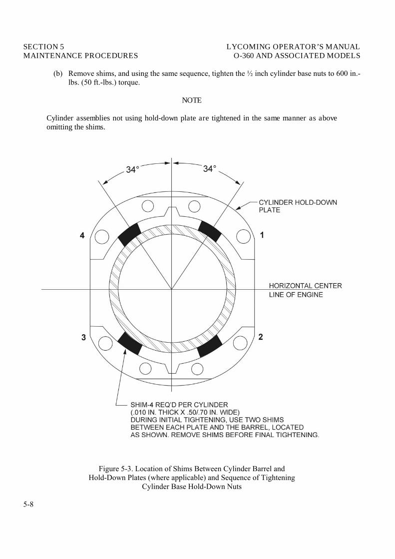
(a) (Engines using hold-down plates) – Install shims between cylinder base hold-down plates andcylinder barrel, as directed in Figure 5-3, and tighten ½ inch hold-down nuts to 300 in.-lbs.(25 ft.-lbs.) torque, using the sequence shown in Figure 5-3.
5-7
SECTION 5 LYCOMING OPERATOR’S MANUALMAINTENANCE PROCEDURES O-360 AND ASSOCIATED MODELS
(b) Remove shims, and using the same sequence, tighten the ½ inch cylinder base nuts to 600 in.-lbs. (50 ft.-lbs.) torque.
NOTE
Cylinder assemblies not using hold-down plate are tightened in the same manner as aboveomitting the shims.
Figure 5-3. Location of Shims Between Cylinder Barrel andHold-Down Plates (where applicable) and Sequence of Tightening
Cylinder Base Hold-Down Nuts
5-8
LYCOMING OPERATOR’S MANUAL SECTION 5O-360 AND ASSOCIATED MODELS MAINTENANCE PROCEDURES
(c) Tighten the inch hold-down nuts to 300 in.-lbs. (25 ft.-lbs.) torque. Sequence of tighteningis optional.
(d) As a final check, hold the torque wrench on each nut for about five seconds. If the nut doesnot turn, it may be presumed to be tightened to correct torque.
CAUTION
AFTER ALL CYLINDER BASE NUTS HAVE BEEN TIGHTENED, REMOVE ANY NICKS INTHE CYLINDER FINS BY FILING OR BURRING.
(6) Install new shroud tube oil seals on both ends of shroud tube. Install shroud tube and lockinplace as required for type of cylinder.
(7) Assemble each push rod in its respective shroud tube, and assemble each rocker in its respectiveposition by placing rocker between bosses and sliding valve rocker shaft in place to retain rocker.Before installing exhaust valve rocker, place rotator cap over end of exhaust valve stem.
(8) Be sure that the piston is at top center of compression stroke and that both valves are closed.Checkclearance between the valve stem tip and the valve rocker. In order to checkthis clearance,place the thumb of one hand on the valve rocker directly over the end of the push rod and pushdown so as to compress the hydraulic tappet spring. While holding the spring compressed, thevalve clearance should be between .028and .080 inch. If clearance does not come within theselimits, remove the push rod and insert a longer or shorter push rod, as required, to correctclearance.
NOTE
Inserting a longer push rod will decrease the valve clearance.
(9) Install intercylinder baffles, rocker boxcovers, intake pipes, rocker boxdrain tubes and exhaustmanifold.
5. GENERATOR OR ALTERNATOR DRIVE BELT TENSION.
Checkthe tension of a new belt 25 hours after installation. Refer to latest revision of Service InstructionNo. 1129 and latest revision of Service Letter No. L160 for methods of checking generator or alternatordrive belt tension.
6. TURBOCHARGER CONTROLS.
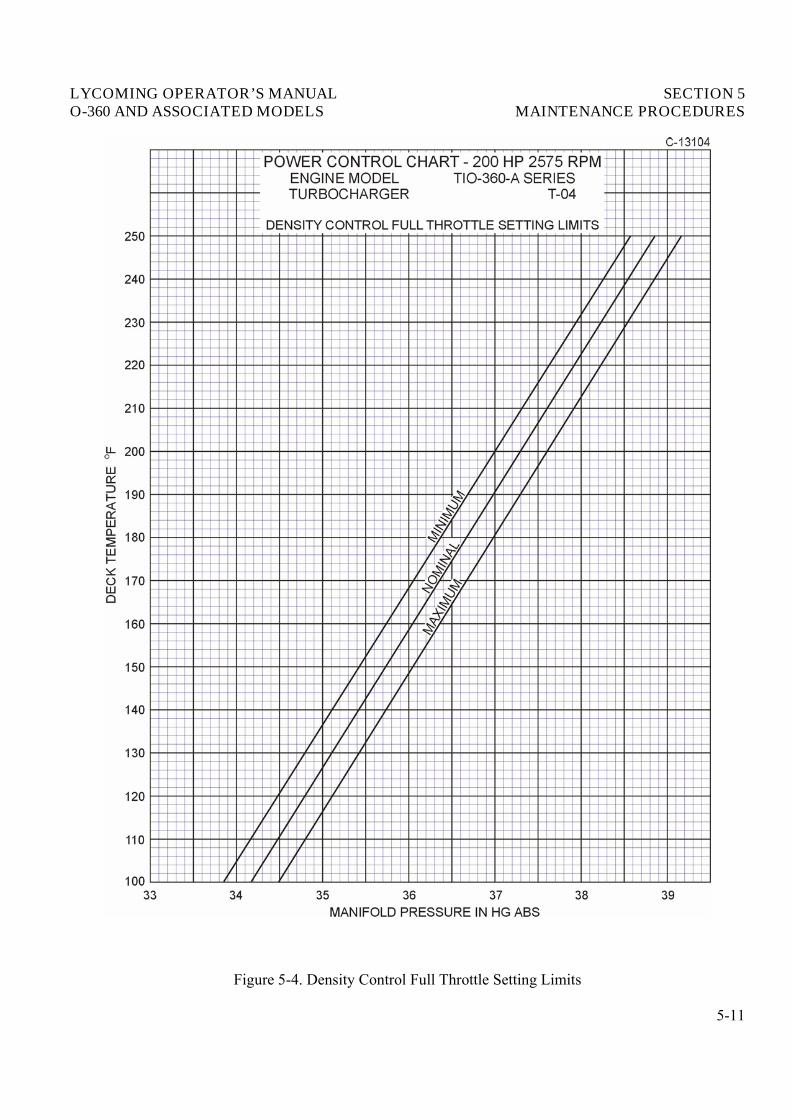
a. Density Controller – The density controller is adjusted at the factory to maintain a predeterminedconstant for desired horsepower.
The density controller is set to the curve, see Figure 5-4, under the following conditions: Enginestabilized at operating conditions, full throttle with oil pressure at 80 psi ±5 psi.
If it is suspected that the manifold pressure is not within limits, it may be checked to the curve.
EXAMPLE
Operating at the stated conditions with a compressor discharge temperature of 120°F, themanifold pressure should be 34.8 in. Hg. ± .3 in. Hg.
5-9

SECTON 5 LYCOMING OPERATOR’S MANUALMAINTENANCE PROCEDURES O-360 AND ASSOCIATED MODELS
If the manifold pressure is found to be out of limits, the cause might be found either in the densitycontroller, the differential pressure controller, or the waste gate. It is recommended that an authorizedoverhaul facility checkthese controls.
Exhaust Bypass Valve (TIO-360-A Series).
This valve is actuated by engine oil pressure and is set to predetermined open and closed clearances.These clearances and the procedures for setting them are shown in Figure 5-5.
Exhaust Bypass Valve (TIO-360-C1A6D).
This valve is mechanically controlled by a flexible linkage connected to the injector throttle arm and thewastegate control arm.
Adjust linkage as follows:
(1) Move injector throttle arm to full open position.
(2) Insert a .005-.015 inch feeler gage between the bypass butterfly valve, in the closed position, andthe bypass housing.
(3) Adjust linkage until the bypass valve control arm is at the full closed stop position.
5-10
LYCOMING OPERATOR’S MANUAL SECTION 5O-360 AND ASSOCIATED MODELS MAINTENANCE PROCEDURES
Figure 5-4. Density Control Full Throttle Setting Limits
5-11
SECTION 5 LYCOMING OPERATOR’S MANUALMAINTENANCE PROCEDURES O-360 AND ASSOCIATED MODELS
Figure 5-5. Exhaust Bypass Valve Open and Closed Setting
Figure 5-6. Timing Marks on Rotating Magnet
5-12
LYCOMING OPERATOR’S MANUAL SECTION 5O-360 AND ASSOCIATED MODELS MAINTENANCE PROCEDURES
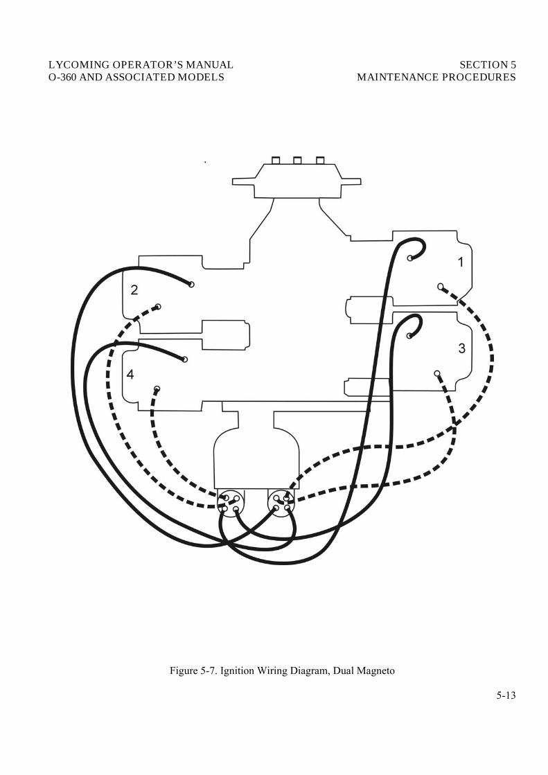
Figure 5-7. Ignition Wiring Diagram, Dual Magneto
5-13

This Page Intentionally Left Blank