LXM28A and BCH2 - s; E
421
LXM28A and BCH2 Servo drive system Product manual V2.1, 04.2016 www.schneider-electric.com 0198441114054, V2.1, 04.2016
Transcript of LXM28A and BCH2 - s; E
LXM28A and BCH2Servo drive systemProduct manualV2.1, 04.2016
www.schneider-electric.com
0198
4411
1405
4, V
2.1,
04.
2016

The information provided in this documentation contains generaldescriptions and/or technical characteristics of the performance of theproducts contained herein. This documentation is not intended as asubstitute for and is not to be used for determining suitability or relia-bility of these products for specific user applications. It is the duty ofany such user or integrator to perform the appropriate and completerisk analysis, evaluation and testing of the products with respect to therelevant specific application or use thereof. Neither Schneider Electricnor any of its affiliates or subsidiaries shall be responsible or liable formisuse of the information contained herein. If you have any sugges-tions for improvements or amendments or have found errors in thispublication, please notify us.
No part of this document may be reproduced in any form or by anymeans, electronic or mechanical, including photocopying, withoutexpress written permission of Schneider Electric.
All pertinent state, regional, and local safety regulations must beobserved when installing and using this product. For reasons of safetyand to help ensure compliance with documented system data, onlythe manufacturer should perform repairs to components.
When devices are used for applications with technical safety require-ments, the relevant instructions must be followed.
Failure to use Schneider Electric software or approved software withour hardware products may result in injury, harm, or improper operat-ing results.
Failure to observe this information can result in injury or equipmentdamage.
© 2016 Schneider Electric. All rights reserved.
LXM28A and BCH2
2 Servo drive system
0198
4411
1405
4, V
2.1,
04.
2016

Table of contents
Table of contents 3
Safety Information 9
Hazard categories 9
Qualification of personnel 10
Intended use 10
Related Documents 10
Product Related Information 11
DC bus voltage measurement 14
Terminology Derived from Standards 15
About the book 17
1 Introduction 19
1.1 Device overview 19
1.2 Components and interfaces 20
1.3 Nameplate 21
1.4 Type code 24
1.5 Permissible product combinations 26
2 Technical Data 27
2.1 Ambient conditions 272.1.1 Ambient conditions motor 272.1.2 Ambient conditions drive 29
2.2 Dimensions 312.2.1 Dimensions of drive 312.2.2 Dimensions motor 332.2.3 Tightening torque and property class of screws 39
2.3 Electrical Data 402.3.1 Electrical data drive 40
2.3.1.1 Data for devices connected via a single phase 412.3.1.2 Data for devices connected via three phases 422.3.1.3 DC bus data for drives connected via a single phase 432.3.1.4 DC bus data for drives connected via three phases 432.3.1.5 Signals 442.3.1.6 Functional safety 492.3.1.7 Braking resistor 49
2.3.2 Electrical data motor 512.3.2.1 BCH2∙B 512.3.2.2 BCH2∙D 522.3.2.3 BCH2∙F 53
LXM28A and BCH2 Table of contents
Servo drive system 3
0198
4411
1405
4, V
2.1,
04.
2016

2.3.2.4 BCH2∙H 542.3.2.5 BCH2∙M 552.3.2.6 BCH2∙R 57
2.3.3 Electrical data (accessories) 582.3.3.1 External braking resistors 582.3.3.2 External mains filters 59
2.4 Characteristic curves 612.4.1 BCH2MB 612.4.2 BCH2LD 612.4.3 BCH2∙F 622.4.4 BCH2LH 622.4.5 BCH2∙M 632.4.6 BCH2∙R 642.4.7 Overload characteristics curves 65
2.5 Encoder 66
2.6 Conditions for UL 508C 66
2.7 Certifications 67
2.8 Declaration of conformity 68
3 Basics 73
3.1 Functional safety 73
4 Engineering 77
4.1 Electromagnetic compatibility (EMC) 77
4.2 Cables 79
4.3 Residual current device 81
4.4 Common DC bus 82
4.5 Safety function STO ("Safe Torque Off") 834.5.1 Definitions 834.5.2 Function 844.5.3 Requirements for using the safety function 854.5.4 Application examples STO 89
4.6 Rating the braking resistor 92
4.7 Monitoring functions 94
4.8 Configurable inputs and outputs 94
5 Installation 95
5.1 Before mounting 97
5.2 Scope of supply 98
5.3 Mechanical installation 995.3.1 Mechanical installation drive 995.3.2 Mechanical installation motor 102
5.4 Electrical installation 1055.4.1 Electrical installation drive 106
Table of contents LXM28A and BCH2
4 Servo drive system
0198
4411
1405
4, V
2.1,
04.
2016

5.4.1.1 Overview 1065.4.1.2 Connection grounding screw 1075.4.1.3 Connection I/O interface (CN1) 1085.4.1.4 Connecting the motor encoder (CN2) 1195.4.1.5 Connection PC (CN3) 1205.4.1.6 Connection CAN (CN4) 1225.4.1.7 Connection power stage supply and controller supply (CN5) 1265.4.1.8 Connection DC bus (CN6) 1285.4.1.9 Connection braking resistor (CN7) 1305.4.1.10 Connecting the motor phases (CN8) 1335.4.1.11 Holding brake connection 1365.4.1.12 Connection STO (CN9) 138
5.4.2 Electrical installation motor 1405.4.2.1 Connections and pin assignments 1405.4.2.2 Connection of motor and encoder 1435.4.2.3 Holding brake connection 144
5.5 Verifying installation 145
6 Commissioning 147
6.1 Overview 1516.1.1 Commissioning steps 1516.1.2 Commissioning tools 152
6.2 Integrated HMI 1536.2.1 HMI structure 1546.2.2 7-segment display 1556.2.3 Status information via the HMI 157
6.3 Setting the device address, baud rate and connection settings 160
6.4 Commissioning software 163
6.5 Commissioning procedure 1646.5.1 Verifying the direction of movement 1646.5.2 Test operation in operating mode Velocity (V) 1666.5.3 Tuning the control loops 168
6.5.3.1 Easy Tuning 1696.5.3.2 Comfort Tuning 1706.5.3.3 Manual tuning 176
6.5.4 Verifying the safety function STO 192
7 Operation 193
7.1 Access channels 194
7.2 Operating states 1957.2.1 State diagram 195
7.3 Operating modes 1977.3.1 Setting the operating mode 1977.3.2 Jog operation 1997.3.3 Operating mode Pulse Train (PT) 200
7.3.3.1 Pulse Settings 2017.3.3.2 Gear ratio 2037.3.3.3 Acceleration and deceleration limitation 205
7.3.4 Operating mode Position Sequence (PS) 206
LXM28A and BCH2 Table of contents
Servo drive system 5
0198
4411
1405
4, V
2.1,
04.
2016

7.3.4.1 Structure of a data set 2087.3.4.2 Scaling 2107.3.4.3 Homing data set for absolute movements 211
7.3.5 Operating modes Velocity (V) and Velocity Zero (Vz) 2417.3.5.1 Acceleration and deceleration 244
7.3.6 Operating modes Torque (T) and Torque Zero (Tz) 245
7.4 Setting the digital signal inputs and signal outputs 2497.4.1 Default presets of the signal inputs 2507.4.2 Parameterization of the signal input functions 2527.4.3 Default presets of the signal outputs 2567.4.4 Parameterization of the signal output functions 258
7.5 Functions for target value processing 2617.5.1 Interrupting a movement with HALT 2617.5.2 Stopping a movement with OPST 261
7.6 Setting a signal output via parameter 262
7.7 Forcing the digital signal inputs and signal outputs 263
8 Examples 267
8.1 Wiring examples 267
8.2 Wiring example with Modicon M221 Logic Controller 268
9 Diagnostics and troubleshooting 271
9.1 Status request/status indication 2719.1.1 Fieldbus status LEDs 2729.1.2 Error diagnostics via integrated HMI 2739.1.3 Diagnostics via the commissioning software 2739.1.4 Diagnostics via signal outputs 274
9.2 Alert codes 275
9.3 Error codes 277
10 Parameters 283
10.1 Representation of the parameters 283
10.2 List of parameters 284
11 Object dictionary 349
11.1 Specifications for the objects 349
11.2 Overview of object group 1000h 350
11.3 Overview of the vendor-specific object group 4000h 360
11.4 Overview of object group 6000h 389
11.5 PDO mapping 395
12 Accessories and spare parts 401
12.1 Commissioning tools 401
12.2 Connectors and adapters 401
12.3 External mains filters 401
Table of contents LXM28A and BCH2
6 Servo drive system
0198
4411
1405
4, V
2.1,
04.
2016

12.4 DC bus accessories 402
12.5 Application nameplate 402
12.6 CANopen connectors, distributors, terminating resistors 402
12.7 CANopen cables with open cable ends 402
12.8 Motor cables 404
12.9 Encoder cables 404
12.10 Signal cables 405
12.11 Signal cable for safety function STO 405
12.12 External braking resistors 406
12.13 Circuit breakers 407
12.14 Motor protection switches and power contactors 407
13 Service, maintenance and disposal 409
13.1 Service address 410
13.2 Maintenance 41113.2.1 Maintenance of drive 411
13.2.1.1 Lifetime safety function STO 41113.2.2 Maintenance of motor 411
13.3 Replacement of drive 413
13.4 Changing the motor 414
13.5 Shipping, storage, disposal 414
Glossary 415
Terms and Abbreviations 415
Index 417
LXM28A and BCH2 Table of contents
Servo drive system 7
0198
4411
1405
4, V
2.1,
04.
2016

LXM28A and BCH2
8 Servo drive system
0198
4411
1405
4, V
2.1,
04.
2016

Safety Information
Read these instructions carefully, and look at the equipment tobecome familiar with the device before trying to install, operate, serv-ice, or maintain it. The following special messages may appearthroughout this documentation or on the equipment to warn of poten-tial hazards or to call attention to information that clarifies or simplifiesa procedure.
The addition of this symbol to a DANGER safety label indi-cates that an electrical hazard exists, which will result inpersonal injury if the instructions are not followed.
This is the safety alert symbol. It is used to alert you topotential personal injury hazards. Obey all safety instruc-tions that follow this symbol to avoid possible injury ordeath.
Hazard categories
Safety instructions to the user are highlighted by safety alert symbolsin the manual. In addition, labels with symbols and/or instructions areattached to the product that alert you to potential hazards.
Four hazard categories exist depending on the criticality and nature ofthe hazard.
DANGERDANGER indicates a hazardous situation, which, if not avoided, willresult in death or serious injury.
WARNINGWARNING indicates a hazardous situation, which, if not avoided,could result in death, serious injury, or equipment damage.
CAUTIONCAUTION indicates a hazardous situation, which, if not avoided,could result in injury or equipment damage.
NOTICENOTICE indicates a hazardous situation, which, if not avoided, canresult in equipment damage.
LXM28A and BCH2 Safety Information
Servo drive system 9
0198
4411
1405
4, V
2.1,
04.
2016

Qualification of personnel
Only appropriately trained persons who are familiar with and under-stand the contents of this manual and all other pertinent product docu-mentation are authorized to work on and with this product. In addition,these persons must have received safety training to recognize andavoid the hazards involved. These persons must have sufficient tech-nical training, knowledge and experience and be able to foresee anddetect potential hazards that may be caused by using the product, bychanging the settings and by the mechanical, electrical and electronicequipment of the entire system in which the product is used.
All persons working on and with the product must be fully familiar withall applicable standards, directives, and accident prevention regula-tions when performing such work.
No responsibility is assumed by Schneider Electric for any conse-quences arising out of the use of this material.
Intended use
The products described in the present manual consists of a drive anda three-phase servo motor; they are intended for industrial use in thiscombination according to this manual.
The products may only be used in compliance with all applicablesafety regulations and directives, the specified requirements and thetechnical data.
Prior to using the products, you must perform a risk assessment inview of the planned application. Based on the results, the appropriatesafety measures must be implemented.
Since the products are used as components in an entire system, youmust ensure the safety of persons by means of the design of thisentire system.
Operate the products only with the specified cables and accessories.Use only genuine accessories and spare parts.
Any use other than the use explicitly permitted is prohibited and canresult in hazards.
Electrical equipment should be installed, operated, serviced, andmaintained only by qualified personnel.
Related Documents
Title of Documentation Reference NumberLXM28 - Common DC bus - Application note 0198441114085 (eng)
0198441114084 (deu)0198441114089 (zho)
You can download these technical publications and other technicalinformation from our website at www.schneider-electric.com.
Safety Information LXM28A and BCH2
10 Servo drive system
0198
4411
1405
4, V
2.1,
04.
2016

Product Related Information
The use and application of the information contained herein requireexpertise in the design and programming of automated control sys-tems.
Only you, the user, machine builder or integrator, can be aware of allthe conditions and factors present during installation and setup, oper-ation, repair and maintenance of the machine or process.
You must also consider any applicable standards and/or regulationswith respect to grounding of all equipment. Verify compliance with anysafety information, different electrical requirements, and normativestandards that apply to your machine or process in the use of thisequipment.
Many components of the equipment, including the printed circuitboard, operate with mains voltage, or present transformed high cur-rents, and/or high voltages.
The motor itself generates voltage when the motor shaft is rotated.
LXM28A and BCH2 Safety Information
Servo drive system 11
0198
4411
1405
4, V
2.1,
04.
2016

DANGERELECTRIC SHOCK, EXPLOSION OR ARC FLASH
• Before performing work on the drive system:
- Disconnect all power from all equipment including connecteddevices prior to removing any covers or doors, or installing orremoving any accessories, hardware, cables, or wires.
- Place a "Do Not Turn On" or equivalent hazard label on allpower switches.
- Lock all power switches in the open (non-energized) position.- Wait 15 minutes to allow the DC bus capacitors to discharge.- Measure the voltage on the DC bus with a properly rated volt-
age sensing device as per the instructions in the presentdocument and verify that the voltage is less than 42.4 Vdc.
- Do not assume that the DC bus is voltage-free when the DCbus LED is off.
• Do not touch any connectors, contacts, terminals, unshieldedcomponents or printed circuit boards while, or if you suspect that,the equipment is under power.
• Use only electrically insulated tools.• Block the motor shaft to prevent rotation prior to performing any
type of work on the drive system.• Insulate both ends of unused conductors of the motor cable to
help prevent AC voltage from coupling to unused conductors inthe motor cable.
• Do not create a short-circuit across the DC bus terminals or theDC bus capacitors.
• Replace and secure all covers, accessories, hardware, cables,and wires and confirm that a proper ground connection existsbefore applying power to the unit.
• Use only the specified voltage when operating this equipment andany associated products.
Failure to follow these instructions will result in death or seri-ous injury.
This equipment has been designed to operate outside of any hazard-ous location. Only install this equipment in zones known to be free ofa hazardous atmosphere.
DANGERPOTENTIAL FOR EXPLOSION
Install and use this equipment in non-hazardous locations only.
Failure to follow these instructions will result in death or seri-ous injury.
If the power stage is disabled unintentionally, for example as a resultof a power outage, errors or functions, the motor is no longer deceler-ated in a controlled way. Overload, errors or incorrect use may cause
Safety Information LXM28A and BCH2
12 Servo drive system
0198
4411
1405
4, V
2.1,
04.
2016

the holding brake to no longer operate properly and may result in pre-mature wear.
WARNINGUNINTENDED EQUIPMENT OPERATION
• Verify that movements without braking effect cannot cause inju-ries or equipment damage.
• Verify the function of the holding brake at regular intervals.• Do not use the holding brake as a service brake.• Do not use the holding brake for safety-related purposes.
Failure to follow these instructions can result in death, seriousinjury, or equipment damage.
Drive systems may perform unanticipated movements because ofincorrect wiring, incorrect settings, incorrect data or other errors.
WARNINGUNINTENDED EQUIPMENT OPERATION
• Carefully install the wiring in accordance with the EMC require-ments.
• Do not operate the product with unknown settings or data.• Perform a comprehensive commissioning test.
Failure to follow these instructions can result in death, seriousinjury, or equipment damage.
WARNINGLOSS OF CONTROL
• The designer of any control scheme must consider the potentialfailure modes of control paths and, for certain critical control func-tions, provide a means to achieve a safe state during and after apath failure. Examples of critical control functions are emergencystop and overtravel stop, power outage and restart.
• Separate or redundant control paths must be provided for criticalcontrol functions.
• System control paths may include communication links. Consider-ation must be given to the implications of unanticipated transmis-sion delays or failures of the link.
• Observe all accident prevention regulations and local safetyguidelines. 1)
• Each implementation of this equipment must be individually andthoroughly tested for proper operation before being placed intoservice.
Failure to follow these instructions can result in death, seriousinjury, or equipment damage.
1) For additional information, refer to NEMA ICS 1.1 (latest edition), “Safety Guidelinesfor the Application, Installation, and Maintenance of Solid State Control” and toNEMA ICS 7.1 (latest edition), “Safety Standards for Construction and Guide forSelection, Installation and Operation of Adjustable-Speed Drive Systems” or theirequivalent governing your particular location.
LXM28A and BCH2 Safety Information
Servo drive system 13
0198
4411
1405
4, V
2.1,
04.
2016

DC bus voltage measurement
The DC bus voltage can exceed 400 Vdc. The DC bus LED is not anindicator of the absence of DC bus voltage.
DANGERELECTRIC SHOCK, EXPLOSION OR ARC FLASH
• Disconnect the voltage supply to all connections.• Wait 15 minutes to allow the DC bus capacitors to discharge.• Use a properly rated voltage-sensing device for measuring
(greater than 400 Vdc).• Measure the DC bus voltage between the DC bus terminals (PA/+
and PC/-) to verify that the voltage is less than 42 Vdc.• Contact your local Schneider Electric representative if the DC bus
capacitors do not discharge to less than 42 Vdc within a period of15 minutes.
• Do not operate the product if the DC bus capacitors do not dis-charge properly.
• Do not attempt to repair the product if the DC bus capacitors donot discharge properly.
• Do not assume that the DC bus is voltage-free when the DC busLED is off.
Failure to follow these instructions will result in death or seri-ous injury.
Safety Information LXM28A and BCH2
14 Servo drive system
0198
4411
1405
4, V
2.1,
04.
2016

Terminology Derived from Standards
The technical terms, terminology, symbols and the correspondingdescriptions in this manual, or that appear in or on the products them-selves, are generally derived from the terms or definitions of interna-tional standards.
In the area of functional safety systems, drives and general automa-tion, this may include, but is not limited to, terms such as "safety","safety function", "safe state", "fault", "fault reset", "malfunction", "fail-ure", "error", "error message", "dangerous", etc.
Among others, these standards include:
Standard DescriptionEN 61131-2:2007 Programmable controllers, part 2: Equipment requirements and tests.
ISO 13849-1:2008 Safety of machinery: Safety related parts of control systems.
General principles for design.
EN 61496-1:2013 Safety of machinery: Electro-sensitive protective equipment.
Part 1: General requirements and tests.
ISO 12100:2010 Safety of machinery - General principles for design - Risk assessment and risk reduction
EN 60204-1:2006 Safety of machinery - Electrical equipment of machines - Part 1: General requirements
EN 1088:2008
ISO 14119:2013
Safety of machinery - Interlocking devices associated with guards - Principles for designand selection
ISO 13850:2006 Safety of machinery - Emergency stop - Principles for design
EN/IEC 62061:2005 Safety of machinery - Functional safety of safety-related electrical, electronic, and elec-tronic programmable control systems
IEC 61508-1:2010 Functional safety of electrical/electronic/programmable electronic safety-related systems:General requirements.
IEC 61508-2:2010 Functional safety of electrical/electronic/programmable electronic safety-related systems:Requirements for electrical/electronic/programmable electronic safety-related systems.
IEC 61508-3:2010 Functional safety of electrical/electronic/programmable electronic safety-related systems:Software requirements.
IEC 61784-3:2008 Digital data communication for measurement and control: Functional safety field buses.
2006/42/EC Machinery Directive
2004/108/EC Electromagnetic Compatibility Directive
2006/95/EC Low Voltage Directive
In addition, terms used in the present document may tangentially beused as they are derived from other standards such as:
Standard DescriptionIEC 60034 series Rotating electrical machines
IEC 61800 series Adjustable speed electrical power drive systems
IEC 61158 series Digital data communications for measurement and control – Fieldbus for use in industrialcontrol systems
Finally, the term "zone of operation" may be used in conjunction withthe description of specific hazards, and is defined as it is for a "hazardzone" or "danger zone" in the Machinery Directive (2006/42/EC) andISO 12100:2010.
LXM28A and BCH2 Safety Information
Servo drive system 15
0198
4411
1405
4, V
2.1,
04.
2016

NOTE: The aforementioned standards may or may not apply to thespecific products cited in the present documentation. For more infor-mation concerning the individual standards applicable to the productsdescribed herein, see the characteristics tables for those product ref-erences.
Safety Information LXM28A and BCH2
16 Servo drive system
0198
4411
1405
4, V
2.1,
04.
2016

About the book
This manual is valid for LXM28 and BCH2 standard products.
Source manuals The latest versions of the manuals can be downloaded from the Inter-net at:
http://www.schneider-electric.com
Source CAD data For easier engineering, CAD data (drawings or EPLAN macros) areavailable for download from the Internet at:
http://www.schneider-electric.com
Work steps If work steps must be performed consecutively, this sequence of stepsis represented as follows:
■ Special prerequisites for the following work steps▶ Step 1◁ Specific response to this work step▶ Step 2
If a response to a work step is indicated, this allows you to verify thatthe work step has been performed correctly.
Unless otherwise stated, the individual steps must be performed in thespecified sequence.
Making work easier Information on making work easier is highlighted by this symbol:
Sections highlighted this way provide supplementary information onmaking work easier.
SI units Technical data are specified in SI units. Converted units are shown inparentheses behind the SI unit; they may be rounded.
Example:Minimum conductor cross section: 1.5 mm2 (AWG 14)
Glossary Explanations of special technical terms and abbreviations.
Index List of keywords with references to the corresponding page numbers.
LXM28A and BCH2 About the book
Servo drive system 17
0198
4411
1405
4, V
2.1,
04.
2016

About the book LXM28A and BCH2
18 Servo drive system
0198
4411
1405
4, V
2.1,
04.
2016

1 Introduction
1.1 Device overview
Figure 1: Device overview
LXM28 is an all-purpose AC servo drive. Together with series BCH2servo motors as well as a comprehensive portfolio of options andaccessories, the drives are ideally suited to implement compact, high-performance drive solutions for a wide range of power requirements.
LXM28A and BCH2 1 Introduction
Servo drive system 19
0198
4411
1405
4, V
2.1,
04.
2016

1.2 Components and interfacesCN
8 M
otor
CN1
I/O
CN7
CN5
~220
V
CN6
DC-
bus
CN3
Mod
bus
PA/+
PC/-
CN4
CAN
S
M
CN1
I/O
CN3
Mod
bus
CN4
CAN
CN8
Mot
orCN
7 CN
5 ~2
20V
CN6
DC-
bus
PA/+
PC/-
S
M
CN1
I/OCN
3 M
odbu
sCN
4 CA
N
CN7
CN5
~220
VCN
6 D
C-bu
s CN
8 M
otor
PA/+
PC/-
S
M
Figure 2: Components and interfaces
(CN1) Signal interface
• 2 analog reference value inputs ±10 V for torque andvelocity
• 2 analog outputs ±8 V• 8 configurable digital inputs• 6 configurable digital outputs• 2 inputs for Pulse Train (PT)• Outputs for ESIM (encoder simulation)• 12 Vdc power supply for analog inputs• 24 Vdc power supply for digital signals
(CN2) Connection for motor encoder(CN3) Modbus (commissioning interface)(CN4) 2 connections for fieldbus CANopen(CN5) Mains connection (power stage supply) and controller supply(CN6) DC bus connection(CN7) Connection for external braking resistor(CN8) Motor phases connection(CN9) Connection for safety function STO
1 Introduction LXM28A and BCH2
20 Servo drive system
0198
4411
1405
4, V
2.1,
04.
2016

1.3 Nameplate
Drive The nameplate contains the following data:
Multiple rated equipment, see instructions manualInternal Motor Overload Protection
Input a.c. 1/3-phase Output
50 / 60 Hz continuous max.
220 V - xxx A x A - xx xx A
LXM
CN5:CN8:
Cu AWG xx xx°C xx.lb.in x.xx N.m
000000000000 Made in China
D.O.M
dd.mm.yy
RS 01
IP20
1
2
3
7
10
5
6
8
4
Cu AWG xx xx°C xx.lb.in x.xx N.m
9
Figure 3: Nameplate
(1) Product type, see type code(2) Power stage supply(3) Cable specifications(4) Certifications(5) Barcode(6) Serial number(7) Output power(8) Degree of protection(9) Hardware version(10) Date of manufacture
LXM28A and BCH2 1 Introduction
Servo drive system 21
0198
4411
1405
4, V
2.1,
04.
2016

Motor BCH2∙B The nameplate shows the following data:
0.00 NmMn
21
5
76
34
14
98
10BCH2000000000000
0.00I0 0.00In 000Un
0.00IMax 0000nN 0.00M0 0.00Mn
Made in Italy
SN: 0000000000000
0.00PN
DOM
IEC 60034-1
dd.mm.yyyyRS 00Th - CI F3 IPXX-
000Pbr 000Ubr
0.00Mass 0000nMax 0.00Nbr 0.00MMax
1112
13
151617
1918
21
20
22
23
24
VrmsArmsNmArms
kWArmsNmrpm
VWNmkg
Nmrpm
Figure 4: Nameplate BCH2∙B
(1) Motor type, see type code(2) Nominal voltage(3) Continuous stall current(4) Continuous stall torque(5) Maximum Current(6) Barcode(7) Serial number(8) QR code(9) Nominal power(10) Nominal Current(11) Nominal torque(12) Nominal speed of rotation(13) Country of manufacture(14) Nominal voltage of the holding brake (optional)(15) Nominal power of the holding brake (optional)(16) Nominal torque of the holding brake (optional)(17) Mass(18) Date of manufacture DOM, see page 415(19) Number of motor phases, temperature class, degree of pro-
tection(20) Certifications(21) Applied standard(22) Peak torque(23) Maximum permissible speed of rotation(24) Hardware version
1 Introduction LXM28A and BCH2
22 Servo drive system
0198
4411
1405
4, V
2.1,
04.
2016

Motors BCH2∙D, BCH2∙F,BCH2∙H, BCH2∙M, and BCH2∙R
The nameplate shows the following data:
21
5
76
89
34
1011121314151617
RS 00Th - CL F3 IPXX- 000Pbr
000Ubr
0.00Nbr
BCH2000000000000
0.00I0 0.00In 000Un
0.00IMax
0000nMax
0.00M0
0.00MMax 0.00Mass0000nN 0.00Mn0.00PN
24IEC 60034-1
DOM dd.mm.yyyyMade in Italy
SN: 0000000000000
18
2019
22
23
21
VrmsArmsNmArmsNmrpm
ArmskWNmrpmkg
VWNm
Figure 5: Nameplate BCH2∙D, BCH2∙F, BCH2∙H, BCH2∙M, BCH2∙R
(1) Motor type, see type code(2) Nominal voltage(3) Continuous stall current(4) Continuous stall torque(5) Maximum Current(6) Peak torque(7) Maximum permissible speed of rotation(8) Number of motor phases, temperature class, degree of pro-
tection(9) Hardware version(10) Nominal Current(11) Nominal power(12) Nominal torque(13) Nominal speed of rotation(14) Mass(15) Nominal voltage of the holding brake (optional)(16) Nominal power of the holding brake (optional)(17) Nominal torque of the holding brake (optional)(18) Certifications(19) Applied standard(20) Country of manufacture(21) Date of manufacture DOM, see page 415(22) Barcode(23) Serial number(24) QR code
LXM28A and BCH2 1 Introduction
Servo drive system 23
0198
4411
1405
4, V
2.1,
04.
2016

1.4 Type code
Drive
LXM 28 A U07 M3XProduct designation LXM = Lexium
Product type 28 = AC servo drive for one axis
Interfaces A = CAN, PTI, I/O interface, commissioning via Modbus RTU
Continuous power UA5 = 0.05 kWU01 = 0.1 kWU02 = 0.2 kWU04 = 0.4 kWU07 = 0.75 kWU10 = 1 kWU15 = 1.5 kWU20 = 2 kWU30 = 3 kWU45 = 4.5 kW
Power stage supply [Vac] M3X = 1~/3~, 200/230 Vac
1 Introduction LXM28A and BCH2
24 Servo drive system
0198
4411
1405
4, V
2.1,
04.
2016

Motor
BCH2 M B 01 3 3 C A 5 CProduct family BCH2 = Brushless servo motors - second generation
Moment of inertia L = LowM = MediumH = High
Size (housing) B = 40 mm flangeD = 60 mm flangeF = 80 mm flangeH = 100 mm flangeM = 130 mm flangeR = 180 mm flange
Nominal power A5 = 50 W01 = 100 W 02 = 200 W03 = 300 W04 = 400 W05 = 500 W06 = 600 W07 = 750 W08 = 850 W 09 = 900 W
10 = 1.0 kW13 = 1.3 kW15 = 1.5 kW20 = 2.0 kW30 = 3.0 kW35 = 3.5 kW45 = 4.5 kW55 = 5.5 kW75 = 7.5 kW
Winding 1 = Optimized in terms of torque (1000 min-1/1500 min-1)2 = Optimized in terms of torque and speed of rotation (2000 min-1)3 = Optimized in terms of speed of rotation (3000 min-1)
Shaft and degree of protection 1) 0 = Smooth shaft; degree of protection: shaft IP 54, housing IP 651 = Parallel key; degree of protection: shaft IP 54, housing IP 652 = Smooth shaft; degree of protection: shaft and housing IP 653 = Parallel key; degree of protection: shaft and housing IP 65
Encoder system C = High-resolution encoder
Holding brake A = Without holding brakeF = With holding brake
Connection version 5 = Flying leads (for BCH2∙B, BCH2∙D, BCH2∙F)6 = MIL connector (for BCH2∙H, BCH2∙M, BCH2∙R)
Mechanical interface - mounting C = Asian standard1) In the case of mounting position IM V3 (drive shaft vertical, shaft end up), the motor only has degree of protection IP 50.
LXM28A and BCH2 1 Introduction
Servo drive system 25
0198
4411
1405
4, V
2.1,
04.
2016

1.5 Permissible product combinations
Drive Motor Available outputpower
Nominalspeed ofrotation
Nominaltorque
Peak tor-que
Rotor iner-tia withoutholdingbrake
Moment ofinertia
Watt min-1 Nm Nm kgcm2
Devices 220 Vac that can be connected via a single phase or three phases
LXM28∙UA5M3X BCH2MBA53∙C∙5C 50 3000 0.16 0.48 0.054 Medium
LXM28∙U01M3X BCH2MB013∙C∙5C 100 3000 0.32 0.96 0.075 Medium
LXM28∙U02M3X BCH2LD023∙C∙5C 200 3000 0.64 1.92 0.16 Low
LXM28∙U04M3X BCH2LD043∙C∙5C 400 3000 1.27 3.81 0.27 Low
LXM28∙U04M3X BCH2LF043∙C∙5C 400 3000 1.27 3.81 0.67 Low
LXM28∙U07M3X BCH2HF073∙C∙5C 750 3000 2.39 7.16 1.54 High
LXM28∙U07M3X BCH2LF073∙C∙5C 750 3000 2.39 7.16 1.19 Low
LXM28∙U10M3X BCH2LH103∙C∙6C 1000 3000 3.18 9.54 2.4 Low
LXM28∙U07M3X BCH2MM052∙C∙6C 500 2000 2.39 7.16 6.63 Medium
LXM28∙U04M3X BCH2MM031∙C∙6C 300 1000 2.86 8.59 6.63 Medium
LXM28∙U10M3X BCH2MM102∙C∙6C 1000 2000 4.77 14.3 6.63 Medium
LXM28∙U10M3X BCH2HM102∙C∙6C 1000 2000 4.77 14.3 8.41 High
LXM28∙U10M3X BCH2MM081∙C∙6C 850 1500 5.39 13.8 13.5 Medium
LXM28∙U07M3X BCH2MM061∙C∙6C 600 1000 5.73 17.19 6.63 Medium
LXM28∙U10M3X BCH2MM091∙C∙6C 900 1000 8.59 25.77 9.7 Medium
LXM28∙U15M3X BCH2MM152∙C∙6C 1500 2000 7.16 21.48 9.7 Medium
Devices 220 Vac that can be connected via three phases
LXM28∙U20M3X BCH2LH203∙C∙6C 2000 3000 6.37 19.11 4.28 Low
LXM28∙U20M3X BCH2MM202∙C∙6C 2000 2000 9.55 28.65 13.5 Medium
LXM28∙U20M3X BCH2MR202∙C∙6C 2000 2000 9.55 28.65 26.5 Medium
LXM28∙U20M3X BCH2HR202∙C∙6C 2000 2000 9.55 28.65 34.68 High
LXM28∙U30M3X BCH2MR302∙C∙6C 3000 2000 14.32 42.97 53.56 Medium
LXM28∙U30M3X BCH2MR301∙C∙6C 3000 1500 19.1 57.29 53.56 Medium
LXM28∙U45M3X BCH2MR352∙C∙6C 3500 2000 16.7 50.3 53.56 Medium
LXM28∙U45M3X BCH2MR451∙C∙6C 4500 1500 28.65 71.62 73.32 Medium
1 Introduction LXM28A and BCH2
26 Servo drive system
0198
4411
1405
4, V
2.1,
04.
2016

2 Technical Data
This chapter contains information on the ambient conditions and onthe mechanical and electrical properties of the product family and theaccessories.
2.1 Ambient conditions
2.1.1 Ambient conditions motor
Climatic environmental conditionstransportation and storage
The storage time is primarily limited by the service life of the lubricantsin the bearings; do not store the product for more than 36 months.
The environment during transportation and storage must be dry andfree from dust.
Temperature °C(°F)
-40 ... 70(-40 ... 158)
Relative humidity (non-condens-ing)
% ≤75
Set of class combinations as perIEC 60721-3-2
IE 21
Climatic environmental conditionsoperation
The maximum permissible ambient temperature during operationdepends on the mounting distances between the devices and on therequired power. Observe the pertinent instructions in the chapter"5 Installation".
Ambient temperature 1) for motorswithout holding brake (no icing,non-condensing.
°C(°F)
-20 ... 40(-4 ... 104)
Ambient temperature 1) for motorswith holding brake (no icing, non-condensing)
°C(°F)
0 ... 40(32 ... 104)
Ambient temperature with currentderating of 1% per °C (per 1.8 °F1)
°C(°F)
40 ... 60(104 ... 140)
Relative humidity (non-condens-ing)
% 5 ... 85
Class as per IEC 60721-3-3 3K3, 3Z12, 3Z2, 3B2, 3C1, 3M6 2)
Installation altitude above meansea level without current derating
m(ft)
<1000(<3281)
Installation altitude above meansea level with current derating of1% per 100 m at altitudes higherthan 1000 m )
m(ft)
1000 ... 3000(3281 ... 9843)
1) Limit values with flanged motor, see table on page 28.2) Tested as per IEC 60068-2-6 and IEC 60068-2-27
LXM28A and BCH2 2 Technical Data
Servo drive system 27
0198
4411
1405
4, V
2.1,
04.
2016

Flange sizes for temperature limitvalues
Limit values referring to this table relate to flanged motors with the fol-lowing flange sizes:
Motor Flange material Flange size in [mm (in)]BCH2∙B Aluminum 185 x 185 x 8 (7.28 * 7.28 * 0.31)
BCH2∙D Aluminum 250 x 250 x 12 (9.84 * 9.84 * 0.47)
BCH2∙F Aluminum 250 x 250 x 12 (9.84 * 9.84 * 0.47)
BCH2∙H Steel 300 x 300 x 20 (11.8 * 11.8 * 0.79)
BCH2∙M Steel 400 x 400 x 20 (15.7 * 15.7 * 0.79)
BCH2∙R Steel 550 x 550 x 20 (21.7 * 21.7 * 0.79)
Compatibility with foreign substan-ces
The motor has been tested for compatibility with many known sub-stances and with the latest available knowledge. Nonetheless, youmust perform a compatibility test prior to using a foreign substance.
Degree of protectionMotor Degree of protectionBCH2∙∙∙∙∙0BCH2∙∙∙∙∙1
Shaft IP54, housing IP 65
BCH2∙∙∙∙∙3BCH2∙∙∙∙∙4
Shaft and housing IP 65
2 Technical Data LXM28A and BCH2
28 Servo drive system
0198
4411
1405
4, V
2.1,
04.
2016

2.1.2 Ambient conditions drive
Climatic environmental conditionstransportation and storage
The environment during transportation and storage must be dry andfree from dust.
Temperature °C(°F)
-25 ... 65(-4 ... 149)
The following relative humidity is permissible during transportation andstorage:
Relative humidity (non-condens-ing)
% <95
Climatic environmental conditionsoperation
The maximum permissible ambient temperature during operationdepends on the mounting distances between the devices and on therequired power. Observe the pertinent instructions in the chapter"5 Installation".
Ambient temperature without cur-rent derating (no icing, non-con-densing)
°C(°F)
0 ... 40(32 ... 104)
Ambient temperature with currentderating of 1 % per 1°C (1.8 °F)
°C(°F)
40 ... 55(104 ... 131)
The following relative humidity is permissible during operation:
Relative humidity (non-condens-ing)
% 5 ... 95
Installation altitude above meansea level without current derating
m(ft)
<2000(<6561)
Installation site and connection For operation, the device must be mounted in a closed control cabinetwith a degree of protection of at least IP54. The device may only beoperated with a permanently installed connection.
DANGERELECTRIC SHOCK, EXPLOSION OR ARC FLASH
Install the drive in a control cabinet or housing with a minimum IP 54rating.
Failure to follow these instructions will result in death or seri-ous injury.
Pollution degree and degree ofprotection Pollution degree 2
Degree of protection IP20
LXM28A and BCH2 2 Technical Data
Servo drive system 29
0198
4411
1405
4, V
2.1,
04.
2016

Degree of protection when thesafety function is used
You must ensure that conductive substances cannot get into the prod-uct (pollution degree 2). Conductive substances may cause the safetyfunction to become inoperative.
WARNINGINOPERABLE SAFETY FUNCTION
Ensure that conductive substances (water, contaminated or impreg-nated oils, metal shavings, etc.) cannot get into the drive.
Failure to follow these instructions can result in death, seriousinjury, or equipment damage.
Vibration and shock during opera-tion Class as per IEC 60721-3-3 3M4
3 mm from 9 ... 200 Hz
Maximum shock 98.1 m/s2 (10 g) Type I
Vibration and shock during trans-portation and storage Class as per IEC 60721-3-2 2M2
3.5 mm (2 ... 9 Hz)9.81 m/s2 (1 g) from 9 ... 200 Hz14.715 m/s2 (1.5 g) from 200 ... 500 Hz34.335 m/s2 (3.5 g) from 2 ... 9 Hz
Maximum shock 294.3 m/s2 (30 g) Type II
2 Technical Data LXM28A and BCH2
30 Servo drive system
0198
4411
1405
4, V
2.1,
04.
2016

2.2 Dimensions
2.2.1 Dimensions of drive
B
F
13.5
H
h
Ø4.6Ø0.18
mmin
0.53T
t
Figure 6: Dimensional drawing sizes 1 to 3
B
F H
h
T
t
Ø4.5Ø0.18
105.5
52.75
mmin 4.15
2.27
Figure 7: Dimensional drawing size 4
LXM28A and BCH2 2 Technical Data
Servo drive system 31
0198
4411
1405
4, V
2.1,
04.
2016

LXM28∙... UA5, U01,U02, U04,U07
U10, U15 U20 U30, U45
Size 1 2 3 4
B mm(in)
55(2.17)
55(2.17)
62(2.44)
116(4.57)
H mm(in)
173.2(6.82)
173.5(6.83)
194.5(7.66)
245(9.65)
h mm(in)
150(5.91)
150(5.91)
170(6.69)
234(9.21)
F mm(in)
164(6.46)
164(6.46)
185(7.28)
235(9.25)
T mm(in)
146(5.75)
170(6.69)
184(7.24)
186(7.32)
d mm(in)
152.7(6.01)
176.3(6.94)
1977.76
199(7.83)
2 Technical Data LXM28A and BCH2
32 Servo drive system
0198
4411
1405
4, V
2.1,
04.
2016

2.2.2 Dimensions motor
Dimensions BCH2∙B
Ø4.5Ø0.18
4x
mmin
L
(28)5.2
2.53
14.5
45°
45°
Ø8
h6Ø0.31
Ø30
h7
Ø1.18
220.87160.63
0.2
0.12
0.47
0.1
(1.1)
Ø46Ø1.81
401.57
55 2.17
0.57
230.91
300±5011.81±1.97
M3x5
300±5011.81±1.97
Z
30.126.
20.24
Ø8 h6Ø0.31
3 N9 3 h90.120.12
12
M3
Figure 8: Dimensions BCH2∙B
BCH2∙B... A5 01L (without holding brake) mm
(in)82(3.23)
100(3.94)
L (with holding brake) mm(in)
112(4.41)
130(5.12)
Z mm(in)
43.5(1.71)
61.5(2.42)
LXM28A and BCH2 2 Technical Data
Servo drive system 33
0198
4411
1405
4, V
2.1,
04.
2016

Dimensions BCH2∙D
240.9420
0.79
301.18
30.12
7.50.30
Ø5.5Ø0.22
4x
Ø70Ø2.76
Ø50
h7
Ø1.97
50.2011 0.43
mmin
L
12
M5
Ø14 h6Ø0.55
Ø14
h6
Ø0.55
14.5
0.57
602.36
45°
45°
230.91
0.47
5.50.22
Z
300±5011.81±1.97
300±5011.81±1.97
73.5
2.89
M4x6
(28)(1.1)
5 N9 5 h90.200.20
Figure 9: Dimensions BCH2∙D
BCH2∙D... 02 04L (without holding brake) mm
(in)104(4.09)
129(5.08)
L (with holding brake) mm(in)
140(5.51)
165(6.5)
Z mm(in)
57(2.24)
82(3.23)
2 Technical Data LXM28A and BCH2
34 Servo drive system
0198
4411
1405
4, V
2.1,
04.
2016

Dimensions BCH2∙F
mmin
45°
45°
300±5011.81±1.97
300±5011.81±1.97
T
R
W h9V K9ØD h6
Ø6.6Ø0.26
803.15
30.12
Ø70
h7
Ø2.76
ØD
h6
M
A L
(95)
(3.74) F
C
4 8 (28)Z
0.160.31 (1.1)
14.5
230.91
0.57
Ø90Ø3.54
4x
M4x6
N
Figure 10: Dimensions BCH2∙F
BCH2... LF04 HF07 LF07L (without holding brake) mm
(in)112(4.41)
138(5.43)
138(5.43)
L (with holding brake) mm(in)
152(5.98)
178(7.01)
178(7.01)
A mm(in)
30(1.18)
35(1.38)
35(1.38)
C mm(in)
24.5(0.96)
29.5(1.16)
29.5(1.16)
D mm(in)
14(0.55)
19(0.75)
19(0.75)
F mm(in)
20(0.79)
25(0.98)
25(0.98)
M - M5 M6 M6
N mm(in)
12(0.47)
16(0.63)
16(0.63)
R mm(in)
11(0.43)
15.5(0.61)
15.5(0.61)
T mm(in)
5(0.2)
6(0.24)
6(0.24)
V mm(in)
5(0.2)
6(0.24)
6(0.24)
W mm(in)
5(0.2)
6(0.24)
6(0.24)
Z mm(in)
68(2.68)
93(3.66)
93(3.66)
LXM28A and BCH2 2 Technical Data
Servo drive system 35
0198
4411
1405
4, V
2.1,
04.
2016
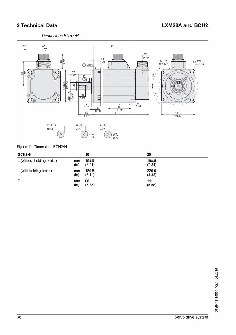
Dimensions BCH2∙H
371.46 32
1.26
451.77
50.20
120.47
Ø95
h7
Ø3.74
Ø22
h6
Ø0.87
18 0.71
mmin
6939
6.75
20
L
M6
46
100
73
7
Z45
8 h98 N9
45°
Ø9.2Ø0.36
1.77
1.81 Ø115
Ø4.534x
3.94
Ø22 h6Ø0.87
M4x6
0.28
0.27
0.79
200.79
1.542.72
2.87
45°
0.31 0.31
Figure 11: Dimensions BCH2∙H
BCH2∙H... 10 20L (without holding brake) mm
(in)153.5(6.04)
198.5(7.81)
L (with holding brake) mm(in)
180.5(7.11)
225.5(8.88)
Z mm(in)
96(3.78)
141(5.55)
2 Technical Data LXM28A and BCH2
36 Servo drive system
0198
4411
1405
4, V
2.1,
04.
2016

Dimensions BCH2∙M
R
mmin
T
46
73
W h9V N9
Ø9.2Ø0.361.
81
Ø145Ø5.71 4x
ØD h6
2.87 45
°
45°C
A60.24
11.50.45
Ø11
0h7
Ø4.33
ØD
h6
6837.5
N
L
M130
8
Z
5.12
M4x8
0.31
200.79
1.482.68
F
Figure 12: Dimensions BCH2∙M
BCH2∙M... 08 03, 05, 06, 10 09, 15 20L (without holding brake) mm
(in)187(7.36)
147(5.79)
163(6.42)
187(7.36)
L (with holding brake) mm(in)
216(8.5)
183(7.2)
198(7.8)
216(8.5)
A mm(in)
48(1.89)
55(2.17)
55(2.17)
55(2.17)
C mm(in)
40(1.57)
47(1.85)
47(1.85)
47(1.85)
D mm(in)
19(0.75)
22(0.87)
22(0.87)
22(0.87)
F mm(in)
25(0.98)
36(1.42)
36(1.42)
36(1.42)
M - M6 M8 M8 M8
N mm(in)
16(0.63)
19(0.75)
19(0.75)
19(0.75)
R mm(in)
15.5(0.61)
18(0.71)
18(0.71)
18(0.71)
T mm(in)
6(0.24)
7(0.28)
7(0.28)
7(0.28)
V mm(in)
6(0.24)
8(0.31)
8(0.31)
8(0.31)
W mm(in)
6(0.24)
8(0.31)
8(0.31)
8(0.31)
Z mm(in)
134.5(5.30)
94.5(3.72)
110.5(4.35)
134.5(5.30)
LXM28A and BCH2 2 Technical Data
Servo drive system 37
0198
4411
1405
4, V
2.1,
04.
2016

Dimensions BCH2∙R
40.16
Ø11
4.3
h7Ø4.5
ØD
h6
mmin
71.539
65
180
73
Z
Ø13.5Ø0.532.
56 Ø200Ø7.87 4x
7.09
200.79
1.542.81
2.87
A
C
L
F
N
M
200.79
45°
45°
451.77
R
W h9V N9ØD h680.31
M6x12
Figure 13: Dimensions BCH2∙R
BCH2∙R... 20 30 35 45L (without holding brake) mm
(in)169(6.65)
202(7.95)
202(7.95)
235(9.25)
L (with holding brake) mm(in)
203(7.99)
235(9.25)
235(9.25)
279(10.98)
A mm(in)
79(3.11)
79(3.11)
79(3.11)
79(3.11)
C mm(in)
73(2.87)
73(2.87)
73(2.87)
73(2.87)
D mm(in)
35(1.38)
35(1.38)
35(1.38)
35(1.38)
F mm(in)
63(2.48)
63(2.48)
63(2.48)
63(2.48)
M - M12 M12 M12 M12
N mm(in)
28(1.10)
28(1.10)
28(1.10)
28(1.10)
R mm(in)
30(1.18)
30(1.18)
30(1.18)
30(1.18)
V mm(in)
10(0.39)
10(0.39)
10(0.39)
10(0.39)
W mm(in)
10(0.39)
10(0.39)
10(0.39)
10(0.39)
Z mm(in)
103(4.06)
136(5.35)
136(5.35)
169(6.65)
2 Technical Data LXM28A and BCH2
38 Servo drive system
0198
4411
1405
4, V
2.1,
04.
2016

2.2.3 Tightening torque and property class of screws
Housing screws Tightening torqueM3 * 0.50 Nm (lb.in) 1 (8.85)
M4 * 0.70 Nm (lb.in) 2.9 (25.67)
M5 * 0.80 Nm (lb.in) 5.9 (52.22)
M6 * 1.00 Nm (lb.in) 9.9 (87.62)
M7 * 1.25 Nm (lb.in) 24 (212.40)
M8 * 1.50 Nm (lb.in) 49 (433.65)
Property class of the screws H 8.8
LXM28A and BCH2 2 Technical Data
Servo drive system 39
0198
4411
1405
4, V
2.1,
04.
2016

2.3 Electrical Data
2.3.1 Electrical data drive
The products are intended for industrial use and may only be operatedwith a permanently installed connection.
Mains voltage: range and toler-ance 220 Vac single-phase/three-phase Vac 200 -15 % ... 230 +10 %
Frequency Hz 50 -5 % ... 60 +5 %
Transient overvoltages Overvoltage category III 1)
Rated voltage to ground Vac 2301) Depends on installation altitude, see chapter "2.1 Ambient conditions"
Type of groundingTT system, TN system Approved
IT system Not approved
Mains with grounded line conduc-tor
Not approved
Leakage currentLeakage current (as perIEC 60990, figure 3)
mA <30 1)
1) Measured on mains with grounded neutral point and without external mains filter.Take into account that a 30 mA RCD can already trigger at 15 mA. In addition, thereis a high-frequency leakage current which is not considered in the measurement.The response to this depends on the type of residual current device.
Monitoring of the continuous out-put power
The continuous output power is monitored by the device. If the contin-uous output power is exceeded, the device reduces the output cur-rent.
PWM frequency power stage The PWM frequency of the power stage is set to a fixed value.
LXM28∙... UA5, U01, U02,U04, U07, U10,U15
U20, U30, U45
PWM frequency power stage kHz 16 8
Permissible product combinations The following motors can be connected to this device family: BCH2.See chapter "1.5 Permissible product combinations" for a list of per-missible product combinations.
Inquire for other motors.
2 Technical Data LXM28A and BCH2
40 Servo drive system
0198
4411
1405
4, V
2.1,
04.
2016

2.3.1.1 Data for devices connected via a single phase
LXM28∙... UA5 U01 U02 U04Nominal voltage V 230 (1 ∼) 230 (1 ∼) 230 (1 ∼) 230 (1 ∼)
Inrush current limitation A 8 8 8 8
Maximum fuse to be connected upstream1)
A 25 25 25 25
Short-circuit current rating (SCCR) kA 5 5 5 5
Continuous output current Arms 0.64 0.9 1.5 2.6
Peak output current Arms 2 2.7 4.5 7.8
Nominal power 2) W 50 100 200 400
Input current 2) 3) Arms 0.8 1.2 2.4 3.8
THD (total harmonic distortion) 2) 4) % 262.8 239.2 226.8 211.6
Power dissipation 5) W 8 10 14 22
Maximum inrush current 6) A 175 175 175 175
Time for maximum inrush current ms 0.5 0.5 0.5 0.51) As per IEC 60269; Circuit breakers with C characteristic; See "2.6 Conditions for UL 508C" for UL and CSA; Lower ratings are per-
missible; The fuse must be rated in such a way that the fuse does not trip at the specified input current.2) At a mains impedance corresponding to the short-circuit current rating (SCCR).3) At nominal power and nominal voltage4) with reference to the input current5) Condition: internal braking resistor not active; value at nominal current, nominal voltage and nominal power; value approximately
proportional with output current6) Extreme case, off/on pulse before the inrush current limitation responds, see next line for maximum time
LXM28∙... U07 U10 U15Nominal voltage V 230 (1 ∼) 230 (1 ∼) 230 (1 ∼)
Inrush current limitation A 8 8 8
Maximum fuse to be connected upstream1)
A 25 25 25
Short-circuit current rating (SCCR) kA 5 5 5
Continuous output current Arms 4.5 7 7
Peak output current Arms 13.5 21 21
Nominal power 2) W 750 1000 1500
Input current 2) 3) Arms 6 8.5 10
THD (total harmonic distortion) 2) 4) % 181.8 176.3 166.6
Power dissipation 5) W 38 36 41
Maximum inrush current 6) A 175 235 235
Time for maximum inrush current ms 0.5 0.6 0.61) As per IEC 60269; Circuit breakers with C characteristic; See "2.6 Conditions for UL 508C" for UL and CSA; Lower ratings are per-
missible; The fuse must be rated in such a way that the fuse does not trip at the specified input current.2) At a mains impedance corresponding to a short-circuit current of the supply mains of 1 kA3) At nominal power and nominal voltage4) with reference to the input current5) Condition: internal braking resistor not active; value at nominal current, nominal voltage and nominal power; value approximately
proportional with output current6) Extreme case, off/on pulse before the inrush current limitation responds, see next line for maximum time
LXM28A and BCH2 2 Technical Data
Servo drive system 41
0198
4411
1405
4, V
2.1,
04.
2016

2.3.1.2 Data for devices connected via three phases
LXM28∙... UA5 U01 U02 U04 U07Nominal voltage V 230 (3 ∼) 230 (3 ∼) 230 (3 ∼) 230 (3 ∼) 230 (3 ∼)
Inrush current limitation A 8 8 8 8 8
Maximum fuse to be connected upstream1)
A 25 25 25 25 25
Short-circuit current rating (SCCR) kA 5 5 5 5 5
Continuous output current Arms 0.64 0.9 1.5 2.6 4.5
Peak output current Arms 2 2.7 4.5 7.8 13.5
Nominal power 2) W 50 100 200 400 750
Input current 2) 3) Arms 0.42 0.74 1.25 2.2 3.9
THD (total harmonic distortion) 2) 4) % 227 212.7 200.7 183.7 160.8
Power dissipation 5) W 8 10 14 22 38
Maximum inrush current 6) A 175 175 175 175 175
Time for maximum inrush current ms 0.5 0.5 0.5 0.5 0.51) As per IEC 60269; Circuit breakers with C characteristic; See "2.6 Conditions for UL 508C" for UL and CSA; Lower ratings are per-
missible; The fuse must be rated in such a way that the fuse does not trip at the specified input current.2) At a mains impedance corresponding to a short-circuit current of the supply mains of 1 kA3) At nominal power and nominal voltage4) with reference to the input current5) Condition: internal braking resistor not active; value at nominal current, nominal voltage and nominal power; value approximately
proportional with output current6) Extreme case, off/on pulse before the inrush current limitation responds, see next line for maximum time
LXM28∙... U10 U15 U20 U30 U45Nominal voltage V 230 (3 ∼) 230 (3 ∼) 230 (3 ∼) 230 (3 ∼) 230 (3 ∼)
Inrush current limitation A 8 8 19.2 17 17
Maximum fuse to be connected upstream1)
A 25 25 32 32 32
Short-circuit current rating (SCCR) kA 5 5 5 22 22
Continuous output current Arms 7 7 12 19.8 22.87
Peak output current Arms 21 21 36 60 61
Nominal power 2) W 1000 1500 2000 3000 4500
Input current 2) 3) Arms 5 5.9 8.7 12.9 18
THD (total harmonic distortion) 2) 4) % 155.5 144.8 137.1 155.8 147.1
Power dissipation 5) W 36 41 41 97 97
Maximum inrush current 6) A 235 235 295 300 300
Time for maximum inrush current ms 0.6 0.6 1.0 1.0 1.01) As per IEC 60269; Circuit breakers with C characteristic; See "2.6 Conditions for UL 508C" for UL and CSA; Lower ratings are per-
missible; The fuse must be rated in such a way that the fuse does not trip at the specified input current.2) At a mains impedance corresponding to a short-circuit current of the supply mains of 1 kA3) At nominal power and nominal voltage4) with reference to the input current5) Condition: internal braking resistor not active; value at nominal current, nominal voltage and nominal power; value approximately
proportional with output current6) Extreme case, off/on pulse before the inrush current limitation responds, see next line for maximum time
2 Technical Data LXM28A and BCH2
42 Servo drive system
0198
4411
1405
4, V
2.1,
04.
2016

2.3.1.3 DC bus data for drives connected via a single phase
LXM28∙... UA5 U01 U02 U04 U07 U10 U15Nominal voltage (single-phase) Vac 230 230 230 230 230 230 230
Nominal voltage DC bus Vdc 322 322 322 322 322 322 322
Undervoltage limit Vdc 160 160 160 160 160 160 160
Overvoltage limit Vdc 420 420 420 420 420 420 420
Maximum continuous power via DC bus W 50 100 200 400 750 1000 1500
Maximum continuous current via DC bus A 0.2 0.3 0.6 1.2 2.3 3.1 4.6
2.3.1.4 DC bus data for drives connected via three phases
LXM28∙... UA5 U01 U02 U04 U07Nominal voltage (three-phase) Vac 230 230 230 230 230
Nominal voltage DC bus Vdc 322 322 322 322 322
Undervoltage limit Vdc 160 160 160 160 160
Overvoltage limit Vdc 420 420 420 420 420
Maximum continuous power via DC bus W 50 100 200 400 750
Maximum continuous current via DC bus A 0.2 0.3 0.6 1.2 2.3
LXM28∙... U10 U15 U20 U30 U45Nominal voltage (three-phase) Vac 230 230 230 230 230
Nominal voltage DC bus Vdc 322 322 322 322 322
Undervoltage limit Vdc 160 160 160 160 160
Overvoltage limit Vdc 420 420 420 420 420
Maximum continuous power via DC bus W 1000 1500 2000 3000 4500
Maximum continuous current via DC bus A 3.1 4.6 6.2 9.2 13.8
LXM28A and BCH2 2 Technical Data
Servo drive system 43
0198
4411
1405
4, V
2.1,
04.
2016

2.3.1.5 SignalsThe outputs are short-circuit protected. The inputs and outputs aregalvanically isolated.
The digital inputs and outputs of this product can be wired for logictype 1 or logic type 2.
Logic type Active state(1) Logic type 1 Output supplies current (source output)
Current flows to the input
(2) Logic type 2 Output draws current (sink output)Current flows from the input
Analog output signalsVoltage range V -8 ... 8
Output current mA 10
Minimum load resistance (voltagesource)
kΩ 1
Resolution Bit 12
Sampling period ms 1
Time constant μs 10
Digital input signals 24 V When wired as logic type 1, the levels of the opto-isolated inputsDI1 ... DI5 and DI8 comply with IEC 61131-2, type 1.
Level 0 with logic type 1 (Ulow) Vdc ≤5
Level 1 with logic type 1 (Uhigh) Vdc ≥11
Input current (typical) mA 6
Debounce time 1) ms 0 ... 201) Adjustable via parameter P2-09 in increments of 1 ms.
Touch probe input signals 24 V When wired as "logic type 1", the levels of the opto-isolated inputsDI6 and DI7 comply with IEC 61131-2, type 1.
Level 0 with logic type 1 (Ulow) Vdc ≤5
Level 1 with logic type 1 (Uhigh) Vdc ≥11
Input current (typical) mA 7
Debounce time 1) μs 0 ... 100
Jitter Capture μs 11) Adjustable via parameter P2-24 in increments of 1 μs.
Safety function STO The signal inputs STO_0V and STO_24V (CN9) are protected againstreverse polarity.
2 Technical Data LXM28A and BCH2
44 Servo drive system
0198
4411
1405
4, V
2.1,
04.
2016

Nominal voltage Vdc 24
PELV power supply unit Required
Level 0 with logic type 1 (Ulow) 1) Vdc < 5
Level 1 with logic type 1 (Uhigh) 1) Vdc 15 ... 30
Input current (typical)LXM28∙UA5, U01, U02, U04, U07LXM28∙U10, U15LXM28∙U20LXM28∙U30, U45
mA110120130160
Maximum frequency for OSSD(Output Signal Switching Device)test pulses
Hz 475
Debounce time ms < 1
Response time of safety functionSTO
ms < 40
1) voltage level according to IEC 61131-2 type 2 with the exception of the operationwith 15 Vdc instead of 11 Vdc. The condition between 5 Vdc and 15 Vdc is unde-fined and not permissible.
The 24 V supply 24V_OUT and 0V_OUT (CN9) for deactivating thesafety function STO are short-circuit protected.
Digital output signals 24 V The levels of the digital 24 V output signals DO∙ comply withIEC 61131-2.
Switching voltage Vdc 24
Maximum switching current mA 100
Voltage drop at 100 mA load Vdc < 3
24 Vdc power supply (pin 17)Output voltage Vdc 24
Maximum output current mA 200
CAN bus signals The CAN bus signals comply with the CAN standard and are short-cir-cuit protected.
ESIM output signals The ESIM output signals comply with the RS422 interface specifica-tion.
Logic level As per RS422 1)
Output frequency per signal kHz 800
Maximum output frequency (quad-ruple evaluation)
kHz 3200
1) Due to the input current of the optocoupler in the input circuit, a parallel connectionof a driver output to several devices is not permitted.
LXM28A and BCH2 2 Technical Data
Servo drive system 45
0198
4411
1405
4, V
2.1,
04.
2016

Function A/B signals External A/B signals can be supplied via the PTI input as referencevalues in operating mode Pulse Train (Pt).
Signal FunctionSignal SIGN before signal PULSE Movement in positive direction
Signal PULSE before signal SIGN Movement in negative direction
PULSE0
1
0
1SIGN
P1-01 C = 0
P1-00 C = 0
+ -
..7 ... ...8 9 1312 13 9 8..14 1415
3
1
2 2
3
Figure 14: Time chart with A/B signal, counting forwards and backwards
The signal shape shown relates to the factory setting (P1-00 C=0).
The direction of movement shown relates to the factory setting (P1-01C=0).
Times (minimum) HPULSE / HSIGN with RS422 PULSE / SIGN with RS422 PULSE / SIGN with OpenCollector
(1) 4 MHz 500 kHz 200 kHz
(2) 0.125 μs 0.1 μs 2.5 μs
(3) 0.0625 μs 0.5 μs 1.25 μs
2 Technical Data LXM28A and BCH2
46 Servo drive system
0198
4411
1405
4, V
2.1,
04.
2016

Function CW/CCW External CW/CCW signals can be supplied via the PTI input as refer-ence values.
Signal FunctionPULSE (CCW) Movement in positive direction
SIGN (CW) Movement in negative direction
20
1
0
1
PULSE(CCW)
SIGN(CW)
2
1
2 23
P1-01 C = 0
+ + - -
P1-00 C = 0
Figure 15: Time chart with "CW/CCW"
The signal shape shown relates to the factory setting (P1-00 C=0).
The direction of movement shown relates to the factory setting (P1-01C=0).
Times (minimum) HPULSE / HSIGN with RS422 PULSE / SIGN with RS422 PULSE / SIGN with OpenCollector
(1) 4 MHz 500 kHz 200 kHz
(2) 0.125 μs 0.1 μs 2.5 μs
(3) 0.0625 μs 0.5 μs 1.25 μs
LXM28A and BCH2 2 Technical Data
Servo drive system 47
0198
4411
1405
4, V
2.1,
04.
2016

Function P/D External P/D signals can be supplied via the PTI input as referencevalues.
Signal FunctionPULSE Motor movementSIGN Direction of movement
0
1
0
1
PULSE
SIGN
322
2
4
1
P1-01 C = 0
P1-00 C = 0
+ ++ -
Figure 16: Time chart with pulse/direction signal
The signal shape shown relates to the factory setting (P1-00 C=0).
The direction of movement shown relates to the factory setting (P1-01C=0).
Times (minimum) HPULSE / HSIGN with RS422 PULSE / SIGN with RS422 PULSE / SIGN with OpenCollector
(1) 4 MHz 500 kHz 200 kHz
(2) 0.125 μs 0.1 μs 2.5 μs
(3) 0.0625 μs 0.5 μs 1.25 μs
(4) 0.0625 μs 0.5 μs 1.25 μs
2 Technical Data LXM28A and BCH2
48 Servo drive system
0198
4411
1405
4, V
2.1,
04.
2016

2.3.1.6 Functional safetyData for maintenance plan and thecalculations for the safety function
The safety function must be tested at regular intervals. The intervaldepends on the hazard and risk analysis of the total system. The mini-mum interval is 1 year (high demand mode as per IEC 61508).
Use the following data of the safety function STO for your mainte-nance plan and the calculations for the safety function:
Lifetime of the safety functionSTO (IEC 61508) 1)
Years 20
SFF (IEC 61508)Safe Failure Fraction
% 98.9
Safety integrity levelIEC 61508IEC 62061IEC 61800-5-2
SIL CL 2
PFH (IEC 61508)Probability of Dangerous Hard-ware Failure per Hour
1/h STO_A 2): 1.7*10-9 STO_B 3): 1.5*10-9
PFDavg (IEC 61508)Probability of Failure on Demand,calculated as one demand peryear
STO_A 2): 1.5*10-4 STO_B 3): 1.3*10-4
PL (ISO 13849-1)Performance Level
d (category 3)
MTTFd (ISO 13849-1)Mean Time to Dangerous Failure
Years STO_A 2): 66757STO_B 3): 78457
DCavg (ISO 13849-1)Diagnostic Coverage
% ≥90
1) See chapter "13.2.1.1 Lifetime safety function STO".2) STO_A: LXM28AUA5, LXM28AU01, LXM28AU02, LXM28AU04, LXM28AU07,
LXM28AU10, LXM28AU15, LXM28AU203) STO_B: LXM28AU30, LXM28AU45
If two non-adjacent IGBTs have a short circuit, a movement of a maxi-mum of 120 degrees (electrical) can occur even if the safety functionSTO is active. Include in your risk analysis the probability of IGBTshort circuits, and make a determination whether it is acceptable as itrelates to your application.
WARNINGUNINTENTIONAL MOVEMENT DURING STO FUNCTION
Use appropriate safety interlocks (such as a service brake) wherepersonnel and/or equipment hazards exist.
Failure to follow these instructions can result in death, seriousinjury, or equipment damage.
The probability of such a condition is 1.5 * 10-15 per hour (without com-mon cause failure). Include this in your calculations for the safetyfunction.
Contact your local sales office for additional data, if required.
2.3.1.7 Braking resistorThe device has an internal braking resistor. If the internal brakingresistor is insufficient for the dynamics of the application, one or moreexternal braking resistors must be used.
LXM28A and BCH2 2 Technical Data
Servo drive system 49
0198
4411
1405
4, V
2.1,
04.
2016

The resistance values for external braking resistors must not be belowthe specified minimum resistance. If an external braking resistor isactivated by means of the appropriate parameter, the internal brakingresistor is deactivated.
LXM28∙... UA5 U01 U02 U04 U07Resistance value of internal brakingresistor
Ω 100 100 100 100 40
Continuous power internal braking resis-tor PPR
W 60 60 60 60 60
Peak energy ECR 1) Ws 152 152 152 152 380
External braking resistor minimum Ω 25 25 25 25 25
External braking resistor maximum 2) Ω 50 50 50 50 50
Maximum continuous power externalbraking resistor
W 640 640 640 640 640
Switch-on voltage braking resistor V 390 390 390 390 390
Capacitance of the internal capacitors μF 820 820 820 820 820
Energy absorption of internal capacitorsEvar at nominal voltage 230 V +10%
Ws 8.87 8.87 8.87 8.87 8.87
1) Parameter P1-71 is set to 100 ms.2) The maximum specified braking resistor can derate the peak power of the device. Depending on the application, it is possible to use
a higher ohm resistor.
LXM28∙... U10 U15 U20 U30 U45Resistance value of internal brakingresistor
Ω 40 40 40 22 22
Continuous power internal braking resis-tor PPR
W 60 60 60 100 100
Peak energy ECR 1) Ws 380 380 380 691 691
External braking resistor minimum Ω 15 15 8 8 8
External braking resistor maximum 2) Ω 50 50 25 25 25
Maximum continuous power externalbraking resistor
W 1000 1000 1500 2500 2500
Switch-on voltage braking resistor V 390 390 390 390 390
Capacitance of the internal capacitors μF 1640 1640 2110 3280 3280
Energy absorption of internal capacitorsEvar at nominal voltage 230 V +10%
Ws 17.76 17.76 22.82 35.51 35.51
1) Parameter P1-71 is set to 100 ms.2) The maximum specified braking resistor can derate the peak power of the device. Depending on the application, it is possible to use
a higher ohm resistor.
2 Technical Data LXM28A and BCH2
50 Servo drive system
0198
4411
1405
4, V
2.1,
04.
2016

2.3.2 Electrical data motor
2.3.2.1 BCH2∙B
BCH2... 1) MBA53 MB013Technical data - generalContinuous stall torque 2) M0 Nm 0.16 0.32
Peak torque Mmax Nm 0.32 0.96
With supply voltage Un = 230 Vac )
Nominal speed of rotation nN rpm 3000 3000
Nominal torque MN Nm 0.16 0.32
Nominal Current IN Arms 0.59 0.89
Nominal power PN kW 0.05 0.10
Technical data - electricalMaximum winding voltage Umax Vac 255 255
Maximum winding voltage Umax Vdc 360 360
Maximum voltage to ground Vac 255 255
Maximum Current Imax Arms 1.8 2.7
Continuous stall current I0 Arms 0.54 0.81
Voltage constant 3) kEu-v Vrms 18 24
Torque constant 4) kt Nm/A 0.30 0.40
Winding resistance R20u-v Ω 31.0 23.4
Winding inductance Lqu-v mH 26.4 21.5
Winding inductance Ldu-v mH 24.7 20.6
Technical data - mechanicalMaximum permissible speedof rotation
nmax rpm 5000 5000
Rotor inertia without brake JM kgcm2 0.054 0.075
Rotor inertia with brake JM kgcm2 0.055 0.076
Mass without brake m kg 0.40 0.56
Mass with brake m kg 0.60 0.77
Technical data - holding brakeHolding torque Nm 0.32 0.32
Nominal voltage Vdc 24 +/-10% 24 +/-10%
Nominal power (electrical pull-in power)
W 4.4 4.4
1) Limit values with flanged motor, see table on page 28.2) M0=Continuous stall torque at low speed of rotation and 100% duty cycle; at speeds of rotation of < 20 rpm the continuous stall
torque is reduced to 87%3) RMS value at 1000 rpm and 20°C (68°F)4) At n = 20 rpm and 20°C (68°F)
LXM28A and BCH2 2 Technical Data
Servo drive system 51
0198
4411
1405
4, V
2.1,
04.
2016

2.3.2.2 BCH2∙D
BCH2... 1) LD023 LD043Technical data - generalContinuous stall torque 2) M0 Nm 0.64 1.27
Peak torque Mmax Nm 1.92 3.81
With supply voltage Un = 230 Vac
Nominal speed of rotation nN rpm 3000 3000
Nominal torque MN Nm 0.64 1.27
Nominal Current IN Arms 1.30 2.50
Nominal power PN kW 0.20 0.40
Technical data - electricalMaximum winding voltage Umax Vac 255 255
Maximum winding voltage Umax Vdc 360 360
Maximum voltage to ground Vac 255 255
Maximum Current Imax Arms 4.5 7.8
Continuous stall current I0 Arms 1.11 2.19
Voltage constant 3) kEu-v Vrms 35 35
Torque constant 4) kt Nm/A 0.58 0.58
Winding resistance R20u-v Ω 12.2 5.2
Winding inductance Lqu-v mH 24.8 12.5
Winding inductance Ldu-v mH 22.7 12.0
Technical data - mechanicalMaximum permissible speedof rotation
nmax rpm 5000 5000
Rotor inertia without brake JM kgcm2 0.16 0.27
Rotor inertia with brake JM kgcm2 0.17 0.28
Mass without brake m kg 1.02 1.45
Mass with brake m kg 1.50 2.00
Technical data - holding brakeHolding torque Nm 1.3 1.3
Nominal voltage Vdc 24 +/-10% 24 +/-10%
Nominal power (electrical pull-in power)
W 11.2 11.2
1) Limit values with flanged motor, see table on page 28.2) M0=Continuous stall torque at low speed of rotation and 100% duty cycle; at speeds of rotation of < 20 rpm the continuous stall
torque is reduced to 87%3) RMS value at 1000 rpm and 20°C (68°F)4) At n = 20 rpm and 20°C (68°F)
2 Technical Data LXM28A and BCH2
52 Servo drive system
0198
4411
1405
4, V
2.1,
04.
2016

2.3.2.3 BCH2∙F
BCH2... 1) LF043 HF073 LF073Technical data - generalContinuous stall torque 2) M0 Nm 1.27 2.39 2.39
Peak torque Mmax Nm 3.81 7.16 7.16
With supply voltage Un = 230 Vac
Nominal speed of rotation nN rpm 3000 3000 3000
Nominal torque MN Nm 1.27 2.39 2.39
Nominal Current IN Arms 2.52 4.29 4.29
Nominal power PN kW 0.40 0.75 0.75
Technical data - electricalMaximum winding voltage Umax Vac 255 255 255
Maximum winding voltage Umax Vdc 360 360 360
Maximum voltage to ground Vac 255 255 255
Maximum Current Imax Arms 7.8 13.5 13.5
Continuous stall current I0 Arms 2.29 4.01 4.01
Voltage constant 3) kEu-v Vrms 33.5 36 36
Torque constant 4) kt Nm/A 0.55 0.60 0.60
Winding resistance R20u-v Ω 3.20 1.50 1.50
Winding inductance Lqu-v mH 12.0 6.6 6.6
Winding inductance Ldu-v mH 11.3 6.1 6.1
Technical data - mechanicalMaximum permissible speed ofrotation
nmax rpm 5000 5000 5000
Rotor inertia without brake JM kgcm2 0.67 1.54 1.19
Rotor inertia with brake JM kgcm2 0.72 1.59 1.24
Mass without brake m kg 2.00 2.90 2.80
Mass with brake m kg 2.80 3.70 3.60
Technical data - holding brakeHolding torque Nm 2.5 2.5 2.5
Nominal voltage Vdc 24 +/-10% 24 +/-10% 24 +/-10%
Nominal power (electrical pull-inpower)
W 10.2 10.2 10.2
1) Limit values with flanged motor, see table on page 28.2) M0=Continuous stall torque at low speed of rotation and 100% duty cycle; at speeds of rotation of < 20 rpm the continuous stall
torque is reduced to 87%3) RMS value at 1000 rpm and 20°C (68°F)4) At n = 20 rpm and 20°C (68°F)
LXM28A and BCH2 2 Technical Data
Servo drive system 53
0198
4411
1405
4, V
2.1,
04.
2016

2.3.2.4 BCH2∙H
BCH2... 1) LH103 LH203Technical data - generalContinuous stall torque 2) M0 Nm 3.18 6.37
Peak torque Mmax Nm 9.54 19.11
With supply voltage Un = 230 Vac
Nominal speed of rotation nN rpm 3000 3000
Nominal torque MN Nm 3.18 6.37
Nominal Current IN Arms 6.64 10.27
Nominal power PN kW 1.00 2.00
Technical data - electricalMaximum winding voltage Umax Vac 255 255
Maximum winding voltage Umax Vdc 360 360
Maximum voltage to ground Vac 255 255
Maximum Current Imax Arms 20.0 35.0
Continuous stall current I0 Arms 5.83 9.87
Voltage constant 3) kEu-v Vrms 33 39
Torque constant 4) kt Nm/A 0.55 0.65
Winding resistance R20u-v Ω 0.67 0.36
Winding inductance Lqu-v mH 4.3 2.6
Winding inductance Ldu-v mH 4.20 2.59
Technical data - mechanicalMaximum permissible speedof rotation
nmax rpm 5000 5000
Rotor inertia without brake JM kgcm2 2.40 4.28
Rotor inertia with brake JM kgcm2 2.45 4.35
Mass without brake m kg 4.60 6.70
Mass with brake m kg 5.10 7.20
Technical data - holding brakeHolding torque Nm 6.5 6.5
Nominal voltage Vdc 24 +/-10% 24 +/-10%
Nominal power (electrical pull-in power)
W 10.4 10.4
1) Limit values with flanged motor, see table on page 28.2) M0=Continuous stall torque at low speed of rotation and 100% duty cycle; at speeds of rotation of < 20 rpm the continuous stall
torque is reduced to 87%3) RMS value at 1000 rpm and 20°C (68°F)4) At n = 20 rpm and 20°C (68°F)
2 Technical Data LXM28A and BCH2
54 Servo drive system
0198
4411
1405
4, V
2.1,
04.
2016

2.3.2.5 BCH2∙M
BCH2... 1) MM052 MM031 MM102 HM102 MM081Technical data - generalContinuous stall torque 2) M0 Nm 2.39 2.86 4.77 4.77 5.39
Peak torque Mmax Nm 7.16 8.59 14.30 14.30 13.80
With supply voltage Un = 230 Vac
Nominal speed of rotation nN rpm 2000 1000 2000 2000 1500
Nominal torque MN Nm 2.39 2.86 4.77 4.77 5.39
Nominal Current IN Arms 3.24 2.09 6.29 6.29 6.29
Nominal power PN kW 0.50 0.30 1.00 1.00 0.85
Technical data - electricalMaximum winding voltage Umax Vac 255 255 255 255 255
Maximum winding voltage Umax Vdc 360 360 360 360 360
Maximum voltage to ground Vac 255 255 255 255 255
Maximum Current Imax Arms 9.5 6.0 20.0 20.0 15.0
Continuous stall current I0 Arms 2.89 1.88 5.77 5.77 5.62
Voltage constant 3) kEu-v Vrms 50 92 50 50 58
Torque constant 4) kt Nm/A 0.83 1.52 0.83 0.83 0.96
Winding resistance R20u-v Ω 0.74 2.08 0.74 0.74 0.42
Winding inductance Lqu-v mH 7.84 26.25 7.84 7.84 4.70
Winding inductance Ldu-v mH 7.14 23.91 7.14 7.14 4.30
Technical data - mechanicalMaximum permissible speedof rotation
nmax rpm 3000 2000 3000 3000 3000
Rotor inertia without brake JM kgcm2 6.63 6.63 6.63 8.41 13.5
Rotor inertia with brake JM kgcm2 6.91 6.91 6.91 8.54 14.1
Mass without brake m kg 7.00 7.00 7.00 7.10 9.60
Mass with brake m kg 8.20 8.20 8.20 8.30 10.90
Technical data - holding brakeHolding torque Nm 9.6 9.6 9.6 9.6 9.6
Nominal voltage Vdc 24 +/-10% 24 +/-10% 24 +/-10% 24 +/-10% 24 +/-10%
Nominal power (electricalpull-in power)
W 19.7 19.7 19.7 19.7 19.7
1) Limit values with flanged motor, see table on page 28.2) M0=Continuous stall torque at low speed of rotation and 100% duty cycle; at speeds of rotation of < 20 rpm the continuous stall
torque is reduced to 87%3) RMS value at 1000 rpm and 20°C (68°F)4) At n = 20 rpm and 20°C (68°F)
LXM28A and BCH2 2 Technical Data
Servo drive system 55
0198
4411
1405
4, V
2.1,
04.
2016

BCH2... 1) MM061 MM091 MM152 MM202Technical data - generalContinuous stall torque 2) M0 Nm 5.73 8.59 7.16 9.55
Peak torque Mmax Nm 17.19 25.77 21.48 28.65
With supply voltage Un = 230 Vac
Nominal speed of rotation nN rpm 1000 1000 2000 2000
Nominal torque MN Nm 5.73 8.59 7.16 9.55
Nominal Current IN Arms 4.10 6.15 6.74 11.25
Nominal power PN kW 0.60 0.90 1.50 2.00
Technical data - electricalMaximum winding voltage Umax Vac 255 255 255 255
Maximum winding voltage Umax Vdc 360 360 360 360
Maximum voltage to ground Vac 255 255 255 255
Maximum Current Imax Arms 13.5 20.0 21.0 33.0
Continuous stall current I0 Arms 3.77 5.64 6.18 9.95
Voltage constant 3) kEu-v Vrms 92 92 70 58
Torque constant 4) kt Nm/A 1.52 1.52 1.16 0.96
Winding resistance R20u-v Ω 2.08 1.22 0.64 0.42
Winding inductance Lqu-v mH 26.25 16.40 7.20 4.70
Winding inductance Ldu-v mH 23.91 14.90 6.40 4.30
Technical data - mechanicalMaximum permissible speedof rotation
nmax rpm 2000 2000 3000 3000
Rotor inertia without brake JM kgcm2 6.63 9.70 9.70 13.50
Rotor inertia with brake JM kgcm2 6.91 10.00 10.00 14.10
Mass without brake m kg 7.00 7.60 7.60 9.70
Mass with brake m kg 8.20 8.80 8.80 11.00
Technical data - holding brakeHolding torque Nm 9.6 9.6 9.6 9.6
Nominal voltage Vdc 24 +/-10% 24 +/-10% 24 +/-10% 24 +/-10%
Nominal power (electricalpull-in power)
W 19.7 19.7 19.7 19.7
1) Limit values with flanged motor, see table on page 28.2) M0=Continuous stall torque at low speed of rotation and 100% duty cycle; at speeds of rotation of < 20 rpm the continuous stall
torque is reduced to 87%3) RMS value at 1000 rpm and 20°C (68°F)4) At n = 20 rpm and 20°C (68°F)
2 Technical Data LXM28A and BCH2
56 Servo drive system
0198
4411
1405
4, V
2.1,
04.
2016

2.3.2.6 BCH2∙R
BCH2... 1) MR202 HR202 MR302 MR301 MR352 MR451Technical data - generalContinuous stall torque 2) M0 Nm 9.55 9.55 14.32 19.10 16.70 28.65
Peak torque Mmax Nm 28.65 28.65 42.97 57.29 50.30 71.62
With supply voltage Un = 230 Vac )
Nominal speed of rotation nN rpm 2000 2000 2000 1500 2000 1500
Nominal torque MN Nm 9.55 9.55 14.32 19.10 16.70 28.65
Nominal Current IN Arms 9.6 9.6 18.8 18.8 19.3 22.8
Nominal power PN kW 2.00 2.00 3.00 3.00 3.50 4.50
Technical data - electricalMaximum winding voltage Umax Vac 255 255 255 255 255 255
Maximum winding voltage Umax Vdc 360 360 360 360 360 360
Maximum voltage to ground Vac 255 255 255 255 255 255
Maximum Current Imax Arms 35.5 35.5 56.0 61.0 61.0 61.0
Continuous stall current I0 Arms 8.75 8.75 16.33 16.49 16.83 19.68
Voltage constant 3) kEu-v Vrms 66 66 53 70 60 88
Torque constant 4) kt Nm/A 1.09 1.09 0.88 1.16 0.99 1.46
Winding resistance R20u-v Ω 0.572 0.572 0.168 0.234 0.168 0.199
Winding inductance Lqu-v mH 6.70 6.70 2.88 3.78 2.80 4.00
Winding inductance Ldu-v mH 6.10 6.10 2.71 3.45 2.57 3.80
Technical data - mechanicalMaximum permissible speed of rota-tion
nmax rpm 3000 3000 3000 3000 3000 3000
Rotor inertia without brake JM kgcm2 26.50 34.68 53.56 53.56 53.56 73.32
Rotor inertia with brake JM kgcm2 27.0 35.13 54.1 54.1 54.1 73.0
Mass without brake m kg 13.00 14.30 18.50 18.50 18.50 23.64
Mass with brake m kg 18.00 19.30 23.00 23.00 23.00 28.00
Technical data - holding brakeHolding torque Nm 48 48 48 48 48 48
Nominal voltage Vdc 24+/-10%
24+/-10%
24+/-10%
24+/-10%
24+/-10%
24+/-10%
Nominal power (electrical pull-inpower)
W 49.6 49.6 49.6 49.6 49.6 49.6
1) Limit values with flanged motor, see table on page 28.2) M0=Continuous stall torque at low speed of rotation and 100% duty cycle; at speeds of rotation of < 20 rpm the continuous stall
torque is reduced to 87%3) RMS value at 1000 rpm and 20°C (68°F)4) At n = 20 rpm and 20°C (68°F)
LXM28A and BCH2 2 Technical Data
Servo drive system 57
0198
4411
1405
4, V
2.1,
04.
2016

2.3.3 Electrical data (accessories)
2.3.3.1 External braking resistors
VW3A760... 1Rxx 1) 2Rxx 3Rxx 4Rxx 1) 5Rxx 6Rxx 7Rxx 1)
Resistance Ω 10 27 27 27 72 72 72
Continuous power W 400 100 200 400 100 200 400
Maximum time in braking at 115 V /230 V
s 0.72 0.552 1.08 2.64 1.44 3.72 9.6
Peak power at 115 V / 230 V kW 18.5 6.8 6.8 6.8 2.6 2.6 2.6
Maximum peak energy at 115 V / 230 V Ws 13300 3800 7400 18100 3700 9600 24700
Degree of protection IP65 IP65 IP65 IP65 IP65 IP65 IP65
UL approval (file no.) - E233422 E233422 - E233422 E233422 -1) Resistors with a continuous power of 400 W are not UL/CSA-approved.
VW3A77... 04 05Resistance Ω 15 10
Continuous power W 1000 1000
Maximum time in braking at 115 V /230 V
s 3.5 1.98
Peak power at 115 V / 230 V kW 12.3 18.5
Maximum peak energy at 115 V / 230 V Ws 43100 36500
Degree of protection IP20 IP20
UL approval (file no.) E226619 E226619
2 Technical Data LXM28A and BCH2
58 Servo drive system
0198
4411
1405
4, V
2.1,
04.
2016

2.3.3.2 External mains filtersSignal interference can cause unexpected responses of the drive andof other equipment in the vicinity of the drive.
WARNINGSIGNAL AND EQUIPMENT INTERFERENCE
• Only operate the drive with the specified external mains filter.• Install the wiring in accordance with the EMC requirements
described in the present document.• Verify compliance with the EMC requirements described in the
present document.• Verify compliance with all EMC regulations and requirements
applicable in the country in which the product is to be operatedand with all EMC regulations and requirements applicable at theinstallation site.
Failure to follow these instructions can result in death, seriousinjury, or equipment damage.
See chapter "4.1 Electromagnetic compatibility (EMC)" for additionalinformation on electromagnetic compatibility.
You can obtain EMC conformance by following the wiring standardsand practices in the present document and installing, for each drive,the following filter/drive combination:
LXM28A... Mains filter for single-phase connection
Mains filter for three-phase connection
UA5 = 0.05 kWU01 = 0.1 kWU02 = 0.2 kWU04 = 0.4 kWU07 = 0.75 kWU10 = 1 kW
VW3A4420 VW3A4422
U15 = 1.5 kW VW3A4421 VW3A4422
U20 = 2 kW - VW3A4423
U30 = 3 kWU45 = 4.5 kW
- VW3A4424
If you use mains filters of other manufacturers, these mains filtersmust have the same technical data as specified mains filters.
Emission The specified limit values are complied with if the external mains filtersavailable as accessories are used.
The following limit values for emission are complied with if the installa-tion is EMC-compliant and if the cables offered as accessories areused.
LXM28A... ∙∙∙Conducted interference Category C3
Radiated emission Category C3
Motor cables with a length exceeding 50 m (164 ft) are not permissi-ble.
LXM28A and BCH2 2 Technical Data
Servo drive system 59
0198
4411
1405
4, V
2.1,
04.
2016

Limit values This product meets the EMC requirements according to the standardIEC 61800-3 if the measures described in this manual are implemen-ted during installation.
However, if your entire system composition (products involved, mainsfilter, additional accessories and measures) does not meet therequirements of category C1, the following information applies as itappears in IEC 61800-3:
WARNINGRADIO INTERFERENCE
In a domestic environment this product may cause radio interferencein which case supplementary mitigation measures may be required.
Failure to follow these instructions can result in death, seriousinjury, or equipment damage.
As a system provider, you may have to include this information in thedocumentation to your customer.
2 Technical Data LXM28A and BCH2
60 Servo drive system
0198
4411
1405
4, V
2.1,
04.
2016

2.4 Characteristic curves
2.4.1 BCH2MB
BCH2MBA53 + LXM28∙UA5Without shaft sealing ring
0 1000 2000 3000 4000 5000
Mmax
M00.1
0.3
0.4
0.5
0
n [min-1]
M [Nm]
1
20.2
With shaft sealing ring
0 1000 2000 3000 4000 5000
Mmax
M00.1
0.3
0.4
0.5
0
n [min-1]
M [Nm]
1
20.2
BCH2MB013 + LXM28∙U01Without shaft sealing ring
0 1000 2000 3000 4000 5000
Mmax
M00.2
0.6
0.8
1.0
0
n [min-1]
M [Nm]
1
20.4
With shaft sealing ring
0 1000 2000 3000 4000 5000
Mmax
M00.2
0.6
0.8
1.0
0
n [min-1]
M [Nm]
1
20.4
(1) Peak torque(2) Continuous torque
2.4.2 BCH2LD
BCH2LD023 + LXM28∙U02 BCH2LD043 + LXM28∙U04
0 1000 2000 3000 4000 5000
Mmax
M00.5
1.0
2.0
1.5
0
n [min-1]
M [Nm]
1
2
0 1000 2000 3000 4000 5000
0.51.0
1.5
2.52.0
0
4.0
3.53.0
Mmax
M0
n [min-1]
M [Nm]
1
2
(1) Peak torque(2) Continuous torque
LXM28A and BCH2 2 Technical Data
Servo drive system 61
0198
4411
1405
4, V
2.1,
04.
2016

2.4.3 BCH2∙F
BCH2LF043 + LXM28∙U04
0 1000 2000 3000 4000 5000
0.51.0
1.5
2.52.0
0
4.0
3.53.0
Mmax
M0
n [min-1]
M [Nm]
1
2
BCH2HF073 + LXM28∙U07 BCH2LF073 + LXM28∙U07
0 1000 2000 3000 4000 5000
12
3
54
0
8
6
Mmax
M0
n [min-1]
M [Nm]
1
2
0 1000 2000 3000 4000 5000
12
3
54
0
8
6
Mmax
M0
n [min-1]
M [Nm]
1
2
(1) Peak torque(2) Continuous torque
2.4.4 BCH2LH
BCH2LH103 + LXM28∙U10 BCH2LH203 + LXM28∙U20
0 1000 2000 3000 4000 5000
2
4
6
10
8
0
Mmax
M0
n [min-1]
M [Nm]
1
2
0 1000 2000 3000 4000 5000
12
4
16
20
8
0
Mmax
M0
n [min-1]
M [Nm]
2
1
(1) Peak torque(2) Continuous torque
2 Technical Data LXM28A and BCH2
62 Servo drive system
0198
4411
1405
4, V
2.1,
04.
2016

2.4.5 BCH2∙M
BCH2MM052 + LXM28∙U07 BCH2MM031 + LXM28∙U04 BCH2MM102 + LXM28∙U10
1
3
5
2
4
6
8
0
Mmax
M0
n [min-1]
M [Nm]
1
0 1000 2000 30001500 2500500
2 2
4
6
10
8
0
Mmax
M0
n [min-1]
M [Nm]
0 1000 20001500500
1
21
5
7
9
0 1000 2000 30000
Mmax
M0
n [min-1]
M [Nm]
1500 2500500
2
1
5
15
10
2.5
12.5
7.5
BCH2HM102 + LXM28∙U10 BCH2MM081 + LXM28∙U10 BCH2MM061 + LXM28∙U07
0 1000 2000 30000
Mmax
M0
n [min-1]
M [Nm]
1500 2500500
2
1
5
15
10
2.5
12.5
7.5
0 1000 2000 30000
Mmax
M0
n [min-1]
M [Nm]
1500 2500500
1
52.5
15
10
12.5
7.5
24
8
12
20
16
0
Mmax
M0
n [min-1]
M [Nm]
0 1000 20001500500
1
22
10
14
18
BCH2MM091 + LXM28∙U10 BCH2MM152 + LXM28∙U15 BCH2MM202 + LXM28∙U20
0 1000 20000
Mmax
M0
n [min-1]
M [Nm]
1500500
25
25
15
20
30
10
1
0 1000 2000 30000
Mmax
M0
n [min-1]
M [Nm]
1500 2500500
25
25
15
20
10
1
0 1000 2000 30000
Mmax
M0
n [min-1]
M [Nm]
1500 2500500
2
1
5
25
15
20
30
10
(1) Peak torque(2) Continuous torque
LXM28A and BCH2 2 Technical Data
Servo drive system 63
0198
4411
1405
4, V
2.1,
04.
2016

2.4.6 BCH2∙R
BCH2MR202 + LXM28∙U20 BCH2HR202 + LXM28∙U20
0 1000 2000 30000
Mmax
M0
n [min-1]
M [Nm]
1500 2500500
2
1
5
25
15
20
30
10
0 1000 2000 30000
Mmax
M0
n [min-1]
M [Nm]
1500 2500500
2
1
5
25
15
20
30
10
BCH2MR302 + LXM28∙U30 BCH2MR301 + LXM28∙U30
0 1000 2000 3000
16
0
32
Mmax
M0
n [min-1]
M [Nm]
40
24
1500 2500500
8
48
2
1
0 1000 2000 30000
Mmax
M0
n [min-1]
M [Nm]
1500 2500500
2
150
20
60
10
30
40
BCH2MR352 + LXM28∙U45 BCH2MR451 + LXM28∙U45
0 1000 2000 30000
Mmax
M0
n [min-1]
M [Nm]
1500 2500500
2
150
20
60
10
30
40
0 1000 2000 30000
Mmax
M0
n [min-1]
M [Nm]
1500 2500500
2
1
50
20
80
10
3040
7060
(1) Peak torque(2) Continuous torque
2 Technical Data LXM28A and BCH2
64 Servo drive system
0198
4411
1405
4, V
2.1,
04.
2016

2.4.7 Overload characteristics curves
10
100
1000
10000
100000
1000000
100 150 200 250 300
% Inom of Drive
Ove
rload
tim
e in
ms
BCH2LFBCH2HFBCH2LH BCH2MMBCH2MR
BCH2LD043
BCH2LD023BCH2MB
Figure 17: Overload characteristics curves
LXM28A and BCH2 2 Technical Data
Servo drive system 65
0198
4411
1405
4, V
2.1,
04.
2016

2.5 Encoder
The drive can access the electronic nameplate via the electronic inter-face for easy commissioning.
The signals meet the PELV requirements.
Measuring range absolute 1 revolution
Resolution in increments Depending on evaluation
Accuracy of position ±0.044°
Supply voltage 4.1 ... 5.25 Vdc
Maximum supply current 100 mA
Maximum permissible speed ofrotation
6000 min-1
Maximum angular acceleration 100,000 rad/s2
2.6 Conditions for UL 508C
If the product is used to comply with UL 508C, the following conditionsmust also be met:
Wiring Use at least 75 °C (167 °F) copper conductors.
Fuses Use fuses as per UL 248 or circuit breaker as per UL 489.
LXM28∙ UA5, U01, U02,U04, U07, U10,U15
U20, U30, U45
Maximum fuse rating of fuse to beconnected upstream
A 25 32
Class if fuses are used J J
Class if circuit breakers are used D D
Overvoltage category "Use only in overvoltage category III or where the maximum availableRated Impulse Withstand Voltage Peak is equal or less than 4000Volts.", or equivalent as defined in UL 840 and its equivalent definedin IEC 60664-1.
2 Technical Data LXM28A and BCH2
66 Servo drive system
0198
4411
1405
4, V
2.1,
04.
2016
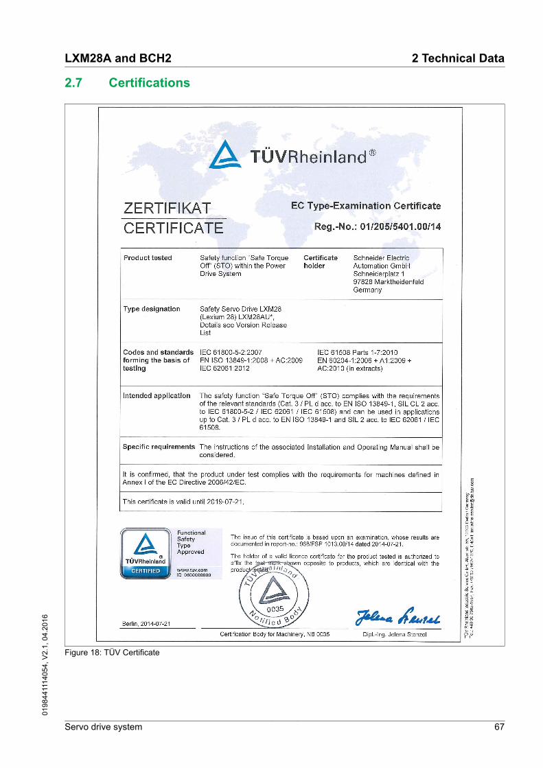
2.7 Certifications
Figure 18: TÜV Certificate
LXM28A and BCH2 2 Technical Data
Servo drive system 67
0198
4411
1405
4, V
2.1,
04.
2016

2.8 Declaration of conformity
2 Technical Data LXM28A and BCH2
68 Servo drive system
0198
4411
1405
4, V
2.1,
04.
2016

LXM28A and BCH2 2 Technical Data
Servo drive system 69
0198
4411
1405
4, V
2.1,
04.
2016

2 Technical Data LXM28A and BCH2
70 Servo drive system
0198
4411
1405
4, V
2.1,
04.
2016

LXM28A and BCH2 2 Technical Data
Servo drive system 71
0198
4411
1405
4, V
2.1,
04.
2016

2 Technical Data LXM28A and BCH2
72 Servo drive system
0198
4411
1405
4, V
2.1,
04.
2016

3 Basics
3.1 Functional safety
Automation and safety engineering are closely related. Engineering,installation and operation of complex automation solutions are greatlysimplified by integrated safety functions and safety modules.
Usually, the safety engineering requirements depend on the applica-tion. The level of the requirements results from, among other things,the risk and the hazard potential arising from the specific applicationand from the applicable standards and regulations.
Integrated safety function "SafeTorque Off" STO
The integrated safety function STO (IEC 61800-5-2) allows for a cate-gory 0 stop as per IEC 60204-1 without external power contactors. Itis not necessary to interrupt the supply voltage for a category 0 stop.This reduces the system costs and the response times.
In stop category 0, the drive coasts to a stop (provided there are noexternal forces operating to the contrary). The STO safety-relatedfunction is intended to help prevent an unintended start-up, not to stopa motor, and therefore corresponds to an unassisted stop in accord-ance with IEC 60204-1.
In circumstances where external influences are present, the coastdown time depends on physical properties of the components used(such as weight, torque, friction, etc.), and additional measures suchas mechanical service brakes may be necessary to help prevent anyhazard from materializing. That is to say, if this means a hazard toyour personnel or equipment, you must take appropriate measures(refer to Hazard and Risk Analysis).
WARNINGUNINTENDED EQUIPMENT OPERATION
• Make certain that no hazards can arise for persons or materialduring the coast down period of the axis/machine.
• Do not enter the zone of operation during the coast down period.• Ensure that no other persons can access the zone of operation
during the coast down period.• Use appropriate safety interlocks (such as a service brake) where
personnel and/or equipment hazards exist.
Failure to follow these instructions can result in death, seriousinjury, or equipment damage.
IEC 61508 and IEC 61800-5-2 The standard IEC 61508 "Functional safety of electrical/electronic/programmable electronic safety-related systems" defines the safety-related aspects of systems. Instead of a single functional unit of asafety-related system, the standard treats all elements of a functionchain as a unit. These elements must meet the requirements of thespecific safety integrity level as a whole.
The standard IEC 61800-5-2 "Adjustable speed electrical power drivesystems – Safety requirements – Functional" is a product standard
LXM28A and BCH2 3 Basics
Servo drive system 73
0198
4411
1405
4, V
2.1,
04.
2016

that defines the safety-related requirements regarding drives. Amongother things, this standard defines the safety functions for drives.
Safety Integrity Level (SIL) The standard IEC 61508 defines 4 safety integrity levels (Safety Integ-rity Level (SIL)). Safety integrity level SIL1 is the lowest level, safetyintegrity level SIL4 is the highest level. The safety integrity levelrequired for a given application is determined on the basis of the haz-ard potential resulting from the hazard and risk analysis. This is usedto decide whether the relevant function chain is to be considered as asafety-related function chain and which hazard potential it must cover.
Average Frequency of a Danger-ous Failure per Hour (PFH)
To maintain the function of the safety-related system, the IEC 61508standard requires various levels of measures for avoiding and control-ling faults, depending on the required safety integrity level (SafetyIntegrity Level (SIL)). All components must be subjected to a probabil-ity assessment to evaluate the effectiveness of the measures imple-mented for controlling faults. This assessment determines the proba-bility of a dangerous failure per hour PFH (Average Frequency of aDangerous Failure per Hour (PFH)) for a safety-related system. This isthe frequency per hour with which a safety-related system fails in ahazardous manner so that it can no longer perform its function cor-rectly. Depending on the SIL, the average frequency of a dangerousfailure per hour must not exceed certain values for the entire safety-related system. The individual PFH values of a function chain areadded. The result must not exceed the maximum value specified inthe standard.
SIL PFH at high demand or continuous demand4 ≥10-9 ... <10-8
3 ≥10-8 ... <10-7
2 ≥10-7 ... <10-6
1 ≥10-6 ... <10-5
3 Basics LXM28A and BCH2
74 Servo drive system
0198
4411
1405
4, V
2.1,
04.
2016

Hardware Fault Tolerance (HFT)and Safe Failure Fraction (SFF)
Depending on the safety integrity level (Safety Integrity Level (SIL)) forthe safety-related system, the IEC 61508 standard requires a specifichardware fault tolerance (Hardware Fault Tolerance (HFT)) in connec-tion with a specific safe failure fraction (Safe Failure Fraction (SFF)).The hardware fault tolerance is the ability of a safety-related system toexecute the required function even if one or more hardware faults arepresent. The safe failure fraction of a safety-related system is definedas the ratio of the rate of safe failures to the total failure rate of thesafety-related system. As per IEC 61508, the maximum achievablesafety integrity level of a safety-related system is partly determined bythe hardware fault tolerance and the safe failure fraction of the safety-related system.
IEC 61800-5-2 distinguishes two types of subsystems (type A subsys-tem, type B subsystem). These types are specified on the basis of cri-teria which the standard defines for the safety-related components.
SFF HFT type A subsystem HFT type B subsystem0 1 2 0 1 2
<60 % SIL1 SIL2 SIL3 --- SIL1 SIL2
60 ... <90 % SIL2 SIL3 SIL4 SIL1 SIL2 SIL3
90 ... <99 % SIL3 SIL4 SIL4 SIL2 SIL3 SIL4
≥99 % SIL3 SIL4 SIL4 SIL3 SIL4 SIL4
Fault avoidance measures Systematic errors in the specifications, in the hardware and the soft-ware, incorrect usage and maintenance of the safety-related systemmust be avoided to the maximum degree possible. To meet theserequirements, IEC 61508 specifies a number of measures for faultavoidance that must be implemented depending on the requiredsafety integrity level (Safety Integrity Level (SIL)). These measures forfault avoidance must cover the entire life cycle of the safety-relatedsystem, i.e. from design to decommissioning of the system.
LXM28A and BCH2 3 Basics
Servo drive system 75
0198
4411
1405
4, V
2.1,
04.
2016

3 Basics LXM28A and BCH2
76 Servo drive system
0198
4411
1405
4, V
2.1,
04.
2016

4 Engineering
This chapter contains information on the application of the product forthe engineering phase.
4.1 Electromagnetic compatibility (EMC)
Signal interference can cause unexpected responses of the drive andof other equipment in the vicinity of the drive.
WARNINGSIGNAL AND EQUIPMENT INTERFERENCE
• Only operate the drive with the specified external mains filter.• Install the wiring in accordance with the EMC requirements
described in the present document.• Verify compliance with the EMC requirements described in the
present document.• Verify compliance with all EMC regulations and requirements
applicable in the country in which the product is to be operatedand with all EMC regulations and requirements applicable at theinstallation site.
Failure to follow these instructions can result in death, seriousinjury, or equipment damage.
Limit values This product meets the EMC requirements according to the standardIEC 61800-3 if the measures described in this manual, and in particu-lar the installation of the mains filters, are implemented during installa-tion.
However, if your entire system composition (all the products involved,mains filter, additional accessories and measures) does not meet therequirements of category C1, the following information applies as itappears in IEC 61800-3:
WARNINGRADIO INTERFERENCE
In a domestic environment this product may cause radio interferencein which case supplementary mitigation measures may be required.
Failure to follow these instructions can result in death, seriousinjury, or equipment damage.
As a system provider, you may have to include this information in thedocumentation to your customer.
LXM28A and BCH2 4 Engineering
Servo drive system 77
0198
4411
1405
4, V
2.1,
04.
2016

Measures for EMC improvementEMC measures ObjectiveUse mounting plates with good electrical conductiv-ity, connect large surface areas of metal parts,remove paint from contact areas.
Good conductivity dueto large surface contact.
Ground the control cabinet, the control cabinet doorand the mounting plate with ground straps orground wires. The conductor cross section must beat least 10 mm2 (AWG 6).
Reduces emissions.
Install switching devices such as power contactors,relays or solenoid valves with interference suppres-sion units or arc suppressors (for example, diodes,varistors, RC circuits).
Reduces mutual inter-ference
Do not install power components and control com-ponents adjacent to one another.
Reduces mutual inter-ference
Additional measures for EMCimprovement
Depending on the application, the following measures can improve theEMC-dependent values:
EMC measures ObjectiveUse mains reactors Reduces mains har-
monics, prolongs prod-uct service life.
Mount in a closed control cabinet with shieldedattenuation of radiated interference
Improves the EMC limitvalues.
Equipotential bonding conductors Potential differences can result in excessive currents on the cableshields. Use equipotential bonding conductors to reduce currents onthe cable shields.
WARNINGUNINTENDED EQUIPMENT OPERATION
• Ground cable shields for all fast I/O, analog I/O, and communica-tion signals at a single point. 1)
• Route communications and I/O cables separately from powercables.
Failure to follow these instructions can result in death, seriousinjury, or equipment damage.
1) Multipoint grounding is permissible if connections are made to an equipotentialground plane dimensioned to help avoid cable shield damage in the event of powersystem short-circuit currents.
The equipotential bonding conductor must be rated for the maximumcurrent. The following conductor cross sections can be used:
• 16 mm2 (AWG 4) for equipotential bonding conductors up to alength of 200 m (656 ft)
• 20 mm2 (AWG 4) for equipotential bonding conductors with alength of more than 200 m (656 ft)
4 Engineering LXM28A and BCH2
78 Servo drive system
0198
4411
1405
4, V
2.1,
04.
2016

4.2 Cables
Suitability of the cables Cables must not be twisted, stretched, crushed or bent. Use onlycables that comply with the cable specification. Consider the followingin determining suitability of the cables:
• Suitable for drag chain applications• Temperature range• Chemical resistance• Outdoor installation• Underground installation
Equipotential bonding conductors Potential differences can result in excessive currents on the cableshields. Use equipotential bonding conductors to reduce currents onthe cable shields.
WARNINGUNINTENDED EQUIPMENT OPERATION
• Ground cable shields for all fast I/O, analog I/O, and communica-tion signals at a single point. 1)
• Route communications and I/O cables separately from powercables.
Failure to follow these instructions can result in death, seriousinjury, or equipment damage.
1) Multipoint grounding is permissible if connections are made to an equipotentialground plane dimensioned to help avoid cable shield damage in the event of powersystem short-circuit currents.
The equipotential bonding conductor must be rated for the maximumcurrent. The following conductor cross sections can be used:
• 16 mm2 (AWG 4) for equipotential bonding conductors up to alength of 200 m (656 ft)
• 20 mm2 (AWG 4) for equipotential bonding conductors with alength of more than 200 m (656 ft)
Cable guides The device features cable guides at the top and at the bottom. Thecable guide must not be used as a strain relief. The cable guide at thebottom of the device can be used as a shield connection.
NOTE: The upper cable guide is not a shield connection.
LXM28A and BCH2 4 Engineering
Servo drive system 79
0198
4411
1405
4, V
2.1,
04.
2016

Conductor cross sections accord-ing to method of installation
The following sections describe the conductor cross sections for twomethods of installation:
• Method of installation B2:
Cables in conduits or cable trunking systems• Method of installation E:
Cables on open cable trays
Cross section inmm2 (AWG) 1)
Current-carryingcapacity with method ofinstallation B2 in A 2)
Current carryingcapacity with method ofinstallation E in A 2)
0.75 (18) 8.5 10.4
1 (16) 10.1 12.4
1.5 (14) 13.1 16.1
2.5 (12) 17.4 22
4 (10) 23 30
6 (8) 30 37
10 (6) 40 52
16 (4) 54 70
25 (2) 70 881) See chapter "12 Accessories and spare parts" for available cables.2) Values as per IEC 60204-1 for continuous operation, copper conductors and ambi-
ent air temperature 40°C (104 °F); see IEC 60204-1 for additional information.
Note the derating factors for grouping of cables and correction factorsfor other ambient conditions (IEC 60204-1).
The conductors must have a sufficiently large cross section so that theupstream fuse can trip.
In the case of longer cables, it may be necessary to use a greaterconductor cross section to reduce the energy losses.
For conformance to UL requirements, use 75°C (167°F) copper con-ductors.
4 Engineering LXM28A and BCH2
80 Servo drive system
0198
4411
1405
4, V
2.1,
04.
2016

4.3 Residual current device
The drive generates appreciable DC currents. In the case of an insula-tion degradation or other direct contact of circuits, these currentscould be introduced into the grounding system of the product.
WARNINGDIRECT CURRENT CAN BE INTRODUCED INTO THE PROTECTIVEGROUND CONDUCTOR
• Use a Type A Residual Current Device (RDC / GFCI) for singlephase drives.
• Use a Type B Residual Current Device (RDC / GFCI) that hasapproval for use with frequency inverters and is sensitive to alltypes of current in cases other than single phase drives.
Failure to follow these instructions can result in death, seriousinjury, or equipment damage.
Conditions for use of residual cur-rent device
• The product has an increased leakage current at the momentpower is applied. Use residual current devices with a responsedelay so that the residual current device does not trip inadvertentlydue to the peak current that occurs at the moment the product isenergized.
• High-frequency currents must be filtered.
LXM28A and BCH2 4 Engineering
Servo drive system 81
0198
4411
1405
4, V
2.1,
04.
2016

4.4 Common DC bus
Function principle The DC buses of several devices can be connected so that energycan be used efficiently. If one device decelerates, a different deviceconnected to the common DC bus can use the generated brakingenergy. Without a common DC bus, the braking energy would be con-verted to heat by the braking resistor while the other device wouldhave to be supplied with energy from mains.
Another advantage of having a common DC bus is that several devi-ces can share one external braking resistor. The number of the indi-vidual external braking resistors can be reduced to a single brakingresistor if the braking resistor is properly rated.
This and other important information can be found in the "LXM28 -Common DC bus - Application note". If you wish to take advantage ofDC bus sharing, you must first consult the LXM28 - Common DC bus -Application note for important safety-related information.
Requirements for use The requirements and limit values for parallel connection of multipledevices via the DC bus can be found on www.schneider-electric.comin the form of an application note (see chapter " Related Documents").If there are any issues or questions related to obtaining the CommonDC bus Application Note, consult your local Schneider-Electric repre-sentative.
4 Engineering LXM28A and BCH2
82 Servo drive system
0198
4411
1405
4, V
2.1,
04.
2016

4.5 Safety function STO ("Safe Torque Off")
See chapter "3.1 Functional safety" for information on using theIEC 61508 standard.
4.5.1 Definitions
Safety function STO(IEC 61800-5-2)
The safety function STO ("Safe Torque Off") removes power to themotor thereby relieving the torque applied by the motor. There is nomonitoring for standstill.
Category 0 stop (IEC 60204-1) Stopping by immediate removal of power to the machine actuators.
Category 1 stop (IEC 60204-1) Controlled stop with power available to the machine actuators to ach-ieve the stop. Power is not interrupted until the stop is achieved.
LXM28A and BCH2 4 Engineering
Servo drive system 83
0198
4411
1405
4, V
2.1,
04.
2016

4.5.2 Function
The safety function STO integrated into the product can be used toimplement an "EMERGENCY STOP" (IEC 60204-1) for category 0stops. With an additional, approved EMERGENCY STOP safety relaymodule, it is also possible to implement category 1 stops.
The safety function STO switches the supply voltage of the IGBT driv-ers so that PWM signals cannot switch the IGBTs. The following dia-gram illustrates the concept:
STO Status
PWM Signals
Logic Voltage
STO Voltage
PELV circuit
High Voltage
Phase U Phase W
PA/+
PA/-
Phase V
DC/DCPWM Control
Ena
ble
STO_0V
STO_24V
to Motor
Figure 19: STO concept
4 Engineering LXM28A and BCH2
84 Servo drive system
0198
4411
1405
4, V
2.1,
04.
2016

4.5.3 Requirements for using the safety function
The safety function STO (Safe Torque Off) does not remove powerfrom the DC bus. The safety function STO only removes power to themotor. The DC bus voltage and the mains voltage to the drive are stillpresent.
DANGERELECTRIC SHOCK
• Do not use the safety function STO for any other purposes thanits intended function.
• Use an appropriate switch, that is not part of the circuit of thesafety function STO, to disconnect the drive from the mainspower.
Failure to follow these instructions will result in death or seri-ous injury.
The safety function STO is factory-deactivated by means of thejumper for CN9. If you want to use the safety function STO you mustremove the jumper for CN9. You may only use the safety functionSTO with an external PELV 24 Vdc power supply unit.
WARNINGUNINTENDED EQUIPMENT OPERATION
• Only remove the jumper for CN9 if you intend to use the safetyfunction STO.
• If you use the safety function STO, you must use an externalPELV 24 Vdc power supply unit.
Failure to follow these instructions can result in death, seriousinjury, or equipment damage.
See chapter "5.4.1.12 Connection STO (CN9)" for additional informa-tion on deactivating the safety function STO.
Safety function STO When the safety function STO is triggered, the power stage is immedi-ately disabled. In the case of vertical axes or external forces acting onthe load, you may have to take additional measures to bring the loadto a standstill and to keep it at a standstill when the safety functionSTO is used, for example, by using a service brake.
WARNINGFALLING LOAD
Ensure that all loads come to a secure standstill when the safetyfunction STO is used.
Failure to follow these instructions can result in death, seriousinjury, or equipment damage.
Category 0 stop During a category 0 stop, the motor coasts down. If access to themachine coasting down involves a hazard (results of the hazard andrisk analysis), you must take appropriate measures.
LXM28A and BCH2 4 Engineering
Servo drive system 85
0198
4411
1405
4, V
2.1,
04.
2016

WARNINGUNINTENDED EQUIPMENT OPERATION
• Make certain that no hazards can arise for persons or materialduring the coast down period of the axis/machine.
• Do not enter the zone of operation during the coast down period.• Ensure that no other persons can access the zone of operation
during the coast down period.• Use appropriate safety interlocks (such as a service brake) where
personnel and/or equipment hazards exist.
Failure to follow these instructions can result in death, seriousinjury, or equipment damage.
Category 1 stop A controlled stop must be triggered with a category 1 stop. The con-trolled stop is not monitored by the drive system. In the case of poweroutage or error, a controlled stop is impossible. The final removal ofpower to the motor is achieved by triggering the safety function STO.The safety function STO is usually triggered by a standard EMER-GENCY STOP safety relay module with a safe time delay.
Unintended restart To help avoid unintended restart of the motor after restoration ofpower (for example, after power outage), the parameter P2-68 mustbe set to "X=0". A controlled restart must be managed externally fromthe drive, note that the external management itself must not trigger anunintended restart.
WARNINGUNINTENDED EQUIPMENT OPERATION
Set parameter P2-68 setting X to 0 (zero) if the automatic enabling ofthe power stage presents hazards in your application.
Failure to follow these instructions can result in death, seriousinjury, or equipment damage.
Degree of protection when thesafety function is used
You must ensure that conductive substances cannot get into the prod-uct (pollution degree 2). Conductive substances may cause the safetyfunction to become inoperative.
WARNINGINOPERABLE SAFETY FUNCTION
Ensure that conductive substances (water, contaminated or impreg-nated oils, metal shavings, etc.) cannot get into the drive.
Failure to follow these instructions can result in death, seriousinjury, or equipment damage.
Protected cable installation If short circuits or other external faults can be expected in connectionwith safety-related signals, and if these short circuits or other externalfaults are not detected by upstream devices, protected cable installa-tion as per ISO 13849‑2 is required.
4 Engineering LXM28A and BCH2
86 Servo drive system
0198
4411
1405
4, V
2.1,
04.
2016

Data for maintenance plan and thecalculations for the safety function
The safety function must be tested at regular intervals. The intervaldepends on the hazard and risk analysis of the total system. The mini-mum interval is 1 year (high demand mode as per IEC 61508).
Use the following data of the safety function STO for your mainte-nance plan and the calculations for the safety function:
Lifetime of the safety functionSTO (IEC 61508) 1)
Years 20
SFF (IEC 61508)Safe Failure Fraction
% 98.9
Safety integrity levelIEC 61508IEC 62061IEC 61800-5-2
SIL CL 2
PFH (IEC 61508)Probability of Dangerous Hard-ware Failure per Hour
1/h STO_A 2): 1.7*10-9 STO_B 3): 1.5*10-9
PFDavg (IEC 61508)Probability of Failure on Demand,calculated as one demand peryear
STO_A 2): 1.5*10-4 STO_B 3): 1.3*10-4
PL (ISO 13849-1)Performance Level
d (category 3)
MTTFd (ISO 13849-1)Mean Time to Dangerous Failure
Years STO_A 2): 66757STO_B 3): 78457
DCavg (ISO 13849-1)Diagnostic Coverage
% ≥90
1) See chapter "13.2.1.1 Lifetime safety function STO".2) STO_A: LXM28AUA5, LXM28AU01, LXM28AU02, LXM28AU04, LXM28AU07,
LXM28AU10, LXM28AU15, LXM28AU203) STO_B: LXM28AU30, LXM28AU45
If two non-adjacent IGBTs have a short circuit, a movement of a maxi-mum of 120 degrees (electrical) can occur even if the safety functionSTO is active. Include in your risk analysis the probability of IGBTshort circuits, and make a determination whether it is acceptable as itrelates to your application.
WARNINGUNINTENTIONAL MOVEMENT DURING STO FUNCTION
Use appropriate safety interlocks (such as a service brake) wherepersonnel and/or equipment hazards exist.
Failure to follow these instructions can result in death, seriousinjury, or equipment damage.
The probability of such a condition is 1.5 * 10-15 per hour (without com-mon cause failure). Include this in your calculations for the safetyfunction.
Contact your local sales office for additional data, if required.
Hazard and risk analysis You must conduct, or ensure that your OEM, system integrator or any-one responsible for the development of the application containing theequipment indicated in the present document conducts a hazard andrisk analysis of the entire system. The results of the analysis must betaken into account in the application of the safety function.
LXM28A and BCH2 4 Engineering
Servo drive system 87
0198
4411
1405
4, V
2.1,
04.
2016

The type of circuit resulting from the analysis may differ from anyapplication examples provided in the present document or any supple-mentary documents concerning this equipment. Additional safety com-ponents may be required. The results of the hazard and risk analysishave priority over any other design considerations. Pay particularattention in conforming to any safety information, different electricalrequirements, and normative standards that would apply to your sys-tem.
WARNINGUNINTENDED EQUIPMENT OPERATION
• Perform a hazard and risk analysis to determine the appropriatesafety integrity level, and any other safety requirements, for yourspecific application based on all the applicable standards.
• Ensure that the hazard and risk analysis is conducted andrespected according to EN/ISO 12100 during the design of yourmachine.
Failure to follow these instructions can result in death, seriousinjury, or equipment damage.
4 Engineering LXM28A and BCH2
88 Servo drive system
0198
4411
1405
4, V
2.1,
04.
2016

4.5.4 Application examples STO
Example of category 0 stop Use without EMERGENCY STOP safety relay module, category 0stop.
24 Vdc
~+-
EMERGENCYSTOP
LXM28
STO_0VSTO_24V
LXM28
STO_0VSTO_24V
4A 1
2
2
Control cabinet
Figure 20: Example of category 0 stop
(1) If the maximum output current of the 24 V power supplyexceeds 4 A, a 4 A slow-blow fuse is required. For moreinformation on STO cabling, see chapter"5.4.1.12 Connection STO (CN9)".
LXM28A and BCH2 4 Engineering
Servo drive system 89
0198
4411
1405
4, V
2.1,
04.
2016

(2) Grounded shielded cable for wiring out of the control cabi-net.
NOTE: The internal DC power supply of the drive is only to be used todeactivate the safety function STO via the jumper supplied with thedrive.
WARNINGUNINTENDED EQUIPMENT OPERATION
• Only remove the jumper for CN9 if you intend to use the safetyfunction STO.
• If you use the safety function STO, you must use an externalPELV 24 Vdc power supply unit.
Failure to follow these instructions can result in death, seriousinjury, or equipment damage.
In this example, when an EMERGENCY STOP is activated, it leads toa category 0 stop:
The power stage is immediately disabled via the inputs STO_24V andSTO_0V of the safety function STO. Power can no longer be suppliedto the motor. If the motor is not already at a standstill when the STO istriggered, it decelerates under the salient physical forces (gravity, fric-tion, etc.) active at the time until presumably coasting to a standstill.
WARNINGUNINTENDED EQUIPMENT OPERATION
Install a dedicated service brake if coasting does not meet the decel-eration requirements of your application.
Failure to follow these instructions can result in death, seriousinjury, or equipment damage.
4 Engineering LXM28A and BCH2
90 Servo drive system
0198
4411
1405
4, V
2.1,
04.
2016

Example of category 1 stop Use with EMERGENCY STOP safety relay module, category 1 stop.
S12
PreventaXPS-AV
Y64
3837
S31
S14
03 04
Y+
ENABLEFAULTRESET
Y74Y84
1424
1323
4757 58
48
S11
S13S21S22S32
LXM28
Delayed
Undelayed
PLC
EMERGENCYSTOP
24Vdc
~
+
-
Enable
Fault reset
Halt
STO_0VSTO_24V
14A
Control cabinet
Figure 21: Example of category 1 stop with external Preventa XPS-AV EMERGENCY STOP safety relay module
LXM28A and BCH2 4 Engineering
Servo drive system 91
0198
4411
1405
4, V
2.1,
04.
2016

(1) If the maximum output current of the 24 V power supplyexceeds 4 A, a 4 A slow-blow fuse is required. For moreinformation on STO cabling, see chapter"5.4.1.12 Connection STO (CN9)".
In this example, when an EMERGENCY STOP is activated, it leads toa category 1 stop:
• The safety relay module requests an immediate stop (undelayed)of the drive via the logic controller (Halt). The logic controller takesthe configured or programmed action to instruct the drive to makea decelerated stop.
• The power stage is disabled via the inputs STO_24V and STO_0Vof the safety function STO after the delay time set in the EMER-GENCY STOP safety relay module has elapsed. Power can nolonger be supplied to the motor. If the motor is not already at astandstill when safety function STO is triggered when the delaytime has elapsed, it decelerates under the salient physical forces(gravity, friction, etc.) active at the time until presumably coasting toa standstill.
WARNINGUNINTENDED EQUIPMENT OPERATION
Install a dedicated service brake if coasting does not meet the decel-eration requirements of your application.
Failure to follow these instructions can result in death, seriousinjury, or equipment damage.
NOTE: The specified minimum current and the permissible maximumcurrent of the relay outputs of the EMERGENCY STOP safety relaymodule must be observed.
4.6 Rating the braking resistor
An insufficiently rated braking resistor can cause overvoltage on theDC bus. Overvoltage on the DC bus causes the power stage to bedisabled. The motor is no longer actively decelerated.
WARNINGUNINTENDED EQUIPMENT OPERATION
• Verify that the braking resistor has a sufficient rating by perform-ing a test run under maximum load conditions.
• Verify that the parameter settings for the braking resistor are cor-rect.
Failure to follow these instructions can result in death, seriousinjury, or equipment damage.
If multiple drives are connected via a common DC bus, this affects allmotors. See chapter "4.4 Common DC bus" for additional information.
4 Engineering LXM28A and BCH2
92 Servo drive system
0198
4411
1405
4, V
2.1,
04.
2016

Braking resistors are required for dynamic applications. During decel-eration, the kinetic energy is transformed into electrical energy in themotor. The electrical energy increases the DC bus voltage. The brak-ing resistor is activated when the defined threshold value is exceeded.The braking resistor transforms electrical energy into heat. If highlydynamic deceleration is required, the braking resistor must be welladapted to the system.
The temperature of the braking resistor may exceed 250 °C (482 °F)during operation.
WARNINGHOT SURFACES
• Ensure that it is not possible to make any contact with a hot brak-ing resistor.
• Do not allow flammable or heat-sensitive parts in the immediatevicinity of the braking resistor.
• Verify that the heat dissipation is sufficient by performing a testrun under maximum load conditions.
Failure to follow these instructions can result in death, seriousinjury, or equipment damage.
An external braking resistor is required for applications in which themotor must be decelerated quickly and the internal braking resistorcannot absorb the excess braking energy.
LXM28A and BCH2 4 Engineering
Servo drive system 93
0198
4411
1405
4, V
2.1,
04.
2016

4.7 Monitoring functions
The monitoring functions of the product can be used to monitor move-ments and to monitor device-internal signals. These monitoring func-tions are not safety functions.
The following monitoring functions are available:
Monitoring function TaskData connection Monitors data connection for interruption
Limit switch signals Monitors for permissible movement range
Position deviation Monitors for difference between actual position and reference position
Motor overload Monitors for excessively high current in the motor phases
Overvoltage and undervoltage Monitors for overvoltage and undervoltage of the power stage supply and theDC bus
Overtemperature Monitors the drive for overtemperature
Encoder overtemperature Monitors the encoder for overtemperature
Overvoltage and undervoltage Monitors the controller supply and power stage supply for permissible volt-age range
Overvoltage at digital inputs Monitors the digital inputs for overvoltage
Wire break HPULSE inputs Monitors the HPULSE inputs for wire break
Power supply encoder Monitors the encoder supply for short circuit and permissible voltage range
Current limitation (Foldback) Power limitation in the case of overloads for the motor, the output current, theoutput power and the braking resistor.
4.8 Configurable inputs and outputs
The use of limit switches can provide some protection against hazards(for example, collision with mechanical stop caused by incorrect refer-ence values).
WARNINGLOSS OF CONTROL
• Ensure that limit switches are installed if your application, basedon your risk assessment, requires limit switches.
• Verify correct connection of the limit switches.• Verify that the limit switches are sufficiently distant from the
mechanical stop to allow an adequate stopping distance.• Verify correct parameterization and function of the limit switches.
Failure to follow these instructions can result in death, seriousinjury, or equipment damage.
This product has digital inputs and outputs that can be configured.The inputs and outputs have a defined standard assignment depend-ing on the operating mode. This assignment can be adapted to therequirements of the customer's installation. See chapter"7.4 Setting the digital signal inputs and signal outputs" for additionalinformation.
4 Engineering LXM28A and BCH2
94 Servo drive system
0198
4411
1405
4, V
2.1,
04.
2016

5 Installation
An engineering phase is mandatory prior to mechanical and electricalinstallation. See chapter "4 Engineering", page 77, for basic informa-tion.
DANGERELECTRIC SHOCK CAUSED BY INSUFFICIENT GROUNDING
• Verify compliance with all local and national electrical coderequirements as well as all other applicable regulations withrespect to grounding of the entire drive system.
• Ground the drive system before applying voltage.• Do not use conduits as protective ground conductors; use a pro-
tective ground conductor inside the conduit.• The cross section of the protective ground conductor must com-
ply with the applicable standards.• Do not consider cable shields to be protective ground conductors.
Failure to follow these instructions will result in death or seri-ous injury.
In the case of a ground error, the maximum permissible current in themotor phases may be exceeded.
DANGERFIRE CAUSED BY INCORRECT INSTALLATION
Use upstream, external ground error detection equipment (ResidualCurrent Device / Ground Fault Circuit Interrupter).
Failure to follow these instructions will result in death or seri-ous injury.
LXM28A and BCH2 5 Installation
Servo drive system 95
0198
4411
1405
4, V
2.1,
04.
2016

WARNINGLOSS OF CONTROL
• The designer of any control scheme must consider the potentialfailure modes of control paths and, for certain critical control func-tions, provide a means to achieve a safe state during and after apath failure. Examples of critical control functions are emergencystop, overtravel stop, power outage and restart.
• Separate or redundant control paths must be provided for criticalcontrol functions.
• System control paths may include communication links. Consider-ation must be given to the implication of unanticipated transmis-sion delays or failures of the link.
• Observe all accident prevention regulations and local safetyguidelines. 1)
• Each implementation of the product must be individually and thor-oughly tested for proper operation before being placed into serv-ice.
Failure to follow these instructions can result in death, seriousinjury, or equipment damage.
1) For additional information, refer to NEMA ICS 1.1 (latest edition), “Safety Guidelinesfor the Application, Installation, and Maintenance of Solid State Control” and toNEMA ICS 7.1 (latest edition), “Safety Standards for Construction and Guide forSelection, Installation and Operation of Adjustable-Speed Drive Systems” or theirequivalent governing your particular location.
CAUTIONINOPERABLE EQUIPMENT DUE TO INCORRECT MAINS VOLTAGECONNECTION
• Verify that you use the correct mains voltage; install a trans-former, if necessary.
• Do not connect mains voltage to the output terminals (U, V, W).
Failure to follow these instructions can result in injury or equip-ment damage.
5 Installation LXM28A and BCH2
96 Servo drive system
0198
4411
1405
4, V
2.1,
04.
2016

5.1 Before mounting
Inspecting the product ▶ Verify the product version by means of the type code on the name-plate. See chapter "1.3 Nameplate" and chapter "1.4 Type code".
▶ Prior to mounting, inspect the product for visible damage.
Damaged products may cause electric shock or unintended equip-ment operation.
DANGERELECTRIC SHOCK OR UNINTENDED EQUIPMENT OPERATION
• Do not use damaged products.• Keep foreign objects (such as chips, screws or wire clippings)
from getting into the product.
Failure to follow these instructions will result in death or seri-ous injury.
Contact your local Schneider Electric sales office if you detect anydamage whatsoever to the products.
LXM28A and BCH2 5 Installation
Servo drive system 97
0198
4411
1405
4, V
2.1,
04.
2016

5.2 Scope of supply
Drive • Drive LXM28• Connector kit with 3 connectors for:
- Controller supply and power stage supply- Braking resistor
Including jumper between PBi and PBe- Motor (available for devices from 50 W to 1.5 kW)
• Plastic tool for opening the spring terminals (available for devicesfrom 50 W to 1.5 kW)
• 4-pin connector for deactivating the safety function STO (CN9)• Adhesive hazard labels in 5 languages (German, French, Italian,
Spanish, Chinese)• Supplementary instruction sheet for product
Motor • BCH2 servo motor• Supplementary instruction sheet for product• BCH∙R: 2 eyebolts
5 Installation LXM28A and BCH2
98 Servo drive system
0198
4411
1405
4, V
2.1,
04.
2016

5.3 Mechanical installation
5.3.1 Mechanical installation drive
DANGERELECTRIC SHOCK OR UNINTENDED EQUIPMENT OPERATION
• Keep foreign objects from getting into the product.• Verify the correct seating of seals and cable entries in order to
avoid contamination such as deposits and humidity.
Failure to follow these instructions will result in death or seri-ous injury.
Conductive foreign objects, dust or liquids may cause safety functionsto become inoperative.
WARNINGLOSS OF SAFETY FUNCTION CAUSED BY FOREIGN OBJECTS
Protect the system against contamination by conductive substances.
Failure to follow these instructions can result in death, seriousinjury, or equipment damage.
The metal surfaces of the product may exceed 80 °C (176 °F) duringoperation.
WARNINGHOT SURFACES
• Avoid unprotected contact with hot surfaces.• Do not allow flammable or heat-sensitive parts in the immediate
vicinity of hot surfaces.• Verify that the heat dissipation is sufficient by performing a test
run under maximum load conditions.
Failure to follow these instructions can result in death, seriousinjury, or equipment damage.
Attaching a hazard label withsafety instructions
Included in the packaging of the drive are adhesive hazard labels in 5languages (German, French, Italian, Spanish and Chinese). The Eng-lish version is affixed to the drive by the factory. If the country to whichyour final machine or process is to be delivered is other than Englishspeaking:
▶ Select the hazard label suitable for the target country.Observe the safety regulations in the target country.
▶ Attach the hazard label to the front of the device so that it is clearlyvisible.
Control cabinet The control cabinet must have a sufficient size so that all devices andcomponents can be permanently installed and wired in compliancewith the EMC requirements.
LXM28A and BCH2 5 Installation
Servo drive system 99
0198
4411
1405
4, V
2.1,
04.
2016

The ventilation of the control cabinet must be sufficient to comply withthe specified ambient conditions for the devices and componentsoperated in the control cabinet.
Mounting distances, ventilation When selecting the position of the device in the control cabinet, notethe following:
• Mount the device in a vertical position (±10°). This is required forcooling the device.
• Adhere to the minimum installation distances for required cooling.Avoid heat accumulations.
• Do not mount the device close to heat sources.• Do not mount the device on or near flammable materials.• The heated airflow from other devices and components must not
heat up the air used for cooling the device.
The connection cables of the devices are routed to the top and to thebottom. The minimum distances must be adhered to for air circulationand cable installation.
S
M
dd d
c
a
b
S
M
S
M
d
Figure 22: Mounting distances and air circulation
DistanceFree space aabove the device
mm(in)
≥50(≥1.97)
Free space bbelow the device
mm(in)
≥50(≥1.97)
Free space cin front of the device 1)
mm(in)
≥60(≥2.36)
Free space dbetween devices
mm(in)
≥15(≥0.59)
1) The free space is strictly for observing proper ventilation and may not be sufficientfor your cabling requirements.
5 Installation LXM28A and BCH2
100 Servo drive system
0198
4411
1405
4, V
2.1,
04.
2016

Mounting the device See chapter "2.2 Dimensions", page 31 for the dimensions of themounting holes.
Painted surfaces may create electrical resistance or isolation. Beforemounting the device to a painted mounting plate, remove all paintacross a large area of the mounting points.
▶ Respect the ambient conditions in chapter "2 Technical Data",page 27.
▶ Mount the device in a vertical position (±10°).
LXM28A and BCH2 5 Installation
Servo drive system 101
0198
4411
1405
4, V
2.1,
04.
2016

5.3.2 Mechanical installation motor
Motors are very heavy relative to their size. The great mass of themotor can cause injuries and damage.
WARNINGHEAVY AND/OR FALLING PARTS
• Use a suitable crane or other suitable lifting gear for mounting themotor if this is required by the weight of the motor.
• Use the necessary personal protective equipment (for example,protective shoes, protective glasses and protective gloves).
• Mount the motor so that it cannot come loose (use of securingscrews with appropriate tightening torque), especially in cases offast acceleration or continuous vibration.
Failure to follow these instructions can result in death, seriousinjury, or equipment damage.
Motors can generate strong local electrical and magnetic fields. Thiscan cause interference in sensitive devices.
WARNINGELECTROMAGNETIC FIELDS
• Keep persons with electronic medical implants, such as pace-makers, away from the motor.
• Do not place electromagnetically sensitive devices in the vicinityof the motor.
Failure to follow these instructions can result in death, seriousinjury, or equipment damage.
The metal surfaces of the product may exceed 100 °C (212 °F) duringoperation.
WARNINGHOT SURFACES
• Avoid unprotected contact with hot surfaces.• Do not allow flammable or heat-sensitive parts in the immediate
vicinity of hot surfaces.• Verify that the heat dissipation is sufficient by performing a test
run under maximum load conditions.
Failure to follow these instructions can result in death, seriousinjury, or equipment damage.
5 Installation LXM28A and BCH2
102 Servo drive system
0198
4411
1405
4, V
2.1,
04.
2016

CAUTIONIMPROPER APPLICATION OF FORCES
• Do not use the motor as a step to climb into or onto the machine.• Do not use the motor as a load-bearing part.• Use hazard labels and guards on your machine to help prevent
the improper application of forces on the motor.
Failure to follow these instructions can result in injury or equip-ment damage.
Mounting position The following mounting positions are defined and permissible as perIEC 60034-7:
IM B5 IM V1 IM V3
Mounting When the motor is mounted to the mounting surface, it must be accu-rately aligned axially and radially and make even contact with themounting surface. All mounting screws must be tightened with thespecified tightening torque. No uneven mechanical load must beapplied when the mounting screws are tightened. See chapter"2 Technical Data" for data, dimensions and degrees of protection(IP).
Mounting situation NOTICEFORCES APPLIED TO THE REAR SIDE OF THE MOTOR
• Do not place the motor on the rear side.• Protect the rear side of the motor from impact.• Do not lift motors via the rear side.• Only lift motors equipped with eyebolts via the eyebolts.
Failure to follow these instructions can result in equipmentdamage.
LXM28A and BCH2 5 Installation
Servo drive system 103
0198
4411
1405
4, V
2.1,
04.
2016

Special characteristics BCH2∙H,BCH2∙M, BCH2∙R
F1
Figure 23: Rear side of motor
(1) Protect the rear side of the motor from application of forces.
Eyebolts BCH2∙R Consider the mass of the product when mounting the motor. It may benecessary to use suitable lifting gear.
5 Installation LXM28A and BCH2
104 Servo drive system
0198
4411
1405
4, V
2.1,
04.
2016

5.4 Electrical installation
DANGERELECTRIC SHOCK OR UNINTENDED EQUIPMENT OPERATION
• Keep foreign objects from getting into the product.• Verify the correct seating of seals and cable entries in order to
avoid contamination such as deposits and humidity.
Failure to follow these instructions will result in death or seri-ous injury.
DANGERELECTRIC SHOCK CAUSED BY INSUFFICIENT GROUNDING
• Verify compliance with all local and national electrical coderequirements as well as all other applicable regulations withrespect to grounding of the entire drive system.
• Ground the drive system before applying voltage.• Do not use conduits as protective ground conductors; use a pro-
tective ground conductor inside the conduit.• The cross section of the protective ground conductor must com-
ply with the applicable standards.• Do not consider cable shields to be protective ground conductors.
Failure to follow these instructions will result in death or seri-ous injury.
LXM28A and BCH2 5 Installation
Servo drive system 105
0198
4411
1405
4, V
2.1,
04.
2016

5.4.1 Electrical installation drive
5.4.1.1 Overview
CN1
CN6
CN7LED
CN9
CN8
CN3CN2
CN5
CN4
CN1
LED
CN3CN2CN4
CN9
CN6
CN5
CN8
CN7
CN1
CN9
CN8
CN3CN2
CN5
CN4
CN6LED
CN7
Figure 24: Overview of interfaces
(CN1) Signal interfaceFor connecting master controller or I/O signals.Information: page 108
(CN2) Connection for motor encoderInformation: page 119
(CN3) Modbus (commissioning interface)For connecting PC via converter TCSMCNAM3M002PInformation: page 120
(CN4) 2 connections for fieldbus CANopenInformation: page 122
(CN5) Controller supply (R,S,T) and power stage supply (L1, L2)Information: page 126
(CN6) DC bus connectionInformation: page 128
(LED) DC bus LEDThe LED lights when mains voltage or internal charge arepresent. The DC bus LED is not an indicator of the absenceof DC bus voltage.Information: page 14
(CN7) Connection for external braking resistorInformation: page 130
(CN8) Motor phases connectionInformation: page 133
(CN9) Connection for safety function STOInformation: page 138
5 Installation LXM28A and BCH2
106 Servo drive system
0198
4411
1405
4, V
2.1,
04.
2016

5.4.1.2 Connection grounding screwThis product has a leakage current greater than 3.5 mA. If the protec-tive ground connection is interrupted, a hazardous touch current mayflow if the housing is touched.
DANGERINSUFFICIENT GROUNDING
• Use a protective ground conductor at with least 10 mm2 (AWG 6)or two protective ground conductors with the cross section of theconductors supplying the power terminals.
• Verify compliance with all local and national electrical coderequirements as well as all other applicable regulations withrespect to grounding of all equipment.
Failure to follow these instructions will result in death or seri-ous injury.
The central grounding screw of the product is located at the bottom ofthe front side.
▶ Use ring-type cable lugs or fork-type cable lugs.▶ Connect the ground connection of the device to the equipotential
ground plane of your system.
Tightening torque of groundingscrew
Nm(lb.in)
1.5(13.28)
Screw type - M4 x 8 socket button headscrew
LXM28A and BCH2 5 Installation
Servo drive system 107
0198
4411
1405
4, V
2.1,
04.
2016
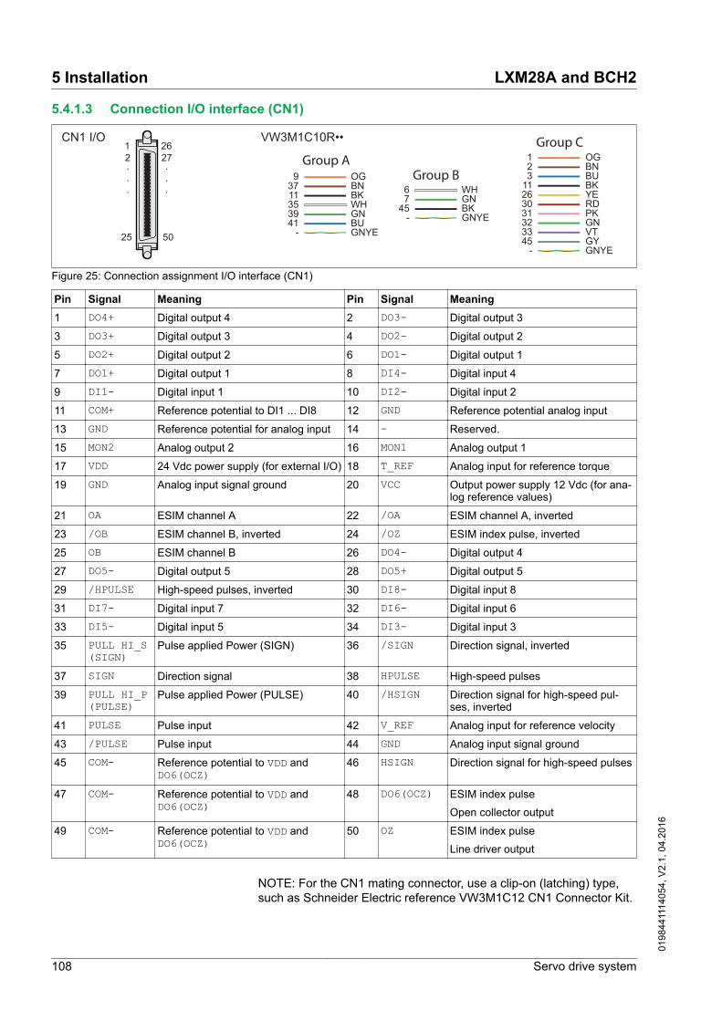
5.4.1.3 Connection I/O interface (CN1)
CN1 I/O VW3M1C10R••1 26
25 50
2 27...
.
.
.9
37
3941
-
3511
OGBN
GNBUGNYE
WHBK
Group A
67
45-
WHGNBKGNYE
Group B12
263031323345
-
113
OGBN
YERDPKGNVTGYGNYE
BKBU
Group C
Figure 25: Connection assignment I/O interface (CN1)
Pin Signal Meaning Pin Signal Meaning1 DO4+ Digital output 4 2 DO3- Digital output 3
3 DO3+ Digital output 3 4 DO2- Digital output 2
5 DO2+ Digital output 2 6 DO1- Digital output 1
7 DO1+ Digital output 1 8 DI4- Digital input 4
9 DI1- Digital input 1 10 DI2- Digital input 2
11 COM+ Reference potential to DI1 ... DI8 12 GND Reference potential analog input
13 GND Reference potential for analog input 14 - Reserved.
15 MON2 Analog output 2 16 MON1 Analog output 1
17 VDD 24 Vdc power supply (for external I/O) 18 T_REF Analog input for reference torque
19 GND Analog input signal ground 20 VCC Output power supply 12 Vdc (for ana-log reference values)
21 OA ESIM channel A 22 /OA ESIM channel A, inverted
23 /OB ESIM channel B, inverted 24 /OZ ESIM index pulse, inverted
25 OB ESIM channel B 26 DO4- Digital output 4
27 DO5- Digital output 5 28 DO5+ Digital output 5
29 /HPULSE High-speed pulses, inverted 30 DI8- Digital input 8
31 DI7- Digital input 7 32 DI6- Digital input 6
33 DI5- Digital input 5 34 DI3- Digital input 3
35 PULL HI_S(SIGN)
Pulse applied Power (SIGN) 36 /SIGN Direction signal, inverted
37 SIGN Direction signal 38 HPULSE High-speed pulses
39 PULL HI_P(PULSE)
Pulse applied Power (PULSE) 40 /HSIGN Direction signal for high-speed pul-ses, inverted
41 PULSE Pulse input 42 V_REF Analog input for reference velocity
43 /PULSE Pulse input 44 GND Analog input signal ground
45 COM- Reference potential to VDD andDO6(OCZ)
46 HSIGN Direction signal for high-speed pulses
47 COM- Reference potential to VDD andDO6(OCZ)
48 DO6(OCZ) ESIM index pulse
Open collector output
49 COM- Reference potential to VDD andDO6(OCZ)
50 OZ ESIM index pulse
Line driver output
NOTE: For the CN1 mating connector, use a clip-on (latching) type,such as Schneider Electric reference VW3M1C12 CN1 Connector Kit.
5 Installation LXM28A and BCH2
108 Servo drive system
0198
4411
1405
4, V
2.1,
04.
2016

WARNINGUNINTENDED OPERATION
Wire and configure the system in such a way that unintended move-ments cannot occur in the case of wire breaks or grounding errors ofa signal wire.
Failure to follow these instructions can result in death, seriousinjury, or equipment damage.
Analog inputs and outputs Example of reference value via analog input:
GND
Servo Drive
13
6kΩ
18 (T-REF)
+
-+/-10V
~
Example of analog output:
Servo Drive
13
GND
MON1 16(MON2) (15)
±8V1mA max.
>10kΩ
LXM28A and BCH2 5 Installation
Servo drive system 109
0198
4411
1405
4, V
2.1,
04.
2016

Pulse input (open collector, logictype 2) WARNING
UNINTENDED EQUIPMENT OPERATION
Do not connect an external, 24 Vdc power supply to the VDD con-nection of the I/O interface (CN1) connector.
Failure to follow these instructions can result in death, seriousinjury, or equipment damage.
Example of pulse input (open collector) with internal power supply(logic type 2).
VDD 24VdcServo Drive
COM-
17
45
37 (41)
36(43)
35 (39)
Pull-hi_S(Pull-hi_P)
SIGN(PULSE)
SIGN(PULSE)
51Ω
51Ω
LogicController
Figure 26: Example of pulse input (open collector) with internal power supply(logic type 2).
Example of pulse input (open collector) with external power supply(logic type 2).
VDDV+
Q.x
V-
24VdcServo Drive
COM-
17
45
37 (41)
36(43)
35 (39)
Pull-hi_S(Pull-hi_P)
SIGN(PULSE)
SIGN(PULSE)
51Ω
51Ω
LogicController
Figure 27: Example of pulse input (open collector) with external power supply(logic type 2).
5 Installation LXM28A and BCH2
110 Servo drive system
0198
4411
1405
4, V
2.1,
04.
2016

Pulse input (open collector, logictype 1) WARNING
UNINTENDED EQUIPMENT OPERATION
Do not connect an external, 24 Vdc power supply to the VDD con-nection of the I/O interface (CN1) connector.
Failure to follow these instructions can result in death, seriousinjury, or equipment damage.
Example of pulse input (open collector) with internal power supply(logic type 1).
Servo DriveLogicController
COM-
0Vdc45
37 (41)
36(43)
35 (39)
Pull-hi_S(Pull-hi_P)
SIGN(PULSE)
SIGN(PULSE)
51Ω
51Ω
24VdcVDD 24Vdc
17
Figure 28: Example of pulse input (open collector) with internal power supply(logic type 1).
Example of pulse input (open collector) with external power supply(logic type 1).
Servo DriveLogicController
COM-
0Vdc45
37 (41)
36(43)
35 (39)
Pull-hi_S(Pull-hi_P)
SIGN(PULSE)
SIGN(PULSE)
51Ω
51Ω
VDD 24Vdc17
Figure 29: Example of pulse input (open collector) with external power supply(logic type 1).
LXM28A and BCH2 5 Installation
Servo drive system 111
0198
4411
1405
4, V
2.1,
04.
2016

Pulse input (line driver) Example of pulse input (line driver).
Servo Drive
37(41)
36(43)
SIGN(PULSE)
SIGN(PULSE)PULSE
SIGN
RS422RS485
line driver
51Ω
51Ω
Figure 30: Pulse input (line driver)
Observe the polarity of the input.
High-speed pulses Example of high-speed pulse input (line driver).
Servo Drive
38
29
HSIGN
HPULSE
HSIGN
HPULSE
GND GND13
40
46
120Ω
AM26LV32
AM26LV32
120Ω
RS422RS485
line driver
RS422RS485
line driver
High Pulse
High Sign
Figure 31: High-speed pulses
Connect the cable shield to the ground connection of the logic control-ler and to the ground connection of the drive.
NOTE: Ensure that the grounding of the cable is to the equipotentialground plane of your system.
5 Installation LXM28A and BCH2
112 Servo drive system
0198
4411
1405
4, V
2.1,
04.
2016

Wiring of the digital outputs (logictype 2)
Example of digital outputs DO1 ... DO5 with internal power supply (logictype 2):
DO1+...DO5+
DO1-...DO5-
COM-
VDD24VdcServo Drive
Example of digital outputs DO1 ... DO5 with external power supply(logic type 2):
DO1+...DO5+
DO1-...DO5-
Servo Drive
+
-24Vdc
~
LXM28A and BCH2 5 Installation
Servo drive system 113
0198
4411
1405
4, V
2.1,
04.
2016

Example of digital output DO6 (OCZ) with internal power supply (logictype 2):
DO6(OCZ)
VDD24VdcServo Drive
COM-
Example of digital output DO6 (OCZ) with external power supply (logictype 2):
DO6(OCZ)
Servo Drive
+
-24Vdc
~COM-
Inductive loads using DC voltages may damage the signal outputs. Aprotection circuit is required to protect the signal outputs againstinductive loads.
CAUTIONOUTPUT CIRCUIT DAMAGE DUE TO INDUCTIVE LOADS
Use an appropriate external protective circuit or device to reduce therisk of inductive direct current load damage.
Failure to follow these instructions can result in injury or equip-ment damage.
A diode can be used to protect the signal outputs against inductiveloads. Use a diode with the following ratings:Reverse withstand voltage: Voltage of signal output * 10 Forward current: Higher than the load current
5 Installation LXM28A and BCH2
114 Servo drive system
0198
4411
1405
4, V
2.1,
04.
2016

Wiring of the digital outputs (logictype 1)
Example of digital outputs DO1 ... DO5 with internal power supply (logictype 1):
DO1+...DO5+
DO1-...DO5-
COM-
VDD24VdcServo Drive
Example of digital outputs DO1 ... DO5 with external power supply(logic type 1):
DO1+...DO5+
DO1-...DO5-
Servo Drive
+
-24Vdc
~
Inductive loads using DC voltages may damage the signal outputs. Aprotection circuit is required to protect the signal outputs againstinductive loads.
CAUTIONOUTPUT CIRCUIT DAMAGE DUE TO INDUCTIVE LOADS
Use an appropriate external protective circuit or device to reduce therisk of inductive direct current load damage.
Failure to follow these instructions can result in injury or equip-ment damage.
A diode can be used to protect the signal outputs against inductiveloads. Use a diode with the following ratings:Reverse withstand voltage: Voltage of signal output * 10 Forward current: Higher than the load current
LXM28A and BCH2 5 Installation
Servo drive system 115
0198
4411
1405
4, V
2.1,
04.
2016

Wiring of the digital inputs (logictype 2) WARNING
UNINTENDED EQUIPMENT OPERATION
Do not connect an external, 24 Vdc power supply to the VDD con-nection of the I/O interface (CN1) connector.
Failure to follow these instructions can result in death, seriousinjury, or equipment damage.
Use a relay or an open collector output (NPN transistor) for the inputsignal.
Example of digital input (logic type 2) with internal power supply:
DI1-...DI8-
COM-
VDD 24VdcServo Drive
COM+
Example of digital input (logic type 2) with external power supply:
DI1-...DI8-
Servo Drive
COM++
-24Vdc
~
5 Installation LXM28A and BCH2
116 Servo drive system
0198
4411
1405
4, V
2.1,
04.
2016

Wiring of the digital inputs (logictype 1) WARNING
UNINTENDED EQUIPMENT OPERATION
Do not connect an external, 24 Vdc power supply to the VDD con-nection of the I/O interface (CN1) connector.
Failure to follow these instructions can result in death, seriousinjury, or equipment damage.
Use a relay or an open collector output (PNP transistor) for the inputsignal.
Example of digital input with internal power supply (logic type 1):
DI1-...DI8-
COM-
VDD 24VdcServo Drive
COM+
Example of digital input with external power supply (logic type 1):
DI1-...DI8-
Servo Drive
COM+
+
-24Vdc
~
LXM28A and BCH2 5 Installation
Servo drive system 117
0198
4411
1405
4, V
2.1,
04.
2016

Encoder output signal Example of encoder output signal Line Driver.
OA OB OZ 21 25 50
OA OB OZ 22 23 24
Servo Drive
AM26LV31
125Ω
Max. 30mA
Example of encoder output signal, high-speed optocoupler.
OA OB OZ 21 25 50
OA OB OZ 22 23 24
Servo Drive
100Ω
Max. 30mA
Min. 2.2VdcMax. 3.3Vdc
AM26LV31
5 Installation LXM28A and BCH2
118 Servo drive system
0198
4411
1405
4, V
2.1,
04.
2016
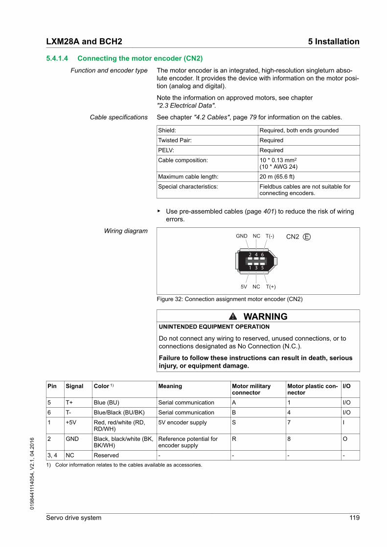
5.4.1.4 Connecting the motor encoder (CN2)Function and encoder type The motor encoder is an integrated, high-resolution singleturn abso-
lute encoder. It provides the device with information on the motor posi-tion (analog and digital).
Note the information on approved motors, see chapter"2.3 Electrical Data".
Cable specifications See chapter "4.2 Cables", page 79 for information on the cables.
Shield: Required, both ends grounded
Twisted Pair: Required
PELV: Required
Cable composition: 10 * 0.13 mm2 (10 * AWG 24)
Maximum cable length: 20 m (65.6 ft)
Special characteristics: Fieldbus cables are not suitable forconnecting encoders.
▶ Use pre-assembled cables (page 401) to reduce the risk of wiringerrors.
Wiring diagramCN2 E
2 64
1 53
GND NC T(-)
5V NC T(+)
Figure 32: Connection assignment motor encoder (CN2)
WARNINGUNINTENDED EQUIPMENT OPERATION
Do not connect any wiring to reserved, unused connections, or toconnections designated as No Connection (N.C.).
Failure to follow these instructions can result in death, seriousinjury, or equipment damage.
Pin Signal Color 1) Meaning Motor militaryconnector
Motor plastic con-nector
I/O
5 T+ Blue (BU) Serial communication A 1 I/O
6 T- Blue/Black (BU/BK) Serial communication B 4 I/O
1 +5V Red, red/white (RD,RD/WH)
5V encoder supply S 7 I
2 GND Black, black/white (BK,BK/WH)
Reference potential forencoder supply
R 8 O
3, 4 NC Reserved - - - -1) Color information relates to the cables available as accessories.
LXM28A and BCH2 5 Installation
Servo drive system 119
0198
4411
1405
4, V
2.1,
04.
2016

Connecting the motor encoder ▶ Verify that wiring, cables and connected interface meet the PELVrequirements.
▶ Note the information on EMC, see chapter"4.1 Electromagnetic compatibility (EMC)". Use equipotential bond-ing conductors for equipotential bonding.
▶ Connect the connector to CN2 Encoder.▶ Verify that the connector locks snap in properly at the housing.
Route the cables from the motor and the encoder to the device (start-ing from the motor). Due to the pre-assembled connectors, this direc-tion is often faster and easier.
5.4.1.5 Connection PC (CN3)The commissioning interface (CN3) is an RS485 connection, suppor-ted on an RJ45 connector. If the PC used to connect to the commis-sioning interface has an RS485 port, typically supported on a DB9connector, you can connect it to this connector (RJ45 / DB9 cable).Otherwise, you can use the USB port of the PC with a USB to RS485converter.
The commissioning interface may only be used for a point-to-pointconnection, but not for a point-to-multipoint connection (RS485 net-work).
If the commissioning interface at the product is directly connected toan Ethernet interface at the PC, the PC interface may be damagedand rendered inoperable.
NOTICEINOPERABLE EQUIPMENT
Do not directly connect an Ethernet interface to the commissioninginterface of this product.
Failure to follow these instructions can result in equipmentdamage.
Connecting a PC A PC with the commissioning software LXM28 DTM Library can beconnected for commissioning. The PC is connected via a bidirectionalUSB/RS485 converter, see chapter Accessories, page 401.
Cable specifications See chapter "4.2 Cables", page 79 for information on the cables.
Shield: Required, both ends grounded
Twisted Pair: Required
PELV: Required
Cable composition: 8 * 0.25 mm2 (8 * AWG 22)
Maximum cable length: 100 m (328 ft)
Special characteristics: -
5 Installation LXM28A and BCH2
120 Servo drive system
0198
4411
1405
4, V
2.1,
04.
2016

Wiring diagramCN3 Modbus
8
1
Figure 33: Wiring diagram PC with commissioning software
Pin Signal Meaning I/O1 ... 3 - Reserved -
4 MOD_D1 1) Bidirectional transmit/receive signal RS485 level
5 MOD_D0 1) Bidirectional transmit/receive signal, inverted RS485 level
6 ... 7 - Reserved -
8 and con-nector hous-ing
SHLD Functional ground / shield - internally connected to groundpotential of the drive
-
1) No polarization.
WARNINGUNINTENDED EQUIPMENT OPERATION
Do not connect any wiring to reserved, unused connections, or toconnections designated as No Connection (N.C.).
Failure to follow these instructions can result in death, seriousinjury, or equipment damage.
▶ Verify that the connector locks snap in properly at the housing.
LXM28A and BCH2 5 Installation
Servo drive system 121
0198
4411
1405
4, V
2.1,
04.
2016

5.4.1.6 Connection CAN (CN4)Function The device is suitable for connection to CANopen and CANmotion.
A CAN bus connects multiple devices via a bus cable. Each networkdevice can transmit and receive messages. Data between networkdevices is transmitted serially.
Each network device must be configured before it can be operated onthe network. The device is assigned a unique 7 bit node address(node ID) between 1 (01h) and 127 (7Fh). The address is set duringcommissioning.
The baud rate must be the same for all devices in the fieldbus.
Cable specifications See chapter "4.2 Cables", page 79 for information on the cables.
Shield: Required, both ends grounded
Twisted Pair: Required
PELV: Required
Cable composition for cables withRJ45 connectors 1):
8 * 0.14 mm2 (AWG 24)
Cable composition with D-SUB con-nectors:
2 * 0.25 mm2, 2 * 0.20 mm2
(2 * AWG 22, 2 * AWG 24)
Cross section 0.20 mm2 (AWG 24) forCAN level, cross section 0.25 mm2
(AWG 22) for reference potential.1) Cables with RJ45 connectors may only be used inside of control cabinets.
▶ Use equipotential bonding conductors, see page 79.▶ Use pre-assembled cables (page 402) to reduce the risk of wiring
errors.
5 Installation LXM28A and BCH2
122 Servo drive system
0198
4411
1405
4, V
2.1,
04.
2016

Connectors D-SUB and RJ45 Usually, a cable with D-Sub connectors is used for CAN fieldbus con-nection in the field. Inside control cabinets, connections with RJ45cables have the benefit of easier and faster wiring. In the case of CANcables with RJ45 connectors, the maximum permissible bus length isreduced by 50%.
Multiple-port taps can be used to connect an RJ45 system inside thecontrol cabinet to a D-Sub system in the field, see the figure below.The trunk line is connected to the multiple-port tap by means of screwterminals; the devices are connected by means of pre-assembledcables. See chapter"12.6 CANopen connectors, distributors, terminating resistors".
RJ45
D-SUB
32
2
6
2
4
5
1
Figure 34: Connection of RJ45 CAN in the control cabinet to the field
(1) Devices with RJ45 CAN connection in the control cabinet(2) CANopen cables with RJ45 connectors(3) Connection cables between device and tap, for example
TCSCCN4F3M3T for tap TSXCANTDM4(4) Tap in the control cabinet, for example TSXCANTDM4 as D-
SUB four-port tap or VW3CANTAP2 as RJ45 tap(5) Fieldbus cable (trunk line) to the bus devices outside of the
control cabinet, connected to the tap by means of screw ter-minals. Cross section 0.20 mm2 (AWG 24) for CAN level, cross sec-tion 0.25 mm2 (AWG 22) for reference potential.
(6) Terminating resistor 120 Ω RJ45 (TCSCAR013M120)
LXM28A and BCH2 5 Installation
Servo drive system 123
0198
4411
1405
4, V
2.1,
04.
2016

Maximum bus length CAN The maximum bus length depends on the selected baud rate. The fol-lowing table shows the maximum overall length of the CAN bus in thecase of cables with D-SUB connectors.
Baud rate Maximum bus length125 kbit/s 500 m (1640 ft)
250 kbit/s 250 m (820 ft)
500 kbit/s 100 m (328 ft)
1000 kbit/s 20 m (65.6 ft) 1)
1) According to the CANopen specification, the maximum bus length is 40 m. How-ever, in practice, limiting the length to 20 m reduces communication errors causedby external interference.
At a baud rate of 1 Mbit/s, the drop lines are limited to 0.3 m (0.98 ft).
Terminating resistors Both ends of a CAN bus line must be terminated. A 120 Ω terminatingresistor between CAN_L and CAN_H is used for this purpose.
Connectors with integrated terminating resistors are available asaccessories, see chapter"12.6 CANopen connectors, distributors, terminating resistors", page402.
Wiring diagram CN4 CAN
1
8
8
1
Figure 35: Wiring diagram CN4 CANopen
Pin Signal Meaning I/O1 CAN_H CAN interface CAN level
2 CAN_L CAN interface CAN level
3 CAN_0V Reference potential CAN -
4 ... 5 - Reserved -
6 and connectorhousing
SHLD Functional ground / shield - internally connected to groundpotential of the drive
-
7 CAN_0V Reference potential CAN -
8 - Reserved -
WARNINGUNINTENDED EQUIPMENT OPERATION
Do not connect any wiring to reserved, unused connections, or toconnections designated as No Connection (N.C.).
Failure to follow these instructions can result in death, seriousinjury, or equipment damage.
5 Installation LXM28A and BCH2
124 Servo drive system
0198
4411
1405
4, V
2.1,
04.
2016

Connecting CANopen ▶ Connect the CANopen cable to CN4 (pins 1, 2 and 3) with an RJ45connector. Note the information on using cables with RJ45 connec-tors.
▶ Verify that the connector locks snap in properly at the housing.
Equipotential bonding conductors Potential differences can result in excessive currents on the cableshields. Use equipotential bonding conductors to reduce currents onthe cable shields.
WARNINGUNINTENDED EQUIPMENT OPERATION
• Ground cable shields for all fast I/O, analog I/O, and communica-tion signals at a single point. 1)
• Route communications and I/O cables separately from powercables.
Failure to follow these instructions can result in death, seriousinjury, or equipment damage.
1) Multipoint grounding is permissible if connections are made to an equipotentialground plane dimensioned to help avoid cable shield damage in the event of powersystem short-circuit currents.
The equipotential bonding conductor must be rated for the maximumcurrent. The following conductor cross sections can be used:
• 16 mm2 (AWG 4) for equipotential bonding conductors up to alength of 200 m (656 ft)
• 20 mm2 (AWG 4) for equipotential bonding conductors with alength of more than 200 m (656 ft)
Terminating resistors Both ends of a CAN bus line must be terminated. A 120 Ω terminatingresistor between CAN_L and CAN_H is used for this purpose.
LXM28A and BCH2 5 Installation
Servo drive system 125
0198
4411
1405
4, V
2.1,
04.
2016

5.4.1.7 Connection power stage supply and controller supply (CN5)This product has a leakage current greater than 3.5 mA. If the protec-tive ground connection is interrupted, a hazardous touch current mayflow if the housing is touched.
DANGERINSUFFICIENT GROUNDING
• Use a protective ground conductor at with least 10 mm2 (AWG 6)or two protective ground conductors with the cross section of theconductors supplying the power terminals.
• Verify compliance with all local and national electrical coderequirements as well as all other applicable regulations withrespect to grounding of all equipment.
Failure to follow these instructions will result in death or seri-ous injury.
WARNINGINSUFFICIENT PROTECTION AGAINST OVERCURRENT
• Use the external fuses specified in "Technical data".• Do not connect the product to a supply mains whose short-circuit
current rating (SCCR) exceeds the value specified in the chapter"Technical Data".
Failure to follow these instructions can result in death, seriousinjury, or equipment damage.
WARNINGINCORRECT MAINS VOLTAGE
Verify that the product is approved for the mains voltage beforeapplying power and configuring the product.
Failure to follow these instructions can result in death, seriousinjury, or equipment damage.
The products are intended for industrial use and may only be operatedwith a permanently installed connection.
Prior to connecting the device, verify the approved mains types, seechapter "2.3.1 Electrical data drive", page 40.
Cable specifications Observe the required cable properties, see page 79, and the informa-tion on electromagnetic compatibility (EMC), see page 77.
Shield: -
Twisted Pair: -
PELV: -
Cable composition: The conductors must have a suffi-ciently large cross section so that thefuse at the mains connection can tripif required.
Maximum cable length: 3 m (9.84 ft)
Special characteristics: -
5 Installation LXM28A and BCH2
126 Servo drive system
0198
4411
1405
4, V
2.1,
04.
2016

Properties of the terminals The terminals are approved for stranded conductors and solid conduc-tors. Use wire ferrules, if possible.
LXM28∙ UA5, U01, U02,U04, U07, U10,U15
U20, U30, U45
Connection cross sec-tion
mm2 (AWG)
0.75 ... 2.5(20 ... 14)
0.75 ... 6(20 ... 10)
Stripping length mm(in)
8 ... 9 15
Prerequisites for connecting thepower stage supply
Note the following information:
• Use upstream mains fuses. See chapter"2.3.1 Electrical data drive" for information on fuse types and fuseratings.
• Observe the EMC requirements. Where required, use surge arrest-ers and mains reactors.
• If the length of the mains cable between the external mains filterand the drive exceeds 200 mm (7.87 in), it must be shielded andgrounded at both ends.
• See page "2.6 Conditions for UL 508C" for a UL-compliant design.• Use a protective ground conductor with at least 10 mm2 (AWG 6)
or two protective ground conductors with the cross section of theconductors supplying the power terminals. Verify compliance withall local and national electrical code requirements as well as allother applicable regulations with respect to grounding of all equip-ment.
DANGERELECTRIC SHOCK CAUSED BY INSUFFICIENT GROUNDING
• Verify compliance with all local and national electrical coderequirements as well as all other applicable regulations withrespect to grounding of the entire drive system.
• Ground the drive system before applying voltage.• Do not use conduits as protective ground conductors; use a pro-
tective ground conductor inside the conduit.• The cross section of the protective ground conductor must com-
ply with the applicable standards.• Do not consider cable shields to be protective ground conductors.
Failure to follow these instructions will result in death or seri-ous injury.
LXM28A and BCH2 5 Installation
Servo drive system 127
0198
4411
1405
4, V
2.1,
04.
2016

Connection power stage supply ~220V
TSR
L1L2
Figure 36: Wiring diagram power stage supply
▶ Verify the type of mains. See chapter "2.3.1 Electrical data drive"for the approved types of mains.
▶ Connect the mains cable (Figure 36).▶ Verify that the connector locks snap in properly at the housing.
Wiring diagram for devices thatcan be connected via a single
phase or three phases
Drives with a continuous power from 50 W to 1500 W can be connec-ted via a single phase or via three phases. Drives with a continuouspower of more than 1500 W must be connected via three phases.
L1
L2
Servo Drive
M3~
+
-24Vdc
S
R
T
CN1
ALRM_RY
MC
DO5+(28)
VU
W
DO5-(27)
~
I> I> I>
Q1
ON
OFF
Figure 37: Wiring diagram for devices that can be connected via a single phase or three phases
5.4.1.8 Connection DC bus (CN6)Incorrect use of the DC bus may permanently damage the driveseither immediately or over time.
WARNINGDESTRUCTION OF SYSTEM COMPONENTS AND LOSS OF CONTROL
Verify that all requirements for using the DC bus are met.
Failure to follow these instructions can result in death, seriousinjury, or equipment damage.
5 Installation LXM28A and BCH2
128 Servo drive system
0198
4411
1405
4, V
2.1,
04.
2016

This and other important information can be found in the "LXM28 -Common DC bus - Application note". If you wish to take advantage ofDC bus sharing, you must first consult the LXM28 - Common DC bus -Application note for important safety-related information.
Requirements for use The requirements and limit values for parallel connection of multipledevices via the DC bus can be found on www.schneider-electric.comin the form of an application note (see chapter " Related Documents").If there are any issues or questions related to obtaining the CommonDC bus Application Note, consult your local Schneider-Electric repre-sentative.
LXM28A and BCH2 5 Installation
Servo drive system 129
0198
4411
1405
4, V
2.1,
04.
2016

5.4.1.9 Connection braking resistor (CN7)An insufficiently rated braking resistor can cause overvoltage on theDC bus. Overvoltage on the DC bus causes the power stage to bedisabled. The motor is no longer actively decelerated.
WARNINGUNINTENDED EQUIPMENT OPERATION
• Verify that the braking resistor has a sufficient rating by perform-ing a test run under maximum load conditions.
• Verify that the parameter settings for the braking resistor are cor-rect.
Failure to follow these instructions can result in death, seriousinjury, or equipment damage.
Further information on the subject PageTechnical data braking resistor 49
Rating the braking resistor 92
Order data for external braking resistors (accessory) 401
Internal braking resistor A braking resistor is integrated in the device to absorb braking energy.The device is shipped with the internal braking resistor active.
External braking resistor
An external braking resistor is required for applications in which themotor must be decelerated quickly and the internal braking resistorcannot absorb the excess braking energy.
Selection and rating of the external braking resistor are described inchapter "4.6 Rating the braking resistor", page 92. For suitable brakingresistors, see chapter "12 Accessories and spare parts", page 406.
Cable specifications See chapter "4.2 Cables", page 79 for information on the cables.
Shield: Required, both ends grounded
Twisted Pair: -
PELV: -
Cable composition: Minimum conductor cross section:Same cross section as power stagesupply, see page 126.
The conductors must have a suffi-ciently large cross section so that thefuse at the mains connection can tripif required.
Maximum cable length: 3 m (9.84 ft)
Special characteristics: Temperature resistance
The braking resistors listed in chapter"12 Accessories and spare parts" have a 3-wire, temperature-resistantcable with a length of 0.75 m (2.46 ft) to 3 m (9.84 ft).
Properties of the terminals CN7 The terminals are approved for stranded conductors and solid conduc-tors. Use wire ferrules, if possible.
5 Installation LXM28A and BCH2
130 Servo drive system
0198
4411
1405
4, V
2.1,
04.
2016

LXM28∙ UA5, U01, U02,U04, U07, U10,U15
U20, U30, U45
Connection cross sec-tion
mm2 (AWG)
0.75 ... 2.5(20 ... 14)
0.75 ... 6(20 ... 10)
Stripping length mm(in)
8 ... 9 15
The terminals are approved for fine-stranded conductors and solidconductors. Observe the maximum permissible connection cross sec-tion. Take into account the fact that wire ferrules increase the conduc-tor cross section.
Wire ferrules: If you use wire ferrules, use only wire ferrules with col-lars for these terminals.
Wiring diagramPBe
PA/+PBi
PBe
PA/+PBi
1 2
Figure 38: Wiring diagram internal or external braking resistor
(1) Internal braking resistor activated(2) Connection external braking resistor
Connecting the external brakingresistor
▶ Remove power from all supply voltages. Observe the safetyinstructions concerning electrical installation.
▶ Verify that no voltages are present (safety instructions).▶ Ground the ground connection (PE) of the braking resistor.▶ Connect the external braking resistor to the device.▶ Connect a large surface area of the cable shield to the central
grounding point of your system.
LXM28A and BCH2 5 Installation
Servo drive system 131
0198
4411
1405
4, V
2.1,
04.
2016

DANGERHAZARD DUE TO ELECTRIC SHOCK, EXPLOSION OR ARC FLASH
• Before performing work on the drive system:
- Disconnect all power from all equipment including connecteddevices prior to removing any covers or doors, or installing orremoving any accessories, hardware, cables, or wires.
- Place a "Do Not Turn On" or equivalent hazard label on allpower switches.
- Lock all power switches in the open (non-energized) position.- Wait 15 minutes to allow the DC bus capacitors to discharge.- Measure the voltage on the DC bus with a properly rated volt-
age sensing device as per the instructions in the presentdocument and verify that the voltage is less than 42.4 Vdc.
- Do not assume that the DC bus is voltage-free when the DCbus LED is off.
• Do not touch any connectors, contacts, terminals, unshieldedcomponents or printed circuit boards while, or if you suspect that,the equipment is under power.
• Use only electrically insulated tools.• Block the motor shaft to prevent rotation prior to performing any
type of work on the drive system.• Insulate both ends of unused conductors of the motor cable to
help prevent AC voltage from coupling to unused conductors inthe motor cable.
• Do not create a short-circuit across the DC bus terminals or theDC bus capacitors.
• Replace and secure all covers, accessories, hardware, cables,and wires and confirm that a proper ground connection existsbefore applying power to the unit.
• Use only the specified voltage when operating this equipment andany associated products.
Failure to follow these instructions will result in death or seri-ous injury.
5 Installation LXM28A and BCH2
132 Servo drive system
0198
4411
1405
4, V
2.1,
04.
2016

5.4.1.10 Connecting the motor phases (CN8)High voltages may be present at the motor connection. The motoritself generates voltage when the motor shaft is rotated. AC voltagecan couple voltage to unused conductors in the motor cable.
DANGERELECTRIC SHOCK
• Verify that no voltage is present prior to performing any type ofwork on the drive system.
• Block the motor shaft to prevent rotation prior to performing anytype of work on the drive system.
• Insulate both ends of unused conductors of the motor cable.• Supplement the motor cable grounding conductor with an addi-
tional protective ground conductor to the motor housing.• Verify compliance with all local and national electrical code
requirements as well as all other applicable regulations withrespect to grounding of all equipment.
Failure to follow these instructions will result in death or seri-ous injury.
NOTE: Incorrect wiring of the motor connection may cause live wiresto be exposed outside of the motor connector below the HMI.
DANGERELECTRIC SHOCK CAUSED BY INCORRECT WIRING
• Verify that the protective ground connection (PE) of the device isconnected to ground.
• Do not remove the wire ferrule (cable end) from the protectiveground terminal (PE) of the motor connector until you are pre-pared to wire the protective ground conductor of the motor to theprotective ground terminal (PE) of the motor connector.
• Verify that no bare metal of the wires is exposed outside of themotor connector housing when wiring the motor connector.
• Verify that the wires cannot come loose in the terminals of themotor connector due to vibration or other influences.
Failure to follow these instructions will result in death or seri-ous injury.
Drive systems may perform unintended movements if unapprovedcombinations of drive and motor are used. Even if motors are similar,different adjustment of the encoder system may be a source of haz-ards. Even if the connectors for motor connection and encoder con-nection match mechanically, this does not imply that the motor isapproved for use.
WARNINGUNINTENDED MOVEMENT
Only use approved combinations of drive and motor.
Failure to follow these instructions can result in death, seriousinjury, or equipment damage.
LXM28A and BCH2 5 Installation
Servo drive system 133
0198
4411
1405
4, V
2.1,
04.
2016

For the list of the combinations see chapter"1.5 Permissible product combinations".
Route the cables from the motor and the encoder to the device (start-ing from the motor). Due to the pre-assembled connectors, this direc-tion is often faster and easier.
Cable specifications See chapter "4.2 Cables", page 79 for information on the cables.
Shield: Required, both ends grounded
Twisted Pair: -
PELV: The wires for the holding brake mustbe PELV-compliant.
Cable composition: 3 wires for motor phases
The conductors must have a suffi-ciently large cross section so that thefuse at the mains connection can tripif required.
Maximum cable length: Depends on the required limit valuesfor conducted interference. Category C3: 50 m (164 ft)
Special characteristics: Contains wires for the temperaturesensor
Note the following information:
• You may only connect the original motor cable.• If you do not connect the wires at the motor end, you must isolate
each wire individually (inductive voltages).▶ Use pre-assembled cables (page 401) to reduce the risk of wiring
errors.
Properties of the terminals CN8 The terminals are approved for stranded conductors and solid conduc-tors. Use wire ferrules, if possible.
LXM28∙ UA5, U01, U02,U04, U07, U10,U15
U20, U30, U45
Connection cross sec-tion
mm2 (AWG)
0.75 ... 2.5(20 ... 14)
0.75 ... 6(20 ... 10)
Stripping length mm(in)
8 ... 9(0.31 ... 0.35)
15(0.59)
Monitoring The drive monitors the motor phases for:
• Short circuit between the motor phases• Short circuit between the motor phases and ground
(applies to drives above size 1)
Short circuits between the motor phases and the DC bus, the brakingresistor or the holding brake wires are not detected.
When a short-circuit is detected, power is removed by disabling thepower stage. The firmware reports error AL001. Once you haveresolved the issue of the over-current, you can re-enable the powerstage of the drive.
NOTE: After three successive unsuccessful retries of resetting thepower stage, the reset will be blocked for a minimum of one minute.
5 Installation LXM28A and BCH2
134 Servo drive system
0198
4411
1405
4, V
2.1,
04.
2016

Wiring diagram motorPE
WVU M
3~
Figure 39: Wiring diagram motor
Connection Meaning Color 1) (IEC 757)
U Motor phase RD
V Motor phase WH
W Motor phase BK
PE Protective ground conduc-tor
GN/YE
1) Color information relates to the cables available as accessories.
Connecting the motor cable ▶ Note the information on EMC, see chapter"4.1 Electromagnetic compatibility (EMC)".
▶ Connect the motor phases and protective ground conductor toCN8. Verify that the connections U, V, W and PE (ground) match atthe motor and the device.
▶ Verify that the connector locks snap in properly at the housing.
LXM28A and BCH2 5 Installation
Servo drive system 135
0198
4411
1405
4, V
2.1,
04.
2016

5.4.1.11 Holding brake connectionThe holding brake in the motor has the task of holding the motor posi-tion when the power stage is disabled. The holding brake is not asafety function and not a service brake.
A motor with a holding brake requires a suitable holding brake control-ler which releases the brake when the power stage is enabled andlocks the motor shaft when the power stage is disabled.
The holding brake is connected to one of the digital outputs DO1 ...DO5. The signal output function BRKR must be assigned to the digitaloutput to which the holding brake is connected. The signal outputfunction BRKR releases the holding brake when the power stage isenabled. When the power stage is disabled, the holding brake is re-applied.
The factory settings for the signal outputs depend on the operatingmode, see chapter "7.4.3 Default presets of the signal outputs".Depending on the operating mode, the signal output function is eitherassigned to the digital output DO4 or not assigned at all. When youreset the drive to the factory settings with P2-08 = 10, the assign-ments of the signal output functions are also reset to the factory set-tings.
When you switch the operating mode using the parameter P1-01 orthe signal input functions V-Px and V-T, the signal output functionsmay also be reset to the factory settings for the new operating mode.If you use the setting D = 0 of parameter P1-01, the assignment of thesignal output functions remains the same in the new operating mode.
Resetting the drive to the factory settings or switching the operatingmode can modify the assignment of the signal output functions in sucha way that the holding brake is released unintentionally.
WARNINGUNINTENDED EQUIPMENT OPERATION
• Verify that the digital output to which you have assigned the sig-nal output function BRKR has been properly wired and config-ured.
• Before switching to a different operating mode, verify that the sig-nal output function BRKR for the holding brake will not beassigned to an incorrect digital output in the new operating mode.
• Before resetting the drive to the factory settings, verify that thesignal output function BRKR for the holding brake will beassigned to the correct digital output or reassign the signal outputfunction BRKR after the factory reset according to the require-ments of your application prior to starting the system.
• In all cases, take all necessary measures to prevent unintendedmovements of the load caused by a release of the holding brake.
Failure to follow these instructions can result in death, seriousinjury, or equipment damage.
5 Installation LXM28A and BCH2
136 Servo drive system
0198
4411
1405
4, V
2.1,
04.
2016

+
-24Vdc
~
Servo Motor
Encoder
Brake
Motor(1)(2)
(2)DO1+...DO5+
DO1-...DO5-COM-
VDD24VdcServo Drive
Figure 40: Example (logic type 2) of wiring the holding brake
(1) Triggering an EMERGENCY STOP should apply the holdingbrake
(2) Flyback diode
LXM28A and BCH2 5 Installation
Servo drive system 137
0198
4411
1405
4, V
2.1,
04.
2016

5.4.1.12 Connection STO (CN9)For important safety information, refer to the chapter"4.5 Safety function STO ("Safe Torque Off")" for the requirements forusing the safety function STO.
Cable specifications - cables out-side of control cabinet Shield: Yes
Twisted Pair: Yes
PELV: Required
Minimum conductor cross section: 2*0.34 mm2 (AWG 22)
Maximum cable length: 30 m (98.4 ft)
Fuse: 4 A
Cable specifications - cables insidecontrol cabinet Shield: No
Twisted Pair: No
PELV: Required
Minimum conductor cross section: 2*0.25 mm2 (AWG 24)
Maximum cable length: 3 m (9.84 ft)
Fuse: 4 A
Properties of the connectionConnectorsHousingCrimp contact
Molex 436450400 1) Molex 430300001 1)
Connection cross section mm2 (AWG)
0.25 ... 0.34(24 ... 22)
1) Or corresponding equivalent.
5 Installation LXM28A and BCH2
138 Servo drive system
0198
4411
1405
4, V
2.1,
04.
2016

Wiring diagram
CN9
STO
STO_24V
STO_0V
JMPC_2
JMPC_1
CN9 STO
1234
Figure 41: Wiring diagram safety function STO
Pin Signal Meaning1 JMPC_1 Jumper connector 1 to be connected to STO_24V if the safety function STO
is not used in your application
2 JMPC_2 Jumper connector 2 to be connected to STO_0V if the safety function STO isnot used in your application
3 STO_0V Safety function STO 0 Vdc input 1)
4 STO_24V Safety function STO 24 Vdc input 1)
1) PELV power supply is required.
Connecting the safety functionSTO
▶ Verify that wiring, cables and connected interfaces meet the PELVrequirements.
▶ Connect the safety function STO in accordance with the specifica-tions in chapter "4.5 Safety function STO ("Safe Torque Off")",page 83.
Deactivating the safety functionSTO
If the safety function STO is not to be used, it must be deactivated.Plug in the jumper for CN9 to bridge pin 1 and pin 4 as well as pin 2and pin 3 to deactivate the safety function STO. The jumper for CN9 isfactory-fitted.
CN9 STO
Figure 42: Deactivating the safety function STO
LXM28A and BCH2 5 Installation
Servo drive system 139
0198
4411
1405
4, V
2.1,
04.
2016

5.4.2 Electrical installation motor
5.4.2.1 Connections and pin assignments
1
2
Figure 43: Connection overview
(1) Encoder connection(2) Motor connection
5 Installation LXM28A and BCH2
140 Servo drive system
0198
4411
1405
4, V
2.1,
04.
2016

Pin assignment motor connection Pin assignments of motor phases and holding brake
1 3
2 4
1 4
2 5
3 6
Figure 44: Motor connection plastic connector (type A and type B)
A
G
F
E
D C
B
C
BA
D
GF
E
Figure 45: Motor connection MIL connector (type C and type D)
PinType A
PinType B
PinType C andD
Signal Meaning Color 1) (IEC 757)
1 1 E U Motor phase U RD
2 2 G V Motor phase V WH
3 4 B W Motor phase W BK
4 5 D PE Protective ground (earth) GN/YE
- 3 F BRAKE_24V Supply voltage holding brake 24 Vdc BU
- 6 A BRAKE_0V Reference potential holding brake0 Vdc
BN
1) Color information relates to the cables available as accessories.
LXM28A and BCH2 5 Installation
Servo drive system 141
0198
4411
1405
4, V
2.1,
04.
2016

Pin assignment encoder connec-tion
Pin assignment of the encoder.
17 4
28 5
39 6
Figure 46: Encoder connection plastic connector (Type A)
A
H G FE
D
CB
NM
L
K
J
T
S R
P
Figure 47: Encoder connection MIL connector (Type B)
PinType A
PinType B
Signal Meaning Color 1) (IEC 757)
1 A T+ DATA BU
4 B T- DATA BU/BK
2 C - Reserved -
3 D - Reserved -
5 F - Reserved -
6 G - Reserved -
7 S DC+5V Supply voltage RD/WH
8 R GND Reference potential BK/WH
9 L Shield Shield BK1) Color information relates to the cables available as accessories.
WARNINGUNINTENDED EQUIPMENT OPERATION
Do not connect any wiring to reserved, unused connections, or toconnections designated as No Connection (N.C.).
Failure to follow these instructions can result in death, seriousinjury, or equipment damage.
Mating connector See chapter "12.2 Connectors and adapters" for suitable mating con-nectors.
5 Installation LXM28A and BCH2
142 Servo drive system
0198
4411
1405
4, V
2.1,
04.
2016

5.4.2.2 Connection of motor and encoderThe motor is designed for operation via a drive. Connecting the motordirectly to AC voltage will damage the motor and can cause fires.
DANGERFIRE HAZARD DUE TO INCORRECT CONNECTION
Only connect the motor to a matching, approved drive.
Failure to follow these instructions will result in death or seri-ous injury.
For the list of the combinations see chapter"1.5 Permissible product combinations".
High voltages may be present at the motor connection. The motoritself generates voltage when the motor shaft is rotated. AC voltagecan couple voltage to unused conductors in the motor cable.
DANGERELECTRIC SHOCK
• Verify that no voltage is present prior to performing any type ofwork on the drive system.
• Block the motor shaft to prevent rotation prior to performing anytype of work on the drive system.
• Insulate both ends of unused conductors of the motor cable.• Supplement the motor cable grounding conductor with an addi-
tional protective ground conductor to the motor housing.• Verify compliance with all local and national electrical code
requirements as well as all other applicable regulations withrespect to grounding of all equipment.
Failure to follow these instructions will result in death or seri-ous injury.
Protective ground conductor con-nection
▶ Ground the motor via a grounding screw if grounding via the flangeand the protective ground conductor of the motor cable is not suffi-cient. Use parts with suitable corrosion protection.
LXM28A and BCH2 5 Installation
Servo drive system 143
0198
4411
1405
4, V
2.1,
04.
2016

Connecting the cables Incorrect installation of the cable may destroy the insulation. Brokenconductors in the cable or improperly connected connectors may bemelted by arcs.
DANGERELECTRIC SHOCK, ARC FLASH AND FIRE CAUSED BY INCORRECTINSTALLATION OF THE CABLE
• Disconnect all power before plugging in or unplugging the con-nectors.
• Verify correct pin assignment of the connectors according to thespecifications in this chapter before connecting the cables.
• Verify that the connectors are properly inserted and locked beforeapplying power.
• Avoid forces or movements of the cable at the cable entries.
Failure to follow these instructions will result in death or seri-ous injury.
▶ Connect the motor cable and the encoder cable to the driveaccording to the wiring diagram of the drive.
▶ If your motor is equipped with a holding brake, follow the instruc-tions in chapter "5.4.2.3 Holding brake connection".
5.4.2.3 Holding brake connectionThe holding brake in the motor has the task of holding the motor posi-tion when the power stage is disabled. The holding brake is not asafety function and not a service brake.
A motor with a holding brake requires a suitable holding brake control-ler which releases the brake when the power stage is enabled andlocks the motor shaft when the power stage is disabled.
See chapter "5.4.1.11 Holding brake connection" for additional infor-mation.
As a result of damage to the insulation of the motor cable, mains volt-age may get to the wires for the holding brake.
DANGERELECTRICAL SHOCK CAUSED BY DAMAGE TO THE MOTOR CABLE
Use a PELV power supply for the holding brake.
Failure to follow these instructions will result in death or seri-ous injury.
5 Installation LXM28A and BCH2
144 Servo drive system
0198
4411
1405
4, V
2.1,
04.
2016

Releasing the holding brake can cause an unintended movement, forexample, lowering of the load in the case of vertical axes.
WARNINGUNINTENDED MOVEMENT
• Take appropriate measures to avoid damage caused by falling orlowering loads or other unintended movements.
• Verify that there are no persons or obstacles in the zone of opera-tion when performing a test of the holding brake.
Failure to follow these instructions can result in death, seriousinjury, or equipment damage.
Cable specifications See chapter "4.2 Cables", page 79 for the cable specifications.
5.5 Verifying installation
Verify proper installation:
▶ Verify the mechanical installation of the entire drive system:• Does the installation meet the specified distance requirements?• Did you tighten all fastening screws with the specified tightening
torque?▶ Verify the electrical connections and the cabling:• Did you connect all protective ground conductors?• Do all fuses have the correct rating; are the fuses of the specified
type?• Did you connect all wires of the cables or insulate them?• Did you properly connect and install all cables and connectors?• Are the mechanical locks of the connectors correct and effective?• Did you properly connect the signal wires?• Are the required shield connections EMC-compliant?• Did you take all measures for EMC compliance?
▶ Verify that all covers and seals of the control cabinet are properlyinstalled to meet the required degree of protection.
LXM28A and BCH2 5 Installation
Servo drive system 145
0198
4411
1405
4, V
2.1,
04.
2016

5 Installation LXM28A and BCH2
146 Servo drive system
0198
4411
1405
4, V
2.1,
04.
2016

6 Commissioning
This chapter describes how to commission the product.
The safety function STO (Safe Torque Off) does not remove powerfrom the DC bus. The safety function STO only removes power to themotor. The DC bus voltage and the mains voltage to the drive are stillpresent.
DANGERELECTRIC SHOCK
• Do not use the safety function STO for any other purposes thanits intended function.
• Use an appropriate switch, that is not part of the circuit of thesafety function STO, to disconnect the drive from the mainspower.
Failure to follow these instructions will result in death or seri-ous injury.
Unsuitable settings or unsuitable data may trigger unintended move-ments, trigger signals, damage parts and disable monitoring functions.Some settings do not become active until after a restart.
WARNINGUNINTENDED EQUIPMENT OPERATION
• Only start the system if there are no persons or obstructions inthe zone of operation.
• Do not operate the drive system with unknown settings or data.• Never modify a parameter unless you fully understand the param-
eter and all effects of the modification.• After modifications to settings, restart the drive and verify the
saved data or settings.• When commissioning the product, carefully run tests for all oper-
ating states and potential error situations.• Verify the functions after replacing the product and also after
making modifications to the settings or data.
Failure to follow these instructions can result in death, seriousinjury, or equipment damage.
LXM28A and BCH2 6 Commissioning
Servo drive system 147
0198
4411
1405
4, V
2.1,
04.
2016

If the power stage is disabled unintentionally, for example as a resultof a power outage, errors or functions, the motor is no longer deceler-ated in a controlled way.
WARNINGUNINTENDED EQUIPMENT OPERATION
Verify that movements without braking effect cannot cause injuries orequipment damage.
Failure to follow these instructions can result in death, seriousinjury, or equipment damage.
The metal surfaces of the product may exceed 80 °C (176 °F) duringoperation.
WARNINGHOT SURFACES
• Avoid unprotected contact with hot surfaces.• Do not allow flammable or heat-sensitive parts in the immediate
vicinity of hot surfaces.• Verify that the heat dissipation is sufficient by performing a test
run under maximum load conditions.
Failure to follow these instructions can result in death, seriousinjury, or equipment damage.
Rotating parts may cause injuries and may catch clothing or hair.Loose parts or parts that are out of balance may be ejected.
WARNINGMOVING, UNGUARDED EQUIPMENT
Verify that rotating parts cannot cause injuries or equipment damage.
Failure to follow these instructions can result in death, seriousinjury, or equipment damage.
Applying the holding brake while the motor is running will causeexcessive wear and loss of the braking force.
WARNINGLOSS OF BRAKING FORCE DUE TO WEAR OR HIGH TEMPERATURE
• Do not use the holding brake as a service brake.• Do not exceed the maximum number of brake applications and
the kinetic energy during braking of moving loads.
Failure to follow these instructions can result in death, seriousinjury, or equipment damage.
6 Commissioning LXM28A and BCH2
148 Servo drive system
0198
4411
1405
4, V
2.1,
04.
2016

Releasing the holding brake can cause an unintended movement, forexample, lowering of the load in the case of vertical axes.
WARNINGUNINTENDED MOVEMENT
• Verify that there are no persons or obstacles in the zone of opera-tion when performing a test of the holding brake.
• Take appropriate measures to avoid damage caused by falling orlowering loads or other unintended movements.
Failure to follow these instructions can result in death, seriousinjury, or equipment damage.
The product can be accessed via different types of access channels.Simultaneous access via multiple access channels or the use ofexclusive access may cause unintended equipment operation.
WARNINGUNINTENDED EQUIPMENT OPERATION
• Verify that simultaneous access via multiple access channelscannot cause unintended triggering or blocking of commands.
• Verify that the use of exclusive access cannot cause unintendedtriggering or blocking of commands.
• Verify that the required access channels are available.
Failure to follow these instructions can result in death, seriousinjury, or equipment damage.
When the product is operated for the first time, there is a risk of unan-ticipated movements caused by, for example, incorrect wiring orunsuitable parameter settings.
WARNINGUNINTENDED MOVEMENT
• Run initial tests without coupled loads.• Verify that a functioning emergency stop push-button is within
reach of all persons involved in running tests.• Anticipate movements in unintended directions or oscillation of
the motor.• Only operate the system if there are no persons or obstructions in
the zone of operation.
Failure to follow these instructions can result in death, seriousinjury, or equipment damage.
LXM28A and BCH2 6 Commissioning
Servo drive system 149
0198
4411
1405
4, V
2.1,
04.
2016
The motor may move, tip and fall as a result of incorrect or insufficientmounting.
WARNINGFALLING PARTS
Mount the motor so that it cannot come loose (use of securingscrews with appropriate tightening torque), especially in cases of fastacceleration or continuous vibration.
Failure to follow these instructions can result in death, seriousinjury, or equipment damage.
6 Commissioning LXM28A and BCH2
150 Servo drive system
0198
4411
1405
4, V
2.1,
04.
2016

6.1 Overview
6.1.1 Commissioning steps
You must also re-commission an already configured device if you wantto use it under changed operating conditions.
To be done"5.5 Verifying installation"
"6.5.1 Verifying the direction of movement"
"6.5.2 Test operation in operating mode Velocity (V)"
"6.5.3 Tuning the control loops"
"6.5.4 Verifying the safety function STO"
LXM28A and BCH2 6 Commissioning
Servo drive system 151
0198
4411
1405
4, V
2.1,
04.
2016

6.1.2 Commissioning tools
Overview The following tools can be used for commissioning, parameterizationand diagnostics:
31 2
S
M
Figure 48: Commissioning tools
(1) Integrated HMI(2) PC with commissioning software LXM28 DTM Library(3) Fieldbus
Device settings can be duplicated. Stored device settings can betransferred to a device of the same type. Duplicating the device set-tings can be used if multiple devices are to have the same settings, forexample, when devices are replaced.
6 Commissioning LXM28A and BCH2
152 Servo drive system
0198
4411
1405
4, V
2.1,
04.
2016

6.2 Integrated HMI
The device allows you to edit parameters, start the operating modeJog or perform autotuning via the integrated Human-Machine Inter-face (HMI). Diagnostics information (such as parameter values orerror codes) can also be displayed. The individual sections on com-missioning and operation include information on whether a functioncan be carried out via the integrated HMI or whether the commission-ing software must be used.
Overview
S
M
5
4
3
1
2
Figure 49: Controls at the integrated HMI
(1) 5-digit 7-segment display(2) OK key(3) Arrow keys(4) M key(5) S key
NOTE: Incorrect wiring of the motor connection may cause live wiresto be exposed outside of the motor connector below the HMI.
DANGERELECTRIC SHOCK CAUSED BY INCORRECT WIRING
• Verify that the protective ground connection (PE) of the device isconnected to ground.
• Do not remove the wire ferrule (cable end) from the protectiveground terminal (PE) of the motor connector until you are pre-pared to wire the protective ground conductor of the motor to theprotective ground terminal (PE) of the motor connector.
• Verify that no bare metal of the wires is exposed outside of themotor connector housing when wiring the motor connector.
• Verify that the wires cannot come loose in the terminals of themotor connector due to vibration or other influences.
Failure to follow these instructions will result in death or seri-ous injury.
LXM28A and BCH2 6 Commissioning
Servo drive system 153
0198
4411
1405
4, V
2.1,
04.
2016

6.2.1 HMI structure
S
S SSSS SS
S
MM
OK
OKM
OK
P0 - Status P6PS Data Sets
P5Motion Settings
P4Diagnostics
P3Communication
P2Extended
P1 - BasicStatus
Status information Parameters
Changing parameter values
Erroror
alertcode
Detected errors
Save new value
Switch between decimal and hexadecimal
Switch betweenhigh and lowbyte
Figure 50: HMI structure
When the drive is powered on, the display shows the name of theselected status information function for approximately one second;after that, it displays the corresponding actual value or status value.
Element FunctionHMI display The 5-digit 7-segment display shows actual values, parameter
settings, status information and error codes.
M key The M key lets you switch between the type of information dis-played: status information/actual values, error codes andparameters.
If an error is detected, the display shows the error code. If youpress the M while the error is active, you can display otherinformation; however, after approximately 20 seconds withoutinteraction, the error code is displayed again.
S key The S lets you scroll through the parameter groups.
After you have selected a parameter and its value is displayed,you can use the S key to move the cursor to the left. The digitat the current cursor position flashes. The arrow keys let youchange the value at the current cursor position.
Arrow keys The arrow keys let you scroll through the actual values/statusinformation and the parameters within a parameter group. Usethe arrow keys to increase or decrease values.
OK key After you have selected a parameter, press the OK key to dis-play the current parameter value. The arrow keys let youchange the displayed value. Pressing the OK key again savesthe value.
6 Commissioning LXM28A and BCH2
154 Servo drive system
0198
4411
1405
4, V
2.1,
04.
2016

6.2.2 7-segment display
Saving settings If you set a new parameter value and press the OK key, a message isdisplayed for approximately one second to provide feedback.
7-segmentdisplay
Description
SAuEd The new parameter value was successfully saved.
r-OLY The parameter value is a read-only value and cannot be saved(Read-Only).
Prot Changing a parameter value requires exclusive access. SeeSee chapter "7.1 Access channels".
Out-r The new parameter value is outside the permissible valuerange (Out of range).
SruOn The new parameter value can only be saved when the powerstage is disabled (Servo On).
po-0n The new parameter value becomes active the next time theproduct is powered on (Power On).
Error Displayed whenever a value you have entered for a parameteris, for various reasons, rejected by the drive.
Representation of numerical val-ues on the 7-segment display
The illustration below shows the decimal representation of a 16 bitvalue and a 32 bit value as a positive value and as a negative valueseach.
2147483647:
Low Byte
High Byte
High ByteNegative Sign
- 2147483648:
Low ByteNegative Sign
1285:
Negative Sign
-1285:
Figure 51: Example of representation of decimal values
LXM28A and BCH2 6 Commissioning
Servo drive system 155
0198
4411
1405
4, V
2.1,
04.
2016
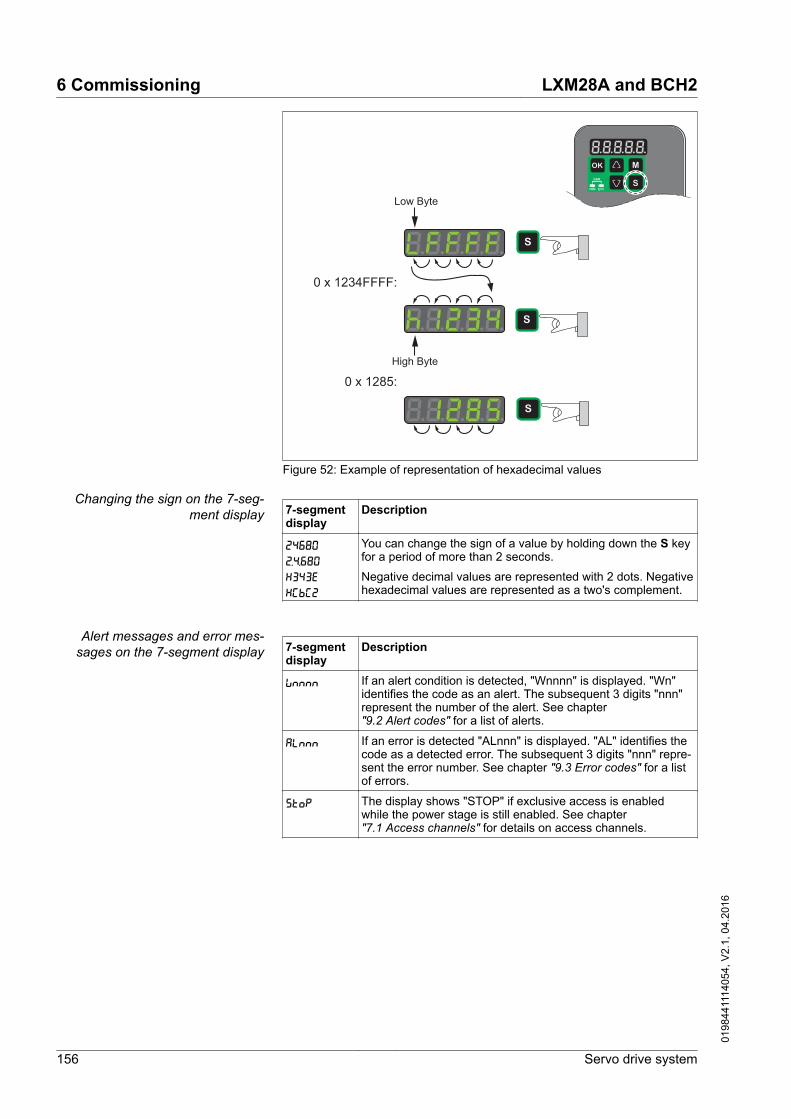
0 x 1234FFFF:
Low Byte
High Byte
0 x 1285:
Figure 52: Example of representation of hexadecimal values
Changing the sign on the 7-seg-ment display 7-segment
displayDescription
24680 2.4.680 x343E xCbC2
You can change the sign of a value by holding down the S keyfor a period of more than 2 seconds.
Negative decimal values are represented with 2 dots. Negativehexadecimal values are represented as a two's complement.
Alert messages and error mes-sages on the 7-segment display 7-segment
displayDescription
Wnnnn If an alert condition is detected, "Wnnnn" is displayed. "Wn"identifies the code as an alert. The subsequent 3 digits "nnn"represent the number of the alert. See chapter"9.2 Alert codes" for a list of alerts.
ALnnn If an error is detected "ALnnn" is displayed. "AL" identifies thecode as a detected error. The subsequent 3 digits "nnn" repre-sent the error number. See chapter "9.3 Error codes" for a listof errors.
STOP The display shows "STOP" if exclusive access is enabledwhile the power stage is still enabled. See chapter"7.1 Access channels" for details on access channels.
6 Commissioning LXM28A and BCH2
156 Servo drive system
0198
4411
1405
4, V
2.1,
04.
2016

6.2.3 Status information via the HMI
After you have powered on the drive, status information is displayedvia the HMI. Use the parameter P0-02 to select the type of statusinformation to be displayed. For example, if you set the parameterP0-02 to the value 7, the speed of rotation of the motor after is dis-played after you have powered on the drive.
LXM28A and BCH2 6 Commissioning
Servo drive system 157
0198
4411
1405
4, V
2.1,
04.
2016

SettingP0-02
Description
0 Actual position (with gear ratio applied) in the unit PUU
1 Target position (with gear ratio applied) in the unit PUU
2 Deviation between actual position and target position (withgear ratio applied) in the unit PUU
3 Actual position in motor increments (1280000 pulses/revolu-tion)
4 Target position in motor increments (1280000 pulses/revolu-tion)
5 Deviation between actual position and target position in motorincrements (1280000 pulses/revolution)
6 Reference value in kilopulses per second (kpps)
7 Actual velocity in min-1
8 Voltage for target velocity in V
9 Target velocity in min-1
10 Voltage for target torque in V
11 Target torque in percent of continuous motor current
12 Available current overhead used in percent of continuousmotor current
13 Peak current overhead consumed since the last power cycle ofthe drive in percent of continuous motor current (maximumvalue of occurring in setting 12 since last power cycle)
14 Mains voltage in V
15 Ratio of load inertia and motor inertia (divided by 10)
16 Power stage temperature in degrees Celsius (°C)
17 Resonance frequency in Hz
18 Absolute pulse number relative to encoder
19 Mapping parameter 1: Content of parameter P0-25 (mappingtarget is specified via parameter P0-35)
20 Mapping parameter 2: Content of parameter P0-26 (mappingtarget is specified via parameter P0-36)
21 Mapping parameter 3: Content of parameter P0-27 (mappingtarget is specified via parameter P0-37)
22 Mapping parameter 4: Content of parameter P0-28 (mappingtarget is specified via parameter P0-38)
23 Status indication 1: Content of parameter P0-09 (the statusinformation to be displayed is specified by parameter P0-17)
24 Status indication 2: Content of parameter P0-10 (the statusinformation to be displayed is specified by parameter P0-18)
25 Status indication 3: Content of parameter P0-11 (the statusinformation to be displayed is specified by parameter P0-19)
26 Status indication 4: Content of parameter P0-12 (the statusinformation to be displayed is specified by parameter P0-20)
6 Commissioning LXM28A and BCH2
158 Servo drive system
0198
4411
1405
4, V
2.1,
04.
2016

SettingP0-02
Description
27 Reserved
39 Status of digital inputs (content of P4-07)
40 Status of digital outputs (content of P4-09)
41 Drive status (content of P0-46)
42 Operating mode (content of P1-01)
49 Actual position encoder (content of P5-18)
50 Target velocity in min-1
53 Target torque in 0.1 percent of the nominal torque
54 Actual torque in 0.1 percent of the nominal torque
55 Actual torque in 0.01 A
77 Target velocity in min-1 in operating modes PT and PS
96 Firmware version and firmware revision of drive (P0-00 andP5-00)
111 Number of detected error
LXM28A and BCH2 6 Commissioning
Servo drive system 159
0198
4411
1405
4, V
2.1,
04.
2016

6.3 Setting the device address, baud rate and connection settings
Each device is identified by a unique address. Each device must haveits own unique node address, which may only be assigned once in thenetwork. The transmission rate (baud rate) must be the same for alldevices in the network.
Use the parameter P3-00 to set the Modbus device address.
Use the parameter P3-05 to set the CANopen device address.
Use the parameter P3-01 to set the baud rate.
Use the parameter P3-02 to set the connection settings.
-
CANopenAC
115200 Baud
57600 Baud
38400 Baud
19200 Baud
9600 Baud
125 kBit/s
1 MBit/s
-
500 kBit/s
250 kBit/s
Modbus
Figure 53: Setting the baud rate
6 Commissioning LXM28A and BCH2
160 Servo drive system
0198
4411
1405
4, V
2.1,
04.
2016

AModbus
Databits 8, Parity None, Stopbits 2
Databits 8, Parity None, Stopbits 1
Databits 8, Parity Odd, Stopbits 1
Databits 8, Parity Even, Stopbits 1
Figure 54: Modbus Connection Settings
WARNINGUNINTENDED EQUIPMENT OPERATION
• Verify that there is only one master controller configured on thenetwork or remote link.
• Verify that all devices have unique addresses.• Confirm that the device address is unique before placing the sys-
tem into service.
Failure to follow these instructions can result in death, seriousinjury, or equipment damage.
LXM28A and BCH2 6 Commissioning
Servo drive system 161
0198
4411
1405
4, V
2.1,
04.
2016

Parameter name Description UnitMinimum valueFactory settingMaximum valueHMI Format
Data typeR/WPersistent
Parameteraddress via field-bus
P3-00ADR
Device Address Modbus
Applicable operating mode: PT, PS, V, T
The device address must be unique.
Changed settings become active the nexttime the product is powered on.
-1127247Decimal
u16RWper.
Modbus 400h CANopen 4300h
P3-01BRT
Transmission Rate
Applicable operating mode: PT, PS, V, T
This parameter is used to set the data trans-mission rate.
For details see chapter"6.3 Setting the device address, baud rateand connection settings".
If this parameter is set via CANopen, onlythe CANopen transmission rate can be set.
Changed settings become active the nexttime the product is powered on.
-0h 102h 405h Hexadecimal
u16RWper.
Modbus 402h CANopen 4301h
P3-02PTL
Modbus Connection Settings
Applicable operating mode: PT, PS, V, T
This parameter specifies the Modbus con-nection settings.
For details see chapter"6.3 Setting the device address, baud rateand connection settings".
Changed settings become active the nexttime the product is powered on.
-6h 7h 9h Hexadecimal
u16RWper.
Modbus 404h CANopen 4302h
P3-03FLT
Detected Modbus Communication Errors -Handling
Applicable operating mode: PT, PS, V, T
This parameter specifies the response ofthe drive to a detected communication error.
Value 0: Detected alert
Value 1: Detected error
-0h 0h 1h Hexadecimal
u16RWper.
Modbus 406h CANopen 4303h
P3-04CWD
Modbus Connection Monitoring
Applicable operating mode: PT, PS, V, T
This parameter specifies the maximum per-missible duration for communication time-out. When this time has elapsed, the com-munication timeout is treated as a detectederror.
Setting this parameter to 0 to disables con-nection monitoring.
ms0020000Decimal
u16RWper.
Modbus 408h CANopen 4304h
6 Commissioning LXM28A and BCH2
162 Servo drive system
0198
4411
1405
4, V
2.1,
04.
2016

Parameter name Description UnitMinimum valueFactory settingMaximum valueHMI Format
Data typeR/WPersistent
Parameteraddress via field-bus
P3-05CMM
Device Address CANopen
Applicable operating mode: PT, PS, V, T
This parameter specifies the CANopenaddress of the drive in decimal format.
The device address must be unique.
Changes to this parameter becomes effec-tive only after a restart of the drive.
Changed settings become active the nexttime the product is powered on.
-00127Decimal
u16RWper.
Modbus 40Ah CANopen 4305h
P3-07CDT
Modbus Response Delay Time
Applicable operating mode: PT, PS, V, T
This parameter specifies the time delay withwhich the drive responds to the Modbusmaster.
0.5ms001000Decimal
u16RWper.
Modbus 40Eh CANopen 4307h
6.4 Commissioning software
The commissioning software LXM28 DTM Library has a graphic userinterface and is used for commissioning, diagnostics and testing set-tings.
Online help The commissioning software offers help functions, which can beaccessed via "? Help Topics" or by pressing the F1 key.
Source of commissioning software The latest version of the commissioning software LXM28 DTM Libraryis available for download from the Internet.
http://www.schneider-electric.com
LXM28A and BCH2 6 Commissioning
Servo drive system 163
0198
4411
1405
4, V
2.1,
04.
2016

6.5 Commissioning procedure
6.5.1 Verifying the direction of movement
WARNINGUNINTENDED MOVEMENT CAUSED BY INTERCHANGED MOTOR PHA-SES
Do not interchange the motor phases.
Failure to follow these instructions can result in death, seriousinjury, or equipment damage.
If your application requires an inversion of the direction of movement,you may parameterize the direction of movement.
Direction of movement Movements are made in positive or in negative directions.Definition of the direction of movement: Positive positive direction ofmovement is when the motor shaft rotates counterclockwise as youlook at the end of the protruding motor shaft.
-+Figure 55: Direction of movement with factory settings
Verifying the direction of move-ment
▶ Start the operating mode Jog. (HMI: P4-05)◁ The HMI displays the velocity in the unit min-1 for the operating
mode JOG.▶ Set a velocity suitable for your application and conform with the OK
key.◁ The HMI displays J0G.
Movement in positive direction:
▶ Press the "Up Arrow" key.◁ A movement is made in positive direction.
Movement in negative direction:
▶ Press the "Down Arrow" key.◁ A movement is made in negative direction.
Press the M key to terminate the operating mode Jog.
6 Commissioning LXM28A and BCH2
164 Servo drive system
0198
4411
1405
4, V
2.1,
04.
2016

Changing the direction of move-ment
If the expected direction of movement and the actual direction ofmovement are not identical, you can invert the direction of movement.
• Inversion of direction of movement is not activated:Movements are made in positive direction with positive target val-ues.
• Inversion of direction of movement is activated:Movements are made in positive direction with negative target val-ues.
The parameter P1-01 C = 1 allows you to invert the direction ofmovement.
A
B
C
D
not used
P1-01
1
0
Figure 56: Changing the direction of movement
LXM28A and BCH2 6 Commissioning
Servo drive system 165
0198
4411
1405
4, V
2.1,
04.
2016

6.5.2 Test operation in operating mode Velocity (V)
▶ Select the operating mode Velocity (V) via the parameter P1-01: =2. See See chapter "7.3.1 Setting the operating mode".
Set the parameter P1-01 to D=1. This assigns suitable defaults tothe signal input functions for the operating mode Velocity (V) sothat you only have to set DI6 to DI8.
New settings for the parameter P1-01 do not become active untilthe drive is powered on the next time.
▶ Restart the drive.▶ Select the following signal input functions via the parameters P2-10
to P2-17:
Digital input Parameter Setting Signal Function PIN at CN1DI1 P2-10 101 SON Enable power stage 9
DI2 P2-11 109 TRQLM Activate Torque Limitation 10
DI3 P2-12 114 SPD0 Velocity Reference Value Bit 0 34
DI4 P2-13 115 SPD1 Velocity Reference Value Bit 1 8
DI5 P2-14 102 FAULT_RESET Fault Reset 33
DI6 P2-15 0 - - -
DI7 P2-16 0 - - -
DI8 P2-17 0 - - -
See chapter "7.4.2 Parameterization of the signal input functions" foradditional information on the settings.
Error messages HMI
Message Cause RemedyAL013 Parameter P2-17 not set to 0 (deactivated). Set the parameter P2-17 to 0.
AL014 Parameter P2-15 not set to 0 (deactivated). Set the parameter P2-15 to 0.
AL015 Parameter P2-16 not set to 0 (deactivated). Set the parameter P2-16 to 0.
See chapter "9 Diagnostics and troubleshooting" for additional infor-mation on error messages.
Target velocity The target velocity is selected via the signal input functions SPD0(LSB) and SPD1 (MSB) (bit-coded):
- Signal state of the digitalsignal inputs
Target velocity via: Range
SPD1 SPD0S1 0 0 External analog sig-
nalVoltage between V_REF(pin 42) and GND (pin 44)
-10V ... 10V
S2 0 1 Internal parameters P1-09 -60000 ... 60000 *0.1 min-1
S3 1 0 P1-10S4 1 1 P1-11
6 Commissioning LXM28A and BCH2
166 Servo drive system
0198
4411
1405
4, V
2.1,
04.
2016

▶ Enable the power stage via DI1 (SON).◁ If DI3 (SPD0) and DI4 (SPD1) are deactivated, the target velocity
is supplied via the analog input V_REF.▶ Activate DI3(SPD0).◁ The target velocity is supplied via the parameter P1-09. The fac-
tory setting for the target velocity is 1000 min-1.
LXM28A and BCH2 6 Commissioning
Servo drive system 167
0198
4411
1405
4, V
2.1,
04.
2016

6.5.3 Tuning the control loops
Autotuning and manual tuning move the motor in order to tune thecontrol loops. Incorrect parameters may cause unintended move-ments or the loss of monitoring functions.
WARNINGUNINTENDED MOVEMENT
• Only start the system if there are no persons or obstructions inthe zone of operation.
• Verify that the values for the parameters P9-26 and P9-27 donot exceed the available movement range.
• Verify that the parameterized movement ranges are available.• In determining the available movement range, consider the addi-
tional distance for the deceleration ramp in the case of an EMER-GENCY STOP.
• Verify that the parameter settings for a Quick Stop are correct.• Verify correct operation of the limit switches.• Verify that a functioning emergency stop push-button is within
reach of all persons involved in the operation.
Failure to follow these instructions can result in death, seriousinjury, or equipment damage.
Autotuning adapts the control performance of the drive to the mechan-ical system used and optimizes the control loop settings appropriately.External factors such as a load at the motor are considered. The con-trol loop settings can also be optimized by means of manual tuning.
Two autotuning methods and manual tuning are provided for controlloop optimization:
• Easy Tuning: This type of autotuning is performed without userintervention. For most applications, Easy Tuning yields good,highly dynamic results.
• Comfort Tuning: This type of autotuning is performed with userintervention. You can select optimization criteria and set parame-ters for movement, direction and velocity.
• Manual Tuning: This type of tuning allows you to perform testmovements and optimize the control loop settings using the Scopefunction.
6 Commissioning LXM28A and BCH2
168 Servo drive system
0198
4411
1405
4, V
2.1,
04.
2016

6.5.3.1 Easy TuningEasy Tuning is started via the HMI or the commissioning softwareLXM28 DTM Library.
Easy Tuning requires an available movement range of 5 revolutions.During Easy Tuning, movements of 2.5 revolutions are performed inpositive direction of movement and 2.5 revolutions in negative direc-tion of movement. If this movement range is not available, you mustuse Comfort Tuning. Comfort Tuning allows you to manually set themovement range and the direction of movement.
Easy Tuning can be used for a ratio of motor inertia to load inertia ofup to 1:50.
Performing Easy Tuning Set the parameter P2-32 to 1 to perform Easy Tuning.
Easy tuning
Figure 57: Performing Easy Tuning
After you have started Easy Tuning via P2-32, the display of the HMIshows the progress as a percentage from tn000 to tn100.
Press the M button of the HMI to cancel autotuning.
If autotuning completes successfully, the display of the HMI shows themessage done.Press the OK key of the HMI to save the control loop parameters. Thedisplay of the HMI briefly shows the message saved.Press the M key of the HMI to discard the autotuning results.
If autotuning does not complete successfully, the display of the HMIshows the message ERROR. The cause can be read with the parame-ter P9-30.
The parameter P9-37 provides additional information on the last eventthat occurred during autotuning.
LXM28A and BCH2 6 Commissioning
Servo drive system 169
0198
4411
1405
4, V
2.1,
04.
2016

6.5.3.2 Comfort TuningComfort Tuning allows you to select optimization criteria and set val-ues for the movement.
Optimization criteria for ComfortTuning
Comfort Tuning allows you to select an optimization criterion for auto-tuning. The following optimization criteria are available:
• Optimization of the control loop parameters for minimum settlingtime with vibration suppression
• Optimization of the control loop parameters for minimum overshootwith vibration suppression
• Optimization of the control loop parameters for minimum settlingtime without vibration suppression
• Optimization of the control loop parameters for minimum overshootwithout vibration suppression
The illustration below shows optimization for minimum overshoot andoptimization for minimum settling time.
t
v [min-1]
t
v [min-1]
P9-29
12
Figure 58: Optimization in terms of overshoot or settling time
(1) Optimization for minimum overshoot(2) Optimization for minimum settling time
Vibration suppression compensates resonance frequencies of themechanical system. The option Vibration Suppression is available forboth optimization criteria.
Parameters for the movement forComfort Tuning
The following settings must be made for Comfort Tuning:
• Direction of movement• Velocity• Acceleration and deceleration• Movement range• Smoothing
These values must be as close as possible to the values used in theactual application. If you enter implausible values, Comfort Tuning iscanceled.
6 Commissioning LXM28A and BCH2
170 Servo drive system
0198
4411
1405
4, V
2.1,
04.
2016

Setting the direction of movement Set the direction of movement via the parameter P9-20.
Parameter name Description UnitMinimum valueFactory settingMaximum valueHMI Format
Data typeR/WPersistent
Parameteraddress via field-bus
P9-20LTNCYCLE
Autotuning - Direction of Movement
Applicable operating mode: PT, PS, V
This parameter sets the direction of move-ment for autotuning.Value 0: Both directions of movementValue 2: One direction of movement
-003Decimal
s16RW-
Modbus A28h CANopen 4914h
Setting the velocity Set the velocity via the parameter P9-29.
The velocity must be between 10 ... 100 % of the nominal velocity nN.
Parameter name Description UnitMinimum valueFactory settingMaximum valueHMI Format
Data typeR/WPersistent
Parameteraddress via field-bus
P9-29LTNVCRUISE
Autotuning - Velocity
Applicable operating mode: PT, PS, V
Bits 0 ... 15: Velocity for positive direction ofmovementBits 16 ... 31: Velocity for negative directionof movement
0.1rpm|0.1rpm---Decimal
u32RW-
Modbus A3Ah CANopen 491Dh
Setting acceleration and decelera-tion
Set the acceleration and the deceleration with the P9-31 parameter.
The value for the acceleration and the value for the deceleration mustbe between tmin and tmax:
tmin =10090
JM + JloadMmax
20π tmax =10033
JM + JloadMN
20π
JM = Moment of inertia of the motor in kg cm2 Jload = Moment of inertia of the load in kg cm2 Mmax = Peak torque in NmMN = Nominal torque in Nm
Parameter name Description UnitMinimum valueFactory settingMaximum valueHMI Format
Data typeR/WPersistent
Parameteraddress via field-bus
P9-31PTACCDEC
Autotuning - Acceleration and Deceleration
Applicable operating mode: PT, PS, V
Bits 0 ... 15: Acceleration for AutotuningBits 16 ... 31: Deceleration for Autotuning
ms|ms6| 66000| 600065500| 65500Decimal
u32RW-
Modbus A3Eh CANopen 491Fh
LXM28A and BCH2 6 Commissioning
Servo drive system 171
0198
4411
1405
4, V
2.1,
04.
2016

Setting the movement range Set the movement range via the parameters P9-26 and P9-27.
The movement range must be sufficiently large to allow for a constantmovement at the set speed in addition to the acceleration phase andthe deceleration phase.
Parameter name Description UnitMinimum valueFactory settingMaximum valueHMI Format
Data typeR/WPersistent
Parameteraddress via field-bus
P9-26PTPOS
Autotuning - Movement Range in Direction1
Applicable operating mode: PS
This parameter specifies the movementrange for autotuning in direction of move-ment 1.
The sign of the value determines the direc-tion of movement:
Positive value: Positive direction of move-ment as set via parameter P1-01
Negative value: Negative direction of move-ment as set via parameter P1-01
See parameter P9-20 to select one directionof movement or both directions of move-ment for Comfort Tuning.
PUU-214748364702147483647Decimal
s32RW-
Modbus A34h CANopen 491Ah
P9-27PTNEG
Autotuning - Movement Range in Direction2
Applicable operating mode: PS
This parameter specifies the movementrange for autotuning in direction of move-ment 2.
The sign of the value determines the direc-tion of movement:
Positive value: Positive direction of move-ment as set via parameter P1-01
Negative value: Negative direction of move-ment as set via parameter P1-01
See parameter P9-20 for Comfort Tuning ina single or in both directions of movement.
See parameter P9-20 to select one directionof movement or both directions of move-ment for Comfort Tuning.
PUU-214748364702147483647Decimal
s32RW-
Modbus A36h CANopen 491Bh
Setting smoothing Comfort Tuning uses S-curve smoothing by default. The value forsmoothing via the S-curve is optimized during Comfort Tunings.
The parameter P9-23 allows you to change from automatic smoothingto manual smoothing.
The following options are available for manual smoothing:
• No smoothing• Smoothing via low-pass filter with a fixed value• Smoothing via S-curve with a fixed value
6 Commissioning LXM28A and BCH2
172 Servo drive system
0198
4411
1405
4, V
2.1,
04.
2016

Parameter name Description UnitMinimum valueFactory settingMaximum valueHMI Format
Data typeR/WPersistent
Parameteraddress via field-bus
P9-23LTNSTIFF
Defines which values will be used for theposition command filters.
Applicable operating mode: PT, PS, V
Value 0: Automatic smoothing via S-curveoptimization of the valueValue 1: Manual smoothing
-001Decimal
u16RW-
Modbus A2Eh CANopen 4917h
P8-34MOVESMOOTH-MODE
Smoothing Filter for Operating modes PTand PS - Type
Applicable operating mode: PT, PS
Value 0: No smoothingValue 1: LPF smoothingValue 2: S-curve smoothing
Setting can only be changed if power stageis disabled.
-022Decimal
u16RWper.
Modbus 944h CANopen 4822h
The illustration below shows the movement during Comfort Tuning ifsmoothing via the low-pass filter is used:
0 t
v
≈ 42π x P8-33
Figure 59: Comfort Tuning with smoothing via low-pass filter
Parameter name Description UnitMinimum valueFactory settingMaximum valueHMI Format
Data typeR/WPersistent
Parameteraddress via field-bus
P8-33MOVE-SMOOTHLPFHZ
Low Pass Filter Setting
Applicable operating mode: PT, PS
Hz150005000Decimal
u16RWper.
Modbus 942h CANopen 4821h
The illustration below shows the movement during Comfort Tuning ifsmoothing via an S-curve is used:
LXM28A and BCH2 6 Commissioning
Servo drive system 173
0198
4411
1405
4, V
2.1,
04.
2016

0 t
v
P8-32
Figure 60: Comfort Tuning with smoothing via S-curve
Parameter name Description UnitMinimum valueFactory settingMaximum valueHMI Format
Data typeR/WPersistent
Parameteraddress via field-bus
P8-32MOVESMOO-THAVG
S-Curve Setting
Applicable operating mode: PT, PS
Setting can only be changed if power stageis disabled.
0.01ms25150025600Decimal
u32RWper.
Modbus 940h CANopen 4820h
6 Commissioning LXM28A and BCH2
174 Servo drive system
0198
4411
1405
4, V
2.1,
04.
2016

Performing Comfort Tuning Start Comfort Tuning by selecting the required method via the param-eter P2-32.
Parameter name Description UnitMinimum valueFactory settingMaximum valueHMI Format
Data typeR/WPersistent
Parameteraddress via field-bus
P2-32ATMODE
Autotuning
Applicable operating mode: PT, PS, V
This parameter is used to start autotuningwith the selected autotuning method.
Value 0: Stop AutotuningValue 1: Easy TuningValue 2: Comfort Tuning [minimum settlingtime, vibration suppression]Value 3: Comfort Tuning [minimum over-shoot, vibration suppression] Value 52: Comfort Tuning [minimum settlingtime, no vibration suppression] Value 53: Comfort Tuning [minimum over-shoot, no vibration suppression]
-0056Decimal
u16RW-
Modbus 340h CANopen 4220h
If you want Comfort Tuning in both directions, set parameter P9-20 to0. Then set the parameters P9-26 and P9-27 to the same values, butwith different signs (for example, P9-26 = -20000 and P9-27 =+20000). The value determines the movement range in both direc-tions.
If you want Comfort Tuning in a single direction, set parameter P9-20to 2. Then set the parameters P9-26 and P9-27 to the same values.The sign of the value determines the direction for Comfort Tuning. Forexample, if you set P9-26 = -20000 and P9-27 = -20000, Comfort Tun-ing is performed in negative direction of movement with a movementrange of 20000 PUU.
NOTE: If you do not enter consistent values for parameters P9-26 andP9-27, the autotuning is unsuccessful. Parameter P9-30 contains theinformation on the unsuccessful autotuning attempt.
After you have started the required Comfort Tuning method via P2-32,the display of the HMI shows the progress as a percentage fromtn000 to tn100.
Press the M button of the HMI to cancel autotuning.
If autotuning completes successfully, the display of the HMI shows themessage done.Press the OK key of the HMI to save the control loop parameters. Thedisplay of the HMI briefly shows the message saved.Press the M key of the HMI to discard the autotuning results.
If autotuning does not complete successfully, the display of the HMIshows the message ERROR. The cause can be read with the parame-ter P9-30.
The parameter P9-37 provides additional information on the last eventthat occurred during autotuning.
LXM28A and BCH2 6 Commissioning
Servo drive system 175
0198
4411
1405
4, V
2.1,
04.
2016

6.5.3.3 Manual tuningManual tuning is performed in the operating mode Internal Profile.Manual tuning allows you to perform test movements and optimize thecontrol loop settings using the Scope function.
NOTE: Manual tuning should only be attempted by trained personswho are familiar with and understand the contents of this manual andall other pertinent product documentation. These persons must havesufficient technical training, knowledge and experience and be able toforesee and detect potential hazards and issues that may be causedby manual tuning, by changing the settings and by the mechanical,electrical and electronic equipment of the entire system in which theproduct is used. No responsibility is assumed by Schneider Electric forany consequences arising out of the use of manual tuning.
Procedure for manual tuning The control loop parameters are tuned in the following sequence:
(1) Derivative gain, parameter P8-00 (KNLD)(2) Low-pass filter, parameters P8-14 (NLFILTDAMPING) and
P8-15 (NLFILTT1)(3) Re-tuning of the derivative gain, parameter P8-00 (KNLD)(4) Proportional gain, parameter P8-03 (KNLP)(5) Derivative-integral gain, parameter P8-02 (KNLIV)(6) Integral gain, parameter P8-01 (KNLI)(7) Compensation of the flexibility of the mechanical system,
parameters P8-05 (NLAFFLPFHZ) and P8-20 (NLPEAFF)
Depending on the requirements concerning the control performance,steps 2 and 3 can be omitted. Perform a movement in both directionsafter each of the steps below to check the recorded parameter valueson the Scope tab of the commissioning software LXM28 DTM Library.
6 Commissioning LXM28A and BCH2
176 Servo drive system
0198
4411
1405
4, V
2.1,
04.
2016

Step 1: Setting the derivative gain The objective of tuning the derivative gain is to achieve a current rip-ple that is as low as possible. The optimum value primarily dependson the load. Criteria for a well-tuned derivative gain include:
• For loads less than twice the rotor inertia: 5 % of the nominal cur-rent may be acceptable
• For higher loads: 10 % of the nominal current may be acceptable
The derivative gain is set via parameter P8-00 (KNLD). Procedure:
• Set the value of parameter P8-03 (KNLP) to 150 (corresponds to15 Hz).
• Set the value of parameter P8-01 (KNLI) to 0.• Set the value of parameter P8-02 (KNLIV) to 0.
LXM28A and BCH2 6 Commissioning
Servo drive system 177
0198
4411
1405
4, V
2.1,
04.
2016

• Progressively increase the value of parameter P8-00 (KNLD) untilthe oscilloscope shows oscillation of the reference current, P11-11(TCMD).
0
0
1000
2000
-2000
-1000
100 200 300 400
PTPVCMD
PE_PUU
ICMD
[ms]
Figure 61: Example P8-00 (KNLD) set to 1340 (134 Hz)
0
0
1000
2000
-2000
-1000
100 200 300 400
PTPVCMD
PE_PUU
ICMD
[ms]
Figure 62: Example P8-00 (KNLD) set too high at 2000 (200 Hz)
0
0
1000
2000
-2000
-1000
100 200 300 400
PTPVCMD
PE_PUU
ICMD
[ms]
Figure 63: Example P8-00 (KNLD) OK at 1500 (150 Hz)
6 Commissioning LXM28A and BCH2
178 Servo drive system
0198
4411
1405
4, V
2.1,
04.
2016

0
0100020003000
-3000-2000-1000
200 400 [ms]
-4000-5000
40005000
140012001000800600 18001600
PTPVCMD
PE_PUUICMD
Figure 64: Example P8-00 (KNLD) set too low at 100 (10 Hz)
NOTE: The process of tuning requires trials of successive approxima-tions. Values that are too high or too low relative to the other relevantvalues might cause instability. If it is necessary to have a low or highvalue of the parameter in the preceding example, you may need toadjust the values of the other relevant parameters to compensate andachieve a stable system.
LXM28A and BCH2 6 Commissioning
Servo drive system 179
0198
4411
1405
4, V
2.1,
04.
2016

Step 2: Setting the low-pass filter Setting the low-pass filter is an optional step in manual tuning of thecontrol loop parameters. The low-pass filter parameters are optimizedafter you have tuned the derivative gain. The objective of tuning thelow-pass filter parameters is to suppress high-frequency resonanceand reduce the response time of the control loops to a minimum.
The parameter P8-14 (NLFILTDAMPING) maintains the bandwidth ofthe low-pass filter up to the cutoff frequency. The parameter value isexpressed as a percentage. The parameter P8-15 (NLFILTT1) setsthe inverse frequency of the cutoff frequency. The parameter P8-14(NLFILTDAMPING) can also be used independently to allow for a cer-tain degree of compensation of system-related bandwidth limits.
Criteria for a well-tuned low-pass filter include:
• The value of parameter P8-14 (NLFILTDAMPING) is as high aspossible.
• The value of parameter P8-15 (NLFILTT1) is as low as possible.
The low-pass filter is set via parameters P8-14 (NLFILTDAMPING),and P8-15 (NLFILTT1). Procedure:
• Progressively increase the value of parameter P8-14 (NLFILT-DAMPING) until the oscilloscope shows noise and/or oscillation ofthe reference current, P11-11 (TCMD).
• Progressively decrease the value of parameter P8-15 (NLFILTT1)until the oscilloscope shows noise and/or oscillation of the refer-ence current P11-11 (TCMD).
6 Commissioning LXM28A and BCH2
180 Servo drive system
0198
4411
1405
4, V
2.1,
04.
2016

• Increase the value of parameter P8-15 (NLFILTT1) by 20 %, how-ever, by at least 0.05 ms.
0
0
1000
2000
-2000
-1000
100 200 300 400
PTPVCMD
PE_PUU
ICMD
[ms]
Figure 65: Example P8-14 (NLFILTDAMPING) OK (75 %)
0
0
1000
2000
-2000
-1000
100 200 300 400
PTPVCMD
PE_PUU
ICMD
[ms]
Figure 66: Example P8-15 (NLFILTT1) too low (0.5 ms)
0
0
1000
2000
-2000
-1000
100 200 300 400[ms]
PTPVCMD
PE_PUU
ICMD
Figure 67: Example P8-15 (NLFILTT1) OK (1.2 ms)
LXM28A and BCH2 6 Commissioning
Servo drive system 181
0198
4411
1405
4, V
2.1,
04.
2016

Step 3: Re-tuning of the derivativegain
If you have changed the low-pass filter values in parameters P8-14(NLFILTDAMPING), and P8-15 (NLFILTT1), the derivative gain canbe set to a higher value via parameter P8-00 (KNLD). Follow the pro-cedure described in step 1.
The objective of tuning the proportional gain is to get a constant andlow position deviation in the acceleration phase, the constant velocityphase and the deceleration phase and to have no oscillations duringthe transitions between these phases. In the oscilloscope, this is indi-cated by a shape that is as square and as flat as possible. Criteria fora well-tuned proportional gain include:
• No or minimum overshoot of position deviation• No or minimum current ripple• No or minimum oscillations at standstill
6 Commissioning LXM28A and BCH2
182 Servo drive system
0198
4411
1405
4, V
2.1,
04.
2016

Step 4: Setting the proportionalgain
The proportional gain is set via parameter P8-03 (KNLP). Procedure:
• Progressively increase the value of parameter P8-03 (KNLP) tofind the optimum value. The figures below show examples of theplot as the value approaches the optimum value.
0
0
1000
2000
-2000
-1000
100 200 300 400[ms]
PTPVCMD
PE_PUU
ICMD
Figure 68: Example P8-03 (KNLP) starting value (13 Hz)
0
0
1000
2000
-2000
-1000
100 200 300 400[ms]
PTPVCMD
PE_PUU
ICMD
Figure 69: Example P8-03 (KNLP) position deviation decreased (25 Hz)
0
0
1000
2000
-2000
-1000
100 200 300 400[ms]
PTPVCMD
PE_PUU
ICMD
Figure 70: Example P8-03 (KNLP) position deviation further decreased(35 Hz)
LXM28A and BCH2 6 Commissioning
Servo drive system 183
0198
4411
1405
4, V
2.1,
04.
2016

0
0
1000
2000
-2000
-1000
100 200 300 400[ms]
PTPVCMD
PE_PUU
ICMD
Figure 71: Example P8-03 (KNLP) position deviation further decreased(45 Hz)
0
0
1000
2000
-2000
-1000
100 200 300 400[ms]
PTPVCMD
PE_PUU
ICMD
Figure 72: Example P8-03 (KNLP) value too high - oscillation at standstill(65 Hz)
0
0
1000
2000
-2000
-1000
100 200 300 400[ms]
PTPVCMD
PE_PUU
ICMD
Figure 73: Example P8-03 (KNLP) value too high - oscillation at standstill(75 Hz)
6 Commissioning LXM28A and BCH2
184 Servo drive system
0198
4411
1405
4, V
2.1,
04.
2016

0
0
100
200
-200
-100
100 200 300 400[ms]
PTPVCMD
PE_PUU
ICMD
Figure 74: Example P8-03 (KNLP) value too high - oscillation at standstill,overshoot of position deviation (100 Hz)
0
0
100
200
300
-300
-200
-100
100 200 300 400[ms]
PTPVCMD
PE_PUU
ICMD
Figure 75: Example P8-03 (KNLP) OK (65 Hz)
LXM28A and BCH2 6 Commissioning
Servo drive system 185
0198
4411
1405
4, V
2.1,
04.
2016

Step 5: Setting the derivative-inte-gral gain
The objective of tuning the derivative-integral gain is to reduce theposition deviation. As a general rule, the value for the derivative-inte-gral gain (P8-02KNLIV) is within the following range:
P8-03 (KNLP) / 2 < P8-02 (KNLIV) < 2 x P8-03 (KNLP)
Progressively increasing the value of the derivative-integral gain pro-gressively decreases the position deviation during the accelerationphase, the constant velocity phase and the deceleration phase.
Criteria for a well-tuned derivative-integral gain include:
• Position deviation decreases rapidly after each transition of themovement phases (jerk)
• No or minimum overshoot of position deviation• No or minimum oscillations during transitions between the move-
ment phases
6 Commissioning LXM28A and BCH2
186 Servo drive system
0198
4411
1405
4, V
2.1,
04.
2016

• Oscillations at standstill as low as possible (+/- 1 encoder incre-ment)
The derivative-integral gain is set via parameter P8-02 (KNLIV). Pro-cedure:
• Progressively increase the value of parameter P8-02 (KNLIV) tofind the optimum value. The figures below show examples of theplot as the value approaches the optimum value.
0
0
10
20
30
-30
-20
-10
100 200 300 400[ms]
PTPVCMD
PE_PUU
ICMD
Figure 76: Example P8-02 (KNLIV) starting value (30 Hz)
0
0
10
20
30
-30
-20
-10
100 200 300 400[ms]
PTPVCMD
PE_PUU
ICMD
Figure 77: Example P8-02 (KNLIV) position deviation decreased (60 Hz)
0
0
10
20
30
-30
-20
-10
100 200 300 400[ms]
PTPVCMD
PE_PUU
ICMD
Figure 78: Example P8-02 (KNLIV) position deviation decreases rapidly whentarget velocity is reached (90 Hz)
LXM28A and BCH2 6 Commissioning
Servo drive system 187
0198
4411
1405
4, V
2.1,
04.
2016

0
0
10
20
-30
-20
-10
100 200 300 400[ms]
PTPVCMD
PE_PUU
ICMD
Figure 79: Example P8-02 (KNLIV) value too high - oscillation at standstill,overshoot of position deviation (120 Hz)
0
0
10
20
30
-30
-20
-10
100 200 300 400[ms]
PTPVCMD
PE_PUU
ICMD
Figure 80: Example P8-02 (KNLIV) OK (90 Hz)
Step 6: Setting the integral gain The objective of tuning the integral gain is to reduce the position devi-ation during movements and at standstill. Criteria for a well-tuned inte-gral gain include:
• Position deviation further reduced• No or minimum overshoot of position deviation at the end of the
deceleration phase• Oscillations at standstill as low as possible (+/- 1 encoder incre-
ment)
The integral gain is set via parameter P8-01 (KNLI). Procedure:
• Progressively increase the value of parameter P8-01 (KNLI) untilthe oscilloscope shows overshoot or oscillations. The figures belowshow examples of the plot as the value approaches the optimumvalue.
6 Commissioning LXM28A and BCH2
188 Servo drive system
0198
4411
1405
4, V
2.1,
04.
2016

0
0
10
20
30
-30
-20
-10
100 200 300 400[ms]
PTPVCMD
PE_PUU
ICMD
Figure 81: Example P8-01 (KNLI) value too high - oscillation at standstill,overshoot of position deviation (50 Hz)
0
0
10
20
30
-30
-20
-10
100 200 300 400[ms]
PTPVCMD
PE_PUU
ICMD
Figure 82: Example P8-01 (KNLI) OK (25 Hz)
Step 7: Compensation of the flexi-bility of the mechanical system
The parameters for compensation of the system flexibility reduce thevibrations caused by abrupt changes in the acceleration (jerk). Theparameters can also be used to further minimize overshoot or settlingtime.
The value of parameter P8-20 (NLPEAFF) reflects the oscillation fre-quency of the mechanical system, i.e. the coupling between the motorand the load. The coupling can be very rigid (for example, a directdrive or a low-backlash coupling) and less rigid (for example, a beltdrive or an elastic coupling). Systems with a high rigidity require ahigh value. Systems with high load inertia and less rigid couplingsrequire lower values. The less rigid the coupling, the lower this fre-quency. Depending on the application, the typical value range is 400… 30 Hz.
The parameter P8-05 (NLAFFLPFHZ) sets a low-pass filter for theacceleration profile. If the target value has a relatively low resolutionas, for example, in the case of a pulse train input, the calculatedacceleration may be subject to noise. The low-pass filter set via thisparameter can be used to smooth the acceleration profile. The param-eter can be used if the flexibility compensation set via parameterP8-20 (NLPEAFF) results in noise.
The compensation of the flexibility of the mechanical system is set viaparameters P8-05 (NLAFFLPFHZ) and P8-20 (NLPEAFF). Proce-dure:
LXM28A and BCH2 6 Commissioning
Servo drive system 189
0198
4411
1405
4, V
2.1,
04.
2016

• Set the value of parameter P8-05 (NLAFFLPFHZ) to a value threetimes as high as that of parameter P8-20 (NLPEAFF). With thisvalue, the bandwidth of this low-pass filter is sufficiently higher thanthe response time of the system.
• Progressively decrease the value of parameter P8-20 (NLPEAFF)to find the optimum value. The optimum value depends on youroptimization criterion: either short settling time or low position devi-ation.
Start with a high frequency of 400 Hz. Decrease the value andcompare the amplitudes for the position deviation and the settlingtime. Select the most suitable value according to your optimizationcriterion. The figures below show examples of the plot as the valueapproaches the optimum value.
0
0
10
20
30
-30
-20
-10
50 100 150[ms]
PTPVCMD
PE_PUU
ICMD
Figure 83: Example P8-20 (NLPEAFF) without compensation of the flexibility(5000 Hz)
0
0
10
20
30
-30
-20
-10
50 100 150[ms]
PTPVCMD
PE_PUU
ICMD
Figure 84: Example P8-20 (NLPEAFF) maximum position deviationdecreased (300 Hz)
6 Commissioning LXM28A and BCH2
190 Servo drive system
0198
4411
1405
4, V
2.1,
04.
2016

0
0
10
20
30
-30
-20
-10
50 100 150[ms]
PTPVCMD
PE_PUU
ICMD
Figure 85: Example P8-20 (NLPEAFF) maximum position deviation furtherdecreased (220 Hz)
0
0
10
20
30
-30
-20
-10
50 100 150[ms]
PTPVCMD
PE_PUU
ICMD
Figure 86: Example P8-20 (NLPEAFF) minimum position deviation, short set-tling time, oscillation at standstill (120 Hz)
0
0
10
20
30
-30
-20
-10
50 100 150[ms]
PTPVCMD
PE_PUU
ICMD
Figure 87: Example P8-20 (NLPEAFF) negative position deviation duringacceleration phase (100 Hz)
LXM28A and BCH2 6 Commissioning
Servo drive system 191
0198
4411
1405
4, V
2.1,
04.
2016

6.5.4 Verifying the safety function STO
The safety function STO must be tested at least once per year. Proce-dure:
▶ Operate the system with the nominal voltage at the STO inputs(see chapter "2.3.1.5 Signals").
▶ Enable the power stage (operating state 6 Operation Enabled).▶ Trigger the safety function STO by switching off the voltage (for
example, via an EMERGENCY STOP pushbutton).◁ The power stage is disabled and the error message AL501 is dis-
played.▶ Verify that drive is in the operating state Fault.▶ Check whether the drive can be set to the operating state Opera-
tion Enabled.◁ The drive remains in the operating state Fault.▶ Restore the STO voltage at the signal inputs of the safety function
STO and trigger a Fault Reset.▶ Verify that the drive can be set to the operating state Operation
Enabled.◁ The drive is set to the operating state Operation Enabled. Move-
ments are possible again.
6 Commissioning LXM28A and BCH2
192 Servo drive system
0198
4411
1405
4, V
2.1,
04.
2016
7 Operation
Unsuitable settings or unsuitable data may trigger unintended move-ments, trigger signals, damage parts and disable monitoring functions.Some settings do not become active until after a restart.
WARNINGUNINTENDED EQUIPMENT OPERATION
• Only start the system if there are no persons or obstructions inthe zone of operation.
• Do not operate the drive system with unknown settings or data.• Never modify a parameter unless you fully understand the param-
eter and all effects of the modification.• After modifications to settings, restart the drive and verify the
saved data or settings.• When commissioning the product, carefully run tests for all oper-
ating states and potential error situations.• Verify the functions after replacing the product and also after
making modifications to the settings or data.
Failure to follow these instructions can result in death, seriousinjury, or equipment damage.
LXM28A and BCH2 7 Operation
Servo drive system 193
0198
4411
1405
4, V
2.1,
04.
2016

7.1 Access channels
The product can be accessed via different types of access channels.Simultaneous access via multiple access channels or the use ofexclusive access may cause unintended equipment operation.
WARNINGUNINTENDED EQUIPMENT OPERATION
• Verify that simultaneous access via multiple access channelscannot cause unintended triggering or blocking of commands.
• Verify that the use of exclusive access cannot cause unintendedtriggering or blocking of commands.
• Verify that the required access channels are available.
Failure to follow these instructions can result in death, seriousinjury, or equipment damage.
The product can be addressed via different access channels. Accesschannels are:
• Integrated HMI• Fieldbus• Commissioning software LXM28 DTM Library• Digital and analog Input signals
If several access channels are active at the same time, this may leadto unintended equipment operation.
The product allows you to work with exclusive access which limitsaccess to the product via a single access channel.
Only one access channel can have exclusive access to the product.An exclusive access can be provided via different access channels:
• Via the integrated HMI:
The operating mode Jog or Autotuning can be started via the HMI.• Via a fieldbus:
Exclusive access is provided to a fieldbus by blocking the otheraccess channels with the parameter AccessLock.
• Via the commissioning software LXM28 DTM Library:
The commissioning software receives exclusive access via theswitch "Exclusive access" in position "On".
When the product is powered on, there is no exclusive access via anaccess channel.
The reference values are effective at the analog inputs and at thepulse inputs when the product is powered on. If exclusive access hasbeen assigned to an access channel, signals at the pulse inputs areignored.
The signal input functions "STO","HALT", "FAULT_RESET", "SON"(falling edge), "CWL(NL)" and "CCWL(PL)" are always effective duringexclusive access.
7 Operation LXM28A and BCH2
194 Servo drive system
0198
4411
1405
4, V
2.1,
04.
2016

7.2 Operating states
7.2.1 State diagram
When the product is powered on and when an operating mode is star-ted, the product goes through a number of operating states.
The state diagram (state machine) shows the relationships betweenthe operating states and the state transitions.
The operating states are internally monitored and influenced by moni-toring functions.
LXM28A and BCH2 7 Operation
Servo drive system 195
0198
4411
1405
4, V
2.1,
04.
2016

State diagram
3
4
5
Ready To Switch On
Switched On
Switch On Disabled
Not Ready To Switch On
1
2
Fault
Fault Reaction Active
8
9
Quick Stop ActiveOperation Enabled
RUN/HALT6 7
Start
Apply power to the drive
Operating state Error
Motor under current
Motor without current
Figure 88: State diagram
Operating statesOperating state Description1 Start Electronics are initialized
2 Not Ready To Switch On The power stage is not ready to switch on
3 Switch On Disabled Impossible to enable the power stage
4 Ready To Switch On The power stage is ready to switch on.
5 Switched On Power stage is switched on
6 Operation Enabled Power stage is enabledSelected operating mode is active
7 Quick Stop Active "Quick Stop" is being executed
8 Fault Reaction Active Error response is active
9 Fault Error response terminatedPower stage is disabled
Resetting an error message After you have removed the cause of the detected error, you can resetthe error message in one of the following ways:
• With a rising edge of the signal input function "FAULT_RESET"• With a rising edge of the signal input function "SON"• By setting parameter P0-01 to the value 0
7 Operation LXM28A and BCH2
196 Servo drive system
0198
4411
1405
4, V
2.1,
04.
2016

7.3 Operating modes
7.3.1 Setting the operating mode
PulseTrain (PT)
PositionSequence (PS)
Velocity (V)
Torque (T)
Pulse Train (PT)Velocity (V)
Pulse Train (PT)
Velocity (V)Torque (T)
CANopen
Torque (T)
Position Sequence (PS)Velocity (V)
Position Sequence (PS)Torque (T)
InternalVelocity (Vz)
InternalTorque (Tz)
Single Mode Dual Mode
A
C
Dnotused
notused
Figure 89: Setting the operating mode
There are 3 types of operating modes.
• Single Mode operating modes
- The drive operates in a single operating mode.• Dual Mode operating modes
- The drive operates using 2 operating modes alternately. Thesignal input functions are used to switch between the operatingmodes. See"7.4.2 Parameterization of the signal input functions".
• CANopen Mode operating mode
- The drive operates in the operating mode CANopen.
The operating modes Torque (T) and Torque (Tz) and the dual operat-ing modes with Torque (T) and Torque (Tz) do not provide decelera-tion functionality in response to a power stage disable request. Inthese operating modes, the motor coasts down to a standstill inresponse to a power stage disable request. You must install additional
LXM28A and BCH2 7 Operation
Servo drive system 197
0198
4411
1405
4, V
2.1,
04.
2016

equipment such as a dedicated service brake if your applicationrequires faster deceleration of the load.
WARNINGUNINTENDED EQUIPMENT OPERATION
• Verify that all loads come to a secure standstill when the powerstage is disabled in the operating modes Torque (T) and Torque(Tz) and in all dual-mode operating modes with Torque (T) andTorque (Tz) by performing comprehensive commissioning testsunder maximum load conditions.
• During commissioning, trigger all signals and simulate all condi-tions that cause a power stage disable request in order to verifythat all loads come to a secure standstill when the power stage isdisabled in the operating modes Torque (T) and Torque (Tz) andin all dual-mode operating modes with Torque (T) and Torque (Tz)under maximum load conditions.
• Install a dedicated service brake if coasting does not meet thedeceleration requirements of your application.
Failure to follow these instructions can result in death, seriousinjury, or equipment damage.
7 Operation LXM28A and BCH2
198 Servo drive system
0198
4411
1405
4, V
2.1,
04.
2016

7.3.2 Jog operation
Description In the Jog operation, a movement is made from the actual motor posi-tion in the specified direction.
The parameter P4-05 is used to set the velocity for the movement inthe unit min-1.
The movement can be performed via the arrow keys at the HMI or viathe signal input functions JOGP and JOGN.
See chapter "7.4.2 Parameterization of the signal input functions" foradditional information on the parameterizable signal input functions.
Jog via HMI If the HMI is used, the movements are performed via the arrow keys.The operating mode is terminated via the M key.
min-1
Figure 90: Starting a movement in the operating mode Jog
LXM28A and BCH2 7 Operation
Servo drive system 199
0198
4411
1405
4, V
2.1,
04.
2016

7.3.3 Operating mode Pulse Train (PT)
Description In the operating mode Pulse Train (PT), movements are carried outaccording to externally supplied reference value signals. A positionreference value is calculated on the basis of these external referencevalues plus an adjustable gear ratio. The reference value signals canbe A/B signals, P/D signals or CW/CCW signals.
Method A movement can be made using one of 3 methods:
• Position synchronization without compensation movement
In the case of position synchronization without compensationmovement, the movement is made synchronously (position syn-chronicity) with the supplied reference value signals. Referencevalue signals supplied during an interruption are not taken intoaccount.
• Position synchronization with compensation movement
In the case of position synchronization with compensation move-ment, the movement is made synchronously (position synchronic-ity) with the supplied reference value signals. Reference value sig-nals supplied during an interruption are taken into account andcompensated for.
• Velocity synchronization
In the case of velocity synchronization, the movement is made syn-chronously (velocity synchronicity) with the supplied referencevalue signals.
Parameter name Description UnitMinimum valueFactory settingMaximum valueHMI Format
Data typeR/WPersistent
Parameteraddress via field-bus
P8-31GEARING_MODE
Method for Operating Mode Pulse Train(PT)
Applicable operating mode: PT
Value 0: Synchronization deactivatedValue 1: Position synchronization withoutcompensation movementValue 2: Position synchronization with com-pensation movementValue 3: Velocity synchronization
The parameters for acceleration (P1-34),deceleration (P1-35) and velocity (P1-55)act as limitations for the sychonization.
-013Decimal
u16RWper.
Modbus 93Eh CANopen 481Fh
7 Operation LXM28A and BCH2
200 Servo drive system
0198
4411
1405
4, V
2.1,
04.
2016

7.3.3.1 Pulse SettingsThe parameter P1-00 lets you specify the type of reference value sig-nals, the input polarity, the maximum signal frequency and the sourceof the pulses.
Parameter name Description UnitMinimum valueFactory settingMaximum valueHMI Format
Data typeR/WPersistent
Parameteraddress via field-bus
P1-00PTT
Reference Value Signal - Pulse Settings
Applicable operating mode: PT
A
B
C
D
not used
This parameter is used to configure the ref-erence value signals for the operating modePT.
A: Type of reference value signals
B: Signal frequency
C: Input polarity
D: Source of reference value signals
Setting can only be changed if power stageis disabled.
-0h 2h 1132h Hexadecimal
u16RWper.
Modbus 200h CANopen 4100h
LXM28A and BCH2 7 Operation
Servo drive system 201
0198
4411
1405
4, V
2.1,
04.
2016

Settings A and C Type of reference value signals and input polarity
C = 0 Positive input polarity
C = 1 Negative input polarity
Positive direction ofmovement
Negative direction ofmovement
Positive direction ofmovement
Negative direction ofmovement
A = 0 A/B signals PULSE
SIGNSIGN
PULSE
A = 1 CW/CCW signals PULSE
SIGNSIGN
PULSE
A = 2 P/D signals
SIGN
PULSE PULSE
SIGN
Setting B Maximum signal frequency
Low-speed pulsesPULSE, SIGN
High-speed pulsesHPULSE, HSIGN
B = 0 500 Kpps 1) 4 Mpps
B = 1 200 Kpps 2 Mpps
B = 2 100 Kpps 1 Mpps
B = 3 50 Kpps 500 Kpps1) Only possible with RS422.
Parameter P2-65 bit 6 allows you to set an error response for fre-quencies exceeding the maximum signal frequency by more than10 %.
Setting D Source of the pulses
D = 0 Low-speed pulses CN1 Terminal: PULSE, SIGN
D = 1 High-speed pulses CN1 Terminal: HPULSE, HSIGN
The source of the pulses can also be set via the signal input functionPTCMS. The settings of the signal input function take priority over thesettings of the parameter P1-00.
7 Operation LXM28A and BCH2
202 Servo drive system
0198
4411
1405
4, V
2.1,
04.
2016

7.3.3.2 Gear ratioThe gear ratio is the ratio of the number of motor increments and thenumber of reference increments.
The reference increments are supplied as reference value signals viathe signal inputs.
Gear factor = =Reference increments
Motor increments Gear factor numerator
Gear factor denominator
Figure 91: Gear ratio
With the factory setting for the gear ratio, 100000 reference incre-ments correspond to one revolution.
There are 1280000 motor increments per revolution.
Parameterization You can set up 4 gear ratios. It is possible to switch between thesegear ratios via the signal inputs.
The gear ratios are set via parameters P1-44, P1-45, P2-60, P2-61,and P2-62.
You can switch between the gear ratios with the signal input functionsGNUM0 and GNUM1.
GNUM1
0 0
0 1
1 0
1 1
GNUM0 =
P1-44
P2-60
P2-61
P2-62
P1-45
P1-45
P1-45
P1-45
Figure 92: Gear ratio
In order to switch between the gear ratios via the signal inputs, youmust first parameterize the signal input functions GNUM0 andGNUM1, see chapter"7.4.2 Parameterization of the signal input functions".
Example 1 Calculation of number of motor revolutions corresponding to30000 PUU:
1280000M384000
384000 x = = 0,330000 PUU
P1-44 = 128
P1-45 = 10
Figure 93: Calculation example 1
Example 2 Calculation of gear ratio if 10000 PUU are to effect 500 revolutions ofthe motor shaft:
LXM28A and BCH2 7 Operation
Servo drive system 203
0198
4411
1405
4, V
2.1,
04.
2016

P1-44 = 128 x 500
P1-45 = 1
M500=10000 PUUP1-44 = ?
P1-45 = ?
500 x
x
=
10000
1280000
M1
1280000
M1
500 x
x 1
128
M
Figure 94: Calculation example 2
Example 3 A machine encoder with 1024 lines per revolution is to effect one revo-lution of the motor shaft with one revolution.
M1= x1024 ||||| 1| = 4 A/B
M1 M1
P1-44 = 1 280 000
P1-45 = 4096
4096
P1-00 (A LSB) = 0
A/B
PTI F
Figure 95: Calculation example 3
7 Operation LXM28A and BCH2
204 Servo drive system
0198
4411
1405
4, V
2.1,
04.
2016

7.3.3.3 Acceleration and deceleration limitationThe parameters P1-34 and P1-35 allow you to set a limitation for theacceleration and deceleration.
t
v
P1-34 P1-35
Figure 96: Acceleration and deceleration limitation
Parameter name Description UnitMinimum valueFactory settingMaximum valueHMI Format
Data typeR/WPersistent
Parameteraddress via field-bus
P1-34TACC
Acceleration Period
Applicable operating mode: PT, V
The acceleration period is the time in milli-seconds required to accelerate from motorstandstill to 6000 min-1.
For operating mode V, this parameter speci-fies the acceleration. If the target velocity issupplied as an analog signal, the maximumvalue of this parameter is automatically limi-ted to 20000.
For operating mode PT, this parameterspecifies an acceleration limitation for thepulses at the PTI interface.
ms63065500Decimal
u16RWper.
Modbus 244h CANopen 4122h
P1-35TDEC
Deceleration Period
Applicable operating mode: PT, V
The deceleration period is the time in milli-seconds required to decelerate from6000 min-1 to motor standstill.
For operating mode V, this parameter speci-fies the deceleration. If the target velocity issupplied as an analog signal, the maximumvalue of this parameter is automatically limi-ted to 20000.
For operating mode PT, this parameterspecifies a deceleration limitation for thepulses at the PTI interface.
ms63065500Decimal
u16RWper.
Modbus 246h CANopen 4123h
LXM28A and BCH2 7 Operation
Servo drive system 205
0198
4411
1405
4, V
2.1,
04.
2016

7.3.4 Operating mode Position Sequence (PS)
Description The operating mode Position Sequence (PS) allows you to set andexecute 32 motion profiles in any sequence. The motion profiles aredefined via 32 data sets.
The following values can be set for each data set:
• Target position• Type of movement: Absolute or relative• Type of transition between data sets• Acceleration• Target velocity• Deceleration• Waiting time after completion of the data set
In addition, a Homing data set is provided. This Homing data set isused to set a reference point for absolute movements.
Configuration The data sets are configured by means of the commissioning softwareLXM28 DTM Library.
Starting movements The data sets are selected via the signal input functionsPOS0 ... POS4. The table below shows the bit pattern used to selectthe data sets.
Data set POS4 POS3 POS2 POS1 POS01 0 0 0 0 0
2 0 0 0 0 1
3 0 0 0 1 0
4 0 0 0 1 1
5 0 0 1 0 0
... ... ... ... ... ...
31 1 1 1 1 0
32 1 1 1 1 1
The selected data set is executed and the movement started via thesignal input function CTRG, rising edge, or via the parameter P5-07.
See chapter "7.4 Setting the digital signal inputs and signal outputs"for additional information on parameterizing the signal input functions.
7 Operation LXM28A and BCH2
206 Servo drive system
0198
4411
1405
4, V
2.1,
04.
2016

Example The illustration below shows how the data sets are started and termi-nated via the signal input functions and the signal output functionsCMD_OK, TPOS and MC_OK:
32
2
11ms
--
POS0ON
ON
ON
ON
P2-09
ON
OFF OFF
OFF
OFF
OFF
OFF
OFF
OFFON
ONPOS2
CTRG
SON
POS1
CMD_OK
MC_OK
TPOS
Figure 97: Operating mode Position Sequence (PS)
See chapter "7.4 Setting the digital signal inputs and signal outputs"for additional information.
LXM28A and BCH2 7 Operation
Servo drive system 207
0198
4411
1405
4, V
2.1,
04.
2016

7.3.4.1 Structure of a data setTarget position The target position is set in the user-defined unit. With the factory
scaling, the resolution is 100000 user-defined units per revolution.
See chapter "7.3.4.2 Scaling" for additional information on scaling.
Type of movement In the case of a relative movement, the movement is relative with ref-erence to the previous target position or the current motor position.
500 700
In the case of an absolute movement, the movement is absolute withreference to the zero point.
1200
500
Homing or position setting is required before the first absolute move-ment can be performed.
Transition between data sets There are two types of transitions:
• The subsequent data set is only started after the preceding dataset has been completed.
• The subsequent data set is started as soon as it is triggered via thesignal input function CTRG or the parameter P5-07.
Acceleration Period The acceleration period is the time in milliseconds required to acceler-ate from motor standstill to 6000 min-1. It is used to set the accelera-tion ramp.
Target velocity The target velocity is reached after the time required for accelerationhas passed.
Deceleration Period The deceleration period is the time in milliseconds required to deceler-ate from 6000 min-1 to motor standstill. It is used to set the decelera-tion ramp.
Waiting time The waiting time is the period of time that must pass after the targetposition has been reached for the data set to be considered comple-ted.
7 Operation LXM28A and BCH2
208 Servo drive system
0198
4411
1405
4, V
2.1,
04.
2016

Parameters for the data sets The data set are configured via parameters P6-02 ... P6-65 andP7-02 ... P7-65. The table below provides an overview:
Data set Target posi-tion
Type / Transi-tion
Acceleration /deceleration
Waiting time /target veloc-ity
1 P6-02 P6-03 P7-02 P7-03
2 P6-04 P6-05 P7-04 P7-05
3 P6-06 P6-07 P7-06 P7-07
4 P6-08 P6-09 P7-08 P7-09
5 P6-10 P6-11 P7-10 P7-11
6 P6-12 P6-13 P7-12 P7-13
7 P6-14 P6-15 P7-14 P7-15
8 P6-16 P6-17 P7-16 P7-17
9 P6-18 P6-19 P7-18 P7-19
10 P6-20 P6-21 P7-20 P7-21
11 P6-22 P6-23 P7-22 P7-23
12 P6-24 P6-25 P7-24 P7-25
13 P6-26 P6-27 P7-26 P7-27
14 P6-28 P6-29 P7-28 P7-29
15 P6-30 P6-31 P7-30 P7-31
16 P6-32 P6-33 P7-32 P7-33
17 P6-34 P6-35 P7-34 P7-35
18 P6-36 P6-37 P7-36 P7-37
19 P6-38 P6-39 P7-38 P7-39
20 P6-40 P6-41 P7-40 P7-41
21 P6-42 P6-43 P7-42 P7-43
22 P6-44 P6-45 P7-44 P7-45
23 P6-46 P6-47 P7-46 P7-47
24 P6-48 P6-49 P7-48 P7-49
25 P6-50 P6-51 P7-50 P7-51
26 P6-52 P6-53 P7-52 P7-53
27 P6-54 P6-55 P7-54 P7-55
28 P6-56 P6-57 P7-56 P7-57
29 P6-58 P6-59 P7-58 P7-59
30 P6-60 P6-61 P7-60 P7-61
31 P6-62 P6-63 P7-62 P7-63
32 P6-64 P6-65 P7-64 P7-65
LXM28A and BCH2 7 Operation
Servo drive system 209
0198
4411
1405
4, V
2.1,
04.
2016

7.3.4.2 ScalingScaling is the ratio of the number of user-defined units and the num-ber of internal units.
The user-defined units are supplied as parameter values in the unitPUU.
Scaling factor = =User-defined units
Internal units Gear factor numerator
Gear factor denominator
Figure 98: Scaling factor
With the factory setting for the scaling factor, 100000 user-definedunits correspond to one revolution.
The internal units are 1280000 increments per revolution.
Parameterization The scaling factor is set using the parameters P1-44 and P1-45.
P1-44P1-45
Figure 99: Scaling factor
Example 1 Calculation of number of motor revolutions corresponding to30000 PUU:
1280000M384000
384000 x = = 0,330000 PUU
P1-44 = 128
P1-45 = 10
Figure 100: Calculation example 1
Example 2 Calculation of the scaling factor if 10000 PUU are to effect 500 revolu-tions of the motor shaft:
P1-44 = 128 x 500
P1-45 = 1
M500=10000 PUUP1-44 = ?
P1-45 = ?
500 x
x
=
10000
1280000
M1
1280000
M1
500 x
x 1
128
M
Figure 101: Calculation example 2
7 Operation LXM28A and BCH2
210 Servo drive system
0198
4411
1405
4, V
2.1,
04.
2016

7.3.4.3 Homing data set for absolute movementsThe Homing data set is used to establish a reference between amechanical position and the actual position of the motor.
A reference between a mechanical position and the actual position ofthe motor is generated by means of a reference movement or bymeans of position setting.
A successful reference movement, or position setting, homes themotor.
Homing establishes the zero point for absolute movements.
Methods The following methods are available:
• Reference movement to a limit switch
In the case of a reference movement to a limit switch, a movementto the negative limit switch or the positive limit switch is performed.When the limit switch is reached, the motor is stopped and a move-ment is made back to the switching point of the limit switch.From the switching point of the limit switch, an additional move-ment can be made to the next index pulse of the motor.The switching point of the limit switch or the position of the indexpulse point is the reference point.
• Reference movement to the reference switch
In the case of a reference movement to the reference switch, amovement to the reference switch is performed.When the reference switch is reached, the motor is stopped and amovement is made back to the switching point of the referenceswitch.From the switching point of the reference switch, an additionalmovement can be made to the next index pulse of the motor.The switching point of the reference switch or the position of theindex pulse point is the reference point.
• Reference movement to the index pulse
In the case of a reference movement to the index pulse, a move-ment is made from the actual position to the next index pulse. Theposition of the index pulse is the reference point.
• Position setting
In the case of position setting, the current motor position is set to adesired position value.
A reference movement must be terminated without interruption for thenew zero point to be valid. If the reference movement is interrupted, itmust be started again.
Starting the Homing data set The Homing data set can be started in the following ways:
• Automatic start when the power stage is enabled for the first timeThe automatic start can be set with the parameter P6-01.
• Start via the signal input function GOTOHOMEThe signal input function must have been parameterized, seechapter "7.4 Setting the digital signal inputs and signal outputs".
LXM28A and BCH2 7 Operation
Servo drive system 211
0198
4411
1405
4, V
2.1,
04.
2016

Setting automatic start and thesubsequent data set
The parameter P6-01 is used to set the automatic start and select adata set to be executed after completion of the Homing data set.The parameter P7-01 is used to set a waiting time for the subsequentdata set. The subsequent data set is started after the waiting time haselapsed.
Parameter name Description UnitMinimum valueFactory settingMaximum valueHMI Format
Data typeR/WPersistent
Parameteraddress via field-bus
P6-01ODEF
Subsequent Data Set and Auto-start ofHoming Data Set
Applicable operating mode: PS
Bit 0:0 = Do not start Homing after first powerstage enable1 = Start Homing after first power stageenable
Bits 1 ... 7: Reserved
Bits 8 ... 15: Subsequent data set
-0h 0h 2001h Hexadecimal
u32RWper.
Modbus 702h CANopen 4601h
P7-01HOME_DLY
Waiting Time of Homing Data Set
Applicable operating mode: PS
Bits 0 ... 15: Waiting time until next datasetis started
Bits 16 ... 31: Reserved
ms0032767Decimal
u32RWper.
Modbus 802h CANopen 4701h
Setting acceleration and decelera-tion
The acceleration and deceleration for the Homing data set are set viathe parameter P7-00.
Parameter name Description UnitMinimum valueFactory settingMaximum valueHMI Format
Data typeR/WPersistent
Parameteraddress via field-bus
P7-00HOME_ACC_DEC
Deceleration and Acceleration of HomingData Set
Applicable operating mode: PS
Bits 0 ... 15: Deceleration
Bits 16 ... 31: Acceleration
ms|ms6| 6200| 20065500| 65500Decimal
u32RWper.
Modbus 800h CANopen 4700h
7 Operation LXM28A and BCH2
212 Servo drive system
0198
4411
1405
4, V
2.1,
04.
2016

Setting velocities The parameters P5-05 and P5-06 are used to set the velocities forsearching the switch and for moving away from the switch.
Parameter name Description UnitMinimum valueFactory settingMaximum valueHMI Format
Data typeR/WPersistent
Parameteraddress via field-bus
P5-05HOMESPEED1
Homing - Fast Velocity for Reference Move-ment
Applicable operating mode: PS
0.1rpm10100060000Decimal
u32RWper.
Modbus 60Ah CANopen 4505h
P5-06HOMESPEED2
Homing - Slow Velocity for Reference Move-ment
Applicable operating mode: PS
0.1rpm1020060000Decimal
u32RWper.
Modbus 60Ch CANopen 4506h
Defining the zero point The parameter P6-00 is used to specify a position value, which is setat the reference point after a successful reference movement or afterposition setting. This position value defines the zero point.
Parameter name Description UnitMinimum valueFactory settingMaximum valueHMI Format
Data typeR/WPersistent
Parameteraddress via field-bus
P6-00ODAT
Position of Homing Data Set
Applicable operating mode: PS
After a successful reference movement, thisposition is automatically set at the referencepoint.
Bits 0 ... 31: Position
PUU-214748364702147483647Decimal
s32RWper.
Modbus 700h CANopen 4600h
LXM28A and BCH2 7 Operation
Servo drive system 213
0198
4411
1405
4, V
2.1,
04.
2016

Selecting the Homing method The parameter P5-04 is used to set the Homing method.
XYZReserved
Figure 102: Settings for the Homing method
Setting Z - limit switch Setting Y - index pulse Settings X - Homing method- Y=0: Movement back to the last
index pulse
Y=2: No movement to the indexpulse
0 Movement in positive direction to thepositive limit switch
- 1 Movement in negative direction to thenegative limit switch
Z=0: Stop after limit switch isreached and trigger alert AL014 orAL015
Z=1: Move in opposite directionafter having reached the limitswitch, no alert
Y=0: Movement back to the lastindex pulse
Y=1: Movement to the next indexpulse
Y=2: No movement to the indexpulse
2 Movement in positive direction to the ris-ing edge of the reference switch
3 Movement in negative direction to the ris-ing edge of the reference switch
- 4 Movement in positive direction to the nextindex pulse
- 5 Movement in negative direction to thenext index pulse
Y=0: Movement back to the lastindex pulse
Y=1: Movement to the next indexpulse
Y=2: No movement to the indexpulse
6 Movement in positive direction to the fall-ing edge of the reference switch
7 Movement in negative direction to thefalling edge of the reference switch
- - 8 Position setting
The illustrations below show the Homing methods.
7 Operation LXM28A and BCH2
214 Servo drive system
0198
4411
1405
4, V
2.1,
04.
2016

Reference movement to the posi-tive limit switch
The following illustrations show reference movements to the positivelimit switch from different starting positions.
M
NegativeLimit Switch
PositiveLimit Switch
�
�
�
�
�
�
ZYX = -00
�
�
Figure 103: Reference movement (ZYX = -00)
(1) Movement to rising edge at velocity P5-05(2) Movement to falling edge at velocity P5-05(3) Movement to the index pulse at velocity P5-06
M
NegativeLimit Switch
PositiveLimit Switch
�
�
�
�
�
ZYX = -20
Figure 104: Reference movement (ZYX = -20)
(1) Movement to rising edge at velocity P5-05(2) Movement to falling edge at velocity P5-06
LXM28A and BCH2 7 Operation
Servo drive system 215
0198
4411
1405
4, V
2.1,
04.
2016

Reference movement to the nega-tive limit switch
The following illustrations show reference movements to the negativelimit switch from different starting positions.
M
NegativeLimit Switch
PositiveLimit Switch
�
�
�
�
�
�
ZYX = -01
�
�
Figure 105: Reference movement (ZYX = -01)
(1) Movement to rising edge at velocity P5-05(2) Movement to falling edge at velocity P5-05(3) Movement to the index pulse at velocity P5-06
M
NegativeLimit Switch
PositiveLimit Switch
�
�
�
�
�
ZYX = -21
Figure 106: Reference movement (ZYX = -21)
(1) Movement to rising edge at velocity P5-05(2) Movement to falling edge at velocity P5-06
7 Operation LXM28A and BCH2
216 Servo drive system
0198
4411
1405
4, V
2.1,
04.
2016

Reference movement in positivedirection to the rising edge of the
reference switch
The following illustrations show reference movements to the risingedge of the reference switch in positive direction from different startingpositions.
M
NegativeLimit Switch
PositiveLimit SwitchReference Switch
�
ZYX = 002
�
�
�
�
�
�
�
�
Figure 107: Reference movement (ZYX = 002)
(1) Movement to rising edge at velocity P5-05(2) Movement to falling edge at velocity P5-05(3) Movement to the index pulse at velocity P5-06(4) Movement to the limit switch at velocity P5-05
LXM28A and BCH2 7 Operation
Servo drive system 217
0198
4411
1405
4, V
2.1,
04.
2016

M
NegativeLimit Switch
PositiveLimit SwitchReference Switch
�
�
�
�
�
�
�
�
ZYX = 012
Figure 108: Reference movement (ZYX = 012)
(1) Movement to rising edge at velocity P5-05(2) Movement to the index pulse at velocity P5-06(3) Movement to falling edge at velocity P5-05(4) Movement to the limit switch at velocity P5-05
7 Operation LXM28A and BCH2
218 Servo drive system
0198
4411
1405
4, V
2.1,
04.
2016

M
NegativeLimit Switch
PositiveLimit SwitchReference Switch
�
�
�
�
�
�
ZYX = 022
Figure 109: Reference movement (ZYX = 022)
(1) Movement to rising edge at velocity P5-05(2) Movement to falling edge at velocity P5-06(3) Movement to the limit switch at velocity P5-05
LXM28A and BCH2 7 Operation
Servo drive system 219
0198
4411
1405
4, V
2.1,
04.
2016

M
NegativeLimit Switch
PositiveLimit SwitchReference Switch
�
�
�
�
�
ZYX = 102
�
�
�
�
�
�
�
�
Figure 110: Reference movement (ZYX = 102)
(1) Movement to rising edge at velocity P5-05(2) Movement to falling edge at velocity P5-05(3) Movement to the index pulse at velocity P5-06(4) Movement to the limit switch at velocity P5-05
7 Operation LXM28A and BCH2
220 Servo drive system
0198
4411
1405
4, V
2.1,
04.
2016

M
NegativeLimit Switch
PositiveLimit SwitchReference Switch
�
�
�
�
ZYX = 112
�
�
�
�
�
�
�
�
�
�
Figure 111: Reference movement (ZYX = 112)
(1) Movement to rising edge at velocity P5-05(2) Movement to the index pulse at velocity P5-06(3) Movement to falling edge at velocity P5-05(4) Movement to the limit switch at velocity P5-05
LXM28A and BCH2 7 Operation
Servo drive system 221
0198
4411
1405
4, V
2.1,
04.
2016

M
NegativeLimit Switch
PositiveLimit SwitchReference Switch
�
�
�
�
�
ZYX = 122
�
�
�
�
�
Figure 112: Reference movement (ZYX = 122)
(1) Movement to rising edge at velocity P5-05(2) Movement to falling edge at velocity P5-06(3) Movement to the limit switch at velocity P5-05
7 Operation LXM28A and BCH2
222 Servo drive system
0198
4411
1405
4, V
2.1,
04.
2016

Reference movement in negativedirection to the rising edge of the
reference switch
The following illustrations show reference movements to the risingedge of the reference switch in negative direction from different start-ing positions.
M
NegativeLimit Switch
PositiveLimit SwitchReference Switch
�
ZYX = 003
�
�
�
�
�
�
�
�
Figure 113: Reference movement (ZYX = 003)
(1) Movement to rising edge at velocity P5-05(2) Movement to falling edge at velocity P5-05(3) Movement to the index pulse at velocity P5-06(4) Movement to the limit switch at velocity P5-05
LXM28A and BCH2 7 Operation
Servo drive system 223
0198
4411
1405
4, V
2.1,
04.
2016

M
NegativeLimit Switch
PositiveLimit SwitchReference Switch
�
�
�
�
�
�
�
�
ZYX = 013
Figure 114: Reference movement (ZYX = 013)
(1) Movement to rising edge at velocity P5-05(2) Movement to the index pulse at velocity P5-06(3) Movement to falling edge at velocity P5-05(4) Movement to the limit switch at velocity P5-05
7 Operation LXM28A and BCH2
224 Servo drive system
0198
4411
1405
4, V
2.1,
04.
2016
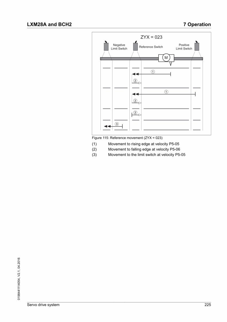
M
NegativeLimit Switch
PositiveLimit SwitchReference Switch
�
�
�
�
�
�
ZYX = 023
Figure 115: Reference movement (ZYX = 023)
(1) Movement to rising edge at velocity P5-05(2) Movement to falling edge at velocity P5-06(3) Movement to the limit switch at velocity P5-05
LXM28A and BCH2 7 Operation
Servo drive system 225
0198
4411
1405
4, V
2.1,
04.
2016

M
NegativeLimit Switch
PositiveLimit SwitchReference Switch
�
�
�
�
�
ZYX = 103
�
�
�
�
�
�
�
�
Figure 116: Reference movement (ZYX = 103)
(1) Movement to rising edge at velocity P5-05(2) Movement to falling edge at velocity P5-05(3) Movement to the index pulse at velocity P5-06(4) Movement to the limit switch at velocity P5-05
7 Operation LXM28A and BCH2
226 Servo drive system
0198
4411
1405
4, V
2.1,
04.
2016

M
NegativeLimit Switch
PositiveLimit SwitchReference Switch
�
�
�
�
ZYX = 113
�
�
�
�
�
�
�
�
�
�
Figure 117: Reference movement (ZYX = 113)
(1) Movement to rising edge at velocity P5-05(2) Movement to the index pulse at velocity P5-06(3) Movement to falling edge at velocity P5-05(4) Movement to the limit switch at velocity P5-05
LXM28A and BCH2 7 Operation
Servo drive system 227
0198
4411
1405
4, V
2.1,
04.
2016

M
NegativeLimit Switch
PositiveLimit SwitchReference Switch
�
�
�
�
�
ZYX = 123
�
�
�
�
�
Figure 118: Reference movement (ZYX = 123)
(1) Movement to rising edge at velocity P5-05(2) Movement to falling edge at velocity P5-06(3) Movement to the limit switch at velocity P5-05
7 Operation LXM28A and BCH2
228 Servo drive system
0198
4411
1405
4, V
2.1,
04.
2016

Reference movement to the indexpulse in positive direction
The following illustrations show reference movements to the indexpulse in positive direction from different starting positions.
M
NegativeLimit Switch
PositiveLimit Switch
�
�
�
ZYX = 0-4
Figure 119: Reference movement (ZYX = 0-4)
(1) Movement to the next index pulse at velocity P5-06(2) Movement to the limit switch at velocity P5-06
M
NegativeLimit Switch
PositiveLimit Switch
�
�
�
�
ZYX = 1-4
Figure 120: Reference movement (ZYX = 1-4)
(1) Movement to the next index pulse at velocity P5-06(2) Movement to the limit switch at velocity P5-06
LXM28A and BCH2 7 Operation
Servo drive system 229
0198
4411
1405
4, V
2.1,
04.
2016

Reference movement to the indexpulse in negative direction
The following illustrations show reference movements to the indexpulse in negative direction from different starting positions.
M
NegativeLimit Switch
PositiveLimit Switch
�
�
�
ZYX = 0-5
Figure 121: Reference movement (ZYX = 0-5)
(1) Movement to the next index pulse at velocity P5-06(2) Movement to the limit switch at velocity P5-06
M
NegativeLimit Switch
PositiveLimit Switch
�
�
�
�
ZYX = 1-5
Figure 122: Reference movement (ZYX = 1-5)
(1) Movement to the next index pulse at velocity P5-06(2) Movement to the limit switch at velocity P5-06
7 Operation LXM28A and BCH2
230 Servo drive system
0198
4411
1405
4, V
2.1,
04.
2016

Reference movement in positivedirection to the falling edge of the
reference switch
The following illustrations show reference movements to the fallingedge of the reference switch in positive direction from different startingpositions.
M
NegativeLimit Switch
PositiveLimit SwitchReference Switch
�
ZYX = 006
�
�
�
�
�
�
�
�
�
Figure 123: Reference movement (ZYX = 006)
(1) Movement to falling edge at velocity P5-05(2) Movement to rising edge at velocity P5-05(3) Movement to the index pulse at velocity P5-06(4) Movement to the limit switch at velocity P5-05
LXM28A and BCH2 7 Operation
Servo drive system 231
0198
4411
1405
4, V
2.1,
04.
2016

M
NegativeLimit Switch
PositiveLimit SwitchReference Switch
�
�
�
�
�
�
�
ZYX = 016
Figure 124: Reference movement (ZYX = 016)
(1) Movement to falling edge at velocity P5-05(2) Movement to the index pulse at velocity P5-06(3) Movement to the limit switch at velocity P5-05
M
NegativeLimit Switch
PositiveLimit SwitchReference Switch
�
�
�
�
�
�
ZYX = 026
Figure 125: Reference movement (ZYX = 026)
(1) Movement to rising edge at velocity P5-05(2) Movement to falling edge at velocity P5-06(3) Movement to the limit switch at velocity P5-05
7 Operation LXM28A and BCH2
232 Servo drive system
0198
4411
1405
4, V
2.1,
04.
2016

M
NegativeLimit Switch
PositiveLimit SwitchReference Switch
ZYX = 106
�
�
�
�
�
�
�
�
�
�
�
�
�
�
Figure 126: Reference movement (ZYX = 106)
(1) Movement to falling edge at velocity P5-05(2) Movement to rising edge at velocity P5-05(3) Movement to the index pulse at velocity P5-06(4) Movement to the limit switch at velocity P5-05
LXM28A and BCH2 7 Operation
Servo drive system 233
0198
4411
1405
4, V
2.1,
04.
2016

M
NegativeLimit Switch
PositiveLimit SwitchReference Switch
ZYX = 116
�
�
�
�
�
�
�
�
�
�
�
�
�
Figure 127: Reference movement (ZYX = 116)
(1) Movement to falling edge at velocity P5-05(2) Movement to the index pulse at velocity P5-06(3) Movement to the limit switch at velocity P5-05(4) Movement to rising edge at velocity P5-05
7 Operation LXM28A and BCH2
234 Servo drive system
0198
4411
1405
4, V
2.1,
04.
2016

M
NegativeLimit Switch
PositiveLimit SwitchReference Switch
�
�
�
�
�
ZYX = 126
�
�
�
�
�
Figure 128: Reference movement (ZYX = 126)
(1) Movement to rising edge at velocity P5-05(2) Movement to falling edge at velocity P5-06(3) Movement to the limit switch at velocity P5-05
LXM28A and BCH2 7 Operation
Servo drive system 235
0198
4411
1405
4, V
2.1,
04.
2016

Reference movement in negativedirection to the falling edge of the
reference switch
The following illustrations show reference movements to the fallingedge of the reference switch in negative direction from different start-ing positions.
M
NegativeLimit Switch
PositiveLimit SwitchReference Switch
�
ZYX = 007
�
�
�
�
�
�
�
�
�
Figure 129: Reference movement (ZYX = 007)
(1) Movement to falling edge at velocity P5-05(2) Movement to rising edge at velocity P5-05(3) Movement to the index pulse at velocity P5-06(4) Movement to the limit switch at velocity P5-05
7 Operation LXM28A and BCH2
236 Servo drive system
0198
4411
1405
4, V
2.1,
04.
2016

M
NegativeLimit Switch
PositiveLimit SwitchReference Switch
�
�
�
�
�
�
�
ZYX = 017
Figure 130: Reference movement (ZYX = 017)
(1) Movement to falling edge at velocity P5-05(2) Movement to the index pulse at velocity P5-06(3) Movement to the limit switch at velocity P5-05
M
NegativeLimit Switch
PositiveLimit SwitchReference Switch
�
�
�
�
�
�
ZYX = 027
Figure 131: Reference movement (ZYX = 027)
(1) Movement to rising edge at velocity P5-05(2) Movement to falling edge at velocity P5-06(3) Movement to the limit switch at velocity P5-05
LXM28A and BCH2 7 Operation
Servo drive system 237
0198
4411
1405
4, V
2.1,
04.
2016

M
NegativeLimit Switch
PositiveLimit SwitchReference Switch
ZYX = 107
�
�
�
�
�
�
�
�
�
�
�
�
�
�
Figure 132: Reference movement (ZYX = 107)
(1) Movement to falling edge at velocity P5-05(2) Movement to rising edge at velocity P5-05(3) Movement to the index pulse at velocity P5-06(4) Movement to the limit switch at velocity P5-05
7 Operation LXM28A and BCH2
238 Servo drive system
0198
4411
1405
4, V
2.1,
04.
2016

M
NegativeLimit Switch
PositiveLimit SwitchReference Switch
ZYX = 117
�
�
�
�
�
�
�
�
�
�
�
�
�
Figure 133: Reference movement (ZYX = 117)
(1) Movement to falling edge at velocity P5-05(2) Movement to the index pulse at velocity P5-06(3) Movement to the limit switch at velocity P5-05(4) Movement to rising edge at velocity P5-05
LXM28A and BCH2 7 Operation
Servo drive system 239
0198
4411
1405
4, V
2.1,
04.
2016

M
NegativeLimit Switch
PositiveLimit SwitchReference Switch
�
�
�
�
�
ZYX = 127
�
�
�
�
�
Figure 134: Reference movement (ZYX = 127)
(1) Movement to rising edge at velocity P5-05(2) Movement to falling edge at velocity P5-06(3) Movement to the limit switch at velocity P5-05
Position setting By means of position setting, the current motor position is set to theposition value in parameter P6-00. This also defines the zero point.
Position setting is only possible when the motor is at a standstill. Anyactive position deviation remains active and can still be compensatedfor by the position controller after position setting.
Parameter name Description UnitMinimum valueFactory settingMaximum valueHMI Format
Data typeR/WPersistent
Parameteraddress via field-bus
P6-00ODAT
Position of Homing Data Set
Applicable operating mode: PS
After a successful reference movement, thisposition is automatically set at the referencepoint.
Bits 0 ... 31: Position
PUU-214748364702147483647Decimal
s32RWper.
Modbus 700h CANopen 4600h
7 Operation LXM28A and BCH2
240 Servo drive system
0198
4411
1405
4, V
2.1,
04.
2016

7.3.5 Operating modes Velocity (V) and Velocity Zero (Vz)
Description In the operating mode Velocity (V), a movement is made with a speci-fied target velocity.
Source of reference value signals In the operating mode Velocity (V), the source of the reference valuesignals is either the analog input V_REF or one of the three values setvia the parameters P1-09 to P1-11.
In the operating mode Velocity Zero (Vz), the source of the referencevalue signals is either one of the three values set via the parametersP1-09 to P1-11 or the fixed target velocity 0.
The values of the parameters P1-09 to P1-11 can be selected viathe signal input functions SPD0 and SPD1.
The signal input functions SPD0 and SPD1 take priority over the refer-ence value signal at the analog input V_REF.
The target velocity is selected via the signal input functions SPD0(LSB) and SPD1 (MSB) (bit-coded):
See chapter "7.4.2 Parameterization of the signal input functions" foradditional information on the parameterizable signal input functions.
- Signal state of the digitalsignal inputs
Target velocity via: Range
SPD1 SPD0S1 0 0 Operating mode
Velocity (V)Voltage between V_REF(pin 42) and GND (pin 44)
-10V ... 10V
Operating modeVelocity Zero (Vz)
0 min-1
S2 0 1 Internal parameters P1-09 -60000 ... 60000 *0.1 min-1
S3 1 0 P1-10S4 1 1 P1-11
Scaling of the analog input V_REF The parameter P1-40 lets you set the velocity corresponding to 10 V.This results in a linear scaling for the analog input V_REF.
LXM28A and BCH2 7 Operation
Servo drive system 241
0198
4411
1405
4, V
2.1,
04.
2016

105
-10 -5
P1-40
V_REF [V]
5000 min-1
3000 min-1
-5000 min-1
-3000 min-1
Figure 135: Scaling of the analog input V_REF via P1-40
Parameter name Description UnitMinimum valueFactory settingMaximum valueHMI Format
Data typeR/WPersistent
Parameteraddress via field-bus
P1-40VCM
Velocity Target Value and Velocity Limitation10 V
Applicable operating mode: PT, PS, V, T
In the operating mode V, this parameterspecifies the target velocity that corre-sponds to the maximum input voltage of 10V.
In the operating mode T, this parameterspecifies the velocity limitation that corre-sponds to the maximum input voltage of 10V.
Example: If the value of this parameter is3000 in the operating mode V and if theinput voltage is 10 V, the target velocity is3000 min-1.
rpm0-10001Decimal
s32RWper.
Modbus 250h CANopen 4128h
7 Operation LXM28A and BCH2
242 Servo drive system
0198
4411
1405
4, V
2.1,
04.
2016

Example The illustration below shows how the target velocities are switched bymeans of the signal input functions SPD0,SPD1 and SON.
SPD0
SPD1
SON
OFF
OFF
OFF ON
ON
ON
ON
S2 (P1-09)
S3 (P1-10)
S4 (P1-11)
S1
Figure 136: Operating modes Velocity (V) and Velocity Zero (Vz)
See chapter "7.4 Setting the digital signal inputs and signal outputs"for additional information.
LXM28A and BCH2 7 Operation
Servo drive system 243
0198
4411
1405
4, V
2.1,
04.
2016

7.3.5.1 Acceleration and decelerationThe parameters P1-34 and P1-35 allow you to set the accelerationand deceleration.
t
v
P1-34 P1-35
Figure 137: Acceleration and deceleration
Parameter name Description UnitMinimum valueFactory settingMaximum valueHMI Format
Data typeR/WPersistent
Parameteraddress via field-bus
P1-34TACC
Acceleration Period
Applicable operating mode: PT, V
The acceleration period is the time in milli-seconds required to accelerate from motorstandstill to 6000 min-1.
For operating mode V, this parameter speci-fies the acceleration. If the target velocity issupplied as an analog signal, the maximumvalue of this parameter is automatically limi-ted to 20000.
For operating mode PT, this parameterspecifies an acceleration limitation for thepulses at the PTI interface.
ms63065500Decimal
u16RWper.
Modbus 244h CANopen 4122h
P1-35TDEC
Deceleration Period
Applicable operating mode: PT, V
The deceleration period is the time in milli-seconds required to decelerate from6000 min-1 to motor standstill.
For operating mode V, this parameter speci-fies the deceleration. If the target velocity issupplied as an analog signal, the maximumvalue of this parameter is automatically limi-ted to 20000.
For operating mode PT, this parameterspecifies a deceleration limitation for thepulses at the PTI interface.
ms63065500Decimal
u16RWper.
Modbus 246h CANopen 4123h
7 Operation LXM28A and BCH2
244 Servo drive system
0198
4411
1405
4, V
2.1,
04.
2016

7.3.6 Operating modes Torque (T) and Torque Zero (Tz)
Description In the operating mode Torque (T), a movement is made with a speci-fied target torque. The target torque is specified in percent of the nom-inal torque of the motor.
The operating modes Torque (T) and Torque (Tz) and the dual operat-ing modes with Torque (T) and Torque (Tz) do not provide decelera-tion functionality in response to a power stage disable request. Inthese operating modes, the motor coasts down to a standstill inresponse to a power stage disable request. You must install additionalequipment such as a dedicated service brake if your applicationrequires faster deceleration of the load.
WARNINGUNINTENDED EQUIPMENT OPERATION
• Verify that all loads come to a secure standstill when the powerstage is disabled in the operating modes Torque (T) and Torque(Tz) and in all dual-mode operating modes with Torque (T) andTorque (Tz) by performing comprehensive commissioning testsunder maximum load conditions.
• During commissioning, trigger all signals and simulate all condi-tions that cause a power stage disable request in order to verifythat all loads come to a secure standstill when the power stage isdisabled in the operating modes Torque (T) and Torque (Tz) andin all dual-mode operating modes with Torque (T) and Torque (Tz)under maximum load conditions.
• Install a dedicated service brake if coasting does not meet thedeceleration requirements of your application.
Failure to follow these instructions can result in death, seriousinjury, or equipment damage.
LXM28A and BCH2 7 Operation
Servo drive system 245
0198
4411
1405
4, V
2.1,
04.
2016

Source of reference value signals In the operating mode Torque (T), the source of the reference valuesignals is either the analog input T_REF or one of the three values setvia the parameters P1-12 to P1-14.
In the operating mode Torque Zero (Tz), the source of the referencevalue signals is either one of the three values set via the parametersP1-12 to P1-14 or the fixed target torque 0 %.
The values of the parameters P1-12 to P1-14 can be selected viathe signal input functions TCM0 and TCM1.
The signal input functions TCM0 and TCM1 take priority over the ref-erence value signal of the analog input T_REF.
The target torque is selected via the signal input functions TCM0(LSB) and TCM1 (MSB) (bit-coded):
See chapter "7.4.2 Parameterization of the signal input functions" foradditional information on the parameterizable signal input functions.
- Signal state of the digitalsignal inputs
Target torque is provided via: Range
TCM1 TCM0T1 0 0 Operating mode
Torque (T)Voltage between T_REF(pin 18) and GND (pin 19)
-10V ... 10V
Operating modeTorque Zero (Tz)
0 %
T2 0 1 Internal parameters P1-12 -300 ... 300%
T3 1 0 P1-13T4 1 1 P1-14
7 Operation LXM28A and BCH2
246 Servo drive system
0198
4411
1405
4, V
2.1,
04.
2016

Scaling of the analog input T_REF The parameter P1-41 lets you set the torque corresponding to 10 V.This results in a linear scaling for the analog input T_REF.
105
-100 %
-300 %
100 %
300 %
-10 -5
P1-41
T_REF [V]
Figure 138: Scaling of the analog input T_REF via P1-41
Parameter name Description UnitMinimum valueFactory settingMaximum valueHMI Format
Data typeR/WPersistent
Parameteraddress via field-bus
P1-41TCM
Torque Target Value and Torque Limitation10 V
Applicable operating mode: PT, PS, V, T
In the operating mode T, this parameterspecifies the target torque that correspondsto the maximum input voltage of 10 V.
In the operating modes PT, PS and V, thisparameter specifies the torque limitationthat corresponds to the maximum input volt-age of 10 V.
Example: If the value of this parameter is100 in the operating mode T and if the inputvoltage is 10 V, the target torque is 100 % ofthe nominal torque.
Setting can only be changed if power stageis disabled.
%01001000Decimal
u16RWper.
Modbus 252h CANopen 4129h
LXM28A and BCH2 7 Operation
Servo drive system 247
0198
4411
1405
4, V
2.1,
04.
2016

Example The illustration below shows how the target torque is switched bymeans of the signal input functions TCM0,TCM1 and SON.
TCM0
TCM1
SON
OFF
OFF
OFF ON
ON
ON
ON
T2 (P1-12)
T3 (P1-13)
T4 (P1-14)
T1
Figure 139: Operating modes Torque (T) and Torque Zero (Tz)
See chapter "7.4 Setting the digital signal inputs and signal outputs"for additional information.
7 Operation LXM28A and BCH2
248 Servo drive system
0198
4411
1405
4, V
2.1,
04.
2016

7.4 Setting the digital signal inputs and signal outputs
The functions of the inputs and outputs depend on the selected oper-ating mode and the settings of the corresponding parameters.
WARNINGUNINTENDED EQUIPMENT OPERATION
• Verify that the wiring is appropriate for the settings.• Only start the system if there are no persons or obstructions in
the zone of operation.• When commissioning, carefully run tests for all operating states
and potential error situations.
Failure to follow these instructions can result in death, seriousinjury, or equipment damage.
Signal function Various signal functions can be assigned to the digital signal inputsand digital signal outputs.
Depending on the selected operating mode, different functions areassigned to the digital signal inputs and digital signal outputs.
LXM28A and BCH2 7 Operation
Servo drive system 249
0198
4411
1405
4, V
2.1,
04.
2016

7.4.1 Default presets of the signal inputs
The table below shows the default presets of the digital signal inputsdepending on the selected operating mode:
Setting AforP2-10 ... P2-17
Shortname
Name PT PS V T Vz Tz PTV
PTT
PSV
PST
VT
CANopen
01h SON Servo ON DI1 DI1 DI1 DI1 DI1 DI1 DI1 DI1 DI1 DI1 DI1 -
02h FAULT_RESET
Fault Reset DI5 DI5 DI5 DI5 DI5 DI5 - - - - - -
03h GAINUP Increase Gain - - - - - - - - - - - -
04h CLRPOSDEV
Clear Position Devia-tion
DI2 - - - - - DI2 DI2 - - - -
05h ZCLAMP Zero Clamp - - - - - - - - - - - -
06h INVDIR-ROT
Inverse Direction OfRotation
- - - - - - - - - - - -
07h HALT Halt - - - - - - - - - - - -
08h CTRG Start Data Set - DI2 - - - - - - DI2 DI2 -
09h TRQLM Activate Torque Limit - - DI2 - DI2 - - - - - - -
10h SPDLM Activate Speed Limit - - - DI2 - DI2 - - - - - -
11h POS0 Data Set Bit 0 - DI3 - - - - - - DI3 DI3 - -
12h POS1 Data Set Bit 1 - DI4 - - - - - - DI4 DI4 - -
13h POS2 Data Set Bit 2 - - - - - - - - - - - -
14h SPD0 Speed Reference ValueBit 0
- - DI3 - DI3 - DI3 - DI5 - DI3 -
15h SPD1 Speed Reference ValueBit 1
- - DI4 - DI4 - DI4 - DI6 - DI4 -
16h TCM0 Torque ReferenceValue Bit 0
DI3 - - DI3 - DI3 - DI3 - DI5 DI5 -
17h TCM1 Torque ReferenceValue Bit 1
DI4 - - DI4 - DI4 - DI4 - DI6 DI6 -
18h V-Px Velocity - Position - - - - - - DI7 - DI7 - - -
19h V-T Velocity - Torque - - - - - - - - - - DI7 -
1Ah POS3 Data Set Bit 3 - - - - - - - - - - - -
1Bh POS4 Data Set Bit 4 - - - - - - - - - - - -
1Ch TPROB1 Touch Probe 1 - - - - - - - - - - - -
20h T-Px Torque - Position - - - - - - - DI7 - DI7 - -
21h OPST Stop and DisablePower Stage
DI8 DI8 DI8 DI8 DI8 DI8 DI8 DI8 DI8 DI8 DI8 DI8
22h CWL(NL) Negative Limit Switch(NL/LIMN)
DI6 DI6 DI6 DI6 DI6 DI6 - - - - - DI6
23h CCWL(PL)
Positive Limit Switch(PL/LIMP)
DI7 DI7 DI7 DI7 DI7 DI7 - - - - - DI7
24h ORGP Reference Switch - - - - - - - - - - - DI5
7 Operation LXM28A and BCH2
250 Servo drive system
0198
4411
1405
4, V
2.1,
04.
2016

Setting AforP2-10 ... P2-17
Shortname
Name PT PS V T Vz Tz PTV
PTT
PSV
PST
VT
CANopen
27h GOTO-HOME
Move To Home Position - - - - - - - - - - - -
2Ch PTCMS Type of pulses for oper-ating mode Pulse Train(PT) (OFF: Low-speedpulses, ON: High-Speed pulses)
- - - - - - - - - - - -
37h JOGP Jog Positive - - - - - - - - - - - -
38h JOGN Jog Negative - - - - - - - - - - - -
39h STEPU Next Data Set - - - - - - - - - - - -
40h STEPD Previous Data Set - - - - - - - - - - - -
41h STEPB First Data Set - - - - - - - - - - - -
42h AUTOR Automatic PositionSequence: Start withfirst data set, repeatsequence
- - - - - - - - - - - -
43h GNUM0 Numerator Bit 0 Elec-tronic Gear Ratio
- - - - - - - - - - - -
44h GNUM1 Numerator Bit 1 Elec-tronic Gear Ratio
- - - - - - - - - - - -
45h INHP Pulse Inhibit - - - - - - - - - - - -
46h STOP Stop Motor (operatingmode PS only)
- - - - - - - - - - - -
LXM28A and BCH2 7 Operation
Servo drive system 251
0198
4411
1405
4, V
2.1,
04.
2016

7.4.2 Parameterization of the signal input functions
Parameterization The signal input functions for the inputs DI1 ... DI8 are configured viathe parameters P2-10 ... P2-17.
A signal input function can only be assigned to one of the signalinputs.
ON
OFF
ON
OFF
1: Normally open
0: Normally closed
A (Input Function)
B
not used
The operating modes Torque (T) and Torque (Tz) and the dual operat-ing modes with Torque (T) and Torque (Tz) do not provide decelera-tion functionality in response to a power stage disable request. Inthese operating modes, the motor coasts down to a standstill inresponse to a power stage disable request. You must install additionalequipment such as a dedicated service brake if your applicationrequires faster deceleration of the load.
WARNINGUNINTENDED EQUIPMENT OPERATION
• Verify that all loads come to a secure standstill when the powerstage is disabled in the operating modes Torque (T) and Torque(Tz) and in all dual-mode operating modes with Torque (T) andTorque (Tz) by performing comprehensive commissioning testsunder maximum load conditions.
• During commissioning, trigger all signals and simulate all condi-tions that cause a power stage disable request in order to verifythat all loads come to a secure standstill when the power stage isdisabled in the operating modes Torque (T) and Torque (Tz) andin all dual-mode operating modes with Torque (T) and Torque (Tz)under maximum load conditions.
• Install a dedicated service brake if coasting does not meet thedeceleration requirements of your application.
Failure to follow these instructions can result in death, seriousinjury, or equipment damage.
The table below provides an overview of the possible signal inputfunctions:
7 Operation LXM28A and BCH2
252 Servo drive system
0198
4411
1405
4, V
2.1,
04.
2016

Setting A forP2-10 ... P2-17
Short name Name Description
01h SON Servo ON The signal input function SON enables the power stage (operatingstate Operation Enabled). The signal input function SON is only avail-able if no detected errors are present.
02h FAULT_RESET
Fault Reset The signal input function FAULT_RESET performs a Fault Reset. Thecause of the error must have been removed before a Fault Reset isperformed.
03h GAINUP Increase Gain The signal input function GAINUP increases the control gain accord-ing to the values and conditions set via parameter P2-27.
04h CLRPOS-DEV
Clear PositionDeviation
The signal input function CLRPOSDEV resets the position deviationto zero as set via parameter P2-50.
05h ZCLAMP Zero Clamp The signal input function ZCLAMP stops the motor. The velocity ofthe motor must be below the velocity value set via parameter P1-38.
06h INVDIRROT Inverse Direc-tion Of Rotation
The signal input function INVDIRROT inverts the direction of rotationof the motor. The signal input function INVDIRROT is available in theoperating modes Velocity (V) and Torque (T).
07h HALT Halt The signal input function HALT interrupts the movement with thedeceleration ramp set via the parameter P1-68. The movement isresumed when the signal input function is no longer active.
08h CTRG Start Data Set The signal input function CTRG starts the selected data set in theoperating mode Position Sequence (PS). See chapter"7.3.4 Operating mode Position Sequence (PS)" for additional infor-mation.
09h TRQLM Activate TorqueLimit
The signal input function TRQLM activates the torque limitations setvia parameters P1-12 ... P1-14. You can also use the parameterP1-02 to activate the torque limitations set via parameters P1-12 ...P1-14.
10h SPDLM Activate SpeedLimit
The signal input function SPDLM activates the velocity limitations setvia parameters P1-09 ... P1-11. You can also use the parameterP1-02 to activate the velocity limitations set via parameters P1-09 ...P1-11.
11h POS0 Data Set Bit 0 The signal input functions POS0 ... POS4 represent bits 0 ... 4required to select one of the 32 data sets available in the operatingmode Position Sequence (PS). See chapter"7.3.4 Operating mode Position Sequence (PS)" for additional infor-mation.
12h POS1 Data Set Bit 1 The signal input functions POS0 ... POS4 represent bits 0 ... 4required to select one of the 32 data sets available in the operatingmode Position Sequence (PS). See chapter"7.3.4 Operating mode Position Sequence (PS)" for additional infor-mation.
13h POS2 Data Set Bit 2 The signal input functions POS0 ... POS4 represent bits 0 ... 4required to select one of the 32 data sets available in the operatingmode Position Sequence (PS). See chapter"7.3.4 Operating mode Position Sequence (PS)" for additional infor-mation.
14h SPD0 Speed Refer-ence Value Bit 0
The signal input functions SPD0 and SPD1 represent bits 0 and 1 toselect one of the three velocity reference values available in the oper-ating mode Velocity (V). See chapter"7.3.5 Operating modes Velocity (V) and Velocity Zero (Vz)" for addi-tional information.
15h SPD1 Speed Refer-ence Value Bit 1
The signal input functions SPD0 and SPD1 represent bits 0 and 1 toselect one of the three velocity reference values available in the oper-ating mode Velocity (V). See chapter"7.3.5 Operating modes Velocity (V) and Velocity Zero (Vz)" for addi-tional information.
LXM28A and BCH2 7 Operation
Servo drive system 253
0198
4411
1405
4, V
2.1,
04.
2016

Setting A forP2-10 ... P2-17
Short name Name Description
16h TCM0 Torque Refer-ence Value Bit 0
The signal input functions TCM0 and TCM1 represent bits 0 and 1 toselect one of the three torque reference values available in the oper-ating mode Torque (T). See chapter"7.3.6 Operating modes Torque (T) and Torque Zero (Tz)" for addi-tional information.
17h TCM1 Torque Refer-ence Value Bit 1
The signal input functions TCM0 and TCM1 represent bits 0 and 1 toselect one of the three torque reference values available in the oper-ating mode Torque (T). See chapter"7.3.6 Operating modes Torque (T) and Torque Zero (Tz)" for addi-tional information.
18h V-Px Velocity - Posi-tion
Operating mode switching between Velocity (V) and Pulse Train (PT)or between Velocity (V) and Position Sequence (PS) , see chapter"7.3.1 Setting the operating mode".(OFF: Velocity (V), ON: Pulse Train (PT) or Position Sequence (PS),depending on P1-01)
19h V-T Velocity - Torque Operating mode switching between Velocity (V) and Torque (T), seechapter "7.3.1 Setting the operating mode".(OFF: Velocity (V), ON: Pulse Torque (T))
1Ah POS3 Data Set Bit 3 The signal input functions POS0 ... POS4 represent bits 0 ... 4required to select one of the 32 data sets available in the operatingmode Position Sequence (PS). See chapter"7.3.4 Operating mode Position Sequence (PS)" for additional infor-mation.
1Bh POS4 Data Set Bit 4 The signal input functions POS0 ... POS4 represent bits 0 ... 4required to select one of the 32 data sets available in the operatingmode Position Sequence (PS). See chapter"7.3.4 Operating mode Position Sequence (PS)" for additional infor-mation.
1Ch TPROB1 Touch Probe 1 The signal input function TPROB1 is used to trigger the Position Cap-ture function. See the sections on the parameters P5-37 ... P5-39 foradditional information.
1Dh TPROB2 Touch Probe 2 The signal input function TPROB2 is used to trigger the Position Cap-ture function. See the sections on the parameters P5-37 ... P5-39 foradditional information.
20h T-Px Torque - Posi-tion
Operating mode switching between Torque (T) and Pulse Train (PT)or between Torque (T) and Position Sequence (PS) , see chapter"7.3.1 Setting the operating mode".(OFF: Torque (T), ON: Pulse Train (PT) or Position Sequence (PS),depending on P1-01)
21h OPST Stop and Disa-ble Power Stage
The signal input function OPST stops the motor with the decelerationramp set via the parameter P1-68 and then disables the powerstage.
22h CWL(NL) Negative LimitSwitch (NL/LIMN)
Negative limit switch (NL/LIMN). When the signal input is activated,an alert is triggered. The deceleration ramp is specified via parameterP5-25.
23h CCWL(PL) Positive LimitSwitch (PL/LIMP)
Positive limit switch (PL/LIMP). When the signal input is activated, analert is triggered. The deceleration ramp is specified via parameterP5-26.
24h ORGP ReferenceSwitch
The signal input function ORGP is used for the reference switch. Seechapter "7.3.4 Operating mode Position Sequence (PS)" for additionalinformation.
27h GOTO-HOME
Move To HomePosition
The signal input function GOTOHOME triggers a movement to theHome position set via the parameter P5-04.
7 Operation LXM28A and BCH2
254 Servo drive system
0198
4411
1405
4, V
2.1,
04.
2016

Setting A forP2-10 ... P2-17
Short name Name Description
2Ch PTCMS Type of pulsesfor operatingmode PulseTrain (PT) (OFF:Low-speed pul-ses, ON: High-Speed pulses)
The signal input function PTCMS selects the type of pulses for theoperating mode Pulse Train PT (OFF: Low-speed pulses, ON: High-speed pulses). You can also use the parameter P1-00 to select thetype of pulses.
37h JOGP Jog Positive The signal input function JOGP triggers a Jog movement in positivedirection if the value determining the direction of movement in theparameter P1-01 is set to the default value.
38h JOGN Jog Negative The signal input function JOGN triggers a Jog movement in negativedirection if the value determining the direction of movement in theparameter P1-01 is set to the default value.
39h STEPU Next Data Set The signal input function STEPU starts the next data set in the oper-ating mode Position Sequence (PS).
40h STEPD Previous DataSet
The signal input function STEPD starts the previous data set in theoperating mode Position Sequence (PS).
41h STEPB First Data Set The signal input function STEPB starts the first data set in the operat-ing mode Position Sequence (PS).
42h AUTOR Automatic Posi-tion Sequence:Start with firstdata set, repeatsequence
The signal input function AUTOR starts a sequence of data sets fromthe first data set in the operating mode Position Sequence (PS). Thesequence is repeated as long a the signal input function AUTOR isactive.
43h GNUM0 Numerator Bit 0Electronic GearRatio
The signal input functions GNUM0 and GNUM1 represent bits 0 and1 to select one of the four numerators set via the parameters P1-44,P2-60 ... P2-62. The denominator is set via the parameter P1-45 .The ratios are used as gear factors in the operating mode Pulse Train(PT) and as scaling factors. See chapters "7.3.3.2 Gear ratio" and"7.3.4.2 Scaling" for additional information.
44h GNUM1 Numerator Bit 1Electronic GearRatio
The signal input functions GNUM0 and GNUM1 represent bits 0 and1 to select one of the four numerators set via the parameters P1-44,P2-60 ... P2-62. The denominator is set via the parameter P1-45.The ratios are used as gear factors in the operating mode Pulse Train(PT) and as scaling factors. See chapters "7.3.3.2 Gear ratio" and"7.3.4.2 Scaling" for additional information.
45h INHP Pulse Inhibit The signal input function INHP is used in the operating mode PulseTrain (PT) to block pulses received as reference signals. If the signalinput function is active, the pulses are no longer evaluated and themotor coasts down.
46h STOP Stop Motor(operating modePS only)
The signal input function STOP stops the motor with the decelerationramp set via the parameter P5-20. The power stage remains ena-bled. The signal input function STOP is available in the operatingmode Position Sequence (PS).
LXM28A and BCH2 7 Operation
Servo drive system 255
0198
4411
1405
4, V
2.1,
04.
2016

7.4.3 Default presets of the signal outputs
The table below shows the default presets of the digital signal outputsdepending on the selected operating mode:
Setting AforP2-18 ... P2-22
Shortname
Name PT PS V T Vz Tz PTV
PTT
PSV
PST
VT
CANopen
01h SRDY Servo Ready DO1 DO1 DO1 DO1 DO1 DO1 DO1 DO1 DO1 DO1 DO1 DO1
02h SON Servo On - - - - - - - - - - - -
03h ZSPD Zero Speed DO2 DO2 DO2 DO2 DO2 DO2 DO2 DO2 DO2 DO2 DO2 -
04h TSPD SpeedReached
- - DO3 DO3 DO3 DO3 DO3 DO3 DO3 DO3 DO3 -
05h TPOS MovementCompleted
DO4 DO4 - - - - DO4 DO4 DO4 DO4 -
06h TQL Torque LimitReached
- - - - - - - - - - - -
07h ERROR Error Detected DO5 DO5 DO5 DO5 DO5 DO5 DO5 DO5 DO5 DO5 DO5 DO5
08h BRKR Holding BrakeControl
- - DO4 DO4 DO4 DO4 - - - - - -
09h HOMED_OK
Homing Com-pleted
DO3 DO3 - - - - - - - - - -
10h OLW Motor Over-load Alert
- - - - - - - - - - - -
11h WARN Alert Signalactivated
- - - - - - - - - - - -
12h OVF Position com-mand overflow
- - - - - - - - - - - -
13h SCWL(SNL)
Negative Soft-ware LimitSwitchReached
- - - - - - - - - - - -
14h SCCWL(SPL)
Positive Soft-ware LimitSwitchReached
- - - - - - - - - - - -
15h CMD_OK
Data set com-pleted
- - - - - - - - - - - -
16h CAP_OK Capture com-pleted
- - - - - - - - - - - -
17h MC_OK Motion controlcompletedoutput
- - - - - - - - - - - -
19h SP_OK Speedreached out-put
- - - - - - - - - - - -
7 Operation LXM28A and BCH2
256 Servo drive system
0198
4411
1405
4, V
2.1,
04.
2016

Setting AforP2-18 ... P2-22
Shortname
Name PT PS V T Vz Tz PTV
PTT
PSV
PST
VT
CANopen
30h SDO_0 Output thestatus of bit 0of P4-06.
- - - - - - - - - - - -
31h SDO_1 Output thestatus of bit 1of P4-06.
- - - - - - - - - - - -
32h SDO_2 Output thestatus of bit 2of P4-06.
- - - - - - - - - - - -
33h SDO_3 Output thestatus of bit 3of P4-06.
- - - - - - - - - - - -
34h SDO_4 Output thestatus of bit 4of P4-06.
- - - - - - - - - - - -
35h SDO_5 Output thestatus of bit 5of P4-06.
- - - - - - - - - - - -
36h SDO_6 Output thestatus of bit 6of P4-06.
- - - - - - - - - - - -
37h SDO_7 Output thestatus of bit 7of P4-06.
- - - - - - - - - - - -
38h ... 3Fh - - - - - - - - - - - - - -
LXM28A and BCH2 7 Operation
Servo drive system 257
0198
4411
1405
4, V
2.1,
04.
2016

7.4.4 Parameterization of the signal output functions
Parameterization The signal output functions for the outputs DO1 ... DO5 are configuredvia the parameters P2-18 ... P2-22.
ON
OFF
ON
OFF
1: Normally open
0: Normally closed
A (Output Function)
B
not used
The table below provides an overview of the possible signal outputfunctions:
Setting A forP2-18 ... P2-22
Short name Name Description
01h SRDY Servo Ready The signal output function SRDY indicates that no errors are present,i.e. the drive is not in the operating state Fault.
02h SON Servo On The signal output function SON indicates that the drive is in the oper-ating state Operation Enabled .
03h ZSPD Zero Speed The signal output function ZSPD indicates that the velocity of themotor is less than the velocity value set via parameter P1-38 .
04h TSPD Speed Reached The signal output function TSPD indicates that the velocity of themotor is greater than the velocity value set via parameter P1-39 .
05h TPOS Movement Com-pleted
Operating mode Pulse Train (PT): The signal output function TPOSindicates that the position deviation is within the tolerance set via theparameter P1-54. Operating mode Position Sequence (PS): The sig-nal output function TPOS indicates that the position deviation at thetarget position is within the tolerance set via the parameter P1-54.
7 Operation LXM28A and BCH2
258 Servo drive system
0198
4411
1405
4, V
2.1,
04.
2016

Setting A forP2-18 ... P2-22
Short name Name Description
06h TQL Torque LimitReached
The signal output function TQL indicates that the torque of the motorhas reached the value set via parameters P1-12 ... P1-14 or an ana-log input.
07h ERROR Error Detected The signal output function ERROR indicates that an error has beendetected and that the drive has switched to the operating state Fault.See "9 Diagnostics and troubleshooting" for details.
08h BRKR Holding BrakeControl
The signal output function BRKR is used to control the holding brakewith the settings made via parameters P1-42 and P1-19. The holdingbrake must be must be connected to the output to which the signaloutput function BRKR is assigned. See chapter"5.4.1.11 Holding brake connection" for additional information.
09h HOMED_OK Homing Com-pleted
The signal output function HOMED_OK indicates that the homing pro-cedure has been successfully completed. The settings for Homing arespecified via parameters P5-04 ... P5-06. See chapter"7.3.4 Operating mode Position Sequence (PS)" for additional infor-mation.
10h OLW Motor OverloadAlert
The signal output function OLW indicates a motor overload condition.A threshold for the signal output function OLW can be set via parame-ter P1-28.
11h WARN Alert Signal acti-vated
The signal output function indicates that one of the following condi-tions has been detected: Hardware limit switch triggered, undervolt-age, Nodeguard alert, Operational Stop (OPST). See chapter"9 Diagnostics and troubleshooting" for additional information.
12h - - Reserved
13h SCWL(SNL) Negative Soft-ware LimitSwitch Reached
The signal output function SCWL(SNL) indicates that the negativesoftware limit switch set via parameter P5-09 has been reached.When the software limit switch is reached, an alert is triggered. Thedeceleration ramp is specified via parameter P5-23.
14h SCCWL(SPL)
Positive Soft-ware LimitSwitch Reached
The signal output function SCCWL(SPL) indicates that the positivesoftware limit switch set via parameter P5-08 has been reached.When the software limit switch is reached, an alert is triggered. Thedeceleration ramp is specified via parameter P5-24.
15h CMD_OK Data set com-pleted
The signal output function CMD_OK indicates that the data set includ-ing the waiting time has been successfully completed.
16h CAP_OK Capture comple-ted
The signal output function CAP_OK indicates that a position capture(Touch Probe) has been successfully completed. The settings forposition capture (Touch Probe) are specified via parameters P5-37 ...P5-39.
17h MC_OK Motion controlcompleted out-put
The signal output function MC_OK indicates that both the signal out-put functions CMD_OK and TPOS have been activated.
19h SP_OK Speed reachedoutput
The signal output function SP_OK indicates that the target velocityhas been reached. The velocity range for activating this signal outputfunction is set via parameter P1-47.
30h SDO_0 Output the sta-tus of bit 0 ofP4-06.
The signal output functions SDO_0 ... SDO_7 provide the bit pattern(bits 0 ... 7) required to determine the setting of the parameter P4-06.
31h SDO_1 Output the sta-tus of bit 1 ofP4-06.
The signal output functions SDO_0 ... SDO_7 provide the bit pattern(bits 0 ... 7) required to determine the setting of the parameter P4-06.
32h SDO_2 Output the sta-tus of bit 2 ofP4-06.
The signal output functions SDO_0 ... SDO_7 provide the bit pattern(bits 0 ... 7) required to determine the setting of the parameter P4-06.
LXM28A and BCH2 7 Operation
Servo drive system 259
0198
4411
1405
4, V
2.1,
04.
2016

Setting A forP2-18 ... P2-22
Short name Name Description
33h SDO_3 Output the sta-tus of bit 3 ofP4-06.
The signal output functions SDO_0 ... SDO_7 provide the bit pattern(bits 0 ... 7) required to determine the setting of the parameter P4-06.
34h SDO_4 Output the sta-tus of bit 4 ofP4-06.
The signal output functions SDO_0 ... SDO_7 provide the bit pattern(bits 0 ... 7) required to determine the setting of the parameter P4-06.
35h SDO_5 Output the sta-tus of bit 5 ofP4-06.
The signal output functions SDO_0 ... SDO_7 provide the bit pattern(bits 0 ... 7) required to determine the setting of the parameter P4-06.
36h SDO_6 Output the sta-tus of bit 6 ofP4-06.
The signal output functions SDO_0 ... SDO_7 provide the bit pattern(bits 0 ... 7) required to determine the setting of the parameter P4-06.
37h SDO_7 Output the sta-tus of bit 7 ofP4-06.
The signal output functions SDO_0 ... SDO_7 provide the bit pattern(bits 0 ... 7) required to determine the setting of the parameter P4-06.
38h ... 3Fh - - Reserved
7 Operation LXM28A and BCH2
260 Servo drive system
0198
4411
1405
4, V
2.1,
04.
2016

7.5 Functions for target value processing
7.5.1 Interrupting a movement with HALT
The HALT signal input function is available in the operating mode PTonly.
With the signal input function HALT, the ongoing movement is interrup-ted. When the signal input function HALT is no longer active, themovement is resumed from the point where it was interrupted.
The movement is interrupted via a deceleration ramp. The decelera-tion ramp is specified via parameter P1-68.
In order to interrupt a movement via a signal input, you must firstparameterize the signal input function HALT, see chapter"7.4.2 Parameterization of the signal input functions".
NOTE: The pulses received while the HALT function is active areignored. When the HALT is no longer active, the drive will accept anyon-going pulse stream and start movement according to that stream.
WARNINGUNEXPECTED MOVEMENT OF MACHINERY
Prior to deactivating the HALT function, determine whether subse-quent movement will present a hazard within the zone of operation.
Failure to follow these instructions can result in death, seriousinjury, or equipment damage.
If there is uncertainty of the effect of the movement generated by anongoing pulse stream at the time of HALT deactivation, you must re-home the application.
7.5.2 Stopping a movement with OPST
With the signal input function OPST, the ongoing movement is stop-ped.
In order to stop a movement via a signal input, you must first parame-terize the signal input function OPST, see chapter"7.4.2 Parameterization of the signal input functions".
Depending on the operating mode, the movement is interrupted eithervia a deceleration ramp, or, as in the case of one of the torque modes,allowed to coast to a standstill. After that, the power stage is disabledonce the drive has determined that the motor is at standstill (definedas either a standstill or, as for operating mode Torque, after a 5 sec-ond timeout), and that the delay for applying the holding brake hasexpired.
An error, AL013, is detected and presented.
The deceleration ramp is specified via parameter P1-68.
After the OPST function is enabled, you must disable it and re-enablethe power stage for continued operation.
LXM28A and BCH2 7 Operation
Servo drive system 261
0198
4411
1405
4, V
2.1,
04.
2016

7.6 Setting a signal output via parameter
The digital signal outputs can be set via a parameter.
In order to set a digital signal output via the parameter, you must firstparameterize of of the signal output functions "SDO_0" ... "SDO_7",see chapter "7.4.4 Parameterization of the signal output functions".
The parameter P4-06 lets you set the digital signal outputs.
Parameter name Description UnitMinimum valueFactory settingMaximum valueHMI Format
Data typeR/WPersistent
Parameteraddress via field-bus
P4-06FOT
Setting a signal output via parameter
Applicable operating mode: PT, PS, V, T
This parameter lets you set those signaloutputs whose signal output functions havebeen set to SDO_0 ... SDO_5.
Bit 0 = 1 sets those signal outputs whosesignal output function has been set toSDO_0.
Bit 1 = 1 sets those signal outputs whosesignal output function has been set toSDO_1.
Bit 2 = 1 sets those signal outputs whosesignal output function has been set toSDO_2.
Bit 3 = 1 sets those signal outputs whosesignal output function has been set toSDO_3.
Bit 4 = 1 sets those signal outputs whosesignal output function has been set toSDO_4.
Bit 5 = 1 sets those signal outputs whosesignal output function has been set toSDO_5.
Bit 6 = 1 sets those signal outputs whosesignal output function has been set toSDO_6.
Bit 7 = 1 sets those signal outputs whosesignal output function has been set toSDO_7.
See P2-18 ... P2-22 for assigning the func-tions to the digital outputs.
-0h 0h FFh Hexadecimal
u16RW-
Modbus 50Ch CANopen 4406h
7 Operation LXM28A and BCH2
262 Servo drive system
0198
4411
1405
4, V
2.1,
04.
2016
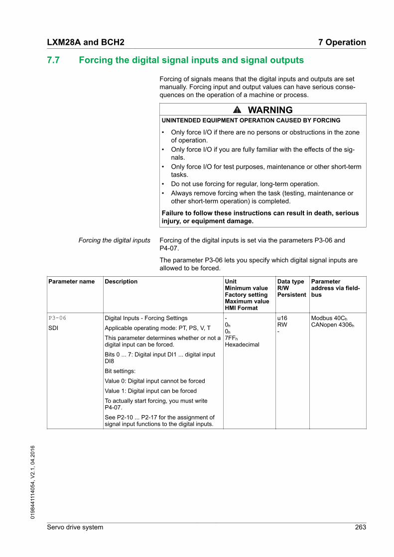
7.7 Forcing the digital signal inputs and signal outputs
Forcing of signals means that the digital inputs and outputs are setmanually. Forcing input and output values can have serious conse-quences on the operation of a machine or process.
WARNINGUNINTENDED EQUIPMENT OPERATION CAUSED BY FORCING
• Only force I/O if there are no persons or obstructions in the zoneof operation.
• Only force I/O if you are fully familiar with the effects of the sig-nals.
• Only force I/O for test purposes, maintenance or other short-termtasks.
• Do not use forcing for regular, long-term operation.• Always remove forcing when the task (testing, maintenance or
other short-term operation) is completed.
Failure to follow these instructions can result in death, seriousinjury, or equipment damage.
Forcing the digital inputs Forcing of the digital inputs is set via the parameters P3-06 andP4-07.
The parameter P3-06 lets you specify which digital signal inputs areallowed to be forced.
Parameter name Description UnitMinimum valueFactory settingMaximum valueHMI Format
Data typeR/WPersistent
Parameteraddress via field-bus
P3-06SDI
Digital Inputs - Forcing Settings
Applicable operating mode: PT, PS, V, T
This parameter determines whether or not adigital input can be forced.
Bits 0 ... 7: Digital input DI1 ... digital inputDI8
Bit settings:
Value 0: Digital input cannot be forced
Value 1: Digital input can be forced
To actually start forcing, you must writeP4-07.
See P2-10 ... P2-17 for the assignment ofsignal input functions to the digital inputs.
-0h 0h 7FFh Hexadecimal
u16RW-
Modbus 40Ch CANopen 4306h
LXM28A and BCH2 7 Operation
Servo drive system 263
0198
4411
1405
4, V
2.1,
04.
2016

Use parameter P4-07 to actually activate forcing of the digital signalinputs.
Parameter name Description UnitMinimum valueFactory settingMaximum valueHMI Format
Data typeR/WPersistent
Parameteraddress via field-bus
P4-07ITST
State of Digital Inputs / Activate Forcing
Applicable operating mode: PT, PS, V, T
A read access to this parameter indicatesthe state of the digital inputs in the form of abit pattern.
Example:
Read value 0x0011: Digital inputs 1 and 5are activated
By writing this parameter, you can changethe state of the inputs provided that the set-ting for the corresponding input in P3-06allows for forcing (value 1 for the bit corre-sponding to the input).
Example:
Write value 0x0011: Digital inputs 1 and 5are activated
Read value 0x0011: Digital inputs 1 and 5are activated
See P3-06 for permitting forcing of individ-ual digital inputs.
See P2-10 ... P2-17 for the assignment ofsignal input functions to the digital inputs.
-0h 0h FFh Hexadecimal
u16RW-
Modbus 50Eh CANopen 4407h
Forcing the digital outputs Forcing of the digital outputs is set via the parameters P4-27 andP4-28.
The parameter P4-27 lets you specify which digital signal outputs areallowed to be forced.
Parameter name Description UnitMinimum valueFactory settingMaximum valueHMI Format
Data typeR/WPersistent
Parameteraddress via field-bus
P4-27DO_FORCE_MASK
Digital Outputs - Forcing Settings
Applicable operating mode: PT, PS, V, T
This parameter determines whether or not adigital output can be forced.
Bits 0 ... 4: Digital output DO1 ... digital out-put DO5
Bit settings:
Value 0: Digital output cannot be forced
Value 1: Digital output can be forced
To actually start forcing, you must writeP4-28.
See P2-18 ... P2-22 for the assignment ofsignal output functions to the digital outputs.
-0h 0h 1Fh Hexadecimal
u16RW-
Modbus 536h CANopen 441Bh
7 Operation LXM28A and BCH2
264 Servo drive system
0198
4411
1405
4, V
2.1,
04.
2016

Use parameter P4-28 to actually activate forcing of the digital signaloutputs.
Parameter name Description UnitMinimum valueFactory settingMaximum valueHMI Format
Data typeR/WPersistent
Parameteraddress via field-bus
P4-28DO_FORCE_VALUE
State of Digital Outputs / Activate Forcing
Applicable operating mode: PT, PS, V, T
A read access to this parameter indicatesthe state of the digital outputs in the form ofa bit pattern.
Example:
Read value 0x0011: Digital outputs 1 and 5are activated
By writing this parameter, you can changethe state of the outputs provided that thesetting for the corresponding output inP4-27 allows for forcing (value 1 for the bitcorresponding to the output).
Example:
Write value 0x0011: Digital outputs 1 and 5are activated
Read value 0x0011: Digital outputs 1 and 5are activated
See P4-27 for permitting forcing of individ-ual digital outputs.
See P2-18 ... P2-22 for the assignment ofsignal output functions to the digital outputs.
-0h 0h 1Fh Hexadecimal
u16RW-
Modbus 538h CANopen 441Ch
LXM28A and BCH2 7 Operation
Servo drive system 265
0198
4411
1405
4, V
2.1,
04.
2016

7 Operation LXM28A and BCH2
266 Servo drive system
0198
4411
1405
4, V
2.1,
04.
2016

8 Examples
8.1 Wiring examples
PBePBiPA/+
PA/+
PC/-
TSR
L2
L1
~
CN
1
12
34
56
78
12
34
56
7 8
Encoder
M
U
V
W
CN4
CN9
CN2
D/A
CN3
A/D
+
+ GATE DRIVER
Control loop
CANopen,CANmotion
Interface
RS-485Modbus
Pha
se L
oss
Det
ectio
n
Reg
ener
atio
n ci
rcui
t
Protection Circuit
Internalbraking resistor
ServoMotor
Servo drive
Ext
erna
lbr
akin
g re
sist
orC
omm
onD
C b
usco
nnec
tion
DC bus
STO
A, B, Z Output
Analog MonitorOutput
Position Pulse
External Torque
External Speed
Digital Input
Digital Output
Rec
tifie
r circ
uit
Figure 140: Wiring example
LXM28A and BCH2 8 Examples
Servo drive system 267
0198
4411
1405
4, V
2.1,
04.
2016

8.2 Wiring example with Modicon M221 Logic Controller
Logic type 1 Wiring example with Modicon M221 Logic Controller (logic type 1).
V0+
V0-
7
41
9
11
43
39
37
35
36
V1-
COMI0
I1
Q9
Q8
V1+
Q2
Q1
Q3
Q0
+24Vdc
+24Vdc
+24Vdc
Servo Drive
Pulse
Pulse
Direction
Direction
6
DI1- (Enable)
DO1- (Ready)
M221
24V
24V
5V
5V
Figure 141: Wiring example with Modicon M221 and logic type 1
8 Examples LXM28A and BCH2
268 Servo drive system
0198
4411
1405
4, V
2.1,
04.
2016

Logic type 2 Wiring example with Modicon M221 Logic Controller (logic type 2).
V0+
V0-
7
41
9
11
43
39
37
35
36
V1-
COMI0
I1
Q9
Q8
V1+
Q2
Q1
Q3
Q0
+24Vdc
+24Vdc
Servo Drive
Pulse
Pulse
Direction
Direction
6
DI1- (Enable)
DO1- (Ready)
M22124V
24V
5V
5V
+24Vdc
Figure 142: Wiring example with Modicon M221 and logic type 2
LXM28A and BCH2 8 Examples
Servo drive system 269
0198
4411
1405
4, V
2.1,
04.
2016

8 Examples LXM28A and BCH2
270 Servo drive system
0198
4411
1405
4, V
2.1,
04.
2016

9 Diagnostics and troubleshooting
9.1 Status request/status indication
Information on the product status is provided by:
• Integrated HMI• Commissioning software LXM28 DTM Library• Fieldbus
The error memory also contains a history of the last 5 detected errors.
Meaning of an error An error is a discrepancy between a computed, measured or signaledvalue or condition and the specified or theoretically correct value orcondition detected by a monitoring function. An error triggers a transi-tion of the operating state.
Meaning of an alert An alert indicates a potential issue that was detected by a monitoringfunction. An alert does not trigger a transition of the operating state.
LXM28A and BCH2 9 Diagnostics and troubleshooting
Servo drive system 271
0198
4411
1405
4, V
2.1,
04.
2016

9.1.1 Fieldbus status LEDs
The fieldbus status LEDs visualize the status of the fieldbus.
S
M
Figure 143: Fieldbus status LEDs
The illustration below shows the fieldbus communication states.
1
2
3
4
5
6
7
8
1s
1s
1s0,2s
RUN ERR
Figure 144: Signals of the CAN bus status LEDs (Run=GN; Err=RD)
(1) NMT state PRE-OPERATIONAL(2) NMT state STOPPED(3) NMT state OPERATIONAL(4) Incorrect settings,
for example, invalid node address(5) Alert limit reached,
for example after 16 incorrect transmission attempts(6) Node Guarding(7) CAN is BUS-OFF,
for example after 32 incorrect transmission attempts.(8) Fieldbus communication without error message
9 Diagnostics and troubleshooting LXM28A and BCH2
272 Servo drive system
0198
4411
1405
4, V
2.1,
04.
2016

9.1.2 Error diagnostics via integrated HMI
The parameters P4-00 to P4-04 allow you to read the error memory.
Figure 145: Reading the error memory via the HMI
P4-00 Error number of the most recently detected error
... ...
P4-04 Error number of the oldest detected error
The parameter P0-47 allows you to read the last detected alert.
9.1.3 Diagnostics via the commissioning software
See the information provided with the commissioning software fordetails on how to display the device state via the commissioning soft-ware LXM28 DTM Library.
LXM28A and BCH2 9 Diagnostics and troubleshooting
Servo drive system 273
0198
4411
1405
4, V
2.1,
04.
2016
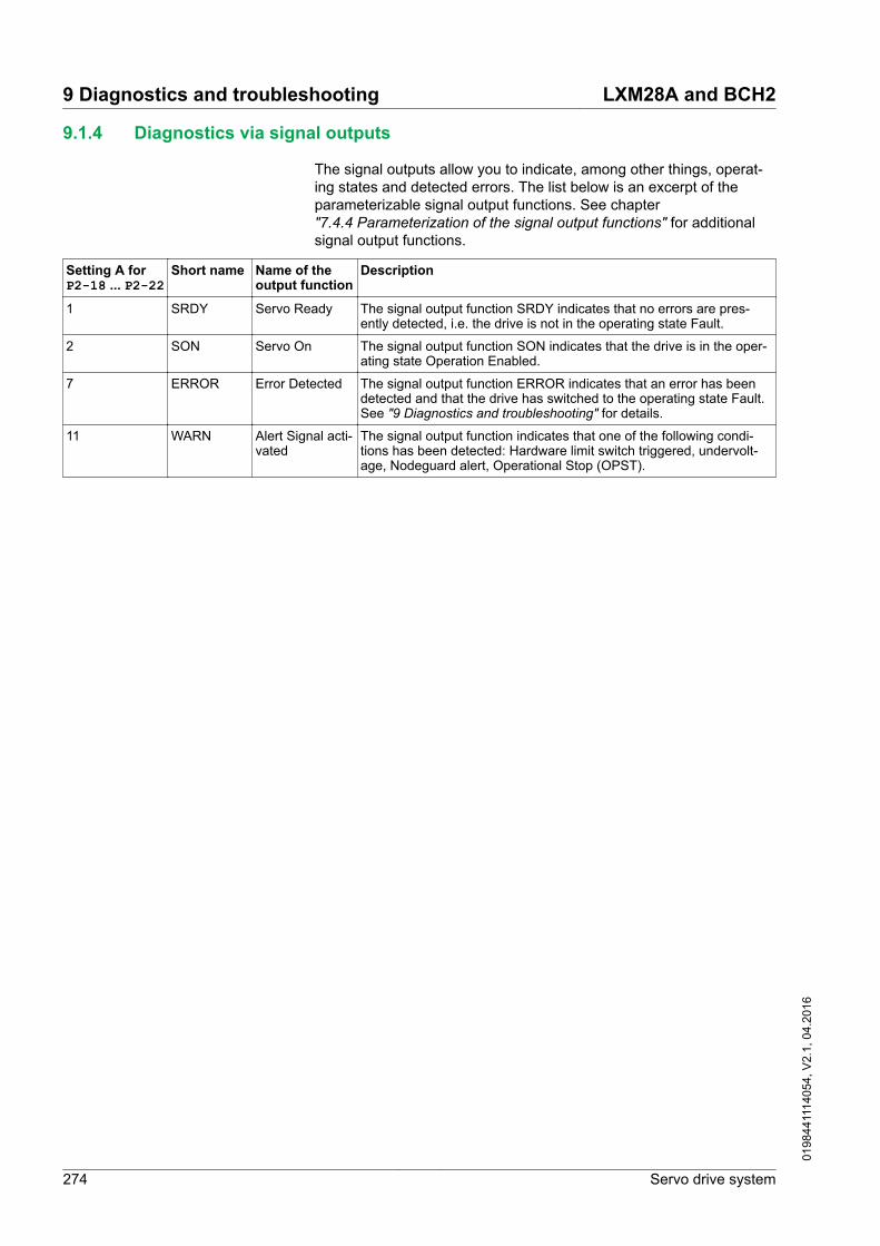
9.1.4 Diagnostics via signal outputs
The signal outputs allow you to indicate, among other things, operat-ing states and detected errors. The list below is an excerpt of theparameterizable signal output functions. See chapter"7.4.4 Parameterization of the signal output functions" for additionalsignal output functions.
Setting A forP2-18 ... P2-22
Short name Name of theoutput function
Description
1 SRDY Servo Ready The signal output function SRDY indicates that no errors are pres-ently detected, i.e. the drive is not in the operating state Fault.
2 SON Servo On The signal output function SON indicates that the drive is in the oper-ating state Operation Enabled.
7 ERROR Error Detected The signal output function ERROR indicates that an error has beendetected and that the drive has switched to the operating state Fault.See "9 Diagnostics and troubleshooting" for details.
11 WARN Alert Signal acti-vated
The signal output function indicates that one of the following condi-tions has been detected: Hardware limit switch triggered, undervolt-age, Nodeguard alert, Operational Stop (OPST).
9 Diagnostics and troubleshooting LXM28A and BCH2
274 Servo drive system
0198
4411
1405
4, V
2.1,
04.
2016

9.2 Alert codes
Number Description Cause RemedyAL014 Negative hardware limit switch
triggered- -
AL015 Positive hardware limit switchtriggered
- -
AL283 Positive software limit switchtriggered
- -
AL285 Negative software limit switchtriggered
- -
Wn023 Alert threshold reached: Motoroverload (foldback)
The foldback current of the motor hasdropped below the alert thresholdspecified via the parameter P1-28.
Verify correct settings of the parame-ter P1-28 for the foldback current ofthe motor.
Wn123 PDO packet too short - Verify correct PDO mapping.
Wn124 Data in PDO out of range - Verify that the minimum and maxi-mum limit values are not exceeded.
Wn127 R_PDO data cannot be writtenwhile the power stage is ena-bled
- -
Wn185 CANopen: A communicationerror was detected.
Wn283 Target value will cause move-ment to positive software limitswitch
- Verify correct target positions.
Wn285 Target value will cause move-ment to negative software limitswitch
- Verify correct target positions.
Wn380 Position deviation via signaloutput function MC_OK
After a movement has been success-fully completed, MC_OK was active.Then TPOS became inactive whichcaused MC_OK to become inactiveas well.
If you want this condition to cause adetected error instead of an alert, setthe parameter P1-48 accordingly.
Wn700 Safety function Safe TorqueOff (STO) triggered while thepower stage was disabled
The safety function STO has beentriggered or the signal for the safetyfunction STO is not properly connec-ted. If this condition is detected whilethe power stage is enabled, the drivedetects an error. If this condition isdetected while the power stage is dis-abled, the drive detects an alert.
Check whether the safety functionSTO was triggered intentionally. Ifnot, verify correct connection of thesignal of the safety function STO.
Wn701 Alert threshold reached: Driveoverload (foldback)
The foldback current of the drive hasdropped below the alert thresholdspecified via the parameter P1-24.
Verify correct settings of the parame-ter P1-24 for the foldback current ofthe drive.
Wn702 The DC bus voltage has drop-ped below the alert threshold.
Power supply loss, poor power sup-ply.
Verify correct mains supply. Verifythat the undervoltage limit is set cor-rectly via the parameter P4-24.
Wn703 Alert threshold reached:Power stage overtemperature
Ambient temperature is too high, fanis inoperative, dust.
Verify correct operation of the fan.Improve the heat dissipation in thecontrol cabinet. Remove pollution andverify that dust cannot get into thecontrol cabinet or into the drive.
LXM28A and BCH2 9 Diagnostics and troubleshooting
Servo drive system 275
0198
4411
1405
4, V
2.1,
04.
2016

Number Description Cause RemedyWn704 Alert threshold reached: Motor
overtemperatureThe motor temperature is excessivelyhigh.
Verify correct settings of the parame-ters for temperature monitoring. Verifyproper ventilation and heat dissipa-tion of the motor. Clean off pollutantssuch as dust. Verify that the motor isevenly mounted to the flange plate.Increase the size of the flange plateto which the motor is mounted toimprove heat dissipation. Verify thatthe motor is properly sized for theapplication.
Wn707 Alert threshold reached: Driveovertemperature (controller)
Ambient temperature is too high, fanis inoperative, dust.
Verify correct operation of the fan.Improve the heat dissipation in thecontrol cabinet. Remove pollution andverify that dust cannot get into thecontrol cabinet or into the drive.
Wn709 PLL not synchronized - -
Wn713 Positive hardware limit switchand negative hardware limittriggered
- -
Wn716 Positive software limit switchand negative software limittriggered
- -
Wn728 Alert: Missing mains supply,undervoltage mains supply
At least one mains phase is missing.Mains voltage is out of range. Mainsfrequency is out of range.
Verify correct connection of mainssupply. Verify that the values of themains power supply network complywith the technical data.
Wn729 Modbus: Node Guarding errordetected
Incorrect Modbus connection, incor-rect data from Modbus master.
Verify correct Modbus connection.Verify correct operation of Modbusmaster.
Wn730 Alert threshold reached: Brak-ing resistor overload
The permissible braking resistorpower has been exceeded.
Verify correct rating of the brakingresistor used. Verify your application.
Wn731 Encoder error detected - -
Wn732 Alert threshold reached: Pro-cessing time too long
- -
Wn734 Alert threshold reached: Driveovertemperature (IPM)
Ambient temperature is too high, fanis inoperative, dust.
Verify correct operation of the fan.Improve the heat dissipation in thecontrol cabinet. Remove pollution andverify that dust cannot get into thecontrol cabinet or into the drive.
Wn736 PDO packet too long - Verify correct PDO mapping.
Wn737 The parameters have beenreset to the factory settings,but not yet been saved to thenon volatile memory.
- Use parameter P2-08 = 11 to savethe parameters reset to the factorysettings to the non volatile memoryand restart the drive.
Wn738 No target values received viathe fieldbus
No target values have been receivedvia the fieldbus three times in succes-sion.
Verify that target values are transmit-ted via the fieldbus. Verify that thefieldbus has exclusive access.
Wn739 Temperature value for monitor-ing function not available
- -
Wn742 Motor type has changed. The type of motor connected is differ-ent from the previously connectedtype of motor.
Reset the drive to the factory settings.
9 Diagnostics and troubleshooting LXM28A and BCH2
276 Servo drive system
0198
4411
1405
4, V
2.1,
04.
2016

9.3 Error codes
Error number Short description Cause RemedyAL001 Power stage overcurrent An overcurrent has been detected
at the power stage which may becaused by a short circuit or byincorrect settings of the currentloop parameters. This conditionmay occur up to three times insuccession. After the third time, atime delay of one minute mustpass before the power stage canbe enabled again.
Verify correct connection of themotor. Verify correct settings ofthe parameters for the currentloop.
AL002 DC bus overvoltage The DC bus voltage exceeded themaximum value.
Verify your application. Reducethe external load, the motor veloc-ity or the deceleration. Use anappropriately rated braking resis-tor, if necessary.
AL003 DC bus undervoltage Power supply loss, poor powersupply.
Verify correct mains supply. Verifythat the undervoltage limitation isset correctly via the parameterP4-24.
AL005 Braking resistor overload The braking resistor has been onfor such a long period of time thatits overload capability has beenexceeded.
Verify your application. Reducethe external load, the motor veloc-ity or the deceleration. Use a brak-ing resistor with a higher rating, ifnecessary.
AL006 Motor overload (foldback) The foldback current of the motorhas dropped below the valuespecified via the parameter P1-27.
Verify correct settings for theparameter P1-27.
AL007 Actual motor velocity toohigh.
The actual motor velocity excee-ded the velocity limitation by morethan 20% (P1-55). The analoginput signal is not stable.
Verify that the velocity limitationset via the parameter P1-55matches the requirements of theapplication. Verify that the valuesfor the tuning parameters are suit-able. Verify that the frequency ofthe analog input signal is stableusing a signal detector. Use a filterfunction.
AL008 Frequency of referencevalue signal is too high
The frequency of the pulse signal(A/B, Pulse/Direction, CW/CCW)exceeds the specified range.Received pulses may be lost.
Adapt the output pulse frequencyof the external source to fit theinput specification of the drive.Adapt the gear ratios to the appli-cation requirements (parametersP1-44, P1-45, P2-60, P2-61 andP2-62).
AL009 Position deviation too high(following error)
The position deviation has excee-ded the maximum permissibleposition deviation specified via theparameter P2-35 and the drivehas detected a following error.
Verify your application. Reducethe external load. Increase thepermissible position deviation viathe parameter P2-35. Reduce themotor velocity via the parametersP1-09 ? P1-11 or the analog inputV_REF. Increase the torque limita-tion via the parameters P1-12 ?P1-14 or the analog input T_REF.
AL013 The input to which the sig-nal input function OPST isassigned has been activa-ted.
- Identify the cause which has trig-gered the signal input functionOPST. Remove the cause. If yourapplication does not require thesignal input function OPST, disa-ble this signal input function.
LXM28A and BCH2 9 Diagnostics and troubleshooting
Servo drive system 277
0198
4411
1405
4, V
2.1,
04.
2016

Error number Short description Cause RemedyAL016 Power stage overtempera-
tureAmbient temperature is too high,fan is inoperative, dust.
Verify correct operation of the fan.Improve the heat dissipation in thecontrol cabinet. Remove pollutionand verify that dust cannot get intothe control cabinet or into thedrive.
AL017 Error detected in non-vola-tile memory
The drive was reset to the factorysettings via parameter P2-08.
Use parameter P2-08 = 11 to savethe parameters reset to the factorysettings to the non volatile mem-ory and restart the drive.
Contact technical support.
AL018 Encoder simulation fre-quency exceeded 4 MHz
The computed equivalent encoderoutput frequency exceeds themaximum limit of 4 MHz for thissignal.
Reduce the resolution of theencoder simulation via the param-eter P1-46 or reduce the maxi-mum velocity.
AL020 Modbus: Node Guardingerror detected
Incorrect Modbus connection,incorrect data from Modbus mas-ter.
Verify correct Modbus connection.Verify correct operation of Modbusmaster.
AL022 Missing mains supply,undervoltage mains supply
At least one mains phase is miss-ing. Mains voltage is out of range.Mains frequency is out of range.
Verify correct connection of mainssupply. Verify that the values ofthe mains power supply networkcomply with the technical data.
AL025 Not possible to read dataof electronic motor name-plate
Incorrect or missing motor data.Motor without electronic motornameplate has been connected.
Verify that the drive and the con-nected motor are a permissibleproduct combination. Verify cor-rect connection of the encoder.Contact Technical Support orreplace the motor.
AL026 Error detected in communi-cation with motor encoder
Communication with the encoderwas not initialized correctly.
Verify correct connection of theencoder. Contact Technical Sup-port or replace the motor.
AL030 Motor torque too high foran excessive period oftime
The motor torque has exceededthe value specified via the param-eter P1-57 for a period of timeexceeding the value specified viathe parameter P1-58.
Verify your application. Verify thatno movements are made up to amechanical stop (for example, uselimit switches). Verify that the val-ues for the parameters P1-57 andP1-58 are suitable.
AL180 CANopen: Heartbeat errordetected
The bus cycle time of the CAN-open master is higher than theprogrammed heartbeat or nodeguard time. The connectionbetween the CANopen masterand the drive is lost.
Verify correct CANopen connec-tion. Check the CANopen master.Verify correct CANopen configura-tion, increase the Heartbeat orNode Guarding time.
AL3E1 Drive is not synchronouswith master cycle
Operating mode has been activa-ted but drive is not synchronizedto external synchronization signal.
Verify correct CANopen connec-tion. After having started the syn-chronization mechanism, wait for120 cycles before activating theoperating mode.
AL401 Fieldbus: Communicationerror detected
While the power stage was ena-bled, a command was receivedrequesting a different communica-tion state.
Verify that the master does not tryto change the communicationstate while the power stage of thedrive is enabled.
9 Diagnostics and troubleshooting LXM28A and BCH2
278 Servo drive system
0198
4411
1405
4, V
2.1,
04.
2016

Error number Short description Cause RemedyAL501 Safety function Safe Tor-
que Off (STO) triggeredThe safety function STO has beentriggered or the signal for thesafety function STO is not prop-erly connected. If this condition isdetected while the power stage isenabled, the drive detects anerror. If this condition is detectedwhile the power stage is disabled,the drive detects an alert.
Check whether the safety functionSTO was triggered intentionally. Ifnot, verify correct connection ofthe signal of the safety functionSTO.
AL502 System error detected(FPGA)
- Contact technical support.
AL503 System error detected(non volatile memory)
- Contact technical support.
AL504 System error detected(non volatile memory)
- Contact technical support.
AL505 DC bus voltage measure-ment
An error was detected in the cir-cuit that measures the DC busvoltage.
Perform a Fault Reset. Restart thedrive. If the error persists, contactTechnical Support.
AL507 System error detected (NVaccess)
- Contact technical support.
AL508 Drive overload (foldback) The foldback current of the drivehas dropped below the valuespecified via the parameter P1-23.
Verify correct settings for theparameter P1-23.
AL514 Motor overtemperature The motor temperature is exces-sively high.
Verify correct settings of theparameters P8-59 and P8-60 fortemperature monitoring. Verifyproper ventilation and heat dissi-pation of the motor. Clean off pol-lutants such as dust. Verify thatthe motor is evenly mounted tothe flange plate. Increase the sizeof the flange plate to which themotor is mounted to improve heatdissipation. Verify that the motor isproperly sized for the application.
AL517 Encoder overvoltage orovercurrent
The current supplied by the drivefor the 5 V encoder supply hasexceeded the limit. This conditionmay occur up to three times insuccession. After the third time, atime delay of one second mustpass before the power stage canbe enabled again.
Verify correct connection of theencoder (short circuits). Verify thecurrent consumption of theencoder.
AL520 Target position rejected A target position was rejectedbecause it would have caused themotor to exceed the maximumvelocity.
Verify that target positions do notlead to excessive motor velocities.
AL522 System error detected(CAN power supply)
The internal supply voltage for theCAN bus is not correct.
Contact technical support.
AL523 System error detected (selftest)
The self test has detected anerror.
Contact technical support.
AL525 Reserved Reserved Reserved
AL526 Reserved Reserved Reserved
AL527 System error detected(Watchdog)
The Watchdog function has detec-ted a system error.
Restart the drive. If the error per-sists, contact Technical Support.
LXM28A and BCH2 9 Diagnostics and troubleshooting
Servo drive system 279
0198
4411
1405
4, V
2.1,
04.
2016

Error number Short description Cause RemedyAL528 Drive overtemperature
(IPM)Ambient temperature is too high,fan is inoperative, dust.
Verify correct operation of the fan.Improve the heat dissipation in thecontrol cabinet. Remove pollutionand verify that dust cannot get intothe control cabinet or into thedrive.
AL529 Drive overtemperature(controller)
Ambient temperature is too high,fan is inoperative, dust.
Verify correct operation of the fan.Improve the heat dissipation in thecontrol cabinet. Remove pollutionand verify that dust cannot get intothe control cabinet or into thedrive.
AL532 Calculated offsets for cur-rent sensors out of range
The calculated offsets for the cur-rent sensors are out of range.
Perform a Fault Reset. Restart thedrive. If the error persists, contactTechnical Support.
AL533 Reserved Reserved Reserved
AL534 Pulse signal missing One of the pulse signals is notconnected.
Verify correct connection of thepulse inputs.
AL535 System error detected(FPGA does not matchfirmware)
The firmware version is not suita-ble for the drive.
Update the firmware of the drive.Contact technical support.
AL539 Motor phase missing One of the motor phases is notconnected.
Verify correct connection of themotor phases. Contact technicalsupport.
AL547 Motor blocked The motor was blocked mechani-cally, for example, by a mechani-cal stop or by the load.
Remove condition causing themechanical blocking. Verify yourapplication.
AL553 No connection betweenmaster and drive
- Connect master and drive.
AL554 Target position rejected A target position was rejectedbecause it would have caused themotor to exceed the maximumacceleration/deceleration.
Verify that target positions do notlead to excessive acceleration/deceleration.
AL555 Velocity deviation too high The deviation between actualvelocity and reference velocity hasexceeded the maximum velocitydeviation specified via the param-eter P2-34.
Verify your application. Verify thatthe values for the tuning parame-ters are suitable. Increase thevalue for the maximum velocitydeviation in the parameter P2-34.
AL557 No target values receivedvia the fieldbus
No target values have beenreceived via the fieldbus threetimes in succession.
Perform a Fault Reset. Verify thattarget values are transmitted viathe fieldbus.
AL558 System error detected - Contact technical support.
AL560 Controller supply off - Power on the controller supply.
AL561 Temperature sensor inop-erative
- Restart the drive. If the error per-sists, contact Technical Support.
AL563 Commutation error detec-ted
Motor phases have been inter-changed.
Verify correct connection of themotor phases.
AL564 Position deviation via sig-nal output function MC_OK
After a movement has been suc-cessfully completed, MC_OK wasactive. Then TPOS became inac-tive which caused MC_OK tobecome inactive as well.
Use the signal input functionFAULT_RESET to perform a FaultReset and set the parameterP0-01 to 0. If you want this condi-tion to cause an alert instead of adetected error, set the parameterP1-48 accordingly.
AL567 System error detected(encoder)
- Contact technical support.
9 Diagnostics and troubleshooting LXM28A and BCH2
280 Servo drive system
0198
4411
1405
4, V
2.1,
04.
2016

Error number Short description Cause RemedyAL568 Braking resistor overload The permissible braking resistor
power has been exceeded.Verify correct rating of the brakingresistor used. Verify your applica-tion.
AL569 Configuration not correctlytransferred via Modbus
- Verify correct connection. Verifythat configuration file and driveare compatible.
AL570 Overcurrent detected atone of the digital outputs
- Verify correct wiring of the digitaloutputs. Verify there are no shortcircuits.
AL572 Position deviation too high(following error)
The position deviation has excee-ded the maximum permissibleposition deviation specified via theparameter P2-35 and the drivehas detected a following error.
Verify your application. Reducethe external load. Increase thepermissible position deviation viathe parameter P2-35. Reduce themotor velocity via the parametersP1-09 ? P1-11 or the analog inputV_REF. Increase the torque limita-tion via the parameters P1-12 ?P1-14 or the analog input T_REF.
AL585 CANopen device in statebus-off
Too many error frames have beendetected. CANopen devices havedifferent baud rates.
Verify correct baud rates. VerifyCANopen bus installation.
AL588 Reserved Reserved Reserved
AL595 Impermissible combinationof drive and motor
- Use an approved drive/motorcombination.
LXM28A and BCH2 9 Diagnostics and troubleshooting
Servo drive system 281
0198
4411
1405
4, V
2.1,
04.
2016

9 Diagnostics and troubleshooting LXM28A and BCH2
282 Servo drive system
0198
4411
1405
4, V
2.1,
04.
2016

10 Parameters
This chapter provides an overview of the parameters which can beused for operating the product.
Unsuitable settings or unsuitable data may trigger unintended move-ments, trigger signals, damage parts and disable monitoring functions.Some settings do not become active until after a restart.
WARNINGUNINTENDED EQUIPMENT OPERATION
• Only start the system if there are no persons or obstructions inthe zone of operation.
• Do not operate the drive system with unknown settings or data.• Never modify a parameter unless you fully understand the param-
eter and all effects of the modification.• After modifications to settings, restart the drive and verify the
saved data or settings.• When commissioning the product, carefully run tests for all oper-
ating states and potential error situations.• Verify the functions after replacing the product and also after
making modifications to the settings or data.
Failure to follow these instructions can result in death, seriousinjury, or equipment damage.
10.1 Representation of the parameters
Parameter name The parameter name uniquely identifies a parameter.
Unit The unit of the value.
LXM28A and BCH2 10 Parameters
Servo drive system 283
0198
4411
1405
4, V
2.1,
04.
2016

10.2 List of parameters
Parameter name Description UnitMinimum valueFactory settingMaximum valueHMI Format
Data typeR/WPersistent
Parameteraddress via field-bus
P0-00VER
Firmware Version
Applicable operating mode: PT, PS, V, T
-0h 0h FFFFh Hexadecimal
u16RO-
Modbus 100h CANopen 4000h
P0-01ALE
Error code of detected error
Applicable operating mode: PT, PS, V, T
This parameter contains the error number ofthe most recently detected error.
See chapter "9.3 Error codes" for a list ofthe detected errors.
-0h 0h FFFFh Hexadecimal
u16RW-
Modbus 102h CANopen 4001h
P0-02STS
Drive Status Displayed by HMI
Applicable operating mode: PT, PS, V, T
This parameter selects the type of statusinformation to be displayed on the HMI.
Example: If the setting is 7, the HMI dis-plays the speed of rotation of the motor.
For details see chapter"6.2.3 Status information via the HMI".
-00123Decimal
u16RWper.
Modbus 104h CANopen 4002h
10 Parameters LXM28A and BCH2
284 Servo drive system
0198
4411
1405
4, V
2.1,
04.
2016

Parameter name Description UnitMinimum valueFactory settingMaximum valueHMI Format
Data typeR/WPersistent
Parameteraddress via field-bus
P0-03MON
Function of Analog Outputs
Applicable operating mode: PT, PS, V, T
This parameter specifies the functions of theanalog outputs.
X: CH1Y: CH2not used
XY: (X: MON1; Y: MON2)
0: Actual velocity (+/-8 V correspond tomaximum velocity)
1: Actual torque (+/-8 V correspond to maxi-mum torque)
2: Reference value in kilopulses per second(+8 V correspond to 4.5 Mpps)
3: Target velocity (+/-8 V correspond tomaximum target velocity)
4: Target torque (+/-8 V correspond to maxi-mum target torque)
5: DC bus voltage (+/-8 V correspond to 450V)
6: Reserved
7: Reserved
See P1-04 and P1-05 for setting a voltagepercentage (scaling).
Example:
P0-03 = 01: Voltage value at analog outputindicates the actual velocity.
Velocity = (maximum velocity x V1 / 8) xP1-04 / 100 if the output voltage value ofMON2 is V1.
-0h 0h 77h Hexadecimal
u16RWper.
Modbus 106h CANopen 4003h
P0-08TSON
Operating Hour Meter in Seconds
Applicable operating mode: PT, PS, V, T
s0-4294967295Decimal
u32RO-
Modbus 110h CANopen 4008h
LXM28A and BCH2 10 Parameters
Servo drive system 285
0198
4411
1405
4, V
2.1,
04.
2016

Parameter name Description UnitMinimum valueFactory settingMaximum valueHMI Format
Data typeR/WPersistent
Parameteraddress via field-bus
P0-09CM1
Status Value 1
Applicable operating mode: PT, PS, V, T
This parameter is used to provide the valueof one of the status indications in P0-02.The value of this parameter is determinedvia P0-17.
Examples:
If the status of the drive is read via the HMIand if P0-02 is set to 23, VAR-1 is displayedfor approximately two seconds by the HMI,followed by the value of this parameter.
If the setting of P0-17 is 3, reading thisparameter displays the actual position inpulses.
For reading the status via Modbus, read two16-bit data stored in the addresses of0012H and 0013H to generate 32-bit data.
(0013H : 0012H) = (high byte : low byte)
--2147483647-2147483647Decimal
s32RO-
Modbus 112h CANopen 4009h
P0-10CM2
Status Value 2
Applicable operating mode: PT, PS, V, T
This parameter is used to provide the valueof one of the status indications in P0-02.The value of this parameter is determinedvia P0-18.
See P0-09 for details.
--2147483647-2147483647Decimal
s32RO-
Modbus 114h CANopen 400Ah
P0-11CM3
Status Value 3
Applicable operating mode: PT, PS, V, T
This parameter is used to provide the valueof one of the status indications in P0-02.The value of this parameter is determinedvia P0-19.
See P0-09 for details.
--2147483647-2147483647Decimal
s32RO-
Modbus 116h CANopen 400Bh
P0-12CM4
Status Value 4
Applicable operating mode: PT, PS, V, T
This parameter is used to provide the valueof one of the status indications in P0-02.The value of this parameter is determinedvia P0-20.
See P0-09 for details.
--2147483647-2147483647Decimal
s32RO-
Modbus 118h CANopen 400Ch
P0-13CM5
Status Value 5
Applicable operating mode: PT, PS, V, T
This parameter is used to provide the valueof one of the status indications in P0-02.The value of this parameter is determinedvia P0-21.
See P0-09 for details.
--2147483647-2147483647Decimal
s32RO-
Modbus 11Ah CANopen 400Dh
10 Parameters LXM28A and BCH2
286 Servo drive system
0198
4411
1405
4, V
2.1,
04.
2016

Parameter name Description UnitMinimum valueFactory settingMaximum valueHMI Format
Data typeR/WPersistent
Parameteraddress via field-bus
P0-17CMA1
Indicate status value 1
Applicable operating mode: PT, PS, V, T
This parameter is used to select a drive sta-tus provided in P0-02. The selected statusis indicated via P0-09.
Example:
If the setting of P0-17 is 7, reading P0-09returns the speed of rotation of the motor inmin-1.
-00123Decimal
u16RWper.
Modbus 122h CANopen 4011h
P0-18CMA2
Indicate status value 2
Applicable operating mode: PT, PS, V, T
This parameter is used to select a drive sta-tus provided in P0-02. The selected statusis indicated via P0-10. See P0-17 fordetails.
-00123Decimal
u16RWper.
Modbus 124h CANopen 4012h
P0-19CMA3
Indicate status value 3
Applicable operating mode: PT, PS, V, T
This parameter is used to select a drive sta-tus provided in P0-02. The selected statusis indicated via P0-11. See P0-17 for details.
-00123Decimal
u16RWper.
Modbus 126h CANopen 4013h
P0-20CMA4
Indicate status value 4
Applicable operating mode: PT, PS, V, T
This parameter is used to select a drive sta-tus provided in P0-02. The selected statusis indicated via P0-12. See P0-17 fordetails.
-00123Decimal
u16RWper.
Modbus 128h CANopen 4014h
P0-21CMA5
Indicate status value 5
Applicable operating mode: PT, PS, V, T
This parameter is used to select a drive sta-tus provided in P0-02. The selected statusis indicated via P0-13. See P0-17 fordetails.
-00123Decimal
u16RWper.
Modbus 12Ah CANopen 4015h
P0-25MAP1
Parameter Mapping 1
Applicable operating mode: PT, PS, V, T
The parameters from P0-25 ... P0-32 areused to read and write the values of param-eters with non-consecutive communicationaddresses. You can set P0-35 ... P0-42 asthe required read and write mapping param-eter numbers. When P0-25 ... P0-32 areread, the read or write values are equivalentto the values of the parameters specified viaP0-35 ... P0-42, and vice versa. See P0-35for details.
-0h 0h FFFFFFFFh Hexadecimal
u32RW-
Modbus 132h CANopen 4019h
P0-26MAP2
Parameter Mapping 2
Applicable operating mode: PT, PS, V, T
See P0-25 and P0-36 for details.
-0h 0h FFFFFFFFh Hexadecimal
u32RW-
Modbus 134h CANopen 401Ah
LXM28A and BCH2 10 Parameters
Servo drive system 287
0198
4411
1405
4, V
2.1,
04.
2016

Parameter name Description UnitMinimum valueFactory settingMaximum valueHMI Format
Data typeR/WPersistent
Parameteraddress via field-bus
P0-27MAP3
Parameter Mapping 3
Applicable operating mode: PT, PS, V, T
See P0-25 and P0-37 for details.
-0h 0h FFFFFFFFh Hexadecimal
u32RW-
Modbus 136h CANopen 401Bh
P0-28MAP4
Parameter Mapping 4
Applicable operating mode: PT, PS, V, T
See P0-25 and P0-38 for details.
-0h 0h FFFFFFFFh Hexadecimal
u32RW-
Modbus 138h CANopen 401Ch
P0-29MAP5
Parameter Mapping 5
Applicable operating mode: PT, PS, V, T
See P0-25 and P0-39 for details.
-0h 0h FFFFFFFFh Hexadecimal
u32RW-
Modbus 13Ah CANopen 401Dh
P0-30MAP6
Parameter Mapping 6
Applicable operating mode: PT, PS, V, T
See P0-25 and P0-40 for details.
-0h 0h FFFFFFFFh Hexadecimal
u32RW-
Modbus 13Ch CANopen 401Eh
P0-31MAP7
Parameter Mapping 7
Applicable operating mode: PT, PS, V, T
See P0-25 and P0-41 for details.
-0h 0h FFFFFFFFh Hexadecimal
u32RW-
Modbus 13Eh CANopen 401Fh
P0-32MAP8
Parameter Mapping 8
Applicable operating mode: PT, PS, V, T
See P0-25 and P0-42 for details.
-0h 0h FFFFFFFFh Hexadecimal
u32RW-
Modbus 140h CANopen 4020h
10 Parameters LXM28A and BCH2
288 Servo drive system
0198
4411
1405
4, V
2.1,
04.
2016

Parameter name Description UnitMinimum valueFactory settingMaximum valueHMI Format
Data typeR/WPersistent
Parameteraddress via field-bus
P0-35MAPA1
Block Data Read/Write P0-35…P0-42 1
Applicable operating mode: PT, PS, V, T
The parameters P0-35 ... P0-42 specify therequired read and write parameter numbersfor P0-25 ... P0-32. They read and write thevalues of the parameters whose communi-cation addresses are not consecutive.
The read / write parameter can be a single32-bit parameter or two 16-bit parameters.
ABnot used
A: Parameter group code in hexadecimalformat
B: Parameter number in hexadecimal format
Example:
If you want to read and write the value ofP1-44 (32-bit parameter) via P0-25, setP0-35 to 012C012Ch.
If you want to read and write the values ofP2-02 (16-bit parameter) and P2-04 (16-bitparameter) via P0-25, set P0-35 to02040202h.
-0h 0h FFFFFFFFh Hexadecimal
u32RWper.
Modbus 146h CANopen 4023h
P0-36MAPA2
Block Data Read/Write P0-35…P0-42 2
Applicable operating mode: PT, PS, V, T
See P0-35 for details.
-0h 0h FFFFFFFFh Hexadecimal
u32RWper.
Modbus 148h CANopen 4024h
P0-37MAPA3
Block Data Read/Write P0-35…P0-42 3
Applicable operating mode: PT, PS, V, T
See P0-35 for details.
-0h 0h FFFFFFFFh Hexadecimal
u32RWper.
Modbus 14Ah CANopen 4025h
P0-38MAPA4
Block Data Read/Write P0-35…P0-42 4
Applicable operating mode: PT, PS, V, T
See P0-35 for details.
-0h 0h FFFFFFFFh Hexadecimal
u32RWper.
Modbus 14Ch CANopen 4026h
P0-39MAPA5
Block Data Read/Write P0-35…P0-42 5
Applicable operating mode: PT, PS, V, T
See P0-35 for details.
-0h 0h FFFFFFFFh Hexadecimal
u32RWper.
Modbus 14Eh CANopen 4027h
P0-40MAPA6
Block Data Read/Write P0-35…P0-42 6
Applicable operating mode: PT, PS, V, T
See P0-35 for details.
-0h 0h FFFFFFFFh Hexadecimal
u32RWper.
Modbus 150h CANopen 4028h
LXM28A and BCH2 10 Parameters
Servo drive system 289
0198
4411
1405
4, V
2.1,
04.
2016

Parameter name Description UnitMinimum valueFactory settingMaximum valueHMI Format
Data typeR/WPersistent
Parameteraddress via field-bus
P0-41MAPA7
Block Data Read/Write P0-35…P0-42 7
Applicable operating mode: PT, PS, V, T
See P0-35 for details.
-0h 0h FFFFFFFFh Hexadecimal
u32RWper.
Modbus 152h CANopen 4029h
P0-42MAPA8
Block Data Read/Write P0-35…P0-42 8
Applicable operating mode: PT, PS, V, T
See P0-35 for details.
-0h 0h FFFFFFFFh Hexadecimal
u32RWper.
Modbus 154h CANopen 402Ah
P0-46SVSTS
State of Signal Output Functions
Applicable operating mode: PT, PS, V, T
This parameter is used to indicate the stateof the signal output function of the drive inhexadecimal format. If the function isassigned to a digital output, it would repre-sent the state of the output given no forcingon the output.
Bit 0: SRDY (Servo ready)
Bit 1: SON (Servo On)
Bit 2: ZSPD (Zero speed)
Bit 3: TSPD (Speed reached)
Bit 4: TPOS (Movement completed)
Bit 5: TQL (Torque Limit Reached)
Bit 6: ERR (Error Detected)
Bit 7: BRKR (Holding brake control)
Bit 8: HOMED_OK (Homing completed)
Bit 9: OLW (Motor Overload Alert)
Bit 10: WARN (indicates that one of the fol-lowing conditions has been detected: Hard-ware limit switch triggered, undervoltage,Nodeguard alert, Operational Stop (OPST))
Bits 11 ... 15: Reserved
The parameter can also be read via thefieldbus.
-0h 0h FFFFh Hexadecimal
u16RO-
Modbus 15Ch CANopen 402Eh
P0-47LAST_WRN
Number of Last Alert
Applicable operating mode: PT, PS, V, T
This parameter contains the number of thelast detected alert. After a Fault Reset, thenumber is cleared.
-0h 0h FFFFh Hexadecimal
u16RO-
Modbus 15Eh CANopen 402Fh
10 Parameters LXM28A and BCH2
290 Servo drive system
0198
4411
1405
4, V
2.1,
04.
2016

Parameter name Description UnitMinimum valueFactory settingMaximum valueHMI Format
Data typeR/WPersistent
Parameteraddress via field-bus
P1-00PTT
Reference Value Signal - Pulse Settings
Applicable operating mode: PT
A
B
C
D
not used
This parameter is used to configure the ref-erence value signals for the operating modePT.
A: Type of reference value signals
B: Signal frequency
C: Input polarity
D: Source of reference value signals
Setting can only be changed if power stageis disabled.
-0h 2h 1132h Hexadecimal
u16RWper.
Modbus 200h CANopen 4100h
LXM28A and BCH2 10 Parameters
Servo drive system 291
0198
4411
1405
4, V
2.1,
04.
2016

Parameter name Description UnitMinimum valueFactory settingMaximum valueHMI Format
Data typeR/WPersistent
Parameteraddress via field-bus
P1-01CTL
Operating Mode and Direction of Rotation
Applicable operating mode: PT, PS, V, T
A
not used
C
D
not used
A: Operating modeSee chapter"7.3.1 Setting the operating mode".
C: Direction of movementSee chapter"6.5.1 Verifying the direction of movement".
D: Signal input functions and signal outputfunctions after operating mode switching
Value 0: The assignments of the signal inputfunctions and the signal output functions(P2-10 ... P2-22) remain identical for thenew operating mode.
Value 1: The assignments of the signal inputfunctions and the signal output functions(P2-10 ... P2-22) are set to the default pre-sets of the new operating mode. See chap-ters"7.4.1 Default presets of the signal inputs"and"7.4.3 Default presets of the signal outputs".
Changed settings become active the nexttime the product is powered on.
-0h Bh 110Bh Hexadecimal
u16RWper.
Modbus 202h CANopen 4101h
10 Parameters LXM28A and BCH2
292 Servo drive system
0198
4411
1405
4, V
2.1,
04.
2016

Parameter name Description UnitMinimum valueFactory settingMaximum valueHMI Format
Data typeR/WPersistent
Parameteraddress via field-bus
P1-02PSTL
Velocity and Torque Limitations Activation/Deactivation
Applicable operating mode: PT, PS, V, T
This parameter activates/deactivates veloc-ity limitation and torque limitation.Velocity limitation and torque limitation canalso be activated via the signal input func-tions SPDLM and TRQLM.The signal input functions SPD0 and SPD1are used to select velocity values set viaP1-09 to P1-11. The signal input functionsTCM0 and TCM1 are used to select torquevalues set via P1-12 to P1-14.
ABnot used
A: Velocity limitation0: Deactivate1: Activate (in operating mode T)
P1-09(1)P1-10(2)P1-11(3)
Vref
SPD0SPD1
(0)
Speed LimitCommand
B: Torque limitation0: Deactivate1: Activate (operating modes PT, PS and V)
P1-12(1)P1-13(2)P1-14(3)
Tref
TCM0TCM1
(0)
Torque LimitCommand
-0h 0h 11h Hexadecimal
u16RWper.
Modbus 204h CANopen 4102h
LXM28A and BCH2 10 Parameters
Servo drive system 293
0198
4411
1405
4, V
2.1,
04.
2016

Parameter name Description UnitMinimum valueFactory settingMaximum valueHMI Format
Data typeR/WPersistent
Parameteraddress via field-bus
P1-03AOUT
Polarity of Analog Outputs / Polarity ofPulse Outputs
Applicable operating mode: PT, PS, V, T
ABnot used
This parameter is used to specify the polar-ity of analog outputs MON1 and MON2 andthe polarity of pulse outputs.
A: Polarity of analog outputs MON1 andMON2
0: MON1(+), MON2(+)
1: MON1(+), MON2(-)
2: MON1(-), MON2(+)
3: MON1(-), MON2(-)
B: Polarity of pulse outputs
0: Not inverted
1: Inverted
-0h 0h 13h Hexadecimal
u16RWper.
Modbus 206h CANopen 4103h
P1-04MON1
Scaling Factor Analog Output 1
Applicable operating mode: PT, PS, V, T
%1100100Decimal
u16RWper.
Modbus 208h CANopen 4104h
P1-05MON2
Scaling Factor Analog Output 2
Applicable operating mode: PT, PS, V, T
%1100100Decimal
u16RWper.
Modbus 20Ah CANopen 4105h
P1-09SP1
Target Velocity/Velocity Limitation 1
Applicable operating mode: V, T
Target velocity 1
In the operating mode V, this parameterspecifies the first target velocity.
Velocity limitation 1
In the operating mode T, this parameterspecifies the first velocity limitation.
0.1rpm-600001000060000Decimal
s32RWper.
Modbus 212h CANopen 4109h
P1-10SP2
Target Velocity/Velocity Limitation 2
Applicable operating mode: V, T
Target velocity 2
In the operating mode V, this parameterspecifies the second target velocity.
Velocity limitation 2
In the operating mode T, this parameterspecifies the second velocity limitation.
0.1rpm-600002000060000Decimal
s32RWper.
Modbus 214h CANopen 410Ah
10 Parameters LXM28A and BCH2
294 Servo drive system
0198
4411
1405
4, V
2.1,
04.
2016

Parameter name Description UnitMinimum valueFactory settingMaximum valueHMI Format
Data typeR/WPersistent
Parameteraddress via field-bus
P1-11SP3
Target Velocity/Velocity Limitation 3
Applicable operating mode: V, T
Target velocity 3
In the operating mode V, this parameterspecifies the third target velocity.
Velocity limitation 3
In the operating mode T, this parameterspecifies the third velocity limitation.
0.1rpm-600003000060000Decimal
s32RWper.
Modbus 216h CANopen 410Bh
P1-12TQ1
Target Torque/Torque Limitation 1
Applicable operating mode: PT, PS, V, T
Target torque 1 in percent of nominal cur-rent
In the operating mode T, this parameterspecifies the first target torque.
Torque limitation 1 in percent of nominalcurrent
In the operating modes PT, PS and V, thisparameter specifies the first torque limita-tion.
The signal output function TQL is activatedif the torque reaches the torque limitationsset via the parameters P1-12 ... P1-14 or viaan analog input.
%-300100300Decimal
s16RWper.
Modbus 218h CANopen 410Ch
P1-13TQ2
Target Torque/Torque Limitation 2
Applicable operating mode: PT, PS, V, T
Target torque 2 in percent of nominal cur-rent
In the operating mode T, this parameterspecifies the second target torque.
Torque limitation 2 in percent of nominalcurrent
In the operating modes PT, PS and V, thisparameter specifies the second torque limi-tation.
The signal output function TQL is activatedif the torque reaches the torque limitationsset via the parameters P1-12 ... P1-14 or viaan analog input.
%-300100300Decimal
s16RWper.
Modbus 21Ah CANopen 410Dh
LXM28A and BCH2 10 Parameters
Servo drive system 295
0198
4411
1405
4, V
2.1,
04.
2016

Parameter name Description UnitMinimum valueFactory settingMaximum valueHMI Format
Data typeR/WPersistent
Parameteraddress via field-bus
P1-14TQ3
Target Torque/Torque Limitation 3
Applicable operating mode: PT, PS, V, T
Target torque 3 in percent of nominal cur-rent
In the operating mode T, this parameterspecifies the third target torque.
Torque limitation 3 in percent of nominalcurrent
In the operating modes PT, PS and V, thisparameter specifies the third torque limita-tion.
The signal output function TQL is activatedif the torque reaches the torque limitationsset via the parameters P1-12 ... P1-14 or viaan analog input.
%-300100300Decimal
s16RWper.
Modbus 21Ch CANopen 410Eh
P1-15LINELOSSMODE
Mains Phase Monitoring - Response toMissing Mains Phase
Applicable operating mode: PT, PS, V, T
This parameter specifies the response ofthe drive if the mains phase monitoringfunction detects an error.
Value 0: Detected error if power stage isenabled or disabledValue 1: Detected error if power stage isenabled, alert if power stage is disabledValue 2: Alert if power stage is enabled ordisabled
-002Decimal
u16RWper.
Modbus 21Eh CANopen 410Fh
P1-16LINELOSSRE-COVER
Mains Phase Monitoring - Fault Reset
Applicable operating mode: PT, PS, V, T
This parameter specifies the type of FaultReset after a detected mains phase errorhas been removed.
Value 0: No automatic Fault ResetValue 1: Automatic Fault Reset
-001Decimal
u16RWper.
Modbus 220h CANopen 4110h
P1-17LINELOSSTYPE
Mains Phase Monitoring - Type
Applicable operating mode: PT, PS, V, T
This parameter specifies the type of mainsphase monitoring
Value 0: No mains phase monitoringValue 1: Mains phase monitoring single-phase connectionValue 2: Mains phase monitoring three-phase connection
-002Decimal
u16RWper.
Modbus 222h CANopen 4111h
P1-18 ReservedP1-19DISTIME
Active Disable - Delay Time Power Stage
Applicable operating mode: PT, PS, V, T
This parameter specifies the delay timebetween standstill of the motor and disa-bling the power stage.
ms006500Decimal
u16RWper.
Modbus 226h CANopen 4113h
10 Parameters LXM28A and BCH2
296 Servo drive system
0198
4411
1405
4, V
2.1,
04.
2016

Parameter name Description UnitMinimum valueFactory settingMaximum valueHMI Format
Data typeR/WPersistent
Parameteraddress via field-bus
P1-20ESTOPILIM
Current Limit During Quick Stop
Applicable operating mode: PT, PS, V
This parameter specifies the maximum cur-rent during a Quick Stop (expressed as fac-tor of P1-78).
0.001110001000Decimal
s16RWper.
Modbus 228h CANopen 4114h
P1-21FOLD
Status of Foldback Current Drive
Applicable operating mode: PT, PS, V, T
This parameter indicates whether the fold-back current limit is greater than or lessthan the maximum current of the drive (seeP1-78).
Value 0: Foldback current limit greater thanP1-78Value 1: Foldback current limit is less thanP1-78
-0-1Decimal
u16RO-
Modbus 22Ah CANopen 4115h
P1-22IFOLD
Foldback Current Limit - Drive
Applicable operating mode: PT, PS, V, T
Drive foldback current limit
0.01A0-30000Decimal
u32RO-
Modbus 22Ch CANopen 4116h
P1-23IFOLDFTHRESH
Current Monitoring Drive - Detected ErrorThreshold Foldback Current
Applicable operating mode: PT, PS, V, T
This parameter specifies the threshold valueused by the drive current monitoring func-tion to detect a drive foldback current error.
0.01A0-30000Decimal
u32RWper.
Modbus 22Eh CANopen 4117h
P1-24IFOLDWTHRESH
Current Monitoring Drive - Alert ThresholdFoldback Current
Applicable operating mode: PT, PS, V, T
This parameter specifies the threshold valueused by the drive current monitoring func-tion to trigger a drive foldback current alert.
0.01A0-30000Decimal
u32RWper.
Modbus 230h CANopen 4118h
P1-25 ReservedP1-26MIFOLD
Foldback Current Limit - Motor
Applicable operating mode: PT, PS, V, T
Motor foldback current limit
0.01A0-30000Decimal
u32RO-
Modbus 234h CANopen 411Ah
P1-27MIFOLDFTHRESH
Motor Current Monitoring - Detected ErrorThreshold Foldback Current
Applicable operating mode: PT, PS, V, T
This parameter specifies the threshold valueused by the motor current monitoring func-tion to detect a motor foldback current error.
0.01A0-30000Decimal
u32RWper.
Modbus 236h CANopen 411Bh
P1-28MIFOLDWTHRESH
Motor Current Monitoring - Alert ThresholdFoldback Current
Applicable operating mode: PT, PS, V, T
This parameter specifies the threshold valueused by the motor current monitoring func-tion to trigger a motor foldback current alert.
0.01A0-30000Decimal
u32RWper.
Modbus 238h CANopen 411Ch
LXM28A and BCH2 10 Parameters
Servo drive system 297
0198
4411
1405
4, V
2.1,
04.
2016

Parameter name Description UnitMinimum valueFactory settingMaximum valueHMI Format
Data typeR/WPersistent
Parameteraddress via field-bus
P1-29OVTHRESH
DC Bus Overvoltage Monitoring - Threshold
Applicable operating mode: PT, PS, V, T
This parameter specifies the threshold valueused by the DC bus overvoltage monitoringfunction.
V---Decimal
u16RO-
Modbus 23Ah CANopen 411Dh
P1-30RAMAXERRCNT
Commutation Monitoring - Maximum Coun-ter Value
Applicable operating mode: PT, PS, V, T
ms000Decimal
u16RW-
Modbus 23Ch CANopen 411Eh
P1-32LSTP
Stop Method
Applicable operating mode: PT, PS, V
This parameter specifies how the motor isstopped if the power stage is to be disabled(includes signal input function OPST) or ifan error is detected.
Value 0h: Deceleration ramp
Value 10h: Coast to stop
Value 20h: Deceleration ramp to velocityP1-38, then coast to stop (actual velocitymust be less than the value of P1-38 for 50ms before coasting to stop starts)
In the operating mode Torque (T), the decel-eration ramp is not used. Instead, the cur-rent is set to zero.
Depending on the event that triggered thestop, the following deceleration ramps areused:- Signal input function STOP: P5-20- Transmission error detected: P5-21- Position overflow: P5-22- Triggering of negative software limitswitch: P5-23- Triggering of positive software limit switch:P5-24- Triggering of negative hardware limitswitch: P5-25- Triggering of positive hardware limitswitch: P5-26- Any other event: P1-68
The delay time between standstill of themotor and disabling the power stage is setvia P1-19.
-0h 0h 20h Hexadecimal
u16RWper.
Modbus 240h CANopen 4120h
10 Parameters LXM28A and BCH2
298 Servo drive system
0198
4411
1405
4, V
2.1,
04.
2016

Parameter name Description UnitMinimum valueFactory settingMaximum valueHMI Format
Data typeR/WPersistent
Parameteraddress via field-bus
P1-34TACC
Acceleration Period
Applicable operating mode: PT, V
The acceleration period is the time in milli-seconds required to accelerate from motorstandstill to 6000 min-1.
For operating mode V, this parameter speci-fies the acceleration. If the target velocity issupplied as an analog signal, the maximumvalue of this parameter is automatically limi-ted to 20000.
For operating mode PT, this parameterspecifies an acceleration limitation for thepulses at the PTI interface.
ms63065500Decimal
u16RWper.
Modbus 244h CANopen 4122h
P1-35TDEC
Deceleration Period
Applicable operating mode: PT, V
The deceleration period is the time in milli-seconds required to decelerate from6000 min-1 to motor standstill.
For operating mode V, this parameter speci-fies the deceleration. If the target velocity issupplied as an analog signal, the maximumvalue of this parameter is automatically limi-ted to 20000.
For operating mode PT, this parameterspecifies a deceleration limitation for thepulses at the PTI interface.
ms63065500Decimal
u16RWper.
Modbus 246h CANopen 4123h
P1-37LMJR
Ratio of Load Inertia to Motor Inertia
Applicable operating mode: PT, PS, V, T
This parameter specifies the ratio of loadinertia to motor inertia (J_load / J_motor).
J_load: Total moment of inertia of externalmechanical load
J_motor: Moment of inertia of motor
0.101020000Decimal
u32RWper.
Modbus 24Ah CANopen 4125h
P1-38ZSPD
Signal Output Function ZSPD / Signal InputFunction ZCLAMP - Velocity
Applicable operating mode: PT, PS, V, T
This parameter specifies the velocity for thesignal output function ZSPD. The signal out-put function ZSPD indicates that the velocityof the motor is less than the velocity valueset via this parameter.
This parameter specifies the velocity for thesignal input function ZCLAMP. The signalinput function ZCLAMP stops the motor.The velocity of the motor must be below thevelocity value set via this parameter.
0.1rpm01002000Decimal
s32RWper.
Modbus 24Ch CANopen 4126h
LXM28A and BCH2 10 Parameters
Servo drive system 299
0198
4411
1405
4, V
2.1,
04.
2016

Parameter name Description UnitMinimum valueFactory settingMaximum valueHMI Format
Data typeR/WPersistent
Parameteraddress via field-bus
P1-39SSPD
Signal Output Function TSPD - Velocity
Applicable operating mode: PT, PS, V, T
This parameter specifies the velocity for thesignal output function TSPD. The signal out-put function TSPD indicates that the velocityof the motor is greater than the velocityvalue set via this parameter.
rpm030005000Decimal
u32RWper.
Modbus 24Eh CANopen 4127h
P1-40VCM
Velocity Target Value and Velocity Limitation10 V
Applicable operating mode: PT, PS, V, T
In the operating mode V, this parameterspecifies the target velocity that corre-sponds to the maximum input voltage of 10V.
In the operating mode T, this parameterspecifies the velocity limitation that corre-sponds to the maximum input voltage of 10V.
Example: If the value of this parameter is3000 in the operating mode V and if theinput voltage is 10 V, the target velocity is3000 min-1.
rpm0-10001Decimal
s32RWper.
Modbus 250h CANopen 4128h
P1-41TCM
Torque Target Value and Torque Limitation10 V
Applicable operating mode: PT, PS, V, T
In the operating mode T, this parameterspecifies the target torque that correspondsto the maximum input voltage of 10 V.
In the operating modes PT, PS and V, thisparameter specifies the torque limitationthat corresponds to the maximum input volt-age of 10 V.
Example: If the value of this parameter is100 in the operating mode T and if the inputvoltage is 10 V, the target torque is 100 % ofthe nominal torque.
Setting can only be changed if power stageis disabled.
%01001000Decimal
u16RWper.
Modbus 252h CANopen 4129h
P1-42MBT1
ON Delay Time of Holding Brake
Applicable operating mode: PT, PS, V, T
This parameter specifies the time betweenenabling the power stage and activation ofthe signal output function BRKR.
ms001000Decimal
u16RWper.
Modbus 254h CANopen 412Ah
P1-44GR1
Electronic Gear Ratio - Numerator 1
Applicable operating mode: PT, PS
This parameter is used to set the numeratorof the gear ratio. The denominator of thegear ratio is set via P1-45.
In the operating mode PS, the value of thisparameter can only be changed when thepower stage is disabled.
-1128536870911Decimal
u32RWper.
Modbus 258h CANopen 412Ch
10 Parameters LXM28A and BCH2
300 Servo drive system
0198
4411
1405
4, V
2.1,
04.
2016

Parameter name Description UnitMinimum valueFactory settingMaximum valueHMI Format
Data typeR/WPersistent
Parameteraddress via field-bus
P1-45GR2
Electronic Gear Ratio - Denominator
Applicable operating mode: PT, PS
This parameter is used to set the denomina-tor of the gear ratio. The numerator of thegear ratio is set via P1-44.
Setting can only be changed if power stageis disabled.
-1102147483647Decimal
u32RWper.
Modbus 25Ah CANopen 412Dh
P1-46ENCOUTRES
Encoder Simulation Resolution
Applicable operating mode: PT, PS, V, T
This parameter is used to set the resolutionof the encoder simulation via the digital out-put DO6 (OCZ).
Setting can only be changed if power stageis disabled.
LPR-2048-Decimal
s32RWper.
Modbus 25Ch CANopen 412Eh
P1-47SPOK
Signal Output Function SP_OK - Velocity
Applicable operating mode: V
This parameter specifies the velocity devia-tion window for the signal output functionSP_OK. The signal output function SP_OKindicates that actual velocity is within thevelocity deviation window.
rpm010300Decimal
u32RWper.
Modbus 25Eh CANopen 412Fh
P1-48MCOK
Signal Output Function MC_OK - Settings
Applicable operating mode: PS
This parameter specifies the behavior of thesignal output function MC_OK after it hasbeen activated. The signal output functionMC_OK indicates that both the signal outputfunctions CMD_OK and TPOS have beenactivated. In addition, you can specifywhether a detected position deviation is totrigger a detected error.
ABnot used
A: Behavior of MC_OK after deactivation ofTPOSValue 0: When TPOS is deactivated,MC_OK is deactivated.Value 1: When TPOS is deactivated,MC_OK remains activated.
B: Response to detected position deviationvia TPOS if A is set to 0Value 0: No responseValue 1: Detected alertValue 2: Detected error
-0h 0h 21h Hexadecimal
u16RWper.
Modbus 260h CANopen 4130h
LXM28A and BCH2 10 Parameters
Servo drive system 301
0198
4411
1405
4, V
2.1,
04.
2016

Parameter name Description UnitMinimum valueFactory settingMaximum valueHMI Format
Data typeR/WPersistent
Parameteraddress via field-bus
P1-52REGENRES
Braking Resistor - Resistance
Applicable operating mode: PT, PS, V, T
This parameter is used to set the resistanceof the braking resistor.
Value -1: No braking resistor
Ohm-1-32767Decimal
s16RWper.
Modbus 268h CANopen 4134h
P1-53REGENPOW
Braking Resistor - Power
Applicable operating mode: PT, PS, V, T
This parameter is used to set the power ofthe braking resistor.
Value -1: No braking resistor
W-1-32767Decimal
s16RWper.
Modbus 26Ah CANopen 4135h
P1-54PER
Signal Output Function TPOS - TriggerValue
Applicable operating mode: PT, PS
This parameter specifies the position devia-tion value used to activate the signal outputfunction TPOS.
Operating mode PT: The signal output func-tion TPOS indicates that the position devia-tion is within the tolerance set via thisparameter.
Operating mode PS: The signal output func-tion TPOS indicates that the position devia-tion at the target position is within the toler-ance set via this parameter.
PUU0128001280000Decimal
u32RWper.
Modbus 26Ch CANopen 4136h
P1-55VLIM
Maximum Velocity - User-Defined
Applicable operating mode: PT, PS, V, T
This parameter specifies the maximumvelocity. Default setting: nominal velocity.
Setting can only be changed if power stageis disabled.
rpm10-6000Decimal
u32RWper.
Modbus 26Eh CANopen 4137h
P1-57CRSHA
Torque Monitoring - Torque Value
Applicable operating mode: PT, PS, V, T
This parameter is used to configure the tor-que monitoring function. The torque moni-toring function detects an error (AL030) ifthe torque value set via this parameter isexceeded for a period of time set via P1-58.
%00300Decimal
u16RWper.
Modbus 272h CANopen 4139h
P1-58CRSHT
Torque Monitoring - Time Value
Applicable operating mode: PT, PS, V, T
This parameter is used to configure the tor-que monitoring function. The torque moni-toring function detects an error (AL030) ifthe torque value set via P1-57 is exceededfor a period of time set via this parameter.
ms111000Decimal
u16RWper.
Modbus 274h CANopen 413Ah
10 Parameters LXM28A and BCH2
302 Servo drive system
0198
4411
1405
4, V
2.1,
04.
2016

Parameter name Description UnitMinimum valueFactory settingMaximum valueHMI Format
Data typeR/WPersistent
Parameteraddress via field-bus
P1-59MFLT
S Curve Filter for Operating Mode Velocity
Applicable operating mode: V
This parameter specifies the moving aver-age time in [us] for the S curve filter in theoperating mode Velocity. The value of thisparameter must be a multiple of 125. Thisfilter changes a linear acceleration into an Scurve.
Setting can only be changed if power stageis disabled.
us00255875Decimal
u32RWper.
Modbus 276h CANopen 413Bh
P1-60RUNAWAYT-THRESH
Commutation Monitoring - Time Threshold
Applicable operating mode: PT, PS, V, T
ms003000Decimal
u16RWper.
Modbus 278h CANopen 413Ch
P1-61RUNAWAYV-THRESH
Commutation Monitoring - Velocity Thresh-old
Applicable operating mode: PT, PS, V, T
0.1rpm060060000Decimal
u32RWper.
Modbus 27Ah CANopen 413Dh
P1-62THERMODE
Motor Overtemperature Monitoring -Response
Applicable operating mode: PT, PS, V, T
This parameter specifies the response ofthe drive if the temperature monitoring func-tion detects motor overtemperature.
Value 0: Disable power stage immediatelyValue 3: Ignore overtemperatureValue 4: AlertValue 5: Alert first, then detected error ifcondition persists after P1-63
-005Decimal
u16RWper.
Modbus 27Ch CANopen 413Eh
P1-63THERMTIME
Motor Overtemperature Monitoring - DelayTime
Applicable operating mode: PT, PS, V, T
This parameter specifies the delay timebetween the detection of motor overtemper-ature and the transition to the operatingstate Fault (see P1-62).
s030300Decimal
u16RWper.
Modbus 27Eh CANopen 413Fh
P1-64UVMODE
Undervoltage Monitoring - Response
Applicable operating mode: PT, PS, V, T
This parameter specifies the response ofthe drive if the undervoltage monitoringfunction detects undervoltage.
Value 0: Detected errorValue 1: Alert (if power stage is enabled)Value 2: Alert first, then detected error ifcondition persists after P1-67 (if powerstage is enabled)Value 3: Detected error (if power stage isenabled)
-003Decimal
u16RWper.
Modbus 280h CANopen 4140h
P1-65 Reserved
LXM28A and BCH2 10 Parameters
Servo drive system 303
0198
4411
1405
4, V
2.1,
04.
2016

Parameter name Description UnitMinimum valueFactory settingMaximum valueHMI Format
Data typeR/WPersistent
Parameteraddress via field-bus
P1-66MFOLD
Status of Foldback Current Motor
Applicable operating mode: PT, PS, V, T
This parameter indicates whether the fold-back current limit is greater than or lessthan the maximum current of the motor (seeP1-78).
Value 0: Foldback current limit greater thanP1-78Value 1: Foldback current limit is less thanP1-78
-0-1Decimal
u16RO-
Modbus 284h CANopen 4142h
P1-67UVTIME
Undervoltage Monitoring - Delay Time
Applicable operating mode: PT, PS, V, T
This parameter specifies the delay timebetween the detection of an undervoltagecondition (displayed as "u")and theresponse of the drive to this condition asspecified in P1-64.
s030300Decimal
u16RWper.
Modbus 286h CANopen 4143h
P1-68DECSTOP
Active Disable - Deceleration Ramp
Applicable operating mode: PT, PS, V
This parameter specifies the decelerationramp for a power stage Disable request,see P1-32.
ms620065500Decimal
u16RWper.
Modbus 288h CANopen 4144h
P1-69DECSTOPTIME
Disable - Deceleration Time
Applicable operating mode: PT, PS, V
This parameter specifies the decelerationramp for a power stage Disable request,see P1-32. If the value of this parameter isnot 0, this parameter overrides P1-68.
Setting can only be changed if power stageis disabled.
ms006500Decimal
u16RWper.
Modbus 28Ah CANopen 4145h
P1-70IMAXHALT
Signal Input Function HALT - Maximum Cur-rent
Applicable operating mode: T
This parameter specifies the maximum cur-rent for the signal input function Halt. Themaximum value for this parameter is thevalue of P1-79.
0.01A-0-Decimal
u32RWper.
Modbus 28Ch CANopen 4146h
P1-71REGENMAXON-TIME
Braking Resistor - Maximum Time in Brak-ing
Applicable operating mode: PT, PS, V, T
This parameter specifies the maximum timein braking for the braking resistor. The maxi-mum time in braking is the maximum periodof time during which the braking resistormay be activated.
ms1040100Decimal
u16RWper.
Modbus 28Eh CANopen 4147h
10 Parameters LXM28A and BCH2
304 Servo drive system
0198
4411
1405
4, V
2.1,
04.
2016

Parameter name Description UnitMinimum valueFactory settingMaximum valueHMI Format
Data typeR/WPersistent
Parameteraddress via field-bus
P1-72REGENFLTMODE
Braking Resistor Overload Monitoring -Response
Applicable operating mode: PT, PS, V, T
This parameter specifies the response ofthe drive if the braking resistor overloadmonitoring function detects braking resistoroverload.
Value 0: AlertValue 1: Detected error
-001Decimal
u16RWper.
Modbus 290h CANopen 4148h
P1-78ILIM
User-Defined Maximum Current
Applicable operating mode: PT, PS, V, T
This parameter is specifies a user-definedmaximum current for the drive. The maxi-mum value of this parameter is the value ofP1-79.
0.01A---Decimal
u32RWper.
Modbus 29Ch CANopen 414Eh
P1-79IMAX
Maximum Current
Applicable operating mode: PT, PS, V, T
This parameter indicates the maximum cur-rent for a drive / motor combination.
0.01A---Decimal
u32RO-
Modbus 29Eh CANopen 414Fh
P1-80DIPEAK
Maximum Peak Current
Applicable operating mode: PT, PS, V, T
This parameter indicates the maximumpeak current of the drive.
0.01A---Decimal
u32RO-
Modbus 2A0h CANopen 4150h
P1-81DICONT
Nominal Current
Applicable operating mode: PT, PS, V, T
This parameter indicates the nominal cur-rent of the drive.
0.01A---Decimal
u32RO-
Modbus 2A2h CANopen 4151h
P1-82CAN-OPEN_VEL_LIMIT
Velocity limitation for CANopen operatingmode Profile Torque
Applicable operating mode: Fieldbus mode
Value 0: Limitation via analog inputValue 1: Limitation via P1-09Value 2: Limitation via P1-10Value 3: Limitation via P1-11
-003Decimal
u16RWper.
Modbus 2A4h CANopen 4152h
P1-83OPMODE_CHANGE_MODE
Change of operating mode during move-ment
Applicable operating mode: PT, PS, V, T
Value 0: With motor standstillValue 1: Without motor standstill
-001Decimal
u16RWper.
Modbus 2A6h CANopen 4153h
P1-84CFG_MOTOR
Configured motor type
Applicable operating mode: PT, PS, V, T
-0-2147483647Decimal
u32ROper.
Modbus 2A8h CANopen 4154h
LXM28A and BCH2 10 Parameters
Servo drive system 305
0198
4411
1405
4, V
2.1,
04.
2016

Parameter name Description UnitMinimum valueFactory settingMaximum valueHMI Format
Data typeR/WPersistent
Parameteraddress via field-bus
P2-01PPR
Gain Switching - Rate for Position Loop
Applicable operating mode: PT, PS
This parameter specifies the gain switchingrate for the position loop. The gain switchingfunction is configured via this parameter andparameters P2-05, P2-27 and P2-29.
%10100500Decimal
u16RWper.
Modbus 302h CANopen 4201h
P2-05SPR
Gain Switching - Rate for Velocity Loop
Applicable operating mode: PT, PS, V, T
This parameter specifies the gain switchingrate for the velocity loop. The gain switchingfunction is configured via this parameter andparameters P2-01, P2-27 and P2-29.
%10100500Decimal
u16RWper.
Modbus 30Ah CANopen 4205h
P2-08PCTL
Factory Reset / Save Parameters
Applicable operating mode: PT, PS, V, T
This parameter provides the following func-tions:- Reset the parameters to the factory set-tings- Save the current parameter values
Changes to this parameter are only possiblewhen the power stage is disabled. The fac-tory settings do not become effective untilafter you have powered the drive off and onagain.
Value 10: Reset the parameter values to thefactory settings
Value 11: Save the parameter values
-00406Decimal
u16RW-
Modbus 310h CANopen 4208h
P2-09DRT
Debounce Time - Inputs
Applicable operating mode: PT, PS, V, T
This parameter specifies the debounce timefor the digital inputs DI1 ... DI5 and DI8. SeeP2-24 for the debounce time for the fast dig-ital inputs DI6 and DI7.
ms0220Decimal
u16RWper.
Modbus 312h CANopen 4209h
10 Parameters LXM28A and BCH2
306 Servo drive system
0198
4411
1405
4, V
2.1,
04.
2016

Parameter name Description UnitMinimum valueFactory settingMaximum valueHMI Format
Data typeR/WPersistent
Parameteraddress via field-bus
P2-10DITF1
Signal Input Function for DI1
Applicable operating mode: PT, PS, V, T
The parameters P2-10 ... P2-17 are used toassign signal input functions to the digitalinputs DI1 ... DI8 and to configure the typeof digital input (normally closed, normallyopen).
A: Signal input functions:
For the values see chapter"7.4 Setting the digital signal inputs and sig-nal outputs".
B: Type:
0: Normally closed (contact b)
1: Normally open (contact a)
Example: If the setting of P2-10 is 101, thesignal input function assigned to digital input1 is SON (0x01) and the type of contact is anormally open contact.
The drive must be restarted after the param-eters have been changed.
Forcing of digital inputs is configured viaP3-06 and activated via P4-07.
Setting can only be changed if power stageis disabled.
-0h 100h 146h Hexadecimal
u16RWper.
Modbus 314h CANopen 420Ah
P2-11DITF2
Signal Input Function for DI2
Applicable operating mode: PT, PS, V, T
See P2-10 for details.
Setting can only be changed if power stageis disabled.
-0h 100h 146h Hexadecimal
u16RWper.
Modbus 316h CANopen 420Bh
P2-12DITF3
Signal Input Function for DI3
Applicable operating mode: PT, PS, V, T
See P2-10 for details.
Setting can only be changed if power stageis disabled.
-0h 100h 146h Hexadecimal
u16RWper.
Modbus 318h CANopen 420Ch
P2-13DITF4
Signal Input Function for DI4
Applicable operating mode: PT, PS, V, T
See P2-10 for details.
Setting can only be changed if power stageis disabled.
-0h 100h 146h Hexadecimal
u16RWper.
Modbus 31Ah CANopen 420Dh
P2-14DITF5
Signal Input Function for DI5
Applicable operating mode: PT, PS, V, T
See P2-10 for details.
Setting can only be changed if power stageis disabled.
-0h 24h 146h Hexadecimal
u16RWper.
Modbus 31Ch CANopen 420Eh
LXM28A and BCH2 10 Parameters
Servo drive system 307
0198
4411
1405
4, V
2.1,
04.
2016

Parameter name Description UnitMinimum valueFactory settingMaximum valueHMI Format
Data typeR/WPersistent
Parameteraddress via field-bus
P2-15DITF6
Signal Input Function for DI6
Applicable operating mode: PT, PS, V, T
See P2-10 for details.
Setting can only be changed if power stageis disabled.
-0h 22h 146h Hexadecimal
u16RWper.
Modbus 31Eh CANopen 420Fh
P2-16DITF7
Signal Input Function for DI7
Applicable operating mode: PT, PS, V, T
See P2-10 for details.
Setting can only be changed if power stageis disabled.
-0h 23h 146h Hexadecimal
u16RWper.
Modbus 320h CANopen 4210h
P2-17DITF8
Signal Input Function for DI8
Applicable operating mode: PT, PS, V, T
See P2-10 for details.
Setting can only be changed if power stageis disabled.
-0h 21h 146h Hexadecimal
u16RWper.
Modbus 322h CANopen 4211h
P2-18DOTF1
Signal Output Function for DO1
Applicable operating mode: PT, PS, V, T
The parameters P2-18 ... P2-22 are used toassign signal output functions to the digitaloutputs DO1 ... DO5 and to configure thetype of digital output (normally closed, nor-mally open).
ABnot used
A: Signal output functions:
For the values see chapter"7.4 Setting the digital signal inputs and sig-nal outputs".
B: Type:
0: Normally closed (contact b)
1: Normally open (contact a)
Example: If the setting of P2-18 is 101, thesignal output function assigned to digitaloutput 1 is SRDY (0x01) and the type ofcontact is a normally open contact.
-0h 101h 13Fh Hexadecimal
u16RWper.
Modbus 324h CANopen 4212h
P2-19DOTF2
Signal Output Function for DO2
Applicable operating mode: PT, PS, V, T
See P2-18 for details.
-0h 100h 13Fh Hexadecimal
u16RWper.
Modbus 326h CANopen 4213h
P2-20DOTF3
Signal Output Function for DO3
Applicable operating mode: PT, PS, V, T
See P2-18 for details.
-0h 100h 13Fh Hexadecimal
u16RWper.
Modbus 328h CANopen 4214h
10 Parameters LXM28A and BCH2
308 Servo drive system
0198
4411
1405
4, V
2.1,
04.
2016

Parameter name Description UnitMinimum valueFactory settingMaximum valueHMI Format
Data typeR/WPersistent
Parameteraddress via field-bus
P2-21DOTF4
Signal Output Function for DO4
Applicable operating mode: PT, PS, V, T
See P2-18 for details.
-0h 100h 13Fh Hexadecimal
u16RWper.
Modbus 32Ah CANopen 4215h
P2-22DOTF5
Signal Output Function for DO5
Applicable operating mode: PT, PS, V, T
See P2-18 for details.
-0h 7h 13Fh Hexadecimal
u16RWper.
Modbus 32Ch CANopen 4216h
P2-23DOTF6
Signal Output Function for DO6(OCZ)
Applicable operating mode: PT, PS, V, T
Only the signal output function ESIM can beassigned to the digital output DO6 (OCZ).Use P2-18 ... P22 for assigning other signaloutput functions to the other digital outputsDO1 ... DO5.See P2-18 for details.
-0h 40h 13Fh Hexadecimal
u16RWper.
Modbus 32Eh CANopen 4217h
P2-24FDRT
Debounce Time - Fast Inputs
Applicable operating mode: PT, PS, V, T
This parameter specifies the debounce timefor the digital inputs DI6 and DI7. See P2-09for the debounce time for the digital inputsDI1 ... DI5 and DI8.
us050100Decimal
u16RWper.
Modbus 330h CANopen 4218h
P2-27GCC
Gain Switching - Conditions and Type
Applicable operating mode: PT, PS, V, T
This parameter specifies the conditions forand the type of gain switching. The gainswitching function is configured via thisparameter and parameters P2-01, P2-05and P2-29.
ABnot used
A: Conditions for gain switching:0: Disabled1: Signal input function GAINUP is active2: In operating modes PT and PS, the posi-tion deviation is greater than the value ofP2-293: Pulse frequency is greater than the valueof P2-294: Velocity is greater than the value of P2-295: Signal input function GAINUP is notactive6: In operating modes PT and PS, the posi-tion deviation is less than the value of P2-297: Pulse frequency is less than the value ofP2-298: Velocity is less than the value of P2-29
-0h 0h 18h Hexadecimal
u16RWper.
Modbus 336h CANopen 421Bh
LXM28A and BCH2 10 Parameters
Servo drive system 309
0198
4411
1405
4, V
2.1,
04.
2016

Parameter name Description UnitMinimum valueFactory settingMaximum valueHMI Format
Data typeR/WPersistent
Parameteraddress via field-bus
P2-29GPE
Gain Switching - Comparison Value
Applicable operating mode: PT, PS, V, T
This parameter specifies the comparisonvalue used for the conditions for gainswitching. Depending on the selected condi-tion, the value entered represents the num-ber of pulses (position deviation), the pulsefrequency or the velocity. The gain switchingfunction is configured via this parameter andparameters P2-01, P2-05 and P2-27.
-0h 138800h 3A9800h Hexadecimal
u32RWper.
Modbus 33Ah CANopen 421Dh
P2-30INH
Auxiliary Functions
Applicable operating mode: PT, PS, V, T
Value 0: Disabled
Value 1: Enable the power stage
--808Decimal
s16RW-
Modbus 33Ch CANopen 421Eh
P2-31LTNEFFORT
Autotuning Optimization Value Threshold
Applicable operating mode: PT, PS, V
0.1%0100010000Decimal
u32RW-
Modbus 33Eh CANopen 421Fh
P2-32ATMODE
Autotuning
Applicable operating mode: PT, PS, V
This parameter is used to start autotuningwith the selected autotuning method.
Value 0: Stop AutotuningValue 1: Easy TuningValue 2: Comfort Tuning [minimum settlingtime, vibration suppression]Value 3: Comfort Tuning [minimum over-shoot, vibration suppression] Value 52: Comfort Tuning [minimum settlingtime, no vibration suppression] Value 53: Comfort Tuning [minimum over-shoot, no vibration suppression]
-0056Decimal
u16RW-
Modbus 340h CANopen 4220h
P2-34VEMAX
Velocity Monitoring - Threshold Value
Applicable operating mode: V
This parameter specifies the velocity thresh-old for the velocity monitoring function. Ifthis value is exceeded, error AL555 isdetected.
0.1rpm05000060000Decimal
u32RWper.
Modbus 344h CANopen 4222h
P2-35PDEV
Position Deviation Monitoring - ThresholdValue
Applicable operating mode: PT, PS
This parameter specifies the position devia-tion threshold for the position deviationmonitoring function. If this value is excee-ded, error AL009 is detected.
PUU1100000128000000Decimal
u32RWper.
Modbus 346h CANopen 4223h
P2-36PT_PULSE_FLTR
PTI Interface Debounce Time - Pulse
Applicable operating mode: PT, PS, V, T
This parameter specifies the debounce timeof the pulse input of the PTI interface.
16.6666*ns030511Decimal
u16RO-
Modbus 348h CANopen 4224h
10 Parameters LXM28A and BCH2
310 Servo drive system
0198
4411
1405
4, V
2.1,
04.
2016

Parameter name Description UnitMinimum valueFactory settingMaximum valueHMI Format
Data typeR/WPersistent
Parameteraddress via field-bus
P2-37PT_DIRECT_FLTR
PTI Interface Debounce Time - Direction
Applicable operating mode: PT, PS, V, T
This parameter specifies the debounce timeof the direction input of the PTI interface.
16.6666*ns030511Decimal
u16RO-
Modbus 34Ah CANopen 4225h
P2-50DCLR
Signal Input Function CLRPOS - Trigger
Applicable operating mode: PT, PS
This parameter specifies how the signalinput function CLRPOSDEV is triggered.The signal input function CLRPOSDEVresets the position deviation to zero.
Value 0: Rising edge
Value 1: Level
-0h 0h 1h Hexadecimal
u16RWper.
Modbus 364h CANopen 4232h
P2-60GR2
Electronic Gear Ratio - Numerator 2
Applicable operating mode: PT, PS
This parameter can be used to set an addi-tional gear ratio. The additional gear ratiocan be selected via the signal input func-tions GNUM0 and GNUM1.
See P1-44 for details.
-1128536870911Decimal
u32RWper.
Modbus 378h CANopen 423Ch
P2-61GR3
Electronic Gear Ratio - Numerator 3
Applicable operating mode: PT, PS
See P2-60 for details.
-1128536870911Decimal
u32RWper.
Modbus 37Ah CANopen 423Dh
P2-62GR4
Electronic Gear Ratio - Numerator 4
Applicable operating mode: PT, PS
See P2-60 for details.
-1128536870911Decimal
u32RWper.
Modbus 37Ch CANopen 423Eh
LXM28A and BCH2 10 Parameters
Servo drive system 311
0198
4411
1405
4, V
2.1,
04.
2016

Parameter name Description UnitMinimum valueFactory settingMaximum valueHMI Format
Data typeR/WPersistent
Parameteraddress via field-bus
P2-65GBIT
Special Function 1
Applicable operating mode: PT, PS, V
Bits 0 ... 5: Reserved (must be set to 0).
Bit 6: Reference pulse monitoring0: Activate reference pulse monitoring1: Deactivate reference pulse monitoring
Bits 7 ... 8: Reserved (Must be set to 0).
Bit 9: Motor phase monitoring0: Deactivate motor phase monitoring1: Activate motor phase monitoring
Bit 10: Reserved (must be set to 0).
Bit 11: NL(CWL)/PL(CCWL) pulse inputinhibit functionValue 0: Activate NL(CWL)/PL(CCWL) pulseinput inhibit functionValue 1: Deactivate NL(CWL)/PL(CCWL)pulse input inhibit function
If P8-31 is set to 1 or 3 and if a hardwarelimit switch is triggered, a Fault Reset clearsthe missing master pulses. Therefore, onlyuse the pulse inhibit function with settings 1or 3 of P8-31 if you do not need a FaultReset after a detected hardware limit switcherror. To achieve this, set the AutomaticFault Reset function of P2-68 to 1.
Bit 12: Mains phase monitoringValue 0: Activate mains phase monitoring(AL022)Value 1: Deactivate mains phase monitoring
Bit 13: Encoder simulation output monitoringValue 0: Activate encoder simulation outputmonitoring (AL018)Value 1: Deactivate encoder simulation out-put monitoring
Bits 14 ... 15: Reserved (must be set to 0).
-0h 200h 3E40h Hexadecimal
u16RWper.
Modbus 382h CANopen 4241h
P2-66GBIT2
Special Function 2
Applicable operating mode: PT, PS, V, T
Bits 0 ... 1: Reserved (must be set to 0).
Bit 2: This bit specifies the type of FaultReset after a detected undervoltage errorhas been removed.0: No automatic Fault Reset1: Automatic Fault Reset
Bits 3 ... 7: Reserved (must be set to 0).
-004Decimal
u16RWper.
Modbus 384h CANopen 4242h
10 Parameters LXM28A and BCH2
312 Servo drive system
0198
4411
1405
4, V
2.1,
04.
2016

Parameter name Description UnitMinimum valueFactory settingMaximum valueHMI Format
Data typeR/WPersistent
Parameteraddress via field-bus
P2-68AEAL
Auto-Enable and Automatic Hardware LimitSwitch Fault Reset
Applicable operating mode: PT, PS, V, T
XYZnot used
X: Automatic power stage enabling0: Trigger SON to enable power stage1: Enable power stage automatically if SONis active after drive has been powered on
L1/L2
Motor enabled
SON
L1/L2
Motor enabled
SON
0
1
X FUNCTION
Y: Automatic Fault Reset for limit switches0: Detected hardware limit switch error(AL014 and AL015) requires Fault Reset1: Detected hardware limit switch error(AL014 and AL015) can be reset withoutFault Reset
Z: Repeated attempt to overtravel limitswitch (CANopen only)0: No detected error1: Detected error, Fault Reset required
Changed settings become active the nexttime the product is powered on.
-0h 0h 111h Hexadecimal
u16RWper.
Modbus 388h CANopen 4244h
P3-00ADR
Device Address Modbus
Applicable operating mode: PT, PS, V, T
The device address must be unique.
Changed settings become active the nexttime the product is powered on.
-1127247Decimal
u16RWper.
Modbus 400h CANopen 4300h
P3-01BRT
Transmission Rate
Applicable operating mode: PT, PS, V, T
This parameter is used to set the data trans-mission rate.
For details see chapter"6.3 Setting the device address, baud rateand connection settings".
If this parameter is set via CANopen, onlythe CANopen transmission rate can be set.
Changed settings become active the nexttime the product is powered on.
-0h 102h 405h Hexadecimal
u16RWper.
Modbus 402h CANopen 4301h
LXM28A and BCH2 10 Parameters
Servo drive system 313
0198
4411
1405
4, V
2.1,
04.
2016

Parameter name Description UnitMinimum valueFactory settingMaximum valueHMI Format
Data typeR/WPersistent
Parameteraddress via field-bus
P3-02PTL
Modbus Connection Settings
Applicable operating mode: PT, PS, V, T
This parameter specifies the Modbus con-nection settings.
For details see chapter"6.3 Setting the device address, baud rateand connection settings".
Changed settings become active the nexttime the product is powered on.
-6h 7h 9h Hexadecimal
u16RWper.
Modbus 404h CANopen 4302h
P3-03FLT
Detected Modbus Communication Errors -Handling
Applicable operating mode: PT, PS, V, T
This parameter specifies the response ofthe drive to a detected communication error.
Value 0: Detected alert
Value 1: Detected error
-0h 0h 1h Hexadecimal
u16RWper.
Modbus 406h CANopen 4303h
P3-04CWD
Modbus Connection Monitoring
Applicable operating mode: PT, PS, V, T
This parameter specifies the maximum per-missible duration for communication time-out. When this time has elapsed, the com-munication timeout is treated as a detectederror.
Setting this parameter to 0 to disables con-nection monitoring.
ms0020000Decimal
u16RWper.
Modbus 408h CANopen 4304h
P3-05CMM
Device Address CANopen
Applicable operating mode: PT, PS, V, T
This parameter specifies the CANopenaddress of the drive in decimal format.
The device address must be unique.
Changes to this parameter becomes effec-tive only after a restart of the drive.
Changed settings become active the nexttime the product is powered on.
-00127Decimal
u16RWper.
Modbus 40Ah CANopen 4305h
P3-06SDI
Digital Inputs - Forcing Settings
Applicable operating mode: PT, PS, V, T
This parameter determines whether or not adigital input can be forced.
Bits 0 ... 7: Digital input DI1 ... digital inputDI8
Bit settings:
Value 0: Digital input cannot be forced
Value 1: Digital input can be forced
To actually start forcing, you must writeP4-07.
See P2-10 ... P2-17 for the assignment ofsignal input functions to the digital inputs.
-0h 0h 7FFh Hexadecimal
u16RW-
Modbus 40Ch CANopen 4306h
10 Parameters LXM28A and BCH2
314 Servo drive system
0198
4411
1405
4, V
2.1,
04.
2016

Parameter name Description UnitMinimum valueFactory settingMaximum valueHMI Format
Data typeR/WPersistent
Parameteraddress via field-bus
P3-07CDT
Modbus Response Delay Time
Applicable operating mode: PT, PS, V, T
This parameter specifies the time delay withwhich the drive responds to the Modbusmaster.
0.5ms001000Decimal
u16RWper.
Modbus 40Eh CANopen 4307h
P3-09SYC
CANopen Master/Slave Synchronization
Applicable operating mode: Fieldbus mode
This parameter specifies synchronizationsettings of the CANopen slave and theCANopen master via the synchronizationsignal.
Setting can only be changed if power stageis disabled.
-1001h 5055h 9FFFh Hexadecimal
u16RWper.
Modbus 412h CANopen 4309h
P3-10LXM_PLC_EN
Drive Profile Lexium - Activation
Applicable operating mode: Fieldbus mode
0: Deactivate Drive Profile Lexium
1: Activate Drive Profile Lexium
-0h 0h 1h Hexadecimal
u16RWper.
Modbus 414h CANopen 430Ah
P3-11DRIVE_INPUT
Drive Profile Lexium - State of Digital Inputs
Applicable operating mode: Fieldbus mode
-0h 0h FFFFh Hexadecimal
u16RO-
Modbus 416h CANopen 430Bh
P3-12DRIVE_MODE_CTRL
Drive Profile Lexium - Control Word
Applicable operating mode: Fieldbus mode
-0h 0h FFFFh Hexadecimal
u16RW-
Modbus 418h CANopen 430Ch
P3-13REFA16
Drive Profile Lexium - RefA 16 Bit Parame-ter
Applicable operating mode: Fieldbus mode
-8000h 0h 7FFFh Hexadecimal
s16RW-
Modbus 41Ah CANopen 430Dh
P3-14REFB32
Drive Profile Lexium - RefB 32 Bit Parame-ter
Applicable operating mode: Fieldbus mode
-80000000h 0h 7FFFFFFFh Hexadecimal
s32RW-
Modbus 41Ch CANopen 430Eh
P3-15DRIVE_STAT
Drive Profile Lexium - Drive Status
Applicable operating mode: Fieldbus mode
-0h 0h FFFFh Hexadecimal
u16RO-
Modbus 41Eh CANopen 430Fh
P3-16MF_STAT
Drive Profile Lexium - Operating Mode Sta-tus
Applicable operating mode: Fieldbus mode
-0h 0h FFFFh Hexadecimal
u16RO-
Modbus 420h CANopen 4310h
P3-17MOTION_STAT
Drive Profile Lexium - Motion Status
Applicable operating mode: Fieldbus mode
-0h 0h FFFFh Hexadecimal
u16RO-
Modbus 422h CANopen 4311h
LXM28A and BCH2 10 Parameters
Servo drive system 315
0198
4411
1405
4, V
2.1,
04.
2016
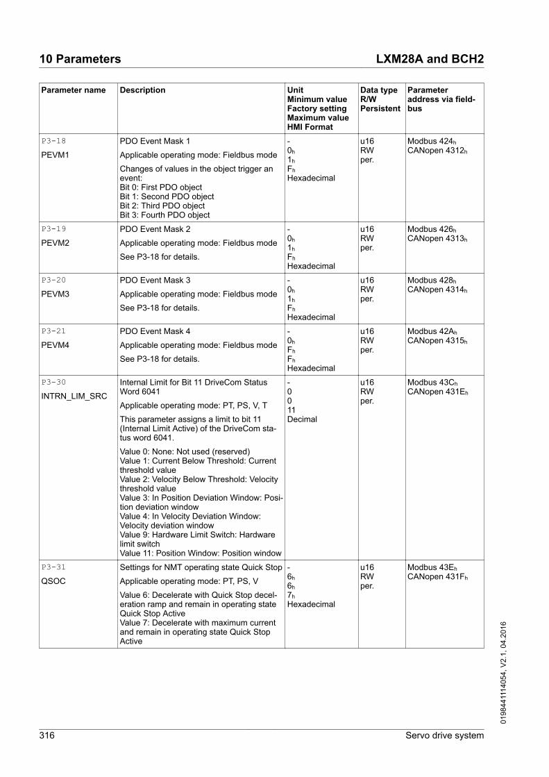
Parameter name Description UnitMinimum valueFactory settingMaximum valueHMI Format
Data typeR/WPersistent
Parameteraddress via field-bus
P3-18PEVM1
PDO Event Mask 1
Applicable operating mode: Fieldbus mode
Changes of values in the object trigger anevent:Bit 0: First PDO objectBit 1: Second PDO objectBit 2: Third PDO objectBit 3: Fourth PDO object
-0h 1h Fh Hexadecimal
u16RWper.
Modbus 424h CANopen 4312h
P3-19PEVM2
PDO Event Mask 2
Applicable operating mode: Fieldbus mode
See P3-18 for details.
-0h 1h Fh Hexadecimal
u16RWper.
Modbus 426h CANopen 4313h
P3-20PEVM3
PDO Event Mask 3
Applicable operating mode: Fieldbus mode
See P3-18 for details.
-0h 1h Fh Hexadecimal
u16RWper.
Modbus 428h CANopen 4314h
P3-21PEVM4
PDO Event Mask 4
Applicable operating mode: Fieldbus mode
See P3-18 for details.
-0h Fh Fh Hexadecimal
u16RWper.
Modbus 42Ah CANopen 4315h
P3-30INTRN_LIM_SRC
Internal Limit for Bit 11 DriveCom StatusWord 6041
Applicable operating mode: PT, PS, V, T
This parameter assigns a limit to bit 11(Internal Limit Active) of the DriveCom sta-tus word 6041.
Value 0: None: Not used (reserved)Value 1: Current Below Threshold: Currentthreshold valueValue 2: Velocity Below Threshold: Velocitythreshold valueValue 3: In Position Deviation Window: Posi-tion deviation windowValue 4: In Velocity Deviation Window:Velocity deviation windowValue 9: Hardware Limit Switch: Hardwarelimit switchValue 11: Position Window: Position window
-0011Decimal
u16RWper.
Modbus 43Ch CANopen 431Eh
P3-31QSOC
Settings for NMT operating state Quick Stop
Applicable operating mode: PT, PS, V
Value 6: Decelerate with Quick Stop decel-eration ramp and remain in operating stateQuick Stop ActiveValue 7: Decelerate with maximum currentand remain in operating state Quick StopActive
-6h 6h 7h Hexadecimal
u16RWper.
Modbus 43Eh CANopen 431Fh
10 Parameters LXM28A and BCH2
316 Servo drive system
0198
4411
1405
4, V
2.1,
04.
2016

Parameter name Description UnitMinimum valueFactory settingMaximum valueHMI Format
Data typeR/WPersistent
Parameteraddress via field-bus
P3-32SOD2RTSO
Automatic operating state transition fromSwitch On Disabled to Ready To Switch On
Applicable operating mode: PT, PS, V, T
Value 0: Transition according to value ofCANopen control wordValue 1: Automatic transition
-0h 0h 1h Hexadecimal
u16RWper.
Modbus 440h CANopen 4320h
P4-00ASH1
Error History - Error Code of Most RecentDetected Error n
Applicable operating mode: PT, PS, V, T
This parameter indicates the error code ofthe most recent detected error.
Writing 0 to this parameter clears the errorhistory.
-0h 0h 0h Hexadecimal
u16RW-
Modbus 500h CANopen 4400h
P4-01ASH2
Error History - Error Code of Most RecentDetected Error n - 1
Applicable operating mode: PT, PS, V, T
This parameter indicates the error code ofthe detected error n-1, n being the mostrecent detected error.
-0h 0h 0h Hexadecimal
u16RO-
Modbus 502h CANopen 4401h
P4-02ASH3
Error History - Error Code of Most RecentDetected Error n - 2
Applicable operating mode: PT, PS, V, T
This parameter indicates the error code ofthe detected error n-2, n being the mostrecent detected error.
-0h 0h 0h Hexadecimal
u16RO-
Modbus 504h CANopen 4402h
P4-03ASH4
Error History - Error Code of Most RecentDetected Error n - 3
Applicable operating mode: PT, PS, V, T
This parameter indicates the error code ofthe detected error n-3, n being the mostrecent detected error.
-0h 0h 0h Hexadecimal
u16RO-
Modbus 506h CANopen 4403h
P4-04ASH5
Error History - Error Code of Most RecentDetected Error n - 4
Applicable operating mode: PT, PS, V, T
This parameter indicates the error code ofthe detected error n-4, n being the mostrecent detected error.
-0h 0h 0h Hexadecimal
u16RO-
Modbus 508h CANopen 4404h
P4-05JOG
Jog Velocity
Applicable operating mode: PT, PS, V, T
See chapter "7.3.2 Jog operation" fordetails.
rpm0205000Decimal
u32RWper.
Modbus 50Ah CANopen 4405h
LXM28A and BCH2 10 Parameters
Servo drive system 317
0198
4411
1405
4, V
2.1,
04.
2016

Parameter name Description UnitMinimum valueFactory settingMaximum valueHMI Format
Data typeR/WPersistent
Parameteraddress via field-bus
P4-06FOT
Setting a signal output via parameter
Applicable operating mode: PT, PS, V, T
This parameter lets you set those signaloutputs whose signal output functions havebeen set to SDO_0 ... SDO_5.
Bit 0 = 1 sets those signal outputs whosesignal output function has been set toSDO_0.
Bit 1 = 1 sets those signal outputs whosesignal output function has been set toSDO_1.
Bit 2 = 1 sets those signal outputs whosesignal output function has been set toSDO_2.
Bit 3 = 1 sets those signal outputs whosesignal output function has been set toSDO_3.
Bit 4 = 1 sets those signal outputs whosesignal output function has been set toSDO_4.
Bit 5 = 1 sets those signal outputs whosesignal output function has been set toSDO_5.
Bit 6 = 1 sets those signal outputs whosesignal output function has been set toSDO_6.
Bit 7 = 1 sets those signal outputs whosesignal output function has been set toSDO_7.
See P2-18 ... P2-22 for assigning the func-tions to the digital outputs.
-0h 0h FFh Hexadecimal
u16RW-
Modbus 50Ch CANopen 4406h
10 Parameters LXM28A and BCH2
318 Servo drive system
0198
4411
1405
4, V
2.1,
04.
2016

Parameter name Description UnitMinimum valueFactory settingMaximum valueHMI Format
Data typeR/WPersistent
Parameteraddress via field-bus
P4-07ITST
State of Digital Inputs / Activate Forcing
Applicable operating mode: PT, PS, V, T
A read access to this parameter indicatesthe state of the digital inputs in the form of abit pattern.
Example:
Read value 0x0011: Digital inputs 1 and 5are logical 1
By writing this parameter, you can changethe state of the inputs provided that the set-ting for the corresponding input in P3-06allows for forcing (value 1 for the bit corre-sponding to the input).
Example:
Write value 0x0011: Digital inputs 1 and 5are set to logical 1, regardless of the previ-ous state
See P3-06 for permitting forcing of individ-ual digital inputs.
See P2-10 ... P2-17 for the assignment ofsignal input functions to the digital inputs.
-0h 0h FFh Hexadecimal
u16RW-
Modbus 50Eh CANopen 4407h
P4-08PKEY
Status of HMI Keypad
Applicable operating mode: PT, PS, V, T
This parameter is used to verify properoperation of the keys on the HMI keypad ofthe drive: ENT, UP, DOWN, M and S.
-0h 0h FFh Hexadecimal
u16RO-
Modbus 510h CANopen 4408h
P4-09MOT
State of Digital Outputs
Applicable operating mode: PT, PS, V, T
This parameter indicates the state of thedigital outputs DO1 ... DO6.
Bit 0 = 1: DO1 is activatedBit 1 = 1: DO2 is activatedBit 2 = 1: DO3 is activatedBit 3 = 1: DO4 is activatedBit 4 = 1: DO5 is activatedBit 5 = 1: DO6 is activated
-0h 0h 3Fh Hexadecimal
u16RO-
Modbus 512h CANopen 4409h
P4-10FLTHISTCLR
Clear Error History
Applicable operating mode: PT, PS, V, T
Writing 0 to this parameter clears the errorhistory.
-000Decimal
u16RW-
Modbus 514h CANopen 440Ah
P4-22ANIN1OFFSET
Analog Input 1 Offset
Applicable operating mode: V
This parameter specifies an offset for theanalog input used in operating mode V.
mV-10000010000Decimal
s16RWper.
Modbus 52Ch CANopen 4416h
P4-23ANIN2OFFSET
Analog Input 2 Offset
Applicable operating mode: T
This parameter specifies an offset for theanalog input used in operating mode T.
mV-10000010000Decimal
s16RWper.
Modbus 52Eh CANopen 4417h
LXM28A and BCH2 10 Parameters
Servo drive system 319
0198
4411
1405
4, V
2.1,
04.
2016

Parameter name Description UnitMinimum valueFactory settingMaximum valueHMI Format
Data typeR/WPersistent
Parameteraddress via field-bus
P4-24LVL
Undervoltage Monitoring - Threshold Value
Applicable operating mode: PT, PS, V, T
This parameter specifies the threshold valuefor DC bus undervoltage monitoring. If theDC Bus voltage is less than the value ofP4-24 x 2, the error AL003 is detected.
V140160190Decimal
u16RWper.
Modbus 530h CANopen 4418h
P4-25STO
Safety Function STO - Status
Applicable operating mode: PT, PS, V, T
This parameter indicates the status of thesafety function STO.
Bit 0 = 0: Safety function STO triggeredBit 0 = 1: Safety function STO not triggeredor deactivated via jumper at CN9
-0-1Decimal
u16RO-
Modbus 532h CANopen 4419h
P4-26DO_FORCEABLE
Digital Outputs - Forcing Information
Applicable operating mode: PT, PS, V, T
This parameter shows whether or not a digi-tal output can be forced.
Bits 0 ... 4: Digital output DO1 ... digital out-put DO5
Bit settings:
Value 0: Digital output cannot be forced
Value 1: Digital output can be forced
-1Fh 1Fh 1Fh Hexadecimal
u16RO-
Modbus 534h CANopen 441Ah
P4-27DO_FORCE_MASK
Digital Outputs - Forcing Settings
Applicable operating mode: PT, PS, V, T
This parameter determines whether or not adigital output can be forced.
Bits 0 ... 4: Digital output DO1 ... digital out-put DO5
Bit settings:
Value 0: Digital output cannot be forced
Value 1: Digital output can be forced
To actually start forcing, you must writeP4-28.
See P2-18 ... P2-22 for the assignment ofsignal output functions to the digital outputs.
-0h 0h 1Fh Hexadecimal
u16RW-
Modbus 536h CANopen 441Bh
10 Parameters LXM28A and BCH2
320 Servo drive system
0198
4411
1405
4, V
2.1,
04.
2016

Parameter name Description UnitMinimum valueFactory settingMaximum valueHMI Format
Data typeR/WPersistent
Parameteraddress via field-bus
P4-28DO_FORCE_VALUE
State of Digital Outputs / Activate Forcing
Applicable operating mode: PT, PS, V, T
A read access to this parameter indicatesthe state of the digital outputs in the form ofa bit pattern.
Example:
Read value 0x0011: Digital outputs 1 and 5are logical 1
By writing this parameter, you can changethe state of the outputs provided that thesetting for the corresponding output inP4-27 allows for forcing (value 1 for the bitcorresponding to the output).
Example:
Write value 0x0011: Digital outputs 1 and 5are set to logical 1, regardless of the previ-ous state
See P4-27 for permitting forcing of individ-ual digital outputs.
See P2-18 ... P2-22 for the assignment ofsignal output functions to the digital outputs.
-0h 0h 1Fh Hexadecimal
u16RW-
Modbus 538h CANopen 441Ch
P5-00REV
Firmware Revision
Applicable operating mode: PT, PS, V, T
This parameter contains the revision num-ber of the firmware.
-0h 0h FFFFh Hexadecimal
u16RO-
Modbus 600h CANopen 4500h
P5-04HMOV
Homing - Homing Method Selection
Applicable operating mode: PS
This parameter is used to select the homingmethod and configure the behavior of theindex pulse and the limit switches.
See chapter"7.3.4 Operating mode Position Sequence(PS)" for details.
Setting can only be changed if power stageis disabled.
-0h 0h 128h Hexadecimal
u16RWper.
Modbus 608h CANopen 4504h
P5-05HOMESPEED1
Homing - Fast Velocity for Reference Move-ment
Applicable operating mode: PS
0.1rpm10100060000Decimal
u32RWper.
Modbus 60Ah CANopen 4505h
P5-06HOMESPEED2
Homing - Slow Velocity for Reference Move-ment
Applicable operating mode: PS
0.1rpm1020060000Decimal
u32RWper.
Modbus 60Ch CANopen 4506h
LXM28A and BCH2 10 Parameters
Servo drive system 321
0198
4411
1405
4, V
2.1,
04.
2016

Parameter name Description UnitMinimum valueFactory settingMaximum valueHMI Format
Data typeR/WPersistent
Parameteraddress via field-bus
P5-07PRCM
Operating Mode PS via Parameter
Applicable operating mode: PS
The operating mode Position Sequence(PS) provides 32 data sets that can be exe-cuted via the signal input functionsPOS0 ... POS4 and CTRG or via of thisparameter.
0: Start operating mode Homing (Homingdata set)
1 ... 32: Trigger data set (equivalent to thesignal input functions CTRG and POSn).
33 ... 9999: Not permitted
1000: Stop movement (equivalent to the sig-nal input function STOP)
Values displayed via this parameter:
If a data set is active, but not yet completed,the value displayed is the value of thisparameter plus 10000.
If a data set has been completed, the valuedisplayed is the value of this parameter plus20000.
Example:
Displayed value 10003: Data set 3 has beenstarted, but is not yet completed.
Displayed value 20003: Data set 3 has beencompleted.
See chapter"7.3.4 Operating mode Position Sequence(PS)".
-001000Decimal
u16RW-
Modbus 60Eh CANopen 4507h
P5-08POSLIMPOS
Positive Software Limit Switch - Position
Applicable operating mode: PS
Setting can only be changed if power stageis disabled.
PUU-21474836471342177272147483647Decimal
s32RWper.
Modbus 610h CANopen 4508h
P5-09POSLIMNEG
Negative Software Limit Switch - Position
Applicable operating mode: PS
Setting can only be changed if power stageis disabled.
PUU-2147483647-1342177272147483647Decimal
s32RWper.
Modbus 612h CANopen 4509h
P5-10GEARACC-THRESH
Operating mode Pulse Train - MaximumAcceleration
Applicable operating mode: PT
ms6665500Decimal
u16RWper.
Modbus 614h CANopen 450Ah
P5-11POSLIMHYST
Software Limit Switches - Hysteresis Value
Applicable operating mode: PT, PS, V, T
This parameter specifies a hysteresis valuefor the software limit switches.
Setting can only be changed if power stageis disabled.
PULSE0355635555Decimal
u16RWper.
Modbus 616h CANopen 450Bh
10 Parameters LXM28A and BCH2
322 Servo drive system
0198
4411
1405
4, V
2.1,
04.
2016

Parameter name Description UnitMinimum valueFactory settingMaximum valueHMI Format
Data typeR/WPersistent
Parameteraddress via field-bus
P5-12PROBE_1_LVL_PRD
Touch Probe Input 1 - Stable Level Duration
Applicable operating mode: PT, PS
This parameter specifies the period of timefor which the level at Touch Probe input 1must be stable.
-2532Decimal
u16RWper.
Modbus 618h CANopen 450Ch
P5-13POSLIMMODE
Software Limit Switches - Activation
Applicable operating mode: PT, PS, ?, ?
This parameter activates/deactivates thesoftware limit switches configured via P5-08and P5-09.
Value 0: Deactivate software limit switchesValue 1: Activate software limit switches
-001Decimal
u16RWper.
Modbus 61Ah CANopen 450Dh
P5-14ICMDSLOPE
Motion Profile for Torque - Slope
Applicable operating mode: T
This parameter specifies the slope of themotion profile for torque.
mA/s110000030000000Decimal
u32RWper.
Modbus 61Ch CANopen 450Eh
P5-15ICMDSLOPEEN
Motion Profile for Torque - Activation
Applicable operating mode: T
This parameter activates the motion profilefor torque.
Value 0: ActivateValue 1: Deactivate
Setting can only be changed if power stageis disabled.
-001Decimal
u16RWper.
Modbus 61Eh CANopen 450Fh
P5-16AXEN
Encoder Increments in PUU
Applicable operating mode: PT, PS, V, T
Setting can only be changed if power stageis disabled.
PUU-214748364702147483647Decimal
s32RW-
Modbus 620h CANopen 4510h
P5-18AXPC
External Encoder (Pulses)
Applicable operating mode: PT, PS, V, T
--2147483648-2147483647Decimal
s32RO-
Modbus 624h CANopen 4512h
P5-20STP
Deceleration Ramp - Signal Input FunctionSTOP
Applicable operating mode: PT, PS, V
This parameter specifies the decelerationramp for a stop triggered via the signal inputfunction STOP.The deceleration period is the time in milli-seconds required to decelerate from 6000min-1 to motor standstill. It is used to set thedeceleration ramp.
ms65065500Decimal
u16RWper.
Modbus 628h CANopen 4514h
LXM28A and BCH2 10 Parameters
Servo drive system 323
0198
4411
1405
4, V
2.1,
04.
2016

Parameter name Description UnitMinimum valueFactory settingMaximum valueHMI Format
Data typeR/WPersistent
Parameteraddress via field-bus
P5-21CTO
Deceleration Ramp - Detected TransmissionError
Applicable operating mode: PT, PS, V
This parameter specifies the decelerationramp for a stop triggered if a transmissionerror is detected.The deceleration period is the time in milli-seconds required to decelerate from 6000min-1 to motor standstill. It is used to set thedeceleration ramp.
ms65065500Decimal
u16RWper.
Modbus 62Ah CANopen 4515h
P5-22OVF
Deceleration Ramp - Position Overflow
Applicable operating mode: PT, PS, V
This parameter specifies the decelerationramp for a stop triggered if a position over-flow is detected.The deceleration period is the time in milli-seconds required to decelerate from 6000min-1 to motor standstill. It is used to set thedeceleration ramp.
ms63065500Decimal
u16RWper.
Modbus 62Ch CANopen 4516h
P5-23SNL
Deceleration Ramp - Triggering of NegativeSoftware Limit Switch
Applicable operating mode: PT, PS, V
This parameter specifies the decelerationramp for a stop triggered if the negativesoftware limit switch is activated.The deceleration period is the time in milli-seconds required to decelerate from 6000min-1 to motor standstill. It is used to set thedeceleration ramp.
ms65065500Decimal
u16RWper.
Modbus 62Eh CANopen 4517h
P5-24SPL
Deceleration Ramp - Triggering of PositiveSoftware Limit Switch
Applicable operating mode: PT, PS, V
This parameter specifies the decelerationramp for a stop triggered if the positive soft-ware limit switch is activated.The deceleration period is the time in milli-seconds required to decelerate from 6000min-1 to motor standstill. It is used to set thedeceleration ramp.
ms65065500Decimal
u16RWper.
Modbus 630h CANopen 4518h
P5-25NL
Deceleration Ramp - Triggering of NegativeHardware Limit Switch
Applicable operating mode: PT, PS, V
This parameter specifies the decelerationramp for a stop triggered if the negativehardware limit switch is activated.The deceleration period is the time in milli-seconds required to decelerate from 6000min-1 to motor standstill. It is used to set thedeceleration ramp.
ms63065500Decimal
u16RWper.
Modbus 632h CANopen 4519h
10 Parameters LXM28A and BCH2
324 Servo drive system
0198
4411
1405
4, V
2.1,
04.
2016

Parameter name Description UnitMinimum valueFactory settingMaximum valueHMI Format
Data typeR/WPersistent
Parameteraddress via field-bus
P5-26PL
Deceleration Ramp - Triggering of PositiveHardware Limit Switch
Applicable operating mode: PT, PS, V
This parameter specifies the decelerationramp for a stop triggered if the positivehardware limit switch is activated.The deceleration period is the time in milli-seconds required to decelerate from 6000min-1 to motor standstill. It is used to set thedeceleration ramp.
ms63065500Decimal
u16RWper.
Modbus 634h CANopen 451Ah
P5-37CAAX
Touch Probe Input 1 - Captured Position
Applicable operating mode: PT, PS, V, T
This parameter contains the position cap-tured at Touch Probe input 1.
PUU-214748364702147483647Decimal
s32RO-
Modbus 64Ah CANopen 4525h
P5-38PROBE1_CNTR
Touch Probe Input 1 - Event Counter
Applicable operating mode: PT, PS, V, T
The value is increased by 1 each time aposition has been captured at Touch Probeinput 1.
-0065535Decimal
u16RO-
Modbus 64Ch CANopen 4526h
P5-39CACT
Touch Probe Input 1 - Configuration
Applicable operating mode: PT, PS, V, T
X: Activate/deactivate position capture0: Deactivate1: Activate (is reset to 0 when the counter inP5-38 is incremented)
Y: Reserved
Z: Polarity of Touch Probe input0: Normally open1: Normally closed
U: Reserved
-0h 0h 101h Hexadecimal
u16RW-
Modbus 64Eh CANopen 4527h
P5-57CAAX2
Touch Probe Input 2 - Captured Position
Applicable operating mode: PT, PS, V, T
This parameter contains the position cap-tured at Touch Probe input 2.
PUU-214748364702147483647Decimal
s32RO-
Modbus 672h CANopen 4539h
P5-58PROBE2_CNTR
Touch Probe Input 2 - Event Counter
Applicable operating mode: PT, PS, V, T
The value is increased by 1 each time aposition has been captured at Touch Probeinput 2.
-0065535Decimal
u16RO-
Modbus 674h CANopen 453Ah
LXM28A and BCH2 10 Parameters
Servo drive system 325
0198
4411
1405
4, V
2.1,
04.
2016

Parameter name Description UnitMinimum valueFactory settingMaximum valueHMI Format
Data typeR/WPersistent
Parameteraddress via field-bus
P5-59CACT2
Touch Probe Input 2 - Configuration
Applicable operating mode: PT, PS, V, T
X: Activate/deactivate position capture0: Deactivate1: Activate (is reset to 0 when the counter inP5-58 is incremented)
Y: Reserved
Z: Polarity of Touch Probe input0: Normally open1: Normally closed
U: Reserved
-0h 0h 101h Hexadecimal
u16RW-
Modbus 676h CANopen 453Bh
P5-77PROBE_2_LVL_PRD
Touch Probe Input 2 - Stable Level Duration
Applicable operating mode: PT, PS
This parameter specifies the period of timefor which the level at Touch Probe input 2must be stable.
-2532Decimal
u16RWper.
Modbus 69Ah CANopen 454Dh
P6-00ODAT
Position of Homing Data Set
Applicable operating mode: PS
After a successful reference movement, thisposition is automatically set at the referencepoint.
Bits 0 ... 31: Position
PUU-214748364702147483647Decimal
s32RWper.
Modbus 700h CANopen 4600h
P6-01ODEF
Subsequent Data Set and Auto-start ofHoming Data Set
Applicable operating mode: PS
Bit 0:0 = Do not start Homing after first powerstage enable1 = Start Homing after first power stageenable
Bits 1 ... 7: Reserved
Bits 8 ... 15: Subsequent data set
-0h 0h 2001h Hexadecimal
u32RWper.
Modbus 702h CANopen 4601h
P6-02PATHPOS1
Target Position of Data Set 1
Applicable operating mode: PS
Bits 0 ... 31: Target position
PUU-214748364702147483647Decimal
s32RWper.
Modbus 704h CANopen 4602h
10 Parameters LXM28A and BCH2
326 Servo drive system
0198
4411
1405
4, V
2.1,
04.
2016

Parameter name Description UnitMinimum valueFactory settingMaximum valueHMI Format
Data typeR/WPersistent
Parameteraddress via field-bus
P6-03PATHCTRL1
Configuration of Data Set 1
Applicable operating mode: PS
Bits 0 ... 3: Reserved
Bit 4:0 = Wait for preceding data set to complete,then start this data set1 = Start this data set immediately
Bits 5 ... 6: Reserved
Bit 7:0 = Absolute position1 = Relative (incremental) position
Bits 8 ... 15: Reserved
-0h 0h 90h Hexadecimal
u16RWper.
Modbus 706h CANopen 4603h
P6-04PATHPOS2
Target Position of Data Set 2
Applicable operating mode: PS
See P6-02 for details.
PUU-214748364702147483647Decimal
s32RWper.
Modbus 708h CANopen 4604h
P6-05PATHCTRL2
Configuration of Data Set 2
Applicable operating mode: PS
See P6-03 for details.
-0h 0h 90h Hexadecimal
u16RWper.
Modbus 70Ah CANopen 4605h
P6-06PATHPOS3
Target Position of Data Set 3
Applicable operating mode: PS
See P6-02 for details.
PUU-214748364702147483647Decimal
s32RWper.
Modbus 70Ch CANopen 4606h
P6-07PATHCTRL3
Configuration of Data Set 3
Applicable operating mode: PS
See P6-03 for details.
-0h 0h 90h Hexadecimal
u16RWper.
Modbus 70Eh CANopen 4607h
P6-08PATHPOS4
Target Position of Data Set 4
Applicable operating mode: PS
See P6-02 for details.
PUU-214748364702147483647Decimal
s32RWper.
Modbus 710h CANopen 4608h
P6-09PATHCTRL4
Configuration of Data Set 4
Applicable operating mode: PS
See P6-03 for details.
-0h 0h 90h Hexadecimal
u16RWper.
Modbus 712h CANopen 4609h
P6-10PATHPOS5
Target Position of Data Set 5
Applicable operating mode: PS
See P6-02 for details.
PUU-214748364702147483647Decimal
s32RWper.
Modbus 714h CANopen 460Ah
P6-11PATHCTRL5
Configuration of Data Set 5
Applicable operating mode: PS
See P6-03 for details.
-0h 0h 90h Hexadecimal
u16RWper.
Modbus 716h CANopen 460Bh
LXM28A and BCH2 10 Parameters
Servo drive system 327
0198
4411
1405
4, V
2.1,
04.
2016

Parameter name Description UnitMinimum valueFactory settingMaximum valueHMI Format
Data typeR/WPersistent
Parameteraddress via field-bus
P6-12PATHPOS6
Target Position of Data Set 6
Applicable operating mode: PS
See P6-02 for details.
PUU-214748364702147483647Decimal
s32RWper.
Modbus 718h CANopen 460Ch
P6-13PATHCTRL6
Configuration of Data Set 6
Applicable operating mode: PS
See P6-03 for details.
-0h 0h 90h Hexadecimal
u16RWper.
Modbus 71Ah CANopen 460Dh
P6-14PATHPOS7
Target Position of Data Set 7
Applicable operating mode: PS
See P6-02 for details.
PUU-214748364702147483647Decimal
s32RWper.
Modbus 71Ch CANopen 460Eh
P6-15PATHCTRL7
Configuration of Data Set 7
Applicable operating mode: PS
See P6-03 for details.
-0h 0h 90h Hexadecimal
u16RWper.
Modbus 71Eh CANopen 460Fh
P6-16PATHPOS8
Target Position of Data Set 8
Applicable operating mode: PS
See P6-02 for details.
PUU-214748364702147483647Decimal
s32RWper.
Modbus 720h CANopen 4610h
P6-17PATHCTRL8
Configuration of Data Set 8
Applicable operating mode: PS
See P6-03 for details.
-0h 0h 90h Hexadecimal
u16RWper.
Modbus 722h CANopen 4611h
P6-18PATHPOS9
Target Position of Data Set 9
Applicable operating mode: PS
See P6-02 for details.
PUU-214748364702147483647Decimal
s32RWper.
Modbus 724h CANopen 4612h
P6-19PATHCTRL9
Configuration of Data Set 9
Applicable operating mode: PS
See P6-03 for details.
-0h 0h 90h Hexadecimal
u16RWper.
Modbus 726h CANopen 4613h
P6-20PATHPOS10
Target Position of Data Set 10
Applicable operating mode: PS
See P6-02 for details.
PUU-214748364702147483647Decimal
s32RWper.
Modbus 728h CANopen 4614h
P6-21PATHCTRL10
Configuration of Data Set 10
Applicable operating mode: PS
See P6-03 for details.
-0h 0h 90h Hexadecimal
u16RWper.
Modbus 72Ah CANopen 4615h
P6-22PATHPOS11
Target Position of Data Set 11
Applicable operating mode: PS
See P6-02 for details.
PUU-214748364702147483647Decimal
s32RWper.
Modbus 72Ch CANopen 4616h
10 Parameters LXM28A and BCH2
328 Servo drive system
0198
4411
1405
4, V
2.1,
04.
2016

Parameter name Description UnitMinimum valueFactory settingMaximum valueHMI Format
Data typeR/WPersistent
Parameteraddress via field-bus
P6-23PATHCTRL11
Configuration of Data Set 11
Applicable operating mode: PS
See P6-03 for details.
-0h 0h 90h Hexadecimal
u16RWper.
Modbus 72Eh CANopen 4617h
P6-24PATHPOS12
Target Position of Data Set 12
Applicable operating mode: PS
See P6-02 for details.
PUU-214748364702147483647Decimal
s32RWper.
Modbus 730h CANopen 4618h
P6-25PATHCTRL12
Configuration of Data Set 12
Applicable operating mode: PS
See P6-03 for details.
-0h 0h 90h Hexadecimal
u16RWper.
Modbus 732h CANopen 4619h
P6-26PATHPOS13
Target Position of Data Set 13
Applicable operating mode: PS
See P6-02 for details.
PUU-214748364702147483647Decimal
s32RWper.
Modbus 734h CANopen 461Ah
P6-27PATHCTRL13
Configuration of Data Set 13
Applicable operating mode: PS
See P6-03 for details.
-0h 0h 90h Hexadecimal
u16RWper.
Modbus 736h CANopen 461Bh
P6-28PATHPOS14
Target Position of Data Set 14
Applicable operating mode: PS
See P6-02 for details.
PUU-214748364702147483647Decimal
s32RWper.
Modbus 738h CANopen 461Ch
P6-29PATHCTRL14
Configuration of Data Set 14
Applicable operating mode: PS
See P6-03 for details.
-0h 0h 90h Hexadecimal
u16RWper.
Modbus 73Ah CANopen 461Dh
P6-30PATHPOS15
Target Position of Data Set 15
Applicable operating mode: PS
See P6-02 for details.
PUU-214748364702147483647Decimal
s32RWper.
Modbus 73Ch CANopen 461Eh
P6-31PATHCTRL15
Configuration of Data Set 15
Applicable operating mode: PS
See P6-03 for details.
-0h 0h 90h Hexadecimal
u16RWper.
Modbus 73Eh CANopen 461Fh
P6-32PATHPOS16
Target Position of Data Set 16
Applicable operating mode: PS
See P6-02 for details.
PUU-214748364702147483647Decimal
s32RWper.
Modbus 740h CANopen 4620h
P6-33PATHCTRL16
Configuration of Data Set 16
Applicable operating mode: PS
See P6-03 for details.
-0h 0h 90h Hexadecimal
u16RWper.
Modbus 742h CANopen 4621h
LXM28A and BCH2 10 Parameters
Servo drive system 329
0198
4411
1405
4, V
2.1,
04.
2016

Parameter name Description UnitMinimum valueFactory settingMaximum valueHMI Format
Data typeR/WPersistent
Parameteraddress via field-bus
P6-34PATHPOS17
Target Position of Data Set 17
Applicable operating mode: PS
See P6-02 for details.
PUU-214748364702147483647Decimal
s32RWper.
Modbus 744h CANopen 4622h
P6-35PATHCTRL17
Configuration of Data Set 17
Applicable operating mode: PS
See P6-03 for details.
-0h 0h 90h Hexadecimal
u16RWper.
Modbus 746h CANopen 4623h
P6-36PATHPOS18
Target Position of Data Set 18
Applicable operating mode: PS
See P6-02 for details.
PUU-214748364702147483647Decimal
s32RWper.
Modbus 748h CANopen 4624h
P6-37PATHCTRL18
Configuration of Data Set 18
Applicable operating mode: PS
See P6-03 for details.
-0h 0h 90h Hexadecimal
u16RWper.
Modbus 74Ah CANopen 4625h
P6-38PATHPOS19
Target Position of Data Set 19
Applicable operating mode: PS
See P6-02 for details.
PUU-214748364702147483647Decimal
s32RWper.
Modbus 74Ch CANopen 4626h
P6-39PATHCTRL19
Configuration of Data Set 19
Applicable operating mode: PS
See P6-03 for details.
-0h 0h 90h Hexadecimal
u16RWper.
Modbus 74Eh CANopen 4627h
P6-40PATHPOS20
Target Position of Data Set 20
Applicable operating mode: PS
See P6-02 for details.
PUU-214748364702147483647Decimal
s32RWper.
Modbus 750h CANopen 4628h
P6-41PATHCTRL20
Configuration of Data Set 20
Applicable operating mode: PS
See P6-03 for details.
-0h 0h 90h Hexadecimal
u16RWper.
Modbus 752h CANopen 4629h
P6-42PATHPOS21
Target Position of Data Set 21
Applicable operating mode: PS
See P6-02 for details.
PUU-214748364702147483647Decimal
s32RWper.
Modbus 754h CANopen 462Ah
P6-43PATHCTRL21
Configuration of Data Set 21
Applicable operating mode: PS
See P6-03 for details.
-0h 0h 90h Hexadecimal
u16RWper.
Modbus 756h CANopen 462Bh
P6-44PATHPOS22
Target Position of Data Set 22
Applicable operating mode: PS
See P6-02 for details.
PUU-214748364702147483647Decimal
s32RWper.
Modbus 758h CANopen 462Ch
10 Parameters LXM28A and BCH2
330 Servo drive system
0198
4411
1405
4, V
2.1,
04.
2016

Parameter name Description UnitMinimum valueFactory settingMaximum valueHMI Format
Data typeR/WPersistent
Parameteraddress via field-bus
P6-45PATHCTRL22
Configuration of Data Set 22
Applicable operating mode: PS
See P6-03 for details.
-0h 0h 90h Hexadecimal
u16RWper.
Modbus 75Ah CANopen 462Dh
P6-46PATHPOS23
Target Position of Data Set 23
Applicable operating mode: PS
See P6-02 for details.
PUU-214748364702147483647Decimal
s32RWper.
Modbus 75Ch CANopen 462Eh
P6-47PATHCTRL23
Configuration of Data Set 23
Applicable operating mode: PS
See P6-03 for details.
-0h 0h 90h Hexadecimal
u16RWper.
Modbus 75Eh CANopen 462Fh
P6-48PATHPOS24
Target Position of Data Set 24
Applicable operating mode: PS
See P6-02 for details.
PUU-214748364702147483647Decimal
s32RWper.
Modbus 760h CANopen 4630h
P6-49PATHCTRL24
Configuration of Data Set 24
Applicable operating mode: PS
See P6-03 for details.
-0h 0h 90h Hexadecimal
u16RWper.
Modbus 762h CANopen 4631h
P6-50PATHPOS25
Target Position of Data Set 25
Applicable operating mode: PS
See P6-02 for details.
PUU-214748364702147483647Decimal
s32RWper.
Modbus 764h CANopen 4632h
P6-51PATHCTRL25
Configuration of Data Set 25
Applicable operating mode: PS
See P6-03 for details.
-0h 0h 90h Hexadecimal
u16RWper.
Modbus 766h CANopen 4633h
P6-52PATHPOS26
Target Position of Data Set 26
Applicable operating mode: PS
See P6-02 for details.
PUU-214748364702147483647Decimal
s32RWper.
Modbus 768h CANopen 4634h
P6-53PATHCTRL26
Configuration of Data Set 26
Applicable operating mode: PS
See P6-03 for details.
-0h 0h 90h Hexadecimal
u16RWper.
Modbus 76Ah CANopen 4635h
P6-54PATHPOS27
Target Position of Data Set 27
Applicable operating mode: PS
See P6-02 for details.
PUU-214748364702147483647Decimal
s32RWper.
Modbus 76Ch CANopen 4636h
P6-55PATHCTRL27
Configuration of Data Set 27
Applicable operating mode: PS
See P6-03 for details.
-0h 0h 90h Hexadecimal
u16RWper.
Modbus 76Eh CANopen 4637h
LXM28A and BCH2 10 Parameters
Servo drive system 331
0198
4411
1405
4, V
2.1,
04.
2016

Parameter name Description UnitMinimum valueFactory settingMaximum valueHMI Format
Data typeR/WPersistent
Parameteraddress via field-bus
P6-56PATHPOS28
Target Position of Data Set 28
Applicable operating mode: PS
See P6-02 for details.
PUU-214748364702147483647Decimal
s32RWper.
Modbus 770h CANopen 4638h
P6-57PATHCTRL28
Configuration of Data Set 28
Applicable operating mode: PS
See P6-03 for details.
-0h 0h 90h Hexadecimal
u16RWper.
Modbus 772h CANopen 4639h
P6-58PATHPOS29
Target Position of Data Set 29
Applicable operating mode: PS
See P6-02 for details.
PUU-214748364702147483647Decimal
s32RWper.
Modbus 774h CANopen 463Ah
P6-59PATHCTRL29
Configuration of Data Set 29
Applicable operating mode: PS
See P6-03 for details.
-0h 0h 90h Hexadecimal
u16RWper.
Modbus 776h CANopen 463Bh
P6-60PATHPOS30
Target Position of Data Set 30
Applicable operating mode: PS
See P6-02 for details.
PUU-214748364702147483647Decimal
s32RWper.
Modbus 778h CANopen 463Ch
P6-61PATHCTRL30
Configuration of Data Set 30
Applicable operating mode: PS
See P6-03 for details.
-0h 0h 90h Hexadecimal
u16RWper.
Modbus 77Ah CANopen 463Dh
P6-62PATHPOS31
Target Position of Data Set 31
Applicable operating mode: PS
See P6-02 for details.
PUU-214748364702147483647Decimal
s32RWper.
Modbus 77Ch CANopen 463Eh
P6-63PATHCTRL31
Configuration of Data Set 31
Applicable operating mode: PS
See P6-03 for details.
-0h 0h 90h Hexadecimal
u16RWper.
Modbus 77Eh CANopen 463Fh
P6-64PATHPOS32
Target Position of Data Set 32
Applicable operating mode: PS
See P6-02 for details.
PUU-214748364702147483647Decimal
s32RWper.
Modbus 780h CANopen 4640h
P6-65PATHCTRL32
Configuration of Data Set 32
Applicable operating mode: PS
See P6-03 for details.
-0h 0h 90h Hexadecimal
u16RWper.
Modbus 782h CANopen 4641h
10 Parameters LXM28A and BCH2
332 Servo drive system
0198
4411
1405
4, V
2.1,
04.
2016

Parameter name Description UnitMinimum valueFactory settingMaximum valueHMI Format
Data typeR/WPersistent
Parameteraddress via field-bus
P7-00HOME_ACC_DEC
Deceleration and Acceleration of HomingData Set
Applicable operating mode: PS
Bits 0 ... 15: Deceleration
Bits 16 ... 31: Acceleration
ms|ms6| 6200| 20065500| 65500Decimal
u32RWper.
Modbus 800h CANopen 4700h
P7-01HOME_DLY
Waiting Time of Homing Data Set
Applicable operating mode: PS
Bits 0 ... 15: Waiting time until next datasetis started
Bits 16 ... 31: Reserved
ms0032767Decimal
u32RWper.
Modbus 802h CANopen 4701h
P7-02ACC_DEC1
Deceleration and Acceleration of Data Set 1
Applicable operating mode: PS
Bits 0 ... 15: Deceleration
Bits 16 ... 31: Acceleration
ms|ms6| 6200| 20065500| 65500Decimal
u32RWper.
Modbus 804h CANopen 4702h
P7-03SPD_DLY1
Waiting Time and Target Velocity of DataSet 1
Applicable operating mode: PS
Bits 0 ... 15: Waiting time until next datasetis started (in ms)
Bits 16 ... 31: Target velocity (in min-1)
0.1rpm|ms0| 0200| 060000| 32767Decimal
u32RWper.
Modbus 806h CANopen 4703h
P7-04ACC_DEC2
Deceleration and Acceleration of Data Set 2
Applicable operating mode: PS
See P7-02 for details.
ms|ms6| 6200| 20065500| 65500Decimal
u32RWper.
Modbus 808h CANopen 4704h
P7-05SPD_DLY2
Waiting Time and Target Velocity of DataSet 2
Applicable operating mode: PS
See P7-03 for details.
0.1rpm|ms0| 0200| 060000| 32767Decimal
u32RWper.
Modbus 80Ah CANopen 4705h
P7-06ACC_DEC3
Deceleration and Acceleration of Data Set 3
Applicable operating mode: PS
See P7-02 for details.
ms|ms6| 6200| 20065500| 65500Decimal
u32RWper.
Modbus 80Ch CANopen 4706h
P7-07SPD_DLY3
Waiting Time and Target Velocity of DataSet 3
Applicable operating mode: PS
See P7-03 for details.
0.1rpm|ms0| 0200| 060000| 32767Decimal
u32RWper.
Modbus 80Eh CANopen 4707h
P7-08ACC_DEC4
Deceleration and Acceleration of Data Set 4
Applicable operating mode: PS
See P7-02 for details.
ms|ms6| 6200| 20065500| 65500Decimal
u32RWper.
Modbus 810h CANopen 4708h
P7-09SPD_DLY4
Waiting Time and Target Velocity of DataSet 4
Applicable operating mode: PS
See P7-03 for details.
0.1rpm|ms0| 0200| 060000| 32767Decimal
u32RWper.
Modbus 812h CANopen 4709h
LXM28A and BCH2 10 Parameters
Servo drive system 333
0198
4411
1405
4, V
2.1,
04.
2016

Parameter name Description UnitMinimum valueFactory settingMaximum valueHMI Format
Data typeR/WPersistent
Parameteraddress via field-bus
P7-10ACC_DEC5
Deceleration and Acceleration of Data Set 5
Applicable operating mode: PS
See P7-02 for details.
ms|ms6| 6200| 20065500| 65500Decimal
u32RWper.
Modbus 814h CANopen 470Ah
P7-11SPD_DLY5
Waiting Time and Target Velocity of DataSet 5
Applicable operating mode: PS
See P7-03 for details.
0.1rpm|ms0| 0200| 060000| 32767Decimal
u32RWper.
Modbus 816h CANopen 470Bh
P7-12ACC_DEC6
Deceleration and Acceleration of Data Set 6
Applicable operating mode: PS
See P7-02 for details.
ms|ms6| 6200| 20065500| 65500Decimal
u32RWper.
Modbus 818h CANopen 470Ch
P7-13SPD_DLY6
Waiting Time and Target Velocity of DataSet 6
Applicable operating mode: PS
See P7-03 for details.
0.1rpm|ms0| 0200| 060000| 32767Decimal
u32RWper.
Modbus 81Ah CANopen 470Dh
P7-14ACC_DEC7
Deceleration and Acceleration of Data Set 7
Applicable operating mode: PS
See P7-02 for details.
ms|ms6| 6200| 20065500| 65500Decimal
u32RWper.
Modbus 81Ch CANopen 470Eh
P7-15SPD_DLY7
Waiting Time and Target Velocity of DataSet 7
Applicable operating mode: PS
See P7-03 for details.
0.1rpm|ms0| 0200| 060000| 32767Decimal
u32RWper.
Modbus 81Eh CANopen 470Fh
P7-16ACC_DEC8
Deceleration and Acceleration of Data Set 8
Applicable operating mode: PS
See P7-02 for details.
ms|ms6| 6200| 20065500| 65500Decimal
u32RWper.
Modbus 820h CANopen 4710h
P7-17SPD_DLY8
Waiting Time and Target Velocity of DataSet 8
Applicable operating mode: PS
See P7-03 for details.
0.1rpm|ms0| 0200| 060000| 32767Decimal
u32RWper.
Modbus 822h CANopen 4711h
P7-18ACC_DEC9
Deceleration and Acceleration of Data Set 9
Applicable operating mode: PS
See P7-02 for details.
ms|ms6| 6200| 20065500| 65500Decimal
u32RWper.
Modbus 824h CANopen 4712h
P7-19SPD_DLY9
Waiting Time and Target Velocity of DataSet 9
Applicable operating mode: PS
See P7-03 for details.
0.1rpm|ms0| 0200| 060000| 32767Decimal
u32RWper.
Modbus 826h CANopen 4713h
P7-20ACC_DEC10
Deceleration and Acceleration of Data Set10
Applicable operating mode: PS
See P7-02 for details.
ms|ms6| 6200| 20065500| 65500Decimal
u32RWper.
Modbus 828h CANopen 4714h
10 Parameters LXM28A and BCH2
334 Servo drive system
0198
4411
1405
4, V
2.1,
04.
2016

Parameter name Description UnitMinimum valueFactory settingMaximum valueHMI Format
Data typeR/WPersistent
Parameteraddress via field-bus
P7-21SPD_DLY10
Waiting Time and Target Velocity of DataSet 10
Applicable operating mode: PS
See P7-03 for details.
0.1rpm|ms0| 0200| 060000| 32767Decimal
u32RWper.
Modbus 82Ah CANopen 4715h
P7-22ACC_DEC11
Deceleration and Acceleration of Data Set11
Applicable operating mode: PS
See P7-02 for details.
ms|ms6| 6200| 20065500| 65500Decimal
u32RWper.
Modbus 82Ch CANopen 4716h
P7-23SPD_DLY11
Waiting Time and Target Velocity of DataSet 11
Applicable operating mode: PS
See P7-03 for details.
0.1rpm|ms0| 0200| 060000| 32767Decimal
u32RWper.
Modbus 82Eh CANopen 4717h
P7-24ACC_DEC12
Deceleration and Acceleration of Data Set12
Applicable operating mode: PS
See P7-02 for details.
ms|ms6| 6200| 20065500| 65500Decimal
u32RWper.
Modbus 830h CANopen 4718h
P7-25SPD_DLY12
Waiting Time and Target Velocity of DataSet 12
Applicable operating mode: PS
See P7-03 for details.
0.1rpm|ms0| 0200| 060000| 32767Decimal
u32RWper.
Modbus 832h CANopen 4719h
P7-26ACC_DEC13
Deceleration and Acceleration of Data Set13
Applicable operating mode: PS
See P7-02 for details.
ms|ms6| 6200| 20065500| 65500Decimal
u32RWper.
Modbus 834h CANopen 471Ah
P7-27SPD_DLY13
Waiting Time and Target Velocity of DataSet 13
Applicable operating mode: PS
See P7-03 for details.
0.1rpm|ms0| 0200| 060000| 32767Decimal
u32RWper.
Modbus 836h CANopen 471Bh
P7-28ACC_DEC14
Deceleration and Acceleration of Data Set14
Applicable operating mode: PS
See P7-02 for details.
ms|ms6| 6200| 20065500| 65500Decimal
u32RWper.
Modbus 838h CANopen 471Ch
P7-29SPD_DLY14
Waiting Time and Target Velocity of DataSet 14
Applicable operating mode: PS
See P7-03 for details.
0.1rpm|ms0| 0200| 060000| 32767Decimal
u32RWper.
Modbus 83Ah CANopen 471Dh
P7-30ACC_DEC15
Deceleration and Acceleration of Data Set15
Applicable operating mode: PS
See P7-02 for details.
ms|ms6| 6200| 20065500| 65500Decimal
u32RWper.
Modbus 83Ch CANopen 471Eh
P7-31SPD_DLY15
Waiting Time and Target Velocity of DataSet 15
Applicable operating mode: PS
See P7-03 for details.
0.1rpm|ms0| 0200| 060000| 32767Decimal
u32RWper.
Modbus 83Eh CANopen 471Fh
LXM28A and BCH2 10 Parameters
Servo drive system 335
0198
4411
1405
4, V
2.1,
04.
2016

Parameter name Description UnitMinimum valueFactory settingMaximum valueHMI Format
Data typeR/WPersistent
Parameteraddress via field-bus
P7-32ACC_DEC16
Deceleration and Acceleration of Data Set16
Applicable operating mode: PS
See P7-02 for details.
ms|ms6| 6200| 20065500| 65500Decimal
u32RWper.
Modbus 840h CANopen 4720h
P7-33SPD_DLY16
Waiting Time and Target Velocity of DataSet 16
Applicable operating mode: PS
See P7-03 for details.
0.1rpm|ms0| 0200| 060000| 32767Decimal
u32RWper.
Modbus 842h CANopen 4721h
P7-34ACC_DEC17
Deceleration and Acceleration of Data Set17
Applicable operating mode: PS
See P7-02 for details.
ms|ms6| 6200| 20065500| 65500Decimal
u32RWper.
Modbus 844h CANopen 4722h
P7-35SPD_DLY17
Waiting Time and Target Velocity of DataSet 17
Applicable operating mode: PS
See P7-03 for details.
0.1rpm|ms0| 0200| 060000| 32767Decimal
u32RWper.
Modbus 846h CANopen 4723h
P7-36ACC_DEC18
Deceleration and Acceleration of Data Set18
Applicable operating mode: PS
See P7-02 for details.
ms|ms6| 6200| 20065500| 65500Decimal
u32RWper.
Modbus 848h CANopen 4724h
P7-37SPD_DLY18
Waiting Time and Target Velocity of DataSet 18
Applicable operating mode: PS
See P7-03 for details.
0.1rpm|ms0| 0200| 060000| 32767Decimal
u32RWper.
Modbus 84Ah CANopen 4725h
P7-38ACC_DEC19
Deceleration and Acceleration of Data Set19
Applicable operating mode: PS
See P7-02 for details.
ms|ms6| 6200| 20065500| 65500Decimal
u32RWper.
Modbus 84Ch CANopen 4726h
P7-39SPD_DLY19
Waiting Time and Target Velocity of DataSet 19
Applicable operating mode: PS
See P7-03 for details.
0.1rpm|ms0| 0200| 060000| 32767Decimal
u32RWper.
Modbus 84Eh CANopen 4727h
P7-40ACC_DEC20
Deceleration and Acceleration of Data Set20
Applicable operating mode: PS
See P7-02 for details.
ms|ms6| 6200| 20065500| 65500Decimal
u32RWper.
Modbus 850h CANopen 4728h
P7-41SPD_DLY20
Waiting Time and Target Velocity of DataSet 20
Applicable operating mode: PS
See P7-03 for details.
0.1rpm|ms0| 0200| 060000| 32767Decimal
u32RWper.
Modbus 852h CANopen 4729h
P7-42ACC_DEC21
Deceleration and Acceleration of Data Set21
Applicable operating mode: PS
See P7-02 for details.
ms|ms6| 6200| 20065500| 65500Decimal
u32RWper.
Modbus 854h CANopen 472Ah
10 Parameters LXM28A and BCH2
336 Servo drive system
0198
4411
1405
4, V
2.1,
04.
2016

Parameter name Description UnitMinimum valueFactory settingMaximum valueHMI Format
Data typeR/WPersistent
Parameteraddress via field-bus
P7-43SPD_DLY21
Waiting Time and Target Velocity of DataSet 21
Applicable operating mode: PS
See P7-03 for details.
0.1rpm|ms0| 0200| 060000| 32767Decimal
u32RWper.
Modbus 856h CANopen 472Bh
P7-44ACC_DEC22
Deceleration and Acceleration of Data Set22
Applicable operating mode: PS
See P7-02 for details.
ms|ms6| 6200| 20065500| 65500Decimal
u32RWper.
Modbus 858h CANopen 472Ch
P7-45SPD_DLY22
Waiting Time and Target Velocity of DataSet 22
Applicable operating mode: PS
See P7-03 for details.
0.1rpm|ms0| 0200| 060000| 32767Decimal
u32RWper.
Modbus 85Ah CANopen 472Dh
P7-46ACC_DEC23
Deceleration and Acceleration of Data Set23
Applicable operating mode: PS
See P7-02 for details.
ms|ms6| 6200| 20065500| 65500Decimal
u32RWper.
Modbus 85Ch CANopen 472Eh
P7-47SPD_DLY23
Waiting Time and Target Velocity of DataSet 23
Applicable operating mode: PS
See P7-03 for details.
0.1rpm|ms0| 0200| 060000| 32767Decimal
u32RWper.
Modbus 85Eh CANopen 472Fh
P7-48ACC_DEC24
Deceleration and Acceleration of Data Set24
Applicable operating mode: PS
See P7-02 for details.
ms|ms6| 6200| 20065500| 65500Decimal
u32RWper.
Modbus 860h CANopen 4730h
P7-49SPD_DLY24
Waiting Time and Target Velocity of DataSet 24
Applicable operating mode: PS
See P7-03 for details.
0.1rpm|ms0| 0200| 060000| 32767Decimal
u32RWper.
Modbus 862h CANopen 4731h
P7-50ACC_DEC25
Deceleration and Acceleration of Data Set25
Applicable operating mode: PS
See P7-02 for details.
ms|ms6| 6200| 20065500| 65500Decimal
u32RWper.
Modbus 864h CANopen 4732h
P7-51SPD_DLY25
Waiting Time and Target Velocity of DataSet 25
Applicable operating mode: PS
See P7-03 for details.
0.1rpm|ms0| 0200| 060000| 32767Decimal
u32RWper.
Modbus 866h CANopen 4733h
P7-52ACC_DEC26
Deceleration and Acceleration of Data Set26
Applicable operating mode: PS
See P7-02 for details.
ms|ms6| 6200| 20065500| 65500Decimal
u32RWper.
Modbus 868h CANopen 4734h
P7-53SPD_DLY26
Waiting Time and Target Velocity of DataSet 26
Applicable operating mode: PS
See P7-03 for details.
0.1rpm|ms0| 0200| 060000| 32767Decimal
u32RWper.
Modbus 86Ah CANopen 4735h
LXM28A and BCH2 10 Parameters
Servo drive system 337
0198
4411
1405
4, V
2.1,
04.
2016

Parameter name Description UnitMinimum valueFactory settingMaximum valueHMI Format
Data typeR/WPersistent
Parameteraddress via field-bus
P7-54ACC_DEC27
Deceleration and Acceleration of Data Set27
Applicable operating mode: PS
See P7-02 for details.
ms|ms6| 6200| 20065500| 65500Decimal
u32RWper.
Modbus 86Ch CANopen 4736h
P7-55SPD_DLY27
Waiting Time and Target Velocity of DataSet 27
Applicable operating mode: PS
See P7-03 for details.
0.1rpm|ms0| 0200| 060000| 32767Decimal
u32RWper.
Modbus 86Eh CANopen 4737h
P7-56ACC_DEC28
Deceleration and Acceleration of Data Set28
Applicable operating mode: PS
See P7-02 for details.
ms|ms6| 6200| 20065500| 65500Decimal
u32RWper.
Modbus 870h CANopen 4738h
P7-57SPD_DLY28
Waiting Time and Target Velocity of DataSet 28
Applicable operating mode: PS
See P7-03 for details.
0.1rpm|ms0| 0200| 060000| 32767Decimal
u32RWper.
Modbus 872h CANopen 4739h
P7-58ACC_DEC29
Deceleration and Acceleration of Data Set29
Applicable operating mode: PS
See P7-02 for details.
ms|ms6| 6200| 20065500| 65500Decimal
u32RWper.
Modbus 874h CANopen 473Ah
P7-59SPD_DLY29
Waiting Time and Target Velocity of DataSet 29
Applicable operating mode: PS
See P7-03 for details.
0.1rpm|ms0| 0200| 060000| 32767Decimal
u32RWper.
Modbus 876h CANopen 473Bh
P7-60ACC_DEC30
Deceleration and Acceleration of Data Set30
Applicable operating mode: PS
See P7-02 for details.
ms|ms6| 6200| 20065500| 65500Decimal
u32RWper.
Modbus 878h CANopen 473Ch
P7-61SPD_DLY30
Waiting Time and Target Velocity of DataSet 30
Applicable operating mode: PS
See P7-03 for details.
0.1rpm|ms0| 0200| 060000| 32767Decimal
u32RWper.
Modbus 87Ah CANopen 473Dh
P7-62ACC_DEC31
Deceleration and Acceleration of Data Set31
Applicable operating mode: PS
See P7-02 for details.
ms|ms6| 6200| 20065500| 65500Decimal
u32RWper.
Modbus 87Ch CANopen 473Eh
P7-63SPD_DLY31
Waiting Time and Target Velocity of DataSet 31
Applicable operating mode: PS
See P7-03 for details.
0.1rpm|ms0| 0200| 060000| 32767Decimal
u32RWper.
Modbus 87Eh CANopen 473Fh
P7-64ACC_DEC32
Deceleration and Acceleration of Data Set32
Applicable operating mode: PS
See P7-02 for details.
ms|ms6| 6200| 20065500| 65500Decimal
u32RWper.
Modbus 880h CANopen 4740h
10 Parameters LXM28A and BCH2
338 Servo drive system
0198
4411
1405
4, V
2.1,
04.
2016

Parameter name Description UnitMinimum valueFactory settingMaximum valueHMI Format
Data typeR/WPersistent
Parameteraddress via field-bus
P7-65SPD_DLY32
Waiting Time and Target Velocity of DataSet 32
Applicable operating mode: PS
See P7-03 for details.
0.1rpm|ms0| 0200| 060000| 32767Decimal
u32RWper.
Modbus 882h CANopen 4741h
P8-00KNLD
Derivative Gain
Applicable operating mode: PT, PS, V
This parameter is used to adjust the deriva-tive gain. See chapter"6.5.3.3 Manual tuning".
0.1Hz080020000Decimal
u32RWper.
Modbus 900h CANopen 4800h
P8-01KNLI
Integral Gain
Applicable operating mode: PT, PS, V
This parameter is used to adjust the integralgain. See chapter "6.5.3.3 Manual tuning".
0.1Hz01002000Decimal
u32RWper.
Modbus 902h CANopen 4801h
P8-02KNLIV
Derivative-Integral Gain
Applicable operating mode: PT, PS, V
This parameter is used to adjust the deriva-tive-integral gain. See chapter"6.5.3.3 Manual tuning".
0.1Hz04004000Decimal
u32RWper.
Modbus 904h CANopen 4802h
P8-03KNLP
Proportional Gain
Applicable operating mode: PT, PS, V
This parameter is used to adjust the propor-tional gain. See chapter"6.5.3.3 Manual tuning".
0.1Hz03004000Decimal
u32RWper.
Modbus 906h CANopen 4803h
P8-04KNLUSERGAIN
Global Gain
Applicable operating mode: PT, PS, V
0.0011005003000Decimal
u32RWper.
Modbus 908h CANopen 4804h
P8-05NLAFFLPFHZ
HD Spring Filter
Applicable operating mode: PT, PS, V
This parameter is used to set a low-pass fil-ter for the acceleration profile during tuning.See chapter "6.5.3.3 Manual tuning".
Hz1070007000Decimal
u16RWper.
Modbus 90Ah CANopen 4805h
P8-06NLANTIVIBGAIN
Anti-Vibration Gain
Applicable operating mode: PT, PS, V
Rad*10-3/N0010000Decimal
u32RWper.
Modbus 90Ch CANopen 4806h
P8-07NLANTIVIBGAIN2
Pe filter
Applicable operating mode: PT, PS, V
0.0010099000Decimal
u32RWper.
Modbus 90Eh CANopen 4807h
P8-08NLANTIVIBHZ
Anti-Vibration Filter
Applicable operating mode: PT, PS, V
0.1Hz5040004000Decimal
u32RWper.
Modbus 910h CANopen 4808h
LXM28A and BCH2 10 Parameters
Servo drive system 339
0198
4411
1405
4, V
2.1,
04.
2016

Parameter name Description UnitMinimum valueFactory settingMaximum valueHMI Format
Data typeR/WPersistent
Parameteraddress via field-bus
P8-09NLANTIVIBHZ2
Pe filter
Applicable operating mode: PT, PS, V
0.1Hz5040004000Decimal
u32RWper.
Modbus 912h CANopen 4809h
P8-10NLANTIVIBLMJR
Ratio of Load Inertia to Motor Inertia forAnti-Vibration
Applicable operating mode: PT, PS, V
0.1006000Decimal
u32RWper.
Modbus 914h CANopen 480Ah
P8-11NLANTIVIBN
NL Anti Resonance Filter Divider
Applicable operating mode: PT, PS, V
0.01120010000Decimal
u32RWper.
Modbus 916h CANopen 480Bh
P8-12NLANTIVIBSHARP
Anti-Resonance Sharpness
Applicable operating mode: PT, PS, V
0.0011050010000Decimal
u16RWper.
Modbus 918h CANopen 480Ch
P8-13NLANTIVIB-SHARP2
Pe Sharpness
Applicable operating mode: PT, PS, V
0.0011050010000Decimal
u16RWper.
Modbus 91Ah CANopen 480Dh
P8-14NLFILTDAMPING
Current Filter Damping
Applicable operating mode: PT, PS, V
%00100Decimal
u16RWper.
Modbus 91Ch CANopen 480Eh
P8-15NLFILTT1
Current Filter Low Pass Filter Rise Time
Applicable operating mode: PT, PS, V
0.01ms03003000Decimal
u16RWper.
Modbus 91Eh CANopen 480Fh
P8-16NLNOTCH2BW
Current Filter - Second Notch Filter Band-width
Applicable operating mode: PT, PS, V
Hz00500Decimal
u16RWper.
Modbus 920h CANopen 4810h
P8-17NLNOTCH2CEN-TER
Current Filter - Second Notch Filter Center
Applicable operating mode: PT, PS, V
Hz10010010000Decimal
u16RWper.
Modbus 922h CANopen 4811h
P8-18NLNOTCHBW
Current Filter - Notch Filter Bandwidth
Applicable operating mode: PT, PS, V
Hz00500Decimal
u16RWper.
Modbus 924h CANopen 4812h
P8-19NLNOTCHCENTER
Current Filter - Notch Filter Center
Applicable operating mode: PT, PS, V
Hz10010010000Decimal
u16RWper.
Modbus 926h CANopen 4813h
10 Parameters LXM28A and BCH2
340 Servo drive system
0198
4411
1405
4, V
2.1,
04.
2016

Parameter name Description UnitMinimum valueFactory settingMaximum valueHMI Format
Data typeR/WPersistent
Parameteraddress via field-bus
P8-20NLPEAFF
Elasticity Compensation
Applicable operating mode: PT, PS, V
0.1Hz05000050000Decimal
u32RWper.
Modbus 928h CANopen 4814h
P8-21NLPEDFFRATIO
Spring Deceleration Ratio
Applicable operating mode: PT, PS, V
0.001010002000Decimal
u16RWper.
Modbus 92Ah CANopen 4815h
P8-22NLVELLIM
Analog NCT standstill
Applicable operating mode: PT, PS, V
mV-381503815Decimal
s16RWper.
Modbus 92Ch CANopen 4816h
P8-24ANIN2LPFHZ
Analog Input 2 - Filter
Applicable operating mode: PT, PS, V, T
This parameter specifies the cut-off fre-quency for the first order low-pass filter ofanalog input 2.
Hz10100010000Decimal
u16RWper.
Modbus 930h CANopen 4818h
P8-25GEARFILTAFF
Electronic Gear Filter - Acceleration Feed-forward
Applicable operating mode: PT
This parameter specifies the accelerationfeed-forward for the electronic gear filter.
Setting can only be changed if power stageis disabled.
0.001-200002000Decimal
s16RWper.
Modbus 932h CANopen 4819h
P8-26GEARFILTMODE
Electronic Gear Filter - Activation
Applicable operating mode: PT
This parameter activates/deactivates theelectronic gear filter.
Value 0: Deactivate electronic gear filterValue 1: Activate electronic gear filter
Setting can only be changed if power stageis disabled.
-001Decimal
u16RWper.
Modbus 934h CANopen 481Ah
P8-27GEARFILTT1
Electronic Gear Filter - Depth
Applicable operating mode: PT
0.01ms7520010000Decimal
u32RWper.
Modbus 936h CANopen 481Bh
P8-28GEARFILTT2
Electronic Gear Filter - Velocity and Acceler-ation Depth
Applicable operating mode: PT
0.01ms04006000Decimal
u16RWper.
Modbus 938h CANopen 481Ch
P8-29GEARFILTVELFF
Electronic Gear Filter - Velocity Feedforward
Applicable operating mode: PT
This parameter specifies the velocity feed-forward for the electronic gear filter.
Setting can only be changed if power stageis disabled.
0.01ms-20000020000Decimal
s32RWper.
Modbus 93Ah CANopen 481Dh
LXM28A and BCH2 10 Parameters
Servo drive system 341
0198
4411
1405
4, V
2.1,
04.
2016

Parameter name Description UnitMinimum valueFactory settingMaximum valueHMI Format
Data typeR/WPersistent
Parameteraddress via field-bus
P8-30GEARINMODE
Interpolation of Input Signal for ElectronicGear - Activation
Applicable operating mode: PT
This parameter allows for interpolation ofthe input signal for electronic gear andincreases the resolution by a factor of 16.
Value 0: Deactivate interpolation of inputsignal for electronic gearValue 1: Activate interpolation of input signalfor electronic gear
Setting can only be changed if power stageis disabled.
-011Decimal
u16RWper.
Modbus 93Ch CANopen 481Eh
P8-31GEARING_MODE
Method for Operating Mode Pulse Train(PT)
Applicable operating mode: PT
Value 0: Synchronization deactivatedValue 1: Position synchronization withoutcompensation movementValue 2: Position synchronization with com-pensation movementValue 3: Velocity synchronization
The parameters for acceleration (P1-34),deceleration (P1-35) and velocity (P1-55)act as limitations for the sychonization.
-013Decimal
u16RWper.
Modbus 93Eh CANopen 481Fh
P8-32MOVESMOO-THAVG
S-Curve Setting
Applicable operating mode: PT, PS
Setting can only be changed if power stageis disabled.
0.01ms25150025600Decimal
u32RWper.
Modbus 940h CANopen 4820h
P8-33MOVE-SMOOTHLPFHZ
Low Pass Filter Setting
Applicable operating mode: PT, PS
Hz150005000Decimal
u16RWper.
Modbus 942h CANopen 4821h
P8-34MOVESMOOTH-MODE
Smoothing Filter for Operating modes PTand PS - Type
Applicable operating mode: PT, PS
Value 0: No smoothingValue 1: LPF smoothingValue 2: S-curve smoothing
Setting can only be changed if power stageis disabled.
-022Decimal
u16RWper.
Modbus 944h CANopen 4822h
10 Parameters LXM28A and BCH2
342 Servo drive system
0198
4411
1405
4, V
2.1,
04.
2016

Parameter name Description UnitMinimum valueFactory settingMaximum valueHMI Format
Data typeR/WPersistent
Parameteraddress via field-bus
P8-35VELCONTROL-MODE
Type of Velocity Control
Applicable operating mode: V
This parameter specifies the type of velocitycontrol.
Value 5: Velocity control with integral gain(P8-01, P8-02)Value 6: Velocity control without integralgainValue 7: Velocity control with P8-00 =P8-01, P8-02 = 0, P8-03 = 0
Setting can only be changed if power stageis disabled.
-577Decimal
u16RWper.
Modbus 946h CANopen 4823h
P8-36NLANTIVIBGAIN3
Pe filter 3
Applicable operating mode: PT, PS, V
0.001001000000Decimal
u32RWper.
Modbus 948h CANopen 4824h
P8-37NLANTIVIBHZ3
Pe filter 3
Applicable operating mode: PT, PS, V
0.1Hz5040004000Decimal
u32RWper.
Modbus 94Ah CANopen 4825h
P8-38NLANTIVIBQ3
Pe filter 3
Applicable operating mode: PT, PS, V
0.001010001000000Decimal
u32RWper.
Modbus 94Ch CANopen 4826h
P8-39IGRAV
Gravity Compensation
Applicable operating mode: PT, PS, V, T
0.01A-0-Decimal
s16RWper.
Modbus 94Eh CANopen 4827h
P8-40KNLAFRC
HD AFF
Applicable operating mode: PT, PS, V
-00200Decimal
u16RWper.
Modbus 950h CANopen 4828h
P8-41NLANTIVIB-SHARP3
Pe Sharpness
Applicable operating mode: PT, PS, V
-1020010000Decimal
u16RWper.
Modbus 952h CANopen 4829h
P8-99KNLUSERVCMDG-AIN
Adaptive Velocity Reference Value Gain
Applicable operating mode: PT, PS
0.001010003000Decimal
u32RWper.
Modbus 9C6h CANopen 4863h
P9-00PRGNR
Lexium program number
Applicable operating mode: PT, PS, V, T
Reads the program number
-0h 0h FFFFFFFFh Hexadecimal
u32RO-
Modbus A00h CANopen 4900h
LXM28A and BCH2 10 Parameters
Servo drive system 343
0198
4411
1405
4, V
2.1,
04.
2016

Parameter name Description UnitMinimum valueFactory settingMaximum valueHMI Format
Data typeR/WPersistent
Parameteraddress via field-bus
P9-01DATE
Firmware Version Date
Applicable operating mode: PT, PS, V, T
This parameter contains the date of thefirmware version.
-0h 0h FFFFFFFFh Hexadecimal
u32RO-
Modbus A02h CANopen 4901h
P9-06UNAME1
User-Defined Application Name 1
Applicable operating mode: PT, PS, V, T
This parameter is provided for a user-defined application name.
-0h 0h FFFFFFFFh Hexadecimal
u32RWper.
Modbus A0Ch CANopen 4906h
P9-07UNAME2
User-Defined Application Name 2
Applicable operating mode: PT, PS, V, T
This parameter is provided for a user-defined application name.
-0h 0h FFFFFFFFh Hexadecimal
u32RWper.
Modbus A0Eh CANopen 4907h
P9-08UNAME3
User-Defined Application Name 3
Applicable operating mode: PT, PS, V, T
This parameter is provided for a user-defined application name.
-0h 0h FFFFFFFFh Hexadecimal
u32RWper.
Modbus A10h CANopen 4908h
P9-09UNAME4
User-Defined Application Name 4
Applicable operating mode: PT, PS, V, T
This parameter is provided for a user-defined application name.
-0h 0h FFFFFFFFh Hexadecimal
u32RWper.
Modbus A12h CANopen 4909h
P9-10MBWORD
Modbus Word Order
Applicable operating mode: PT, PS, V, T
This parameter sets the word order for Mod-bus.
Value 0: Order of the bytes: 0 1 2 3Value 1: Order of the bytes: 2 3 0 1
-001Decimal
u16RWper.
Modbus A14h CANopen 490Ah
P9-11SERNUM1
Serial Number Part 1
Applicable operating mode: PT, PS, V, T
-0h 0h FFFFFFFFh Hexadecimal
u32RO-
Modbus A16h CANopen 490Bh
P9-12SERNUM2
Serial Number Part 2
Applicable operating mode: PT, PS, V, T
-0h 0h FFFFFFFFh Hexadecimal
u32RO-
Modbus A18h CANopen 490Ch
P9-13SERNUM3
Serial Number Part 3
Applicable operating mode: PT, PS, V, T
-0h 0h FFFFFFFFh Hexadecimal
u32RO-
Modbus A1Ah CANopen 490Dh
P9-14SERNUM4
Serial Number Part 4
Applicable operating mode: PT, PS, V, T
-0h 0h FFFFFFFFh Hexadecimal
u32RO-
Modbus A1Ch CANopen 490Eh
10 Parameters LXM28A and BCH2
344 Servo drive system
0198
4411
1405
4, V
2.1,
04.
2016

Parameter name Description UnitMinimum valueFactory settingMaximum valueHMI Format
Data typeR/WPersistent
Parameteraddress via field-bus
P9-15LTN
Autotuning Method
Applicable operating mode: PT, PS, V, T
-006Decimal
u16RW-
Modbus A1Eh CANopen 490Fh
P9-16LTNREFERENCE
Autotuning Motion Profile - Type
Applicable operating mode: PT, PS, V
-002Decimal
u16RW-
Modbus A20h CANopen 4910h
P9-17LTNAVMODE
Anti-vibration tuning mode.
Applicable operating mode: PT, PS, V
-026Decimal
u16RW-
Modbus A22h CANopen 4911h
P9-18LTNSAVEMODE
Autotuning Results - Save/Discard
Applicable operating mode: PT, PS, V
-003Decimal
u16RW-
Modbus A24h CANopen 4912h
P9-19LTNNLPEAFF
Autotuning - Elasticity Compensation Filters
Applicable operating mode: PT, PS, V
-011Decimal
s16RW-
Modbus A26h CANopen 4913h
P9-20LTNCYCLE
Autotuning - Direction of Movement
Applicable operating mode: PT, PS, V
This parameter sets the direction of move-ment for autotuning.Value 0: Both directions of movementValue 2: One direction of movement
-003Decimal
s16RW-
Modbus A28h CANopen 4914h
P9-21LTNDWELLTIME
Minimum Dwell Time for Detection of Move-ment Cycle
Applicable operating mode: PT, PS, V
-1002001000Decimal
u16RW-
Modbus A2Ah CANopen 4915h
P9-22LTNLMJR
Autotuning - Automatic Estimation of Ratioof Load Inertia and Motor Inertia
Applicable operating mode: PT, PS, V
-001Decimal
u16RW-
Modbus A2Ch CANopen 4916h
P9-23LTNSTIFF
Defines which values will be used for theposition command filters.
Applicable operating mode: PT, PS, V
Value 0: Automatic smoothing via S-curveoptimization of the valueValue 1: Manual smoothing
-001Decimal
u16RW-
Modbus A2Eh CANopen 4917h
P9-24LTNNLFILT
Torque filter tuning mode.
Applicable operating mode: PT, PS, V
-002Decimal
s16RW-
Modbus A30h CANopen 4918h
LXM28A and BCH2 10 Parameters
Servo drive system 345
0198
4411
1405
4, V
2.1,
04.
2016

Parameter name Description UnitMinimum valueFactory settingMaximum valueHMI Format
Data typeR/WPersistent
Parameteraddress via field-bus
P9-25LTNREFEN
Autotuning Motion Profile - Activation
Applicable operating mode: PT, PS, V
-001Decimal
u16RW-
Modbus A32h CANopen 4919h
P9-26PTPOS
Autotuning - Movement Range in Direction1
Applicable operating mode: PS
This parameter specifies the movementrange for autotuning in direction of move-ment 1.
The sign of the value determines the direc-tion of movement:
Positive value: Positive direction of move-ment as set via parameter P1-01
Negative value: Negative direction of move-ment as set via parameter P1-01
See parameter P9-20 to select one directionof movement or both directions of move-ment for Comfort Tuning.
PUU-214748364702147483647Decimal
s32RW-
Modbus A34h CANopen 491Ah
P9-27PTNEG
Autotuning - Movement Range in Direction2
Applicable operating mode: PS
This parameter specifies the movementrange for autotuning in direction of move-ment 2.
The sign of the value determines the direc-tion of movement:
Positive value: Positive direction of move-ment as set via parameter P1-01
Negative value: Negative direction of move-ment as set via parameter P1-01
See parameter P9-20 for Comfort Tuning ina single or in both directions of movement.
See parameter P9-20 to select one directionof movement or both directions of move-ment for Comfort Tuning.
PUU-214748364702147483647Decimal
s32RW-
Modbus A36h CANopen 491Bh
P9-28LTNACTIVE
Autotuning Active
Applicable operating mode: PT, PS, V
This parameter indicates whether autotun-ing is active.Value 0: Autotuning inactiveValue 1: Autotuning active
-0-1Decimal
s16RO-
Modbus A38h CANopen 491Ch
P9-29LTNVCRUISE
Autotuning - Velocity
Applicable operating mode: PT, PS, V
Bits 0 ... 15: Velocity for positive direction ofmovementBits 16 ... 31: Velocity for negative directionof movement
0.1rpm|0.1rpm---Decimal
u32RW-
Modbus A3Ah CANopen 491Dh
10 Parameters LXM28A and BCH2
346 Servo drive system
0198
4411
1405
4, V
2.1,
04.
2016

Parameter name Description UnitMinimum valueFactory settingMaximum valueHMI Format
Data typeR/WPersistent
Parameteraddress via field-bus
P9-30LTNST
Autotuning - Status
Applicable operating mode: PT, PS, V
Value 0: InactiveValue 1: ActiveValue 2: Successfully completedValues 3 ... 9: ReservedValue 10: Impossible to set P9-15Value 11: Impossible to set P9-16Value 12: Impossible to set P9-17Value 13: Impossible to set P9-18Value 14: Impossible to set P9-19Value 15: Impossible to set P9-21Value 16: Impossible to set P9-22Value 17: Impossible to set P9-23Value 18: Impossible to set P9-24Value 19: Impossible to set P9-25Value 20: Impossible to set P9-32Value 21: Impossible to enable the powerstageValue 22: Hold is activeValue 23: Unknown motorValue 24: Cancelled - message 24Value 25: Cancelled - message 25Value 26: Cancelled - message 26Value 27: Impossible to activate autotuningValue 28: Autotuning did not run success-fullyValue 29: Cancelled - message 29Value 30: Low EffortValue 31: AVG Zero Init ValueValue 32: Cost factor error detectedValue 33: Pos tune user gain modifiedValue 34: Motor Was Not RecognizedValue 35: KNLP Step UpdatedValue 36: Movement too smallValue 37: KNLIV verifyValue 38: ICMD SatValue 39: Insufficient velocity (less than 10% of nominal velocity)Value 40: Insufficient acceleration/decelera-tion (less than 33 % of nominal acc/dec)Value 41: Excessive acceleration/decelera-tion (more than 90 % of nominal acc/dec)Value 42: Need gravity compensationValue 43: Cancelled - message 43Value 44: Cancelled - message 44Value 45: Cancelled - message 45Value 46: Cancelled - message 46Value 47: Cancelled - message 47Value 48: Cancelled - message 48Value 49: Cancelled - message 49Value 50: P9-15 set to 0Value 51: Power stage disabled during auto-tuningValue 52: Current saturationValue 53: ReservedValue 54: Insufficient excitation for autotun-ing (poor motion profile: short distance, lowacceleration/deceleration, etc)Value 55: Insufficient tuning effort
-0-65535Decimal
u32RO-
Modbus A3Ch CANopen 491Eh
LXM28A and BCH2 10 Parameters
Servo drive system 347
0198
4411
1405
4, V
2.1,
04.
2016

Parameter name Description UnitMinimum valueFactory settingMaximum valueHMI Format
Data typeR/WPersistent
Parameteraddress via field-bus
Value 56: Halt during autotuningValue 57: Unknown motorValue 58: Motion profile exceeds limitsValue 59: Invalid gains during autotuningValue 60: Insufficient movementValue 61: Cancelled - message 61Value 62: Cancelled - message 62Value 63: Cancelled - message 63Value 64: Cancelled - message 64Value 65: Cancelled - message 65Value 66: Cancelled - message 66Value 67: Cancelled - message 67Value 68: Cancelled - message 68Value 69: Cancelled - message 69
P9-31PTACCDEC
Autotuning - Acceleration and Deceleration
Applicable operating mode: PT, PS, V
Bits 0 ... 15: Acceleration for AutotuningBits 16 ... 31: Deceleration for Autotuning
ms|ms6| 66000| 600065500| 65500Decimal
u32RW-
Modbus A3Eh CANopen 491Fh
P9-32LTNADVMODE
Autotune advance mode.
Applicable operating mode: PT, PS, V
-002Decimal
u16RW-
Modbus A40h CANopen 4920h
P9-33LTNEFFORTMAX
Maximum Autotuning Optimization Value
Applicable operating mode: PT, PS, V
Setting can only be changed if power stageis disabled.
0.0010-1000Decimal
u32RO-
Modbus A42h CANopen 4921h
P9-34LTNBAR
Autotuning Progress Bar
Applicable operating mode: PT, PS, V
-00100Decimal
u16RO-
Modbus A44h CANopen 4922h
P9-35LTNIGRAV
Autotuning - Gravity Estimation
Applicable operating mode: PT, PS, V
-001Decimal
u16RW-
Modbus A46h CANopen 4923h
P9-36LTNNLAFRC
Set KNLAFRC in Autotune
Applicable operating mode: PT, PS, V
-001Decimal
s16RW-
Modbus A48h CANopen 4924h
P9-37LTNWARNING
Autotuning - Last Stored Event
Applicable operating mode: PT, PS, V
-0065535Decimal
u32RO-
Modbus A4Ah CANopen 4925h
10 Parameters LXM28A and BCH2
348 Servo drive system
0198
4411
1405
4, V
2.1,
04.
2016

11 Object dictionary
11.1 Specifications for the objects
Index The index specifies the position of the object in the object dictionary.The index value is specified as a hexadecimal value.
Object code The object code specifies the data structure of the object.
Object code Meaning CodingVAR A simple value, for example of the type
Integer8, Unsigned32 or Visible String8.7
ARR (ARRAY) A data field in which the entries have thesame data type.
8
REC (RECORD) A data field that contains entries that area combination of simple data types.
9
Data type Value range Data length DS301 cod-ing
Boolean 0 = false, 1 = true 1 byte 0001
Integer8 -128 ... +127 1 byte 0002
Integer16 -32768 ... +32767 2 byte 0003
Integer32 -2147483648 ... 2147483647 4 byte 0004
Unsigned8 0 ... 255 1 byte 0005
Unsigned16 0 ... 65535 2 byte 0006
Unsigned32 0 ... 4294967295 4 byte 0007
Visible String8 ASCII characters 8 byte 0009
Visible String16 ASCII characters 16 byte 0010
RO/RW Indicates read and/or write valuesRO: values can only be readRW: values can be read and written.
PDO R_PDO: Mapping for R_PDO possibleT_PDO: Mapping for T_PDO possibleNo specification: PDO mapping not possible with the object
Minimum value The minimum value which can be entered.
Factory settings Settings when the product is shipped.
Maximum value The maximum value which can be entered.
Persistent "per." indicates whether the value of the parameter is persistent, i.e.whether it remains in the memory after the device is powered off .
LXM28A and BCH2 11 Object dictionary
Servo drive system 349
0198
4411
1405
4, V
2.1,
04.
2016

11.2 Overview of object group 1000h
Index Name Object typeData typeAccess
PDO mappingobject
Minimum valueFactory settingsMaximum value
1000h Device Type VARUINT32ro
No -4325778-
1001h Error Register VARUINT8ro
No ---
1002h Manufacturer Status Register VARUINT32ro
No ---
1003h Pre-defined Error Field ARRAY--
No ---
1003:0h Number of Errors VARUINT8rw
No -0-
1003:1h Standard Error Field VARUINT32ro
No ---
1003:2h Standard Error Field VARUINT32ro
No ---
1003:3h Standard Error Field VARUINT32ro
No ---
1003:4h Standard Error Field VARUINT32ro
No ---
1003:5h Standard Error Field VARUINT32ro
No ---
1003:6h Standard Error Field VARUINT32ro
No ---
1003:7h Standard Error Field VARUINT32ro
No ---
1003:8h Standard Error Field VARUINT32ro
No ---
1003:9h Standard Error Field VARUINT32ro
No ---
1003:Ah Standard Error Field VARUINT32ro
No ---
1005h COB-ID SYNC VARUINT32rw
No -128-
1006h Communication Cycle Period VARUINT32rw
No -0-
11 Object dictionary LXM28A and BCH2
350 Servo drive system
0198
4411
1405
4, V
2.1,
04.
2016

Index Name Object typeData typeAccess
PDO mappingobject
Minimum valueFactory settingsMaximum value
1007h Synchronous Window Length VARUINT32rw
No -0-
1008h Manufacturer Device Name VARVISIBLE_STRINGconst
No ---
1009h Manufacturer Hardware Version VARVISIBLE_STRINGconst
No ---
100Ah Manufacturer Software Version VARVISIBLE_STRINGconst
No ---
100Ch Guard Time VARUINT16rw
No -0-
100Dh Life Time Factor VARUINT8rw
No -0-
1010h Store Parameter Field ARRAY--
No ---
1010:0h Number of Entries VARUINT8ro
No -3-
1010:1h Save all Parameters VARUINT32rw
No ---
1010:2h Save Communication Parameters VARUINT32rw
No ---
1010:3h Save Application Parameters VARUINT32rw
No ---
1011h Restore Default Parameters ARRAY--
No ---
1011:0h Number of Entries VARUINT8ro
No -3-
1011:1h Restore all Default Parameters VARUINT32rw
No ---
1011:2h Restore Communication Default Parameters VARUINT32rw
No ---
1011:3h Restore Application Default Parameters VARUINT32rw
No ---
1014h COB-ID EMCY VARUINT32rw
No -$NODEID+0x80-
1015h Inhibit Time Emergency VARUINT16rw
No -0-
LXM28A and BCH2 11 Object dictionary
Servo drive system 351
0198
4411
1405
4, V
2.1,
04.
2016

Index Name Object typeData typeAccess
PDO mappingobject
Minimum valueFactory settingsMaximum value
1016h Heartbeat Consumer Entries ARRAY--
No ---
1016:0h Number of Entries VARUINT8ro
No -3-
1016:1h Consumer Heartbeat Time 1 VARUINT32rw
No 008388607
1016:2h Consumer Heartbeat Time 2 VARUINT32rw
No 008388607
1016:3h Consumer Heartbeat Time 3 VARUINT32rw
No 008388607
1017h Producer Heartbeat Time VARUINT16rw
No -0-
1018h Identity Object RECORD--
No ---
1018:0h number of entries VARUINT8ro
No 144
1018:1h Vendor Id VARUINT32ro
No -134217818-
1018:2h Product Code VARUINT32ro
No -614416-
1018:3h Revision number VARUINT32ro
No ---
1018:4h Serial number VARUINT32ro
No ---
1019h Synchronous counter overflow value VARUINT8rw
No -0-
1029h Error Behaviour ARRAY--
No ---
1029:0h Number of Entries VARUINT8ro
No 11254
1029:1h Communication Error VARUINT8rw
No 00-
1200h Server SDO Parameter 1 RECORD--
No ---
1200:0h Number of Entries VARUINT8ro
No 222
11 Object dictionary LXM28A and BCH2
352 Servo drive system
0198
4411
1405
4, V
2.1,
04.
2016

Index Name Object typeData typeAccess
PDO mappingobject
Minimum valueFactory settingsMaximum value
1200:1h COB-ID Client -> Server VARUINT32ro
No $NODEID+0x600$NODEID+0x600$NODEID+0xBFFFFFFF
1200:2h COB-ID Server -> Client VARUINT32ro
No $NODEID+0x580$NODEID+0x580$NODEID+0xBFFFFFFF
1201h Server SDO Parameter 2 RECORD--
No ---
1201:0h Number of Entries VARUINT8ro
No 233
1201:1h COB-ID Client -> Server VARUINT32rw
No --4294967295
1201:2h COB-ID Server -> Client VARUINT32rw
No --4294967295
1201:3h Node ID of the SDO Client VARUINT8rw
No --127
1400h Receive PDO Communication Parameter 1 RECORD--
No ---
1400:0h Number of Entries VARUINT8ro
No 235
1400:1h COB-ID VARUINT32rw
No -$NODEID+0x200$NODEID+0xFFFFFFFF
1400:2h Transmission Type VARUINT8rw
No 0255255
1400:3h Inhibit Time VARUINT16rw
No 0065535
1401h Receive PDO Communication Parameter 2 RECORD--
No ---
1401:0h Number of Entries VARUINT8ro
No 235
1401:1h COB-ID VARUINT32rw
No -$NODEID+0x80000300$NODEID+0xFFFFFFFF
1401:2h Transmission Type VARUINT8rw
No 0255255
LXM28A and BCH2 11 Object dictionary
Servo drive system 353
0198
4411
1405
4, V
2.1,
04.
2016

Index Name Object typeData typeAccess
PDO mappingobject
Minimum valueFactory settingsMaximum value
1401:3h Inhibit Time VARUINT16rw
No 0065535
1402h Receive PDO Communication Parameter 3 RECORD--
No ---
1402:0h Number of Entries VARUINT8ro
No 235
1402:1h COB-ID VARUINT32rw
No -$NODEID+0x80000400$NODEID+0xFFFFFFFF
1402:2h Transmission Type VARUINT8rw
No 0255255
1402:3h Inhibit Time VARUINT16rw
No 0065535
1403h Receive PDO Communication Parameter 4 RECORD--
No ---
1403:0h Number of Entries VARUINT8ro
No 235
1403:1h COB-ID VARUINT32rw
No -$NODEID+0x80000500$NODEID+0xFFFFFFFF
1403:2h Transmission Type VARUINT8rw
No 0255255
1403:3h Inhibit Time VARUINT16rw
No 0065535
1600h Receive PDO Mapping Parameter 1 RECORD--
No ---
1600:0h Number of Entries VARUINT8rw
No 0164
1600:1h Mapping Entry 1 VARUINT32rw
No 016148070564294967295
1600:2h Mapping Entry 2 VARUINT32rw
No 004294967295
1600:3h Mapping Entry 3 VARUINT32rw
No 004294967295
11 Object dictionary LXM28A and BCH2
354 Servo drive system
0198
4411
1405
4, V
2.1,
04.
2016

Index Name Object typeData typeAccess
PDO mappingobject
Minimum valueFactory settingsMaximum value
1600:4h Mapping Entry 4 VARUINT32rw
No 004294967295
1601h Receive PDO Mapping Parameter 2 RECORD--
No ---
1601:0h Number of Entries VARUINT8rw
No 0264
1601:1h Mapping Entry 1 VARUINT32rw
No 016148070564294967295
1601:2h Mapping Entry 2 VARUINT32rw
No 016186081604294967295
1601:3h Mapping Entry 3 VARUINT32rw
No 004294967295
1601:4h Mapping Entry 4 VARUINT32rw
No 004294967295
1602h Receive PDO Mapping Parameter 3 RECORD--
No ---
1602:0h Number of Entries VARUINT8rw
No 0264
1602:1h Mapping Entry 1 VARUINT32rw
No 016148070564294967295
1602:2h Mapping Entry 2 VARUINT32rw
No 016273244484294967295
1602:3h Mapping Entry 3 VARUINT32rw
No 004294967295
1602:4h Mapping Entry 4 VARUINT32rw
No 004294967295
1603h Receive PDO Mapping Parameter 4 RECORD--
No ---
1603:0h Number of Entries VARUINT8rw
No 0064
1603:1h Mapping Entry 1 VARUINT32rw
No 004294967295
1603:2h Mapping Entry 2 VARUINT32rw
No 004294967295
1603:3h Mapping Entry 3 VARUINT32rw
No 004294967295
LXM28A and BCH2 11 Object dictionary
Servo drive system 355
0198
4411
1405
4, V
2.1,
04.
2016

Index Name Object typeData typeAccess
PDO mappingobject
Minimum valueFactory settingsMaximum value
1603:4h Mapping Entry 4 VARUINT32rw
No 004294967295
1800h Transmit PDO Communication Parameter 1 RECORD--
No ---
1800:0h Number of Entries VARUINT8ro
No 256
1800:1h COB-ID VARUINT32rw
No -$NODEID+0x40000180$NODEID+0xFFFFFFFF
1800:2h Transmission Type VARUINT8rw
No 0255255
1800:3h Inhibit Time VARUINT16rw
No 0065535
1800:4h Compatibility Entry VARUINT8rw
No 00255
1800:5h Event Timer VARUINT16rw
No 0065535
1801h Transmit PDO Communication Parameter 2 RECORD--
No ---
1801:0h Number of Entries VARUINT8ro
No 256
1801:1h COB-ID VARUINT32rw
No -$NODEID+0xC0000280$NODEID+0xFFFFFFFF
1801:2h Transmission Type VARUINT8rw
No 0255255
1801:3h Inhibit Time VARUINT16rw
No 0065535
1801:4h Compatibility Entry VARUINT8rw
No 00255
1801:5h Event Timer VARUINT16rw
No 010065535
1802h Transmit PDO Communication Parameter 3 RECORD--
No ---
11 Object dictionary LXM28A and BCH2
356 Servo drive system
0198
4411
1405
4, V
2.1,
04.
2016
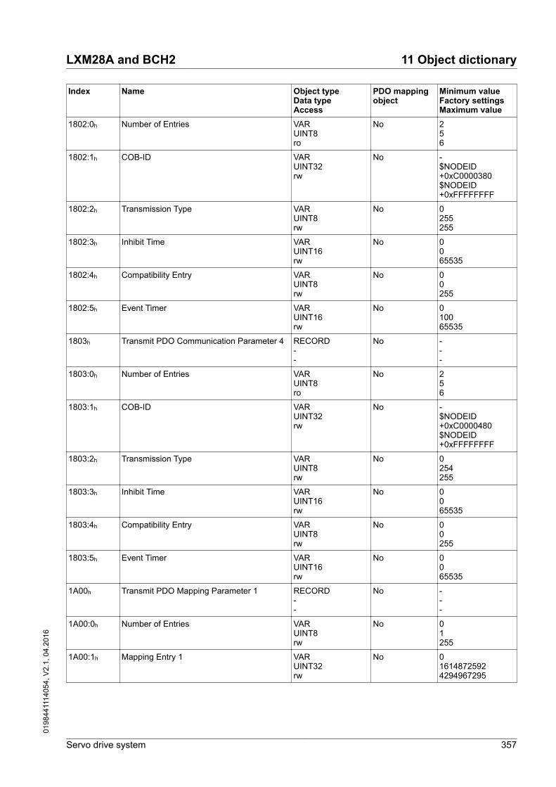
Index Name Object typeData typeAccess
PDO mappingobject
Minimum valueFactory settingsMaximum value
1802:0h Number of Entries VARUINT8ro
No 256
1802:1h COB-ID VARUINT32rw
No -$NODEID+0xC0000380$NODEID+0xFFFFFFFF
1802:2h Transmission Type VARUINT8rw
No 0255255
1802:3h Inhibit Time VARUINT16rw
No 0065535
1802:4h Compatibility Entry VARUINT8rw
No 00255
1802:5h Event Timer VARUINT16rw
No 010065535
1803h Transmit PDO Communication Parameter 4 RECORD--
No ---
1803:0h Number of Entries VARUINT8ro
No 256
1803:1h COB-ID VARUINT32rw
No -$NODEID+0xC0000480$NODEID+0xFFFFFFFF
1803:2h Transmission Type VARUINT8rw
No 0254255
1803:3h Inhibit Time VARUINT16rw
No 0065535
1803:4h Compatibility Entry VARUINT8rw
No 00255
1803:5h Event Timer VARUINT16rw
No 0065535
1A00h Transmit PDO Mapping Parameter 1 RECORD--
No ---
1A00:0h Number of Entries VARUINT8rw
No 01255
1A00:1h Mapping Entry 1 VARUINT32rw
No 016148725924294967295
LXM28A and BCH2 11 Object dictionary
Servo drive system 357
0198
4411
1405
4, V
2.1,
04.
2016

Index Name Object typeData typeAccess
PDO mappingobject
Minimum valueFactory settingsMaximum value
1A00:2h Mapping Entry 2 VARUINT32rw
No 004294967295
1A00:3h Mapping Entry 3 VARUINT32rw
No 004294967295
1A00:4h Mapping Entry 4 VARUINT32rw
No 004294967295
1A01h Transmit PDO Mapping Parameter 2 RECORD--
No ---
1A01:0h Number of Entries VARUINT8rw
No 02255
1A01:1h Mapping Entry 1 VARUINT32rw
No 016148725924294967295
1A01:2h Mapping Entry 2 VARUINT32rw
No 016171663684294967295
1A01:3h Mapping Entry 3 VARUINT32rw
No 004294967295
1A01:4h Mapping Entry 4 VARUINT32rw
No 004294967295
1A02h Transmit PDO Mapping Parameter 3 RECORD--
No ---
1A02:0h Number of Entries VARUINT8rw
No 02255
1A02:1h Mapping Entry 1 VARUINT32rw
No 016148725924294967295
1A02:2h Mapping Entry 2 VARUINT32rw
No 016176906564294967295
1A02:3h Mapping Entry 3 VARUINT32rw
No 004294967295
1A02:4h Mapping Entry 4 VARUINT32rw
No 004294967295
1A03h Transmit PDO Mapping Parameter 4 RECORD--
No ---
1A03:0h Number of Entries VARUINT8rw
No 00255
1A03:1h Mapping Entry 1 VARUINT32rw
No 004294967295
11 Object dictionary LXM28A and BCH2
358 Servo drive system
0198
4411
1405
4, V
2.1,
04.
2016

Index Name Object typeData typeAccess
PDO mappingobject
Minimum valueFactory settingsMaximum value
1A03:2h Mapping Entry 2 VARUINT32rw
No 004294967295
1A03:3h Mapping Entry 3 VARUINT32rw
No 004294967295
1A03:4h Mapping Entry 4 VARUINT32rw
No 004294967295
LXM28A and BCH2 11 Object dictionary
Servo drive system 359
0198
4411
1405
4, V
2.1,
04.
2016

11.3 Overview of the vendor-specific object group 4000h
Index Name Parameter Object typeData typeAccess
PDO mappingobject
Minimum valueFactory settingsMaximum value
4000h Firmware Version P0-00 VARUINT16ro
No 0-65535
4001h Error code of detected error P0-01 VARUINT16rw
No 0-65535
4002h Drive Status Displayed by HMI P0-02 VARUINT16rw
No 00123
4003h Function of Analog Outputs P0-03 VARUINT16rw
No 00119
4008h Operating Hour Meter in Sec-onds
P0-08 VARUINT32ro
No 0-4294967295
4009h Status Value 1 P0-09 VARINT32ro
No -2147483647-2147483647
400Ah Status Value 2 P0-10 VARINT32ro
No -2147483647-2147483647
400Bh Status Value 3 P0-11 VARINT32ro
No -2147483647-2147483647
400Ch Status Value 4 P0-12 VARINT32ro
No -2147483647-2147483647
400Dh Status Value 5 P0-13 VARINT32ro
No -2147483647-2147483647
4011h Indicate status value 1 P0-17 VARUINT16rw
No 00123
4012h Indicate status value 2 P0-18 VARUINT16rw
No 00123
4013h Indicate status value 3 P0-19 VARUINT16rw
No 00123
4014h Indicate status value 4 P0-20 VARUINT16rw
No 00123
4015h Indicate status value 5 P0-21 VARUINT16rw
No 00123
4019h Parameter Mapping 1 P0-25 VARUINT32rw
No 0-4294967295
401Ah Parameter Mapping 2 P0-26 VARUINT32rw
No 0-4294967295
11 Object dictionary LXM28A and BCH2
360 Servo drive system
0198
4411
1405
4, V
2.1,
04.
2016

Index Name Parameter Object typeData typeAccess
PDO mappingobject
Minimum valueFactory settingsMaximum value
401Bh Parameter Mapping 3 P0-27 VARUINT32rw
No 0-4294967295
401Ch Parameter Mapping 4 P0-28 VARUINT32rw
No 0-4294967295
401Dh Parameter Mapping 5 P0-29 VARUINT32rw
No 0-4294967295
401Eh Parameter Mapping 6 P0-30 VARUINT32rw
No 0-4294967295
401Fh Parameter Mapping 7 P0-31 VARUINT32rw
No 0-4294967295
4020h Parameter Mapping 8 P0-32 VARUINT32rw
No 0-4294967295
4023h Block Data Read/WriteP0-35…P0-42 1
P0-35 VARUINT32rw
No 004294967295
4024h Block Data Read/WriteP0-35…P0-42 2
P0-36 VARUINT32rw
No 004294967295
4025h Block Data Read/WriteP0-35…P0-42 3
P0-37 VARUINT32rw
No 004294967295
4026h Block Data Read/WriteP0-35…P0-42 4
P0-38 VARUINT32rw
No 004294967295
4027h Block Data Read/WriteP0-35…P0-42 5
P0-39 VARUINT32rw
No 004294967295
4028h Block Data Read/WriteP0-35…P0-42 6
P0-40 VARUINT32rw
No 004294967295
4029h Block Data Read/WriteP0-35…P0-42 7
P0-41 VARUINT32rw
No 004294967295
402Ah Block Data Read/WriteP0-35…P0-42 8
P0-42 VARUINT32rw
No 004294967295
402Eh State of Digital Outputs P0-46 VARUINT16ro
No 0-65535
402Fh Number of Last Alert P0-47 VARUINT16ro
No 0-65535
4100h Reference Value Signal -Pulse Settings
P1-00 VARUINT16rw
No 024402
4101h Operating Mode and Directionof Rotation
P1-01 VARUINT16rw
No 0114363
LXM28A and BCH2 11 Object dictionary
Servo drive system 361
0198
4411
1405
4, V
2.1,
04.
2016

Index Name Parameter Object typeData typeAccess
PDO mappingobject
Minimum valueFactory settingsMaximum value
4102h Velocity and Torque Limita-tions Activation/Deactivation
P1-02 VARUINT16rw
No 0017
4103h Polarity of Analog Outputs /Polarity of Pulse Outputs
P1-03 VARUINT16rw
No 0019
4104h Scaling Factor Analog Output1
P1-04 VARUINT16rw
No 1100100
4105h Scaling Factor Analog Output2
P1-05 VARUINT16rw
No 1100100
4109h Target Velocity/Velocity Limita-tion 1
P1-09 VARINT32rw
No -600001000060000
410Ah Target Velocity/Velocity Limita-tion 2
P1-10 VARINT32rw
No -600002000060000
410Bh Target Velocity/Velocity Limita-tion 3
P1-11 VARINT32rw
No -600003000060000
410Ch Target Torque/Torque Limita-tion 1
P1-12 VARINT16rw
No -300100300
410Dh Target Torque/Torque Limita-tion 2
P1-13 VARINT16rw
No -300100300
410Eh Target Torque/Torque Limita-tion 3
P1-14 VARINT16rw
No -300100300
410Fh Mains Phase Monitoring -Response to Missing MainsPhase
P1-15 VARUINT16rw
No 002
4110h Mains Phase Monitoring -Fault Reset
P1-16 VARUINT16rw
No 001
4111h Mains Phase Monitoring -Type
P1-17 VARUINT16rw
No 002
4112h Reserved P1-18 VARUINT16rw
No 035
4113h Active Disable - Delay TimePower Stage
P1-19 VARUINT16rw
No 006500
4114h Current Limit During QuickStop
P1-20 VARINT16rw
No 110001000
4115h Status of Foldback CurrentDrive
P1-21 VARUINT16ro
No 0-1
4116h Foldback Current Limit - Drive P1-22 VARUINT32ro
No 0-30000
11 Object dictionary LXM28A and BCH2
362 Servo drive system
0198
4411
1405
4, V
2.1,
04.
2016
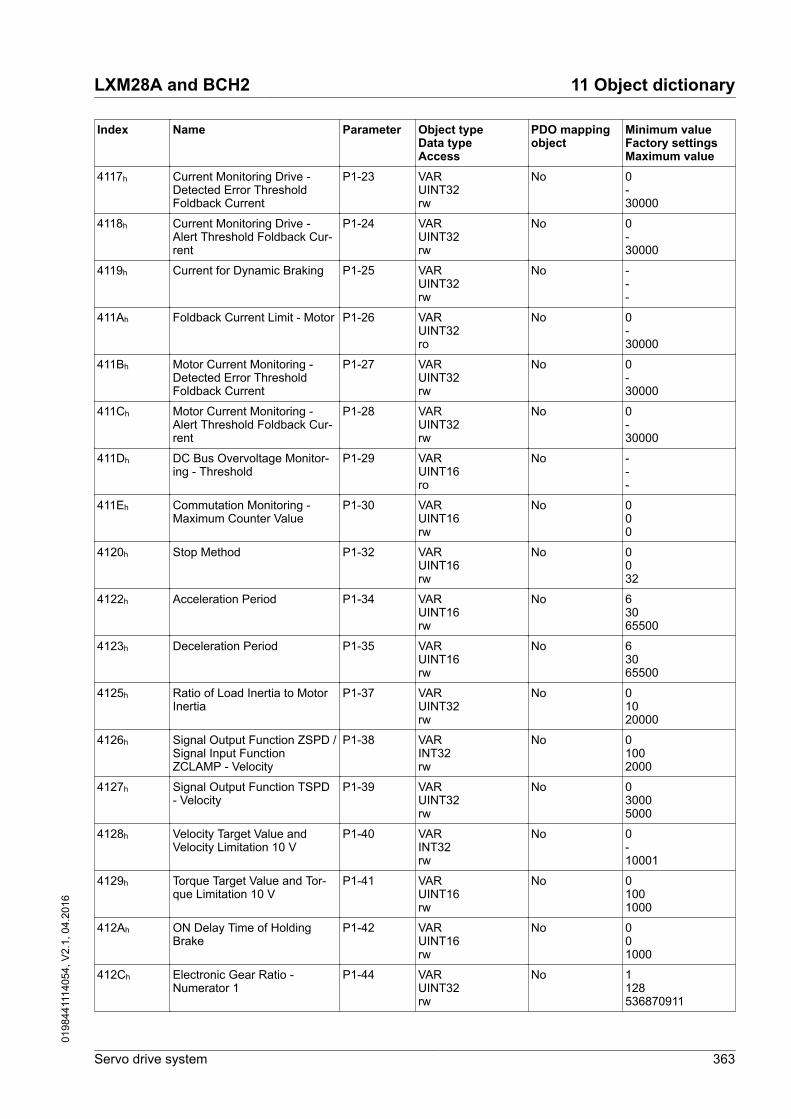
Index Name Parameter Object typeData typeAccess
PDO mappingobject
Minimum valueFactory settingsMaximum value
4117h Current Monitoring Drive -Detected Error ThresholdFoldback Current
P1-23 VARUINT32rw
No 0-30000
4118h Current Monitoring Drive -Alert Threshold Foldback Cur-rent
P1-24 VARUINT32rw
No 0-30000
4119h Current for Dynamic Braking P1-25 VARUINT32rw
No ---
411Ah Foldback Current Limit - Motor P1-26 VARUINT32ro
No 0-30000
411Bh Motor Current Monitoring -Detected Error ThresholdFoldback Current
P1-27 VARUINT32rw
No 0-30000
411Ch Motor Current Monitoring -Alert Threshold Foldback Cur-rent
P1-28 VARUINT32rw
No 0-30000
411Dh DC Bus Overvoltage Monitor-ing - Threshold
P1-29 VARUINT16ro
No ---
411Eh Commutation Monitoring -Maximum Counter Value
P1-30 VARUINT16rw
No 000
4120h Stop Method P1-32 VARUINT16rw
No 0032
4122h Acceleration Period P1-34 VARUINT16rw
No 63065500
4123h Deceleration Period P1-35 VARUINT16rw
No 63065500
4125h Ratio of Load Inertia to MotorInertia
P1-37 VARUINT32rw
No 01020000
4126h Signal Output Function ZSPD /Signal Input FunctionZCLAMP - Velocity
P1-38 VARINT32rw
No 01002000
4127h Signal Output Function TSPD- Velocity
P1-39 VARUINT32rw
No 030005000
4128h Velocity Target Value andVelocity Limitation 10 V
P1-40 VARINT32rw
No 0-10001
4129h Torque Target Value and Tor-que Limitation 10 V
P1-41 VARUINT16rw
No 01001000
412Ah ON Delay Time of HoldingBrake
P1-42 VARUINT16rw
No 001000
412Ch Electronic Gear Ratio -Numerator 1
P1-44 VARUINT32rw
No 1128536870911
LXM28A and BCH2 11 Object dictionary
Servo drive system 363
0198
4411
1405
4, V
2.1,
04.
2016

Index Name Parameter Object typeData typeAccess
PDO mappingobject
Minimum valueFactory settingsMaximum value
412Dh Electronic Gear Ratio -Denominator
P1-45 VARUINT32rw
No 1102147483647
412Eh Encoder Simulation Resolution P1-46 VARINT32rw
No -2048-
412Fh Signal Output FunctionSP_OK - Velocity
P1-47 VARUINT32rw
No 010300
4130h Signal Output FunctionMC_OK - Settings
P1-48 VARUINT16rw
No 0033
4134h Braking Resistor - Resistance P1-52 VARINT16rw
No -1-32767
4135h Braking Resistor - Power P1-53 VARINT16rw
No -1-32767
4136h Signal Output Function TPOS- Trigger Value
P1-54 VARUINT32rw
No 0128001280000
4137h Maximum Velocity - User-Defined
P1-55 VARUINT32rw
No 10-6000
4139h Torque Monitoring - TorqueValue
P1-57 VARUINT16rw
No 00300
413Ah Torque Monitoring - TimeValue
P1-58 VARUINT16rw
No 111000
413Bh S Curve Filter for OperatingMode Velocity
P1-59 VARUINT32rw
No 00255875
413Ch Commutation Monitoring -Time Threshold
P1-60 VARUINT16rw
No 003000
413Dh Commutation Monitoring -Velocity Threshold
P1-61 VARUINT32rw
No 060060000
413Eh Motor Overtemperature Moni-toring - Response
P1-62 VARUINT16rw
No 005
413Fh Motor Overtemperature Moni-toring - Delay Time
P1-63 VARUINT16rw
No 030300
4140h Undervoltage Monitoring -Response
P1-64 VARUINT16rw
No 003
4141h Reserved P1-65 VARUINT16rw
No 001
4142h Status of Foldback CurrentMotor
P1-66 VARUINT16ro
No 0-1
11 Object dictionary LXM28A and BCH2
364 Servo drive system
0198
4411
1405
4, V
2.1,
04.
2016

Index Name Parameter Object typeData typeAccess
PDO mappingobject
Minimum valueFactory settingsMaximum value
4143h Undervoltage Monitoring -Delay Time
P1-67 VARUINT16rw
No 030300
4144h Active Disable - DecelerationRamp
P1-68 VARUINT16rw
No 620065500
4145h Disable - Deceleration Time P1-69 VARUINT16rw
No 006500
4146h Signal Input Function HALT -Maximum Current
P1-70 VARUINT32rw
No -0-
4147h Braking Resistor - MaximumTime in Braking
P1-71 VARUINT16rw
No 1040100
4148h Braking Resistor OverloadMonitoring - Response
P1-72 VARUINT16rw
No 001
414Eh User-Defined Maximum Cur-rent
P1-78 VARUINT32rw
No ---
414Fh Maximum Current P1-79 VARUINT32ro
No ---
4150h Maximum Peak Current P1-80 VARUINT32ro
No ---
4151h Nominal Current P1-81 VARUINT32ro
No ---
4152h Velocity limitation for CAN-open operating mode ProfileTorque
P1-82 VARUINT16rw
No 003
4153h Change of operating modeduring movement
P1-83 VARUINT16rw
No 001
4154h Configured motor type P1-84 VARUINT32ro
No ---
4201h Gain Switching - Rate for Posi-tion Loop
P2-01 VARUINT16rw
No 10100500
4205h Gain Switching - Rate forVelocity Loop
P2-05 VARUINT16rw
No 10100500
4208h Factory Reset / Save Parame-ters / Activation of Forcing ofOutputs
P2-08 VARUINT16rw
No 00406
4209h Debounce Time - Inputs P2-09 VARUINT16rw
No 0220
420Ah Signal Input Function for DI1 P2-10 VARUINT16rw
No 0256326
LXM28A and BCH2 11 Object dictionary
Servo drive system 365
0198
4411
1405
4, V
2.1,
04.
2016

Index Name Parameter Object typeData typeAccess
PDO mappingobject
Minimum valueFactory settingsMaximum value
420Bh Signal Input Function for DI2 P2-11 VARUINT16rw
No 0256326
420Ch Signal Input Function for DI3 P2-12 VARUINT16rw
No 0256326
420Dh Signal Input Function for DI4 P2-13 VARUINT16rw
No 0256326
420Eh Signal Input Function for DI5 P2-14 VARUINT16rw
No 036326
420Fh Signal Input Function for DI6 P2-15 VARUINT16rw
No 034326
4210h Signal Input Function for DI7 P2-16 VARUINT16rw
No 035326
4211h Signal Input Function for DI8 P2-17 VARUINT16rw
No 033326
4212h Signal Output Function forDO1
P2-18 VARUINT16rw
No 0257319
4213h Signal Output Function forDO2
P2-19 VARUINT16rw
No 0256319
4214h Signal Output Function forDO3
P2-20 VARUINT16rw
No 0256319
4215h Signal Output Function forDO4
P2-21 VARUINT16rw
No 0256319
4216h Signal Output Function forDO5
P2-22 VARUINT16rw
No 07319
4217h Signal Output Function forDO6(OCZ)
P2-23 VARUINT16rw
No 064319
4218h Debounce Time - Fast Inputs P2-24 VARUINT16rw
No 050100
421Bh Gain Switching - Conditionsand Type
P2-27 VARUINT16rw
No 0024
421Dh Gain Switching - ComparisonValue
P2-29 VARUINT32rw
No 012800003840000
421Eh Auxiliary Functions P2-30 VARINT16rw
No -808
421Fh Autotuning Optimization ValueThreshold
P2-31 VARUINT32rw
No 0100010000
11 Object dictionary LXM28A and BCH2
366 Servo drive system
0198
4411
1405
4, V
2.1,
04.
2016

Index Name Parameter Object typeData typeAccess
PDO mappingobject
Minimum valueFactory settingsMaximum value
4220h Autotuning P2-32 VARUINT16rw
No 0056
4222h Velocity Monitoring - Thresh-old Value
P2-34 VARUINT32rw
No 05000060000
4223h Position Deviation Monitoring -Threshold Value
P2-35 VARUINT32rw
No 1100000128000000
4224h PTI Interface Debounce Time -Pulse
P2-36 VARUINT16ro
No 030511
4225h PTI Interface Debounce Time -Direction
P2-37 VARUINT16ro
No 030511
4232h Signal Input FunctionCLRPOS - Trigger
P2-50 VARUINT16rw
No 001
423Ch Electronic Gear Ratio -Numerator 2
P2-60 VARUINT32rw
No 1128536870911
423Dh Electronic Gear Ratio -Numerator 3
P2-61 VARUINT32rw
No 1128536870911
423Eh Electronic Gear Ratio -Numerator 4
P2-62 VARUINT32rw
No 1128536870911
4241h Special Function 1 P2-65 VARUINT16rw
No 051215936
4242h Special Function 2 P2-66 VARUINT16rw
No 004
4244h Auto-Enable and AutomaticHardware Limit Switch FaultReset
P2-68 VARUINT16rw
No 00273
4300h Device Address Modbus P3-00 VARUINT16rw
No 1127247
4301h Transmission Rate for CAN-open and Modbus
P3-01 VARUINT16rw
No 02581029
4302h Modbus Connection Settings P3-02 VARUINT16rw
No 679
4303h Detected Modbus Communi-cation Errors - Handling
P3-03 VARUINT16rw
No 001
4304h Modbus Connection Monitor-ing
P3-04 VARUINT16rw
No 0020000
4305h Device Address CANopen P3-05 VARUINT16rw
No 00127
LXM28A and BCH2 11 Object dictionary
Servo drive system 367
0198
4411
1405
4, V
2.1,
04.
2016

Index Name Parameter Object typeData typeAccess
PDO mappingobject
Minimum valueFactory settingsMaximum value
4306h Digital Inputs - Forcing Set-tings
P3-06 VARUINT16rw
No 002047
4307h Modbus Response Delay Time P3-07 VARUINT16rw
No 001000
4309h CANopen Master/Slave Syn-chronization
P3-09 VARUINT16rw
No 40972056540959
430Ah Drive Profile Lexium - Activa-tion
P3-10 VARUINT16rw
No 001
430Bh Drive Profile Lexium - State ofDigital Inputs
P3-11 VARUINT16ro
Yes 0-65535
430Ch Drive Profile Lexium - ControlWord
P3-12 VARUINT16rww
Yes 0065535
430Dh Drive Profile Lexium - RefA 16Bit Parameter
P3-13 VARINT16rww
Yes -32768032767
430Eh Drive Profile Lexium - RefB 32Bit Parameter
P3-14 VARINT32rww
Yes -214748364802147483647
430Fh Drive Profile Lexium - DriveStatus
P3-15 VARUINT16ro
Yes 0-65535
4310h Drive Profile Lexium - Operat-ing Mode Status
P3-16 VARUINT16ro
Yes 0-65535
4311h Drive Profile Lexium - MotionStatus
P3-17 VARUINT16ro
Yes 0-65535
4312h PDO Event Mask 1 P3-18 VARUINT16rw
No 0115
4313h PDO Event Mask 2 P3-19 VARUINT16rw
No 0115
4314h PDO Event Mask 3 P3-20 VARUINT16rw
No 0115
4315h PDO Event Mask 4 P3-21 VARUINT16rw
No 01515
431Eh Internal Limit for Bit 11 Drive-Com Status Word 6041
P3-30 VARUINT16rw
No 0011
431Fh Settings for NMT operatingstate Quick Stop
P3-31 VARUINT16rw
No 667
4320h Automatic operating state tran-sition from Switch On Disabledto Ready To Switch On
P3-32 VARUINT16rw
No 001
11 Object dictionary LXM28A and BCH2
368 Servo drive system
0198
4411
1405
4, V
2.1,
04.
2016

Index Name Parameter Object typeData typeAccess
PDO mappingobject
Minimum valueFactory settingsMaximum value
4328h Velocity Window - VARUINT32rw
No 021000004294967295
4329h Velocity Threshold - VARUINT32rw
No 021000004294967295
4400h Error History - Number of MostRecent Detected Error n
P4-00 VARUINT16rw
No 0-0
4401h Error History - Number of MostRecent Detected Error n - 1
P4-01 VARUINT16ro
No 0-0
4402h Error History - Number of MostRecent Detected Error n - 2
P4-02 VARUINT16ro
No 0-0
4403h Error History - Number of MostRecent Detected Error n - 3
P4-03 VARUINT16ro
No 0-0
4404h Error History - Number of MostRecent Detected Error n - 4
P4-04 VARUINT16ro
No 0-0
4405h Jog Velocity P4-05 VARUINT32rw
No 0205000
4406h Setting a signal output viaparameter
P4-06 VARUINT16rw
No 00255
4407h State of Digital Inputs / Acti-vate Forcing
P4-07 VARUINT16rw
No 0-255
4408h Status of HMI Keypad P4-08 VARUINT16ro
No 00255
4409h State of Digital Outputs P4-09 VARUINT16ro
No 0-63
440Ah Clear Error History P4-10 VARUINT16rw
No 000
4416h Analog Input 1 Offset P4-22 VARINT16rw
No -10000010000
4417h Analog Input 2 Offset P4-23 VARINT16rw
No -10000010000
4418h Undervoltage Monitoring -Threshold Value
P4-24 VARUINT16rw
No 140160190
4419h Safety Function STO - Status P4-25 VARUINT16ro
No 0-1
441Ah Digital Outputs - Forcing Infor-mation
P4-26 VARUINT16ro
No 0-31
LXM28A and BCH2 11 Object dictionary
Servo drive system 369
0198
4411
1405
4, V
2.1,
04.
2016

Index Name Parameter Object typeData typeAccess
PDO mappingobject
Minimum valueFactory settingsMaximum value
441Bh Digital Outputs - Forcing Set-tings
P4-27 VARUINT16rw
No 0031
441Ch State of Digital Outputs / Acti-vate Forcing
P4-28 VARUINT16rw
No 0031
4450h Jog Speed Fast - VARUINT32rw
No 04266744294967295
4451h Jog Time - VARUINT32rw
No 004294967295
4452h Jog Step - VARUINT32rw
No 002147483647
4453h Jog Method - VARUINT16rw
No 001
4454h Jog Speed Slow - VARUINT32rw
No 04266744294967295
4500h Firmware Revision P5-00 VARUINT16ro
No 0-65535
4504h Homing - Homing MethodSelection
P5-04 VARUINT16rw
No 00296
4505h Homing - Fast Velocity for Ref-erence Movement
P5-05 VARUINT32rw
No 10100060000
4506h Homing - Slow Velocity forReference Movement
P5-06 VARUINT32rw
No 1020060000
4507h Operating Mode PS viaParameter
P5-07 VARUINT16rw
No 001000
4508h Positive Software Limit Switch- Position
P5-08 VARINT32rw
No -21474836471342177272147483647
4509h Negative Software LimitSwitch - Position
P5-09 VARINT32rw
No -2147483647-1342177272147483647
450Ah Operating mode Pulse Train -Maximum Acceleration
P5-10 VARUINT16rw
No 6665500
450Bh Software Limit Switches - Hys-teresis Value
P5-11 VARUINT16rw
No 0355635555
450Ch Touch Probe Input 1 - StableLevel Duration
P5-12 VARUINT16rw
No 2532
450Dh Software Limit Switches - Acti-vation
P5-13 VARUINT16rw
No 001
11 Object dictionary LXM28A and BCH2
370 Servo drive system
0198
4411
1405
4, V
2.1,
04.
2016

Index Name Parameter Object typeData typeAccess
PDO mappingobject
Minimum valueFactory settingsMaximum value
450Eh Motion Profile for Torque -Slope
P5-14 VARUINT32rw
No 110000030000000
450Fh Motion Profile for Torque -Activation
P5-15 VARUINT16rw
No 001
4510h Encoder Increments in PUU P5-16 VARINT32rw
No -214748364702147483647
4512h External Encoder (Pulses) P5-18 VARINT32ro
No -2147483648-2147483647
4514h Deceleration Ramp - SignalInput Function STOP
P5-20 VARUINT16rw
No 65065500
4515h Deceleration Ramp - DetectedTransmission Error
P5-21 VARUINT16rw
No 65065500
4516h Deceleration Ramp - PositionOverflow
P5-22 VARUINT16rw
No 63065500
4517h Deceleration Ramp - Trigger-ing of Negative Software LimitSwitch
P5-23 VARUINT16rw
No 65065500
4518h Deceleration Ramp - Trigger-ing of Positive Software LimitSwitch
P5-24 VARUINT16rw
No 65065500
4519h Deceleration Ramp - Trigger-ing of Negative Hardware LimitSwitch
P5-25 VARUINT16rw
No 63065500
451Ah Deceleration Ramp - Trigger-ing of Positive Hardware LimitSwitch
P5-26 VARUINT16rw
No 63065500
4525h Touch Probe Input 1 - Cap-tured Position
P5-37 VARINT32ro
No -214748364702147483647
4526h Touch Probe Input 1 - EventCounter
P5-38 VARUINT16ro
No 0065535
4527h Touch Probe Input 1 - Configu-ration
P5-39 VARUINT16rw
No 00257
4539h Touch Probe Input 2 - Cap-tured Position
P5-57 VARINT32ro
No -214748364702147483647
453Ah Touch Probe Input 2 - EventCounter
P5-58 VARUINT16ro
No 0065535
453Bh Touch Probe Input 2 - Configu-ration
P5-59 VARUINT16rw
No 00257
454Dh Touch Probe Input 2 - StableLevel Duration
P5-77 VARUINT16rw
No 2532
LXM28A and BCH2 11 Object dictionary
Servo drive system 371
0198
4411
1405
4, V
2.1,
04.
2016

Index Name Parameter Object typeData typeAccess
PDO mappingobject
Minimum valueFactory settingsMaximum value
4600h Position of Homing Data Set P6-00 VARINT32rw
No -214748364702147483647
4601h Subsequent Data Set andAuto-start of Homing Data Set
P6-01 VARUINT32rw
No 008193
4602h Target Position of Data Set 1 P6-02 VARINT32rw
No -214748364702147483647
4603h Configuration of Data Set 1 P6-03 VARUINT16rw
No 00144
4604h Target Position of Data Set 2 P6-04 VARINT32rw
No -214748364702147483647
4605h Configuration of Data Set 2 P6-05 VARUINT16rw
No 00144
4606h Target Position of Data Set 3 P6-06 VARINT32rw
No -214748364702147483647
4607h Configuration of Data Set 3 P6-07 VARUINT16rw
No 00144
4608h Target Position of Data Set 4 P6-08 VARINT32rw
No -214748364702147483647
4609h Configuration of Data Set 4 P6-09 VARUINT16rw
No 00144
460Ah Target Position of Data Set 5 P6-10 VARINT32rw
No -214748364702147483647
460Bh Configuration of Data Set 5 P6-11 VARUINT16rw
No 00144
460Ch Target Position of Data Set 6 P6-12 VARINT32rw
No -214748364702147483647
460Dh Configuration of Data Set 6 P6-13 VARUINT16rw
No 00144
460Eh Target Position of Data Set 7 P6-14 VARINT32rw
No -214748364702147483647
460Fh Configuration of Data Set 7 P6-15 VARUINT16rw
No 00144
4610h Target Position of Data Set 8 P6-16 VARINT32rw
No -214748364702147483647
4611h Configuration of Data Set 8 P6-17 VARUINT16rw
No 00144
11 Object dictionary LXM28A and BCH2
372 Servo drive system
0198
4411
1405
4, V
2.1,
04.
2016

Index Name Parameter Object typeData typeAccess
PDO mappingobject
Minimum valueFactory settingsMaximum value
4612h Target Position of Data Set 9 P6-18 VARINT32rw
No -214748364702147483647
4613h Configuration of Data Set 9 P6-19 VARUINT16rw
No 00144
4614h Target Position of Data Set 10 P6-20 VARINT32rw
No -214748364702147483647
4615h Configuration of Data Set 10 P6-21 VARUINT16rw
No 00144
4616h Target Position of Data Set 11 P6-22 VARINT32rw
No -214748364702147483647
4617h Configuration of Data Set 11 P6-23 VARUINT16rw
No 00144
4618h Target Position of Data Set 12 P6-24 VARINT32rw
No -214748364702147483647
4619h Configuration of Data Set 12 P6-25 VARUINT16rw
No 00144
461Ah Target Position of Data Set 13 P6-26 VARINT32rw
No -214748364702147483647
461Bh Configuration of Data Set 13 P6-27 VARUINT16rw
No 00144
461Ch Target Position of Data Set 14 P6-28 VARINT32rw
No -214748364702147483647
461Dh Configuration of Data Set 14 P6-29 VARUINT16rw
No 00144
461Eh Target Position of Data Set 15 P6-30 VARINT32rw
No -214748364702147483647
461Fh Configuration of Data Set 15 P6-31 VARUINT16rw
No 00144
4620h Target Position of Data Set 16 P6-32 VARINT32rw
No -214748364702147483647
4621h Configuration of Data Set 16 P6-33 VARUINT16rw
No 00144
4622h Target Position of Data Set 17 P6-34 VARINT32rw
No -214748364702147483647
4623h Configuration of Data Set 17 P6-35 VARUINT16rw
No 00144
LXM28A and BCH2 11 Object dictionary
Servo drive system 373
0198
4411
1405
4, V
2.1,
04.
2016

Index Name Parameter Object typeData typeAccess
PDO mappingobject
Minimum valueFactory settingsMaximum value
4624h Target Position of Data Set 18 P6-36 VARINT32rw
No -214748364702147483647
4625h Configuration of Data Set 18 P6-37 VARUINT16rw
No 00144
4626h Target Position of Data Set 19 P6-38 VARINT32rw
No -214748364702147483647
4627h Configuration of Data Set 19 P6-39 VARUINT16rw
No 00144
4628h Target Position of Data Set 20 P6-40 VARINT32rw
No -214748364702147483647
4629h Configuration of Data Set 20 P6-41 VARUINT16rw
No 00144
462Ah Target Position of Data Set 21 P6-42 VARINT32rw
No -214748364702147483647
462Bh Configuration of Data Set 21 P6-43 VARUINT16rw
No 00144
462Ch Target Position of Data Set 22 P6-44 VARINT32rw
No -214748364702147483647
462Dh Configuration of Data Set 22 P6-45 VARUINT16rw
No 00144
462Eh Target Position of Data Set 23 P6-46 VARINT32rw
No -214748364702147483647
462Fh Configuration of Data Set 23 P6-47 VARUINT16rw
No 00144
4630h Target Position of Data Set 24 P6-48 VARINT32rw
No -214748364702147483647
4631h Configuration of Data Set 24 P6-49 VARUINT16rw
No 00144
4632h Target Position of Data Set 25 P6-50 VARINT32rw
No -214748364702147483647
4633h Configuration of Data Set 25 P6-51 VARUINT16rw
No 00144
4634h Target Position of Data Set 26 P6-52 VARINT32rw
No -214748364702147483647
4635h Configuration of Data Set 26 P6-53 VARUINT16rw
No 00144
11 Object dictionary LXM28A and BCH2
374 Servo drive system
0198
4411
1405
4, V
2.1,
04.
2016

Index Name Parameter Object typeData typeAccess
PDO mappingobject
Minimum valueFactory settingsMaximum value
4636h Target Position of Data Set 27 P6-54 VARINT32rw
No -214748364702147483647
4637h Configuration of Data Set 27 P6-55 VARUINT16rw
No 00144
4638h Target Position of Data Set 28 P6-56 VARINT32rw
No -214748364702147483647
4639h Configuration of Data Set 28 P6-57 VARUINT16rw
No 00144
463Ah Target Position of Data Set 29 P6-58 VARINT32rw
No -214748364702147483647
463Bh Configuration of Data Set 29 P6-59 VARUINT16rw
No 00144
463Ch Target Position of Data Set 30 P6-60 VARINT32rw
No -214748364702147483647
463Dh Configuration of Data Set 30 P6-61 VARUINT16rw
No 00144
463Eh Target Position of Data Set 31 P6-62 VARINT32rw
No -214748364702147483647
463Fh Configuration of Data Set 31 P6-63 VARUINT16rw
No 00144
4640h Target Position of Data Set 32 P6-64 VARINT32rw
No -214748364702147483647
4641h Configuration of Data Set 32 P6-65 VARUINT16rw
No 00144
4700h Deceleration and Accelerationof Homing Data Set
P7-00 VARUINT32rw
No 393222131074004292673500
4701h Waiting Time of Homing DataSet
P7-01 VARUINT32rw
No 0032767
4702h Deceleration and Accelerationof Data Set 1
P7-02 VARUINT32rw
No 393222131074004292673500
4703h Waiting Time and TargetVelocity of Data Set 1
P7-03 VARUINT32rw
No 0131072003932192767
4704h Deceleration and Accelerationof Data Set 2
P7-04 VARUINT32rw
No 393222131074004292673500
4705h Waiting Time and TargetVelocity of Data Set 2
P7-05 VARUINT32rw
No 0131072003932192767
LXM28A and BCH2 11 Object dictionary
Servo drive system 375
0198
4411
1405
4, V
2.1,
04.
2016

Index Name Parameter Object typeData typeAccess
PDO mappingobject
Minimum valueFactory settingsMaximum value
4706h Deceleration and Accelerationof Data Set 3
P7-06 VARUINT32rw
No 393222131074004292673500
4707h Waiting Time and TargetVelocity of Data Set 3
P7-07 VARUINT32rw
No 0131072003932192767
4708h Deceleration and Accelerationof Data Set 4
P7-08 VARUINT32rw
No 393222131074004292673500
4709h Waiting Time and TargetVelocity of Data Set 4
P7-09 VARUINT32rw
No 0131072003932192767
470Ah Deceleration and Accelerationof Data Set 5
P7-10 VARUINT32rw
No 393222131074004292673500
470Bh Waiting Time and TargetVelocity of Data Set 5
P7-11 VARUINT32rw
No 0131072003932192767
470Ch Deceleration and Accelerationof Data Set 6
P7-12 VARUINT32rw
No 393222131074004292673500
470Dh Waiting Time and TargetVelocity of Data Set 6
P7-13 VARUINT32rw
No 0131072003932192767
470Eh Deceleration and Accelerationof Data Set 7
P7-14 VARUINT32rw
No 393222131074004292673500
470Fh Waiting Time and TargetVelocity of Data Set 7
P7-15 VARUINT32rw
No 0131072003932192767
4710h Deceleration and Accelerationof Data Set 8
P7-16 VARUINT32rw
No 393222131074004292673500
4711h Waiting Time and TargetVelocity of Data Set 8
P7-17 VARUINT32rw
No 0131072003932192767
4712h Deceleration and Accelerationof Data Set 9
P7-18 VARUINT32rw
No 393222131074004292673500
4713h Waiting Time and TargetVelocity of Data Set 9
P7-19 VARUINT32rw
No 0131072003932192767
4714h Deceleration and Accelerationof Data Set 10
P7-20 VARUINT32rw
No 393222131074004292673500
4715h Waiting Time and TargetVelocity of Data Set 10
P7-21 VARUINT32rw
No 0131072003932192767
4716h Deceleration and Accelerationof Data Set 11
P7-22 VARUINT32rw
No 393222131074004292673500
4717h Waiting Time and TargetVelocity of Data Set 11
P7-23 VARUINT32rw
No 0131072003932192767
11 Object dictionary LXM28A and BCH2
376 Servo drive system
0198
4411
1405
4, V
2.1,
04.
2016

Index Name Parameter Object typeData typeAccess
PDO mappingobject
Minimum valueFactory settingsMaximum value
4718h Deceleration and Accelerationof Data Set 12
P7-24 VARUINT32rw
No 393222131074004292673500
4719h Waiting Time and TargetVelocity of Data Set 12
P7-25 VARUINT32rw
No 0131072003932192767
471Ah Deceleration and Accelerationof Data Set 13
P7-26 VARUINT32rw
No 393222131074004292673500
471Bh Waiting Time and TargetVelocity of Data Set 13
P7-27 VARUINT32rw
No 0131072003932192767
471Ch Deceleration and Accelerationof Data Set 14
P7-28 VARUINT32rw
No 393222131074004292673500
471Dh Waiting Time and TargetVelocity of Data Set 14
P7-29 VARUINT32rw
No 0131072003932192767
471Eh Deceleration and Accelerationof Data Set 15
P7-30 VARUINT32rw
No 393222131074004292673500
471Fh Waiting Time and TargetVelocity of Data Set 15
P7-31 VARUINT32rw
No 0131072003932192767
4720h Deceleration and Accelerationof Data Set 16
P7-32 VARUINT32rw
No 393222131074004292673500
4721h Waiting Time and TargetVelocity of Data Set 16
P7-33 VARUINT32rw
No 0131072003932192767
4722h Deceleration and Accelerationof Data Set 17
P7-34 VARUINT32rw
No 393222131074004292673500
4723h Waiting Time and TargetVelocity of Data Set 17
P7-35 VARUINT32rw
No 0131072003932192767
4724h Deceleration and Accelerationof Data Set 18
P7-36 VARUINT32rw
No 393222131074004292673500
4725h Waiting Time and TargetVelocity of Data Set 18
P7-37 VARUINT32rw
No 0131072003932192767
4726h Deceleration and Accelerationof Data Set 19
P7-38 VARUINT32rw
No 393222131074004292673500
4727h Waiting Time and TargetVelocity of Data Set 19
P7-39 VARUINT32rw
No 0131072003932192767
4728h Deceleration and Accelerationof Data Set 20
P7-40 VARUINT32rw
No 393222131074004292673500
4729h Waiting Time and TargetVelocity of Data Set 20
P7-41 VARUINT32rw
No 0131072003932192767
LXM28A and BCH2 11 Object dictionary
Servo drive system 377
0198
4411
1405
4, V
2.1,
04.
2016

Index Name Parameter Object typeData typeAccess
PDO mappingobject
Minimum valueFactory settingsMaximum value
472Ah Deceleration and Accelerationof Data Set 21
P7-42 VARUINT32rw
No 393222131074004292673500
472Bh Waiting Time and TargetVelocity of Data Set 21
P7-43 VARUINT32rw
No 0131072003932192767
472Ch Deceleration and Accelerationof Data Set 22
P7-44 VARUINT32rw
No 393222131074004292673500
472Dh Waiting Time and TargetVelocity of Data Set 22
P7-45 VARUINT32rw
No 0131072003932192767
472Eh Deceleration and Accelerationof Data Set 23
P7-46 VARUINT32rw
No 393222131074004292673500
472Fh Waiting Time and TargetVelocity of Data Set 23
P7-47 VARUINT32rw
No 0131072003932192767
4730h Deceleration and Accelerationof Data Set 24
P7-48 VARUINT32rw
No 393222131074004292673500
4731h Waiting Time and TargetVelocity of Data Set 24
P7-49 VARUINT32rw
No 0131072003932192767
4732h Deceleration and Accelerationof Data Set 25
P7-50 VARUINT32rw
No 393222131074004292673500
4733h Waiting Time and TargetVelocity of Data Set 25
P7-51 VARUINT32rw
No 0131072003932192767
4734h Deceleration and Accelerationof Data Set 26
P7-52 VARUINT32rw
No 393222131074004292673500
4735h Waiting Time and TargetVelocity of Data Set 26
P7-53 VARUINT32rw
No 0131072003932192767
4736h Deceleration and Accelerationof Data Set 27
P7-54 VARUINT32rw
No 393222131074004292673500
4737h Waiting Time and TargetVelocity of Data Set 27
P7-55 VARUINT32rw
No 0131072003932192767
4738h Deceleration and Accelerationof Data Set 28
P7-56 VARUINT32rw
No 393222131074004292673500
4739h Waiting Time and TargetVelocity of Data Set 28
P7-57 VARUINT32rw
No 0131072003932192767
473Ah Deceleration and Accelerationof Data Set 29
P7-58 VARUINT32rw
No 393222131074004292673500
473Bh Waiting Time and TargetVelocity of Data Set 29
P7-59 VARUINT32rw
No 0131072003932192767
11 Object dictionary LXM28A and BCH2
378 Servo drive system
0198
4411
1405
4, V
2.1,
04.
2016

Index Name Parameter Object typeData typeAccess
PDO mappingobject
Minimum valueFactory settingsMaximum value
473Ch Deceleration and Accelerationof Data Set 30
P7-60 VARUINT32rw
No 393222131074004292673500
473Dh Waiting Time and TargetVelocity of Data Set 30
P7-61 VARUINT32rw
No 0131072003932192767
473Eh Deceleration and Accelerationof Data Set 31
P7-62 VARUINT32rw
No 393222131074004292673500
473Fh Waiting Time and TargetVelocity of Data Set 31
P7-63 VARUINT32rw
No 0131072003932192767
4740h Deceleration and Accelerationof Data Set 32
P7-64 VARUINT32rw
No 393222131074004292673500
4741h Waiting Time and TargetVelocity of Data Set 32
P7-65 VARUINT32rw
No 0131072003932192767
4800h Derivative Gain P8-00 VARUINT32rw
No 080020000
4801h Integral Gain P8-01 VARUINT32rw
No 01002000
4802h Derivative-Integral Gain P8-02 VARUINT32rw
No 04004000
4803h Proportional Gain P8-03 VARUINT32rw
No 03004000
4804h Global Gain P8-04 VARUINT32rw
No 1005003000
4805h HD Spring Filter P8-05 VARUINT16rw
No 1070007000
4806h Anti-Vibration Gain P8-06 VARUINT32rw
No 0010000
4807h Pe filter P8-07 VARUINT32rw
No 0099000
4808h Anti-Vibration Filter P8-08 VARUINT32rw
No 5040004000
4809h Pe filter P8-09 VARUINT32rw
No 5040004000
480Ah Ratio of Load Inertia to MotorInertia for Anti-Vibration
P8-10 VARUINT32rw
No 006000
480Bh NL Anti Resonance FilterDivider
P8-11 VARUINT32rw
No 120010000
LXM28A and BCH2 11 Object dictionary
Servo drive system 379
0198
4411
1405
4, V
2.1,
04.
2016

Index Name Parameter Object typeData typeAccess
PDO mappingobject
Minimum valueFactory settingsMaximum value
480Ch Anti-Resonance Sharpness P8-12 VARUINT16rw
No 1050010000
480Dh Pe Sharpness P8-13 VARUINT16rw
No 1050010000
480Eh Current Filter Damping P8-14 VARUINT16rw
No 00100
480Fh Current Filter Low Pass FilterRise Time
P8-15 VARUINT16rw
No 03003000
4810h Current Filter - Second NotchFilter Bandwidth
P8-16 VARUINT16rw
No 00500
4811h Current Filter - Second NotchFilter Center
P8-17 VARUINT16rw
No 10010010000
4812h Current Filter - Notch FilterBandwidth
P8-18 VARUINT16rw
No 00500
4813h Current Filter - Notch FilterCenter
P8-19 VARUINT16rw
No 10010010000
4814h Elasticity Compensation P8-20 VARUINT32rw
No 05000050000
4815h Spring Deceleration Ratio P8-21 VARUINT16rw
No 010002000
4816h Analog NCT standstill P8-22 VARINT16rw
No -381503815
4817h Analog Input 1 Filter P8-23 VARUINT16rw
No 10100010000
4818h Analog Input 2 - Filter P8-24 VARUINT16rw
No 10100010000
4819h Electronic Gear Filter - Accel-eration Feedforward
P8-25 VARINT16rw
No -200002000
481Ah Electronic Gear Filter - Activa-tion
P8-26 VARUINT16rw
No 001
481Bh Electronic Gear Filter - Depth P8-27 VARUINT32rw
No 7520010000
481Ch Electronic Gear Filter - Veloc-ity and Acceleration Depth
P8-28 VARUINT16rw
No 04006000
481Dh Electronic Gear Filter - Veloc-ity Feedforward
P8-29 VARINT32rw
No -20000020000
11 Object dictionary LXM28A and BCH2
380 Servo drive system
0198
4411
1405
4, V
2.1,
04.
2016

Index Name Parameter Object typeData typeAccess
PDO mappingobject
Minimum valueFactory settingsMaximum value
481Eh Interpolation of Input Signal forElectronic Gear - Activation
P8-30 VARUINT16rw
No 011
481Fh Method for Operating ModePulse Train (PT)
P8-31 VARUINT16rw
No 013
4820h Position Command moveaveraging number
P8-32 VARUINT32rw
No 25150025600
4821h Position Command Move LowPass Filter Via P Parameter
P8-33 VARUINT16rw
No 150005000
4822h Smoothing Filter for Operatingmodes PT and PS - Type
P8-34 VARUINT16rw
No 022
4823h Type of Velocity Control P8-35 VARUINT16rw
No 577
4824h Pe filter 3 P8-36 VARUINT32rw
No 001000000
4825h Pe filter 3 P8-37 VARUINT32rw
No 5040004000
4826h Pe filter 3 P8-38 VARUINT32rw
No 010001000000
4827h Gravity Compensation P8-39 VARINT16rw
No -0-
4828h HD AFF P8-40 VARUINT16rw
No 00200
4829h Pe Sharpness P8-41 VARUINT16rw
No 1020010000
4863h Adaptive Velocity ReferenceValue Gain
P8-99 VARUINT32rw
No 010003000
4900h Lexium program number P9-00 VARUINT32ro
No 0-4294967295
4901h Firmware Version Date P9-01 VARUINT32ro
No 0-4294967295
4906h User-Defined ApplicationName 1
P9-06 VARUINT32rw
No 004294967295
4907h User-Defined ApplicationName 2
P9-07 VARUINT32rw
No 004294967295
4908h User-Defined ApplicationName 3
P9-08 VARUINT32rw
No 004294967295
LXM28A and BCH2 11 Object dictionary
Servo drive system 381
0198
4411
1405
4, V
2.1,
04.
2016

Index Name Parameter Object typeData typeAccess
PDO mappingobject
Minimum valueFactory settingsMaximum value
4909h User-Defined ApplicationName 4
P9-09 VARUINT32rw
No 004294967295
490Ah Modbus Word Order P9-10 VARUINT16rw
No 001
490Bh Serial Number Part 1 P9-11 VARUINT32ro
No 0-4294967295
490Ch Serial Number Part 2 P9-12 VARUINT32ro
No 0-4294967295
490Dh Serial Number Part 3 P9-13 VARUINT32ro
No 0-4294967295
490Eh Serial Number Part 4 P9-14 VARUINT32ro
No 0-4294967295
490Fh Autotuning Method P9-15 VARUINT16rw
No 006
4910h Autotuning Motion Profile -Type
P9-16 VARUINT16rw
No 002
4911h Anti-vibration tuning mode. P9-17 VARUINT16rw
No 026
4912h Autotuning Results - Save/Discard
P9-18 VARUINT16rw
No 003
4913h Autotuning - Elasticity Com-pensation Filters
P9-19 VARINT16rw
No 011
4914h Autotuning - Direction ofMovement
P9-20 VARINT16rw
No 003
4915h Minimum Dwell Time forDetection of Movement Cycle
P9-21 VARUINT16rw
No 1002001000
4916h Autotuning - Automatic Esti-mation of Ratio of Load Inertiaand Motor Inertia
P9-22 VARUINT16rw
No 001
4917h Defines which values will beused for the position commandfilters.
P9-23 VARUINT16rw
No 001
4918h Torque filter tuning mode. P9-24 VARINT16rw
No 002
4919h Autotuning Motion Profile -Activation
P9-25 VARUINT16rw
No 001
491Ah Autotuning - PermissibleMovement Range in PositiveDirection
P9-26 VARINT32rw
No -214748364702147483647
11 Object dictionary LXM28A and BCH2
382 Servo drive system
0198
4411
1405
4, V
2.1,
04.
2016

Index Name Parameter Object typeData typeAccess
PDO mappingobject
Minimum valueFactory settingsMaximum value
491Bh Autotuning - PermissibleMovement Range in NegativeDirection
P9-27 VARINT32rw
No -214748364702147483647
491Ch Autotuning Active P9-28 VARINT16ro
No 0-1
491Dh Autotuning - Velocity P9-29 VARUINT32rw
No ---
491Eh Autotuning - Status P9-30 VARUINT32ro
No 0-65535
491Fh Autotuning - Acceleration andDeceleration
P9-31 VARUINT32rw
No 3932223932220004292673500
4920h Autotune advance mode. P9-32 VARUINT16rw
No 002
4921h Maximum Autotuning Optimi-zation Value
P9-33 VARUINT32ro
No 0-1000
4922h Autotuning Progress Bar P9-34 VARUINT16ro
No 00100
4923h Autotuning - Gravity Estima-tion
P9-35 VARUINT16rw
No 001
4924h Set KNLAFRC in Autotune P9-36 VARINT16rw
No 001
4925h Autotuning - Last Stored Event P9-37 VARUINT32ro
No 0065535
4A00h Login for Commissioning - VARUINT16rw
No 003
4A01h Content of HMI 1 - 4 - VARUINT32ro
No 0-4294967295
4A02h Content of HMI 5 - VARUINT32ro
No 0-255
4A03h Detected Modbus Communi-cation Error During Login
- VARUINT16rw
No 0020000
4A06h Lock for Configuration - VARUINT16rw
No 004
4A08h Save Parameters - VARUINT16rw
No 001
4A09h Reset to Factory Settings - VARUINT16rw
No 001
LXM28A and BCH2 11 Object dictionary
Servo drive system 383
0198
4411
1405
4, V
2.1,
04.
2016

Index Name Parameter Object typeData typeAccess
PDO mappingobject
Minimum valueFactory settingsMaximum value
4A0Ah Modbus - Most Recent InvalidParameter
- VARUINT16ro
No 0065535
4A0Bh Scope Command - VARUINT16rw
No 001
4A0Ch Scope - Number of Variablesto Record
- VARUINT16rw
No 004
4A0Dh Scope - Version - VARUINT16ro
No 1165535
4A0Eh Scope - Time Interval - VARUINT32rw
No 3110002147483644
4A0Fh Scope - Status - VARUINT16ro
No 0-3
4A10h Scope - Number of Points toRecord
- VARUINT16rw
No 002000
4A11h Scope - Trigger Type - VARUINT16rw
No 002
4A12h Scope - Pre-Trigger Points - VARUINT16rw
No 0065500
4A13h Scope - Trigger Value - VARINT32rw
No -214748364702147483647
4A14h Scope - Variables to Record 1 - VARUINT16rw
No 0065535
4A15h Scope - Variables to Record 2 - VARUINT16rw
No 0065535
4A16h Scope - Variables to Record 3 - VARUINT16rw
No 0065535
4A17h Scope - Variables to Record 4 - VARUINT16rw
No 0065535
4A18h Scope - Trigger Variable - VARUINT16rw
No 0065535
4A19h Jog via Modbus - VARUINT16rw
No 002
4A1Ah Number of Parameters in Sta-tus Block
- VARUINT16ro
No 202020
4A1Bh Values of Parameters in StatusBlock
- VARUINT16ro
No ---
11 Object dictionary LXM28A and BCH2
384 Servo drive system
0198
4411
1405
4, V
2.1,
04.
2016

Index Name Parameter Object typeData typeAccess
PDO mappingobject
Minimum valueFactory settingsMaximum value
4A1Ch Number of Parameters in DataBlock
- VARUINT16ro
No 272727
4A1Dh Values of Parameters in DataBlock
- VARUINT16ro
No ---
4A1Eh Access Rights - User Level - VARUINT32rw
No 014294967295
4A1Fh Access Rights - User LevelStatus
- VARUINT16ro
No 25610241024
4A20h Exclusive Access - VARUINT16rw
No 001
4A21h Internal Motion Profile - Incre-mental Movement Distance
- VARINT32rw
No -214748364702147483647
4A22h Internal Motion Profile - Veloc-ity
- VARUINT16rw
No 01000060000
4A23h Internal Motion Profile - Accel-eration/Deceleration
- VARUINT32rw
No 3932223932220004292673500
4A24h Internal Motion Profile - Trig-ger and Repetitions
- VARINT16rw
No -1032767
4A25h Access Lock - VARUINT16rw
No 001
4B00h Position - VARINT32ro
No ---
4B01h Target Position in PUU - VARINT32ro
No ---
4B02h Position Deviation in PUU - VARINT32ro
No ---
4B03h Actual Position in Pulses - VARINT32ro
No ---
4B04h Target Position in Pulses - VARINT32ro
No ---
4B05h Position Deviation in Pulses - VARINT32ro
No ---
4B06h Input Frequency - VARINT32ro
No ---
4B07h Actual Velocity in min-1 - VARINT32ro
No ---
LXM28A and BCH2 11 Object dictionary
Servo drive system 385
0198
4411
1405
4, V
2.1,
04.
2016

Index Name Parameter Object typeData typeAccess
PDO mappingobject
Minimum valueFactory settingsMaximum value
4B08h Target Velocity in V - VARINT32ro
No ---
4B09h Target Velocity in min-1 - VARINT32ro
No ---
4B0Ah Target Torque in V - VARINT32ro
No ---
4B0Bh Target Torque in Percent ofNominal Current
- VARINT32ro
No ---
4B0Eh DC Bus Voltage - VARINT32ro
No ---
4B0Fh Ratio of Load Inertia andMotor Inertia
- VARINT32ro
No ---
4B10h Drive Temperature - PowerStage
- VARINT32ro
No ---
4B13h Map P0-25 - VARINT32ro
No ---
4B14h Map P0-26 - VARINT32ro
No ---
4B15h Map P0-27 - VARINT32ro
No ---
4B16h Map P0-28 - VARINT32ro
No ---
4B17h Indicate P0-09 - VARINT32ro
No ---
4B18h Indicate P0-10 - VARINT32ro
No ---
4B19h Indicate P0-11 - VARINT32ro
No ---
4B1Ah Indicate P0-12 - VARINT32ro
No ---
4B1Bh Drive Temperature - Controller - VARINT32ro
No ---
4B27h Digital Inputs - VARINT32ro
No ---
4B28h Digital Outputs - VARINT32ro
No ---
11 Object dictionary LXM28A and BCH2
386 Servo drive system
0198
4411
1405
4, V
2.1,
04.
2016

Index Name Parameter Object typeData typeAccess
PDO mappingobject
Minimum valueFactory settingsMaximum value
4B29h Drive Status - VARINT32ro
No ---
4B2Ah Operating Mode - VARINT32ro
No ---
4B31h External Encoder - VARINT32ro
No ---
4B32h Target Velocity in min-1 - VARINT32ro
No ---
4B35h Target Torque - VARINT32ro
No ---
4B36h Actual Torque in Percent - VARINT32ro
No ---
4B37h Actual Torque in A - VARINT32ro
No ---
4B4Dh Target Velocity in OperatingModes PT / PS
- VARINT32ro
No ---
4FA0h Drive Profile Lexium Control - RECORD--
No ---
4FA0:0h NumOfEntries - VARUINT8ro
No 099
4FA0:1h ShiftRefA - VARUINT16ro
No 0065535
4FA0:2h ModeError - VARUINT16ro
No 0065535
4FA0:3h ModeErrorInfo - VARUINT16ro
No 0065535
4FA0:4h Dpl_int_Lim - VARUINT16rw
No 0065535
4FA0:5h Ds402intLim - VARUINT16rw
No 0065535
4FA0:6h MON_V_Threshold - VARUINT32rw
No 004294967295
4FA0:7h MON_I_Threshold - VARUINT16rw
No ---
4FA0:8h DataError - VARUINT16ro
No ---
LXM28A and BCH2 11 Object dictionary
Servo drive system 387
0198
4411
1405
4, V
2.1,
04.
2016

Index Name Parameter Object typeData typeAccess
PDO mappingobject
Minimum valueFactory settingsMaximum value
4FA0:9h DataErrorInfo - VARUINT16ro
No ---
4FA3h Save/Load Status - VARUINT8ro
No 00255
4FA4h Commanded velocity - VARINT32ro
No -214748364802147483647
4FA5h Electronic Gear Ratio - ARRAY--
No ---
4FA5:0h Number of Entries - VARUINT8ro
No 222
4FA5:1h Electronic Gear Ratio (Numer-ator)
- VARINT32rww
Yes 1128536870911
4FA5:2h Electronic Gear Ratio (Denom-inator)
- VARINT32rww
Yes 1102147483647
4FA6h CANopen Manufacturer Spe-cific SDO Abort Code
- VARUINT32ro
No 0-4294967295
11 Object dictionary LXM28A and BCH2
388 Servo drive system
0198
4411
1405
4, V
2.1,
04.
2016

11.4 Overview of object group 6000h
Index Name Object typeData typeAccess
PDO mappingobject
Minimum valueFactory settingsMaximum value
603Fh Error Code VARUINT16ro
Yes 0-65535
6040h Controlword VARUINT16rww
Yes 0-65535
6041h Statusword VARUINT16ro
Yes 0-65535
605Dh Halt Option Code VARINT16rw
No 113
6060h Modes of Operation VARINT8rww
Yes -12808
6061h Modes of Operation Display VARINT8ro
Yes -128-8
6062h Position Demand Value
Unit: User-defined position unit
VARINT32ro
No -2147483648-2147483647
6063h Position Actual Internal Value
Unit: Increments
VARINT32ro
Yes -2147483648-2147483647
6064h Position Actual Value
Unit: User-defined position unit
VARINT32ro
Yes -2147483648-2147483647
6065h Following Error Window
Unit: User-defined position unit
VARUINT32rww
Yes 012800004294967295
6066h Following Error Time Out
Unit: ms
VARUINT16rw
No 0065535
6067h Position Window
Unit: User-defined position unit
VARUINT32rww
Yes 01638404294967295
6068h Position Window Time
Unit: ms
VARUINT16rw
No 0165535
606Bh Velocity Demand Value
Unit: User-defined position unit/s
VARINT32ro
No -2147483648-2147483647
606Ch Velocity Actual Value
Unit: User-defined position unit/s
VARINT32ro
Yes -2147483648-2147483647
606Eh Velocity Window Time
Unit: ms
VARUINT16rw
No 0065535
6070h Velocity Threshold Time
Unit: ms
VARUINT16rw
No 0065535
LXM28A and BCH2 11 Object dictionary
Servo drive system 389
0198
4411
1405
4, V
2.1,
04.
2016

Index Name Object typeData typeAccess
PDO mappingobject
Minimum valueFactory settingsMaximum value
6071h Target Torque
Unit: 1/1000 of nominal torque
VARINT16rww
Yes -32768032767
6073h Max Current
Unit: 1/1000 of nominal current
VARUINT16rww
Yes 0-65535
6074h Torque Demand Value
Unit: 1/1000 of nominal torque
VARINT16ro
Yes -32768-32767
6075h Motor Rated Current
Unit: mA
VARUINT32ro
No 0-150
6076h Motor Rated Torque
Unit: mNm
VARUINT32rw
No 004294967295
6077h Torque Actual Value
Unit: 1/1000 of nominal torque
VARINT16ro
Yes -32768-32767
6078h Current Actual Value
Unit: 1/1000 of nominal current
VARINT16ro
Yes -32768-32767
6079h DC Link Circuit Voltage
Unit: mV
VARUINT32ro
No 0-4294967295
607Ah Target Position
Unit: User-defined position unit
VARINT32rww
Yes -214748364802147483647
607Ch Home Offset
Unit: User-defined position unit
VARINT32rw
No -214748364802147483647
607Dh Software Position Limit ARRAY--
No ---
607D:0h Highest sub-index supported VARUINT8ro
No 222
607D:1h Min Software Position Limit
Unit: User-defined position unit
VARINT32rw
No -2147483648-17179869062147483647
607D:2h Max Software Position Limit
Unit: User-defined position unit
VARINT32rw
No -214748364817179869062147483647
607Eh Polarity VARUINT8rw
No 00192
607Fh Max Profile Velocity
Unit: User-defined position unit/s
VARUINT32rw
No 1-4294967295
6080h Max Motor Speed
Unit: User-defined position unit/s
VARUINT32ro
No 0-4294967295
6081h Profile Velocity in profile position mode
Unit: User-defined position unit/s
VARUINT32rww
Yes 004294967295
11 Object dictionary LXM28A and BCH2
390 Servo drive system
0198
4411
1405
4, V
2.1,
04.
2016

Index Name Object typeData typeAccess
PDO mappingobject
Minimum valueFactory settingsMaximum value
6083h Profile Acceleration
Unit: User-defined position unit/s2
VARUINT32rww
Yes 142666666674294967295
6084h Profile Deceleration
Unit: User-defined position unit/s2
VARUINT32rww
Yes 142666666674294967295
6085h Quick Stop Deceleration
Unit: User-defined position unit/s2
VARUINT32rw
No 142666666674294967295
6087h Torque Slope
Unit: 1/1000 of nominal torque/s
VARUINT32rww
Yes 1-30000000
608Fh Position Encoder Resolution ARRAY--
No ---
608F:0h Highest sub-index supported VARUINT8ro
No 222
608F:1h Encoder Increments
Unit: Increments
VARUINT32ro
No 16104857610000000
608F:2h Motor Revolutions
Unit: Revolutions
VARUINT32ro
No 111
6091h Gear Ratio ARRAY--
No ---
6091:0h Highest sub-index supported VARUINT8ro
No 222
6091:1h Motor Revolutions VARUINT32rw
No 114294967295
6091:2h Shaft Revolutions VARUINT32rw
No 114294967295
6092h Feed Constant
User-defined position unit
ARRAY--
No ---
6092:0h Highest sub-index supported VARUINT8ro
No 222
6092:1h Feed VARUINT32rw
No 112800004294967295
6092:2h Shaft Revolutions VARUINT32rw
No 114294967295
6098h Homing Method VARINT8rw
No 1235
6099h Homing Speeds ARRAY--
No ---
LXM28A and BCH2 11 Object dictionary
Servo drive system 391
0198
4411
1405
4, V
2.1,
04.
2016

Index Name Object typeData typeAccess
PDO mappingobject
Minimum valueFactory settingsMaximum value
6099:0h Highest sub-index supported VARUINT8ro
No 222
6099:1h Fast Homing Speed
Unit: User-defined position unit/s
VARUINT32rw
No 121333334294967295
6099:2h Slow Homing Speed
Unit: User-defined position unit/s
VARUINT32rw
No 14266674294967295
609Ah Homing Acceleration
Unit: User-defined position unit/s2
VARUINT32rw
No 16400000004294967295
60B0h Position Offset
Unit: User-defined position unit
VARINT32rw
No -214748364802147483647
60B1h Velocity Offset
Unit: User-defined position unit/s
VARINT32rww
Yes -214748364802147483647
60B2h Torque Offset
Unit: 1/1000 of nominal torque
VARINT16rww
Yes -32768032767
60B8h Touch Probe Function VARUINT16rww
Yes 0-65535
60B9h Touch Probe Status VARUINT16ro
Yes 0065535
60BAh Touch Probe 1 Position Positive Value
Unit: User-defined position unit
VARINT32ro
Yes -214748364802147483647
60BBh Touch Probe 1 Position Negative Value
Unit: User-defined position unit
VARINT32ro
Yes -214748364802147483647
60BCh Touch Probe 2 Position Positive Value
Unit: User-defined position unit
VARINT32ro
Yes -2147483648-2147483647
60BDh Touch Probe 2 Position Negative Value
Unit: User-defined position unit
VARINT32ro
Yes -2147483648-2147483647
60C1h Interpolation Data Record ARRAY--
No ---
60C1:0h Highest sub-index supported VARUINT8ro
No 14254
60C1:1h Data Record 1 VARINT32rww
Yes -214748364802147483647
60C1:2h Data Record 2 VARINT32rww
Yes -214748364802147483647
60C1:3h Data Record 3 VARINT32rww
Yes -214748364802147483647
11 Object dictionary LXM28A and BCH2
392 Servo drive system
0198
4411
1405
4, V
2.1,
04.
2016

Index Name Object typeData typeAccess
PDO mappingobject
Minimum valueFactory settingsMaximum value
60C1:4h Data Record 4 VARINT32rww
Yes -214748364802147483647
60C2h Interpolation Time Period RECORD--
No ---
60C2:0h Highest sub-index supported VARUINT8ro
No 222
60C2:1h Interpolation time period value
Unit: 10(interpolation time index) seconds
VARUINT8rw
No 12255
60C2:2h Interpolation time index VARINT8rw
No -128-363
60C4h Interpolation Data Configuration RECORD--
No ---
60C4:0h Highest sub-index supported VARUINT8ro
No 666
60C4:1h Maximum buffer size
Unit: Number of data records
VARUINT32ro
No 111
60C4:2h Actual buffer size
Unit: Number of data records
VARUINT32rw
No 1-1
60C4:3h Buffer organization VARUINT8rw
No 001
60C4:4h Buffer position VARUINT16rw
No 0-0
60C4:5h Size of data record
Unit: Bytes
VARUINT8wo
No 4-4
60C4:6h Buffer clear VARUINT8wo
No 0-1
60C5h Max Acceleration
Unit: User-defined position unit/s2
VARUINT32rw
No 141534641494294967295
60C6h Max Deceleration
Unit: User-defined position unit/s2
VARUINT32rw
No 141534641494294967295
60D5h Touch probe 1 positive edge counter VARUINT16ro
Yes 0065535
60D6h Touch probe 1 negative edge counter VARUINT16ro
Yes 0065535
60D7h Touch probe 2 positive edge counter VARUINT16ro
Yes 0065535
LXM28A and BCH2 11 Object dictionary
Servo drive system 393
0198
4411
1405
4, V
2.1,
04.
2016

Index Name Object typeData typeAccess
PDO mappingobject
Minimum valueFactory settingsMaximum value
60D8h Touch probe 2 negative edge counter VARUINT16ro
Yes 0065535
60F2h Position option code VARUINT16rw
No 0065535
60F4h Following Error Actual Value
Unit: User-defined position unit
VARINT32ro
Yes -2147483648-2147483647
60FCh Position Demand Internal Value
Unit: Increments
VARINT32ro
No -2147483648-2147483647
60FDh Digital Inputs VARUINT32ro
Yes 0-4294967295
60FEh Digital Outputs ARRAY--
No ---
60FE:0h Higheat sub-index supported VARUINT8ro
No 222
60FE:1h Physical Outputs VARUINT32rww
Yes 0-4294967295
60FE:2h Output Mask VARUINT32rw
No 004294967295
60FFh Target Velocity
Unit: User-defined position unit/s
VARINT32rww
Yes -214748364802147483647
6502h Supported Drive Modes VARUINT32ro
No 237-237
11 Object dictionary LXM28A and BCH2
394 Servo drive system
0198
4411
1405
4, V
2.1,
04.
2016

11.5 PDO mapping
Up to 8 bytes of data from different areas of the object dictionary canbe transmitted with a PDO message. Mapping of data to a PDO mes-sage is referred to as PDO mapping.
Chapter "11 Object dictionary" contains a list of vendor-specificobjects that are available for PDO mapping.
The picture below shows the data exchange between PDOsand object dictionary on the basis of two examples of objects inT_PDO4 and R_PDO4 of the PDOs.
... ... ... ...6040h 00h Control word 00 1F6041h 00h Status word 0A 10 ... ... ... ...6064h 00h Position actual value 00 0E 11 03 ... ... ... ...607Ah 00h Target position 00 00 0A 00 ... ... ... ...
Control word (6040h)
1 2 3 4 500
01F 00 0A 00 00
COB ID501h
Target position (607Ah)Control word (6040h)
R_PDO4
Status word (6041h)
1 2 3 4 50A
010 03 11 0E 00
COB ID481h
Position actual value(6064h)
Status word (6041h)
T_PDO4
R_PDOs
T_PDOs1
0A0
10COB ID
481h
T_PDO4
1 00
01F
COB ID501h
R_PDO4
Figure 146: PDO mapping, in this case for a device with node address 1
Dynamic PDO mapping The device uses dynamic PDO mapping. Dynamic PDO mappingmeans that objects can be mapped to the corresponding PDO usingadjustable settings.
The settings for PDO mapping are defined in an assigned communi-cation object for each PDO.
Object PDO mapping for Type1st receive PDO mapping (1600h) R_PDO1 Dynamic
2nd receive PDO mapping (1601h) R_PDO2 Dynamic
3rd receive PDO mapping (1602h) R_PDO3 Dynamic
4th receive PDO mapping (1603h) R_PDO4 Dynamic
1st transmit PDO mapping (1A00h) T_PDO1 Dynamic
2nd transmit PDO mapping (1A01h) T_PDO2 Dynamic
3rd transmit PDO mapping (1A02h) T_PDO3 Dynamic
4th transmit PDO mapping (1A03h) T_PDO4 Dynamic
LXM28A and BCH2 11 Object dictionary
Servo drive system 395
0198
4411
1405
4, V
2.1,
04.
2016

Structure of the entries Up to 8 bytes of 8 different objects can be mapped in a PDO. Eachcommunication object for setting the PDO mapping provides 4 subin-dex entries. A subindex entry contains 3 pieces of information on theobject: the index, the subindex and the number of bits that the objectuses in the PDO.
00h01h02h
. . .. . . . . . . . .
26041h606Ch
10h00h00h 20h
Bit
xx xxh xxh xxh
31 15 7 0
Object length
PDO mapping object
Index
LSB
Subindex
Figure 147: Structure of entries for PDO mapping
Subindex 00h of the communication object contains the number ofvalid subindex entries.
Object length Bit value08h 8 bits
10h 16 bits
20h 32 bits
PDO mapping objects The table below provides a list of parameters that can be used forPDO mapping.
11 Object dictionary LXM28A and BCH2
396 Servo drive system
0198
4411
1405
4, V
2.1,
04.
2016

Index Name Parameter Object typeData typeAccess
Minimum valueFactory settingsMaximum value
430Bh driveInput P3-11 VARUINT16ro
0-65535
430Ch driveModeCtrl P3-12 VARUINT16rww
0065535
430Dh refA16 P3-13 VARINT16rww
-32768032767
430Eh refB32 P3-14 VARINT32rww
-214748364802147483647
430Fh driveStat P3-15 VARUINT16ro
0-65535
4310h mfStat P3-16 VARUINT16ro
0-65535
4311h motionStat P3-17 VARUINT16ro
0-65535
4FA5:1h Electronic Gear Ratio (Numerator) - VARINT32rww
1128536870911
4FA5:2h Electronic Gear Ratio (Denominator) - VARINT32rww
1102147483647
603Fh Error Code - VARUINT16ro
0-65535
6040h Controlword - VARUINT16rww
0-65535
6041h Statusword - VARUINT16ro
0-65535
6060h Modes of Operation - VARINT8rww
-12808
6061h Modes of Operation Display - VARINT8ro
-128-8
6063h Position Actual Internal Value - VARINT32ro
-2147483648-2147483647
6064h Position Actual Value - VARINT32ro
-2147483648-2147483647
6065h Following Error Window - VARUINT32rww
012800004294967295
6067h Position Window - VARUINT32rww
01638404294967295
LXM28A and BCH2 11 Object dictionary
Servo drive system 397
0198
4411
1405
4, V
2.1,
04.
2016

Index Name Parameter Object typeData typeAccess
Minimum valueFactory settingsMaximum value
606Ch Velocity Actual Value - VARINT32ro
-2147483648-2147483647
6071h Target Torque - VARINT16rww
-32768032767
6073h Max Current - VARUINT16rww
0-65535
6074h Torque Demand Value - VARINT16ro
-32768-32767
6077h Torque Actual Value - VARINT16ro
-32768-32767
6078h Current Actual Value - VARINT16ro
-32768-32767
607Ah Target Position - VARINT32rww
-214748364802147483647
6081h Profile Velocity in profile position mode - VARUINT32rww
004294967295
6083h Profile Acceleration - VARUINT32rww
16400000004294967295
6084h Profile Deceleration - VARUINT32rww
16400000004294967295
6087h Torque Slope - VARUINT32rww
1-30000000
60B1h Velocity Offset - VARINT32rww
-214748364802147483647
60B2h Torque Offset - VARINT16rww
-32768032767
60B8h Touch Probe Function - VARUINT16rww
0065535
60B9h Touch Probe Status - VARUINT16ro
0065535
60BAh Touch Probe 1 Position Positive Value - VARINT32ro
-214748364802147483647
60BBh Touch Probe 1 Position Negative Value - VARINT32ro
-214748364802147483647
60BCh Touch Probe 2 Position Positive Value - VARINT32ro
-2147483648-2147483647
11 Object dictionary LXM28A and BCH2
398 Servo drive system
0198
4411
1405
4, V
2.1,
04.
2016

Index Name Parameter Object typeData typeAccess
Minimum valueFactory settingsMaximum value
60BDh Touch Probe 2 Position Negative Value - VARINT32ro
-2147483648-2147483647
60C1:1h Data Record 1 - VARINT32rww
-214748364802147483647
60C1:2h Data Record 2 - VARINT32rww
-214748364802147483647
60C1:3h Data Record 3 - VARINT32rww
-214748364802147483647
60C1:4h Data Record 4 - VARINT32rww
-214748364802147483647
60D5h Touch probe 1 positive edge counter - VARUINT16ro
0065535
60D6h Touch probe 1 negative edge counter - VARUINT16ro
0065535
60D7h Touch probe 2 positive edge counter - VARUINT16ro
0065535
60D8h Touch probe 2 negative edge counter - VARUINT16ro
0065535
60F4h Following Error Actual Value - VARINT32ro
-2147483648-2147483647
60FDh Digital Inputs - VARUINT32ro
0-4294967295
60FE:1h Physical Outputs - VARUINT32rww
0-4294967295
60FFh Target Velocity - VARINT32rww
-214748364802147483647
LXM28A and BCH2 11 Object dictionary
Servo drive system 399
0198
4411
1405
4, V
2.1,
04.
2016

11 Object dictionary LXM28A and BCH2
400 Servo drive system
0198
4411
1405
4, V
2.1,
04.
2016

12 Accessories and spare parts
12.1 Commissioning tools
Description ReferenceCommissioning software LXM28 DTM Library, can be downloaded at: www.schneider-electric.com
-
PC connection kit, serial connection between drive and PC, USB-A to RJ45 TCSMCNAM3M002P
Multi-Loader, device for copying the parameter settings to a PC or to another drive VW3A8121
Connection cable for Multi-Loader VW3A8126
Modbus cable, 1 m (3.28 ft), 2 x RJ45 VW3A8306R10
Holding brake controller HBC with automatic voltage reduction; 24 V - 1.6 A VW3M3103
12.2 Connectors and adapters
Description ReferenceConnector kit for controller supply and power stage supply (CN5), braking resistor (CN7) andmotor (CN8); suitable for LXM28∙UA5, U01, U02, U04, U07, U10 and U15
VW3M4C21
Connector kit for controller supply and power stage supply (CN5), braking resistor (CN7) andmotor (CN8); suitable for LXM28∙U2219U20, U30 and U45
VW3M4C22
Interface connector for CN1, 50-pin, 3 pieces VW3M1C12
Interface adapter for CN1, connector with 0.5 m (1.64 ft) cable and connection module withscrew terminals for DIN rail mounting
VW3M1C13
Connector kit for motor; motor end plastic connector without holding brake VW3M5D1A
Connector kit for motor; motor end plastic connector with holding brake VW3M5D1F
Connector kit for motor; motor end MIL connector with holding brake, size 100 ... 130 VW3M5D2A
Connector kit for motor; motor end MIL connector with holding brake, size 180 VW3M5D2B
Connector kit for encoder; motor end flying leads; device end IEEE1394 connector VW3M8D1A
Connector kit for encoder; motor end MIL connector; device end IEEE1394 connector VW3M8D2A
12.3 External mains filters
Description ReferenceMains filter single-phase; 9 A; 115/230 Vac VW3A4420
Mains filter single-phase; 16 A; 115/230 Vac VW3A4421
Mains filter single-phase; 23 A; 115/230 Vac VW3A4426
Mains filter three-phase; 15 A; 208/400/480 Vac VW3A4422
Mains filter three-phase; 25 A; 208/400/480 Vac VW3A4423
Mains filter three-phase; 47 A; 208/400/480 Vac VW3A4424
LXM28A and BCH2 12 Accessories and spare parts
Servo drive system 401
0198
4411
1405
4, V
2.1,
04.
2016

12.4 DC bus accessories
Description ReferenceDC bus connection cable, 2 * 6 mm2 (2 * AWG 10), pre-assembled, 0.1 m (0.33 ft), 5 pieces VW3M7101R01
DC bus connection cable, 2 * 6 mm2 (2 * AWG 10), Twisted Pair, shielded, 15 m (49.2 ft) VW3M7102R150
DC bus connector kit, connector housing and crimp contacts for 3 ... 6 mm2 (AWG 12 ... 10),10 pieces
VW3M2207
A crimping tool is required for the crimp contacts of the connector kit.Manufacturer:Tyco Electronics, Heavy Head Hand Tool, Tool Pt. No 180250
12.5 Application nameplate
Description ReferenceApplication nameplate to be clipped onto the top of the drive, size 38.5 mm (1.52 in) x 13 mm(0.51 in), 50 pieces
VW3M2501
12.6 CANopen connectors, distributors, terminating resistors
Description ReferenceCANopen terminating resistor, 120 Ohm, integrated in RJ45 connector TCSCAR013M120
CANopen cable, 0.3 m (0.98 ft), 2 x RJ45 VW3CANCARR03
CANopen cable, 1 m (3.28 ft), 2 x RJ45 VW3CANCARR1
CANopen cable, 1 m (3.28 ft), D9-SUB (female) with integrated terminating resistor to RJ45 VW3M3805R010
CANopen cable, 3 m (9.84 ft), D9-SUB (female) with integrated terminating resistor to RJ45 VW3M3805R030
12.7 CANopen cables with open cable ends
Cables with open cable ends are suitable for connection of D-SUBconnectors. Observe the cable cross section and the connection crosssection of the required connector.
12 Accessories and spare parts LXM28A and BCH2
402 Servo drive system
0198
4411
1405
4, V
2.1,
04.
2016

Description ReferenceCANopen cable, 50 m (164 ft), [(2 x AWG 22) + (2 x AWG 24)], LSZH standard cable (low-smoke, zero halogen, flame-retardant, tested as per IEC 60332-1), both cable ends open
TSXCANCA50
CANopen cable, 100 m (328 ft), [(2 x AWG 22) + (2 x AWG 24)], LSZH standard cable (low-smoke, zero halogen, flame-retardant, tested as per IEC 60332-1), both cable ends open
TSXCANCA100
CANopen cable, 300 m (984 ft), [(2 x AWG 22) + (2 x AWG 24)], LSZH standard cable (low-smoke, zero halogen, flame-retardant, tested as per IEC 60332-1), both cable ends open
TSXCANCA300
CANopen cable, 50 m (164 ft), [(2 x AWG 22) + (2 x AWG 24)], flame-retardant, tested as perIEC 60332-2, UL certification, both cable ends open
TSXCANCB50
CANopen cable, 100 m (328 ft), [(2 x AWG 22) + (2 x AWG 24)], flame-retardant, tested as perIEC 60332-2, UL certification, both cable ends open
TSXCANCB100
CANopen cable, 300 m (984 ft), [(2 x AWG 22) + (2 x AWG 24)], flame-retardant, tested as perIEC 60332-2, UL certification, both cable ends open
TSXCANCB300
CANopen cable, 50 m (164 ft), [(2 x AWG 22) + (2 x AWG 24)], flexible LSZH HD standardcable (low-smoke, zero halogen, flame-retardant, tested as per IEC 60332-1), for heavy-dutyor flexible installation, oil-resistant, both cable ends open
TSXCANCD50
CANopen cable, 100 m (328 ft), [(2 x AWG 22) + (2 x AWG 24)], flexible LSZH HD standardcable (low-smoke, zero halogen, flame-retardant, tested as per IEC 60332-1), for heavy-dutyor flexible installation, oil-resistant, both cable ends open
TSXCANCD100
CANopen cable, 300 m (984 ft), [(2 x AWG 22) + (2 x AWG 24)], flexible LSZH HD standardcable (low-smoke, zero halogen, flame-retardant, tested as per IEC 60332-1), for heavy-dutyor flexible installation, oil-resistant, both cable ends open
TSXCANCD300
LXM28A and BCH2 12 Accessories and spare parts
Servo drive system 403
0198
4411
1405
4, V
2.1,
04.
2016

12.8 Motor cables
Description ReferenceMotor cable without holding brake 1.5 m (4.92 ft), 4 x 0.82 mm2 (AWG 18) shielded; motor endplastic connector, other cable end flying leads
VW3M5D1AR15
Motor cable without holding brake 3 m (9.84 ft), 4 x 0.82 mm2 (AWG 18) shielded; motor endplastic connector, other cable end flying leads
VW3M5D1AR30
Motor cable without holding brake 5 m (16.4 ft), 4 x 0.82 mm2 (AWG 18) shielded; motor endplastic connector, other cable end flying leads
VW3M5D1AR50
Motor cable with holding brake 3 m (9.84 ft), 6 x 0.82 mm2 (AWG 18) shielded; motor end plas-tic connector, other cable end flying leads
VW3M5D1FR30
Motor cable with holding brake 5 m (16.4 ft), 6 x 0.82 mm2 (AWG 18) shielded; motor end plas-tic connector, other cable end flying leads
VW3M5D1FR50
Motor cable without holding brake 3 m (9.84 ft), 4 x 1.3 mm2 (AWG 16) shielded; motor endMIL connector, other cable end flying leads
VW3M5D2AR30
Motor cable without holding brake 5 m (16.4 ft), 4 x 1.3 mm2 (AWG 16) shielded; motor endMIL connector, other cable end flying leads
VW3M5D2AR50
Motor cable with holding brake 3 m (9.84 ft), 6 x 1.3 mm2 (AWG 16) shielded; motor end MILconnector, other cable end flying leads
VW3M5D2FR30
Motor cable with holding brake 5 m (16.4 ft), 6 x 1.3 mm2 (AWG 16) shielded; motor end MILconnector, other cable end flying leads
VW3M5D2FR50
Motor cable without holding brake 3 m (9.84 ft), 4 x 3.3 mm2 (AWG 12) shielded; motor endMIL connector, other cable end flying leads
VW3M5D4AR30
Motor cable without holding brake 5 m (16.4 ft), 4 x 3.3 mm2 (AWG 12) shielded; motor endMIL connector, other cable end flying leads
VW3M5D4AR50
Motor cable with holding brake 3 m (9.84 ft), 6 x 3.3 mm2 (AWG 12) shielded; motor end MILconnector, other cable end flying leads
VW3M5D4FR30
Motor cable with holding brake 5 m (16.4 ft), 6 x 3.3 mm2 (AWG 12) shielded; motor end MILconnector, other cable end flying leads
VW3M5D4FR50
Motor cable without holding brake 3 m (9.84 ft), 4 x 6 mm2 (AWG 10) shielded; motor end MILconnector, other cable end flying leads
VW3M5D6AR30
Motor cable without holding brake 5 m (16.4 ft), 4 x 6 mm2 (AWG 10) shielded; motor end MILconnector, other cable end flying leads
VW3M5D6AR50
Motor cable with holding brake 3 m (9.84 ft), 6 x 6 mm2 (AWG 10) shielded; motor end MILconnector, other cable end flying leads
VW3M5D6FR30
Motor cable with holding brake 5 m (16.4 ft), 6 x 6 mm2 (AWG 10) shielded; motor end MILconnector, other cable end flying leads
VW3M5D6FR50
12.9 Encoder cables
Description ReferenceEncoder cable 1.5 m (4.92 ft), 10 x 0.13 mm2 (AWG 26) shielded; motor end and device endplastic connector
VW3M8D1AR15
Encoder cable 3 m (9.84 ft), 10 x 0.13 mm2 (AWG 26) shielded; motor end and device endplastic connector
VW3M8D1AR30
Encoder cable 5 m (16.4 ft), 10 x 0.13 mm2 (AWG 26) shielded; motor end and device endplastic connector
VW3M8D1AR50
Encoder cable 3 m (9.84 ft), 10 x 0.13 mm2 (AWG 26) shielded; motor end MIL connector,other cable end plastic connector
VW3M8D2AR30
Encoder cable 5 m (16.4 ft), 10 x 0.13 mm2 (AWG 26) shielded; motor end MIL connector,other cable end plastic connector
VW3M8D2AR50
12 Accessories and spare parts LXM28A and BCH2
404 Servo drive system
0198
4411
1405
4, V
2.1,
04.
2016

12.10 Signal cables
Description ReferenceSignal cable 1 m (3.28 ft) for signal interface CN1, device end 50-pin connector, other cableend flying leads
VW3M1C10R10
Signal cable 2 m (6.56 ft) for signal interface CN1, device end 50-pin connector, other cableend flying leads
VW3M1C10R20
Signal cable 3 m (9.84 ft) for signal interface CN1, device end 50-pin connector, other cableend flying leads
VW3M1C10R30
12.11 Signal cable for safety function STO
Description ReferenceSignal cable 1 m (3.28 ft) for safety function STO CN9 VW3M1C20R10
Signal cable 2 m (6.56 ft) for safety function STO CN9 VW3M1C20R20
Signal cable 3 m (9.84 ft) for safety function STO CN9 VW3M1C20R30
LXM28A and BCH2 12 Accessories and spare parts
Servo drive system 405
0198
4411
1405
4, V
2.1,
04.
2016

12.12 External braking resistors
Description ReferenceBraking resistor IP65; 10 Ω; maximum continuous power 400 W; 0.75 m (2.46 ft) connectioncable, 2.1 mm2 (AWG 14)
VW3A7601R07
Braking resistor IP65; 10 Ω; maximum continuous power 400 W; 2 m (6.56 ft) connectioncable, 2.1 mm2 (AWG 14)
VW3A7601R20
Braking resistor IP65; 10 Ω; maximum continuous power 400 W; 3 m (9.84 ft) connectioncable, 2.1 mm2 (AWG 14)
VW3A7601R30
Braking resistor IP65; 27 Ω; maximum continuous power 100 W; 0.75 m (2.46 ft) connectioncable, 2.1 mm2 (AWG 14), UL
VW3A7602R07
Braking resistor IP65; 27 Ω; maximum continuous power 100 W; 2 m (6.56 ft) connectioncable, 2.1 mm2 (AWG 14), UL
VW3A7602R20
Braking resistor IP65; 27 Ω; maximum continuous power 100 W; 3 m (9.84 ft) connectioncable, 2.1 mm2 (AWG 14), UL
VW3A7602R30
Braking resistor IP65; 27 Ω; maximum continuous power 200 W; 0.75 m (2.46 ft) connectioncable, 2.1 mm2 (AWG 14), UL
VW3A7603R07
Braking resistor IP65; 27 Ω; maximum continuous power 200 W; 2 m (6.56 ft) connectioncable, 2.1 mm2 (AWG 14), UL
VW3A7603R20
Braking resistor IP65; 27 Ω; maximum continuous power 200 W; 3 m (9.84 ft) connectioncable, 2.1 mm2 (AWG 14), UL
VW3A7603R30
Braking resistor IP65; 27 Ω; maximum continuous power 400 W; 0.75 m (2.46 ft) connectioncable, 2.1 mm2 (AWG 14)
VW3A7604R07
Braking resistor IP65; 27 Ω; maximum continuous power 400 W; 2 m (6.56 ft) connectioncable, 2.1 mm2 (AWG 14)
VW3A7604R20
Braking resistor IP65; 27 Ω; maximum continuous power 400 W; 3 m (9.84 ft) connectioncable, 2.1 mm2 (AWG 14)
VW3A7604R30
Braking resistor IP65; 72 Ω; maximum continuous power 200 W; 0.75 m (2.46 ft) connectioncable, 2.1 mm2 (AWG 14), UL
VW3A7606R07
Braking resistor IP65; 72 Ω; maximum continuous power 200 W; 2 m (6.56 ft) connectioncable, 2.1 mm2 (AWG 14), UL
VW3A7606R20
Braking resistor IP65; 72 Ω; maximum continuous power 200 W; 3 m (9.84 ft) connectioncable, 2.1 mm2 (AWG 14), UL
VW3A7606R30
Braking resistor IP65; 72 Ω; maximum continuous power 400 W; 0.75 m (2.46 ft) connectioncable
VW3A7607R07
Braking resistor IP65; 72 Ω; maximum continuous power 400 W; 2 m (6.56 ft) connection cable VW3A7607R20
Braking resistor IP65; 72 Ω; maximum continuous power 400 W; 3 m (9.84 ft) connection cable VW3A7607R30
Braking resistor IP20; 15 Ω; maximum continuous power 1000 W; M6 terminals, UL VW3A7704
Braking resistor IP20; 10 Ω; maximum continuous power 1000 W; M6 terminals, UL VW3A7705
12 Accessories and spare parts LXM28A and BCH2
406 Servo drive system
0198
4411
1405
4, V
2.1,
04.
2016

12.13 Circuit breakers
Description ReferenceCircuit breaker - thermal magnetic - 4 … 6.3 A - screw terminals GV2P10
Circuit breaker - thermal magnetic - 6 … 10 A - screw terminals GV2P14
Circuit breaker - thermal magnetic - 9 … 14 A - screw terminals GV2P16
Circuit breaker - thermal magnetic - 13 … 18 A - screw terminals GV2P20
Circuit breaker - thermal magnetic - 17 … 23 A - screw terminals GV2P21
Circuit breaker - thermal magnetic - 20 … 25 A - screw terminals GV2P22
Circuit breaker - thermal magnetic - 24 … 32 A - screw terminals GV2P32
12.14 Motor protection switches and power contactors
Drive Nominal power Order no. motor pro-tection switch
Rated continuous cur-rent motor protectionswitch
Order no. powercontactor
LXM28AUA5 50 GV2L10 6.3 LC1K0610∙∙LXM28AU01 100 GV2L10 6.3 LC1K0610∙∙LXM28AU02 200 GV2L14 10 LC1D09∙∙LXM28AU04 400 GV2L14 10 LC1D09∙∙LXM28AU07 750 GV2L16 14 LC1D12∙∙LXM28AU15 1500 GV2L22 25 LC1D18∙∙LXM28AU20 2000 GV2L32 30 LC1D32∙∙LXM28AU30 3000 GV2L32 30 LC1D32∙∙
Control voltage power contactor 24 V 48 V 110 V 220 V 230 V 240 VLC1K∙∙∙∙ 50/60 Hz B7 E7 F7 M7 P7 U7
Control voltage power contactor 24 V 48 V 110 V 220/230 V 230 230/240 VLC1D∙∙∙∙ 50 Hz B5 E5 F5 M5 P5 U5
60 Hz B6 E& F6 M6 - U6
50/60 Hz B7 E7 F7 M7 P7 U7
LXM28A and BCH2 12 Accessories and spare parts
Servo drive system 407
0198
4411
1405
4, V
2.1,
04.
2016

12 Accessories and spare parts LXM28A and BCH2
408 Servo drive system
0198
4411
1405
4, V
2.1,
04.
2016

13 Service, maintenance and disposal
The product may only be repaired by a Schneider Electric customerservice center.
The use and application of the information contained herein requireexpertise in the design and programming of automated control sys-tems.
Only you, the user, machine builder or integrator, can be aware of allthe conditions and factors present during installation and setup, oper-ation, repair and maintenance of the machine or process.
You must also consider any applicable standards and/or regulationswith respect to grounding of all equipment. Verify compliance with anysafety information, different electrical requirements, and normativestandards that apply to your machine or process in the use of thisequipment.
Many components of the equipment, including the printed circuitboard, operate with mains voltage, or present transformed high cur-rents, and/or high voltages.
The motor itself generates voltage when the motor shaft is rotated.
LXM28A and BCH2 13 Service, maintenance and disposal
Servo drive system 409
0198
4411
1405
4, V
2.1,
04.
2016

DANGERHAZARD DUE TO ELECTRIC SHOCK, EXPLOSION OR ARC FLASH
• Only qualified personnel may install, adjust, repair and maintainthis equipment.
• Do not touch any connectors, contacts, terminals, unshieldedcomponents or printed circuit boards while the equipment isunder power.
• Use only electrically insulated tools.• Block the motor shaft to prevent rotation prior to performing any
type of work on the drive system.• Insulate both ends of unused conductors of the motor cable to
help prevent AC voltage from coupling to unused conductors inthe motor cable.
• Do not short across the DC bus terminals or the DC bus capaci-tors.
• Before performing work on the drive system:
- Disconnect all power, including external control power thatmay be present.
- Place a "Do Not Turn On" label on all power switches.- Lock all power switches in the open position.- Wait 15 minutes to allow the DC bus capacitors to discharge.- Measure the voltage on the DC bus as per chapter "DC bus
voltage measurement" and verify the voltage is less than42 Vdc.
- Do not assume that the DC bus is voltage-free when the DCbus LED is off.
• Refit/replace and secure all covers, accessories, hardware,cables, and wires and verify that a proper ground connectionexists before applying power to the unit.
Failure to follow these instructions will result in death or seri-ous injury.
13.1 Service address
If you cannot resolve an error yourself please contact your salesoffice. Have the following details available:
• Nameplate (type, identification number, serial number, DOM, ...)• Type of error (with LED flash code or error code)• Previous and concomitant circumstances• Your own assumptions concerning the cause of the error
Also include this information if you return the product for inspection orrepair.
If you have any questions please contact your sales office. Your salesoffice staff will be happy to give you the name of a customer serviceoffice in your area.
http://www.schneider-electric.com
13 Service, maintenance and disposal LXM28A and BCH2
410 Servo drive system
0198
4411
1405
4, V
2.1,
04.
2016

13.2 Maintenance
Prior to any type of work on the drive system, consult the chapters onInstallation and Commissioning for information on the precautions andprocesses to be observed.
Repairs cannot be made with the device installed.
13.2.1 Maintenance of drive
Include the following points in the maintenance plan of your machine.
Connections and fastening ▶ Check all connection cables and connectors regularly for damage.Replace damaged cables immediately.
▶ Tighten all mechanical and electrical threaded connections to thespecified torque.
Cleaning Clean dust and dirt off the product at regular intervals. Insufficient heatdissipation to the ambient air may excessively increase the tempera-ture.
13.2.1.1 Lifetime safety function STOThe STO safety function is designed for a lifetime of 20 years. Afterthis period, the data of the safety function are no longer valid. Theexpiry date is determined by adding 20 years to the DOM shown onthe nameplate of the product.
▶ This date must be included in the maintenance plan of the system.
Do not use the safety function after this date.
Example The DOM on the nameplate of the product is shown in the formatDD.MM.YY, for example 31.12.08. (31 December 2008). This means:Do not use the safety function after December 31, 2028.
13.2.2 Maintenance of motor
Include the following points in the maintenance plan of your machine.
Connections and fastening ▶ Inspect all connection cables and connectors regularly for damage.Replace damaged cables immediately.
▶ Verify that all output elements are firmly seated.▶ Tighten all mechanical and electrical threaded connections to the
specified torque.
Lubricating the shaft sealing ring In the case of motors with shaft sealing ring, lubricant must be appliedto the space between the sealing lip of the shaft sealing ring and theshaft with a suitable non-metallic tool. If the shaft sealing rings areallowed to run dry, the service life of the shaft sealing rings will be sig-nificantly reduced.
LXM28A and BCH2 13 Service, maintenance and disposal
Servo drive system 411
0198
4411
1405
4, V
2.1,
04.
2016

Cleaning If the permissible ambient conditions are not respected, external sub-stances from the environment may penetrate the product and causeunintended movement or equipment damage.
WARNINGUNINTENDED MOVEMENT
• Verify that the ambient conditions are respected.• Do not allow seals to run dry.• Keep liquids from getting to the shaft bushing (for example, in
mounting position IM V3).• Do not expose the shaft sealing rings and cable entries of the
motor to the direct spray of a pressure washer.
Failure to follow these instructions can result in death, seriousinjury, or equipment damage.
Clean dust and dirt off the product at regular intervals. Insufficient heatdissipation to the ambient air may excessively increase the tempera-ture.
Motors are not suitable for cleaning with a pressure washer. The highpressure may force water into the motor.
When using solvents or cleaning agents, verify that the cables, cableentry seals, O-rings and motor paint are not damaged.
Replacing the rolling bearing When the rolling bearing is replaced, the motor is partially demagne-tized and loses power.
NOTICEINOPERABLE EQUIPMENT
Do not replace the rolling bearing.
Failure to follow these instructions can result in equipmentdamage.
13 Service, maintenance and disposal LXM28A and BCH2
412 Servo drive system
0198
4411
1405
4, V
2.1,
04.
2016

13.3 Replacement of drive
Unsuitable settings or unsuitable data may trigger unintended move-ments, trigger signals, damage parts and disable monitoring functions.Some settings do not become active until after a restart.
WARNINGUNINTENDED EQUIPMENT OPERATION
• Only start the system if there are no persons or obstructions inthe zone of operation.
• Do not operate the drive system with unknown settings or data.• Never modify a parameter unless you fully understand the param-
eter and all effects of the modification.• After modifications to settings, restart the drive and verify the
saved data or settings.• When commissioning the product, carefully run tests for all oper-
ating states and potential error situations.• Verify the functions after replacing the product and also after
making modifications to the settings or data.
Failure to follow these instructions can result in death, seriousinjury, or equipment damage.
Prepare a list with the parameters required for the functions used.
Observe the following procedure when replacing devices.
▶ Save all parameter settings. Save the data to your PC using thecommissioning software, see chap-ter "6.4 Commissioning software".
▶ Power off all supply voltages. Verify that no voltages are present(safety instructions).
▶ Label all connections and remove all connection cables (unlockconnector locks).
▶ Uninstall the product.▶ Note the identification number and the serial number shown on the
product nameplate for later identification.▶ Install the new product as per chapter "5 Installation".▶ If the product to be installed has previously been used in a different
system or application, you must restore the factory settings beforecommissioning the product.
▶ Commission the product as per chapter "6 Commissioning".
LXM28A and BCH2 13 Service, maintenance and disposal
Servo drive system 413
0198
4411
1405
4, V
2.1,
04.
2016

13.4 Changing the motor
Drive systems may perform unintended movements if unapprovedcombinations of drive and motor are used. Even if motors are similar,different adjustment of the encoder system may be a source of haz-ards. Even if the connectors for motor connection and encoder con-nection match mechanically, this does not imply that the motor isapproved for use.
WARNINGUNINTENDED MOVEMENT
Only use approved combinations of drive and motor.
Failure to follow these instructions can result in death, seriousinjury, or equipment damage.
For the list of the combinations see chapter"1.5 Permissible product combinations".
▶ Switch off all supply voltages. Verify that no voltages are present(safety instructions).
▶ Label all connections and uninstall the product.▶ Note the identification number and the serial number shown on the
product nameplate for later identification.▶ Install the new product as per chapter "5 Installation".▶ Commission the product as per chapter "6 Commissioning".
If the connected motor is replaced by another approved motor, thenew motor is automatically recognized by the drive.
13.5 Shipping, storage, disposal
Respect the ambient conditions in chapter "2.1 Ambient conditions".
Shipping The product must be protected against shocks during transportation. Ifpossible, use the original packaging for shipping.
Storage The product may only be stored in spaces where the specified permis-sible ambient conditions are met.Protect the product from dust and dirt.
Disposal The product consists of various materials that can be recycled. Dis-pose of the product in accordance with local regulations.
Visit http://www.schneider-electric.com/green-premium for informationand documents on environmental protection as per ISO 14025 suchas:
• EoLi (Product End-of-Life Instructions)• PEP (Product Environmental Profile)
13 Service, maintenance and disposal LXM28A and BCH2
414 Servo drive system
0198
4411
1405
4, V
2.1,
04.
2016

Glossary
Terms and Abbreviations
See chapter " Terminology Derived from Standards" for information onthe pertinent standards on which many terms are based. Some termsand abbreviations may have specific meanings with regard to thestandards.
Actual value In control engineering, the actual value is the value of the controlledvariable at a given instant (for example, actual velocity, actual torque,actual position). The actual value is an input value (measured value)used by the control loops to reach the reference value.
Degree of protection The degree of protection is a standardized specification for electricalequipment that describes the protection against the ingress of foreignobjects and water (for example: IP 20).
DOM Date of manufacturing: The nameplate of the product shows the dateof manufacture in the format DD.MM.YY or in the formatDD.MM.YYYY. For example:31.12.11 corresponds to December 31, 2011 31.12.2011 corresponds to December 31, 2011
Electronic gear Calculation of a new output velocity for the motor movement based onthe input velocity and the values of an adjustable gear ratio; calculatedby the drive system.
EMC Electromagnetic compatibility
Encoder Sensor that converts a measured distance or angle into an electricalsignal. This signal is evaluated by the drive to determine the actualposition of a shaft (rotor) or a driving unit.
Error Discrepancy between a detected (computed, measured or signaled)value or condition and the specified or theoretically correct value orcondition.
Fault Fault is an operating state. If the monitoring functions detect an error,a transition to this operating state is triggered, depending on the errorclass. A "Fault Reset" or a power cycle are required to exit this operat-ing state. Prior to this, the cause of the detected error must beremoved. Further information can be found in the pertinent standardssuch as IEC 61800-7, ODVA Common Industrial Protocol (CIP).
Fault Reset Function used to exit the operating state Fault. Before the function isused, the cause of the detected error must be removed.
Internal units Resolution of the power stage at which the motor can be positioned.Internal units are specified in increments.
IT mains Mains in which all active components are isolated from ground or aregrounded by a high impedance. IT: isolé terre (French), isolatedground.Opposite: Grounded mains, see TT/TN mains
Limit switch Switches that signal overtravel of the permissible range of travel.
LXM28A and BCH2 Glossary
Servo drive system 415
0198
4411
1405
4, V
2.1,
04.
2016

Monitoring function Monitoring functions acquire a value continuously or cyclically (forexample, by measuring) in order to check whether it is within permissi-ble limits. Monitoring functions are used for error detection. Monitoringfunctions are not safety functions.
PELV Protective Extra Low Voltage, low voltage with isolation. For moreinformation: IEC 60364-4-41
Position deviation The position deviation is the difference between reference positionand actual position. The current position deviation consists of theload-dependent position deviation and the dynamic position deviation.
Power stage The power stage controls the motor. The power stage generates cur-rent for controlling the motor on the basis of the motion signals fromthe controller.
rms "Root Mean Square" value of a voltage (Vrms) or a current (Arms)
Safety function Safety functions are defined in the standard IEC 61800-5-2 (for exam-ple, Safe Torque Off (STO), Safe Operating Stop (SOS) or Safe Stop1 (SS1)). If the safety functions are wired properly, they meet therequirements specified in IEC 61800-5-2.
Glossary LXM28A and BCH2
416 Servo drive system
0198
4411
1405
4, V
2.1,
04.
2016

Index
24V controller supply 138
A
Abbreviations 415
Access channels 194
Accessories 59
External braking resistor, data 58
Accessories and spare parts 401
Ambient conditions 27
Connection 29
Installation site 29
Approved motors 40
B
baud rate 160
Braking resistor 49
External 58
Rating 92
C
Cables 79
Cable specifications
External braking resistor 130
Graphic display terminal 120
Holding brake 145
Motor connection 134
Motor encoder 119
PC 120
Protected cable installation 86
CAD data 17
CAN
Connection 122, 125
Wiring diagram 124
CANopen
terminating resistors 124, 125
Category 0 stop 83
Category 1 stop 83
Certifications 67
Changing the motor 414
Characteristic curves 61
commissioning
baud rate 160
Commissioning 147
device address 160
Safety function STO, verification 192
steps 164
Commissioning software
Online help 163
Source 163
Common DC bus 82
Components and interfaces 20
LXM28A and BCH2 Index
Servo drive system 417
0198
4411
1405
4, V
2.1,
04.
2016

Connection
Ambient conditions 29
CAN 122
Controller supply 24V 138
DC bus 128
Encoder 143
External braking resistor 130
Holding brake 136, 144
Motor 143
Motor encoder 119
Motor phases 133
PC 120
Power stage supply 126
Safety function STO 138
STO 138
Control cabinet 99
Controller supply connection 138
CW/CCW 47
D
DC bus
Common DC bus 82
Connection 128
Daisychaining 82
Declaration of conformity 68
Definition
STO 83
Degree of protection 29
Device
Mounting 101
device address 160
Device overview 19
Diagnostics 271
Diagram
A/B signals 46
CW/CCW signals 47
P/D signals 48
dimensional drawing, see dimensions
Dimensions 31
Disposal 409, 414
DOM 415
E
Electrical installation motor 140
EMC 77
Improvement of EMC 78
Encoder 66
Connection 143
Encoder (motor) connectionMotor encoder
Connection 120
Equipotential bonding conductors 78, 79, 125
Examples 267
External braking resistor
Cable specifications 130
Connection 130, 131
External braking resistors 58
External mains filter 59
F
Fault Reset 196
Fieldbus
CAN 122
Frequency power stage 40
Function
Signals A/B 46
Signals CW/CCW 47
Signals P/D 48
Index LXM28A and BCH2
418 Servo drive system
0198
4411
1405
4, V
2.1,
04.
2016

Functional safety 49, 73
Fuses UL 66
G
Glossary 415
H
Hazard categories 9
Holding brake
Connection 136, 144
I
Improvement of EMC 78
Installation 95
Electrical installation motor 140
mechanical 99
Installation site
Ambient conditions 29
Intended use 10
Introduction 19
IP degree of protection 29
M
Mains filter
External 59
Mains filter, external 59
Mains supply, connection 127
Maintenance 409
Manuals
Source 17
Mechanical installation 99
Monitoring
Motor phases 134
Monitoring functions 94
Motor
Connection 143
Motor cable
Connection 135
Motor encoder
Connection 119
Encoder type 119
Function 119
Mounting distances 100
Mounting position 103
N
Name plate 21
O
Operating modes 197
Operating states 195
State diagram 195
Operation 193
Overview 106, 151
Overvoltage category
UL 66
P
Parallel connection DC bus 82
Parameter
representation 283
Parameters 283
PC
Connection 120, 120
PDO mapping 395
Structure of entries 396
PDO Mapping
Dynamic 395
Pollution degree 29
LXM28A and BCH2 Index
Servo drive system 419
0198
4411
1405
4, V
2.1,
04.
2016

Power stage frequency 40
Power stage supply
Connection 127
Protected cable installation 86
Pulse/Direction 48
PWM frequency 40
Q
Qualification of personnel 10
R
Rating of braking resistor 92
Replacement of drive 413
Resetting error message 196
S
Safe Torque Off 83
Definition 83, 83
Safety function
Application examples 89
Category 0 stop 83
Category 1 stop 83
Definition 83
Definitions 83
Requirements 85
Safety function STO 83
Connection 139
Safety function STO, verification 192
Safety Information 9
Scope of supply 98
Service 409
Service address 410
Shipping 414
Signals
A/B 46
CW/CCW 47
Pulse/Direction 48
Source
CAD data 17
Commissioning software 163
Manuals 17
State diagram 195
STO 83
Application examples 89
Connection 138, 139
Definitions 83
Requirements 85
Storage 414
T
Technical data 27
Terminating resistors
CANopen 124, 125
Terms 415
Troubleshooting 271
Type code 24
U
UL
Fuses 66
Overvoltage category 66
UL, conditions for
Wiring 66
V
Ventilation 100
Index LXM28A and BCH2
420 Servo drive system
0198
4411
1405
4, V
2.1,
04.
2016

W
Wiring diagram
24 V supply 139
CAN 124
Controller supply 139
External braking resistor 131
Graphic display terminal 121
Motor encoder 119
PC 121
Wiring UL 66
LXM28A and BCH2 Index
Servo drive system 421
0198
4411
1405
4, V
2.1,
04.
2016