LVCSi Continuous Vertical Level Sensor with Integrated … · LVCSi Continuous Vertical Level...
33
LVCSi Continuous Vertical Level Sensor with Integrated Display
Transcript of LVCSi Continuous Vertical Level Sensor with Integrated … · LVCSi Continuous Vertical Level...
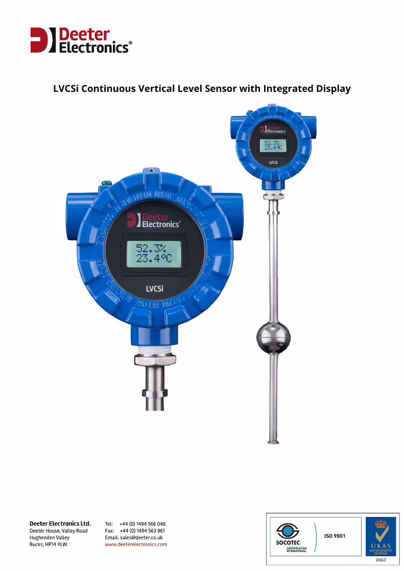
LVCSi Continuous Vertical Level Sensor with Integrated Display
LVCSi Continuous Vertical Level Sensor with Integrated Display
Table of Contents 1. Introduction .................................................................................................................. 3 2. Main Features ............................................................................................................... 4 2.1 Sensor Inputs ..................................................................................................................................................... 4 2.2 Display................................................................................................................................................................. 5 2.3 Analogue Outputs ............................................................................................................................................. 6 2.4 Digital Outputs .................................................................................................................................................. 7 2.5 Serial Communications ................................................................................................................................... 7 3. Installation .................................................................................................................... 8 3.1 Mounting the Sensor Stem ............................................................................................................................. 8 3.2 External Wiring .................................................................................................................................................. 8 3.2.1 Power Supply ..................................................................................................................................................... 8 3.2.2 Analogue Outputs ............................................................................................................................................. 9 3.2.3 Digital Outputs .................................................................................................................................................. 9 3.2.4 RS485 Communications ................................................................................................................................ 10 3.3 Inverting the LVCSi ......................................................................................................................................... 10 4. Configuration Setup ................................................................................................... 11 4.1 Option Menus .................................................................................................................................................. 11 4.2 Level Display .................................................................................................................................................... 13 4.3 Temperature Display ..................................................................................................................................... 14 4.4 Display Brightness .......................................................................................................................................... 14 4.5 Analogue Output 1 ......................................................................................................................................... 15 4.6 Analogue Output 2 ......................................................................................................................................... 15 4.7 Analogue Output Calibration ....................................................................................................................... 17 4.8 Temperature Sensor Calibration ................................................................................................................. 19 4.9 Digital Output Setup ...................................................................................................................................... 19 4.10 Digital Output Test ......................................................................................................................................... 20 4.11 Communications Setup ................................................................................................................................. 20 5. Operating States ......................................................................................................... 21 5.1 Start-up ............................................................................................................................................................. 21 5.2 Normal Operation .......................................................................................................................................... 21 5.3 Missing Level Sensor ...................................................................................................................................... 22 5.4 Missing Temperature Sensor ....................................................................................................................... 22 5.5 Current-Loop Fault ......................................................................................................................................... 22 5.6 Supply Voltage ................................................................................................................................................. 22 6. RS485 Serial Communications ................................................................................... 23 6.1 Deeter ASCII Protocol ..................................................................................................................................... 24 6.2 Modbus RTU .................................................................................................................................................... 28 6.2.1 Supported Function Codes ................................................................................................................... 28 6.2.2 Register Assignments ............................................................................................................................ 28 6.2.3 Bit Assignments ...................................................................................................................................... 29 6.2.4 Broadcast and Exception Responses ................................................................................................... 31 6.3 Modbus ASCII .................................................................................................................................................. 32 7. Specifications .............................................................................................................. 33

LVCSi Continuous Vertical Level Sensor with Integrated Display
Introduction The LVCSi is an analogue vertical level sensor with an integrated display meter and output driver specifically designed for continuous, in-situ monitoring of your tank. It is an extension of Deeter Electronics’ range of LVCS analogue level sensors and includes a temperature sensing option. The LVCSi features:
A display for direct read-out of level and temperature Two pairs of analogue outputs (4-20mA and 0-10V) Two set point digital outputs An RS485 communications port IP Rating of IP68 Stem Lengths up to 2000mm Optional Temperature Sensor Optional Modbus
Setup menus enable the selection of a wide range of options to suit the installation, with options saved to non-volatile memory. The level display range is user-programmable with a choice of length and volume units. Temperatures are shown in degrees Celsius, degrees Fahrenheit or Kelvin to one decimal place. The two analogue outputs each have 4-20mA current-loop and voltage output terminals. The voltage outputs have user-selectable ranges of 0-10V, 0-5V and 0-2V. Analogue Output 1 is reserved as a level output and Analogue Output 2 can be assigned to level or temperature. The two digital transistor outputs have programmable ON and OFF set-points and each can be assigned to activate at level or temperature thresholds. The LVCSi has an RS485 communications port with a selection of four baud rates and three communications protocols: Modbus RTU, Modbus ASCII and ‘Deeter ASCII’. The Deeter ASCII protocol comes as standard and enables remote monitoring of level, temperature and instrument status. The Modbus protocols are an optional extra and provide for full remote monitoring and control, including selection of setup options.
LVCSi Continuous Vertical Level Sensor with Integrated Display
2. Main Features 2.1 Sensor Inputs
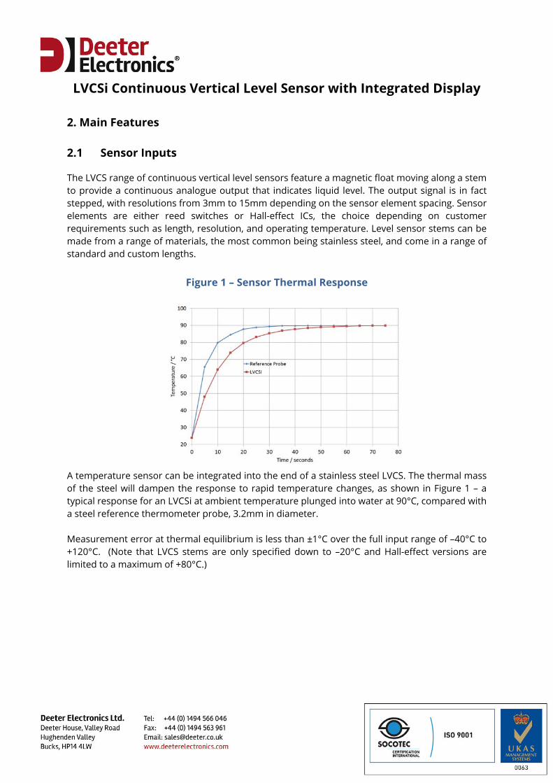
The LVCS range of continuous vertical level sensors feature a magnetic float moving along a stem to provide a continuous analogue output that indicates liquid level. The output signal is in fact stepped, with resolutions from 3mm to 15mm depending on the sensor element spacing. Sensor elements are either reed switches or Hall-effect ICs, the choice depending on customer requirements such as length, resolution, and operating temperature. Level sensor stems can be made from a range of materials, the most common being stainless steel, and come in a range of standard and custom lengths.
Figure 1 – Sensor Thermal Response A temperature sensor can be integrated into the end of a stainless steel LVCS. The thermal mass of the steel will dampen the response to rapid temperature changes, as shown in Figure 1 – a typical response for an LVCSi at ambient temperature plunged into water at 90°C, compared with a steel reference thermometer probe, 3.2mm in diameter. Measurement error at thermal equilibrium is less than ±1°C over the full input range of –40°C to +120°C. (Note that LVCS stems are only specified down to –20°C and Hall-effect versions are limited to a maximum of +80°C.)
LVCSi Continuous Vertical Level Sensor with Integrated Display
2.2 Display
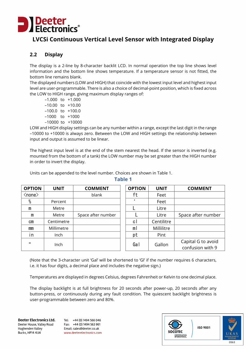
The display is a 2-line by 8-character backlit LCD. In normal operation the top line shows level information and the bottom line shows temperature. If a temperature sensor is not fitted, the bottom line remains blank. The displayed numbers (LOW and HIGH) that coincide with the lowest input level and highest input level are user-programmable. There is also a choice of decimal-point position, which is fixed across the LOW to HIGH range, giving maximum display ranges of: –1.000 to +1.000 –10.00 to +10.00 –100.0 to +100.0 –1000 to +1000 –10000 to +10000 LOW and HIGH display settings can be any number within a range, except the last digit in the range –10000 to +10000 is always zero. Between the LOW and HIGH settings the relationship between input and output is assumed to be linear. The highest input level is at the end of the stem nearest the head. If the sensor is inverted (e.g. mounted from the bottom of a tank) the LOW number may be set greater than the HIGH number in order to invert the display. Units can be appended to the level number. Choices are shown in Table 1.
Table 1
OPTION UNIT COMMENT OPTION UNIT COMMENT <none> blank ft Feet % Percent ‘ Feet m Metre L Litre m Metre Space after number L Litre Space after number cm Centimetre cl Centilitre mm Millimetre ml Millilitre in Inch pt Pint
“ Inch Gal Gallon Capital G to avoid confusion with 9
(Note that the 3-character unit ‘Gal’ will be shortened to ‘Gl’ if the number requires 6 characters, i.e. it has four digits, a decimal place and includes the negative sign.) Temperatures are displayed in degrees Celsius, degrees Fahrenheit or Kelvin to one decimal place. The display backlight is at full brightness for 20 seconds after power-up, 20 seconds after any button-press, or continuously during any fault condition. The quiescent backlight brightness is user-programmable between zero and 80%.
LVCSi Continuous Vertical Level Sensor with Integrated Display
2.3 Analogue Outputs
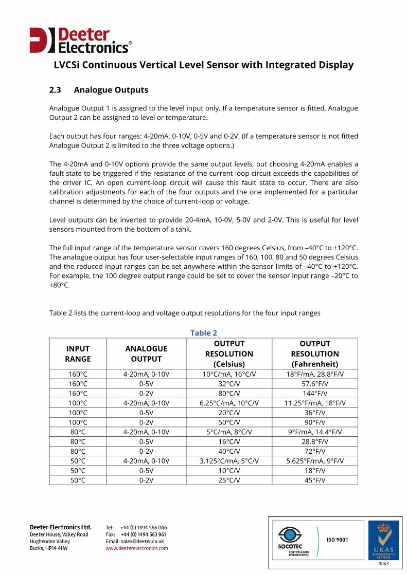
Analogue Output 1 is assigned to the level input only. If a temperature sensor is fitted, Analogue Output 2 can be assigned to level or temperature. Each output has four ranges: 4-20mA, 0-10V, 0-5V and 0-2V. (If a temperature sensor is not fitted Analogue Output 2 is limited to the three voltage options.) The 4-20mA and 0-10V options provide the same output levels, but choosing 4-20mA enables a fault state to be triggered if the resistance of the current loop circuit exceeds the capabilities of the driver IC. An open current-loop circuit will cause this fault state to occur. There are also calibration adjustments for each of the four outputs and the one implemented for a particular channel is determined by the choice of current-loop or voltage. Level outputs can be inverted to provide 20-4mA, 10-0V, 5-0V and 2-0V. This is useful for level sensors mounted from the bottom of a tank. The full input range of the temperature sensor covers 160 degrees Celsius, from –40°C to +120°C. The analogue output has four user-selectable input ranges of 160, 100, 80 and 50 degrees Celsius and the reduced input ranges can be set anywhere within the sensor limits of –40°C to +120°C. For example, the 100 degree output range could be set to cover the sensor input range –20°C to +80°C. Table 2 lists the current-loop and voltage output resolutions for the four input ranges
Table 2
INPUT RANGE
ANALOGUE OUTPUT
OUTPUT RESOLUTION
(Celsius)
OUTPUT RESOLUTION (Fahrenheit)
160°C 4-20mA, 0-10V 10°C/mA, 16°C/V 18°F/mA, 28.8°F/V 160°C 0-5V 32°C/V 57.6°F/V 160°C 0-2V 80°C/V 144°F/V 100°C 4-20mA, 0-10V 6.25°C/mA, 10°C/V 11.25°F/mA, 18°F/V 100°C 0-5V 20°C/V 36°F/V 100°C 0-2V 50°C/V 90°F/V 80°C 4-20mA, 0-10V 5°C/mA, 8°C/V 9°F/mA, 14.4°F/V 80°C 0-5V 16°C/V 28.8°F/V 80°C 0-2V 40°C/V 72°F/V 50°C 4-20mA, 0-10V 3.125°C/mA, 5°C/V 5.625°F/mA, 9°F/V 50°C 0-5V 10°C/V 18°F/V 50°C 0-2V 25°C/V 45°F/V
LVCSi Continuous Vertical Level Sensor with Integrated Display
2.4 Digital Outputs
There are two open-collector NPN transistor outputs. When inactive (OFF) they require an external pull-up (maximum of 36V) and when active (ON) they connect to the 0V rail and can sink up to 50mA. Each transistor has user-selectable ON and OFF thresholds that can be assigned to level or temperature inputs. When assigned to level, thresholds are represented as a percentage between 0% (float at bottom of stem) and 100% (float at top of stem). When assigned to temperature, thresholds are in degrees Celsius or Fahrenheit. If the ON threshold is greater than the OFF threshold, the transistor will be active when the input is high and inactive when the input is low. If ON is less than OFF, the transistor will be active when the input is low and inactive when the input is high. Between ON and OFF thresholds the active/inactive state depends on the last threshold the input has passed. Setting ON equal to OFF is not recommended because some hysteresis is usually required to prevent the output ‘chattering’ when the input hovers around the threshold. If settings are made equal, the transistor will be active when the input is above the threshold and inactive below the threshold. 2.5 Serial Communications
Serial communications are asynchronous using half-duplex RS485 signals with a fixed data format of 8 data bits, no parity and 1 stop bit. There are four user-selectable baud rates: 2400, 9600, 19200 and 38400. The LVCSi is a slave device, responding to commands initiated by a bus master. A simplified ASCII protocol, ‘Deeter ASCII’, comes as standard. This uses ASCII characters in the displayable range 20h to 7Eh, making commands easy to generate and responses easy to view and interpret on a PC with readily available terminal-emulation software. Commands are limited to monitoring of inputs and status information. The optional Modbus protocols allow for full remote monitoring and setup. The LVCSi conforms to the Modbus RTU and Modbus ASCII command and response framing standards as a slave device – see section 6 for details.
LVCSi Continuous Vertical Level Sensor with Integrated Display
3. Installation
3.1 Mounting the Sensor Stem
To mount the LVCSi in a tank, first separate the two assemblies: unscrew and remove the glass cover of the head assembly pull off the LCD surround remove the two screws securing the circuit assembly to the support pillars slide the PCB assembly forward over the two support pillars disconnect the cables from the sensor stem at connectors J1 and J2
Unscrew the stem from the head and mount the stem inside the tank. LVCS stems have a variety of mounting options to suit customer requirements. Refit the temperature sensor connector to the 2-way header, J1. Refit the level sensor connector to J2. J2 can be a 2-way, 3-way or 5-way header depending on the type of level sensor. 5-way headers are split into a 2-way plus 3-way. The head is secured to the stem by screwing the two back together. 3.2 External Wiring
All external connections go to the two rows of screw terminals on the underside of the bottom PCB. Cables must be fed through the ports at the back of the enclosure with enough slack to reach the screw terminals while the circuit is pulled forward to gain access to these terminals. The following sections describe connections to the screw terminals. After connections have been made, reassemble the circuit by reversing the actions and reversing the order of the disassembly listing in section 3.1. 3.2.1 Power Supply
The LVCSi is supplied with a 24VDC mains adapter power supply. The red sleeved wire is positive and goes to the ‘POWER Vin’ terminal. The un-sleeved wire goes to the ‘POWER 0V’ terminal. Power requirements are 15-30V at 100mA.
LVCSi Continuous Vertical Level Sensor with Integrated Display
3.2.2 Analogue Outputs
There are two independently driven analogue outputs, each having terminals for voltage and current, making four analogue outputs in total. These are arranged as a single block of 8 screw terminals on the underside of the bottom PCB. (If a temperature sensor is not fitted, this is a 6-way connector with no provision for the Analogue Output 2 current-loop). Analogue Output 1 is always assigned to level. Output 2 can be assigned to level or temperature. Connections can be made to both sets of terminals from a single analogue output and the voltages and currents will correlate. However, if 5V or 2V output ranges are selected the current will be limited to ranges of 4-12mA or 4-7.2mA. Also, the calibration adjustments used for a channel are based on the choice of current or voltage output (see section 4.7), so the other output will be slightly out of adjustment. 3.2.3 Digital Outputs
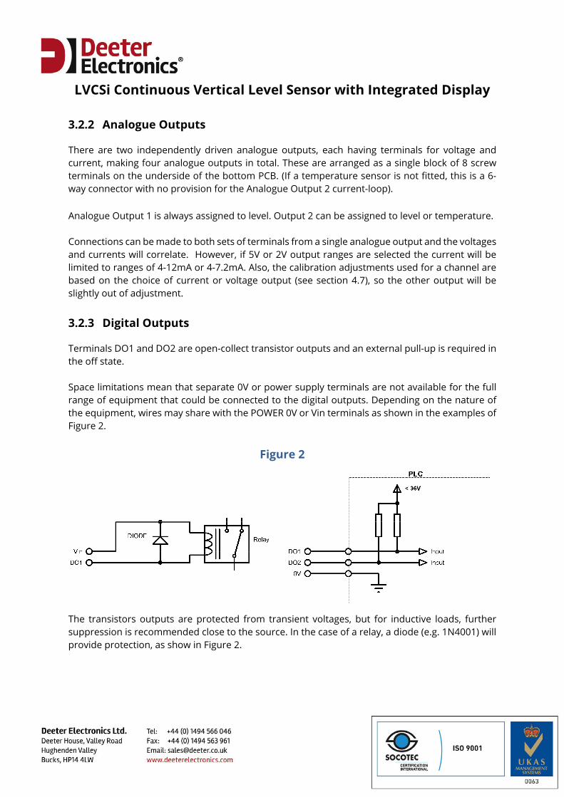
Terminals DO1 and DO2 are open-collect transistor outputs and an external pull-up is required in the off state. Space limitations mean that separate 0V or power supply terminals are not available for the full range of equipment that could be connected to the digital outputs. Depending on the nature of the equipment, wires may share with the POWER 0V or Vin terminals as shown in the examples of Figure 2.
Figure 2
The transistors outputs are protected from transient voltages, but for inductive loads, further suppression is recommended close to the source. In the case of a relay, a diode (e.g. 1N4001) will provide protection, as show in Figure 2.
LVCSi Continuous Vertical Level Sensor with Integrated Display
3.2.4 RS485 Communications
The RS485 serial communications port is half-duplex, using the balanced-pair lines D+ and D–. Connections to the bus master are:
LVCSi MASTER D+ D+ or A D– D– or B 0V 0V or SC or G
A line-termination resistor can be enabled by moving LK1 to the TERM position. For a multi-drop configuration only the end device should have this link in the TERM position. 3.3 Inverting the LVCSi
The LVCSi can be mounted to the top or bottom of a tank. Default settings are for top-mounting, with low analogue and display levels associated with the float at the end of the stem away from the head. If mounting the LVCSi the other way up (e.g. below a tank):
Mount the display the other way up inside its housing Reverse display settings by making the ‘LOW’ level greater than the ‘HIGH’ level (see section
4.2) Select ‘INVERT’ for analogue outputs (see section 4.5) Convert digital output threshold percentages by subtracting from 100%
LVCSi Continuous Vertical Level Sensor with Integrated Display
4. Configuration Setup
Three push buttons are used to navigate the configuration menus. These buttons are located below the display and are only accessible with the housing cover unscrewed, so configuration setup needs to be performed during installation. If Modbus communications options are used, most setup parameters (excluding communications settings) can be changed remotely at any time. Below each button is a symbol to indicate its function:
SYMBOL FUNCTION
UP
DOWN
ENTER In the following sections the buttons are referred to as UP, DOWN and ENTER. Option menus are organised into levels, with all top-level menus indicated by the enter symbol � in the bottom right corner or the display. The symbols ^ and v to the right of the display indicate that holding UP or DOWN buttons will rapidly increment or decrement the parameter on the screen. 4.1 Option Menus
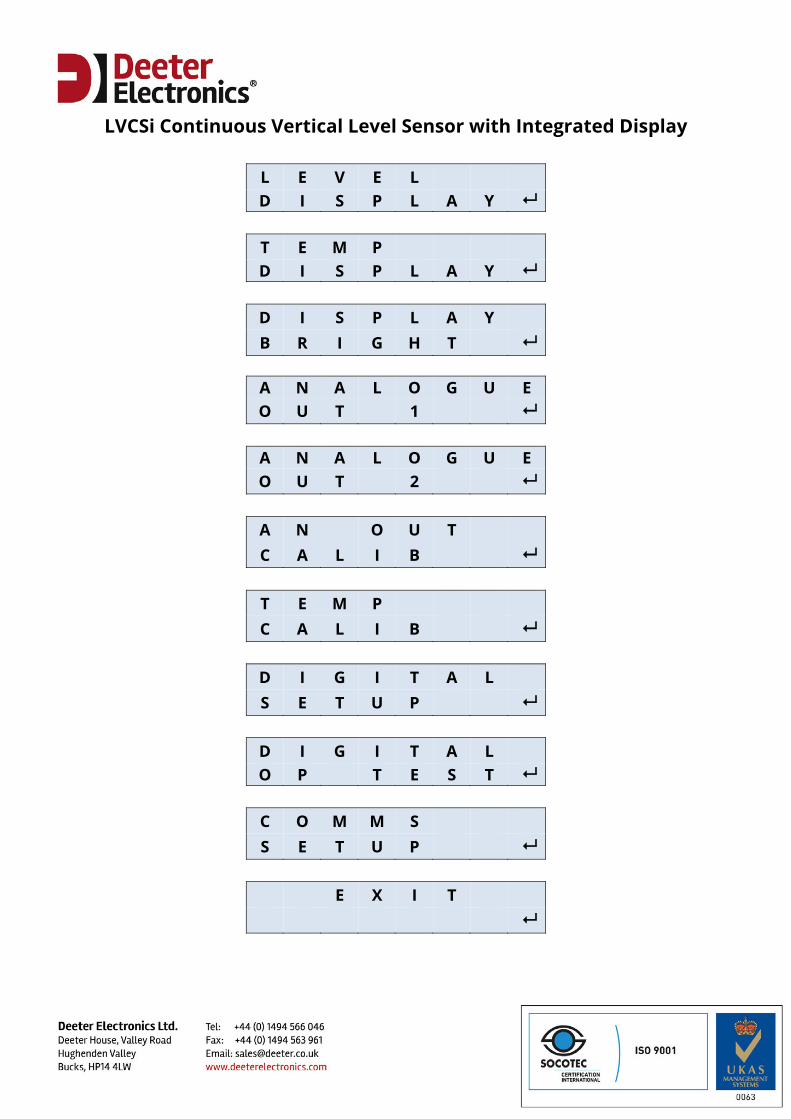
Option menus are accessed from normal operation (or fault states) by pressing and holding the ENTER button for 3 seconds. Pressing UP or DOWN will cycle through the top-level menus and ENTER will select a sub-menu. ENTER pressed from the EXIT menu will return to normal operation. Temperature Display and Temperature Calibration menus are not shown if a temperature sensor is not fitted.
LVCSi Continuous Vertical Level Sensor with Integrated Display
L E V E L D I S P L A Y
T E M P D I S P L A Y
D I S P L A Y B R I G H T
A N A L O G U E O U T 1
A N A L O G U E O U T 2
A N O U T C A L I B
T E M P C A L I B
D I G I T A L S E T U P
D I G I T A L O P T E S T
C O M M S S E T U P
E X I T
LVCSi Continuous Vertical Level Sensor with Integrated Display
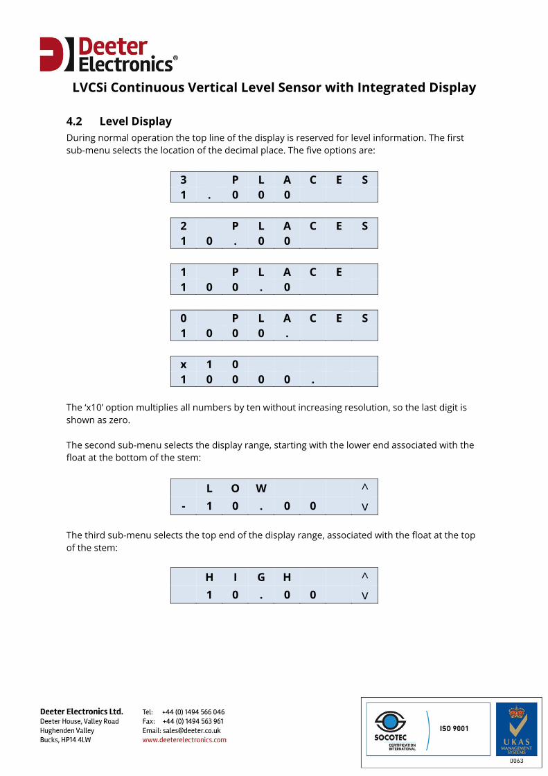
4.2 Level Display During normal operation the top line of the display is reserved for level information. The first sub-menu selects the location of the decimal place. The five options are:
3 P L A C E S 1 . 0 0 0
2 P L A C E S 1 0 . 0 0
1 P L A C E 1 0 0 . 0
0 P L A C E S 1 0 0 0 .
x 1 0 1 0 0 0 0 .
The ‘x10’ option multiplies all numbers by ten without increasing resolution, so the last digit is shown as zero. The second sub-menu selects the display range, starting with the lower end associated with the float at the bottom of the stem:
L O W ^ - 1 0 . 0 0 v
The third sub-menu selects the top end of the display range, associated with the float at the top of the stem:
H I G H ^ 1 0 . 0 0 v
LVCSi Continuous Vertical Level Sensor with Integrated Display
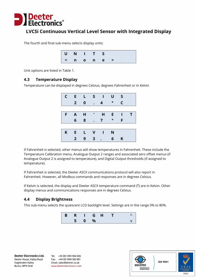
The fourth and final sub-menu selects display units:
U N I T S < n o n e >
Unit options are listed in Table 1.
4.3 Temperature Display Temperature can be displayed in degrees Celsius, degrees Fahrenheit or in Kelvin
C E L S I U S 2 0 . 4 ° C
F A H ‘ H E I T 6 8 . 7 ° F
K E L V I N 2 9 3 . 6 K
If Fahrenheit is selected, other menus will show temperatures in Fahrenheit. These include the Temperature Calibration menu, Analogue Output 2 ranges and associated zero offset menus (if Analogue Output 2 is assigned to temperature), and Digital Output thresholds (if assigned to temperature). If Fahrenheit is selected, the Deeter ASCII communications protocol will also report in Fahrenheit. However, all Modbus commands and responses are in degrees Celsius. If Kelvin is selected, the display and Deeter ASCII temperature command (T) are in Kelvin. Other display menus and communications responses are in degrees Celsius.
4.4 Display Brightness This sub-menu selects the quiescent LCD backlight level. Settings are in the range 0% to 80%.
B R I G H T ^ 5 0 % v
LVCSi Continuous Vertical Level Sensor with Integrated Display
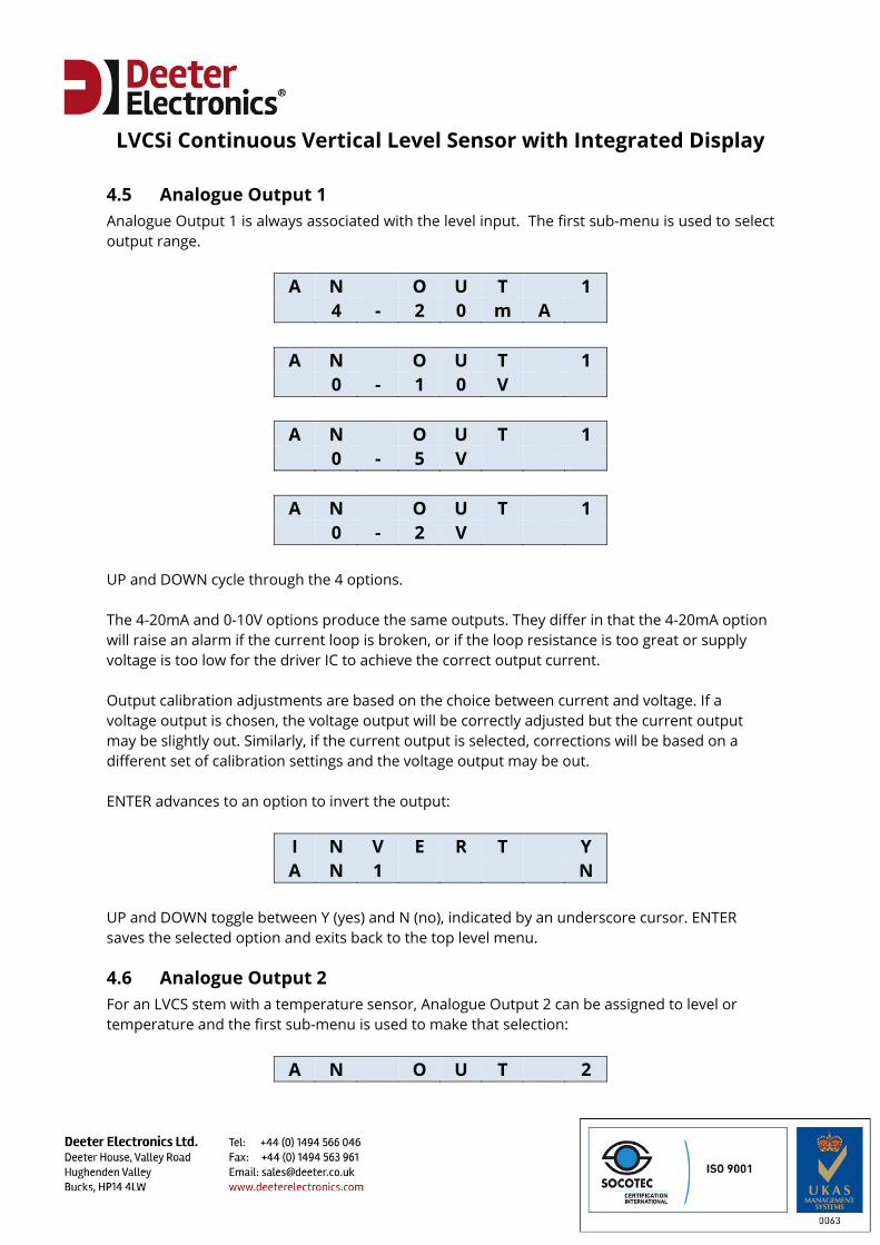
4.5 Analogue Output 1 Analogue Output 1 is always associated with the level input. The first sub-menu is used to select output range.
A N O U T 1 4 - 2 0 m A
A N O U T 1 0 - 1 0 V
A N O U T 1 0 - 5 V
A N O U T 1 0 - 2 V
UP and DOWN cycle through the 4 options. The 4-20mA and 0-10V options produce the same outputs. They differ in that the 4-20mA option will raise an alarm if the current loop is broken, or if the loop resistance is too great or supply voltage is too low for the driver IC to achieve the correct output current. Output calibration adjustments are based on the choice between current and voltage. If a voltage output is chosen, the voltage output will be correctly adjusted but the current output may be slightly out. Similarly, if the current output is selected, corrections will be based on a different set of calibration settings and the voltage output may be out. ENTER advances to an option to invert the output:
I N V E R T Y A N 1 N
UP and DOWN toggle between Y (yes) and N (no), indicated by an underscore cursor. ENTER saves the selected option and exits back to the top level menu.
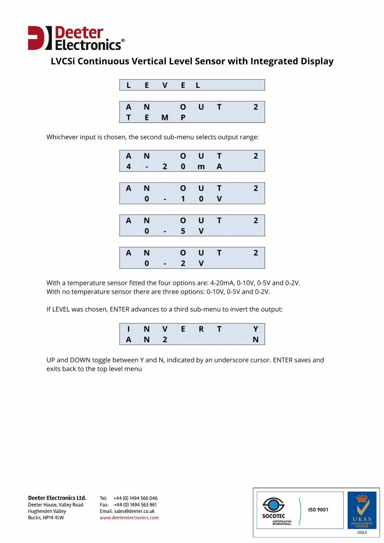
4.6 Analogue Output 2 For an LVCS stem with a temperature sensor, Analogue Output 2 can be assigned to level or temperature and the first sub-menu is used to make that selection:
A N O U T 2
LVCSi Continuous Vertical Level Sensor with Integrated Display
L E V E L
A N O U T 2 T E M P
Whichever input is chosen, the second sub-menu selects output range:
A N O U T 2 4 - 2 0 m A
A N O U T 2 0 - 1 0 V
A N O U T 2 0 - 5 V
A N O U T 2 0 - 2 V
With a temperature sensor fitted the four options are: 4-20mA, 0-10V, 0-5V and 0-2V. With no temperature sensor there are three options: 0-10V, 0-5V and 0-2V. If LEVEL was chosen, ENTER advances to a third sub-menu to invert the output:
I N V E R T Y A N 2 N
UP and DOWN toggle between Y and N, indicated by an underscore cursor. ENTER saves and exits back to the top level menu
LVCSi Continuous Vertical Level Sensor with Integrated Display
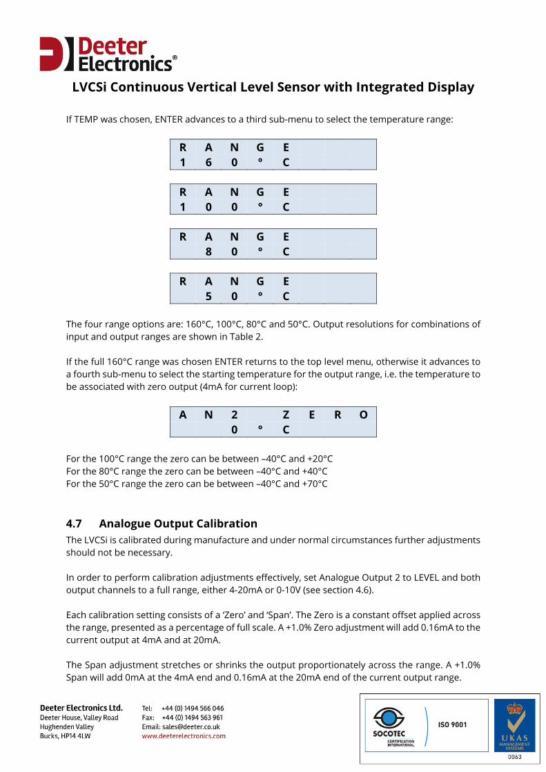
If TEMP was chosen, ENTER advances to a third sub-menu to select the temperature range:
R A N G E 1 6 0 ° C
R A N G E 1 0 0 ° C
R A N G E 8 0 ° C
R A N G E 5 0 ° C
The four range options are: 160°C, 100°C, 80°C and 50°C. Output resolutions for combinations of input and output ranges are shown in Table 2. If the full 160°C range was chosen ENTER returns to the top level menu, otherwise it advances to a fourth sub-menu to select the starting temperature for the output range, i.e. the temperature to be associated with zero output (4mA for current loop):
A N 2 Z E R O 0 ° C
For the 100°C range the zero can be between –40°C and +20°C For the 80°C range the zero can be between –40°C and +40°C For the 50°C range the zero can be between –40°C and +70°C
4.7 Analogue Output Calibration The LVCSi is calibrated during manufacture and under normal circumstances further adjustments should not be necessary. In order to perform calibration adjustments effectively, set Analogue Output 2 to LEVEL and both output channels to a full range, either 4-20mA or 0-10V (see section 4.6). Each calibration setting consists of a ‘Zero’ and ‘Span’. The Zero is a constant offset applied across the range, presented as a percentage of full scale. A +1.0% Zero adjustment will add 0.16mA to the current output at 4mA and at 20mA. The Span adjustment stretches or shrinks the output proportionately across the range. A +1.0% Span will add 0mA at the 4mA end and 0.16mA at the 20mA end of the current output range.
LVCSi Continuous Vertical Level Sensor with Integrated Display
C 1 Z 0 . 2 % 1 . 9 %
C 1 S 0 . 1 % 9 8 . 0 %
V 2 Z - 0 . 5 % 2 . 0 %
V 2 S 1 . 0 % 9 7 . 5 %
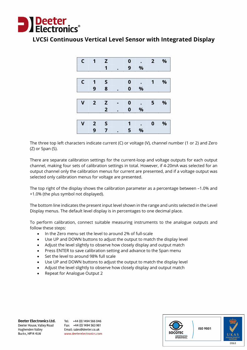
The three top left characters indicate current (C) or voltage (V), channel number (1 or 2) and Zero (Z) or Span (S). There are separate calibration settings for the current-loop and voltage outputs for each output channel, making four sets of calibration settings in total. However, if 4-20mA was selected for an output channel only the calibration menus for current are presented, and if a voltage output was selected only calibration menus for voltage are presented. The top right of the display shows the calibration parameter as a percentage between –1.0% and +1.0% (the plus symbol not displayed). The bottom line indicates the present input level shown in the range and units selected in the Level Display menus. The default level display is in percentages to one decimal place. To perform calibration, connect suitable measuring instruments to the analogue outputs and follow these steps:
In the Zero menu set the level to around 2% of full-scale Use UP and DOWN buttons to adjust the output to match the display level Adjust the level slightly to observe how closely display and output match Press ENTER to save calibration setting and advance to the Span menu Set the level to around 98% full scale Use UP and DOWN buttons to adjust the output to match the display level Adjust the level slightly to observe how closely display and output match Repeat for Analogue Output 2
LVCSi Continuous Vertical Level Sensor with Integrated Display
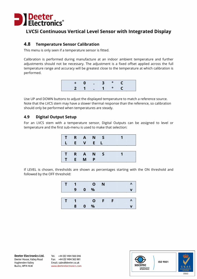
4.8 Temperature Sensor Calibration This menu is only seen if a temperature sensor is fitted. Calibration is performed during manufacture at an indoor ambient temperature and further adjustments should not be necessary. The adjustment is a fixed offset applied across the full temperature range and accuracy will be greatest close to the temperature at which calibration is performed.
+ 0 . 3 ° C 2 1 . 1 ° C
Use UP and DOWN buttons to adjust the displayed temperature to match a reference source. Note that the LVCS stem may have a slower thermal response than the reference, so calibration should only be performed when temperatures are steady.
4.9 Digital Output Setup For an LVCS stem with a temperature sensor, Digital Outputs can be assigned to level or temperature and the first sub-menu is used to make that selection:
T R A N S 1 L E V E L
T R A N S 1 T E M P
If LEVEL is chosen, thresholds are shown as percentages starting with the ON threshold and followed by the OFF threshold:
T 1 O N ^ 9 0 % v
T 1 O F F ^ 8 0 % v
LVCSi Continuous Vertical Level Sensor with Integrated Display
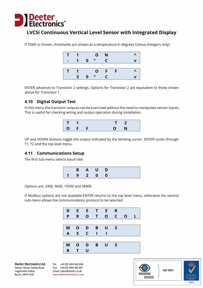
If TEMP is chosen, thresholds are shown as a temperature in degrees Celsius (integers only)
T 1 O N ^ - 1 0 ° C v
T 1 O F F ^ 3 0 ° C v
ENTER advances to Transistor 2 settings. Options for Transistor 2 are equivalent to those shown above for Transistor 1.
4.10 Digital Output Test In this menu the transistor outputs can be exercised without the need to manipulate sensor inputs. This is useful for checking wiring and output operation during installation.
T 1 T 2 O F F O N
UP and DOWN buttons toggle the output indicated by the blinking cursor. ENTER cycles through T1, T2 and the top level menu.
4.11 Communications Setup The first sub-menu selects baud rate:
B A U D 1 9 2 0 0
Options are: 2400, 9600, 19200 and 38400 If Modbus options are not available ENTER returns to the top level menu, otherwise the second sub-menu allows the communications protocol to be selected:
D E E T E R P R O T O C O L
M O D B U S A S C I I
M O D B U S R T U
LVCSi Continuous Vertical Level Sensor with Integrated Display
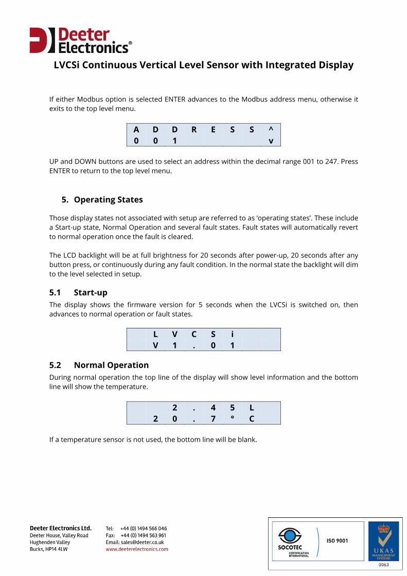
If either Modbus option is selected ENTER advances to the Modbus address menu, otherwise it exits to the top level menu.
A D D R E S S ^ 0 0 1 v
UP and DOWN buttons are used to select an address within the decimal range 001 to 247. Press ENTER to return to the top level menu.
5. Operating States
Those display states not associated with setup are referred to as ‘operating states’. These include a Start-up state, Normal Operation and several fault states. Fault states will automatically revert to normal operation once the fault is cleared. The LCD backlight will be at full brightness for 20 seconds after power-up, 20 seconds after any button press, or continuously during any fault condition. In the normal state the backlight will dim to the level selected in setup.
5.1 Start-up The display shows the firmware version for 5 seconds when the LVCSi is switched on, then advances to normal operation or fault states.
L V C S i V 1 . 0 1
5.2 Normal Operation During normal operation the top line of the display will show level information and the bottom line will show the temperature.
2 . 4 5 L 2 0 . 7 ° C
If a temperature sensor is not used, the bottom line will be blank.
LVCSi Continuous Vertical Level Sensor with Integrated Display
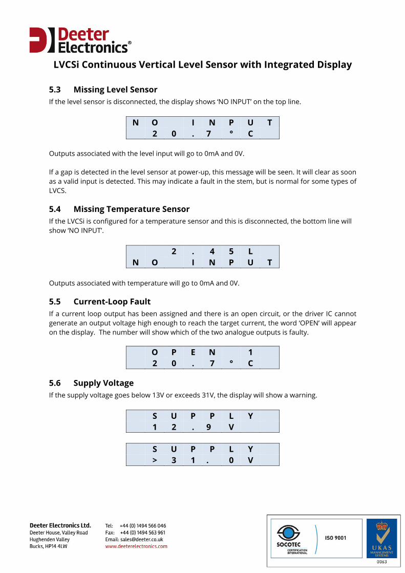
5.3 Missing Level Sensor If the level sensor is disconnected, the display shows ‘NO INPUT’ on the top line.
N O I N P U T 2 0 . 7 ° C
Outputs associated with the level input will go to 0mA and 0V. If a gap is detected in the level sensor at power-up, this message will be seen. It will clear as soon as a valid input is detected. This may indicate a fault in the stem, but is normal for some types of LVCS.
5.4 Missing Temperature Sensor If the LVCSi is configured for a temperature sensor and this is disconnected, the bottom line will show ‘NO INPUT’.
2 . 4 5 L N O I N P U T
Outputs associated with temperature will go to 0mA and 0V.
5.5 Current-Loop Fault If a current loop output has been assigned and there is an open circuit, or the driver IC cannot generate an output voltage high enough to reach the target current, the word ‘OPEN’ will appear on the display. The number will show which of the two analogue outputs is faulty.
O P E N 1 2 0 . 7 ° C
5.6 Supply Voltage If the supply voltage goes below 13V or exceeds 31V, the display will show a warning.
S U P P L Y 1 2 . 9 V
S U P P L Y > 3 1 . 0 V
LVCSi Continuous Vertical Level Sensor with Integrated Display
6. RS485 Serial Communications
The LVCSi is a slave device responding to commands initiated by an RS485 bus master. The data format is fixed as:
8 data bits, no parity, 1 stop bit. There are four user-selectable baud rates: 2400, 9600, 19200, 38400. Three communication protocols are supported:
Deeter ASCI Modbus RTU Modbus ASCII
LVCSi Continuous Vertical Level Sensor with Integrated Display
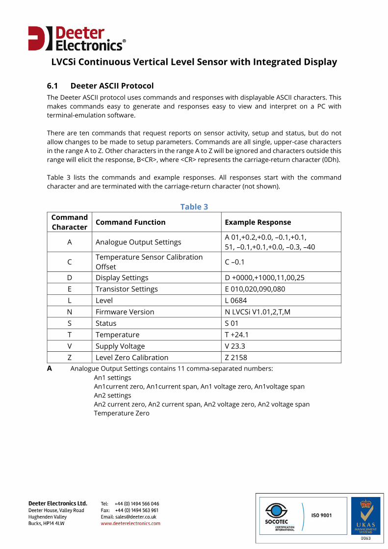
6.1 Deeter ASCII Protocol The Deeter ASCII protocol uses commands and responses with displayable ASCII characters. This makes commands easy to generate and responses easy to view and interpret on a PC with terminal-emulation software. There are ten commands that request reports on sensor activity, setup and status, but do not allow changes to be made to setup parameters. Commands are all single, upper-case characters in the range A to Z. Other characters in the range A to Z will be ignored and characters outside this range will elicit the response, B<CR>, where <CR> represents the carriage-return character (0Dh). Table 3 lists the commands and example responses. All responses start with the command character and are terminated with the carriage-return character (not shown).
Table 3
Command Character
Command Function Example Response
A Analogue Output Settings A 01,+0.2,+0.0, –0.1,+0.1, 51, –0.1,+0.1,+0.0, –0.3, –40
C Temperature Sensor Calibration Offset
C –0.1
D Display Settings D +0000,+1000,11,00,25 E Transistor Settings E 010,020,090,080 L Level L 0684 N Firmware Version N LVCSi V1.01,2,T,M S Status S 01 T Temperature T +24.1 V Supply Voltage V 23.3 Z Level Zero Calibration Z 2158
A Analogue Output Settings contains 11 comma-separated numbers: An1 settings
An1current zero, An1current span, An1 voltage zero, An1voltage span An2 settings An2 current zero, An2 current span, An2 voltage zero, An2 voltage span Temperature Zero
LVCSi Continuous Vertical Level Sensor with Integrated Display
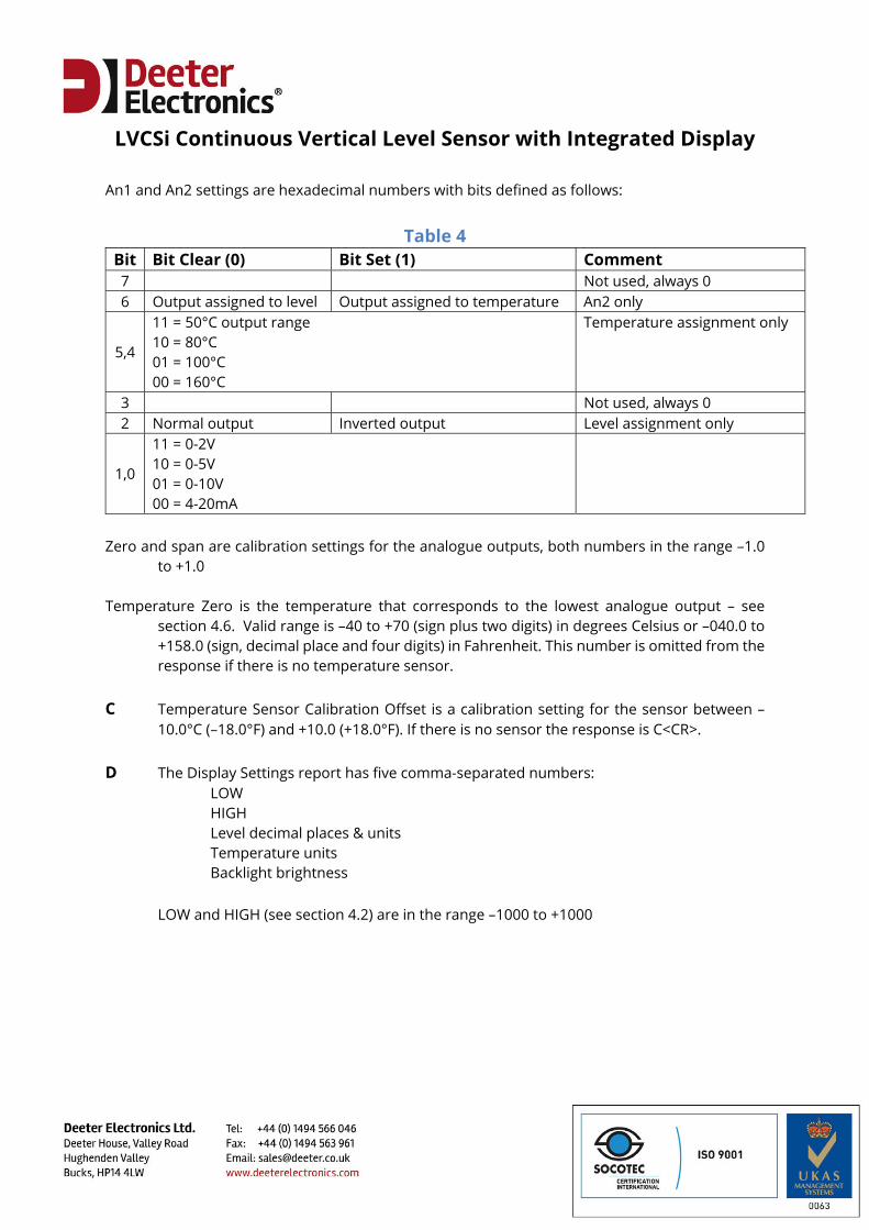
An1 and An2 settings are hexadecimal numbers with bits defined as follows:
Table 4 Bit Bit Clear (0) Bit Set (1) Comment 7 Not used, always 0 6 Output assigned to level Output assigned to temperature An2 only
5,4
11 = 50°C output range 10 = 80°C 01 = 100°C 00 = 160°C
Temperature assignment only
3 Not used, always 0 2 Normal output Inverted output Level assignment only
1,0
11 = 0-2V 10 = 0-5V 01 = 0-10V 00 = 4-20mA
Zero and span are calibration settings for the analogue outputs, both numbers in the range –1.0
to +1.0 Temperature Zero is the temperature that corresponds to the lowest analogue output – see
section 4.6. Valid range is –40 to +70 (sign plus two digits) in degrees Celsius or –040.0 to +158.0 (sign, decimal place and four digits) in Fahrenheit. This number is omitted from the response if there is no temperature sensor.
C Temperature Sensor Calibration Offset is a calibration setting for the sensor between –
10.0°C (–18.0°F) and +10.0 (+18.0°F). If there is no sensor the response is C<CR>. D The Display Settings report has five comma-separated numbers: LOW HIGH Level decimal places & units Temperature units Backlight brightness
LOW and HIGH (see section 4.2) are in the range –1000 to +1000
LVCSi Continuous Vertical Level Sensor with Integrated Display
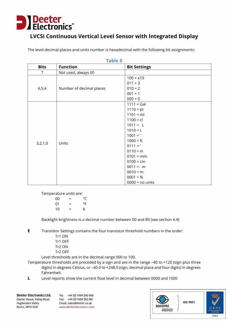
The level-decimal-places-and-units number is hexadecimal with the following bit assignments:
Table 5 Bits Function Bit Settings
7 Not used, always 00
6,5,4 Number of decimal places
100 = x10 011 = 3 010 = 2 001 = 1 000 = 0
3,2,1,0 Units
1111 = Gal 1110 = pt 1101 = ml 1100 = cl 1011 = L 1010 = L 1001 = ‘ 1000 = ft 0111 = ‘ 0110 = in 0101 = mm 0100 = cm 0011 = m 0010 = m 0001 = % 0000 = no units
Temperature units are: 00 = °C 01 = °F 10 = K Backlight brightness is a decimal number between 00 and 80 (see section 4.4)
E Transistor Settings contains the four transistor threshold numbers in the order:
Tr1 ON Tr1 OFF
Tr2 ON Tr2 OFF
Level thresholds are in the decimal range 000 to 100. Temperature thresholds are preceded by a sign and are in the range –40 to +120 (sign plus three
digits) in degrees Celsius, or –40.0 to +248.0 (sign, decimal place and four digits) in degrees Fahrenheit.
L Level reports show the current float level in decimal between 0000 and 1000
LVCSi Continuous Vertical Level Sensor with Integrated Display
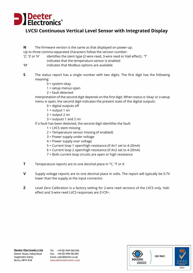
N The firmware version is the same as that displayed on power-up. Up to three comma-separated characters follow the version number: ‘2’, ‘3’ or ‘H’ identifies the stem type (2-wire reed, 3-wire reed or Hall-effect). ‘T’
indicates that the temperature sensor is enabled ‘M’ indicates that Modbus options are available S The status report has a single number with two digits. The first digit has the following
meaning: 0 = system okay 1 = setup menus open 2 = fault detected Interpretation of the second digit depends on the first digit. When status is ‘okay’ or a setup
menu is open, the second digit indicates the present state of the digital outputs: 0 = digital outputs off 1 = output 1 on 2 = output 2 on 3 = outputs 1 and 2 on If a fault has been detected, the second digit identifies the fault: 1 = LVCS stem missing 2 = Temperature sensor missing (if enabled) 3 = Power supply under voltage 4 = Power supply over voltage 5 = Current loop 1 open/high resistance (if An1 set to 4-20mA) 6 = Current loop 2 open/high resistance (if An2 set to 4-20mA) 7 = Both current loop circuits are open or high resistance T Temperature reports are to one decimal place in °C, °F or K V Supply voltage reports are to one decimal place in volts. The report will typically be 0.7V
lower than the supply at the input connector. Z Level Zero Calibration is a factory setting for 2-wire reed versions of the LVCS only. Hall-
effect and 3-wire reed LVCS responses are Z<CR>.
LVCSi Continuous Vertical Level Sensor with Integrated Display
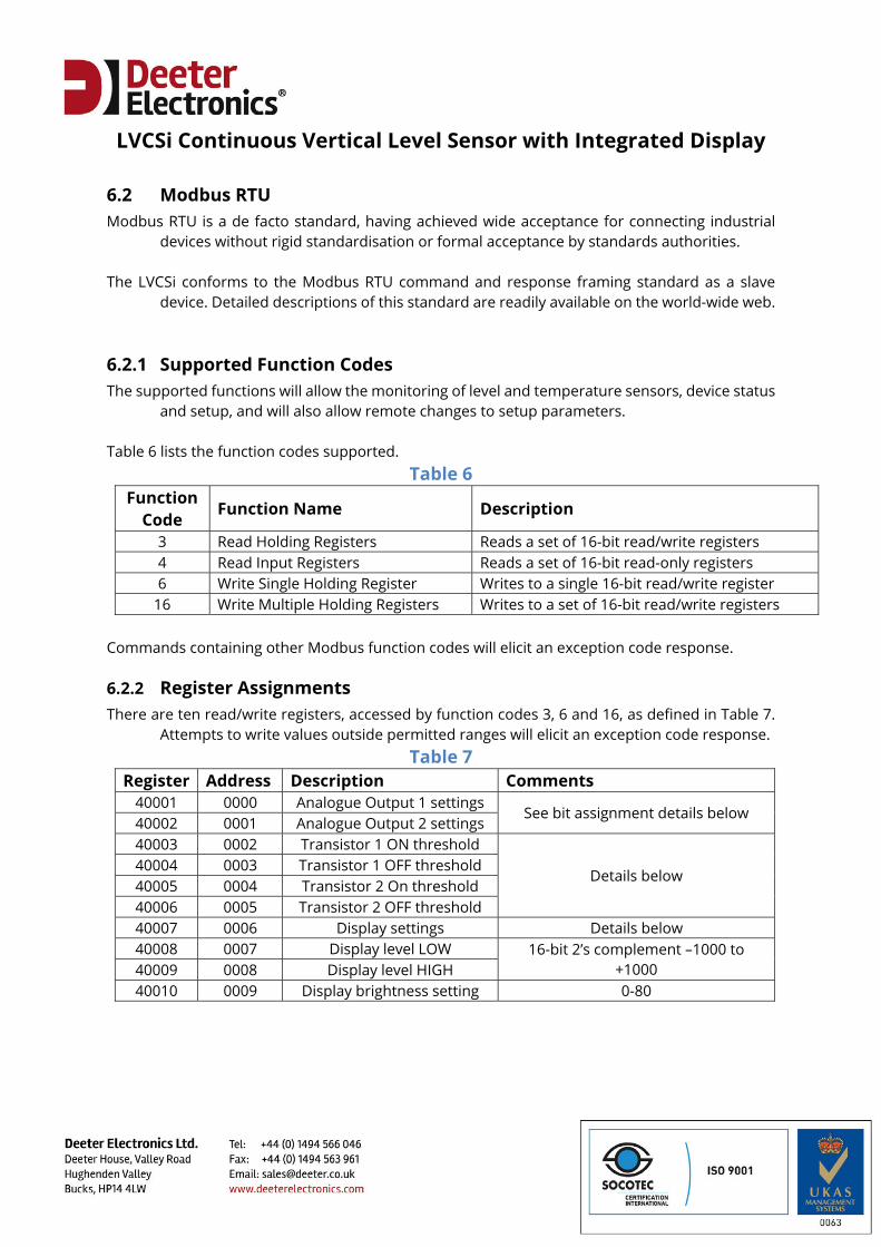
6.2 Modbus RTU Modbus RTU is a de facto standard, having achieved wide acceptance for connecting industrial
devices without rigid standardisation or formal acceptance by standards authorities. The LVCSi conforms to the Modbus RTU command and response framing standard as a slave
device. Detailed descriptions of this standard are readily available on the world-wide web.
6.2.1 Supported Function Codes The supported functions will allow the monitoring of level and temperature sensors, device status
and setup, and will also allow remote changes to setup parameters. Table 6 lists the function codes supported.
Table 6 Function
Code Function Name Description
3 Read Holding Registers Reads a set of 16-bit read/write registers 4 Read Input Registers Reads a set of 16-bit read-only registers 6 Write Single Holding Register Writes to a single 16-bit read/write register
16 Write Multiple Holding Registers Writes to a set of 16-bit read/write registers Commands containing other Modbus function codes will elicit an exception code response.
6.2.2 Register Assignments There are ten read/write registers, accessed by function codes 3, 6 and 16, as defined in Table 7.
Attempts to write values outside permitted ranges will elicit an exception code response. Table 7
Register Address Description Comments 40001 0000 Analogue Output 1 settings
See bit assignment details below 40002 0001 Analogue Output 2 settings 40003 0002 Transistor 1 ON threshold
Details below 40004 0003 Transistor 1 OFF threshold 40005 0004 Transistor 2 On threshold 40006 0005 Transistor 2 OFF threshold 40007 0006 Display settings Details below 40008 0007 Display level LOW 16-bit 2’s complement –1000 to
+1000 40009 0008 Display level HIGH 40010 0009 Display brightness setting 0-80
LVCSi Continuous Vertical Level Sensor with Integrated Display
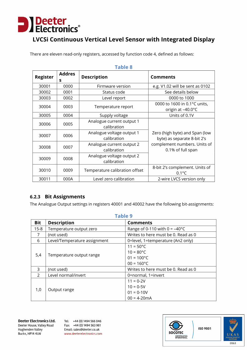
There are eleven read-only registers, accessed by function code 4, defined as follows:
Table 8
Register Address
Description Comments
30001 0000 Firmware version e.g. V1.02 will be sent as 0102 30002 0001 Status code See details below 30003 0002 Level report 0000 to 1000
30004 0003 Temperature report 0000 to 1600 in 0.1°C units,
origin at –40.0°C 30005 0004 Supply voltage Units of 0.1V
30006 0005 Analogue current output 1
calibration Zero (high byte) and Span (low
byte) as separate 8-bit 2’s complement numbers. Units of
0.1% of full span
30007 0006 Analogue voltage output 1
calibration
30008 0007 Analogue current output 2
calibration
30009 0008 Analogue voltage output 2
calibration
30010 0009 Temperature calibration offset 8-bit 2’s complement. Units of
0.1°C 30011 000A Level zero calibration 2-wire LVCS version only
6.2.3 Bit Assignments The Analogue Output settings in registers 40001 and 40002 have the following bit-assignments:
Table 9 Bit Description Comments 15-8 Temperature output zero Range of 0-110 with 0 = –40°C
7 (not used) Writes to here must be 0. Read as 0 6 Level/Temperature assignment 0=level, 1=temperature (An2 only)
5,4 Temperature output range
11 = 50°C 10 = 80°C 01 = 100°C 00 = 160°C
3 (not used) Writes to here must be 0. Read as 0 2 Level normal/invert 0=normal, 1=invert
1,0 Output range
11 = 0-2V 10 = 0-5V 01 = 0-10V 00 = 4-20mA
LVCSi Continuous Vertical Level Sensor with Integrated Display
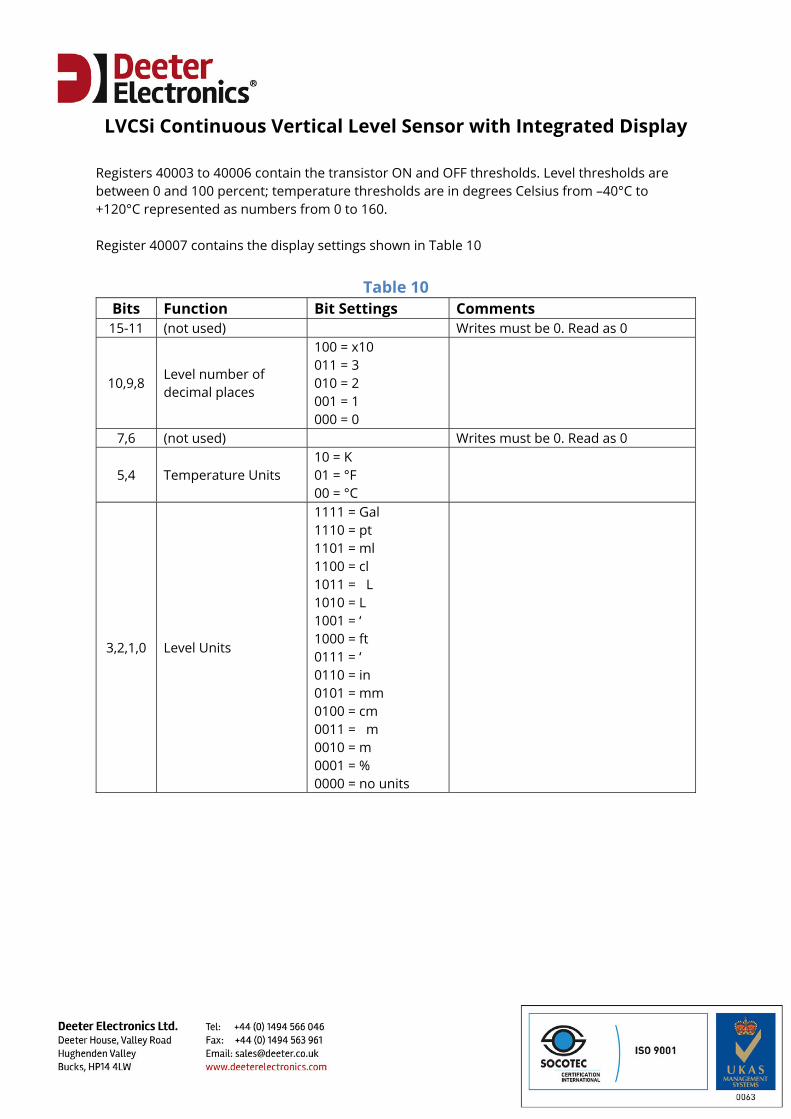
Registers 40003 to 40006 contain the transistor ON and OFF thresholds. Level thresholds are between 0 and 100 percent; temperature thresholds are in degrees Celsius from –40°C to +120°C represented as numbers from 0 to 160. Register 40007 contains the display settings shown in Table 10
Table 10
Bits Function Bit Settings Comments 15-11 (not used) Writes must be 0. Read as 0
10,9,8 Level number of decimal places
100 = x10 011 = 3 010 = 2 001 = 1 000 = 0
7,6 (not used) Writes must be 0. Read as 0
5,4 Temperature Units 10 = K 01 = °F 00 = °C
3,2,1,0 Level Units
1111 = Gal 1110 = pt 1101 = ml 1100 = cl 1011 = L 1010 = L 1001 = ‘ 1000 = ft 0111 = ‘ 0110 = in 0101 = mm 0100 = cm 0011 = m 0010 = m 0001 = % 0000 = no units
LVCSi Continuous Vertical Level Sensor with Integrated Display
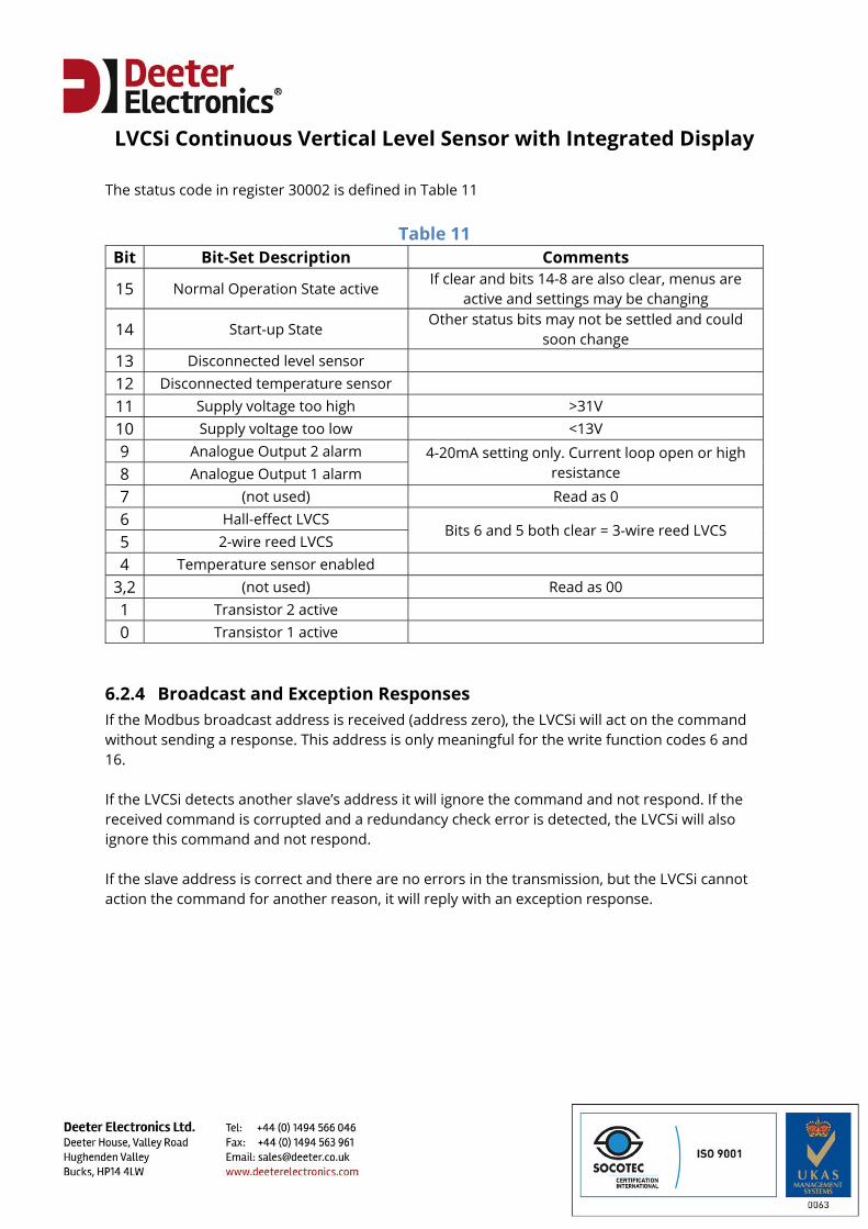
The status code in register 30002 is defined in Table 11
Table 11 Bit Bit-Set Description Comments
15 Normal Operation State active If clear and bits 14-8 are also clear, menus are
active and settings may be changing
14 Start-up State Other status bits may not be settled and could
soon change 13 Disconnected level sensor 12 Disconnected temperature sensor 11 Supply voltage too high >31V 10 Supply voltage too low <13V 9 Analogue Output 2 alarm 4-20mA setting only. Current loop open or high
resistance 8 Analogue Output 1 alarm 7 (not used) Read as 0 6 Hall-effect LVCS
Bits 6 and 5 both clear = 3-wire reed LVCS 5 2-wire reed LVCS 4 Temperature sensor enabled
3,2 (not used) Read as 00 1 Transistor 2 active 0 Transistor 1 active
6.2.4 Broadcast and Exception Responses If the Modbus broadcast address is received (address zero), the LVCSi will act on the command without sending a response. This address is only meaningful for the write function codes 6 and 16. If the LVCSi detects another slave’s address it will ignore the command and not respond. If the received command is corrupted and a redundancy check error is detected, the LVCSi will also ignore this command and not respond. If the slave address is correct and there are no errors in the transmission, but the LVCSi cannot action the command for another reason, it will reply with an exception response.
LVCSi Continuous Vertical Level Sensor with Integrated Display
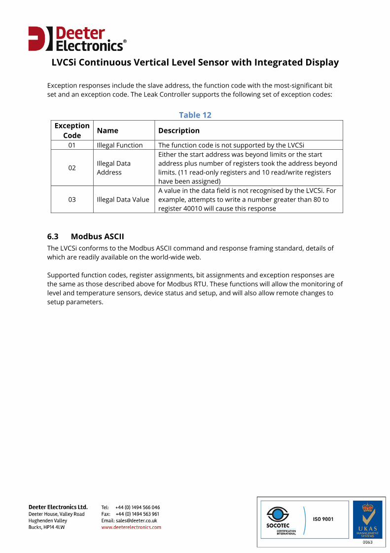
Exception responses include the slave address, the function code with the most-significant bit set and an exception code. The Leak Controller supports the following set of exception codes:
Table 12 Exception
Code Name Description
01 Illegal Function The function code is not supported by the LVCSi
02 Illegal Data Address
Either the start address was beyond limits or the start address plus number of registers took the address beyond limits. (11 read-only registers and 10 read/write registers have been assigned)
03 Illegal Data Value A value in the data field is not recognised by the LVCSi. For example, attempts to write a number greater than 80 to register 40010 will cause this response
6.3 Modbus ASCII The LVCSi conforms to the Modbus ASCII command and response framing standard, details of which are readily available on the world-wide web. Supported function codes, register assignments, bit assignments and exception responses are the same as those described above for Modbus RTU. These functions will allow the monitoring of level and temperature sensors, device status and setup, and will also allow remote changes to setup parameters.
LVCSi Continuous Vertical Level Sensor with Integrated Display
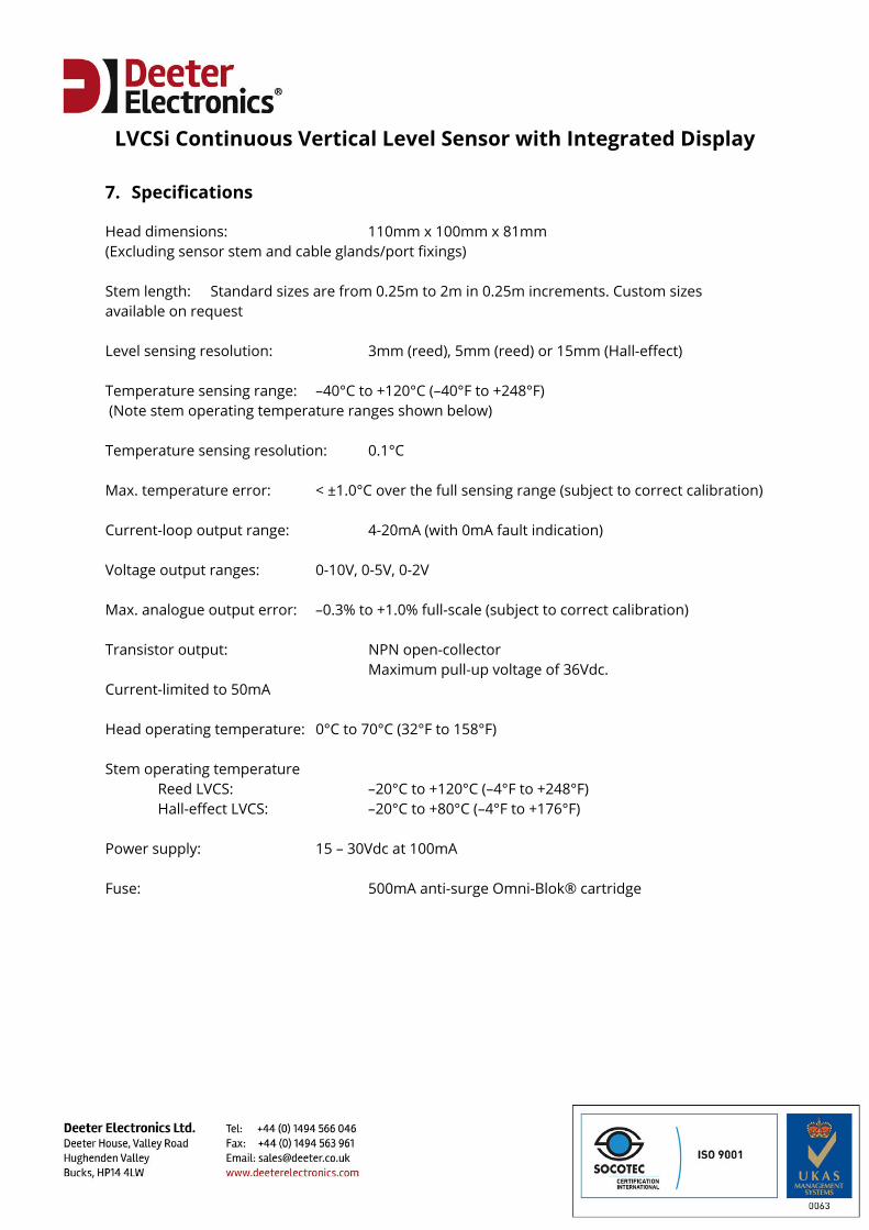
7. Specifications
Head dimensions: 110mm x 100mm x 81mm (Excluding sensor stem and cable glands/port fixings) Stem length: Standard sizes are from 0.25m to 2m in 0.25m increments. Custom sizes available on request Level sensing resolution: 3mm (reed), 5mm (reed) or 15mm (Hall-effect) Temperature sensing range: –40°C to +120°C (–40°F to +248°F) (Note stem operating temperature ranges shown below) Temperature sensing resolution: 0.1°C Max. temperature error: < ±1.0°C over the full sensing range (subject to correct calibration) Current-loop output range: 4-20mA (with 0mA fault indication) Voltage output ranges: 0-10V, 0-5V, 0-2V Max. analogue output error: –0.3% to +1.0% full-scale (subject to correct calibration) Transistor output: NPN open-collector Maximum pull-up voltage of 36Vdc. Current-limited to 50mA Head operating temperature: 0°C to 70°C (32°F to 158°F) Stem operating temperature Reed LVCS: –20°C to +120°C (–4°F to +248°F) Hall-effect LVCS: –20°C to +80°C (–4°F to +176°F) Power supply: 15 – 30Vdc at 100mA Fuse: 500mA anti-surge Omni-Blok® cartridge