Luxor Surgical Technique - az621074.vo.msecnd.net
50
Luxor ® Surgical Technique LITe ® Less Invasive Technologies • Minimally invasive procedures • Luminated expandable oval retractor • Complete visualization and working space
Transcript of Luxor Surgical Technique - az621074.vo.msecnd.net

Luxor®Surgical Technique
LITe®
Less Invasive Technologies
• Minimally invasive procedures
• Luminated expandable ovalretractor
• Complete visualization andworking space


LuxorSurgical Technique
Table of Contents
Introduction . . . . . . . . . . . . . . . . . . . . . . . . . . . . . . . . . . . . . . . . . . . . . . . . . . . . . . . . . . . .4Key Design Features . . . . . . . . . . . . . . . . . . . . . . . . . . . . . . . . . . . . . . . . . . . . . . . . . . . . . .5Patient Positioning . . . . . . . . . . . . . . . . . . . . . . . . . . . . . . . . . . . . . . . . . . . . . . . . . . . . . . .6Arm Assembly Positioning . . . . . . . . . . . . . . . . . . . . . . . . . . . . . . . . . . . . . . . . . . . . . . . .6Lighting Preparation . . . . . . . . . . . . . . . . . . . . . . . . . . . . . . . . . . . . . . . . . . . . . . . . . . . . .7Establishing Access . . . . . . . . . . . . . . . . . . . . . . . . . . . . . . . . . . . . . . . . . . . . . . . . . . . . . . .8Markings . . . . . . . . . . . . . . . . . . . . . . . . . . . . . . . . . . . . . . . . . . . . . . . . . . . . . . . . . . . . . . .8Initial Dilator Insertion . . . . . . . . . . . . . . . . . . . . . . . . . . . . . . . . . . . . . . . . . . . . . . . . . .10Subsequent Dilator Insertion . . . . . . . . . . . . . . . . . . . . . . . . . . . . . . . . . . . . . . . . . . . . .12Retractor Assembly . . . . . . . . . . . . . . . . . . . . . . . . . . . . . . . . . . . . . . . . . . . . . . . . . . . . .13Retractor Insertion . . . . . . . . . . . . . . . . . . . . . . . . . . . . . . . . . . . . . . . . . . . . . . . . . . . . . .15Retractor Variable Opening/Closing Mechanism . . . . . . . . . . . . . . . . . . . . . . . . . . . . .16Disc Preparation and Removal . . . . . . . . . . . . . . . . . . . . . . . . . . . . . . . . . . . . . . . . . . . .18Disc Preparation and Removal Continued . . . . . . . . . . . . . . . . . . . . . . . . . . . . . . . . . .20Interbody Fusion . . . . . . . . . . . . . . . . . . . . . . . . . . . . . . . . . . . . . . . . . . . . . . . . . . . . . . .21Graft Insertion . . . . . . . . . . . . . . . . . . . . . . . . . . . . . . . . . . . . . . . . . . . . . . . . . . . . . . . . .22Screw Insertion: Cannulated . . . . . . . . . . . . . . . . . . . . . . . . . . . . . . . . . . . . . . . . . . . . . .23Screw Insertion: Non-Cannulated . . . . . . . . . . . . . . . . . . . . . . . . . . . . . . . . . . . . . . . . .31Rod Insertion . . . . . . . . . . . . . . . . . . . . . . . . . . . . . . . . . . . . . . . . . . . . . . . . . . . . . . . . . .33Blocker Insertion . . . . . . . . . . . . . . . . . . . . . . . . . . . . . . . . . . . . . . . . . . . . . . . . . . . . . . .37Compression . . . . . . . . . . . . . . . . . . . . . . . . . . . . . . . . . . . . . . . . . . . . . . . . . . . . . . . . . . .39Construct Tightening . . . . . . . . . . . . . . . . . . . . . . . . . . . . . . . . . . . . . . . . . . . . . . . . . . . .40Closure . . . . . . . . . . . . . . . . . . . . . . . . . . . . . . . . . . . . . . . . . . . . . . . . . . . . . . . . . . . . . . .41Contralateral Side . . . . . . . . . . . . . . . . . . . . . . . . . . . . . . . . . . . . . . . . . . . . . . . . . . . . . . .41Catalog . . . . . . . . . . . . . . . . . . . . . . . . . . . . . . . . . . . . . . . . . . . . . . . . . . . . . . . . . . . . . . .42Removal or Revision Procedures . . . . . . . . . . . . . . . . . . . . . . . . . . . . . . . . . . . . . . . . . .46Notes . . . . . . . . . . . . . . . . . . . . . . . . . . . . . . . . . . . . . . . . . . . . . . . . . . . . . . . . . . . . . . .47

LuxorSurgical Technique
Acknowledgments
Stryker Spine wishes to thank the global Luxor Surgeon Panel for their dedication tothe development of the Luxor System.
Introduction
The objective of Stryker Spine Less Invasive Technologies (LITe) is to replicate the clinical results of the corresponding open procedure. What sets the minimallyinvasive procedures apart from open procedures is that while delivering similar clinical results, these procedures may offer reduced intraoperative blood loss*,reduced post operative mobilization times*, and minimized postoperative consumption of orally administered narcotics*.
The Luxor Retractor, part of the LITe platform, was designed to provide access to the thoracic and lumbar spine from a posterior approach via a small incision. The oval design of Luxor® reduces the medial/lateral muscle retraction seen in somecircular retractors, while providing more working space at the level of the incision.
Important
This Surgical Technique sets forth detailed, recommended procedures for using the Luxor System. It offers guidance that you should heed but, as with any suchtechnical guide, each surgeon must consider the particular needs of each patient and make appropriate adjustments when necessary and as required.
Always refer to the package insert, product label and/or instructions before using any Stryker implant or instrument.
Note: No acid or alkaline solvents should be used in the cleaning of anodized components.
Note: Upon the completion of each surgical procedure, use adequate suction and irrigation to ensure the removal of any existing non-implantable materials.
Note: This is intended as a guide only. There are multiple techniques, and as withany surgical procedure, a surgeon should be thoroughly trained before proceeding.
*Data on file at Stryker Spine4

Key Design Features
Radiolucent
u Complete visualization of anatomical landmarks
Silicon sleeve & Anatomical blades
u To prevent tissue from entering surgical site
Cobb-style initial dilator
u Facilitates tissue dissection while incorporating insertion safety
Large distal span
u Maximizes access at surgical site
Oval design
u Maximizes working & visualizations channels while minimizing tissue damage
Thin, shadowless lighting component
u Continuous panoramic lighting that conforms to surgical site
Reliance LITeDecompression Instruments
u Bayoneted
u Non-reflective coating
u Thinner shaft profiles
u Increased working shaft length
Fixation Instruments
u Accommodates Cannulated and Non-cannulated screws
u Rod insertion
u Blocker insertion
u Construct adjustment and final tightening
Key Design
Features
5

Figure 1
Figure 2
Figure 3
Patient Positioning
Luxor can be used under local, epidural, spinal or general anesthesia. General anesthesia is commonly used since it is the most comfortable for the patient and allows immediate postoperativeneurological assessment.
u The patient is prepped and draped in the usual sterile manner for posterolateral fusion withpedicle screw fixation.
6
Arm Assembly Positioning
The Mediflex Flex Arm Post (48250240) mounts to thehospital bed rail. Check compatibility of the MediflexFlex Arm Post to the hospital bed prior to surgery.
u Mount the Arm Post to the bed rail on the oppositeside of the surgeon near the patient’s hip.
u Turn the Arm Post locking mechanism clockwise tosecure it to the bed.
u Once the Arm Post is secure, attach the Snake Arm(48250230) to the Arm Post and lock into place.
u The Snake Arm should be positioned to lie acrossthe patient and wrap in front of the surgeon.
Note: The Snake Arm should be properly reset andlubricated between uses.
Note: For additional information, see the Mediflex FlexArms Surgical User’s Manual.
Note: When using a Jackson Table, an OSI Adapter is needed to mount the Arm Post to the table. Options are:
OSI Retractor Adapter PN 5888OSI Slide Rail Adapter PN 5855-830
LuxorSurgical Technique

Figure 4
Instrument Bar
7
Lighting Preparation
u Determine the type of light source available in the OR.
u Choose the corresponding Luxor Lightsource Adapter:
• Stryker / ACMI / Zimmer Lightsource Adapter (233-050-071)
• Storz Lightsource Adapter (233-050-073)
• Olympus Lightsource Adapter (233-050-072)
• Wolf / Dyonics Lightsource Adapter (233-050-074)
u Attach the Universal Light Cable (48250215) to the appropriateAdapter and insert into the light source.
u Attach the other end of the Universal Light Cable to the LightingComponent (48250210).
u Turn on the light source power to verify light output.
Note: the Universal Light Cable is made of clear fiber optics. This isdesigned to easily identify broken fibers. If light output is low thisinstrument may need to be replaced.
Note: The Lighting Component is a single use instrument.Patient
Prep
48250240Arm Post
48250230Snake Arm
48250215Universal Light Cable
48250210Lighting Component
233-050-071 - Stryker/ACMI/Zimmer233-050-073 - Storz233-050-072 - Olympus233-050-074 - Wolf/DyonicsLightsource Adapters

Establishing Access
A/P images are used to confirm placement of the Luxor System.
The Retractor Base is delivered via a dilation system atapproximately the same angle as the pedicle screws areto be inserted.
Upon insertion, the Luxor retractor exposes portions ofthe lamina, facet joints, and transverse process.
The following steps are taken to assure the correct positioning of the Luxor System.
8
Markings
u Using A/P imaging, place the Guide Pin (48250010)transversely across the mid-line of the cephalad pedicles.
u Draw a line extending several inches lateral to thepedicles.
LuxorSurgical Technique
Figure 5

Instrument Bar
9
u Repeat for the caudal pedicles.
Figure 6
Patient
Prep
48250010Guide Pin

Figure 7
Figure 8
Carefully determine the appropriate entry point andtrajectory for the Luxor.
u For decompression, the entry point is approximately2cm off mid-line with a more medial trajectory.
u For pedicle screws, the entry point is approximately4cm off mid-line with a more lateral trajectory.
Note: The entry point is typically at or cephalad to theaccessory process (AP) on the transverse process.
u A 3.5cm incision parallel to the spine is made at thepuncture site.
u Incise the fascia to make tissue dilation easier.
Note: For procedures not requiring distal expansion ofthe retractor, a 3.0cm incision can be used for insertion.
Note: If tissue dilation is difficult increase the fascialincision.
10
Initial Dilator Insertion
u Place the cobb style Initial Dilator (48250016)through the incision.
u Advance the Dilator through the tissue while directing it toward the inferior aspect of the superiorlamina under lateral imaging.
u The Dilator is advanced through the lumbodorsalfascia.
u Location of the cobb style Initial Dilator is confirmed using imaging.
u Note the depth marking of the Dilator in relation tothe skin.
The Dilators have depth markings (40, 50, 60, 70, 80,90, 105, 120mm) laser etched which correlate to retractor blade lengths.
u Choose a Retractor Blade length (48250(040)-(120))based on where the top of the skin meets the Dilator.
Note: If the skin is between two markings on theDilator choose the next longest Blade.
LuxorSurgical Technique

Figure 9
Instrument Bar
11
u Use the cobb style Initial Dilator to palpate the laminain both the sagittal and transverse planes. This confirmsan appropriate approach laterally.
u The tip of the Dilator is used to sweep the paraspinalmusculature off the laminar edge.
Note: The Dilator (22mm width) is designed not to enterthe intralaminar space when oriented cephalo-caudal.
Note: By keeping the Dilator tip in the subperiosteal space,the dissection is essentially bloodless.
Note: Feel, fluoroscopy, anatomical knowledge, review of preoperative images, and partial visualization may allcontribute towards desired instrument placement accuracy.
Note: Great care must be taken to avoid penetration of theligamentum flavum and inadvertent dural puncture withpossible nerve injury or spinal fluid leak.
Note: If using the Guide Pin do not direct it lateral to thelamina or facet, which risks injury to the nerve root ordeeper structures.
Note: To ensure that the Guide Pin was not bent during aprior surgical procedure, pass the Guide Pin through thecannulation in the cobb style Initial Dilator. This activity confirms that the Guide Pin is not bent, and reduces therisk of the Guide Pin being advanced forward into the canal space when used through the cobb style Initial Dilatorduring the dilation process.
Dilation
Insertion
48250016Cobb Style Initial Dilator
48250040 - 40mm48250050 - 50mm48250060 - 60mm48250070 - 70mm48250080 - 80mm48250090 - 90mm48250105 - 105mm48250120 - 120mmRetractor Blades

Figure 10
Figure 11
Figure 12
Subsequent Dilator Insertion
Option 1: Sequential Dilators
u Slide the 2nd (48250012), 3rd (48250013), 4th (48250014)and 5th (48250015) Dilators to sequentially penetrateand gently dissect soft tisue down to the lamina.
12
u Remove the previous Dilator after inserting the larger one.
Note: Larger diameter Dilators may be used to probeand identify the anatomy.
Note: Use fluoroscopic images to confirm the placement of the final Dilator on the superior facet.
LuxorSurgical Technique
Option 2: Cannulated Blunt Dissector
u Slide the Cannulated Blunt Dissector (48250019)over the Initial Dilator. The single bar should beon the proximal end.
u Remove the Cannulated Blunt Dissector and re-insert with the double bar on the proximal end.
u Use the Cannulated Blunt Dissector to penetrateand gently spread and dissect soft tissue down to the lamina.
u Use imaging to confirm the placement of the BluntDissector on the superior facet.
Note: Proximal and distal ends of the cannulated bluntdissector are identified as follows:
1 bar denotes the proximal end. 2 bars denote the distal end.

Figure 13
Instrument Bar
13
Dilation
Insertion
Figure 14
Retractor Assembly
Assemble each Retractor “Blade” into the Retractor “Base”(48250030)
1. Orient the Base so that the variable driving screw and post are pointing up.
2. Align the hole in the proximal end of the Blade with the pin in the Base.
3. Lightly squeeze the Blade on the proximal edges and insert the Blade into the Base.
48250019Cannulated Blunt Dissector
48250030Retractor Base
48250040 - 40mm48250050 - 50mm48250060 - 60mm48250070 - 70mm48250080 - 80mm48250090 - 90mm48250105 - 105mm48250120 - 120mmRetractor Blades
48250012 - #248250013 - #348250014 - #448250015 - #5Dilators

Figure 15
Figure 16
Figure 17
4. Release the Blade so that it engages the Base.
5. The cutouts at the top of the Blade should snapinto the rectangular features in the Base.
6. Repeat the process for the second Blade.
Note: If a side of the Blade does not engage the Base,push on the 1mm edge of the Blade that is not engagedtoward the cephalo-caudal orientation of the Base.
Note: The Blades and Base are color coded. Match theappropriate Blade color with the corresponding Basecolor during assembly.
14
Note: In cases where the Retractor cannot be actuateddue to docking on bone, using Blades of different length is recommended.
Note: The Silicon Sleeve may need to be cut or altered to accommodate the varying blade lengths chosen.
Note: The sterile Sleeve should be cut with a sterile cutting instrument prior to assembly onto the Retractor .
Note: No jagged edges or visible silicon fragments shouldbe present on the Sleeve when introducing the Retractorassembly into the incision.
u Based on the Blade length, obtain the correspondingSilicon Sleeve (48251(040)-(120).
u With the Retractor in the closed state, dip the Blades in a saline bath.
u Slowly slide the corresponding Silicon Sleeve onto the Blades until it contacts the Base.
Note: The Silicon Sleeve is a single use instrument.
Note: The Silicon Sleeve should be slightly longer thanthe longest Blade being used.
LuxorSurgical Technique

Figure 18
Instrument Bar
15
u Insert the Lighting Component into the RetractorBase. The Lighting Component should be insertedbetween the Retractor Blade and Silicon Sleeve.
u The Lighting Component is inserted until the black baron the Component is even with the Retractor Base.
u The Lighting Component should be oriented so thatthe “Stryker LITe” logo is facing up.
Figure 19
Retractor Insertion
u Slide the closed Retractor assembly over the BluntDissector with the variable drive screw and postpositioned laterally.
u Dock the Retractor on the lamina.
Retractor
Insertion
48251040 - 40mm48251050 - 50mm48251060 - 60mm48251070 - 70mm48251080 - 80mm48251090 - 90mm48251105 - 105mm48251120 - 120mmSilicone Sleeve
48250210Lighting Component
48250030Retractor Base
48250019Cannulated Blunt Dissector

Figure 20
Figure 21
u Attach the Snake Arm to the Retractor Base.
u Lock the Snake Arm to the Retractor Base post byturning the collet.
u Secure the Arm Assembly by tightening the knobs.
u Remove the final Dialator. This establishes an oval operative corridor to the lamina and interlaminar space.
u Use imaging to confirm appropriate positioning.
Note: If repositioning of the Retractor is necessary to expose the laminar edge, use the Driver (48250200)to collapse the Retractor. The Retractor can then bemoved or angled over the pathology using the cobbstyle Initial Dilator. Once in the proper location, theArm Assembly is tightened.
16
Retractor Variable Opening/ClosingMechanism
u Insert the Driver (48250200) into the post of theRetractor Base and screw down (clockwise) the variable drive screw to expand the distal end of theRetractor Blades.
u If necessary, gently rock the Retractor Base in thecephalo-caudal direction during expansion.
LuxorSurgical Technique

Figure 22
Instrument Bar
17
u Confirm expansion and position of the Luxor Systemwith imaging.
Note: Distal opening of the Retractor is dependant on theBlade length. There is a mechanical stop in the Retractorbase with a maximum opening of 22.5 degrees. This correlates to:
Retractor
Insertion
40 68 65
50 76 70
60 89 80
70 91 90
80 89 80
90 98 90
105 91 90
120 85 80
Blade Retractor MaximumLength Distal Span Rod
with Silicon Length(mm) (mm) (mm)
48250230Snake Arm
48250030Retractor Base
48250200Driver
48250019Cannulated Blunt Dissector

1818
LuxorSurgical Technique
Disc Preparation and Removal
Luxor System offers a comprehensive set of Reliance LITe decompressioninstruments. This Reliance LITe set consists of:
u Penfield Elevators: Inspection of the surgical site between dura and bone.
u Nerve Hooks: Retract nerve during surgical procedure. Blunt tip to helpprotect nerve.
u Nerve Retractors: Retract compressed nerve root away from disc space.
u Nerve Probes: Inspection of the surgical site. The ball tip helps to prevent damage of the nerve.
u Woodson Probes: Exploration of the disc space.
u Suction Tips: Provide suction capabilities to evacuate fluid and debris from surgical site.
u Kerrison Rongeurs: Remove disc material, cartilage and hard connective tissue.
u Sypert Rongeur: Remove hard connective tissue. Instrument designed exclusively for use through the Luxor™ Retractor.
u Bovie: Dissect soft tissue.
u Bi-Polar: Dissect soft tissue.
Penfield Bayoneted Sypert Rongeur Nerve Hook Bayoneted, Woodson Probe Bayoneted

1919
Disc Prep
and Removal
These instruments are designed with:
u Bayoneted working shafts provide greater visibility while working through theRetractor.
u Working lengths of the 16cm or more for surgical procedures in the lower posterior thoracic and lumbar spine.
u Non-reflective coating to further increase visibility by reducing glare, whileworking through the Retractor.
u Handle profiles and shaft diameters minimized to provide greater visibility.
u Tips rounded for safety.
Ball Probe Bayoneted Nerve Root Retractor Suction Tip with Bend Micro Scissor

Figure 23
Figure 24
Figure 25
Disc Preparation and RemovalContinued
u Identify the offending disc material.
u Enter the disc space at the vertebral margins.
u Resect the posterior lip of the vertebral body. This will simultaneously help free the cartilagenous endplate and provide direct entry to the disc space.
20
u Remove the offending disc material with a SypertRongeur (48247001).
u Intradiscal and extradiscal work can be executed, asone would normally perform during a microdiscectomy.
u The nerve root and spinal canal are explored toensure the decompression is complete.
u Once the nerve root is decompressed, irrigate thedisc space thoroughly.
LuxorSurgical Technique

Figure 26
Instrument Bar
21
Interbody Fusion
A shaver (TPS Saber; Stryker Endoscopy) is ideal to freethe cartilagenous endplates while preserving the bonyendplate.
48247001Sypert Ronguer
Figure 27
If an Interbody Fusion is to be performed, complete thediscectomy, leaving the anterior and lateral aspects ofthe annulus intact.
u Prepare the endplate for the interbody fusion.
Disc Prep
and Removal

Figure 28
Figure 29
Figure 30
Graft Insertion
u Once the disc space is meticulously prepared, insertcancellous bone into the disc space using angled andstraight forceps.
22
u Subsequently, use available bone tamps to impact thecancellous bone. The anterior longitudinal ligamentand remaining annulus will contain the graft.
u Insert the allograft. Carefully use an angledosteotome or bone tamp to slide the allograft. The chamfered edge facilitates this maneuver.
u Pack additional cancellous bone medial to the firstgraft, then insert the second graft.
u To achieve a posterolateral fusion, decorticate thefacet, pars, transverse processes and sacral ala using aburr, chisels, curettes, kerrisons, and/or rongeurs inthe normal manner.
u Place the bone graft over the decorticated bone inthe usual manner.
LuxorSurgical Technique

Figure 31
Instrument Bar
23
u Insert the Jam Shidi 48237 (105), (110), (115), (135)through the Luxor Retractor to the intersection ofthe facet and transverse process.
u Confirm that the appropriate pedicle starting placehas been determined using both A/P and lateralimages.
Pedicle
Prep
Screw Insertion: Cannulated
The Luxor System is used in conjunction withStryker Spine systems (i.e., Xia Precision System,Techtonix). See the appropriate Surgical Techniquefor additional information and device package insertfor indications, contraindications, warnings &precautions.
10 Gauge, 9 inch 4823711010 Gauge, 5 inch 4823710511 Gauge, 5 inch 4823711513 Gauge, 5 inch 48237135Jam Shidi

Figures 33A & 33B
Figures 34A & 34B
Figure 32
Use the Jam Shidi needle to gain access to the pedicle.
u After placing the Jam Shidi at the intersection of thefacet and the transverse process, the needle may beadvanced partially through the pedicle using theSlap Hammer (48237120).
LuxorSurgical Technique
u As the pedicle is navigated with the Jam Shidi, itshould approach the medial wall of the pedicle onthe A/P view and should approach the base of thepedicle on the lateral view.
u When the needle reaches the medial wall on the A/Pview, verification needs to be performed in thelateral view to ensure the needle is past the base ofthe pedicle.
24

Figure 35
Instrument Bar
25
u Remove the inner trocar of the Jam Shidi.
Figure 36
u The removal of the Jam Shidi inner trocar allows the K-Wire(Sharp - 48230230, Blunt - 48230231) to be inserted into thepedicle.
u Caution should be practiced with regards to the position of the K-Wire in order to avoid the advancement of the K-Wire.
Note: The K-Wire is 1.2mm in diameter.
Note: The K-Wire is a single use instrument.
Pedicle
Prep
48237120Slap Hammer
Sharp 48230230Blunt 48230231K-Wire
10 Gauge, 9 inch 4823711010 Gauge, 5 inch 4823710511 Gauge, 5 inch 4823711513 Gauge, 5 inch 48237135Jam Shidi
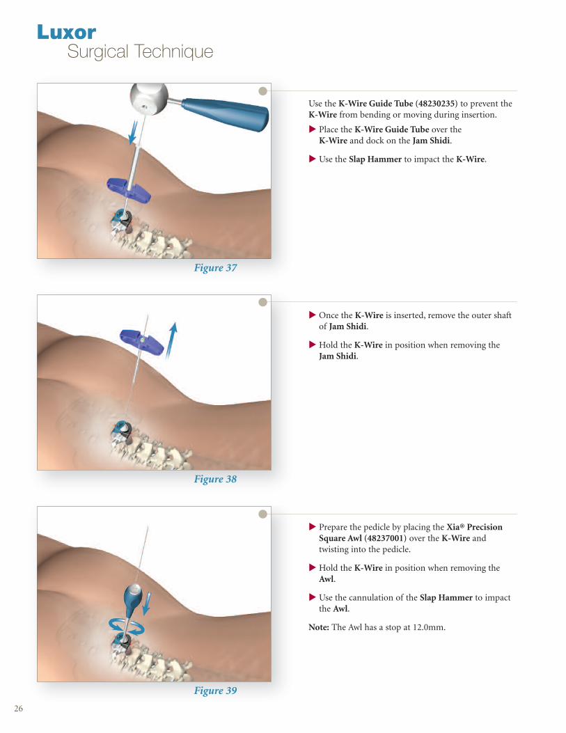
Figure 37
Figure 38
Figure 39
Use the K-Wire Guide Tube (48230235) to prevent theK-Wire from bending or moving during insertion.
u Place the K-Wire Guide Tube over the K-Wire and dock on the Jam Shidi.
u Use the Slap Hammer to impact the K-Wire.
26
u Once the K-Wire is inserted, remove the outer shaftof Jam Shidi.
u Hold the K-Wire in position when removing theJam Shidi.
u Prepare the pedicle by placing the Xia® PrecisionSquare Awl (48237001) over the K-Wire andtwisting into the pedicle.
u Hold the K-Wire in position when removing theAwl.
u Use the cannulation of the Slap Hammer to impactthe Awl.
Note: The Awl has a stop at 12.0mm.
LuxorSurgical Technique

Figure 40
Instrument Bar
27
u If the bone is too hard, the appropriate Tap may be used toprepare the pedicle screw canal.
u The Xia Precision Taps (5.5mm – 48230165, 6.5mm –48230166, 7.5mm – 48230167) are calibrated and laser etchedwith 10.0mm intervals to help indicate the depth at which theTap has been inserted as well as to help determine proper screwlength.
Note: The length of the Taps’ thread is 25mm.
Pedicle
Prep
48237120Slap Hammer
48230235K-Wire Guide Tube
48237001Xia® Precision Square Awl
5.5mm 482301656.5mm 482301667.5mm 48230167Xia® Precision Taps
Sharp 48230230Blunt 48230231K-Wire
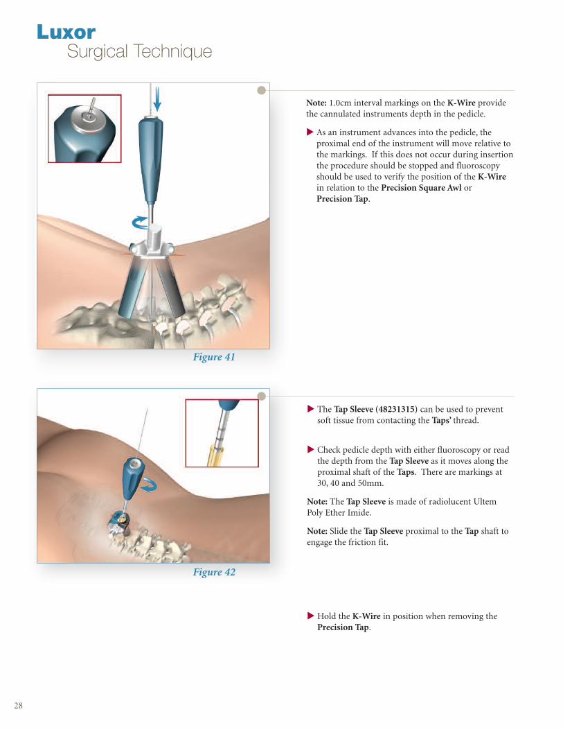
Figure 42
28
u The Tap Sleeve (48231315) can be used to preventsoft tissue from contacting the Taps’ thread.
u Check pedicle depth with either fluoroscopy or readthe depth from the Tap Sleeve as it moves along theproximal shaft of the Taps. There are markings at 30, 40 and 50mm.
Note: The Tap Sleeve is made of radiolucent UltemPoly Ether Imide.
Note: Slide the Tap Sleeve proximal to the Tap shaft toengage the friction fit.
u Hold the K-Wire in position when removing thePrecision Tap.
LuxorSurgical Technique
Figure 41
Note: 1.0cm interval markings on the K-Wire providethe cannulated instruments depth in the pedicle.
u As an instrument advances into the pedicle, the proximal end of the instrument will move relative tothe markings. If this does not occur during insertionthe procedure should be stopped and fluoroscopyshould be used to verify the position of the K-Wirein relation to the Precision Square Awl or Precision Tap.

Instrument Bar
29
Implant
Insertion
Screw Insertion
With the pedicle pathways prepared and proper screw length anddiameter determined, the bone screw is prepared for insertion.
The Xia Precision Polyaxial Screwdriver (48231310) provides a veryrigid connection between the polyaxial bone screws and thescrewdriver. The screwdriver can be attached to any of the cannulatedmodular handles using the quick release mechanism.
u Preload theScrewdriverProtection Sleeve(48237009) ontothe Xia PrecisionScrewdriver.
u Place a XiaPrecision BoneScrew on the distal end of thescrewdriver and lock into place.
Note: The Xia PolyaxialScrewdriver (48041310)may be too short to usewith some of the longerLuxor Retractor Blades.
48231315Tap Sleeve
48231310Xia Precision Polyaxial Screwdriver
48237009Screwdriver Protection Sleeve
48237001Xia Precision Square Awl
5.5mm 482301656.5mm 482301667.5mm 48230167Xia Precision Taps
Sharp 48230230Blunt 48230231K-Wire

Figure 43
Figure 44
Figure 45
Note: With the Xia Precision Bone Screw engaged withthe Precision Screwdriver, the Screwdriver ProtectionSleeve is slid over the proximal end of the screwhead toprevent the screwhead from contacting instrumentsduring implantation.
30
u Place the Xia Precision Bone Screw over the K-Wire and insert into the pedicle.
u After driving the screw assembly into the pedicle,remove the K-Wire to prevent it from advancing.
u Be certain that the screw assembly is not inserted toofar. If the multi-axial head of the Xia PrecisionBone Screw is driven too forcefully against bone, itwill lose its multi-axial capabilities making it difficultto connect the assemblies during subsequent steps.
LuxorSurgical Technique

Figure 46
Instrument Bar
31
u Repeat the process for additional bone screws.
u After inserting additional bone screws, the head ofthe bone screws should be the same height.
Note: The polyaxial bone screws may lock upon insertion. Use the Xia Inserter (48047009) to unlock the heads before introducing the rod.
Figure 47
Screw Insertion: Non-Cannulated
u Use the Bayoneted Awl (48250350) to create a starting hole for the pedicle screw through the LuxorRetractor while not obscuring the surgeon’s view.
Implant
Insertion
48231310Xia Precision Polyaxial Screwdriver
48237009Screwdriver Protection Sleeve
5.5mm 482315(35)-(50)6.5mm 482316(30)-(55)7.5mm 482317(30)-(55)Xia Precision Screw
Sharp 48230230Blunt 48230231K-Wire
48047009Xia Inserter
48250350Bayoneted Awl

Figure 48
Figure 49
u Use the Bayoneted Gear Shift (48250300) to openup the pathway of the pedicle through the LuxorRetractor while not obscuring the surgeon’s view.
u The Gear Shift should contact the bone at all times.
u The correct rotational insertion of the instrumentwill allow the Gear Shift to follow a path of leastresistance without violating the pedicle walls.
32
u Use the Tapered Ball Probe (48250360) to feel thewall of pedicle.
Note: The Tapered Ball Probe has markings at 30, 40,50 and 60mm. Use imaging to determine the appropriate screw length.
Note: To ensure maximum exposure and maneuverability of the Luxor System, decortication canbe facilitated when it is performed after pedicle probingand tapping and prior to screw placement.
See the Xia Spinal System Operative Technique for pedicle screw insertion and package insert for indications, contraindications, warnings & precautions.
LuxorSurgical Technique

Figure 50
Instrument Bar
33
Rod Insertion
u Adjust the bone screw height using the Xia PolyAdjustment Driver (48047033).
Figure 51
u Align the tulip heads of the bone screws using the Screw Head Adjuster (48250310) to facilitate rod insertion.
Implant
Insertion
48250300Bayoneted Gear Shift
48250360Tapered Ball Probe
48047033Xia Poly Adjustment Driver
48250310Screw Head Adjuster

Figure 52
Figure 53
Figure 54
u Use the Rod Calipers (48250320) to determine theappropriate rod length.
1. Adjust the length of the Rod Caliper stemsbased on the corresponding Blade Length.
2. Collapse the Rod Caliper stems and insert intothe Retractor.
Note: When using the Rod Caliper start with armsadjusted to longest blade length being used. Whenusing the 120 mm blades the Rod Caliper arms shouldbe fully extended.
34
3. Dock the Rod Caliper stems onto the mostsuperior and inferior bone screw heads.
4. Twist the nut on the Rod Caliper until slightpressure is felt once the nut contacts theCaliper stems.
5. Remove the Rod Caliper from the Retractor. The stems will spring back to the position insidethe Retractor.
6. Compare the distal span of the Rod Caliperstems with the rod sizes.
Note: Another way to determine rod lengths is by placing a rod of the estimated length in the Rod Holderand holding it over the surgical site. Use imaging tohelp determine the appropriate rod length.
LuxorSurgical Technique

Figure 55
Instrument Bar
35
u Perform rod bending with the Xia French Bender(03807010) to fit the desired spinal contours.
Figure 56Implant
Insertion
The Rod Introducer (48250330) is used through the Retractor to:1. Transition the rod from a vertical to a horizontal orientation 2. Seat the rod into the screw head3. Hold the rod in between screw heads4. Adjust the rod between screw heads5. Remove the rod during the surgical procedure
u Grasp the appropriate length rod in the middle using the Rod Introducer.
u Rotate the rod to a off-vertical orientation.
03807010Xia French Bender
48250320Rod Calipers
48250330Rod Introducer

Figure 57
Figure 58
u Insert the rod through the Retractor Base.
u Place the distal section of the rod into the head ofeither the inferior or superior screw.
36
u Push down on the center of the rod to seat it into theremaining screw heads.
u Adjust the positioning of the rod such that it extendsthrough the screws as seen on the lateral x-ray.
Note: It is recommended not to release the rod fromthe Rod Inserter until the Blockers are inserted into thescrewheads.
LuxorSurgical Technique

Instrument Bar
37
Figure 59
Blocker Insertion
The Inserter (48047009) can help align the Universal Tightener5mm (03807008) and the Blocker (03756230) through theRetractor.
The two engraved lines on the Universal Tightener denote the following:
1. When the lower line is aligned with the top of the Inserter,the Blocker is at the top of the implant.
2. When the upper line is aligned with the top of the Inserter,the Blocker is fully introduced into the implant.
Implant
Insertion
6.0mm 482180(30)-(50)6.0mm 482180(60)-(90)Xia Rad Rod
03756230Xia Blocker
48047009Xia Inserter
03807008Xia Universal Tightener (5mm)

Figure 60
Figure 61
Figure 62
u Insert the Universal Tightener into the Blocker.
38
u Place the Inserter through the Retractor and dock itonto the screw head.
Note: Maintain the position of the rod in the screwheads using the Rod Inserter.
u Slide the Universal Tightener and Blocker throughthe Inserter and secure it in the tulip head of thescrew.
u Rotate the Blocker clockwise to properly seat and temporarily tighten the Blocker.
Note: Do not perform final tightening of the Blockerwith the Inserter in place, or it may not be possible toremove the Inserter.
u Repeat for other bone screws.
u Release the Rod Inserter from the rod once theBlockers are introduced.
Note: The Retractor may need to be repositioned foreasier Blocker insertion by adjusting the Snake Arm ordistal expansion.
Note: Use imaging and monitoring, as preferred, foradded information during bone screw insertion.
Note: For easier blocker insertion, the Retractor mayneed to be repositioned by adjusting the Snake Arm orincreasing the Retractor’s distal blade expansion.
LuxorSurgical Technique

03807019Xia Rod Pusher
Instrument Bar
39
Implant
Insertion
03756230Xia Blocker
48047009Xia Inserter
03807008Xia Universal Tightener (5mm)
Figure 63
Compression
u Lock the 1st Blocker.
u Insert the Compressor (48250370) through the Retractor. The Compressor handle should point medially.
u Insert the Xia Universal Tightener through the Retractor and engage the 2nd Blocker.
u Engage the Compressor on the screwheads and apply force.
u Lock the 2nd Blocker using the Universal Tightener.
u Remove the Universal Tightener.
u Release the force from the Compressor and remove from the Retractor.
Note: Compressor should be stored in the open position while in the container.
48250370Compressor

Figure 64
Construct Tightening
Once the correction procedures have been carried outand the spine is fixed in a satisfactory position, the finaltightening of the Blocker is done by utilizing the Anti-Torque Key (48027000) and the Torque Wrench(03807028).
u Insert the Torque Wrench through the Anti-Torque Key.
u Mate the top of Anti-Torque Key with the bottom ofthe handle of the Torque Wrench.
u Insert the final tightening assembly through theRetractor.
u Visualize the distal end of the Torque Wrenchentering the Blocker.
u Dock the Anti-Torque Key on the Screw.
u Line up the two arrows on the Torque Wrench toachieve the optimum torque of 12Nm for final tightening of the implants.
Note: The Anti-Torque Key must be used for finaltightening. The Anti-Torque performs two importantfunctions:
1. It allows the Torque Wrench to align with theaxis of the tightening axis.
2. It allows one to maximize the torque needed tolock the implant assembly.
Note: If the Anti-Torque Key cannot be easily removedfrom the implant head, the rod may not be fully seated.
u Apply bone graft to the fusion site and close in theusual manner.
Note: For additional information, please refer to theXia Surgical Technique.
LuxorSurgical Technique
Figure 65
40

Figure 67
Instrument Bar
41
Contralateral Side
Move to the opposite side of the patient and repeat the steps of thetechnique on the contralateral side.
It is recommended that a visible inspection of the surgical site be performed followed by irrigation and suction post procedure toinsure that no existing implantable materials are left in-situ.
Figure 66
Closure
u Examine the site for bleeding.
u Close the Retractor Base with the Driver before withdrawing it from theincision. The muscle and fascia close as the retractor is withdrawnthrough the dilated tissues.
u If accessible, close the fascia with one or two interrupted sutures. Thesubcutaneous tissue is closed in an inverted manner. A subcuticular closure is performed. Cover the skin edge with clear waterproofdressing.
Tightening
03807028Xia Torque Wrench
48027000Anti-Torque Key

42
LuxorSurgical Technique
4825000048250000AA
Luxor Retractor TrayLuxor Retractor Tray Insert
48250230 Snake Arm
48250240 Arm Post
48250010 Guide Pin
48250012
48250013
48250014
48250015
Dilator #2
Dilator #3
Dilator #4
Dilator #5
48250016 Cobb Style Initial Dilator
48250019 Cannulated Blunt Dissector
48250030 Retractor Base
4825004048250050482500604825007048250080482500904825010548250120
Set of Retractor Blades 40mmSet of Retractor Blades 50mmSet of Retractor Blades 60mmSet of Retractor Blades 70mmSet of Retractor Blades 80mmSet of Retractor Blades 90mmSet of Retractor Blades 105mmSet of Retractor Blades 120mm
4825104048251050482510604825107048251080482510904825110548251120
Set of Silicon Sleeves 40mmSet of Silicon Sleeves 50mmSet of Silicon Sleeves 60mmSet of Silicon Sleeves 70mmSet of Silicon Sleeves 80mmSet of Silicon Sleeves 90mmSet of Silicon Sleeves 105mmSet of Silicon Sleeves 120mm
Catalog # Description
Instruments
4343
Catalog
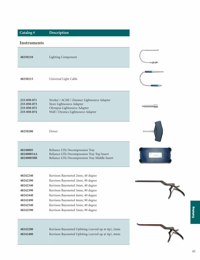
48250210 Lighting Component
48250215 Universal Light Cable
233-050-071233-050-073233-050-072233-050-074
Stryker / ACMI / Zimmer Lightsource AdapterStorz Lightsource AdapterOlympus Lightsource AdapterWolf / Dyonics Lightsource Adapter
48250200 Driver
4824000548240005AA48240005BB
Reliance LITe Decompression TrayReliance LITe Decompression Tray Top InsertReliance LITe Decompression Tray Middle Insert
48242240
48242290
48242340
48242390
48242440
48242490
48242540
48242590
Kerrison Bayoneted 2mm, 40 degree
Kerrison Bayoneted 2mm, 90 degree
Kerrison Bayoneted 3mm, 40 degree
Kerrison Bayoneted 3mm, 90 degree
Kerrison Bayoneted 4mm, 40 degree
Kerrison Bayoneted 4mm, 90 degree
Kerrison Bayoneted 5mm, 40 degree
Kerrison Bayoneted 5mm, 90 degree
48242200
48242400
Kerrison Bayoneted Upbiting (curved up at tip), 2mm
Kerrison Bayoneted Upbiting (curved up at tip), 4mm
Catalog # Description
Instruments
4444
LuxorSurgical Technique
Catalog # Description
Instruments
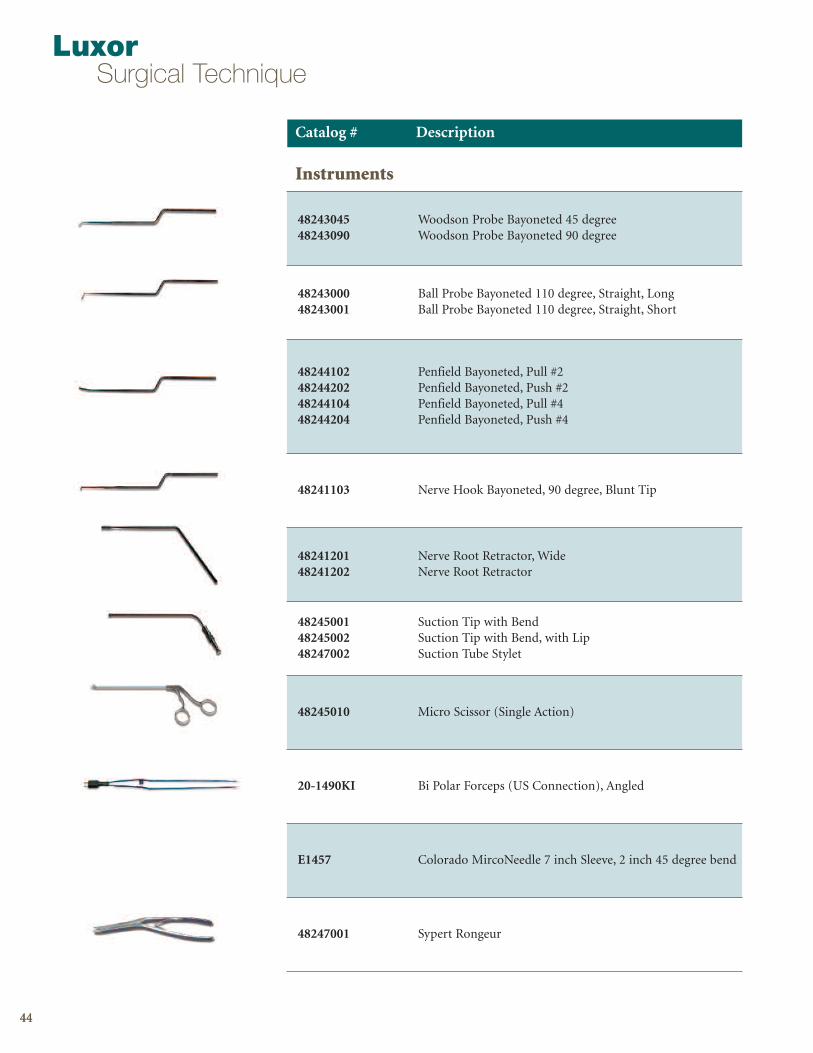
4824304548243090
Woodson Probe Bayoneted 45 degreeWoodson Probe Bayoneted 90 degree
4824300048243001
Ball Probe Bayoneted 110 degree, Straight, LongBall Probe Bayoneted 110 degree, Straight, Short
48244102482442024824410448244204
Penfield Bayoneted, Pull #2Penfield Bayoneted, Push #2Penfield Bayoneted, Pull #4Penfield Bayoneted, Push #4
48241103 Nerve Hook Bayoneted, 90 degree, Blunt Tip
4824120148241202
Nerve Root Retractor, WideNerve Root Retractor
482450014824500248247002
Suction Tip with BendSuction Tip with Bend, with LipSuction Tube Stylet
48245010 Micro Scissor (Single Action)
20-1490KI Bi Polar Forceps (US Connection), Angled
E1457 Colorado MircoNeedle 7 inch Sleeve, 2 inch 45 degree bend
48247001 Sypert Rongeur

4545
Catalog
Catalog # Description
Instruments
4825000148250001A48250001B48250001C
Luxor Fixation Instruments TrayLuxor Fixation Instruments Tray Bottom InsertLuxor Fixation Instruments Tray Middle InsertLuxor Fixation Instruments Tray Top Insert
48250300 Bayoneted Gear Shift
48250310 Screw Head Adjuster
48250320 Rod Calipers
48250330 Rod Introducer
48250350 Bayoneted Awl
48250360 Tapered Ball Probe
48250370 Compressor
48047033 Xia Poly Adjustment Driver
03807008 Xia Universal Tightener (5mm)
48047009 Xia Inserter
03807028 Xia Torque Wrench
03807010 Xia French Bender
48027000 Anti-Torque Key
03807019 Xia Rod Pusher

4646
LuxorSurgical Technique
Removal or Revision Procedures
The spinal implants are temporary internal fixation devices designed to stabilize theoperative site during the normal healing process. After healing occurs, these devicesusually serve no functional purpose and can be removed. Removal may also berecommended in other cases, such as:
Corrosion with a painful reaction
Migration of the implant, with subsequent pain and/or neurological, articularor soft tissue lesions
Pain or abnormal sensations due to the presence of the implants
Infection or inflammatory reactions
Reduction in bone density due to the different distribution of mechanical andphysiological stresses and strains
Bone growth restraint due to the presence of the implants (in pediatric use)
Failure or mobilization of the implant
Standard ancillaries provided by Stryker Spine can be used to remove the implants.Any decision by a physician to remove the internal fixation device should take intoconsideration such factors as the risk to the patient of the additional surgicalprocedure as well as the difficulty of removal. Removal of an unloosened spinalscrew may require the use of special instruments to disrupt the interface at theimplant surface. This technique may require practice in the laboratory before beingattempted clinically. Implant removal should be followed by adequate postoperativemanagement to avoid fracture or re-fracture. Removal of the implant after fracturehealing is recommended. Metallic implants can losen, bend, fracture, corrode, migrate, cause pain or stress shield bone.
s
s
s
s
s
s
s

47
Notes
Disclaimers

4848
Notes
LuxorSurgical Technique


A surgeon must always rely on his or her own professional clinical judgment when deciding whether to use aparticular product when treating a particular patient. Stryker does not dispense medical advice and recommendsthat surgeons be trained in the use of any particular product before using it in surgery.
The information presented is intended to demonstrate the breadth of Stryker product offerings. A surgeon mustalways refer to the package insert, product label and/or instructions for use before using any Stryker product.Products may not be available in all markets because product availability is subject to the regulatory and/or medicalpractices in individual markets. Please contact your Stryker representative if you have questions about theavailability of Stryker products in your area.
Stryker Corporation or its divisions or other corporate affiliated entities own, use or have applied for the followingtrademarks or service marks: LITe, Luxor, Reliance, Stryker, Techtonix, Xia. All other trademarks are trademarks oftheir respective owners or holders.
MILUX-ST-1SC/GS 01/16
Copyright © 2016 StrykerPrinted in USA
Stryker Spine2 Pearl Court Allendale, NJ 07401-1677 USAt: 201-760-8000www.stryker.com