
Luminosity detector at the International Linear...
27
Luminosity detector at the International Linear Collider: Monte Carlo simulations and analysis of test beam data Jonathan Aguilar Thesis supervisor: Dr Bogdan Pawlik Research co-supervisor: Dr hab. inż. Marek Idzik AGH University of Science and Technology Henryk Niewodniczanski Institute of Nuclear Physics - Polish Academy of Sciences February 28, 2012 J. Aguilar (AGH/IFJ-PAN) LumiCal simulations and prototyping February 28, 2012 1 / 20
-
Upload
truongtuyen -
Category
Documents
-
view
218 -
download
0
Transcript of Luminosity detector at the International Linear...
Luminosity detector at the International Linear Collider:Monte Carlo simulations and analysis of test beam data
Jonathan Aguilar
Thesis supervisor: Dr Bogdan PawlikResearch co-supervisor: Dr hab. inż. Marek Idzik
AGH University of Science and TechnologyHenryk Niewodniczanski Institute of Nuclear Physics - Polish Academy of Sciences
February 28, 2012
J. Aguilar (AGH/IFJ-PAN) LumiCal simulations and prototyping February 28, 2012 1 / 20
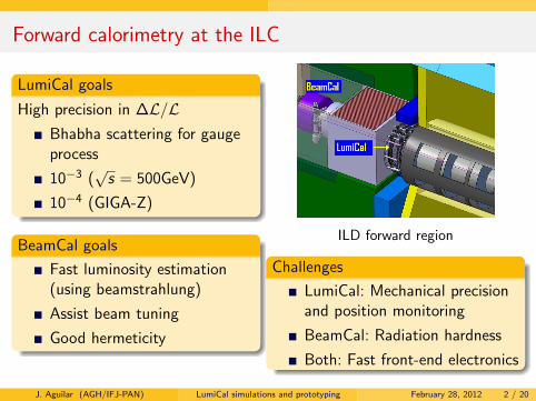
Forward calorimetry at the ILC
LumiCal goals
High precision in ∆L/LBhabha scattering for gaugeprocess
10−3 (√s = 500GeV)
10−4 (GIGA-Z)
BeamCal goals
Fast luminosity estimation(using beamstrahlung)
Assist beam tuning
Good hermeticity
ILD forward region
Challenges
LumiCal: Mechanical precisionand position monitoring
BeamCal: Radiation hardness
Both: Fast front-end electronics
J. Aguilar (AGH/IFJ-PAN) LumiCal simulations and prototyping February 28, 2012 2 / 20
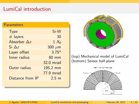
LumiCal introduction
Parameters
Type Si-W# layers 30Absorber ∆z 1 X0Si ∆z 300 µmLayer offset 3.75o
Inner radius 80 mm32.0 mrad
Outer radius 195.2 mm77.9 mrad
Distance from IP 2.5 m
(top) Mechanical model of LumiCal(bottom) Sensor half-plane
J. Aguilar (AGH/IFJ-PAN) LumiCal simulations and prototyping February 28, 2012 3 / 20
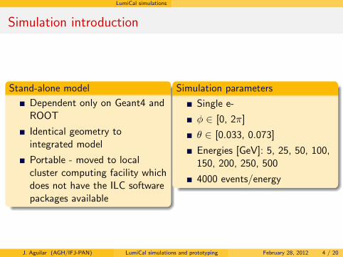
LumiCal simulations
Simulation introduction
Stand-alone model
Dependent only on Geant4 andROOT
Identical geometry tointegrated model
Portable - moved to localcluster computing facility whichdoes not have the ILC softwarepackages available
Simulation parameters
Single e-
φ ∈ [0, 2π]
θ ∈ [0.033, 0.073]
Energies [GeV]: 5, 25, 50, 100,150, 200, 250, 500
4000 events/energy
J. Aguilar (AGH/IFJ-PAN) LumiCal simulations and prototyping February 28, 2012 4 / 20
LumiCal simulations
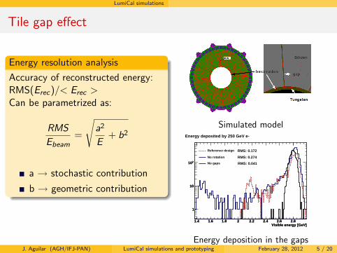
Tile gap effect
Energy resolution analysis
Accuracy of reconstructed energy:RMS(Erec)/< Erec >Can be parametrized as:
RMSEbeam
=
√a2
E+ b2
a → stochastic contribution
b → geometric contribution
Simulated model
Visible energy [GeV]1.4 1.6 1.8 2 2.2 2.4 2.6 2.8
1
10
210
Visible energy [GeV]1.4 1.6 1.8 2 2.2 2.4 2.6 2.8
1
10
210
Energy deposited by 250 GeV e-
Reference design
No rotation
No gaps
RMS: 0.172
RMS: 0.274
RMS: 0.041
Energy deposition in the gapsJ. Aguilar (AGH/IFJ-PAN) LumiCal simulations and prototyping February 28, 2012 5 / 20
LumiCal simulations
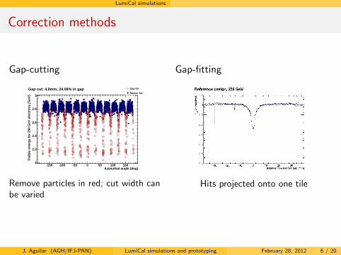
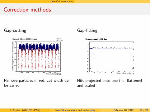
Correction methods
Gap-cutting
Azimuthal angle [deg]-150 -100 -50 0 50 100 150
Vis
ible
en
erg
y fo
r 25
0 G
eV e
lect
ron
s [G
eV]
2
2.2
2.4
2.6
2.8
3
Gap cut: 4.8mm, 24.08% in gap Gap hit
Sensor hit
Remove particles in red; cut width canbe varied
Gap-fitting
Hits projected onto one tile
J. Aguilar (AGH/IFJ-PAN) LumiCal simulations and prototyping February 28, 2012 6 / 20
LumiCal simulations
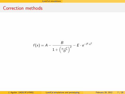
Correction methods
f (x) = A− B
1 +(x−CD
)2 − E · e−F ·x2
J. Aguilar (AGH/IFJ-PAN) LumiCal simulations and prototyping February 28, 2012 7 / 20

LumiCal simulations
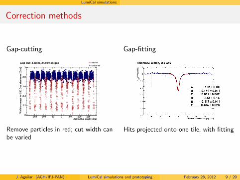
Correction methods
Gap-cutting
Azimuthal angle [deg]-150 -100 -50 0 50 100 150
Vis
ible
en
erg
y fo
r 25
0 G
eV e
lect
ron
s [G
eV]
2
2.2
2.4
2.6
2.8
3
Gap cut: 4.8mm, 24.08% in gap Gap hit
Sensor hit
Remove particles in red; cut width canbe varied
Gap-fitting
Hits projected onto one tile
J. Aguilar (AGH/IFJ-PAN) LumiCal simulations and prototyping February 28, 2012 8 / 20
LumiCal simulations
Correction methods
Gap-cutting
Azimuthal angle [deg]-150 -100 -50 0 50 100 150
Vis
ible
en
erg
y fo
r 25
0 G
eV e
lect
ron
s [G
eV]
2
2.2
2.4
2.6
2.8
3
Gap cut: 4.8mm, 24.08% in gap Gap hit
Sensor hit
Remove particles in red; cut width canbe varied
Gap-fitting
Hits projected onto one tile, with fitting
J. Aguilar (AGH/IFJ-PAN) LumiCal simulations and prototyping February 28, 2012 9 / 20
LumiCal simulations
Correction methods
Gap-cutting
Azimuthal angle [deg]-150 -100 -50 0 50 100 150
Vis
ible
en
erg
y fo
r 25
0 G
eV e
lect
ron
s [G
eV]
2
2.2
2.4
2.6
2.8
3
Gap cut: 4.8mm, 24.08% in gap Gap hit
Sensor hit
Remove particles in red; cut width canbe varied
Gap-fitting
Hits projected onto one tile, flattenedand scaled
J. Aguilar (AGH/IFJ-PAN) LumiCal simulations and prototyping February 28, 2012 10 / 20
LumiCal simulations
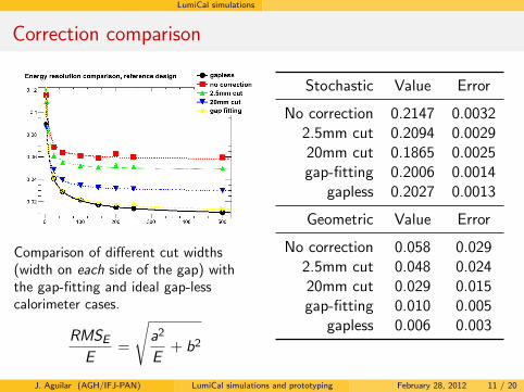
Correction comparison
Comparison of different cut widths(width on each side of the gap) withthe gap-fitting and ideal gap-lesscalorimeter cases.
RMSEE
=
√a2
E+ b2
Stochastic Value Error
No correction 0.2147 0.00322.5mm cut 0.2094 0.002920mm cut 0.1865 0.0025gap-fitting 0.2006 0.0014
gapless 0.2027 0.0013
Geometric Value Error
No correction 0.058 0.0292.5mm cut 0.048 0.02420mm cut 0.029 0.015gap-fitting 0.010 0.005
gapless 0.006 0.003
J. Aguilar (AGH/IFJ-PAN) LumiCal simulations and prototyping February 28, 2012 11 / 20
LumiCal simulations
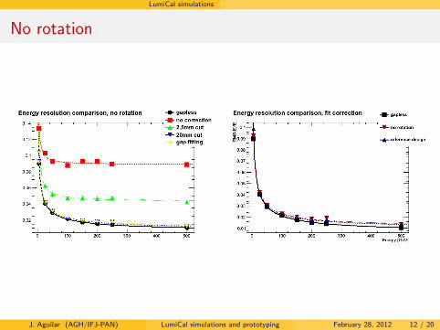
No rotation
J. Aguilar (AGH/IFJ-PAN) LumiCal simulations and prototyping February 28, 2012 12 / 20
LumiCal simulations
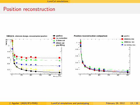
Position reconstruction
J. Aguilar (AGH/IFJ-PAN) LumiCal simulations and prototyping February 28, 2012 13 / 20
Test beams
Test beam introduction
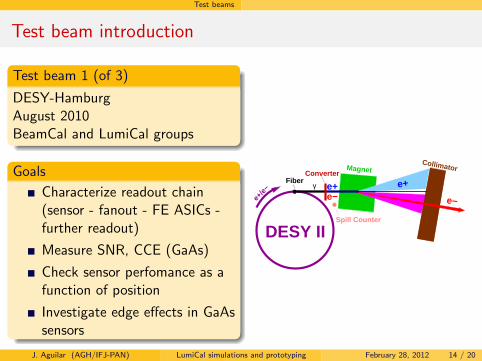
Test beam 1 (of 3)
DESY-HamburgAugust 2010BeamCal and LumiCal groups
Goals
Characterize readout chain(sensor - fanout - FE ASICs -further readout)
Measure SNR, CCE (GaAs)
Check sensor perfomance as afunction of position
Investigate edge effects in GaAssensors
Collimator
Fiberγ
e−
Spill Counter
MagnetConverter
e−
e+e+
DESY II
e+/e−
J. Aguilar (AGH/IFJ-PAN) LumiCal simulations and prototyping February 28, 2012 14 / 20
Test beams SensorMeas
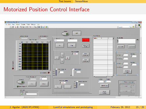
Motorized Position Control Interface
J. Aguilar (AGH/IFJ-PAN) LumiCal simulations and prototyping February 28, 2012 15 / 20
Test beams SensorMeas
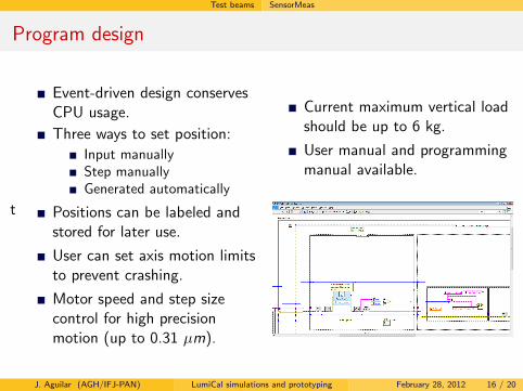
Program design
t
Event-driven design conservesCPU usage.Three ways to set position:
Input manuallyStep manuallyGenerated automatically
Positions can be labeled andstored for later use.
User can set axis motion limitsto prevent crashing.
Motor speed and step sizecontrol for high precisionmotion (up to 0.31 µm).
Current maximum vertical loadshould be up to 6 kg.
User manual and programmingmanual available.
J. Aguilar (AGH/IFJ-PAN) LumiCal simulations and prototyping February 28, 2012 16 / 20
Test beams
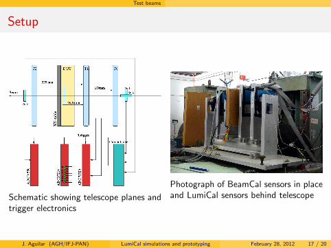
Setup
Schematic showing telescope planes andtrigger electronics
Photograph of BeamCal sensors in placeand LumiCal sensors behind telescope
J. Aguilar (AGH/IFJ-PAN) LumiCal simulations and prototyping February 28, 2012 17 / 20
Test beams Test beam simulation
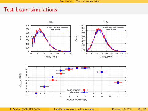
Test beam simulations
0
200
400
600
800
1000
1200
1400
0 5 10 15 20 25 30
Co
un
t
Energy [MIP]
2 X0
measurementsimulation
0
100
200
300
400
500
600
700
800
900
1000
0 5 10 15 20 25 30 35 40
Co
un
t
Energy [MIP]
4 X0
measurementsimulation
1
2
3
4
5
6
7
8
9
10
11
0 1 2 3 4 5 6 7 8 9 10 11 12
<Q
sum
>
[MIP
]
Aborber thickness [X0]
measurementsimulation
J. Aguilar (AGH/IFJ-PAN) LumiCal simulations and prototyping February 28, 2012 18 / 20
Summary
Summary
SimulationsRealistic LumiCal model implemented and simulatedTile gap effect understood and calculated“No-rotation” geometry produces good results, but must beinvestigated further
Test beamSimulation of the test beam good in general, but needs to be refinedX-Y table software implemented and improved over succesive testbeams(Backup slides) Good SNR (∼18)(Backup slides) Low crosstalk even from longest fanout channelsFirst test of readout chain - sensors with FE ASICs - was successful!
Many thanks to the Marie Curie Network on Particle Detectors forfunding this work.
J. Aguilar (AGH/IFJ-PAN) LumiCal simulations and prototyping February 28, 2012 19 / 20

Dziękuję za uwagę!
J. Aguilar (AGH/IFJ-PAN) LumiCal simulations and prototyping February 28, 2012 20 / 20
Backup
Backup slides
Backup
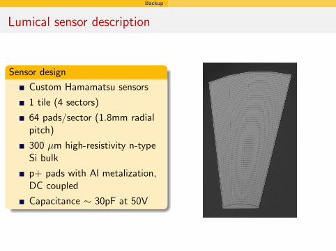
Lumical sensor description
Sensor design
Custom Hamamatsu sensors
1 tile (4 sectors)
64 pads/sector (1.8mm radialpitch)
300 µm high-resistivity n-typeSi bulk
p+ pads with Al metalization,DC coupled
Capacitance ∼ 30pF at 50V
Backup
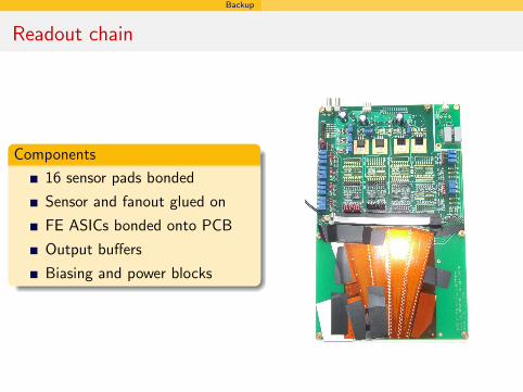
Readout chain
Components
16 sensor pads bonded
Sensor and fanout glued on
FE ASICs bonded onto PCB
Output buffers
Biasing and power blocks
Backup
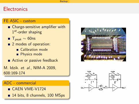
Electronics
FE ASIC - custom
Charge-sensitive amplifier with1st-order shaping
Tpeak ∼ 60ns2 modes of operation:
Calibration modePhysics mode
Active or passive feedback
M. Idzik. et. al., NIM-A 2009,608:169-174
ADC - commercial
CAEN VME-V1724
14 bits, 8 channels, 100 MSps
Backup
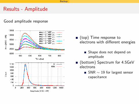
Results - Amplitude
Good amplitude response
(top) Time response toelectrons with different energies
Shape does not depend onamplitude
(bottom) Spectrum for 4.5GeVelectrons
SNR ∼ 19 for largest sensorcapacitance
Backup
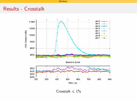
Results - Crosstalk
Crosstalk ¬ 1%
Backup
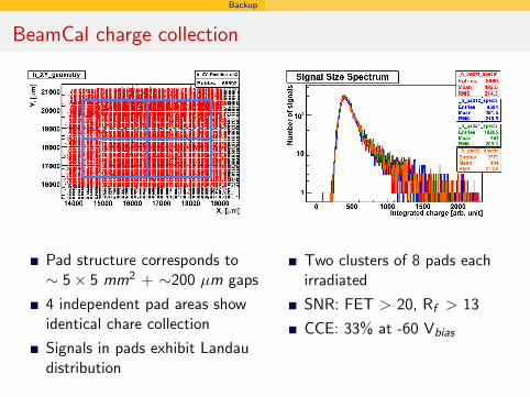
BeamCal charge collection
Pad structure corresponds to∼ 5× 5 mm2 + ∼200 µm gaps
4 independent pad areas showidentical chare collection
Signals in pads exhibit Landaudistribution
Two clusters of 8 pads eachirradiated
SNR: FET > 20, Rf > 13
CCE: 33% at -60 Vbias