LuK Repair Solution for Dry Double clutches...Renault 6-speed gearbox DC4 LuK Repair Solution for...
40
Renault 6-speed gearbox DC4 LuK Repair Solution for Dry Double clutches Fault diagnosis Special tools/Disassembly and assembly
Transcript of LuK Repair Solution for Dry Double clutches...Renault 6-speed gearbox DC4 LuK Repair Solution for...

Renault 6-speed gearbox DC4
LuK Repair Solutionfor Dry Double clutchesFault diagnosisSpecial tools/Disassembly and assembly

2
Copyright ©Schaeffler Automotive Aftermarket GmbH & Co. KG April 2014
The content of this brochure is not legally binding and is solely intended for information purposes. Where legally permissible, all liability on the part of Schaeffler Automotive Aftermarket GmbH & Co. KG devolving in connection with this brochure is excluded.
All rights reserved. Any reproduction, distribution, communication, public reproduction or other publication of this brochure in its entirety or in part is not permitted without prior written consent from Schaeffler Automotive Aftermarket GmbH & Co. KG.

3
Page
1 Diagnostics of double clutch transmission 4
1.1 General notes on testing the system 4
1.2 Wear testing 5
1.3 Visual inspection 5
1.4 Noise 5
1.5 Diagnostics 5
2 Description and scope of the LuK RepSet® 2CT 6
3 Description and scope of the LuK special tools 7
3.1 Basic tool kit 8
3.2 Renault tool kit 10
3.3 Reset tool kit 12
4 Disassembly and assembly of the double clutch 14
4.1 Repair guidelines 15
4.2 Removal of the double clutch 16
4.3 Removal of the engaging system 21
4.4 Installation of the engaging system 24
4.5 Installation of the double clutch 29
4.6 Disabling the transport lock of the double clutch 33
5 Enabling the transport lock of a previously used double clutch 36
Contents
Contents

4
1.1 General notes on testing the system
Before starting repair work on the double clutch, the customer needs to answer some basic questions in order to get as precise a picture of the fault as possible.
If the vehicle is still driveable, we recommend that it is taken for a test drive. The customer should be behind the wheel in order to demonstrate any malfunctions.
Specific questions for the customer:• Whatexactlyisnotworking/whatisthecomplaint precisely?• Whendidtheproblemstart?• Didtheproblemoccursuddenlyordiditdevelop gradually?• Whendoestheproblemoccur? Sporadically, often, always?• Under what driving conditions does the problem occur? E.g. when starting from a standstill, accelerating, slowing down, when cold or at normal operating temperature?• Whatisthemileageofthevehicle?• Isthevehiclesubjectedtounusualstresses? E.g. towing, high payload, frequent mountain driving, being used as a taxi, fleet vehicle, rental car, driving school?• Whatdoesthedrivingprofilelooklike? City vehicle, short trips, long-distance, motorway?• Haverepairsalreadybeenperformedontheclutch/ transmission system? If so, at what mileage? What was the complaint at the time? What repairs were carried out?
General checks to perform on the vehicleThe following items should be checked prior to starting repair work on the vehicle:• ErrorcodeentriesintheECU(engine,transmission, clutch, amenities, CAN-BUS, etc.)• Batterypower
Double clutch, engine side
Double clutch, gearbox side
1 Diagnostics of double clutch transmission
1Diagnosticsofdoubleclutchtransmission

5
Clutch wear cannot be determined by a test drive. The clutch and transmission system has a sophisticated electronic monitoring system, so if the wear limit is reached a warning will appear on the instrument panel.
1.3 Visual inspection
Before any repairs are carried out in the area of the clutch assembly, it should, as a matter of course, be checkedforleaksanddamage.Damageduetobrokenparts or oil leaks due to defective gaskets or o-rings must first be repaired before replacing the clutch. If there is oil on the clutch, it must be replaced.
1.4 Noise
When assessing noises coming from the area of the double clutch during a test drive, it must be ensured that no noises are being generated by surrounding components, such as the exhaust system, heat shields, engine mountings, auxiliary units, etc. The radio, air conditioning and ventilation system should be switched off while diagnosing noises. When in the workshop, a stethoscope can be used to help isolate the source of the noise.
1.2 Wear testing
The gearbox and clutch electronics have a diagnostic function. The contents of the fault memory must be downloaded using a suitable diagnostic device prior to carrying out repair work, and if possible, printed out and kept as a hard copy. The fault memory log provides an initial overview of system errors and serves as a basis for identifying and implementing further repair mea-sures. It also provides valuable data for assessing fault symptoms(importantwhencontactingtheLuKINAFAGservice centre or in the case of warranty).
After completing all work on the double clutch, the clutch electronics must be reset.
Note:If you have any questions about diagnostic and repair work, you can call our Service Center on: +49 6103 753-333.
1.5 Diagnostics

6
WithLuKRepSet® 2CT, Schaeffler Automotive Aftermarketoffers a practical and comprehensive solution. The com-ponents contained in the kit are precisely matched to one another at the factory. This ensures that problems that can occur due to mis-matched components can be prevented from the outset.
TheLuKRepSet®2CT(twinclutchtechnology)includesall of the components necessary to replace the double clutch system. It is recommended that the engagement system is replaced at the same time as the double clutch. After all, it’s likely to suffer wear too.
2 Description and scope of the LuK RepSet® 2CT
7 Engagement bearing for K1 and K28 Retainingring9 Retainingboltsforleveractuators10 Retainingboltsforcentringsleeve11 Retainingboltsforservomotors
1 Doubleclutch 2 Leveractuatorforclutch1(K1)3 ReturnspringsforleveractuatorK1 4 Leveractuatorforclutch2(K2) 5 ReturnspringsforleveractuatorK26 Centring sleeve
2DescriptionandscopeoftheLuKRepSet® 2CT
78
10
11
6
9
2
4
3
5
1

7
3DescriptionandscopeofdeliveryoftheLuKspecialtools
Ifapreviouslyremoveddoubleclutchisreused(forinstance, due to work being carried out on the gearbox gasket), the transport lock must be re-enabled.
Schaeffler Automotive Aftermarket has developed a modular tool system specifically for current and future LuKbranddrydoubleclutchsystems.Themodularunitsare all compatible with one another.
TheLuKspecialtoolisessentialforthecorrectdismant-ling/assemblyoftheRenaultdoubleclutch.Thedoubleclutch must be pulled off from the gearbox input shaft during dismantling, and pressed back on again during assembly. In addition, the return springs must be cor-rectlyadjustedandthetransportlocksonclutchesK1and K2 released following mounting.
3 Description and scope of delivery of the LuK special tools
Note:If you have any questions about the special tools, pleasecallourLuKINAFAGServiceCentreon:+49 6103 753-333.
8
6
5
87
1
910
12
11
2
34
3DescriptionandscopeofdeliveryoftheLuKspecialtools
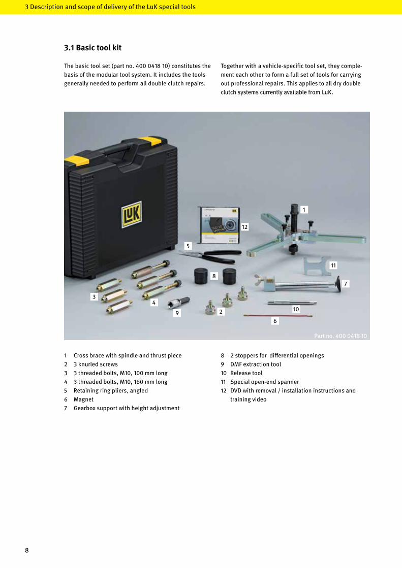
3.1 Basic tool kit
Together with a vehicle-specific tool set, they comple-ment each other to form a full set of tools for carrying out professional repairs. This applies to all dry double clutch systems currently available fromLuK.
Thebasictoolset(part no. 400 0418 10) constitutes the basis of the modular tool system. It includes the tools generally needed to perform all double clutch repairs.
Part no. 400 0418 10
8 2 stoppers for differential openings9 DMFextractiontool10 Releasetool11 Special open-end spanner12 DVDwithremoval/installationinstructionsand training video
1 Cross brace with spindle and thrust piece2 3 knurled screws3 3threadedbolts,M10,100mmlong 4 3threadedbolts,M10,160mmlong5 Retainingringpliers,angled6 Magnet7 Gearboxsupportwithheightadjustment

9
1 2
3
4
5
3.2 Renault tool kit
Thistoolset(part no. 400 0423 10) includes all the tools neededtoperformprofessionalrepairsonaRenaultdrydoubleclutch(6-speedgearboxDC4).Itisintendedtobeusedinconjunctionwiththebasictoolset.
1 3 hooks2 Thrust sleeve installation3 Support sleeve removal4 Lockingpiece5 DVDwithremoval/installationinstructionsand training video
Part no. 400 0423 10
10
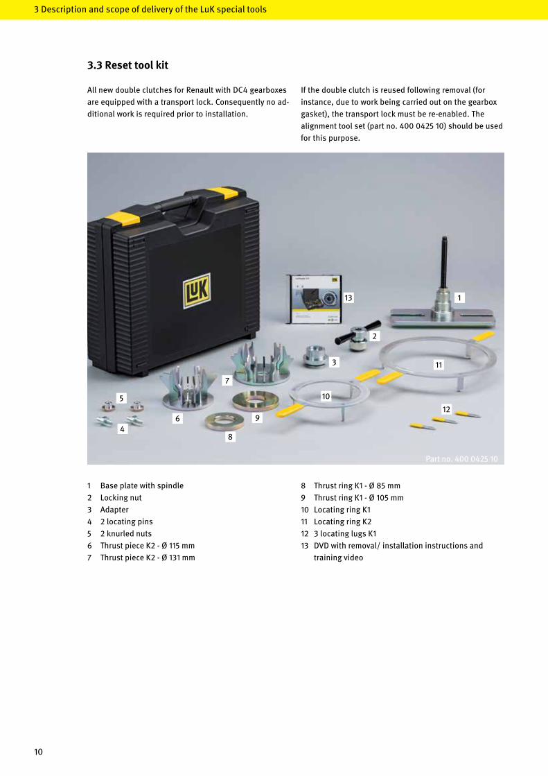
3.3 Reset tool kit
6
5
8
7
1
9
10
12
11
2
3
4
13
3DescriptionandscopeofdeliveryoftheLuKspecialtools
Ifthedoubleclutchisreusedfollowingremoval(forinstance, due to work being carried out on the gearbox gasket), the transport lock must be re-enabled. The alignmenttoolset(partno.400042510)shouldbeused for this purpose.
AllnewdoubleclutchesforRenaultwithDC4gearboxesare equipped with a transport lock. Consequently no ad-ditional work is required prior to installation.
8 Thrust ring K1 - Ø 85 mm9 Thrust ring K1 - Ø 105 mm10 LocatingringK111 LocatingringK212 3 locating lugs K113 DVDwithremoval/installationinstructionsand training video
1 Base plate with spindle2 Lockingnut3 Adapter4 2 locating pins5 2 knurled nuts6 Thrust piece K2 - Ø 115 mm7 Thrust piece K2 - Ø 131 mm
Part no. 400 0425 10

11
4Disassemblyandassemblyofthedoubleclutch
4 Disassembly and assembly of the double clutch
LuK RepSet® 2CT training DVD
The‘LuKRepSet®2CT-Renault’trainingvideoillustratesand explains all the steps involved in removing and in-stallingthedoubleclutchusingtheLuKspecialtools.
The clear and easy-to-understand video and brochures arecontainedontheDVDincludedinourspecialtoolstoolbox.WewillalsosendtheDVDtoyouonrequest(partno.9996003500).
Note: IfyouhaveanyquestionsabouttheDVD,pleasecallour LuKINAFAGServiceCentreon:+496103753-333.
The latest version of the training video and brochure can bedownloadedatanytimefromwww.RepXpert.comandwww.schaeffler-aftermarket.com.

12
4Disassemblyandassemblyofthedoubleclutch
4.1 Repair guidelines
• Thecomponentsoftheengagementandclutch system must not be greased or oiled.
• Afterinstallingtheclutchandgearbox,asuitable diagnostic system must be used to perform the basic adjustmentofthesystem.
• Oilyand/ordirtygearboxpartsmustbecleaned before the new components can be used. Particular care must be taken to ensure cleanliness throughout the course of the repair process.
• Ifthedoubleclutchistobereusedfollowingremoval (forinstance,duetoworkbeingcarriedoutonthe gearbox gasket), the double clutch transport lock must be re-enabled.
Caution: • DMFordoubleclutchassemblieswhichhavebeen dropped may no longer be used.• Assembliesandcomponentsshouldnotbecleaned with a pressure washer.• Thedisassemblyofcomponentsisnotpermitted.
These guidelines apply to:Renault6-speedgearboxDC4withdrydoubleclutch
Pre-fitted with:LuKRepSet® 2CT, part no. 602 0005 00
Using the special tools:LuKbasictoolset,partno.400041810LuKRenaulttoolset,partno.400042310LuKalignmenttoolset,partno.400042510
Important information for a professional repair:
• Repairsshouldonlybeperformedbyqualified personnel and with workshop tools and equipment appropriateforthejob
• Duetotheconstantimplementationoftechnical advancements in the series by the vehicle manu- facturer, changes to the repair process or the special tools required may arise
• Arepairmustalwaysbecarriedoutusingthelatest repair manual and corresponding special tool
Up-to-date information and instructions can be found at: www.schaeffler-aftermarket.comoderwww.RepXpert.com
• Shouldtransmissionoilleakoutduringtherepair work, the oil level must be checked after installing the transmission and topped up as necessary.
• Thedualmassflywheel(DMF)mustbeinspectedwhen replacing the clutch and replaced if necessary. Particular attention should be given to the internal gear teeth and locking ring when doing so. You can findmoreinformationabouttheDMFinthebrochures ‘Thedrydoubleclutch’and‘DualMassFlywheel’.
• Aswitharepaironastandardclutch,thepilotbearing must be inspected and replaced if necessary.
• Beforeinstallingthedoubleclutch,thegearbox input shaft must be thoroughly cleaned and carefully inspected for damage. Then a suitable lubricant must be applied to the gear teeth, making sure that it complies to the correct vehicle manufacturer recom- mendations and specifications. If the manufacturer makes no lubricant recommendations, then high- temperature, ageing-resistant, high-performance greaseswithMoS2(e.g.CastrolOlistaLongtime2or 3) can be used as an alternative.

13
4.2 Removal of the double clutch
Caution:Removethetransmissionaccordingtothevehiclemanufacturer’s instructions!
• Afterremoving,sealthetransmissionopeningsofthe differentialwiththestoppers(KL-0500-8012)
• Mountthetransmissiononanassemblyjigorplace on a work bench and secure it with the gearbox support (KL-0500-802)sothatthetransmissionisstableand the clutch housing is positioned horizontally
• Removetheretainingringfromtheupperclutchdisc hub(K1)usingascrewdriver

14
4.2 Removal of the double clutch
4Disassemblyandassemblyofthedoubleclutch
• Removetheretainingringandclutchdiskhub(K1)
• Removetheretainingringfromthehollowshaftwith theretainingringpliers(KL-0192-12);theringusually gets damaged in the process and needs replacing
Note:If the retaining ring cannot be removed from the groove in the hollow shaft, depress the clutch slightly with the help of the special tool set as illustrated on page 32.
• Insert3hooks(KL-0500-824)eachoffsetby120° into the clutch assembly

15
• Setthemagneticlifterofthehookontheclutch
• Pushthehookdownandswivelintotheclutchhousing
• Repeattheprocedurewiththetworemaininghooks

16
4.2 Removal of the double clutch
• Placethesupportsleeve(KL-0500-8212)onthehollow shaft
• Guidethelockingpiece(KL-0500-8210)withthecentral hole over the support sleeve and attach the hooks
Note:This ensures that the hooks don’t slip out when pulling off the double clutch.
• Snap120°lockingmechanismsontothecrossbrace; placethecrossbrace(KL-0500-601A)onsupporting sleeve and hooks
• Positionthespindlesothatthehookscanbemounted to the cross brace without strain using the knurled screws
4Disassemblyandassemblyofthedoubleclutch

17
• Screwtheknurledscrewhandtightintothehooks
• Tightenthe3Allenscrewsonthecrossbrace
• Removetheclutchassemblyfromthehollowshaftby turning the spindle

18
4.2 Removal of the double clutch
4.3 Removal of the engaging system
• Removetheclutchassemblywiththecrossbrace
Caution: Iftheclutchistobereused,layitcarefullyonasoftsurface.Otherwisethereisariskofdamagingtheplate springs.
• RemovetheengagementbearingsK1andK2
• Removethescrewsholdingthetwoservomotors(for K1 and K2)
4Disassemblyandassemblyofthedoubleclutch

19
4.3 Removal of the engaging system
• Removetheservomotors
• Loosenandremovethereturnsprings
• Unscrewandremovetheretainingboltssecuringthe lever actuators

20
4.3 Removal of the engaging system
• Removebothleveractuators
Note: If the lever actuators are to be reused, they must beremovedonthebaseplateandplacedonasoftsurface.
• Removethe3screwsholdingthecentringsleeve
• Removethecentringsleeve
4Disassemblyandassemblyofthedoubleclutch

21
4.4 Installation of the engaging system
• Checktheradialshaftsealingringsonthetransmission inputshaftsforleaks
• Cleanthetransmissioninputshafts
Caution: Thebearingseatforthehollowshaftmustbecleanedand be in perfect condition! If the bearing seat is oxidised or damaged, the force when depressing the clutch is increased to inadmissible levels resulting in damagetothehollowshaftbearinginthegearbox!
• Checkthatguidesleevesandpinsarefirmlyseated
• Insertnewcentringsleeve;theseonlyfitinoneposition
• Makesurethatthecentringsleeveiscorrectlyseated

22
4.4 Installation of the engaging system
• Tighten the new screws to 8 Nm
• InsertnewleveractuatorsforK2(narrowforkopening). The correct position is determined by the guide sleeve and guide pin
Note: Duringinstallation,theleveractuatorsforK1andK2mustbeheldbythebaseplate.Failuretodosomayresult in malfunction of the engagement system
• InsertnewleveractuatorsforK1(wideforkopening). The correct position is determined by the guide sleeve and guide pin
4Disassemblyandassemblyofthedoubleclutch

23
• Pluginthetwoservomotorsandifapplicablefixwith ascrew(theplugontheleveractuatorofK1ismounted horizontally and the plug on the lever actuator of K2 vertically)
• Ifthegearteethdon’tmatchuprightaway,themotor shaftmustberotatedslightly
• Tightenthenewscrewsonthebaseplateofthelever actuators to 19 Nm
• Returnspringandleveractuatorarematchedtoeach other at the factory and must therefore be correctly paired up

24
4.4 Installation of the engaging system
• Themiddle4digitsonthereturnspringandthelast 4 digits on the lever actuator must be identical
Note: TheLuKRepSet® 2CT always contains four return springs and two lever actuators. Two of each of the return springs have the same four-digit number and are used in pairs in the corresponding lever actuator.
• Tightenthereturnspringto26Nm
4Disassemblyandassemblyofthedoubleclutch

25
Note:Itsometimeshappensthataftertighteningthereturnspring, the markings on the housing of the return spring do not match the markings on the lever actuator. If this is the case, the return spring must be realigned.
• Usethespecialopen-endspanner(KL-0500-8010)on the housing of the return spring and turn it so that the markings are aligned facing each other
• Removethetransportlockfrombothleveractuators
Caution:Failuretoremovethemmayresultindamagetotheclutch!

26
4.4 Installation of the engaging system
4.5 Installation of the double clutch
• InserttheengagementbearingforK1andK2
Caution:The two engagement bearings are connected to each other and should not be disassembled. When insert-ing, hold by the outer ring and carefully slide onto the centring sleeve. Installation is only possible in one position .
If a used double clutch is to be reinstalled following re-moval(forinstance,duetoworkbeingcarriedoutonthegearbox gasket), the double clutch transport lock must bereactivated(seechapter5).
• Arrangetwopea-sizedportions(0.2gramseach)of lubricant on a piece of cardboard
Note:Makesurethatthelubricantmeetsvehiclemanu-facturerrecommendationsandspecifications.Ifnoinformation is available, then a high-temperature, ageing-resistant,high-performancegreasewithMoS2(e.g.CastrolOlistaLongtime2or3)canbeused.
• Useapaintbrushtoapplyoneportionoflubricantto theteethofthehollowshaft
• Usethepaintbrushtoapplytheotherportiontothe teethofthesolidshaft
Caution:Excessive use of lubricant can impair operating comfort and/orcausethedualclutchtofail.
4Disassemblyandassemblyofthedoubleclutch

27
• Moistenthefullcircumferenceofthebearingseatof thetransmissioninputshaftwithadropofoil
Caution:Excessive use of lubricant can impair operating com-fortand/orcausethedualclutchtofail.
• Preparetheclutchforinstallation(mountthespecial tool)
Caution:Inserting the clutch without using the special tool mayresultininjury!
• Usesupportsleeve(KL-0500-8212)wheninserting
• Putthenewclutchassemblyonthehollowshaft; turning slightly ensures that the gear teeth of clutch plateK2andthehollowshaftmeshwitheachother
4.5 Installation of the double clutch

28
• Removecrossbrace,lockingpiece,press-fitsleeve and extractor hooks from the clutch assembly
• Disengagethe120°lockmechanismsonthecrossbrace
• Checkwhethertheclutchisseatedsecurelyonthe shaft.Todothis,measurethedistancefromtheupper edge of the bearing inner ring to the end face of the hollowshaft;thismaynotexceed7mm
• Ifthegapexceedsthatdistance,thentheteetharenot properly engaged
• Placethrustsleeve(KL-0500-8211)ontothebearing inner ring of the clutch assembly
4.5 Installation of the double clutch
max. 7 mm
4Disassemblyandassemblyofthedoubleclutch

29
• Fit3threadedbolts(KL-0500-6021orKL-0500-6022) to the gearbox housing using collar nuts
Note:Bolts with long or short threads are used depending on the mounting options on the gearbox.
• Positionthethreadedboltsatanglesofroughly120° to each other
• Fixcrossbrace(KL-0500-60)tothethreadedbolts usingknurledscrews(KL-0500-6020),ensuringthatit is not under strain
Note: The spindle must be aligned with the centre of the clutch,fitintothepress-fitsleeve,andslidesmoothly(lubricated).
• Tightenthe3Allenscrewsonthecrossbrace

30
• Presstheclutchontothehollowshaftbyturningthe spindleabovethepress-fitsleeve;thepress-fitting procedure is complete as soon as the groove for the retaining ring is completely visible through one of the windowsinthepress-fitsleeve,andtheeffortrequired to turn the spindle increases noticeably.
Caution:Turning the spindle further will result in damage to thehollowshaftbearing.Theconsequenceofthisisgearbox failure!
Note:The spindle should be operated using a torque wrench set to a maximum torque of 9 Nm. The force applied to the spindle must not lead to the torque wrench being triggered! If it triggers before the clutch hasreacheditsfinalposition,thisindicatesaproblem!
• Fitanewretainingringontothehollowshaftusing retainingringpliers(KL-0192-12);thesideofthe retaining ring on which the opening is smaller must be facing up
• Fittheclutchdischuboftheupperclutchdisc(K1); installation is only possible in one position
4.5 Installation of the double clutch
4Disassemblyandassemblyofthedoubleclutch

31
• Installtheretainingringinsuchawaythattheabutting surface of the ring is centred on the metal tab, i.e. sits opposite the large tooth
• Removebothservomotors
• Insertthereleasetool(KL-0500-8011)intothelever actuatorforK2withthemarking(onthegrooved surface) upwards
4.6 Disabling the transport locks of the double clutch

32
• Turnthereleasetoolinananti-clockwisedirection until a sound is heard. Then turn the release tool one more time
• Max12turns
Caution:The release tool is under tension and should not be let go of suddenly. The spring tension must be released gradually by slowly winding back, otherwise the lever actuator will be damaged.
• InsertthereleasetoolintotheleveractuatorforK1with the marking upwards
• Turnthereleasetoolinananti-clockwisedirection until a sound is heard. Then turn the release tool one more time
• Max12turns
Caution: The release tool is under tension and should not be let go of suddenly. The spring tension must be released gradually by slowly winding back, otherwise the lever actuator will be damaged.
4.6 Disabling the transport locks of the double clutch
4Disassemblyandassemblyofthedoubleclutch

33
• Installbothservomotorstighteningtorque:5.5Nm
• Refitthetransmissionaccordingtothevehicle manufacturer’sspecifications
Caution:Itmustbepossibletofittheengineandtransmis-sion together by hand to the extent that engine and gearboxflangesarefullyincontact.Onlythenmaythecomponentsbescrewedtogether.Failuretodosomay result in damage to the double clutch!
If a used double clutch is to be reinstalled followingremoval(forinstance,duetoworkbeingcarriedoutonthe gearbox gasket), the double clutch transport lock mustbereactivated.Thealignmenttoolset(part no. 400 0425 10) is required for this purpose.
• Clampthebaseplatewithspindle(Kl-0500-713)ina vice
Caution:Iftransmissionoilleaksoutduringtherepairwork,theoillevelmustbecheckedafterinstallingthetransmissionandtoppedupasnecessary.Afterinstallingtheclutchandtransmission,thesystemshouldberesettothefactorysettings with the help of a suitable diagnostic system!
5 Enabling the transport lock of an already used double clutch
5 Enabling the transport lock of an already used double clutch

34
5 Enabling the transport lock of an already used double clutch
• Insertthelocatingpinsintheguidesofthebaseplate andfittheknurlednuts
• Slidebothlocatingpinsoutwards
• Placethedoubleclutchonthebaseplatewiththe plate springs facing upwards
• SlidethelocatingpinsintotheteethoftheDMF attachment and tighten the knurled nuts
5 Enabling the transport lock of an already used double clutch

35
• AttachthrustpieceK2,Ø115mm(KL-0500-716)
Note: Position the three long brackets of the thrust piece above the inner bolts of the double clutch between the plate spring tabs.
• Atfirst,onlyturntheclampingnutonthespindlefar enough so that it lies against the thrust piece
• PlacethelargelocatingringforK2(KL-0500-714)on thedoubleclutchandfitintothetabsoftheadjusting ring

36
• Rotatethelocatingringinananti-clockwisedirection (thedirectionofthearrowonthering)asfarasitwill go and hold
• Holdthelocatingringinthispositionwithonehand and screw down the locking nut with the other until the force needed to do so increases noticeably
Note:Transport lock K2 is engaged when an obvious sound is to be heard.
Caution:Donotletgoofthelocatingringuntilthetransportlock is engaged.
• Removetheclampingnut,locatingringclawfastener and locating ring
Note:Areadjustmentsoundwillbeheardwhenreleasingthe clamping nut. This happens for technical reasons andmerelyconfirmstheproperfunctionoftheauto-maticadjustmentfunctionofclutchK2.
• Checkwhetherallthetransportlockspringclipsare engaged
5 Enabling the transport lock of an already used double clutch

37
• PlacethrustringK1,Ø85mm(KL-0500-7110),ontop of plate spring K1
• Plugtheadapterintothethrustplate
• Atfirst,onlyturnthelockingnutonthespindlefar enough so that it rests against the adapter

38
• InsertthesmalllocatingringforK1(KL-0500-715)into the3slotsoftheadjustingringforK1
• Turnthelocatingringinaclockwisedirection (directionofarrow)asfarasitwillgo
• Hold the locating ring in this position with one hand and screw down the locking nut with the other until the transport lock clips can be hooked in
• Removethelocatingring
5 Enabling the transport lock of an already used double clutch

39
• Insert the tabs of transport lock K1 with the help of the locating lugs
• Releasethelockingnutandunscrew(thelocatinglugs will fall over)
Note:Areadjustmentsoundwillbeheardwhenreleasingthe clamping nut. This happens for technical reasons andonlydemonstratesthattheautomaticadjustmentfunction of clutch K1 is working properly.
• Removetheremainingspecialtools
• CheckwhetherallthelugsoftransportlockK1are hooked in
• Thedoubleclutchisnowreadytobereinstalled

999
6006
310
248
0/1.
0/5.
2014
/BP-
GB
© 2
014
Scha
effle
r Aut
omot
ive
Afte
rmar
ket G
mbH
& C
o. K
G
Phone: +49 6103 753-333Fax: +49 6103 753-297
automotive-aftermarket@schaeffler.comwww.schaeffler-aftermarket.com