Lug Analysis - forums.autodesk.com 05, 2018 · 3/5/2018 Lug Analysis | MechaniCalc 2/31 Analysis...
31
3/5/2018 Lug Analysis | MechaniCalc https://mechanicalc.com/reference/lug-analysis#air-force-method 1/31 Contents Lug Analysis Overview Lug Analysis Instructions (/calculators/lifting-lug-analysis/instructions) A lug, also known as a lifting lug or a padeye, is essentially a plate with a hole in it where the hole is sized to t a clevis pin. Lugs are used in combination with clevis pins to transmit load between dierent mechanical components. Common applications where lugs are used include: strongbacks with padeyes, lifted with shackles and other rigging connections between actuators and other structure (i.e. trunnion joint, clevis joint) door hinges Advantages of lugs over other types of connections that are used to transmit load include: rotation between components is possible quick and simple installation Lug Analysis Overview (https://mechanicalc.com/reference/lug-analysis#analysis-overview) Simplied Analysis (https://mechanicalc.com/reference/lug-analysis#simplied-analysis) Tension Failure Across Net Section (https://mechanicalc.com/reference/lug-analysis#simplied- tension-failure-across-net-section) Shear Tear Out Along Two Planes (https://mechanicalc.com/reference/lug-analysis#simplied-shear- tear-out) Bearing Failure (https://mechanicalc.com/reference/lug-analysis#simplied-bearing-failure) Air Force Method (https://mechanicalc.com/reference/lug-analysis#air-force-method) Axial Loading (https://mechanicalc.com/reference/lug-analysis#air-force-axial-lug) Transverse Loading (https://mechanicalc.com/reference/lug-analysis#air-force-transverse-lug) Oblique Loading (https://mechanicalc.com/reference/lug-analysis#air-force-oblique-lug) Double Shear Joint Strength (https://mechanicalc.com/reference/lug-analysis#air-force-double-shear- strength) ASME BTH Method (https://mechanicalc.com/reference/lug-analysis#asme-bth-method) Correction Factors (https://mechanicalc.com/reference/lug-analysis#asme-correction-factors) Design Factor & Service Class (https://mechanicalc.com/reference/lug-analysis#asme-design-factor) Lug Strength Calculations (https://mechanicalc.com/reference/lug-analysis#asme-lug-strength) Appendix (https://mechanicalc.com/reference/lug-analysis#appendix) Notes (https://mechanicalc.com/reference/lug-analysis#notes) References (https://mechanicalc.com/reference/lug-analysis#references)
-
Upload
trinhtuyen -
Category
Documents
-
view
253 -
download
4
Transcript of Lug Analysis - forums.autodesk.com 05, 2018 · 3/5/2018 Lug Analysis | MechaniCalc 2/31 Analysis...
3/5/2018 Lug Analysis | MechaniCalc
https://mechanicalc.com/reference/lug-analysis#air-force-method 1/31
Contents
Lug Analysis Overview
Lug AnalysisInstructions (/calculators/lifting-lug-analysis/instructions)
A lug, also known as a lifting lug or a padeye, is essentially a plate with a hole in it where the hole is sized to �t aclevis pin. Lugs are used in combination with clevis pins to transmit load between di�erent mechanicalcomponents. Common applications where lugs are used include:
strongbacks with padeyes, lifted with shackles and other riggingconnections between actuators and other structure (i.e. trunnion joint, clevis joint)door hinges
Advantages of lugs over other types of connections that are used to transmit load include:
rotation between components is possiblequick and simple installation
Lug Analysis Overview (https://mechanicalc.com/reference/lug-analysis#analysis-overview)
Simpli�ed Analysis (https://mechanicalc.com/reference/lug-analysis#simpli�ed-analysis)Tension Failure Across Net Section (https://mechanicalc.com/reference/lug-analysis#simpli�ed-tension-failure-across-net-section)Shear Tear Out Along Two Planes (https://mechanicalc.com/reference/lug-analysis#simpli�ed-shear-tear-out)Bearing Failure (https://mechanicalc.com/reference/lug-analysis#simpli�ed-bearing-failure)
Air Force Method (https://mechanicalc.com/reference/lug-analysis#air-force-method)Axial Loading (https://mechanicalc.com/reference/lug-analysis#air-force-axial-lug)Transverse Loading (https://mechanicalc.com/reference/lug-analysis#air-force-transverse-lug)Oblique Loading (https://mechanicalc.com/reference/lug-analysis#air-force-oblique-lug)Double Shear Joint Strength (https://mechanicalc.com/reference/lug-analysis#air-force-double-shear-strength)
ASME BTH Method (https://mechanicalc.com/reference/lug-analysis#asme-bth-method)Correction Factors (https://mechanicalc.com/reference/lug-analysis#asme-correction-factors)Design Factor & Service Class (https://mechanicalc.com/reference/lug-analysis#asme-design-factor)Lug Strength Calculations (https://mechanicalc.com/reference/lug-analysis#asme-lug-strength)
Appendix (https://mechanicalc.com/reference/lug-analysis#appendix)
Notes (https://mechanicalc.com/reference/lug-analysis#notes)
References (https://mechanicalc.com/reference/lug-analysis#references)
3/5/2018 Lug Analysis | MechaniCalc
https://mechanicalc.com/reference/lug-analysis#air-force-method 2/31
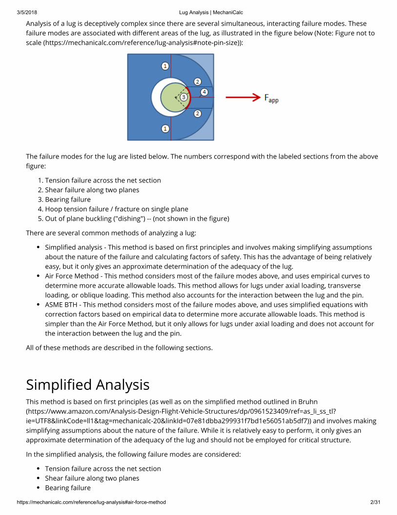
Analysis of a lug is deceptively complex since there are several simultaneous, interacting failure modes. Thesefailure modes are associated with di�erent areas of the lug, as illustrated in the �gure below (Note: Figure not toscale (https://mechanicalc.com/reference/lug-analysis#note-pin-size)):
The failure modes for the lug are listed below. The numbers correspond with the labeled sections from the above�gure:
1. Tension failure across the net section2. Shear failure along two planes3. Bearing failure4. Hoop tension failure / fracture on single plane5. Out of plane buckling ("dishing") -- (not shown in the �gure)
There are several common methods of analyzing a lug:
Simpli�ed analysis - This method is based on �rst principles and involves making simplifying assumptionsabout the nature of the failure and calculating factors of safety. This has the advantage of being relativelyeasy, but it only gives an approximate determination of the adequacy of the lug.Air Force Method - This method considers most of the failure modes above, and uses empirical curves todetermine more accurate allowable loads. This method allows for lugs under axial loading, transverseloading, or oblique loading. This method also accounts for the interaction between the lug and the pin.ASME BTH - This method considers most of the failure modes above, and uses simpli�ed equations withcorrection factors based on empirical data to determine more accurate allowable loads. This method issimpler than the Air Force Method, but it only allows for lugs under axial loading and does not account forthe interaction between the lug and the pin.
All of these methods are described in the following sections.
Simpli�ed AnalysisThis method is based on �rst principles (as well as on the simpli�ed method outlined in Bruhn(https://www.amazon.com/Analysis-Design-Flight-Vehicle-Structures/dp/0961523409/ref=as_li_ss_tl?ie=UTF8&linkCode=ll1&tag=mechanicalc-20&linkId=07e81dbba299931f7bd1e56051ab5df7)) and involves makingsimplifying assumptions about the nature of the failure. While it is relatively easy to perform, it only gives anapproximate determination of the adequacy of the lug and should not be employed for critical structure.
In the simpli�ed analysis, the following failure modes are considered:
Tension failure across the net sectionShear failure along two planesBearing failure

3/5/2018 Lug Analysis | MechaniCalc
https://mechanicalc.com/reference/lug-analysis#air-force-method 3/31
A factor of safety (https://mechanicalc.com/reference/strength-of-materials#allowable-stress-design) is calculatedfor each of the failure modes, and as long as each factor of safety is acceptable then the lug can be considered topass. The �gure below shows the lug in blue and the pin in green.
The dimensions in the �gure are:
= hole diameter = pin diameter
= edge distance (distance from center of hole to edge of lug in direction of applied load) = radius of curvature of edge of lug (greater than or equal to R) = distance from edge of hole to edge of lug = width
= thickness (not shown in �gure -- thickness is into the page) = loss in shear plane length due to curvature at end of lug = shear plane locating angle = 40°
Tension Failure Across Net SectionTension failure across the net section occurs over the cross-section highlighted in red in the �gure below:
The area of the net section is given by:
The ultimate tensile load is the load that would result in tensile failure across the net section, and is given by:
Dh
Dp
R
r
a = R − 0.5Dh
w
t
Z
ϕ
= (w − )tAt Dh

3/5/2018 Lug Analysis | MechaniCalc
https://mechanicalc.com/reference/lug-analysis#air-force-method 4/31
where is the ultimate tensile strength (https://mechanicalc.com/reference/mechanical-properties-of-materials#stress-strain-curve) of the lug material. The equation above assumes a uniform tensile stress(https://mechanicalc.com/reference/strength-of-materials#stress-and-strain) over the cross-section. In realitythere will be a stress concentration (https://mechanicalc.com/reference/strength-of-materials#stress-concentration) due to the �ow of stress around the hole.
The factor of safety is given by:
Shear Tear Out Along Two PlanesShear tear out occurs over the two shear planes highlighted in red in the �gure below:
The total shear plane area is given by:
where is the length of the shear plane and is the lug thickness. A simple and conservative approach is tocalculate the length of a single shear plane as:
where , as shown in the �gure above. If it is desired to account for a slightly longer shear plane,it is common practice to consider a 40 degree line extending from the center of the shear pin. At the point wherethat 40 degree line intersects the pin hole, extend the shear plane horizontally to the outer edge of the lug. In thiscase, is calculated as:
where is the shear plane locating angle of 40° and is the loss in shear plane length due to the curvature atthe end of the lug. This loss is calculated as:
=Ptu StuAt
Stu
F =Stu
Ptu
Fapp
= 2 tAs Lsp
Lsp t
= aLsp
a = R − 0.5Dh
Lsp
= a + (1 − cos(ϕ)) − ZLsp
Dp
2
ϕ Z
3/5/2018 Lug Analysis | MechaniCalc
https://mechanicalc.com/reference/lug-analysis#air-force-method 5/31
Note that if the lug end is �at then is in�nity and is zero.
The ultimate shear load is the load that would result in shear tear out along the two planes, and is given by:
where is the ultimate shear strength of the lug material.
The factor of safety is given by:
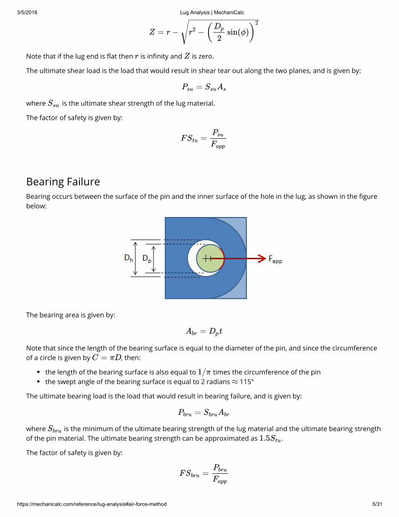
Bearing FailureBearing occurs between the surface of the pin and the inner surface of the hole in the lug, as shown in the �gurebelow:
The bearing area is given by:
Note that since the length of the bearing surface is equal to the diameter of the pin, and since the circumferenceof a circle is given by , then:
the length of the bearing surface is also equal to times the circumference of the pinthe swept angle of the bearing surface is equal to 2 radians 115°
The ultimate bearing load is the load that would result in bearing failure, and is given by:
where is the minimum of the ultimate bearing strength of the lug material and the ultimate bearing strengthof the pin material. The ultimate bearing strength can be approximated as .
The factor of safety is given by:
Z = r − −r2 ( sin(ϕ))Dp
2
2− −−−−−−−−−−−−−−√r Z
=Psu SsuAs
Ssu
F =Stu
Psu
Fapp
= tAbr Dp
C = πD
1/π≈
=Pbru SbruAbr
Sbru
1.5Stu
F =Sbru
Pbru
Fapp

3/5/2018 Lug Analysis | MechaniCalc
https://mechanicalc.com/reference/lug-analysis#air-force-method 6/31
If a bushing is pressed into the lug, then bearing needs to be calculated for both sets of contact:
Pin on bushingBushing on lug
Air Force Method
This section discusses axial loading, transverse loading, and oblique loading separately. These sections disregardthe e�ect of the pin on the lug strength. A discussion of the pin and lug interaction is given at the end.
Axial LoadingFor axially loaded lugs, the Air Force method evaluates the lug for bearing failure, shear-out failure, hoop tensionfailure, and failure across the net section. Three of the failure modes are actually combined into a single failuremode -- the "bearing strength" accounts for bearing, shear-out, and hoop tension. This is consistent with Bruhn(https://www.amazon.com/Analysis-Design-Flight-Vehicle-Structures/dp/0961523409/ref=as_li_ss_tl?ie=UTF8&linkCode=ll1&tag=mechanicalc-20&linkId=07e81dbba299931f7bd1e56051ab5df7) and Melcon & Hoblit.
The dimensions of interest for an axially loaded lug are shown in the �gure below:
Mailing ListSubscribe to receive occasional updates on the latest improvements:
Email Address
Subscribe
The Air Force Method is widely used in industry and is documented in the Stress Analysis Manual of the Air ForceFlight Dynamics Laboratory (FDL). This method follows closely with the methods presented in Melcon & Hoblitand Bruhn (https://www.amazon.com/Analysis-Design-Flight-Vehicle-Structures/dp/0961523409/ref=as_li_ss_tl?ie=UTF8&linkCode=ll1&tag=mechanicalc-20&linkId=07e81dbba299931f7bd1e56051ab5df7), and it relies heavilyon curves generated by empirical data. Although this method is somewhat more complex than other lug analysismethods, it is incredibly useful because it allows for lugs under axial loading, transverse loading, or obliqueloading, and because it accounts for the interaction between the lug and the pin.
Lug Calculator (https://mechanicalc.com/calculators/lifting-lug-analysis/)Check out our lug calculator (https://mechanicalc.com/calculators/lifting-lug-analysis/) based on the Air ForceMethod described here.
3/5/2018 Lug Analysis | MechaniCalc
https://mechanicalc.com/reference/lug-analysis#air-force-method 7/31
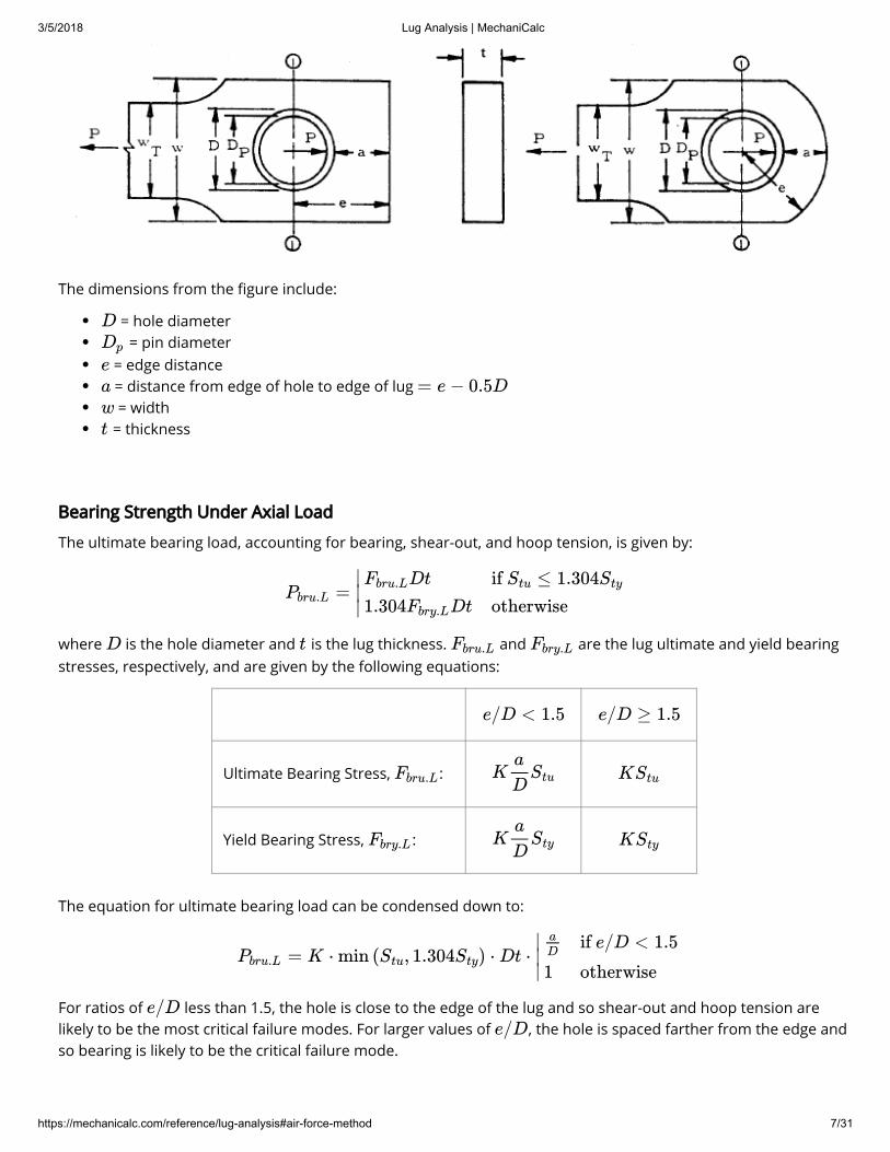
The dimensions from the �gure include:
Bearing Strength Under Axial Load
The ultimate bearing load, accounting for bearing, shear-out, and hoop tension, is given by:
where is the hole diameter and is the lug thickness. and are the lug ultimate and yield bearingstresses, respectively, and are given by the following equations:
Ultimate Bearing Stress, :
Yield Bearing Stress, :
The equation for ultimate bearing load can be condensed down to:
For ratios of less than 1.5, the hole is close to the edge of the lug and so shear-out and hoop tension arelikely to be the most critical failure modes. For larger values of , the hole is spaced farther from the edge andso bearing is likely to be the critical failure mode.
= hole diameter = pin diameter
= edge distance = distance from edge of hole to edge of lug = width
= thickness
D
Dp
e
a = e − 0.5Dw
t
=Pbru.L
∣
∣∣
DtFbru.L
1.304 DtFbry.L
if ≤ 1.304Stu Sty
otherwise
D t Fbru.L Fbry.L
e/D < 1.5 e/D ≥ 1.5
Fbru.L Ka
DStu KStu
Fbry.L Ka
DSty KSty
= K ⋅ min ( , 1.304 ) ⋅ Dt ⋅Pbru.L Stu Sty
∣
∣∣
aD
1
if e/D < 1.5
otherwise
e/De/D

3/5/2018 Lug Analysis | MechaniCalc
https://mechanicalc.com/reference/lug-analysis#air-force-method 8/31
The factor in the equations above is the allowable axial load coe�cient which accounts for the interactione�ects between the di�erent failure modes (bearing, shear-out, and hoop tension). The value of is read o� ofone of the following two plots. The �rst plot is used for , which is the most common case. If then the lug is thin, and in that case the value of is read o� of the second plot below.
K
K
D/t ≤ 5 D/t > 5K (Note 2)
(https://mechanicalc.com/reference/lug-analysis#note-axial-load-coe�cient-plot)

3/5/2018 Lug Analysis | MechaniCalc
https://mechanicalc.com/reference/lug-analysis#air-force-method 9/31
Bushing Bearing Strength Under Axial Load
If there is a bushing in the lug, then the bearing strength for the bushing must be calculated. The bushingultimate load is given by:
where is the pin diameter, is the bushing thickness (assumed to be equal to the lug thickness), and isthe compressive yield strength of the bushing material. The Air Force manual assumes the compressive ultimatestrength of the bushing material, , to be equal to .
If there is no bushing in the lug, then the calculation should still be performed assuming that the lug material isthe bushing material.
Net Section Strength Under Axial Load
The net-section ultimate load accounts for tension failure across the net section and is calculated by:
= 1.304 tPu.B Scy.BDp
Dp t Scy.B
Scu.B 1.304Scy.B
=Pnu.L
∣
∣∣
(w − D)tFnu.L
1.304 (w − D)tFny.L
if ≤ 1.304Stu Sty
otherwise
3/5/2018 Lug Analysis | MechaniCalc
https://mechanicalc.com/reference/lug-analysis#air-force-method 10/31
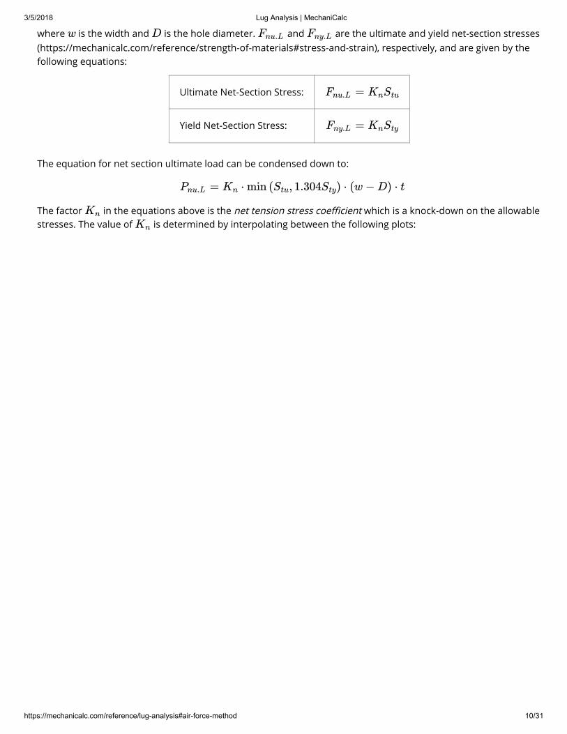
where is the width and is the hole diameter. and are the ultimate and yield net-section stresses(https://mechanicalc.com/reference/strength-of-materials#stress-and-strain), respectively, and are given by thefollowing equations:
Ultimate Net-Section Stress:
Yield Net-Section Stress:
The equation for net section ultimate load can be condensed down to:
The factor in the equations above is the net tension stress coe�cient which is a knock-down on the allowablestresses. The value of is determined by interpolating between the following plots:
w D Fnu.L Fny.L
=Fnu.L KnStu
=Fny.L KnSty
= ⋅ min ( , 1.304 ) ⋅ (w − D) ⋅ tPnu.L Kn Stu Sty
Kn
Kn

3/5/2018 Lug Analysis | MechaniCalc
https://mechanicalc.com/reference/lug-analysis#air-force-method 11/31
Design Strength Under Axial Load
The design ultimate load for an axially loaded lug is the minimum of the ultimate bearing load, the ultimatebushing load, and the ultimate net-section load:

3/5/2018 Lug Analysis | MechaniCalc
https://mechanicalc.com/reference/lug-analysis#air-force-method 12/31
Transverse LoadingThe analysis for a transversely loaded lug is similar to that for an axially loaded lug. However, the failure mode fortransverse loading is more complicated than for axial loading, and di�erent dimensions are critical fordetermining lug strength. The dimensions of interest for a transversely loaded lug are shown in the �gure below:
where , , , and are failure planes of interest. If the lug is symmetric, then the values for thesedimensions can be easily obtained from the dimensions for an axially loaded lug:
It should be noted that is de�ned as the smallest dimension on any radial section around the hole, but it willtypically be equal to . From the above dimensions, the e�ective edge distance is calculated:
The equation above is simply a "reciprocal average" that gives more weighting to dimension since that sectiontakes most of the load.
Lug Strength Under Transverse Load
The ultimate transverse load is given by:
where is the hole diameter and is the lug thickness. and are the lug ultimate and yield bearingstresses, respectively, and are given by the following equations:
Ultimate Bearing Stress:
= min ( , , )Pu.L.B Pbru.L Pu.B Pnu.L
h1 h2 h3 h4
= 0.5(w − D)h2
= = + 0.5D(1 − cos )h1 h4 h2 45∘
= ah3
h3
a
=hav6
3/ + 1/ + 1/ + 1/h1 h2 h3 h4
h1(Note 3) (https://mechanicalc.com/reference/lug-analysis#note-reciprocal-average)
=Ptru.L
∣
∣∣
DtFbru.L
1.304 DtFbry.L
if ≤ 1.304Stu Sty
otherwise
D t Fbru.L Fbry.L
=Fbru.L KtruStu
3/5/2018 Lug Analysis | MechaniCalc
https://mechanicalc.com/reference/lug-analysis#air-force-method 13/31
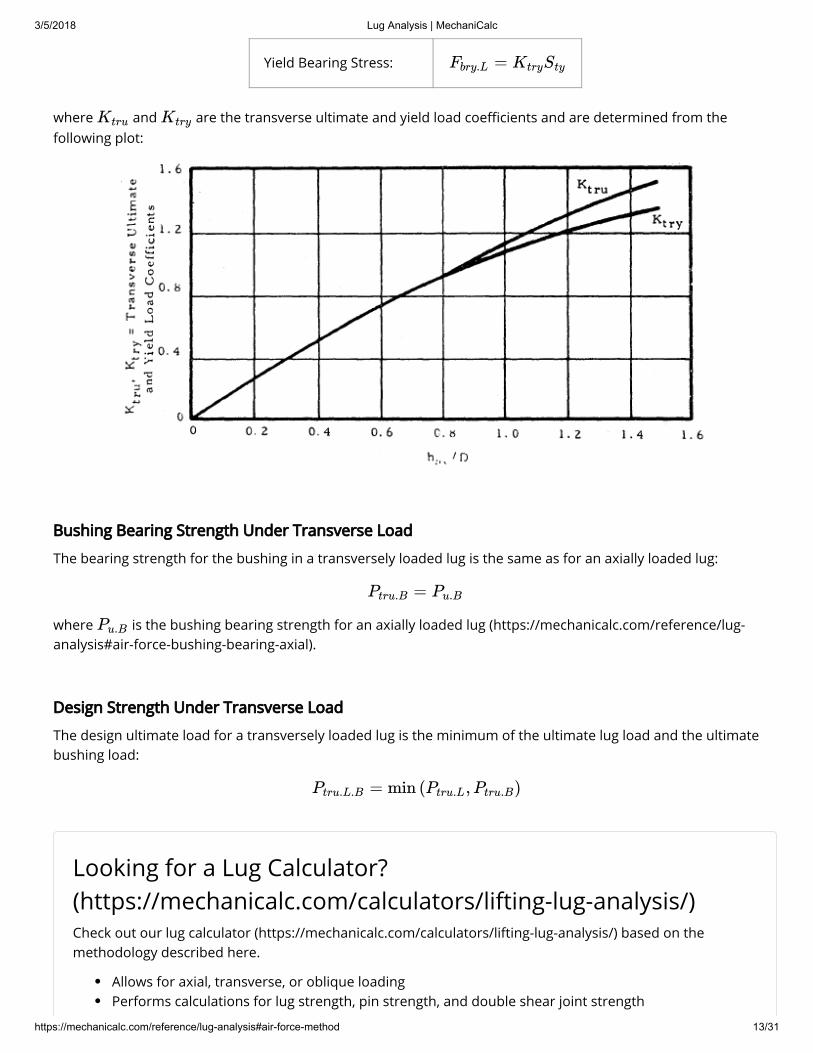
Yield Bearing Stress:
where and are the transverse ultimate and yield load coe�cients and are determined from thefollowing plot:
Bushing Bearing Strength Under Transverse Load
The bearing strength for the bushing in a transversely loaded lug is the same as for an axially loaded lug:
where is the bushing bearing strength for an axially loaded lug (https://mechanicalc.com/reference/lug-analysis#air-force-bushing-bearing-axial).
Design Strength Under Transverse Load
The design ultimate load for a transversely loaded lug is the minimum of the ultimate lug load and the ultimatebushing load:
=Fbry.L KtrySty
Ktru Ktry
=Ptru.B Pu.B
Pu.B
= min ( , )Ptru.L.B Ptru.L Ptru.B
Looking for a Lug Calculator?(https://mechanicalc.com/calculators/lifting-lug-analysis/)Check out our lug calculator (https://mechanicalc.com/calculators/lifting-lug-analysis/) based on themethodology described here.
Allows for axial, transverse, or oblique loadingPerforms calculations for lug strength, pin strength, and double shear joint strength
3/5/2018 Lug Analysis | MechaniCalc
https://mechanicalc.com/reference/lug-analysis#air-force-method 14/31
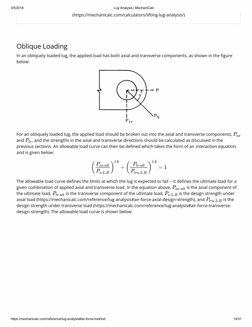
Oblique LoadingIn an obliquely loaded lug, the applied load has both axial and transverse components, as shown in the �gurebelow:
For an obliquely loaded lug, the applied load should be broken out into the axial and transverse components, and , and the strengths in the axial and transverse directions should be calculated as discussed in theprevious sections. An allowable load curve can then be de�ned which takes the form of an interaction equation,and is given below:
The allowable load curve de�nes the limits at which the lug is expected to fail -- it de�nes the ultimate load for agiven combination of applied axial and transverse load. In the equation above, is the axial component ofthe ultimate load, is the transverse component of the ultimate load, is the design strength underaxial load (https://mechanicalc.com/reference/lug-analysis#air-force-axial-design-strength), and is thedesign strength under transverse load (https://mechanicalc.com/reference/lug-analysis#air-force-transverse-design-strength). The allowable load curve is shown below:
(https://mechanicalc.com/calculators/lifting-lug-analysis/)
Pax
Ptr
+ = 1( )Pax.ult
Pu.L.B
1.6 ( )Ptr.ult
Ptru.L.B
1.6
Pax.ult
Ptr.ult Pu.L.B
Ptru.L.B

3/5/2018 Lug Analysis | MechaniCalc
https://mechanicalc.com/reference/lug-analysis#air-force-method 15/31
In the �gure above, the values along the y-axis are the ratios of the transverse applied load to the transversestrength, and the values along the x-axis are the ratios of the axial applied load to the axial strength.
Axial Load Ratio Transverse Load Ratio
The point for the applied load with coordinates of should be plotted. Any point that falls within theallowable load curve has a factor of safety (https://mechanicalc.com/reference/strength-of-materials#allowable-stress-design) ≥ 1 with respect to the ultimate load. Note that if the applied load is completely axial, then thevalue for is 0 and the point lies along the x-axis, and so the ultimate load is simply the axial designstrength. Likewise for a completely transverse applied load; in this case, the point lies along the y-axis and so theultimate load is the transverse design strength.
For an applied load with both axial and transverse components, the ultimate load is calculated by drawing a linefrom the origin, through the point , and then through the allowable load curve. This is the load line,and it has a slope of:
The ultimate load ratios are given by the intersection of the load line with the allowable load curve. Theseultimate ratios can then be used to calculate the ultimate load values in the axial and transverse directions.
=Rax
Pax
Pu.L.B=Rtr
Ptr
Ptru.L.B
( , )Rax Rtr
Rtr ( , )Rax Rtr
( , )Rax Rtr
m = =Rtr
Rax
Ptr
Ptru.L.B
Pu.L.B
Pax
3/5/2018 Lug Analysis | MechaniCalc
https://mechanicalc.com/reference/lug-analysis#air-force-method 16/31
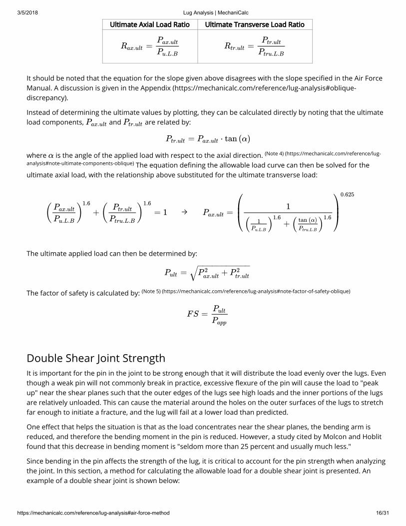
Ultimate Axial Load Ratio Ultimate Transverse Load Ratio
It should be noted that the equation for the slope given above disagrees with the slope speci�ed in the Air ForceManual. A discussion is given in the Appendix (https://mechanicalc.com/reference/lug-analysis#oblique-discrepancy).
Instead of determining the ultimate values by plotting, they can be calculated directly by noting that the ultimateload components, and are related by:
where is the angle of the applied load with respect to the axial direction. The equation de�ning the allowable load curve can then be solved for the
ultimate axial load, with the relationship above substituted for the ultimate transverse load:
→
The ultimate applied load can then be determined by:
The factor of safety is calculated by:
Double Shear Joint StrengthIt is important for the pin in the joint to be strong enough that it will distribute the load evenly over the lugs. Eventhough a weak pin will not commonly break in practice, excessive �exure of the pin will cause the load to "peakup" near the shear planes such that the outer edges of the lugs see high loads and the inner portions of the lugsare relatively unloaded. This can cause the material around the holes on the outer surfaces of the lugs to stretchfar enough to initiate a fracture, and the lug will fail at a lower load than predicted.
One e�ect that helps the situation is that as the load concentrates near the shear planes, the bending arm isreduced, and therefore the bending moment in the pin is reduced. However, a study cited by Molcon and Hoblitfound that this decrease in bending moment is "seldom more than 25 percent and usually much less."
Since bending in the pin a�ects the strength of the lug, it is critical to account for the pin strength when analyzingthe joint. In this section, a method for calculating the allowable load for a double shear joint is presented. Anexample of a double shear joint is shown below:
=Rax.ultPax.ult
Pu.L.B=Rtr.ult
Ptr.ult
Ptru.L.B
Pax.ult Ptr.ult
= ⋅ tan (α)Ptr.ult Pax.ult
α (Note 4) (https://mechanicalc.com/reference/lug-
analysis#note-ultimate-components-oblique)
+ = 1( )Pax.ult
Pu.L.B
1.6 ( )Ptr.ult
Ptru.L.B
1.6
=Pax.ult
⎛⎝⎜⎜
1
+( )1Pu.L.B
1.6 ( )tan (α)
Ptru.L.B
1.6
⎞⎠⎟⎟
0.625
=Pult +P 2ax.ult P 2
tr.ult
− −−−−−−−−−−√(Note 5) (https://mechanicalc.com/reference/lug-analysis#note-factor-of-safety-oblique)
FS =Pult
Papp

3/5/2018 Lug Analysis | MechaniCalc
https://mechanicalc.com/reference/lug-analysis#air-force-method 17/31
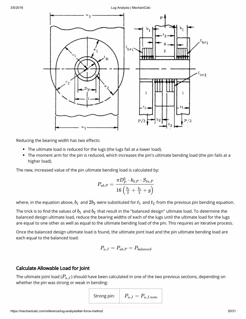
In a double shear joint, there are two outer (female) lugs, a single inner (male) lug, and a pin.
The overall process of determining the allowable load is illustrated in the diagram below:
3/5/2018 Lug Analysis | MechaniCalc
https://mechanicalc.com/reference/lug-analysis#air-force-method 18/31
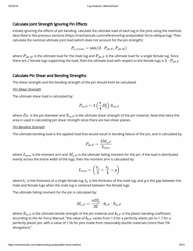
Calculate Joint Strength Ignoring Pin E�ects
Initially ignoring the e�ects of pin bending, calculate the ultimate load of each lug in the joint using the methodsdescribed in the previous sections (https://mechanicalc.com/reference/lug-analysis#air-force-oblique-lug). Thencalculate the nominal ultimate joint load (which does not account for the pin strength):
where is the ultimate load for the male lug and is the ultimate load for a single female lug. Sincethere are 2 female lugs supporting the load, then the ultimate load with respect to the female lugs is .
Calculate Pin Shear and Bending Strengths
The shear strength and the bending strength of the pin should both be calculated.
Pin Shear Strength
The ultimate shear load is calculated by:
where is the pin diameter and is the ultimate shear strength of the pin material. Note that twice thearea is used in calculating pin shear strength since there are two shear planes.
Pin Bending Strength
The ultimate bending load is the applied load that would result in bending failure of the pin, and is calculated by:
where is the moment arm and is the ultimate failing moment for the pin. If the load is distributedevenly across the entire width of the lugs, then the moment arm is calculated by:
where is the thickness of a single female lug, is the thickness of the male lug, and is the gap between themale and female lugs when the male lug is centered between the female lugs.
The ultimate failing moment for the pin is calculated by:
where is the ultimate tensile strength of the pin material and is the plastic bending coe�cient.According to the Air Force Manual, "the value of varies from 1.0 for a perfectly elastic pin to 1.7 for aperfectly plastic pin, with a value of 1.56 for pins made from reasonably ductile materials (more than 5%elongation)."
= min (2 ⋅ , )Pu.J.nom Pult.F Pult.M
Pult.M Pult.F
2 ⋅ Pult.F
= 2( )Pus.Pπ
4D2
p Ssu.P
DP Ssu.P
=Pub.P2Mu.P
Larm
Larm Mu.P
= ( + + g)Larm
t1
2
t2
4
t1 t2 g
= ⋅ ⋅Mu.P
πD3P
32kb.P Stu.P
Stu.P kb.Pkb.P

3/5/2018 Lug Analysis | MechaniCalc
https://mechanicalc.com/reference/lug-analysis#air-force-method 19/31
Pin Strong or Weak in Bending?
Once the pin strengths are calculated, determine whether the pin is strong or weak in bending. If the pin ultimatebending load is greater than either the pin ultimate shear load or the nominal ultimate joint load
, then the pin is relatively strong and is not critical in bending. Otherwise, the pin is weak and is criticalin bending.
or ?Yes → Strong PinNo → Weak Pin
Strong Pin
If the pin is strong, the joint strength will be limited by either the pin shear strength or by the nominal jointstrength. In the case of a strong pin, the pin ultimate bending load is calculated assuming that the loaddistributes evenly over the full width of the lugs:
The equation above is the same as the equation presented earlier for the ultimate pin bending load, but with theterms combined into a single equation.
For a strong pin, the pin bending does not a�ect the joint strength and the ultimate joint load is equal to thenominal ultimate joint load:
Weak Pin
If the pin is weak in bending, then the load will not be distributed evenly over the lug widths. Instead, the load willconcentrate toward the shear planes, and the inner portions of the lugs will be relatively unloaded. Because ofthis, the lugs will fail at a lower load than predicted.
To account for the low pin bending strength, a "balanced design" ultimate load is calculated. The goal is todetermine the actual bearing widths over which the lugs support the load. Instead of the load being supportedover the full lug thicknesses, and , the load will instead be distributed over some smaller widths, and ,as shown in the �gure below. It is assumed that the load is uniformly distributed over these widths.
( )Pub.P ( )Pus.P
( )Pu.J.nom
≥Pub.P Pu.J.nom ≥Pub.P Pus.P
=Pub.P
π ⋅ ⋅D3P
kb.P Stu.P
16( + + g)t12
t24
=Pu.J Pu.J.nom
t1 t2 b1 b2
3/5/2018 Lug Analysis | MechaniCalc
https://mechanicalc.com/reference/lug-analysis#air-force-method 20/31
Reducing the bearing width has two e�ects:
The ultimate load is reduced for the lugs (the lugs fail at a lower load).The moment arm for the pin is reduced, which increases the pin's ultimate bending load (the pin fails at ahigher load).
The new, increased value of the pin ultimate bending load is calculated by:
where, in the equation above, and were substituted for and from the previous pin bending equation.
The trick is to �nd the values of and that result in the "balanced design" ultimate load. To determine thebalanced design ultimate load, reduce the bearing widths of each of the lugs until the ultimate load for the lugsare equal to one other as well as equal to the ultimate bending load of the pin. This requires an iterative process.
Once the balanced design ultimate load is found, the ultimate joint load and the pin ultimate bending load areeach equal to the balanced load:
Calculate Allowable Load for Joint
The ultimate joint load ( ) should have been calculated in one of the two previous sections, depending onwhether the pin was strong or weak in bending:
Strong pin:
=Pub.P
π ⋅ ⋅D3P
kb.P Stu.P
16( + + g)b1
2b2
2
b1 2b2 t1 t2
b1 b2
= =Pu.J Pub.P Pbalanced
Pu.J
=Pu.J Pu.J.nom
3/5/2018 Lug Analysis | MechaniCalc
https://mechanicalc.com/reference/lug-analysis#air-force-method 21/31
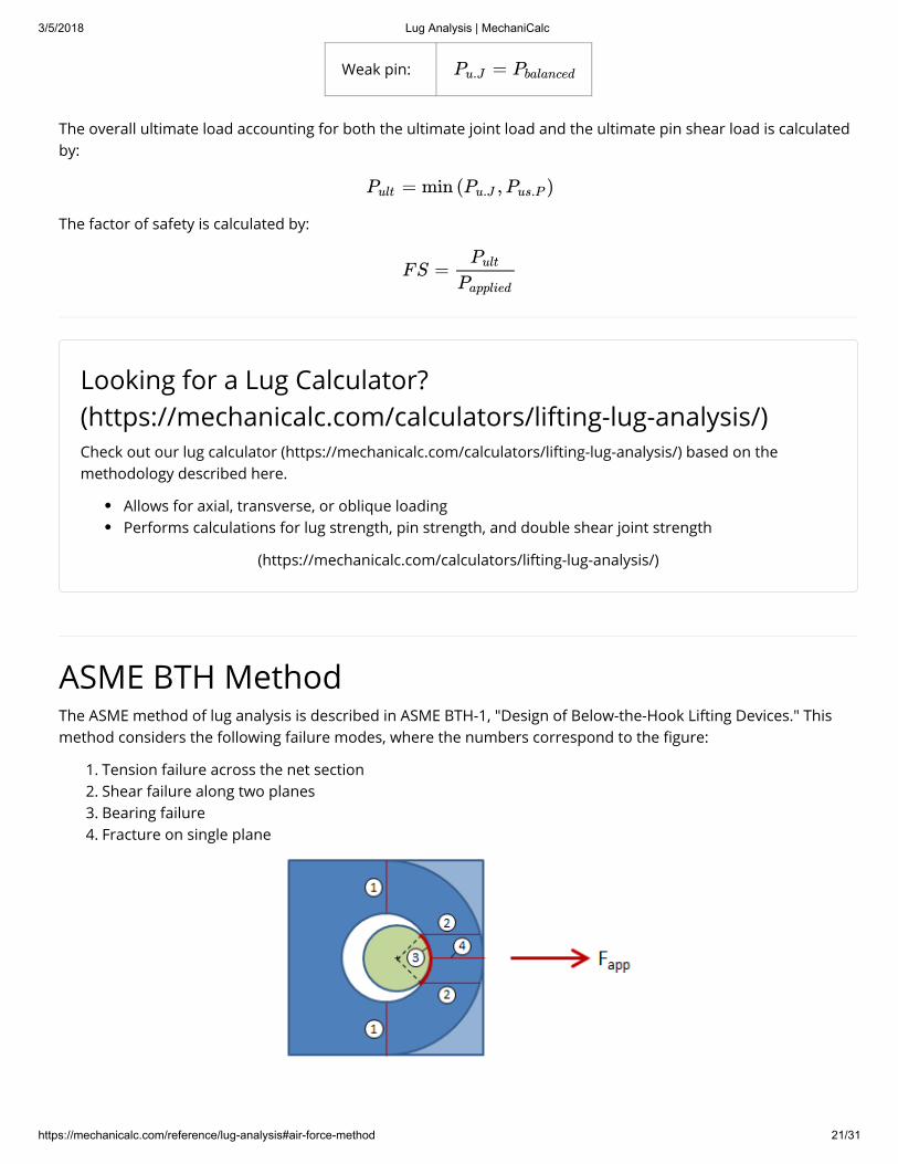
Weak pin:
The overall ultimate load accounting for both the ultimate joint load and the ultimate pin shear load is calculatedby:
The factor of safety is calculated by:
ASME BTH MethodThe ASME method of lug analysis is described in ASME BTH-1, "Design of Below-the-Hook Lifting Devices." Thismethod considers the following failure modes, where the numbers correspond to the �gure:
1. Tension failure across the net section2. Shear failure along two planes3. Bearing failure4. Fracture on single plane
=Pu.J Pbalanced
= min ( , )Pult Pu.J Pus.P
FS =Pult
Papplied
Looking for a Lug Calculator?(https://mechanicalc.com/calculators/lifting-lug-analysis/)Check out our lug calculator (https://mechanicalc.com/calculators/lifting-lug-analysis/) based on themethodology described here.
Allows for axial, transverse, or oblique loadingPerforms calculations for lug strength, pin strength, and double shear joint strength
(https://mechanicalc.com/calculators/lifting-lug-analysis/)

3/5/2018 Lug Analysis | MechaniCalc
https://mechanicalc.com/reference/lug-analysis#air-force-method 22/31
While the factor of safety (https://mechanicalc.com/reference/strength-of-materials#allowable-stress-design) ondishing (out-of-plane buckling) is not explicitly calculated, the e�ective width calculation accounts for the lugthickness in an attempt to protect against dishing failure.
The dimensions of interest for the lug analysis are shown in the �gure below:
The dimensions from the �gure include:
= hole diameter = pin diameter
= net width (distance between the edge of the hole and the edge of the lug in the transverse direction) = edge distance (distance from the center of the hole to the edge of the lug in the direction of applied
load) = radius of curvature of edge of lug (greater than or equal to ) = distance from the edge of the hole to the edge of the lug = thickness (not shown in �gure -- thickness is into the page) = loss in shear plane length due to curvature at the end of the lug = shear plane locating angle
Correction FactorsThe analysis in ASME BTH is very similar to the simpli�ed analysis (https://mechanicalc.com/reference/lug-analysis#simpli�ed-analysis), with the exception of several correction factors that are calculated based on testresults. These correction factors are discussed below.
Strength Reduction Factor
The lug strength is reduced as the �t between the pin and the hole is loosened. The lug strength is not mucha�ected as long as the pin and hole are a relatively tight �t. ASME de�nes a strength reduction factor that can beused to account for the pin-to-hole clearance as:
Dh
Dp
beR
r R
a = R − 0.5Dh
t
Z
ϕ
=Cr
∣
∣
∣∣
1
1 − 0.275 1 −D2
p
D2h
− −−−−−√if / > 0.9Dp Dh
otherwise

3/5/2018 Lug Analysis | MechaniCalc
https://mechanicalc.com/reference/lug-analysis#air-force-method 23/31
where is the pin diameter and is the hole diameter.
Shear Plane Locating Angle
A shear plane locating angle, , is used to locate the two planes along which shear tear out occurs, as shown inthe �gure:
A larger value of results in a larger shear plane area. Other methodologies commonly take as a constantvalue (typically 40°), but ASME relates it to the ratio of the pin diameter to the hole diameter such that a loose-�tting pin has a smaller shear plane area than a tight-�tting pin:
E�ective Width
The term is referred to as the net width and is the distance between the edge of the hole and the edge of thelug in the transverse direction, as shown in the �gure:
In the tension calculations, an e�ective width is calculated and is the smallest of the following:
• The e�ective width should not be larger than the actual net width.
Dp Dh
ϕ
ϕ ϕ
ϕ = 55∘ Dp
Dh
be
=beff.1 be

3/5/2018 Lug Analysis | MechaniCalc
https://mechanicalc.com/reference/lug-analysis#air-force-method 24/31
• This limit is intended to protect against dishing failure (once the lugthickness drops below 1/4 of the net width , the e�ective width isdriven down). This limit can be ignored if the lug is sti�ened orconstrained against buckling.
• This equation is empirical, �tted to test results.
The e�ective width is calculated as:
Design Factor & Service ClassA design factor (i.e. required factor of safety), , is used in the strength calculations. The value for can befound from the table below:
DesignFactor
Condition
= 2.00Design Category A lifters (predictable loads, accurately de�ned or non-severeenvironmental conditions, no more than 20,000 load cycles)
= 3.00Design Category B lifters (unpredictable loads, uncertain or severe environmentalconditions)
A service class is used to account for fatigue life and is de�ned based on the table below:
Service Class Load Cycles0 0 - 20,0001 20,001 - 100,0002 100,001 - 500,0003 500,001 - 2,000,0004 Over 2,000,000
Lug Strength CalculationsThese strength calculations are only applicable for axially applied loads, as indicated by the applied force arrow inthe �gure below:
= 4tbeff.2
be
= 0.6beff.3 beStu
Sty
Dh
be
−−−√
= min ( , , )beff beff.1 beff.2 beff.3
Nd Nd
Nd
Nd

3/5/2018 Lug Analysis | MechaniCalc
https://mechanicalc.com/reference/lug-analysis#air-force-method 25/31
To determine whether the lug has su�cient strength, calculate a factor of safety(https://mechanicalc.com/reference/strength-of-materials#allowable-stress-design) for each of the failure modesdescribed below. As long as the applied force is within the allowable load, and as long as each factor of safety isacceptable, then the lug can be considered to pass.
Tensile Strength
The ultimate tensile load is the load that would result in tensile failure across the net section, and is given by:
where is the strength reduction factor (https://mechanicalc.com/reference/lug-analysis#asme-strength-reduction-factor) and is the ultimate tensile strength of the lug. is the area of the net section and iscalculated by:
where is the e�ective width (https://mechanicalc.com/reference/lug-analysis#asme-e�ective-width) and isthe lug thickness.
The allowable tensile load is based on the design factor, , and is given by:
Note that the allowable tensile load is based on the design factor multiplied by 1.20. ASME requires the designfactor for some of the strength calculations to be higher than the nominal value. The factor of safety is given by:
To meet ASME BTH, the factor of safety must be at least , but the required factor of safety may be largerdepending on customer requirements or engineering judgement.
Single Plane Fracture Strength
= ⋅ ⋅Pt.u Cr Stu At
Cr
Stu At
= 2 ⋅ t ⋅At beff
beff t
Nd
=Pt
Pt.u
1.20Nd
F =St
Pt.u
Fapp
1.20Nd
3/5/2018 Lug Analysis | MechaniCalc
https://mechanicalc.com/reference/lug-analysis#air-force-method 26/31
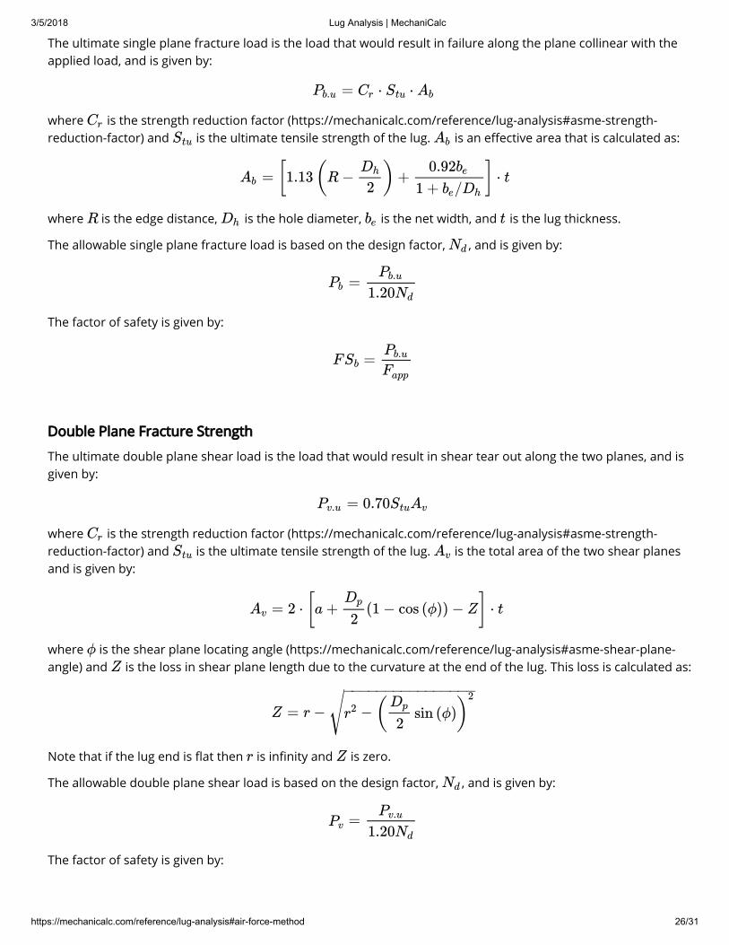
The ultimate single plane fracture load is the load that would result in failure along the plane collinear with theapplied load, and is given by:
where is the strength reduction factor (https://mechanicalc.com/reference/lug-analysis#asme-strength-reduction-factor) and is the ultimate tensile strength of the lug. is an e�ective area that is calculated as:
where is the edge distance, is the hole diameter, is the net width, and is the lug thickness.
The allowable single plane fracture load is based on the design factor, , and is given by:
The factor of safety is given by:
Double Plane Fracture Strength
The ultimate double plane shear load is the load that would result in shear tear out along the two planes, and isgiven by:
where is the strength reduction factor (https://mechanicalc.com/reference/lug-analysis#asme-strength-reduction-factor) and is the ultimate tensile strength of the lug. is the total area of the two shear planesand is given by:
where is the shear plane locating angle (https://mechanicalc.com/reference/lug-analysis#asme-shear-plane-angle) and is the loss in shear plane length due to the curvature at the end of the lug. This loss is calculated as:
Note that if the lug end is �at then is in�nity and is zero.
The allowable double plane shear load is based on the design factor, , and is given by:
The factor of safety is given by:
= ⋅ ⋅Pb.u Cr Stu Ab
Cr
Stu Ab
= [1.13(R − ) + ] ⋅ tAb
Dh
2
0.92be
1 + /be Dh
R Dh be t
Nd
=Pb
Pb.u
1.20Nd
F =SbPb.u
Fapp
= 0.70Pv.u StuAv
Cr
Stu Av
= 2 ⋅ [a + (1 − cos (ϕ)) − Z] ⋅ tAv
Dp
2
ϕ
Z
Z = r − −r2 ( sin (ϕ))Dp
2
2− −−−−−−−−−−−−−−−√r Z
Nd
=Pv
Pv.u
1.20Nd
3/5/2018 Lug Analysis | MechaniCalc
https://mechanicalc.com/reference/lug-analysis#air-force-method 27/31
Bearing Strength
The ultimate bearing load is the load that would result in bearing failure on either the lug or the pin. This ultimateload is dependent on the number of load cycles that the connection will be subjected to, and is given by:
where is the minimum yield strength between the lug and the pin (i.e. ). is the pin bearing area and is calculated by:
The allowable bearing load is based on the design factor, , and is given by:
The factor of safety is given by:
Appendix
Discrepancy With Air Force Manual - Oblique Loading
F =Sv
Pv.u
Fapp
=Pp.u
∣
∣∣1.25 ⋅ ⋅Sty.min Ap
0.63 ⋅ ⋅Sty.min Ap
for Service Class 0
for Service Class 1 or higher
Sty.min = min ( , )Sty.min Sty.lug Sty.pin
Ap
= tAp Dp
Nd
=Pp
Pp.u
Nd
F =Sp
Pp.u
Fapp
Need Structural Calculators?(https://mechanicalc.com/calculators/)We have a number of structural calculators (https://mechanicalc.com/calculators/) to choose from. Hereare just a few:
Beam Calculator (https://mechanicalc.com/calculators/beam-analysis/)Bolted Joint Calculator (https://mechanicalc.com/calculators/bolted-joint-analysis/)Bolt Pattern Force Distribution (https://mechanicalc.com/calculators/bolt-pattern-force-distribution/)Lug Calculator (https://mechanicalc.com/calculators/lifting-lug-analysis/)Column Buckling Calculator (https://mechanicalc.com/calculators/column-buckling/)
(https://mechanicalc.com/calculators/)
3/5/2018 Lug Analysis | MechaniCalc
https://mechanicalc.com/reference/lug-analysis#air-force-method 28/31
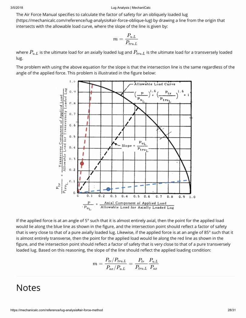
The Air Force Manual speci�es to calculate the factor of safety for an obliquely loaded lug(https://mechanicalc.com/reference/lug-analysis#air-force-oblique-lug) by drawing a line from the origin thatintersects with the allowable load curve, where the slope of the line is given by:
where is the ultimate load for an axially loaded lug and is the ultimate load for a transversely loadedlug.
The problem with using the above equation for the slope is that the intersection line is the same regardless of theangle of the applied force. This problem is illustrated in the �gure below:
If the applied force is at an angle of 5° such that it is almost entirely axial, then the point for the applied loadwould lie along the blue line as shown in the �gure, and the intersection point should re�ect a factor of safetythat is very close to that of a pure axially loaded lug. Likewise, if the applied force is at an angle of 85° such that itis almost entirely transverse, then the point for the applied load would lie along the red line as shown in the�gure, and the intersection point should re�ect a factor of safety that is very close to that of a pure transverselyloaded lug. Based on this reasoning, the slope of the line should re�ect the applied loading condition:
Notes
m =Pu.L
Ptru.L
Pu.L Ptru.L
m = =/Ptr Ptru.L
/Pax Pu.L
Ptr
Ptru.L
Pu.L
Pax

3/5/2018 Lug Analysis | MechaniCalc
https://mechanicalc.com/reference/lug-analysis#air-force-method 29/31
Note 1: Lug & Clevis Relative Sizing
It should be noted that the �gure showing the lug with the clevis pin (https://mechanicalc.com/reference/lug-analysis#plot-lug-failure-modes) does not accurately depict the relative sizing. The clevis pin should be a relativelytight �t in the lug. Per ASME, the pin diameter should be at least 90% of the lug hole diameter to avoid areduction in the joint strength (https://mechanicalc.com/reference/lug-analysis#asme-strength-reduction-factor).
Note 2: Axial Load Coe�cient Plot
The variable names used in the Axial Load Coe�cient plot (https://mechanicalc.com/reference/lug-analysis#plot-axial-load-coe�-thin) from the Air Force Manual are inconsistent with the rest of the variable names throughoutthe manual. This plot originated in Melcon & Hoblit, and the variable names from the plot were not updated tomatch. The Air Force Manual uses the variable for edge distance (center of hole to edge of lug) and for thedistance between the edge of the hole to the edge of the lug. However, the plot uses for the edge distance(center of hole to edge of lug).
Note 3: Reciprocal Average for Transverse Lug Dimensions
The e�ective edge distance for a transversely loaded lug (https://mechanicalc.com/reference/lug-analysis#air-force-transverse-lug) is calculated using a reciprocal average. The e�ect of the reciprocal average is that the resultis dominated by the smaller terms such that a disproportionately large value will not drive up the average much,but a disproportionately small value will drop the average signi�cantly (i.e. a weak link -- this is the same e�ectseen by placing springs in series). The use of this equation for calculating the e�ective edge distance for atransversely loaded lug originated with Melcon and Hoblit. They stated that the reason for the coe�cient 3 on the
term was to reduce scatter on their test data, but that it made sense because in a transversely loaded lug the section will be taking most of the load.
Note 4: Relationship Between Ultimate Load Components for Oblique Loading
To calculate the ultimate load components for an obliquely loaded lug (https://mechanicalc.com/reference/lug-analysis#air-force-oblique-lug), it is necessary to determine a relationship between the ultimate components. It isknown that the actual load ratios are proportional to the ultimate load ratios since these ratios lie along the sameload line:
Express the ratios in terms of the load components and simplify:
The load components are related by the angle of the applied load:
e a
a
h1
h1
=Rtr
Rax
Rtr.ult
Rax.ult
⋅ = ⋅Ptr
Ptru.L.B
Pu.L.B
Pax
Ptr.ult
Ptru.L.B
Pu.L.B
Pax.ult
=Ptr
Pax
Ptr.ult
Pax.ult
tan (α) = =Ptr
Pax
Ptr.ult
Pax.ult

3/5/2018 Lug Analysis | MechaniCalc
https://mechanicalc.com/reference/lug-analysis#air-force-method 30/31
Note 5: Factor of Safety for Oblique Loading
It should be noted that the factor of safety for an obliquely loaded lug (https://mechanicalc.com/reference/lug-analysis#air-force-oblique-lug) can be incorporated into the allowable load curve itself by:
The factor of safety can then be calculated directly by:
References1. ASME BTH-1, "Design of Below-the-Hook Lifting Devices," The American Society of Mechanical Engineers,
2014.2. Bruhn, E.F., "Analysis and Design of Flight Vehicle Structures," June 1973.
(https://www.amazon.com/Analysis-Design-Flight-Vehicle-Structures/dp/0961523409/ref=as_li_ss_tl?ie=UTF8&linkCode=ll1&tag=mechanicalc-20&linkId=07e81dbba299931f7bd1e56051ab5df7)
3. Melcon, M.A and F.M. Hoblit, "Development in the Analysis of Lugs and Shear Pins," Product Engineering,June 1953.
4. Niu, Michael C., "Airframe Stress Analysis and Sizing," October 2011. (https://www.amazon.com/Airframe-Stress-Analysis-Sizing-Michael/dp/9627128120/ref=as_li_ss_tl?ie=UTF8&linkCode=ll1&tag=mechanicalc-20&linkId=26f036fabf25f12b0ef3e84bcaa55668)
5. "Stress Analysis Manual," Air Force Flight Dynamics Laboratory, October 1986.
+ =( )Pax.allow
Pu.L.B
1.6 ( )Ptr.allow
Ptru.L.B
1.6 ( )1
FS
1.6
FS =
⎛⎝⎜⎜
1
+( )Pax.allow
Pu.L.B
1.6 ( )Ptr.allow
Ptru.L.B
1.6
⎞⎠⎟⎟
0.625
Mailing ListSubscribe to receive occasional updates on the latest improvements:
Email Address
Subscribe

3/5/2018 Lug Analysis | MechaniCalc
https://mechanicalc.com/reference/lug-analysis#air-force-method 31/31
© 2018 MechaniCalc, Inc.
Terms and Conditions (/policies/terms_and_conditions)
Privacy Policy (/policies/privacy_policy)
(https://www.linkedin.com/company/mechanicalc) (https://www.facebook.com/MechaniCalcEng)
(https://twitter.com/MechaniCalcEng) (http://google.com/+MechaniCalcEng)


![Air Force Lug Analysis (Section 9)[1]](https://static.fdocuments.in/doc/165x107/55cf8568550346484b8daf87/air-force-lug-analysis-section-91-56706d39ac515.jpg)