LUCCI VICEROY DC CEILING FAN on purchasing the latest in energy saving ceiling fans. This fan runs...
13
V1.0 Published on 08.2016 LUCCI VICEROY DC CEILING FAN INSTALLATION OPERATION MAINTENANCE WARRANTY INFORMATION CAUTION READ INSTRUCTIONS CAREFULLY FOR SAFE INSTALLATION AND FAN OPERATION.
-
Upload
truongdiep -
Category
Documents
-
view
214 -
download
0
Transcript of LUCCI VICEROY DC CEILING FAN on purchasing the latest in energy saving ceiling fans. This fan runs...

V 1 . 0 P u b l i s h e d o n 0 8 . 2 0 1 6
LUCCI VICEROY
DC CEILING FAN
INSTALLATION OPERATION MAINTENANCE WARRANTY INFORMATION
CAUTION
READ INSTRUCTIONS CAREFULLY FOR SAFE
INSTALLATION AND FAN OPERATION.

Viceroy Installation Instructions
1 | P a g e
CONGRATULATIONS ON YOUR PURCHASE Congratulations on purchasing the latest in energy saving ceiling fans. This fan runs on DC (direct current) power which gives it the benefit of being super energy efficient whilst still maintaining high volume air-movement and silent operation. Energy Saving - The DC motor is the latest technology in fan design. Its highly efficient motor saves up to 65% more energy than ceiling fans with traditional AC motors. Silent operation – This DC fan motor is programmed with a stabilised current which efficiently reduces motor noise. Low operating temperature – The DC power is managed effectively which brings down the motor operating temperature to less than 50℃. This results in a much cooler motor than a standard AC fan and increases the longevity of the motor. 6 speed remote control - Regular AC ceiling fans usually come with only 3 speeds, this DC fan comes complete with a 6 speed remote, which gives greater choice of comfort levels.
SAFETY PRECAUTIONS 1. In Europe: This appliance can be used by children aged from 8 years and above and persons with reduced physical,
sensory or mental capabilities or lack of experience and knowledge if they have been given supervision or instruction concerning the use of the appliance in a safe way and understand the hazards involved. Cleaning and maintenance shall not be undertaken by children without supervision.
2. In Australia: The appliance is not intended for use by persons (including children) with reduced physical, sensory or mental capabilities, or lack of experience and knowledge, unless they have been given supervision or instruction concerning the use of the appliance by a person responsible for their safety.
3. Children should be supervised to ensure that they do not play with the appliance. 4. An all-pole disconnection switch must be incorporated into the fixed wiring, in accordance with local wiring rules.
IN AUSTRALIA
WARNING:
FOR SAFE USE OF THIS FAN AN ALL-POLE DISCONNECTION
MUST BE INCORPORATED INTO THE FIXED WIRING IN
ACCORDANCE WITH THE WIRING RULES.
As outline in clause 7.12.2 of AS/NZS 60335-1 for meeting the minimum
electrical safety of this standard.
Please note warranty will be void if installation is without a means for an
all-pole disconnection incorporated in the fixed wiring in accordance with
the wiring rules.

Viceroy Installation Instructions
2 | P a g e
Example: If a fan is connected to a circuit that can be isolated via an
all-pole safety switch at the switchboard, then this is considered to be an
all-pole disconnection to the ceiling fan electrical circuit, meeting the
requirements of clause 7.12.2 of AS/NZS 60335.1.
A single-pole switch also must be placed in the same room as the
fan as per local wiring regulations AS3000
5. Do not dispose of electrical appliances as unsorted municipal waste, use separate collection facilities. Contact
your local government for information regarding the collection systems available. If electrical appliances are disposed of in landfills or dumps, hazardous substances can leak into the groundwater and get into the food chain, damaging your health and well-being.
6. The structure to which the fan is to be mounted must be capable of supporting a weight of 30kg. 7. The fan should be mounted so that the blades are at least 2.3m above the floor in Europe or 2.1m above the floor in
Australia. 8. This fan is designed for indoor use only. Mounting the fan in a location where it is subject to water or moisture is a
hazard and will void the warranty. 9. Only a licensed electrician should execute the installation.

Viceroy Installation Instructions
3 | P a g e
PARTS LIST Unpack your fan and check the contents. You should have the following:
1 Mounting bracket x 1
6 Wooden screw x 2
2 Fan assembly with hanger cover, down rod, canopy cover and canopy x 1
7 Motor screw x 10
3 Blade x 3
8 Balancing kits x 1 set
4 Bottom cover x 1 (sku# 212917: Bottom cover x 2)
9 Remote receiver x 1
5 Remote transmitter with holder x 1 set
Fig. 1

Viceroy Installation Instructions
4 | P a g e
INSTALLING THE MOUNTING BRAKCET The ceiling fan must be installed in a location so that the blades are 300mm spacing from the tip of the blade to the nearest objects or walls. Secure the hanging bracket to the ceiling joist or structure that is capable of carrying a load of at least 30kg, with two long screws provided. Ensure at least 30mm of the screw is threaded into the support.
NOTE: The bracket screws provided are for use with wooden structures only. For structures other than wood, the appropriate screw type MUST be used. ANGLED CEILING INSTALLATION This fan hanging system supports a maximum 12 degree angled ceiling installation.
Fig. 2
Fig. 3

Viceroy Installation Instructions
5 | P a g e
HANGING THE FAN Lift the fan assembly onto the mounting bracket. Ensure the registration slot (A) of the hanger ball is positioned on the stopper (B) of the mounting bracket (C) to prevent the fan from rotating when in operation. (Fig.4)
ELECTRICAL WIRING DIAGRAM WARNING: FOR YOUR SAFETY ALL ELECTRICAL CONNECTIONS MUST BE UNDERTAKEN BY A LICENSED ELECTRICIAN. NOTE: AN ADDITIONAL ALL POLE DISCONNECTION SWITCH MUST BE INCLUDED IN THE FIXED WIRING. NOTE: IF THERE ARE TWO OR MORE DC CEILING FANS INSTALLED IN THE ONE LOCATION, AN SINGLE-POLE SWITCH IS REQUIRED FOR EACH CEILING FAN. THIS IS REQUIRED WHEN PROGRAMMING THE REMOTE AND RECEIVER TO PAIR TOGETHER.
Fig. 5
Fig. 4
Viceroy Installation Instructions
6 | P a g e
FINISHING THE INSTALLATION • Loosen the 2 screws from the bottom of the mounting bracket. • Slide the canopy up to the mounting bracket and place the key hole on the canopy over the screw on the mounting
bracket. Turn the canopy until it locks in place at the narrow section of the key holes and secure it by tightening the 2 set screws. Avoid damaging the electrical wiring prepared previously.
BLADE INSTALLATION
• Secure the blade to the motor by tightening the 3 blade screws. Fig.7 • Repeat to install the other blades to the motor. • Finally, install the bottom cover to the motor shaft by rotating it clockwise. Fig.8
Fig. 6
Fig. 7 Fig. 8

Viceroy Installation Instructions
7 | P a g e
USING YOUR CEILING FAN Pairing Transmitter and Receiver – when 2 or more DC ceiling fans are installed in one location
When two or more fans are located near each other, you may want to have the receiver/transmitter for each fan set to a different code, so that the operation of one fan does not affect the operation of the other fan/s.
NOTE: Ensure that you have installed a single pole disconnection switch in the fixed wiring for each fan.
NOTE: Ensure power to the receiver is ON prior to pairing the transmitter with the receiver.
Transmitter / Receiver pairing for Ceiling fan 1:
Turn OFF the mains supply to the receivers of both ceiling fans 1 and 2.
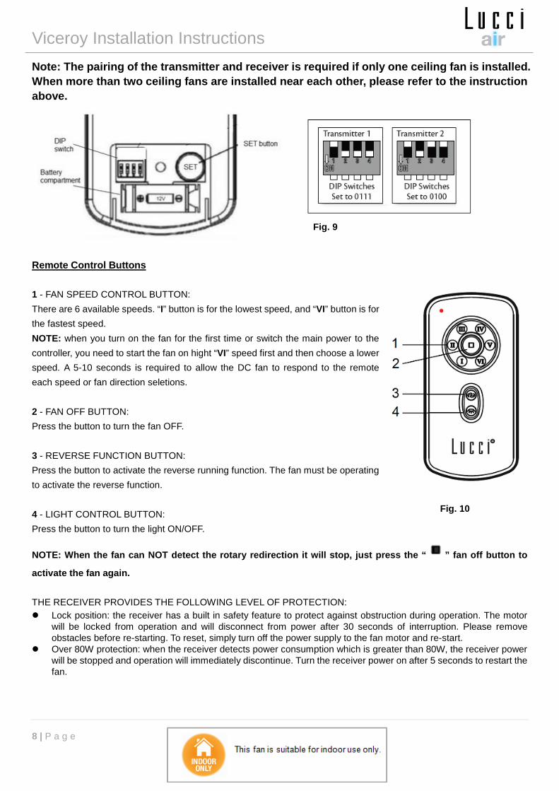
Slide the cover of the battery compartment of the transmitter to access the DIP switches. This will be transmitter 1. Fig.9
Change the position of the DIP switches in the remote transmitter 1, so that it will be different to transmitter 2.
Install the 12V DC battery in the compartment. Please make sure the polarity of the battery is correct.
Turn on the power to receiver 1. Keep the power OFF to receiver 2. (Each ceiling fan must have its own isolation switch, so that only the ceiling fan that needs to be paired with the transmitter will be ON).
Press and hold the “SET” button of transmitter 1 for 3-5 seconds within 60 seconds of switching the power ON to the receiver of ceiling fan 1.
The fan will move slightly and stop to indicate the paring process is activated.
If the fan has light kit attached, the light will flash on and off to indicate the paring process activated.
Turn ON and change the speed of the ceiling fan 1 by the transmitter to check the operation and successful paring.
Transmitter / Receiver paring for Ceiling fan 2:
Turn off the mains supply to the receivers of both ceiling fans 1 and 2.
Slide the cover of the battery compartment of the transmitter to access the DIP switches. This will be transmitter 2. Fig.9
Change the position of the DIP switches in the remote transmitter 2, so that it will be different to transmitter 1.
Install the 12V DC battery in the compartment. Please make sure the polarity of the battery is correct.
Turn on the power to receiver 2. Keep the power OFF to receiver 1. (Each ceiling fan must have its own isolation switch, so that only the ceiling fan that needs to be paired with the transmitter will be ON).
Press and hold the “SET” button of transmitter 2 for 3-5 seconds within 60 seconds of switching the power ON to the receiver of ceiling fan 2.
The fan will move slightly and stop to indicate the paring process is activated.
If the fan has light kit attached, the light will flash on and off to indicate the paring process activated.
Turn ON and change the speed of ceiling fan 2 by the transmitter to check the operation and successful pairing.
Viceroy Installation Instructions
8 | P a g e
Note: The pairing of the transmitter and receiver is required if only one ceiling fan is installed. When more than two ceiling fans are installed near each other, please refer to the instruction above.
Remote Control Buttons 1 - FAN SPEED CONTROL BUTTON: There are 6 available speeds. “I” button is for the lowest speed, and “VI” button is for the fastest speed. NOTE: when you turn on the fan for the first time or switch the main power to the controller, you need to start the fan on hight “VI” speed first and then choose a lower speed. A 5-10 seconds is required to allow the DC fan to respond to the remote each speed or fan direction seletions. 2 - FAN OFF BUTTON: Press the button to turn the fan OFF. 3 - REVERSE FUNCTION BUTTON: Press the button to activate the reverse running function. The fan must be operating to activate the reverse function. 4 - LIGHT CONTROL BUTTON: Press the button to turn the light ON/OFF.
NOTE: When the fan can NOT detect the rotary redirection it will stop, just press the “ ” fan off button to
activate the fan again. THE RECEIVER PROVIDES THE FOLLOWING LEVEL OF PROTECTION: Lock position: the receiver has a built in safety feature to protect against obstruction during operation. The motor
will be locked from operation and will disconnect from power after 30 seconds of interruption. Please remove obstacles before re-starting. To reset, simply turn off the power supply to the fan motor and re-start.
Over 80W protection: when the receiver detects power consumption which is greater than 80W, the receiver power will be stopped and operation will immediately discontinue. Turn the receiver power on after 5 seconds to restart the fan.
Fig. 10
Fig. 9

Viceroy Installation Instructions
9 | P a g e
REPAIRING THE FAN RECEIVER & REMOTE PAIRING Should the remote and receiver lose control after installation or during use, the pairing of the remote and the receiver must be repaired. Below are the operating symptoms and method to repair the pairing of the DC ceiling fan remote and receiver. Issues: Loss of control - Fan is only running at high speed after installation Loss of control - No reverse function after installation Loss of control - Remote cannot communicate with receiver
Solution:
A. Switch OFF the main power to ceiling fan for 30 seconds.
B. Press and hold the “SET” button on transmitter for 3-5 seconds within 60 seconds of switching the power ON to the receiver of the ceiling fan.
C. Turn ON and change the speed of the ceiling fan via the transmitter to check the operation and successful paring.
AFTER INSTALLATION WOBBLE: NOTE: ceiling fans tend to move during operation due to the fact that they are mounted on a rubber grommet. If the fan was mounted rigidly to the ceiling it would cause excessive vibration. Movement of a few centimetres is quite acceptable and DOES NOT suggest any problem. TO REDUCE THE FAN WOBBLE: Please check that all screws which fix the mounting bracket and down rod are secure. BALANCING KIT: A balancing kit is provided to balance the ceiling fan on initial installation. Please refer to the instruction on how to use the balancing kit. The balancing kit can be used to assist re-balancing should the ceiling fan become un-balanced again. Store your balancing kit away after installation for future use if required. NOISE: When it is quiet (especially at night) you may hear occasional small noises. Slight power fluctuations and frequency signals superimposed in the electricity for off-peak hot water control, may cause a change in fan motor noise. This is normal. Please allow a 24-hour “breaking-in” period, most noises associated with a new fan disappear during this time. All electric motors are audible to some extent. Please note that this is not a product fault, and as such is not coverd under warranty. CARE AND CLEANING: Periodic cleaning of your ceiling fan is the only maintenance required. Use a soft brush or lint free cloth to avoid
scratching the paint finish. Please turn off electricity power when you do so. Do not use water when cleaning your ceiling fan. It could damage the motor or the blades and create the possibility
of an electrical shock. The motor has a permanently lubricated ball bearing so there is no need to oil. NOTE: Always turn OFF the power at the mains switch before attempting to clean your fan.

Viceroy Installation Instructions
10 | P a g e
TECHNICAL INFORMATION
FAN models Rated Voltage Rated power (motor) Battery for remote
VICEROY FAN 220-240VAC 35W 1 x 12V 23AE

Viceroy Installation Instructions
11 | P a g e
LUCCI CEILING FAN WARRANTY DETAIL LUCCI WARRANTY HOTLINE- 1800 602 243
THIS WARRANTY IS VALID IN AUSTRALIA ONLY In the event of service being required, please call the Lucci Fan Warranty Hotline on 1800 602 243 between 9am & 5pm
(EST) Monday to Friday. Please make sure you have all the ceiling fan details filled out at the end of the manual before
making the call. Every Lucci ceiling fan is thoroughly inspected and tested before being released for sale. In addition to any warranty
rights or conditions under statutory regulations, Lucci warrants all of its ceiling fans against defective workmanship and
faulty materials for twenty four (24) months from the date of purchase. Lucci undertakes, at its option, to repair or
replace, free of charge, each product or part thereof on condition that;
1. The fan or relevant part has not been subjected to misuse, neglect, or been involved in an accident.
2. The repairs are not required as a result of normal wear and tear.
3. The product was installed by a licensed electrical contractor.
4. A copy of the original receipt of purchase is presented.
5. 12 month warranty applies when used in any non-domestic applications.
6. This warranty does not cover stains, scratch and scuff marks, or dents if the product is purchased through a
factory outlet or to refurbished items.
Our goods come with guarantees that cannot be excluded under the Australian Consumer Law. You are entitled to a
replacement or refund for a major failure and compensation for any other reasonably foreseeable loss or damage. You
are also entitled to have the goods repaired or replaced if the goods fail to be of acceptable quality and the failure does
not amount to a major failure.
Lucci Design cannot be held responsible for any repair other than those carried out by it or one of its Authorised Service Agents. Please keep this warranty information in a safe place. This information must be produced in the event of service being required. Distributed by: Beacon Lighting
140 Fulton Drive
Derrimut, Victoria, 3030
Australia
Ph +613 9368 1000
Fax +613 9360 9332
Email: [email protected]
Viceroy Installation Instructions
12 | P a g e
CEILING FAN WARRANTY INFORMATION LUCCI WARRANTY HOTLINE- 1800 602 243
Complete and retain this form for your personal records and warranty purposes. NAME………………………………………………………………………………… ADDRESS…………………………………………………………………………… ……………………………………………………POSTCODE…………………… MODEL NUMBER……………………………………………………………………
(PO# + DATECODE Sticker here) PO NUMBER or DATECODE ……………………………………………………… DATE OF PURCHASE……………………………………………………………… INSTALLING LICENSED ELECTRICAN…………………………………………… ………………………………………………………………………………………… LICENCE No………………………………………………………………………… ATTACH PROOF OF PURCHASE HERE
THIS COMPLETED DETAIL PAGE SHOULD BE PRODUCED AND FAXED TO THE
WHOLESALER OR THEIR AUTHORISED AGENTS BEFORE OBTAINING
WARRANTY SERVICE