Lubrication of Optimized- - NASA · Lubrication of Optimized- Design Tapered-Roller Bearings to 2.4...
19
NASA Technical Paper 1714 Y Lubrication of Optimized- Design Tapered-Roller Bearings to 2.4 Million DN Richard J. Parker, Stanley I. Pinel, and Hans R. Signer 1 NASA TP 1714 1 c.1 1 1 , AUGUST 1980 https://ntrs.nasa.gov/search.jsp?R=19800021233 2018-09-06T15:32:54+00:00Z
Transcript of Lubrication of Optimized- - NASA · Lubrication of Optimized- Design Tapered-Roller Bearings to 2.4...
NASA Technical Paper 1714
Y
Lubrication of Optimized- Design Tapered-Roller Bearings to 2.4 Million DN
Richard J. Parker, Stanley I. Pinel, and Hans R. Signer
1 NASA TP 1714 1 c . 1 1
1 ,
AUGUST 1980
https://ntrs.nasa.gov/search.jsp?R=19800021233 2018-09-06T15:32:54+00:00Z

TECH LIBRARY KAFB, NM
I 111111 Ill11 lllll11lll1ll11 lllll lllll11ll Ill 0134891
NASA Technical Paper 1714
Lubrication of Optimized- Design Tapered-Roller Bearings to 2.4 Million DN
Richard J. Parker, Stanley I. Pinel, and Hans R. Signer Lewis Research Ceizter Cleveland, Ohio
*
NASA National Aeronautics and Space Administration
Scientific and Technical Information Branch
1980
J Summary Introduction Tapered-roller bearings are being used in some
helicopter transmissions to carry combined radial, thrust, and moment loads and, in particular, those loads from bevel gears such as high-speed input pin- ions. For this application tapered-roller bearings have greater load capacity for a given envelope or for a given bearing weight than the more commonly used ball and cylindrical roller bearings. But speed limita- tions have restricted the use of tapered-roller bear- ings to lower speed applications compared with ball and cylindrical-roller bearings. The speed limitation is primarily due to the cone-rib-roller-large-end con- tact, which requires very careful lubrication and cooling consideration for high speed operation. The speed of tapered roller bearings is limited to approx- imately 0.5 million DN (a cone-rib tangential velocity of approximately 36 m/sec (7000 ft/min)) unless special attention is given to lubricating and designing this cone-rib-roller-end contact. At higher speeds centrifugal effects starve this critical contact of lubricant.
By supplying lubricant directly to this critical con- tact through holes in the cone, tapered-roller bear- ings have been successfully operated to 1.81 million DN under heavy combined radial and thrust loads (ref. 1). Under thrust-load-only conditions (ref. 2) speeds as high as 3.5 million DN have been suc- cessfully attained.
The internal geometry of the bearings used in these tests (refs. 1 and 2) were standard catalog series designs with modifications of the roller spherical ends and lubrication holes through the cone. Also, some of the bearings used in reference 2 had cages designed for high-speed operation, and the rollers, cones, and cups were made of CBS l000M material.
The use of computer programs can increase the capability of designing and analyzing tapered-roller bearings for high-speed applications. These pro- grams, described in references 3 and 4, take into ac- count the difficulty of lubricating the contacts in high-speed tapered roller bearings and consider the effects of the elastohydrodynamic (EHD) films in these contacts. The analysis of reference 3 was used to select the internal geometry for the high-speed
The performance of 120.65" (4.7541.) bore computer optimized, high-speed design, tapered- roller bearings was investigated at shaft speeds to 20 000 rpm (2.4 million DN or cone-rib tangential velocities to 158 m/sec (31 200 f t lmin)) . Temperature distribution and bearing heat genera- tion were determined as functions of shaft speed, radial and thrust loads, lubricant flow rate, and lubricant inlet temperature. Lubricant was supplied through holes in the cone at both the large and small ends of the rollers. Test conditions included shaft speeds from 6000 to 20 000 rpm, radial loads from 13 300 to 26 700 N (3000 to 6000 Ib), thrust loads from 26 700 to 53 400 N (6000 to 12 000 lb), lubri- cant flow rates from 0.0038 to 0.0151 m3/min (1.0 to 4.0 gal/min), and lubricant inlet temperatures of 350 and 364 K (170" and 195" F). The test bearing design was computer optimized for high-speed operation. The lubricant was MIL-L-23699.
The high-speed-design tapered-roller bearing operated successfully at shaft speeds up to 20 000 rpm under heavy thrust and radial loads. Stable temperatures were reached, and no surface distress was observed within the range of conditions tested. Bearing temperatures and heat generation with the high-speed-design bearing were significantly less than those of a modified standard design bearing tested previously.
Bearing temperatures and heat generation in- creased as expected with increased shaft speed. The highest temperatures measured were at the cup outer surface. With increased lubricant flow rates at both the large and the small ends, bearing temperature decreased, and heat generation increased. A total flow rate as low as 0.01 14 m3/min (3.0 gal/min) gave stable operating temperatures at 20 000 rpm without excessive bearing heat generation. Decreasing oil-in temperature from 364 to 350 K (195" to 170" F) decreased bearing temperature 6 to 14 K (10" to 25" F). Cup cooling was effective in decreasing the high cup temperatures to levels equal to the cone temperature. The effect of load on bearing temperatures was very small relative to the effects of speed and flow rates.
design tapered roller bearing used for the research reported herein.
The objective of this research was to determine the operating characteristics, including temperature distribution and heat generation, of a computer op- timized, high-speed-design, 120.65-mm (4.75-in .) bore tapered roller bearing at speeds to 20 000 rpm (2.4 million DN). The cone-rib tangential velocity at this speed was 158 m/sec (31 200 ftlmin). Indepen- dent test variables were shaft speed, radial and thrust loads, lubricant flow rate, and lubricant inlet temperature. The results were compared with the operating characteristics of modified standard test bearings reported in references 1 and 5 .
Apparatus and Procedure Test Rig
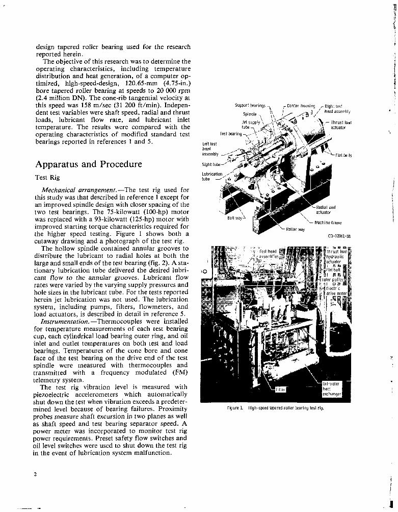
Mechanical arrangement.-The test rig used for this study was that described in reference 1 except for an improved spindle design with closer spacing of the two test bearings. The 75-kilowatt (100-hp) motor was replaced with a 93-kilowatt (125-hp) motor with improved starting torque characteristics required for
cutaway drawing and a photograph of the test rig. The hollow spindle contained annular grooves to
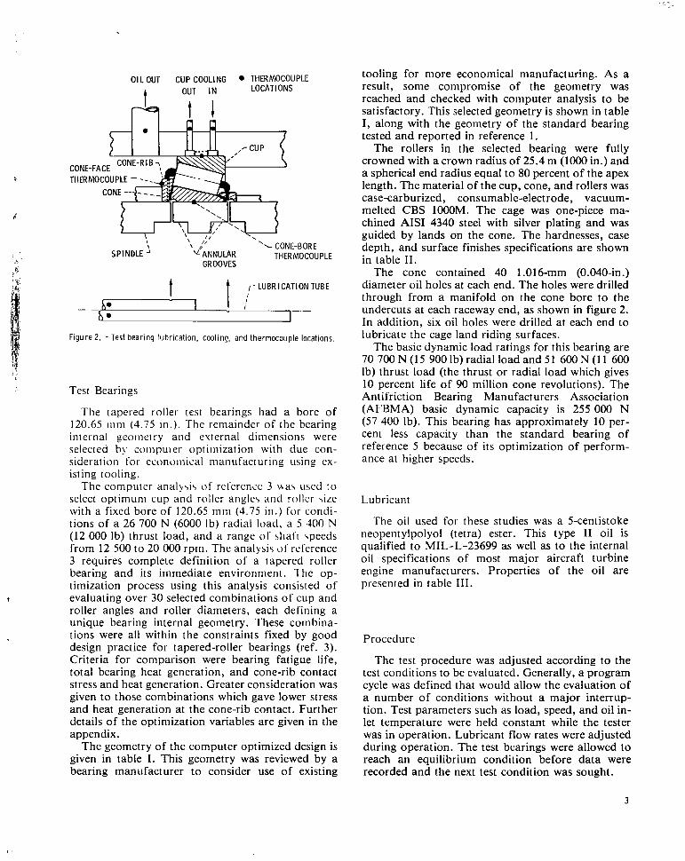
distribute the lubricant to radial holes at both the large and small ends of the test bearing (fig. 2). A sta- tionary lubrication tube delivered the desired lubri- cant flow to the annular grooves. Lubricant flow rates were varied by the varying supply pressures and hole sizes in the lubricant tube. For the tests reported herein jet lubrication was not used. The lubrication system, including pumps, filters, flowmeters, and load actuators, is described in detail in reference 5 .
Instrumentation. -Thermocouples were installed for temperature measurements of each test bearing cup, each cylindrical load bearing outer ring, and oil inlet and outlet temperatures on both test and load bearings. Temperatures of the cone bore and cone face of the test bearing on the drive end of the test spindle were measured with thermocouples and transmitted with a frequency modulated (FM) telemetry system.
The test rig vibration level is measured with piezoelectric accelerometers which automatically shut down the test when vibration exceeds a predeter-
probes measure shaft excursion in two planes as well as shaft speed and test bearing separator speed. A power meter was incorporated to monitor test rig power requirements. Preset safety flow switches and oil level switches were used to shut down the test rig in the event of lubrication system malfunction.
'- Machine frame
the higher speed testing. Figure 1 shows both a CD-12061-38
mined level because of bearing failures. Proximity Figure L - High-speed tapered roller bearing test rig.
L
,
I
OIL OUT CUP COOLING THERMCVX"XIJ LOCATIONS OUT IN t
?=? t l
, I 'L CONF-RllRE
SPINDLE IUPLE - - . . - - -. ,
ANNULAR THERMOCO GROOVES
r LUBRICATION TUBE
0 I h e
_ _ I
_ _
Test Bearings
The tapered roller test bearings had a bore of 120.65 iiini (4.75 in . ) . The remainder of the bearing internal geomerry and external dimensions were selected by coinpuier optiinization with due con- sideration for econuinical manufacturing uqing ex- isting tooling.
The computer analy\i\ of reference 3 mas used to select optimum cup and roller angles and roller \ire with a fixed bore of 120.65 m m (4.75 in . ) for condi- tions of a 26 700 N (6000 Ib) radial load. a 5 300 N (12 000 Ib) thrust load, and a range of shaft speeds from 12 500 to 20 OOO rpm. The analysi5 u t reference 3 requires complete definition of a tapered roller bearing and its immediate environment. The op- timization process using this analysis consisted of evaluating over 30 selected combinations of cup and roller angles and roller diameters, each defining a unique bearing internal geometry. These combina- tions were all within the constraints fixed by good design practice for tapered-roller bearings (ref. 3) . Criteria for comparison were bearing fatigue life, total bearing heat generation, and cone-rib contact stress and heat generation. Greater consideration was given to those combinations which gave lower stress and heat generation at the cone-rib contact. Further details of the optimization variables are given in the appendix.
The geometry of the computer optimized design is given in table I . This geometry was reviewed by a bearing manufacturer to consider use of existing
1
tooling for more economical manufacturing. As a result, some compromise of the geometry was reached and checked with computer analysis to be satisfactory. This selected geometry is shown in table I , along with the geometry of the standard bearing tested and reported in reference 1.
The rollers in the selected bearing were fully crowned with a crown radius of 25.4 m (loo0 in.) and a spherical end radius equal to 80 percent of the apex length. The material of the cup, cone, and rollers was case-carburized, consumable-electrode, vacuum- melted CBS 1OOOM. The cage was one-piece ma- chined AIS1 4340 steel with silver plating and was guided by lands on the cone. The hardnesses, case depth, and surface finishes specifications are shown in table 11.
The cone contained 40 1.016-mm (0.040-in.) diameter oil holes at each end. The holes were drilled through from a manifold on the cone bore to the undercuts at each raceway end, as shown in figure 2. In addition, six oil holes were drilled at each end to lubricate the cage land riding surfaces.
The basic dynamic load ratings for this bearing are 70 700 N (1 5 900 Ib) radial load and 5 1 600 N (1 1 600 lb) thrust load (the thrust or radial load which gives 10 percent life of 90 million cone revolutions). The Antifriction Bearing Manufacturers Association (AFBMA) basic dynamic capacity is 255 000 N (57 400 Ib). This bearing has approximately 10 per- cent less capacity than the standard bearing of reference 5 because of its optimization of perform- ance at higher speeds.
Lubricant
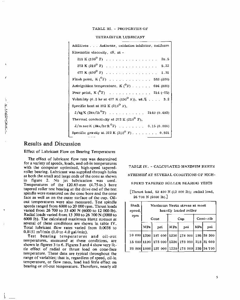
The oil used for these studies was a 5-centistoke neopentylpolyol (tetra) ester. This type I1 oil is qualified to MIL-L-23699 as well as to the internal oil specifications of most major aircraft turbine engine manufacturers. Properties of the oil are presented in table 111.
Procedure
The test procedure was adjusted according to the test conditions to be evaluated. Generally, a program cycle was defined that would allow the evaluation of a number of conditions without a major interrup- tion. Test parameters such as load, speed, and oil in- let temperature were held constant while the tester was in operation. Lubricant flow rates were adjusted during operation. The test bearings were allowed to reach an equilibrium condition before data were recorded and the next test condition was sought.
3
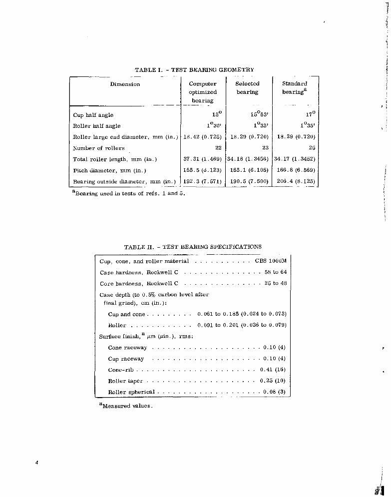
TABLE I . - TEST BEARING GEOMETRY .- _.. ..
Dimension
.- - -
Cup half angle
Roller half angle
Roller large end diameter, mm (in. )
Number of rollers
Total roller length, mm (in.)
Pitch diameter, mm (in.)
Bearing outside diameter, mm (in.) ~ .. __
Computer optimized bearing -
15O
1'30'
18.42 (0.725)
22
37.31 (1.469)
155.5 (0.123)
192.3 (7.571)
aBearing used in tests of refs. 1 and 5.
. . . .
Selected bearing
- ..
15'53l
1'35'
18.29 (0.720)
23
54.18 (1.3456)
155.1 (6.105)
190.5 (7.500) . __. - .-
Standard bearinga
.
17'
1'35
18.29 (0.720
2i
54.17 (1.3452
166.8 (6.569
206.4 (8.125 ~ ._
TABLE II. - TEST BEARING SPECIFICATIONS . _ _ -
Cup, cone, and roller material . . . . . . . . . . . CBS lOO0M
Case hardness, Rockwell C . . . . . . . . . . . . . . . 58 to 64
Core hardness, Rockwell C . . . . . . . . . . . . . . . 25 to 48
Case depth (to 0.5% carbon level after final grind), em (in.):
Cup and cone. . . . . . . . . 0.061 to 0.185 (0.024 to 0.073)
Roller . . . . . . . . . . . . 0.091 to 0.201 (0.036 to 0.079)
Surface finish, a pm (pin. ), rms:
Cone raceway . . . . . . . . . . . . . . . . . . . . . 0.10 (4)
Cup raceway . . . . . . . . . . . . . . . . . . . . . 0.10 (4)
Cone-rib . . . . . . . . . . . . . . . . . . . . . . . 0.41 (16)
Roller taper . . . . . . . . . . . . . . . . . . . . . 0.25 (10)
Roller spherical . . . . . . . . . . . . . . . . . . . . 0.08 (3)
aMeasured values.
4
i
!
TABLE III. - PROPERTIES OF
TETRAESTER LUBRICANT
Additives . . . Antiwear, oxidation inhibitor, antifoam
Kinematic viscosity, cS, at - 311 K (looo F) . . . . . . . . . . . . . . . . 28.5
372 K (210° F) . . . . . . . . . . . . . . . . 5.22
477 K (400' F) . . . . . . . . . . . . . . . . 1.31
Flash point, K ( O F ) . . . . . . . . . . . . . 533 (500)
Autoignition temperature, K ( O F ) . . . . . . 694 (800)
Pour point, K (OF) . . . . . . . . . . . . . 214 (-75)
Volatility (6.5 h r at 477 K (400' F)), wt.% . . . . 3.2
Specific heat at 372 K (210° F),
J/kg K (Btu/lb O F ) . . . . . . . . . . . 2140 (0.493)
Thermal conductivity at 372 K (210' F),
J / m s e c K (Btu/hrft°F) . . . . . . . . 0.15 (0.088)
Specific gravity at 372 K (210' F) . . . . . . . . 0.931 L - ~
Results and Discussion Effect of Lubricant Flow on Bearing Temperatures
The effect of lubricant flow rate was determined for a variety of speeds, loads, and oil-in temperatures with the computer optimized, high-speed tapered- roller bearing. Lubricant was supplied through holes at both the small and large ends of the cone as shown in figure 2. No jet lubrication was used. Temperatures of the 120.6" (4.7541.) bore tapered roller test bearing at the drive end of the test spindle were measured on the cone bore and the cone face as well as on the outer surface of the cup. Oil- out temperatures were also measured. Test spindle speeds ranged from 6000 to 20 000 rpm. Thrust loads
Radial loads varied from 13 300 to 26 700 N (3000 to 6OOO Ib). The calculated maximum Hertz stresses at several of these conditions are shown in table IV. Total lubricant flow rates varied from 0.0038 to 0.0151 m3/min (1.0 to 4.0 gal/min).
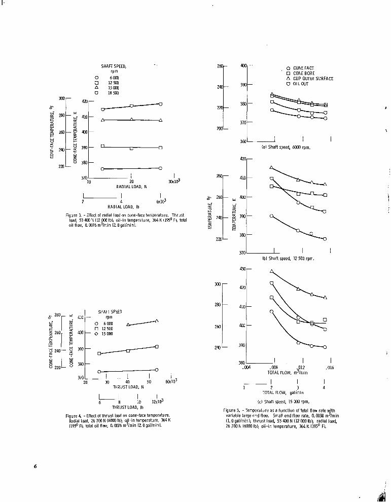
Test bear ing t empera tu res a n d oi l -out temperatures, measured at these conditions, are shown in figures 3 to 6. Figures 3 and 4 show very lit- tle effect of radial or thrust load on cone-face temperature. These data are typical throughout the range of variables; that is, regardless of speed, oil-in temperature, or flow rates, load had little effect on bearing or oil-out temperature. Therefore, nearly all
-7 varied from 26 700 to 53 400 N (6OOO to 12 000.Ib).
TABLE IV. - CALCULATED MAXIMUM HERTZ
STRESSEEf AT SEVERAL CONDITIONS OF HIGH-
SPEED TAPERED ROLLER BEARING TESTS
[Thrust load, 53 400 N (12 000 lb); radial load, 26 700 N (6000 lb).]
Shaft speed, heavily loaded rol ler
Maximum Hertz stress at most
Cone-rib
MPa ps i MPa MPa psi
187 000 1230 178 000 195 28 300
15 000 1190
20 000 1080
5
SHAFT SPEED, rpm
0 6000 0 1 2 m A 15000 0 1 8 m
U Y
P
I 6x10³
u 2 4
RADIAL LOAD, Ib
Figure 3. - Effect of radial load on cone-face temperature. Thrust load. 53 403 N 112 000 Ibl; oil-in temperature, 364 K (195' F); total oil flow. 0. W76 m3/min (2 Ogallmin).
370 L 20
SHAFT SPEED
0 2; / 0 125W 0 15000
M 40 50 THRUST LOAD, N
1 6 0 ~ 1 0 ~
I 1 I 6 8
THRUST LOAD, Ib
Figure 4 -Effect of thrust load on cone-face temperature. Radial load. 26 700 N (6000 Ib); 0'1 in temperature, 364 K (195OFI; total oil flow. am76 m G i n (LOgal/min).
. 0 CONEFACE 0 CONEBORE A CUP OUTER SURFACE
- 390 0 OILOUT
-
370r I I - I
-
360 (a) Shaft speed, 6000 rpm.
420r
410
CL 3 c
n
c c
380 220
:I 260
240
370 1 I (b) Shaft speed, 12 500 rpm.
400
390
I .016
380 L I , I f004 .W8 .012
TOTAL FLOW, m3/min
I I I I 1 2 3 4
TOTAL ROW. gallmin
(c) Shaft speed, 15 WO rpm.
Figure 5. - Temperature as a function of total flow rate with variable large end flow. Small end flow rate, 0.0038 m3/min (1 0 gallmin); thrust load. 53 400 N (12 OOO Ib); radial load. 26 7W N (6000 Ib); oil-in temperature, 364 K (195' F).
6
4hc
360 - 450
340 -
440
320 - 4%
300- 420
280 410 -
260 - 4w
280-
260
240
I 1 - 1 (dl Shaft speed, 18 500 rpm.
-
-
240
220
m
280
2 a
LL
O 243 2
4
3
5 w
2
410 t
012 .016 I
.008 TOTAL FLOW, m3/m:n
le) Shaft speed, 20 OOO rpm.
Figure 5. - Concluded.
370 (a) Shaft speed, 6 OOO rpm.
FACE 0 CONE BORE
3 (b) Shaft speed, 12 500 rpm. I-
430r-
m
260 f 240 L 3 9 0 1
.016 I
.012 380 I
.a04 . a08 TOTAL FLOW, m3/min
I I I I 1 2 3 4
TOTAL FLOW, gallmin
(c) Shaft speed, 15 OOO rpm.
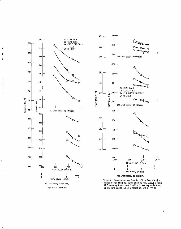
Figure 6. - Temperature as a function of total flow rate ith
(2 Ogallmin); thrust load. 53 400 N (12 OOO Ib); radial load, 26 700 N (6 OOO Ibl; oil-in temperature, 364 K (195’ F).
variable small end flow. Large end flow rate, a 0076 m 7 . lmin
7
450
440-
430-
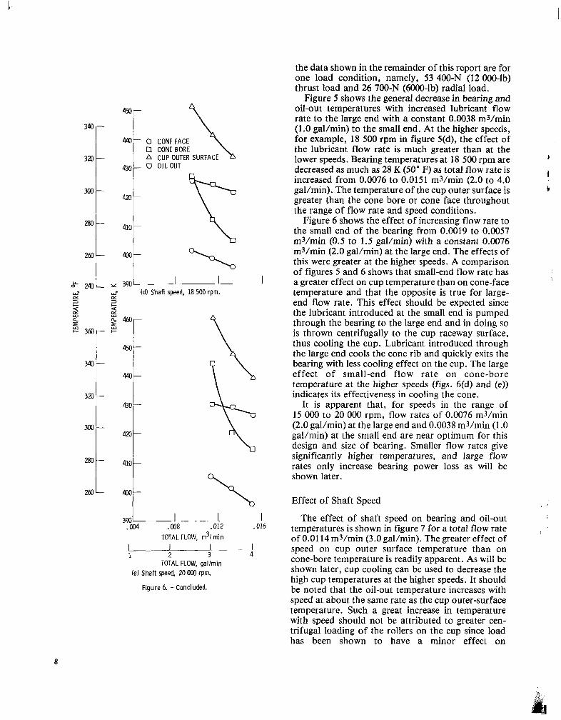
rate to the large end with a constant 0.0038 m3/min (1.0 gallmin) to the small end. At the higher speeds, for example, 18 500 rpm in figure 5(d), the effect of the lubricant flow rate is much greater than at the
decreased as much as 28 K (50" F) as total flow rate is
0 CONEBORE lower speeds. Bearing temperatures at 18 500 rpm are b
-
0 CONEFACE
A CUP OUTER SURFACE 0 OILOUT
340
320
300-
280-
260
300 :: 280 260
-
-
-
430
420 i 4 1 0 1
.004 .008 .012 .016
TOTAL FLOW, m3/ m i n I p I I _ _ _ - l 1 2 3 4
TOTAL FLOW, gal lmin (e) Shaft speed, 20 OOO rpm.
F igure 6. - Concluded.
thus cooling the ccp. Lubricant introduced through the large end cools the cone rib and quickly exits the bearing with less cooling effect on the cup. The large effect of small-end flow rate on cone-bore temperature at the higher speeds (figs. 6(d) and (e)) indicates its effectiveness in cooling the cone.
It is apparent that, for speeds in the range of 15 OOO to 20 000 rpm, flow rates of 0.0076 m3/min (2.0 gal/min) at the large end and 0.0038 m3/min ( 1 .O gal/min) at the small end are near optimum for this design and size of bearing. Smaller flow rates give significantly higher temperatures, and large flow rates only increase bearing power loss as will be shown later.
Effect of Shaft Speed
The effect of shaft speed on bearing and oil-out temperatures is shown in figure 7 for a total flow rate of 0.01 14 m3/min (3.0 gal/min). The greater effect of speed on cup outer surface temperature than on cone-bore temperature is readily apparent. As will be shown later, cup cooling can be used to decrease the high cup temperatures at the higher speeds. It should be noted that the oil-out temperature increases with speed at about the same rate as the cup outer-surface temperature. Such a great increase in temperature with speed should not be attributed to greater cen- trifugal loading of the rollers on the cup since load has been shown to have a minor effect on
8

300 ::: 343
320
m- L L
d B n
5 c 2@-
240
220
370 5000 10 ooo 1 5 0 0 0 2oooO
SHAFT SPEED, r p m 4% -
-
4 4 -
- 430 -
420 - x
d 2 410- L P
400-
390 - -
380 - -
Figure 7. - Effect of shaft speed on bear ing and o i l -ou t tem- peratures. T h r u s t load, 53 400 N (12 000 Ib); radial load. 26 700 N (6000 Ib); o i l - i n tem erature. 364 K (195' F);
end flow rate, 0.0038 m l m i n ( L O g a l l m i n ) .
large end flow rate, 0.0976.. 3 . lmin ( 2 0 g a l l m i n ) smal l
temperature. Also, since the cage is guided on lands on the cone, greater heat generation at those guiding surfaces at higher speeds is expected, along with higher cone temperature. Apparently, the lubricant flow through the holes in the cone (both large and small ends) very adequately cools the cone, and by the time it reaches the cup raceway, it has been heated appreciably and has less cooling capacity.
The test bearing cage speed was measured at all shaft speed conditions. The ratio of cage speed to shaft speed did not vary more than 1 percent from a nominal value of 0.445 throughout the range of speed, load, and lubricant flow conditions.
Stable operating temperatures were achieved at all speed, load, and lubricant flow rate conditions. Some of the lower lubricant flow rate points were not attempted at 20 OOO rpm due to anticipated excessive temperatures. Observations of the bearings after tests at 20 OOO rpm showed no signs of surface distress on the roller-raceway or roller/cone-rib contacting sur- faces. Likewise, cage contacting surfaces showed no abnormal wear or distress.
OIL-IN TEMPERATURE,
K (Of)
- 350 (1701 364 (1951 ---
0 CONEFACE 0 CONE BORE A CUP OUTER SURFACE 0 OILOUT -
360 I I (a) Shaft speed, 12 500 rpm.
3@ r r
I 0 J 012 ,016
370 1 I .004 .008
TOTAL FLOW, m3imin u 3 4
I 2
I 1
TOTAL FLOW; gallmin
(bl Shafl speed, 18 500 rpm.
out temperatures. Thrust load. 53 400 N (12 OOO Ib); r dial load. 26 700 N (6000 Ib); small end flow rate, Cl 0038 m'knin ( L 0 gallm in ).
f igure 8 - Effect of oil-in temperature on bearing and oil-
9
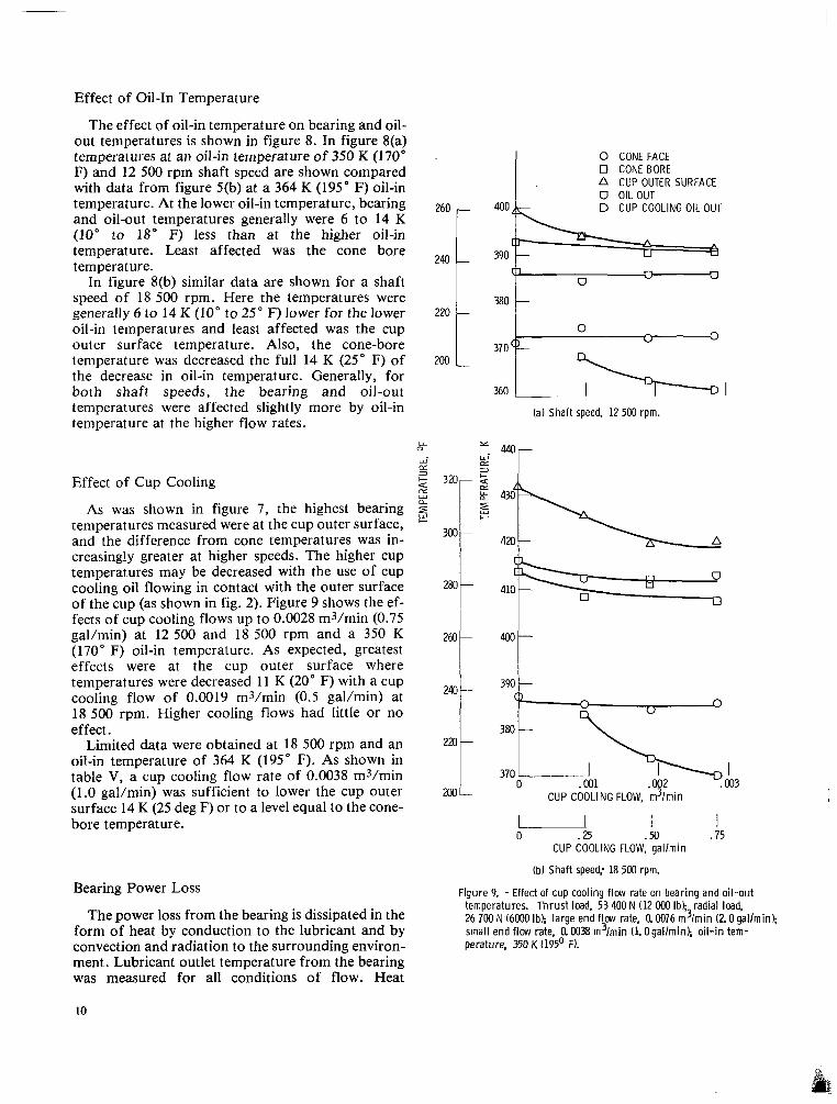
Effect of Oil-In Temperature
The effect of oil-in temperature on bearing and oil- out temperatures is shown in figure 8. In figure 8(a) temperatures at an oil-in temperature of 350 K (170" F) and 12 500 rpm shaft speed are shown compared with data from figure 5(b) at a 364 K (195" F) oil-in temperature. At the lower oil-in temperature, bearing and oil-out temperatures generally were 6 to 14 K (10" to 18" F) less than at the higher oil-in temperature. Least affected was the cone bore temperature.
In figure 8(b) similar data are shown for a shaft speed of 18 500 rpm. Here the temperatures were generally 6 to 14 K (10" to 25" F) lower for the lower oil-in temperatures and least affected was the cup outer surface temperature. Also, the cone-bore temperature was decreased the full 14 K (25" F) of the decrease in oil-in temperature. Generally, for both shaft speeds, the bearing and oil-out temperatures were affected slightly more by oil-in temperature at the higher flow rates.
Effect of Cup Cooling
As was shown in figure 7, the highest bearing temperatures measured were at the cup outer surface, and the difference from cone temperatures was in- creasingly greater at higher speeds. The higher cup temperatures may be decreased with the use of cup cooling oil flowing in contact with the outer surface of the cup (as shown in fig. 2). Figure 9 shows the ef- fects of cup cooling flows up to 0.0028 m3/min (0.75 gal/min) at 12 500 and 18 500 rpm and a 350 K (170" F) oil-in temperature. As expected, greatest effects were at the cup outer surface where temperatures were decreased 11 K (20" F) with a cup cooling flow of 0.0019 m3/min (0.5 gal/min) at 18 500 rpm. Higher cooling flows had little or no effect.
Limited data were obtained at 18 500 rpm and an oil-in temperature of 364 K (195" F). As shown in table V, a cup cooling flow rate of 0.0038 m3/min (1.0 gal/min) was sufficient to lower the cup outer surface 14 K (25 deg F) or to a level equal to the cone- bore temperature.
Bearing Power Loss
The power loss from the bearing is dissipated in the form of heat by conduction to the lubricant and by convection and radiation to the surrounding environ- ment. Lubricant outlet temperature from the bearing was measured for all conditions of flow. Heat
0 CONEFACE 0 CONE BORE A CUP OUTER SURFACE 0 OIL OUT
400 D CUP COOLING OIL OUT
390 - 380 P-- 360 3701A;----_,
(a) Shaf t speed, 12 500 rpm.
"r
T 390
F igu re 9. - Effect of cup cool ing flow rate on bear ing a n d o i l - ou t temperatures. T h r u s t load. 53 400 N (12 OOO Ib); radial load, 26 700 N (6000 Ib); large end f low rate, 0,0076 m3/m in (2. Ogal lmin) ; smal l e n d f low rate, a0038 m3/min (LOga l lm in ) ; o i l - i n tem- perature, 350 K (195' F).
CUP COOLING FLOW, m3/m in
1 .75
I I 0 .25 .50
CUP COOLING FLOW, g a l l m i n
(bJ Shaf t speed; 18 500 rpm.
10
I II
Cone face
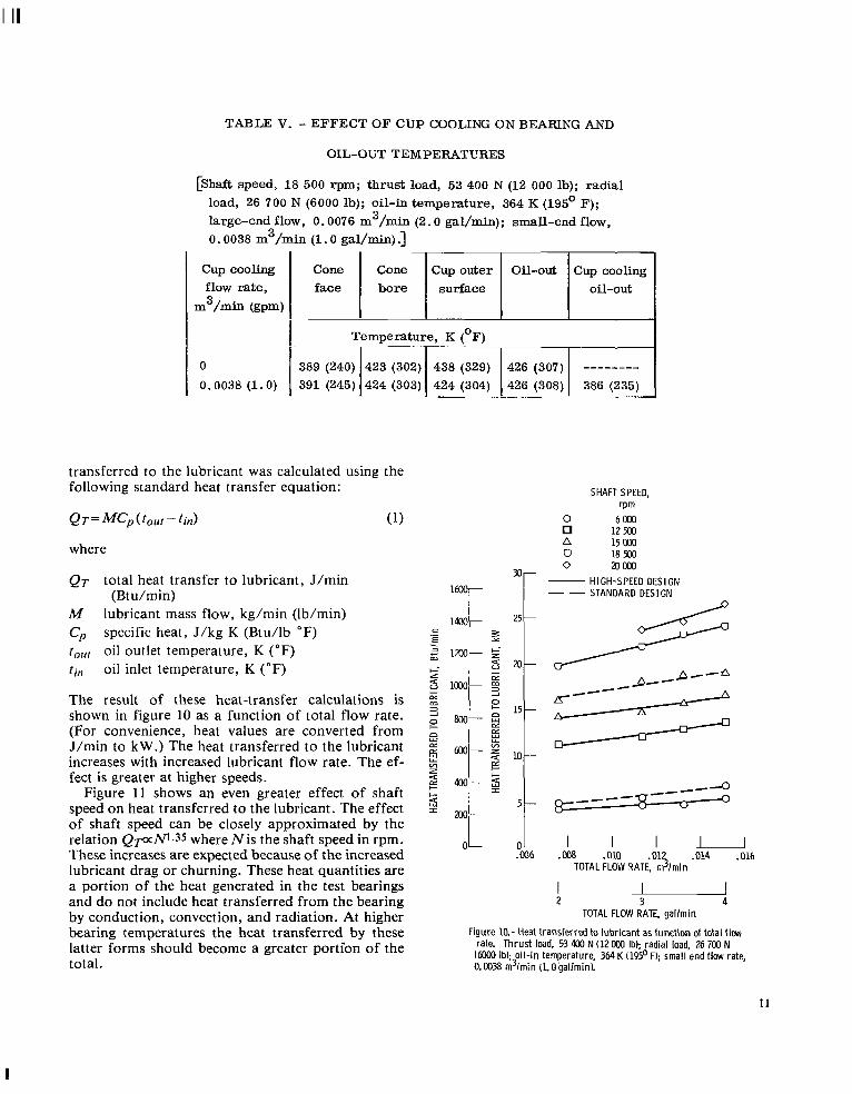
TABLE V. - EFFECT OF CUP COOLING ON BEARING AND
OIL-OUT TEMPERATURES
[Shaft speed, 18 500 rpm; thrust load, 53 400 N (12 000 lb); radial load, 26 700 N (6000 lb); oil-in temperature, 364 K (195' F);
0.0038 m3/min (1.0 gal/min) .] large-end flow, 0.0076 m 3 /min (2.0 gal/min); small-end flow,
Cone Cup outer Oil-out Cup cooling bore surface oil-out
cup cooling flow rate,
m3/- (ppm)
0 0.0038 (1.0)
I
transferred to the lubricant was calculated using the following standard heat transfer equation:
where
QT total heat transfer to lubricant, J/min
M lubricant mass flow, kg/min (Ib/min) C, specific heat, J/kg K (Btu/lb OF) to,,, oil outlet temperature, K (OF) ti,, oil inlet temperature, K ( O F )
The result of these heat-transfer calculations is shown in figure 10 as a function of total flow rate. (For convenience, heat values are converted from J/min to kW.) The heat transferred to the lubricant increases with increased lubricant flow rate. The ef- fect is greater at higher speeds.
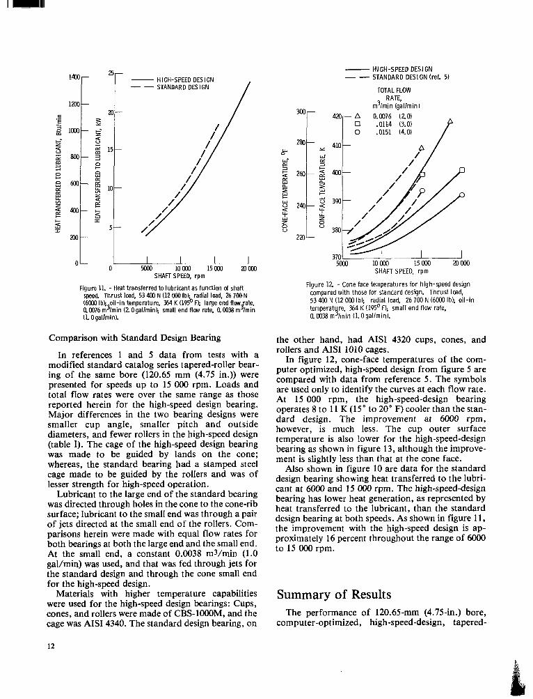
Figure 11 shows an even greater effect of shaft speed on heat transferred to the lubricant. The effect of shaft speed can be closely approximated by the relation Q~aRn.35 where Ni s the shaft speed in rpm. These increases are expected because of the increased lubricant drag or churning. These heat quantities are a portion of the heat generated in the test bearings and do not include heat transferred from the bearing by conduction, convection, and radiation. At higher bearing temperatures the heat transferred by these latter forms should become a greater porti'on of the total.
(Bt u/min)
SHAFT SPEED, rp m
0 6000 12 500
n 15 Mx) 0 18 m 0 20000
HIGH-SPEED DESIGN 1mr- STANDARD DESIGN
OL D l I I ! ~-' .@I6 .008 .010 .01\ , .014 .016
TOTAL FLOW RATE, m /min
TOTAL FLOW RATE, gal lmin
Figure 10.- Heat transferred to lubricant as funct ion of total f l m rate. Thrust load, 53 400 N (12000 Ib); radial load, 26 700 N (Eo00 Ib); oil- in temperature, 364 K (195' F); small end flow rate, 0.003 m3/min ( ~ 0 6 a l / m i n ) .
11
I
5 t
- HIGH-SPEED DESIGN STANDARD DESIGN --
L L l 1 I 0 m 10000 15000 20000
0
SHAFT SPEED, rpm
Figure 1L - Heat transferred to lubricant as function of shafl speed. Thrust load, 53 400 N (12 Mx) Ib); radial load. 26 700.N (6000 Ib); oil-in temperature, 364 K (195' F); large end flow ate,
(LOgallmin). 40076 m3/min (20gal lmink small end flow rate, a0038 m J . lmin
Comparison with Standard Design Bearing
In references 1 and 5 data from tests with a modified standard catalog series tapered-roller bear- ing of the same bore (120.65 mm (4.75 in.)) were presented for speeds up to 15 OOO rpm. Loads and total flow rates were over the same range as those reported herein for the high-speed design bearing. Major differences in the two bearing designs were smaller cup angle, smaller pitch and outside diameters, and fewer rollers in the high-speed design (table I). The cage of the high-speed design bearing was made to be guided by lands on the cone; whereas, the standard bearing had a stamped steel cage made to be guided by the rollers and was of lesser strength for high-speed operation.
Lubricant to the large end of the standard bearing was directed through holes in the cone to the cone-rib surface; lubricant to the small end was through a pair of jets directed at the small end of the rollers. Com- parisons herein were made with equal flow rates for both bearings at both the large end and the small end. At the small end, a constant 0.0038 m3/min (1.0 gal/min) was used, and that was fed through jets for the standard design and through the cone small end for the high-speed design.
Materials with higher temperature capabilities were used for the high-speed design bearings: Cups, cones, and rollers were made of CBS-lOOOM, and the cage was AISI 4340. The standard design bearing, on
- HIGH-SPEED DESIGN _ - STANDARD DESIGN (ref. 5)
TOTAL FLOW RATE,
m3/min (gallmin)
P A 0.0076 (2.0) 0 .0114 (3.0) 0 .a151 (4.0)
w 0 a Y
Y z ou
SHAFT SPEED, rpm
Figure 12 - Cone face temperatures for high-speed design compared with those for standard design. Thrust load. 53 400 N (12 OOO Ib); radial load, 26 700 N (6000 Ib); oil-in temperat re 364 K (195' F); small end flow rate, 0.0038 m Y lmin (. (1.0gallmin).
the other hand, had AISI 4320 cups, cones, and rollers and AISI 1010 cages.
In figure 12, cone-face temperatures of the com- puter optimized, high-speed design from figure 5 are compared with data from reference 5 . The symbols are used only to identify the curves at each flow rate. At 15 000 rpm, the high-speed-design bearing operates 8 to 11 K (15" to 20" F) cooler than the stan- dard design. The improvement at 6000 rpm, however, is much less. The cup outer surface temperature is also lower for the high-speed-design bearing as shown in figure 13, although the improve- ment is slightly less than that at the cone face.
Also shown in figure 10 are data for the standard design bearing showing heat transferred to the lubri- cant at 6000 and 15 OOO rpm. The high-speed-design bearing has lower heat generation, as represented by heat transferred to the lubricant, than the standard design bearing at both speeds. As shown in figure 11, the improvement with the high-speed design is ap- proximately 16 percent throughout the range of 6OOO to 15 OOO rpm.
Summary of Results The performance of 120.65" (4.75411.) bore,
computer-optimized, high-speed-design, tapered-
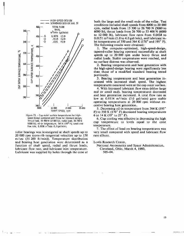
HIGH-SPEED DESIGN STANDARD DESIGN (ref. 51 --
460- TOTAL FLOW RATE, 3 ~ r I m3lmin (gallmin) n
A 0.0076 (2.0) 0 .0114 (3.0)
340 c 47- 0 .0151 (4.0)
240 L
E c 3 0 P x V
m 10 Mw) 15 000 20 000 SHAFT SPEED, r p m
Figure 13. - Cup outer surface temperatures for high- speed design compared wi th those for standard design. Thrust Imd. 53 400 N (12 OM] Ibl; radial load, 26 700 N (6000 Ib); oil-in te flow rate, Q 0 0 3 8 m I m i n (1.OgallminL
erature, 364 K (195' F); small end Y . roller bearings was investigated at shaft speeds up to 20 OOO rpm (cone-rib tangential velocitieg up to 158 m/sec (3 1 200 ft/min)). Temperature distribution and bearing heat generation were determined as a function of shaft speed, radial and thrust loads, lubricant flow rate, and lubricant inlet temperature. Lubricant was supplied by holes through the cone at
both the large and the small ends of the roller. Test conditions included shaft speeds from 6OOO to 20 OOO rpm, radial loads from 13 300 to 26 700 N (3000 to 6OOO lb), thrust loads from 26 700 to 53 400 N (6OOO to 12 000 Ib), lubricant flow rates from 0.0038 to 0.0151 m3/min (1 .O to 4.0 gal/min), and lubricant in- let temperatures of 350 and 364 K (170" and 195" F). The following results were obtained:
1. The computer-optimized, high-speed-design, tapered-roller bearing operated successfully at shaft speeds up to 20 OOO rpm under heavy thrust and radial loads. Stable temperatures were reached, and no surface distress was observed.
2. Bearing temperatures and heat generation with the high-speed-design bearing were significantly less than those of a modified standard bearing tested previously.
3. Bearing temperatures and heat generation in- creased with increased shaft speed. The highest temperatures measured were at the cup outer surface.
4. With increased lubricant flow rates (either large end or small end), bearing temperatures decreased and heat generation increased. A total flow rate as low as 0.0114 m3/min (3.0 gal/min) gave stable operating temperatures at 20 OOO rpm without ex- cessive bearing heat generation.
5 . Decreasing oil-in temperature from 364 K (195" F) to 350 K (170" F) decreased bearing temperatures 6 to 14 K (10" to 25" F).
6. Cup cooling was effective in decreasing the high cup temperature to levels equal to the cone temperature.
7. The effect of load on bearing temperatures was very small compared with speed and lubricant flow rate effects.
Lewis Research Center, National Aeronautics and Space Administration,
Cleveland, Ohio, March 4, 1980, 505-04.
13
... ._ . _ _ ~. .. ___.. . .... . . .,

Appendix-Optimization Variables
The computer optimization utilized the program described in reference 3. The bearing bore diameter was fixed at 120.65 mm (4.75 in.). Over 30 cases were evaluated using cup half angles a0 of 12", 15" and 18"; roller half angles Y of 1.0", 1.5" and 2.0"; and roller large end diameters ranging from 13.3 to 27.9 mm (0.525 to 1.100 in.).
Other dimensions which were fixed by good design practice (ref. 3) were
A = 5.08 mm (0.20 in.)
B = 5.08 mm (0.20 in.)
C=0.15 W
E=0.635 mm (0.025 in.)
R,= 0.8 LA
where R, is roller spherical end radius and LA is apex length,
Tw=0.2 Dm
where Tw is cage web thickness, and Dm is roller mean diameter,
h = 2.54 mm (0.10 in.)
where h is roller end-flange contact height. And
1.0 < L/D < 2.6
where L is total roller length and D is roller large end diameter. These dimensions are defined in figure 14.
Figure 14. - Tapered-roller bearing geometry.
14

References
1. Parker, R. J.; and Signer, H. R.: Lubrication of High-speed, bined Loading. (SKF-AL73POlO. SKF Industries, Inc.; NASA Contract NAS3-15700.) NASA CR-121207, 1973.
4. Cornish, Robert F.; Orvos, Peter S.; and Gupta, Shionarayan R.: Development of High Speed Tapered Roller Bearing. IR-1. Timken Roller Bearing Co., 1973.
5. Parker, R. J.; and Signer, H. R.: Performance of Large-Bore Tapered-Roller Bearings Under Combined Radial and Thrust Load at Shaft Speeds to 15 OOO rpm. NASA TN D-8404, 1977.
Large Bore Tapered Roller Bearings. J. of Lubr. Technol. vol. 100. no. 1, Jan. 1978, pp. 31-38.
2. Orvos, P. S.; and Dressler. G. J.: Tapered-Roller Bearing Development f o r A i rc ra f t Turb ine Engines . AFAPL-TR-79-20077 Air Force Aeropropulsion Lab'' 1979. (AD-A069440.)
3. Crecelius, W. J. ; and Milke, D. R.: Dynamic and Thermal
(AFAPL-TR-73-85, AD-771547.)
Analysis of High Speed Tapered Roller Bearings Under Com-
15
I -
4. Title and Subtitle
LUBRICATION O F OPTIMIZED-DESIGN TAPERED- ROLLER BEARINGS TO 2.4 MILLION DN
.- 7. Author(s1
Richard J. Parker , Stanley I. Pinel, and Hans R. Signer ,
9. Performing Organization Name and Address
National Aeronautics and Space Administration Lewis Research Center Cleveland, Ohio 44135
12. Sponsoring Agency Name and Address
National Aeronautics and Space Administration Washington, D. C. 20546
1. Report No.
NASA TP-1714 5. Report Date
August 1980 6. Performing Organization Code
8. Performing Organization Report No.
E - 270 10. Work Unit No.
505-04 11. Contract or Grant No.
13. Type of Report and Period Covered
Technical Paper 14. Sponsoring Agency Code
3. Recipient's Catalog No I I 2. Government Accession No.
I
15. Supplementary Notes
Richard J. Parker: Stanley I. Pinel and Hans R. Signer: Industrial Tectonics, Inc., Compton, California.
Lewis Research Center.
16. Abstract
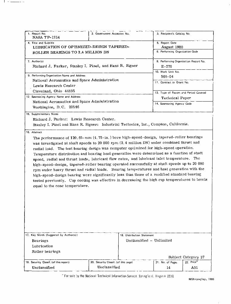
The performance of 120.65-mm (4.75-in. ) bore high-speed-design, tapered-roller bearings was investigated at shaft speeds to 20 000 rpm (2.4 million DN) under combined thrust and radial load. Temperature distribution and bearing heat generation were determined as a function of shaft speed, radial and thrust loads, lubricant flow rates, and lubricant inlet temperature. high-speed-design, tapered-roller bearing operated successfully at shaft speeds up to 20 000 rpm under heavy thrust and radial loads. Bearing temperatures and heat generation with the high-speed-design bearing were significantly less than those of a modified standard bearing tested previously. equal to the cone temperature.
The test bearing design was computer optimized for high-speed operation.
The
Cup cooling was effective in decreasing the high cup temperatures to levels
7. Key Words (Suggested by Authorls))
Bearings Lubrication Roller bearings
18. Distribution Statement
Unclassified - Unlimited i -_
9. Security Classif. (of this report) 20. Security Classif. (of this page) 21. No. of Pages 22. Price'
Unclassified Unclassified 14 A0 1
* For sale by the National Technical Information Service, Springfield, Virginia 22161 NASA-Langley, 1980
SPECIAL FOURTH CLASS M A I L BOOK
National Aeronautics and Space Administration
Washington, D.C. 20546 Official Business
Penalty for Private Use, $300
12 1 1u,c, 061380 SOO903DS DEPT OE THE AZB POBCE BP UEAPOlS LABCRATOBY ASTN: TECHNICAL L I B B A R Y {SUL) K I B T L B H O AFB NH 87117
NASA
I Postage and Fees Paid National Aeronautics and Space Administration NASA451
USMAIL
I
I '
POSTMAST~R: If Undeliverable (Section 158 Postal Manual) Do Not Return