Lubrication in cold rolling: elasto-plasto-hydrodynamic ... · the rolling force, which again...
12
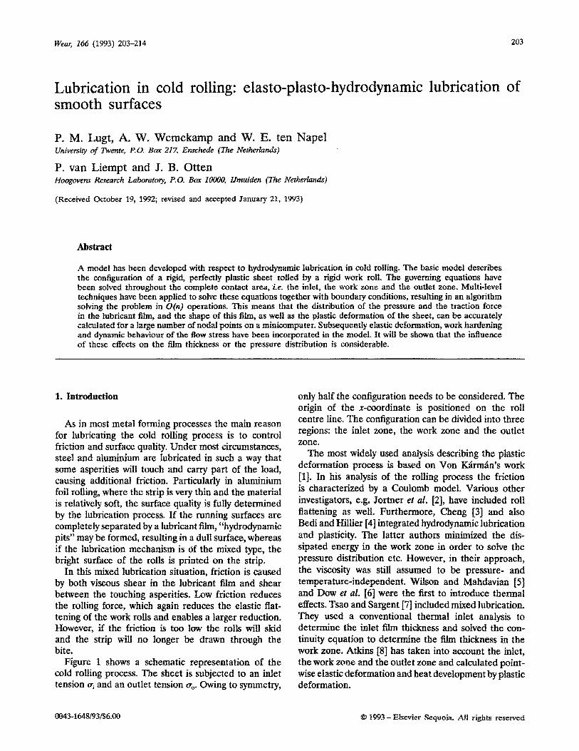
Wear, 266 (1993) 203-214 203 Lubrication in cold rolling: elasto-plasto-hydrodynamic lubrication of smooth surfaces P. M, Lugt, A. W. W~rn~k~rnp and W. E. ten Nape1 Universily ctf Twente, P.U. Box 217, Ens&de (The ~~t~er~a~j P. van Liempt and J. B. Otten Hoogovenr Research Laboratory, P.0. Box 10000, IJmuiden (The Ntderlandr) (Received October 19, 1992; revised and accepted January 21, 1993) Abstract A model has been developed with respect to h~rod~ami~ lubrication in cold roiIing. The basic model describes the configuration of a rigid, perfectly plastic sheet rolled by a rigid work roll. The governing equations have been solved throughout the complete contact area, ie. the inlet, the work zone and the outlet zone. Multi-level techniques have been applied to solve these equations together with boundary conditions, resulting in an algorithm solving the problem in O(n) operations. This means that the distribution of the pressure and the traction force in the lubricant film, and the shape of this film, as well as the plastic deformation of the sheet, can be accurately calculated for a large number of nodal points on a min~omputer. ~u~~qu~nt~ efastic defo~at~n, work pardoning and dynamic behaviour of the Bow stress have been incorporated in the model. It will be shown that the influence of these effects on the film thickness or the pressure distribution is considerable. As in most metal forming processes the main reason for lubricating the cold rolling process is to control friction and surface quality. Under most circumstances, steel and aluminium are lubricated in such a way that some asperities will touch and carry part of the load, causing additional friction. Particularly in aluminium foil rolling, where the strip is very thin and the material is relatively soft, the surface quality is fully determined by the lubrication process. If the running surfaces are completely separated by a lubricant film, “hydr~ynamic pits” may be formed, resulting in a dull surface, whereas if the lubrication mechanism is df the mixed type, the bright surface of the rolls is printed on the strip. In this mixed lubrication situation, friction is caused by both viscous shear in the lubricant film and shear between the touching asperities. Low friction reduces the rolling force, which again reduces the elastic flat- tening of the work rolls and enables a larger reduction. However, if the friction is too low the rolls will skid and the strip will no longer be drawn through the bite. Figure 1 shows a schematic representation of the cold rolling process. The sheet is subjected to an inlet tension pi and an outlet tension 0,. Owing to symmetry, only half the ~~fi~ration needs to be considered. The origin of the x-coordinate is positioned on the roI1 centre line. The configuration can be divided into three regions: the inlet zone, the work zone and the outlet zone. The most widely used analysis describing the plastic deformation process is based on Von K&n&n’s work [l]. In his analysis of the rolling process the friction is characterized by a Coulomb model. Various other investigators, e.g. Jortner et al. 121, have included roll flattening as well. Furthermore, Cheng /33 and also Bedi and Hillier [4] inte~ated hydrod~amic lub~cation and plasticity. The latter authors minimized the dis- sipated energy in the work zone in order to solve the pressure distribution etc. However, in their approach, the viscosity was still assumed to be pressure- and temperature-~de~e~dent. Wilson and ~ahdavian [S] and Dow et al. [6] were the first to introduce thermal effects. Tsao and Sargent [7] included mixed lubrication. They used a conventional thermal inlet analysis to determine the inlet fihn thickness and solved the con- tinuity equation to determine the f&n thickness in the work zone. Atkins [8] has taken into account the inlet, the work zone and the outlet zone and calculated point- wise elastic defo~ation and heat development by plastic deformation.
Transcript of Lubrication in cold rolling: elasto-plasto-hydrodynamic ... · the rolling force, which again...
Wear, 266 (1993) 203-214 203
Lubrication in cold rolling: elasto-plasto-hydrodynamic lubrication of smooth surfaces
P. M, Lugt, A. W. W~rn~k~rnp and W. E. ten Nape1 Universily ctf Twente, P.U. Box 217, Ens&de (The ~~t~er~a~j
P. van Liempt and J. B. Otten Hoogovenr Research Laboratory, P.0. Box 10000, IJmuiden (The Ntderlandr)
(Received October 19, 1992; revised and accepted January 21, 1993)
Abstract
A model has been developed with respect to h~rod~ami~ lubrication in cold roiIing. The basic model describes the configuration of a rigid, perfectly plastic sheet rolled by a rigid work roll. The governing equations have been solved throughout the complete contact area, ie. the inlet, the work zone and the outlet zone. Multi-level techniques have been applied to solve these equations together with boundary conditions, resulting in an algorithm solving the problem in O(n) operations. This means that the distribution of the pressure and the traction force in the lubricant film, and the shape of this film, as well as the plastic deformation of the sheet, can be accurately calculated for a large number of nodal points on a min~omputer. ~u~~qu~nt~ efastic defo~at~n, work pardoning and dynamic behaviour of the Bow stress have been incorporated in the model. It will be shown that the influence of these effects on the film thickness or the pressure distribution is considerable.
As in most metal forming processes the main reason for lubricating the cold rolling process is to control friction and surface quality. Under most circumstances, steel and aluminium are lubricated in such a way that some asperities will touch and carry part of the load, causing additional friction. Particularly in aluminium foil rolling, where the strip is very thin and the material is relatively soft, the surface quality is fully determined by the lubrication process. If the running surfaces are completely separated by a lubricant film, “hydr~ynamic pits” may be formed, resulting in a dull surface, whereas if the lubrication mechanism is df the mixed type, the bright surface of the rolls is printed on the strip.
In this mixed lubrication situation, friction is caused by both viscous shear in the lubricant film and shear between the touching asperities. Low friction reduces the rolling force, which again reduces the elastic flat- tening of the work rolls and enables a larger reduction. However, if the friction is too low the rolls will skid and the strip will no longer be drawn through the bite.
Figure 1 shows a schematic representation of the cold rolling process. The sheet is subjected to an inlet tension pi and an outlet tension 0,. Owing to symmetry,
only half the ~~fi~ration needs to be considered. The origin of the x-coordinate is positioned on the roI1 centre line. The configuration can be divided into three regions: the inlet zone, the work zone and the outlet zone.
The most widely used analysis describing the plastic deformation process is based on Von K&n&n’s work [l]. In his analysis of the rolling process the friction is characterized by a Coulomb model. Various other investigators, e.g. Jortner et al. 121, have included roll flattening as well. Furthermore, Cheng /33 and also Bedi and Hillier [4] inte~ated hydrod~amic lub~cation and plasticity. The latter authors minimized the dis- sipated energy in the work zone in order to solve the pressure distribution etc. However, in their approach, the viscosity was still assumed to be pressure- and temperature-~de~e~dent. Wilson and ~ahdavian [S] and Dow et al. [6] were the first to introduce thermal effects. Tsao and Sargent [7] included mixed lubrication. They used a conventional thermal inlet analysis to determine the inlet fihn thickness and solved the con- tinuity equation to determine the f&n thickness in the work zone. Atkins [8] has taken into account the inlet, the work zone and the outlet zone and calculated point-
wise elastic defo~ation and heat development by plastic deformation.

204 P. M. Lugt et al. I Lubrication in cold rolling
inlet zone work zone outlet zone
z t-
X
‘111 h ho -4
-. 4 Yl .- .... . . . . . . .._ . . . . . . . . . . . . . . . . . . . . . . . .
U Y-
fli -_--__ __--__-__.____ I Ye “z Qo _____--___---_ _________-
5 = 2, 5 = 2,
i
t 2
4 “&z
Fig. f. Representation of the components from the film thickness equation and a slab taken from the sheet.
Although asperity contact is important in analysing the rolling process, research is mainly focused on full film lubrication. The most commonly applied theory is from Wilson and Walowit [9]. They calculated pressure, film thickness and shear stress distribution by applying an analytical solution of the Reynolds equation in the inlet zone and solving the continuity equation in the work zone. Their well known film thickness formula is:
(1)
Research in this field over the last five years, has been focused on mixed lubrication models, where as- perity flattening plays a central role, As mentioned before, Tsao and Sargent [7] developed such a model in 1967. However, only the elastic flattening of the asperities, using the Hertzian theory, was considered.
Sheu [lo] was the first to introduce plastic flattening of asperities. He used an averaged Reynolds equation describing the lubricant flow and an upper bound approach for the plastic asperity deformation. Sutcliffe [ ll] improved this work by applying another deformation mode.
Film thickness always plays a central role in the different lubrication theories. If the film thickness is large, the asperities will not touch and friction will be low. On the other hand, if the film thickness is small, some asperities will touch and friction will be high. In order to calculate the part of the friction determined by asperity contact, the film thickness should be cal- culated accurately. In this paper it will be shown that, for instance, elastic deformation of the sheet in the inlet will result in fihn thicknesses significantly larger than found so far. As a result the real area of contact will be much smaller than assumed so far in the mixed lubrication models. This paper describes a basic model calculating pressure, film thickness and shear stress distribution by solving the Reynolds equation in the entire contact area, i.e. the inlet, the work zone and the outlet zone, in combination with plastic deformation using multigrid techniques. Incorporation of various effects, such as non-Newtonian fluid behaviour and elastic deformation of the sheet and roll can then relatively easily be incorporated. In this paper this wili be shown for the elastic deformation of the sheet. Moreover, these techniques make it possible to deal with surface defects like bumps, scratches etc.
2. Equations
The behaviour of the lubricant between the roll and the sheet can adequately be described by the Reynolds equation [ 121:
(2)
where p is pressure, h is film thickness, 77 is dynamic viscosity and U, is the average velocity. For the cold rolling situation this equation has to be rewritten, since the velocity of the strip surface is not constant. Assuming the metal deformation to be homogeneous, which holds in the case of cold rolling for reductions over 10% [13], this velocity can be derived using the continuity equation for the strip, (d/~)(~y) = 0, so the Reynolds equation reads:
(3)

P. M. f.agt et al. I hhication in cold mliing 205
with u for the local strip velocity, u1 Ear the initial strip velocity, y, for half the initial thickness of the strip, &d for twice the roil velocity and y for half the strip thickness.
The film shape can be represented by a parabola, approx~ati~g the shape of the roll, plus the plastic deformation of the strip d&z):
h(X) =h,+ (x2/2@ -F-y, -y(x) (4)
or
h(x) = h, + (x212R) -y(x) (5)
with izoo= k,+yt. Figure 1 shows this s~hemati~I1~~ A large h, corresponds to a large film thickness,
which causes a very low pressure in the lubricant film, whereas a decrease of boo results in an increase of pressure. faoo is chosen such that the inlet pressure equals the flow stress minus the prescribed value of the inlet tension. As a result the parameter hoa describes the vertical displacement of the roll, needed to supply the roll force, the so-called “screw setting”.
In the inlet zone, half the sheet thickness y is equal to the inlet thickness y,. In the work zone, half the sheet thickness is described by the well-known Von K&-m&n [1] equation.
With 7” (rl/h)[(u,,/2) -u] (Newtonian fluid), this equation reads:
In the outlet zone the sheet behaves rigidly again,
The viscosity of the lubricant is strongly pressure- dependent. The viscosity-pressure relation applied here in the first instance is the Barus [14] equation:
rl = 7ioe- (8)
Despite the fact that this relation overest~ates vis- cosities for high pressures 1151, it will be applied in order to be able to compare the results with those of Wilson and Walowit (91.
In the second part of the paper a more adequate relation, i.e. the Roelands relation [16], will be applied,
ri = r10 expC(ln q. + 9.67110 +pbr), - 111 (9 with pt = 1.962 X 10’ Pa.
The relation between E, (Y and rO is:
z =p,CYlfIn(?&J) + 9.671
4. Boundary conditions
Since the Reynolds equation predicts negative pres- sures in a diverging oil film, the so-called cavitation condition has to be fu~lled: p&O. As a result, the boundary for the pressure in the outlet will become a free bo~nda~: p = 0 at X&X,. In the inlet zone, far away from the gap, the pressure will equal the ambient pressure. So the second boundary for the pressure reads: x= - 00, p=O.
In the inlet acme, half the sheet thickness y is given
by Y ==Y,, The boundaries with respect to plastic deformation
can be derived using the Von Mises flow criterion together with the vertical force balance on a slab of the sheet: a, +p = uti In the inlet and outlet zone the horizontal stress a, must equal the inlet tension I and outlet tension a, respectively. As a result the plastic or work zone is bounded by:
x=x*, p=f&-CTi (101
X=X El P=%--@o WI
where X, and x, are the start and end of plastic de- formation respectively.
At the end of the work zone, plastic deformation will stop and the sheet will become rigid again. Hence the boundary condition regarding the sheet thickness at X=X, is a Neuman condition readingxax,, dy/&= 0.
The resulting equations and con~gurations are too complicated to enable analytical solution. Consequently, the equations will be discretized and solved numerically.
5. Multigrid techniques
To obtain an accurate solution and to be sure that surface roughness can be represented cm a grid, it will be necessary to calculate all variables on a large number of nodal points. Applicat~n~ of Co~~ent~onaI techniques, such as the widely used Newton-Rapbson system ap- proach, will require unacceptably large computer power, since the CPU time for this process is proportional to the second power of the number of nodal points (com- plexity is O(n’)). Therefore the multigrid method is used here in salving the cold rolling equations. The advantage of this method is that the complexity is about
O(n)*

206 P. M. Lugt et al. I Lubrication in cold rolling
This method has been applied to lubrication problems by Lubrecht [17] in solving so called EHL (elasto- hydrodynamic lubrication) problems. The solver for this problem has been greatly improved by Venner er al. 1181. The method will not be described here, but for a multigrid introduction the reader is referred to Briggs [19] and for a far more extended outline of these techniques to Brandt [ZO].
6. Preliminary results
In Figs. 2(a) and (b) a characteristic solution is plotted. The solution is calculated using 262 145 nodal points. The input parameters for this situation are listed in Table 1.
The film thickness is characterized by a sharp decrease in the inlet zone, while at the boundary of the inlet and work zone a sharp edge appears. This is the result of the sudden start of the deformation at this point. Elastic deformation of the sheet, as well as hardening,
0 70 / 0 80
__I / . 070 ,I\,
\; IO65 - . 060
-8 -7 -6 -5 -4 -3 -2 -1 0 1 2
(a) x[mml
0.67005 i- /
E E 0.67000
5:
P
&s” P
*& on
-w--w@--++ n* ++++ ++++
AA ++++ b”
++++ Y
++++
A” ++++ +++
0.57
0.56
d
B
0.66995 1 n *
-6.0325 -6.0320 -6.0315 -6.0310 -6 0305 -6.0300
(cl xlmml
0 60
0.59
0 58
has not been taken into account yet, as the deformation model describes rigid, perfectly plastic material be- haviour, so da,/& = 0.
Owing to the sharp decrease in film thickness, the pressure rise in the inlet zone is restricted to a small area where the pressure rises from zero to a,--~~.
The work zone is characterized by a slightly decreasing film thickness h, a decreasing sheet thickness and a non-constant pressure. In the case of constant surface velocities the film thickness would be expected to be nearly constant, as in EHL situations, since the shear (Couette) flow dominates the pressure (Pois~uiIle~ flow. Because of the increasing sheet velocity in the X- direction, however, the film thickness decreases slightly.
The shear stress, shown in Fig. 2(b), is positive near the inlet wedge of the work zone due to backward slip in this region. As the sheet velocity increases in the x-direction the slip decreases, resulting in a decreasing shear stress. At the location where the sheet velocity equals the roll velocity, the so called neutral point, the shear stress becomes zero, after which it becomes
I -3’
A-’ -8 --7 -6 -5 --4 -3 -2 -1 0
(b) x[mml
OEOl 0 50
0 40
0 30
0 20
0 10
11.
.._ 0 00
-009-007 -005 -003 -001 001 003 005 007
ldl x[mm]
Fig. 2. (a) Characteristic solution of sheet thickness y, pressure p and film thickness h; (b) characteristic solution of shear stress (working on the sheet) and horizontal stress distribution; (c) pressure and sheet thickness in an area of 2.5 ym around x,; (d) pressure and film thickness in an area of 0.16 mm around the line joining roll centres.

P. M. Lugt et al. / Lubrication in cold rolling 207
TABLE 1. Some parameters corresponding to the results pre- sented in Fig. 2
Parameter Value Dimension
262 145 0.670 0.597 0.246 0.251 0.223 25.0 586.8 0.0 65.0 0.587 1.38 ox@ 235 3292.6 - 6.03 - 2.49 - 0.069 0.02 0.5 x 10⁻⁸ 20.0 9.1
mm mm
pm Ir;m pm cm MPa MPa MPa GPa MPa
ICN m-’ mm mm mm Pa s Pa-’ m s-l m s-’
negative due to forward slip. The two peaks in the shear stress at the boundaries of the work zone are caused by the relatively large pressure flow due to a large pressure gradient.
In Fig. 2(c), the pressure and sheet thickness near the point where plastic deformation starts (X=X,) are plotted. The sharp edge in the pressure curve appears to be locally smooth, whereas the edge in the sheet thickness curve is sharp, due to the sudden start of deformation. Of course, the number of points used here is needlessly high for calculating an accurate solution. The large number used is merely intended to illustrate the possibilities of the developed algorithm with respect to future rough surface calculations.
In Fig. 2(d) the area around the line joining roll centres is enlarged. Plastic deformation stops at x= -0.06884 mm. Beneath the centre of the roll the material has become rigid again. As a result, the film thickness shows a dip in this area allowing a high negative pressure gradient. The figure also shows that the pressure gradient becomes zero when cavitation occurs.
According to the Wilson and Walowit [9] formula (1) the inlet film thickness h, =0.251 pm. This is in good agreement with the inlet film thickness calculated here &=0.246 pm.). This is no surprise, bearing in mind that the film thickness in a concentrated contact is mainly determined by the inlet zone. Wilson and Walowit assumed this inlet wedge to be straight. More- over, they assumed the pressure gradient at the start of plastic deformation to be zero. The results here
(Figs. 2(a) and (c)) show that both assumptions are appropriate. However, when the shear stress is increased by using an oil with a large pressure-viscosity coefficient a, a typical “pressure hill” will be found, making this assumption dubious.
In the following it will be shown that elastic defor- mation of the sheet and work hardening of the sheet influence the film thickness considerably.
7. Elastic defo~ation of the sheet in the inlet zone
In the following, an elastic-plastic material model will be used while the deformation will be assumed to be unifo~ over the thickness of the sheet, as in the foregoing. As a result, the sheet will deform elastically in the inlet zone, where the pressure rises gradually until the flow criterion is reached and plastic defor- mation occurs.
Owing to this elastic deformation, the sheet will “round in” somewhat, which results in a “smoother” inlet geometry. This deformation will probably be of the same order of magnitude as the film thickness at the entrance. Hence it can be expected that this will lead to a significant increase in film thickness.
Aggarwal and Wilson f21] were the first to discuss the effect of workpiece rounding on film thickness. They extended the work of Wilson and Murch [22], who incorporated thermal effects into Wilson and Wal- owit’s [9] work by allowing temperature differences between roll and sheet. Agganval and Wilson compared their calculated film thicknesses with experimentally obtained values from Azushima [23] and showed that their theory underestimates the film thicknesses by a factor of about five, even when the rolling speeds are low and temperature effects can be neglected. They postulated that this effect was due to plastic deformation of the workpiece in the inlet zone, the so-called “round- ing in” phenomenon,
Tsao and Wilson 1241 showed that this “rounding in” phenomenon does indeed lead to larger film thick- nesses. They assumed the sheet to round in by local plastic deformation on the surface before plastic bulk deformation. The inlet film thickness was calculated analytically as a function of the workpiece radius and it was shown that this effect might easily double the calculated inlet film thickness. They also performed experiments on a laboratory mill with fully lubricated strips. In these experiments rolling was stopped with the strip partially deformed and the strip removed by reversing the mill. The strip was then sectioned on a plane normal to the roll axis during rolling and examined under a 250x optical microscope. No appreciable rounding of the workpiece in the inlet zone was visible.

208 I’. M. Lugt et al. I Lubrication in cold rolling
The present work will show that an increase of film thickness can indeed be explained by this rounding in
phenomenon. However, this effect may not be due to plastic ,deformation but to elastic deformation of the workpiece. This also explains why Tsao and Wilson could not observe this phenomenon after their exper- iments.
An equation describing elastic defo~ation of the sheet can be derived by considering the force balance on a slab taken from the sheet. The derivation is similar to Von K&man’s equation, as described before. The only difference is that Von Mises’ flow criterion has been replaced by Hooke’s law.
7.1. k’etiical e~u~~ib~u~ In Fig. 1 a slab taken from the sheet is drawn. The
vertical force balance between pressure p and shear stress r gives
div u,= -p+rz =-p
where CL is the IocaI coefficient of friction defined as p=dp. (Note that y is the magnitude of half the strip thickness, whereas a subscript y, as in cy and ay, denotes the direction along the rolls.) The coefficient of friction and the slope of the sheet in the contact zone are small compared to 1, so their product can be neglected and the vertical force balance reads: rr,= -p.
zz. ~o~zon~u~ equil~~um The horizontal force balance results in:
(q+p) $ +y 2 +7=0 (13)
7.3. Shear stress In the work zone, the pressure flow can be neglected
because of low pressure gradients and high viscosities. In the inlet zone, however, the pressure gradient is very large, resulting in a substantial contribution of lubricant back flow to the viscous shear stress. As a result, the shear stress must contain both Couette and Poiseuille flow contributions:
= - ; g- f ; [u,,- (~lYl&)l (14)
Z4. Hori.zontai stress cr, In the inlet zone, where the deformation is elastic,
the relation between stress and strain is given by Hooke’s law.
Again, a plane strain situation is assumed (hence E,, =O), so from Hooke’s law then follows:
Introduction of E,= lnCyiyl) and substitution of the above equations into the horizontal force balance (13) results in:
This equation can be simplified by assuming the efastic strains to be small. Then y/y1 - 1 and so 1 + In&/
YJ -Y!Yl* As a result, eqn. (15) is reduced to:
l-2Y, p ---
v, y (16)
This equation will be called the elastic Von Karman equation.
8. Flow stress
To study the justification of the constant flow stress assumption (perfectly plasticmateria1) it can be replaced by a relation described by Van der Lugt [25].
The flow stress is considered to consist of a static and a dynamic part. The static part is a function of strain, while the dynamic part is a function of strain rate and temperature. The temperature is calculated by assuming the heat to be generated by plastic de- formation.
@U = US,,(E) + Gn(i, 73 (17)
where a, is the flow stress from the uniaxial tension test. The plane strain flow stress cr, is:
where
X C W y+ws
(e[(Vlz)+ Bslc - 1) + (pdo)ln 1 e -(vD)r
(19)

P. M. Lugt et al. / Lubrication in cold rolling 209
and
Values for the different parameters in these equations, as given in the nomenclature list, are obtained from [25]. The plastic strain can be expressed in terms of the sheet thickness y by subtracting the elastic strain, caused by workpiece rounding in the inlet, from the total strain:
e=Et*t-E,= -In(;) +I#= -(ys) (21)
Tbe strain rate is then
1 dr i= -&yl - -
Y2 k (22)
To calculate the temperature, a heat balance is formed, assuming an adiabatic situation and heat to be generated by plastic deformation only. This results in
dT uk 4 --__-- dx Y&l k
(23)
9. Numerical aspects
Again multigrid techniques have been used to solve the equations. In the inlet zone, the elastic Von I&m&n equation (eqn. (16)), the Reynolds equation (eqn. (3)) and the film thickness equation (eqn. (5)) are solved. In the work zone the Von K;irmBn equation (eqn. (7)), the Reynolds equation, the film thickness, the tem- perature equation (eqn. (23)) and the flow stress equa- tion (eqn. (18)) are solved. In the outlet zone the strip is assumed rigid and the film thickness and Reynolds equation are solved.
10. Results
Before presenting any results we would like to em- phasize the assumed full film lubrication situation, implying perfectly smooth running surfaces. The results presented show film thicknesses which are smaller than the roughness of many rolled surfaces and thus may
have little practical meaning. Nevertheless the calcu- lations do give a general indication of the amount of real contact by comparison of the calculated film thick- nesses with the average asperity height and provide a good starting point for mixed lubrication analysis. Also, the multigrid algorithm offers good possibilities to sim- ulate surface roughness interaction.
First, a characteristic solution, solved using 49 153 nodal points, will be presented. Next, the influence of the non-constant flow stress and elastic deformation of the sheet in the inlet on film thickness and pressure distribution will be studied.
Finally, a parameter study will be performed varying the inlet tension, the viscosity-pressure coefficient and the strip reduction.
Only the model problem is solved using a very large number of nodal points. The remaining calculations have been performed using 3073 nodal points in order to save CPU time and disk space.
The calculations have been restricted to steel rolling. In all calculations the start and the end of plastic deformation, x, and x, respectively, are taken constant. As a result, all calculations show the same reduction and flow stress distribution.
In Fig. 3(a) the solid curves represent the solutions for the pressure, the film thickness and the strip thickness (the dashed curve will be discussed later). This solution has been calculated using the input parameters from Table 2. The situation represents mediate gauge rolling of steel, lubricated by a Newtonian, low viscosity, mineral oil. The parameters with respect to the flow stress are given in the nomenclature list. The output parameters are presented in Table 3.
It can be seen that in the inlet zone the pressure rises very steeply from zero until plastic deformation starts. As the fihn thickness is very small compared to the sheet thickness, the latter shows the parabolic roll shape. Just before the line joining roll centres (x=0) the plastic deformation stops and the sheet becomes rigid.
The film thickness decreases very sharply in the inlet and remains almost constant in the work zone. Just beforex= 0 the film thickness shows a small dip, allowing a sharp drop of pressure.
The elastic deformation of the sheet in the inlet is very small compared with the plastic deformation, so it cannot be seen in Fig. 3(a). Therefore an enlargement around x =xS is drawn in Fig. 3(b). Owing to the elastic deformation of the strip in the inlet zone, the strip “rounds in”, making a larger lubricant flow possible. As a result the film thickness will be much larger than in the rigid situation,

P. M. Lugt et al. I .ubn’cation in cold rolling
-V
h-
-a 60
0 38
-a 55 0 990 L.
-a 75
(b)
-a 65
x [mm1 (0)
x lmml
a00
600
a00 I-
T ’
375 L--J
-ii -10 -9 -a ~7 -6 -5 -4 3
x lmml
-11 -10 -9 -a -7 -6 -5 -4 -3 2 I
(d) x [mm1
0 1
-20 r
k- _30 LA_-._ _~~___ 1~
-17 -10 -9 -a 7 -6 ~5 -4 -3
le) x [mm]
Fig. 3. (a) Solution for the conditions
2 -1 0
490
given in Tables 2 and 3 showing half the sheet thickness y, pressure p and film thickness h. The dashed line represents the pressure distribution when the flow stress is assumed to be constant. (b) Enlargement of (a) around the transition elastic-plastic deformation. (c) Temperature and flow stress for the same conditions as in (a). (d) Yield stress. 1 =static component, 2= temperature dependent part of the flow stress, 3=flow stress for a constant temperature. (e) Shear stress and horizontal stress distribution. The parameters are the same as in (a).
Close to the elastic-plastic transition the film thickness shows an S-shape. This is due to the almost constant pressure gradient in this zone and the rather sharp change in pressure gradient at the point where plastic deformation starts. In Section 10.3 this will be discussed in detail.
In Fig. 3(c) the temperature and the flow stress are plotted. As mentioned before, heat generation is as- sumed to be caused by plastic deformation only, resulting in a temperature rise after x=x,. Since the strain rate decreases in the work zone the temperature gradient will also decrease. Finally, when the outlet zone is

P. M. Lugt et al. / Lubrication in cold rolling 211
TABLE 2. Input parameters for the model probiem. The pa- rameters used with respect to the flow stress can be found in the Appendix
rise in the contact. The figure also shows that heat development does have a large influence on the flow stress.
Parameter
n
VP a
urd “1 R
Yt Ypo
:S
US Tl XS xe
Value
49153 0.009 1.96X 10-a 20 a.7 0.25 1.0x 10⁻³ 2.0x 10-a 500.0 210.0 0.3 378.0 -8.65 - 0.05
Dimension
Pa s Pa-’ m s-l m 5-l m m m MPa GPa
K mm mm
In Fig. 3(e) the shear stress and horizontal stress distributions are plotted. Owing to the con-constant flow stress, the pressures behind the neutral point are lower than in front of it. Consequently, the shear stress becomes very small here. Figure 3(e) shows a constant increase of the horizontal stress in the contact due to a constant decrease of pressure.
TABLE 3. Output from the model problem
Value
2674.2 0.3863 0.3464 0.8439 15.133 776.48 643.11 597.70 416.19 -3.27 0.066 0.399 26.15
Dimension
kN m-l
F cwn mm % MPa MPa MPa K mm
GPa MPa
To show the effect of the use of the flow stress eqn. (18) on film thickness and pressure the model problem has been calculated using both a constant and a non- constant flow stress. The pressure dist~bution for a constant flow stress is represented by the dashed curve in Fig. 3(a). The (constant) flow stress equals the flow stress at x=x, in the model problem, i.e. o, =776.5 GPa. Figure 3(a) shows that, owing to the decrease of the flow stress in the work zone, the pressure in this zone also decreases, resulting in a very large outlet tension. The pressure decrease for the constant flow stress case is, in the work zone, less pronounced. Consequently the shear stresses are also lower.
The inlet film thickness is, for both cases, practically the same. This is due to the fact that the film thickness is determined mainly by the inlet zone. In this zone, plastic deformation has not yet started.
10.3. In~~ence of elastic sheet defo~ation and flow stress on inlet film thickness
The influence of elastic deformation on film thickness is most pronounced when the pressure-viscosity coef- ficient (Y equals zero.
entered and the strain rate has become zero, the temperature has reached its maximum.
In Fig. 3(d) the total flow stress (2) and its static component (1) are plotted. The figure shows that the dynamic component causes the flow stress to decrease towards the outlet zone, partly due to the temperature
Two situations will be compared in this section, one using a constant flow stress (0;=775.25 MPa) and a rigid inlet geometry, and a situation where the flow stress formula (18) is used and elastic sheet deformation is included. Both situations have been calculated using 49 153 nodal points.
TABLE 4. Influence of the viscosity-pressure coefficient on inlet film thickness hi, inlet film thickness according to Wilson and Walowit h,, minimum film thickness h,i,, maximum coefficient of friction hu. maximum coefficient of friction using Barus divided by the maximum coefficient of friction using Roelands, and specific rolling force w (for all calculations the Barus relation has been used)
-
TPa-‘) hi hv kin (b4 (wQ (r*.m)
CLmax CL” W -
I-% (kN m-t)
0 0.151 0.0367 0.126 1.9x 10⁻⁴ 1.0 2392 0.490 x 10-s 0.226 0.0834 0.196 9.1 x 10⁻⁴ 2.1 2372 0.981 x lo-’ 0.292 0.1460 0.256 5.0 x 10⁻³ 3.3 2373 1.471 x10-s 0.356 0.2153 0.317 2.9 x lo-* 3.8 2364 1.870x 1O-8 0.408 0.2730 0.371 1.7x 10-r 4090

212 P. M. Lugt et al. I Lubrication in cold rolling
The sheet thickness, the film thickness and the pres- sure around the elastic-plastic transition are plotted in Fig. 4. In both cases plastic deformation starts at x,= - 8.65 mm. In the rigid inlet situation (dashed curves, subscript B) this is easy to see; the sheet thickness is constant in the inlet zone and the start of plastic deformation is characterized by a discontinuity in the sheet thickness gradient.
In the elastic-plastic analysis (solid curves, subscript A), where the sheet deforms elastically, the elas- tic-plastic transition is much smoother than in the rigid case. Owing to this workpiece rounding, the buckle in the film thickness disappears. Also, the pressure gradient is much smaller than in the rigid inlet situation. In the rigid situation the pressure gradient shows a discon- tinuity which, of course, can also be seen in the film
-6 75 -8.70 -8 65 8 60
xlmml Fig. 4. Influence of elastic sheet deformation and non-constant flow stress on pressure p, sheet thickness y and film thickness h around the transition between the inlet and the work zone. The solid curves and subscript A refer to the case where the sheet deforms elastically and the flow stress is non-constant. The subscript B and the dashed curves refer to the case where the inlet geometry is assumed to be rigid and the flow stress is assumed to be constant.
60 I T--- ‘_
/ 4 /
30 /
$
r 0 s 0 / -~ --
;; 2 I 1: =600MPa -.
s v1 2: ;’ = 550 MPa
.30 ~ 3: /.I = 500 MPa !
I 4: -’ = 450 MPa
I /
.I1 -10 -9 -8 -7 -6 -5 -4 -3 -2 -1 0 ,
(0) x lmml
thickness. Owing to the dynamic component in the flow stress and the elastic deformation of the sheet, the pressure and film thickness round off near X=X,.
In the rigid inlet and constant flow stress situation, the inlet film thickness is 0.041 pm, while in the elastic deformation and non-constant flow stress case it is 0.16 pm. Hence, these effects have a significant effect on film thickness and could very well explain the discrepancy between the calculations and experiments as described in the introduction. Moreover, when developing mixed lubrication models these effects should be included.
10.4. Varying the inlet tension In this section the inlet tension is varied, while the
remaining input parameters are the same as in the model problem (Table 2). The inlet tension is varied from 450 MPa up to 600 MPa in steps of 50 MPa.
Varying the inlet tension results in a varying inlet pressure. Since the viscosity is exponentially dependent on pressure, larger pressures result in larger shear stresses. This is shown in Fig. 5(a). Owing to this increase in shear stress a “pressure hill” gradually appears, as can be seen in Fig. 5(b), resulting in a decreasing outlet tension. The inlet film thickness is almost independent of the inlet tension.
10.5. Varying the v~cos~~~ress~re coe~cie~t The viscosity-pressure coefficient of the lubricant has
a large influence on the viscosity and so on the film thickness, the viscous shear stress and the pressure. In this section the Barus viscosi~-pressure relation is used to show the influence of the coefficient CL When applying Roelands’ relation the effect is less pronounced, but the trend remains the same.
An increase of tu causes an almost linear increase of film thickness. This would cause a decrease of the shear stress, being inversely proportional to the film thickness. However, owing to the exponential viscos-
o 8. , , ~
= 600 MPa I
’ 070’2: = 550 MPa
3: -I = 500 MPa I
1 4: = 450 MPa I 4
0 60
0 50
s a c 0 40
a
0 30
0 20
0 10
0 00
‘-- ._ 3 -_ .
/ /
. .
2 .- _
t - . . / /
.-! __J ._A. I .I. _-..,L 1 . !i .i -11 -10 -9 -8 -7 -6 -5 -4 -3 .2 1 0 1
ib) x lmml
Fig. 5. (a) Shear stress distribution with varying inlet tensions. (b) Pressure distribution with varying inlet tension.
P. M. Lugt et al. I Lubrication in cold rolling 213
-+T 0 60
t% 0.
0.40
-11 -10 .9 -6 -7 -6 -5 -4 -3 -2 -1 0 1 -11 -10 -9 -8 -7 -6 .5 -4 -3 -2 -1 0 1
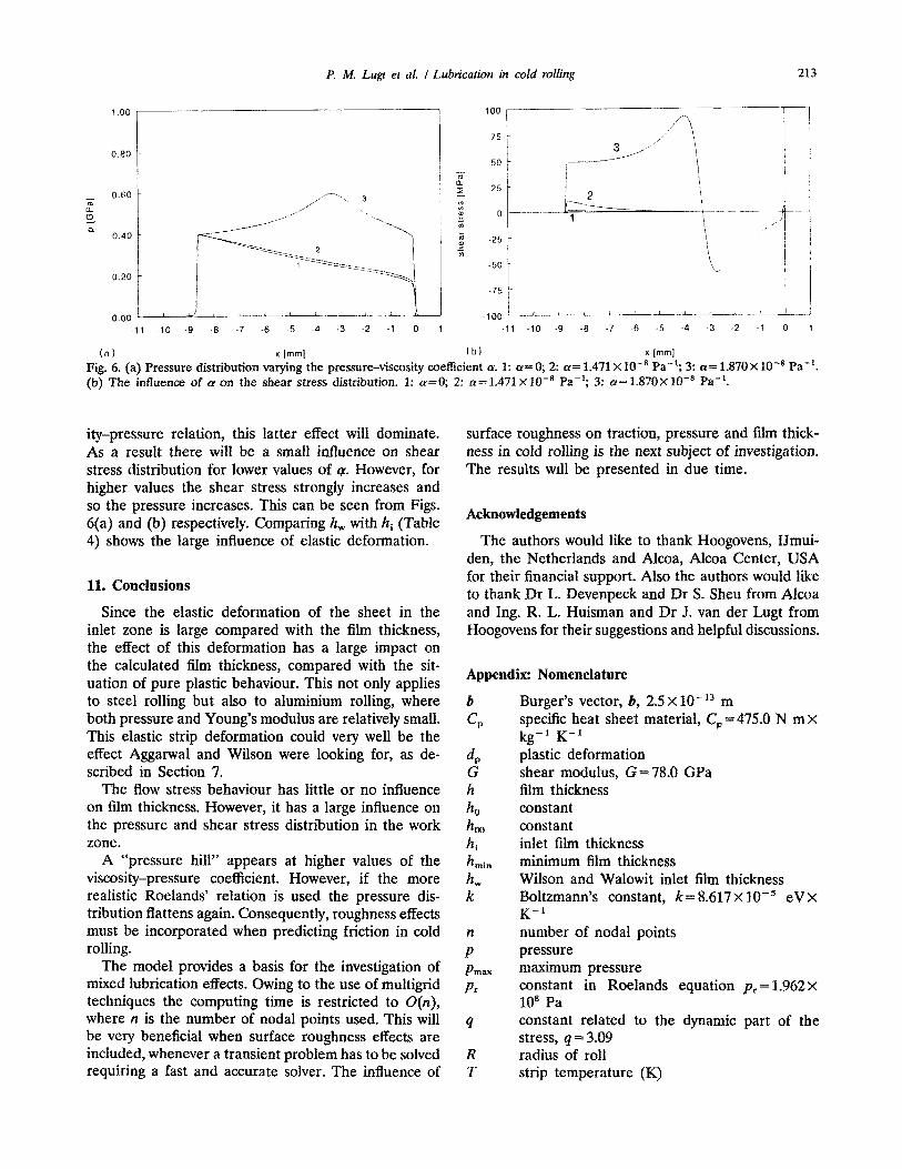
(a) x lmml (b) * Imml Fig. 6. (a) Pressure distribution varying the pressure-viscosity coefficient CY. 1: a=O; 2: (Y= 1.471 X 10V8 Pa-‘; 3: a= 1.870X 1O-8 Pa-‘. (b) The inffuence of cy on the shear stress distribution. 1: rr=O; 2: cy=1.471 X10-’ Pa-‘; 3: c~=1.87OXlO-~ Pa-‘.
ity-pressure relation, this latter effect will dominate. As a result there will be a small influence on shear stress distribution for lower values of q. However, for higher values the shear stress strongly increases and so the pressure increases. This can be seen from Figs. 6(a) and (b) respectively. Comparing h, with hi (Table 4) shows the large influence of elastic deformation.
11. Conclusions
Since the elastic deformation of the sheet in the inlet zone is large compared with the film thickness, the effect of this defo~ation has a large impact on the calculated film thickness, compared with the sit- uation of pure plastic behaviour. This not only applies to steel rolling but also to aluminium rolling, where both pressure and Young’s modulus are relatively small. This elastic strip deformation could very well be the effect Aggarwal and Wilson were looking for, as de- scribed in Section 7.
The flow stress behaviour has little or no influence on film thickness. However, it has a large influence on the pressure and shear stress distribution in the work zone.
A “pressure hill” appears at higher values of the viscosity-pressure coefficient. However, if the more realistic Roelands’ relation is used the pressure dis- tribution flattens again. ~n~quent~, roughness effects must be incorporated when predicting friction in cold rolling.
The model provides a basis for the investigation of mixed lub~cation effects. Owing to the use of multigrid techniques the computing time is restricted to O(n), where n is the number of nodal points used. This will be very beneficial when surface roughness effects are included, whenever a transient problem has to be solved requiring a fast and accurate solver. The influence of
surface roughness on traction, pressure and film thick- ness in cold rolling is the next subject of investigation. The results will be presented in due time.
The authors would like to thank Hoogovens, IJmui- den, the Netherlands and Alcoa, Alcoa Center, USA for their financial support. Also the authors would like to thank Dr L. Devenpeck and Dr S. Sheu from Alcoa and Ing. R. L. Huisman and Dr J. van der Lugt from Hoogovens for their suggestions and helpful discussions.
Appendix: Nomenclature
b
=,
4 G h
ho boo hi hmin k k
n
P P max
Pr
4
R T
Burger’s vector, b, 2.5 X lo-l3 m specific heat sheet material, C, = 475.0 N m X
kg-’ K-l plastic deformation shear modulus, G=78.0 GPa film thickness constant constant inlet film thickness minimum film thickness Wilson and Walowit inlet film thickness Boltzmann’s constant, k= 8.617 X 10m5 eV X K--l number of nodal points pressure maximum pressure constant in Roelands equation pr = 1.962 x 10’ Pa constant related to the dynamic part of the stress, q = 3.09 radius of roll strip temperature (K)

P. M. Lugt et al. I Lubn’cation in cold rolling
initial temperature, T, = 378.0 K temperature at x =x, local strip surface velocity initial strip surface velocity outlet strip surface velocity average velocity peripheral roll velocity double peripheral roll velocity, urd = 2u, load per unit width parameter related to dislocation, W= 2.724 x
10” m-’ deformation energy production coordinate left boundary of the work zone right boundary of the work zone cavitation boundary location of neutral point half thickness of the strip inlet half thickness of the strip outlet half thickness of the strip half thickness after hot rolling, ypO =2.0 X
10e3 m viscosity-pressure coefficient pressure coefficient of viscosity constant in flow stress equation, q= 0.82 parameter related to the ratio between apparent microscopic strain and macroscopic strain, &=0.174 maximum value of the activation free energy, AGO = 0.985 eV strain total strain elastic strain strain rate maximum strain rate, i. =3.95 X 10’ s-’ parameter related to dislocation production, y = 9.536 coefficient of friction maximum coefficient of friction in the work zone viscosity viscosity at ambient pressure and inlet tem- perature inlet tension plane strain flow stress outlet tension tensile stress yield stress from uniaxial tension test static part of flow stress dynamic part of flow stress stress maximum value of the dynamic equivalent stress = 1.085 GPa
UStO initial value of the static equivalent stress, independent of the dislocation density, usto = 137.88 MPa
P density (strip material), p = 7850 kg x m ’
PdO initial dislocation density, pdO = 2.0 x 10¹⁹ m -’ 7 shear stress 7 max maximum shear stress V poisson’s ratio
References
1
10
11
12 13
14 15
16
17
18
19
20
21
22
23
24
25
Th. Von Karrnan, Beitrag zur Theorie des Walzvorganges (Con- tribution to the Theory of Rolling), Vortrlge der Dresdener Tagung, Band 5, Heft 2, 1925. D. Jortner, J. F. Osterle and C. F. Zorowski, Int. J. Mech. Sci., 2 (1960) 179-194. H. S. Cheng, in Friction and Lubrication in Metal Processing, ASME, New York, 1966, pp, 69-80. D. S. Bedi and M. J. Hillier, Proc. ht. Mech. Eng. London, 182 (1967) 153-160. W. R. D. Wilson and S. M. Mahdavian, J. Lubr. Technol., 96 (4) (1974) 572-578. T. A. Dow, J. W. Kannel and S. S. Bupara, J. Lubr. Technol., 97 (1) (1975) 4-13. Y. H. Tsao and L. B. Sargent, Trans. ASLE, 21 (1976) 20-24. A. G. Atkins, Znt. J. Mech. Sci., 16 (1970) 1-19. W. R. D. Wilson and J. A. Walowit, in Tribology Convention 1971, Institute of Mechanical Engineers, London, 1971, pp. 164-172. S. Sheu, Ph.D. Thesis, Northwestern University, Evanston, IL, 1985. M. P. F. Sutcliffe, Proc. Inst. Mech. Eng. London, 204 (1990) 249-261. 0. Reynolds,Philos. Trans. R. Sot. London, I77( 1886) 157-234. P. Cosse and M. Economopoulos, CNRh4 Metall. Rep., 17 (1968) 15-32. C. Barus, Am. J. Sci., 45 (1893) 87-96. W. E. Ten Nape], H. Moes and R. Bosma, Proc. Inst. Mech. Eng. London, 185 (1971) 37-71. C. J. A. Roelands, Ph.D. Thesis, Technische Hogeschool Delft, The Netherlands, 1966. A. A. Lubrecht,Ph.D. Thesis, University of Twente, Enschede, 1987. C. H. Venner, W. E. ten Nape1 and R. Bosma, J. Lubr. Technol., 112 (1990) 426+32. W. L. Briggs, A Multigrid Tutorial, SIAM, Philadelphia, PA, 1987. A. Brandt, Multigrid Techniques: 1984 Guide with Applications to Fluid Dynamics, G.M.D., St Augustin 1, West Germany, 1984 (available as G.M.D.-Study No. 85, from G.M.D.-FIT, Postfach 1240, D-5205, St Augustin 1, Germany). B. B. Aggarwal and W. R. D. Wilson, in Proc. 5th Leeds-Lyon Symposium on Tribology, Institute of Mechanical Engineers, London, 1978, pp. 351-359. W. R. D. Wilson and L. E. Murch, J. Lubr. Technol., 98 (1976) 426-432. A. Azushima, in Froc. First Int. Conf on Lubrication Challenges in Metalworking and Processing, I.I.T.R.I., Chicago, IL, 1978, pp. 81-87. P. Tsao and W. R. D. Wilson, in Proc. Int. Conf Steel Rolling, Iron and Steel Institute of Japan, Tokyo, 1980, pp. 1143-1157. J. van der Lugt, Ph.D. Thesis, University of Twente, Enschede, The Netherlands, 1988.


![Untitled-1 [] · Rom 2 ROTA2 RO PLASTO CRAFTS Rom 2 ROTA2h ROTA2h PLASTO CRAFTS 2h . PLASTO PLASTO . 1 RCFø139 £26. 000 000 . Title: Untitled-1 Author: Ishaan Created Date: 3/20/2017](https://static.fdocuments.in/doc/165x107/5f51dbed91992003dd72a525/untitled-1-rom-2-rota2-ro-plasto-crafts-rom-2-rota2h-rota2h-plasto-crafts-2h.jpg)