
Lu-2014-Preparation of Hollow Silica Spheres by DC Thermal Plasma
8
Preparation of hollow silica spheres by DC thermal plasma Chen Lu a,b , Junmei Fan a , Peichen Zhao a , Fangli Yuan a, ⁎ a State Key Laboratory of Multi-phase Complex Systems, Institute of Process Engineering, Chinese Academy of Sciences, Beijing, PR China b University of Chinese Academy of Sciences, Beijing, PR China abstract article info Article history: Received 8 April 2014 Received in revised form 5 June 2014 Accepted 23 June 2014 Available online 30 June 2014 Keywords: Hollow silica spheres Spray drying DC thermal plasma sintering Cavity formation Hollow silica spheres (HSSs) are prepared via a two-step method: producing micrometer-sized agglomerated granules with nano-silica by spray drying and spheroidizing and hollowing the spray-dried granules (SDG) by DC thermal plasma sintering. The morphology, particle size distribution and porosity of SDG are affected by the solid concentration of the slurry. The shell structure and shell thickness of HSSs can be tuned by plasma sintering different kinds of SDG. The cavity formation mechanisms of two different types of HSSs, including single large void and multiple small voids are further investigated. The DC thermal plasma sintering method provides a facile way to produce HSSs with low density and high crush strength which have promising applications in many fields. © 2014 Elsevier B.V. All rights reserved. 1. Introduction Micrometer-sized hollow silica spheres (HSSs) have low specific gravity [1], desirable heat and sound insulating properties [2–4], high chemical stability, and good mechanical strength [5,6]. The importance and advantages of HSSs are shown not only in scientific fields but also in various industrial applications, such as heat-, sound-, water-, and oil- insulating composite materials, filler for catalyst carrier, light weight composite filler, pigments, buoyancy materials, and drilling fluids [7–10]. Various processing techniques for making HSSs of 5–200 μm in di- ameter have been developed, such as soft-template methods [11–13], hard-template methods [14,15], spray pyrolysis [16] and spray drying [17]. However, the shell of HSSs obtained by these methods is either po- rous or very thin, and the yield is relatively unsatisfactory, thus hampers some applications of HSSs, especially when used as a filler. As far as we know, thermal plasma processing provides unique advantages of high temperature, rapid quenching rate, high purity, and high yield rate, and some researchers have used it to produce hollow ceramic spheres with solid shell [18–20]. However, in these works, the mechanism of cavity formation is not clearly observed and the control of shell thickness is hard to achieve. In this present paper we describe the preparation of HSSs which have low density and high crush strength by DC thermal plasma sintering. In contrast to earlier works, we used spray drying technology to prepare micrometer-sized agglomerated granules without any or- ganic binder or blowing agent, and we tuned the mass content of silica to obtain spray-dried granules (SDG) with different morphology and porosity to further take control of the inner structure and shell thickness of the final HSSs. The morphology transition of SDG which was affected by the solid concentration of slurry was discussed. In addition, we further discussed the formation mechanisms of two different cavities of HSSs, in- cluding single large void and multiple small voids by SEM observation. 2. Materials and methods 2.1. Materials and preparation Silica slurry was prepared by mixing amorphous nano-silica (20 nm, An Hui Jing Ye Nano Technology Co., Ltd., China), silica sol (acting as binder, the solid content is 23.1%, AVIC Beijing Institute of Aeronautical Materials, China) and water with ball milling for a period of 2 h using a high speed agitated beads mill (220 rpm, using 5 mm zirconia ball, ball to material ratio is 3:1, Wuxi Xinguang Powder Processing Craft Co., Ltd., China). No dispersant or blowing agent was added into the slurry. The total silica concentration was varied from 5 wt.% to 30 wt.%, while the weight ratio of nano-silica to silica sol was kept at 10.0. The specific components of 10,000 g different kinds of slurry are shown in Table 1. The dryer used in this work is an industrial spray dryer (Dongsheng Spray-granulating and Drying Equipment Plant, Wuxi City, China). A schematic diagram of the spray drying system is shown in Fig. 1. The slurry was delivered by a peristaltic pump into a rotary atomizer (belt driven type; the atomizer disk is 50 mm in diameter with 12 uniformly distributed vanes), where centrifugal energy and friction force were in- troduced to atomize the slurry. Meanwhile, heated air entered the dry- ing chamber through a ceiling air disperser. The atomized droplets were propelled downward into a co-current flow of heated air which evaporated the water of the droplets. The SDG were collected at the bot- tom of the drying chamber. As the silica concentrations of the slurry Powder Technology 266 (2014) 210–217 ⁎ Corresponding author. Tel.: +86 10 82544925. E-mail address: fl[email protected] (F. Yuan). http://dx.doi.org/10.1016/j.powtec.2014.06.045 0032-5910/© 2014 Elsevier B.V. All rights reserved. Contents lists available at ScienceDirect Powder Technology journal homepage: www.elsevier.com/locate/powtec
description
Research paper
Transcript of Lu-2014-Preparation of Hollow Silica Spheres by DC Thermal Plasma

Powder Technology 266 (2014) 210–217
Contents lists available at ScienceDirect
Powder Technology
j ourna l homepage: www.e lsev ie r .com/ locate /powtec
Preparation of hollow silica spheres by DC thermal plasma
Chen Lu a,b, Junmei Fan a, Peichen Zhao a, Fangli Yuan a,⁎a State Key Laboratory of Multi-phase Complex Systems, Institute of Process Engineering, Chinese Academy of Sciences, Beijing, PR Chinab University of Chinese Academy of Sciences, Beijing, PR China
⁎ Corresponding author. Tel.: +86 10 82544925.E-mail address: [email protected] (F. Yuan).
http://dx.doi.org/10.1016/j.powtec.2014.06.0450032-5910/© 2014 Elsevier B.V. All rights reserved.
a b s t r a c t
a r t i c l e i n f oArticle history:Received 8 April 2014Received in revised form 5 June 2014Accepted 23 June 2014Available online 30 June 2014
Keywords:Hollow silica spheresSpray dryingDC thermal plasma sinteringCavity formation
Hollow silica spheres (HSSs) are prepared via a two-step method: producing micrometer-sized agglomeratedgranules with nano-silica by spray drying and spheroidizing and hollowing the spray-dried granules (SDG) byDC thermal plasma sintering. The morphology, particle size distribution and porosity of SDG are affected bythe solid concentration of the slurry. The shell structure and shell thickness of HSSs can be tuned by plasmasintering different kinds of SDG. The cavity formationmechanisms of two different types of HSSs, including singlelarge void andmultiple small voids are further investigated. The DC thermal plasma sintering method provides afacileway to produce HSSswith low density and high crush strengthwhich have promising applications inmanyfields.
© 2014 Elsevier B.V. All rights reserved.
1. Introduction
Micrometer-sized hollow silica spheres (HSSs) have low specificgravity [1], desirable heat and sound insulating properties [2–4], highchemical stability, and good mechanical strength [5,6]. The importanceand advantages of HSSs are shown not only in scientific fields but also invarious industrial applications, such as heat-, sound-, water-, and oil-insulating composite materials, filler for catalyst carrier, light weightcomposite filler, pigments, buoyancy materials, and drilling fluids[7–10].
Various processing techniques for making HSSs of 5–200 μm in di-ameter have been developed, such as soft-template methods [11–13],hard-template methods [14,15], spray pyrolysis [16] and spray drying[17]. However, the shell of HSSs obtained by thesemethods is either po-rous or very thin, and the yield is relatively unsatisfactory, thus hamperssome applications of HSSs, especially when used as a filler. As far as weknow, thermal plasma processing provides unique advantages of hightemperature, rapid quenching rate, high purity, and high yield rate,and some researchers have used it to produce hollow ceramic sphereswith solid shell [18–20]. However, in these works, the mechanism ofcavity formation is not clearly observed and the control of shellthickness is hard to achieve.
In this present paper we describe the preparation of HSSs whichhave low density and high crush strength by DC thermal plasmasintering. In contrast to earlier works, we used spray drying technologyto prepare micrometer-sized agglomerated granules without any or-ganic binder or blowing agent, and we tuned the mass content of silicato obtain spray-dried granules (SDG) with different morphology and
porosity to further take control of the inner structure and shell thicknessof thefinalHSSs. Themorphology transition of SDGwhichwas affected bythe solid concentration of slurry was discussed. In addition, we furtherdiscussed the formationmechanisms of two different cavities of HSSs, in-cluding single large void and multiple small voids by SEM observation.
2. Materials and methods
2.1. Materials and preparation
Silica slurry was prepared bymixing amorphous nano-silica (20 nm,An Hui Jing Ye Nano Technology Co., Ltd., China), silica sol (acting asbinder, the solid content is 23.1%, AVIC Beijing Institute of AeronauticalMaterials, China) and water with ball milling for a period of 2 h using ahigh speed agitated beads mill (220 rpm, using 5 mm zirconia ball, balltomaterial ratio is 3:1,Wuxi Xinguang Powder Processing Craft Co., Ltd.,China). No dispersant or blowing agent was added into the slurry. Thetotal silica concentration was varied from 5 wt.% to 30 wt.%, while theweight ratio of nano-silica to silica sol was kept at 10.0. The specificcomponents of 10,000 g different kinds of slurry are shown in Table 1.
The dryer used in this work is an industrial spray dryer (DongshengSpray-granulating and Drying Equipment Plant, Wuxi City, China). Aschematic diagram of the spray drying system is shown in Fig. 1. Theslurry was delivered by a peristaltic pump into a rotary atomizer (beltdriven type; the atomizer disk is 50 mm in diameter with 12 uniformlydistributed vanes), where centrifugal energy and friction force were in-troduced to atomize the slurry. Meanwhile, heated air entered the dry-ing chamber through a ceiling air disperser. The atomized dropletswere propelled downward into a co-current flow of heated air whichevaporated thewater of the droplets. The SDGwere collected at the bot-tom of the drying chamber. As the silica concentrations of the slurry

Table 1Component of different slurry.
Slurry name Nano-silica(g)
Silica sol(g)
Water(g)
Silica concentration(%)
SDG-5 488.74 48.87 9462.39 5SDG-10 977.49 97.75 8924.76 10SDG-15 1466.23 146.62 8387.15 15SDG-20 1954.98 195.50 7849.52 20SDG-30 2932.47 293.24 6774.29 30
Fig. 2. Schematic diagram of the DC thermal plasma sintering system.
211C. Lu et al. / Powder Technology 266 (2014) 210–217
were 5 wt.%, 10 wt.%, 15 wt.%, 20 wt.% and 30 wt.%, the obtained SDGare designated as SDG-5, SDG-10, SDG-15, SDG-20, and SDG-30, respec-tively. During the drying process the feedrate of slurry was set at100 mL/min, the speed of the rotary atomizer was kept at 15,000 rpm,and the inlet and outlet gas temperatures, which sometimes varywithin±2 °C, were 190 and 110 °C, respectively.
The next step is to sinter the SDG into a fully homogenized hollowstructure. This was accomplished by feeding the SDG into a high tem-perature DC plasma flame. The plasma system set up by our laboratoryconsisted of a plasma generator, a water-cooled reactor and a powder-collecting filter. A schematic illustration of the system is shown inFig. 2. The powder feeder was homemade and the feedrate could becontrolled by setting the flow of the carrier gas. In practical operation,the primary gas and secondary gas of the plasma generator were bothnitrogen; the power level might vary from 30 to 50 kW by adjustingthe voltage and the current of the plasma generator, and the feedrateof SDG might vary from 70 to 150 g/min depending on the particlesize of the SDG and the initial solid concentration of the slurry. Aftersintering we used water to pick out the floating product as final HSSs.
2.2. Characterization
The specimenswere dispersed intowater then observed by a biolog-ical microscope (Olympus, CX31), and the optical photographs weretaken by the attached CCD camera. The morphology and structure ofthe specimens were also observed by a scanning electron microscope(JEOL, JSM-6700F). The internal structures of the particles wereobserved by sectioning particles which were set in epoxy resin. The
Fig. 1. Schematic diagram of
phases of the specimens were determined by an X-ray diffractometerusing Cu-Kα radiation (PANalytical, X'Pert PRO MPD). The particle sizedistribution of the specimens was determined by a laser particle sizeanalyzer (Beckman Coulter, LS 13 320). The bulk density wasmeasuredby a Hall flowmeter. The porosity was determined by a mercuryporosimetry (Micromeritics, AutoPore IV 9500). The moisture contentwas tested by thermogravimetry (Netzsch, STA449 F3 Jupiter). Theaverage true density of HSSs was measured by a pycnometer(Micromeritics, AccuPyc 1340). The crush strength of HSSs was mea-sured by a hydrostatic pressing method (ASTM D3102-72: “hydrostaticcollapse strength of hollow glass microspheres”), which the HSSs were
the spray drying system.

212 C. Lu et al. / Powder Technology 266 (2014) 210–217
dispersed in glycerol and the strength value reported was the hydro-static pressure at which 10% by volume of the HSSs collapsed.
3. Results and discussion
3.1. Effects of solid concentration on the morphology of SDG
The morphology of obtained SDG whose slurry had different solidconcentrations was investigated by optical microscope and SEM, andthe corresponding images are shown in Fig. 3. Fig. 3a–c gives the generalmorphology of SDG under an optical microscope. It can be seen that thegranules are polydisperse, however, the outline of them are nearlyround, and there are differences among these three kinds of granules.Most granules shown in Fig. 3a have a darker ring-like morphologyand the central part of the ring is brighter, suggesting that the centralarea of these granules is less dense than the other parts or is evenmore hollow. The obtained SDG have less dark ring-like granuleswhen silica mass fraction is increased to 15%. The central part of thegranule is much smaller and the contrast is less obvious (Fig. 3b), indi-cating that the less dense or hollow area is much smaller. As the silicamass fraction further increased to 20%, we can see from Fig. 3c thatthe color of each granule is almost homogeneous, no darker ring-likegranule appears, suggesting that the product is solid agglomerate ofnano-silica particles. The morphology of the SDG can be further ob-served and confirmed by the SEM images shown in Fig. 3d–e. SDG-10consists of mushroom-like deformed granules (Fig. 3d). There is a rela-tively large inward crater at the center of each granule, indicating bigvoidage in the granule. The inset in Fig. 3d shows that except the crater,the rest part of the granule is composed of relatively solid silica agglom-erate. In the case of SDG-15, only a small dimple lies at the surface ofeach granule, and there is no visible void in the rest part of the granule(Fig. 3e). As for SDG-20, the granules tend to a more spherical and solidmorphology, and cavities can be found neither at the particle surfacenor inside the particle (Fig. 3f).
The solid concentration affected morphology transition was alsoobserved by previous researchers [21–23]. Droplet deformation was
Fig. 3. Optical images of SDG: (a) SDG-10; (b) SDG-15; (c) SDG-20; corresponding SEM imagegranule.
the main cause of the morphology transition. It has been conjecturedthat the droplet deformation during spray drying process may occurdue to various factors, such as thermo-dynamical instabilities, hydro-dynamical instabilities, and particle–particle interactions in the dryingdroplet [22,24].
When slurry is sprayed into drying chamber and contacts hot dryingair, evaporation from the droplet surface occurs and a thin filmconsisting of saturated vapor, saturated water and nanoparticles formsat the droplet surface. The air permeability of this film is not good, andthe film can have plastic deformation. As drying continues, moisturefrom the interior of the droplet evaporates. This moisture is evaporatedat least in part by diffusion through the solid particles packed in thedroplet, toward the droplet surface, and then through the film on thedroplet surface. During this process, the solid particles are also carriedalong. Inside the droplet, a void can be produced when the evaporationrate of moisture inside the droplet is higher than the diffusion ratethrough the droplet surface. When the pressure inside the dropletwhich is caused by the continuously heated vapor is higher than thestrength of semi-dried surface layer, the breach of the droplet cannotbe avoided, and the droplet is drawn inward continuously due to the ef-fect of surface tension and finally results in a hollow granulewith a largedimple rather than a solid granule (as shown in Fig. 3a & d). However,the density of the “two-phase” droplet can be increased by increasingthe mass fraction of the solid particles inside the droplet. If the massfraction is increased, it will cause an increase in the stiffness of the drop-let due to the increase of the internal surface energy inside the droplet.In the second case (SDG-15), the two-phase droplet becomes muchmore stable because of the internal stiffness. The buckling probabilityof the droplet is reduced; as a result, a granule that has less hollownessforms (Fig. 3b & e). For SDG-20, the obtained granules are almost spher-ical (Fig. 3c & f). This is not only because that the internal stiffnessfurther increases but also on account of the fact that the numerous par-ticles in the droplet hinder the buckling process significantly as their in-herent constraints of space availability.
In order to get a further observation of the solid concentration affect-ed morphology transition, we prepared another two kinds of SDG,
s are shown in parts (d)–(f); the insets of (d)–(f) are magnified SEM images of a broken

Fig. 4. SEM images of SDG: (a) SDG-5; (b) SDG-30.
213C. Lu et al. / Powder Technology 266 (2014) 210–217
whose slurry had solid concentrations of 5% and 30% respectively, andthe corresponding morphology is shown in Fig. 4. As the solid concen-tration goes down to 5%, the obtained SDG become more hollowed;and it can be seen that there are granules with two or three dimplesor even doughnut-like granules (Fig. 4a). However, the obtained gran-ules appear much more solid in the case of SDG-30, as shown inFig. 4b; because the solid concentration is too high,which further affectsthe instability of the droplet, as a result, the uniformity of the granules isnot as good as SDG-20.
The particle size distribution of SDG is shown in Table 2 and Fig. 5.From Fig. 5, we can see that the obtained five kinds of SDG haveGaussian distribution-like particle size distribution. From Table 2, it isshown that, the particle size and the bulk density of SDG increase asthe solid concentration of slurry increases,which infers that the porositydecreases from SDG-5 to SDG-30. However, the intragranular porosityobtained by mercury porosimetry does not show this tendency. Themercury porosimetry machine only reports two kinds of porosity:“interstitial porosity” and “total porosity”; the “intragranular porosity”was calculated by subtracting the “interstitial porosity” from the “totalporosity”. But according to the theory of mercury porosimetry and theparameters of the machine, the micrometer-sized intragranular voidsof SDG-5, SDG-10 and SDG-15 were probably classified as “interstitialporosity”, thus the obtained results are smaller with large deviation.As for moisture content, according to our experience if the outlet tem-perature of spray drying is stable, the moisture content of the productwill be similar, and the obtained results proved it.
3.2. The morphology and structure of HSSs
During plasma sinteringwe changed both the power level of plasmagenerator and the feedrate of SDG to optimize the floating rate of ourproduct while using different kinds of SDG.
The typical morphology and structure of obtained HSSs were inves-tigated by optical microscope, SEM and XRD analyses as shown in Fig. 6.Fig. 6a gives the general optical image of HSSs, exhibiting that the ob-tained samples are dominant by spherical particles, and the intensivecontrast between the thick black margin and the bright center of theparticles confirms the existence of hollow structure in these spheres,consistentwith the inset which shows that the particles float complete-ly on thewater due to their low density. The regular shape and compact
Table 2Properties of SDG.
Sample name SDG-5 SDG-10 SDG-15 SDG-20 SDG-30
D10 (μm) 12.51 16.18 16.94 18.10 25.83D50 (μm) 52.50 57.54 58.50 61.89 56.55D90 (μm) 78.19 85.43 88.81 92.55 90.62Mean diameter (μm) 51.70 57.10 58.24 61.56 58.08Bulk density (g/mL) 0.227 0.243 0.257 0.282 0.362Intragranular porosity (%) 53.72 56.88 59.24 49.84 47.32Moisture content (%) 6.07 6.07 5.40 6.03 5.56
surface of the particles can be further confirmed from the SEM imageshown in Fig. 6b. Despite the various morphology of SDG, the final plas-ma sintered floatable HSS particles are always spherical. From Fig. 6c, abroken sphere can be observed, confirming that each sphere has a largehollow interior. It can also be observed that although the inner surfaceof the broken sphere is relatively smooth, the outside surfaces of thesespheres are not as smooth as the SDG. It can be further seen that thereare lots of spherical particles with diameter from tens to hundreds ofnanometers on the surface from themagnified image of the outside sur-face (Fig. 6c inset). Aswe know, the high temperature region of DC plas-ma flame can reach thousands of degrees, which can provide enoughenergy for the melting/evaporation of the raw materials, on the otherhand, the rapidly cooled flame tail can help rapid solidification [25].Melting–spheroidization and evaporation–condensation often coexistduring the formation of spherical powders. Melting–spheroidization re-sults inmicron sphereswhile evaporation–condensation leads to spher-ical nano-particles. A small fraction of silica vaporizes when the granulegoes through the hottest area of the plasma flame, and then the silicavapor condenses onto the granule surface as the temperature goesdown, resulting in nanometer-sized silica spheres. The phase structuresof the samples were investigated by XRD analysis. From the pattern(Fig. 6d) it is clearly seen that only one broad diffraction peak can be ob-served, obviously demonstrating that the HSSs have amorphous struc-ture, which can be attributed to the large supercooling degree duringplasma sintering.
3.3. The formation mechanisms of two different cavities of HSSs
One of the most accredited theories to the formation of plasmasintered hollow spheres is that the internal voids are created by the
Fig. 5. Particle size distribution of SDG.

Fig. 6. (a) Optical image; (b) SEM image; (c) enlarged SEM image; and (d) XRD pattern of HSSs.
214 C. Lu et al. / Powder Technology 266 (2014) 210–217
expansion of gas inside the molten spheres on increasing temperature[26]. In order to confirm and get further understanding of this theorywe observed all kinds of granules after plasma sintering.
The granules in the plasma flame experience different temperaturehistories and large quenching rate, and particles at different sinteringstage were collected to characterize cross-section SEM images asshown in Fig. 7. When SDG which have heterogeneous internal
Fig. 7. Cross-section images showing the formation of HSSs: (a) initial shell forming; (b) forminvoids.
structure with numerous pores distributing inside, enter the plasmatorch, both the particle material and the gas absorbed in the porespace of the nano-particles undergo an intense heating by the largeheat flux of plasma. In the inflation process, some amount of the gas ini-tially contained in the granule leaves but the pore volume remains un-changed. At the moment the granule surface reaches the meltingpoint, a melt film forms on the surface of the granule, which will trap
g of the central void; (c) HSSswith partiallymeltedmaterial inside; (d) HSSswithmultiple

215C. Lu et al. / Powder Technology 266 (2014) 210–217
the rest gas. Due to the surface tension, themelt film becomes spherical.As the heat transfers continually into the inner part of the granule, theinterior small particles will also melt gradually and thus thicken themelted film. Fig. 7a shows that the continuous melt film formed onthe surface arrests the gas contained in the pore space of the granule,and a considerable amount of gas remaining arrested inside the granule.Because of the high surface tension of the fusant, the gas arrested by thethickening shell will be forced toward the center of the granule (asshown in Fig. 7b), and it finally takes a central position to form an isolat-ed void when the granule melts completely (as shown in Fig. 7c). Next,the totally melted granule enters the low temperature region of theplasma flame and freezing of themelted granule takes place rapidly be-cause of the extremely high temperature gradients. The granule solid-ifies from the surface to the center, and finally a hollow sphere forms.
From Fig. 7dwe can see a hollow spherewhich has numerous closedvoids. In our experiments this kind of spheres mainly emerged afterplasma sintering SDG-30. According to Solonenko et al. [27], a granule,after plasma sintering, whether becomes a single large void hollowsphere or a multiple small voids hollow sphere is mainly depended ontwo different heating regimes: gradient heating or gradientless (uni-form) heating, the former leads to a single large void of the sphereand the latter leads to multiple small voids of the sphere. The thermalconductivity of the granule is one crucial factor. When it is low, heattransfer will be hampered from the surface to the center of the granule,and thus resulting in gradient heating. As the thermal conductivity ofthe granule increases, the heat transfer quickens a lot, there is no ther-mal gradient within the granule; in other words, the granule undergoesuniform heating. Because of the porous nature of SDG, its thermal con-ductivity is relatively low. When the surface temperature reaches themelting point, the granule interior still remains cold. The continuousmelt film formed on the surface traps the gas contained in the porespace of the granule; as a result of complete melting of the granule,there forms a spherical droplet, which, as it solidifies from the surface,forms a hollow sphere. It is worth noting that from Fig. 7c we can seesome partially melted material remains in the formed hollow sphere,which can further prove the existence of gradient heating. However,as the solid concentration increases, the number of porosity of SDG de-clines, the thermal conductivity hence increases. If the thermal conduc-tivity is large enough, combining with the super high heat flux, thegranule will undergo gradientless (uniform) heating: when the granuletemperature reaches themeltingpoint itmelts uniformly throughout itsvolume. The high viscosity of the melted silica will make it difficult forthe trapped pores to combine into a single void. As a result, suspendedgas bubbles remain in the fusant, which, on droplet solidification,leads to the formation of a sphere with distributed closed-type voids.
3.4. The controlment of the shell thickness of HSSs
An important characteristic of hollow spheres is the shell thickness(δ). According to the aforementioned hollowing mechanism, it is notdifficult for us to infer that the porosity of SDG plays a very importantrole on the shell forming process, and thus affects the shell thicknessof HSSs. As mentioned above, the porosity of SDG decreases fromSDG-5 to SDG-30, and larger porosity shall lead to thinner shell. Inorder to confirm it, different kinds of SDG were sintered under opti-mized condition (gain HSSs as many as possible), and the cross-section images of obtained HSSs are shown in Fig. 8. An interestingthing is that the shell thickness of floatable particles (i.e. HSSs) is not af-fected by plasma power that much, they aremainly affected by the kindof SDGwhichwe sintered. In addition, the gap between the highest andthe lowest floating rate of each kind of SDG is within 5%. We chased thefloating rate because we want to promote our HSSs for industrialapplications.
Fig. 8a shows the SEM image of HSS-5 formed by sintering SDG-5,from which we can see that the shell is very thin, and the thickness isaround 0.9 μm. It must be admitted that due to the large irregularity
of the particle morphology of SDG-5 (Fig. 4a), it was extremely difficultfor us to prepareHSSs, and even thoughwe optimized the sintering con-dition the floating ratewas very low. The doughnut shaped SDG-5 gran-ules had large porosity and bigger surface area/volume ratio, whichfacilitated the escape of gas in the nano-silica agglomerate duringmelt-ing, and resulted in the production of mainly solid particles. When weused SDG-10 for optimized plasma sintering the obtained HSS-10 hadshell thickness about 2 μm (Fig. 8b), and at this time although thegranule morphology (Fig. 3d) was far from ideal, the floating rate wasmuch higher than HSS-5. By changing SDG-10 for SDG-15, the obtainedHSS-15 showed a shell thickness around 3 to 4 μm(Fig. 8c & d). Next wesintered SDG-20, and the shell thickness of obtained HSS-20 rangedfrom 5 μm to 7 μm (Fig. 8e–g). However, in the case of sintering SDG-30, most of the floatable particles had multiple voids inside (Fig. 7d),and after cutting the submerged particles, we found that althoughsome particles were hollow they had very inhomogeneous thick shell(Fig. 8h & i).
3.5. Properties of different kinds of HSSs
The properties of different kinds of HSSs including mean particle di-ameter, average true density and crush strength are shown in Table 3.The mean particle diameters of HSS-5 and HSS-10 are smaller thanSDG-5 and SDG-10. Thismay attribute to the fact that there are big dim-ples on the surface of SDG-5 and SDG-10, and during plasma sintering inorder to gain intact sphere, themelted thin surface film trends to shrinkby the effect of surface tension rather than expands by the inner pres-sure. However, in the case of HSS-15, HSS-20 andHSS-30, the situationsare more complicated, and the final dimensions of the sphere aredefined by the balance of ambient pressure, inner gas pressure andsurface tension, and further exploration will need to be done.
True density is a very significant property of hollow spheres, andwewere quite curious about the crush strength of our HSSs. The collapsestrength of an individual glass bubble was theoretically given by a for-mula devised by M. A. Krenzke and R. M. Charles (Eq. (1)) [28].
Theoretical collapse strength ¼ 0:8E h=rð Þ2ffiffiffiffiffiffiffiffiffiffiffiffiffi1−V2
p ð1Þ
where “E” is Young's modulus of the glass, “h” is the shell thickness, “r”is the radius of the bubble and “V” is Poisson's ratio for the glass. J. H.Campbell et al. [29] thought that failure of thin-walled glass spheressubjected to an external hydrostatic pressure occurred by either elasticbuckling or compressive failure, and they calculated the buckling pres-sure “Pb” as follows:
Pb ¼ 8E h=rð Þ2ffiffiffiffiffiffiffiffiffiffiffiffiffiffiffiffiffiffiffiffi3 1−V2� �q : ð2Þ
However, in actual practice, when a batch of glass bubbles is tested,the majority of bubbles in the batch collapse at a pressure substantiallyless than the theoretical strength because of inherent flaws in thestructure of the bubbles. One practical measure of strength for a batchof glass bubbles is to determine the pressure under the guidance ofASTM D-3102-72 to obtain a ten-volume-percent collapse of bubbles.So we followed this method to test the crush strength of our HSSs.From Table 3. we can see that from HSS-5 to HSS-20 the bigger the av-erage true density is (from 0.28 g/mL to 0.86 g/mL), the higher thecrush strength becomes (from 40 MPa to 95 MPa). However, in thecase of HSS-30 although it has small mean particle size (49.16 μm)and highest average true density (0.90 g/mL), its crush strength onlyreaches 70MPawhich can be attributed to the easily caused stress con-centration by its inhomogeneous multi-voids inner structure.
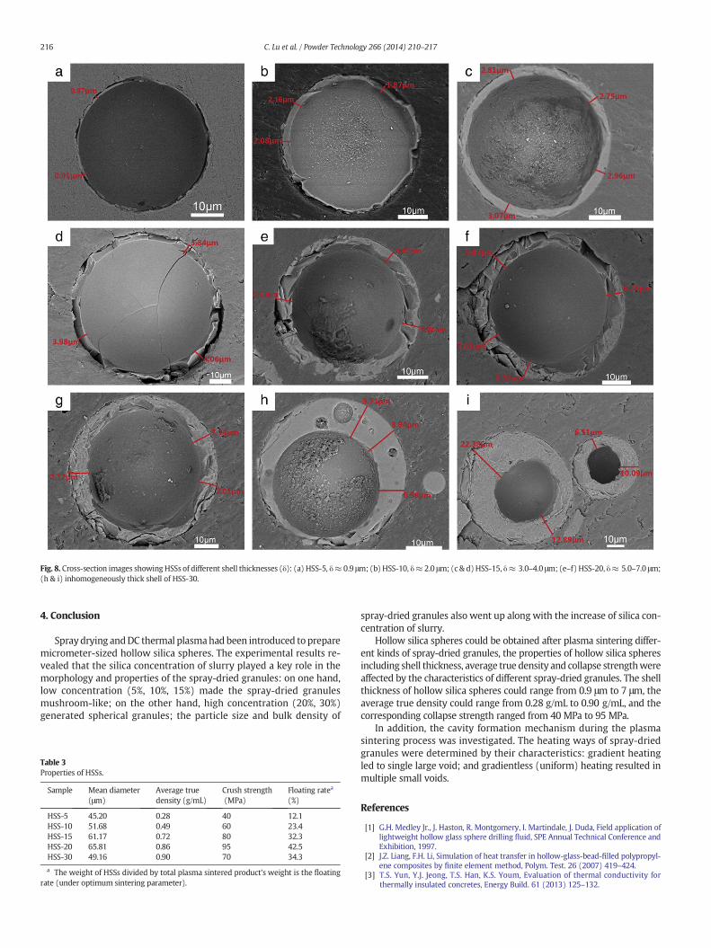
Fig. 8. Cross-section images showing HSSs of different shell thicknesses (δ): (a) HSS-5, δ≈ 0.9 μm; (b) HSS-10, δ≈ 2.0 μm; (c & d)HSS-15, δ≈ 3.0–4.0 μm; (e–f) HSS-20, δ≈ 5.0–7.0 μm;(h & i) inhomogeneously thick shell of HSS-30.
216 C. Lu et al. / Powder Technology 266 (2014) 210–217
4. Conclusion
Spraydrying andDC thermal plasmahad been introduced to preparemicrometer-sized hollow silica spheres. The experimental results re-vealed that the silica concentration of slurry played a key role in themorphology and properties of the spray-dried granules: on one hand,low concentration (5%, 10%, 15%) made the spray-dried granulesmushroom-like; on the other hand, high concentration (20%, 30%)generated spherical granules; the particle size and bulk density of
Table 3Properties of HSSs.
Sample Mean diameter(μm)
Average truedensity (g/mL)
Crush strength(MPa)
Floating ratea
(%)
HSS-5 45.20 0.28 40 12.1HSS-10 51.68 0.49 60 23.4HSS-15 61.17 0.72 80 32.3HSS-20 65.81 0.86 95 42.5HSS-30 49.16 0.90 70 34.3
a The weight of HSSs divided by total plasma sintered product's weight is the floatingrate (under optimum sintering parameter).
spray-dried granules also went up along with the increase of silica con-centration of slurry.
Hollow silica spheres could be obtained after plasma sintering differ-ent kinds of spray-dried granules, the properties of hollow silica spheresincluding shell thickness, average true density and collapse strengthwereaffected by the characteristics of different spray-dried granules. The shellthickness of hollow silica spheres could range from 0.9 μm to 7 μm, theaverage true density could range from 0.28 g/mL to 0.90 g/mL, and thecorresponding collapse strength ranged from 40 MPa to 95 MPa.
In addition, the cavity formation mechanism during the plasmasintering process was investigated. The heating ways of spray-driedgranules were determined by their characteristics: gradient heatingled to single large void; and gradientless (uniform) heating resulted inmultiple small voids.
References
[1] G.H. Medley Jr., J. Haston, R. Montgomery, I. Martindale, J. Duda, Field application oflightweight hollow glass sphere drilling fluid, SPE Annual Technical Conference andExhibition, 1997.
[2] J.Z. Liang, F.H. Li, Simulation of heat transfer in hollow-glass-bead-filled polypropyl-ene composites by finite element method, Polym. Test. 26 (2007) 419–424.
[3] T.S. Yun, Y.J. Jeong, T.S. Han, K.S. Youm, Evaluation of thermal conductivity forthermally insulated concretes, Energy Build. 61 (2013) 125–132.

217C. Lu et al. / Powder Technology 266 (2014) 210–217
[4] B. Schwarz-Rohr, Scattering of sound by a hollow, hard sphere with an opening,Acta Acustica United Acustica 92 (2006) 521–529.
[5] J.Z. Liang, Mechanical properties of hollow glass bead-filled ABS composites, J.Thermoplast. Compos. Mater. 18 (2005) 407–416.
[6] J.Z. Liang, Tensile properties of hollow glass bead-filled polypropylene composites, J.Appl. Polym. Sci. 104 (2007) 1697–1701.
[7] J.K. Cochran, Ceramic hollow spheres and their applications, Curr. Opin. Solid StateMater. Sci. 3 (1998) 474–479.
[8] Y. Liao, X.Wu, H. Liu, Y. Chen, Thermal conductivity of powder silica hollow spheres,Thermochim. Acta 526 (2011) 178–184.
[9] J. Manuel, J.G. Blanco, K.L. Marquez, Field application of glass bubbles as a density-reducing agent, SPE 62899, 2000.
[10] J. Blanco, F. Ramirez, F. Mata, A. Ojeda, B. Atencio, Field application of glass bubblesas a density reducing agent in an oil base drilling fluid for marginal/low-permeability/low-pressure reservoirs, SPE Gas Technology Symposium, 2002.
[11] H. Zhang, J. Wu, L. Zhou, D. Zhang, L. Qi, Facile synthesis of monodisperse micro-spheres and gigantic hollow shells of mesoporous silica inmixedwater–ethanol sol-vents, Langmuir 23 (2006) 1107–1113.
[12] X. Cheng, S. Liu, L. Lu, X. Sui, V. Meynen, P. Cool, E.F. Vansant, J. Jiang, Fast fabricationof hollow silica spheres with thermally stable nanoporous shells, MicroporousMesoporous Mater. 98 (2007) 41–46.
[13] X.F. Wu, H.R. Lu, Z.Q. Wang, X.H. Xu, Preparation of hollow silica beads via soft tem-plate calcinating route, J. Sol-Gel Sci. Technol. 54 (2010) 147–153.
[14] F. Caruso, Hollow capsule processing through colloidal templating and self-assembly, Chem. Eur. J. 6 (2000) 413–419.
[15] M. Chen, L. Wu, S. Zhou, B. You, A method for the fabrication of monodispersehollow silica spheres, Adv. Mater. 18 (2006) 801–806.
[16] K.D. Kim, K.Y. Choi, J.W. Yang, Formation of spherical hollow silica particles from so-dium silicate solution by ultrasonic spray pyrolysis method, Colloids Surf. A 254(2005) 193–198.
[17] W.S. Cheow, S. Li, K. Hadinoto, Spray drying formulation of hollow spherical aggregatesof silica nanoparticles by experimental design, Chem. Eng. Res. Des. 88 (2010) 673–685.
[18] F.N. Longo, N.F. Bader III, M.R. Dorfman, Hollow sphere ceramic particles for abrad-able coatings: U.S, Patent 4,450,184[P], 1984. 5–22.
[19] Z. Karoly, J. Szepvogyi, Hollow alumina microspheres prepared by RF thermal plas-ma, Powder Technol. 132 (2003) 211–215.
[20] W. Lee, S. Choi, S.M. Oh, D.W. Park, Preparation of spherical hollow alumina particlesby thermal plasma, Thin Solid Films 529 (2013) 394–397.
[21] D. Sen, S. Mazumder, J.S. Melo, A. Khan, S. Bhattyacharya, S.F. D'Souza, Evaporationdriven self-assembly of a colloidal dispersion during spray drying: volume fractiondependent morphological transition, Langmuir 25 (2009) 6690–6695.
[22] F. Iskandar, L. Gradon, K. Okuyama, Control of the morphology of nanostructuredparticles prepared by the spray drying of a nanoparticle sol, J. Colloid Interface Sci.265 (2003) 296–303.
[23] H. Liang, K. Shinohara, H. Minoshima, K. Matsushima, Analysis of constant rate peri-od of spray drying of slurry, Chem. Eng. Sci. 56 (2001) 2205–2213.
[24] D.E. Walton, C.J. Mumford, The morphology of spray-dried particles: the effect ofprocess variables upon the morphology of spray-dried particles, Chem. Eng. Res.Des. 77 (1999) 442–460.
[25] Z. Károly, J. Szépvölgyi, Z. Farkas, Simultaneous calcination and spheroidization ofgibbsite powders in an RF thermal plasma, Powder Technol. 110 (2000) 169–178.
[26] G. Pravdic, M.S.J. Gani, The formation of hollow spherical ceramic oxide particles in ad.c. plasma, J. Mater. Sci. 31 (1996) 3487–3495.
[27] O.P. Solonenko, I.P. Gulyaev, A.V. Smirnov, Thermal plasma processes for productionof hollow spherical powders: theory and experiment, J. Therm. Sci. Technol. 6(2011) 219–234.
[28] M.A. Krenzke, R.M. Charles, The Elastic Buckling Strength of Spherical Glass Shells,David Taylor Model Basin, Washington DC, 1963. (No. DTMB-1759).
[29] J.H. Campbell, J.Z. Grens, J.F. Poco, Preparation and properties of hollow glass micro-spheres for use in laser fusion experiments, 1983. 65.


![Nonporous silica nanoparticles for nanomedicine application...Synthesis of size-controlled silica NPs was first reported by Stöber et al. in 1968 [19]. Monodisperse silica spheres](https://static.fdocuments.in/doc/165x107/609b60c36163736c4d72f238/nonporous-silica-nanoparticles-for-nanomedicine-application-synthesis-of-size-controlled.jpg)