LTM Administrator Guide Documentation - · PDF file1.7 Active Directory ... 2.3 The...
75
LTM Administrator Guide Documentation Release 1.6.0 Lenovo May 22, 2017
-
Upload
nguyenkien -
Category
Documents
-
view
228 -
download
0
Transcript of LTM Administrator Guide Documentation - · PDF file1.7 Active Directory ... 2.3 The...
LTM Administrator GuideDocumentation
Release 1.6.0
Lenovo
May 22, 2017

Contents
1 Virtual Appliance Installation and Setup 21.1 Download and Install VMware vSphere or VMware Player . . . . . . . . . . . . . . . . . . 21.2 Install Virtual Machine Setup on VMware . . . . . . . . . . . . . . . . . . . . . . . . . . . 21.3 Installing on XenServer® . . . . . . . . . . . . . . . . . . . . . . . . . . . . . . . . . . . 41.4 Installing on a Hyper-V® Server . . . . . . . . . . . . . . . . . . . . . . . . . . . . . . . . 41.5 First Run Configuration . . . . . . . . . . . . . . . . . . . . . . . . . . . . . . . . . . . . 51.6 Network Configuration . . . . . . . . . . . . . . . . . . . . . . . . . . . . . . . . . . . . . 51.7 Active Directory . . . . . . . . . . . . . . . . . . . . . . . . . . . . . . . . . . . . . . . . 61.8 The Main Menu . . . . . . . . . . . . . . . . . . . . . . . . . . . . . . . . . . . . . . . . 71.9 Final Configuration Steps . . . . . . . . . . . . . . . . . . . . . . . . . . . . . . . . . . . 91.10 Firewall Ports . . . . . . . . . . . . . . . . . . . . . . . . . . . . . . . . . . . . . . . . . . 91.11 Enable AMQP Support . . . . . . . . . . . . . . . . . . . . . . . . . . . . . . . . . . . . . 101.12 Check Connectivity . . . . . . . . . . . . . . . . . . . . . . . . . . . . . . . . . . . . . . 111.13 Additional Installation . . . . . . . . . . . . . . . . . . . . . . . . . . . . . . . . . . . . . 12
2 Learning Basics 132.1 Basic Terminology . . . . . . . . . . . . . . . . . . . . . . . . . . . . . . . . . . . . . . . 132.2 Accessing the Graphical Interface . . . . . . . . . . . . . . . . . . . . . . . . . . . . . . . 132.3 The Administration Page . . . . . . . . . . . . . . . . . . . . . . . . . . . . . . . . . . . . 132.4 Devices Page . . . . . . . . . . . . . . . . . . . . . . . . . . . . . . . . . . . . . . . . . . 142.5 Connections Page . . . . . . . . . . . . . . . . . . . . . . . . . . . . . . . . . . . . . . . 142.6 Profiles Page . . . . . . . . . . . . . . . . . . . . . . . . . . . . . . . . . . . . . . . . . . 142.7 Disk Images Page . . . . . . . . . . . . . . . . . . . . . . . . . . . . . . . . . . . . . . . 142.8 Device Settings Page . . . . . . . . . . . . . . . . . . . . . . . . . . . . . . . . . . . . . . 142.9 Certificates Page . . . . . . . . . . . . . . . . . . . . . . . . . . . . . . . . . . . . . . . . 152.10 Software Page . . . . . . . . . . . . . . . . . . . . . . . . . . . . . . . . . . . . . . . . . 152.11 Tasks Page . . . . . . . . . . . . . . . . . . . . . . . . . . . . . . . . . . . . . . . . . . . 152.12 Imprivata Page . . . . . . . . . . . . . . . . . . . . . . . . . . . . . . . . . . . . . . . . . 152.13 Logs Page . . . . . . . . . . . . . . . . . . . . . . . . . . . . . . . . . . . . . . . . . . . 152.14 Searches . . . . . . . . . . . . . . . . . . . . . . . . . . . . . . . . . . . . . . . . . . . . 15
3 Device Management 163.1 Action Bars . . . . . . . . . . . . . . . . . . . . . . . . . . . . . . . . . . . . . . . . . . . 16
i
3.2 Selection Tool . . . . . . . . . . . . . . . . . . . . . . . . . . . . . . . . . . . . . . . . . 163.3 Add or Remove . . . . . . . . . . . . . . . . . . . . . . . . . . . . . . . . . . . . . . . . . 173.4 Filter . . . . . . . . . . . . . . . . . . . . . . . . . . . . . . . . . . . . . . . . . . . . . . 173.5 Groups . . . . . . . . . . . . . . . . . . . . . . . . . . . . . . . . . . . . . . . . . . . . . 183.6 Export . . . . . . . . . . . . . . . . . . . . . . . . . . . . . . . . . . . . . . . . . . . . . 193.7 Device Actions . . . . . . . . . . . . . . . . . . . . . . . . . . . . . . . . . . . . . . . . . 193.8 Device Power Options . . . . . . . . . . . . . . . . . . . . . . . . . . . . . . . . . . . . . 203.9 Device Network Configuration . . . . . . . . . . . . . . . . . . . . . . . . . . . . . . . . . 213.10 Shadow . . . . . . . . . . . . . . . . . . . . . . . . . . . . . . . . . . . . . . . . . . . . . 223.11 Cloning Overview . . . . . . . . . . . . . . . . . . . . . . . . . . . . . . . . . . . . . . . 233.12 Cloning Connections . . . . . . . . . . . . . . . . . . . . . . . . . . . . . . . . . . . . . . 243.13 Connection Variable Substitution . . . . . . . . . . . . . . . . . . . . . . . . . . . . . . . 263.14 Cloning Device Settings . . . . . . . . . . . . . . . . . . . . . . . . . . . . . . . . . . . . 283.15 Disk Image Cloning . . . . . . . . . . . . . . . . . . . . . . . . . . . . . . . . . . . . . . 293.16 Profiles . . . . . . . . . . . . . . . . . . . . . . . . . . . . . . . . . . . . . . . . . . . . . 323.17 Certificates . . . . . . . . . . . . . . . . . . . . . . . . . . . . . . . . . . . . . . . . . . . 343.18 Software Packages . . . . . . . . . . . . . . . . . . . . . . . . . . . . . . . . . . . . . . . 353.19 Tasks . . . . . . . . . . . . . . . . . . . . . . . . . . . . . . . . . . . . . . . . . . . . . . 373.20 Imprivata . . . . . . . . . . . . . . . . . . . . . . . . . . . . . . . . . . . . . . . . . . . . 38
4 Appliance Settings 424.1 Server Settings . . . . . . . . . . . . . . . . . . . . . . . . . . . . . . . . . . . . . . . . . 424.2 Licenses . . . . . . . . . . . . . . . . . . . . . . . . . . . . . . . . . . . . . . . . . . . . 434.3 Products . . . . . . . . . . . . . . . . . . . . . . . . . . . . . . . . . . . . . . . . . . . . 444.4 Storage Locations . . . . . . . . . . . . . . . . . . . . . . . . . . . . . . . . . . . . . . . 444.5 Groups Settings . . . . . . . . . . . . . . . . . . . . . . . . . . . . . . . . . . . . . . . . 454.6 Database Hotcopy . . . . . . . . . . . . . . . . . . . . . . . . . . . . . . . . . . . . . . . 464.7 Restore Server . . . . . . . . . . . . . . . . . . . . . . . . . . . . . . . . . . . . . . . . . 474.8 Permissions . . . . . . . . . . . . . . . . . . . . . . . . . . . . . . . . . . . . . . . . . . . 484.9 Appliance Upgrades . . . . . . . . . . . . . . . . . . . . . . . . . . . . . . . . . . . . . . 494.10 Package Management . . . . . . . . . . . . . . . . . . . . . . . . . . . . . . . . . . . . . 494.11 Audit Trail . . . . . . . . . . . . . . . . . . . . . . . . . . . . . . . . . . . . . . . . . . . 504.12 Automatic SCEP . . . . . . . . . . . . . . . . . . . . . . . . . . . . . . . . . . . . . . . . 51
5 Terminology 535.1 General Terms . . . . . . . . . . . . . . . . . . . . . . . . . . . . . . . . . . . . . . . . . 535.2 Device Details . . . . . . . . . . . . . . . . . . . . . . . . . . . . . . . . . . . . . . . . . 545.3 Connection Details . . . . . . . . . . . . . . . . . . . . . . . . . . . . . . . . . . . . . . . 555.4 Profile Details . . . . . . . . . . . . . . . . . . . . . . . . . . . . . . . . . . . . . . . . . 665.5 Disk Image Details . . . . . . . . . . . . . . . . . . . . . . . . . . . . . . . . . . . . . . . 675.6 Device Setting Details . . . . . . . . . . . . . . . . . . . . . . . . . . . . . . . . . . . . . 685.7 Certificate Details . . . . . . . . . . . . . . . . . . . . . . . . . . . . . . . . . . . . . . . 685.8 Imprivata Details . . . . . . . . . . . . . . . . . . . . . . . . . . . . . . . . . . . . . . . . 695.9 Task Details . . . . . . . . . . . . . . . . . . . . . . . . . . . . . . . . . . . . . . . . . . 69
6 Legal 70
Index 71
ii
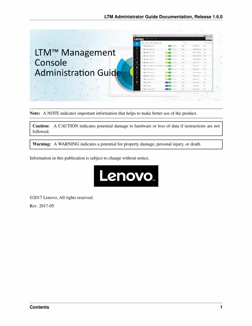
LTM Administrator Guide Documentation, Release 1.6.0
Note: A NOTE indicates important information that helps to make better use of the product.
Caution: A CAUTION indicates potential damage to hardware or loss of data if instructions are notfollowed.
Warning: A WARNING indicates a potential for property damage, personal injury, or death.
Information in this publication is subject to change without notice.
©2017 Lenovo, All rights reserved.
Rev. 2017-05
Contents 1
CHAPTER 1
Virtual Appliance Installation and Setup
This administration guide outlines how to install, setup, and run the Lenovo® Terminal Management™Platform, also known as LTM™ Management Appliance. Required components include:
1. A 64-bit host running VMware® Workstation Player™, VMware® ESXi™, Citrix® XenServer®, orMicrosoft® Hyper-V®.
2. Access to DNS and DHCP server configuration.
The instructions below are for users who wish to use an alternate method to the OVF deployment that isavailable.
1.1 Download and Install VMware vSphere or VMware Player
Download and install the VMware vSphere® Client or VMware® Workstation Player™ on a dedicatedsystem. If assistance is needed to install this software correctly, please visit http://vmware.com.
1.2 Install Virtual Machine Setup on VMware
1.2.1 VMware ESX v5.0+
To start a virtual machine of the Management Appliance on VMware® ESX® versions 5.0 and up:
1. Launch VMware® vCenter™ Converter™. Have the Management Appliance files extracted so theyare ready for installation. Click on Convert Machine to begin the installation process.
2. In Source System, select VMware Workstation Player or other VMware virtual machine.
3. Click Browse and locate the extracted Management Appliance files and select the appropriate .vmxfile and click Next.
4. In Destination System, select the VMware Infrastructure virtual machine option and enter theVMware Infrastructure server credentials for an account that has administrator access to the ESX orvSphere server on which the Management Appliance is to be installed and click Next.
5. In Destination Virtual Machine, enter a name for the new Virtual Machine and select a destinationfor the Management Appliance on the ESX or vSphere server, then click Next.
2
LTM Administrator Guide Documentation, Release 1.6.0
6. In Destination Location, select an appropriate datastore where the Management Appliance will bestored. The appliance will consume approximately 11GB of hard disk space.
7. In Options, configurations may either be adjusted or left at default settings. When finished, clickNext.
8. In Summary, verify that all the settings are correct and click Finish.
Note: Make sure that this is a newly downloaded appliance and not one that has been opened andrun within VMware Workstation Player.
1.2.2 Installing without VMware vCenter Converter
To start a virtual machine without the use of vCenter Converter:
1. Extract the Management Appliance files. Open the VMware Infrastructure Client and connect to theESX or vSphere server.
2. Browse the datastore where the Management Appliance will be hosted in. Once in the DatastoreBrowser, select the option to Upload Folder.
3. Browse to the location of the extracted Management Appliance folder and select it for upload. Whenthe Management Appliance has finished uploading, return to the VMware Infrastructure landing page.
4. Create a new Virtual Machine and select the hosting server that will run the Management Appliance.
5. At the Configuration screen, select the Custom option to allow for a customized setup process andclick Next. In Name and Location, enter a name for the new Virtual Machine and select a destinationfor the Management Appliance on the ESX or vSphere server, then click Next.
6. In Storage, select the datastore where the Management Appliance will be stored. This should be thesame datastore that was chosen in Step 2. For the Virtual Machine Version, select the version bestsuited for the server.
7. In the Guest Operating System screen, select the OS type that will be used. In most cases, the GuestOS for the Management Appliance will be Linux, with the Ubuntu Linux (64-bit) version.
8. For the CPU, Memory, and Network screens, the default options will be acceptable in most cases.However, these can all be adjusted based on what is desired or specified. In SCSI Controller, selectthe LSI Logic Parallel option.
9. In the Select a Disk screen, use the “Use an existing virtual disk” option. Choosing this option willcreate a new Select Existing Disk screen. From there, locate the folder that as uploaded from theDatastore Browser in Step 2.
10. In Advanced Options, select a virtual device node and make any necessary adjustments. In mostcases, these options can be left to their default settings.
11. Review all settings in the Ready to Complete screen before finalizing the virtual machine. If every-thing looks acceptable, click Finish. The appliance can now be booted up to complete the installationprocess.
1.2. Install Virtual Machine Setup on VMware 3
LTM Administrator Guide Documentation, Release 1.6.0
1.2.3 VMware Workstation Player
To start a virtual machine on VMware Workstation Player:
1. Launch VMware Workstation Player and click Open.
2. Open the correct .vmx file located in the LTM folder.
3. The virtual appliance will immediately begin booting.
1.3 Installing on XenServer®
If the .xva file for the Management Appliance is available, follow these steps to set up on XenServer®:
1. Open the XenCenter® Client.
2. The server should already be listed from the initial installation of XenCenter. Select the desired serverfrom the inventory on the left hand side.
3. In XenCenter, access File, then Import and browse to the location of the XVA file for LTM. ClickNext.
4. Select the server where the Management Appliance will be placed on. Click Next.
5. Select which storage repository to use from the list and click Import.
6. Choose the desired networking option and click Next.
7. Click Finish to complete the process.
1.4 Installing on a Hyper-V® Server
If the .vhd file for the Management Appliance is available, follow these steps to set up on Hyper-V® server:
1. Open the Hyper-V® Manager.
2. If necessary, right click on Hyper-V® Manager in the left hand column and select Connect toServer. . . , then click Ok.
3. Click on Action, then New, followed by Virtual Machine on the right hand side. Click Next.
4. Name the management server. Click on Browse and navigate to the location where the files will bestored. Click Next.
5. If applicable, select the generation of the virtual machine. Select Generation 1 and click Next tocontinue.
6. Designate the amount of RAM (1024MB minimum) that will be allocated to the Hyper-V® server.Click on Next.
7. Select the connection to use from the dropdown menu and click Next.
8. Click on Use an existing virtual hard disk and then click Browse. Navigate to the .vhd file and clickNext.
4 Chapter 1. Virtual Appliance Installation and Setup
LTM Administrator Guide Documentation, Release 1.6.0
9. Confirm that the information presented is accurate. Click Previous to make any adjustments, orFinish if everything is correct.
1.5 First Run Configuration
1.5.1 Password and Time Zone Configurations
1. Turn on the Virtual Machine.
2. After the boot up process is complete, the Setting Password page is displayed.
3. Enter a password for the default bwadmin account. This password is required to initially log in tomanagement platform.
Note: There is no minimum character limit required when entering a new password and thepassword is case sensitive. It is recommended that the administrator create a password of atleast six characters, using a combination of upper and lowercase alphanumeric characters.
4. Once a password has been entered, use the arrow keys to navigate to the OK button and press tocontinue. A prompt will appear, asking for the password to be entered a second time. Press the OKbutton again.
5. A list of locations is displayed in the Change Time Zone page. Select the appropriate time zone andpress .
1.6 Network Configuration
After the password and time zone have been configured, the next step of the initial setup wizard is todetermine the IP configuration.
1. Enter a static IP address for this instance of the management platform, and press OK.
2. On the next page will be a prompt to enter the subnet mask. Typically, this will be a class C subnetmask (255.255.255.0). Once the subnet mask has been filled in, press OK.
3. On the Configure Gateway page, enter the gateway IP address and press OK.
4. On the Configure DNS Nameservers page, enter the IP addresses of the nameservers, using a space inbetween each address. This will allow the appliance to resolve domain names. Once the IP addresseshave been entered, press OK.
5. In the Configure DNS Search Domains page, enter the DNS search path for the domain. If there aremultiple domains, separate the entries with a space. Once all domains have been entered, press OK.
6. After selecting OK, the network interface will restart and the Main Menu will display.
1.5. First Run Configuration 5
LTM Administrator Guide Documentation, Release 1.6.0
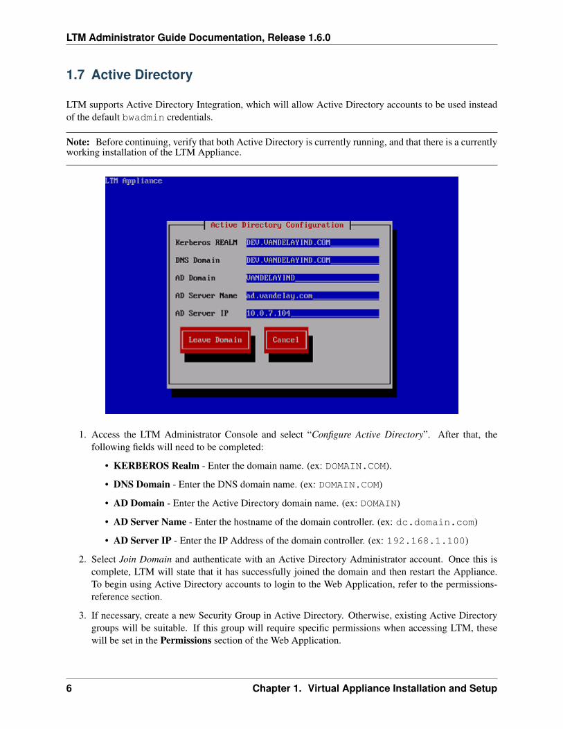
1.7 Active Directory
LTM supports Active Directory Integration, which will allow Active Directory accounts to be used insteadof the default bwadmin credentials.
Note: Before continuing, verify that both Active Directory is currently running, and that there is a currentlyworking installation of the LTM Appliance.
1. Access the LTM Administrator Console and select “Configure Active Directory”. After that, thefollowing fields will need to be completed:
• KERBEROS Realm - Enter the domain name. (ex: DOMAIN.COM).
• DNS Domain - Enter the DNS domain name. (ex: DOMAIN.COM)
• AD Domain - Enter the Active Directory domain name. (ex: DOMAIN)
• AD Server Name - Enter the hostname of the domain controller. (ex: dc.domain.com)
• AD Server IP - Enter the IP Address of the domain controller. (ex: 192.168.1.100)
2. Select Join Domain and authenticate with an Active Directory Administrator account. Once this iscomplete, LTM will state that it has successfully joined the domain and then restart the Appliance.To begin using Active Directory accounts to login to the Web Application, refer to the permissions-reference section.
3. If necessary, create a new Security Group in Active Directory. Otherwise, existing Active Directorygroups will be suitable. If this group will require specific permissions when accessing LTM, thesewill be set in the Permissions section of the Web Application.
6 Chapter 1. Virtual Appliance Installation and Setup
LTM Administrator Guide Documentation, Release 1.6.0
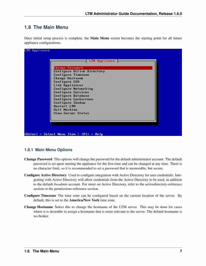
1.8 The Main Menu
Once initial setup process is complete, the Main Menu screen becomes the starting point for all futureappliance configurations.
1.8.1 Main Menu Options
Change Password This options will change the password for the default administrator account. The defaultpassword is set upon starting the appliance for the first time and can be changed at any time. There isno character limit, so it is recommended to set a password that is memorable, but secure.
Configure Active Directory Used to configure integration with Active Directory for user credentials. Inte-grating with Active Directory will allow credentials from the Active Directory to be used, in additionto the default bwadmin account. For more on Active Directory, refer to the activedirectory-referencesection or the permissions-reference section.
Configure Timezone The time zone can be configured based on the current location of the server. Bydefault, this is set to the America/New York time zone.
Change Hostname Select this to change the hostname of the LTM server. This may be done for caseswhere it is desirable to assign a hostname that is more relevant to the server. The default hostname isws-broker.
1.8. The Main Menu 7
LTM Administrator Guide Documentation, Release 1.6.0
Link Appliances This option allows two Management Appliances to link together, if they share a database.A database will need to be configured beforehand. This option may also be ideal for administratorswho wish to use the AMQP protocol with their setup.
Configure SSH Select this to configure the built-in SSH server. Enabling SSH will allow remote access tothe command line of the management server.
Configure Networking The network options of the Management Appliance can be configured. The fol-lowing settings can be adjusted:
Configure Network Interfaces This option modifies the static network settings.
Configure Routes This option modifies the local routing table.
Configure Database The management server can be configured to use external PostgreSQL, MSSQL, andMySQL databases. By default, it uses it’s own internal MySQL Database. This database can beconfigured at any time. This is required for linking appliances together.
Configure Lockscreen The timeout period for the lockscreen can be adjusted, as well as disabled. Disabledlockscreens can be re-enabled at any time.
Configure Shadow This configures the way the Management Server handles Shadow sessions. By default,the Management Server will allow ten Shadow sessions running at one time among all active usersand sessions. Any other attempts to Shadow a device will be rejected until one of the other tensessions has concluded. The number of allowed Shadow sessions can be adjusted to accommodate forcurrent network speed. There are also fields to tell the Management Appliance what ports are openfor Shadow to use. For more information on using Shadow, see shadow-reference.
Restart LTM This will restart the LTM server. This option is necessary for cases where the ManagementServer has had settings adjusted.
Halt Machine This will power off the Management Appliance. This option is necessary for cases wherethe Management Server may be replaced.
View Server Status This will display the current status of the server. Here, Administrators will be able toview the status of all connected servers, as well as the database connectivity status. This status screenwill also inform the Administrator if the Management Appliance is currently joined to an ActiveDirectory, and if there has been a link created with another appliance. Miscellaneous informationabout the current appliance version is also displayed for support purposes.
8 Chapter 1. Virtual Appliance Installation and Setup
LTM Administrator Guide Documentation, Release 1.6.0
1.9 Final Configuration Steps
1.9.1 DNS Configuration
By default, devices running LeTOS™ will attempt to resolve two types of DNS records:
• A top-level, Host(A) Record named ws-broker.
• An SRV record named _mgr._tcp.
It is recommended for simple deployments that the administrator use the first approach, and create a singleDNS entry for ws-broker, assigned to the static IP configured for the Management Appliance. For example:
• ws-broker.myXyzConsulting.com
• ws-broker.HiTechSolutions.net
• ws-broker.development.org
In more complicated deployments where high availability is required it is recommended that an SRV recordbe used instead. Assigning a number of IP addresses for multiple instances of the Management Applianceallows for management reliability in failover scenarios.
1.10 Firewall Ports
1.10.1 What Ports need to be Open for Functionality?
• Port 80: Used by the Management Server. HTTP – Standard web port for the appliance Web UI.
• Port 443: Used by the Management Server. HTTPS – Secure (SSL) communication over http protocol
• Port 50000: Used by the Management Server, Hosts, and Devices. Used by SOAP. This port needsto be open on ALL devices within the management environment
• Port 5671: Used by the Management Server, Hosts, and Devices. Used by AMQP. This port needs tobe open on ALL devices within the management environment
1.9. Final Configuration Steps 9
LTM Administrator Guide Documentation, Release 1.6.0
1.11 Enable AMQP Support
It is possible to switch to the AMQP protocol on supported devices. This is an option for users who wish touse NAT transversal. To enable AMQP support:
1. If there is a firewall on the network, ensure that the following ports are open:
• Port 80: HTTP - This is a standard web port for the Management Appliance WebUI.
• Port 443: HTTPS - This is a secure (SSL) communication over an HTTP protocol.
• Port 50000: This is used by SOAP. This port needs to be open on the Management Serverenvironment (Bidirectional Connection Required) and all devices need to be able to reach it.
• Port 5671: This is used by AMQP. This port also needs to be open on the Management Serverenvironment.
2. Create an ftp:// or http:// server that can be accessed by the relevant thin clients. This serverwill be used to host the script that will enable AMQP support on devices. The script can be accessedfrom here (http://downloads.devonit.com/SalesEng/amqp/enable-amqp) for devices running LeTOS,and here (http://downloads.devonit.com/SalesEng/amqp/enable-amqp.cmd) for devices running Win-dows Embedded operating systems. If it is not possible to create a host server, then the links providedmay also be used as a host.
3. Open the Management Appliance WebUI by browsing to the IP address or hostname of the appliancewithin any web browser. Log in using Administrator credentials, then open the Devices inventory.
4. Select one or more of the devices that will use the AMQP protocol. Click on the Device Actions button(the Gear icon) and select the Execute a File option. Insert the ftp:// or http:// location thatis hosting the AMQP script and click on the check button to apply the script to the device(s).
To verify that a device is set to use the AMQP protocol, click on the device’s information icon (the i buttonlocated next to the device in the device inventory). The Protocol of the device will be listed.
Note: Once AMQP support is enabled, port 50000 is no longer required to be open.
10 Chapter 1. Virtual Appliance Installation and Setup
LTM Administrator Guide Documentation, Release 1.6.0
1.12 Check Connectivity
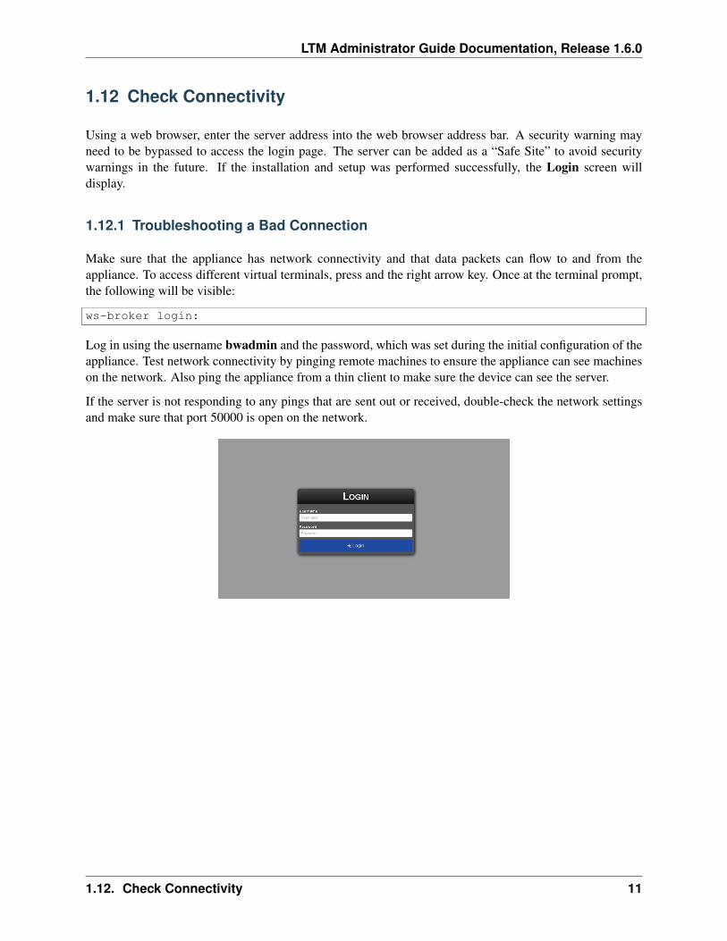
Using a web browser, enter the server address into the web browser address bar. A security warning mayneed to be bypassed to access the login page. The server can be added as a “Safe Site” to avoid securitywarnings in the future. If the installation and setup was performed successfully, the Login screen willdisplay.
1.12.1 Troubleshooting a Bad Connection
Make sure that the appliance has network connectivity and that data packets can flow to and from theappliance. To access different virtual terminals, press and the right arrow key. Once at the terminal prompt,the following will be visible:
ws-broker login:
Log in using the username bwadmin and the password, which was set during the initial configuration of theappliance. Test network connectivity by pinging remote machines to ensure the appliance can see machineson the network. Also ping the appliance from a thin client to make sure the device can see the server.
If the server is not responding to any pings that are sent out or received, double-check the network settingsand make sure that port 50000 is open on the network.
1.12. Check Connectivity 11
LTM Administrator Guide Documentation, Release 1.6.0
1.13 Additional Installation
1.13.1 Steps for Advanced Configurations
Please read the next sections only if more than one Virtual Appliance is being deployed in the same envi-ronment. If this does not apply, skip to basics-reference.
1.13.2 Configure Appliance to Use an External Database
The appliance may be connected to an external database, if desired. To configure the appliance to use anexternal database:
1. Select Configure Database from the Main Menu.
2. Choose the Select and Configure a Different Database option.
3. Choose the desired database type.
4. Enter the appropriate values for the IP address, port, username, password, and database fields thatcorrelate to the external database. When finished, select Save.
5. Select Restart LTM from the Main Menu to activate the database connection.
12 Chapter 1. Virtual Appliance Installation and Setup
CHAPTER 2
Learning Basics
2.1 Basic Terminology
The following terms are used throughout this document.
• Device - This is the physical thin client to which the monitor, keyboard and mouse are attached.
• Session - This is a network connection between a thin client and a host, with the display and USBcomponents connected.
• Cloning - This is a process of copying the profiles, settings, or images from one device in order tomake them available for application to other devices.
2.2 Accessing the Graphical Interface
1. Using a web browser, type the server address that was assigned to the Management Appliance intothe address bar.
Note: An untrusted connection warning may appear within the browser. This will need to be by-passed, and the Management server will need to be added as an exception.
2. Enter a username and password. This login can be the Administrator credentials that were set upduring installation, or another set of credentials based on Active Directory accounts, if established.Click on the Login button. If properly configured, and DNS settings are correct, the AdministrationPage will display.
2.3 The Administration Page
The Administration Page is divided into two main sections. The left-hand side displays the navigation barwith the various pages the administrator can navigate to. The central area of the page is dedicated to theinventory or configuration table depending on which tab is selected. The different administration pages arebriefly described below. For further instruction on each page, see the devices-reference chapter.
13
LTM Administrator Guide Documentation, Release 1.6.0
2.4 Devices Page
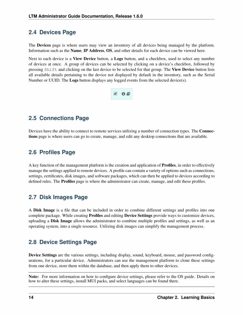
The Devices page is where users may view an inventory of all devices being managed by the platform.Information such as the Name, IP Address, OS, and other details for each device can be viewed here.
Next to each device is a View Device button, a Logs button, and a checkbox, used to select any numberof devices at once. A group of devices can be selected by clicking on a device’s checkbox, followed bypressing Shift and clicking on the last device to be selected for that group. The View Device button listsall available details pertaining to the device not displayed by default in the inventory, such as the SerialNumber or UUID. The Logs button displays any logged events from the selected device(s).
2.5 Connections Page
Devices have the ability to connect to remote services utilizing a number of connection types. The Connec-tions page is where users can go to create, manage, and edit any desktop connections that are available.
2.6 Profiles Page
A key function of the management platform is the creation and application of Profiles, in order to effectivelymanage the settings applied to remote devices. A profile can contain a variety of options such as connections,settings, certificates, disk images, and software packages, which can then be applied to devices according todefined rules. The Profiles page is where the administrator can create, manage, and edit these profiles.
2.7 Disk Images Page
A Disk Image is a file that can be included in order to combine different settings and profiles into onecomplete package. While creating Profiles and editing Device Settings provide ways to customize devices,uploading a Disk Image allows the administrator to combine multiple profiles and settings, as well as anoperating system, into a single resource. Utilizing disk images can simplify the management process.
2.8 Device Settings Page
Device Settings are the various settings, including display, sound, keyboard, mouse, and password config-urations, for a particular device. Administrators can use the management platform to clone these settingsfrom one device, store them within the database, and then apply them to other devices.
Note: For more information on how to configure device settings, please refer to the OS guide. Details onhow to alter these settings, install MUI packs, and select languages can be found there.
14 Chapter 2. Learning Basics
LTM Administrator Guide Documentation, Release 1.6.0
2.9 Certificates Page
Certificates can be added into the management platform and seen in the Certificates page. These certificatescan then be pushed down to devices through the main inventory page.
2.10 Software Page
Software packages allow administrators to incrementally patch existing devices with updates or new ver-sions of existing software. New packages may be released periodically for general use, or custom packagescan be created as required by users. This table inventories the currently available packages that have beenincluded by an administrator.
2.11 Tasks Page
The Tasks page can be used to monitor the progression status of Device Actions that were scheduled fordeferred execution. Tasks that are currently active can also have their schedules revised here.
2.12 Imprivata Page
Imprivata configurations allow administrators to remotely push Imprivata OneSign settings onto supporteddevices. The Imprivata agent must be installed on the device. A certificate may be required.
2.13 Logs Page
The Logs page can be used to monitor and view activity on the management platform, as well as changesmade to devices themselves.
2.14 Searches
The Search bar, located on the upper right-hand side of each inventory table, allows users to easily searchthat table for specific information. A search scans all possible fields in each table, so it is possible to narrowthe visible items based on specified criteria. Finding devices that share a common IP address, have the samemodel type, or use the same OS are a few of the many uses of this feature.
For example, if an administrator has to perform an update on all devices running LeTOS, typing “LeTOS”into the search field displays only those devices in the inventory table. The administrator can then performupdates with a more focused view of the devices being managed.
A new feature of the Management Appliance, Groups, supports usage as a search term. Click on the grouptag of a device, or enter “group:”, and all devices that have been assigned to that group will display in theinventory table. As information is entered into the Search field, the inventory table will automatically updateand display the items that match the search criteria.
2.9. Certificates Page 15
CHAPTER 3
Device Management
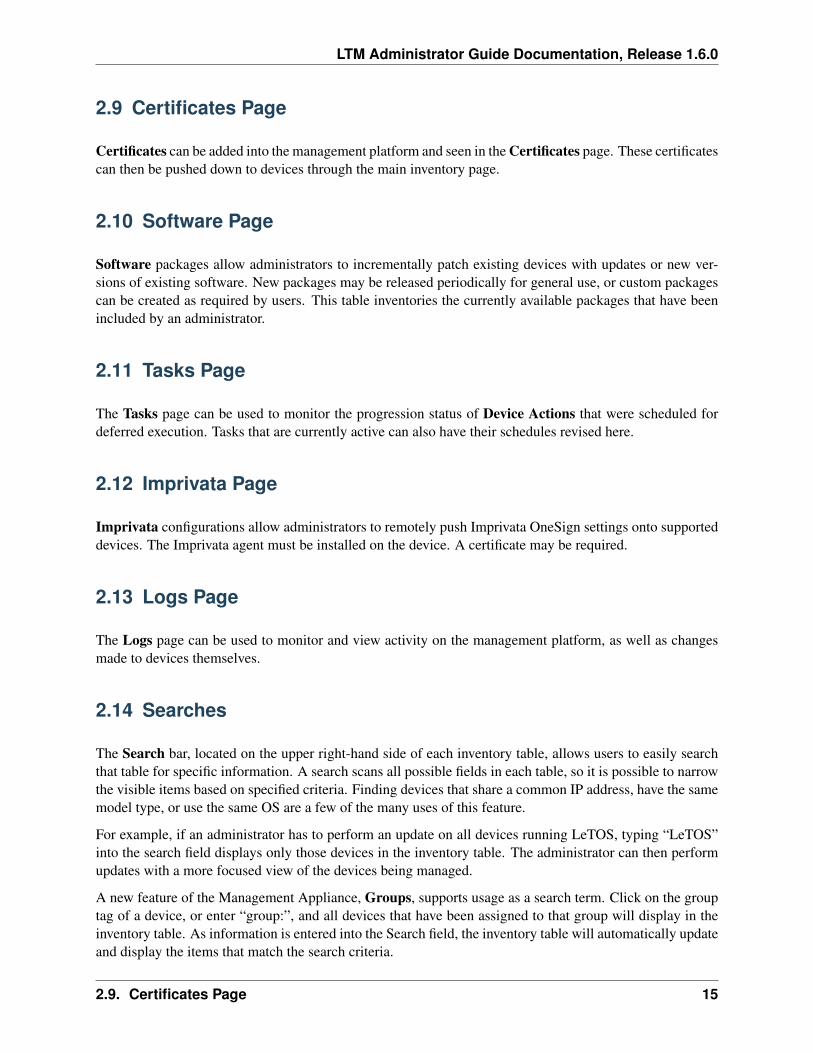
3.1 Action Bars
At the top of each inventory table are a series of icons that allow administrators to perform various tasks.The available options differ from table to table.
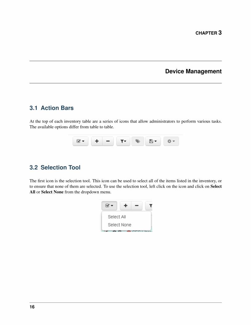
3.2 Selection Tool
The first icon is the selection tool. This icon can be used to select all of the items listed in the inventory, orto ensure that none of them are selected. To use the selection tool, left click on the icon and click on SelectAll or Select None from the dropdown menu.
16
LTM Administrator Guide Documentation, Release 1.6.0
3.3 Add or Remove
The Add and Remove icons perform different tasks depending on which page is open. When used on theDevices tab, for instance, these icons will allow the administrator to either add a new device to the manageddevices list by entering an IP address, or to remove selected devices from the list. On the other pages, theseicons are used to either create new entries (like profiles or disk images), or to remove entries.
3.4 Filter
Only available in the Devices table, the Filter button offers two unique features. The Connected settingwill organize devices based on connectivity, starting with devices that the network can reach. SelectingConnected again will instead filter unreachable devices to the top of the list.
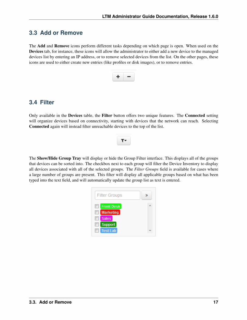
The Show/Hide Group Tray will display or hide the Group Filter interface. This displays all of the groupsthat devices can be sorted into. The checkbox next to each group will filter the Device Inventory to displayall devices associated with all of the selected groups. The Filter Groups field is available for cases wherea large number of groups are present. This filter will display all applicable groups based on what has beentyped into the text field, and will automatically update the group list as text is entered.
3.3. Add or Remove 17
LTM Administrator Guide Documentation, Release 1.6.0
3.5 Groups
Administrators may create Groups in order to organize the devices displayed in the Devices page. Byselecting a device and clicking on this button, administrators may assign a device to one or multiple groupsby typing in the name of the group they have previously created. Groups can also be automatically appliedto devices that meet the criteria that the Group is set to apply for.
If necessary, clicking on the group tag, located next to the name of a device, will have the managementserver search through the device inventory based on Groups. This will display all devices that fall into thatgroup. Devices that do not apply to a group are Unassigned.
3.5.1 Applying or Removing a Group
Once a group has been added to the Groups inventory list, it can then be applied to devices in the Devicesinventory. To apply a group to a device:
1. From the Devices inventory table, select the device or devices to be added to a group.
2. Click on the Groups button in the Actions Bar at the top of the page. This will open the Groupsdropdown menu.
3. Begin typing the name of the group in the Groups field. A dropdown menu will populate itself withthe available group names as it is typed. Multiple groups may be applied by using this method.
4. If needed, groups can also be removed from this field by clicking on the X next to the group name.This is useful for cases in which a group that is not meant to be applied accidentally gets added to thelist.
5. Once a device has the desired groups listed in the Groups field, click on the checkmark at the upperright hand corner of the Groups menu to apply the changes.
If a group is being applied based on Group Auto-Membership details, then existing devices will automat-ically update to include themselves as part of the group, and newly-added devices will be included in thegroup upon their first heartbeat to the server. If a group’s membership is changed, devices will automaticallyupdate if they meet the requirements to join the group. Devices that no longer meet the group’s membershiprequirements are automatically removed from the group.
18 Chapter 3. Device Management
LTM Administrator Guide Documentation, Release 1.6.0
3.6 Export
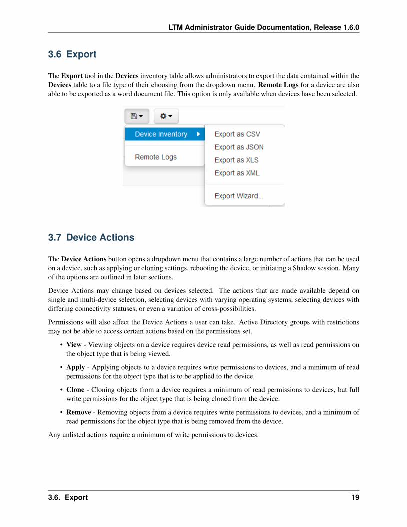
The Export tool in the Devices inventory table allows administrators to export the data contained within theDevices table to a file type of their choosing from the dropdown menu. Remote Logs for a device are alsoable to be exported as a word document file. This option is only available when devices have been selected.
3.7 Device Actions
The Device Actions button opens a dropdown menu that contains a large number of actions that can be usedon a device, such as applying or cloning settings, rebooting the device, or initiating a Shadow session. Manyof the options are outlined in later sections.
Device Actions may change based on devices selected. The actions that are made available depend onsingle and multi-device selection, selecting devices with varying operating systems, selecting devices withdiffering connectivity statuses, or even a variation of cross-possibilities.
Permissions will also affect the Device Actions a user can take. Active Directory groups with restrictionsmay not be able to access certain actions based on the permissions set.
• View - Viewing objects on a device requires device read permissions, as well as read permissions onthe object type that is being viewed.
• Apply - Applying objects to a device requires write permissions to devices, and a minimum of readpermissions for the object type that is to be applied to the device.
• Clone - Cloning objects from a device requires a minimum of read permissions to devices, but fullwrite permissions for the object type that is being cloned from the device.
• Remove - Removing objects from a device requires write permissions to devices, and a minimum ofread permissions for the object type that is being removed from the device.
Any unlisted actions require a minimum of write permissions to devices.
3.6. Export 19
LTM Administrator Guide Documentation, Release 1.6.0
3.8 Device Power Options
Administrators are able to remotely power off and power on one or more thin clients that are managed bythe Appliance. It is even possible to set a schedule so that managed devices are turned on, shut down, orrestarted at the same time every day.
3.8.1 Reboot Device
This option will have all selected devices immediately reboot, or at a set time and date. Devices mustbe powered on, connected to the network, and associated with the Management Server when this task isdistributed.
When to Run Administrators may choose to have the devices reboot immediately, or a schedule may be setso that the devices will always reboot at the same time for multiple instances. For more informationon scheduling tasks, refer to the Tasks section.
3.8.2 Power Off Device
This option will have all selected devices shut down immediately, or at a set time and date. Devices mustbe powered on, connected to the network, and associated with the Management Server when this task isdistributed.
When to Run Administrators may choose to have the devices shut down immediately, or a schedule maybe set so that the devices will always shut down at the same time for multiple instances. For moreinformation on scheduling tasks, refer to the Tasks section.
3.8.3 Wake-On-LAN
This option will have all selected devices power on immediately, or at a set time and date. Devices mustbe powered off, connected to the network, and associated with the Management Server when this task isdistributed. A Network Administrator may need to be consulted to get the information required.
Note: Wake-On-LAN has the ability to work across subnets. This requires the router to be configured toforward broadcast packets.
Port to use for wakeup signal The port that will be used for a successful wake-up. This may need to beadjusted, depending on network settings.
Subnet Mask/CIDR Length The subnet mask for the network. This is mandatory for a successful wake-up.
Subnet IP The subnet of the network. This is optional.
When to Run Administrators may choose to have the devices power on immediately, or a schedule maybe set so that the devices will always power on at the same time for multiple instances. For moreinformation on scheduling tasks, refer to the Tasks section.
20 Chapter 3. Device Management
LTM Administrator Guide Documentation, Release 1.6.0
3.9 Device Network Configuration
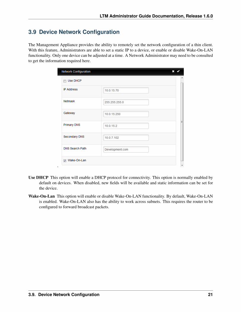
The Management Appliance provides the ability to remotely set the network configuration of a thin client.With this feature, Administrators are able to set a static IP to a device, or enable or disable Wake-On-LANfunctionality. Only one device can be adjusted at a time. A Network Administrator may need to be consultedto get the information required here.
Use DHCP This option will enable a DHCP protocol for connectivity. This option is normally enabled bydefault on devices. When disabled, new fields will be available and static information can be set forthe device.
Wake-On-Lan This option will enable or disable Wake-On-LAN functionality. By default, Wake-On-LANis enabled. Wake-On-LAN also has the ability to work across subnets. This requires the router to beconfigured to forward broadcast packets.
3.9. Device Network Configuration 21
LTM Administrator Guide Documentation, Release 1.6.0
3.10 Shadow
Administrators have the option to Shadow thin clients. With this feature, any Administrator or User accountwith approved permissions can remotely shadow a device, allowing interaction with the host unit that isbeing shadowed.
Before Shadowing can be permitted, the following settings will need to be established within the Manage-ment Appliance:
• Number of Sessions: The number of shadowing sessions that the server allow at one time. This canbe adjusted based on the network.
• Initial Client Port: The client port opened for Shadow.
• Initial Server Port The server port opened for Shadow.
Furthermore, the following ports will need to be opened in order to successfully Shadow a device:
• Ports 5500-5509: This needs to be opened to allow device-to-server communication.
• Ports 5999-6008: This needs to be opened to allow web-to-server communication.
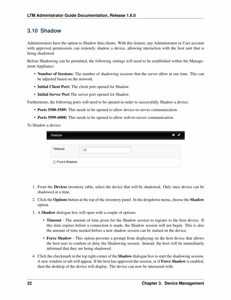
To Shadow a device:
1. From the Devices inventory table, select the device that will be shadowed. Only once device can beshadowed at a time.
2. Click the Options button at the top of the inventory panel. In the dropdown menu, choose the Shadowoption.
3. A Shadow dialogue box will open with a couple of options:
• Timeout - The amount of time given for the Shadow session to register to the host device. Ifthis time expires before a connection is made, the Shadow session will not begin. This is alsothe amount of time needed before a new shadow session can be started on the device.
• Force Shadow - This option prevents a prompt from displaying on the host device that allowsthe host user to confirm or deny the Shadowing session. Instead, the host will be immediatelyinformed that they are being shadowed.
4. Click the checkmark in the top right corner of the Shadow dialogue box to start the shadowing session.A new window or tab will appear. If the host has approved the session, or if Force Shadow is enabled,then the desktop of the device will display. The device can now be interacted with.
22 Chapter 3. Device Management
LTM Administrator Guide Documentation, Release 1.6.0
3.11 Cloning Overview
The Management Appliance is able to clone the following types:
• Connections - Devices have the ability to connect to remote servers utilizing various types of pro-tocols. The RDP® protocol is used to connect to Microsoft® Terminal Servers. The ICA® andXenAppView® protocols are used to establish connections to Citrix® servers. The VMware® Hori-zon View™ protocol allows a user to connect to a VMware Horizon View Server. Administratorsmay use the Management Appliance to clone these types of connections from one device, store themwithin their connections database, and then apply them to other devices.
• Device Settings - Device settings are the permissions, appearance, display, input, persistence, sound,printer, and time configurations for that particular device. Administrators may use the ManagementAppliance to clone these settings from one device, store them within the device settings database, andthen apply them to other devices.
• Profiles - Profiles are a way to combine multiple choices from both the Device Settings and Connec-tions configurations to create an arrangement of options tailored to the needs of the user. Administra-tors may use the Management Appliance to clone specific profiles to be applied to whichever devicesrequire these combined settings.
• Disk Images - The fourth cloning option is the ability to clone the entire disk image of a device.A disk image includes everything that is stored on the DOM on that device, including the operatingsystem itself. This does not include BIOS settings that have been saved elsewhere. Disk image clonesare inventoried and managed by name within the disk images database, but are physically stored onan nfs://, cifs://, http://, https://, or ftp:// server on the local area network.
• Imprivata - The Imprivata configurations set on a device may be cloned. This clone contains thebootstrap type, server address, default domain (if set), and other options. Administrators may usethe Management Appliance to clone these settings from one device, store them within the Imprivatadatabase, and then apply them to other devices that have the Imprivata agent installed.
When a clone is created, it will be included in its respective inventory table within the Management Appli-ance. If more than one item of the same type is cloned with the same name, the Management Appliance willinclude increments to the names as the clones are created.
3.11. Cloning Overview 23
LTM Administrator Guide Documentation, Release 1.6.0
3.12 Cloning Connections
Administrators are able to clone individual connections from a thin client and save them in the ManagementAppliance database. Administrators can easily create a desktop connection on a device and then propagateit to all of their other devices via a profile. All connections can be cloned, and the most common are listedbelow:
• RDP - One or more .rdp configuration files used for connecting to Microsoft® Terminal Servers.
• ICA - One or more .ica configuration files used for connecting to Citrix servers.
• XenAppView - Another option for accessing Citrix servers.
• VMware - The connection settings and configurations for the Horizon View client.
• Firefox® or Internet Explorer® - The local web browser and its starting URL.
• AnyConnect® VPN - Establishes a VPN connection.
• NX - Allows connectivity to a NoMachines session.
• X11 - The settings and configurations for an X11 server or application.
3.12.1 How to Clone Connections
1. From the table of inventoried devices, select a device to clone connections from and then click on theOptions button at the top of the inventory table.
2. In the dropdown menu, go to Clone and click on Connections.
3. A Clone Connections dialogue box will open with a field entitled Connections.
4. Click on the Connections field to view a dropdown list of the connections currently available forcloning from that device. Select one or several of the connections listed.
5. Click the checkmark in the top right corner of the Clone Connections dialogue box to create theclone.
6. The Connections tab will display the recently cloned connection entries in the inventory table.
24 Chapter 3. Device Management
LTM Administrator Guide Documentation, Release 1.6.0
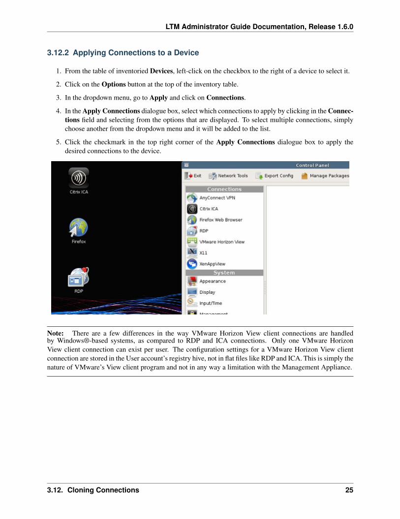
3.12.2 Applying Connections to a Device
1. From the table of inventoried Devices, left-click on the checkbox to the right of a device to select it.
2. Click on the Options button at the top of the inventory table.
3. In the dropdown menu, go to Apply and click on Connections.
4. In the Apply Connections dialogue box, select which connections to apply by clicking in the Connec-tions field and selecting from the options that are displayed. To select multiple connections, simplychoose another from the dropdown menu and it will be added to the list.
5. Click the checkmark in the top right corner of the Apply Connections dialogue box to apply thedesired connections to the device.
Note: There are a few differences in the way VMware Horizon View client connections are handledby Windows®-based systems, as compared to RDP and ICA connections. Only one VMware HorizonView client connection can exist per user. The configuration settings for a VMware Horizon View clientconnection are stored in the User account’s registry hive, not in flat files like RDP and ICA. This is simply thenature of VMware’s View client program and not in any way a limitation with the Management Appliance.
3.12. Cloning Connections 25
LTM Administrator Guide Documentation, Release 1.6.0
3.13 Connection Variable Substitution
Connection variable substitution is an advanced feature. This allows users to use a variable as a place holderfor information. The information will be filled in with device-specific data when pushed to the client. Thisfeature makes it more convenient for users who need to create multiple connections with minor variancesbut otherwise identical information. These variables are identical to the parameters exposed by the deviceendpoint on the ReST interface:
• agent_version - The agent version. This can be found in the “View Device” information windowwithin the Devices inventory table.
• description - The device’s description. This is a legacy option for older versions.
• disk_image_md5sum - The md5 sum of the disk image. This is a legacy option for older versions.
• disk_image_version - The disk image version. This can be found in the “View Device” infor-mation window within the Devices inventory table.
• hostname - The device’s hostname. This can be found in the “View Device” information windowwithin the Devices inventory table.
• id - The device’s ID.
• ip_address - IP address of the device. This can be found within the Devices inventory table.
• jid - The server communication protocol (i.e. “SOAP” or “AMQP”).
• last_contact - Time stamp of the last heartbeat sent from the device to LTM.
• location - The device’s location. This is a legacy option for older versions.
• mac_address - The device’s MAC address. This can be found in the “View Device” informationwindow within the Devices inventory table.
• name - The device’s name/ This can be found within the Devices inventory table.
• serial - The device’s serial number. This can be found in the “View Device” information windowwithin the Devices inventory table.
• uuid - The device’s UUID. This can be found in the “View Device” information window within theDevices inventory table.
Advanced users may access data hierarchically by using . to access child properties. This allows the use ofthe following data:
• product.id - The ID of the device’s product.
• product.manufacturer - The manufacturer of the device.
• product.model - The model of the device.
• product.os - The operating system of the device.
Note: Groups are not available for variable substitution.
26 Chapter 3. Device Management
LTM Administrator Guide Documentation, Release 1.6.0
As an example, a Firefox connection may be created that will connect to a URL based on its hostname. Inthe “Start URL” field, {{hostname}}.example.com may be entered. If this connection is later pushedto a device who’s hostname is host01, it would try to connect to host01.example.com. If pushed toa device with the hostname host02 it would connect to host02.example.com.
Variable substitution supports “regular expression replacement” through use of perl-compatible regular ex-pression (PCRE) syntax. This allows for the replacement of substrings after a variable is substituted. Thiscan be invoked with the following syntax:
{{replace variable s/search-string/replacement-string/g}}
If, for example, there was a Firefox connection that connects to a specific URL, it would be possible toreplace a portion of the URL based on the numeric portion of the device’s name in inventory. In the “StartURL” field, enter:
{{replace name s/\\w\*(\\d+)/there-are-\\1-lights/g}}.example.com
This connection, when pushed to a device named device04, will try to connect tothere-are-04-lights.example.com.
Note: Forward slashes are the only supported separators. Any forward slashes that are part of either thesearch or replacement string will need to be escaped.
3.13. Connection Variable Substitution 27
LTM Administrator Guide Documentation, Release 1.6.0
3.14 Cloning Device Settings
The following device settings to be cloned:
• Permissions - The Agent Password that has been assigned. If a password is set, Control Panel navi-gation will be restricted for non-password holders.
• Appearance - The way in which icons are displayed, sorted by either connection type or alphabeti-cally by the connection’s assigned name. This is a LeTOS-only setting.
• Display - The screen resolution, color depth, and refresh rate of the primary display device.
• FBWF - The settings for persistence that have been chosen for that device. This is a WES-onlysetting.
• Input - The keyboard, mouse settings, and locale of the device.
• Sound - Settings for the master volume and mute control.
• Storage - The storage option settings for that device. This only clones the Storage Options, and doesnot clone the persistence settings. This is a LeTOS-only setting.
• Time - Settings for the time zone.
• USB - The USB permissions granted to the device.
• Printers - Settings for a device’s attached printer. This setting will not appear if the device does nothave a printer plugged in with its properties established.
Note: Certain settings are only available to specific operating systems, and cannot have their cloneapplied to unsupported systems.
3.14.1 How to Clone Device Settings
1. From the Devices inventory table, select the device from which settings will be cloned from.
2. Click the Options button at the top of the inventory panel. In the dropdown menu, go to Clone andclick on Device Settings.
3. A Clone Device Settings dialogue box will open with three fields to fill out:
• Name - Enter a name for this clone. This name will be the name that LTM refers to for thesesettings in the future.
• Description - Enter a short description for this clone.
• Device Settings - Select the type of settings that will be cloned. Multiple options from thedropdown menu may be selected, and the selected modules will appear in a list within the DeviceSettings field. When cloning multiple device settings at once, these settings will be bundledtogether in the Device Settings table afterwards.
4. Click the checkmark in the top right corner of the Clone Device Settings dialogue box to create theclone.
28 Chapter 3. Device Management
LTM Administrator Guide Documentation, Release 1.6.0
5. The Device Settings tab will display the recently cloned connection entries in the inventory table.
3.14.2 Applying Settings to a Device
1. From the Devices inventory table, select the device or devices desired.
2. Click the Options button at the top of the inventory panel. In the dropdown menu, go to Apply andclick on Device Settings.
3. From the Apply Device Settings dialogue box, select the cloned settings that will be applied from thedropdown menu.
4. Optionally, it is possible to reboot the device after the settings have been applied by selecting thecheckbox under Reboot on success. If the new settings include network or persistence/FBWFchanges, then enabling this checkbox is recommended. Otherwise, this box can be left unchecked.
5. Click the checkmark in the top right corner of the Apply Device Settings dialogue box to apply thecloned settings to the device or devices selected.
3.15 Disk Image Cloning
The Management Appliance allows administrators to perform full disk image cloning of devices, utilizingftp://, cifs://, http://, https://, or nfs:// protocols. Certain disk images are unable tosupport the disk image cloning process.
Note: To create a disk image clone from a WES® device, FBWF must be disabled. See the WES Admin-istration Guide for instructions on how to do so.
3.15.1 How to Clone the Entire Disk Image
1. From the table of inventoried Devices, select a device and then click on the Options button. From thedropdown menu, go to Clone and click on Disk Image.
2. A dialogue box titled Clone Disk Image will open with four fields to be filled out:
• Name - Enter a name for this disk image.
• Description - Enter a short description for this disk image.
• Image Filename - Enter the filename desired for the new disk image clone.
• Storage Location - Select the storage location where the image will be saved from the dropdownmenu. See storagelocations-reference for more information on setting up storage locations.
3. Click the checkmark at the top right corner of the Clone Disk Image dialogue box to begin the cloningprocess. This process may take a few moments, depending on the size of the device’s flash disk andnetwork traffic.
4. After completion, the newly cloned disk image can be seen in the inventory table of the Disk Imagestab.
3.15. Disk Image Cloning 29

LTM Administrator Guide Documentation, Release 1.6.0
3.15.2 How to Add a Disk Image
New OS images can be added to the Management Appliance inventory.
1. Copy the image over to an nfs://, ftp://, http://, or https:// server, or cifs:// shareddirectory. If this directory is not already included in the Storage Location inventory, it will need to beadded. Please see storagelocations-reference for instructions on how to add a storage location.
2. From the Disk Images tab, click on the Add button above the inventory table.
3. A dialogue box titled Add Disk Image will open displaying various fields used to add the disk image.The Basic Information required is:
• Name - Enter a name for this disk image.
• Description - A short description for this disk image can be entered here.
• Filename - The full filename of the disk image, as it is shown on the server. This will need toinclude the file extension.
• Checksum - Enter the hash of the disk image. This will be auto-generated if the disk image isbeing pulled from an http://, https://, or ftp:// server, but may take a few minutes,depending on network connectivity.
• Product - Select the product from the dropdown menu which this disk image can be applied to.
• Storage Location - Choose the storage location where the disk image has been saved. A stor-age location must have been established beforehand. See storagelocations-reference for moreinformation on how to include storage locations to the LTM inventory.
• MD5 SUM - Enter the md5sum of the disk image. This field is not marked as required (*),however older versions of disk images will need this correctly filled.
Note: If a thin client that is using LeTOS 1.1 or 1.2 is receiving a disk image upgrade througha Windows Share (cifs://) storage location, the SHA1 of the disk image will need to beentered in place of the checksum. This is always required regardless of legacy status.
4. Click the checkmark at the top right corner of the Add Disk Image dialogue box to add this diskimage to the inventory of disk images.
5. In the Disk Images tab, the inventory table will now contain the recently added disk image. See thesection titled applydiskimage-reference for instructions on how to apply the disk image to devices.
30 Chapter 3. Device Management
LTM Administrator Guide Documentation, Release 1.6.0
3.15.3 Applying a Disk Image to a Device
Caution: When applying disk images to devices, make sure to use the correct image for that particularmodel, otherwise the device may be rendered unbootable.
1. From the Devices inventory table, select a device or devices and then click the Options button. Fromthe dropdown menu, go to Apply and then click on Disk Image.
2. In the Apply Disk Image dialogue box, select the desired disk image from the dropdown menu. Tohave the device reboot and apply the disk image immediately, click in the checkbox next to Rebooton success.
3. Click the checkmark at the top right corner of the Apply Disk Image dialogue box to begin applyingthe disk image.
Note: Using the search function while performing disk image applications is advised. Forexample, by searching for “LeTOS” will cause only devices running LeTOS to be displayed.By utilizing the search function, administrators can avoid accidentally applying a disk image toa device of the wrong type or that is running a different OS.
4. Click the Submit button to begin the re-imaging process.
The disk image will either reboot to begin the updating process, or it will update in the background so usersdo not have to be interrupted by the updating process. The status of the update can be viewed at any time bychecking the Device Logs, either from the Logs inventory table or directly from the device from the Devicesinventory table. The re-imaging process may take a few moments, depending on the size of the image andnetwork traffic. During this time, there is no agent to heartbeat into the server, and therefore the timestampin the Last Contact field of the View Device dialogue box will remain unchanged. Once the re-image iscomplete, the device will be free to be rebooted at the earliest convenience, or will automatically reboot ifReboot on Success was selected. The agent will heartbeat into the server, which in turn will update the LastContact field. This update to the current time in the Last Contact field means that the re-imaging processis complete.
3.15. Disk Image Cloning 31
LTM Administrator Guide Documentation, Release 1.6.0
3.16 Profiles
The profile feature allows administrators to assign connections and settings to one or more device. Profilesare useful for administrators that wish to affect updates on many devices at once. For instance, sometimesit becomes necessary to change the details of a connection that is used for multiple devices. If a profile hasalready been applied to those devices that contains the connection details, simply updating the connectiondetails will automatically adjust the devices to use these new settings. The next two sections describe thenecessary steps for creating and applying profiles.
3.16.1 How to Create a Profile
1. Open the Profiles tab to be taken to the profile inventory table.
2. Left-click on the Add Profile button above the inventory table.
3. The Add Profile dialogue box will open with seven fields to enter information in:
Name Enter a name for this profile.
Description Enter a description about the profile.
Mode Select between the following profile application options:
• Default Profile – Apply to all devices on the server. If an operating system nor-mally runs a wizard on its first boot, the first boot wizard will be overridden bythe profile. This will occur even if the profile contains no applicable items.
• Select Devices – Manually select devices by name. This mode will override De-fault profiles. Once Select Devices is chosen, a Devices field will open where theadministrator can choose individual devices to apply this profile to by name.
• Apply by terminal details – This will apply to all devices that meet the specifi-cations that are entered. When selected, the profile can specifically be applied byDevice Name, IP Address, Range or Subnet, Device Model, or by OS.
• Apply by group membership – Applies the profile to all devices that have beenassigned to one or more selected groups. When this option is chosen, a drop-downmenu of all available groups is made available.
Disk Image In the drop-down menu, if the administrator adds an image to the profile,the Management Appliance will re-image the device every time it boots if it doesn’talready have the specific image listed here.
Connections Assign connections to this profile by clicking in the field and choosing whichconnections to include. It is also possible to select none at all.
Device Settings Assign cloned settings to this profile by clicking in the field and choosingwhich settings to include. It is also possible to select none at all.
Certificates A certificate can be included to allow entry to servers with security restric-tions, or for 802.1x network connections.
32 Chapter 3. Device Management
LTM Administrator Guide Documentation, Release 1.6.0
Software Packages Software Packages can be deployed to multiple devices when appliedto Profiles. Be aware that devices will still need to be rebooted before a deployedsoftware package will properly load onto the device.
Imprivata Configuration Imprivata OneSign configurations can be applied on devicesthat are running compatible software. Depending on the configuration’s setup, a cer-tificate may be required to deploy alongside OneSign.
4. Once all of the information is correct, click on the checkmark on the top right hand corner of the AddProfile dialogue box.
5. The new profile entry is now listed in the Profiles inventory table.
3.16.2 Applying a Profile
Once a profile has been created as described in the section above, it will automatically apply the associatedconnections and settings the next time the devices included in the Mode field are rebooted. However, ifto make the changes take effect immediately, the profile may be manually applied by following the stepsbelow:
1. From the table of inventoried Devices, select a device and then click on the Options button. From thedropdown menu, go to Apply and click on Profile.
2. From the dropdown under Profile, select which profile will be applied.
3. Click the checkmark at the top right corner of the Apply Profile dialogue box to confirm this change.
4. Connection shortcuts are automatically created on the device’s desktop. The end-user can simplydouble-click these icons to initiate the connection.
Profiles are able to be applied to devices that have not yet run the First Boot Wizard. In the case of newly-reflashed devices, the Profile will overwrite the need to run a First Boot Wizard.
Note: Even if a profile is devoid of options, it will still override the First Boot Wizard. The desktop will bepresented with default settings.
3.16. Profiles 33

LTM Administrator Guide Documentation, Release 1.6.0
3.17 Certificates
Some connection sessions may require a security certificate to allow access. Some 802.1x network con-nections may also need a certificate. The Management Appliance can push these certificates to multipledevices.
Note: Certificates are only supported on LeTOS-based machines. WES-based machines will not acceptcertificates.
3.17.1 Adding a New Certificate
1. Open the Certificates tab to be taken to the Certificates inventory page.
2. Click on the Add Certificate button above the inventory table.
3. The following information will need to be entered for the new certificate:
Name This is the name of the certificate, as assigned by an Administrator.
Description Entering a description will give more information about the certificate and thepurpose it will serve. This is an optional field, but inclusion is recommended for claritypurposes.
Certificate Clicking on the Browse button will have Administrators locate the certificate filelocally to upload to the Management Server. The following certificate types are accepted:.cer, .crt, .csr, .key, p7b, and .pem.
4. Once all of the information is correct, click on the checkmark on the top right hand corner of the AddCertificate dialogue box.
5. The new certificate entry is now listed in the Certificates inventory table.
3.17.2 Applying a Certificate
To apply a certificate to devices:
1. From the table of inventoried Devices, select all of the devices that will receive the certificate, thenclick on the Options button. From the dropdown menu, go to Apply and click on Certificates.
2. From the Certificates dropdown options, select which certificates will be applied. Multiple certifi-cates may be applied at one time.
3. Click the checkmark at the top right corner of the Apply Certificates dialogue box to confirm thischange. All devices that have received a certificate do not need to be rebooted.
34 Chapter 3. Device Management

LTM Administrator Guide Documentation, Release 1.6.0
3.18 Software Packages
3.18.1 How to Add a Software Package
Software packages are used in order to apply specific updates or changes to devices without having to updatethe entire image. Some examples for software packages would be custom wallpaper images, updatingsoftware clients like VMware Horizon View, Citrix, or RDP, potentially providing bug fixes, and more.
At this time, customer-created packages are not supported. In order to add a software package to the Soft-ware inventory:
1. Click on the Software button to view the software inventory table.
2. Click the Add button at the top of the inventory table.
3. An Add Software dialogue box will open with several fields:
• Name - Enter a name for this software package.
• Description - A short description for this software package can be entered here.
• Filename - The full filename for the software package being added. The file extension will needto be included.
• Checksum - Enter the hash of the software package. This will be auto-generated if the softwareis being pulled from an http://, https://, or ftp:// server, but may take a few minutes,depending on network connectivity.
• Product - Select the product from the dropdown menu which this software package can beapplied to.
• Storage Location - Select the storage location where the disk image has been saved.
4. Click the checkmark at the top right hand corner of the Add Software dialogue box to add the desiredsoftware package to the software inventory.
3.18. Software Packages 35
LTM Administrator Guide Documentation, Release 1.6.0
3.18.2 Applying a Software Packages to a Device
Note: Software Packages are only supported on LeTOS-based machines. WES-based machines will notaccept software packages.
1. From the Devices inventory table, select a device or multiple devices and then click the Optionsbutton.
2. Select Apply and then click on Software. This will open the Apply Software dialogue box.
Note: Packages that are incompatible with the selected devices will not display in the dropdownmenu.
3. From the Software dropdown list, select the package that will be applied.
4. Click the checkmark at the top right hand corner of the Apply Software dialogue box to add thedesired software package to the selected devices.
3.18.3 Removing a Software Packages from a Device
1. From the Devices inventory table, select a device and then click the Options button.
2. Select Remove and then click on Software. This will open the Remove Software dialogue box.
3. In the Software field, select the desired software packages to be removed from the device. Multiplepackages may be selected, if needed.
4. Click the checkmark at the top right hand corner of the Remove Software dialogue box to removethe selected software packages from the devices selected. The software package will be completelyremoved on the device’s next reboot.
36 Chapter 3. Device Management

LTM Administrator Guide Documentation, Release 1.6.0
3.19 Tasks
Device activities can be deferred for later execution, and can be set to repeat at a schedule, if desired.
3.19.1 How to Create a New Task
1. From the Devices inventory table, select one or more devices that will be receiving a new task.
2. Many device activities are eligible to be assigned as a scheduled task. This includes applying todevices and powering off, powering on, and rebooting devices.
3. When the activity has been selected, there will be the option to execute the action immediately, or toschedule it as a task for later. When creating a task, the following options are available:
• Task Name - Enter a name for the task.
• Date/Time - Select the date and time for the task to begin its initial run.
• Retries - The number of attempts the Management Appliance will make to execute the taskshould networking or other issues occur while the task is being executed.
• Frequency - The rate at which the task will be performed. A custom frequency can also beentered.
4. Click the checkmark at the top right corner of the panel to assign the task. The task will remain in theTasks inventory table, even after it has completed its run.
5. If a task is still running, it can be edited within the Tasks inventory table by clicking on the Edit iconnext to the task’s name. This will allow changes to a task’s schedule or even halt the actions of a task,if necessary.
• Grey Dot - The task is Ready, but has not yet run.
• Spinning Circle - The task is currently Running.
• Green Checkmark - This indicates the task is Finished if it was meant to be executed once, isPassing is the task is to repeat, or is OK if the task has completed all reoccurring instances.
• Yellow Exclamation Point - This task is currently Failing.
• Red X-mark - The task has Failed.
Tasks that are scheduled to continue running will display the date and time of its next scheduled run. If atask is set to only run once, then no date or time will appear once the run has been completed.
3.19. Tasks 37

LTM Administrator Guide Documentation, Release 1.6.0
3.20 Imprivata
Certain disk images support the use of Imprivata OneSign for one-touch sign-in solutions. With OneSign,various single sign-on methods are available. Support is included for proximity card readers.
3.20.1 Installing the Imprivata Package
To begin using OneSign, a package will need to be installed on devices. The Management Appliance can beused to remotely install the package on multiple devices.
1. Download the latest Imprivata package. Host it on an HTTP(S) or FTP server.
2. Open a web browser and enter the Management Server address. This will access the web appliance.
3. From the Devices inventory page, verify that devices receiving Imprivata OneSign are powered onand connected to the Management Server, or to another Management Server that shares the database.
4. Open the Management Server Settings, located at the top of the web interface page. Access theStorage Locations page. If necessary, click on the + sign and enter the server credentials to add theserver to the list.
5. Return to the Home page and access the Software option, located on the side of the page. An in-ventory of software packages will display. Click on the + icon to add a new software package to theinventory. Enter all of the required information in the fields presented. Enter the Filename exactly asthe file is stored on the server, including the file extension. From the Storage Location drop-downmenu, select the server that is storing the Imprivata package. When finished, click on the checkmarkicon to add the software package to inventory.
6. Go to the Devices inventory page. Select all the devices that will receive the Imprivata package.Open the Options menu (shaped like a gear) and select Apply from the menu. This will open up newoptions. Choose the Software option.
7. Refer to the steps given in the packages-reference section. Follow the instructions given. The packagecan be set to install to devices immediately or at a scheduled time.
8. After installation, all devices that have received the package will need to reboot. Select all applicabledevices and use the Reboot Device option from the Options menu. After the reboot, an Imprivatamodule will be available within the Control Panel.
3.20.2 Adding Certificates
Devices that will be using Imprivata OneSign may require a certificate to access servers. This certificatemust be extracted from the Imprivata servers and installed to devices.
For more information, refer to the Imprivata server’s documentation.
38 Chapter 3. Device Management
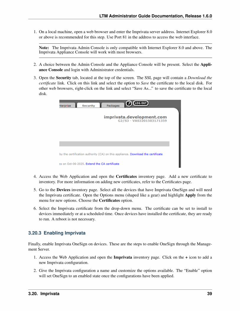
LTM Administrator Guide Documentation, Release 1.6.0
1. On a local machine, open a web browser and enter the Imprivata server address. Internet Explorer 8.0or above is recommended for this step. Use Port 81 in the address to access the web interface.
Note: The Imprivata Admin Console is only compatible with Internet Explorer 8.0 and above. TheImprivata Appliance Console will work with most browsers.
2. A choice between the Admin Console and the Appliance Console will be present. Select the Appli-ance Console and login with Administrator credentials.
3. Open the Security tab, located at the top of the screen. The SSL page will contain a Download thecertificate link. Click on this link and select the option to Save the certificate to the local disk. Forother web browsers, right-click on the link and select “Save As...” to save the certificate to the localdisk.
4. Access the Web Application and open the Certificates inventory page. Add a new certificate toinventory. For more information on adding new certificates, refer to the Certificates page.
5. Go to the Devices inventory page. Select all the devices that have Imprivata OneSign and will needthe Imprivata certificate. Open the Options menu (shaped like a gear) and highlight Apply from themenu for new options. Choose the Certificates option.
6. Select the Imprivata certificate from the drop-down menu. The certificate can be set to install todevices immediately or at a scheduled time. Once devices have installed the certificate, they are readyto run. A reboot is not necessary.
3.20.3 Enabling Imprivata
Finally, enable Imprivata OneSign on devices. These are the steps to enable OneSign through the Manage-ment Server.
1. Access the Web Application and open the Imprivata inventory page. Click on the + icon to add anew Imprivata configuration.
2. Give the Imprivata configuration a name and customize the options available. The “Enable” optionwill set OneSign to an enabled state once the configurations have been applied.
3.20. Imprivata 39
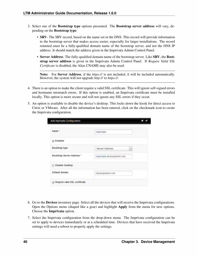
LTM Administrator Guide Documentation, Release 1.6.0
3. Select one of the Bootstrap type options presented. The Bootstrap server address will vary, de-pending on the Bootstrap type:
• SRV- The SRV record, based on the name set in the DNS. This record will provide informationto the bootstrap server that makes access easier, especially for larger installations. The recordreturned must be a fully-qualified domain name of the bootstrap server, and not the DNS IPaddress. It should match the address given in the Imprivata Admin Control Panel.
• Server Address- The fully-qualified domain name of the bootstrap server. Like SRV, the Boot-strap server address is given in the Imprivata Admin Control Panel. If Require Valid SSLCertificate is disabled, the Alias CNAME may also be used.
Note: For Server Address, if the https:// is not included, it will be included automatically.However, the system will not upgrade http:// to https://.
4. There is an option to make the client require a valid SSL certificate. This will ignore self-signed errorsand hostname mismatch errors. If this option is enabled, an Imprivata certificate must be installedlocally. This option is more secure and will not ignore any SSL errors if they occur.
5. An option is available to disable the device’s desktop. This locks down the kiosk for direct access toCitrix or VMware. After all the information has been entered, click on the checkmark icon to createthe Imprivata configuration.
6. Go to the Devices inventory page. Select all the devices that will receive the Imprivata configurations.Open the Options menu (shaped like a gear) and highlight Apply from the menu for new options.Choose the Imprivata option.
7. Select the Imprivata configuration from the drop-down menu. The Imprivata configuration can beset to apply to devices immediately or at a scheduled time. Devices that have received the Imprivatasettings will need a reboot to properly apply the settings.
40 Chapter 3. Device Management
LTM Administrator Guide Documentation, Release 1.6.0
3.20.4 Applying Imprivata through Profiles
Imprivata OneSign can be applied to devices through a profile. For more information on applying profiles,refer to the Profiles section.
Note: Due to a known issue within LeTOS versions 1.2.4 and below, an error may appear during the initialboot after the profile is applied, stating “An error occurred contacting the server: Unknown Error. Pleasecontact your administrator”. Clicking OK will bypass this error and have OneSign operate as normal.
3.20. Imprivata 41
CHAPTER 4
Appliance Settings
At the top of the Administration Page is a link titled Settings. The Settings section handles additionalfeatures that can be used to customize storage locations, groups, and maintenance and recovery options.
4.1 Server Settings
Users can adjust the Web Application settings. The table of settings notes whether the setting is an Integeror a String, the current value of the setting, and the default value. Settings will apply after a server restart.
HostAgent/Heartbeat/Max Sets the maximum amount of time, in seconds, on the interval of a device’sheartbeat. This reduces flooding the network with information from multiple devices at once.
HostAgent/Heartbeat/Min Sets the minimum amount of time, in seconds, on the interval of a device’sheartbeat. This reduces flooding the network with information from multiple devices at once.
HostAgent/Heartbeat/Timeout Sets the amount of time, in seconds, before the server will consider a devicethat is not sending a heartbeat to be offline. Offline devices will display with a red dot in the Devicesinventory table.
Inventory/SyncDeviceNameToHostname Sets a device name to match the device hostname, when the de-vice hostname changes. Set this value to 0 to disable, or 1 to enable. This settings requires a serverrestart to apply the change.
Server/Audit/MaxEntries Sets the maximum number of entries saved in the Audit Trail logs. This valuemay be set at -1 for no entry limit, or 0 to disable audit trail logging.
Server/EthInterface Sets the ethernet interface that the server runs on. Leave this at the default value.
Server/IdleTimeout Sets the time, in seconds, of inactivity before the Web Application automatically logsout. There is a 30 second warning before the logout occurs. Setting this value to -1 disables the idlingtimer. Refreshing the page applies this setting instead of rebooting the server.
Server/LibPath Sets the path for the server’s dependencies. Leave this at the default value.
Server/Logs/MaxEntriesPerDevice Sets the maximum number of log entries saved per device. Setting thisvalue to -1 will remove the entry limit.
Server/MaxActiveDiscoveries Sets the maximum number of devices that Rangewalk may discover simul-taneously. These requests are processed in chunks, so large ranges are acceptable.
42
LTM Administrator Guide Documentation, Release 1.6.0
Server/MaxDeviceActionThreads Sets the maximum number of simultaneous device actions that the servercan perform at once. These requests are processed in chunks, so large ranges are acceptable.
Server/RunPath Sets the path of the server’s executable. Leave this at the default value.
Server/Scep/CertificateRequestAddress Sets the address where the client device will request the certificatefrom. This will usually be http://<WindowsServerDN>/CertSrv/mscep/mscep.dll.
Server/Scep/ChallengeAddress Sets the address where the management server will retrieve the en-rollment challenge information to forward to the client device. This will usually behttp://<WindowsServerDN>/CertSrv/mscep_admin/.
Server/Scep/Identity Sets the anonymous identity used during the first phase of EAP-TLS authentication.This is usually the same account that is running the NDES service on Windows Server.
Server/Scep/Password Sets the password of the user account that will retrieve the SCEP challenge infor-mation.
Server/Scep/Username Sets the username of the user account that will retrieve the SCEP challenge infor-mation. This authenticates against the MSCEP IIS website.
Server/SocketPath Sets the path of the server’s communication socket. Leave this at the default value.
Server/Username Sets the system user that executes the server. Leave this at default value.
Server/ShadowTimeout Sets the time, in seconds, before an idle Shadow connection times out. This timeris specific to inactivity from the administrator’s window, not from the client desktop.
Server/WWWGroup Sets the Unix group that the web server runs under. Leave this at the default value.
Caution: Adjusting the Server/EthInterface, Server/LibPath, Server/RunPath, Server/SocketPath,Server/Username, or Server/WWWGroup settings will result in the server failing to run.
4.2 Licenses
The Licenses tab can be used to apply licensing keys for the VDI Blaster™ software. To add a license tothe inventory:
1. From the Licenses inventory table, click the Add button at the top of the page. This will open theAdd License menu.
2. In the field labeled License Key, enter in the VDI Blaster key exactly as it appears.
3. Once the key has been correctly entered, click on the checkmark at the top right hand corner of theAdd License menu to apply the license to the Management Appliance.
Once a key has been applied, it will appear in the Licenses inventory table. Each key allows a limitednumber of devices to be managed by the Management Appliance, and this number is listed in the AllowedDevices column. Keep in mind that these licenses are applied in a first-come, first-served manner.
4.2. Licenses 43
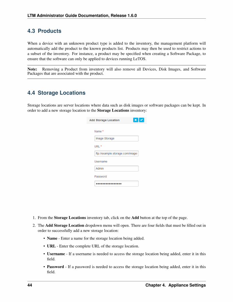
LTM Administrator Guide Documentation, Release 1.6.0
4.3 Products
When a device with an unknown product type is added to the inventory, the management platform willautomatically add the product to the known products list. Products may then be used to restrict actions toa subset of the inventory. For instance, a product may be specified when creating a Software Package, toensure that the software can only be applied to devices running LeTOS.
Note: Removing a Product from inventory will also remove all Devices, Disk Images, and SoftwarePackages that are associated with the product.
4.4 Storage Locations
Storage locations are server locations where data such as disk images or software packages can be kept. Inorder to add a new storage location to the Storage Locations inventory:
1. From the Storage Locations inventory tab, click on the Add button at the top of the page.
2. The Add Storage Location dropdown menu will open. There are four fields that must be filled out inorder to successfully add a new storage location:
• Name - Enter a name for the storage location being added.
• URL - Enter the complete URL of the storage location.
• Username - If a username is needed to access the storage location being added, enter it in thisfield.
• Password - If a password is needed to access the storage location being added, enter it in thisfield.
44 Chapter 4. Appliance Settings
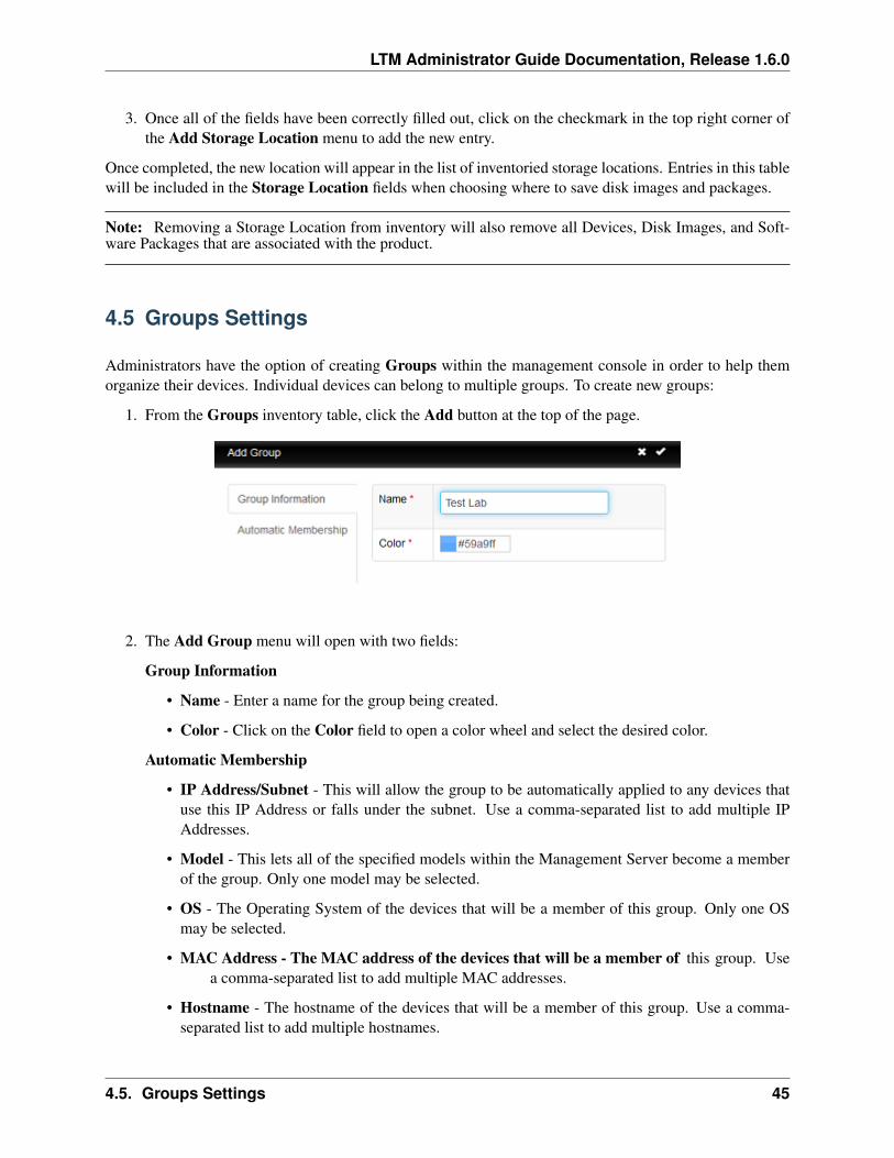
LTM Administrator Guide Documentation, Release 1.6.0
3. Once all of the fields have been correctly filled out, click on the checkmark in the top right corner ofthe Add Storage Location menu to add the new entry.
Once completed, the new location will appear in the list of inventoried storage locations. Entries in this tablewill be included in the Storage Location fields when choosing where to save disk images and packages.
Note: Removing a Storage Location from inventory will also remove all Devices, Disk Images, and Soft-ware Packages that are associated with the product.
4.5 Groups Settings
Administrators have the option of creating Groups within the management console in order to help themorganize their devices. Individual devices can belong to multiple groups. To create new groups:
1. From the Groups inventory table, click the Add button at the top of the page.
2. The Add Group menu will open with two fields:
Group Information
• Name - Enter a name for the group being created.
• Color - Click on the Color field to open a color wheel and select the desired color.
Automatic Membership
• IP Address/Subnet - This will allow the group to be automatically applied to any devices thatuse this IP Address or falls under the subnet. Use a comma-separated list to add multiple IPAddresses.
• Model - This lets all of the specified models within the Management Server become a memberof the group. Only one model may be selected.
• OS - The Operating System of the devices that will be a member of this group. Only one OSmay be selected.
• MAC Address - The MAC address of the devices that will be a member of this group. Usea comma-separated list to add multiple MAC addresses.
• Hostname - The hostname of the devices that will be a member of this group. Use a comma-separated list to add multiple hostnames.
4.5. Groups Settings 45
LTM Administrator Guide Documentation, Release 1.6.0
• Serial Number - The serial number of the devices that will be a member of this group. Usea comma-separated list to add multiple serial numbers.
• Location - The location of the devices that will be a member of this group. Use a comma-separated list to add multiple locations.
• UUID - The UUID of the devices that will be a member of this group. Use a comma-separated list to add multiple UUIDs.
• Disk Image Version - The disk image version of the devices that will be a member of thisgroup. Use a comma-separated list to add multiple disk images.
• Agent Version - The agent version running on the devices that will be a member of thisgroup. Use a comma-separated list to add multiple agents.
• Protocol - The protocol of the devices that will be a member of this group. Select Any,SOAP, or AMQP from the list. Only one protocol may be selected.
3. Once all relevant information has been entered, click on the checkmark at the upper right hand cornerof the Add Group menu. The new group will appear in the Groups inventory.
Note: A device that no longer qualifies as a member of a group will automatically leave the group.
4.6 Database Hotcopy
A back up of the management server can be created from the main Database Hotcopy tab. The methodused is referred to as a ‘Hotcopy’ since the backup is created while the system is running. There is no needto stop or suspend the Management Appliance for the backup. To execute a Hotcopy, perform the followingprocedure:
1. Click on Backup Server button at the top of the Database Hotcopy page.
2. A Backup Server Settings dialogue box will open. Administrators can then select which tablesshould be included within the Hotcopy being created by checking or unchecking the boxes next to thevarious options.
3. Once all of the needed adjustments have been made, click on the checkmark at the top right handcorner of the Backup Server Settings dialogue box to begin making the Hotcopy itself.
4. The result of the Hotcopy will create a binary (.BIN) backup file that will be downloaded to the localmachine. Click Save File and make a note of where the file is saved, as it will be needed it in thefuture to perform a restore.
46 Chapter 4. Appliance Settings
LTM Administrator Guide Documentation, Release 1.6.0
4.7 Restore Server
A restore deletes all existing configuration and data on the Management Appliance and overwrites it withthe information contained in a previously created Hotcopy backup file. To perform a restore, follow thesesteps:
1. In the Database Hotcopy tab, click the Restore Server button at the top of the page.
2. A Restore Server dialogue box will open. In the Choose File field, navigate to the .bin file containingthe server data needed.
3. After the path to the backup file has been entered, click the checkmark at the top right corner of theRestore Server dialogue box to restore the server settings to those contained in the Hotcopy.
4. In the Database Hotcopy tab, click the Legacy Restore button at the top of the page.
5. A Legacy Restore dialogue box will open. In the Choose File field, navigate to the .bin file containingthe server data needed. Below the Browse button is an option that states “Force restore even if somerecords can’t be processed”. This option is available due to differences that can occur between alegacy version and the current version of the Management Appliance, but is not required.
6. After the path to the backup file has been entered, click the checkmark at the top right corner of theLegacy Restore dialogue box to restore the server settings to those contained in the Hotcopy.
4.7. Restore Server 47
LTM Administrator Guide Documentation, Release 1.6.0
4.8 Permissions
Permissions can be set for the accounts of Active Directory groups that will be using the ManagementAppliance. To select permissions for group accounts, the Management Appliance must first join ActiveDirectory. Refer to the activedirectory-reference section.
1. Click on the Permissions button to access the Permissions inventory table.
2. Create a new group by clicking on the Add button at the top of the page.
3. The Groups dropdown menu will display all groups that were included during the Active Directoryconfiguration process. A search bar is also available to locate specific groups. If a group is notdisplaying, click on the Refresh button to reload the group inventory. The Restrict to Groups optionwill restrict an Active Directory group’s permissions to devices within the specified device groups.
4. Once a group has been selected, all of the Read/Write access can be chosen for that group. Clickon the Read All or Write All buttons to allow privileges for all options. Write permissions are notavailable without Read permissions.
5. After all permissions have been set for that group, click on the checkmark at the top right corner toapply those permissions settings. Repeat this process for all groups as necessary. It is recommendedthat any Administrator groups have full Read and Write access.
Once Permissions have been established, Active Directory accounts may be used as login credentials.
4.8.1 Role-Based Inventory Filter
If necessary, an account may also have limited access to certain settings and inventories with a Role-BasedInventory Filter in place. Similar to standard Permissions, this inventory filter is applied based on ActiveDirectory group memberships and restrictions.
4.8.2 Extra Permissions
Miscellaneous permission options are available as optional inclusions for group and account permissions.These options can be set based on security preferences for devices.
Override Shadow Confirmation This option will determine if a prompt will appear for devices that theManagement Appliance requests to Shadow. This prompt, if accepted, grants the Management Appli-ance permission to shadow. If Allow Override is enabled, the device will simply be notified that it isbeing shadowed.
Allow Shadow without Device Write Permissions This option will allow groups without write permis-sions to Shadow a device. This may be necessary if an Active Directory group is restricted to certaindevice groups or otherwise does not need device write permissions.
Warning: Enabling this option will give the Shadow initiator the ability to open and adjust ControlPanel settings of the device that is being Shadowed. To prevent potential adjustments, the Control Panelshould be password protected before a shadowing session is started. For more information on ControlPanel security, refer to device’s respective operating system guide.
48 Chapter 4. Appliance Settings
LTM Administrator Guide Documentation, Release 1.6.0
4.9 Appliance Upgrades
The following is the recommended procedure for upgrading the Management Appliance to a newer version:
1. Backup - Back up the server’s current configuration and data prior to performing an upgrade usingthe Hotcopy procedure. Refer to the Database Hotcopy section for details on this step.
2. Upgrade -
• Shut down the appliance server (Select option 9, Halt Machine, from the Main Menu).
• Download the latest management console appliance.
• Extract the contents and point the VMware Server to the new file.
• Restart the virtual appliance.
3. Restore- Once the upgrade is finished and the new appliance is online, the management server willbe ready for restoration. Refer to the Restore Server section for details on the restore process.
4.10 Package Management
Packages are available for the Management Appliance, allowing an Administrator to remotely upgrade theversion of the server without performing a virtual appliance replacement.
Note: In order to perform a successful upgrade, the previous version of the Management Appliance mustbe in use. The Management Appliance will only accept upgrades from its subsequent version. The upgradewill not go through if the appliance is at least two versions behind the package’s version.
1. Download all available package files, then access the Settings page of the Management Server.
2. Click on Add Package button at the top of the Package Management page. Click on the Browsebutton and locate the first package file. Once the file has been selected, click on the checkmark iconon top right hand corner of the Add Package dialogue box to begin the package application.
3. The first package will begin to apply itself. This may take a few moments to complete. As eachpackage is being applied, the Logs will update automatically, displaying the current progress anderrors, if any. When the first package finishes applying, repeat the process to apply the next package.The final package will initiate the update process. Once finished, the Management Appliance willautomatically restart to apply the packages. The restart process may take a few moments to complete.During this time, the web user interface will be inaccessible until the restart is finished. Once thisprocess is completed, the Management Appliance will clean up the package and the server will beready for use.
Warning: It is important to make sure that the packages are applied in order. Failure to do so may resultin errors during the update process.
4.9. Appliance Upgrades 49
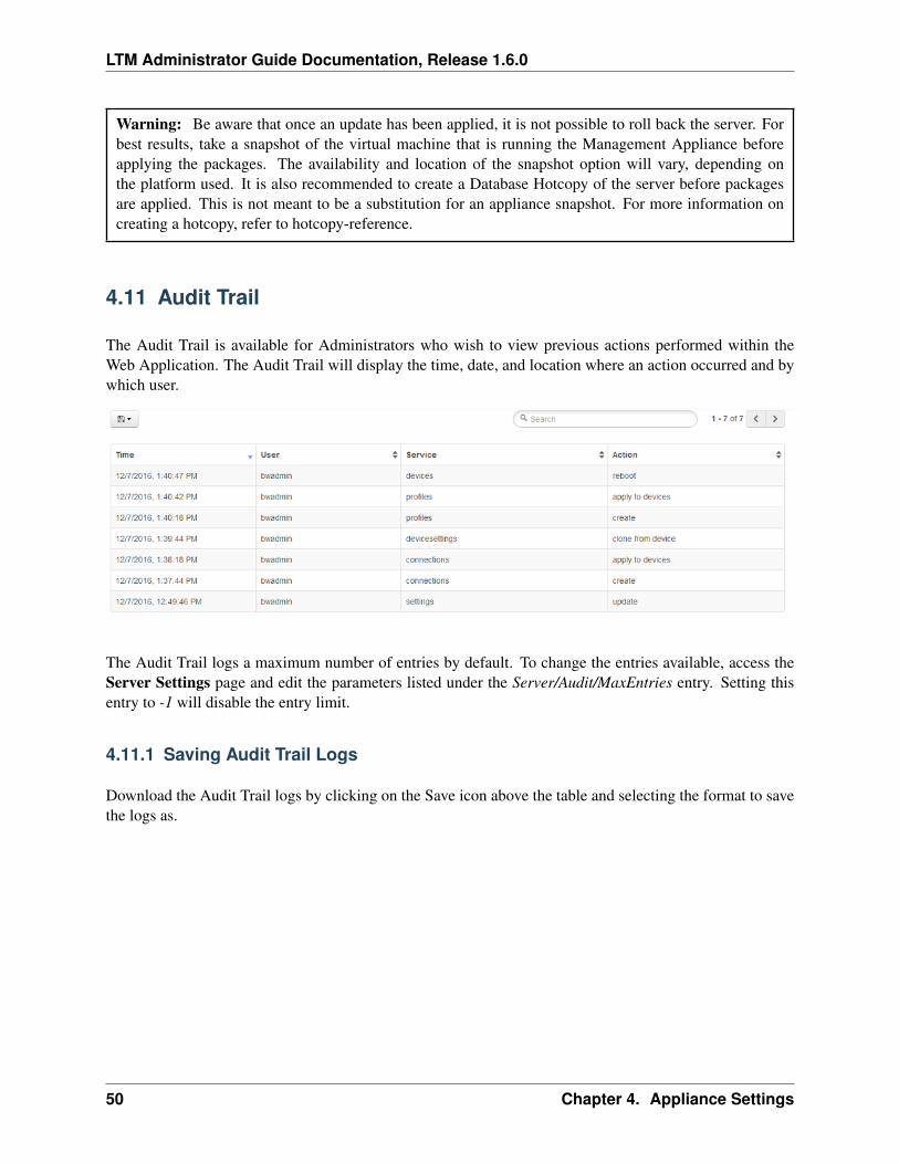
LTM Administrator Guide Documentation, Release 1.6.0
Warning: Be aware that once an update has been applied, it is not possible to roll back the server. Forbest results, take a snapshot of the virtual machine that is running the Management Appliance beforeapplying the packages. The availability and location of the snapshot option will vary, depending onthe platform used. It is also recommended to create a Database Hotcopy of the server before packagesare applied. This is not meant to be a substitution for an appliance snapshot. For more information oncreating a hotcopy, refer to hotcopy-reference.
4.11 Audit Trail
The Audit Trail is available for Administrators who wish to view previous actions performed within theWeb Application. The Audit Trail will display the time, date, and location where an action occurred and bywhich user.
The Audit Trail logs a maximum number of entries by default. To change the entries available, access theServer Settings page and edit the parameters listed under the Server/Audit/MaxEntries entry. Setting thisentry to -1 will disable the entry limit.
4.11.1 Saving Audit Trail Logs
Download the Audit Trail logs by clicking on the Save icon above the table and selecting the format to savethe logs as.
50 Chapter 4. Appliance Settings
LTM Administrator Guide Documentation, Release 1.6.0
4.12 Automatic SCEP
Automatic SCEP server support is available on LeTOS for users who wish to use an automatic method foraccessing secure networks.
SCEP is currently only supported on a Windows Server (NDES).
Note: LTM and the NDES server will both need to be visible on the unsecured network for this process.
4.12.1 Deploying SCEP
The following settings must be entered on the Server Settings page before SCEP can function properly ondevices. See serversettings for more information on Server Settings.
Server/Scep/CertificateRequestAddress Sets the address where the client device will request the certificatefrom. This will usually be http://<WindowsServerDN>/CertSrv/mscep/mscep.dll.
Server/Scep/ChallengeAddress Sets the address where the management server will retrieve the en-rollment challenge information to forward to the client device. This will usually behttp://<WindowsServerDN>/CertSrv/mscep_admin/.
Server/Scep/Identity Sets the anonymous identity used during the first phase of EAP-TLS authentication.This is usually the same account that is running the NDES service on Windows Server.
Server/Scep/Password Sets the password of the user account that will retrieve the SCEP challenge infor-mation.
Server/Scep/Username Sets the username of the user account that will retrieve the SCEP challenge infor-mation. This authenticates against the MSCEP IIS website.
After applying these settings, restart the LTM server. Once LTM resumes activity, SCEP can be provisionedfor devices with the following steps:
1. Access the Web Application. Open the Settings tab at the top and click on the SCEP inventory page.
2. Click on the + icon to add a new device to support SCEP. Enter the device’s MAC address to add it tothe inventory.
Note: Devices that are not part of the LTM Appliance’s device inventory are included upon completion ofthis process.
3. Power on the device that has been configured for SCEP and connect to the unsecured ethernet. Oncethe device connects to the Management Server, LTM will begin SCEP enrollment process by request-ing a challenge password from the NDES server and sending the response along with the certificaterequest address to the device. The device will then request a certificate using the challenge passwordprovided to it by LTM. upon success, the device will receive the SCEP server’s CA certificate, its ownclient certificate and private key. From there, 802.1X will be configured, overwriting any previous802.1X configurations.
4.12. Automatic SCEP 51

LTM Administrator Guide Documentation, Release 1.6.0
Once SCEP is deployed with all relevant information, connect the device to the secure 802.1X port. Ifthe device was already part of the Appliance’s device inventory, reboot it before connecting to the 802.1Xnetwork.
52 Chapter 4. Appliance Settings
CHAPTER 5
Terminology
This section covers terms and descriptions that LTM uses throughout the user interface.
5.1 General Terms
Navigation Tabs A term used to reference the various tabs located on the left-hand side of the LTM Ad-ministration screen. These tabs provide quick access to the various inventory tables.
Inventory Tables Inventory Tables are the lists of items presented in a table format that is located in themiddle area of the LTM Administration screen. Upon clicking on Navigation Tabs such as Devices orProfiles, among others, an inventory table will open for those specific sections.
Device This is the device in front of the user, to which their screen, keyboard and mouse are attached. InLTM, the Devices tab will display an inventory containing all of the devices being managed by theLTM server.
Shadow Shadow is a method that allows Administrators and Users with approved permissions to shadowone host device at a time. This allows LTM to view and interact with the desktop of the host device.
Connection A connection is a method used to connect a device to a remote server. The Connections tab inLTM will display an inventory containing all of the RDP, ICA, VMware View, and other connectionsthat have been created.
Profile A profile is a combination of device settings and connections that can be created in order to provideeasily applied groupings of settings to multiple devices. The Profiles tab is where the administratorcan create, edit, and apply these profiles to the devices.
Disk Image A disk image is a file that contains an all encompassing set of information that can be appliedto a device, including the operating system. The Disk Images tab opens the inventory table that allowsusers to create, edit, and apply disk images as needed.
Device Settings Device settings are limited to the display, sound, keyboard, mouse, and password config-urations for a device. The Device Settings tab displays the inventory table containing the groups ofsettings that have been cloned from devices. Applying device settings to a device is performed throughthe Device inventory table.
Certificate Certificates provide users with the credentials needed to access certain websites or services.While certificates can be obtained in a number of ways, the Certificates tab in LTM allows users to
53
LTM Administrator Guide Documentation, Release 1.6.0
store specific certificates that can then be applied to devices through the Device inventory table.
Software Software packages allow administrators to patch existing images on devices or update to newversions of existing software. The Software tab in LTM displays the inventory of administrator-approved packages.
Tasks Tasks allow users to schedule device activity for later execution. Tasks must be scheduled from theDevices tab. The Tasks tab will allow users to view the status and schedule of all tasks that have beenset on the server.
Imprivata Imprivata OneSign provides one-touch single sign-on solutions for operating systems that sup-port it. A certificate may be required. The Imprivata tab will display all available OneSign configura-tions that may be applied to devices.
Logs Logs are records of server events that administrators can use to keep track of what is occurring withthe managed devices.
Settings The Settings tab is used in LTM as a reference to the process of maintaining and updating theLTM server itself. The Settings tab has several subsections that allow an administrator to carry out anumber of useful processes to keep the server running smoothly.
Help Help is a tab where the user can view a number of resources to assist with running LTM. There is alsoa brief administration guide and a link to the full length LTM Administration Guide.
5.2 Device Details
Name Name of the device. For newly discovered devices, the default name given to the device is its host-name. Change the name of a device by left-clicking on the desired device in the Devices table andentering a new name in this field. Click on the check mark to apply these changes.
Description A human readable description of the device, as entered by the administrator.
Last Contact The date and time of the last heartbeat sent. This will automatically update every 60 secondsby default, so long as a connection can be established.
MAC Address The ethernet address of the device.
Hostname The hostname of the device.
IP Address The IP address assigned to the device.
Serial Number The serial number of the device.
Location A human readable location such as “Test Lab” or “Office 325.” This field was used in olderversions of the server, consider using Groups instead to convey this information.
UUID The universally unique identifier (UUID) for the device. This is burned into the device at the factoryand is used to uniquely identify the device as its network address changes.
Disk Image Version The version of the disk image the device is currently using.
Disk Image MD5 Hash The hash of the disk image being run by the device. This can be auto- generated ifthe disk image came from an ftp://, http://, or https:// server.
54 Chapter 5. Terminology
LTM Administrator Guide Documentation, Release 1.6.0
Agent Version The version of the LTM Agent that the device is currently using to communicate with theLTM server.
Product The brand, device name, and operating system that the device is running, as reported by the devicevia the LTM Agent.
Groups The group or groups that the device is assigned to.
5.3 Connection Details
There are a wide variety of connection types that can be managed through the LTM software. Since eachconnection type has different options available, this section is broken down into the different panes that arepresent for each connection type.
5.3.1 JavaWS
JavaWS connects to Citrix desktops through the JavaWS Client.
Basic Information
Name The name of the connection. The name is a required field when a new connection is created.
Local Display Name The local display name is what the connection will be labeled with on the device.This field is required in order to create a new connection.
Description A description such as “Kiosk Connection” or “Presentation Connection.” The description fieldis optional, but it is recommended to use descriptions to help organize connections.
Protocol The protocol used in the connection is displayed here.
General
Server URL The name or IP address of the JavaWS server.
Autostart Causes the connection to start as soon as the device is powered on.
Auto Restart Causes the connection to be restarted if it is closed. This is useful for administrators that wishto limit the ability of a user to access the device.
Disable Desktop This will disable desktop access, ensuring that users only access this specific workstationwith the specific credentials applied to the connection. Logging off from the server will power off thethin client, and powering on the thin client will bypass the operating system’s desktop and immediatelylog in to the server. This feature is not supported for Windows-based operating systems.
5.3.2 AnyConnect VPN
The AnyConnect VPN protocol allows connections to a VPN service.
5.3. Connection Details 55
LTM Administrator Guide Documentation, Release 1.6.0
Basic Information
Name The name of the connection. The name is a required field when a new connection is created.
Local Display Name The local display name is what the connection will be labeled with on the device.This field is required in order to create a new connection.
Description A description such as “Kiosk Connection” or “Presentation Connection.” The description fieldis optional, but it is recommended to use descriptions to help organize connections.
Protocol The protocol used in the connection is displayed here.
General Settings
Host The host address or IP address of the VPN service.
Username The default username for the VPN connection. Leaving this field blank will allow those whouse this connection to log in with their desired username when they connect.
Group The default workgroup that will be accessed.
5.3.3 Firefox
Firefox is a local web browser. This connection can not be applied to Windows-based operating systems.
Basic Information
Name The name of the connection. The name is a required field when a new connection is created.
Local Display Name The local display name is what the connection will be labeled with on the device.This field is required in order to create a new connection.
Description A description such as “Kiosk Connection” or “Presentation Connection.” The description fieldis optional, but it is recommended to use descriptions to help organize connections.
Protocol The protocol used in the connection is displayed here.
General Settings
Start URL The URL that Firefox will automatically open upon starting.
Autostart Allows the administrator to cause a connection to start as soon as the device is powered on.
Auto Restart Causes the connection to be restarted if it is closed. This is useful for administrators that wishto limit the ability of a user to access the device.
Disable Desktop This will disable desktop access, ensuring that users only access this specific workstationwith the specific credentials applied to the connection. Logging off from the server will power off thethin client, and powering on the thin client will bypass the operating system’s desktop and immediatelylog in to the server. This feature is not supported for Windows-based operating systems.
56 Chapter 5. Terminology
LTM Administrator Guide Documentation, Release 1.6.0
Proxy Settings
Select a Proxy Setting Allows users to select from the various proxy setting options.
Kiosk Mode
Show Menubar Determines whether or not the menubar is displayed to the user.
Use Appmenu Button If the menubar is enabled, an appmenu button may be available for users who wishto access non-standard features. This is a legacy option to support older versions of the application.
Enable Kiosk Mode Toggles Kiosk Mode on or off. When in Kiosk mode, the user is only able to access alimited number of the options Firefox contains.
Show Toolbar Toggles the Firefox toolbar on or off.
Autohide Navbar in Kiosk Toggles whether or not the user can access the Firefox navigation bar.
Allow Quit Determines whether or not the user can quit Firefox.
Advanced Options
Enable Javascript Toggles javascript capabilities for Firefox.
Enable Popup Blocker Toggles the popup blocker abilities of Firefox.
5.3.4 RDP
The RDP protocol is used to connect to Microsoft Windows Device Servers.
Basic Information
Name The name of the connection. The name is a required field when a new connection is created.
Local Display Name The local display name is what the connection will be labeled with on the device.This field is required in order to create a new connection.
Description A description such as “Kiosk Connection” or “Presentation Connection.” The description fieldis optional, but it is recommended to use descriptions to help organize connections.
Protocol The protocol used in the connection is displayed here.
General
Server Name The name or IP address of the RDP server.
Port The port used to access the RDP server.
Username The default username for the RDP server. Leaving this field blank will allow those who use thisconnection to log in with their desired username when they connect.
5.3. Connection Details 57
LTM Administrator Guide Documentation, Release 1.6.0
Password Setting a password in this field, combined with entering a username above, will enable automaticlogin as the specified user. This is a legacy option to ensure compatibility with older devices.
Domain The domain name of the user being logged in.
Display
Display The three options listed allow the administrator to set a default display setting for users using thisconnection. If no option is specified in LTM, the session opens in full screen mode.
Color depth for this connection Allows the administrator to specify a desired color depth for those usingthis connection.
Use All Monitors This option, when selected, will allow multi-monitor usage for the RDP connection.
Local Resources
Sound Settings Creates a default state for sounds to play through this connection.
Other Settings The administrator can enable a variety of different functions to be available to those usingthis connection by checking the boxes next to the desired settings.
Start a Program
Program path and filename Entering the path and filename of a program in this field makes it so that whenthis connection is used, only that specific program can be used in the RDP session.
Working Directory Can be used in conjunction with Program path and filename to specify the specificdirectory where the file can be found.
Maximize Program Runs the program at maximum size.
RD Gateway
RD Gateway Host The host that will be used for RD Gateway.
RD Gateway Credential Source The method of login access for RD Gateway. You can select passwordentry, smartcard access, or have the credential source selected on login.
RD Gateway Profile Method The profile method that will be used for RD Gateway. You can select adefault mode or use specific settings.
RD Gateway Usage The usage for RD Gateway. You can select always, only if direct connection is un-available, or just use default settings.
Reuse RD Gateway Credentials When enabled, this will allow the RD Gateway credentials to be reused.
58 Chapter 5. Terminology
LTM Administrator Guide Documentation, Release 1.6.0
RemoteApp
Application Name Sets the name of the Application.
Application The filename of the Application to be used.
Command Line Enables command line use.
Expand Command Line Expands the Command Line.
Expand Working Directory Expands the working directory.
Application File The filepath for the application.
RemoteApp Mode Set the session for RemoteApp. Users can select between a normal session and a Re-moteApp session.
Disable RemoteApp Support Checking When selected, this will disable RemoteApp Support Checking.
Performance
Experience Options This allows adjustments to various settings to suit the user experience desired. Theseoptions will determine the connection speed of the network.
Enable bitmap caching This option will allow common .bmp-based images from the session desktop to bestored on the local hard drive. Selecting this option may improve connection performance.
Disable cursor from blinking Indicates that cursor blinking should be disabled during the session.
Scale desktop when resizing session window If the connection session window can be resized, this willallow the session desktop to scale with the window resizing.
Enable window manager’s key bindings By default RDP® attempts to grab all keyboard input when it isin focus.
Display the connection bar A connection bar will display at the top when a session is active. This connec-tion bar displays the connection’s address and offers other options.
Attach to the console of the server The session will connect to the console of the server (requires Win-dows® Server 2003 or newer).
Enable RemoteFX Toggles whether or not the connection will use the RemoteFX® feature.
Enable font smoothing This will enable ClearType for the RDP session, making font appear smooth andmore clear.
Options
Enable compression of the RDP datastream Depending on network latency, utilizing datastream com-pression can improve overall communication performance.
Autostart Causes the connection a connection to start as soon as the device is powered on.
Auto Restart Causes the connection to be restarted if it is closed. This is useful for administrators that wishto limit the ability of a user to access the device.
5.3. Connection Details 59
LTM Administrator Guide Documentation, Release 1.6.0
Restart When enabled, the session will restart if the server is disconnected.
Enable CredSSP This will enabled the Security Support Provider for the server. This option is enabled bydefault.
Disable Desktop This will disable desktop access, ensuring that users only access this specific workstationwith the specific credentials applied to the connection. Logging off from the server will power off thethin client, and powering on the thin client will bypass the operating system’s desktop and immediatelylog in to the server. This feature is not supported for Windows-based operating systems.
5.3.5 X11
X11 connections are used to run an X11 application through SSH or to connect to a server via XDMCP.
Basic Information
Name The name of the connection. The name is a required field when a new connection is created.
Local Display Name The local display name is what the connection will be labeled with on the device.This field is required in order to create a new connection.
Description A description such as “Kiosk Connection” or “Presentation Connection.” The description fieldis optional, but it is recommended to use descriptions to help organize connections.
Protocol The protocol used in the connection is displayed here.
General
Session Type The session type for the X11 connection. Users can choose between using an XDMCP con-nection or using the X11 SSH application.
Server URL The URL (or IP address) of the X11 server.
Username The default username for the X11 session. Leaving this field blank will allow those that use thisconnection to log in with their desired username when they connect.
Password Setting a password in this field, combined with entering a username above, will enable automaticlogin as the specified user.
Application Name If the session type selected is X11 SSH App, then an application’s filepath can be en-tered here. Otherwise this field can be left blank.
Screen Resolution The screen resolution for the X11 session. If an X11 SSH App session is in use, thensome applications may not support all available resolutions.
Autostart Causes the connection to start as soon as the device is powered on.
Auto Restart Causes the connection to be restarted if it is closed. This is useful for administrators that wishto limit the ability of a user to access the device.
60 Chapter 5. Terminology
LTM Administrator Guide Documentation, Release 1.6.0
Disable Desktop This will disable desktop access, ensuring that users only access this specific workstationwith the specific credentials applied to the connection. Logging off from the server will power off thethin client, and powering on the thin client will bypass the operating system’s desktop and immediatelylog in to the server. This feature is not supported for Windows-based operating systems.
5.3.6 ICA
The ICA protocol is used to establish connections to Citrix servers.
Basic Information
Name The name of the connection. The name is a required field when a new connection is created.
Local Display Name The local display name is what the connection will be labeled with on the device.This field is required in order to create a new connection.
Description A description such as “Kiosk Connection” or “Presentation Connection.” The description fieldis optional, but it is recommended to use descriptions to help organize connections.
Protocol The protocol used in the connection is displayed here.
Connection
Connection Type Allows the connection setting to be changed between a local area network and a widearea network.
Server Location The IP address of the ICA server.
Protocol The type of protocol being used to connect to the ICA server.
Session Type Allows the administrator to select if the connection should be a server connection or a pub-lished application.
Name The name of the server or published application desired for this connection.
Options
An administrator can use the dropdown menus in the Options pane to select a number of different displayand audio features to customize the connection.
Autostart Allows the administrator to cause a connection to start as soon as the device is powered on.
Auto Restart Causes the connection to be restarted if it is closed. This is useful for administrators that wishto limit the ability of a user to access the device.
Use data compression Depending on network latency, utilizing datastream compression can improve over-all communication performance.
Use disk cache for bitmaps Determines whether or not the disk cache is used to when processing bitmaps.
5.3. Connection Details 61
LTM Administrator Guide Documentation, Release 1.6.0
Disable Desktop This will disable desktop access, ensuring that users only access this specific workstationwith the specific credentials applied to the connection. Logging off from the server will power off thethin client, and powering on the thin client will bypass the operating system’s desktop and immediatelylog in to the server. This feature is not supported for Windows-based operating systems.
Firewall Settings
Use alternate address for firewall connection If checked, allows users to use the Proxy Type options.
Proxy Type Allows users to choose between SOCKS or HTTPS for the firewall proxy.
Proxy Address The IP address of the proxy server.
Proxy Port The proxy port number to be used for this connection.
User Logon
Username The default username for the ICA connection. Leaving this field blank will allow those that usethis connection to log in with their desired username when they connect.
Domain The domain name of the user being logged in.
Application
Application Entering the path and filename of a program in this field makes it so that when this connectionis used, only that specific program can be used in the ICA session. This field does not need to be filledout if the session type is a published application.
Working Directory Can be used in conjunction with Application to specify the specific directory wherethe file can be found.
5.3.7 XenAppView
The XenAppView protocol is also used to establish connections to Citrix servers.
Basic Information
Name The name of the connection. The name is a required field when a new connection is created.
Local Display Name The local display name is what the connection will be labeled with on the device.This field is required in order to create a new connection.
Description A description such as “Kiosk Connection” or “Presentation Connection.” The description fieldis optional, but it is recommended to use descriptions to help organize connections.
Protocol The protocol used in the connection is displayed here.
62 Chapter 5. Terminology
LTM Administrator Guide Documentation, Release 1.6.0
General Settings
Server Address The URL or IP address of the XenAppView server.
Username The default username for the XenApView connection. Leaving this field blank will allow thosethat use this connection to log in with their desired user name when they connect.
Domain Name The domain name of the user being logged in.
Autostart Allows the administrator to cause a connection to start as soon as the device is powered on.
Auto Restart Causes the connection to be restarted if it is closed. This is useful for administrators that wishto limit the ability of a user to access their desktop.
Launch in Fullscreen Launches the desktop in XenAppView’s fullscreen mode.
Disable Desktop This will disable desktop access, ensuring that users only access this specific workstationwith the specific credentials applied to the connection. Logging off from the server will power off thethin client, and powering on the thin client will bypass the operating system’s desktop and immediatelylog in to the server. This feature is not supported for Windows-based operating systems.
5.3.8 Internet Explorer
Internet Explorer is the native browser on Windows-based clients.
Basic Information
Name The name of the connection. The name is a required field when a new connection is created.
Local Display Name The local display name is what the connection will be labeled with on the device.This field is required in order to create a new connection.
Description A description such as “Kiosk Connection” or “Presentation Connection.” The description fieldis optional, but it is recommended to use descriptions to help organize connections.
Protocol The protocol used in the connection is displayed here.
General Settings
Start URL The URL that Internet Explorer will automatically open upon starting.
Enable Kiosk Mode Toggles Kiosk Mode on or off. When in Kiosk mode, the user is only able to access alimited number of the options Internet Explorer contains.
Autostart Allows the administrator to cause a connection to start as soon as the device is powered on.
Auto Restart Causes the connection to be restarted if it is closed. This is useful for administrators that wishto limit the ability of a user to access the device.
5.3. Connection Details 63
LTM Administrator Guide Documentation, Release 1.6.0
5.3.9 VMware Horizon View
VMware Horizon View connections are used for connecting to VMware Servers.
Basic Information
Name The name of the connection. The name is a required field when a new connection is created.
Local Display Name The local display name is what the connection will be labeled with on the device.This field is required in order to create a new connection.
Description A description such as “Kiosk Connection” or “Presentation Connection.” The description fieldis optional, but it is recommended to use descriptions to help organize connections.
Protocol The protocol used in the connection is displayed here.
General
Server URL The URL (or IP address) of the VMware Horizon View server.
Username The default username for the VMware Horizon View session. Leaving this field blank will allowthose that use this connection to log in with their desired username when they connect.
Password Setting a password in this field, combined with entering a username above, will enable automaticlogin as the specified user.
Caution: Passwords cannot be deleted once they have been applied to a connection. If the passwordfield needs to be emptied, a new connection must be made.
Domain The domain name of the user being logged in.
Desktop Name The name of the desktop that the user will connect to. If no desktop is specified, the desktopinventory will display upon user login and a selection can be made there.
Enable Background on Startup This will allow VMware Horizon View to run in the background on startup. This is a legacy option available for devices that are running older versions of the agent.
Protocol The protocol for the server that is being accessed. VMware Horizon View supports RDP andPCOIP protocols.
Desktop Layout The window layout for the VMware Horizon View connection. This option offers a selec-tion of preferred window-mode sizes and a multi-monitor option for extended desktops.
Autostart Causes the connection to start as soon as the device is powered on.
Auto Restart Causes the connection to be restarted if it is closed. This is useful for administrators that wishto limit the ability of a user to access the device.
Disable Desktop This will disable desktop access, ensuring that users only access this specific workstationwith the specific credentials applied to the connection. Logging off from the server will power off thethin client, and powering on the thin client will bypass the operating system’s desktop and immediatelylog in to the server. This feature is not supported for Windows-based operating systems.
64 Chapter 5. Terminology
LTM Administrator Guide Documentation, Release 1.6.0
Options
Disable Menubar The VMware Horizon View menu bar will be hidden from the desktop.
Run Once This will close the VMware Horizon View client completely upon logging out or disconnectingfrom the server, rather than returning users to the desktop selection options of the client.
Enable kiosk login mode A kiosk-based login mode will be enabled. This option will need to be enabledserver-side in order to function.
Lock the server URL field This option prevents users from changing the server or selecting a differentserver from the client’s server selection menu.
Start a Program
Application Name The name of the application that will be run upon server login.
Application Size The window layout for the application that will be run. This option offers a selection ofpreferred window-mode sizes and a multi-monitor option for extended desktops.
5.3.10 SSH
The SSH protocol is used to connect to a device through SSH.
Basic Information
Name The name of the connection. The name is a required field when a new connection is created.
Local Display Name The local display name is what the connection will be labeled with on the device.This field is required in order to create a new connection.
Description A description such as “Kiosk Connection” or “Presentation Connection.” The description fieldis optional, but it is recommended to use descriptions to help organize connections.
Protocol The protocol used in the connection is displayed here.
General
Server Address The hostname or IP address of the device to SSH into.
Username The default username to login through SSH. Leaving this field blank will allow those who usethis connection to log in with their desired username when they connect.
Port The port used to access the device via SSH. Port 22 is the default port.
Host Key The encryption type and host key for the connection.
5.3.11 Telnet
The Telnet protocol is used to connect to a device through Telnet.
5.3. Connection Details 65
LTM Administrator Guide Documentation, Release 1.6.0
Basic Information
Name The name of the connection. The name is a required field when a new connection is created.
Local Display Name The local display name is what the connection will be labeled with on the device.This field is required in order to create a new connection.
Description A description such as “Kiosk Connection” or “Presentation Connection.” The description fieldis optional, but it is recommended to use descriptions to help organize connections.
Protocol The protocol used in the connection is displayed here.
General
Type The type of Telnet connection being run. Certain types have different login options available.
Server Address The hostname or IP address of the device to Telnet into.
Username The default username to login through Telnet. Leaving this field blank will allow those who usethis connection to log in with their desired username when they connect. This is only available forType: TELNET.
Port The port used to access the device via Telnet. The default port will change if SSL is enabled ordisabled.
Use SSL Enables or disables the use of SSL.
5.4 Profile Details
Name The name of the profile. The name is a required field when a new profile is being created.
Description A human readable description such as “Demonstration Profile.” The description field is op-tional, but it is generally a good idea to utilize descriptions to help organize profiles.
Mode The Mode dropdown menu provides four methods that can be used to apply the selected profileto devices. These modes are prioritized, meaning that if users attempt to apply two profiles to thesame device using different modes, the profile with the higher priority mode assigned to it will beimplemented while the other is ignored. These modes, in order of priority from highest to lowest, are:
Default Profile A profile created in the Default Profile mode is automatically applied to any newdevice that connects to the LTM server.
Select Devices The administrator directly chooses which devices the profile is applied to. If two ormore profiles with overlapping options are applied to the same device using the Select Devicesmode, the most recently applied profile takes precedent for that option. If Select Devices is cho-sen, the Devices dropdown menu will appear to allow the administrator to select which devicesto apply the profile to.
Terminal Details A profile created with the Apply by terminal details mode specifically targets cer-tain types of devices to apply itself to. Device name, IP Address or range, model, and operatingsystem are all options an administrator can use to specify devices. If Apply by terminal details is
66 Chapter 5. Terminology
LTM Administrator Guide Documentation, Release 1.6.0
chosen, Details options will appear. The administrator can fill out the fields as needed to targetthe desired devices.
Group Membership A profile created for specific groups that devices apply to. The profile can applyto multiple groups, if necessary. If Apply by group membership is chosen, the Groups dropdownmenu will appear to allow the administrator to select which group to apply the profile to.
Disk Image An administrator can use the dropdown menu in the Disk Image section to select which saveddisk image will be included in the profile.
Connections An administrator can use the dropdown menu in the Connections section to select which savedconnections will be included in the profile.
Device Settings An administrator can use the dropdown menu in the Device Settings section to select whichsaved device settings will be included in the profile.
Certificates An administrator can use the dropdown menu in the Certificates section to select which savedcertificates will be included in the profile.
Software Packages An administrator can use the dropdown menu in the Software Packages section to selectwhich saved software packages will be included in the profile.
Imprivata Configuration An administrator can use the dropdown menu in the Imprivata Configurationsection to select which saved OneSign configuration will be included in the profile.
5.5 Disk Image Details
5.5.1 Basic Information
Name The name given to a disk image when it is created. This is a mandatory field when creating a newdisk image, but can be changed later if needed.
Description Entering a description for a disk image is optional, but doing so is highly recommended.
Filename The filename to be given to the disk image file. The name of the file and the file extension needto be entered here.
Checksum The hash for the disk image. This field will auto-generate if the disk image is coming from anHTTP, HTTPS, or FTP server.
Product Select the product of the disk image from drop-down menu.
Storage Location The storage location that will hold the disk image. The location must have been previ-ously entered in the server’s Storage Location tab.
5.5.2 Legacy Options
These options are for when a legacy disk image is being added to the server.
MD5 Sum This is the MD5 sum of the disk image. When applied via a profile, if the two images are thesame, nothing will happen. If they differ, the device will apply the image in the profile.
5.5. Disk Image Details 67
LTM Administrator Guide Documentation, Release 1.6.0
Note: If a thin client that is using LeTOS 1.1 or 1.2 is receiving a disk image upgrade through a WindowsShare (cifs://) storage location, the SHA1 of the disk image will need to be entered in place of the MD5Sum. This is always required regardless of legacy status.
5.6 Device Setting Details
5.6.1 Basic Information
Name A mandatory field used to provide a name for the saved set of device settings.
Description An optional description that can be used to provide more information about what is containedin the saved device settings.
Device Settings A list containing all of the cloned settings. Sound, network, time, input, display, permis-sions, USB permissions, printers, and persistence are all possible options.
5.7 Certificate Details
5.7.1 Name and Details
Name The name given to the certificate by the administrator.
Description An optional field used to provide more details about the certificate.
Certificate The Browse button allows users to browse through files in order to locate a certificate to includein the Certificates section.
5.7.2 Certificate Details
The fields viewed through View Certificate can not be altered manually. These fields are automatically filledin when a certificate has been created or updated and are populated by information provided by the certificateitself. To access this information, click on the Information button that is next to the certificate’s name.
Organization The name of the certificate provider.
Organizational Unit The classification of the certificate in the digital hierarchy.
Common Name A name given to the certificate by its creators.
Country The country where the certificate was created.
State The state (in the United States) where the certificate was created.
Locality The city or general area where the certificate was created.
Effective Date The date that the certificate becomes valid for use.
Expire Date The date that the certificate expires and may need to be replaced or updated.
68 Chapter 5. Terminology
LTM Administrator Guide Documentation, Release 1.6.0
5.8 Imprivata Details
5.8.1 Imprivata Configuration
Name The name of the Imprivata OneSign configuration settings.
Enabled When this option is enabled, Imprivata OneSign will be used to authenticate the user. A disabledstatus will bypass authentication for debugging purposes.
Bootstrap Type The bootstrap type that will be used to access the OneSign server. This is the initial contactfor the list of servers used to log in.
SRV The SRV record, based on the name set in the DNS. This record will provide information to thebootstrap server that makes access easier, especially for larger installations.
Server Address The fully-qualified domain name of the bootstrap server. If Require Valid SSL Cer-tificate is disabled, the Alias CNAME may also be used.
Bootstrap Server Address Enter the server address based on the Bootstrap type selected.
Disable Desktop Disables the desktop, locking it down for direct access to Citrix or VMware connections.
Default Domain The default domain presented to users upon login. The domain may be included in theserver address, as well.
Require Valid SSL Certificate When enabled, a valid SSL certificate must be locally installed. This optioncan be disabled, but will ignore self-signed errors and hostname mismatch errors.
5.9 Task Details
5.9.1 Update Task
When to Run Determines whether the task is to be run immediately or if it is to be executed at a later time.
Task Name The name of the task.
Date/Time The date and time that the task is to be initially executed.
Retries The number of attempts the server will make to execute the task, in case the task is not executedcorrectly during its schedule.
Frequency The rate at which the task will be executed. If preferred, a custom frequency can also be set.
5.9.2 Task History
Started The start time for the scheduled task.
Finished The completion time for the scheduled task.
Output Output information from the task.
Result The final results of a task.
5.8. Imprivata Details 69
CHAPTER 6
Legal
©2017 Lenovo, Ltd. All rights reserved.
Lenovo®, Lenovo Thin Client Manager™, and LeTOS™ are trademarks or registered trademarks of Lenovoin the United States, other countries,or both.
Devon IT and VDI Blaster are trademarks of Devon IT, Inc. All other company, brand, product, or trademarknames are the property of their respective holders.
VMware, VMware Server, VMware Player, VMware ESX, VMware ESXi, vSphere, vCenter Converter, andHorizon View are either trademarks or registered trademarks of VMware, Inc. in the United States and/orother jurisdictions.
Citrix, ICA, XenAppView, and XenServer are registered trademarks of Citrix Systems, Inc. and/or one ormore of its subsidiaries, and may be registered in the United States patent and Trademark Office and in othercountries.
Microsoft, Hyper-V, Windows, RDP, Windows Embedded, and Internet Explorer are registered trademarksof Microsoft Corporation in the United States and/or other countries.
Firefox is a registered trademark of the Mozilla Foundation.
AnyConnect is a registered trademark of Cisco Technology, Inc. and/or its affiliates in the United States andcertain other countries.
70

Index
AActive Directory, 6AnyConnectVPN, 55Audit Trail, 50
CCertificates, 34, 68Citrix ICA, 61
FFirefox, 56
GGroups, 18, 45
IImprivata, 38Internet Explorer, 63
JJavaWS, 55
PProfiles, 32, 66
RRDP, 57Restoration, 46
SSCEP, 51Shadow, 22SSH, 65
TTelnet, 65
VVMware Horizon View, 64
XX11, 60XenAppView, 62
71