LTE With a Walk to Small Cell
30
LTE – With a Walk to Small Cell Dec 2012
Transcript of LTE With a Walk to Small Cell

LTE – With a Walk to Small Cell
D e c 2 0 1 2

LTE – With a Walk to Small Cell | Dec 2012
© 2012, HCL Technologies, Ltd. Reproduction prohibited. This document is protected under copyright by the author. All rights reserved.
Abstract ............................................................................................. 3
Abbreviations .................................................................................... 4
Technology Overview ........................................................................ 7
Market Trends/Challenges .............................................................. 18
Solution ........................................................................................... 20
Best Practices ................................................................................. 24
Common Issues .............................................................................. 26
Conclusion....................................................................................... 27
References ...................................................................................... 28
References for figures ..................................................................... 28
Author Info ....................................................................................... 29
TABLE OF CONTENTS

LTE – With a Walk to Small Cell | Dec 2012
© 2012, HCL Technologies, Ltd. Reproduction prohibited. This document is protected under copyright by the author. All rights reserved.
3
Abstract
As LTE is being recognized as a 4G technology fulfilling the
requirements of IMT-advanced fourth generation mobile networks,
it is not a smooth sweep for the operators and telecom service
providers. It is also being envisaged with challenges and limitations
in terms of technological moves and related capital and operational
expenditures. Even as it is enabling data-hungry devices with high-
speed wireless broadband access, it is over-stressing the back haul
networks and putting technological constraints on the radio side,
compelling operators to require more capital and operational
expenditures. In continuation of finding feasible solutions, the small
cell concept is being embraced by consortiums of vendors, service
providers and technological solution providers. They‘re not only
being embraced as fundamental elements of LTE networks, but also
creating innovative solutions to help the service provider to address
their ARPU improvements.
The small cell concept is not new with LTE, but already there with
3G, and the stunning aspect of the technology endorsement is that
per the announcement made in June 2011 at the small cell
conference, there were more 3G femtocells in operator networks
globally than 3G macrocells.
LTE is becoming prominent technology, and being seen as a
widespread applicability, specifically in LTE-Advance
technological scenarios. The progress is visible through the
observations that a lot of collaborated activities through small cell
forums, etc., are being focused to LTE and falling to 3G
technologies subsequently.

LTE – With a Walk to Small Cell | Dec 2012
© 2012, HCL Technologies, Ltd. Reproduction prohibited. This document is protected under copyright by the author. All rights reserved.
4
Abbreviations
Acronyms Full Form
LTE Long term evolution
EPS Enhanced packet system
EPC Enhanced packet core
MME Mobility management entity
SGW Serving gateway
PGW Packet gateway
UE User Equipment
EUTRAN Enhanced universal terrestrial radio access
network
EUTRA Enhanced universal terrestrial radio access
AS Access stratum
NAS Non Access stratum
RRC Radio resource controller
SRB Signaling radio bearer
DRB Data radio bearer
PDCP Packet data control protocol
RLC Radio Link Control
MAC Media access control
ARQ Automatic repeat request
HARQ Hybrid automatic repeat request
ROHC Robust header compression

LTE – With a Walk to Small Cell | Dec 2012
© 2012, HCL Technologies, Ltd. Reproduction prohibited. This document is protected under copyright by the author. All rights reserved.
5
DRX Discontinuous reception
CP Cyclic prefix
GP Guard period
OFDMA Orthogonal frequency division multiple access
SC-FDMA Single carrier frequency division multiple access
PAPR Peak average power ratio
QPSK Quadrature phase shift keying
BPSK Binary phase shift keying
QAM Quadrature amplitude modulation
C-RNTI Cell-Radio network temporary identity
S-TMSI Serving-temporary mobile subscriber identity
SNR Signal to noise ratio
ICIC Inter cell interference coordination
QOS Quality of service
SON Self-organizing network
DSL Digital subscriber line
GW Gateway
HeNB Home eNodeB
SeGW Security gateway
LIPA Local IP access
SIPTO Selective IP traffic offload
M2M Machine to machine
ISP Internet service provider

LTE – With a Walk to Small Cell | Dec 2012
© 2012, HCL Technologies, Ltd. Reproduction prohibited. This document is protected under copyright by the author. All rights reserved.
6
TSP Telecom service provider
OEM Original Equipment manufacturer

LTE – With a Walk to Small Cell | Dec 2012
© 2012, HCL Technologies, Ltd. Reproduction prohibited. This document is protected under copyright by the author. All rights reserved.
7
Technology Overview
LTE In the 3GPP mobile network evolution path, 4G networks have
come across significant network architecture overhauling as
compared to the change from 2G to 2.5G and 3G. This change is
referred to as EPS (evolved packet system) with a paradigm of all IP
network concepts, and in LTE networks finally described as system
architecture evolution (SAE) or evolved packet core (EPC) and
EUTRAN.
Fig 1: Logical view of EPS
EUTRAN EUTRAN comprises eNodeBs, and provides UEs radio access to a
mobile core network, i.e. EPC. The complete system is also
visualized as access stratum (AS) and non-access stratum (NAS)
where EUTRAN covers AS part of the system. This terminology is
very useful while discriminating the signaling over the radio
network and core network.
For access to the core network, UE makes RRC connections with
eNodeB as part of AS signaling, which in turn connects to MME as
part of the NAS signaling connection with a mobile core. UE is
allocated a temporary identity at each connection, like C-RNTI and
S-TMSI respectively, for identification at the respective reference
point.
Fig 2: EUTRAN connectivity

LTE – With a Walk to Small Cell | Dec 2012
© 2012, HCL Technologies, Ltd. Reproduction prohibited. This document is protected under copyright by the author. All rights reserved.
8
EPC EPC comprises mainly MME and SGW/PGW and provides the UE
connectivity to the external world. It authenticates the UE for
network access, and keeps the registration and location track of
registered UEs. For the data connection, EPC maintains the context
for connection, sets up the end-to-end bearer connectivity, applies
the necessary security measures, and enforces the policy per the
policy and charging control architecture. The figure below depicts
the end-to-end bearer connectivity for UE.
Fig 3: EPS bearer connectivity
The figure below depicts the functionality at access stratum and
non-access stratum distributed to individual nodes.
Fig 4: AS and NAS

LTE – With a Walk to Small Cell | Dec 2012
© 2012, HCL Technologies, Ltd. Reproduction prohibited. This document is protected under copyright by the author. All rights reserved.
9
RRC connection
In LTE, the RRC connection has two states idle and connected; at
EPC they are also referred to in the connection management state as
ECM_idle and ECM_connected. The UE first makes an RRC
connection to register with the network, and the network maintains
the UE as EMM_registered or EMM_unregistered mobility
management states. To remain registered with the network, the UE
shall have to periodically update its location with the network.
Based on the RRC connection states, UE activities are defined.
Fig 5: RRC states
This state transitions diagram shows the coordination of connection
management and mobility management states in EUTRAN.

LTE – With a Walk to Small Cell | Dec 2012
© 2012, HCL Technologies, Ltd. Reproduction prohibited. This document is protected under copyright by the author. All rights reserved.
10
Fig 6: EUTRAN state transition
EUTRA EUTRA refers to radio connectivity of the UE to eNodeB. Every
UE makes an RRC connection to eNodeB for accessing the radio
network. For each RRC connection, the UE is allocated with SRBs
for setting the signaling with the core network, either for registration
or for data connection, and accordingly provided DRBs.
Each of the SRBs and DRBs are mapped to different logical
channels provided by the lower layers of the LTE protocol.
Fig 7: Radios bearer mapping

LTE – With a Walk to Small Cell | Dec 2012
© 2012, HCL Technologies, Ltd. Reproduction prohibited. This document is protected under copyright by the author. All rights reserved.
11
These logical channels are further mapped to transport channels, and
they are again imposed on the physical channels.
Fig 8: mapping of logical, transport and physical channel
Radio Technology The radio technology used for LTE is OFDMA for downlink and
SC-FDMA for uplink (the use of SC-FDMA in the uplink is due to
the fact that it provides low PAPR (peak average power ratio).
OFDM is being utilized by multiple next-generation wireless
technologies apart from LTE, like WiMAX 802.16, WLAN and
UMB, due to better spectrum efficiency and more importantly, less
complex signal processing, as the signals are represented in the
frequency domain, not in the time domain. That results in less
complexity in functionalities such as channel equalization and
channel estimations.
Fig 9: subcarrier view of OFDM signal
The other important reason for using OFDM as a modulation format
within LTE and other wireless systems is, its resilience to multipath
delays and spread (overlapping of frequency between carrier or
subcarrier).

LTE – With a Walk to Small Cell | Dec 2012
© 2012, HCL Technologies, Ltd. Reproduction prohibited. This document is protected under copyright by the author. All rights reserved.
12
To avoid the inter symbol interference, a gap period is introduced
between symbols. The receiver can then sample the waveform at the
optimum time and avoid any inter-symbol interference caused by
reflections that are delayed by times up to the length of the cyclic
prefix, CP.
Bandwidth LTE is flexible in terms of the bandwidth. The table below
describes the various denomination of baseband and respective data
rates.
Fig 10: LTE flexibilty on bandwidth
Mode of LTE LTE works in two modes, known as FDD and TDD, and also called
TD-LTE. Each mode has its own frame structure. For example,
FDD has a Type1 frame structure and TDD has a Type 2 frame
structure.
Frame Structure LTE has a 10-millisecond-long frame with 20 time slots of 0.5
milliseconds each. Consecutive two-time slots make a sub-frame
and constitute one TTI (transmit time interval) of 1 millisecond.
Type 1 Frame
A Type 1 Frame is used in the FDD mode.
Fig 11: FDD frame structure
#0 #1 #2 #3 #19
One slot, Tslot = 15360Ts = 0.5 ms
One radio frame, Tf = 307200Ts=10 ms
#18
One subframe
LTE – With a Walk to Small Cell | Dec 2012
© 2012, HCL Technologies, Ltd. Reproduction prohibited. This document is protected under copyright by the author. All rights reserved.
13
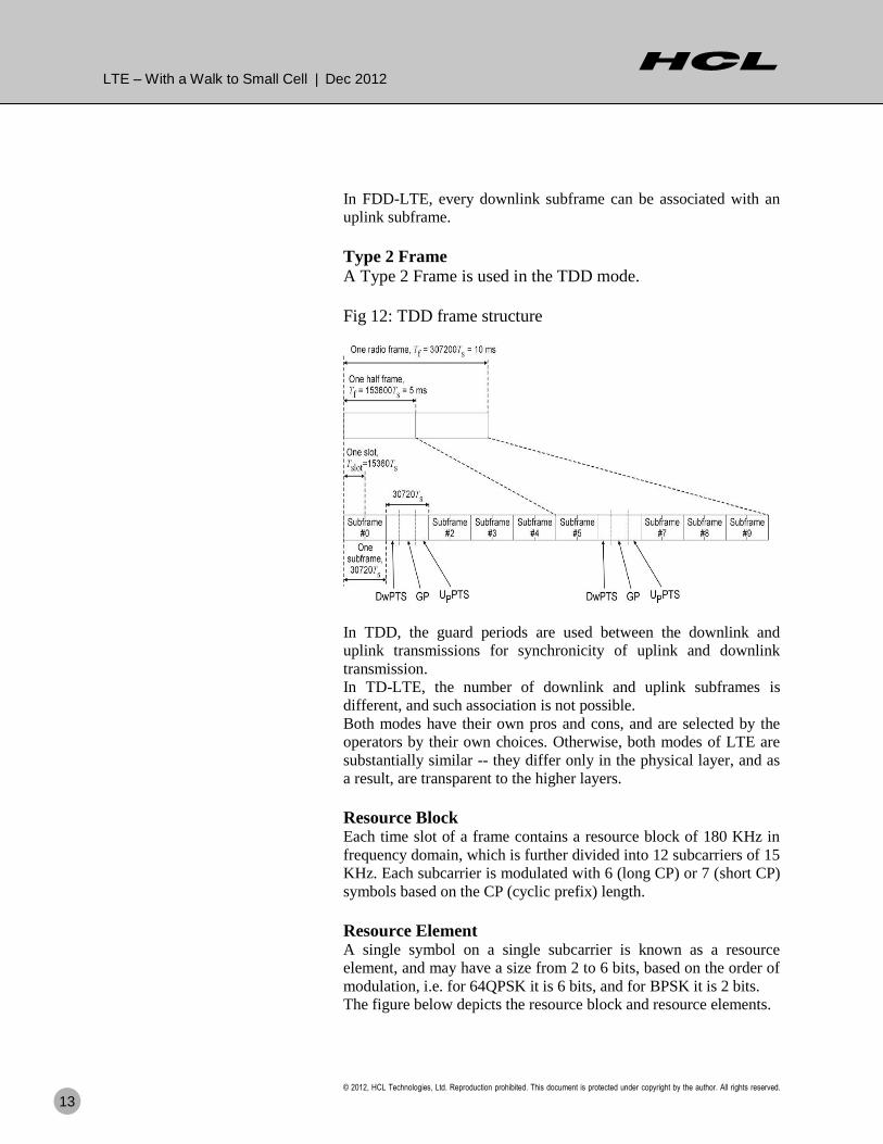
In FDD-LTE, every downlink subframe can be associated with an
uplink subframe.
Type 2 Frame
A Type 2 Frame is used in the TDD mode.
Fig 12: TDD frame structure
In TDD, the guard periods are used between the downlink and
uplink transmissions for synchronicity of uplink and downlink
transmission.
In TD-LTE, the number of downlink and uplink subframes is
different, and such association is not possible.
Both modes have their own pros and cons, and are selected by the
operators by their own choices. Otherwise, both modes of LTE are
substantially similar -- they differ only in the physical layer, and as
a result, are transparent to the higher layers.
Resource Block Each time slot of a frame contains a resource block of 180 KHz in
frequency domain, which is further divided into 12 subcarriers of 15
KHz. Each subcarrier is modulated with 6 (long CP) or 7 (short CP)
symbols based on the CP (cyclic prefix) length.
Resource Element A single symbol on a single subcarrier is known as a resource
element, and may have a size from 2 to 6 bits, based on the order of
modulation, i.e. for 64QPSK it is 6 bits, and for BPSK it is 2 bits.
The figure below depicts the resource block and resource elements.

LTE – With a Walk to Small Cell | Dec 2012
© 2012, HCL Technologies, Ltd. Reproduction prohibited. This document is protected under copyright by the author. All rights reserved.
14
Fig 13: Resource block and resource elements
Shannon’s Law – A fundamental limit on
data capacity of a channel
Shannon's law defines the maximum rate at which error-free data
can be transmitted over a given bandwidth in the presence of noise.
It is usually expressed in this form,
C = W log2(1 + S/N )
where C is the channel capacity in bits per second, W is the
bandwidth in Hertz, and S/N is the SNR (signal-to-noise ratio).
Basically, Shannon‘s law shows the relation of the channel capacity
with the channel bandwidth and signal conditions in terms of signal-
to-noise ratio. So this is not an ultimate limit on the channel
capacity, but a relational limit, and measures can be taken to
increase the capacity by implementing certain techniques like high
order modulation schemes, spatial multiplexing, spatial diversity,
interference management, etc. Thus, a balance exists between the
data rate and the allowable error rate, signal-to-noise ratio and the
power that can be transmitted.
There are a few techniques used to overshoot the limit imposed by
Shannons‘s law, like higher order modulation and spatial diversity,
or MIMO.
Higher Order Modulation In better signal conditions, i.e. a better signal-to-noise ratio case, the
capacity of the channel could be increased through high order

LTE – With a Walk to Small Cell | Dec 2012
© 2012, HCL Technologies, Ltd. Reproduction prohibited. This document is protected under copyright by the author. All rights reserved.
15
modulation schemes like 16QPSK and 64QPSK being used in 3G
and 4G networks.
MIMO While some improvements can be made in terms of optimizing the
modulation scheme and improving the signal-to-noise ratio, these
improvements are not always easy or cheap, and they are invariably
a compromise, balancing the various factors involved. It is therefore
necessary to look at other ways of improving the data throughput for
individual channels. MIMO is one way in which wireless
communications can be improved, and as a result, it is receiving a
considerable degree of interest.
Smart antenna arrays during transmission and reception creates
diversity in an intelligent way which changes the signal
characteristics, so as to get improved signal strength, less signal-to-
noise ratio and improved channel capacity. Depending on the
multiplicity of antenna MIMO mode is generally categorized as 2*2
MIMO or 4*4 MIMO.
The two main formats for MIMO are stated below:
Spatial diversity gain: Spatial diversity used to provide
improvements in the signal-to-noise ratio, and they are characterized
by improving the reliability of the system with respect to the various
forms of fading.
Spatial multiplexing gain: This form of MIMO is used to provide
additional data capacity by utilizing the different paths to carry
additional traffic, i.e. increasing the data throughput capability.
MIMO has been recognized as a significant technology for radio
communication improvement and widely accepted in LTE advance
in advance form.
LTE Advance ITU-T has set new requirements under the term IMT-advance for
the real 4G networks, and they are pertinent to high data rates, i.e.
exactly saying 100mbps on high mobility and 1gbps on low
mobility case. 3GPP has come up with an improvement in LTE in
Release 10 and above for meeting these requirements, and even
bypassing them with features known to be LTE-advance. Apart
from achieving the technical requirements, a major reason for
aligning LTE for IMT-Advanced is that the systems conforming to
IMT advance will be candidates for future new spectrum bands that
are still to be identified, and justify LTE to be a long-term
evolution.
There are some of the main techniques used in LTE advance for
high data rates and required QOS under capacity and coverage
enhancements.

LTE – With a Walk to Small Cell | Dec 2012
© 2012, HCL Technologies, Ltd. Reproduction prohibited. This document is protected under copyright by the author. All rights reserved.
16
Carrier Aggregation Carrier aggregation is a multi-carrier multiplexing technique for
capacity enhancement. Two or more component carriers are
aggregated to provide wider transmission bandwidths up to
100MHz. However, initial LTE Advanced (3GPP Release 10) deployments will likely be limited to use of the maximum two-
component carrier for a maximum bandwidth of 40 MHz.
Contiguous and noncontiguous component carrier aggregation is
supported, which ensures the highest flexibility in spectrum usage
according to individual network operator needs.
Fig 14: carrier aggregation
LTE Release 8 allows a 100 kHz frequency raster placing the LTE
channel within the operator owned bandwidth. The 15kHz
subcarrier spacing, in combination with contiguously aggregated
component carriers, requires a 300kHz carrier spacing in order to
preserve the orthogonal characteristics in the downlink transmission
scheme.
Each component carrier is limited to a maximum of 110 resource
blocks in the frequency domain using the LTE Release 8
numerology. Further, each component carrier should be compatible
with the release8 carrier in order to support legacy LTE Release 8
terminals. However, it is not necessary for all carriers in the multi-
carrier aggregation.
Component carriers transmitted by the same eNodeB need to
provide the same cell coverage. It is envisaged that different
terminal categories will be defined, supporting simultaneous
transmission and reception of one or more component carriers.

LTE – With a Walk to Small Cell | Dec 2012
© 2012, HCL Technologies, Ltd. Reproduction prohibited. This document is protected under copyright by the author. All rights reserved.
17
Hetnet (CoMP) Coordinated multi-point (CoMP) transmission/reception is a
technique in LTE Advanced to improve the coverage of high data
rates, the cell-edge throughput, and to increase system throughput.
In most deployment scenarios, intercell intrafrequncy interference,
specifically at the cell border, degrades the system capacity.
Intercell intrafrequency interference could be turned into a useful
signal, specifically at the cell border. This requires dynamic coordination in the scheduling/transmission, including joint
transmission, from multiple geographically separate points, and also
support for joint processing of the received signals at multiple
geographically separated points.
Fig 15: Coordinated multipoint transmission and reception
Hetnet is going to be a widely-accepted approach in the access
network evolutions specifically in the radio network in the given
context, but also in general. It not only caters to capacity
enhancement, but also the efficiency of individual networks within
and across.

LTE – With a Walk to Small Cell | Dec 2012
© 2012, HCL Technologies, Ltd. Reproduction prohibited. This document is protected under copyright by the author. All rights reserved.
18
Market Trends/Challenges
Continued tussles for capacity and coverage with-
in limited spectrum There are a lot of advancements being done in terms of improving
the data capacity and coverage of radio networks through various
measures like efficient utilization of spectrum, spectrum reusability,
interference management, etc. LTE is one of such advancements
that provides high data rate with a low cost of data through adopting
frequency division multiplexing techniques like OFDMA and SC-
FDMA, and also incorporating techniques for further improvement
of data rates like high order modulation, and spatial multiplexing
techniques like adaptive antenna array, MIMO, beam formation and
adaptive automations like SON.
However, research data in the past has demonstrated the actual
capacity gained in a real world deployment has been achieved
through reusability of the spectrum. That is also endorsed by the
operator community, and this emphasizes the relevance of small cell
in the real world network deployment. As small cell deployment
provide increased cell density with the spectrum reusability and
better spectrum efficiency for the system.
The table below demonstrates the work done by Martin Cooper
(Source: Small cell forum whitepaper published in Feb 2012) shows
that the vast majority of capacity growth in the real world was
achieved by spectrum re-use through the rollout of a greater number
of cells.
Table 1: Capacity gain vs Techniques
Technique Capacity
Gain
Frequency division 5
Modulation techniques 5
Access to wider range of frequency
spectrum
25
Frequency reuse through more cell sites 1,600
This data leads to the adaptation of small cell by world leading
operators for capacity and coverage enhancement, and in
continuation of their deployment and applicability, the small cell
approach has devised a more widespread business case for
operators, as they not only enhance capacity and coverage with a
low cost of operation and management, but also offer value added
services for more revenue per bit of data.

LTE – With a Walk to Small Cell | Dec 2012
© 2012, HCL Technologies, Ltd. Reproduction prohibited. This document is protected under copyright by the author. All rights reserved.
19
The surge is like a recent operator survey by Rethink Research that
identified that shipments of small cells will exceed those of macro
base stations in 2014, and consequently, as early as the end of 2015,
the installed base of small cells will exceed that of macro base
stations. The interesting thing to be noted is that the LTE advance is being
envisaged as the technology of the future, given the fact that it is
compliant with IMT advance and suited to long-term evolution.
Small cell is going to play a fundamental role in network topology
architecture development by embracing the LTE advance feature.
The outcome will be better services for customers with required
quality or quantity of data usage, and better business for operators.
Various research data in the
past has demonstrated the
actual capacity gained in a
real world deployment has
been achieved through the
reusability of the spectrum.
That is also endorsed by the
operator community, and
throws the relevance of
small cell in the real world
network deployment.
The small cell approach has
devised a more widespread
business case for operators,
as they not only enhance
capacity and coverage with
a low cost of operation and
management, but also offer
value added services for
more revenue per bit of
data..

LTE – With a Walk to Small Cell | Dec 2012
© 2012, HCL Technologies, Ltd. Reproduction prohibited. This document is protected under copyright by the author. All rights reserved.
20
Solution
What is Small Cell Small cell is the terminology coined for the low-power transmission
cells covering a small geographical area -- as small as on order of a
home. In a better sense, it could be directly related to already
existing terminology for such cells, like femto cell, although it is
overlapping to the pico, micro and metro cells as well categorized
based on a different form factor and applicability of uses.
The immediate applicability of the small cell could be utilization as
the means by which the operator provides a low-cost solution for
better capacity and coverage in their network.
Small cell network architecture Small cell uses broadband network connectivity, provided by ISPs
through xDSL or fiber lines to home or enterprises, to connect with
the mobile core network with the necessary security arrangements.
A small cell access point, in some cases also referred to as a home
eNodeB (HeNB), connects to the mobile core (EPC) through a
gateway node, referred to as HeNB GW, over IPSec tunnels
provided over internet through a security gateway, here referred to
as SeGW.
Fig 15: Femto connectivity to mobile core
Small cell on one hand increases the capacity at the radio interface,
but is limited at the backhaul through its connectivity for data rates.
There are also other issues with small cell due to its cell size, like
handover attempts and intercell intra frequency interference, etc. For
combating these issues with small cell, technology like SON (self
organizing network) is taking an important place in small cell
eNodeB architectural design and developments.
The interesting thing to note is that the LTE advance is being envisaged as the technology of future, given the fact that it is compliant with IMT advance and suited to long-term evolution. Small cell is going to play a fundamental role in network topology architecture development by embracing the LTE advance feature.
Small cell, on one hand, can
increase the capacity at the
radio interface, but is
limited at backhaul through
its connectivity for data
rates. There are also other
issues with small cell due to
its cell size, like handover
attempts and intercell intra
frequency interference, etc.
For combating these issues
with small cell, technology
like SON (self organizing
network) is taking an
important place in small cell
eNodeB architectural design
and developments.

LTE – With a Walk to Small Cell | Dec 2012
© 2012, HCL Technologies, Ltd. Reproduction prohibited. This document is protected under copyright by the author. All rights reserved.
21
Fig 16: comprehensive stack on small cell eNodeB
A typical network diagram for small cell connectivity is shown in
the figure below.
Fig 17: Typical network diagram for small cell connectivity.

LTE – With a Walk to Small Cell | Dec 2012
© 2012, HCL Technologies, Ltd. Reproduction prohibited. This document is protected under copyright by the author. All rights reserved.
22
Applicability of small cells
The most prominent applicability of small cell was found to be in
the residential and enterprise premises for a closed environment.
Though with the vast acceptance of the technology, the small cell
concept has come out into the open environment, overlapping
various form factors, i.e. pico, micro, and metro along with various
connectivity options with the core network.
For residential use For residential uses, small cell is generally referred to as femto cell,
and connected to a core network over the broadband connection
existing in the home. They are self configured and have zero touch
manageability.
Small cell can be embraced by CPE manufacturers as well. As with
advancement of home automation and media reachability, the CPE
devices could be enhanced to mobile user accessibility through
small cell.
Since small cell typically covers only a closed geographical area
like a home, the geographical positioning of the user is known to the
network, and various policy and technical decisions can be made by
network.
Fig 18: One of the use case of residential scenario.
For Enterprise uses

LTE – With a Walk to Small Cell | Dec 2012
© 2012, HCL Technologies, Ltd. Reproduction prohibited. This document is protected under copyright by the author. All rights reserved.
23
In an enterprise scenario, a number of use cases arises from the
geographical positioning, like navigation within the enterprise,
enterprise premises related restrictions and regulations, etc.
There are few other technological enhancements, like direct
connectivity of mobile subscribers to a local enterprise network and
selective traffic to direct internet without loading the operator core
network. These enhancements have embarked upon the useful use
cases in an enterprise environment, like uses of enterprise network
services, local security policy, lifting up public regulations, creating
services like IP-PBX, etc.
In order to enable enterprise users to access services on the
enterprise LAN directly, local breakout of packet data traffic will be
an option. 3GPP standards are being developed under the term LIPA
and SIPTO connectivity [5]. This prevents the operator‘s core
network from being affected by a large volume of data traffic from
the enterprise, and may help the operator provide various
economical service models.
LTE – With a Walk to Small Cell | Dec 2012
© 2012, HCL Technologies, Ltd. Reproduction prohibited. This document is protected under copyright by the author. All rights reserved.
24
Best Practices
Value-added enhancements toward heterogeneous
networks
To fulfill the requirements of high speed applications with always-
on connectivity and low latency, there are multiple approaches
being discovered to gain in terms of cost and capacity and
improvement in operators‘ revenue. Since there are multiple
technologies available with proven credentials, the concept of
heterogeneous networks has arisen, where multiple technologies
could interwork in a coordinated or hand-off mode to fulfill the
required demand.
3GPP has also taken active steps in standardization of such
extension to non-3GPP technologies like WLAN/WiMAX in
TS23.402 and TS23.234, and also setting requirements in Rel10 for
selective traffic offloading, per the TR 23.829 referred to as LIPA
and SIPTO connectivity.
Use Of Unlicensed Spectrum The most prominent unlicensed wireless system widely in use is
Wi-Fi. The benefits it provides are a large installed base, low cost,
operator independence and familiarity to consumers and enterprises,
making it a valuable component of many operators‘ mobile data
strategies. The advanced implementations of Wi-Fi can also provide
some of these features such as managed QoS and seamless
continuity.
A combination of small cells with Wi-Fi provides licensed and
unlicensed technologies together to benefit from their technical
advantages and to take on the significant capacity challenge.
Selective Traffic Offloading LIPA and SIPTO requirements refer to traffic offloading to the local
network or internet respectively, without traversing to the mobile
core network. 3GPP is setting up requirements for such breakouts in
Rel 10. The major point in the architectural requirements are:
- Mobility management signaling between the UE and the network
is handled in the Mobile Operator's Core Network
- Session management signaling (bearer setup, etc.) for LIPA,
SIPTO traffic and traffic going through the mobile operator's Core
Network terminates in the Mobile Operator's Core Network
- Reselection of a UE's offload point for SIPTO traffic that is
geographically/topologically close to the user shall be possible
during idle mode mobility procedures.
LTE – With a Walk to Small Cell | Dec 2012
© 2012, HCL Technologies, Ltd. Reproduction prohibited. This document is protected under copyright by the author. All rights reserved.
25
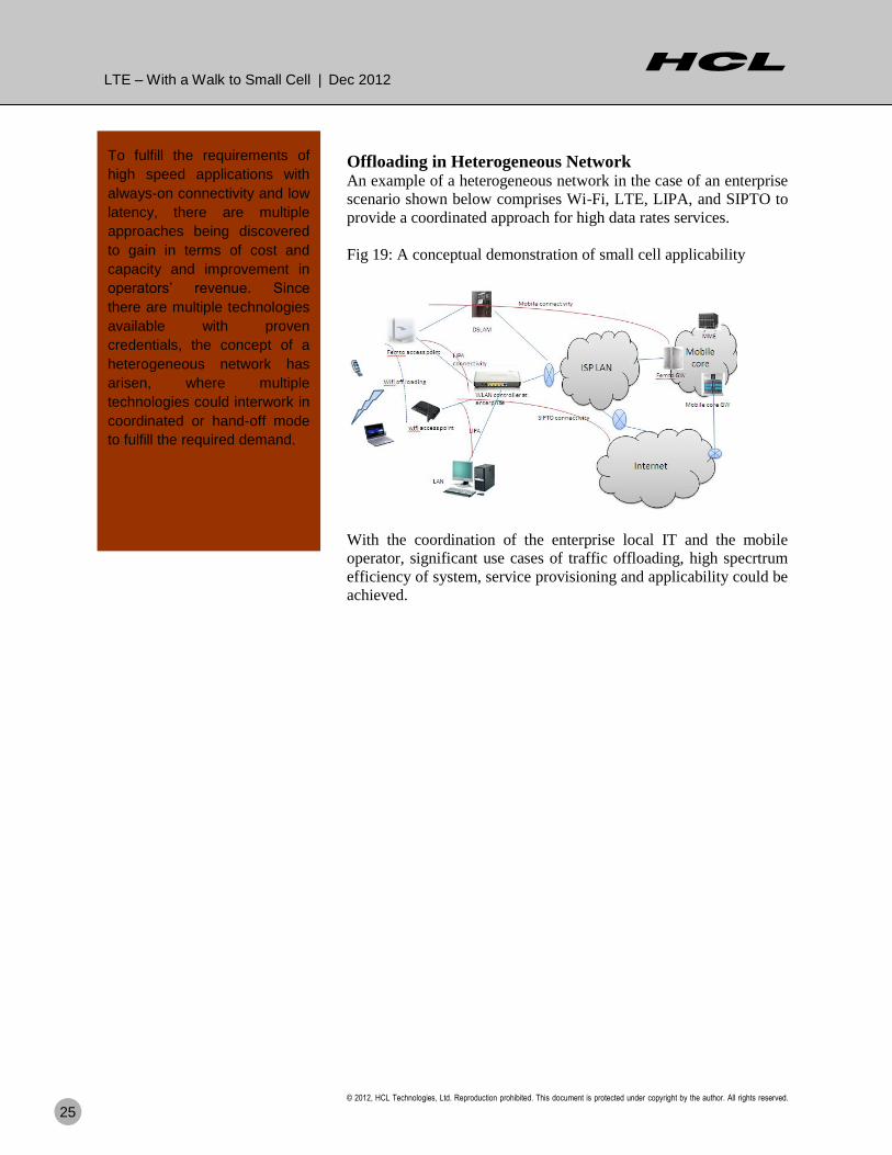
Offloading in Heterogeneous Network An example of a heterogeneous network in the case of an enterprise
scenario shown below comprises Wi-Fi, LTE, LIPA, and SIPTO to
provide a coordinated approach for high data rates services.
Fig 19: A conceptual demonstration of small cell applicability
With the coordination of the enterprise local IT and the mobile
operator, significant use cases of traffic offloading, high specrtrum
efficiency of system, service provisioning and applicability could be
achieved.
To fulfill the requirements of
high speed applications with
always-on connectivity and low
latency, there are multiple
approaches being discovered
to gain in terms of cost and
capacity and improvement in
operators’ revenue. Since
there are multiple technologies
available with proven
credentials, the concept of a
heterogeneous network has
arisen, where multiple
technologies could interwork in
coordinated or hand-off mode
to fulfill the required demand.

LTE – With a Walk to Small Cell | Dec 2012
© 2012, HCL Technologies, Ltd. Reproduction prohibited. This document is protected under copyright by the author. All rights reserved.
26
Common Issues
Limited by backhaul connectivity
Small cell capacity is limited by backhaul connectivity and depends
primarily upon the home applicability, as the connectivity depends
on home ISP connections.
QoS service flow management
QoS service flow management of traffic to small cell may require
close coordination of various network service providers like the
ISPs and TSPs.
Handover load
Since small cells are small in terms of geographical area, handover
load would be high on them, as the small cell concept arose
prominently for nomadic applications, but now, with advanced
insight into the use of small cell as network planning, it is being
used for all kinds of applications.
InterCell interference
Small cells are more prone to intercell interference of the same
frequency channels, though there are technologies like ICIC
(intercell interference co-ordinations) which are utilizing this for
improvement of signal strength.
Vendor Interoperability Vendor interoperability of small cell, not only from the OEM point
of view but also its applicability and application point of view, is
going to be a significant factor for its multifold business success.
SON is going to take a
prominent place in small cell
architectural design, as it is the
technology to combat various
technical and operational
issues.

LTE – With a Walk to Small Cell | Dec 2012
© 2012, HCL Technologies, Ltd. Reproduction prohibited. This document is protected under copyright by the author. All rights reserved.
27
Conclusion
According to ABI Research, 4.3 million small cells (including
femtocells, picocells and microcells) will be shipped in 2012, rising
to 36.8 million shipments in 2016, valued at $20.4 billion. They find
that residential and enterprise models currently dominate small cell
shipments, at 62% and
30% respectively. ABI Research‘s data suggests that by 2016, while
indoor small cells will be 94% of total shipments, outdoor small
cells will make up 64% of the revenue.
LTE advance is going to set the base for long-term evolution in the
mobile technology arena, and is going to be IMT advance compliant
for grabbing the upcoming spectrums which are not yet decided.
Small cell, being a capacity and coverage enhancement today, will
definitely take a fundamental component role of defining the
network topology and service provisioning policies in the coming
mobile technological space.
LTE advance is going to set
the base for Long term
evolution in mobile
technology arena and going
to be IMT advance
compliant for grabbing the
upcoming spectrums what
are not yet decided. Small
cell being a capacity and
coverage enhancement
today will definitely going
to take fundamental
component role of defining
the network topology and
service provisioning policies
of coming mobile
technological space.

LTE – With a Walk to Small Cell | Dec 2012
© 2012, HCL Technologies, Ltd. Reproduction prohibited. This document is protected under copyright by the author. All rights reserved.
28
References
[1] 3GPP TS 36.300 – v8.0.0, E-UTRA and E-UTRAN Overall Description, http://www.3gpp.org/ftp/Specs/archive/36%5Fseries/36.300/ [2] 3GPP TR 25.913 - v7.3.0, Requirements for EUTRA and EUTRAN, http://www.3gpp.org/ftp/Specs/archive/25%5Fseries/25.913/ [3] 3GPP TS 36.101 – v8.8.0 EUTRA- UE transmission and reception http://www.3gpp.org/ftp/Specs/archive/36%5Fseries/36.101/ [4] 3GPP TS 36.211 – v9.1.0 EUTRA-Physical channel and modulation http://www.3gpp.org/ftp/Specs/archive/36%5Fseries/36.211/ [5] 3GPP TR 23.829 – v10.0.0 LIPA-SIPTO, http://www.3gpp.org/ftp/Specs/archive/25%5Fseries/23829/ [6] 3GPP TS 23.234 – v9.0.0 3GPP WLAN interworking, http://www.3gpp.org/ftp/Specs/archive/36%5Fseries/23.234/
[7] ―small cell – what‘s the big idea?‖ Small cell forum‘s whitepapers Published in
15 Feb 2012. http://www.smallcellforum.org/resources-white-papers/
[8] ―The best LTE can be‖ Small cell forum‘s whitepapers published in May 2010.
http://www.smallcellforum.org/resources-white-papers/
[9] ―Integrated femto-wifi networks‖ Small cell forum‘s whitepapers published in
Feb 2012.
http://www.smallcellforum.org/resources-white-papers/
References for figures
Figures References
Fig 1 Reference [1]
Fig 2 conceptual
Fig 3 & 4 Reference [1]
Fig 5 & 6 conceptual
Fig 7 & 8 Reference [1]
Fig 9 conceptual
Fig 10 Reference [3]
Fig 11,12,13 Reference [4]
Fig 14,15 conceptual
Fig 16, conceptual
Fig 17 conceptual
Fig 18,19 conceptual

LTE – With a Walk to Small Cell | Dec 2012
© 2012, HCL Technologies, Ltd. Reproduction prohibited. This document is protected under copyright by the author. All rights reserved.
29
Author Info
Saurabh Verma has more than 13 years of
experience in telecom and embedded
systems development. After having worked
on various telecom network nodes and
switches development projects, he has
gained rich experience in the telecom
technological evolution path— right from
PSTN/ISDN to mobile 2G/3G. His current
focus is on LTE specifically on small cells.

Hello, I’m from HCL’s Engineering and R&D Services. We enable
technology led organizations to go to market with innovative products and
solutions. We partner with our customers in building world class products
and creating associated solution delivery ecosystems to help bring market
leadership. We develop engineering products, solutions and platforms across
Aerospace and Defense, Automotive, Consumer Electronics, Software, Online,
Industrial Manufacturing, Medical Devices, Networking & Telecom, Office
Automation, Semiconductor and Servers & Storage for our customers.
For more details contact [email protected]
Follow us on twitter: http://twitter.com/hclers
Visit our blog: http://www.hcltech.com/blogs/engineering-and-rd-services
Visit our website: http://www.hcltech.com/engineering-services/
About HCL
About HCL Technologies
HCL Technologies is a leading global IT services company, working with
clients in the areas that impact and redefine the core of their businesses. Since
its inception into the global landscape after its IPO in 1999, HCL focuses on
‗transformational outsourcing‘, underlined by innovation and value creation,
and offers integrated portfolio of services including software-led IT solutions,
remote infrastructure management, engineering and R&D services and BPO.
HCL leverages its extensive global offshore infrastructure and network of
offices in 31 countries to provide holistic, multi-service delivery in key
industry verticals including Financial Services, Manufacturing, Consumer
Services, Public Services and Healthcare. HCL takes pride in its philosophy of
'Employees First, Customers Second' which empowers our 85,335
transformers to create a real value for the customers. HCL Technologies, along
with its subsidiaries, has reported consolidated revenues of US$ 4.3 billion
(Rs. 22,417 crores), as on 30th September 2012
For more information, please visit www.hcltech.com
About HCL Enterprise
HCL is a $6.2 billion leading global technology and IT enterprise comprising
two companies listed in India - HCL Technologies and HCL Infosystems.
Founded in 1976, HCL is one of India's original IT garage start-ups. A pioneer
of modern computing, HCL is a global transformational enterprise today. Its
range of offerings includes product engineering, custom & package
applications, BPO, IT infrastructure services, IT hardware, systems
integration, and distribution of information and communications technology
(ICT) products across a wide range of focused industry verticals. The HCL
team consists of over 90,000 professionals of diverse nationalities, who
operate from 31 countries including over 500 points of presence in India. HCL
has partnerships with several leading global 1000 firms, including leading IT
and technology firms.
For more information, please visit www.hcl.com