LTE network testbed with USRP and general purpose PCperz/swtbwr2/2013/slides/Ruttik.pdf · EECRT2...
27
LTE network testbed with USRP and general purpose PC EECRT2 Project Kalle Ruttik Contributions by: G.M. Crespo,J. Kerttula, C. Guo, Y. Beyene, N. Malm 27.11.2013 EECRT2 Department of Communications and Networking Aalto, School of Electrical Engineering
Transcript of LTE network testbed with USRP and general purpose PCperz/swtbwr2/2013/slides/Ruttik.pdf · EECRT2...

LTE network testbed with USRP and general purpose PC
EECRT2 Project
Kalle Ruttik Contributions by: G.M. Crespo,J. Kerttula, C. Guo, Y. Beyene, N. Malm
27.11.2013 EECRT2
Department of Communications and Networking Aalto, School of Electrical Engineering

EECRT2 Cognitive Radio test-bed
Purpose Project creates a “living lab” cognitive radio test-bed
– Living lab: Transmission of the real application data over the air interface
– Test-bed is a realistic radio network – Test-bed is designed for investigating RRM algorithms
• Test-bed used in – TEKES EECRT project – One of METIS official test-beds

Test-bed general properties
• Composed of 24 USRP nodes – USRP N200+SBX: 0.4 – 4.4 GHz – License to transmit in 620 – 650 MHz
• Implementation of TDD-LTE type PHY in software – BB processing in C++ – RRM in Python
• Currently BB and RRM not combined
• Implementation of BS and UE units – Two-directional TDD communication
• Currently under the test – Can address users – Can allocate resource blocks

SDR implementation

Software platform operates as a radio system simulator
MAC scheduler BB
RRM Data
Buffer
MAC scheduler BB
RRM Data
Buffer
Python
C++
Buffer is a wrapper around UHD driver - It hides synchronization related issues from the rest of the code - Handles TDD direction switching
IP switch

Operates as HW in a loop simulator
MAC scheduler BB
RRM
USRP
Data
Buffer
MAC scheduler BB
RRM
USRP
Data
Buffer
Python
C++
Buffer is written as a wrapper around UHD driver - It hides synchronization related issues from the rest of the code - Handles TDD direction switching

RF AD/DA
RF AD/DA
Software RAN in VM
• Implementation of TDD LTE physical layer in software – Can run Radio Access processing in virtual machine (VM) – Separation of BB processing and sending data to RF – Can be used in servers with remote radio heads
Host OS
VM OS
BB
VM OS
BB
VM OS
BB
RF AD/DA

Software architecture
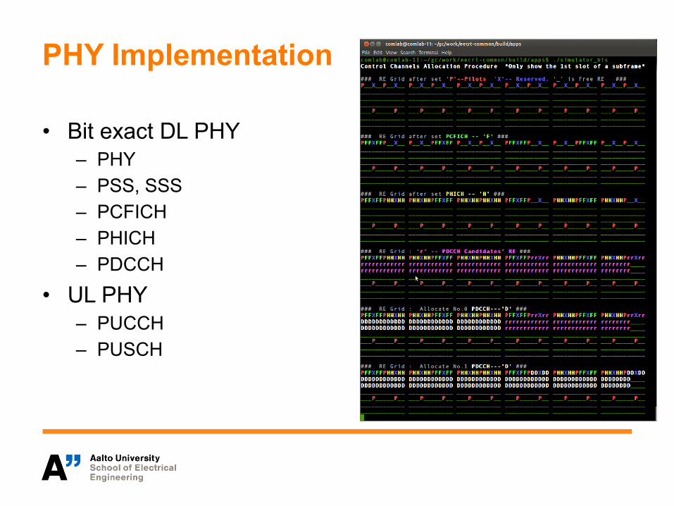
PHY Implementation
• Bit exact DL PHY – PHY – PSS, SSS – PCFICH – PHICH – PDCCH
• UL PHY – PUCCH – PUSCH

SDR with multiple USRP units
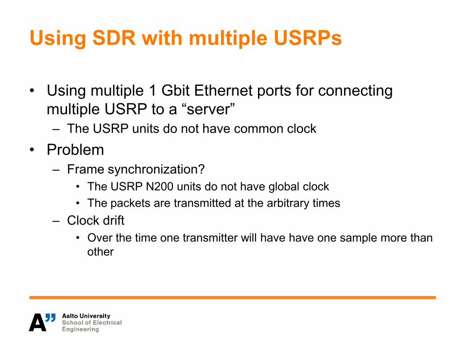
Using SDR with multiple USRPs
• Using multiple 1 Gbit Ethernet ports for connecting multiple USRP to a “server” – The USRP units do not have common clock
• Problem – Frame synchronization?
• The USRP N200 units do not have global clock • The packets are transmitted at the arbitrary times
– Clock drift • Over the time one transmitter will have have one sample more than
other

Synchronizing multiple transmitters
• Use software for synchronizing the transmitters – 2 Tx and 1 Rx connected to same computer – Rx receives both TX signals and computes correction factor – The clocks of transmitters are continuously adjusted by
adjusting the samples
• Initial calibration (synchronization) – Setting the frames to start at the same time – Use different PSS sequences
• Tracking – Keeping the transmitters synchronized

N200 vs USRP-2932
• 2.5 ppm TCXO frequency reference
• 0.01 ppm w/GPSDO option
• 2.5 ppb OCXO • 0.01 ppb w/GPSDO option
• Sample rate and RF frequency both derived from the same oscillator • Can not simply shift RF frequency
• Sampling difference gives • Phase error • Different amount of samples over time

Test Rx
Tx2
Tx1

Tx Timing Mismatch Calibration
Add delay Correlator 1
Correlator 2
Timing delay estimation
UDP/IP UDP/IP Tracking process
Tx1 source data
Tx2 source data
Add delay
Tx process
Once the Rx work station estimates the Tx timing
mismatch from the correlators‘ outputs, it indicates the Tx which antenna must delay its
transmission by N number of samples
on off
on off

Frame synchronization
• Addressable
Initial frame location Frame starting after synchro
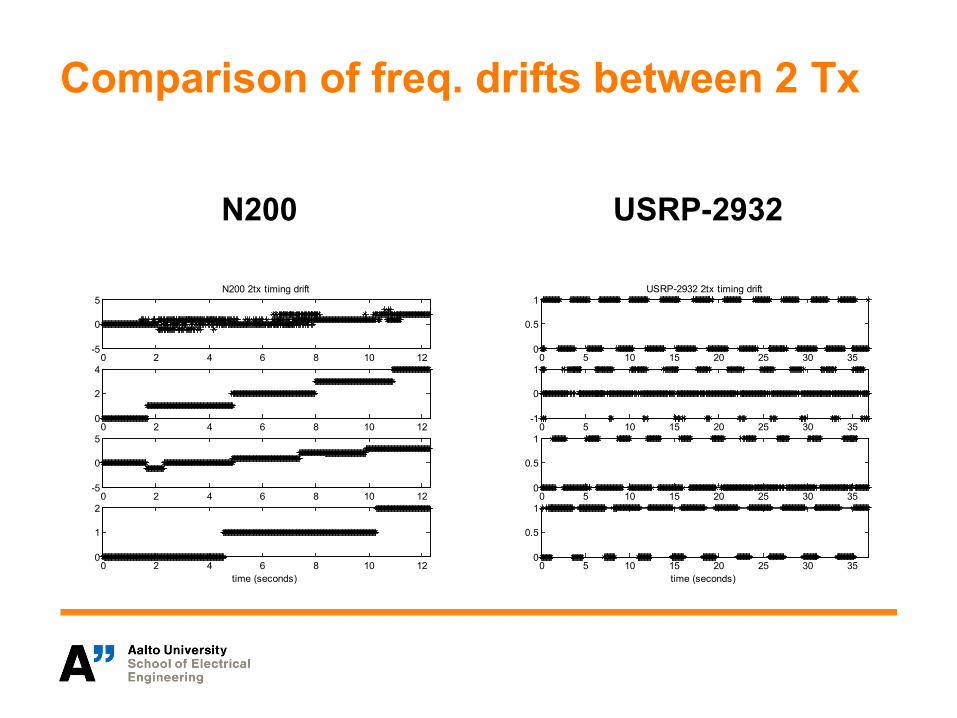
Comparison of freq. drifts between 2 Tx
N200 USRP-2932
0 5 10 15 20 25 30 350
0.5
1USRP-2932 2tx timing drift
0 5 10 15 20 25 30 35-1
0
1
0 5 10 15 20 25 30 350
0.5
1
0 5 10 15 20 25 30 350
0.5
1
time (seconds)
0 2 4 6 8 10 12-5
0
5N200 2tx timing drift
0 2 4 6 8 10 120
2
4
0 2 4 6 8 10 12-5
0
5
0 2 4 6 8 10 120
1
2
time (seconds)

Histogram of the frequency drifts 10 s. and one LTE symbol
N200 USRP-2932
0 1 2 3 4 5 6
x 10-6
0
0.2
0.4
0.6
0.8
Phase (radians)
USRP NI2932
1 20
0.2
0.4
0.6
0.8
Samples in 10 s
Mean = 1.6111 Std = 0.50163
0 1 2 3 4 5 6
x 10-5
0
0.1
0.2
0.3
0.4
Phase (radians)
N200
1 2 3 4 5 60
0.1
0.2
0.3
0.4
Samples in 10 s
Mean = 3.4681 Std = 1.12

Performance
• Drift between the transmitters clocks – Drift figure – Histogram of drift
• Error in one LTE OFDM symbol 66e-6 s – Histogram of symbol error

Radio link performance measurements
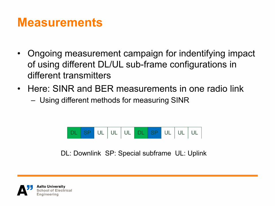
Measurements
• Ongoing measurement campaign for indentifying impact of using different DL/UL sub-frame configurations in different transmitters
• Here: SINR and BER measurements in one radio link – Using different methods for measuring SINR
DL: Downlink SP: Special subframe UL: Uplink

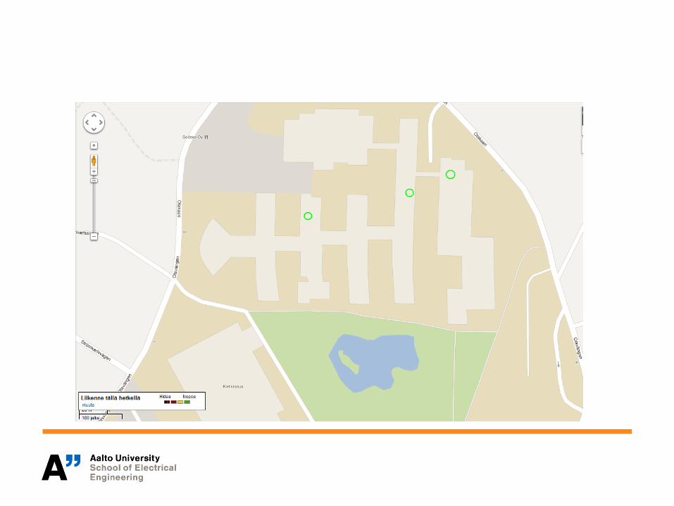
Measurement campaign
• Interference from outside Tx to inside Rx – Two TDD radio links
• one outside one inside – Measure if transmitters
• Sychronised • Nonsynchronised
– Performance is measured as SINR and BER in radio links • Performance is measured per
sub-frame
• Currently the measurement campaign is going on

SINR measurements
• EVM based measurement – The channel is feed with coded data – The data is received decoded and encoded – EVM is computed from difference of received data and decoded
and re-encoded data
• SINR estimation from the spectrum – Difference between the pilots based signal power estimate and
signal plus noise estimate from the resource elements with data
• RSSI • RSRQ

Estimation of signal strength at different USRP units

Measured BER on USRP-2932 at 630 mHz

Conclusions
• We have TDD LTE type BS that can operate in as server – The system allows real time operations – The USRP do not have common clock and they are
synchronized over the air
• The software system scales for testing TDD based radio network – We can measure and control interference in the designed
network