LTE: Introduction, evolution and testing
329
UMTS Long Term Evolution (LTE) technology intro + evolution measurement aspects Reiner Stuhlfauth [email protected] Training Centre Rohde & Schwarz, Germany Subject to change – Data without tolerance limits is not binding. R&S® is a registered trademark of Rohde & Schwarz GmbH & Co. KG. Trade names are trademarks of the owners. 2011 ROHDE & SCHWARZ GmbH & Co. KG Test & Measurement Division - Training Center - ROHDE & SCHWARZ GmbH reserves the copy right to all of any part of these course notes. Permission to produce, publish or copy sections or pages of these notes or to translate them must first be obtained in writing from ROHDE & SCHWARZ GmbH & Co. KG, Training Center, Mühldorfstr. 15, 81671 Munich, Germany
-
Upload
rohde-schwarz -
Category
Technology
-
view
4.142 -
download
1
Transcript of LTE: Introduction, evolution and testing

UMTS Long Term Evolution (LTE) technology intro + evolution measurement aspects
Reiner Stuhlfauth
Training Centre
Rohde & Schwarz, Germany
Subject to change – Data without tolerance limits is not binding.
R&S® is a registered trademark of Rohde & Schwarz GmbH & Co. KG. Trade names are trademarks
of the owners.
2011 ROHDE & SCHWARZ GmbH & Co. KG
Test & Measurement Division
- Training Center -
ROHDE & SCHWARZ GmbH reserves the copy right to all of any part of these course notes.
Permission to produce, publish or copy sections or pages of these notes or to translate them must first
be obtained in writing from
ROHDE & SCHWARZ GmbH & Co. KG, Training Center, Mühldorfstr. 15, 81671 Munich, Germany

November 2012 | LTE Introduction | 2
2013/2014 2009/2010
Technology evolution path
GSM/
GPRS
EDGE, 200 kHz DL: 473 kbps
UL: 473 kbps
EDGEevo DL: 1.9 Mbps
UL: 947 kbps
HSDPA, 5 MHz DL: 14.4 Mbps
UL: 2.0 Mbps
HSPA, 5 MHz DL: 14.4 Mbps
UL: 5.76 Mbps
HSPA+, R7 DL: 28.0 Mbps
UL: 11.5 Mbps
2005/2006 2007/2008 2011/2012
HSPA+, R8 DL: 42.0 Mbps
UL: 11.5 Mbps
cdma
2000
1xEV-DO, Rev. 0
1.25 MHz DL: 2.4 Mbps
UL: 153 kbps
1xEV-DO, Rev. A
1.25 MHz DL: 3.1 Mbps
UL: 1.8 Mbps
1xEV-DO, Rev. B
5.0 MHz DL: 14.7 Mbps
UL: 4.9 Mbps
HSPA+, R9 DL: 84 Mbps
UL: 23 Mbps
DO-Advanced DL: 32 Mbps and beyond
UL: 12.4 Mbps and beyond
LTE-Advanced R10 DL: 1 Gbps (low mobility)
UL: 500 Mbps
Fixed WiMAX
scalable bandwidth 1.25 … 28 MHz
typical up to 15 Mbps
Mobile WiMAX, 802.16e
Up to 20 MHz DL: 75 Mbps (2x2)
UL: 28 Mbps (1x2)
Advanced Mobile
WiMAX, 802.16m DL: up to 1 Gbps (low mobility)
UL: up to 100 Mbps
VAMOS Double Speech
Capacity
HSPA+, R10 DL: 84 Mbps
UL: 23 Mbps
LTE (4x4), R8+R9, 20MHz DL: 300 Mbps
UL: 75 Mbps
UMTS DL: 2.0 Mbps
UL: 2.0 Mbps

November 2012 | LTE Introduction | 3
Why LTE? Ensuring Long Term Competitiveness of UMTS
l LTE is the next UMTS evolution step after HSPA and HSPA+.
l LTE is also referred to as
EUTRA(N) = Evolved UMTS Terrestrial Radio Access (Network).
l Main targets of LTE:
l Peak data rates of 100 Mbps (downlink) and 50 Mbps (uplink)
l Scaleable bandwidths up to 20 MHz
l Reduced latency
l Cost efficiency
l Operation in paired (FDD) and unpaired (TDD) spectrum
November 2012 | LTE Introduction | 4
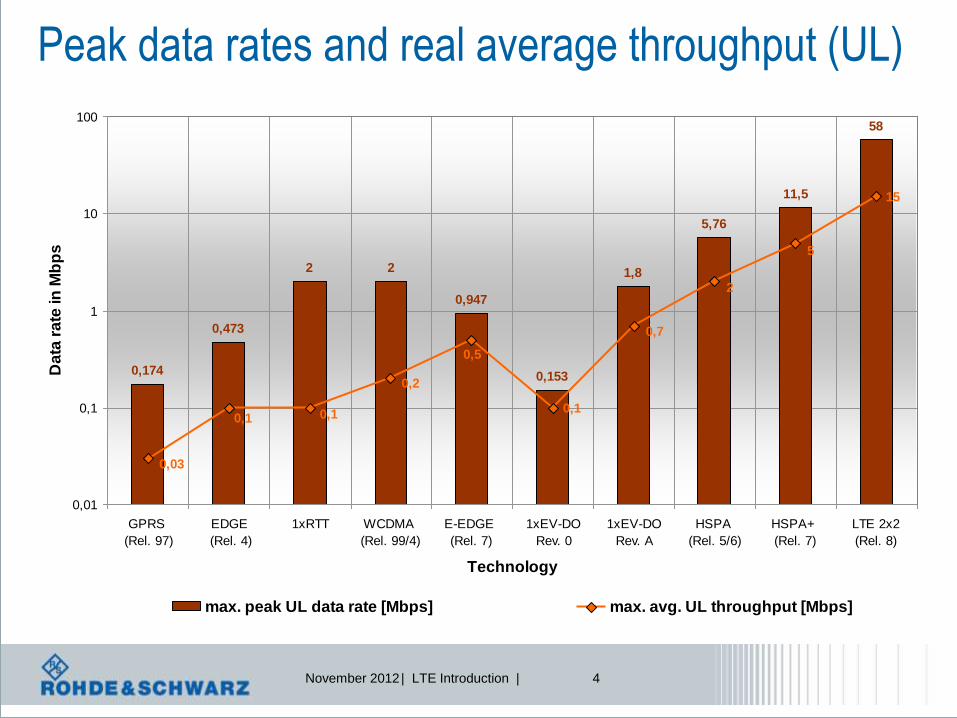
Peak data rates and real average throughput (UL)
0,174
0,473
2 2
0,947
0,153
1,8
5,76
11,5
58
0,1
15
0,1
0,03
0,1
0,2
0,5
0,7
2
5
0,01
0,1
1
10
100
GPRS
(Rel. 97)
EDGE
(Rel. 4)
1xRTT WCDMA
(Rel. 99/4)
E-EDGE
(Rel. 7)
1xEV-DO
Rev. 0
1xEV-DO
Rev. A
HSPA
(Rel. 5/6)
HSPA+
(Rel. 7)
LTE 2x2
(Rel. 8)
Technology
Da
ta r
ate
in
Mb
ps
max. peak UL data rate [Mbps] max. avg. UL throughput [Mbps]

November 2012 | LTE Introduction | 5
Comparison of network latency by technology
710
190
320
46
158
85
70
30
0
100
200
300
400
500
600
700
800
GPRS
(Rel. 97)
EDGE
(Rel. 4)
WCDMA
(Rel. 99/4)
HSDPA
(Rel. 5)
HSUPA
(Rel. 6)
E-EDGE
(Rel. 7)
HSPA+
(Rel. 7)
LTE
(Rel. 8)
Technology
2G
/ 2
.5G
la
ten
cy
0
20
40
60
80
100
120
140
160
3G
/ 3
.5G
/ 3
.9G
la
ten
cy
Total UE Air interface Node B Iub RNC Iu + core Internet

November 2012 | LTE Introduction | 6
Round Trip Time, RTT
Serving
RNC
MSC
SGSN
Iub/Iur Iu
•ACK/NACK
generation in RNC
MME/SAE Gateway
•ACK/NACK
generation in node B
Node B
eNode B
TTI
~10msec
TTI
=1msec

November 2012 | LTE Introduction | 7
Multi-RAT requirements
(GSM/EDGE, UMTS, CDMA)
MIMO multiple antenna
schemes
Timing requirements
(1 ms transm.time interval)
New radio transmission
schemes (OFDMA / SC-FDMA)
Major technical challenges in LTE
Throughput / data rate
requirements
Scheduling (shared channels,
HARQ, adaptive modulation)
System Architecture
Evolution (SAE)
FDD and
TDD mode

November 2012 | LTE Introduction | 8
Introduction to UMTS LTE: Key parameters
Frequency
Range UMTS FDD bands and UMTS TDD bands
Channel
bandwidth,
1 Resource
Block=180 kHz
1.4 MHz 3 MHz 5 MHz 10 MHz 15 MHz 20 MHz
6
Resource
Blocks
15
Resource
Blocks
25
Resource
Blocks
50
Resource
Blocks
75
Resource
Blocks
100
Resource
Blocks
Modulation
Schemes
Downlink: QPSK, 16QAM, 64QAM
Uplink: QPSK, 16QAM, 64QAM (optional for handset)
Multiple Access Downlink: OFDMA (Orthogonal Frequency Division Multiple Access)
Uplink: SC-FDMA (Single Carrier Frequency Division Multiple Access)
MIMO
technology
Downlink: Wide choice of MIMO configuration options for transmit diversity, spatial
multiplexing, and cyclic delay diversity (max. 4 antennas at base station and handset)
Uplink: Multi user collaborative MIMO
Peak Data Rate
Downlink: 150 Mbps (UE category 4, 2x2 MIMO, 20 MHz)
300 Mbps (UE category 5, 4x4 MIMO, 20 MHz)
Uplink: 75 Mbps (20 MHz)

November 2012 | LTE Introduction | 9
E-UTRA
Operating
Band
Uplink (UL) operating band
BS receive UE transmit
Downlink (DL) operating band
BS transmit UE receive Duplex Mode
FUL_low – FUL_high FDL_low – FDL_high
1 1920 MHz – 1980 MHz 2110 MHz – 2170 MHz FDD
2 1850 MHz – 1910 MHz 1930 MHz – 1990 MHz FDD
3 1710 MHz – 1785 MHz 1805 MHz – 1880 MHz FDD
4 1710 MHz – 1755 MHz 2110 MHz – 2155 MHz FDD
5 824 MHz – 849 MHz 869 MHz – 894MHz FDD
6 830 MHz – 840 MHz 875 MHz – 885 MHz FDD
7 2500 MHz – 2570 MHz 2620 MHz – 2690 MHz FDD
8 880 MHz – 915 MHz 925 MHz – 960 MHz FDD
9 1749.9 MHz – 1784.9 MHz 1844.9 MHz – 1879.9 MHz FDD
10 1710 MHz – 1770 MHz 2110 MHz – 2170 MHz FDD
11 1427.9 MHz – 1452.9 MHz 1475.9 MHz – 1500.9 MHz FDD
12 698 MHz – 716 MHz 728 MHz – 746 MHz FDD
13 777 MHz – 787 MHz 746 MHz – 756 MHz FDD
14 788 MHz – 798 MHz 758 MHz – 768 MHz FDD
17 704 MHz – 716 MHz 734 MHz – 746 MHz FDD
18 815 MHz – 830 MHz 860 MHz – 875 MHz FDD
19 830 MHz – 845 MHz 875 MHz – 890 MHz FDD
20 832 MHz - 862 MHz 791 MHz - 821 MHz FDD
21 1447.9 MHz - 1462.9 MHz 1495.9 MHz - 1510.9 MHz FDD
22 3410 MHz - 3500 MHz 3510 MHz - 3600 MHz FDD
LTE/LTE-A Frequency Bands (FDD)

November 2012 | LTE Introduction | 10
LTE/LTE-A Frequency Bands (TDD)
E-UTRA
Operating
Band
Uplink (UL) operating band
BS receive UE transmit
Downlink (DL) operating band
BS transmit UE receive Duplex Mode
FUL_low – FUL_high FDL_low – FDL_high
33 1900 MHz – 1920 MHz 1900 MHz – 1920 MHz TDD
34 2010 MHz – 2025 MHz 2010 MHz – 2025 MHz TDD
35 1850 MHz – 1910 MHz 1850 MHz – 1910 MHz TDD
36 1930 MHz – 1990 MHz 1930 MHz – 1990 MHz TDD
37 1910 MHz – 1930 MHz 1910 MHz – 1930 MHz TDD
38 2570 MHz – 2620 MHz 2570 MHz – 2620 MHz TDD
39 1880 MHz – 1920 MHz 1880 MHz – 1920 MHz TDD
40 2300 MHz – 2400 MHz 2300 MHz – 2400 MHz TDD
41 3400 MHz –
3600MHz
3400 MHz –
3600MHz TDD

November 2012 | LTE Introduction | 11
l OFDM is the modulation scheme for LTE in downlink and
uplink (as reference)
l Some technical explanation about our physical base: radio
link aspects
Orthogonal Frequency Division Multiple Access
November 2012 | LTE Introduction | 12
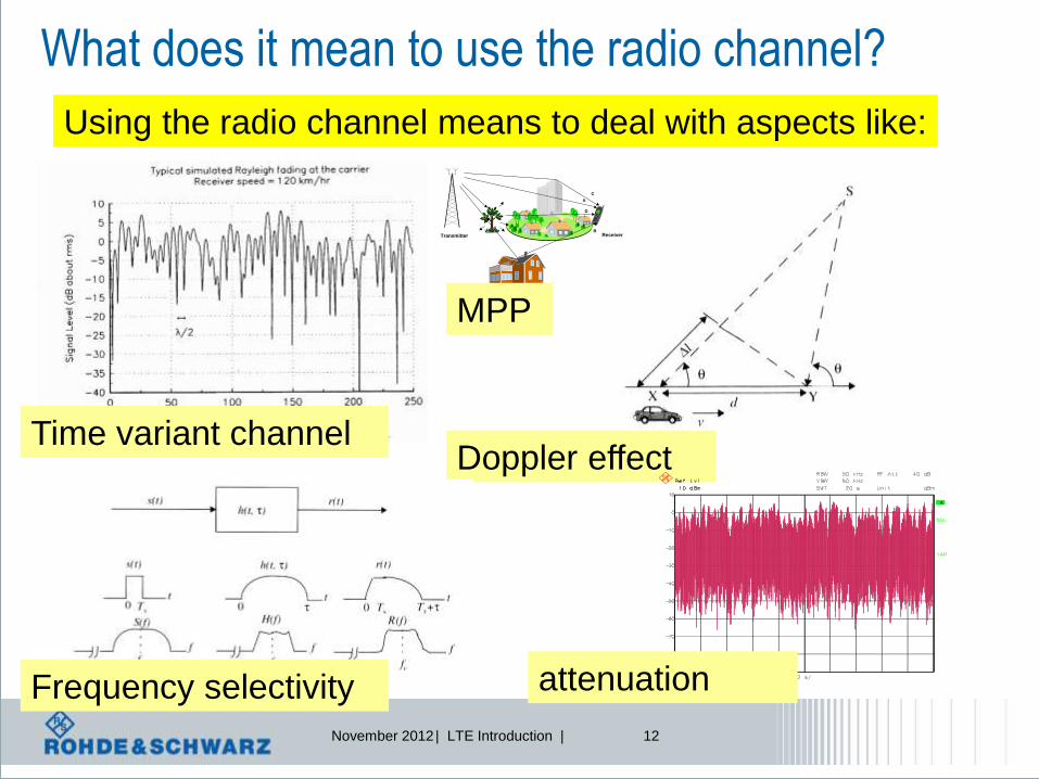
What does it mean to use the radio channel?
Using the radio channel means to deal with aspects like:
Doppler effect Time variant channel
Frequency selectivity
C
A
D
BReceiverTransmitter
MPP
attenuation
November 2012 | LTE Introduction | 13
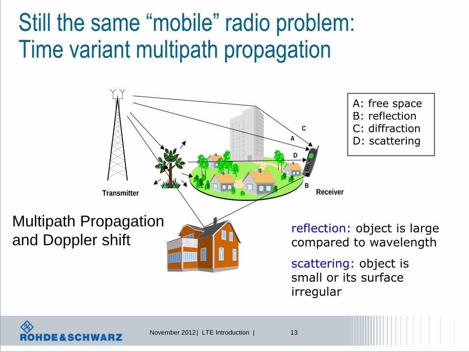
Still the same “mobile” radio problem: Time variant multipath propagation
C
A
D
BReceiverTransmitter
A: free space
B: reflection
C: diffraction
D: scattering
A: free space B: reflection C: diffraction D: scattering
reflection: object is large compared to wavelength
scattering: object is small or its surface irregular
Multipath Propagation
and Doppler shift

November 2012 | LTE Introduction | 14
Multipath channel impulse response
path delay path attenuation path phase
1
0
, i
Lj t
i i
i
h t a t e
The CIR consists of L resolvable propagation paths
delay spread
|h|²

November 2012 | LTE Introduction | 15
Radio Channel – different aspects to discuss
Bandwidth
Wideband Narrowband
Symbol duration
Short symbol
duration
Long symbol
duration
t t
Repetition rate of pilots?
Channel estimation:
Pilot mapping
or
or
Time? Frequency?
frequency distance of pilots?

November 2012 | LTE Introduction | 16
Frequency selectivity - Coherence Bandwidth
Frequency selectivity
f
power
Wideband = equalizer
Must be frequency selective
Narrowband = equalizer
Can be 1 - tap
Here: find
Math. Equation
for this curve
Here: substitute with single
Scalar factor = 1-tap
How to combat
channel influence?

November 2012 | LTE Introduction | 17
Time-Invariant Channel: Scenario
Transmitter Fixed Receiver
Fixed Scatterer
Delay Delay spread
Transmitter
Signal
t
Receiver
Signal
t
→time dispersive
ISI: Inter Symbol
Interference:
Happens, when
Delay spread >
Symbol time
Successive
symbols
will interfere Channel Impulse Response, CIR
collision

November 2012 | LTE Introduction | 18
t
f TSC
|H(f)|
Motivation: Single Carrier versus Multi Carrier
|h(t)|
t
B
l Frequency Domain
l Coherence Bandwidth Bc < Systembandwidth B
→ Frequency Selective Fading → equalization effort
l Time Domain
l Delay spread > Symboltime TSC
→ Inter-Symbol-Interference (ISI) → equalization effort
1
SC
BT
Source: Kammeyer; Nachrichtenübertragung; 3. Auflage

November 2012 | LTE Introduction | 19
|h(t)|
t
t
f
f
t
TSC |H(f)|
1
SC
BT
1
MC
Bf
N T
MC SCT N T
Motivation: Single Carrier versus Multi Carrier
B
B
|H(f)|
Source: Kammeyer; Nachrichtenübertragung; 3. Auflage
November 2012 | LTE Introduction | 20
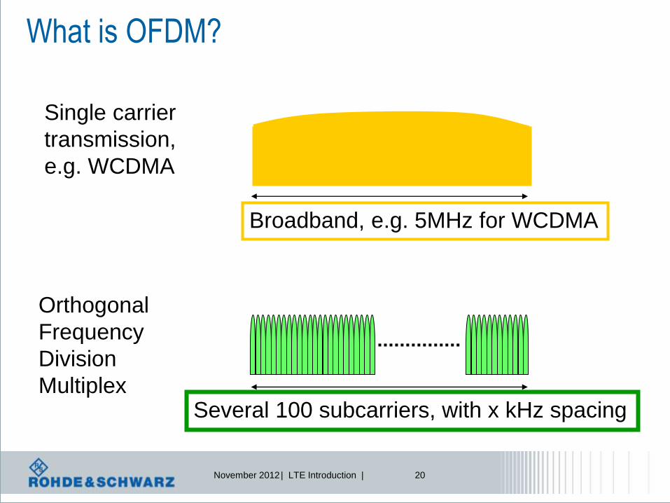
What is OFDM?
Single carrier
transmission,
e.g. WCDMA
Broadband, e.g. 5MHz for WCDMA
Orthogonal
Frequency
Division
Multiplex Several 100 subcarriers, with x kHz spacing

November 2012 | LTE Introduction | 21
Idea: Wide/Narrow band conversion
One high rate signal:
Frequency selective fading
N low rate signals:
Frequency flat fading
S/P
t / Tb t / Ts
… … …
ƒ
H(ƒ) h(τ)
τ
h(τ)
τ
„Channel
Memory“

November 2012 | LTE Introduction | 22
OFDM signal generation
00 11 10 10 01 01 11 01 …. e.g. QPSK
h*(sinjwt + cosjwt) h*(sinjwt + cosjwt)
OFDM
symbol
duration Δt
Frequency
time
=> Σ h * (sin.. + cos…)

November 2012 | LTE Introduction | 23
COFDM
X
X Ma
pp
er
+
X
X Ma
pp
er
+
....
. OFDM
symbol Σ
Data
with
FEC
overhead

November 2012 | LTE Introduction | 24
Fourier Transform, Discrete FT
;)()(
;)()(
2
2
dfefHth
dtethfH
tfj
tfj
;1
);2sin()2cos(
1
0
2
1
0
1
0
1
0
/2
N
n
N
nkj
nk
N
k
k
N
k
k
N
k
Nnkj
kn
eHN
h
N
nkhj
N
nkhehH
Fourier Transform
Discrete Fourier Transform (DFT)

November 2012 | LTE Introduction | 25
OFDM Implementation with FFT (Fast Fourier Transformation)
Receiver
Transmitter Channel
n(n)
(k) b
h(n)
r(n)
S/P
P/S
( ) ˆ b k P/S
IDF
T N
FF
T
Map
Map
Map
S/P
DF
T N
FF
T
d(0)
d(1)
Demap
Demap
Demap
s(n)
d(FFT-1)
d(FFT-1)
d(0)
d(1)
.
.
.
.
.
.

November 2012 | LTE Introduction | 26
-1 -0.5 0 0.5 1-70
-60
-50
-40
-30
-20
-10
0
10
Sx
x
f f -1
f -2
f 1
f 2
f 0
Problem of MC - FDM
Overlapp of neighbouring subcarriers
→ Inter Carrier Interference (ICI).
Solution
“Special” transmit gs(t) and receive filter gr(t) and frequencies fk allows orthogonal
subcarrier
→ Orthogonal Frequency Division Multiplex (OFDM)
Inter-Carrier-Interference (ICI)
ICI
MCS f

November 2012 | LTE Introduction | 27
Rectangular Pulse
Δt
Δf
t
f
A(f)
sin(x)/x Convolution
time frequency

November 2012 | LTE Introduction | 28
Orthogonality
Δf
Orthogonality condition: Δf = 1/Δt

November 2012 | LTE Introduction | 29
ISI and ICI due to channel
l Symbol l-1 l+1
n
h n
Delay spread
Receiver DFT
Window
fade in (ISI) fade out (ISI)

November 2012 | LTE Introduction | 30
ISI and ICI: Guard Intervall
l Symbol l-1 l+1
n
h n
Delay spread
Receiver DFT
Window
GT Delay Spread
Guard Intervall guarantees the supression of ISI!

November 2012 | LTE Introduction | 31
Receiver DFT
Window
Guard Intervall as Cyclic Prefix
l Symbol l-1 l+1
n
h n
Delay spread
GT Delay Spread
Cyclic Prefix guarantees the supression of ISI and ICI!
Cyclic Prefix

November 2012 | LTE Introduction | 32
Synchronisation
Cyclic Prefix
CP CP CP CP
:S ymbolOFDM
Metric
1ll1l
n~
Search window -

November 2012 | LTE Introduction | 33
Frequency Domain Time Domain
DL CP-OFDM signal generation chain
l OFDM signal generation is based on Inverse Fast Fourier Transform
(IFFT) operation on transmitter side:
Data
source
QAM
Modulator 1:N
N
symbol
streams
IFFT OFDM
symbols N:1 Cyclic prefix
insertion
Useful
OFDM
symbols
l On receiver side, an FFT operation will be used.

November 2012 | LTE Introduction | 34
OFDM: Pros and Cons
Pros:
scalable data rate
efficient use of the available bandwidth
robust against fading
1-tap equalization in frequency domain
Cons:
high crest factor or PAPR. Peak to average power ratio
very sensitive to phase noise, frequency- and clock-offset
guard intervals necessary (ISI, ICI) → reduced data rate

November 2012 | LTE Introduction | 35
MIMO = Multiple Input Multiple Output Antennas

November 2012 | LTE Introduction | 36
MIMO is defined by the number of Rx / Tx Antennas and not by the Mode which is supported Mode
SISO Single Input Single Output
1 1 Typical todays wireless Communication System
MISO Multiple Input Single Output
1 1
M
Transmit Diversity
l Maximum Ratio Combining (MRC)
l Matrix A also known as STC
l Space Time / Frequency Coding (STC / SFC)
SIMO Single Input Multiple Output
1 1
M
Receive Diversity
l Maximum Ratio Combining (MRC)
MIMO Multiple Input Multiple Output
1 1
M M
Definition is seen from Channel
Multiple In = Multiple Transmit Antennas
Receive / Transmit Diversity
Spatial Multiplexing (SM) also known as:
l Space Division Multiplex (SDM)
l True MIMO
l Single User MIMO (SU-MIMO)
l Matrix B
Space Division Multiple Access (SDMA) also known as:
l Multi User MIMO (MU MIMO)
l Virtual MIMO
l Collaborative MIMO
Beamforming
November 2012 | LTE Introduction | 37
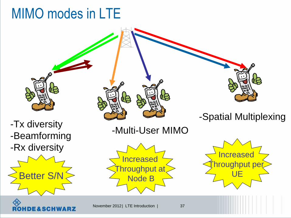
MIMO modes in LTE
-Tx diversity
-Beamforming
-Rx diversity
-Multi-User MIMO
-Spatial Multiplexing
Better S/N
Increased
Throughput at
Node B
Increased
Throughput per
UE
November 2012 | LTE Introduction | 38
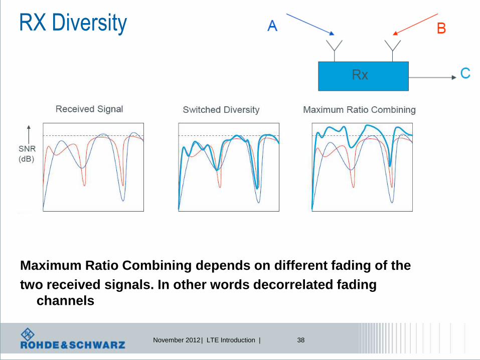
RX Diversity
Maximum Ratio Combining depends on different fading of the
two received signals. In other words decorrelated fading
channels

November 2012 | LTE Introduction | 39
TX Diversity: Space Time Coding
The same signal is transmitted at differnet
antennas
Aim: increase of S/N ratio
increase of throughput
Alamouti Coding = diversity gain
approaches
RX diversity gain with MRRC!
-> benefit for mobile communications
data
Fading on the air interface
*
12
*
21
2ss
ssS
Alamouti Coding
time
space

November 2012 | LTE Introduction | 40
MIMO Spatial Multiplexing
SISO:
Single Input
Single Output
MIMO:
Multiple Input
Multiple Output
Increasing
capacity per cell
C=B*T*ld(1+S/N)
) , min(
1
) 1 ( R T N N
i
i
i
i
N
S ld B T C ?
Higher capacity without additional spectrum!

November 2012 | LTE Introduction | 41
The MIMO promise
l Channel capacity grows linearly with antennas
l Assumptions l Perfect channel knowledge l Spatially uncorrelated fading
l Reality
l Imperfect channel knowledge l Correlation ≠ 0 and rather unknown
Max Capacity ~ min(NTX, NRX)
November 2012 | LTE Introduction | 42
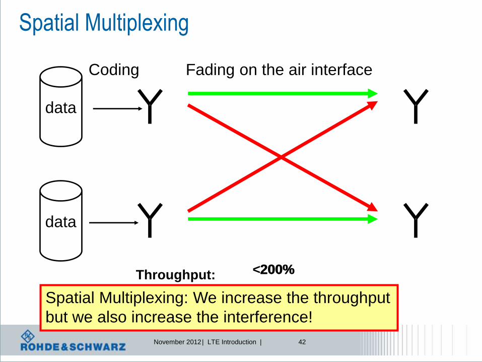
Spatial Multiplexing
Throughput:
data
Coding Fading on the air interface
data
100% 200% <200%
Spatial Multiplexing: We increase the throughput
but we also increase the interference!

November 2012 | LTE Introduction | 43
Correlation of
propagation
pathes
Transmitter Receiver
h11
h21
hMR1
h1MT
h12
h22
hMR2
h2MT
hMRMT
s1
s2
sNTx
r1
r2
rNRx
H s r
Introduction – Channel Model II
NTx
antennas NRx
antennas
Capacity ~ min(NTX, NRX) → max. possible rank!
But effective rank depends on channel, i.e. the
correlation situation of H
Rank indicator
estimates

November 2012 | LTE Introduction | 44
Spatial Multiplexing prerequisites
Decorrelation is achieved by:
l Decorrelated data content on each spatial stream
l Large antenna spacing
l Environment with a lot of scatters near the antenna
(e.g. MS or indoor operation, but not BS)
l Precoding
l Cyclic Delay Diversity
But, also possible
that decorrelation
is not given
difficult
Channel
condition
Technical
assist

November 2012 | LTE Introduction | 45
MIMO: channel interference + precoding
MIMO channel models: different ways to combat against
channel impact:
I.: Receiver cancels impact of channel
II.: Precoding by using codebook. Transmitter assists receiver in
cancellation of channel impact
III.: Precoding at transmitter side to cancel channel impact
November 2012 | LTE Introduction | 46
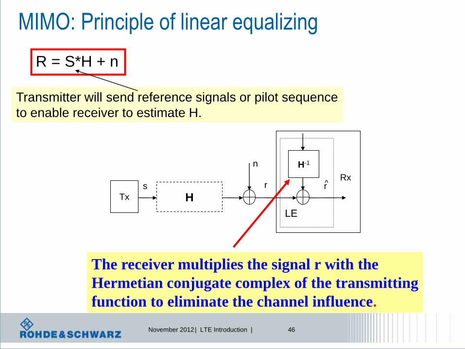
MIMO: Principle of linear equalizing
H-1
LE
s
n
r ^ r
H Tx
Rx
The receiver multiplies the signal r with the
Hermetian conjugate complex of the transmitting
function to eliminate the channel influence.
R = S*H + n
Transmitter will send reference signals or pilot sequence
to enable receiver to estimate H.

November 2012 | LTE Introduction | 47
SISO: Equalizer has to estimate 1 channel
Linear equalization – compute power increase
H = h11
h21
h12
h22
h11 H = h11
h11
h12
h21 h22
2x2 MIMO: Equalizer has to estimate 4 channels

November 2012 | LTE Introduction | 48
receiver
channel
transmitter
transmission – reception model
A H R +
noise
s r
•Modulation,
•Power
•„precoding“,
•etc.
•detection,
•estimation
•Eliminating channel
impact
•etc. Linear equalization
at receiver is not
very efficient, i.e.
noise can not be cancelled

November 2012 | LTE Introduction | 49
MIMO – work shift to transmitter
Transmitter Receiver Channel

November 2012 | LTE Introduction | 50
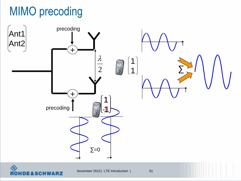
MIMO Precoding in LTE (DL) Spatial multiplexing – Code book for precoding
Codebook index
Number of layers
1 2
0
0
1
10
01
2
1
1
1
0
11
11
2
1
2
1
1
2
1
jj
11
2
1
3
1
1
2
1 -
4
j
1
2
1 -
5
j
1
2
1 -
Code book for 2 Tx:
Additional multiplication of the
layer symbols with codebook
entry
November 2012 | LTE Introduction | 51
MIMO precoding
+
+
precoding
precoding
t
t
1
1
t t
∑=0
1
-1
1
1
Ant1
Ant2
2
∑

November 2012 | LTE Introduction | 52
receiver
channel
transmitter
MIMO – codebook based precoding
A H R +
noise
s r
Precoding
codebook
Precoding Matrix Identifier, PMI
Codebook based precoding creates
some kind of „beamforming light“

November 2012 | LTE Introduction | 53
MIMO: avoid inter-channel interference – future outlook
Idea: F adapts transmitted signal to current channel conditions
Link adaptation
Transmitter
F
H +
+
Space time
receiver
xk yk
V1,k
VM,k
Feedback about H
e.g. linear precoding:
Y=H*F*S+V
S

November 2012 | LTE Introduction | 54
MAS: „Dirty Paper“ Coding – future outlook
l Multiple Antenna Signal Processing: „Known Interference“
l Is like NO interference
l Analogy to writing on „dirty paper“ by changing ink color accordingly
„Known
Interference
is No
Interference“
„Known
Interference
is No
Interference“
„Known
Interference
is No
Interference“
„Known
Interference
is No
Interference“

November 2012 | LTE Introduction | 55
Spatial Multiplexing
data
Codeword Fading on the air interface
data
Spatial Multiplexing: We like to distinguish the 2 useful
Propagation passes:
How to do that? => one idea is SVD
Codeword

November 2012 | LTE Introduction | 56
Idea of Singular Value Decomposition
know
Singular Value
Decomposition
r = H s + n
s1
s2
r1
r2
channel H
MIMO
wanted
r = D s + n ~ ~ ~
s1
s2
r1
r2
channel D
~
~ ~
~ SISO

November 2012 | LTE Introduction | 57
Singular Value Decomposition (SVD)
r = H s + n
H = U Σ (V*)T
00
0
00
00
00
3
2
1
U = [u1,...,un] eigenvectors of (H*)T H
V = [v1,...,vm] eigenvectors of H (H*)T
i isingular values
i eigenvalues of (H*)T H
~ r = (U*)T r
s = (V*)T s ~
n = (U*)T n ~
r = Σ s + n ~ ~ ~

November 2012 | LTE Introduction | 58
MIMO: Signal processing considerations MIMO transmission can be expressed as
r = Hs+n which is, using SVD = UΣVHs+n
Imagine we do the following:
1.) Precoding at the transmitter:
Instead of transmitting s, the transmitter sends s = V*s
2.) Signal processing at the receiver
Multiply the received signal with UH, r = r*UH
So after signal processing the whole signal can be expressed as:
r =UH*(UΣVHVs+n)=UHU Σ VHVs+UHn = Σs+UHn
=InTnT =InTnT
s1
s2
n2
r1
r2
U VH
σ1
σ2
Σ
n1
UH V

November 2012 | LTE Introduction | 59
MIMO: limited channel feedback
s1
s2
n2
r1
r2
U VH
σ1
σ2
Σ
n1
UH V
Transmitter Receiver
Idea 1: Rx sends feedback about full H to Tx.
-> but too complex,
-> big overhead
-> sensitive to noise and quantization effects
H
Idea 2: Tx does not need to know full H, only unitary matrix V
-> define a set of unitary matrices (codebook) and find one matrix in the codebook that
maximizes the capacity for the current channel H
-> these unitary matrices from the codebook approximate the singular vector structure
of the channel
=> Limited feedback is almost as good as ideal channel knowledge feedback

November 2012 | LTE Introduction | 60
Transmitter
Time
Delay
A1
A2
D
B
Cyclic Delay Diversity, CDD
Amp
litud
e
Delay Spread
+
+
precoding
precoding
Multipath propagation
No multipath propagation
Time
Delay

November 2012 | LTE Introduction | 61
„Open loop“ und „closed loop“ MIMO
nHWsr
nHsr
Open loop (No channel knowledge at transmitter)
Closed loop (With channel knowledge at transmitter
Adaptive Precoding matrix („Pre-equalisation“)
Feedback from receiver needed (closed loop)
Channel
Status, CSI
Rank indicator
Channel
Status, CSI
Rank indicator

November 2012 | LTE Introduction | 62
MIMO transmission modes
Transmission mode1
SISO
Transmission mode2
TX diversity Transmission mode3
Open-loop spatial
multiplexing
Transmission mode4
Closed-loop spatial
multiplexing
Transmission mode5
Multi-User MIMO
Transmission mode6
Closed-loop
spatial multiplexing,
using 1 layer
Transmission mode7
SISO, port 5
= beamforming in TDD
7 transmission
modes are
defined
Transmission mode is given by higher layer IE: AntennaInfo

November 2012 | LTE Introduction | 63
Beamforming
Adaptive Beamforming Closed loop precoded
beamforming
•Classic way
•Antenna weights to adjust beam
•Directional characteristics
•Specific antenna array geometrie
•Dedicated pilots required
•Kind of MISO with channel
knowledge at transmitter
•Precoding based on feedback
•No specific antenna
array geometrie
•Common pilots are sufficient

November 2012 | LTE Introduction | 64
Spatial multiplexing vs beamforming
Spatial multiplexing increases throughput, but looses coverage
November 2012 | LTE Introduction | 65
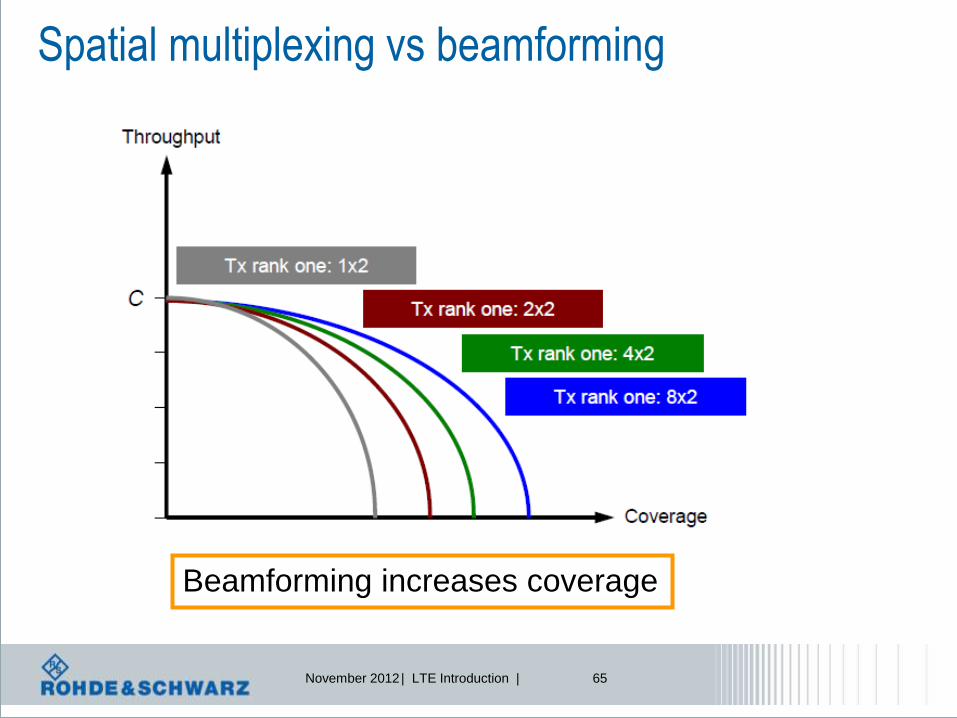
Spatial multiplexing vs beamforming
Beamforming increases coverage

November 2012 | LTE Introduction | 66
Basic OFDM parameter
2048
84.3256
115
FFT
FFTs
FFTs
N
McpsN
F
fNF
TkHzf
LTE
Data symbols
f
S/P Sub - carrier Mapping
CP insertion
Size - N FFT
Coded symbol rate= R
N TX
IFFT

November 2012 | LTE Introduction | 67
LTE Downlink: Downlink slot and (sub)frame structure
Ts = 32.522 ns
#0 #0 #1 #1 #2 #2 #3 #3 #19 #19
One slot, T slot = 15360 T s = 0.5 ms
One radio frame, T f = 307200 T s = 10 ms
#18 #18
One subframe
We talk about 1 slot, but the minimum resource is 1 subframe = 2 slots !!!!!
2048150001s T
Symbol time, or number of symbols per time slot is not fixed

November 2012 | LTE Introduction | 68
Resource block definition 1 slot = 0,5msec
12 s
ub
carr
iers
DLsymbN
ULsymbNor
Resource element
Resource block
=6 or 7 symbols
In 12 subcarriers
6 or 7,
Depending on
cyclic prefix

November 2012 | LTE Introduction | 69
time
frequency
1 resource block =
180 kHz = 12 subcarriers
1 slot = 0.5 ms =
7 OFDM symbols**
1 subframe =
1 ms= 1 TTI*=
1 resource block pair
LTE Downlink OFDMA time-frequency multiplexing
*TTI = transmission time interval
** For normal cyclic prefix duration
Subcarrier spacing = 15 kHz
QPSK, 16QAM or 64QAM modulation
UE1
UE4
UE3
UE2
UE5
UE6

November 2012 | LTE Introduction | 70
LTE: new physical channels for data and control
Physical Downlink Control Channel PDCCH: Downlink and uplink scheduling decisions
Physical Downlink Shared Channel PDSCH: Downlink data
Physical Control Format Indicator Channel PCFICH: Indicates Format of PDCCH
Physical Hybrid ARQ Indicator Channel PHICH: ACK/NACK for uplink packets
Physical Uplink Control Channel PUCCH: ACK/NACK for downlink packets, scheduling requests, channel quality info
Physical Uplink Shared Channel PUSCH: Uplink data

November 2012 | LTE Introduction | 71
LTE Downlink: FDD channel mapping example
RB Subcarrier #0

November 2012 | LTE Introduction | 72
LTE Downlink: baseband signal generation
OFDM
Mapper
OFDM signal
generationLayer
Mapper
Scrambling
Precoding
Modulation
Mapper
Modulation
Mapper
OFDM
Mapper
OFDM signal
generationScrambling
code words layers antenna ports
Avoid
constant
sequences
QPSK
16 QAM
64 QAM
For MIMO
Split into
Several
streams if
needed
Weighting
data
streams for
MIMO
1 OFDM
symbol per
stream
1 stream =
several
subcarriers,
based on
Physical
ressource
blocks
November 2012 | LTE Introduction | 73
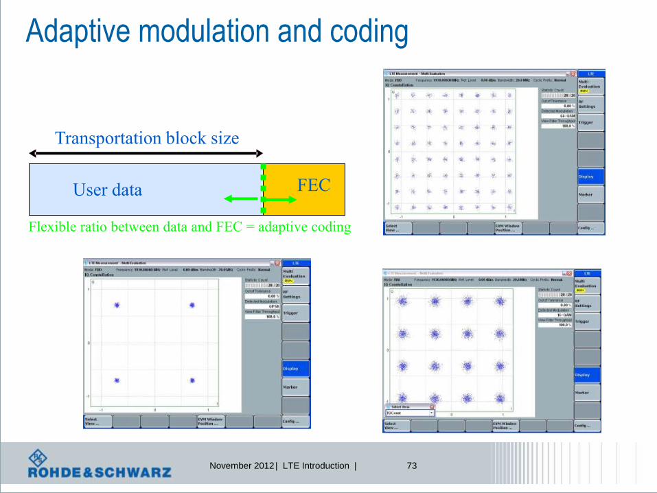
Transportation block size
FEC User data
Flexible ratio between data and FEC = adaptive coding
Adaptive modulation and coding

November 2012 | LTE Introduction | 74
Channel Coding Performance

November 2012 | LTE Introduction | 75
Automatic repeat request, latency aspects
Network UE
Round
Trip
Time
Transport block
•Transport block size = amount of
data bits (excluding redundancy!)
•TTI, Transmit Time Interval = time
duration for transmitting 1 transport
block
ACK/NACK
Immediate acknowledged or non-acknowledged
feedback of data transmission

November 2012 | LTE Introduction | 76
HARQ principle: Multitasking
t
Tx
Rx
process
Data
Δt = Round trip time
Demodulate, decode, descramble,
FFT operation, check CRC, etc.
ACK/NACK
Processing time for receiver
Rx
process
Demodulate, decode, descramble,
FFT operation, check CRC, etc.
ACK/NACK
Data Data Data Data Data Data Data Data Data
Described as 1 HARQ process

November 2012 | LTE Introduction | 77
LTE Round Trip Time RTT
t=0 t=1 t=2 t=3 t=4 t=5 t=6 t=7 t=8 t=9 t=0 t=1 t=2 t=3 t=4 t=5
PD
CC
H
UL
Data
PH
ICH
AC
K/N
AC
K
HA
RQ
Data
Downlink
Uplink
n+4 n+4 n+4
1 frame = 10 subframes
8 HARQ processes
RTT = 8 msec

November 2012 | LTE Introduction | 78
HARQ principle: Soft combining
lThis is an example of channel coding
l T i is a e am l o h n e co i g
l hi i n x m le f cha n l c ing
l Thi is an exam le of channel co ing
1st transmission with puncturing scheme P1
2nd transmission with puncturing scheme P2
Soft Combining = Σ of transmission 1 and 2
Final decoding

November 2012 | LTE Introduction | 79
Hybrid ARQ Chase Combining = identical retransmission
Turbo Encoder output (36 bits)
Rate Matching to 16 bits (Puncturing)
Chase Combining at receiver
Systematic Bits
Parity 1
Parity 2
Systematic Bits
Parity 1
Parity 2
Systematic Bits
Parity 1
Parity 2
Original Transmission Retransmission
Transmitted Bit
Punctured Bit

November 2012 | LTE Introduction | 80
Hybrid ARQ Incremental Redundancy
Turbo Encoder output (36 bits)
Rate Matching to 16 bits (Puncturing)
Incremental Redundancy Combining at receiver
Systematic Bits
Parity 1
Parity 2
Systematic Bits
Parity 1
Parity 2
Systematic Bits
Parity 1
Parity 2
Original Transmission Retransmission
Punctured Bit

November 2012 | LTE Introduction | 81
LTE Physical Layer: SC-FDMA in uplink
Single Carrier Frequency Division
Multiple Access

November 2012 | LTE Introduction | 82
LTE Uplink: How to generate an SC-FDMA signal in theory?
LTE provides QPSK,16QAM, and 64QAM as uplink modulation schemes
DFT is first applied to block of NTX modulated data symbols to transform them into
frequency domain
Sub-carrier mapping allows flexible allocation of signal to available sub-carriers
IFFT and cyclic prefix (CP) insertion as in OFDM
Each subcarrier carries a portion of superposed DFT spread data symbols
Can also be seen as “pre-coded OFDM” or “DFT-spread OFDM”
DFT Sub-carrier Mapping
CP insertion
Size-NTX Size-NFFT
Coded symbol rate= R
NTX symbols
IFFT

November 2012 | LTE Introduction | 83
LTE Uplink: How does the SC-FDMA signal look like?
In principle similar to OFDMA, BUT:
In OFDMA, each sub-carrier only carries information related to one specific symbol
In SC-FDMA, each sub-carrier contains information of ALL transmitted symbols

November 2012 | LTE Introduction | 84
time
frequency
1 resource block =
180 kHz = 12 subcarriers
1 slot = 0.5 ms =
7 SC-FDMA symbols**
1 subframe =
1 ms= 1 TTI*
LTE uplink SC-FDMA time-frequency multiplexing
*TTI = transmission time interval
** For normal cyclic prefix duration
Subcarrier spacing = 15 kHz
QPSK, 16QAM or 64QAM modulation
UE1
UE4
UE3 UE2
UE5 UE6

November 2012 | LTE Introduction | 85
LTE Uplink: baseband signal generation
Avoid
constant
sequences
QPSK
16 QAM
64 QAM
(optional)
Discrete
Fourier
Transform
Mapping on
physical
Ressource,
i.e.
subcarriers
not used for
reference
signals
1 stream =
several
subcarriers,
based on
Physical
ressource
blocks
Modulation
mapper
Transform
precoderScrambling
SC-FDMA
signal gen.
Resource
element mapper
UE specific
Scrambling code

November 2012 | LTE Introduction | 86
LTE evolution
LTE Rel. 9 features
LTE Advanced

November 2012 | LTE Introduction | 87
CoMP
In-device
co-existence Diverse Data
Application
Relaying
eICIC
enhancements
eMBMS
enhancements
LTE Release 8
FDD / TDD
DL UL
DL UL
The LTE evolution
Rel-10
Relaying
SON
enhancements
Carrier
Aggregation
MIMO 8x8 MIMO 4x4 Enhanced
SC-FDMA
eICIC
Rel-9
Rel-11
eMBMS
Positioning
Dual Layer
Beamforming
Multi carrier /
Multi-RAT
Base Stations
Home eNodeB
Self Organizing
Networks
Public Warning
System

November 2012 | LTE Introduction | 88
What are antenna ports?
l 3GPP TS 36.211(Downlink)
“An antenna port is defined such that the channel over which a symbol on the
antenna port is conveyed can be inferred from the channel over which another
symbol on the same antenna port is conveyed.”
l What does that mean?
l The UE shall demodulate a received signal – which is transmitted over a
certain antenna port – based on the channel estimation performed on the
reference signals belonging to this (same) antenna port.

November 2012 | LTE Introduction | 89
What are antenna ports?
l Consequences of the definition
l There is one sort of reference signal per antenna port
l Whenever a new sort of reference signal is introduced by 3GPP (e.g. PRS),
a new antenna port needs to be defined (e.g. Antenna Port 6)
l 3GPP defines the following antenna port / reference signal
combinations for downlink transmission:
l Port 0-3: Cell-specific Reference Signals (CS-RS)
l Port 4: MBSFN-RS
l Port 5: UE-specific Reference Signals (DM-RS): single layer (TX mode 7)
l Port 6: Positioning Reference Signals (PRS)
l Port 7-8: UE-specific Reference Signals (DM-RS): dual layer (TX mode 8)
l Port 7-14: UE specific Referene Signals for Rel. 10
l Port 15 – 22: CSI specific reference signals, channel status info in Rel. 10

November 2012 | LTE Introduction | 90
What are antenna ports?
l Mapping „Antenna Port“ to „Physical Antennas“
AP7
AP8
AP0
AP2
AP3
AP1
AP4
AP6
AP5
Antenna Port Physical Antennas
PA0
PA1
PA2
PA3
…
1
1
1
1
W5,0
W5,1
W5,2
W5,3
The way the "logical" antenna ports are mapped to the "physical" TX antennas lies
completely in the responsibility of the base station. There's no need for the base station
to tell the UE.
…
… …

November 2012 | LTE Introduction | 91
LTE antenna port definition
Antenna ports are linked to the reference signals
-> one example:
Cell Specific RS
PA - RS
PCFICH / PHICH / PDCCH
Normal CP
PUSCH or No Transmission
UE in idle mode, scans for
Antenna port 0, cell specific RS
UE in connected mode, scans
Positioning RS on antenna port 6
to locate its position

November 2012 | LTE Introduction | 92
Multimedia Broadcast Messaging Services, MBMS
Broadcast:
Public info for
everybody
Multicast:
Common info for
User after authentication
Unicast:
Private info for dedicated user

November 2012 | LTE Introduction | 93
LTE MBMS architecture

November 2012 | LTE Introduction | 94
MBMS in LTE
MBMS
GW
eNB
MCE
|
|
M1
M3 MBMS GW: MBMS Gateway
MCE: Multi-Cell/Multicast Coordination Entity
M1: user plane interface
M2: E-UTRAN internal control plane interface
M3: control plane interface between E-UTRAN and EPC
MME
|
M2
Logical architecture for MBMS

November 2012 | LTE Introduction | 95
MBSFN – MBMS Single Frequency Network
Mobile communication network
each eNode B sends individual
signals
Single Frequency Network
each eNode B sends identical
signals

November 2012 | LTE Introduction | 96
MBSFN
If network is synchronised,
Signals in downlink can be
combined

November 2012 | LTE Introduction | 97
evolved Multimedia Broadcast Multicast Services Multimedia Broadcast Single Frequency Network (MBSFN) area
l Useful if a significant number of users want to consume the same data
content at the same time in the same area!
l Same content is transmitted in a specific area is known as MBSFN area.
l Each MBSFN area has an own identity (mbsfn-AreaId 0…255) and can consists of
multiple cells; a cell can belong to more than one MBSFN area.
l MBSFN areas do not change dynamically over time.
5
2
1
3
4
6
7
9
11
12
13
10
MBSFN area 0
14
A cell can belong to
more than one MBSFN
area; in total up to 8.
MBSFN area 1
13
8
MBSFN area 255
MBSFN reserved cell.
A cell within the MBSFN
area, that does not support
MBMS transmission.
15

November 2012 | LTE Introduction | 98
eMBMS Downlink Channels
l Downlink channels related to MBMS
l MCCH Multicast Control Channel
l MTCH Multicast Traffic Channel
l MCH Multicast Channel
l PMCH Physical Multicast Channel
l MCH is transmitted over MBSFN in
specific subrames on physical layer
l MCH is a downlink only channel (no HARQ, no RLC repetitions)
l Higher Layer Forward Error Correction (see TS26.346)
l Different services (MTCHs and MCCH) can be multiplexed

November 2012 | LTE Introduction | 99
eMBMS channel mapping
Subframes 0 and 5 are not MBMS, because
of PBCH and Sync Channels
Subframes 0,4,5 and 9 are not MBMS, because
Of paging occasion can occur here

November 2012 | LTE Introduction | 100
eMBMS allocation based on SIB2 information
011010
Reminder:
Subframes
0,4,5, and 9
Are non-MBMS

November 2012 | LTE Introduction | 101
eMBMS: MCCH position according to SIB13

November 2012 | LTE Introduction | 102
LTE Release 9 Dual-layer beamforming
l 3GPP Rel-8 – Transmission Mode 7 = beamforming without
UE feedback, using UE-specific reference signal pattern,
l Estimate the position of the UE (Direction of Arrival, DoA),
l Pre-code digital baseband to direct beam at direction of arrival,
l BUT single-layer beamforming, only one codeword (TB),
l 3GPP Rel-9 – Transmission Mode 8 = beamforming with or
without UE feedback (PMI/RI) using UE-specific reference
signal pattern, but dual-layer,
l Mandatory for TDD, optional for FDD,
l 2 (new) reference signal pattern for two new antenna ports 7 and 8,
l New DCI format 2B to schedule transmission mode 8,
l Performance test in 3GPP TS 36.521 Part 1 (Rel-9) are adopted to
support testing of transmission mode 8.

November 2012 | LTE Introduction | 103
LTE Release 9 Dual-layer beamforming – Reference Symbol Details
l Cell specific antenna port 0 and antenna port 1 reference symbols
Antenna Port 0 Antenna Port 1
Antenna Port 7 Antenna Port 8
l UE specific antenna
port 7 and antenna
port 8 reference
symbols

November 2012 | LTE Introduction | 104
2 layer beamforming
Spatial multiplexing increases throughput, but looses coverage
throughput
coverage
Spatial multiplexing: increase throughput but less coverage
1 layer beamforming: increase coverage
SISO: coverage and throughput, no increase
2 layer beamforming
Increases throughput and
coverage

November 2012 | LTE Introduction | 105
Location based services
l Location Based Services“
l Products and services which need location
information
l Future Trend:
Augmented Reality

November 2012 | LTE Introduction | 106
Where is Waldo?

November 2012 | LTE Introduction | 107
Location based services
The idea is not new, … so what to discuss?
Satellite based services
Network based services
Location
controller
Who will do the measurements? The UE or the network? = „assisted“
Who will do the calculation? The UE or the network? = „based“
So what is new?
Several ideas are defined and hybrid mode is possible as well,
Various methods can be combined.

November 2012 | LTE Introduction | 108
E-UTRA supported positioning methods

November 2012 | LTE Introduction | 109
Secure User Plane
SUPL= user plane
signaling
LCS
Server (LS)
SUPL / LPP
LPPa
E-UTRA supported positioning network architecture Control plane and user plane signaling
1) SLP – SUPL Location Platform, SUPL – Secure User Plane Location 2) E-SMLC – Evolved Serving Mobile Location Center 3) GMLC – Gateway Mobile Location Center 4) LCS – Location Service 5) 3GPP TS 36.455 LTE Positioning Protocol Annex (LPPa) 6) 3GPP TS 36.355 LTE Positioning Protocol (LPP)
LTE base station
eNodeB (eNB)
E-SMLC2)
SLP1)
Mobile
Management
Entity (MME)
Serving
Gateway
(S-GW)
Packet
Gateway
(P-GW)
SLs
S1-MME
S5
LTE-capable device
User Equipment, UE
(LCS Target)
S1-U Lup
LCS4)
Client
GMLC3)
LPP
SLs
Location positioning
protocol LPP =
control plane
signaling

November 2012 | LTE Introduction | 110
E-UTRAN UE Positioning Architecture
l In contrast to GERAN and UTRAN, the E-UTRAN positioning
capabilities are intended to be forward compatible to other access
types (e.g. WLAN) and other positioning methods (e.g. RAT uplink
measurements).
l Supports user plane solutions, e.g. OMA SUPL 2.0
Source: 3GPP TS 36.305
UE = User Equipment
SUPL* = Secure User Plane Location
OMA* = Open Mobile Alliance
SET = SUPL enabled terminal
SLP = SUPL locaiton platform
E-SMLC = Evolved Serving Mobile
Location Center
MME = Mobility Management Entity
RAT = Radio Access Technology
*www.openmobilealliance.org/technical/release_program/supl_v2_0.aspx
November 2012 | LTE Introduction | 111
http://www.hindawi.com/journals/ijno/2010/812945/
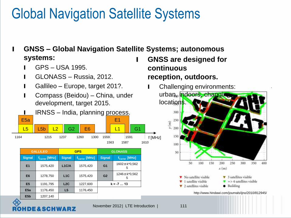
Global Navigation Satellite Systems
l GNSS – Global Navigation Satellite Systems; autonomous
systems:
l GPS – USA 1995.
l GLONASS – Russia, 2012.
l Gallileo – Europe, target 201?.
l Compass (Beidou) – China, under
development, target 2015.
l IRNSS – India, planning process.
l GNSS are designed for
continuous
reception, outdoors.
l Challenging environments:
urban, indoors, changing
locations.
GALLILEO GPS GLONASS
Signal fCarrier [MHz] Signal fCarrier [MHz] Signal fCarrier [MHz]
E1 1575,420 L1C/A 1575,420 G1 1602±k*0,562
5
E6 1278,750 L1C 1575,420 G2 1246±k*0,562
5
E5 1191,795 L2C 1227,600 k = -7 … 13
E5a 1176,450 L5 1176,450
E5b 1207,140
1164 1215 1237 1260 1300 1559 1591
1610 1587 1563
E5a
L5 L5b L2 G2
E1
L1 G1 E6
f [MHz]

November 2012 | LTE Introduction | 112
LTE Positioning Protocol (LPP) 3GPP TS 36.355
UE E-SMLC
LPP over SUPL
User plane solution
LPP over RRC
Control plane solution
SET SLP
Target
Device LPP
Location
Server Assistance data
Measurements based on reference sources*
eNB
LTE radio
signal
LPP position methods - A-GNSS Assisted Global Navigation Satellite System
- E-CID Enhanced Cell ID
- OTDOA Observed time differerence of arrival
*GNSS and LTE radio signals
SUPL enabled
Terminal
SUPL location
platform
Enhanced Serving
Mobile Location Center

November 2012 | LTE Introduction | 113
GNSS positioning methods supported l Autonomeous GNSS
l Assisted GNSS (A-GNSS)
l The network assists the UE GNSS receiver to
improve the performance in several aspects:
– Reduce UE GNSS start-up and acquisition times
– Increase UE GNSS sensitivity
– Allow UE to consume less handset power
l UE Assisted
– UE transmits GNSS measurement results to E-SMLC where the position calculation
takes place
l UE Based
– UE performs GNSS measurements and position calculation, suppported by data …
– … assisting the measurements, e.g. with reference time, visible satellite list etc.
– … providing means for position calculation, e.g. reference position, satellite ephemeris, etc.
Source: 3GPP TS 36.305

November 2012 | LTE Introduction | 114
E1
GNSS band allocations
L5 E5b L2 G2 E6 L1 G1 1164 1215 1260 1300 1559 1610
E5a
1237 1591 1563 1587
f/MHz
November 2012 | LTE Introduction | 115
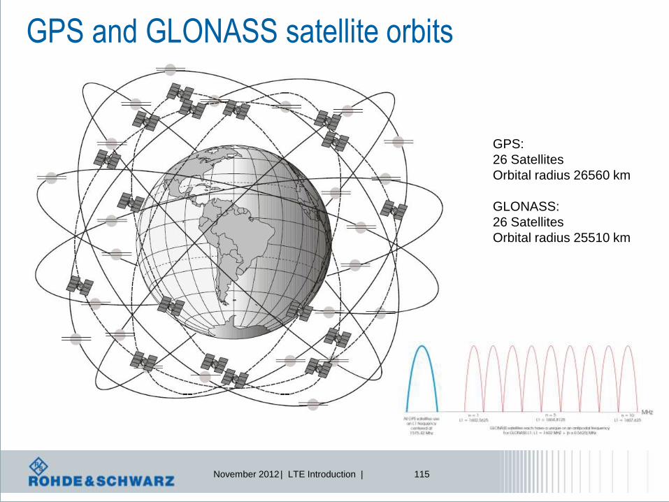
GPS and GLONASS satellite orbits
GPS:
26 Satellites
Orbital radius 26560 km
GLONASS:
26 Satellites
Orbital radius 25510 km

November 2012 | LTE Introduction | 116
Why is GNSS not sufficent?
l Global navigation satellite systems (GNSSs) have restricted
performance in certain environments
l Often less than four satellites visible: critical situation for GNSS
positioning
support required (Assisted GNSS)
alternative required (Mobile radio positioning)
Critical scenario Very critical scenario GPS Satellites visibility (Urban)
Reference [DLR]

November 2012 | LTE Introduction | 117
(A-)GNSS vs. mobile radio positioning methods
(A-)GNSS Mobile radio systems
Low bandwidth (1-2 MHz) High bandwidth (up to 20 MHz for LTE)
Very weak received signals Comparatively strong received signals
Similar received power levels from all satellites One strong signal from the serving BS,
strong interference situation
Long synchronization sequences Short synchronization sequences
Signal a-priori known due to low data rates Complete signal not a-priori known to
support high data rates, only certain pilots
Very accurate synchronization of the satellites
by atomic clocks Synchronization of the BSs not a-priori guaranteed
Line of sight (LOS) access as normal case
not suitable for urban / indoor areas
Non line of sight (NLOS) access as normal case
suitable for urban / indoor areas
3-dimensional positioning 2-dimensional positioning

November 2012 | LTE Introduction | 118
Measurements for positioning
l UE-assisted measurements.
l Reference Signal Received
Power
(RSRP) and Reference Signal
Received Quality (RSRQ).
l RSTD – Reference Signal Time
Difference.
l UE Rx–Tx time difference.
l eNB-assisted measurements.
l eNB Rx – Tx time difference.
l TADV – Timing Advance.
– For positioning Type 1 is of
relevance.
l AoA – Angle of Arrival.
l UTDOA – Uplink Time Difference
of Arrival.
RSRP, RSRQ are
measured on reference
signals of serving cell i
Serving cell i
Neighbor cell j
RSTD – Relative time difference
between a subframe received from
neighbor cell j and corresponding
subframe from serving cell i:
TSubframeRxj - TSubframeRxi
Source: see TS 36.214 Physical Layer measurements for detailed definitions
UE Rx-Tx time difference is defined
as TUE-RX – TUE-TX, where TUE-RX is the
received timing of downlink radio frame
#i from the serving cell i and TUE-TX the
transmit timing of uplink radio frame #i.
DL radio frame #i
UL radio frame #i
eNB Rx-Tx time difference is defined
as TeNB-RX – TeNB-TX, where TeNB-RX is the
received timing of uplink radio frame #i
and TeNB-TX the transmit timing of
downlink radio frame #i.
UL radio frame #i DL radio frame #i
TADV (Timing Advance)
= eNB Rx-Tx time difference + UE Rx-Tx time difference
= (TeNB-RX – TeNB-TX) + (TUE-RX – TUE-TX)

November 2012 | LTE Introduction | 119
Observed Time difference
If network is synchronised,
UE can measure time difference
Observed Time
Difference of Arrival
OTDOA

November 2012 | LTE Introduction | 120
Methods‘ overview CID E-CID (RSRP/TOA/TADV) E-CID (RSRP/TOA/TADV) [Trilateration]
E-CID (AOA) [Triangulation] Downlink / Uplink (O/U-TDOA) [Multilateration] RF Pattern matching
To be updated!!

November 2012 | LTE Introduction | 121
Cell ID
l Not new, other definition: Cell of Origin (COO).
l UE position is estimated with the knowledge of the geographical
coordinates of its serving eNB.
l Position accuracy = One whole cell .

November 2012 | LTE Introduction | 122
Enhanced-Cell ID (E-CID)
l UE positioning compared to CID is specified more
accurately using additional UE and/or E UTRAN radio
measurements:
l E-CID with distance from serving eNB position accuracy: a circle.
– Distance calculated by measuring RSRP / TOA / TADV (RTT).
l E-CID with distances from 3 eNB-s position accuracy: a point.
– Distance calculated by measuring RSRP / TOA / TADV (RTT).
l E-CID with Angels of Arrival position accuracy: a point.
– AOA are measured for at least 2, better 3 eNB‘s.
RSRP – Reference Signal Received Power
TOA – Time of Arrival
TADV – Timing Advance
RTT – Round Trip Time

November 2012 | LTE Introduction | 123
Angle of Arrival (AOA)
l AoA = Estimated angle of a UE with respect to a reference
direction (= geographical North), positive in a counter-
clockwise direction, as seen from an eNB.
l Determined at eNB antenna based
on a received UL signal (SRS).
l Measurement at eNB:
l eNB uses antenna array to estimate
direction i.e. Angle of Arrival (AOA).
l The larger the array, the more
accurate is the estimated AOA.
l eNB reports AOA to LS.
l Advantage: No synchronization
between eNB‘s.
l Drawback: costly antenna arrays.

November 2012 | LTE Introduction | 124
OTDOA – Observed Time Difference of Arrival
l UE position is estimated based on measuring TDOA of
Positioning Reference Signals (PRS) embedded into overall
DL signal received from different eNB’s.
l Each TDOA measurement describes a hyperbola (line of constant
difference 2a), the two focus points of which (F1, F2) are the two
measured eNB-s (PRS sources), and along which the UE may be
located.
l UE’s position = intersection of hyperbolas for at least 3 pairs of
eNB’s.

November 2012 | LTE Introduction | 125
Positioning Reference Signals (PRS) for OTDOA Definition
l Cell-specific reference signals (CRS) are not sufficient for
positioning, introduction of positioning reference signals
(PRS) for antenna port 6.
l SINR for synchronization
and reference signals of
neighboring cells needs to
be at least -6 dB.
l PRS is a pseudo-random
QPSK sequence similar
to CRS; PRS pattern:
l Diagonal pattern with time
varying frequency shift.
l PRS mapped around CRS to avoid collisions;
never overlaps with PDCCH; example shows
CRS mapping for usage of 4 antenna ports.
November 2012 | LTE Introduction | 126
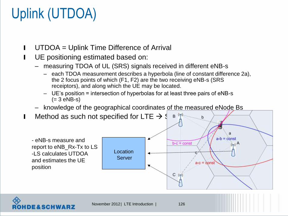
Uplink (UTDOA)
l UTDOA = Uplink Time Difference of Arrival
l UE positioning estimated based on:
– measuring TDOA of UL (SRS) signals received in different eNB-s
– each TDOA measurement describes a hyperbola (line of constant difference 2a), the 2 focus points of which (F1, F2) are the two receiving eNB-s (SRS receiptors), and along which the UE may be located.
– UE’s position = intersection of hyperbolas for at least three pairs of eNB-s (= 3 eNB-s)
– knowledge of the geographical coordinates of the measured eNode Bs
l Method as such not specified for LTE Similarity to 3G assumed
Location
Server
- eNB-s measure and
report to eNB_Rx-Tx to LS
-LS calculates UTDOA
and estimates the UE
position

November 2012 | LTE Introduction | 127
IMT-Advanced Requirements
l A high degree of commonality of functionality worldwide while
retaining the flexibility to support a wide range of services and
applications in a cost efficient manner,
l Compatibility of services within IMT and with fixed networks,
l Capability of interworking with other radio access systems,
l High quality mobile services,
l User equipment suitable for worldwide use,
l User-friendly applications, services and equipment,
l Worldwide roaming capability; and
l Enhanced peak data rates to support advanced services and
applications,
l 100 Mbit/s for high and
l 1 Gbit/s for low mobility
were established as targets for research,

November 2012 | LTE Introduction | 128
Do you Remember? Targets of ITU IMT-2000 Program (1998)
IMT-2000 The ITU vision of global wireless access
in the 21st century
Satellite
MacrocellMicrocell
UrbanIn-Building
Picocell
Global
Suburban
Basic Terminal
PDA Terminal
Audio/Visual Terminal
l Flexible and global – Full coverage and mobility at 144 kbps .. 384 kbps
– Hot spot coverage with limited mobility at 2 Mbps
– Terrestrial based radio access technologies
l The IMT-2000 family of standards now supports four different multiple
access technologies:
l FDMA, TDMA, CDMA (WCDMA) and OFDMA (since 2007)

November 2012 | LTE Introduction | 129
IMT Spectrum
Next possible spectrum
allocation at WRC 2015!
MHz
MHz
MHz
MHz

November 2012 | LTE Introduction | 130
Expected IMT-Advanced candidates
Source: TTA‘s workshop for the future of IMT-Advanced technologies, June 2008
Long
Term
Evolution
Ultra
Mobile
Broadband
Advanced
Mobile
WiMAX

November 2012 | LTE Introduction | 131
IMT – International Mobile Communication
l IMT-2000
l Was the framework for the third Generation mobile communication
systems, i.e. 3GPP-UMTS and 3GPP2-C2K
l Focus was on high performance transmission schemes:
Link Level Efficiency
l Originally created to harmonize 3G mobile systems and to increase
opportunities for worldwide interoperability, the IMT-2000 family of
standards now supports four different access technologies, including
OFDMA (WiMAX), FDMA, TDMA and CDMA (WCDMA).
l IMT-Advanced
l Basis of (really) broadband mobile communication
l Focus on System Level Efficiency (e.g. cognitive network
systems)
l Vision 2010 – 2015

November 2012 | LTE Introduction | 132
LTE-Advanced Possible technology features
Cognitive radio
methods
Enhanced MIMO
schemes for DL and UL
Interference management
methods
Relaying
technology
Cooperative
base stations
Radio network evolution
Further enhanced
MBMS
Wider bandwidth
support
November 2012 | LTE Introduction | 133
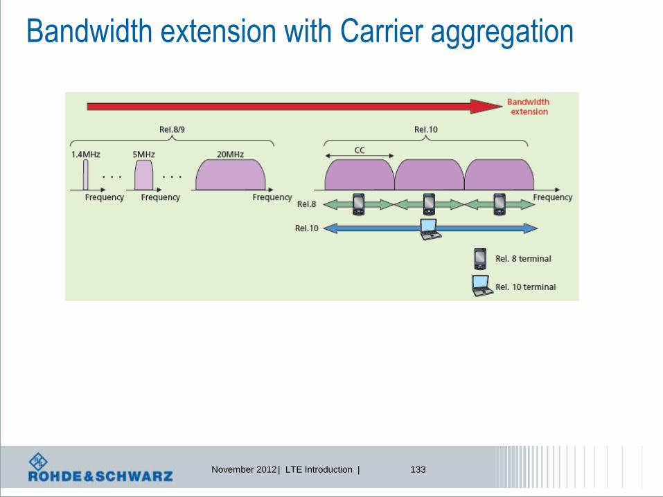
Bandwidth extension with Carrier aggregation

November 2012 | LTE Introduction | 134
LTE-Advanced Carrier Aggregation
Contiguous carrier aggregation
Non-contiguous carrier aggregation
Component carrier CC
November 2012 | LTE Introduction | 135
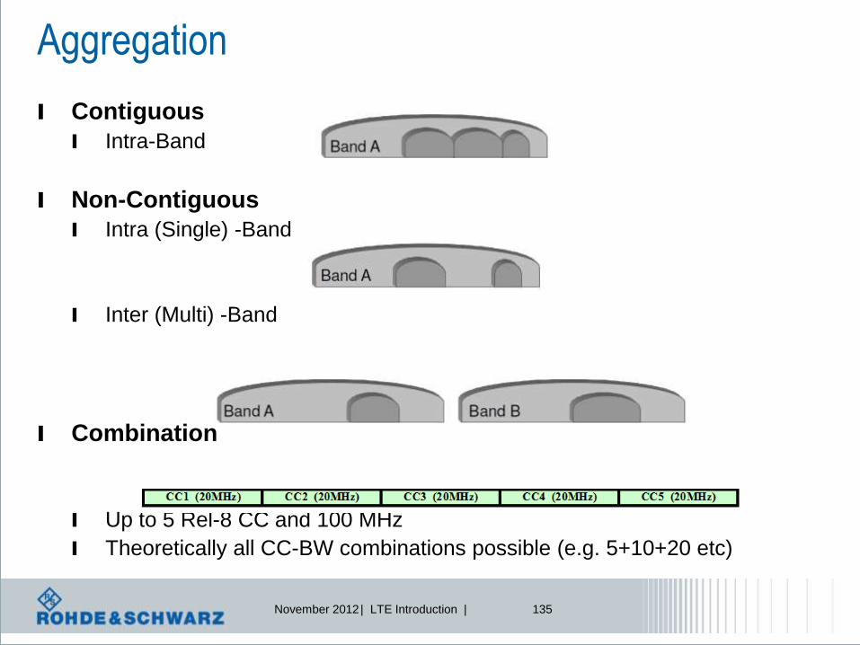
Aggregation
l Contiguous
l Intra-Band
l Non-Contiguous
l Intra (Single) -Band
l Inter (Multi) -Band
l Combination
l Up to 5 Rel-8 CC and 100 MHz
l Theoretically all CC-BW combinations possible (e.g. 5+10+20 etc)

November 2012 | LTE Introduction | 136
l Two or more component carriers are aggregated in LTE-Advanced
in order to support wider bandwidths up to 100 MHz.
l Support for contiguous and non-
contiguous component carrier
aggregation (intra-band) and
inter-band carrier aggregation. l Different bandwidths per
component carrier (CC) are possible.
l Each CC limited to a max. of 110 RB
using the 3GPP Rel-8 numerology
(max. 5 carriers, 20 MHz each).
l Motivation.
l Higher peak data rates to meet
IMT-Advanced requirements.
l NW operators: spectrum aggregation, enabling Heterogonous Networks.
Carrier aggregation (CA) General comments
Frequency band A Frequency band B
Frequency band A Frequency band B
Frequency band A Frequency band B
Intra-band contiguous
Intra-band non-contiguous
Inter-band
Component
Carrier (CC)
2012 © by Rohde&Schwarz

November 2012 | LTE Introduction | 137
Overview l Carrier Aggregation (CA)
enables to aggregate up to 5 different cells (component carriers CC), so that a maximum system bandwidth of 100 MHz can be supported (LTE-Advanced requirement).
l Each CC = Rel-8 autonomous cell
– Backwards compatibility
l CC-Set is UE specific
– Registration Primary (P)CC
– Additional BW Secondary (S)CC-s 1-4
l Network perspective
– Same single RLC-connection for one UE (independent on the CC-s)
– Many CC (starting at MAC scheduler) operating the UE
l For TDD
– Same UL/DL configuration for all CC-s
UE1 U3
UE3
UE2
UE4
UE1
UE4 UE3 UE4 U2
CC1 CC2
CC1 CC2
Cell 1 Cell 2

November 2012 | LTE Introduction | 138
Carrier aggregation (CA) General comments, cont’d. l A device capable of carrier aggregation has 1 DL primary component
carrier and 1 associated primary UL component carrier.
l Basic linkage between DL and UL is signaled in SIB Type 2.
l Configuration of primary component carrier (PCC) is UE-specific.
– Downlink: cell search / selection, system information, measurement and
mobility.
– Uplink: access procedure on PCC, control information (PUCCH) on PCC.
– Network may decide to switch PCC for a device handover procedure is
used.
l Device may have one or several secondary component carriers. Secondary
Component Carriers (SCC) added in RRC_CONNECTED mode only.
– Symmetric carrier aggregation.
– Asymmetric carrier aggregation (= Rel-10).
SCC PCC PCC SCC
Downlink Uplink
SCC SCC SCC SCC SCC SCC
PDSCH, PDCCH is optional
PDSCH and PDCCH
PUSCH only
PUSCH and PUCCH
2012 © by Rohde&Schwarz

November 2012 | LTE Introduction | 139
LTE-Advanced Carrier Aggregation – Initial Deployment
l Initial LTE-Advanced deployments will likely be limited to
the use of two component carrier.
l The below are focus scenarios identified by 3GPP RAN4.
November 2012 | LTE Introduction | 140
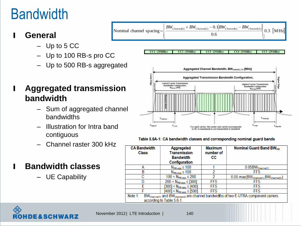
Bandwidth
l General
– Up to 5 CC
– Up to 100 RB-s pro CC
– Up to 500 RB-s aggregated
l Aggregated transmission
bandwidth
– Sum of aggregated channel
bandwidths
– Illustration for Intra band
contiguous
– Channel raster 300 kHz
l Bandwidth classes
– UE Capability
MHz3.06.0
1.0 spacingchannelNominal
)2()1()2()1(
ChannelChannelChannelChannel BWBWBWBW
November 2012 | LTE Introduction | 141
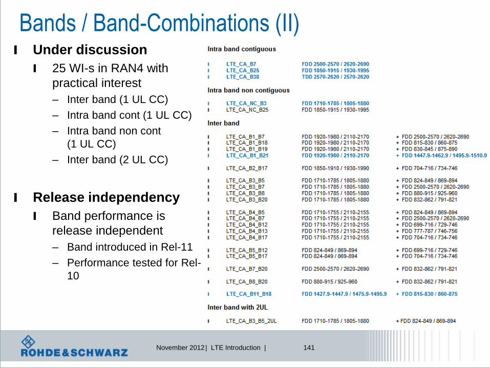
Bands / Band-Combinations (II) l Under discussion
l 25 WI-s in RAN4 with
practical interest
– Inter band (1 UL CC)
– Intra band cont (1 UL CC)
– Intra band non cont
(1 UL CC)
– Inter band (2 UL CC)
l Release independency
l Band performance is
release independent
– Band introduced in Rel-11
– Performance tested for Rel-
10
November 2012 | LTE Introduction | 142
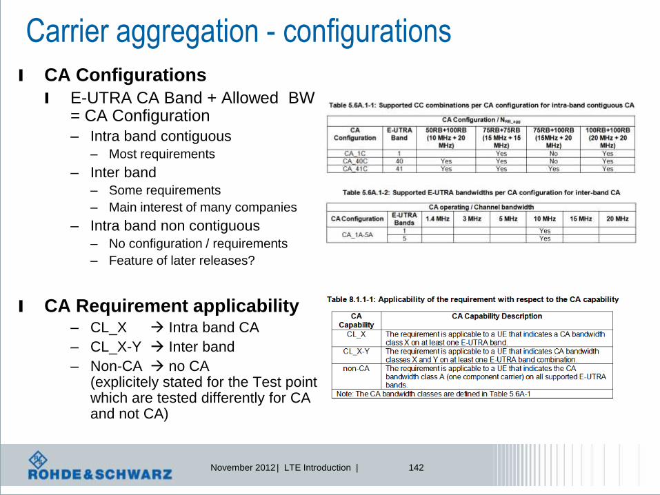
Carrier aggregation - configurations
l CA Configurations
l E-UTRA CA Band + Allowed BW = CA Configuration
– Intra band contiguous
– Most requirements
– Inter band
– Some requirements
– Main interest of many companies
– Intra band non contiguous
– No configuration / requirements
– Feature of later releases?
l CA Requirement applicability – CL_X Intra band CA
– CL_X-Y Inter band
– Non-CA no CA (explicitely stated for the Test point which are tested differently for CA and not CA)

November 2012 | LTE Introduction | 143
UE categories for Rel-10 NEW! UE categories 6…8 (DL and UL)
UE
Category
Maximum number
of DL-SCH transport
block bits received
within a TTI
Maximum number of bits
of a DL-SCH transport
block received within a TTI
Total number of
soft channel bits
Maximum number of
supported layers for
spatial multiplexing in DL
… … … … …
Category 6 301504 149776 (4 layers)
75376 (2 layers) 3654144 2 or 4
Category 7 301504 149776 (4 layers)
75376 (2 layers) 3654144 2 or 4
Category 8 2998560 299856 35982720 8
~3 Gbps peak
DL data rate
for 8x8 MIMO UE
Category
Maximum number
of UL-SCH
transport
block bits
transmitted
within a TTI
Maximum number
of bits of an UL-SCH
transport block
transmitted within a
TTI
Support
for
64Q
AM
in UL
… … … …
Category 6 51024 51024 No
Category 7 102048 51024 No
Category 8 1497760 149776 Yes
Total layer 2
buffer size
[bytes]
…
3 300 000
3 800 000
42 200 000
~1.5 Gbps peak
UL data rate, 4x4 MIMO

November 2012 | LTE Introduction | 144
Deployment scenarios
F1 F2
3) Improve coverage
l #1: Contiguous frequency aggregation – Co-located & Same coverage
– Same f
l #2: Discontiguous frequency aggregation – Co-located & Similar coverage
– Different f
l #3: Discontiguous frequency aggregation – Co-Located & Different coverage
– Different f
– Antenna direction for CC2 to cover blank spots
l #4: Remote radio heads – Not co-located
– Intelligence in central eNB, radio heads = only transmission antennas
– Cover spots with more traffic
– Is the transmission of each radio head within the cell the same?
l #5:Frequency-selective repeaters – Combination #2 & #4
– Different f
– Extend the coverage of the 2nd CC with Relays
November 2012 | LTE Introduction | 145
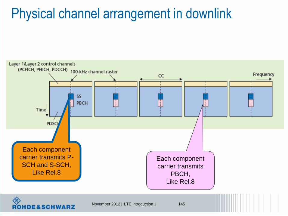
Physical channel arrangement in downlink
Each component
carrier transmits P-
SCH and S-SCH,
Like Rel.8
Each component
carrier transmits
PBCH,
Like Rel.8

November 2012 | LTE Introduction | 146
LTE-Advanced Carrier Aggregation – Scheduling
Non-Contiguous spectrum allocation Contiguous spectrum allocation
Data mod.
Mapping
Channel coding
HARQ
Data mod.
Mapping
Channel coding
HARQ
Data mod.
Mapping
Channel coding
HARQ
Data mod.
Mapping
Channel coding
HARQ
Dynamic
switching
RLC transmission buffer
[frequency in MHz]
e.g. 20 MHz
Each component
Carrier may use its
own AMC,
= modulation + coding
scheme

November 2012 | LTE Introduction | 147
Carrier Aggregation – Architecture downlink
HARQ HARQ
DL-SCH
on CC1
...
Segm.
ARQ etc
Multiplexing UE1 Multiplexing UEn
BCCH PCCH
Unicast Scheduling / Priority Handling
Logical Channels
MAC
Radio Bearers
Security Security...
CCCH
MCCH
Multiplexing
MTCH
MBMS Scheduling
PCHBCH MCH
RLC
PDCP
ROHC ROHC...
Segm.
ARQ etc...
Transport Channels
Segm.
ARQ etc
Security Security...
ROHC ROHC...
Segm.
ARQ etc...
Segm. Segm.
...
...
...
DL-SCH
on CCx
HARQ HARQ
DL-SCH
on CC1
...
DL-SCH
on CCy
In case of CA, the multi-carrier nature of the physical layer is only exposed
to the MAC layer for which one HARQ entity is required per serving cell
Multiplexing
...
Scheduling / Priority Handling
Transport Channels
MAC
RLC
PDCP
Segm.
ARQ etc
Segm.
ARQ etc
Logical Channels
ROHC ROHC
Radio Bearers
Security Security
CCCH
HARQ HARQ
UL-SCH
on CC1
...
UL-SCH
on CCz
1 UE using carrier aggregation
November 2012 | LTE Introduction | 148
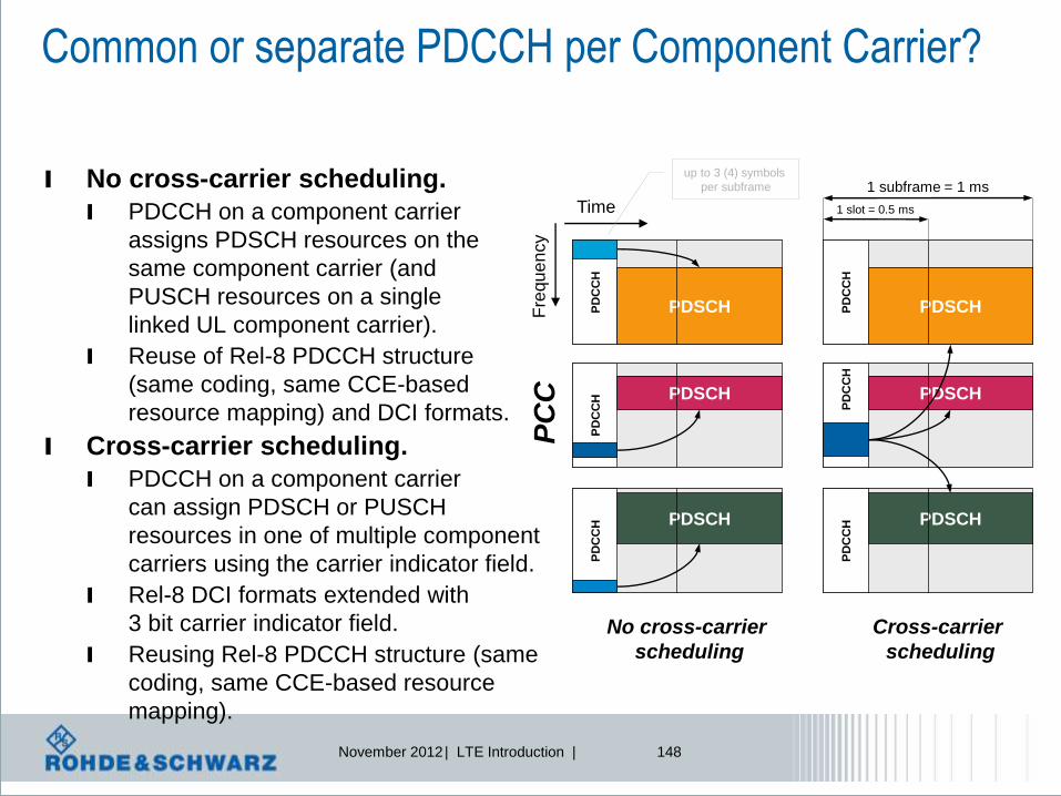
Common or separate PDCCH per Component Carrier?
No cross-carrier
scheduling
Time
Fre
qu
en
cy
PD
CC
H
PD
CC
H
PD
CC
H PDSCH
PDSCH
PDSCH
up to 3 (4) symbols
per subframe
PD
CC
H
Cross-carrier
scheduling
1 subframe = 1 ms
PD
CC
H
PD
CC
H
1 slot = 0.5 ms
PDSCH
PDSCH
PDSCH
l No cross-carrier scheduling.
l PDCCH on a component carrier
assigns PDSCH resources on the
same component carrier (and
PUSCH resources on a single
linked UL component carrier).
l Reuse of Rel-8 PDCCH structure
(same coding, same CCE-based
resource mapping) and DCI formats.
l Cross-carrier scheduling.
l PDCCH on a component carrier
can assign PDSCH or PUSCH
resources in one of multiple component
carriers using the carrier indicator field.
l Rel-8 DCI formats extended with
3 bit carrier indicator field.
l Reusing Rel-8 PDCCH structure (same
coding, same CCE-based resource
mapping).
PC
C

November 2012 | LTE Introduction | 149
Carrier aggregation: control signals + scheduling
Each CC has
its own control
channels,
like Rel.8
Femto cells:
Risk of interference!
-> main component
carrier will send
all control information.

November 2012 | LTE Introduction | 150
DCI control elements: CIF field
Carrier Indicator Field, CIF, 3bits
f f f
New field: carrier indicator field gives information,
which component carrier is valid.
=> reminder: maximum 5 component carriers!
Component carrier 1 Component carrier 2 Component carrier N

November 2012 | LTE Introduction | 151
PDSCH start field
R
R
R
PCFICH PCFICH PCFICH
Example: 1 Resource block
Of a component carrier
e.g. PCC
Primary component
carrier PDSCH start
field indicates
position
In cross-carrier scheduling,the UE does not read the PCFICH
andPDCCH on SCC, thus it has to know the start of the
PDSCH
PDCCH e.g. SCC
Secondary component
carrier

November 2012 | LTE Introduction | 152
Component Carrier – RACH configuration
Asymmetric carrier
Aggregation possible,
e.g. DL more CC than UL
Downlink
Uplink
Each CC has its own RACH All CC use same RACH preamble
Network responds on all CCs
Only 1 CC contains RACH
November 2012 | LTE Introduction | 153
Carrier Aggregation
l The transmission mode is not constrained to be the same
on all CCs scheduled for a UE
l A single UE-specific UL CC is configured semi-statically for
carrying PUCCH A/N, SR, and periodic CSI from a UE
l Frequency hopping is not supported simultaneously with
non-contiguous PUSCH resource allocation
l UCI cannot be carried on more than one PUSCH in a given
subframe.

November 2012 | LTE Introduction | 154
Carrier Aggregation
l Working assumption is confirmed that a single set of PHICH
resources is shared by all UEs (Rel-8 to Rel-10)
l If simultaneous PUCCH+PUSCH is configured and there is
at least one PUSCH transmission
l UCI can be transmitted on either PUCCH or PUSCH with a
dependency on the situation that needs to be further discussed
l All UCI mapped onto PUSCH in a given subframe gets mapped onto
a single CC irrespective of the number of PUSCH CCs
November 2012 | LTE Introduction | 155
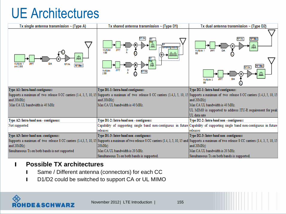
UE Architectures
l Possible TX architectures
l Same / Different antenna (connectors) for each CC
l D1/D2 could be switched to support CA or UL MIMO

November 2012 | LTE Introduction | 156
LTE–Advanced solutions from R&S R&S® SMU200 Vector Signal Generator

November 2012 | LTE Introduction | 157
Ref -20 dBm Att 5 dB
RBW 2 MHz
VBW 5 MHz
SWT 2.5 ms
Center 2.17 GHz Span 100 MHz10 MHz/
1 AP
CLRWR
A
3DB
EXT
-120
-110
-100
-90
-80
-70
-60
-50
-40
-30
-20
Date: 8.OCT.2009 14:13:24
LTE–Advanced solutions from R&S R&S® FSQ Signal Analyzer
LTE-Advanced – An introduction
A. Roessler | October 2009 | 157
20 MHz
E-UTRA carrier 2 fc,E-UTRA carrier 2 = 2205 MHz
-10 dB
20 MHz
E-UTRA carrier 2 fc,E-UTRA carrier 2 = 2135 MHz

November 2012 | LTE Introduction | 158
Enhanced MIMO schemes
l Increased number of layers:
l Up to 8x8 MIMO in downlink.
l Up to 4x4 MIMO in uplink.
l In addition the downlink reference signal structure has been
enhanced compared with LTE Release 8 by:
l Demodulation Reference signals (DM-RS) targeting PDSCH demodulation.
– UE specific, i.e. an extension to multiple layers of the concept of Release 8 UE-
specific reference signals used for beamforming.
l Reference signals targeting channel state information (CSI-RS) estimation
for CQI/PMI/RI/etc reporting when needed.
– Cell specific, sparse in the frequency and time domain and punctured into the data
region of normal subframes.

November 2012 | LTE Introduction | 159
Cell specific Reference Signals vs. DM-RS
l Demodulation-Reference signals DM-RS and data are precoded
the same way, enabling non-codebook based precoding and
enhanced multi-user beamforming.
LTE Rel.8 LTE-Advanced (Rel.10)
s1
s2
sN
........
Pre-
coding
s1
s2
sN
........
Pre-
coding
Cell specific
Reference signalsN
CRS0
DM-RSN
DM-RS0
Cell specific
reference signalsN +
Channel status information
reference signals 0
CRS0 + CSI-RS0

November 2012 | LTE Introduction | 160
Ref. signal mapping: Rel.8 vs. LTE-Advanced
l Example:
l 2 antenna ports, antenna port 0,
CSI-RS configuration 8.
l PDCCH (control) allocated in the
first 2 OFDM symbols.
l CRS sent on all RBs; DTX sent
for the CRS of 2nd antenna
port.
l DM-RS sent only for scheduled
RBs on all antennas; each set
coded differently between the
two layers.
l CSI-RS punctures Rel. 8 data;
sent periodically over allotted
REs (not more than twice per
frame)
LTE (Release 8) LTE-A (Release 10)0 1 2 3 4 5 6 0 1 2 3 4 5 6 0 1 2 3 4 5 6 0 1 2 3 4 5 6
0
x x x x 1E
x x x x SA
E
x x x x LE
R
x x x x
8
x x x x
Ex x x x S
AE
x x x x LE
R
x x x x
PDSCH PDCCH CRS DM-RS CSI-RS

November 2012 | LTE Introduction | 161
DL MIMO Extension up to 8x8
l Max number of transport blocks: 2
l Number of MCS fields
l one for each transport block
l ACK/NACK feedback
l 1 bit per transport block for evaluation
as a baseline
l Closed-loop precoding supported
l Rely on precoded dedicated
demodulation RS (decision on DL RS)
l Conclusion on the codeword-to-
layer mapping:
l DL spatial multiplexing of up to eight
layers is considered for LTE-Advanced,
l Up to 4 layers, reuse LTE codeword-to-
layer mapping,
l Above 4 layers mapping – see table
l Discussion on control signaling
details ongoing
Codeword to layer mapping for spatial multiplexing
Number
of layers
Number
of code
words
Codeword-to-layer mapping
5 2
6 2
7 2
8 2
110 layer
symbM,,i
)34()(
)24()(
)14()(
)4()(
)1()7(
)1()6(
)1()5(
)1()4(
idix
idix
idix
idix
)34()(
)24()(
)14()(
)4()(
)0()3(
)0()2(
)0()1(
)0()0(
idix
idix
idix
idix
)34()(
)24()(
)14()(
)4()(
)1()6(
)1()5(
)1()4(
)1()3(
idix
idix
idix
idix
)23()(
)13()(
)3()(
)0()2(
)0()1(
)0()0(
idix
idix
idix
)23()(
)13()(
)3()(
)1()5(
)1()4(
)1()3(
idix
idix
idix
)23()(
)13()(
)3()(
)0()2(
)0()1(
)0()0(
idix
idix
idix
)23()(
)13()(
)3()(
)1()4(
)1()3(
)1()2(
idix
idix
idix
)12()(
)2()()0()1(
)0()0(
idix
idix
32 )1(
symb
)0(
symb
layer
symb MMM
33 )1(
symb
)0(
symb
layer
symb MMM
43 )1(
symb
)0(
symb
layer
symb MMM
44 )1(
symb
)0(
symb
layer
symb MMM

November 2012 | LTE Introduction | 162
MIMO – layer and codeword
Codeword 1:
111000011101
Codeword 2:
010101010011
1 0 1
1 0 1
0 1 1
1 0 0
0 0 0
1 1 1
1 1 1
0 0 1
Codeword 1:
111000011101
Codeword 2:
010101010011
ACK ACK
ACK
Up to 8 times
the data ->
8 layers
Receiver only
Sends
2 ACK/NACKs

November 2012 | LTE Introduction | 163
Uplink MIMO Extension up to 4x4 l Rel-8 LTE.
l UEs must have 2 antennas for reception.
l But only 1 amplifier for transmission is available (costs/complexity).
l UL MIMO only as antenna switching mode (switched diversity).
l 4x4 UL SU-MIMO is needed to fulfill peak data rate requirement of
15 bps/Hz.
l Schemes are very similar to DL MIMO modes.
l UL spatial multiplexing of up to 4 layers is considered for LTE-Advanced.
l SRS enables link and SU-MIMO adaptation.
l Number of receive antennas are receiver-implementation
specific.
l At least two receive antennas is assumed on the terminal side.

November 2012 | LTE Introduction | 164
UL MIMO – signal generation in uplink
ScramblingModulation
mapper
Layer
mapperPrecoding
Resource element
mapper
SC-FDMA
signal gen.
Resource element
mapper
SC-FDMA
signal gen.Scrambling
Modulation
mapper
layerscodewords
Transform
precoder
Transform
precoder
antenna ports
Similar to Rel.8 Downlink:
Avoid
periodic bit
sequence QPSK
16-QAM
64-QAM
Up to
4 layer
DFT,
as in Rel 8,
but non-
contiguous
allocation possible

November 2012 | LTE Introduction | 165
LTE-Advanced Enhanced uplink SC-FDMA
l The uplink
transmission
scheme remains
SC-FDMA.
l The transmission of
the physical uplink
shared channel
(PUSCH) uses DFT
precoding.
l Two enhancements:
l Control-data
decoupling
l Non-contiguous
data transmission
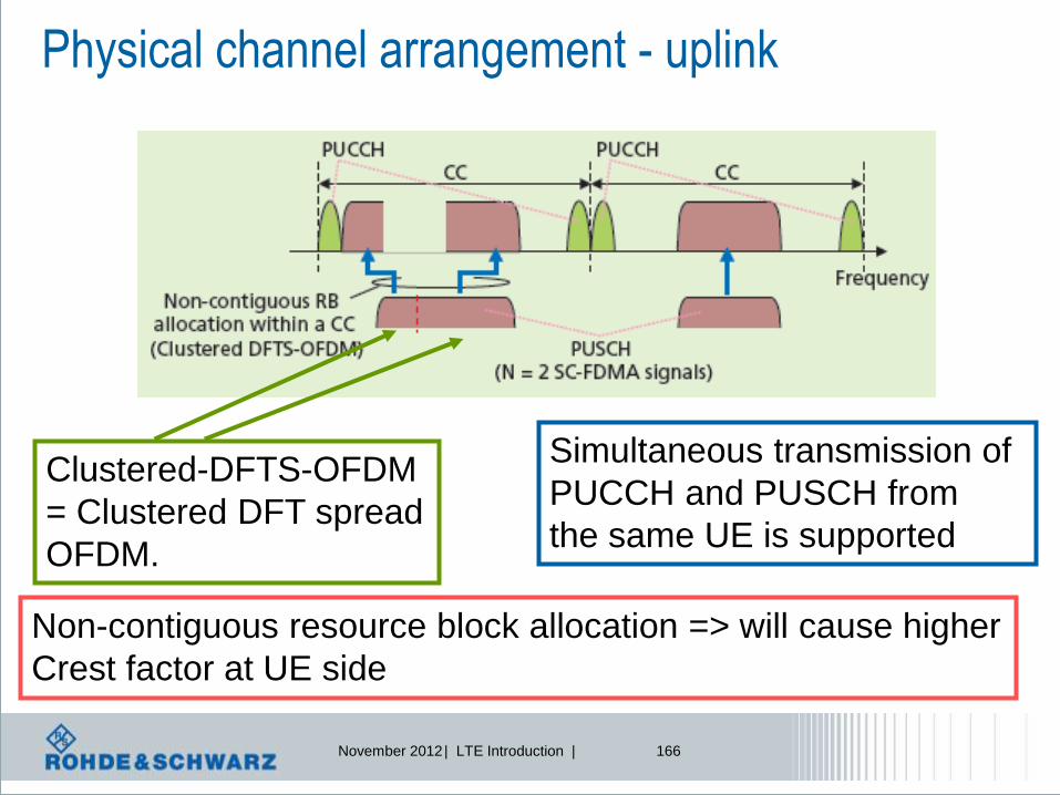
November 2012 | LTE Introduction | 166
Physical channel arrangement - uplink
Simultaneous transmission of
PUCCH and PUSCH from
the same UE is supported
Clustered-DFTS-OFDM
= Clustered DFT spread
OFDM.
Non-contiguous resource block allocation => will cause higher
Crest factor at UE side

November 2012 | LTE Introduction | 167
LTE-Advanced Enhanced uplink SC-FDMA
Due to distribution we get active subcarriers beside
non-active subcarriers: worse peak to average ratio,
e.g. Crest factor

November 2012 | LTE Introduction | 168
What are the effects of “Enhanced SC-FDMA”?
Source: http://www.3gpp.org/ftp/tsg_ran/WG4_Radio/TSGR4_54/Documents/R4-101056.zip

November 2012 | LTE Introduction | 169
f [MHz]
Simultaneous PUSCH-PUCCH transmission, multi-cluster transmission l Remember, only one UL carrier in 3GPP Release 10;
scenarios:
l Feature support is indicated by PhyLayerParameters-v1020 IE*).
PUCCH PUSCH
PUCCH and
allocated PUSCH
PUCCH and fully
allocated PUSCH
PUCCH and partially
allocated PUSCH
partially
allocated PUSCH
f [MHz]
f [MHz] f [MHz]
*) see 3GPP TS 36.331 RRC Protocol Specification
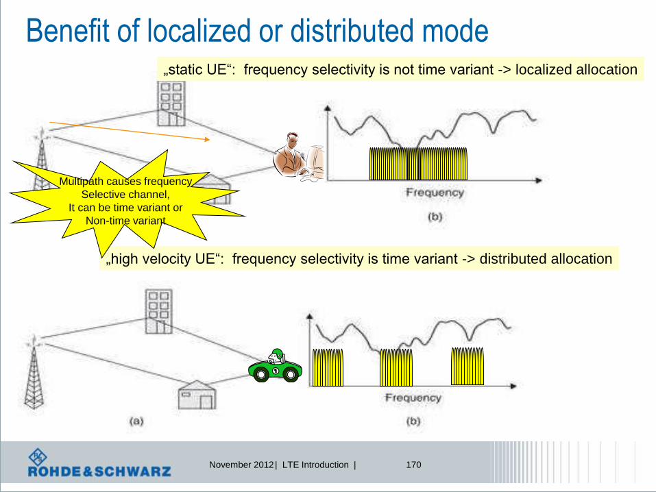
November 2012 | LTE Introduction | 170
Benefit of localized or distributed mode „static UE“: frequency selectivity is not time variant -> localized allocation
„high velocity UE“: frequency selectivity is time variant -> distributed allocation
Multipath causes frequency
Selective channel,
It can be time variant or
Non-time variant

November 2012 | LTE Introduction | 171
Significant step towards 4G: Relaying ?
Source: TTA‘s workshop for the future of IMT-Advanced technologies, June 2008

November 2012 | LTE Introduction | 172
Radio Relaying approach
Source: TTA‘s workshop for the future of IMT-Advanced technologies, June 2008
No Improvement of SNR resp. CINR
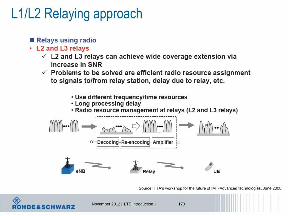
November 2012 | LTE Introduction | 173
L1/L2 Relaying approach
Source: TTA‘s workshop for the future of IMT-Advanced technologies, June 2008

November 2012 | LTE Introduction | 174
Present Thrust- Spectrum Efficiency
l FCC Measurements:- Temporal and geographical variations in the utilization of the assigned spectrum range from 15% to 85%.
Momentary snapshot of frequency spectrum allocation
Why not use this
part of the spectrum?

November 2012 | LTE Introduction | 175
ODMA – some ideas…
BTS
Mobile devices behave as
relay station
ODMA = opportunity driven multiple access

November 2012 | LTE Introduction | 176
Cooperative communication
How to implement antenna arrays in mobile handsets?
Each mobile
is user and relay 3 principles of aid:
•Amplify and forward
•Decode and forward
•Coded cooperation
Multi-access
Independent
fading paths
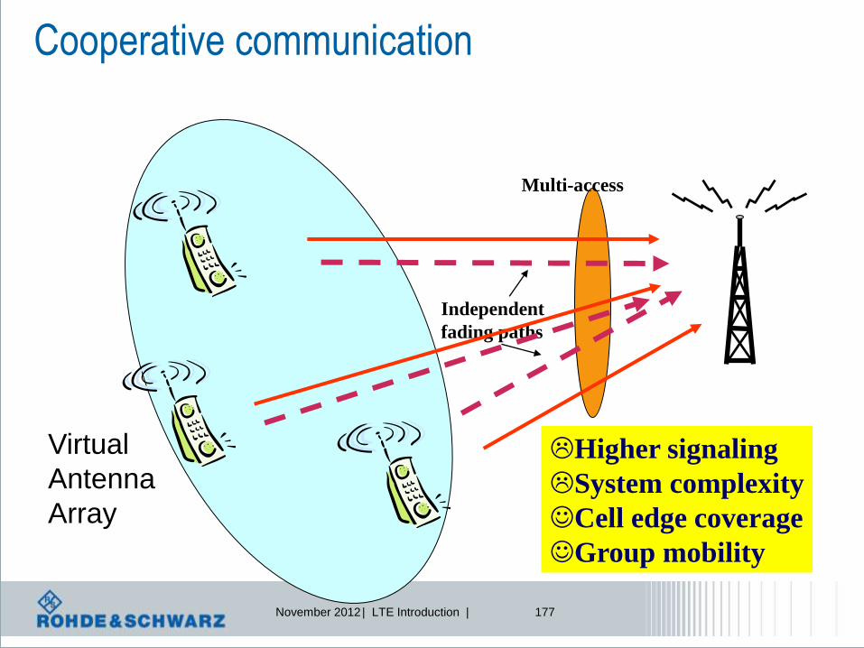
November 2012 | LTE Introduction | 177
Cooperative communication
Higher signaling
System complexity
Cell edge coverage
Group mobility
Multi-access
Independent
fading paths
Virtual
Antenna
Array

LTE, UMTS Long Term Evolution LTE measurements – from RF to application testing
Reiner Stuhlfauth
Training Centre
Rohde & Schwarz, Germany
Subject to change – Data without tolerance limits is not binding.
R&S® is a registered trademark of Rohde & Schwarz GmbH & Co. KG. Trade names are trademarks
of the owners.
2011 ROHDE & SCHWARZ GmbH & Co. KG
Test & Measurement Division
- Training Center -
This folder may be taken outside ROHDE & SCHWARZ facilities.
ROHDE & SCHWARZ GmbH reserves the copy right to all of any part of these course notes.
Permission to produce, publish or copy sections or pages of these notes or to translate them must first
be obtained in writing from
ROHDE & SCHWARZ GmbH & Co. KG, Training Center, Mühldorfstr. 15, 81671 Munich, Germany
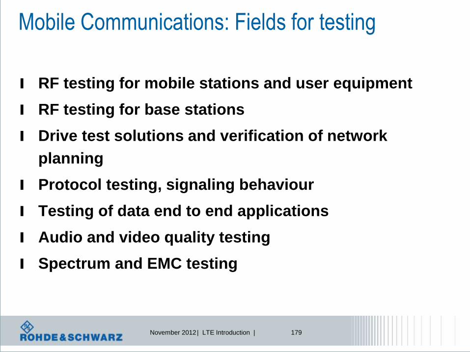
November 2012 | LTE Introduction | 179
Mobile Communications: Fields for testing
l RF testing for mobile stations and user equipment
l RF testing for base stations
l Drive test solutions and verification of network
planning
l Protocol testing, signaling behaviour
l Testing of data end to end applications
l Audio and video quality testing
l Spectrum and EMC testing
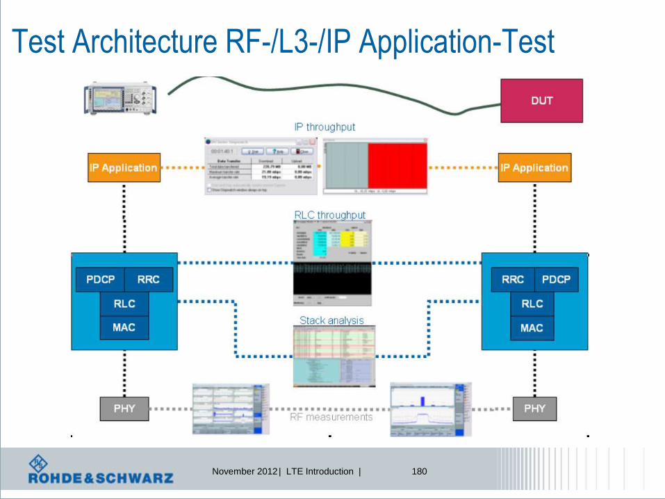
November 2012 | LTE Introduction | 180
Test Architecture RF-/L3-/IP Application-Test

November 2012 | LTE Introduction | 181
LTE measurements general aspects

November 2012 | LTE Introduction | 182
LTE RF Testing Aspects UE requirements according to 3GPP TS 36.521 Power
Maximum output power
Maximum power reduction
Additional Maximum Power
Reduction
Minimum output power
Configured Output Power
Power Control
Absolution Power Control
Relative Power Control
Aggregate Power Control
ON/OFF Power time mask
Output RF spectrum emissions
Occupied bandwidth
Out of band emissions
Spectrum emisssion mask
Additional Spectrum emission mask
Adjacent Channel Leakage Ratio
Transmit Intermodulation 36.521: User Equipment (UE) radio
transmission and reception
Transmit signal quality
Frequency error
Modulation quality, EVM
Carrier Leakage
In-Band Emission for non allocated RB
EVM equalizer spectrum flatness

November 2012 | LTE Introduction | 183
LTE RF Testing Aspects UE requirements according to 3GPP, cont.
Receiver characteristics: Reference sensitivity level
Maximum input level
Adjacent channel selectivity
Blocking characteristics
In-band Blocking
Out of band Blocking
Narrow Band Blocking
Spurious response
Intermodulation characteristics
Spurious emissions
Performance

November 2012 | LTE Introduction | 184
LTE bands and channel bandwidth E-UTRA band / channel bandwidth
E-UTRA Band 1.4 MHz 3 MHz 5 MHz 10 MHz 15 MHz 20 MHz
1 Yes Yes Yes Yes
2 Yes Yes Yes Yes Yes[1] Yes[1]
3 Yes Yes Yes Yes Yes[1] Yes[1]
4 Yes Yes Yes Yes Yes Yes
5 Yes Yes Yes Yes[1]
6 Yes Yes[1]
7 Yes Yes Yes Yes[1]
8 Yes Yes Yes Yes[1]
9 Yes Yes Yes[1] Yes[1]
10 Yes Yes Yes Yes
11 Yes Yes[1]
12 Yes Yes Yes[1] Yes[1]
13 Yes[1] Yes[1]
14 Yes[1] Yes[1]
...
17 Yes[1] Yes[1]
...
33 Yes Yes Yes Yes
34 Yes Yes Yes
35 Yes Yes Yes Yes Yes Yes
36 Yes Yes Yes Yes Yes Yes
37 Yes Yes Yes Yes
38 Yes Yes Yes Yes
39 Yes Yes Yes Yes
40 Yes Yes Yes Yes
NOTE 1: bandwidth for which a relaxation of the specified UE receiver sensitivity requirement (Clause 7.3) is allowed.
Not every channel
bandwidth for
every band!

November 2012 | LTE Introduction | 185
Tests performed at “low, mid and highest frequency”
lowest EARFCN possible
and 1 RB at position 0
RF p
ow
er
Frequency = whole LTE band
RF p
ow
er
Frequency
RF p
ow
er
Frequency
mid EARFCN
and 1 RB at position 0
Highest EARFCN
and 1 RB at max position
Nominal frequency described by EARFCN (E-UTRA Absolute Radio Frequency Channel Number)

November 2012 | LTE Introduction | 186
LTE RF measurements on user equipment UEs

November 2012 | LTE Introduction | 187
LTE Transmitter Measurements 1 Transmit power
1.1 UE Maximum Output Power
1.2 Maximum Power Reduction (MPR)
1.3 Additional Maximum Power Reduction (A-MPR)
1.4 Configured UE transmitted Output Power
2 Output Power Dynamics
2.1 Minimum Output Power
2.2 Transmit OFF power
2.3 ON/OFF time mask
2.3.1 General ON/OFF time mask
2.3.2 PRACH time mask
2.3.3 SRS time mask
2.4 Power Control
2.4.1 Power Control Absolute power tolerance
2.4.2 Power Control Relative power tolerance
2.4.3 Aggregate power control tolerance
3 Transmit signal quality
3.1 Frequency Error
3.2 Transmit modulation
3.2.1 Error Vector Magnitude (EVM)
3.2.2 Carrier leakage
3.2.3 In-band emissions for non allocated RB
3.2.4 EVM equalizer spectrum flatness
4 Output RF spectrum emissions
4.1 Occupied bandwidth
4.2 Out of band emission
4.2.1 Spectrum Emission Mask
4.2.2 Additional Spectrum Emission Mask
4.2.3 Adjacent Channel Leakage power Ratio
4.3 Spurious emissions
4.3.1 Transmitter Spurious emissions
4.3.2 Spurious emission band UE co-existence
4.3.3 Additional spurious emissions
5 Transmit intermodulation

November 2012 | LTE Introduction | 188
UE Signal quality – symbolic structure of mobile radio tester MRT
RF correction FFT
TxRx
equalizer EVM meas. IDFT
Test equipment
Rx
…
…
…
…
…
…
Inband-
emmissions
l Carrier Frequency error
l EVM (Error Vector Magnitude)
l Origin offset + IQ offset
l Unwanted emissions, falling into non allocated resource blocks.
l Inband transmission
l Spectrum flatness
DUT
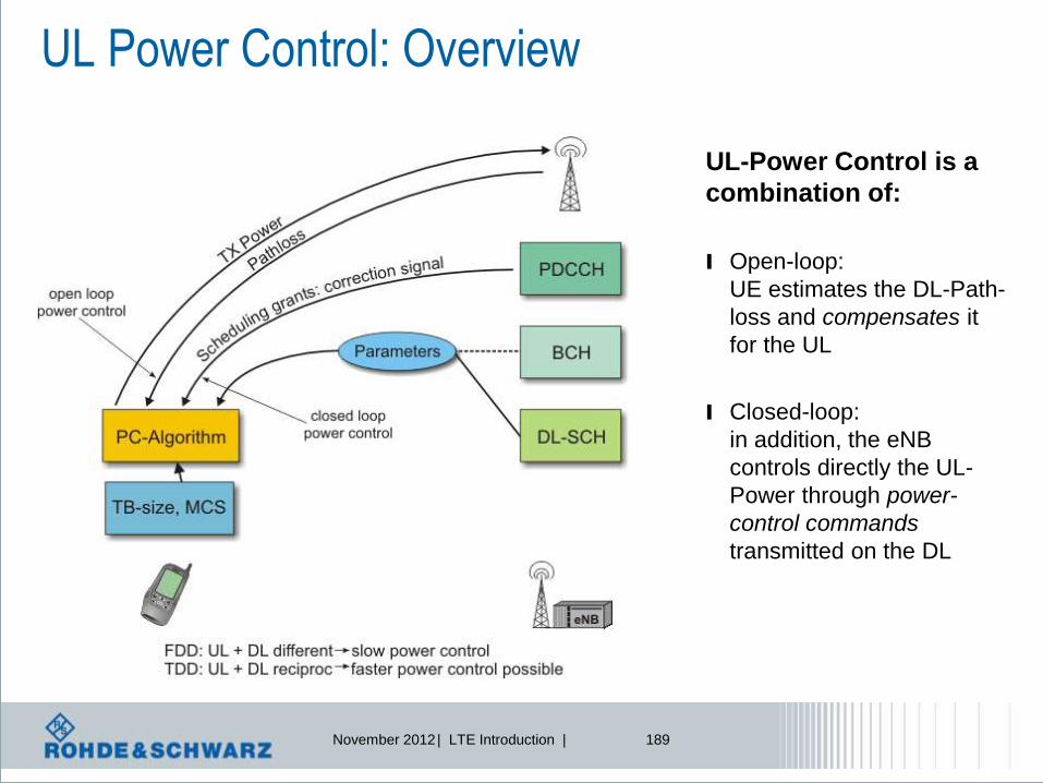
November 2012 | LTE Introduction | 189
UL Power Control: Overview
UL-Power Control is a
combination of:
l Open-loop:
UE estimates the DL-Path-
loss and compensates it
for the UL
l Closed-loop:
in addition, the eNB
controls directly the UL-
Power through power-
control commands
transmitted on the DL

November 2012 | LTE Introduction | 190
PUSCH power control
l Power level [dBm] of PUSCH is calculated every subframe i based on the following
formula out of TS 36.213
Dynamic offset (closed loop) Basic open-loop starting point
Maximum allowed UE power
in this particular cell,
but at maximum +23 dBm1)
Number of allocated
resource blocks (RB)
Combination of cell- and UE-specific
components configured by L3
Cell-specific
parameter
configured by L3
PUSCH transport
format
Transmit power for PUSCH
in subframe i in dBm
Power control
adjustment derived
from TPC command
received in subframe (i-4)
Downlink
path loss
estimate
Bandwidth factor
1) +23 dBm is maximum allowed power in LTE according to TS 36.101, corresponding to power class 3bis in WCDMA
MPR

November 2012 | LTE Introduction | 191
LTE RF Testing: UE Maximum Power
UE transmits
with 23dBm ±2 dB
QPSK modulation is used. All channel bandwidths are
tested separately. Max power is for all band classes
Test is performed for varios uplink allocations

November 2012 | LTE Introduction | 192
Resource Blocks number and maximum RF power
One active resource block
(RB) provides maximum
absolute RF power RF p
ow
er
Frequency
RF p
ow
er
Frequency
More RB’s in use will be at
lower RF power in order to
create same integrated
power
1 active resource block (RB),
Nominal band width 10 MHz = 50 RB’s
RF p
ow
er
Frequency
Additionally, MPR (Max.
Power Reduction) and A-
MPR are defined MPR

November 2012 | LTE Introduction | 193
UE maximum power
FUL_low FUL_high
PPowerClass + 2dB
PPowerClass - 2dB
maximum output
power for any
transmission bandwidth
within the channel bandwidth
23dBm
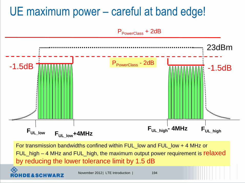
November 2012 | LTE Introduction | 194
UE maximum power – careful at band edge!
FUL_low FUL_high
PPowerClass + 2dB
PPowerClass - 2dB
23dBm
FUL_high- 4MHz FUL_low+4MHz
For transmission bandwidths confined within FUL_low and FUL_low + 4 MHz or
FUL_high – 4 MHz and FUL_high, the maximum output power requirement is relaxed
by reducing the lower tolerance limit by 1.5 dB
-1.5dB -1.5dB

November 2012 | LTE Introduction | 195
LTE RF Testing: UE Minimum Power
UE transmits
with -40dBm
All channel bandwidths are tested separately.
Minimum power is for all band classes < -39 dBm

November 2012 | LTE Introduction | 196
LTE RF Testing: UE Off Power
The transmit OFF power is defined as the mean power in a duration of at least one
sub-frame (1ms) excluding any transient periods. The transmit OFF power shall not
exceed the values specified in table below
Channel bandwidth / Minimum output power / measurement bandwidth
1.4
MHz
3.0
MHz
5
MHz
10
MHz
15
MHz
20
MHz
Transmit OFF power -50 dBm
Measurement
bandwidth 1.08 MHz 2.7 MHz 4.5 MHz 9.0 MHz 13.5 MHz 18 MHz

November 2012 | LTE Introduction | 197
Configured UE transmitted Output Power
Test: set P-Max to -10, 10 and 15 dBm, measure PCMAX
IE P-Max (SIB1) = PEMAX
Channel bandwidth / maximum output power
1.4
MHz
3.0
MHz
5
MHz
10
MHz
15
MHz
20
MHz
PCMAX test point 1 -10 dBm ± 7.7
PCMAX test point 2 10 dBm ± 6.7
PCMAX test point 3 15 dBm ± 5.7
To verify that UE follows rules sent via
system information, SIB

November 2012 | LTE Introduction | 198
LTE Power versus time
)}())(()())((log10,min{)( TFO_PUSCHPUSCH10MAXPUSCH ifiTFPLjPiMPiP
Bandwidth allocation TPC commands Given by higher layers
or not used
RB allocation
is main source for
power change
Not scheduled
Resource block

November 2012 | LTE Introduction | 199
2
Accumulative TPC commands
TPC Command Field
In DCI format 0/3
Accumulated
[dB]
0 -1
1 0
2 1
3 3
PUSCH
minimum
power in LTE

November 2012 | LTE Introduction | 200
Absolute TPC commands
TPC Command Field
In DCI format 0/3
Absolute [dB]
only DCI format 0
0 -4
1 -1
2 1
3 4
PUSCH
Pm
)}())(()())((log10,min{)( TFO_PUSCHPUSCH10MAXPUSCH ifiTFPLjPiMPiP
-4 -1

November 2012 | LTE Introduction | 201
Relative Power Control
0 .. 9 sub-frame# 1 2 3 4 radio frame
0 .. 9 sub-frame# 1 2 3 4 radio frame
RB change
RB change
Power pattern A
Power pattern C
0 .. 9 sub-frame# 1 2 3 4 radio frame
RB change
Power pattern B
l The purpose of this test is to verify
the ability of the UE transmitter to set
its output power relatively to the
power in a target sub-frame, relatively
to the power of the most recently
transmitted reference sub-frame, if the
transmission gap between these sub-
frames is ≤ 20 ms.

November 2012 | LTE Introduction | 202
Power Control – Relative Power Tolerance
l Various power ramping patterns are defined
ramping up
ramping down
alternating

November 2012 | LTE Introduction | 203
UE power measurements – relative power change
Power
FDD test patterns
0 1 9 sub-frame#
Power
TDD test patterns
0 2 3 7 8 9 sub-frame#
Sub-test Uplink RB allocation TPC command Expected power
step size
(Up or
down)
Power step size
range (Up or
down)
PUSCH/
ΔP [dB] ΔP [dB] [dB]
A Fixed = 25 Alternating TPC =
+/-1dB 1 ΔP < 2 1 ± (1.7)
B Alternating 10 and 18 TPC=0dB 2.55 2 ≤ ΔP < 3 2.55 ± (3.7)
C Alternating 10 and 24 TPC=0dB 3.80 3 ≤ ΔP < 4 3.80 ± (42.)
D Alternating 2 and 8 TPC=0dB 6.02 4 ≤ ΔP < 10 6.02 ± (4.7)
E Alternating 1 and 25 TPC=0dB 13.98 10 ≤ ΔP < 15 13.98 ± (5.7)
F Alternating 1 and 50 TPC=0dB 16.99 15 ≤ ΔP 16.99 ± (6.7)
test for
each
bandwidth,
here 10MHz

November 2012 | LTE Introduction | 204
UE aggregate power tolerance
Aggregate power control tolerance is the ability of a UE to maintain its power in
non-contiguous transmission within 21 ms in response to 0 dB TPC commands
TPC command UL channel Aggregate power tolerance within 21 ms
0 dB PUCCH ±2.5 dB
0 dB PUSCH ±3.5 dB
Note:
1. The UE transmission gap is 4 ms. TPC command is transmitted via PDCCH 4 subframes preceding
each PUCCH/PUSCH transmission.
P
Time = 21 milliseconds
UE power with
TPC = 0
Tolerated UE power
deviation

November 2012 | LTE Introduction | 205
UE aggregate power tolerance
Power
FDD test patterns
0 5 0 5 0
sub-frame#
Power
TDD test patterns
3 8 3 8 3
sub-frame#
Test performed with scheduling gap of 4 subframes
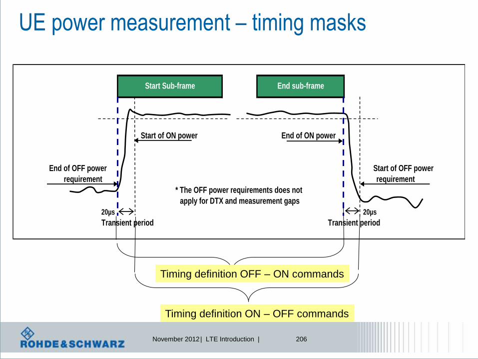
November 2012 | LTE Introduction | 206
UE power measurement – timing masks
End of OFF power
20µs 20µs
Transient period Transient period
Start of OFF power
Start of ON power
requirement
Start Sub-frame End sub-frame
End of ON power
requirement
* The OFF power requirements does not
apply for DTX and measurement gaps
Timing definition OFF – ON commands
Timing definition ON – OFF commands

November 2012 | LTE Introduction | 207
Power dynamics
PUSCH = ON PUSCH = OFF PUSCH = OFF time
Please note: scheduling cadence for power dynamics

November 2012 | LTE Introduction | 208
Tx power aspects RB power = Ressource Block Power, power of 1 RB TX power = integrated power of all assigned RBs

November 2012 | LTE Introduction | 209
Resource allocation versus time
PUSCH allocation, different #RB and RB offset
PUCCH
allocation
No resource
scheduled
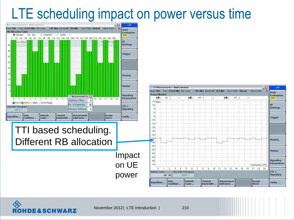
November 2012 | LTE Introduction | 210
LTE scheduling impact on power versus time
TTI based scheduling.
Different RB allocation
Impact
on UE
power

November 2012 | LTE Introduction | 211
Transmit signal quality – carrier leakage
f
Parameters Relative Limit (dBc)
Output power >0 dBm -25
-30 dBm ≤ Output power ≤0 dBm -20
-40 dBm Output power < -30 dBm -10
Carrier leakage (The IQ origin offset) is an additive sinusoid waveform
that has the same frequency as the modulated waveform carrier frequency.
Frequency error
fc Fc+ε

November 2012 | LTE Introduction | 212
Impact on Tx modulation accuracy evaluation
l 3 modulation accuracy requirements
l EVM for the allocated RBs
l LO leakage for the centred RBs ! LO spread on all RBs
l I/Q imbalance in the image RBs
frequency
RF carrier
RB0 RB1 RB2 RB3 RB4 RB5
level
signal
noise
LO leakage
I/Q imbalance
EVM

November 2012 | LTE Introduction | 213
Inband emissions
Used
allocation <
½ channel
bandwidth
channel bandwidth
3 types of inband emissions: general, DC and IQ image

November 2012 | LTE Introduction | 214
Carrier Leakage Carrier leakage (the I/Q origin offset) is a form of interference caused by crosstalk or DC offset.
It expresses itself as an un-modulated sine wave with the carrier frequency.
I/Q origin offset interferes with the center sub carriers of the UE under test.
The purpose of this test is to evaluate the UE transmitter to verify its modulation quality in
terms of carrier leakage.
DC carrier leakage
due to IQ offset
LO
Leakage
Parameters Relative
Limit (dBc)
Output power >0 dBm -25
-30 dBm ≤ Output power ≤0 dBm -20
-40 dBm Output power < -30 dBm -10
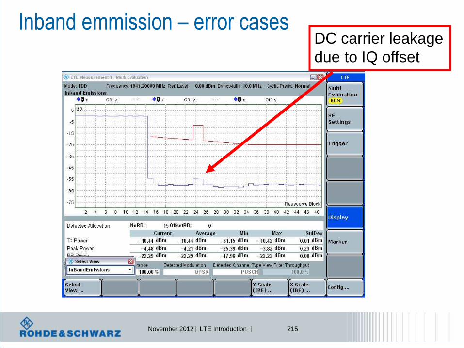
November 2012 | LTE Introduction | 215
Inband emmission – error cases DC carrier leakage
due to IQ offset

November 2012 | LTE Introduction | 216
Inband emmission – error cases Inband image
due to IQ inbalance
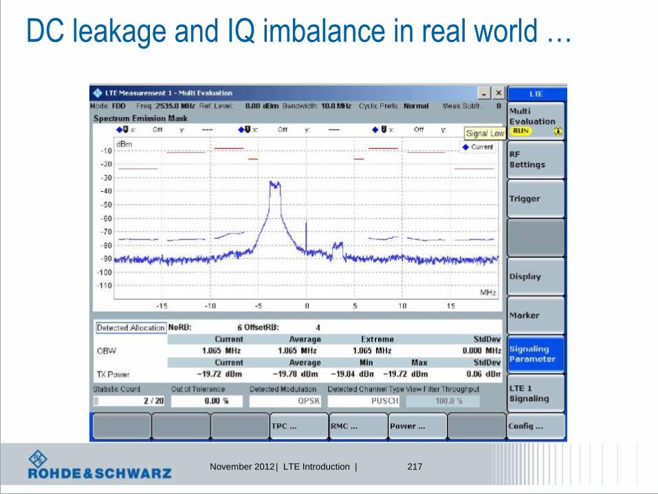
November 2012 | LTE Introduction | 217
DC leakage and IQ imbalance in real world …
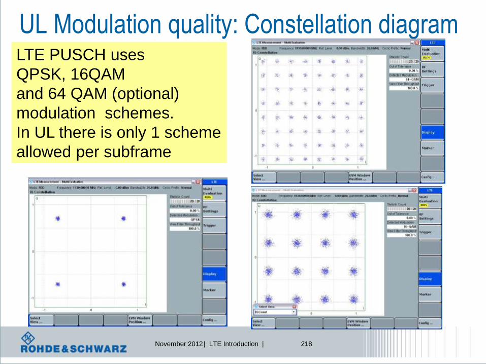
November 2012 | LTE Introduction | 218
UL Modulation quality: Constellation diagram LTE PUSCH uses
QPSK, 16QAM
and 64 QAM (optional)
modulation schemes.
In UL there is only 1 scheme
allowed per subframe

November 2012 | LTE Introduction | 219
Error Vector Magnitude, EVM
Error Vector
Q
I
Ideal (Reference) Signal
Measured
Signal
Φ
Phase Error (IQ error phase)
Magnitude Error (IQ error magnitude)
Σ
Demodulator Ideal
Modulator Input Signal
-
+
011001…
Reference Waveform
Measured Waveform
Difference Signal
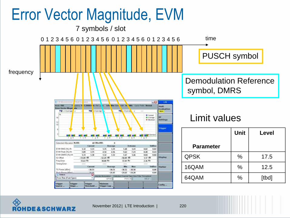
November 2012 | LTE Introduction | 220
Error Vector Magnitude, EVM 7 symbols / slot
0 1 2 3 4 5 6 0 1 2 3 4 5 6 0 1 2 3 4 5 6 0 1 2 3 4 5 6 time
frequency
PUSCH symbol
Demodulation Reference
symbol, DMRS
Parameter
Unit Level
QPSK % 17.5
16QAM % 12.5
64QAM % [tbd]
Limit values

November 2012 | LTE Introduction | 221
Error Vector Magnitude, EVM
Cyclic
prefix
OFDM
Symbol
Part equal
to CP
1 SC-FDMA symbol, including Cyclic Prefix, CP CP center
FFT Window size
FFT window size depends
on channel bandwidth and
extended/normal CP length

November 2012 | LTE Introduction | 222
Cyclic prefix aspects
OFDM symbol is periodic!
Cyclic prefix does not provoque
phase shift
OFDM symbol n OFDM symbol n-1
We can observe a phase shift
Content is
different in each
OFDM symbol
CP CP
part CP
CP
part
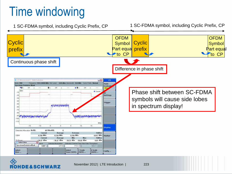
November 2012 | LTE Introduction | 223
Time windowing
Cyclic
prefix
OFDM
Symbol
Part equal
to CP
1 SC-FDMA symbol, including Cyclic Prefix, CP
Cyclic
prefix
OFDM
Symbol
Part equal
to CP
1 SC-FDMA symbol, including Cyclic Prefix, CP
Continuous phase shift
Difference in phase shift
Phase shift between SC-FDMA
symbols will cause side lobes
in spectrum display!

November 2012 | LTE Introduction | 224
Time windowing
Cyclic
prefix
OFDM
Symbol
Part equal
to CP
Cyclic
prefix
OFDM
Symbol
Part equal
to CP
Continuous phase shift Difference in phase shift
Tx Time window Tx Time window
Tx time window creates
some kind of clipping in
symbol transitions
Tx time window can be used
to shape the Tx spectrum in
a more steep way, but ….

November 2012 | LTE Introduction | 225
Time windowing
Cyclic
prefix
OFDM
Symbol
Part equal
to CP
Cyclic
prefix
OFDM
Symbol
Part equal
to CP
Continuous phase shift Difference in phase shift
Tx Time window Tx Time window
Tx time window creates
some kind of clipping in
symbol transitions
Tx time window will create
a higher Error Vector Magnitude!
Here the Tx time window of 5µsec causes
Some mismatch between the 2 EVM
Measurements of the first SC-FDMA symbol

November 2012 | LTE Introduction | 226
EVM vs. subcarrier
f
f0 f2 f1 f3
Nominal subcarriers
Each subcarrier
Modulated with
e.g. QPSK
. . . .
Integration of all
Error Vectors to
Display EVM curve
Error vector
Error vector
Note: simplified figure: in reality you
compare the waveforms due to SC-FDMA

November 2012 | LTE Introduction | 227
EVM vs. subcarrier

November 2012 | LTE Introduction | 228
EVM Equalizer Spectrum Flatness
2
2
*12
|)((|
|))((|*12
1
log*10)(fECA
fECAN
fP RBNRB
f
f0 f2 f1 f3
Nominal subcarriers
Subcarriers before
equalization
Amplitude Equalizer
coefficients
Integration of all
amplitude equalizer
coefficients to display
spectral flatness curve
The EVM equalizer spectrum flatness is defined as the variation in dB of the equalizer coefficients
generated by the EVM measurement process.
The EVM equalizer spectrum flatness requirement does not limit the correction applied to the signal
in the EVM measurement process but for the EVM result to be valid,
the equalizer correction that was applied must meet the
EVM equalizer spectral flatness minimum requirements.

November 2012 | LTE Introduction | 229
Spectrum flatness calculation
A(f)
f
Equalizer tries to
set same power level for
all subcarriers
1-tap equalization =
Interpreting the frequency
Selectivity as scalar factor
1-tap equalization =
Calculating scalar to
amplify or attenuate 2
2
*12
|)((|
|))((|*12
1
log*10)(fECA
fECAN
fP RBNRB
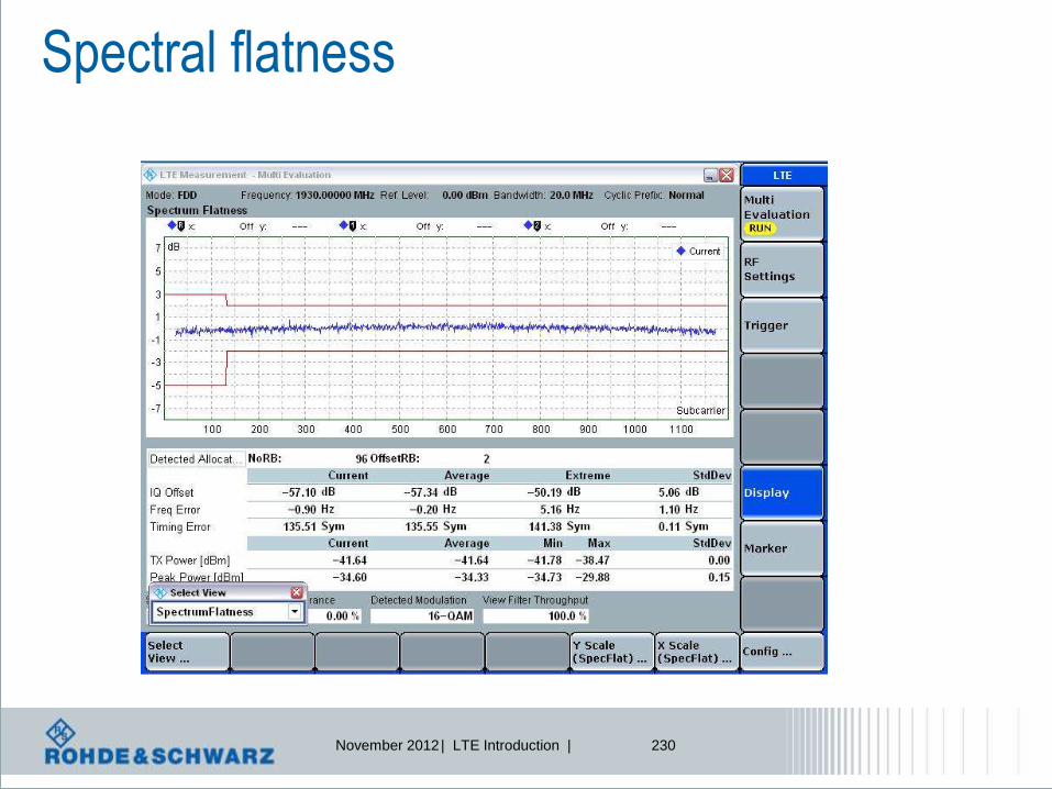
November 2012 | LTE Introduction | 230
Spectral flatness

November 2012 | LTE Introduction | 231
Harmonics, parasitic
emissions, intermodulation
and frequency conversion
from
modulation
process
Output RF Spectrum Emissions
Spurious domain
RB
Channel bandwidth Spurious domain
ΔfOOB
ΔfOOB
E-UTRA Band
Worst case:
Resource Blocks allocated at
channel edge
Spectrum Emission Mask – SEM
-> measurement point by point (RBW)
Adjacent Channel Leakage Ratio – ACLR
-> integration (channel bandwidth)
occupied
bandwidth
Out-of-band emissions Spurious Emissions

November 2012 | LTE Introduction | 232
Adjacent Channel Leakage Ratio, ACLR
2 adjacent WCDMA
carriers, 5MHz BW
1 adjacent LTE
carrier, 20MHz BW
Active LTE
carrier, 20MHz BW
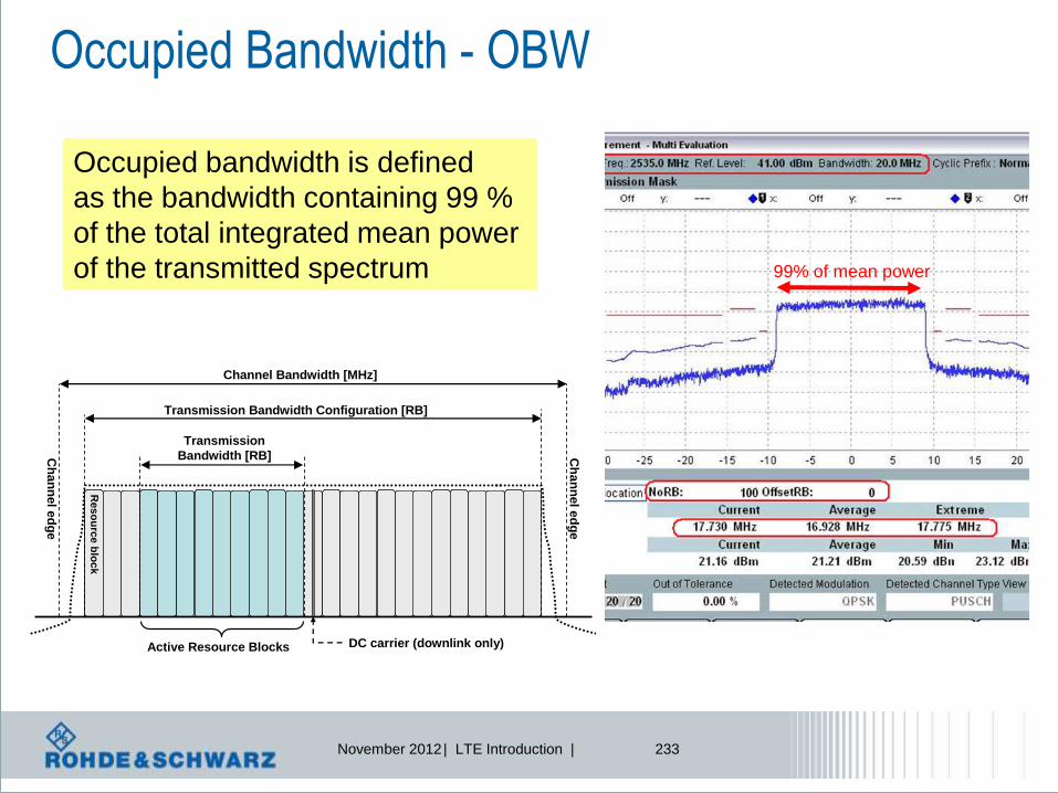
November 2012 | LTE Introduction | 233
Occupied Bandwidth - OBW
99% of mean power
Occupied bandwidth is defined
as the bandwidth containing 99 %
of the total integrated mean power
of the transmitted spectrum
Transmission
Bandwidth [RB]
Transmission Bandwidth Configuration [RB]
Channel Bandwidth [MHz]
Res
ou
rce
blo
ck
Ch
an
nel e
dg
e
Ch
an
nel e
dg
e
DC carrier (downlink only)Active Resource Blocks

November 2012 | LTE Introduction | 234
Impact on SEM limit definition
Spectrum emission limit (dBm)/ Channel bandwidth
ΔfOOB
(MHz)
1.4
MH
z
3.0
M
Hz
5
M
Hz
10
M
Hz
15
M
Hz
20
M
Hz
Measurement
bandwidth
0-1 -10 -13 -15 -18 -20 -21 30 kHz
1-2.5 -10 -10 -10 -10 -10 -10 1 MHz
2.5-5 -25 -10 -10 -10 -10 -10 1 MHz
5-6 -25 -13 -13 -13 -13 1 MHz
6-10 -25 -13 -13 -13 1 MHz
10-15 -25 -13 -13 1 MHz
15-20 -25 -13 1 MHz
20-25 -25 1 MHz
Limits depend
on channel
bandwidth
Limits vary
dependent on offset
from assigned BW

November 2012 | LTE Introduction | 235
LTE Uplink: PUCCH
frequency
Allocation of
PUCCH only.

November 2012 | LTE Introduction | 236
PUCCH measurements
PUCCH is transmitted on the 2 side
parts of the channel bandwidth

November 2012 | LTE Introduction | 237
LTE Receiver Measurements
1 Reference sensitivity level
2 Maximum input level
3 Adjacent Channel Selectivity (ACS)
4 Blocking characteristics
4.1 In-band blocking
4.2 Out-of-band blocking
4.3 Narrow band blocking
5 Spurious response
6 Intermodulation characteristics
6.1 Wide band Intermodulation
7 Spurious emissions
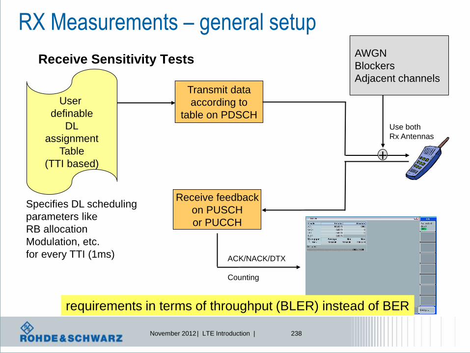
November 2012 | LTE Introduction | 238
RX Measurements – general setup
Receive Sensitivity Tests
User
definable
DL
assignment
Table
(TTI based)
Specifies DL scheduling
parameters like
RB allocation
Modulation, etc.
for every TTI (1ms)
Transmit data
according to
table on PDSCH
ACK/NACK/DTX
Counting
Receive feedback
on PUSCH
or PUCCH
+
AWGN
Blockers
Adjacent channels
requirements in terms of throughput (BLER) instead of BER
Use both
Rx Antennas

November 2012 | LTE Introduction | 239
RX sensitivity level
Channel bandwidth
E-UTRA
Ban
d
1.4 MHz
(dBm)
3 MHz
(dBm)
5 MHz
(dBm)
10 MHz
(dBm)
15 MHz
(dBm)
20 MHz
(dBm)
Duplex
Mode
1 - - -100 -97 -95.2 -94 FDD
2 -104.2 -100.2 -98 -95 -93.2 -92 FDD
3 -103.2 -99.2 -97 -94 -92.2 -91 FDD
4 -106.2 -102.2 -100 -97 -95.2 -94 FDD
5 -104.2 -100.2 -98 -95 FDD
6 - - -100 -97 FDD
Criterion: throughput shall be > 95% of possible maximum
(depend on RMC)
Sensitivity depends on band,
channel bandwidth and RMC
under test
Extract from TS 36.521
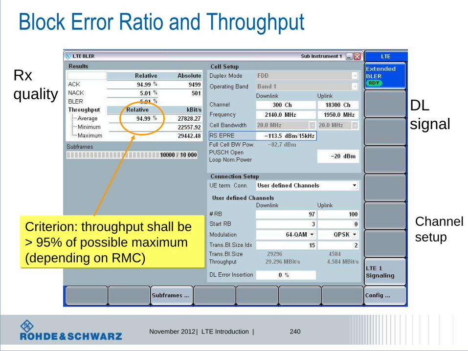
November 2012 | LTE Introduction | 240
Block Error Ratio and Throughput
Rx
quality DL
signal
Channel
setup Criterion: throughput shall be
> 95% of possible maximum
(depending on RMC)
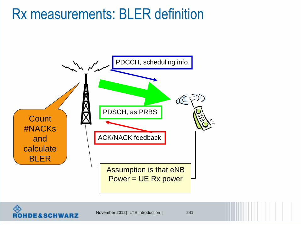
November 2012 | LTE Introduction | 241
Rx measurements: BLER definition
PDCCH, scheduling info
PDSCH, as PRBS
ACK/NACK feedback
Count
#NACKs
and
calculate
BLER
Assumption is that eNB
Power = UE Rx power

November 2012 | LTE Introduction | 242
Details LTE FDD signaling Rx Measurements
l Rx Measurements
l Counting
– ACKnowledgement (ACK)
– NonACKnowledgement
(NACK)
– DTX (no answer from UE)
l Calculating
l BLER (NACK/ALL)
l Throughput [kbps]

November 2012 | LTE Introduction | 243
Rx measurements: BLER definition
PDCCH, scheduling info
PDSCH, user data
ACK/NACK feedback
•ACK = UE properly
Receives PDCCH + PDSCH
•NACK = UE properly receives
PDCCH but does not understand
PDSCH
•DTX = UE does not understand
PDCCH
ACK relative =
NACK relative =
DTX relativ =
DTXNACKACK
ACK
###
#
DTXNACKACK
NACK
###
#
DTXNACKACK
DTX
###
#
BLER = DTXNACKACK
DTXNACK
###
##

November 2012 | LTE Introduction | 244
Throughput versus SNR

November 2012 | LTE Introduction | 245
Throughput measurements
Max throughput
possible in SISO

November 2012 | LTE Introduction | 246
Rx measurements - throughput
Throughput
Measurement,
Settings for max
throughput
for SISO:
Number of
Resource blocks
Modulation scheme
Transport block size

November 2012 | LTE Introduction | 247
Throughput + CQI in LTE
Change of
RF
condition-
> lower
data rate
UE sends
different
CQI
values

November 2012 | LTE Introduction | 248
MIMO in LTE: BLER and throughput

November 2012 | LTE Introduction | 249
Throughput measurements
MIMO active,
2 streams with
different data rate

November 2012 | LTE Introduction | 250
Why do we need fading?
l 3GPP specifies various tests under conditions of fading
l WCDMA performance tests
l HSDPA performance tests
l LTE performance tests
l LTE reporting of channel state information tests
See CMW capability lists for details
l Evaluation of MIMO performance gain requires fading
l Correlated transmission paths in MIMO connection
l Simulation of “real life conditions” in the lab
l Comparison of processing gain for different transmission modes

November 2012 | LTE Introduction | 251
Most popular MIMO scheme to increase data rates: Spatial Multiplexing
TX
Ant 1
TX
Ant 2
Time
RX
Ant 1
h11
h21
n1
r1
MIMO
RX(e.g. ZF,
MMSE,MLD)
de2
de1
Sp
ace
d1
d2
Matix B
LO
n2
r2
h12
h22
RX
Ant 2
2 X 2
MIMO
Doubles max. data rates, however, at the expense of SNR @ receiver.
Thus, according to Shannon‘s law, decrease of performance.
Makes sense for low order modulation schemes only (QPSK, 16QAM),
or in case of very good SNR conditions, e.g. for receivers close to base stations.
No increase of total transmit power, i.e. distribution of transmit power across multiple transmit antennas!
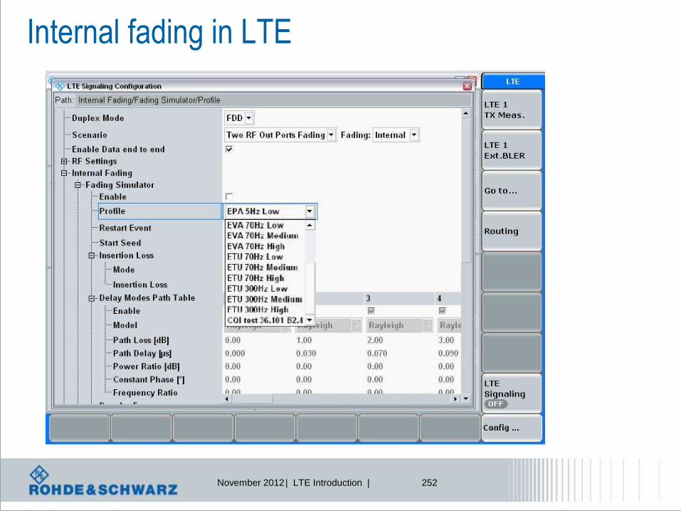
November 2012 | LTE Introduction | 252
Internal fading in LTE
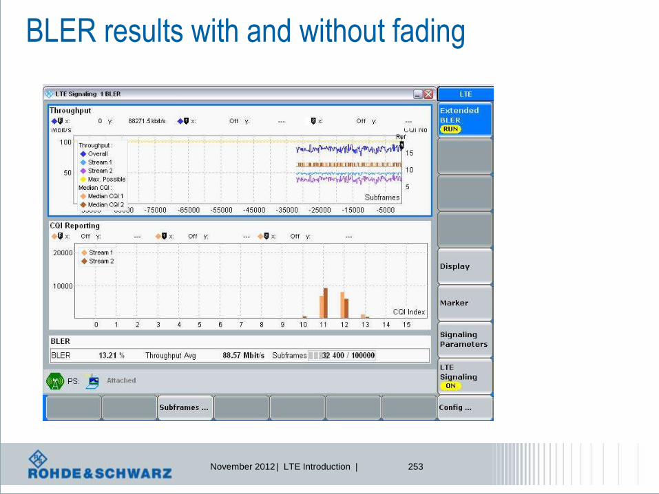
November 2012 | LTE Introduction | 253
BLER results with and without fading
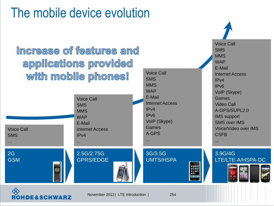
November 2012 | LTE Introduction | 254
The mobile device evolution
2G
GSM
Voice Call
SMS
…
2.5G/2.75G
GPRS/EDGE
Voice Call
SMS
MMS
WAP
Internet Access
IPv4
...
3G/3.5G
UMTS/HSPA
Voice Call
SMS
MMS
WAP
Internet Access
IPv4
IPv6
VoIP (Skype)
Games
A-GPS
...
3.9G/4G
LTE/LTE-A/HSPA-DC
Voice Call
SMS
MMS
WAP
Internet Access
IPv4
IPv6
VoIP (Skype)
Games
Video Call
A-GPS/SUPL2.0
IMS support
SMS over IMS
Voice/Video over IMS
CSFB
...

November 2012 | LTE Introduction | 255
Why End-to-End testing?
Smartphone
Voice Call
SMS
MMS
WAP
Internet Access
IPv4
IPv6
VoIP (Skype)
Games
Video Call
A-GPS/SUPL2.0
IMS support
SMS over IMS
Voice/Video over IMS
CSFB
...
All features on a phone have an direct impact on the battery life of the phone and it’s
power consumption, but also on the generated traffic by the phone.
Keywords: lHW and SW of a phone need to be designed in an efficient way for a long battery life
lHW and SW need to be designed in a way, that they provide the service reliable
lEfficient application desig for low IP traffic
...
Focus: lValidation of HW and SW in combination
l Simulation of end-user scenarios in an isolated and controlled environment
l Validation of applications with repeatable and comparable results
…
That‘s why End-to-End test!

November 2012 | LTE Introduction | 256
Here it is!
Embedded PC
based on Linux!
The „Data Application Unit“!

November 2012 | LTE Introduction | 257
CMW DAU - Main Features
1. Easy Data Testing IP configuration
l Ready to use Standalone IP configuration for the CMW
l Easy Company LAN integration (DHCPv4, static IP addresses)
l Data continuity during Handover between RATs
l Remote control by MLAPI & SCPI
2. DAU IP services (Applications)
l Provides R&S throughput optimized data applications (ftp, http, …)
l New features like IMS (for VoLTE or SMS over IMS)
l Provides storage for media files (own Hard Disk)
3. Closed environment
l guaranties repeatable and comparable test results

November 2012 | LTE Introduction | 258
DAU User Interface on the CMW
l Data Application Control (DAC)
l Accessible via Setup-> System -> DAU -> Go to Config
l Data Testing IP configuration
l Start/Stop, Configure global servers like FTP, HTTP

November 2012 | LTE Introduction | 259
DAU User Interface on the CMW
l Data Application Measurements (DAM)
l Accessible over the CMW Measurements
l Provides User Interface for
– Applications: start Iperf, trigger Ping, send/receive eMails …
– Measurements: Throughput, Traffic statistics
Go to
DAC

November 2012 | LTE Introduction | 260
Feature Set FW2.1.26
Latency
measurements Overall Throughput
Indication
IPERF Throughput
Measurement

November 2012 | LTE Introduction | 261
Throughput end to end

November 2012 | LTE Introduction | 262
End to end testing – ping response, RTT
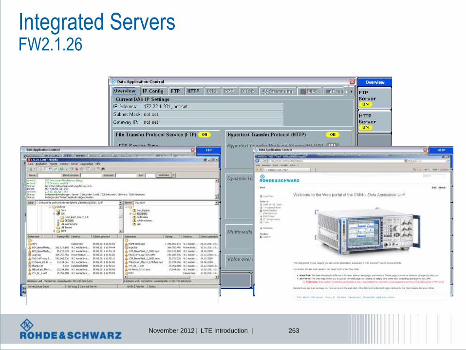
November 2012 | LTE Introduction | 263
Integrated Servers FW2.1.26

November 2012 | LTE Introduction | 264
Introduction IMS – IP Multimedia Subsystem Definition
l IMS (IP multimedia subsystem) itself is not a technology,
it is an architecture
l IMS is an all-IP service layer between transport and application
layer based on common Internet protocols
l IMS architecture enables the connection to networks using
multiple mobile and fixed devices and technologies
l IMS defines an architecture for the convergence of audio, video
and data to enable integrated Multimedia Sessions over fixed and
wireless networks
l The long-term solution for supporting voice services in LTE will be
based on the IMS (IP Multimedia Subsystem) framework.

November 2012 | LTE Introduction | 265
Introduction IMS – IP Multimedia Subsystem Definition
l TBD
Services: SMS over IMS
Voice over IMS
Video over IMS
IMS is a global access-independent and standard-based IP connectivity
and service control architecture that enables various types of
multimedia services to end-users using common Internet-based
protocols.

November 2012 | LTE Introduction | 266
3 GPP System Architecture Evolution
S-GW P-GW
Evolved nodeB UE
external
Evolved Packet Core
RAN
IMS
PSTN
PDN MME
Signaling interfaces
Data transport interfaces
All interfaces are packet switched
Access PDN
directly or via IMS
IMS to control
access + data
transfer

November 2012 | LTE Introduction | 267
IMS Architecture

November 2012 | LTE Introduction | 269
IMS protocol structure
Layer 1/2 Layer 1/2 (other IP CAN)
Layer 3 control IP / IP sec
UDP / TCP / SCTP
SIP/SDP IKE RTP MSRP
Voice
video messaging
Control plane
user plane
Mobile com specific protocols IMS specific protocols
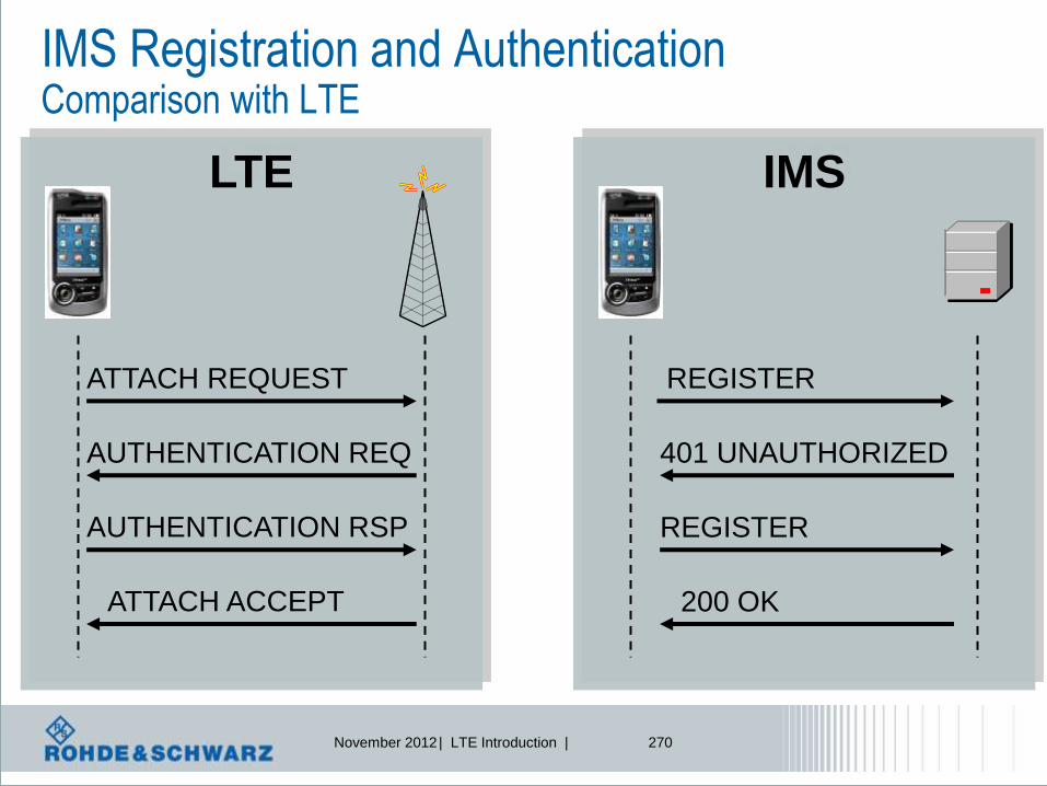
November 2012 | LTE Introduction | 270
IMS LTE
IMS Registration and Authentication Comparison with LTE
ATTACH REQUEST REGISTER
AUTHENTICATION REQ
AUTHENTICATION RSP
ATTACH ACCEPT
401 UNAUTHORIZED
REGISTER
200 OK
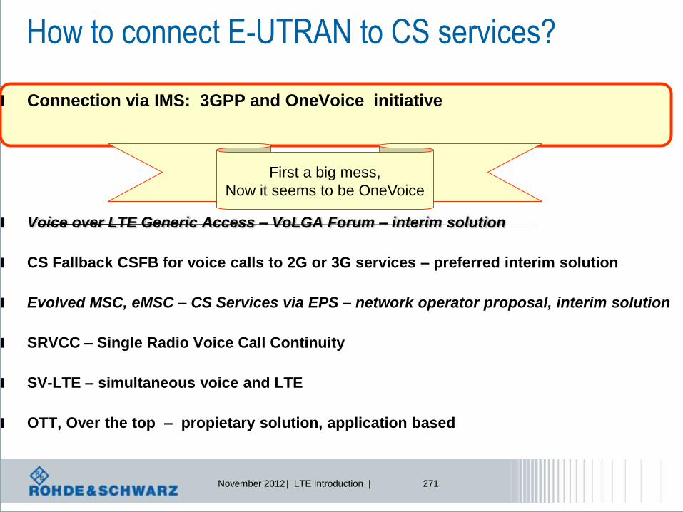
November 2012 | LTE Introduction | 271
How to connect E-UTRAN to CS services?
l Connection via IMS: 3GPP and OneVoice initiative
l Voice over LTE Generic Access – VoLGA Forum – interim solution
l CS Fallback CSFB for voice calls to 2G or 3G services – preferred interim solution
l Evolved MSC, eMSC – CS Services via EPS – network operator proposal, interim solution
l SRVCC – Single Radio Voice Call Continuity
l SV-LTE – simultaneous voice and LTE
l OTT, Over the top – propietary solution, application based
First a big mess,
Now it seems to be OneVoice

November 2012 | LTE Introduction | 272
Voice over IMS: IMS protocol profile Codec mode Source codec bit-rate
AMR_12.20 12,20 kbit/s (GSM EFR)
AMR_10.20 10,20 kbit/s
AMR_7.95 7,95 kbit/s
AMR_7.40 7,40 kbit/s (IS-641)
AMR_6.70 6,70 kbit/s (PDC-EFR)
AMR_5.90 5,90 kbit/s
AMR_5.15 5,15 kbit/s
AMR_4.75 4,75 kbit/s
AMR_SID 1,80 kbit/s (see note 1)
Adaptive Multirate
Codecs are used
In VoIP over IMS
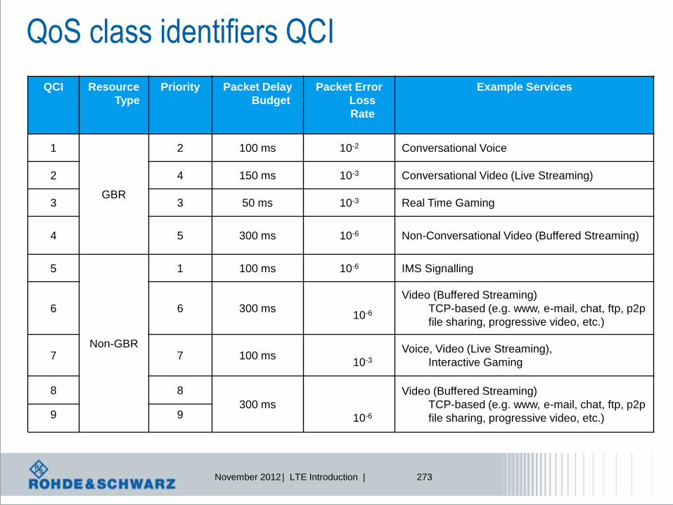
November 2012 | LTE Introduction | 273
QoS class identifiers QCI
QCI Resource
Type
Priority Packet Delay
Budget
Packet Error
Loss
Rate
Example Services
1
GBR
2 100 ms 10-2 Conversational Voice
2 4 150 ms 10-3 Conversational Video (Live Streaming)
3 3 50 ms 10-3 Real Time Gaming
4 5 300 ms 10-6 Non-Conversational Video (Buffered Streaming)
5
Non-GBR
1 100 ms 10-6 IMS Signalling
6 6 300 ms
10-6
Video (Buffered Streaming)
TCP-based (e.g. www, e-mail, chat, ftp, p2p
file sharing, progressive video, etc.)
7 7 100 ms
10-3
Voice, Video (Live Streaming),
Interactive Gaming
8 8
300 ms
10-6
Video (Buffered Streaming)
TCP-based (e.g. www, e-mail, chat, ftp, p2p
file sharing, progressive video, etc.) 9 9

November 2012 | LTE Introduction | 274
Voice over LTE – protocol profiles
PHYSICAL LAYER
Medium Access Control
MAC
Radio Link Control
RLC
Packet Data Convergence
PDCP
UDP/ TCP
IP
AMR codec
Use robust header compression or IP
Short PDCP header is used
Use RLC in UM mode
Small sequence number is used
SRB1 and 2 are supported for
DCCH + one UM DRB with QCI 1 for voice
for SIP signaling + one AM DRB QCI 5 for
SIP signaling + one AM DRB QCI 8 for
IMS traffic
TTI bundling + DRX to reduce PDCCH
Signaling + Semi-persistend scheduling
Optimize transmission of
Voice by configuring
Lower layers

November 2012 | LTE Introduction | 275
CMW500 Data Application Unit Integrated IMS Server
IMS infoscreen
Mobile infoscreen
IMS
Configuration
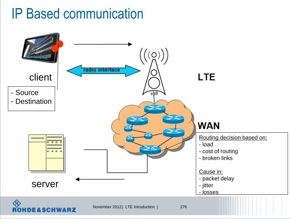
November 2012 | LTE Introduction | 276
IP Based communication
server
client
- Source
- Destination
Routing decision based on:
- load
- cost of routing
- broken links
Cause in:
- packet delay
- jitter
- losses

November 2012 | LTE Introduction | 277
CMW500 Data Application Unit Network Impairment
DAU
l Impairments:
l Delay
l Jitter
l Packet Loss
l Packet Corruption
l Packet Duplication
l Packet Re-ordering
TUN
LAN
DA
U
NOTE: Network Impairment are available for DL traffic
Delay Loss
Application FTP PING HTTP IPERF
Emulate characteristics of a real network

November 2012 | LTE Introduction | 278
l UP to 7 different Impairment per DAM possible
l Impairments are identified by a filter rule
l IPv4 address filter
l IPv6 address/prefix filter
l Additionally a optional TCP/UDP Port filter
l Feedback provided when error occur
CMW500 Data Application Unit Network Impairment

November 2012 | LTE Introduction | 279
Functional
testing
Performance
testing
Audio
Quality
testing
Voice over LTE (VoLTE) testing R&S solutions - Overview
LTE attach procedure
IMS Terminal Testing
Session Initiation Protocol (SIP)
Conformance Testing
Audio: echo verification in
loopback mode
Verify audio quality using PESQ®
and POLQA® algorithm
Acoustic analysis: 3GPP TS 26.132
R&S®CMW500
LTE Call-box
R&S®UPV
Audio Analyzer
R&S®CMW500 LTE Protocol Tester
Automated test of impacts of noise, fading, IP traffic impairment…
with R&S Contest
LTE attach procedure
IMS registration
Audio: echo verification in
loopback mode
IP Traffic Logging
Impact of noise, IP traffic impairment
R&S®CMW-PQA

November 2012 | LTE Introduction | 280
LTE CallBox used for VoLTE Audio Quality Testing
R&S®CMW500
LTE Call-box
R&S®UPV
Audio Analyzer
Scope of Audio Quality testing
lAnalysis of the Audio Quality
l„What is the Audio Quality of the VoLTE call a UE
can perform?“
lVerification of the audio quality with established
mechanisms like PESQ® and POLQA® algorithm
lAcoustic analysis of the signal according to 3GPP
TS 26.132 Release 10
Audio
Quality
testing
Performance
testing
Functional
testing
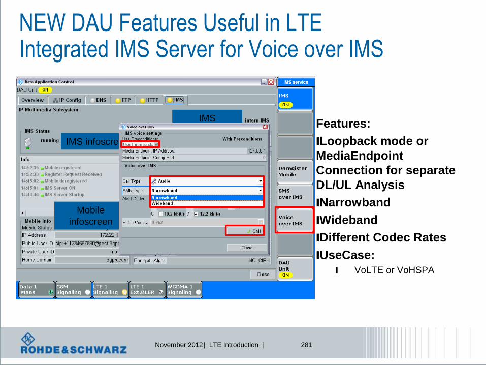
November 2012 | LTE Introduction | 281
NEW DAU Features Useful in LTE Integrated IMS Server for Voice over IMS
IMS infoscreen
Mobile
infoscreen
IMS
Configuration
Features:
lLoopback mode or
MediaEndpoint
Connection for separate
DL/UL Analysis
lNarrowband
lWideband
lDifferent Codec Rates
lUseCase: l VoLTE or VoHSPA

November 2012 | LTE Introduction | 282
l CMW500 establishes LTE
and IMS connection to UE
l Uplink verification:
PESQ/POLQA sequence
from UPV is provided to
UE and sent in uplink to
CMW500; received VoIP
data is converted to analog
(USB soundcard) and
analyzed in UPV
l Test focus:
l UPV analyzes the audio
quality PESQ/POLQA
l Verification of separated
uplink
PESQ/POLQA
analysis
IMS
server Media
Server* RF
to m
icro
ph
one
USB
Connection
*Media Server functionality:
l De-packaging speech data from RTP
l De-Coding digital speech data (e.g. AMR WB)
CMW500 Speech Verification Audio Quality analysis - Uplink

November 2012 | LTE Introduction | 283
CMW500 Speech Verification Acoustic tests according to 3GPP TS 26.132
l CMW500 establishes LTE
and IMS connection to UE
l DL or UL verification:
3GGP defined tests
performed by UPV using
an artificial head
l Test focus:
l Acoustic tests according to
3GPP TS 26.132
l Verification of uplink and
downlink
3GPP
TS26.132
analysis
IMS
server
LAN Connection
RF
to m
icro
ph
one
USB
Connection
*Media Server functionality:
l De-packaging speech data from RTP
l De-Coding digital speech data (e.g. AMR WB) fr
om
lo
ud
sp
eaker
Media
Server*

November 2012 | LTE Introduction | 284
Final Test Setup for VoLTE Acoustic measurements Integrated IMS, integrated Audio Board and Codecs
l CMW500 establishes LTE
and IMS connection to UE
l establish a VoLTE call
by using internal audio
board and codecs
l Test focus:
l Audio Quality Analysis
PESQ/POLQA
l Acoustic tests according to
3GPP TS 26.132 with artificial
head
PESQ/POLQA
analysis
IMS
server Audio
Codecs
RF
to m
icro
ph
one
UL
Fro
m lou
dsp
ea
ker
DL
Integrated
Audioboard

November 2012 | LTE Introduction | 285
l Support of different RATs
l Server for FTP, HTTP, IMS and DNS
l IP Impairments
l IP Logging
l IMS Services SMS and VoIP
l PING Latency
l IPERF DNS IPERF TP Streaming
Feature overview with 3.0.20
LTE-FDD LTE-TDD GSM 1xEV-DO
VoIP Call
FTP HTTP IMS
SMS
RAT
IP
Application
WLAN WCDMA
IP-Logging
IP-Impairments
VIDEO Call
PING Latency
Data Application Unit

November 2012 | LTE Introduction | 286
Radio Access Technologies today
GERAN
UTRAN
CDMA2K
1xEVDO
EUTRAN
LTE coverage is not fully up from day one
-> interworking with legacy networks is essential!!!

November 2012 | LTE Introduction | 287
Voice calls in LTE
l There is one common solution: Voice over IMS l -> also named Voice over LTE VoLTE or OneVoice initiative
But….
What if IMS is not available at first rollout?
-> interim solution called Circuit Switched Fallback CSFB = handover to
2G/3G
-> or Simultaneous Voice on 1XRTT and LTE, SV-LTE = dual receiver
What is if LTE has no full coverage?
-> interworking with existing technologies, Single Radio Voice Call Continuity,
SRVCC
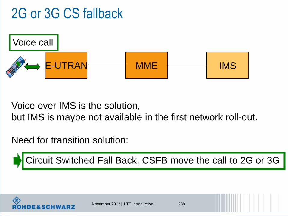
November 2012 | LTE Introduction | 288
2G or 3G CS fallback
E-UTRAN MME IMS
Voice call
Voice over IMS is the solution,
but IMS is maybe not available in the first network roll-out.
Need for transition solution:
Circuit Switched Fall Back, CSFB move the call to 2G or 3G

November 2012 | LTE Introduction | 289
CSFB issues and questions
UE E - UTRAN MME LTE Uu S 1 - MME
GERAN
UTRAN
Um
Uu
SGSN
MSC Server
SGs
Gs
A
Iu - cs
Gb
Iu - ps
S 3
•Is it a handover command or a command to redirect to a new RAN ? i.e.
the UE selects the target cell or the EUTRAN commands the target cell
•Is there any information about the target RAN available (SysInfo)?
•Is there a packet data connection PDN active or not?
•Will the PDN be suspended or continued in the target RAN?
•Will the UE re-initiate the PDN or continue?
Handover or
Redirection?
Target cell
assigned or
selected by UE?

November 2012 | LTE Introduction | 290
CS fallback options to UTRAN and GERAN
Feature
group
index, UE
indicates
CSFB
support

November 2012 | LTE Introduction | 291
CS fallback to 1xRTT
E-UTRAN
MME
Serving/PDN GW
SGi
1xRTT CS Access
1xRTT MSC
1xCS IWS
S102
S11 S1-MME
S1-U
A1
A1
Tunnelled 1xRTT messages
1xCS CSFB
UE
1xCS CSFB
UE
S102 is the
reference point
between MME and
1xCS interworking
solution
Tunneling of
messages between
1xRTT MSC and UE

November 2012 | LTE Introduction | 292
CS fallback to 1xRTT

November 2012 | LTE Introduction | 293
CS fallback - arguments
l E-UTRAN and GERAN/UTRAN coverage must overlap
l No E-UTRAN usage for voice
l No changes on EPS network required
l Gs interface MSC-SGSN not widely implemented
l Increased call setup time
l No simultaneous voice + data if 2G network/UE does not support DTM
l SMS can be used without CS fallback, via E-UTRAN

November 2012 | LTE Introduction | 294
l Call setup delay
l Call drop due to handover
l Blind hand-over is used for CSFB
l Data applications are interupted
l Legacy RAN coverage needed
Why not CSFB?
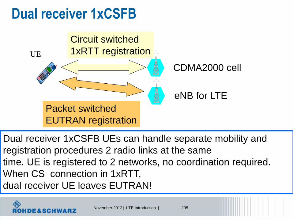
November 2012 | LTE Introduction | 295
Dual receiver 1xCSFB
UE
eNB for LTE
CDMA2000 cell
Circuit switched
1xRTT registration
Packet switched
EUTRAN registration
Dual receiver 1xCSFB UEs can handle separate mobility and
registration procedures 2 radio links at the same
time. UE is registered to 2 networks, no coordination required.
When CS connection in 1xRTT,
dual receiver UE leaves EUTRAN!

November 2012 | LTE Introduction | 296
SV-LTE: Simultaneous CDMA200 + LTE
UE
eNB for LTE
CDMA2000 cell
Circuit switched
1xRTT connection
Packet switched
EUTRAN connection
Simultaneous Voice UEs can handle 2 radio links at the same
time. UE is registered to MME and CDMA2K independently

November 2012 | LTE Introduction | 297
OTT – over the top
S-GW P-GW
Evolved nodeB UE
Evolved Packet Core
EUTRAN
PDN
Application
Voice call as application, e.g. Skype, Google talk, …

November 2012 | LTE Introduction | 298
OTT – over the top - arguments
S-GW P-GW
Evolved nodeB UE
Evolved Packet Core
EUTRAN
PDN
Application
•Propietary solution, needs to be implemented in UE and AS
•Already implemented in computer networks – known application
•Support has to be accepted by operator
•No Inter-RAT handover is possible

November 2012 | LTE Introduction | 299
SMS transfer in LTE
PHYSICAL LAYER
Medium Access Control
MAC
Radio Resource Control
RRC
Contr
ol &
Measure
ments
Radio Link Control
RLC
Packet Data Convergence
PDCP
EMM ESM User plane
Transport channels
Logical channels
Radio Bearer
Encapsulate SMS in NAS
Control message->
SMS over SG
Send SMS over IMS
Using IP protocol
SMS over IMS

November 2012 | LTE Introduction | 300
Single Radio Voice Call Continuity
Problem: in first network roll-out,
there is no full LTE coverage. How to
keep call active?
=> SRVCC

November 2012 | LTE Introduction | 301
Single Radio Voice Call Continuity
eNodeB = EUTRAN VoLTE call
time
VoIP in PS mode
Voice call in CS mode
NodeB = UTRAN
NodeB = UTRAN
Handover to UTRAN
Radio Bearer reconfiguration:
PS to CS mode

November 2012 | LTE Introduction | 302
Handover – what to discuss?
UE
eNodeB
EUTRAN cell
Redirection command?
UTRAN cell(s)?
Will the UE initiate the
change? -> re-selection
Will the network initiate
the change? ->
redirection or handover
Mandatory
for UE
supporting
CSFB
UE reads
SysInfo
Handover command?
GERAN cell(s)?
NW sends
SysInfo of
Target?
CDMA2K cell(s)?

November 2012 | LTE Introduction | 303
Handover aspects – what to discuss?
l Some keywords that appear – and to be clarified in next
slides:
l Handover?
l Cell reselection?
l Cell change order?
l Redirection?
l Network assisted cell change, NACC?
l Circuit switched fallback, CS fallback?

November 2012 | LTE Introduction | 304
Mobility between LTE and WCDMA/GSM Radio Access Aspects
Handover
CELL_PCH
URA_PCH
CELL_DCH
UTRA_Idle
E-UTRA
RRC_CONNECTED
E-UTRA
RRC_IDLE
GSM_Idle/GPRS
Packet_Idle
GPRS Packet
transfer mode
GSM_Connected
Handover
Reselection Reselection
Reselection
Connection
establishment/release
Connection
establishment/release
Connection
establishment/release
CCO,
Reselection
CCO with
optional
NACC
CELL_FACH
CCO, Reselection

November 2012 | LTE Introduction | 305
Redirection to UMTS
UE
eNodeB
EUTRAN cell
RRC connection release message
with RedirectedCarrierInfo to
UTRAN
NodeB(s)
UTRAN cell(s)
UE will search for
suitable cell on
UARFCN and initiate
CS connection
RRC connection release with redirection without SysInfo
Mandatory
for UE
supporting
CSFB
UE reads
SysInfo
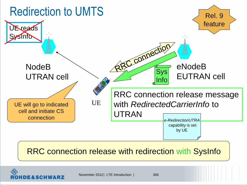
November 2012 | LTE Introduction | 306
Redirection to UMTS
UE
eNodeB
EUTRAN cell
RRC connection release message
with RedirectedCarrierInfo to
UTRAN
NodeB
UTRAN cell
UE will go to indicated
cell and initiate CS
connection
RRC connection release with redirection with SysInfo
e-RedirectionUTRA
capability is set
by UE
Sys
Info
Rel. 9
feature UE reads
SysInfo

November 2012 | LTE Introduction | 307
Redirection to GERAN
UE
eNodeB
EUTRAN cell
RRC connection release message
with RedirectedCarrierInfo to
GSM
BTS(s)
GSM cell(s)
UE will search for
suitable cell on ARFCN
and initiate CS
connection
RRC connection release with redirection without SysInfo
Mandatory
for UE
supporting
CSFB

November 2012 | LTE Introduction | 308
Redirection to GERAN
UE
eNodeB
EUTRAN cell
RRC connection release message
with RedirectedCarrierInfo to
GSM
UE will go to indicated
cell and initiate CS
connection
RRC connection release with redirection with SysInfo
e-RedirectionUTRA
capability is set
by UE
Sys
Info
Rel. 9
feature
BTS(s)
GSM cell(s)

November 2012 | LTE Introduction | 309
Handover to UMTS: Packet switched handover
UE
eNodeB
EUTRAN cell
MobilityFromEUTRACommand message
with purpose indicator = handover
to UTRAN
EUTRAN contains targetRATmessagecontainer,
= Inter-RAT info about target cell
NodeB(s)
UTRAN cell(s)
UE will select target cell
on UARFCN and
continue PS connection
Packet Switched handover to UTRAN

November 2012 | LTE Introduction | 310
Inter-RAT Handover to GERAN: cell change order
UE
eNodeB
EUTRAN cell
MobilityFromEUTRACommand message
with purpose indicator = Cell Change Order
to GPRS
BTS(s)
GPRS cell(s)
UE will search for
suitable cell on ARFCN
and re-initiate PS
connection
Packet Switched cell change order to GPRS without NACC
(network assisted cell change)
Mandatory
for UE
supporting
CSFB
PS connection will be suspended

November 2012 | LTE Introduction | 311
Inter-RAT Handover to GERAN: cell change order
UE
eNodeB
EUTRAN cell
MobilityFromEUTRACommand message
with purpose indicator = Cell Change Order
to GPRS
BTS
GPRS cell
UE will search for
suitable cell on ARFCN
and initiate PS
connection
Packet Switched cell change order to GPRS with NACC
(network assisted cell change)
Mandatory
for UE
supporting
CSFB
Sys
Info
PS connection will be suspended
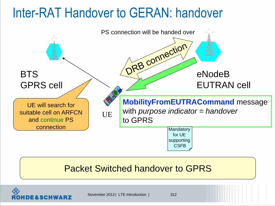
November 2012 | LTE Introduction | 312
Inter-RAT Handover to GERAN: handover
UE
eNodeB
EUTRAN cell
MobilityFromEUTRACommand message
with purpose indicator = handover
to GPRS
BTS
GPRS cell
UE will search for
suitable cell on ARFCN
and continue PS
connection
Packet Switched handover to GPRS
Mandatory
for UE
supporting
CSFB
PS connection will be handed over

November 2012 | LTE Introduction | 313
LTE-RTT Handover
Circuit Switched Fallback, CSFB
Overview

November 2012 | LTE Introduction | 314
CS fallback to 1xRTT
E-UTRAN
MME
Serving/PDN GW
SGi
1xRTT CS Access
1xRTT MSC
1xCS IWS
S102
S11 S1-MME
S1-U
A1
A1
Tunnelled 1xRTT messages
1xCS CSFB
UE
1xCS CSFB
UE
S102 is the
reference point
between MME and
1xCS interworking
solution
Tunneling of
messages between
1xRTT MSC and UE

November 2012 | LTE Introduction | 315
CS fallback to 1xRTT
UE
eNodeB
EUTRAN cell
RRC connection release message
with RedirectedCarrierInfo to
1xRTT
1xRTT cell(s)
UE will search for
suitable cell on
UARFCN and initiate
CS connection
RRC connection release with redirection without SysInfo
Mandatory
for UE
supporting
CSFB
to 1xRTT
MME
CSFB Info
CSFB to 1xRTT
Enhancement: UE can pre-register in 1xRTT network

November 2012 | LTE Introduction | 316
CS fallback to 1xRTT
MobilityFromEUTRACommand
UE EUTRAN
HandoverFromEUTRAPreparationRequest
UE EUTRAN
ULHandoverPreparationTransfer
UE EUTRAN
enhanced 1xCSFB (e1xCSFB)
1) Prepare for
handover,
search for
1xRTT
2) Info about
1xRTT ->
tunnelled via
S102
3) Includes
1xRTT channel
assignment
Time flow
Enhancement: UE can pre-register in 1xRTT network

November 2012 | LTE Introduction | 317
CS fallback to 1xRTT
MobilityFromEUTRACommand
UE EUTRAN
HandoverFromEUTRAPreparationRequest
UE EUTRAN
ULHandoverPreparationTransfer
UE EUTRAN
enhanced 1xCSFB (e1xCSFB) + concurrent HRPD handover
1) Prepare for
handover,
search for
1xRTT + HRPD
2) Trigger 2
messages with
info about
1xRTT + HRPD
3) Redirection
to 1xRTT and
handover to
HRPD
Time flow
Enhancement: UE can pre-register in 1xRTT network
ULHandoverPreparationTransfer
UE EUTRAN
November 2012 | LTE Introduction | 318
LTE-eHRPD Handover
Overview
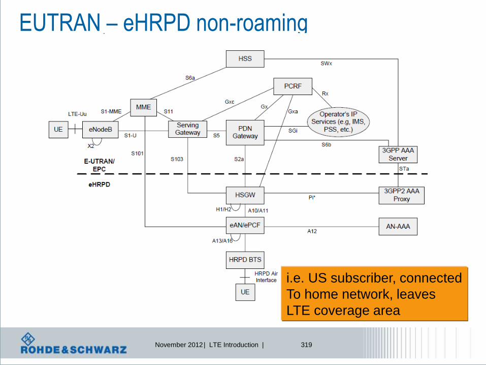
November 2012 | LTE Introduction | 319
EUTRAN – eHRPD non-roaming
i.e. US subscriber, connected
To home network, leaves
LTE coverage area

November 2012 | LTE Introduction | 320
EUTRAN – eHRPD, roaming case
i.e. European subscriber
visiting US, connected to roaming
network and leaving LTE
coverage area

November 2012 | LTE Introduction | 321
Mobility between LTE and HRPD Radio Access Aspects
HRPD active to EUTRAN is
always cell reselection
(via RRC idle)
No handover to
EUTRAN

November 2012 | LTE Introduction | 322
3 Step Procedure
E-UTRAN needs
to decide, that
HO to HRPD
is required
HO preparation
Connection Request
issued by UE to
HRPD, HRPD prepares
for the arrival of the UE
HO execution
Traffic Channel Assignment
command is delivered
to UE, re-tune radio to
HRPD channel, acquire
HRPD channel, session
configuration
UE attached
to E-UTRAN
Ability of pre-
registration is
indicated
on PBCCH
Pre-registration
• Reduces time for cell re-selection or handover
• Reduces risk of radio link failure
Video over LTE Testing the next step in the end user experience

November 2012 | LTE Introduction | 324
Node B
Internet
SGW PGW
MME PCRF
EPC / IMS
Node B
Impact due to
l Multipath propagation
l Speed
l …
Impact due to
l Packet delay
l Packet jitter
l Packet loss
l …
Introduction Network view

November 2012 | LTE Introduction | 325
l Main use cases from a test engineer (operator, manufacturer) perspective:
l Exploring the performance of mobile equipment from the end user perspective
l Measuring E2E throughput with realistic radio conditions
l Evaluating mobility performance
Introduction Testing real life conditions in the lab
l Important aspect for end user perspective: Error free video reception
R&S®CMW500
emulates LTE
network
R&S®AMU200
baseband fader
simulates real life
radio conditions
Contest SW
provides
automation
and reporting
capabilities
CMW-PQA

November 2012 | LTE Introduction | 326
Receiver
Video transmission over LTE The video processing chain and possible sources for video degradation
Encoder
Uncompressed video
SDI
SMPTE249/292/424
Redundant
information (static
image parts) and
irrelevant data
(details) is omitted
Decoder TX RX Video processor
Output on
screen Restoring the video
information; i.e. the
picture sequence
including redundant
data
Scaling and
conversion to output
format
Transmission
link
(IP, cellular,
broadcast, etc.)
• Encoding artifacts
(blocking)
• Video / audio delay
• Buffer rules are
violated
Impairments on the
transmission link
can cause loss of
information despite
active error
correction
The decoder is usually the less
critical component. But in
conjunction with the video
processor, errors during the
conversion process (e.g. de-
interlacing) are possible

November 2012 | LTE Introduction | 327
Video transmission over LTE Testing real life conditions in the lab
PC
Contest
TC Control
Video
via MHL
or HDMI
RF
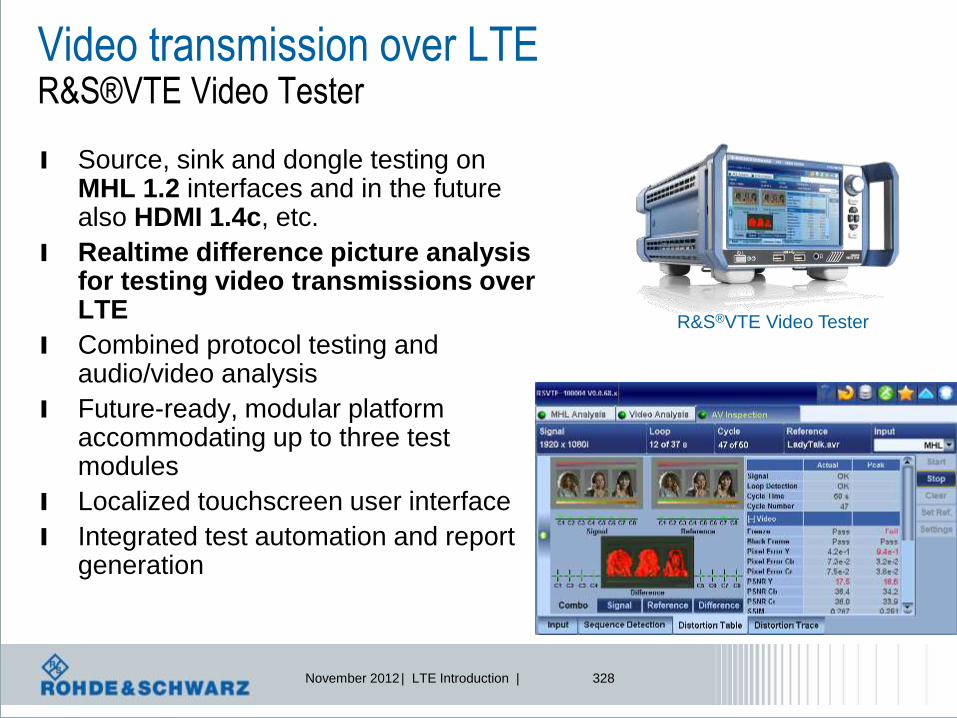
November 2012 | LTE Introduction | 328
Video transmission over LTE R&S®VTE Video Tester
l Source, sink and dongle testing on MHL 1.2 interfaces and in the future also HDMI 1.4c, etc.
l Realtime difference picture analysis for testing video transmissions over LTE
l Combined protocol testing and audio/video analysis
l Future-ready, modular platform accommodating up to three test modules
l Localized touchscreen user interface
l Integrated test automation and report generation
R&S®VTE Video Tester

November 2012 | LTE Introduction | 329
Summary
l Video and voice are important services gaining momentum for
the fastest developing radio access technology ever - LTE
l Beside LTE functionality, testing voice/video quality is
essential to judge a good receiver implementation
l R&S provides you with profound expertise and
test solutions on both aspects
l Complete LTE test portfolio ranging from early R&D via IOT
and field testing until conformance and production
l Supplier of a complete range of TV broadcasting transmission,
monitoring and measurement equipment

November 2012 | LTE Introduction | 330
There will be enough topics
for future trainings
Thank you for your attention!
Comments and questions welcome!