LTA - Materials & Workmanship Specification for Civil & Structural Works (Jun 2010)
572
Engineering Group Document E/GD/09/104/A1 M&W for Civil & Structural Works Sheet 1 of 50 ENGINEERING GROUP MATERIALS & WORKMANSHIP SPECIFICATION FOR CIVIL & STRUCTURAL WORKS E/GD/09/104/A1 Controlled Document A1 Jun 2010 Chua Swee Foon AgDyM Wen Dazhi DDCDE Neo Bian Hong D(Desg) Paul Fok GDE Addition of clauses 10.3.2.2, 10.3.2.5, 10.3.2.6 & 10.3.4. Reference renamed from PED/DD/K9/104/A9. Rev Date Editor Custodian Approved By Approved for Implementation Description of Revision
-
Upload
lwinoo2435 -
Category
Documents
-
view
1.147 -
download
59
Transcript of LTA - Materials & Workmanship Specification for Civil & Structural Works (Jun 2010)
Engineering Group Document E/GD/09/104/A1 M&W for Civil & Structural Works Sheet 1 of 50
ENGINEERING GROUP
MATERIALS & WORKMANSHIP SPECIFICATION
FOR CIVIL & STRUCTURAL WORKS
E/GD/09/104/A1
Controlled Document
A1 Jun
2010
Chua Swee Foon
AgDyM Wen Dazhi
DDCDE Neo Bian Hong
D(Desg) Paul Fok
GDE
Addition of clauses 10.3.2.2, 10.3.2.5, 10.3.2.6 & 10.3.4. Reference renamed from PED/DD/K9/104/A9.
Rev Date Editor Custodian Approved By Approved for Implementation
Description of Revision

Engineering Group Document E/GD/09/104/A1 M&W for Civil & Structural Works Sheet 2 of 50
C O N T E N T S
Chapter 1 GENERAL Chapter 2 DEMOLITION, SITE CLEARANCE AND HOARDING Chapter 3 SURVEY AND SETTING OUT Chapter 4 EARTHWORKS Chapter 5 PILING Chapter 6 DIAPHRAGM WALL CONSTRUCTION Chapter 7 SOIL IMPROVEMENT WORKS Chapter 8 TEMPORARY WORKS Chapter 9 INSTRUMENTATION AND MONITORING Chapter 10 ROADWORKS Chapter 11 CONCRETE AND REINFORCEMENT Chapter 12 STRUCTURAL STEELWORKS Chapter 13 ABOVE-GROUND STRUCTURES Chapter 14 WATERPROOFING FOR STRUCTURES Chapter 15 BEARINGS AND MOVEMENT JOINTS Chapter 16 BORED TUNNELS AND RELATED WORKS Chapter 17 SPRAYED CONCRETE LINING FOR TUNNELS Chapter 18 PIPEWORK AND PUMPS Chapter 19 DRAINAGE WORKS Chapter 20 SEWERAGE AND SANITARY PLUMBING Chapter 21 WATER SERVICES Chapter 22 (Not Used) Chapter 23 ELECTRICAL WORKS
Engineering Group Document E/GD/09/104/A1 M&W for Civil & Structural Works Sheet 3 of 50
C O N T E N T S (Cont’d)
Chapter 24 BRACKETS AND CAST-IN DUCTS FOR CABLES AND PIPES Chapter 25 STRAY CURRENT CONTROL AND TOUCH VOLTAGE PROTECTION Chapter 26 TELEPHONE INSTALLATIONS Chapter 27 (Not Used) Chapter 28 (Not Used) Chapter 29 TURFING AND PLANTING
Engineering Group Document E/GD/09/104/A1 M&W for Civil & Structural Works Sheet 4 of 50
CHAPTER 1
GENERAL
1.1 GENERAL 1.2 STANDARDS AND CODES OF PRACTICE
1.3 TRADE NAMES
1.4 SAMPLES OF MATERIALS AND WORKMANSHIP
1.5 INSPECTION AND TESTING
1.6 SITE RECORDS

Engineering Group Document E/GD/09/104/A1 M&W for Civil & Structural Works Sheet 5 of 50
CHAPTER 2
DEMOLITION, SITE CLEARANCE AND HOARDING
2.1 GENERAL 2.2 SITE HOARDING 2.3 DEMOLITION 2.3.1 Notice of Demolition 2.3.2 Method of Demolition 2.3.3 Protection of Adjacent Structures 2.3.4 Utilities and Services 2.3.5 Grubbing of Foundations 2.4 CONFINING OF WORKS WITHIN THE SITE 2.5 TREES, BUSHES, HEDGES, ETC. 2.6 TURF AND TOPSOIL 2.7 DUMPING OF DEBRIS, ETC.
Engineering Group Document E/GD/09/104/A1 M&W for Civil & Structural Works Sheet 6 of 50
CHAPTER 3
SURVEY AND SETTING OUT
3.1 GENERAL 3.2 SURVEY CONTROL 3.2.1 Survey Markers 3.2.2 Control Observation, Adjustment and Presentation 3.3 GENERAL SETTING OUT
3.4 TUNNEL SHIELD PRE-LAUNCH SURVEY 3.5 TUNNEL SURVEY DURING CONSTRUCTION 3.6 WRIGGLE SURVEY 3.7 MONITORING SURVEYS
Engineering Group Document E/GD/09/104/A1 M&W for Civil & Structural Works Sheet 7 of 50
CHAPTER 4
EARTHWORKS
4.1 GENERAL 4.2 CLASSIFICATION OF EARTHWORK MATERIAL 4.3 EARTHWORK GENERAL 4.4 EXCAVATION GENERAL 4.5 CUTTINGS AND CUT SLOPES 4.5.1 General 4.5.2 Shotcrete To Exposed Slopes 4.6 REMOVAL OF ROCKS AND OTHER BLASTING 4.7 EXCAVATION OF PITS AND TRENCHES 4.8 BACKFILLING OF PITS AND TRENCHES 4.9 FILLING GENERAL 4.10 FOUNDATION FOR FILLS 4.11 EMBANKMENTS AND FILL SLOPES 4.12 COMPACTION OF FILL 4.12.1 General 4.12.2 Compaction by Mechanical Plant 4.13 FILL ADJACENT TO BRIDGE ABUTMENTS, CULVERTS, RETAINING
WALLS AND UNDERGROUND STRUCTURES 4.14 PREPARATION OF RAIL TRACK FORMATION SURFACE 4.15 PREPARATION FOR CULTIVATION WITH SPOT AND CLOSE TURFING 4.16 GEOTEXTILE

Engineering Group Document E/GD/09/104/A1 M&W for Civil & Structural Works Sheet 8 of 50
CHAPTER 5
PILING
5.1 GENERAL REQUIREMENTS FOR PILING WORK 5.1.1 General 5.1.2 Tolerances 5.1.2.1 Setting out 5.1.2.2 Position 5.1.2.3 Verticality 5.1.2.4 Rake 5.1.3 Forcible Correction 5.1.4 Replacement of Piles 5.1.5 Preliminary Pile Testing 5.1.6 Piling near Recently Cast Piles 5.1.7 Piling Programme 5.1.8 Records 5.1.9 As-Built Details 5.2 REQUIREMENTS FOR REINFORCED CONCRETE IN PILES 5.2.1 General 5.2.2 Cast Insitu Concrete Piles 5.2.2.1 General 5.2.2.2 Workability of Concrete 5.2.2.3 Compaction 5.2.2.4 Placing and Cleaning of Reinforcement 5.2.2.5 Placing Concrete in Dry Shafts 5.2.2.6 Placing Concrete Under Water or Under Drilling Fluid 5.2.2.7 Trimming of Pile Head 5.2.2.8 Monitoring of Concrete Level during Pile Casting 5.2.3 Precast Reinforced & Prestressed Concrete Piles 5.2.3.1 General 5.2.3.2 Tolerances in Pile Dimensions 5.2.3.3 Reinforcement in Piles 5.2.3.4 Formwork for Piles 5.2.3.5 Casting of Piles 5.2.3.6 Cutting Off Pile Heads
5.3 BORED CAST IN-SITU PILES 5.3.1 Boring 5.3.1.1 Temporary Casings 5.3.1.2 Stability of Pile Excavation Using Drilling Fluid 5.3.1.3 Spillage and Disposal 5.3.1.4 Pumping from Pile Excavation 5.3.1.5 Continuity of Construction 5.3.1.6 Cleanliness of Pile Bases 5.3.1.7 Inspection 5.3.1.8 Pile Verticality 5.3.2 Drilling Fluid 5.3.3 Determination of Bored Pile Length

Engineering Group Document E/GD/09/104/A1 M&W for Civil & Structural Works Sheet 9 of 50
CHAPTER 5
PILING (Cont’d)
5.3.4 Concreting and Extraction of Casing 5.3.4.1 Workability of Concrete 5.3.4.2 Concrete Level 5.3.4.3 Water Levels 5.3.5 Temporary Backfilling 5.3.6 Debonding of Bored Piles 5.4 DRIVEN PILES 5.4.1 Marking of Driven Piles 5.4.2 Handling and Pitching of Driven Piles 5.4.3 Strength of Piles 5.4.4 Pile Shoes 5.4.5 Leaders and Trestles 5.4.6 Performance of Driving Equipment 5.4.7 Length of Piles 5.4.8 Driving Procedure and Redrive Checks 5.4.9 Final Set 5.4.10 Driving Sequence and Risen Piles 5.4.11 Preboring 5.4.12 Jetting 5.5 STEEL PILES 5.5.1 Pile Sections and Pile Dimensions 5.5.2 Straightness of Piles 5.5.3 Fabrication of Piles 5.5.4 Matching of Pile Lengths 5.5.5 Inspection and Test Certificates 5.5.6 Welding 5.5.7 Fabrication of Piles on Site 5.5.8 Strengthening of Piles 5.5.9 Longitudinal Welded Piles 5.5.9.1 Welded Tube Piles 5.5.9.2 Welded Box Piles and Proprietary Sections 5.5.9.3 Weld Check on Welded Piles 5.5.10 Spirally Welded Piles 5.5.11 Pile Coatings 5.5.12 Handling and Storage of Piles 5.5.13 Preparation of Pile Heads 5.6 TIMBER PILES 5.6.1 Pressure Treated Timber Piling 5.6.1.1 Pile Material 5.6.1.2 Preservative Treatment 5.6.1.2.1 Composition 5.6.1.2.2 Application 5.6.1.2.3 Penetration
Engineering Group Document E/GD/09/104/A1 M&W for Civil & Structural Works Sheet 10 of 50
CHAPTER 5
PILING (Cont’d)
5.6.1.2.4 Retention 5.6.1.2.5 Plugging Sample Holes 5.6.1.3 Lifting and Stacking 5.6.1.4 Equipment and Plant 5.6.1.5 Tolerance, Straightness and Joints 5.6.1.6 Pile Position 5.6.1.7 Driving of Timber Piles 5.6.1.8 Replacement of Defective Piles 5.6.1.9 Cut Off Level of Piles 5.6.1.10 Load Testing of Timber Piles 5.6.1.11 Interpretation of Test Results 5.6.1.12 Failure of Pile under Test Loading 5.6.1.13 Warranty 5.6.2 Bakau Piling (Indigenous Timber Piles) 5.6.2.1 Pile Material 5.6.2.2 Pile Lengths 5.6.2.3 Pile Diameter 5.6.2.4 Examination of Piles Delivered 5.6.2.5 Protection of Pile Heads 5.6.2.6 Joints 5.6.2.7 Pile Driving Equipment 5.6.2.8 Driving 5.6.2.9 Pile Replacement 5.7 PILE LOAD TESTING 5.7.1 General 5.7.2 Definitions 5.7.3 Safety Precautions 5.7.3.1 Personnel 5.7.3.2 Kentledge 5.7.3.3 Tension Pile and Ground Anchors 5.7.3.4 Testing Equipment 5.7.4 Construction of a Preliminary Test Pile 5.7.4.1 Notice of Construction 5.7.4.2 Method of Construction 5.7.4.3 Instrumentation for Preliminary Piles 5.7.4.4 Boring or Driving Record 5.7.4.5 Cut-off Level 5.7.4.6 Pile Head Construction 5.7.4.6.1 Compression Test 5.7.4.6.2 Tension Test 5.7.5 Preparation of a Working Pile to be Tested 5.7.6 Concrete Test Cubes 5.7.7 Reaction Systems 5.7.7.1 Compression Tests 5.7.7.2 Tension Tests
Engineering Group Document E/GD/09/104/A1 M&W for Civil & Structural Works Sheet 11 of 50
CHAPTER 5
PILING (Cont’d)
5.7.7.3 Working Piles 5.7.7.4 Spacing 5.7.7.5 Adequate Reaction 5.7.7.6 Care of Piles 5.7.7.7 Loading Arrangement 5.7.8 Equipment for Applying Load 5.7.9 Measurement of Load 5.7.10 Adjustability of Loading Equipment 5.7.11 Measuring Movement of Pile Heads 5.7.11.1 Levelling Method for Maintained Load Test Only 5.7.11.2 Independent Reference Frame 5.7.11.3 Reference Wires 5.7.11.4 Other Methods 5.7.11.5 Calibration of Dial Gauges 5.7.12 Protection of Testing Equipment from Weather 5.7.13 Supervision 5.7.13.1 Notice of Test 5.7.13.2 Records 5.7.14 Test Procedures 5.7.14.1 Ultimate Load Test by Maintained Load 5.7.14.2 Working Load Test by Maintained Load 5.7.14.3 Requirements for Working Load Test 5.7.14.4 Continuity Testing 5.7.15 Testing Criteria 5.7.15.1 Failure of Piles 5.7.15.2 Faulty Pile Tests 5.7.16 Presentation of Results 5.7.16.1 Results to be Submitted 5.7.16.2 Schedule of Recorded Data 5.7.16.3 Presentation of Graphical Results 5.7.16.4 Submission of Results to Borehole Information System (BIS) 5.7.17 Removal of Ground Anchors and Cutting-Off of Temporary Piles 5.7.18 Dynamic Load Testing of Piles Using Stress Wave Measurements 5.7.18.1 Testing Requirements 5.7.18.2 Method of Testing 5.7.18.3 Results of the Test 5.7.19 Lateral Load Test 5.7.19.1 Lateral Load Test on Preliminary Piles 5.7.19.2 Lateral Load Tests on Working Piles 5.7.19.3 Abandonment of Lateral Load Tests 5.7.19.4 Failure of Lateral Load Tests on Working Piles 5.7.19.5 Remedial Works for Excessive Deflections

Engineering Group Document E/GD/09/104/A1 M&W for Civil & Structural Works Sheet 12 of 50
CHAPTER 5
PILING (Cont’d)
5.8 INTEGRITY TESTS 5.8.1 General 5.8.2 Proof Coring 5.8.3 Non-Destructive Testing 5.8.3.1 Sonic Logging Tests 5.8.3.1.1 Sonic Logging Tubes 5.8.3.1.2 Sonic Coring 5.8.3.1.3 Sonic Logging Equipment 5.8.3.1.4 Test Procedure 5.8.3.1.5 Analysis of Test Results 5.8.3.1.6 Submission of Results 5.8.3.1.7 Anomalous Sonic Logging Test Results 5.8.3.1.8 Grouting of Pile After Testing 5.8.3.2 Vibration Test 5.8.3.2.1 Preparation of Pile Heads 5.8.3.2.2 Testing 5.8.3.2.3 Analysis of Test Results 5.8.3.2.4 Anomalous Vibration Test Results 5.8.3.3 Modified Shock Test 5.8.3.3.1 Preparation of Pile Heads 5.8.3.3.2 Testing 5.8.3.3.3 Analysis of Results 5.8.3.3.4 Submission of Results 5.8.3.3.5 Anomalous Modified Shock Test Results 5.8.3.4 Simple Shock Test 5.8.3.4.1 Preparation of Pile Heads 5.8.3.4.2 Testing 5.8.3.4.3 Analysis of Test Results 5.8.3.4.4 Submission of Results 5.8.3.4.5 Anomalous Simple Shock Test Results 5.8.3.5 Low Strain Impact Test APPENDIX 5.1

Engineering Group Document E/GD/09/104/A1 M&W for Civil & Structural Works Sheet 13 of 50
CHAPTER 6
DIAPHRAGM WALL CONSTRUCTION
6.1 GENERAL
6.2 METHOD STATEMENT
6.3 TRENCH AND GUIDEWALL STABILITY
6.4 LEVELS OF WORK
6.5 TOLERANCES
6.6 HEADROOM
6.7 REINFORCEMENT
6.8 WELDING OF REINFORCEMENT
6.9 CONCRETE
6.10 BENTONITE
6.11 TESTING BENTONITE SLURRY
6.12 STORAGE OF BENTONITE
6.13 ALTERNATIVE MATERIALS
6.14 TREMIE CONCRETE
6.15 TEST CUBES
6.16 BACKFILLING
6.17 STOP ENDS
6.18 INSERTS
6.19 MONITORING
6.20 SAFETY AND EMERGENCY PROCEDURES
6.21 SITE CLEANLINESS
6.22 OBSTRUCTIONS
Engineering Group Document E/GD/09/104/A1 M&W for Civil & Structural Works Sheet 14 of 50
CHAPTER 6
DIAPHRAGM WALL CONSTRUCTION (Cont’d)
6.23 DISPOSAL OF SPOIL
6.24 JOINTS
6.25 CLEANING
6.26 RECORDS
6.27 DISPOSAL OF SLURRY
6.28 CUTTING DOWN OF DIAPHRAGM WALLS
Engineering Group Document E/GD/09/104/A1 M&W for Civil & Structural Works Sheet 15 of 50
CHAPTER 7
SOIL IMPROVEMENT WORKS
7.1 GENERAL
7.2 SOIL IMPROVEMENT USING PREFABRICATED DRAINS 7.2.1 Prefabricated Drains 7.2.2 Method Statement 7.2.3 Installation of Drains 7.2.4 Records of Prefabricated Drain Installation Works 7.2.5 Sand Blanket 7.2.6 Surcharge Embankment Build-Up and Removal 7.2.6.1 Fill for Surcharge Embankment 7.2.6.2 Surcharge Embankment 7.2.6.3 Instrumentation and Monitoring 7.2.6.4 Removal of Surcharge Embankment 7.3 SOIL IMPROVEMENT USING JET GROUTING 7.3.1 Method Statement for Jet Grouting 7.3.2 Jet Grouting Trail 7.3.3 Drilling and Grouting 7.3.4 Records 7.3.5 Quality Control 7.3.6 Control of Ground, Building and Utility Movements 7.4 DEEP SOIL MIXING (DSM) 7.4.1 Method Statement for DSM 7.4.2 DSM Trial 7.4.3 Installation of DSM Columns 7.4.4 Records 7.4.5 Quality Control 7.4.6 Control of Ground, Building and Utility Movements 7.5 LIME OR CHEMICO-LIME PILES 7.5.1 Method Statement for Lime Piles 7.5.2 Lime Pile Trial 7.5.3 Installation of Lime Piles 7.5.4 Records 7.5.5 Quality Control 7.5.6 Control of Ground, Building and Utility Movements
7.6 DYNAMIC COMPACTION 7.6.1 Method Statement for Dynamic Compaction 7.6.2 Dynamic Compaction Trial 7.6.3 Conducting Dynamic Compaction 7.6.4 Records 7.6.5 Quality Control 7.6.6 Control of Ground, Building and Utility Movements and Vibration

Engineering Group Document E/GD/09/104/A1 M&W for Civil & Structural Works Sheet 16 of 50
CHAPTER 8
TEMPORARY WORKS 8.1 GENERAL 8.2 DESIGN AND SUPERVISION OF TEMPORARY WORKS 8.3 FALSEWORK 8.4 SCAFFOLDING AND STAGING 8.5 TEMPORARY DECKING 8.6 GROUND ANCHORS 8.7 SHEET PILING 8.8 STRUTS & WALINGS 8.9 DEWATERING 8.10 REMOVAL OF TEMPORARY WORKS

Engineering Group Document E/GD/09/104/A1 M&W for Civil & Structural Works Sheet 17 of 50
CHAPTER 9
INSTRUMENTATION AND MONITORING
9.1 OBJECTIVES 9.2 SUBMISSIONS 9.3 INSTRUMENTATION PERSONNEL AND RESOURCES 9.4 INSTRUMENTS AND MONITORING SYSTEMS 9.5 INSTALLATION AND MAINTENANCE OF INSTRUMENTS 9.6 INSTRUMENT READING AND RECORDS 9.7 RECORDING EQUIPMENT AND ANCILLARIES 9.7.1 Instrumentation Cabling 9.7.2 Terminal Boxes for Remote Readout 9.7.3 Remote Readout Facilities 9.7.4 Data Loggers 9.8 SETTLEMENT POINTS 9.9 DEEP LEVELLING DATUMS 9.10 ELECTROLEVEL BEAMS 9.10.1 System Requirements 9.10.2 Installation 9.11 INCLINOMETERS 9.11.1 General 9.11.2 Electrolevel Inclinometers (Remotely Read) 9.11.3 Inclinometers (Manually Read) 9.12 MAGNETIC EXTENSOMETERS 9.13 ROD EXTENSOMETERS 9.14 TAPE EXTENSOMETER 9.15 VIBRATING WIRE PIEZOMETERS 9.15.1 Installation in Boreholes Drilled from the surface 9.16 WATER STANDPIPES 9.17 TEMPERATURE SENSOR

Engineering Group Document E/GD/09/104/A1 M&W for Civil & Structural Works Sheet 18 of 50
CHAPTER 9
INSTRUMENTATION AND MONITORING (Cont’d)
9.18 STRAIN GAUGE 9.19 LOAD CELL 9.20 TELL-TALES 9.21 OPTICAL PLUMBING 9.22 AUTOMATICALLY LOGGED INSTRUMENTS 9.23 FIELD DATA 9.23.1 Reporting of Instrumentation Data to GDB 9.24 BOREHOLE INSTALLATION 9.24.1 Drilling 9.24.2 Records and Borehole Logs 9.24.3 Grouting 9.25 RECORDS AND REPORTING 9.25.1 General 9.25.2 Reporting 9.25.3 Monthly Reporting APPENDIX 9.1 APPENDIX 9.2

Engineering Group Document E/GD/09/104/A1 M&W for Civil & Structural Works Sheet 19 of 50
CHAPTER 10
ROADWORKS
10.1 GENERAL 10.2 EARTHWORKS 10.3 FLEXIBLE PAVEMENTS 10.3.1 Subgrade 10.3.1.1 Materials 10.3.1.2 Preparation of Subgrade 10.3.1.3 Protection of the Top of Subgrade 10.3.2 Sub-Base and Base 10.3.2.1 General 10.3.2.2 Sub-base 10.3.2.3 Plant-mixed Graded Granite Aggregate Base 10.3.2.4 Coarse Granite Aggregate (Crusher-run) Base 10.3.2.5 Recycled Concrete Aggregate (RCA) Base 10.3.2.6 Incineration Bottom Ash Sub-Base and Base 10.3.3 Asphaltic Concrete 10.3.3.1 Materials 10.3.3.2 Mix Design 10.3.3.2.1 Dense Mix 10.3.3.2.2 Porous Asphalt 10.3.3.2.3 Open Graded Asphalt 10.3.3.2.4 Stone Mastic Asphalt 10.3.3.3 Field Trial Mix by Contractor 10.3.3.4 Manufacture 10.3.3.5 Asphalt Laying 10.3.4 W3B(20R) and (B1(30R) Asphaltic Concrete with Reclaimed Asphalt
Pavement 10.3.4.1 Materials 10.3.4.2 Mix Design 10.3.4.3 Manufacture 10.3.4.4 Asphalt Laying 10.3.4.5 Quality Control and Quality Assurance 10.4 RIGID PAVEMENT 10.4.1 General 10.4.2 Materials 10.4.3 Construction 10.5 PAVEMENT MARKINGS 10.5.1 Temporary Pavement Marking 10.5.2 Thermoplastic Pavement Marking
Engineering Group Document E/GD/09/104/A1 M&W for Civil & Structural Works Sheet 20 of 50
CHAPTER 10
ROADWORKS (Cont’d) 10.6 ROAD AND RELATED FACILITIES CONSTRUCTION 10.6.1 Setting Out, Survey and Levelling 10.6.2 Materials and Colour Codes for Demarcation 10.6.3 Construction Tolerance 10.6.3.1 Surface Levels 10.6.3.2 Longitudinal Profile Measurement 10.6.3.3 Horizontal Alignment 10.6.4 Rectification of Levels 10.6.5 Vehicular Traffic on Pavement 10.6.6 Vehicular Impact Guardrail 10.6.6.1 Materials 10.6.6.2 Mechanical Properties 10.6.6.3 Thickness of Metal 10.6.6.4 Dimensions of Beam 10.6.6.5 Connections and Splices 10.6.6.6 Terminal Sections 10.6.6.7 Galvanising 10.6.6.8 Fabrication of Beam Elements and Terminal Sections 10.6.6.9 Marking 10.6.6.10 Testing 10.6.6.11 Posts 10.6.6.12 Installation 10.7 FOOTPATH EXPANSION JOINT FILLER 10.8 RETROREFLECTIVE SHEETING 10.8.1 Material 10.8.2 Test of Reflective Sheeting and Test Report 10.8.3 Warranty for the Reflective Sheetings and Vinyl Films 10.8.4 Transparent Process Inks 10.9 RAISED PAVEMENT MARKERS 10.9.1 Construction 10.9.2 Reflection 10.9.3 Effectiveness 10.9.4 Installation 10.10 PRECAST CONCRETE KERBS AND DIVIDERS

Engineering Group Document E/GD/09/104/A1 M&W for Civil & Structural Works Sheet 21 of 50
CHAPTER 11
CONCRETE AND REINFORCEMENT
11.1 CONCRETE MIX 11.1.1 General 11.2 CONSTITUENT MATERIALS OF CONCRETE 11.2.1 Cement 11.2.2 Aggregates 11.2.3 Water 11.2.4 Admixtures 11.3 REQUIREMENTS FOR DESIGN MIX 11.4 REQUIREMENTS FOR FRESH CONCRETE 11.5 REQUIREMENTS FOR HARDENED CONCRETE 11.6 PRODUCTION OF CONCRETE 11.6.1 General 11.6.2 Ready Mixed Concrete 11.7 CONTROL OF STRENGTH OF DESIGNED MIXES 11.8 TESTING AND SAMPLING OF FRESH CONCRETE 11.8.1 General 11.8.2 Rates of Sampling 11.8.3 Testing Plan 11.8.4 Compliance Requirements 11.8.5 Quantity of Concrete Represented by Strength Test Results 11.8.6 Action on Non-Compliance 11.8.7 Cement Content and Free-Water/Cement Ratio 11.8.8 Percentage Air Content 11.8.9 Workability of Concrete 11.9 SURFACE FINISH OF CONCRETE 11.9.1 General 11.9.2 Surface Finishes From Formwork Or Moulds 11.9.3 Surface Finishes Of Unformed Surfaces 11.9.4 Cementitious Spray Tile Finishes 11.10 CONSTRUCTION OF CONCRETE 11.10.1 Permissible Deviations for In-Situ and Precast Concrete Construction
and Manufactured Precast Reinforced Concrete Components 11.10.2 Load in Excess of Design Load 11.10.3 Construction Joints 11.10.4 Expansion, Contraction and other Movement Joints
Engineering Group Document E/GD/09/104/A1 M&W for Civil & Structural Works Sheet 22 of 50
CHAPTER 11
CONCRETE AND REINFORCEMENT (Cont’d) 11.10.5 Water Bar 11.10.6 Fixing Blocks, Brackets, Cast-In Bolt Holes, Chases 11.11 CONCRETING OF THICK SECTIONS 11.12 FORMWORK 11.13 REMOVAL OF FORMWORK 11.14 TRANSPORTING, PLACING AND COMPACTING OF CONCRETE 11.14.1 Method Statements 11.14.2 Transporting And Placing Of Concrete 11.14.3 Compaction 11.14.4 Protection Against Heavy Rainfall 11.14.5 Precautions During Hot Weather 11.14.6 Precautions For Thick Sections 11.14.7 Placing Concrete In Prestressed Concrete Work 11.14.8 Concreting Of Anchorage Recesses 11.15 CURING OF CONCRETE 11.15.1 Curing Methods 11.15.2 Accelerated Curing 11.16 REPAIR OF CRACKS IN REINFORCED CONCRETE 11.16.1 General 11.16.2 High Strength Cementitious Mortar 11.16.2.1 General 11.16.2.2 Materials 11.16.2.3 Submissions 11.16.2.4 Acceptance 11.16.2.5 Storage and Handling 11.16.2.6 Application 11.16.3 Epoxy Grouting 11.16.3.1 General 11.16.3.2 Submissions 11.16.3.3 Acceptance of Injection System 11.16.3.4 Quality Assurance: Packaging and Labelling 11.16.3.5 Quality Assurance: Storage and Handling 11.16.3.6 Materials: Epoxy Injection Resin 11.16.3.7 Materials: Surface Seal 11.16.3.8 Application: Preparation of Concrete Surface 11.16.3.9 Application: Injection Points 11.16.3.10 Application: Injection Sequence 11.16.3.11 Testing

Engineering Group Document E/GD/09/104/A1 M&W for Civil & Structural Works Sheet 23 of 50
CHAPTER 11
CONCRETE AND REINFORCEMENT (Cont’d) 11.16.3.12 Making Good 11.16.3.13 Safety 11.16.4 Polyurethane Grouting 11.16.4.1 General 11.17 PRECAST CONCRETE CONSTRUCTION 11.17.1 General 11.17.2 Handling, Storage and Transport 11.17.3 Protection 11.17.4 Assembly and Erection 11.17.5 Forming Structural Connection 11.18 REINFORCEMENT 11.18.1 General 11.18.2 Mechanical Couplers for Reinforcement Bars 11.18.3 Welding 11.19 TESTS ON HARDENED CONCRETE 11.19.1 Core Test 11.19.2 Check Test 11.19.3 Load Test 11.20 PRESTRESSING TENDONS 11.20.1 General 11.20.2 Materials 11.20.3 Handling and Storage 11.20.3.1 General 11.20.3.2 Packaging 11.20.3.3 Condition of Steel 11.20.3.4 Corrosion and Damage 11.20.3.5 Protection 11.20.4 Straightness 11.20.4.1 Wire 11.20.4.2 Strand 11.20.4.3 Bars 11.20.5 Cutting 11.20.6 Duct 11.20.7 Sheathing 11.20.8 Tensioning Apparatus 11.20.9 Pretensioning 11.20.9.1 General 11.20.9.2 Straight Tendons 11.20.9.3 Deflected Tendons 11.20.9.4 Positioning 11.20.10 Post-Tensioning

Engineering Group Document E/GD/09/104/A1 M&W for Civil & Structural Works Sheet 24 of 50
CHAPTER 11
CONCRETE AND REINFORCEMENT (Cont’d) 11.20.10.1 Anchorages 11.20.10.2 Dead End Anchorages 11.20.10.3 Saddles at Deviation Points for External Prestressing 11.20.10.4 Installation of Tendons 11.20.10.5 Tensioning Procedure 11.20.11 Safety Precautions during Tensioning 11.20.12 Stacking of Prestress/ Post-Tensioned Beams 11.21 GROUTING OF PRESTRESSING TENDONS 11.21.1 General 11.21.2 Properties of Grout 11.21.2.1 General 11.21.2.2 Fluidity 11.21.2.3 Cohesion 11.21.2.4 Compressive Strength 11.21.3 Composition of Grout 11.21.3.1 General 11.21.3.2 Admixtures 11.21.3.3 Chloride Content 11.21.4 Grout Tubes and Ducts 11.21.5 Mixing of Grout 11.21.6 Grouting Procedure 11.21.6.1 General 11.21.6.2 Trials 11.21.6.3 Injection 11.21.6.4 Injection Procedure 11.21.7 Blockages and Breakdown 11.21.8 Removal of Vent Tubes 11.21.9 Inspection

Engineering Group Document E/GD/09/104/A1 M&W for Civil & Structural Works Sheet 25 of 50
CHAPTER 12
STRUCTURAL STEELWORKS
12.1 GENERAL 12.1.1 Submission Requirement 12.1.2 Materials 12.2 INSPECTION AND TESTING 12.3 FABRICATION 12.3.1 General 12.3.2 Holing 12.3.3 Cutting 12.3.4 Grinding 12.4 ASSEMBLY AND ERECTION 12.4.1 General 12.4.2 Erection Requirement 12.4.3 Support and Foundation 12.5 WELDING 12.5.1 General 12.5.2 Testing of Welds 12.5.3 Welding Procedures 12.6 BOLTING 12.7 PROTECTION AGAINST CORROSION 12.7.1 General 12.7.2 Surface Preparation 12.7.2.1 Blast Cleaning 12.7.2.2 Solvent Cleaning 12.7.2.3 Hand & Mechanical Cleaning 12.7.3 Galvanising 12.7.4 Paints 12.7.4.1 General 12.7.4.2 Application 12.7.4.3 Type of Coating Systems 12.7.4.4 Coating Specifications 12.7.4.5 Coating Continuity and Thickness 12.7.4.6 Compatibility 12.7.4.7 Toxicity 12.7.4.8 Degreasing 12.7.5 Handling 12.7.6 Delivery and Storage

Engineering Group Document E/GD/09/104/A1 M&W for Civil & Structural Works Sheet 26 of 50
CHAPTER 13
ABOVE-GROUND STRUCTURES
13.1 GENERAL 13.2 TRIAL SECTIONS 13.2.1 Columns 13.2.2 Girders 13.3 WATERPROOFING SYSTEMS 13.3.1 RTS Structures with Stray Currents 13.3.1.1 Materials 13.3.1.2 Shop Drawings and Method Statement 13.3.1.3 Application 13.3.1.4 Warranty 13.3.1.5 Water Ponding Test 13.3.2 RTS Structures without Stray Currents 13.3.3 Flower Troughs and Planting/Turfing Areas on Bridge Decks 13.4 DECK DRAINAGE SYSTEM 13.4.1 General 13.4.2 Road Deck Drainage 13.4.3 RTS Deck Drainage 13.5 PARAPETS AND RAILINGS 13.5.1 General 13.5.2 Fabrication of Parapet/Railings 13.5.3 Alignment of Parapets 13.5.4 Welding 13.5.5 Static Loading and Material Testing 13.5.6 Aluminium Parapets and Fascias for RTS Viaducts 13.6 PRECAST DECK FURNITURE FOR RTS VIADUCTS 13.7 LAUNCHING OF PRECAST ELEMENTS 13.7.1 General 13.7.2 Transportation 13.7.3 Ground Preparation 13.7.4 Erection
Engineering Group Document E/GD/09/104/A1 M&W for Civil & Structural Works Sheet 27 of 50
CHAPTER 14
WATERPROOFING FOR STRUCTURES
14.1 GENERAL 14.1.1 Material Requirements 14.1.2 Performance Requirements 14.1.3 Submission Requirements 14.1.4 Waterproofing Application 14.2 WATERPROOFING TO BASE SLABS OF UNDERGROUND
STRUCTURES 14.2.1 General 14.2.2 Concrete Waterproofing Admixture (Hydrophobic and Pore-blocking
Type) 14.2.3 Concrete Waterproofing Admixture (Crystalline Growth Type) 14.3 WATERPROOFING TO WALLS OF UNDERGROUND STRUCTURES 14.3.1 External Walls to Structures Built in Open Excavation (Bonded
Membranes) 14.3.2 External Walls to Structures Built in Open Excavation (Spray Applied
Liquid Polymer Membrane) 14.3.3 Diaphragm Walls 14.3.4 External Walls Built against Pile Walls or Rock or Soil Faces 14.4 WATERPROOFING TO ROOFS OF UNDERGROUND STRUCTURES 14.4.1 Roof Slabs with Bonded Membranes or Spray Applied Liquid Polymer
Membrane 14.5 WATERPROOFING TO SURFACE AND PARTIALLY
UNDERGROUND STRUCTURES 14.5.1 Ground Slabs 14.5.2 External Walls Protruding Above Ground Level 14.5.3 Roof and Other Exposed Slabs
14.6 STRUCTURAL CONCRETE WORKS 14.6.1 General 14.6.2 Construction Joints 14.6.2.1 Waterstops 14.6.2.2 Injection Tube System 14.6.3 Waterproofing Treatments to Pipes, King Posts and Other Penetrations 14.7 WARRANTY APPENDIX 1
Engineering Group Document E/GD/09/104/A1 M&W for Civil & Structural Works Sheet 28 of 50
CHAPTER 15
BEARINGS AND MOVEMENT JOINTS 15.1 GENERAL 15.2 BEARINGS 15.2.1 General 15.2.2 Warranty 15.2.3 Bearing Design 15.2.4 Submissions 15.2.5 Inspection of Bearings 15.2.6 Marking, Delivery and Storage of Bearings 15.2.6.1 Marking 15.2.6.2 Delivery 15.2.6.3 Storage 15.2.7 Bearing Installation and Protection 15.2.7.1 General 15.2.7.2 Mechanical Pot Bearings 15.2.8 Bearing Installation Tolerances 15.2.9 As-built Submission 15.2.10 Technical Requirements for Mechanical Pot Bearings 15.2.10.1 General 15.2.10.2 Design and Manufacture 15.2.10.3 Design for Horizontal Loads 15.2.10.4 Bearings Components including Fixings 15.2.10.5 Additional Requirements for Bearing Replacement 15.2.11 Testing Requirements for Mechanical Pot Bearings 15.2.11.1 General 15.2.11.2 Routine Test 15.2.11.3 Additional Tests 15.2.11.4 Test for Vertical Load 15.2.11.5 Test for Coefficient of Friction 15.2.11.6 Test for Lateral Load 15.2.11.7 Test for Rotation 15.2.11.8 Failure to Meet Requirements 15.2.11.9 Test Certificates 15.2.12 Technical Requirements for Laminated Elastomeric Bearings 15.2.12.1 General 15.2.12.2 Design and Manufacture 15.2.12.3 Buckling Stability 15.2.12.4 Protective Treatment 15.2.13 Testing Requirements for Laminated Elastomeric Bearings 15.2.13.1 General 15.2.13.2 Routine Test 15.2.13.3 Material Tests 15.2.13.4 Dimensional Checks 15.2.13.5 Test for Vertical Load
Engineering Group Document E/GD/09/104/A1 M&W for Civil & Structural Works Sheet 29 of 50
CHAPTER 15
BEARINGS AND MOVEMENT JOINTS (Cont’d) 15.2.13.6 Test for Static Compression Stiffness 15.2.13.7 Test for Buckling Stability 15.2.13.8 Failure to Meet Requirements 15.2.13.9 Test for Static Shear Stiffness 15.2.13.10 Test Certificates 15.3 MOVEMENT JOINTS 15.3.1 General 15.3.2 Design by Specialist / Manufacturer 15.3.3 Submissions 15.3.4 Warranty 15.3.5 Installation and Protection 15.3.6 Shipping and Handling 15.3.7 Materials 15.3.8 Water-tightness of Movement Joints 15.3.9 Replacement of Movement Joints 15.3.10 Technical Requirements for Elastomeric in Metal Runners Joints
(Modular Expansion Joints) 15.3.11 Technical Requirements for Cantilever Comb or Tooth Joints (Sawtooth
Plate Joints) or Finger Plate Joints
Engineering Group Document E/GD/09/104/A1 M&W for Civil & Structural Works Sheet 30 of 50
CHAPTER 16
BORED TUNNELS AND RELATED WORKS 16.1 GROUNDWATER LEAKAGE 16.2 PRODUCTION AND INSTALLATION OF SEGMENTAL LINING 16.2.1 General 16.2.2 Moulds and Surface Finishes 16.2.3 Concrete Mixes and Additives 16.2.4 Reinforcement 16.2.5 Curing of Concrete 16.2.6 Segments Casting Tolerances 16.2.7 Grout Holes 16.2.8 Segment Identification 16.2.9 Surface Preparation and Repair (Casting Yard) 16.2.10 Rejection of Segments 16.2.11 Trial Assembly 16.2.12 Handling 16.2.13 Grouting of Lining 16.2.14 Construction Tolerances 16.2.15 Re-Alignment of Out-of-Tolerance Lining 16.2.16 Segment Repair in Tunnel 16.2.17 Caulking Grooves and First Stage Concrete 16.2.18 Database of As-Built Lining 16.3 FIXTURES AND COATINGS FOR SEGMENTAL LINING 16.3.1 General Requirements for Gaskets 16.3.2 Performance Testing of Gaskets 16.3.3 Packings 16.3.4 Threaded Fasteners, Washers Grout Plugs and Cast-In Fixings 16.3.5 Waterproof Coatings for Segments

Engineering Group Document E/GD/09/104/A1 M&W for Civil & Structural Works Sheet 31 of 50
CHAPTER 16
BORED TUNNELS AND RELATED WORKS (Cont’d) 16.4 CAST IN-SITU CONCRETE LININGS 16.4.1 General 16.4.2 Formwork 16.4.3 Construction Joints 16.4.4 Preparations for Placing Concrete 16.4.5 Concrete Placing Equipment 16.4.6 Placing of Concrete 16.4.7 Compaction of Concrete 16.4.8 Curing of Concrete 16.4.9 Surface Finishes 16.4.10 Concrete Replacement and Repair 16.4.11 Grouting of Cast In-situ Concrete Linings APPENDIX I APPENDIX II

Engineering Group Document E/GD/09/104/A1 M&W for Civil & Structural Works Sheet 32 of 50
CHAPTER 17
SPRAYED CONCRETE LINING FOR TUNNELS
17.1 GENERAL 17.1.1 Definitions 17.1.2 Precedence and References 17.1.3 General Requirements 17.2 EXCAVATION 17.2.1 General 17.2.2 Procedure 17.2.3 Method 17.2.4 Excavation Tolerances 17.2.4.1 General 17.2.4.2 Additional Allowances 17.2.4.3 Survey 17.2.5 Excavation Sequence 17.2.5.1 Tunnels with Any Excavated Diameter Greater than 6m 17.2.5.2 Tunnels with Any Excavated Diameter Not Greater than 6m 17.2.6 Probe Drilling 17.2.7 Drainage 17.2.8 Construction Joints 17.2.9 Break-Outs for Openings, Junctions and Similar Structures 17.2.10 Prevention of Weathering 17.2.11 Face Support 17.2.12 Excavation Stoppages 17.2.13 Temporary Backfill 17.2.14 Hazard Identification and Risk Assessment 17.2.15 Quality 17.3 SHOTCRETE 17.3.1 Definitions 17.3.1.1 Shotcrete 17.3.1.2 Wet Method of Shotcreting 17.3.1.3 Shotcrete Layer 17.3.1.4 Flash Coat / Sealing Coat 17.3.1.5 Rebound 17.3.1.6 Admixtures

Engineering Group Document E/GD/09/104/A1 M&W for Civil & Structural Works Sheet 33 of 50
CHAPTER 17
SPRAYED CONCRETE LINING FOR TUNNELS (Cont’d) 17.3.2 Materials 17.3.2.1 Cement 17.3.2.2 Pulverised Fuel Ash 17.3.2.3 Microsilica 17.3.2.4 Aggregates 17.3.2.5 Admixtures 17.3.2.6 Accelerators 17.3.2.7 Plasticisers and Retarders 17.3.2.8 Metering of Admixtures 17.3.2.9 Fibres 17.3.3 Shotcrete Requirements 17.3.3.1 General 17.3.3.2 Strength 17.3.3.3 Visual Inspection 17.3.3.4 Shotcrete Surface 17.3.4 Site Trials 17.3.4.1 General 17.3.4.2 Development of Mix Design 17.3.4.3 Procedure 17.3.5 Production and Transport 17.3.5.1 Batching and Mixing 17.3.5.2 Transport 17.3.6 Equipment 17.3.6.1 General 17.3.7 Application 17.3.7.1 General 17.3.7.2 Shotcrete Thickness and Cover 17.3.7.3 Proficiency of Operatives 17.3.8 Testing of the Works 17.3.8.1 General 17.3.8.2 Strength Tests 17.3.8.3 Stiffness Tests 17.3.8.4 Workability Tests 17.3.8.5 Thickness Tests 17.3.8.6 Test Procedure for Bleeding of Cement 17.3.8.7 Strength Decrease

Engineering Group Document E/GD/09/104/A1 M&W for Civil & Structural Works Sheet 34 of 50
CHAPTER 17
SPRAYED CONCRETE LINING FOR TUNNELS (Cont’d) 17.3.9 Health and Safety 17.3.9.1 General 17.3.9.2 Access 17.3.9.3 Dust Level and Ventilation 17.3.9.4 Care of Substances Hazardous to Health (COSHH) Regulations 17.3.9.5 Personal Protective Equipment 17.3.9.6 Illumination 17.3.9.7 Communications 17.3.9.8 Overhead Shotcrete 17.4 OTHER TEMPORARY SUPPORT 17.4.1 Rock Bolts 17.4.1.1 Types 17.4.1.2 Materials 17.4.1.3 Drilling and Installation 17.4.1.4 Testing of Materials 17.4.1.5 Trials and Testing of Rock Bolts 17.4.1.6 Records 17.4.2 Forepoling 17.4.2.1 General 17.4.2.2 Materials 17.4.2.3 Application 17.4.3 Support Arches 17.4.3.1 General 17.4.3.2 Materials 17.4.3.3 Fabrication and Erection 17.4.3.4 Welding 17.4.3.5 Connections 17.4.3.6 Tolerances 17.4.4 Reinforcement 17.4.4.1 General 17.4.4.2 Fixing
Engineering Group Document E/GD/09/104/A1 M&W for Civil & Structural Works Sheet 35 of 50
CHAPTER 17
SPRAYED CONCRETE LINING FOR TUNNELS (Cont’d)
17.5 INSTRUMENTATION AND MONITORING 17.5.1 General 17.5.2 Deformation of the SCL 17.5.3 Stresses of the SCL 17.5.4 Deformation of the SCL Lining 17.5.5 Interpretation of Readings 17.6 PERMANENT LINING 17.7 WATERPROOFING SYSTEM 17.7.1 General 17.7.1.1 Scope of Section 17.7.1.2 Description 17.7.1.3 Submissions by the Contractor 17.7.1.4 Quality Assurance 17.7.2 Materials 17.7.2.1 General 17.7.2.2 Fleece 17.7.2.3 Waterproofing Membrane 17.7.2.4 Temporary Drainage System 17.7.2.5 Accessories 17.7.2.6 Finishing Layer 17.7.3 Installation 17.7.3.1 Surface Preparation 17.7.3.2 Application 17.7.3.3 Storage 17.7.4 Testing and Acceptance of Membrane 17.7.4.1 General 17.7.4.2 Tests 17.7.4.2.1 General 17.7.4.2.2 Seam Test with Compressed Air 17.7.4.2.3 Seam Test with Vacuum Equipment 17.7.4.2.4 Re-testing
Engineering Group Document E/GD/09/104/A1 M&W for Civil & Structural Works Sheet 36 of 50
CHAPTER 18
PIPEWORK AND PUMPS
18.1 GENERAL REQUIREMENTS 18.1.1 General 18.2 PIPEWORK 18.2.1 Installation 18.2.2 Pipe Hangers, Supports and Anchors 18.3 PIPE MATERIALS 18.4 EXCAVATION FOR PIPEWORK 18.5 BEDDING, HAUNCHING, LAYING AND BACKFILLING 18.6 PIPE SLEEVES 18.7 PIPES PASSING THROUGH EXTERNAL WALLS AND SLABS 18.8 MOVEMENT JOINTS 18.9 PUMPS 18.9.1 General 18.9.2 Submissions 18.9.3 Cold Water Pumps 18.9.4 Pressure Vessels 18.9.5 Drainage Sump Pumps 18.9.5.1 Type 18.9.5.2 Function 18.9.5.3 Type of Motor 18.9.5.4 Pump Capacity 18.9.5.5 De-watering Sump Pump 18.9.6 Drainage Sump Pump Construction 18.9.6.1 Pump Construction 18.9.6.2 Motors 18.9.7 Sewage Sump Pumps 18.9.7.1 Type 18.9.7.2 Pump Construction 18.9.7.3 Motors 18.9.8 Sewage Ejector Pumps 18.9.8.1 General 18.9.8.2 Pump Construction 18.9.8.3 Motors 18.9.8.4 Sewage Ejector Tanks 18.9.9 Pump Installation

Engineering Group Document E/GD/09/104/A1 M&W for Civil & Structural Works Sheet 37 of 50
CHAPTER 18
PIPEWORK AND PUMPS (Cont’d)
18.10 PRESSURE SWITCHES 18.11 WATER LEVEL CONTROLLERS 18.12 LIFTING SYSTEM 18.13 NOISE & VIBRATION CONTROL 18.13.1 Noise Levels 18.13.2 Not Used 18.13.3 Vibration Isolators 18.13.3.1 General 18.13.3.2 Pumps 18.13.3.3 Piping 18.13.3.4 Vibration Isolators 18.13.3.5 Bases 18.14 TESTING & COMMISSIONING AND MAINTENANCE 18.14.1 General Requirements 18.14.2 Execution 18.14.3 Inspection and Testing During Manufacture 18.14.4 Testing and Commission at Site 18.14.4.1 Notice 18.14.4.2 Records 18.14.4.3 Licensed Electrical Worker (LEW) 18.14.4.4 Preliminary Commissioning Checks 18.14.4.5 Commissioning 18.14.4.6 Final Acceptance Tests 18.14.4.7 Integrated Testing & Commissioning 18.14.4.8 As-Built Drawings, Operation and Maintenance Manuals 18.15 PAINTING, COLOUR CODING AND LABELLING 18.15.1 General Requirements 18.15.2 Quality Assurance 18.15.3 Submissions 18.15.4 Painting 18.15.5 Paint Application for Galvanised Steel and Mild Steel Surfaces 18.15.6 Paint Application for Copper Pipework 18.15.7 Paint Application for All Other Metallic Surfaces 18.15.8 Painting of Equipment 18.15.9 Colour Bands / Legends 18.15.10 Labelling 18.15.11 Directional Arrows Lettering 18.15.12 Application

Engineering Group Document E/GD/09/104/A1 M&W for Civil & Structural Works Sheet 38 of 50
CHAPTER 18
PIPEWORK AND PUMPS (Cont’d) 18.16 SPARES, STANDARDISATION AND TOOLS 18.17 REQUIREMENT FOR ELECTROMAGNETIC COMPATIBILITY

Engineering Group Document E/GD/09/104/A1 M&W for Civil & Structural Works Sheet 39 of 50
CHAPTER 19
DRAINAGE WORKS
19.1 GENERAL 19.1.1 General 19.1.2 Design Requirement 19.1.3 Workmanship 19.1.4 Standards, Codes and Regulations 19.1.5 Quality Assurance 19.1.6 Submissions 19.2 DRAINAGE WORKS FOR BELOW GROUND STRUCTURES 19.2.1 General 19.2.2 Pipes and Fittings 19.2.2.1 Materials 19.2.2.2 Pipe Joints 19.2.2.3 Pipe Size 19.2.2.4 Pipe Insulation 19.2.3 Water Velocity 19.2.4 Cleaning Eyes and Inspection Openings 19.2.5 Pipework Installation 19.2.6 Cleaning Procedure 19.2.7 Testing and Commissioning 19.2.8 Drainage Sumps and Covers 19.3 DRAINAGE WORKS APPLIANCES AND FITTINGS
19.4 SURFACE DRAINAGE WORKS 19.4.1 General 19.4.2 Materials 19.4.3 Table Drains 19.4.4 Precast Concrete Drains and Culverts 19.4.5 Scupper Drains 19.4.6 Subsoil Drains 19.4.7 Catch Drains and other Open Drains 19.4.8 Lining of Drains 19.4.9 Drainage Sumps and Covers 19.5 CONSTRUCTION 19.6 EXCAVATION 19.6.1 General 19.6.2 Depth 19.6.3 Materials Encountered 19.6.4 Width of Trench 19.6.5 Verticality 19.6.6 Completion 19.6.7 Drainage Trenches 19.6.8 Subsoil Drain Trenches

Engineering Group Document E/GD/09/104/A1 M&W for Civil & Structural Works Sheet 40 of 50
CHAPTER 19
DRAINAGE WORKS (Cont’d)
19.7 FOUNDATION 19.8 BACKFILLING 19.8.1 Material 19.8.2 Depositing of Backfill Material 19.8.3 Compaction 19.8.4 Minimum Depth 19.8.5 Backfilling of Drainage Trenches 19.8.6 Maintaining Shape of Structure 19.9 TESTING 19.9.1 Test for Pipework 19.9.2 Test for Pipeline 19.9.3 Duration 19.9.4 Backfilling 19.9.5 Test for Precast Concrete Culverts
Engineering Group Document E/GD/09/104/A1 M&W for Civil & Structural Works Sheet 41 of 50
CHAPTER 20
SEWERAGE AND SANITARY PLUMBING
20.1 GENERAL 20.1.1 General 20.1.2 Design Requirement 20.1.3 Workmanship 20.1.4 Standards, Codes and Regulations 20.1.5 Quality Assurance 20.1.6 Submissions 20.2 PIPES AND FITTINGS 20.2.1 Materials 20.2.2 Pipe Insulation 20.2.3 Pipe Joints 20.2.4 Valves 20.2.5 Pipework Installation 20.2.6 Cleaning Procedure 20.2.7 Testing & Commissioning 20.3 CLEANING EYES AND INSPECTION OPENINGS
20.4 SANITARY PLUMBING APPLIANCES AND FITTINGS 20.4.1 Floor Trap 20.4.2 Floor Waste 20.4.3 Gully Trap 20.4.4 Urinal Trap 20.4.5 Flush Valve 20.4.6 Testing 20.5 BURIED OR CAST IN SEWERAGE AND SANITARY PLUMBING
WORKS 20.5.1 Pipework Material 20.5.2 Pipe Laying 20.5.3 Pipeline Setting Out 20.5.4 Excavation 20.5.5 Back Filling 20.5.6 Concreting Works 20.5.7 Tests 20.5.8 Clearing Pipeline of Obstruction 20.6 INSPECTION CHAMBERS AND WASTE SUMPS COVERS
Engineering Group Document E/GD/09/104/A1 M&W for Civil & Structural Works Sheet 42 of 50
CHAPTER 21
WATER SERVICES
21.1 GENERAL 21.1.1 General 21.1.2 Design Requirement 21.1.3 Workmanship 21.1.4 Standards, Codes and Regulations 21.1.5 Quality Assurance 21.1.6 Submissions 21.2 PIPES AND FITTINGS 21.2.1 Pipework Materials 21.2.2 Pipe Joints 21.3 VALVES 21.3.1 General 21.3.2 Isolating Valves 21.3.3 Regulation Valves 21.3.4 Check Valves 21.3.5 Strainers 21.3.6 Pressure Relief Valves 21.3.7 Automatic Air Vent 21.3.8 Pressure Gauge 21.3.9 Flexible Connector 21.3.10 Gasket 21.3.11 Ball Float Valve 21.4 INSTALLATION 21.5 CLEANING PROCEDURE 21.6 TESTING AND COMMISSIONING 21.7 WATER STORAGE TANK 21.7.1 General 21.7.2 Tank Construction 21.7.3 Tank Installation 21.7.4 Tests 21.8 WATER SERVICES PUMPS
Engineering Group Document E/GD/09/104/A1 M&W for Civil & Structural Works Sheet 43 of 50
CHAPTER 23
ELECTRICAL WORKS 23.1 GENERAL REQUIREMENT 23.1.1 General 23.1.2 Workmanship 23.1.3 Design Requirement 23.2 STANDARDS, CODES AND REGULATIONS 23.3 SYSTEM SPECIFICATION 23.4 SUBMISSIONS 23.5 LV CABLES AND CONDUCTORS 23.6 CABLE TRAYS, CONDUITS AND TRUNKING 23.6.1 General 23.6.2 Conduits 23.6.3 Trunking 23.6.4 Cable Trays 23.7 EARTHING 23.8 BALANCE OF LOAD 23.9 MOTORS 23.10 SPECIAL REQUIREMENT FOR MOTORS FOR DRAINAGE AND
SUMP PUMPS (For Vehicular Underpasses Projects with Pump Houses only)
23.11 MOTOR CONTROL PANELS (MCP) 23.11.1 General 23.11.2 Special Requirement for MCP (For Rail Transit and Pedestrian
Underpasses Projects) 23.11.3 Special Requirement for MCP (For Vehicular Underpasses Projects
with Pump Houses) 23.12 MOTOR STARTERS 23.13 DIRECT-ON-LINE (DOL) STARTERS

Engineering Group Document E/GD/09/104/A1 M&W for Civil & Structural Works Sheet 44 of 50
CHAPTER 23
ELECTRICAL WORKS (Cont’d) 23.14 REDUCED VOLTAGE STARTERS 23.14.1 General 23.14.2 Closed Transition "Star-Delta" Starters (CT.SD) 23.14.3 Auto- Transformer Starters (CT.AT) 23.14.4 Solid State (Soft) Starter 23.15 CURRENT AND VOLTAGE TRANSFORMERS 23.16 AMMETERS 23.17 VOLTMETER 23.18 FUSE LINKS
23.19 MOULDED CASE CIRCUIT BREAKERS (MCCB) 23.20 CONTROL AND AUXILIARY RELAYS 23.21 MINIATURE AIR-BREAK CIRCUIT BREAKER (MCB) 23.22 CONTACTORS 23.23 PUSH BUTTONS AND INDICATING LAMPS
23.24 LAMP TESTING FACILITY 23.25 SELECTOR SWITCHES 23.26 ALARM BELLS AND BUZZERS 23.27 PROTECTIVE RELAYS 23.28 ISOLATORS 23.29 RESIDUAL CURRENT CIRCUIT BREAKERS 23.30 VOLTAGE-FREE CONTACTS (DRY CONTACTS) 23.31 EMERGENCY STOP BUTTON 23.32 LABELLING
Engineering Group Document E/GD/09/104/A1 M&W for Civil & Structural Works Sheet 45 of 50
CHAPTER 23
ELECTRICAL WORKS (Cont’d) 23.33 TESTS AT MANUFACTURER’S WORKS 23.34 TESTS ON COMPLETION 23.35 PUMP CONTROLS FOR DRAINAGE SUMP PUMPING SYSTEM,
SEWAGE SUMP PUMPING SYSTEM, AND SEWAGE EJECTOR PUMPING SYSTEM (For Rail Transit and Pedestrian Underpasses Projects)
23.36 PUMP CONTROLS FOR CD & NON-CD DRINKING WATER
BOOSTER PUMPING SYSTEM AND CD/PEACE-TIME COOLING WATER BOOSTER PUMPING SYSTEM
23.37 PUMP CONTROLS FOR DRAINAGE SUMP PUMPING SYSTEM (For
Vehicular Underpasses Projects with Pump Houses) 23.38 EARTHING SYSTEM 23.38.1 General 23.38.2 Earth Mat Design Requirement 23.38.3 Installation and Execution 23.38.4 Testing

Engineering Group Document E/GD/09/104/A1 M&W for Civil & Structural Works Sheet 46 of 50
CHAPTER 24
BRACKETS AND CAST-IN DUCTS
FOR CABLES AND PIPES
24.1 CABLE BRACKETS 24.1.1 General 24.1.2 Storing, Distributing and Fixing 24.1.3 Cast-In Sockets, Bolts and Washers 24.2 CAST-IN DUCTS

Engineering Group Document E/GD/09/104/A1 M&W for Civil & Structural Works Sheet 47 of 50
CHAPTER 25
STRAY CURRENT CONTROL AND TOUCH VOLTAGE PROTECTION
25.1 MRT STRAY CURRENT DRAINAGE AND MONITORING PROVISIONS 25.2 ACCIDENTAL STRAY CURRENT PATHS FOR MRT STRUCTURES 25.3 TESTING AND MONITORING REQUIREMENTS FOR STRAY
CURRENTS 25.3.1 Test Equipment 25.3.2 Tests on Mesh Continuity 25.3.3 Tests on Insulation of Installations 25.3.4 Tests on Reference Electrodes 25.3.5 Monitoring of Stray Currents 25.4 TOUCH VOLTAGE PROTECTION AT STATION PLATFORMS 25.4.1 General 25.4.2 Protection Zone 25.4.3 Protection Zone Requirement 25.4.4 Isolation Requirement 25.4.4.1 Touch Voltage Protection Membrane 25.4.5 Cladding at Platform Edge Column 25.4.6 End Return 25.4.7 Floor Finish Interface 25.5 TESTING AND REQUIREMENTS FOR TOUCH VOLTAGE
PROTECTION AT STATION PLATFORM 25.5.1 Test Equipment 25.5.2 Insulation Measurement on Platform Floor 25.5.2.1 General 25.5.2.2 Pre-Platform Floor Finish Laying 25.5.2.3 Post Platform Floor Finish Laying 25.5.2.4 Method of Measurement 25.5.2.5 Measurement Locations 25.5.2.6 Passing Requirement 25.5.2.7 Rectification 25.5.3 Insulation Measurement of Installations within the Protection Zone 25.5.3.1 General 25.5.3.2 Passing Requirement 25.5.4 Method Statement and Test Report 25.6 CIVIL/PSD INSTALLER INTERFACE
Engineering Group Document E/GD/09/104/A1 M&W for Civil & Structural Works Sheet 48 of 50
CHAPTER 26
TELEPHONE INSTALLATIONS
26.1 TEMPORARY TELEPHONE INSTALLATIONS 26.2 LEAD-IN PIPES 26.3 TELEPHONE MANHOLES 26.4 EXPRESSWAY EMERGENCY TELEPHONE SYSTEM

Engineering Group Document E/GD/09/104/A1 M&W for Civil & Structural Works Sheet 49 of 50
CHAPTER 29
TURFING AND PLANTING
29.1 GENERAL 29.2 TOPSOIL 29.3 PLANTING 29.3.1 Turf 29.3.2 Plants 29.3.3 Planting Holes 29.3.4 Transplanting 29.4 MAINTENANCE 29.4.1 Maintenance Period 29.4.2 Watering 29.4.3 Weeding 29.4.4 Forking 29.4.5 Pruning 29.4.6 Topdressing 29.4.7 Application of Pesticide 29.4.8 Application of Fertiliser 29.4.9 Replacement of Plants 29.4.10 Mowing and Rolling of Turf 29.4.11 Turf Edging 29.5 PLANTER BOXES 29.6 INSPECTION AND ACCEPTANCE OF WORKS

Engineering Group Document E/GD/09/104/A1 M&W for Civil & Structural Works Sheet 50 of 50
MATERIALS AND WORKMANSHIP SPECIFICATION
INTRODUCTION
The Materials and Workmanship Specification (M&W Specification) which follows shall be treated as one of the Contract Documents and forms a part of the Authority’s Requirements. The Contractor shall comply fully with the minimum requirements specified in this M&W Specification on the materials and the workmanship for the execution of the Works under the Contract. This M&W Specification shall be the reference and basis for the acceptance by the Engineer of any material and workmanship provided by the Contractor or on any work completed under the Contract. The Contractor’s Quality Plan and the Inspection and Test Plan shall consider and include fully the minimum standards and quality for each item of material or work specified in the M&W Specification. This M&W Specification attempts to include as much as possible the various kinds of Works in the Contract. However, there may be exceptional cases when new materials or products or specialist’s works are specified or proposed by the Contractor such that the manufacturer’s recommendations or specification is relied on as basis for the material and workmanship standard for the completed works. For any item of material or work which is not mentioned in this M&W Specification, the Contractor shall propose the full specification and the examinations and tests required to determine the minimum acceptable quality or standards of the material and workmanship for the Engineer’s acceptance. This M&W Specification shall be developed, improved and amended for the Engineer’s acceptance to suit the Contractor’s Design or Method Statement whenever the Contractor finds it inadequate or deficient at no extra cost to the Authority. All materials, components and methods of fabrication and construction including examination and testing shall be clearly and concisely explained in detail by the Contractor if he is proposing additional specification for the works for the Engineer’s acceptance. The Engineer will not accept any changes unless the Contractor can clearly demonstrate that such change will not result in lowering the standards or quality. If the Contractor’s proposal involves making changes to this M&W Specification, the submission shall identify the marked changes for the Engineer’s acceptance. In general, the requirements of the M&W Specification shall be considered as minimum requirements. The Contractor shall maintain the present format of the Materials and Workmanship Specification, keeping to the present clause numbering as far as practicable. The Contractor shall add further Chapters to the M&W Specification as necessary.
Engineering Group Document E/GD/09/104/A1 M&W for Civil & Structural Works Sheet 1 of 3
CHAPTER 1
GENERAL
1.1 GENERAL 1.1.1 This Specification sets out the basic standard of quality of materials and workmanship required by the Land Transport Authority. 1.1.2 The Contractor shall ensure that these requirements are strictly adhered to when carrying out the Works, unless otherwise instructed. 1.1.3 The term Engineer used in this Specification refers to the Engineer
appointed by the Authority for the purpose of the Contract. Where the Conditions of Contract require a Superintending Officer be appointed for the purpose of the Contract, the term Engineer in this Specification shall refer to the Superintending Officer so appointed by the Authority.
1.2 STANDARDS AND CODES OF PRACTICE 1.2.1 Unless otherwise specified, all materials, fittings, workmanship,
construction and installations for the Works, shall comply with the appropriate standard issued by the Standards, Productivity and Innovation Board (SPRING Singapore). If such a standard does not exist, then the appropriate standard issued by the British Standards Institution shall be used. Where relevant provision does not exist, the Contractor shall submit appropriate equivalent standard to the approval of the Engineer. All standards shall include all Amendments and Addenda current at the date of Tender.
1.2.2 Where Metric and Imperial versions of the same Standard exist then the
Metric version shall apply. 1.2.3 In the Specification and Drawings the abbreviation "CP" means "British
Standard Code of Practice: and the abbreviation "BS" means "British Standard" as issued by the British Standards Institution. "SS" means Singapore Standard as issued by the Standards, Productivity and Innovation Board (SPRING Singapore). ASTM means the American Society for Testing of Materials.
1.2.4 All references to Acts of Parliament are (except where the contrary is
expressly stated) references to the Acts of Parliament of the Republic of Singapore.

Engineering Group Document E/GD/09/104/A1 M&W for Civil & Structural Works Sheet 2 of 3
1.3 TRADE NAMES 1.3.1 Wherever items bearing trade names or company names are stated in the
Drawings, Specification or Bills of Quantities, the Contractor may substitute items bearing alternative trade or company names provided they are warranted equal in all respects to those specified and the Engineer’s acceptance is obtained in writing before making a substitution.
1.4 SAMPLES OF MATERIALS AND WORKMANSHIP 1.4.1 In addition to supplying samples of materials as specified, the Contractor
shall, whenever requested by the Engineer submit samples of any material or demonstrate the level of workmanship proposed to be used in the execution of the Works for his acceptance.
1.4.2 Such samples for demonstration of Works shall be constructed or
orientated so that viewing in natural light will reasonably duplicate the effect expected in the finished work. The Contractor shall maintain the samples until their removal is directed by the Engineer.
1.5 INSPECTION AND TESTING 1.5.1 The Engineer shall have the right to inspect the manufacture of any
material at the manufacturer's works at any time. However the cost of travel and accommodation where necessary for the Authority’s representative, shall be borne by the Authority, unless stated otherwise in the Contract.
1.5.2 The Contractor shall, obtain from the manufacturer and submit to the
Engineer certificates showing that tests of materials have been carried out in accordance with the requirements of this Specification.
1.5.3 The Contractor shall agree with the Engineer in writing on the date and
place of test, at least one week before the date of the test. The Contractor may proceed with the test if the Engineer confirmed in writing that he is unable to attend the tests. However, the Contractor shall furnish to the Engineer the certified copies of the test results.
1.5.4 If as a result of such inspection, examination or test the material is found
to be defective or not in accordance with the Contract, the Engineer shall notify the Contractor of his rejection in writing. The Contractor shall furnish the Engineer a method statement which defines how and when the defect is to be made good. The method statement shall be submitted within 48 hours after the Contractor receives written notification from the Engineer.

Engineering Group Document E/GD/09/104/A1 M&W for Civil & Structural Works Sheet 3 of 3
1.5.5 Upon the acceptance of the method statement by the Engineer, the tests
shall be repeated under the same terms and conditions. The Contractor shall immediately make good the defects or ensure that the materials complies with the Contract. Unless otherwise accepted by the Engineer all quality assurance testing shall be performed by a SAC-SINGLAS accredited/approved testing laboratory to be appointed by the Contractor.
1.6 SITE RECORDS 1.6.1 The Contractor shall keep such site records as are required by the
Engineer to ensure effective quality assurance of workmanship and materials. Such records shall include, but not be limited to, the following:
(a) Daily maximum and minimum temperature (b) Rainfall (c) Materials testing of all aggregates, cement and concrete
identifying the section of works to which they relate (d) Casting dates for in-situ and precast concrete (e) Formwork striking (f) Dates of structural steelwork shot blasting and painting together
with paint film thickness (g) Dates of inspection of steelwork fabrication and records of tests
carried out (h) Tests on fire resistance of materials (i) Detail of filling materials, their location in the Works, dates of
placing and compaction test (j) Pilings (k) Welding (l) Detail of prestressed members, including moulds, concrete and
tensioning (m) Inspection/certification by Professional Engineers and Safety
Officers

Engineering Group Document E/GD/09/104/A1 M&W for Civil & Structural Works Sheet 1 of 5
CHAPTER 2
DEMOLITION, SITE CLEARANCE AND HOARDING
2.1 GENERAL The Contractor shall take all necessary steps during demolition and site
clearance to protect adjoining properties, fences, public roadways, footpaths, etc. and shall be responsible for making good any damage, or the replacement by an acceptable equivalent should the material be no longer obtainable in the market.
Demolition and site clearance shall be carried out in such a manner as to
cause as little inconvenience as possible to adjoining properties occupier and general public and to safeguard public safety at all time. The Contractor shall be held responsible for any claims arising there from.
The Contractor shall take all necessary precautions during demolition and
site clearance not to disturb existing electricity supply cables, drains, gas pipes, water supply pipes, ducts, telephone cables, radio and television relay lines, hydraulic pressure mains and other service pipes and fittings across the site. Where necessary, the above service lines and fittings shall be supported and protected.
Before work commences or during the progress of the demolition and site
clearance works, should the Contractor discover any cables, pipes or fittings which are liable to be damaged during the progress of the works or may obstruct and impede the progress of the works, he shall inform the Engineer and co-ordinate with utility agencies for the protection or diversion of the cables or pipes or fittings.
2.2 SITE HOARDING The Contractor shall provide and erect, to the acceptance of the Engineer,
all necessary protective screens, hoarding, shoring etc. that may be required, to prevent damage, nuisance or disturbance by debris or dust to adjoining properties, public roadways or persons or traffic passing nearby. Unless specified otherwise, such protective hoarding shall be erected by the Contractor around the perimeter of each worksite.
The hoarding shall be erected once the Contractor takes charge of the
worksite, prior to the commencement of any site work. Unless otherwise stated in the Particular Specification the hoarding shall be constructed to the following standards. The hoarding shall be continuous, except for the provision of gates at the entrance and exit as accepted by the Engineer.
Engineering Group Document E/GD/09/104/A1 M&W for Civil & Structural Works Sheet 2 of 5
Entrances and exits shall be suitably positioned to comply with the
requirements of the relevant authorities and agencies. Adequate warning signs accepted by the Engineer shall be posted at
conspicuous locations on the hoarding to alert the public of the construction in-progress. Particular attention shall be given to exits for heavy machinery and vehicles leaving the site.
Each hoarding panel shall abut/overlap the next panel. The height of the
panel shall not be less than 2.1m with a gap no greater than 50 mm between the bottom of the panel and the ground.
The Contractor shall take the appropriate precautions to prevent fluid,
slurry or other waste to pass under the hoarding from the worksite at any time.
The top of the hoarding shall be level and when erected on inclined
ground it shall be stepped accordingly whilst not exceeding the maximum allowable gap at the base of the hoarding.
The hoarding shall be constructed of corrugated metal sheets which have
been treated to prevent corrosion. The corrugated sheet shall be erected so that the ridges are horizontal. The posts shall be erected at centres of not greater than 2m, and shall be
of adequate size and spacing to support the hoarding during all weather conditions.
The colour of the hoarding and all signage shall comply with the
Authority’s requirements. “Knockout panels” as described in Clause 11 of the General Specification
shall be incorporated in the hoarding, where necessary. When the hoarding is built adjacent to a public right of way the Contractor
shall illuminate the outside of the hoarding using lights attached to the hoarding or shining over the top of the hoarding from within the worksite.
The lights shall be located at suitable centres to provide uniform lighting The lights shall be of 110 volt supply and of a durable design with no
sharp edges or protrusions. All Lighting shall be of the same colour and shall not dazzle or confuse
motorists. Buildings, trees and structures shall not form part of the site boundary. All
hoarding shall be erected in front of such structures, unless otherwise directed by the Engineer.

Engineering Group Document E/GD/09/104/A1 M&W for Civil & Structural Works Sheet 3 of 5
All site hoarding shall be maintained and kept in good condition at all time. The Contractor shall ensure the details of his hoarding are endorsed by a
Professional Engineer and submitted to the Engineer for acceptance prior to the commencement of the installation.
2.3 DEMOLITION 2.3.1 Notice of Demolition Before commencing demolition of any part of a structure, the Contractor
shall obtain the necessary approval from relevant authorities and agencies. He shall arrange for the termination, disconnection and the removal of all electrical, water and gas meters and other services, if necessary.
2.3.2 Method of Demolition The Contractor shall submit the method statement for the demolition to the
Engineer before commencement of the work. The Contractor shall comply with the procedures and recommendations as detailed in SS CP 11.
The Contractor shall pull down the whole or part of the existing building or
structure to ground level as required under the Contract. Unless otherwise specified all hard-core or stone fillings up to 1.0 m below the existing ground level shall be removed. All obsolete concrete drains, foundations including pile caps (except piles), floors, paving, etc. shall be thoroughly excavated and the voids filled with approved fill materials, well compacted in layers of 300 mm thick and levelled to required levels.
2.3.3 Protection of Adjacent Structures The Contractor shall provide, erect, maintain and dismantle all necessary
underpinning, shoring or other forms of support to safely protect all properties adjoining the property to be demolished. The designs for such works shall be endorsed by a Professional Engineer and a copy of the designs shall be given to the Engineer for his acceptance. The construction and efficiency of such supports shall be the entire responsibility of the Contractor. Should any subsidence or any damage result from the inadequacy or inefficiency of the shoring or any other support provided, the damage shall be made good by the Contractor at his own expense.
Notwithstanding the provision to ensure the stability of the adjacent
structure, instrumentation and monitoring shall be carried out by the Contractor during the demolition to ensure that measures provided are sufficient. The Contractor shall furnish written monitoring reports at an interval to be agreed with the Engineer

Engineering Group Document E/GD/09/104/A1 M&W for Civil & Structural Works Sheet 4 of 5
2.3.4 Utilities and Services All existing sewer mains and manholes shall be properly protected and all
branch sewers from the building to be demolished shall be properly sealed off by a licensed plumber. Director (Sewerage), Public utilities Board shall be notified in writing before commencing work.
2.3.5 Grubbing of Foundations In the event of grubbing up foundations or pile caps, the Contractor shall
take all precautions to prevent soil disturbance to the surrounding foundations. Should any subsidence, or any damage result, the damage shall be made good by the Contractor at his own expense.
2.4 CONFINING OF WORKS WITHIN THE SITE The Contractor shall be responsible for restricting his workmen only to the
site under the Contract and shall prevent trespassing into adjoining properties and existing buildings in which work is not in progress. He shall undertake properly, substantially and effectively to reinstate and make good all damages arising there from and shall indemnify the Authority against all claims for damages as no responsibility or liability whatsoever shall be undertaken by the Authority in respect of any of the foregoing.
2.5 TREES, BUSHES, HEDGES, ETC. The Contractor shall provide adequate protection to all trees, bushes, etc,
to be preserved as requested by the National Parks Board or as directed by the Engineer.
No trees shall be felled, removed or cut without the prior approval of the
National Park Board and only when directed by the Engineer.
When works are carried out near to trees, the Contractor shall inform National Parks Board prior to the commencement of the work.
The stump and root of felled trees shall be grubbed up immediately and
removed from the site. All empty tree holes or cavities shall be filled with approved material to the existing ground level and compacted to the satisfaction of the Engineer.
All shrubs, roots, lalang, etc. shall be removed by cutting and/or digging
and removed from site.
Engineering Group Document E/GD/09/104/A1 M&W for Civil & Structural Works Sheet 5 of 5
2.6 TURF AND TOPSOIL All topsoil and vegetable matter on the site shall be excavated to an
average depth of 150mm unless otherwise specified or directed by the Engineer. The Contractor shall identify suitable locations to stack the topsoil on site subject to the acceptance of the Engineer.
The turf shall be cut in squares, approximately 300 x 300mm in size and
be 50mm in thickness. 2.7 DUMPING OF DEBRIS, ETC. The disposal of materials and rubbish by burning on site or burying in the
ground shall not be permitted under any circumstances. The Contractor shall remove all rubbish on the site and in buildings under
demolition to an approved dumping ground.
Engineering Group Document E/GD/09/104/A1 M&W for Civil & Structural Works Sheet 1 of 9
CHAPTER 3
SURVEY AND SETTING OUT 3.1 GENERAL The Resident Surveyor shall be responsible for managing all aspects of
surveying and setting out for the duration of the works. He shall prepare method statements for all aspects of survey work on site; each method statement shall include a risk analysis. He shall ensure that all surveys are conducted to the requisite accuracy with sufficient checks. Survey transparency, good record system and clear presentation of reliable information are expected at all times.
At the commencement of the Contract, the Contractor will be supplied with a
set of Primary Control Markers. The Contractor shall check the accuracy of their position and level and shall immediately notify the Engineer of any discrepancies. The Contractor shall undertake all precautions to protect these markers and to re-establish any damaged marker at his own cost.
3.2 SURVEY CONTROL 3.2.1 Survey Markers
Survey Markers shall be durable, appropriate to location and intended use.
Survey Markers shall be clearly identifiable and protected from construction traffic. For installation of a Survey Marker into reinforced concrete, the Contractor shall ensure that steel reinforcement bars are to be avoided. Either removable anchors or epoxy adhesive shall be used as the method of fixing.
Benchmarks are a particular type of Survey Markers used in the control of
elevation. Benchmarks shall have a domed surface for unambiguous staff placement. Primary Benchmarks shall comprise a stainless steel bolt securely placed vertically into a concrete slab, or horizontally into a column. The protrusion shall not pose a safety hazard.
Survey Markers used for horizontal control shall have an unambiguous point
above (or below) which a survey instrument can be precisely centred. The point shall comprise either a punchmark or the intersection of 2 lines forming a cross. Cross-headed road nail (75mm long) complete with a coloured washer shall generally be used as a Survey Marker.
In all tunnels, station boxes and shafts, a precision demountable survey
table and back plate system (see appendix A) shall be installed progressively for carrying horizontal control. Survey brackets shall be used on the shaft walls. The precision demountable survey tables shall be mounted on back plates that are to be attached to the tunnel lining or shaft wall until after track laying is completed. Only upon written permission from

Engineering Group Document E/GD/09/104/A1 M&W for Civil & Structural Works Sheet 2 of 9
the Engineer can the back plates be removed and any holes made good. The distance between adjacent intervisible back plates shall not exceed 80 metres. The minimum number of precision demountable survey tables required per tunnel drive is four. The back plate has been designed to accept LTA’s special precision-made gyro table. Survey tables shall be installed to ensure that the top flat surface of table is level in all directions to better than 1:150. Survey tables shall allow forced centring in the horizontal plane by means of a precision threaded 5/8" instrument insert. To prevent damage to optical plummets within tribrachs, the threaded portion shall be designed not to penetrate more than 12mm into a tribrach. The Contractor shall ensure safe access to any survey table installed. A suitable working platform complete with access ladder and handrail shall be provided. In the event that the working platforms were removed, the Contractor shall reinstall the platforms whenever needed by the surveyor.
3.2.2 Control Observation, Adjustment and Presentation Homogeneous horizontal and vertical survey control is required prior to any
setting out. Survey control shall evolve from the whole to the parts. Where practical, all survey points within a horizontal survey control network shall be occupied and observed from. Forced centring techniques shall be used throughout. A round of angular observations shall comprise the mean of observations taken on both faces of the total station. A minimum number of 4 rounds of horizontal and vertical angles shall be observed at each instrument set up. For control work, the angular spread of horizontal angles shall not exceed 3’’ of arc. Distances shall be measured in both directions. All raw data pertaining to each set up shall be electronically recorded.
Survey control shall include redundant observations. Observation networks
shall be processed using the method of least squares adjustment and the resulting residuals to the observations shall be inspected for magnitude. Any large residuals or error ellipses shall be examined and appropriate remedial action shall be taken.
Precise levelling shall be double run using equal back and fore sights at
each instrument set up. Levelling sights shall never exceed 30 metres. On the ground surface, the Contractor shall establish stable benchmarks adjacent to the site so that the distance between adjacent benchmarks does not exceed 250 metres.
Height datum transfer accuracy shall be better than 2mm in a 30m deep
shaft. The transfer of height datum shall be by various independent means. Azimuth transfer from surface to underground shall be better than 3“ of arc
and point transfer shall be accurate to within 2mm. Such transfers shall be by various independent means.
At 3 monthly intervals, the Contractor shall conduct a complete survey of all
existing survey control. A bound, A4 size survey control report shall be submitted to the Engineer for acceptance within 2 weeks of completing the field work. The convention adopted shall comprise Station Name, Easting,

Engineering Group Document E/GD/09/104/A1 M&W for Civil & Structural Works Sheet 3 of 9
Northing and Elevation reading from left to right. The entire control scheme shall be included in a single least squares adjustment. The report shall contain the following information: dates of survey, fixed survey control and values, specification of instrumentation used, calibration status of instrumentation used, observational acceptance criteria, list of final adjusted co-ordinates findings and conclusion. Attached to the report shall be the observations (A4 printout of electronic booking sheet or customised spreadsheet), adjustment with residuals and station error ellipses, table of differences in mm from previous co-ordinates and elevations (if applicable), a drawing clearly showing layout of scheme and measured quantities and final co-ordinates in tabular form.
3.3 GENERAL SETTING OUT The Contractor shall carry out a comprehensive level survey of the Contract
area before any work commences on the site that may alter original ground levels.
Pre-computation shall be carried out prior to any setting out. For rail
projects, the effects of cant and throw shall be incorporated into pre-computation wherever relevant. All pre-computation shall be readily available in a spreadsheet format for use on site.
The method of setting out for each particular element of the work shall
commensurate with the required accuracy, the method of construction, and shall be appropriate for site conditions.
In the setting out process, all elevation transfer conducted by levelling
shall start on an established benchmark and finish on a different benchmark. If a significant misclosure is detected, the reason shall be determined and the necessary corrective action taken.
After the erection of the formwork and prior to concreting, a survey check
shall be carried out on the formwork to ensure that the setting out has been done correctly.
A spreadsheet shall be used in all instances to tabulate the difference (or
offset) in mm between the actual set out (or as-built) co-ordinates from the design co-ordinates. In cases where the design is an alignment, offsets to the alignment shall be computed for each surveyed point.
3.4 TUNNEL SHIELD PRE-LAUNCH SURVEY The centre of the shield shall be driven to the design tunnel alignment.
The tunnel alignment is not necessarily the same as the design track alignment. The Resident Surveyor shall obtain the track alignment and validate the tunnel alignment geometry and co-ordinates for all elements of the tunnel alignment. A list of co-ordinates (Easting, Northing &
Engineering Group Document E/GD/09/104/A1 M&W for Civil & Structural Works Sheet 4 of 9
Elevation) shall be generated at 1-metre chainage intervals along the length of the design tunnel alignment.
Permanent reference marks or prisms are to be suitably placed inside the
shield typically on bulkheads, towards the front and rear of the shield. The permanent reference marks will be used later to determine the exact orientation and position of the shield in the ground. The extrados of the shield skin shall be accurately surveyed on site to determine circularity and diameter at the front, rear and mid sections. The permanent reference marks and the guidance system targets shall also be accurately surveyed concurrently to determine their position relative to the central axis of the shield. A detail drawing together with the calculations showing the survey results is required.
The launch cradle rails, tunnel eye and seal ring shall be set out and
checked prior to the shield being placed on the cradle. The contractor shall verify that the shield is correctly positioned on the cradle in accordance with the launch strategy and the design tunnel alignment. Any protrusion on the tunnel eyes shall be surveyed by the Contractor prior to the launching.
After installation of the guidance system, the Resident Surveyor shall
determine that the design tunnel alignment is input correctly. It shall be clearly stated at what specific point of the shield the current co-ordinates output by the guidance system relate to (e.g. at the cutter head). The guidance system shall correctly output the current position and attitude of the shield. Independent manual surveys shall be conducted to first verify the absolute positional output of the guidance system. Regular checks shall then be conducted to ensure that the guidance system correctly indicates the position of the shield relative to the design tunnel alignment.
3.5 TUNNEL SURVEY DURING CONSTRUCTION Survey control (horizontal and vertical) shall be installed progressively
along the tunnel as construction permits. Underground survey control shall be configured to achieve an accuracy of 10mm in 1000m for line and 5mm for 1000m in level in the breakthrough survey. The ring number shall be included in the naming convention for survey control points. The zigzag horizontal survey control configuration shall incorporate redundant observations whilst excluding lines of sight that graze the tunnel lining. During construction, the horizontal control shall generally be situated close to the tunnel axis level. Benchmarks shall be located at 30-metres intervals along the entire length of the tunnel and shall be situated above the 2
nd stage concrete level, on the opposite side of the permanent
walkway. As soon as it is practical, a base line greater than 100m in length shall be
established from the shaft bottom into the tunnel. This base line shall be accurately surveyed several times from the surface by various independent means to determine the co-ordinates and azimuth for the
Engineering Group Document E/GD/09/104/A1 M&W for Civil & Structural Works Sheet 5 of 9
base line. Similarly a minimum of 3 benchmarks shall be installed in the proximity of the shaft bottom and vertical control accurately transferred several times from the surface by various independent means. The base line and the benchmarks shall then be held fixed to progress the survey control into the tunnel.
At 3 monthly intervals, the entire tunnel survey control scheme shall be re-
observed from the shaft bottom. All tunnel benchmarks shall be observed by precise levelling to determine any significant movements. The tunnel survey control shall be included in the survey control report.
When tunnel drive reaches 50% and 75% of its length, the survey control
base line and the benchmarks shall be rechecked from the surface. Arrangements shall be made for the Engineer to check the underground azimuth by gyro readings.
During the early stages of each tunnel drive, intensive manual survey
checks shall be made of the shield’s position and attitude by surveying the permanent reference marks inside the shield. At the same time, the automated guidance system shall be interrogated to obtain output of the shield’s position (shield’s vertical, and horizontal deviations from the design tunnel alignment at a particular chainage) and attitude (pitch, lead and roll measurements). The manual and automated shield positions shall be plotted together on the same graph with tabulation of the shield’s attitude, and forwarded daily to the Engineer. Any anomalies shall be identified, investigated and resolved. The above process shall be continued until complete confidence in the satisfactory behaviour of the automated guidance system is obtained.
Prior to any backup installation, each ring built shall be surveyed after it
has emerged from the tail skin. Ring survey shall typically comprise eight 3D survey points (accuracy of a point is typically ±5mm) taken on the leading edge of the ring at approximately the crown, invert, axis, knees and shoulder positions. Absolute levels of the invert and crown shall also be taken using a level and staff. The co-ordinates of the best-fit centre of the ring shall be calculated and the vertical and horizontal offsets determined from the design tunnel alignment. A ring shall be considered out of tolerance during tunnelling when the best-fit centre deviates by more than 60mm from the design tunnel alignment. The as-built position of the rings and the output position from the guidance system shall be plotted and analysed, and any correlation anomalies investigated and resolved.
If rings are built out of tolerance, return to alignment shall be at a rate not
greater than 1mm per metre. After backup installation, the positional checking of any type of guidance
system requires manual survey to be carried out originating each time from proven survey control established behind the confines of the backup. Gyro-based guidance systems shall be surveyed and updated by manual survey on a daily basis. Total station based (all non-gyro systems) guidance systems shall be thoroughly checked whenever the total station
Engineering Group Document E/GD/09/104/A1 M&W for Civil & Structural Works Sheet 6 of 9
is moved forward. The Resident Surveyor shall ensure that any guidance system is correctly interpreting the true position and attitude of the shield. It shall be demonstrated by independent means that the generated guidance system offsets from the design tunnel alignment are correct.
As rings emerge from behind the backup, every alternate ring shall be
comprehensively surveyed with a minimum of 8 number 3D points well distributed around the leading edge. Roll of each surveyed ring shall be determined. Ring survey shall take place progressively to ensure that no more than 200 metres of tunnel is required to be surveyed behind the back up at any one time. An additional 2-ring overlap of surveys is required between each survey and at each new instrument set up within a survey. The co-ordinates of the best-fit centre of the ring shall be calculated with the vertical and horizontal offsets determined from the design tunnel alignment. The as-built position of the rings and the output position from the guidance system shall be plotted and analysed. Any anomalies in correlation shall be investigated and resolved. The Resident Surveyor shall keep and maintain up-to-date graphical records showing the horizontal, vertical and radial offset of every surveyed ring relative to the design tunnel alignment. These graphs including data shall be produced and made available to the Engineer in soft copy upon request. It shall state clearly which revision of design track alignment the graphs refer to. The Contractor shall indicate on their submissions the clearances on the left shoulder, left knee and right knee in graphical records and values.
3.6 WRIGGLE SURVEY Upon completion of tunnelling, when a suitable breakthrough has been
effected, the survey connection shall be made and the survey misclosure determined. A survey report shall be prepared detailing the final adjusted values for all the survey control to remain in the tunnel for the purpose of track laying.
A final as-built survey to determine the 3D co-ordinates of the tunnel lining
at 8 points, well spaced around the circumference of the leading edge, of each alternate ring shall be carried out. The best-fit centre of the ring and its minimum radius shall be determined. The computed horizontal, vertical and radial offset of the centre of each surveyed ring relative to the design centre shall be plotted for the entire tunnel, giving an indication of potential out of tolerance zones.
A detailed analysis to determine that there is sufficient clearance between
the structure gauge and the as-built surveyed tunnel lining for system wide installations is required. This check must be carried out for every surveyed ring or in cut and cover sections at 5m intervals, this shall also include station boxes. For as-built survey of the cut and cover sections and station boxes, all turning and intermediate points along the cross-sectional profiles shall be surveyed.
Engineering Group Document E/GD/09/104/A1 M&W for Civil & Structural Works Sheet 7 of 9
The Contractor shall submit to the Engineer a detailed report (in hardcopy and softcopy on CD) for each completed tunnel drive. The report shall demonstrate in tabular format that the clearances on 3 critical points (shoulder opposite walkway, walkway and drain opposite walkway) have been achieved throughout the tunnel using the proposed design track alignment. The report shall include drawings to show typical cross-sections of tunnel, structure gauge and clearances. Detailed cross-sections shall be drawn for rings where clearances are not achieved. Rings shall be referenced by ring number, chainage and best-fit centre co-ordinates. All out of tolerance areas shall be highlighted. The Contractor shall also make a clear presentation of the methodology, facts and findings to the Engineer. Each report shall be prepared and submitted to the Engineer within 6 weeks of tunnel breakthrough.
The Contractor shall carry out as-built survey of the top of 1
st stage
concrete and demonstrate that it has been placed within tolerance. The survey shall comprise 3 points (left, centre and right) in 3-D co-ordinates across the tunnel at every alternate ring. The elevations shall be compared against design elevations at each surveyed point. All out of tolerance areas shall be highlighted.
The Contractor shall carry out accurate as-built survey of all platform
edges, columns and any other structures to ensure that there is no infringement of the structure gauge. These surveys shall be conducted from proven survey control that is well established, using long base lines within depot or stations. The results shall be tabulated to show the offsets in mm relative to the design alignment and also the clearance or lack of clearance from the design. All out of tolerance areas shall be highlighted.
The Contractor shall propose to the Engineer any re-alignment necessary
to accommodate out of tolerance situations. If the design alignment criteria cannot be met, these out of tolerance areas shall be reconstructed at the Contractors expense.
3.7 MONITORING SURVEYS Pre-analysis techniques shall be used to demonstrate that the required
accuracy of any proposed monitoring scheme can be achieved. As a minimum requirement, the design of a monitoring scheme shall take into consideration the likely range of movements to be incurred, accuracy required, accessibility to the area of interest, instrumentation to be used, the use of any special accessories, frequency of monitoring, particular site conditions, safety, data collection/processing techniques, real time or post process, maintenance of the system, stability of the points of reference and the presentation format. A detailed method statement shall be submitted to the Engineer for acceptance before any particular monitoring scheme being implemented.

Engineering Group Document E/GD/09/104/A1 M&W for Civil & Structural Works Sheet 8 of 9
All 2D and 3D monitoring schemes shall be co-ordinated on the Project
grid and datum. All elevation monitoring shall be conducted on the Project datum. All monitoring points shall be clearly and unambiguously identifiable. All reference points shall be checked for stability prior to each use. A base set of readings shall be established at the start of each monitoring scheme. Base set shall comprise the average of three independent sets of readings. Monitoring reports shall be in tabular form including the base set of readings, and the relative movements in mm from the base readings for each subsequent set of observations taken. Graphical representation of movements against time shall be prepared for presentation purposes where required. If any agreed trigger levels are exceeded, the Engineer shall be notified immediately.
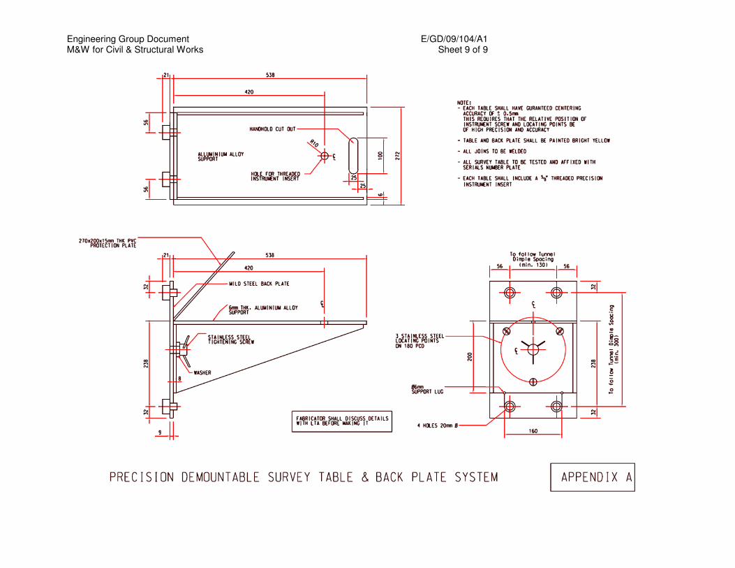
Engineering Group Document E/GD/09/104/A1 M&W for Civil & Structural Works Sheet 9 of 9

Engineering Group Document E/GD/09/104/A1 M&W for Civil & Structural Works Sheet 1 of 19
CHAPTER 4
EARTHWORKS
4.1 GENERAL This Specification is applicable to all earthworks up to formation level. For
road and railway works, formation level shall be the level on which the railway sub-ballast or road sub-base is laid.
Subgrade preparation for road works shall also be subject to the
requirements of Chapter 10 Roadworks. 4.2 CLASSIFICATION OF EARTHWORK MATERIAL The following definitions of earthworks shall apply to this and other clauses
of the Specification in which reference is made to the definitions: -
(a) ‘Top Soil' shall mean the top layer of soil that can support vegetation.
(b) ‘Suitable Material' shall comprise all that is acceptable in accordance with the Contract for use in the works and which is capable of being compacted in the manner specified in Clause 4.12 to form a stable fill having side slopes as indicated on the Drawings.
(c) ‘Not Suitable Material' shall mean other than suitable material and shall include :-
(i) material from swamps, marshes or bogs; (ii) peat, logs, stumps or other organic matter and perishable and toxic
materials; (iii) material susceptible to spontaneous combustion. (iv) clay of liquid limit exceeding 80 and/or plasticity index exceeding
55.
(d) ‘Rock' shall mean hard material found in ledges or masses in its original position, which would normally have to be loosened either by blasting or by pneumatic tools, or if excavated by hand, by wedges and sledge hammers. ‘Rock’ shall also include all solid boulders or detached pieces of rock exceeding 0.10 m
3 in size in trenches or exceeding 0.20 m
3 in
general excavation
(e) ‘Imported Rock Fill' shall be clean well-graded quarry waste provided by the Contractor from sources outside the Site. It shall be resistant to weathering, to the acceptance of the Engineer. The maximum size particles in the material shall pass through a rigid 200mm square grid and the largest dimension of any particle shall not exceed 300 mm. The material shall not have more than 10% of its particles passing a 0.75mm BS sieve.
(f) ‘Fill Material' shall mean Suitable Material for backfilling with the exception of Rock and Imported Rock Fill
Engineering Group Document E/GD/09/104/A1 M&W for Civil & Structural Works Sheet 2 of 19
(g) ‘Special Fill Material’ shall mean Suitable Material of which at least 95 per cent shall pass a 125mm BS sieve and at least 90 per cent shall pass the 75mm BS sieve. Up to 5 per cent of the material may be made up from isolated boulders of maximum dimensions not exceeding half the thickness of the layer of material being placed, provided that the fill can be compacted in the manner specified in Clause 4.12.
The coefficient of uniformity shall be greater than 10. The fraction
passing a 75 µm BS sieve shall be less than 20% by weight and shall have the following characteristics:
(i) liquid limit not exceeding 35 (ii) plasticity index not exceeding 12
(h) ‘Selected Fill' shall be well graded granular natural sands, gravel,
crushed rock, crushed concrete, well burnt shale or other materials accepted by the Engineer. The material passing a 425 micron BS sieve, when tested in accordance with BS 1377, shall have a plasticity index of less than 6%.
(i) ‘Imported Fill Material' shall be Fill Material supplied by the Contractor from a source outside the Site and accepted by the Engineer.
For the purpose of Table 4.1 of Clause 4.12, materials are grouped as follows:- (a) ‘Cohesive Soil' includes clays and marls with up to 20 percent of gravel
and having a moisture content not less than the value of the plastic limit (determined in accordance with BS 1377) minus 4.
(b) ‘Well-Graded Granular and Dry Cohesive Soils' include clays and marls containing more than 20 per cent of gravel and/or having a moisture content less than the value of the plastic limit (determined in accordance with BS 1377) minus 4, and well-graded sands and gravel with a uniformity coefficient exceeding 10.
(c) ‘Uniformly-Graded Material' includes sands and gravel with an uniformity
coefficient of 10 or less, and all silts and pulverised fuel ashes. Any soil containing 80 per cent or more material in the particle size range 0.06 - 0.002mm will be regarded as silt for this purpose.
Naturally occurring materials within the Site that are Not Suitable due only to excessive moisture content may be spread and dried. The use of material treated in this way shall be subject to the acceptance of the Engineer.
4.3 EARTHWORK GENERAL
The Contractor shall carry out all earthwork in such a manner as to prevent erosion or slips and shall limit working faces to safe slopes and height. The Contractor shall ensure that all surfaces have at all times sufficient gradients to enable them to shed water without causing erosion.
Engineering Group Document E/GD/09/104/A1 M&W for Civil & Structural Works Sheet 3 of 19
Hauling of material from cuttings or the importation of fill material to the
embankments or other areas of fill shall proceed only when sufficient compaction plant is operating at the place of deposition to ensure compliance with the requirements of Clause 4.12.
Construction traffic other than that required for the excavation and trimming
shall not use the surface of the bottom of a cutting unless the cutting is in Rock or the Contractor maintains the level of the bottom surface at least 300 mm above formation level. Any damage to the sub-grade arising from such use of the surface shall be made good by the Contractor at his own expense with material having the same characteristics as the material which has been damaged.
The Contractor shall arrange for the rapid dispersal of water shed on to
the earthworks or completed formation during construction, or which enters the earthworks from any source. Where practicable, the water shall be discharged into the permanent outfall for the pipe drainage system. Adequate means for trapping silt shall be provided on temporary systems discharging into permanent drainage systems. The arrangements shall be made in respect of all earthworks including excavations whether for pipe trenches, foundations or cuttings.
The Contractor shall provide where necessary temporary water courses,
ditches, drains, pumping or other means of maintaining the earthworks free from water. Such provision shall include carrying out the work of forming the cuttings and embankments in such a manner that their surfaces have at all times a sufficient minimum crossfall and, where practicable, a sufficient longitudinal gradient to enable them to shed water and prevent ponding.
Pumping shall not be regarded as meeting provisions of this Clause where
a dumpling temporarily obstructs the free drainage of a cutting. In such circumstances the Contractor shall construct temporary drains to a suitable outfall or install the permanent drainage through the dumplings.
The Contractor shall take special care that naturally occurring materials
within the site are not rendered unsuitable by his method of working. Areas of cuttings and excavation shall be so worked that rainfall is conducted rapidly away from the exposed material and at times of expected heavy rain that the cutting areas are protected by appropriate methods of working and drainage provisions. If any material that was suitable in its original position is rendered unsuitable by the Contractor's method of working an equivalent volume of imported Suitable Material shall be provided by the Contractor at his own expense.
If the Contractor allows exposed material, which would provide a suitable
surface for placement of fill when exposed, to reach a condition where compaction of backfilling is impracticable, he shall make good at his own expense either by additional excavation and filling in the manner specified
Engineering Group Document E/GD/09/104/A1 M&W for Civil & Structural Works Sheet 4 of 19
in this clause, or by waiting until the condition of the exposed material is fit to receive the approved backfill.
All Top Soil (including turf) shall be removed from the areas of cuttings and
embankments. Top Soil shall also be removed from existing embankments required to receive paving or additional fill and from areas of new ditches and watercourses. All removed Top Soil shall, where practical, be stockpiled for re-use to soil slopes of cuttings, embankments, berms, verges, reserves and for the provision of beds for the cultivation of trees and shrubs.
The Contractor shall make his own arrangements for stockpiling of Top Soil
and/or Suitable Material, and for the provision of appropriate areas for the purpose.
All excavated Suitable Material together with the surplus from the trenches
and foundation pits after backfilling shall, where possible, be incorporated in the Works and the Contractor shall programme his work to ensure that all possible material can be utilised. No excavated Suitable Material which could subsequently be utilised in the works shall be removed from the Site except on the direction or with the permission of the Engineer. Should the Contractor be permitted to remove Suitable Material from the Site to suit his operational procedure, then he shall make good at his own expense any consequent deficit of filling arising therefrom.
Surplus excavated materials arising from excavation and not required for
filling shall become the responsibility of the Contractor who shall remove such surplus away from the site.
Where the excavation reveals a combination of Suitable and Not Suitable
Materials the Contractor shall, unless otherwise agreed by the Engineer, carry out the excavation in such a manner that the Suitable Materials are excavated separately for use in the Works without contamination by the Not Suitable Materials.
The use of Top Soil shall be restricted to surface layers in positions not
subjected to loading by track, pavements or structures. 4.4 EXCAVATION GENERAL Excavation shall be carried out to the dimensions, lines, levels and slopes
as indicated on the Drawings. If the Contractor excavates deeper than the depths shown on the Drawings or as instructed by the Engineer, then he shall fill in such excessive depths with acceptable materials to the satisfaction of the Engineer.
The bottom of all excavations shall be free from mud and water, trimmed clean, protected from the effects of weather and thoroughly compacted and consolidated by approved manners and means.
Engineering Group Document E/GD/09/104/A1 M&W for Civil & Structural Works Sheet 5 of 19
The Contractor shall be responsible to excavate the top 1m of soft or defective soil below the formation level and backfill with Suitable Material. Such backfill shall be well compacted in layers of accepted thickness.
Brick and concrete foundations to building structures removed during excavation may be incorporated in fill areas, subject to the acceptance of the Engineer. All such material together with any brick or concrete site clearance material permitted by the Engineer shall be regarded as rock fill to which the requirements of Clause 4.2 and Clause 4.12 apply.
4.5 CUTTINGS AND CUT SLOPES 4.5.1 General
Unless otherwise specified, no portion of the earth cutting shall vary from the specified or ordered formation level by an amount exceeding 150mm. In the case of cut slopes, no portion of the completed slope shall vary by an amount exceeding 100mm (measured at right angles to the slope).
In all cuttings, whether in earth or rock, undulations in the general plane of the slope will not be permitted.
Unless otherwise specified, excavation in rock shall extend to at least 150mm below the specified formation level and backfilled with approved materials.
Any overhanging, loose or unstable material, shall be removed.
The excavation shall be so arranged that the working areas are adequately drained throughout the period of construction.
In cutting where the strata consists of earth overlaying rock which is required to be cut to a slope of 1 (H) : 2 (V) or steeper, the face of the rock shall be given its appropriate slope up to the junction of the rock and earth and the latter shall be stripped to form a bench 900mm wide and sloped to the gradient as specified.
4.5.2 Shotcrete To Exposed Slopes
Shotcrete shall be applied to form a skin protection on slopes where specified on the drawing to prevent erosion and weathering.
The minimum thickness and characteristic strength of the shotcrete shall
be 50 mm and 10MPa respectively. The shotcrete should be applied on an exposed slope face as soon as possible, but no later than 24 hours after cutting.
Engineering Group Document E/GD/09/104/A1 M&W for Civil & Structural Works Sheet 6 of 19
The design mix of the shotcrete shall be such that it is pumpable and the
end product will adhere to the slope surface. The water cement ratio shall be 0.4 to 0.5 and the minimum cement content shall be 400kg/m
3.
Suitable admixtures may also be added. In order to provide for drainage of the slope surface, weepholes shall be
provided through the shotcrete and 200mm into the soil or rock at 3m intervals in both horizontal and vertical directions.
4.6 REMOVAL OF ROCKS AND OTHER BLASTING Should rock be met in the course of excavation, it shall be removed by
approved means. The written consent of the Engineer shall be obtained on each occasion the
Contractor wishes to use explosives. If explosives are to be used, the Contractor shall obtain all necessary licences from the appropriate authorities and shall conform to all Government regulations relating to transport, storage, handling and use of the explosives and shall also conform to the rules set out by the Officer-in-Charge of Arms and Explosives.
The Engineer shall be fully informed by the Contractor as to the steps and
precautionary measures taken to safeguard the surrounding properties. The Contractor shall be liable for any accident, damage or injury to any person property or thing, resulting from the use of explosives. When blasting is proposed to be carried out, the Contractor shall determine the danger zone likely to be created and ensure that no damage is caused to persons or property on or off site. Prior to commencing blasting operations a written report listing any existing defects in the structures in the zone which may be affected, supported by photographs where necessary, shall be submitted to the Engineer by the Contractor.
When blasting operations are being carried out, any road affected shall be
closed to traffic and the appropriate signs shall be erected in accordance with the latest “Code of Practice for Temporary Traffic Control” published by the Land Transport Authority.
The Contractor shall comply with the requirements of BS 6657 in respect of
the use of electrical detonators in the vicinity of static and mobile radio transmitters including normal radio and television broadcasting stations and radar units associated with aircraft movements.
Engineering Group Document E/GD/09/104/A1 M&W for Civil & Structural Works Sheet 7 of 19
4.7 EXCAVATION OF PITS AND TRENCHES Where required by the nature of the materials to be excavated, the
Contractor shall provide all necessary planking, strutting and shoring required to uphold the face of the excavation and any necessary stagings. The Contractor shall be responsible for the design, supply, fixing and removal of all planking and strutting required. The planking and strutting shall be of sufficient strength to resist all anticipated loadings, to ensure the safety of the workmen and to prevent damage to any adjoining property.
Alternatively, subject to the prior acceptance of the Engineer, the face of
the excavation may be suitably battered. The bottom of all excavations shall be to the correct levels as shown on
the Drawings. Any over-excavation of foundation pits or trenches below the specified levels shall be filled with grade 15 concrete to the specified levels. Any pocket of soft material or loose rock in the bottoms of pits and trenches shall be removed and the resulting cavities and any large fissures filled with Grade 15 concrete or otherwise with Suitable Material. After the placing of any such concrete, no trimming of the side faces shall be carried out for 24 hours.
No greater length of trench shall be excavated at any one time unless
accepted by the Engineer. All surplus spoil shall be removed immediately on excavation and stacked spoil for filling shall be kept tidy at all times.
All excavated materials from such excavations not required for refilling
shall be disposed of in accordance with the requirements of the Contract. 4.8 BACKFILLING OF PITS AND TRENCHES Unless otherwise shown on the Drawings, all filling for this purpose shall
consist of Suitable Material as defined in Clause 4.2, deposited and compacted by approved plant in accordance with Clause 4.12. Timber sheeting and other excavation supports shall be carefully removed as the filling proceeds except where they are required by the Contract to be left in position. The removal of such supports will not relieve the Contractor of his responsibilities for the stability of the Works.
4.9 FILLING GENERAL Filling works shall include the preparation and compaction as specified
under Clause 4.12. All filling material, whether placed and/or compacted or awaiting placing
and/or compaction which, in the opinion of the Engineer does not comply with this Specification or has been damaged by weather or in any other way, shall be removed and replaced at the Contractor’s expense.
Engineering Group Document E/GD/09/104/A1 M&W for Civil & Structural Works Sheet 8 of 19
When the state of the weather is such that, in the opinion of the Engineer,
it would adversely affect the placing of specially compacted fill, all such work shall be stopped.
End tipping of fill shall not be permitted except in special circumstances
and then only with the acceptance of the Engineer. The end-tipped material shall be compacted to the requirements as specified in Clause 4.12.
4.10 FOUNDATION FOR FILLS Unless otherwise specified, the natural ground over which filling is to be
placed shall be cleared of all loose boulders, grass, topsoil, bushes, trees, roots and other vegetation. Material shall be removed to such depths and over such areas as are acceptable to the Engineer, and shall be disposed of in a manner depending on its nature and condition at the time. The resultant excavation shall be backfilled with Suitable Material as defined in Clause 4.2, deposited and compacted as specified in Clause 4.12.
Before the placing of fill commences any overhanging rock ledges or
caves within the area to be filled shall be removed. The construction of any section of a fill shall not commence until the
formation for that section has been accepted by the Engineer. Where shown on the Drawings, Imported Rock Fill shall be placed directly
on naturally occurring Not Suitable Material. The Rock Fill material shall be deposited and compacted so as to comply with the requirements of Clause 4.12 for the compaction of Rock.
In circumstances where backfill has to be deposited below standing water
the Contractor shall use only Imported Rock Fill as defined in Clause 4.2. Such material may be deposited below water without the associated use of compaction plant.
4.11 EMBANKMENTS AND FILL SLOPES Embankments and other areas of fill shall be formed of Suitable Material as
defined in Clause 4.2, taken to include imported Fill Material, Rock and Imported Rock Fill. Additionally, when permitted by the Engineer, material including imported material, which is wetter than the appropriate limit may be incorporated after drying, in accordance with Clause 4.2.
All earthworks material placed in or below embankments, below formation
level in cuttings or elsewhere in the Works shall be deposited and compacted as soon as practicable after excavation in layers of thickness appropriate to the compaction plant used as permitted in Table 4.1 of Clause 4.12. Except where staging arrangements render it impracticable,

Engineering Group Document E/GD/09/104/A1 M&W for Civil & Structural Works Sheet 9 of 19
embankments shall be built up evenly over the full width and shall be maintained at all times with a sufficient camber and a surface sufficiently even to enable surface water to drain readily from them. During the construction of embankments the Contractor shall control and direct construction traffic uniformly over their full width. Damage to compacted layers by construction traffic shall be made good by the Contractor at his own expense.
Compaction of embankments and other areas of fill shall be undertaken to
the requirements of Clause 4.12. If the material deposited as fill subsequently reaches a condition such that it
cannot be compacted in accordance with the requirements of the Contract, the Contractor shall as directed or accepted by the Engineer either:-
(a) make good by removing the material off the embankment and replacing
it with Suitable Material; or (b) make good the material by mechanical or chemical means to improve
its stability, or (c) cease work on the material until its physical condition is again such that
it can be compacted as required. Rock used in rock fill embankments shall, except for any specified external
cover to slopes or within 500mm of formation levels, be of such size that it can be deposited in horizontal layers each not exceeding 450mm loose depth and extending over the full available width of the embankment. Material shall be spread and levelled by a crawler tractor weighing not less than 15 tonnes and compacted in accordance with Clause 4.12. Each layer shall consist of well-graded rock and all surface voids shall be filled with fine graded materials before the next layer is placed. The top surface and side slopes of embankments so formed shall be thoroughly blinded with approved fine graded material to seal the surface. Such material may on side slopes and verges be Top Soil as defined in Clause 4.2.
Isolated boulders each within the range 0.02m
3 to 0.10m
3 in size may be
incorporated in earth embankments provided that the specified compaction requirements are met and no stone exceeding 0.02m
3 shall be placed less
than 0.5m below the top of the embankment fill. In constructing embankments up to and over culverts, pipe drains and bridges, the Contractor shall bring the embankments up equally on both sides. The requirements of Clause 4.13 shall also be applicable. Filling may proceed over widths less than the full width of the embankment and in steps not exceeding the depth of one layer above the adjoining area of fill. If the Contractor wishes to use the surface of embankments for construction traffic before trimming to formation level, he shall bring up and maintain the area to a level not less than 150mm above formation level, whereupon construction traffic will be allowed to use the surface so formed, but any
Engineering Group Document E/GD/09/104/A1 M&W for Civil & Structural Works Sheet 10 of 19
damage to the subgrade caused by the use of such surface shall be made good by the Contractor at his own expense. In areas of shallow filling where after any removal of Top Soil the ground level is within 300mm of formation level, construction traffic shall not use the surface unless the Contractor brings up and maintains the surface level at least 300mm above formation level. Any damage to the subgrade arising from such use shall be made good by the Contractor at his own expense with material having the same characteristics as the damaged material. The slope faces of embankments or other fill areas shall be formed by overfilling, cutting back and trimming neatly to the determined profile. The designed embankment slopes shall be reviewed by the Contractor to take account of the actual nature of the fill material, and shall be adjusted to if necessary to the acceptance of the Engineer.
When completed, the average planes of the slopes of embankments shall conform to those shown on the Drawings or otherwise determined. No point on the completed slope shall vary from the required slope by an amount exceeding 150mm measured at right angles to the slope. Undulations in the general plane of the slope shall not be permitted.
4.12 COMPACTION OF FILL 4.12.1 General
All materials shall be compacted in layers as soon as practicable after deposition. Before commencing any filling, each class of material to be compacted shall be tested by an acceptable laboratory to establish the maximum value of the dry density that can be obtained and the optimum moisture content for compaction. Testing shall be in accordance with BS 1377. Table 4.1 of Clause 4.12.2 may be used as a guide in establishing appropriate in-situ compaction methods. The depth of each compacted layer shall be compatible with the compaction plant used and shall not be greater than the maximum depth of compacted layer specified for each type of compaction plant. Earthmoving plant will not be accepted as compaction equipment. Variations from the methods given in this table, or the use of plant not included therein, will be permitted only if the Contractor demonstrates to the satisfaction of the Engineer at site trials that the required field density will be achieved. The method of compaction being used must produce a compacted fill material having a field density of at least the following percentage of the maximum dry density previously established for that material:

Engineering Group Document E/GD/09/104/A1 M&W for Civil & Structural Works Sheet 11 of 19
(a) 95% in the case of material within 500mm of formation level (b) 90% in the case of material more than 500mm below formation level
Notwithstanding compliance with Table 4.1, the Contractor must verify by site tests that the required field density is being achieved and make any adjustments to his compaction methods, which may be necessary. Field density shall be determined by in-situ tests in accordance with BS 1377. Each layer of fill shall be tested and accepted by the Engineer prior to the placing of the next layer. At least 3 in-situ field density tests shall be carried out for every 300m
2 or less of surface area of each
compacted layer. In-situ field density tests shall be carried out by Sand Replacement Method or Water Displacement Method in accordance with BS 1377. The moisture content of the in-situ material during compaction shall be maintained as close to the optimum moisture content as possible. If necessary, this shall be adjusted by wetting or drying on site to enable the required in-situ field densities of the fill material to be obtained consistently. When materials of widely divergent characteristics are used in embankments and fill areas they shall be spread and compacted in separate clearly defined areas in such a manner as to comply with the requirements of this clause. If more than one class of material is being used in such a way that is not practicable to define the areas in which each class occurs, compaction plant shall be operated as if only the material which requires the greatest compaction effort is being compacted. The following requirements are applicable to Rock used as fill material. Each layer of Rock used as rock fill in embankments shall be spread and levelled in accordance with Clause 4.11 and systematically compacted by at least 12 passes of a towed vibratory roller with a static load per metre width of roll of at least 1800kg or a grid roller with a load per metre width of roll of at least 8000kg or other approved plant. Where, however, the rock contains sufficient soft material for satisfactory compaction to the requirements of Table 4.1 for well graded granular soil, the fill shall be compacted to the latter requirements. In order that the Engineer may make proper provision for the supervision of compaction in the permanent work, the Contractor shall, not less than 24 hours before he proposes to carry out compaction processes during periods of overtime, apply in writing to the Engineer for permission to do so.
Engineering Group Document E/GD/09/104/A1 M&W for Civil & Structural Works Sheet 12 of 19
4.12.2 Compaction by Mechanical Plant
Table 4.1 gives requirements for compaction of soil by mechanical plant. This table is to be read in accordance with the following definitions:
(a) The depth of compacted layer is the height by which an
embankment is raised by each successive compacted layers. (b) The number of passes is the number of times that each point on
the surface of the layer being compacted has been traversed by the compaction plant (or struck in the case of power rammers or dropping weight compactors).
The effective width of a pneumatic-tyred roller, for this purpose, is the sum of the widths of the individual wheel tracks together with the sum of the spacing between the wheel tracks provided that each spacing does not exceed 230mm. Where the spacing exceeds 230mm the effective width shall be taken as the sum of the widths of the individual wheel tracks only.
(c) The force per 100mm width of roll is the total weight on the roller
divided by the total roll width. Where a smooth-wheeled roller has more than one axle the machine shall be assessed on the basis of the axle giving the highest value of force per 100mm width. Wheel load is the total weight of the roller divided by number of wheels.
(d) Tamping rollers are machines with a roll or rolls from which 'feet'
project. The projected end area of each 'foot' shall exceed 0.01m2
and the sum of the areas of the feet shall exceed 15 per cent of the area of the cylinder swept by the ends of the feet. The requirements for tamping rollers apply to machines that have 2 rolls in tandem. If only one tamping roll traverses each point on the surface of the layer on any one pass of the machine, the minimum number of passes shall be twice the number given in Table 4.1.
(e) Vibratory rollers are self propelled or towed rollers having means of applying mechanical vibration to one or more rolls.
The requirements for vibratory rollers are based on the use of the lowest gear on a self propelled machine and a towing speed of 1800 - 2400m/hr for a towed machine. If higher gears or speeds are used, an increased number of passes shall be provided in proportion to the increase in speed of travel.
Where the mechanical vibration is applied to two rolls in tandem, the
minimum number of passes shall be half the number given in Table 4.1 for the appropriate mass per metre width of one vibrating roll. If one roll differs in mass per metre width from the other the number of passes shall be calculated as for the roll with the smallest value. Alternatively the machine may be treated as having a single vibrating
Engineering Group Document E/GD/09/104/A1 M&W for Civil & Structural Works Sheet 13 of 19
roll with a mass per metre width equal to that of the roll with the higher value.
Vibratory type rollers operating without vibration will be classified as
smooth wheeled rollers. Vibratory rollers shall only be operated with their vibration
mechanism operating at the frequency of vibration recommended by the manufacturers. All such rollers shall be equipped with a device automatically indicating the frequency at which the mechanism is operating.
(f) Vibrating-plate compactors are machines having a base plate to
which is attached a source of vibration consisting of one or two eccentrically weighted shafts.
The static pressure under the plate of a vibrating-plate compactor is calculated by dividing the total weight of the machine in working order by the area in contact with compacted material. Vibrating-plate compactors shall be operated at the frequency of vibration recommended by the manufacturer. They shall normally be operated at travelling speeds of less than 900m/hr but, if higher speeds are necessary, the number of passes shall be increased in proportion to the increase in speed of travel.
(g) Vibro-tampers are machines in which an engine-driven
reciprocating mechanism acts on a spring system, through which oscillations are set up in a base plate.
(h) Power rammers are machines which are actuated by explosions in
an internal combustion cylinder, each explosion being controlled manually by the operator.
In the case of power rammers and dropping weight compactors one
pass will be considered as made when the compacting, shoe has made contiguous strikes on the whole of the area to be compacted.
(i) For items marked with an asterisk (*), the rollers shall be towed by
track-laying tractors. Self-propelled rollers are unsuitable. (j) Where combination of different types of categories of plant are
used, the compaction requirements shall be: - The depth of layer shall be that for the type of plant requiring
the least depth of layer. - The number of passes shall be that for the type of plant
requiring the greatest number of passes.
Engineering Group Document E/GD/09/104/A1 M&W for Civil & Structural Works Sheet 14 of 19
However, where the Contractor uses a lighter type of plant to
provide some preliminary compaction only to assist the use of heavier plant, this shall be disregarded in assessing the above requirements.
4.13 FILL ADJACENT TO BRIDGE ABUTMENTS, CULVERTS, RETAINING
WALLS AND UNDERGROUND STRUCTURES Where structures against which backfill is to be placed have weepholes, a
filter drain layer shall be provided. The filter drain shall consist of clean, hard and durable broken stones or hardcore conforming to the grading specified in Table 4.2. The larger stones shall be placed adjacent to the weepholes and the smaller particles behind and above the larger particles.
The filter drain shall extend horizontally across the whole width of the
structures. Unless otherwise stated, it shall have a width of 300mm and shall vertically cover every weephole by at least 300mm.
Where a waterproofing membrane system is being applied progressively
up an external wall of an underground structure, backfill shall not progress above a level 500mm below the top of the membrane at any stage, until the next section of the membrane above has been applied and bonded to the stage in question.
Within the limits defined in Table 4.3, adjacent to all structures, Special Fill
Material as defined in Clause 4.2 shall be provided. Fill shall be placed in horizontal layers of thickness appropriate to the compacting plant used and shall be compacted with care to the density specified in Clause 4.12 for fill material.

Engineering Group Document E/GD/09/104/A1 M&W for Civil & Structural Works Sheet 15 of 19
TABLE 4.1 COMPACTION REQUIREMENTS Type of
Compaction Plant
Category
Cohesive Soil
Well-graded granular and dry cohesive soils
Uniformly -graded materials
Max depth of
Compacted layer (mm)
Min No. of
passes
Max depth of
Compacted layer (mm)
Min No. of
passes
Max depth of
Compacted layer (mm)
Min No. of passes
Smooth-wheeled
roller
Force per 100 mm width
2.1 - 2.6 kN 2.61 - 5.2 kN
125 125
8 6
125 125
10 8
125 125
10* 8*
More than 5.2 kN
150 4 150 8 Unsuitable
Gridroller Force per 100mm width
2.6 - 5.2 kN 150 10 Unsuitable 150 10 5.3 - 7.8 kN
More than 7.8kN
150 150
8 4
125 150
12 12
Unsuitable Unsuitable
Tamping roller
More than 40 kN
225 4 150 12 250 4
Pneumatic- tyred roller
Wheel Load
1 - 1.5 tonnes 125 6 Unsuitable 150 10* 1.5 - 2 tonnes 150 5 Unsuitable Unsuitable 2 - 2.5 tonnes
2.5 – 4 tonnes 4 - 6 tonnes 6 - 8 tonnes 8 - 12 tonnes
More than 12 tonnes
175 225 300 350 400
450
6 5 4 4 4 4
125 125 125 150 150
175
12 10 10 8 8
6
Unsuitable Unsuitable Unsuitable Unsuitable Unsuitable
Unsuitable
Vibratory roller
Force per 100 mm width
0.25 - 0.45kN 0.46- 0.70 kN
Unsuitable Unsuitable
75 75
16 12
150 150
16 12
0.71 -1.25 kN 1.26- 1.75 kN 1.76- 2.30 kN 2.31- 2.80 kN 2.81- 3.50 kN 3.51- 4.20 kN 4.21- 4.90 kN
100 125 150 175 200 225 250
12 8 4 4 4 4 4
125 150 150 175 200 225 250
12 8 4 4 4 4 4
150 200 225 250 275 300 300
6 10* 12* 10* 8* 8* 8*
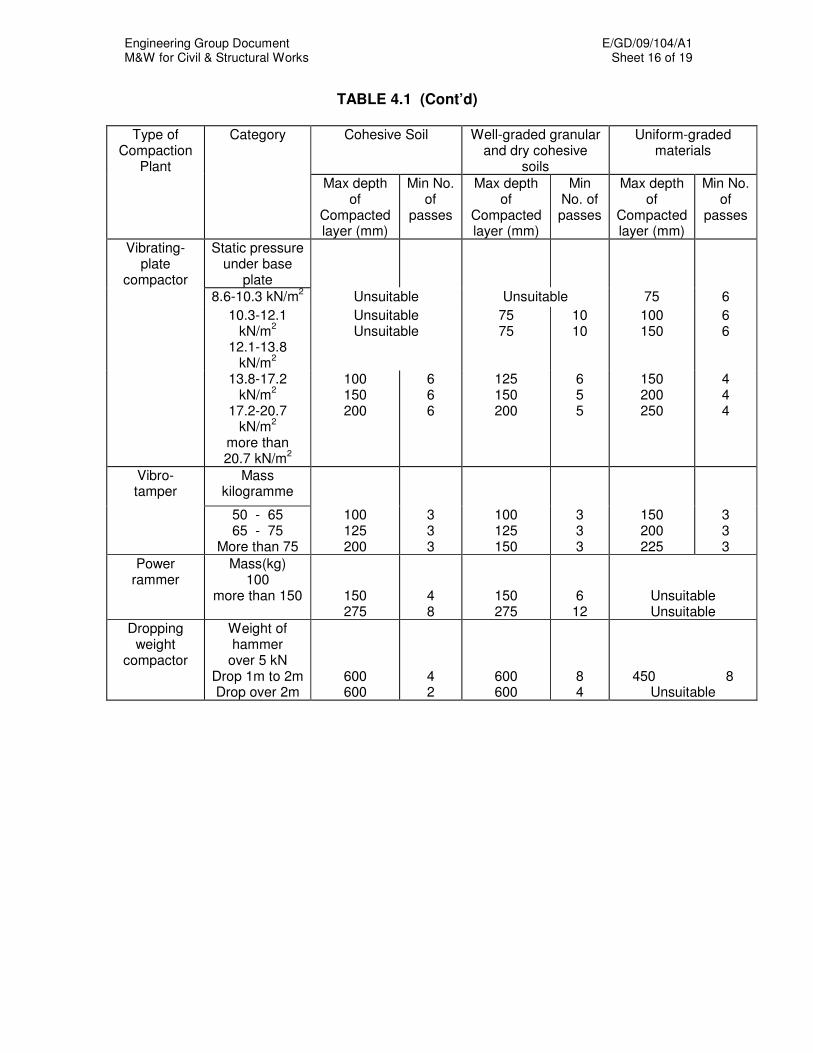
Engineering Group Document E/GD/09/104/A1 M&W for Civil & Structural Works Sheet 16 of 19
TABLE 4.1 (Cont’d)
Type of Compaction
Plant
Category Cohesive Soil Well-graded granular and dry cohesive
soils
Uniform-graded materials
Max depth of
Compacted layer (mm)
Min No. of
passes
Max depth of
Compacted layer (mm)
Min No. of passes
Max depth of
Compacted layer (mm)
Min No. of
passes
Vibrating-plate
compactor
Static pressure under base
plate
8.6-10.3 kN/m2 Unsuitable Unsuitable 75 6
10.3-12.1 kN/m
2
12.1-13.8 kN/m
2
Unsuitable Unsuitable
75 75
10 10
100 150
6 6
13.8-17.2 kN/m
2
17.2-20.7 kN/m
2
more than 20.7 kN/m
2
100 150 200
6 6 6
125 150 200
6 5 5
150 200 250
4 4 4
Vibro- tamper
Mass kilogramme
50 - 65 65 - 75
More than 75
100 125 200
3 3 3
100 125 150
3 3 3
150 200 225
3 3 3
Power rammer
Mass(kg) 100
more than 150
150 275
4 8
150 275
6 12
Unsuitable Unsuitable
Dropping weight
compactor
Weight of hammer
over 5 kN Drop 1m to 2m Drop over 2m
600 600
4 2
600 600
8 4
450 8 Unsuitable
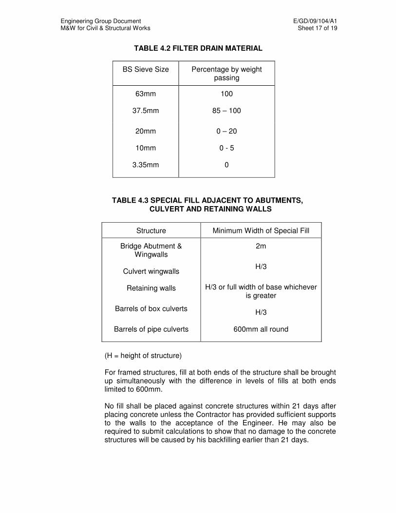
Engineering Group Document E/GD/09/104/A1 M&W for Civil & Structural Works Sheet 17 of 19
TABLE 4.2 FILTER DRAIN MATERIAL
BS Sieve Size Percentage by weight passing
63mm
37.5mm
100
85 – 100
20mm
10mm
3.35mm
0 – 20
0 - 5
0
TABLE 4.3 SPECIAL FILL ADJACENT TO ABUTMENTS, CULVERT AND RETAINING WALLS
Structure Minimum Width of Special Fill
Bridge Abutment & Wingwalls
Culvert wingwalls
Retaining walls
Barrels of box culverts
Barrels of pipe culverts
2m
H/3
H/3 or full width of base whichever is greater
H/3
600mm all round
(H = height of structure)
For framed structures, fill at both ends of the structure shall be brought up simultaneously with the difference in levels of fills at both ends limited to 600mm.
No fill shall be placed against concrete structures within 21 days after placing concrete unless the Contractor has provided sufficient supports to the walls to the acceptance of the Engineer. He may also be required to submit calculations to show that no damage to the concrete structures will be caused by his backfilling earlier than 21 days.
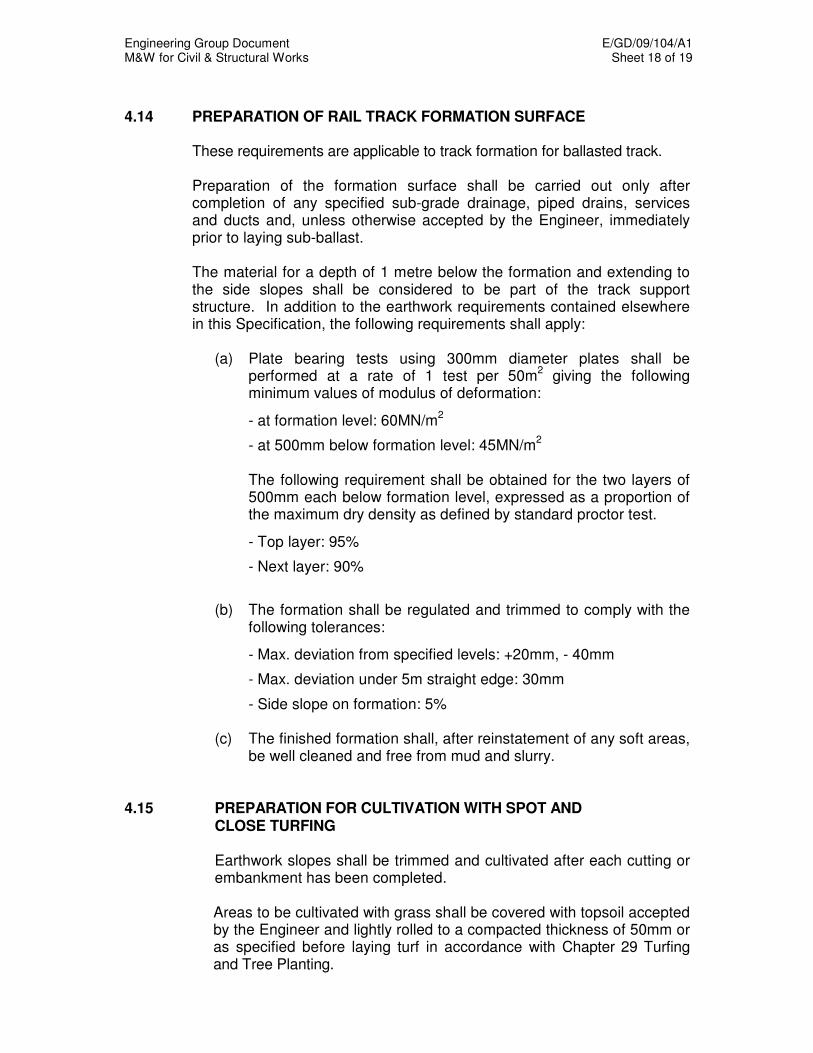
Engineering Group Document E/GD/09/104/A1 M&W for Civil & Structural Works Sheet 18 of 19
4.14 PREPARATION OF RAIL TRACK FORMATION SURFACE
These requirements are applicable to track formation for ballasted track.
Preparation of the formation surface shall be carried out only after completion of any specified sub-grade drainage, piped drains, services and ducts and, unless otherwise accepted by the Engineer, immediately prior to laying sub-ballast.
The material for a depth of 1 metre below the formation and extending to
the side slopes shall be considered to be part of the track support structure. In addition to the earthwork requirements contained elsewhere in this Specification, the following requirements shall apply:
(a) Plate bearing tests using 300mm diameter plates shall be
performed at a rate of 1 test per 50m2 giving the following
minimum values of modulus of deformation: - at formation level: 60MN/m
2
- at 500mm below formation level: 45MN/m
2
The following requirement shall be obtained for the two layers of
500mm each below formation level, expressed as a proportion of the maximum dry density as defined by standard proctor test.
- Top layer: 95% - Next layer: 90%
(b) The formation shall be regulated and trimmed to comply with the following tolerances:
- Max. deviation from specified levels: +20mm, - 40mm - Max. deviation under 5m straight edge: 30mm - Side slope on formation: 5% (c) The finished formation shall, after reinstatement of any soft areas,
be well cleaned and free from mud and slurry. 4.15 PREPARATION FOR CULTIVATION WITH SPOT AND CLOSE TURFING Earthwork slopes shall be trimmed and cultivated after each cutting or
embankment has been completed.
Areas to be cultivated with grass shall be covered with topsoil accepted by the Engineer and lightly rolled to a compacted thickness of 50mm or as specified before laying turf in accordance with Chapter 29 Turfing and Tree Planting.

Engineering Group Document E/GD/09/104/A1 M&W for Civil & Structural Works Sheet 19 of 19
4.16 GEOTEXTILE
Unless otherwise specified, geotextiles shall be non-woven and shall be made of polypropylene, polyethylene, polyester or a combination of the aforesaid materials. Geotextiles shall not be susceptible to bacteria and fungus attack and shall be resistant to chemical action and not affected by exposure to ultra-violet light. Where the geotextiles serve a separation or reinforcement function, class A geotextile shall be used. Where the geotextiles serve a filtration function, class B geotextiles shall be used. The requirements for class A and class B geotextiles shall be as specified in Table 4.4. The Contractor shall submit method of laying and jointing to the Engineer for acceptance prior to commencement of work.
TABLE 4.4 PHYSICAL PROPERTIES OF GEOTEXTILES
Class of Geotextile Physical Property Class A Class B
Specification
Minimum Unit Weight, g/m
2
Minimum Grab Tensile Strength, N Minimum Elongation To Break, % Minimum Trapezoidal Tear Strength, N Water Permeability, cm/sec
125
530
60
180
2.0x10 -2
50
270
55
80
2.7x10 -2
ASTM D5261 or ISO 9864
ASTM D4632
ASTM D4595 Or ISO 10319
ASTM D4533
Manufacturer’s test report to be
submitted.
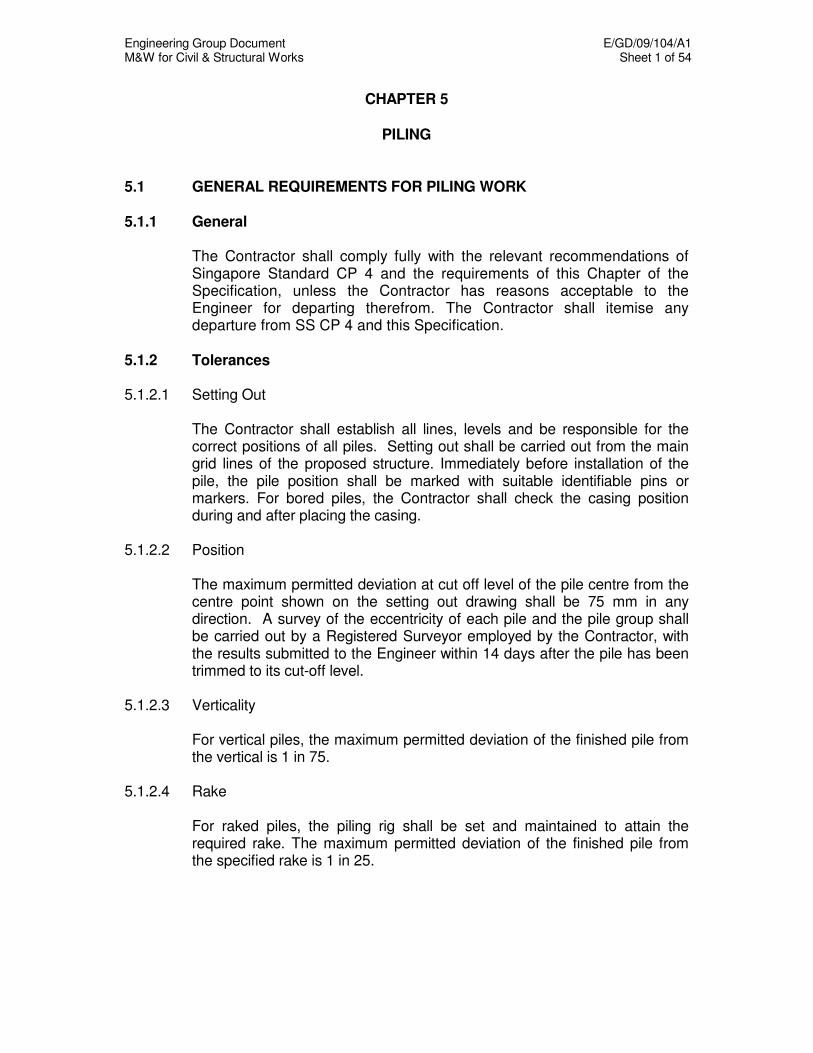
Engineering Group Document E/GD/09/104/A1 M&W for Civil & Structural Works Sheet 1 of 54
CHAPTER 5
PILING
5.1 GENERAL REQUIREMENTS FOR PILING WORK 5.1.1 General The Contractor shall comply fully with the relevant recommendations of
Singapore Standard CP 4 and the requirements of this Chapter of the Specification, unless the Contractor has reasons acceptable to the Engineer for departing therefrom. The Contractor shall itemise any departure from SS CP 4 and this Specification.
5.1.2 Tolerances 5.1.2.1 Setting Out The Contractor shall establish all lines, levels and be responsible for the
correct positions of all piles. Setting out shall be carried out from the main grid lines of the proposed structure. Immediately before installation of the pile, the pile position shall be marked with suitable identifiable pins or markers. For bored piles, the Contractor shall check the casing position during and after placing the casing.
5.1.2.2 Position The maximum permitted deviation at cut off level of the pile centre from the
centre point shown on the setting out drawing shall be 75 mm in any direction. A survey of the eccentricity of each pile and the pile group shall be carried out by a Registered Surveyor employed by the Contractor, with the results submitted to the Engineer within 14 days after the pile has been trimmed to its cut-off level.
5.1.2.3 Verticality For vertical piles, the maximum permitted deviation of the finished pile from
the vertical is 1 in 75. 5.1.2.4 Rake For raked piles, the piling rig shall be set and maintained to attain the
required rake. The maximum permitted deviation of the finished pile from the specified rake is 1 in 25.
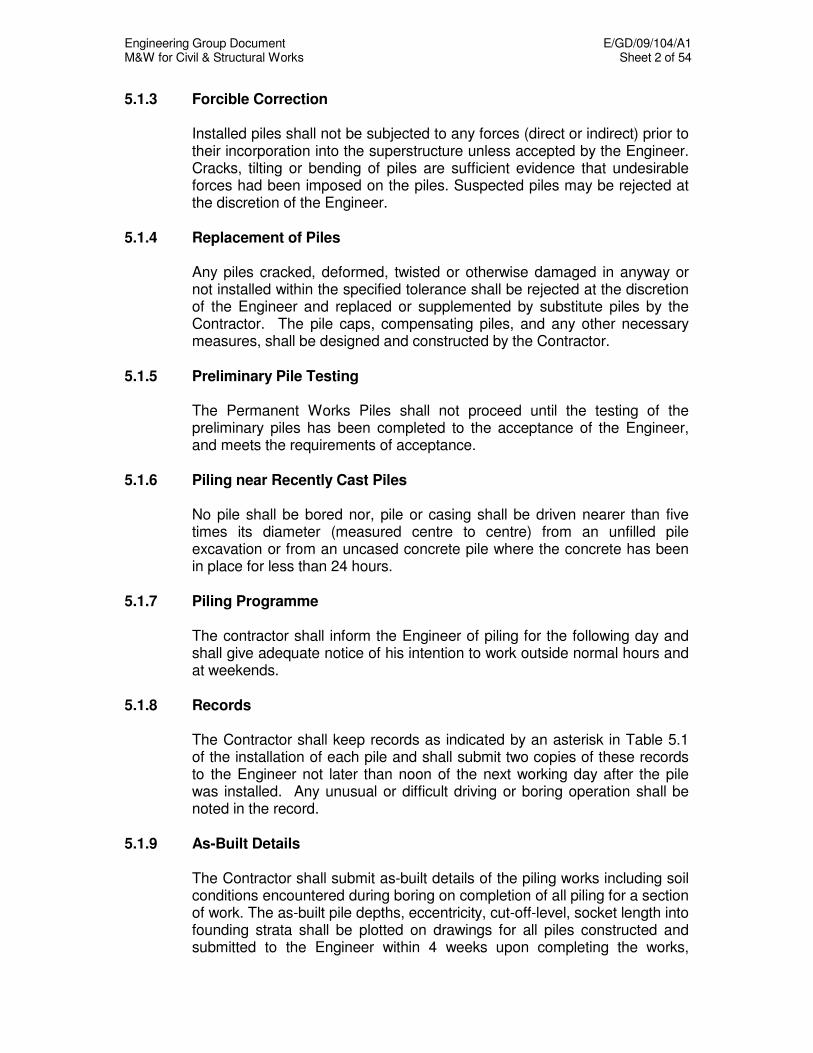
Engineering Group Document E/GD/09/104/A1 M&W for Civil & Structural Works Sheet 2 of 54
5.1.3 Forcible Correction Installed piles shall not be subjected to any forces (direct or indirect) prior to
their incorporation into the superstructure unless accepted by the Engineer. Cracks, tilting or bending of piles are sufficient evidence that undesirable forces had been imposed on the piles. Suspected piles may be rejected at the discretion of the Engineer.
5.1.4 Replacement of Piles Any piles cracked, deformed, twisted or otherwise damaged in anyway or
not installed within the specified tolerance shall be rejected at the discretion of the Engineer and replaced or supplemented by substitute piles by the Contractor. The pile caps, compensating piles, and any other necessary measures, shall be designed and constructed by the Contractor.
5.1.5 Preliminary Pile Testing The Permanent Works Piles shall not proceed until the testing of the
preliminary piles has been completed to the acceptance of the Engineer, and meets the requirements of acceptance.
5.1.6 Piling near Recently Cast Piles No pile shall be bored nor, pile or casing shall be driven nearer than five
times its diameter (measured centre to centre) from an unfilled pile excavation or from an uncased concrete pile where the concrete has been in place for less than 24 hours.
5.1.7 Piling Programme The contractor shall inform the Engineer of piling for the following day and
shall give adequate notice of his intention to work outside normal hours and at weekends.
5.1.8 Records The Contractor shall keep records as indicated by an asterisk in Table 5.1
of the installation of each pile and shall submit two copies of these records to the Engineer not later than noon of the next working day after the pile was installed. Any unusual or difficult driving or boring operation shall be noted in the record.
5.1.9 As-Built Details The Contractor shall submit as-built details of the piling works including soil
conditions encountered during boring on completion of all piling for a section of work. The as-built pile depths, eccentricity, cut-off-level, socket length into founding strata shall be plotted on drawings for all piles constructed and submitted to the Engineer within 4 weeks upon completing the works,
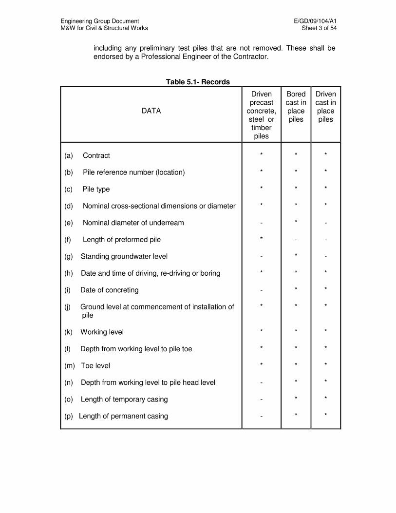
Engineering Group Document E/GD/09/104/A1 M&W for Civil & Structural Works Sheet 3 of 54
including any preliminary test piles that are not removed. These shall be endorsed by a Professional Engineer of the Contractor.
Table 5.1- Records
DATA
Driven precast
concrete, steel or timber piles
Bored cast in place piles
Driven cast in place piles
(a) Contract (b) Pile reference number (location) (c) Pile type (d) Nominal cross-sectional dimensions or diameter (e) Nominal diameter of underream (f) Length of preformed pile (g) Standing groundwater level (h) Date and time of driving, re-driving or boring (i) Date of concreting (j) Ground level at commencement of installation of
pile (k) Working level (l) Depth from working level to pile toe (m) Toe level (n) Depth from working level to pile head level (o) Length of temporary casing (p) Length of permanent casing
* * * * - * - * - * * * * - - -
* * * * * - * * * * * * * * * *
* * * * - - - * * * * * * * * *

Engineering Group Document E/GD/09/104/A1 M&W for Civil & Structural Works Sheet 4 of 54
TABLE 5.1 (Cont’d)
DATA
Driven precast
concrete, steel or timber piles
Bored cast in place piles
Driven cast in place piles
(q) Type, weight, drop and mechanical condition of
hammer and equivalent information for other equipment
(r) Number and type of packing used and type and
condition of dolly used during driving the pile (s) Set of pile in mm per 10 blows (t) If required, the sets taken at intervals during the
last 3m of driving (u) If required, temporary compression of ground and
pile from time of a marked increase in driving resistance until pile reaches its final level
(v) Soil samples taken and insitu tests carried out (w) Length and details of reinforcement (x) Concrete mix (y) Volume of concrete supplied to pile where this
can be measured in practice (z) All information regarding obstructions/delays and
other Interruptions to the sequence of work
* * * * * - - - - *
- - - - - * * * * *
* * * * * * - * * *
5.2 REQUIREMENTS FOR REINFORCED CONCRETE IN PILES 5.2.1 General Unless otherwise specified in this Section, the requirements in Chapter 11
Concrete and Reinforcement shall apply to the construction of all concrete piles. Where sulphates are found in soil or ground water, sulphate resisting cement should be used.
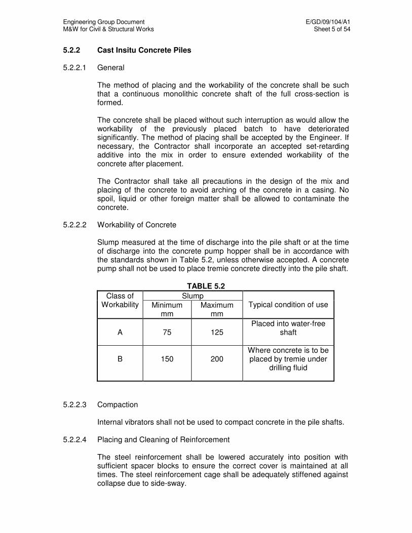
Engineering Group Document E/GD/09/104/A1 M&W for Civil & Structural Works Sheet 5 of 54
5.2.2 Cast Insitu Concrete Piles 5.2.2.1 General The method of placing and the workability of the concrete shall be such
that a continuous monolithic concrete shaft of the full cross-section is formed.
The concrete shall be placed without such interruption as would allow the
workability of the previously placed batch to have deteriorated significantly. The method of placing shall be accepted by the Engineer. If necessary, the Contractor shall incorporate an accepted set-retarding additive into the mix in order to ensure extended workability of the concrete after placement.
The Contractor shall take all precautions in the design of the mix and
placing of the concrete to avoid arching of the concrete in a casing. No spoil, liquid or other foreign matter shall be allowed to contaminate the concrete.
5.2.2.2 Workability of Concrete Slump measured at the time of discharge into the pile shaft or at the time
of discharge into the concrete pump hopper shall be in accordance with the standards shown in Table 5.2, unless otherwise accepted. A concrete pump shall not be used to place tremie concrete directly into the pile shaft.
TABLE 5.2
Slump Class of Workability Minimum
mm Maximum
mm
Typical condition of use
A
75
125
Placed into water-free shaft
B
150
200
Where concrete is to be placed by tremie under
drilling fluid
5.2.2.3 Compaction Internal vibrators shall not be used to compact concrete in the pile shafts. 5.2.2.4 Placing and Cleaning of Reinforcement The steel reinforcement shall be lowered accurately into position with
sufficient spacer blocks to ensure the correct cover is maintained at all times. The steel reinforcement cage shall be adequately stiffened against collapse due to side-sway.
Engineering Group Document E/GD/09/104/A1 M&W for Civil & Structural Works Sheet 6 of 54
5.2.2.5 Placing Concrete in Dry Shafts If the pile shaft is completely dry and stable, the Engineer may at his
discretion, allow concrete to be discharged directly into the borehole. Before placing of concrete, all loose materials must be cleaned out. Accepted measures shall be taken to avoid loosening of the sidewalls of the shaft, concrete segregation and bleeding and to ensure that the concrete at the bottom of the borehole is not deficient in grout.
5.2.2.6 Placing Concrete under Water or under Drilling Fluid Concrete to be placed under water or drilling fluid shall be placed using a
tremie concrete pipe. Alternative methods of underwater placement such as the use of a drop bottom bucket or hose from a concrete pump will not be accepted by the Engineer. At no stage shall concrete be discharged freely into the water or drilling fluid.
Before placing the concrete, the Contractor shall ensure, by a method
acceptable to the Engineer, that there is no accumulation of silt or other material at the base of the boring and the Contractor shall ensure that heavily contaminated bentonite suspension, which could impair the free flow of concrete from the tremie pipe has not accumulated in the bottom of the hole.
A sample of the bentonite suspension shall be taken from the base of the
boring using an accepted sampling device. If the specific gravity of the suspension exceeds 1.25, the placing of concrete shall not proceed. In this event, the Contractor shall modify or replace the bentonite as agreed to meet the Specification.
The hopper and pipe of the tremie shall be clean and watertight
throughout. Before any set of tremie pipes is allowed to be used, a watertightness test shall be carried out. Thereafter, the order of tremie tube connections shall not be changed until the next watertightness test. The Contractor shall carry out the watertightness test at the discretion of the Engineer whenever water is found inside the tremie tubes during concreting. The pipe shall extend to the base of the boring and a sliding plug or barrier shall be placed in the pipe to prevent direct contact between the first charge of concrete in the tremie pipe and the water or drilling fluid. If the plug or barrier is sacrificial, it shall not be retained in the mass of the concrete.
The tremie pipe outlet shall be kept at least 3 metre below the surface of
the concrete at all stages in the pour. The Contractor shall develop a system of level checks for the concrete and pipe outlet to ensure that this requirement is met.
At all times, a sufficient quantity of concrete shall be maintained within the
pipe to ensure that the pressure from it exceeds that from the water or drilling fluid. The internal diameter of the pipe of the tremie shall not be less than 250 mm.
Engineering Group Document E/GD/09/104/A1 M&W for Civil & Structural Works Sheet 7 of 54
Should a delay or breakdown occur during the concreting operation which
in the opinion of the Engineer could cause a cold joint, entrapment of laitance in the tremie concrete, or otherwise lead to defective concrete, concrete placing shall be halted. Before the remainder of the pile shaft can be concreted, the pile shall be dewatered and the top surface of the tremie concrete cut back to sound concrete and cleaned of all laitance and weak concrete. The remainder of the pile shall either be cast by tremie or in the dry, as directed by the Engineer.
5.2.2.7 Trimming of Pile Head The pile shall be cast to a minimum 600mm above the cut-off level so as to
achieve sound concrete upon trimming down to the cut-off level. 5.2.2.8 Monitoring of Concrete Level during Pile Casting For each truckload of concrete discharged, the rise in concrete level shall
be counter-checked against the expected increase. If the rise in concrete level is found to be higher than it is physically possible with the amount of concrete discharged, the Contractor shall demonstrate that the integrity of the pile is to the acceptance of the Engineer.
5.2.3 Precast Reinforced and Prestressed Concrete Piles 5.2.3.1 General Precast concrete piles must be reinforced. The minimum number of
longitudinal bars provided in a precast concrete section should be four in square piles and six in circular and hexagonal piles and their size shall not be less than 12mm in diameter. In any case, the total cross sectional area of these bars shall not be less than 1% of the cross section of the pile.
When the precast concrete section is a square, the corners shall be
chamfered. Where two or more precast sections have to be joined to give the length of
pile required, full details of the method of jointing shall be provided to the Engineer for acceptance. The joint shall be capable of generating the full axial and bending capacity of the pile. The Engineer may require joint testing to be carried out before acceptance is given.
5.2.3.2 Tolerances in Pile Dimensions The cross-sectional dimensions of the pile shall not be less than those
specified and shall not exceed them by more than 6mm. Any face of a pile shall not deviate by more than 6mm from a straight edge 3m long laid on the face, and the centroid of any cross-section of the pile shall not deviate by more than 12mm from the straight line connecting the centroids of the end faces of the piles.
Engineering Group Document E/GD/09/104/A1 M&W for Civil & Structural Works Sheet 8 of 54
5.2.3.3 Reinforcement in Piles The main longitudinal reinforcing bars in piles not exceeding 12 m in length
shall be in one continuous length unless otherwise specified. In piles exceeding 12 m long, joints will be permitted in main longitudinal bars at 12 m nominal intervals. Joints in adjacent bars shall be staggered at least 1 m apart along the length of the pile.
Joints in reinforcement shall be such that the full strength of the bar is
effective across the joint. 5.2.3.4 Formwork for Piles When the sides of adjacent piles are used as formwork, an accepted
method shall be used to prevent adhesion between concrete surfaces. The head of each pile shall be square to the longitudinal axis. The corners
of the head and the corners of the pile shaft for a distance of 300mm from the head shall be chamfered 25mm x 25mm.
The point of the pile or shoe shall lie on the longitudinal axis of the pile. Holes for toggle bolts shall be at right angles to the faces of the pile, and
shall be lined with steel tubes or other accepted material. Holes for handling and pitching shall be provided and shall be lined with steel tubes, alternatively, accepted inserts may be cast in.
5.2.3.5 Casting of Piles The Contractor shall ensure that the Engineer is given adequate notice and
every facility for inspecting the pile manufacturing process. Testing of all material used shall be in accordance with the Contract.
5.2.3.6 Cutting Off Pile Heads On completion of installation of piles, the piles shall be cut off to the
required level as shown on the Drawings and to a tolerance of ±20 mm or otherwise instructed by the Engineer. For precast reinforced concrete piles, the main reinforcement shall be exposed and left reasonably straight for bonding into the pile cap. The minimum bond length of main reinforcement to be exposed shall be as given in Table 5.3.
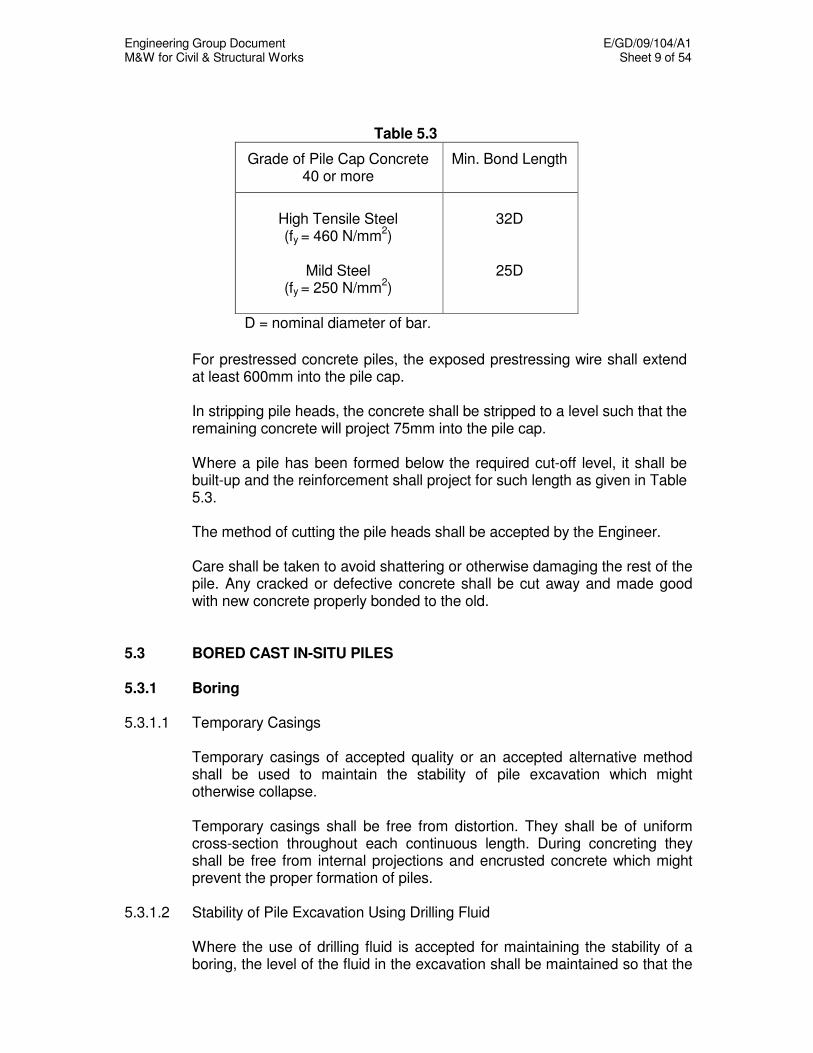
Engineering Group Document E/GD/09/104/A1 M&W for Civil & Structural Works Sheet 9 of 54
Table 5.3
Grade of Pile Cap Concrete 40 or more
Min. Bond Length
High Tensile Steel (fy = 460 N/mm
2)
Mild Steel
(fy = 250 N/mm2)
32D
25D
D = nominal diameter of bar.
For prestressed concrete piles, the exposed prestressing wire shall extend
at least 600mm into the pile cap. In stripping pile heads, the concrete shall be stripped to a level such that the
remaining concrete will project 75mm into the pile cap. Where a pile has been formed below the required cut-off level, it shall be
built-up and the reinforcement shall project for such length as given in Table 5.3.
The method of cutting the pile heads shall be accepted by the Engineer. Care shall be taken to avoid shattering or otherwise damaging the rest of the
pile. Any cracked or defective concrete shall be cut away and made good with new concrete properly bonded to the old.
5.3 BORED CAST IN-SITU PILES 5.3.1 Boring 5.3.1.1 Temporary Casings Temporary casings of accepted quality or an accepted alternative method
shall be used to maintain the stability of pile excavation which might otherwise collapse.
Temporary casings shall be free from distortion. They shall be of uniform
cross-section throughout each continuous length. During concreting they shall be free from internal projections and encrusted concrete which might prevent the proper formation of piles.
5.3.1.2 Stability of Pile Excavation Using Drilling Fluid Where the use of drilling fluid is accepted for maintaining the stability of a
boring, the level of the fluid in the excavation shall be maintained so that the
Engineering Group Document E/GD/09/104/A1 M&W for Civil & Structural Works Sheet 10 of 54
fluid pressure always exceeds the pressures exerted by the soils and external groundwater, and an adequate temporary casing shall be used in conjunction with the method to ensure stability of the strata near ground level until concrete has been placed. The fluid level shall be maintained at a level not less than 1.5 m above the level of the external groundwater.
In the event of a rapid loss of bentonite suspension from the pile excavation,
the excavation shall be backfilled without delay and the Engineer shall be informed immediately. The instructions of the Engineer shall be obtained before excavation at that location is resumed.
5.3.1.3 Spillage and Disposal All reasonable steps shall be taken to prevent the spillage of bentonite
suspension on the site in areas outside the immediate vicinity of boring. Discarded bentonite shall be removed from the site without delay. Disposal of bentonite shall comply with the regulations of the appropriate authority.
5.3.1.4 Pumping from Pile Excavation Pumping from a Pile excavation shall not be permitted unless a casing has
been placed into a stable stratum which prevents the flow of water from other strata in significant quantities into the boring, or unless it can be shown that pumping will not have detrimental effect on the surrounding soil or property.
5.3.1.5 Continuity of Construction A pile constructed in a stable cohesive soil without the use of temporary
casing or other form of support shall be bored and concreted without prolonged delay and in any case soon enough to ensure that the soil characteristics are not significantly impaired.
5.3.1.6 Cleanliness of Pile Bases On completion of boring and immediately prior to casting, all loose,
disturbed or remoulded soil or rock shall be removed from the base of the pile.
5.3.1.7 Inspection Each pile boring, where it is feasible to do so and where it is required by the
Engineer, shall be inspected prior to the placing of concrete in it. Equipment shall be provided to enable the Contractor and the Engineer to descend into the boring for the purpose of inspection. Any method of descent and the equipment used shall comply with BS 8008. Adequate lighting shall be provided.
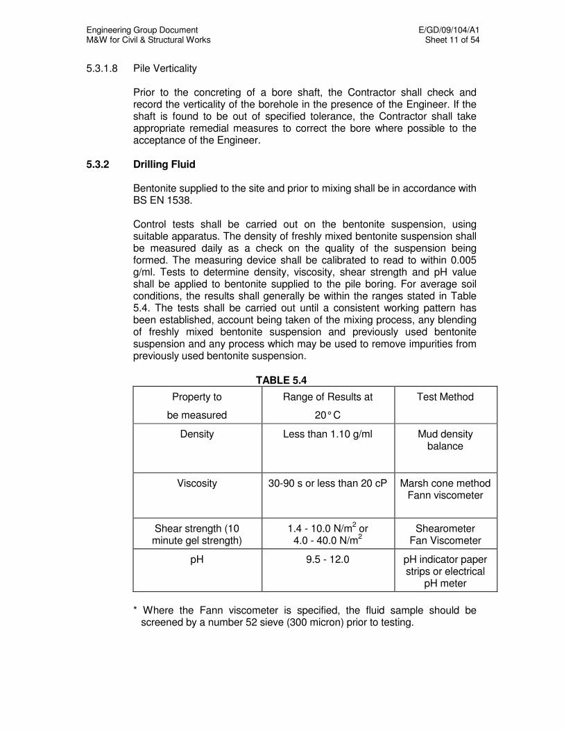
Engineering Group Document E/GD/09/104/A1 M&W for Civil & Structural Works Sheet 11 of 54
5.3.1.8 Pile Verticality Prior to the concreting of a bore shaft, the Contractor shall check and
record the verticality of the borehole in the presence of the Engineer. If the shaft is found to be out of specified tolerance, the Contractor shall take appropriate remedial measures to correct the bore where possible to the acceptance of the Engineer.
5.3.2 Drilling Fluid Bentonite supplied to the site and prior to mixing shall be in accordance with
BS EN 1538. Control tests shall be carried out on the bentonite suspension, using
suitable apparatus. The density of freshly mixed bentonite suspension shall be measured daily as a check on the quality of the suspension being formed. The measuring device shall be calibrated to read to within 0.005 g/ml. Tests to determine density, viscosity, shear strength and pH value shall be applied to bentonite supplied to the pile boring. For average soil conditions, the results shall generally be within the ranges stated in Table 5.4. The tests shall be carried out until a consistent working pattern has been established, account being taken of the mixing process, any blending of freshly mixed bentonite suspension and previously used bentonite suspension and any process which may be used to remove impurities from previously used bentonite suspension.
TABLE 5.4
Property to
be measured
Range of Results at
20° C
Test Method
Density Less than 1.10 g/ml Mud density balance
Viscosity 30-90 s or less than 20 cP Marsh cone method Fann viscometer
Shear strength (10 minute gel strength)
1.4 - 10.0 N/m2 or
4.0 - 40.0 N/m2
Shearometer Fan Viscometer
pH 9.5 - 12.0 pH indicator paper strips or electrical
pH meter
* Where the Fann viscometer is specified, the fluid sample should be
screened by a number 52 sieve (300 micron) prior to testing.

Engineering Group Document E/GD/09/104/A1 M&W for Civil & Structural Works Sheet 12 of 54
5.3.3 Determination of Bored Pile Length Each pile shall be installed to a depth of a penetration such as to develop
the load carrying capacity to the required factor of safety. For end bearing piles, a socket of at least 1m depth shall be formed into
the material that provides the end bearing. The length of the piles shall not be finalised before pile load tests of
preliminary piles have been completed. Where site investigation has been specified for assessing ground conditions for piling, piles shall not be constructed prior to the completion of the site investigation.
The Contractor shall engage an experienced Geotechnical Engineer with a
minimum of five years foundation experience to supervise the piling works and to verify the ground conditions and confirm the pile founding level. The pile founding level shall be acceptable to the Engineer.
5.3.4 Concreting and Extraction of Casing 5.3.4.1 Workability of Concrete Temporary casings shall be extracted before the initial setting time of the
concrete expires and when the concrete remains sufficiently workable to ensure that it is not lifted.
5.3.4.2 Concrete Level When the casing is being extracted, a sufficient quantity of concrete shall be
maintained within it to ensure that pressure from external water, drilling fluid or soil is exceeded and that the pile is neither reduced in section nor contaminated.
Concrete shall be placed continuously as the casing is extracted until the
desired head of concrete is obtained. No concrete shall be placed in the boring once the bottom of the casing has been lifted above the top of the concrete.
Where two or more discontinuous lengths of casing (double casing) are
used in the construction, the proposed method of working shall be acceptable to the Engineer.
5.3.4.3 Water Levels In the event of the ground water level being higher than the required pile
head casting level shown on the Drawings, the Contractor shall submit his proposals for acceptance prior to placing concrete. The pile head shall not be left below the ground water level unless acceptable precautions are taken.
Engineering Group Document E/GD/09/104/A1 M&W for Civil & Structural Works Sheet 13 of 54
5.3.5 Temporary Backfilling After each pile has been cast, any empty bore remaining shall be protected
and shall be carefully backfilled as soon as possible with acceptable materials.
5.3.6 Debonding of Bored Piles Debonding of bored piles, where required, shall follow the details in the
Code of Practice for Railway Protection. 5.4 DRIVEN PILES 5.4.1 Marking of Driven Piles All piles, including temporary casings subsequently to be withdrawn, shall
be marked at intervals of 1 metre along their length prior to pitching. In addition, the top 3 metres shall be marked at intervals of 250mm.
Steel piles shall be marked to show grade of steel, length and identification
number as appropriate. Precast concrete piles shall be marked to show their identification number,
length and date of casting. Prestressed concrete piles shall be marked with the prestressing force applied.
5.4.2 Handling and Pitching of Driven Piles Piles shall not be lifted other than by slinging from accepted lifting holes or
points. For each section lifting points shall be clearly marked. Concrete shall at no time be subjected to loading, including its own weight,
which will induce a compressive stress in it exceeding 0.33 of its strength at the time of loading. For this purpose the assessment of the strength of the concrete and of the stresses produced by the loads shall be subject to the acceptance of the Engineer.
Before the commencement of driving, each pile (or the driving tube) and the
leaders or guides of the pile frame shall be checked for correct rake or plumb and such rake or plumb shall be maintained during driving. At no time during the driving operation shall the centre of the monkey or hydraulic ram be more than 40 mm off the centre of the pile being driven.
5.4.3 Strength of Piles Piles shall not be driven until the concrete has achieved the specified
characteristic strength.
Engineering Group Document E/GD/09/104/A1 M&W for Civil & Structural Works Sheet 14 of 54
5.4.4 Pile Shoes The first section of each pile shall be provided with a pointed co-axial shoe
made of either steel or chill hardened cast iron. Cast iron pile shoes shall be made from chill hardened iron as used for
making grey iron castings to BS EN 1561, Grade 150. The chilled iron point shall be free from major blowholes and other surface defects.
Steel pile shoes shall be manufactured from steel to BS EN 10025, Grade
S275JO. Cast steel piles shoes shall be of steel to BS 3100, Grade A. Straps or other
fastenings to cast pile shoes shall be of steel to BS EN 10025, Grade S275JO, and shall be cast into the point to form an integral part of the shoe.
5.4.5 Leaders and Trestles At all stages during driving and until incorporation in the superstructure, the
pile shall be adequately supported and restrained by means of leaders, trestles, temporary supports or other guide arrangements to maintain position and alignment and to prevent buckling. These arrangements shall be such that damage to the pile does not occur.
5.4.6 Performance of Driving Equipment The Contractor shall satisfy the Engineer regarding the suitability, efficiency
and energy of the driving equipment. 5.4.7 Length of Piles The Contractor may, if accepted, provide each pile in more than one length,
the first length or subsequent lengths being extended during an interval in the pile driving operation. The sections used shall be of standard lengths and the number of joints shall not exceed three numbers, unless otherwise accepted by the Engineer.
5.4.8 Driving Procedure and Redrive Checks Each pile shall be driven continuously until the specified or accepted set
and/or depth has been reached. The Engineer may permit the suspension of driving if he accepts that the rate of penetration prior to the cessation of driving will be substantially re-established on its resumption or if he accepts that the suspension of driving is beyond the control of the Contractor. A follower (long dolly) shall not be used unless accepted, in which case the Engineer will require the set to be revised to take into account the reduction in the effectiveness of the hammer blow.
Engineering Group Document E/GD/09/104/A1 M&W for Civil & Structural Works Sheet 15 of 54
The Contractor shall inform the Engineer without delay if an unusual change
in driving characteristics is noted. A detailed record of the driving resistance over the full length of the next nearest available pile shall be taken if required.
At the start of work and in a new area or section, sets shall be taken at
intervals during the last 3 metres of the driving to establish the behaviour of the piles.
The Contractor shall give adequate notice and provide all facilities to enable
the Engineer to check driving resistance. A set shall be taken only in the presence of the Engineer unless otherwise accepted.
Redrive checks, if required, shall be carried out to an accepted procedure. 5.4.9 Final Set The final set of each pile shall be recorded as the penetration in millimetres
per 10 blows. When a final set is being measured, the following requirements shall be
met:- (a) The exposed part of the pile shall be in good condition without damage
or distortion. (b) The dolly and packing, if any, shall be in sound condition. (c) The hammer blow shall be in line with the pile axis and the impact
surfaces shall be flat and at right angles to the pile and hammer axis. (d) The hammer shall be in good condition and operating correctly. (e) The temporary compression of the pile shall be recorded if required. (f) When required by the Engineer, a dummy level should be available in
instances where the Engineer is of the opinion that the conventional method using graph paper and pencil to take the final set may be grossly inaccurate.
5.4.10 Driving Sequence and Risen Piles Piles shall be driven in an accepted sequence to minimise the detrimental
effects of heave and lateral displacement of the ground. When required, levels and measurements shall be taken to determine the
movement of the ground or any pile resulting from the driving process.
Engineering Group Document E/GD/09/104/A1 M&W for Civil & Structural Works Sheet 16 of 54
When a pile has risen as a result of adjacent piles being driven, the Contractor shall submit to the Engineer his proposals for correcting this and the avoidance of it in subsequent work.
5.4.11 Preboring If preboring is specified the pile shall be pitched into a hole prebored to the
depth shown on the Drawings. 5.4.12 Jetting Jetting shall be carried out only when the Contractor's detailed proposals
have been accepted, and not over the last 3 m of penetration 5.5 STEEL PILES 5.5.1 Pile Sections and Pile Dimensions For standard rolled sections, the dimensional tolerances and weight shall
comply with the relevant standards. For proprietary sections, the dimensional tolerances shall comply with the manufacturer's standards. The rolling or manufacturing tolerances shall be such that the actual weight of sections does not differ from the theoretical weight by more than -2.5% to +5% unless otherwise accepted by the Engineer.
For a tubular pile where the loads will be carried by the wall of the pile, and
if the pile will be subjected to loads that induce reversal of stress during or after construction, the external dimensions at any section as measured by using a tape on the circumference shall not differ from the theoretical dimensions by more than -1% to +1%. The rolling or manufacturing tolerances shall be such that the actual weight of any section does not differ from the theoretical weight by more than -2.5% to +5%.
For a tubular pile where the load will be static and will be carried by the wall
of the pile or by a concrete core, the dimensions shall comply with API 5L. The rolling or manufacturing tolerances shall be such that the actual weight of any section does not differ from the theoretical weight by more than -3.5% to +10%.
5.5.2 Straightness of Piles For standard rolled sections the deviation from straightness shall not
exceed 1.04 (L - 4.5) where L is in metres and the deviation in millimetres. For proprietary sections made up from rolled sections the deviation from straightness shall not exceed 1/1000 of the length of the pile.

Engineering Group Document E/GD/09/104/A1 M&W for Civil & Structural Works Sheet 17 of 54
For tubular piles, the deviation from straightness shall not exceed 1/600 of a
length not exceeding 10 m. When two or more such lengths are joined, the deviation from straightness shall not exceed 1/960 of the completed length unless otherwise acceptable to the Engineer.
5.5.3 Fabrication of Piles The root edges or root faces of lengths of piles that are to be butt welded
shall not differ by more than 25% of the thickness of piles not exceeding 12mm thick or by more than 3mm for piles thicker than 12mm. When piles of unequal thickness are to be butt welded, the thickness of the thinner material shall be the criterion.
Pile lengths shall be set up so that the differences in dimensions are
matched as evenly as possible. 5.5.4 Matching of Pile Lengths Longitudinal seam welds and spiral seam welds of lengths of tubular piles
forming a completed pile shall, whenever possible, be evenly staggered but if, in order to obtain an acceptable match of the ends of the piles or the specified straightness, the longitudinal seams or spiral seams are brought closely to one alignment at the joint, then they shall be staggered by at least 100mm.
5.5.5 Inspection and Test Certificates The Contractor shall provide the Engineer with test certificates, analyses
and mill sheets. The Contractor shall ensure that adequate notice be given to the Engineer when the processes can be inspected or tests can be witnessed.
The Engineer has the right to inspect and test at any stage of the
manufacturing processes provided that, once he has been notified when the materials will be ready for inspection, any delay in his attendance does not cause delay to or disrupt the production processes.
5.5.6 Welding All welding to steel pile sections shall be to the requirements of Chapter
12 Structural Steelwork. For a pile where the loads will be static and where the pile will receive
lateral support, or where the load will be carried by a concrete core, radiographs will not be required unless specified, but welds shall be capable of withstanding handling, driving and design load stresses. Radiographic tests shall otherwise be carried out where proposed by the Contractor and accepted by the Engineer.

Engineering Group Document E/GD/09/104/A1 M&W for Civil & Structural Works Sheet 18 of 54
5.5.7 Fabrication of Piles on Site When the pile lengths are to be made up on the site, all test procedures
and dimensional tolerances shall conform to the Specification for the supply of pile material. Adequate facilities shall be provided for supporting and aligning the lengths of pile.
5.5.8 Strengthening of Piles The strengthening to the toe of a pile in lieu of a shoe or the strengthening
of the head of a pile shall be made from material of the same grade as the pile unless otherwise accepted.
5.5.9 Longitudinal Welded Piles 5.5.9.1 Welded Tube Piles Acceptance shall be obtained if different edge preparation from that shown
on the Drawings is required for use with automatic welding machines or because of the method of rolling.
All welds shall be full penetration butt welds and, with the exception of
continuous tube-making processes, longitudinal welds shall be made with the extension plates at the starting and finishing points of each seam.
5.5.9.2 Welded Box Piles and Proprietary Sections Welded box piles or proprietary sections made up from two or more hot
rolled sections shall be welded in accordance with the manufacturer's standards.
5.5.9.3 Weld Check on Welded Piles During production of longitudinally welded tube piles, at least one
radiograph approximately 300mm long shall be required on each completed length as a spot check on weld quality. This shall be taken on a circumferential or longitudinal weld and its position shall be as directed by the Engineer.
Radiographs shall be carried out where proposed by the Contractor and
accepted by the Engineer. 5.5.10 Spirally Welded Piles Prior to forming a spirally welded pile the edges of the strip shall be straight.
The forming and welding process shall be accepted. Before fabrication commences, tests as required by the Engineer in accordance with the standards for forming and welding shall be made to ensure that the welding procedure is acceptable.
Engineering Group Document E/GD/09/104/A1 M&W for Civil & Structural Works Sheet 19 of 54
The Contractor shall satisfy the Engineer that all production welding is of sound quality. One of the following tests shall be carried out: -
(a) For tubes of wall thickness 12mm or less, three spot check radiographs,
one at each end of each length of the tube as manufactured and one at a position accepted by the Engineer.
(b) For tubes of any wall thickness, continuous ultrasonic examination over
the whole weld, supplemented where necessary by radiographs to investigate defects revealed by the ultrasonic examination.
If the results of any weld test do not conform to the specified requirements,
two additional specimens from the same length of pile shall be tested. In the case of failure of one or both of these additional tests, the length of pile covered by the tests shall be rejected.
5.5.11 Pile Coatings Where required, pile coating shall be in accordance with Chapter 12:
Structural Steelwork. 5.5.12 Handling and Storage of Piles All piles within a stack shall be in groups of the same length and on
accepted supports. All operations such as handling, transporting and pitching of piles shall be carried out in a manner such that damage to piles and their coatings are minimised.
5.5.13 Preparation of Piles Heads If a steel superstructure is to be welded to piles, the piles shall be cut to
within 10mm of the levels shown on the Drawings. If piles are to be encased in concrete they shall be cut to within 20mm of the levels shown on the Drawings, and protective coatings shall be removed from the surface of the pile heads down to a level 100mm above the soffit of the concrete.
5.6 TIMBER PILES 5.6.1 Pressure Treated Timber Piling 5.6.1.1 Pile Material Pressure Treated Timber Piles shall be of the Kempas or Keruing species
and shall not be of a lesser quality than the Select Structural Grades specified in Section J - Stress Grading, Part III of the Malayan Grading Rules for Sawn Hardwood Timber.
Engineering Group Document E/GD/09/104/A1 M&W for Civil & Structural Works Sheet 20 of 54
All piles shall be branded with a burnt brand impression. This brand shall
be sufficiently comprehensive and shall contain such trademarks, manufacturer's name and identification numbers as to allow the piles to be identified.
The Contractor shall submit the manufacture's specification certificate and
pile samples for piles supplied by him for acceptance by the Engineer before any piles are brought onto the site.
5.6.1.2 Preservative Treatment 5.6.1.2.1 Composition The composition of the preservative and method of application shall comply
with BS 4072 "Specification for Wood Preservation by means of Water Borne Copper / Chrome / Arsenic Compositions".
The composition of the preservative shall be Type 2 of BS 4072. 5.6.1.2.2 Application The piles shall be pressure impregnated at a pressure of not less than 12.6
kg/cm2 nor more than 15.5kg/cm
2 with a suitable wood preservative in
accordance with BS 4072. After impregnation, only piles conforming to Clauses 5.6.1.2.3 and 5.6.1.2.4 hereunder shall be deemed to have been treated in accordance with Specification.
5.6.1.2.3 Penetration A sample boring shall be taken on a heartwood face from the quarter point
of all treated piles and shall give evidence of continuous and substantially even penetration of the preservative for the full depth of the treated zone with a minimum penetration of 25 mm on the heartwood face when determined in accordance with Clause G3 or G4 of BS 4072.
5.6.1.2.4 Retention The preservative retention by analysis in the outermost 25mm of a boring
shall not be less than 16kg/m3 when determined by analytical methods in
accordance with Appendix D of BS 4072. Analysis shall preferably be undertaken using X-ray or atomic Spectrophotometric techniques.
5.6.1.2.5 Plugging Sample Holes All holes made for determining penetration and retention of preservative
shall be filled with preservative solution and closed with tight fitting treated wooden plugs and secured with a multi-toothed anti-splitting plate of suitable size.
Engineering Group Document E/GD/09/104/A1 M&W for Civil & Structural Works Sheet 21 of 54
5.6.1.3 Lifting and Stacking All piles shall be stacked in an area accepted by the Engineer, and shall be
adequately protected and placed on trestles or rests. 5.6.1.4 Equipment and Plant The Contractor shall provide all frames, equipment, lifting, and driving
devices with maintenance, and supply all fuel, with other plant and labour necessary for the driving of piles.
5.6.1.5 Tolerance, Straightness and Joints
(a) Tolerance The tolerance allowed for sizes of piles shall be as specified in BS 5268. (b) Straightness
(i) Measurement: The extent of curvature is determined by measuring the maximum deviation from a tightly stretched string or wire joining the mid-points of butt and toe.
(ii) Permissible Limits: In piles of lengths 6m and above, maximum
deviation shall not exceed 38mm. In piles of lengths below 6m, maximum deviation shall not exceed 25mm, i.e. the wire/string shall fall within 25mm of the centre line of the pile.
(c) Pile Joints
Pile joints when required shall be made by using a mild steel welded box joint 450mm long of 4.5mm thick plates and fabricated 3mm undersize of the pile cross-sectional dimensions. The joint and the end of the piles to be joined shall be constructed so that the necessary strength and stiffness are developed at the joint. The Contractor shall submit details of the pile joint to the Engineer for acceptance.
5.6.1.6 Pile Position Piles shall be driven accurately to the position indicated on the Drawings.
Any pile found to be greater than 75mm out of true position at pile cut off level or more than 1:100 from the vertical or from the required rake, whichever is applicable, shall be deemed to be defective.
Particular care shall be taken to ensure that the pile frame is vertical or at
the required rake during driving.

Engineering Group Document E/GD/09/104/A1 M&W for Civil & Structural Works Sheet 22 of 54
5.6.1.7 Driving of Timber Piles The Contractor shall submit set calculations using a dynamic formula that is
acceptable to the Engineer. Each pile shall be driven to the accepted set. The pile head shall be adequately protected during driving to the
acceptance of the Engineer so that "brooming" does not occur. Driving shall be a continuous process and no stoppage shall be made
during the driving of a complete pile length other than for extension of the piles.
The Contractor shall supply the Engineer with a full description of the
proposed driving equipment, crews and inspectors. The Engineer may order the removal or replacement of any equipment or staff whenever he thinks that such equipment and/or staff are not suitable for the works.
Anti-split nail plates not less than 18 gauge thick and of suitable size shall
be fitted to the butt and toe of each section of pile. Where a drop hammer is employed, it shall be the free fall type. The
hammer rope shall not be 'snatched' before the hammer has completed its full drop. The weight of the hammer shall be at least 3 times as much as the pile but in no case shall it weigh less than 1.0 tonne with an overall drop of 900mm.
When piles are driven below the leads of the pile frame, the use of a
follower shall require the acceptance of the Engineer. Driving of piles shall be stopped immediately on any cracking of the pile
head. When fissures appear in a pile while it is being driven, the pile shall be rejected.
5.6.1.8 Replacement of Defective Piles Where a pile is broken or found to be defective due to inaccurate
positioning, the Contractor shall drive an additional pile or piles to the acceptance of the Engineer.
5.6.1.9 Cut off Level of Piles Piles shall be cut off square to sound wood at the levels indicated on the
Drawings. The cut off head shall be given two flood coats of accepted preservative allowing each application to soak into the end grain completely. Approximately one hour should be allowed between applications. After the preservative application has dried, the pile head shall be heavily coated with accepted bituminous waterproofing compound for the whole depth that the pile will be encased in the pile cap.
All cut off piles shall be removed from the Site.
Engineering Group Document E/GD/09/104/A1 M&W for Civil & Structural Works Sheet 23 of 54
5.6.1.10 Load Testing of Timber Piles A minimum of two pile tests shall be required; one before commencement
of the piling works. The location for each test pile shall be proposed by the Contractor and accepted by the Engineer. No interchange of test piles will be permitted. The set to be achieved to carry the design load shall be determined by the Contractor and accepted by the Engineer
Driving operations should be continuous, interrupted only as required to
make penetration measurements. Test piles shall not be driven nor tested without the presence of the Engineer. If the test pile is accepted, it may be incorporated into the structure. If the test pile is found to be unsatisfactory or misplaced, the pile shall be removed or abandoned.
One test pile will be selected for actual loading and testing before
commencement of the main piling work. All equipment used during the performance of the specified pile loading tests shall be suitable, properly operated and maintained and shall be subject to acceptance of the Engineer prior to pile testing. All operations shall be constantly supervised by a qualified Engineer of the Contractor and personnel employed must have the required ability and training. Complete testing data shall be recorded.
The load shall be applied not earlier than 10 days after the driving of the pile
to be tested has been completed. Two dial gauges calibrated to 0.01 mm shall be used for settlement measurements. Measurements of settlements shall be taken and recorded immediately before and after each increment of load is added.
The proposed load test shall be 2 times the working load applied in
increments of 12.5% of the test load with 1-hour intervals and shall be maintained until no measurable settlement is observed in a period of 24 hours. Settlement readings made to an accuracy of 0.01 mm shall be taken before and after the application of each new load increment and at 2, 4, 8, 15, and 60 minutes until the application of the next load increment. Additional load increments shall not be applied until the rate of settlement under the previous increment is less than 0.05mm in 15 minutes.
Where the loading has been completed, the full test load shall remain on
the pile until there is less than 1.25mm of settlement in a 24-hour period. Settlement readings shall be taken at 6-hour intervals during the period and at the end of that period. Constant attention of the operator is required to maintain the specified pressure at all times during the load test.
Pile unloading test shall be performed after the total test load has been
reached. Loads shall be reduced in decrements of 25 % of the load test. Each subsequent load decrement shall not be removed until one hour has
elapsed. Pile movement shall be recorded to an accuracy of 0.01mm at time intervals following change of load at 0.5, 1, 2, 4, 15, 30 minutes and
Engineering Group Document E/GD/09/104/A1 M&W for Civil & Structural Works Sheet 24 of 54
every 30 minutes thereafter until change of load. Final rebound shall be recorded 24 hours after the entire test load has been removed.
5.6.1.11 Interpretation of Test Results When the pile test has been carried out as prescribed above, the pile so
tested shall be deemed to have failed if:
(a) The residual settlement after removal of the test load exceeds 6mm, or (b) The total settlement under the working load exceeds 13mm, or (c) The total settlement under test load (2 times design working load)
exceeds 38mm The Engineer’s interpretation and conclusions on the test results shall be
final. 5.6.1.12 Failure of Pile under Test Loading Piles, which fail the load test, shall be replaced by the Contractor by
compensating piles, to the acceptance of the Engineer. For every load test that fails, the Contractor shall carry out 2 additional load tests.
5.6.1.13 Warranty The Contractor shall with the pile manufacturer issue a warranty against
biological degrade, fungus and insect attack of the treated piles for a period of ten years from the date of Completion of the whole Works. The form of warranty shall be in accordance with the format shown in the General Specification.
5.6.2 Bakau Piling (Indigenous Timber Piles) 5.6.2.1 Pile Material Bakau piles shall be good, sound, straight piles, with fresh uninjured bark
and of reasonably uniform size. 5.6.2.2 Pile Lengths Bakau piles supplied shall be in lengths of 3m, 5m or 6m as required.
Measurement shall be from the squared-off head to the pointed end, with the under-sized end cut off.
5.6.2.3 Pile Diameter The pile diameter shall not be less than 75mm at the larger end, measured
within 150mm from its end. Such measurements shall not be over knobs and protuberances.
Engineering Group Document E/GD/09/104/A1 M&W for Civil & Structural Works Sheet 25 of 54
5.6.2.4 Examination of Piles Delivered All bakau piles shall be inspected and accepted by the Engineer before
being used. Bakau piles that have been rejected shall be removed from the site immediately.
5.6.2.5 Protection of Pile Heads The head of the pile shall be protected with a simple steel or cast iron ring
during driving. After completion of such driving, the head shall be properly squared and cut off to the required level.
5.6.2.6 Joints All piles shall be rigidly and securely joined with steel collars 300mm long
made out of 1.22mm thick (18 SWG) mild steel sheets with joints fully welded. Steel collars shall be completely coated with tar or bituminous paint.
5.6.2.7 Pile Driving Equipment Piles shall be driven by an accepted piling frame, with a "monkey" of an
accepted weight. The "monkey" used shall be of minimum 200kg in weight. 5.6.2.8 Driving All piles shall be driven vertically in a straight line, perfectly squared from
the face of the work and free from damage. The monkey shall be dropped from a height of 1m to 1.5m, such that the blows land squarely and centrally on the pile. The actual height of the drops shall be accepted by the Engineer.
During driving, the pile shall be effectively restrained from buckling.
Inclinations of the pile exceeding 1: 75 shall be rejected. Piles shall not be forcibly corrected to an acceptable position. 5.6.2.9 Pile Replacement All incorrectly driven piles and piles damaged during driving shall be
compensated to the acceptance of the Engineer. 5.7 PILE LOAD TESTING 5.7.1 General This Section deals with the testing of a pile by the application of a load or
force. It covers vertical and raking piles tested in compression (i.e. subjected to loads or forces in a direction such as would cause the pile to penetrate further into the ground), vertical or raking piles tested in tension

Engineering Group Document E/GD/09/104/A1 M&W for Civil & Structural Works Sheet 26 of 54
(i.e. subjected to forces in a direction such as would cause the piles to be extracted from the ground), and vertical raking piles tested in bending (i.e. subjected to horizontal forces). This Section does not apply to testing of timber piles which is given under 5.6.1.10 to 5.6.1.12 above.
Each preliminary bored test pile shall be uniform in diameter along its entire
shaft with overbreaks not exceeding 10% of its nominal diameter at any section. The percentage overbreak in the pile shall be computed as the percentage excess between the concrete volume discharged per truck as indicated by the concrete delivery docket and the resulting concrete displacement in the bored pile based on the nominal size of the piles. The test pile with overbreaks exceeding the specified allowable percentage shall be rejected at the discretion of the Engineer.
5.7.2 Definitions Allowable Load: the load which may be safely applied to a pile after taking
into account its ultimate bearing capacity, negative skin friction, pile spacing, overall bearing capacity of the ground below and allowable settlement.
Kentledge: the dead weight used in a loading test. Maintained Load Test: a loading test in which each increment of load is held
constant either for a defined period of time or until the rate of movement (settlement or uplift) falls to a specified value.
Preliminary Pile: a pile installed before the commencement of the main
piling works or specific part of the Works for the purpose of establishing the suitability of the chosen type of pile and for confirming its design, dimensions and bearing capacity. Preliminary piles shall not be incorporated into the Works.
Working Test Load: a load applied to a selected working pile to confirm that
it is suitable for the load at the settlement specified. A working test load should not normally exceed 150% of the working load on a pile.
Reaction System: an arrangement of kentledge, piles, anchors or rafts that
provides a resistance against which the pile is tested. Test Pile: any pile to which a test is, or is to be, applied. Working Load: the service load, which the pile is designed to carry. 5.7.3 Safety Precautions 5.7.3.1 Personnel All tests shall be carried out only under the direction of an experienced and
competent supervisor, conversant with the test equipment and test

Engineering Group Document E/GD/09/104/A1 M&W for Civil & Structural Works Sheet 27 of 54
procedure. All personnel operating the test equipment shall have been trained in its use.
5.7.3.2 Kentledge Where kentledge is used, the Contractor shall construct the foundations for
the kentledge and any cribwork, beams or other supporting structures in such a manner that there will be no differential settlement, bending or deflection of an amount that constitutes a hazard to safety or impairs the efficiency of the operation. The kentledge shall be adequately bonded, tied or otherwise held together to prevent it from falling apart, or becoming unstable because of deflection of the supports.
The weight of kentledge shall be greater than the maximum test load and if
the weight is estimated from the density and volume of the constituent materials, an adequate factor of safety against error shall be allowed.
5.7.3.3 Tension Pile and Ground Anchors Where tension piles or ground anchors are used, the Contractor shall
ensure that the load is correctly transmitted to all the tie rods or bolts. The extension of rods by welding shall not be permitted unless it is known that the steel will not be reduced in strength by welding. The bond stresses of the rods in tension shall not exceed normal permissible bond stresses for the type of steel and grade of concrete used.
5.7.3.4 Testing Equipment The Contractor shall ensure that when the hydraulic jack and load
measuring device are mounted on the pile head, the whole system will be stable up to the maximum load to be applied. Means shall be provided to enable dial gauges to be read from a position clear of the kentledge stack or test frame in conditions where failure in any part of the system due to overloading, buckling, loss of hydraulic pressure etc. will not constitute a hazard to personnel.
The hydraulic jack, pump, hoses, pipes, couplings and other apparatus to be
operated under hydraulic pressure shall be capable of withstanding a test pressure of one and a half times the maximum working pressure without leaking.
The maximum test load or test pressure expressed as a reading on the
gauge in use shall be displayed and all operators shall be made aware of this limit.
5.7.4 Construction of a Preliminary Test Pile 5.7.4.1 Notice of Construction The Contractor shall give the Engineer at least 48 hours notice of the
commencement of construction of any preliminary pile.

Engineering Group Document E/GD/09/104/A1 M&W for Civil & Structural Works Sheet 28 of 54
5.7.4.2 Method of Construction Each preliminary test pile shall be constructed in a manner similar to that to
be used for the construction of the working piles, and by the use of similar equipment and materials. Any variation will only be permitted with prior acceptance of the Engineer.
Extra reinforcement and concrete of increased strength may be used subject
to the acceptance of the Engineer. 5.7.4.3 Instrumentation for Preliminary Piles The Contractor shall submit to the Engineer for acceptance, a full method
statement describing the testing equipment and procedure at least 14 days prior to the commencement of construction of a preliminary pile.
The preliminary piles shall be instrumented with vibrating wire strain gauges
and extensometer at every different geological strata and at intervals of not more than 3 metres. The strain gauges shall be installed in pairs at each level.
The strain gauges and extensometer shall be properly fixed to the
reinforcement cages of the piles, and protected from damage at all stages of pile construction.
Where preliminary piles are required for lateral load tests, an inclinometer
along the pile shaft shall also be installed. 5.7.4.4 Boring or Driving Record For each preliminary pile, a detailed record of the soils encountered during
boring, or of the progress during driving shall be made and submitted to the Engineer daily on the next working day.
Where the Engineer requires soil samples to be taken or in situ tests to be
made in bored pile, the Contractor shall give the results of such tests to the Engineer without delay.
5.7.4.5 Cut-off Level The pile shaft shall terminate at the cut-off level or at a level required by the
Engineer. The pile shaft shall be extended where necessary above the cut-off level of
working piles so that gauges and other apparatus to be used in the testing process will not be damaged by water or falling debris.
Where the pile shaft is extended above the cut-off level of a working pile in
a soil which would influence the load bearing capacity of the pile, a sleeve shall be installed and kept in place during testing to eliminate friction which
Engineering Group Document E/GD/09/104/A1 M&W for Civil & Structural Works Sheet 29 of 54
would not arise in the working pile. Alternatively, if the friction above the designed cut-off level can be calculated with reasonable accuracy, with the acceptance of the Engineer, a sleeve need not be used, the calculated friction must be taken into account in assessing the load bearing applied to the pile.
5.7.4.6 Pile Head Construction 5.7.4.6.1 Compression Test The pile head or cap shall be formed to give a plane surface which is
normal to the axis of the pile, sufficiently large to accommodate the loading and settlement-measuring equipment and adequately reinforced or protected to prevent damage from the concentrated application of load from the loading equipment.
The pile cap shall be concentric with the test pile; the joint between the cap
and the pile shall have a strength equivalent to that of the pile. Sufficient clear space shall be made under any part of the cap projecting
beyond the section of the pile so that, at the maximum expected settlement, load is not transmitted to the ground except through the pile.
5.7.4.6.2 Tension Test The test load shall be axially transmitted to the pile. The connection between the pile and the loading equipment shall be
constructed in such a manner as to provide a strength equal to the maximum load which is to be applied to the pile during the test with an appropriate factor of safety on the structural design.
5.7.5 Preparation of a Working Pile to be Tested The Contractor shall cut down or prepare the pile for testing as required by
the Engineer in accordance with Clause 5.7.4.5 and 5.7.4.6. 5.7.6 Concrete Test Cubes Three test cubes shall be made from the concrete used in each of the
preliminary test piles and working piles as directed by the Engineer. If a concrete cap is cast separately from a preliminary pile or a working pile, a further three cubes shall be made from this concrete. The cubes shall be made and tested in accordance with BS 1881.
The pile test shall not be started until the sample cubes have acquired
strength such that the applied direct stress is less than 0.5 times the cube strength. This requirement shall apply to both pile and pile cap.
Engineering Group Document E/GD/09/104/A1 M&W for Civil & Structural Works Sheet 30 of 54
5.7.7 Reaction Systems 5.7.7.1 Compression Tests Compression tests shall be carried out using kentledge, tension piles or
specially constructed anchorage. Kentledge shall not be used for tests on raking piles.
Where kentledge is to be used, it shall be supported on cribwork disposed
around the pile head so that its centre of gravity is on the axis of the pile. The bearing pressure under supporting cribs shall be such as to ensure stability of the kentledge stack, and if necessary, the Contractor shall provide a pile support system to the kentledge. Kentledge shall not be carried directly on the pile head, except when directed by the Engineer.
5.7.7.2 Tension Tests Tension tests shall be carried out using compression piles or rafts
constructed on the ground. The inclined reaction piles, anchors, or rafts may be used subject to the acceptance of the Engineer. In all cases, the resultant force of the reaction system shall be co-axial with the test pile.
5.7.7.3 Working Piles Working piles shall not be used as reaction piles. 5.7.7.4 Spacing Where kentledge is used for loading vertical piles in compression, the
distance from the edge of the test pile to the nearest part of the crib supporting the kentledge stack in contact with the ground shall not be less than 1.5 m.
The centre to centre spacing of vertical reaction piles, from a test pile shall
not be less than 3 times the diameter of the test pile/the reaction piles or 2m, whichever is the greatest. Where a pile to be tested has an enlarged base, the same criterion shall apply with regard to the pile shafts, with the additional requirement that the surface of reaction pile shall not be closer to the base of the test pile by more than one half of the enlarged base diameter.
Where ground anchors are used to provide a test reaction for loading in
compression, no part of the section of the anchor transferring load to the ground shall be closer to the test pile than 3 times the diameter of the test pile. Where the pile to be tested has an enlarged base, the same criterion shall apply with regard to the pile shaft, with the additional requirement that no section of the anchor transferring load to the ground shall be closer to the pile base by more than the base diameter.
Engineering Group Document E/GD/09/104/A1 M&W for Civil & Structural Works Sheet 31 of 54
5.7.7.5 Adequate Reaction The size, length and number of the piles or anchors, or the area of the rafts,
shall be adequate to transmit the maximum test load to the ground in a safe manner without excessive movement or influence on the test pile.
5.7.7.6 Care of Piles The method employed in the installation of any reaction piles, anchors or
rafts shall be such as to prevent damage to any test pile or working pile. 5.7.7.7 Loading Arrangement The loading arrangement shall be designed to transfer the test load safely to
the test pile. Full details shall be submitted to the Engineer prior to any work related to the testing process being carried out on the site.
5.7.8 Equipment for Applying Load The equipment for applying load shall consist of hydraulic rams or jacks.
The hydraulic rams or jacks shall be arranged in conjunction with the reaction system to deliver an axial load to the test pile. The complete system shall be capable of transferring the maximum load required for the test.
5.7.9 Measurement of Load The load shall be measured by a load measuring device and by a calibrated
pressure gauge included in the hydraulic system. Readings of both the load measuring device and the pressure gauges shall be recorded. In interpreting the test data, the values given by the load measuring device shall normally be used; the pressure gauge readings are required as a check.
The load measuring device may consist of a proving ring, load measuring
column, pressure cell or other appropriate system. A spherical seating shall be used in conjunction with any devices that are sensitive to eccentric loading; care must be taken to avoid any risk of buckling. Load measuring devices and jacks shall be short in axial length in order to achieve the best possible stability; the Contractor shall pay attention to details in order to ensure that axial loading is maintained.
The load measuring devices shall be calibrated before and after each series
of tests, whenever adjustments are made to the device or at intervals appropriate to the type of equipment. The pressure gauge and hydraulic jack shall be calibrated together. Certifications of calibrations shall be supplied to the Engineer.
The Engineer’s acceptance shall be obtained before any modification of this
procedure is adopted.
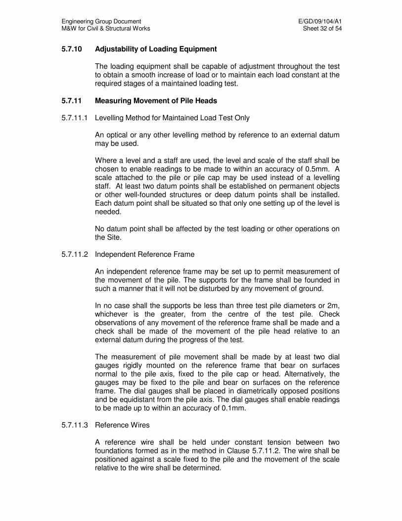
Engineering Group Document E/GD/09/104/A1 M&W for Civil & Structural Works Sheet 32 of 54
5.7.10 Adjustability of Loading Equipment The loading equipment shall be capable of adjustment throughout the test
to obtain a smooth increase of load or to maintain each load constant at the required stages of a maintained loading test.
5.7.11 Measuring Movement of Pile Heads 5.7.11.1 Levelling Method for Maintained Load Test Only An optical or any other levelling method by reference to an external datum
may be used. Where a level and a staff are used, the level and scale of the staff shall be
chosen to enable readings to be made to within an accuracy of 0.5mm. A scale attached to the pile or pile cap may be used instead of a levelling staff. At least two datum points shall be established on permanent objects or other well-founded structures or deep datum points shall be installed. Each datum point shall be situated so that only one setting up of the level is needed.
No datum point shall be affected by the test loading or other operations on
the Site. 5.7.11.2 Independent Reference Frame An independent reference frame may be set up to permit measurement of
the movement of the pile. The supports for the frame shall be founded in such a manner that it will not be disturbed by any movement of ground.
In no case shall the supports be less than three test pile diameters or 2m,
whichever is the greater, from the centre of the test pile. Check observations of any movement of the reference frame shall be made and a check shall be made of the movement of the pile head relative to an external datum during the progress of the test.
The measurement of pile movement shall be made by at least two dial
gauges rigidly mounted on the reference frame that bear on surfaces normal to the pile axis, fixed to the pile cap or head. Alternatively, the gauges may be fixed to the pile and bear on surfaces on the reference frame. The dial gauges shall be placed in diametrically opposed positions and be equidistant from the pile axis. The dial gauges shall enable readings to be made up to within an accuracy of 0.1mm.
5.7.11.3 Reference Wires A reference wire shall be held under constant tension between two
foundations formed as in the method in Clause 5.7.11.2. The wire shall be positioned against a scale fixed to the pile and the movement of the scale relative to the wire shall be determined.
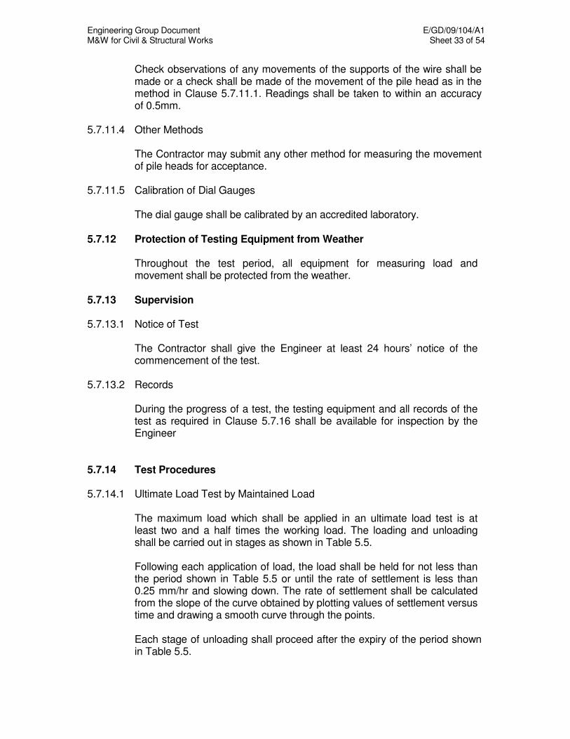
Engineering Group Document E/GD/09/104/A1 M&W for Civil & Structural Works Sheet 33 of 54
Check observations of any movements of the supports of the wire shall be made or a check shall be made of the movement of the pile head as in the method in Clause 5.7.11.1. Readings shall be taken to within an accuracy of 0.5mm.
5.7.11.4 Other Methods The Contractor may submit any other method for measuring the movement
of pile heads for acceptance. 5.7.11.5 Calibration of Dial Gauges The dial gauge shall be calibrated by an accredited laboratory. 5.7.12 Protection of Testing Equipment from Weather Throughout the test period, all equipment for measuring load and
movement shall be protected from the weather. 5.7.13 Supervision 5.7.13.1 Notice of Test The Contractor shall give the Engineer at least 24 hours’ notice of the
commencement of the test. 5.7.13.2 Records During the progress of a test, the testing equipment and all records of the
test as required in Clause 5.7.16 shall be available for inspection by the Engineer
5.7.14 Test Procedures 5.7.14.1 Ultimate Load Test by Maintained Load The maximum load which shall be applied in an ultimate load test is at
least two and a half times the working load. The loading and unloading shall be carried out in stages as shown in Table 5.5.
Following each application of load, the load shall be held for not less than
the period shown in Table 5.5 or until the rate of settlement is less than 0.25 mm/hr and slowing down. The rate of settlement shall be calculated from the slope of the curve obtained by plotting values of settlement versus time and drawing a smooth curve through the points.
Each stage of unloading shall proceed after the expiry of the period shown
in Table 5.5.

Engineering Group Document E/GD/09/104/A1 M&W for Civil & Structural Works Sheet 34 of 54
For any period when the load is constant, time and settlement shall be recorded immediately on reaching the load and at approximately 15 min intervals for 1 hr, at 30 min intervals between 1 hr and 4 hr and at 1 hr intervals between 4 hr and 12 hr after the application of the increment of the load.
Testing shall continue until the maximum test load has been reached or
when the settlement exceeds 10% of the pile diameter. 5.7.14.2 Working Load Test by Maintained Load The maximum load which shall be applied in a working load test on a
working pile is one and a half times the working load. The loading and unloading shall be carried out in stages as shown in Table 5.6.
Following each application of an increment of load, the load shall be held
for not less than the period shown in Table 5.6 or until the rate of settlement is less than 0.25mm/hr and slowing down. The rate of settlement shall be calculated from the slope of the curve obtained by plotting values of settlement versus time and drawing a smooth curve through the points.
Each stage of unloading shall proceed after the expiry of the period shown
in Table 5.6. For any period when the load is constant, time and settlement shall be
recorded immediately on reaching the load and at approximately 15 min intervals for 1 hr, at 30 min intervals between 1 hr and 4 hr and at 1 hr intervals between 4 hr and 12 hr after the application of the increment of the load.
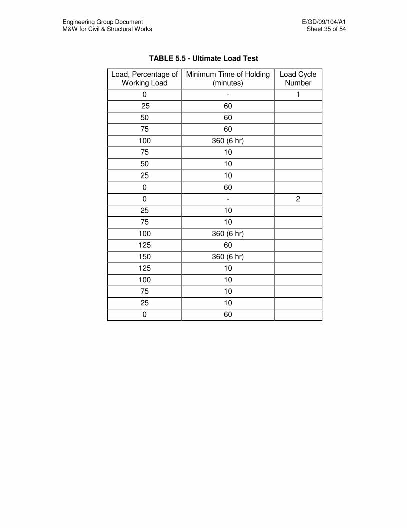
Engineering Group Document E/GD/09/104/A1 M&W for Civil & Structural Works Sheet 35 of 54
TABLE 5.5 - Ultimate Load Test
Load, Percentage of Working Load
Minimum Time of Holding (minutes)
Load Cycle Number
0 - 1
25 60
50 60
75 60
100 360 (6 hr)
75 10
50 10
25 10
0 60
0 - 2
25 10
75 10
100 360 (6 hr)
125 60
150 360 (6 hr)
125 10
100 10
75 10
25 10
0 60

Engineering Group Document E/GD/09/104/A1 M&W for Civil & Structural Works Sheet 36 of 54
TABLE 5.5 - Ultimate Load Test (Cont’d)
Load, Percentage of Working Load
Minimum Time of Holding (minutes)
Load Cycle Number
0 - 3
25 10
50 10
75 10
100 10
125 10
150 60
175 60
200 60
225 60
250 1440 (24 hrs)
200 10
150 10
100 10
50 10
0 30
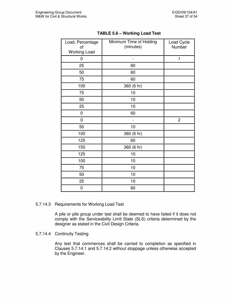
Engineering Group Document E/GD/09/104/A1 M&W for Civil & Structural Works Sheet 37 of 54
TABLE 5.6 – Working Load Test
Load, Percentage of
Working Load
Minimum Time of Holding (minutes)
Load Cycle Number
0 - 1
25 60
50 60
75 60
100 360 (6 hr)
75 10
50 10
25 10
0 60
0 - 2
50 10
100 360 (6 hr)
125 60
150 360 (6 hr)
125 10
100 10
75 10
50 10
25 10
0 60
5.7.14.3 Requirements for Working Load Test A pile or pile group under test shall be deemed to have failed if it does not
comply with the Serviceability Limit State (SLS) criteria determined by the designer as stated in the Civil Design Criteria.
5.7.14.4 Continuity Testing Any test that commences shall be carried to completion as specified in
Clauses 5.7.14.1 and 5.7.14.2 without stoppage unless otherwise accepted by the Engineer.
Engineering Group Document E/GD/09/104/A1 M&W for Civil & Structural Works Sheet 38 of 54
5.7.15 Testing Criteria 5.7.15.1 Failure of Piles Any pile which fails the load test shall be replaced by one or more piles by
the Contractor or as directed by the Engineer. If it is impractical or inadvisable to install substitute piles in place of a failed pile, the Contractor shall submit proposals to rectify the defect subject to the acceptance of the Engineer.
In addition, the Contractor shall at his expense carry out two more additional
working load tests. The piles for these tests shall be selected by the Engineer.
5.7.15.2 Faulty Pile Tests A load test shall be deemed to be faulty if any of the following occurs: -
(a) The loading and testing requirements of the Materials and Workmanship Specification are not met for any reason whatsoever.
b) If any test has to be discontinued due to :
(i) faulty jack or gauge, (ii) unstable support of the kentledge, (iii) cracking in or damage to the pile cap, (iv) incorrect or disturbed datum,
or any other causes, then the test shall be abandoned and the results
disregarded. In the event of a faulty test, a further test shall be carried out. 5.7.16 Presentation of Results 5.7.16.1 Results to be submitted Results to be submitted shall include:
(a) a summary in writing to the Engineer, unless otherwise directed, within 24 hours of the completion of the test. The summary shall give the period for which the load was held, the load and the maximum settlement or uplift recorded for a working load test by maintained load for each stage of loading.
(b) the completed schedule of recorded data as in Clause 5.7.16.2 within
seven days of the completion of the test.
Engineering Group Document E/GD/09/104/A1 M&W for Civil & Structural Works Sheet 39 of 54
5.7.16.2 Schedule of Recorded Data The Contractor shall provide information about the tested pile in accordance
with the following schedule where applicable. (a) General
- Site location - Contract identification - Proposed structure - Main Contractor - Piling Contractor - Engineer - Client - Date of test
(b) Pile Details
(i) All types of pile
- Identification (number and location) - Position relative to adjacent piles - Brief description of location (e.g. in cofferdam, in cutting, over
water) - Ground level at pile position - Head level at which test load is applied - Type of pile (e.g. precast reinforced concrete, steel H, bored in
place, driven in place, composite type) - Vertical or raking, compression or tension - Shape and size of cross section of pile, position of change in
cross section. - Shoe or base details - Head details - Length in ground - Level of toe - Any permanent casing or core
(ii) Concrete Piles
- Concrete mix - Aggregate type and source - Cement type - Slump - Cube test results for pile and cap - Date of casting of precast pile - Reinforcement
(iii) Steel Piles - Steel quality - Coating - Filling
Engineering Group Document E/GD/09/104/A1 M&W for Civil & Structural Works Sheet 40 of 54
(c) Installation Details
(i) All Piles
- Dates and times of boring, driving and concreting of test pile and adjacent piles.
- Unusual circumstances and difficulties - Date and time of casting concrete pile cap - Start and finish of each operation during driving or installation of
a pile and subsequent testing - Difficulties in handling, pitching and driving piles - Delays due to sea and weather conditions
(ii) Bored Piles
- Type of equipment used and method of boring - Temporary casing, method of installation and extraction. - Strata encountered during boring - Water encountered during boring - Method of placing concrete and conditions pertaining - Volume of concrete placed - Concrete level before and after extraction of casing
(iii) Driven Preformed Piles and Driven Cast In-Situ Piles
- Method of support of Pile and hammer (frame, hanging leaders, suspended hammer or other method)
- Driven length of pile or temporary casing at final set - Hammer type, size and weight - Dolly and packing, type and condition before and after driving - Driving log (depth, blows per 250mm, interruptions or breaks in
driving) - Final set - Redrive check, time interval and set - At final set and at redrive set, for drop or single acting hammer,
the length of the drop or stroke; for diesel hammer, the length of the stroke and the blows per minute; for double-acting hammer, the number of blows per minute
- Condition of pile head or temporary casing after driving - Use of a follower - Use of preboring - Use of jetting - Lengthening - Details of temporary casing - Concrete level before and after extraction of casing - Method of placing concrete and conditions pertaining.
(d) Test Procedure
- Weight of kentledge - Tension pile, ground anchor or compression pile details - Plan of test arrangements showing position and distances of
kentledge supports, rafts, tension or compression piles and reference frame to test pile.
Engineering Group Document E/GD/09/104/A1 M&W for Civil & Structural Works Sheet 41 of 54
- Jack capacity - Method of load measurement - Method(s) of penetration or uplift measurement - Working load test by Maintained Loading - Relevant dates and times
(e) Test Results
- In tabular form - In graphical form: load plotted against settlement (uplift), load
and settlement (uplift) plotted against time - Ground heave
(f) Site Investigation
- Site investigation report number - Borehole reference
5.7.16.3 Presentation of Graphical Results The scales used for plotting load/settlement (uplift) curves shall be such that
a settlement of 10 mm is equivalent to a load of 100 tonnes. The same scales shall be used for the load and settlement (uplift) against time curves.
5.7.16.4 Submission of Results to Borehole Information System (BIS) The Land Transport Authority has an intranet application called the
Borehole Information System (BIS). The BIS is a web-based system which stores and displays borehole information and pile load test (PLT) reports obtained from all pile tests.
The Contractor shall submit a Summary Report for each pile load test to
BIS. The Summary Report shall follow the template in Appendix 5.1. All information as listed in the template shall be submitted. Other PLT test results can also be attached to the Summary Report. The Summary Report and other attached reports shall be in PDF format and the graphs and raw data shall be in Excel format.
The Summary Report and attached reports shall be submitted in softcopy
in a diskette/CD with the following folder/file structure: Contract No./PLT XXX/Report_01 (Maximum 5 per PLT including
summary report) Sub-directory naming convention shall be as follows:
PLT XXX XXX = 001 to 999
Each test pile shall have its own complete reports. The Summary Report shall be named as Report_01. Other attached reports shall be named sequentially.
Engineering Group Document E/GD/09/104/A1 M&W for Civil & Structural Works Sheet 42 of 54
5.7.17 Removal of Ground Anchors and Cutting-Off of Temporary Piles On completion of a preliminary test, temporary piles shall be cut off 2m
below ground level, and the ground made good with suitable material. All ground anchors shall be removed unless otherwise instructed by the
Engineer. 5.7.18 Dynamic Load Testing of Piles Using Stress Wave Measurements The Contractor shall engage an accredited company, accepted by the
Engineer, to carry out dynamic testing of piles. During dynamic pile testing, the Contractor shall measure pile penetration
per blow and temporary compression with a card attached to the pile. 5.7.18.1 Testing Requirements Piles may be tested during the entire driving process, at the end of driving or
during restrike. Computer analysis of the field measurements to obtain the pile resistance distribution and vertical load against displacement relationship shall be carried out on all piles which are dynamically tested.
Working piles selected for dynamic testing shall be tested to 2.0 times the
working load. The Contractor shall be responsible for providing a suitable hammer system to test the piles to the required test load. The hammer system should, amongst others, consist of adequately heavy hammer with a controlled drop to limit the driving stresses in the pile. In general, the energy provided on to the pile during restrike tests shall not be less than that used to initially drive the pile.
5.7.18.2 Method of Testing The dynamic testing of piles shall be carried out with an established testing
system accepted by the Engineer. The proposed system together with its method of testing, list of equipment and C.V.s of personnel involved shall be submitted to the Engineer for his prior acceptance. The test shall be conducted by a qualified engineer on site with no less than five years of dynamic pile testing experience.
The equipment employed shall be capable of measuring the pile force and
velocity against time. The signals from the transducers during the impact shall be recorded to
allow for the determination of the force and velocity versus time traces to be displayed. The force, velocity, displacement and the energy transferred to the pile against time shall be produced and plotted on-site in graphical form. Soil resistance shall be computed for every blow.
Engineering Group Document E/GD/09/104/A1 M&W for Civil & Structural Works Sheet 43 of 54
5.7.18.3 Results of the Test The results of the dynamic load tests shall be submitted by the tester. The
complete field results and graphs shall be submitted immediately and computer analysis results 3 days after the test. The detailed report, which should include the interpretation, analysis and correlation with static load test results, shall be submitted within 7 days after testing. The format of all submissions shall be acceptable to the Engineer.
The piles, which are dynamically tested, shall be deemed to have failed if
the measured resistance of the pile is less than 2.0 times the designed working load or if any part of the piles is damaged during driving or testing. The Engineer shall review the results and his interpretation shall be final. For each pile, which has failed, substitute compensating piles shall be proposed by the Contractor for acceptance by the Engineer. If it is impractical or inadvisable to install substitute piles in place of a failed pile, the Contractor shall submit alternative proposals. In addition, the Contractor shall carry out an additional dynamic pile load test on another pile as selected by the Engineer.
5.7.19 Lateral Load Test 5.7.19.1 Lateral Load Test on Preliminary Piles Where piles are subject to a design horizontal load exceeding 400kN or
10% of the allowable vertical pile capacity, then lateral load tests on preliminary piles shall be carried out. The reaction and testing system to apply a horizontal load on the preliminary pile shall be designed by the Contractor. An inclinometer shall be installed in the preliminary pile and monitored during the lateral load test. The horizontal lateral load on the pile head shall be parallel to a pair of strain gauges already installed in the pile.
The testing procedures shall be the same as that given in Clause 5.7.19.2
except that only one load cycle is required with each load increment to be held for 1 hour until two times the lateral working load or 300mm pile top deflection, whichever occurs first. The inclinometer and strain gauges in the pile shall be monitored at every load step.
5.7.19.2 Lateral Load Tests on Working Piles Where piles are subject to a design horizontal load exceeding 400kN or
10% of the allowable vertical pile capacity, then lateral load tests on working piles shall be carried out. Lateral load tests shall be undertaken on an adjacent pair of piles. Such testing shall be undertaken by either jacking the piles apart or pulling them together.
The test load shall be applied at or within 0.5 metres of the pile cap soffit
level. The test load shall be equal to the lateral working load of the pile. Pile deflections shall be measured parallel to the direction of the applied load such that the movement of each pile is measured in absolute terms and not

Engineering Group Document E/GD/09/104/A1 M&W for Civil & Structural Works Sheet 44 of 54
as a relative movement between piles. Dial gauges and load cells used shall be accurate to 0.1mm and 10kN for deflection and load measurements respectively.
Deflection shall be recorded for every 12.5% of the test load, during both
loading and unloading. Where specified on the Drawings, the rotation of the pile shall be recorded at the same increments. Loading sequence shall be carried out in 2 cycles. At the first cycle, the pile shall be tested to 75% of the test load and then reduced to zero. At the second cycle the pile shall be tested to 100% of the test load and then reduced to zero.
For both loading cycles, the load shall only be increased if the rate of
movement is less than 0.2mm in 20 minutes and subject to a minimum holding period of 20 minutes at the end of each incremental increase. The minimum holding period may be reduced to 10 minutes if the rate of movement is less than 0.1mm in 10 minutes for every load increment previously applied on the first cycle during the second loading cycle. The minimum holding period shall be 3 hours at the maximum load for both the first and second loading cycle. The minimum holding period during unloading shall be 20 minutes at the end of each incremental decrease for both load cycles. Presentation of results shall be consistent with Clause 5.7.16 modified as required for lateral load testing and as accepted by the Engineer.
5.7.19.3 Abandonment of Lateral Load Tests A lateral load test shall be abandoned if any one of the following occurs: (a) faulty jack or gauges (b) unstable support of loading apparatus (c) cracking in or damage to the pile (d) incorrect or disturbed datums or any other cause. If a test is abandoned a replacement test shall be carried out. The originally
tested pair of piles shall not be re-tested unless in the opinion of the Engineer such re-testing will give representative results for the piles as if they had not previously been tested.
5.7.19.4 Failure of Lateral Load Tests on Working Piles A pile or pile group under lateral load test shall be deemed to have failed if
the lateral deflection or rotation at the pile cap soffit level exceeds the Serviceability Limit State (SLS) criteria at the test load. In this event, remedial works shall be carried out as required in Clause 5.7.19.5.
In the event that a pile fails the working load test the Contractor shall carry
out two additional lateral load tests on laterally loaded working piles. The Engineer shall select the piles for these tests.

Engineering Group Document E/GD/09/104/A1 M&W for Civil & Structural Works Sheet 45 of 54
5.7.19.5 Remedial Works for Excessive Deflections In the event that a pile fails a lateral working load test, the Contractor shall
carry out remedial measures. Working piles, which have failed the lateral load tests and have had
remedial measures applied shall then be re-tested. This re-test shall not be taken as one of the additional tests required under Clause 5.7.19.4. All piles for which the particular lateral load test was agreed to be representative, shall have similar remedial measures applied.
Remedial measures may consist of: (a) Excavation of all materials for a distance of not less than 5 metres from
pile face, around the entire pile to minimum 1m below the level of the pile cap soffit. The width of excavation shall be the same on all sides of the pile.
(b) Backfilling and compaction of the excavation hard against the pile in
layers. The material in backfilling shall have a minimum value of modulus of deformation of 45MN/m
3, as determined by a plate bearing
test, following compaction to the requirements of Chapter 4: Earthworks. The Contractor may propose alternative remedial measures such as
compensating piles subject to the acceptance of the Engineer. 5.8 INTEGRITY TESTS 5.8.1 General The following integrity tests shall be undertaken by the Contractor as
appropriate:
(a) Proof Coring (b) Sonic Logging (c) Vibration Test (d) Modified Shock Test (e) Simple Shock Test The testing is to be carried out by an independent testing agency, to be proposed by the Contractor for acceptance by the Engineer. All tests shall be carried out under the direction of an experienced and competent supervisor conversant with the test equipment and test procedure, and acceptable to the Engineer. All personnel operating the test equipment shall have been trained in its use.
Engineering Group Document E/GD/09/104/A1 M&W for Civil & Structural Works Sheet 46 of 54
The Contractor shall submit to the Engineer a full method statement describing the testing equipment and procedures at least two weeks before carrying out the first of any particular type of test. In the case of sonic logging the method statement shall be submitted two weeks before the concreting of the first pile to incorporate sonic logging tubes. Test reports shall contain the following general information: (a) contract number and name (b) pile location plan (c) pile reference number (d) pile diameter (e) working load (f) date on which the pile was bored and concreted (g) cube strengths of pile concrete (h) date on which the pile was tested (i) identification of supervisor (j) identification of analyser (k) the originals or clear copies of the photographic records (l) an interpretation of each record (m) a review of any anomalies in terms of influence of poor materials or
workmanship during pile construction. 5.8.2 Proof Coring The quality of concrete in bored piles shall be checked by the Contractor.
This shall be achieved by vertical coring to at least 0.5 metre below the pile toe using a diamond coring barrel at a suitable location of the pile. The core so produced shall not be affected by drilling disturbance and shall reflect the condition of concrete in the pile. It shall not be less than 100 mm in diameter and shall be placed in suitable core boxes in the order of core recovery.
Coring work shall be completed before the concrete in the pile has reached
an age of 28 days to allow the cores to be tested at 28 days. The Engineer shall mark the sections of the core to be tested and the Contractor shall arrange for transport to the testing laboratory. The remainder of cores shall be delivered to a core store provided by the Contractor.
The quality of cores produced shall meet the following criteria:- (a) In Concrete (i) Concrete Strength Requirements. (ii) Visually free from defects, such as contaminants and honeycombs,
etc. (iii) 100% Total Core Recovery (TCR). (iv) 100% of Rock Quality Designation (RQD). (For this purpose, concrete is considered as being rock).
Engineering Group Document E/GD/09/104/A1 M&W for Civil & Structural Works Sheet 47 of 54
(b) In Soil / Rock (i) 100% Total Core Recovery The piles, with cores not satisfying the above requirements, may be
rejected at the discretion of the Engineer. On completion of proof coring, the core cavity within and below a pile shall
be grouted to the acceptance of the Engineer. The grout shall be of the same compressive strength as the pile concrete, of non-shrink type. Details of the Contractor's proposed grouting method and mixes shall be submitted to the Engineer 14 days prior to undertaking any such operation.
5.8.3 Non-Destructive Testing 5.8.3.1 Sonic Logging Tests 'Sonic Logging' means the measurement of the time travel of a sound wave
from an emitter to a receiver through the concrete of a pile. The emitter and the receiver shall generally be at the same level.
5.8.3.1.1 Sonic Logging Tubes Piles selected for sonic logging tests shall be provided with sonic logging
tubes cast into it. The tubes shall be manufactured from steel and shall extend 0.2m to 0.5m
above the pile head and 0.2 to 0.5m above the pile toe. The tube shall have an internal diameter not exceeding 50mm, except for one tube in each pile, where it shall be of internal diameter 100mm in order to allow for coring of the concrete at the base of the pile.
Three tubes shall be required for piles up to 800mm in diameter and four
tubes shall be required for piles above 800mm in diameter. 5.8.3.1.2 Sonic Coring At least 7 days after the pile has been cast, but before carrying out any
sonic logging test, a core of concrete and soil or rock from the founding material shall be taken.
The core shall be taken from the base of the 100mm diameter sonic logging
tube using a triple tube core barrel and shall have a minimum diameter of 50mm.
The acceptance of coring shall be in accordance with Clause 5.8.2.
Engineering Group Document E/GD/09/104/A1 M&W for Civil & Structural Works Sheet 48 of 54
The core shall be kept in a suitable wooden box with depths clearly
recorded on rigid markers, shall be photographed along with a scale and colour chart. Thereafter, these shall be delivered to a core store designated by the Engineer.
The scanning of the pile toe for its integrity by measuring the propagation
time of transmitted waves between the vertical tubes and the pile toe/ founding strata shall also be carried out.
5.8.3.1.3 Sonic Logging Equipment The equipment shall be properly maintained and calibrated. Where necessary, means shall be provided to centralise the probes within
the tubes, so that variation in the separation of the emitter and receiver resulting from clearance between the probes and the tubes does not occur.
5.8.3.1.4 Test Procedure The tubes shall be filled with water. The tests shall be repeated for each
pair of tubes, i.e. three runs for a pile with three tubes and six runs for a pile with four tubes.
5.8.3.1.5 Analysis of Test Results A report shall be prepared for each pile tested. The photographic record of
the oscilloscope displays shall be analysed in detail. Any deviation from the record to be expected from a pile constructed
entirely of sound concrete and without defect shall be reported. The report shall indicate the nature, location and severity of the defect and recommendations shall be made for further testing. The implication of the existence of the defect on the performance of the pile shall be evaluated.
5.8.3.1.6 Submission of Results Immediately after testing, a signed copy of all the raw test data of a pile
shall be given to the Engineer. A test report shall be submitted to the Engineer within 7 days after testing.
5.8.3.1.7 Anomalous Sonic Logging Test Results The piles with anomalous sonic logging results shall be rejected at the
Engineer discretion unless the Contractor is able to demonstrate that the pile integrity is acceptable through proof coring.
5.8.3.1.8 Grouting of Pile after Testing Upon completion of sonic logging test, the access tubes and sonic coring
holes, if any, shall be grouted up in accordance with Clause 5.8.2.

Engineering Group Document E/GD/09/104/A1 M&W for Civil & Structural Works Sheet 49 of 54
5.8.3.2 Vibration Test 'Vibration Testing' means the measurement of the mechanical admittance
of a pile as a function of frequency, by monitoring the vertical velocity of the pile while it is being excited in the same direction by a constant force vibrator being driven at variable frequency between 20 and 5000 Hz.
5.8.3.2.1 Preparation of Pile Heads The Contractor shall expose sound concrete and prepare and level the pile
head for fixing the testing instruments. 5.8.3.2.2 Testing The electrodynamics vibrator unit shall be firmly connected to the centre of
the pile. The velocity transducer shall be connected to the head of the pile near to its
circumference. The vibrator shall be driven at constant force output through two cycles up
to 500Hz and 1000Hz. The signal from the velocity transducer shall be processed to provide a
measurement of the mechanical admittance of the pile as a function of frequency for both frequency ranges. A permanent record of the mechanical admittance shall be obtained.
5.8.3.2.3 Analysis of Test Results A report shall be prepared for each pile tested. The record of mechanical
admittance as a function of frequency shall be examined in detail. Within the interpretation, the following information shall be given:
(a) velocity of sound in concrete, appropriate to the strength of the pile (b) whether the above was assumed or measured (c) equivalent cross-sectional area of the pile (d) calculated pile length (e) pile head stiffness (f) condition of the pile toe
Any deviation from the record to be expected from a pile constructed entirely of sound concrete and without defect shall be reported. The report shall indicate the nature, location and severity of the defect and recommendations shall be made for further testing. The implication of the existence of the defect on the performance of the pile shall be evaluated.
Engineering Group Document E/GD/09/104/A1 M&W for Civil & Structural Works Sheet 50 of 54
5.8.3.2.4 Anomalous Vibration Test Results If anomalous test results occur, the Engineer, at his discretion, may instruct
other types of tests to investigate further the integrity of the pile. 5.8.3.3 Modified Shock Test 'Modified Shock Testing', (MST), means the computation of the mechanical
admittance of a pile as a function of frequency by Fourier transform of the signal received by a velocity transducer following a single hammer blow to the head of the pile.
5.8.3.3.1 Preparation of Pile Heads This shall be in accordance with Clause 5.8.3.2.1. 5.8.3.3.2 Testing A velocity transducer shall be connected to the pile head. The head of the pile shall be struck a sharp blow with a hammer of mass
approximately 2kg, to which is attached a triggering device connected to the signal processing equipment.
The signal from the velocity transducer shall be processed to provide a
permanent record of the seismic response. This response shall be transferred either in analogue or digital form as
appropriate to a microprocessor which shall perform a fast Fourier transform on the output signal from which the relationship between mechanical admittance and frequency can be determined.
5.8.3.3.3 Analysis of Results A report shall be prepared for each pile tested. The record of the seismic
response and the computed relationship between mechanical admittance and frequency shall be examined in detail.
Within the interpretation, the following information shall be given: (a) Velocity of sound in concrete, appropriate to the strength of the pile. (b) Whether the above was assumed or measured (c) Equivalent cross-sectional area of the pile (d) Calculated pile length (e) Pile head stiffness (f) Condition of the pile toe
Engineering Group Document E/GD/09/104/A1 M&W for Civil & Structural Works Sheet 51 of 54
Any deviation from the record to be expected from a pile constructed
entirely of sound concrete and without defect shall be reported. The report shall indicate the nature, location and severity of the defect and recommendations shall be made for further testing. The implication of the existence of the defect on the performance of the pile shall be evaluated.
5.8.3.3.4 Submission of Results Results shall be submitted in accordance with Clause 5.8.3.1.6. 5.8.3.3.5 Anomalous Modified Shock Test Results Results shall be dealt with as in Clause 5.8.3.2.4. 5.8.3.4 Simple Shock Test 'Simple Shock Test', (SST), means the measurement of the frequency
response of a pile to a single hammer blow. 5.8.3.4.1 Preparation of Pile Heads This shall be accordance with Clause 5.8.3.2.1. 5.8.3.4.2 Testing The velocity transducer shall be connected to the pile head. The head of the pile shall be struck a sharp blow with the hammer. The signal from the velocity transducer shall be processed to provide a
permanent record of the seismic response. 5.8.3.4.3 Analysis of Test Results A report shall be prepared for each pile tested. The record of seismic
response shall be examined in detail. Within the interpretation, the following information shall be given: (a) Velocity of sound in concrete appropriate to the strength of the pile (b) Whether the above was measured or assumed (c) Equivalent cross-sectional area of the pile (d) Calculated pile length Any deviation from the record to be expected from a pile constructed
entirely of sound concrete and without defect shall be reported. The report shall indicate the nature, location and severity of the defect and recommendations shall be made for further testing. The implication of the existence of the defect on the performance of the pile shall be evaluated.
Engineering Group Document E/GD/09/104/A1 M&W for Civil & Structural Works Sheet 52 of 54
5.8.3.4.4 Submission of Results Results shall be submitted in accordance with Clause 5.8.3.1.6. 5.8.3.4.5 Anomalous Simple Shock Test Results Results shall be dealt with as in Clause 5.8.3.2.4. 5.8.3.5 Low Strain Impact Test Low strain impact test shall be carried out with a testing system accepted by
the Engineer. The equipment used for the test shall be capable of obtaining the pile head
acceleration and velocity against time for each applied impact on the pile top. The impact could be obtained with a sledgehammer with the transducer in contact with the pile head.
The field records of the velocity trace shall be plotted and submitted to the
Engineer immediately after the test. The detail report shall be submitted within 7 days and should include an interpretation of the field results. One blow per pile shall be analysed by an accepted computer program to obtain the deduced pile EA against depth profile after a good match of the field record is achieved.
Any deviation from the record to be expected from a pile constructed
entirely of sound concrete and without defect shall be reported. The report shall indicate the nature, location and severity of the defect and recommendations shall be made for further testing. The implication of the existence of the defect on the performance of the piles shall be evaluated.

Engineering Group Document E/GD/09/104/A1 M&W for Civil & Structural Works Sheet 53 of 54
APPENDIX 5.1
SUMMARY REPORT TEMPLATE FOR PILE LOAD TESTS Project: Pile Load Test No: Structure: 1. PILE LOAD TEST SUMMARY a. Reference
Pile ref. Northing Easting Contract No. Test Date PE Endorsed
b. Pile Details
Type (Bored/
Driven)
Size RL of grd
(m)
RL of pile toe
(m)
Pile length from
existing level (m)
Length of
Casing (m)
Thickness of Casing
(mm)
Remarks
c. Pile Materials
Concrete grade Age at test (days) Reinforcement (No/dia.) d. Test Details
Working Load
Test Load E-value adopted
Load Measurement
Method
Settlement Measurement
Method
e. Written Summary of Test Results 2. LOCATION PLAN 3. INSTRUMENTATION LAYOUT, CHARTS AND TEST DATA:
a. Layout
• Location of strain gauges
• Depth of Extensometer
Engineering Group Document E/GD/09/104/A1 M&W for Civil & Structural Works Sheet 54 of 54
b. Graphs
• Load-Settlement
• Stability Plot
• Load Transfer Curves
• Skin Friction vs Applied Load
• End Bearing Pressure vs Applied Load c. Instrumentation
• Strain gauge
• Tell-tale extensometer
• Survey settlement readings
• Dial gauge readings
4. BORED PILE INSTALLATION & BOREHOLE RECORDS (Appendix) (PDF format)

Engineering Group Document E/GD/09/104/A1 M&W for Civil & Structural Works Sheet 1 of 10
CHAPTER 6
DIAPHRAGM WALL CONSTRUCTION 6.1 GENERAL The materials and workmanship required by other Chapters shall apply to
diaphragm wall construction except where modified, amended or excluded herein.
The recommendations of BS EN 1538 apply except that, where conflict
occurs, this Specification shall take precedence. 6.2 METHOD STATEMENT The Contractor shall submit a method statement giving the full details of
proposed materials, plant and operations involved in the construction of diaphragm walls. It shall include details of:
(a) calculations of trench stability.
(b) dimensions of walls and lengths of panels.
(c) dimensions and details of guide walls.
(d) the method of verifying the assumed bearing capacity of the soil below the guide wall.
(e) maximum allowable ground water level, lowest allowable slurry level and density.
(f) the allowable surcharge, with any sketches of allowable rig/service crane positions.
(g) the methods of monitoring and checking the stability of the diaphragm wall trench.
(h) the type, source, chemical and physical properties of the bentonite to be used.
(i) the mixing, transporting and placing equipment for the bentonite slurry.
(j) the cleaning and re-use of bentonite slurry.
(k) the sequence of excavation and concreting of panels.
(l) the formation of the joints and waterbars between panels.
(m) the methods of monitoring and checking the tolerances associated with the diaphragm wall panels.
(n) the methods of monitoring and checking the stability of neighbouring properties, highways, services and other underground structures.
(o) the method of disposal of contaminated bentonite slurry.
Engineering Group Document E/GD/09/104/A1 M&W for Civil & Structural Works Sheet 2 of 10
Construction of diaphragm walls shall not commence until the Contractor's proposals have been accepted in writing by the Engineer.
Unless otherwise accepted by the Engineer, the construction of panels shall
be continuous once excavation has commenced. Excavated panels or part panels shall not be left open at night or during weekends.
6.3 TRENCH AND GUIDEWALL STABILITY To minimise the risk of trench collapse, especially in layers of fluvial sand
during or after desanding, trench stability calculations shall be prepared and shall consider the following:
(a) Ground water pressure. The water pressure in the ground typically
increases during diaphragm walling. The water pressure used in the calculations shall be based on the highest level measured at the site plus an allowance for an increase in head and this value shall be justified before diaphragm walling begins. If the piezometers show that the water pressure is higher than the value used in the calculations, the Contractor shall not open any new trenches until the calculations have been checked for the higher value. However, panels that are already underway should be completed to avoid them standing open for any significant length of time.
(b) Slurry level. The slurry level shall always remain at least 1m above the highest piezometric level, and the slurry level used in the calculations shall be the lowest level expected in practice. A slurry level at the top of the guide wall is not acceptable as a suitable basis for calculation.
(c) Slurry density. The slurry density used in the stability calculations shall be the lowest value used in practice – which is typically after desanding. The contractor shall justify the minimum density used and back it up with field measurements.
(d) Surcharge. Surcharge shall be considered depending on the position of plant. The value shall not be less than the nominal value specified in the Design Criteria Chapter 3. If the plant is allowed to sit close to the trench, the surcharge will be much higher than the nominal value. Sketches showing the acceptable locations where the rig and service crane may be placed shall accompany the calculations.
(e) Guidewall bearing capacity. The calculations for the guidewall shall check stability against both horizontal loads and vertical loads. The vertical loads shall be checked against the bearing capacity of the soil below the guidewall. If the designer assumes a bearing capacity based on the borehole logs, he shall also propose a means by which the actual bearing capacity all along the guidewall can be verified. This could be done by inspection of the soils.
(f) Length of panel. In critical locations where a trench collapse could cause excessive settlement and potential damage to adjacent structures, the lengths of panel should be minimised.

Engineering Group Document E/GD/09/104/A1 M&W for Civil & Structural Works Sheet 3 of 10
The basis for the trench and guidewall stability calculations shall be carried through into the Method Statement for diaphragm walling, to ensure that the assumed design values are achieved in practice.
6.4 LEVELS OF WORK Diaphragm walls shall be constructed to the levels shown on the Contract
Drawings for the Permanent Works or to the levels proposed by the Contractor and accepted by the Engineer, which are necessary for him to complete the Temporary Works and maintain safe working operations.
Concrete shall be cast to such a level that only sound concrete remains
below the specified levels. 6.5 TOLERANCES Construction shall be carried out in accordance with the following
tolerances:- (a) The minimum distance between guide walls shall be the diaphragm
wall thickness plus 25 mm and the maximum distance shall be the diaphragm wall width plus 50mm. The guide walls shall be propped, as necessary, to maintain these tolerances during the course of construction of the Works. The face of the guide wall towards the trench and on the side of the trench nearest to the subsequent excavation shall be the reference line. This reference line shall not vary from a straight line or specified profile by more than ± 6mm in any 5 metres wall length and it shall be so maintained that there is no abrupt change.
(b) The plane of the wall face to be exposed shall be vertical to within a tolerance of 1 in 200. In addition to this tolerance 75mm shall be allowed horizontally for local protrusions beyond the wall face, resulting from irregularities in the ground excavated.
(c) Where recesses and inserts are formed within the wall, they shall be positioned within a horizontal and vertical tolerance of ±70mm.
(d) The tolerances in positioning reinforcement shall be as follows. Longitudinal tolerance at cage head measured along trench: plus or minus 70mm, and vertical tolerance at cage head in relation to top of guide wall: plus or minus 50mm.
(e) Notwithstanding the requirements of this clause the horizontal tolerances may be aggregated only to the extent that they do not exceed 250mm.
Engineering Group Document E/GD/09/104/A1 M&W for Civil & Structural Works Sheet 4 of 10
If during the general excavation it is detected that the above stated tolerances have been exceeded, the Contractor shall submit for the acceptance of the Engineer, his proposals for remedying the defects. In addition the Engineer may call upon the Contractor to submit an amended method statement for all future diaphragm wall construction.
6.6 HEADROOM The Contractor shall note any restricted headroom on portions of the Works
and shall satisfy the Engineer that his method of excavation, spoil handling, placement of reinforcement cages, stop ends, and concreting can be accommodated within these restrictions.
6.7 REINFORCEMENT Front and rear of cages shall be marked on site to identify them during
placement. The reinforcement shall be adequately fixed to avoid damage and/or displacement during handling and lifting operations and to maintain the minimum specified cover during concreting. Lifting points shall be painted a contrasting colour for ease of identification. Lifting points and design of lifting lugs shall be acceptable to the Engineer. Spacers of an accepted type, which shall be capable of resisting deformation during cage placement within the trench and which will not entrap slurry during concreting, shall be incorporated in the cage construction.
6.8 WELDING OF REINFORCEMENT Welding of cold worked high tensile reinforcement bars shall not be
permitted as a method of splicing cages. Welding of hot rolled high tensile steel bars will be permitted provided that a method is used which will not adversely affect the properties of the bars.
6.9 CONCRETE Structural concrete for diaphragm walls shall have a minimum cement
content of 400kg/m3 where the concrete is being place by tremie methods,
in accordance with BS 8004. Minimum slump of the concrete shall be 150 mm and the mix shall flow easily within the tremie pipe and be designed to produce a dense impervious concrete. Such structural concrete shall have a minimum strength of 30N/mm
2 at 28 days and the water cement ratio of
the mix shall not exceed 0.55. Admixtures may be used subject to the acceptance of the Engineer.

Engineering Group Document E/GD/09/104/A1 M&W for Civil & Structural Works Sheet 5 of 10
6.10 BENTONITE Bentonite for use in the wall support slurry shall be in accordance with BS
EN1538. Samples of the bentonite to be used shall be submitted to the Engineer for acceptance.
Samples shall be taken so that at least one test is carried out for every ten
tonnes of bentonite supplied. A certificate shall be provided with each consignment stating the properties of samples tested. Tests shall be carried out to provide the following information:
(a) Apparent viscosity and gel strength of a suspension of bentonite in
water.
(b) Moisture content of the bentonite powder and wet screen residue on US 200 mesh sieve.
(c) A statement of the conditions of test, such as any results of water analysis, mixer type, mixer speed during testing, time of stirring and time of testing after initial addition of bentonite to the water.
For any 100 tonnes of bentonite, moisture content shall not deviate by more
than ±2%, apparent viscosity by more than ±2 cps and gel strength measured at 10 minutes by more than plus or minus 0.023 N/m
2.
Allowance shall be made for one sample of bentonite powder per panel to
be tested under the same conditions as those under which testing was carried out by the supplier or manufacturer, at the date work on the panel is commenced.
Water used for dispersion of bentonite shall be as nearly neutral in pH as
practicable and care shall be taken to exclude saline water or water contaminated by salts. Bentonite powder shall be mixed thoroughly into the water by a suitable high shearing action mixer until all lumps have been broken up and dispersed within the mix.
6.11 TESTING BENTONITE SLURRY The testing equipment employed shall be as specified in American
Petroleum Institute standards (Ref. API-RP-13B). Additional or alternative equipment may be employed with the acceptance of the Engineer.
Freshly mixed bentonite shall be tested for:-
(a) density using a mud balance;
(b) viscosity, yield stress and gel strength using a Fann viscometer;
(c) viscosity using a Marsh funnel;
(d) pH with an electric pH meter.

Engineering Group Document E/GD/09/104/A1 M&W for Civil & Structural Works Sheet 6 of 10
Fann viscometer readings may be discontinued at the discretion of the Engineer when consistent results have been established.
A sample of bentonite slurry shall be obtained from the panel during
excavation for every 5 metre depth or each change of soil type. A full range of tests shall be taken when additional wall support materials
are added to the slurry. The pattern of relationship between gel strength, viscosity, and density shall
be established on site so that: (a) The gel strength / viscosity relationship does not produce excessive
combined values likely to produce slurry entrapment;
(b) No flocculation of the bentonite occurs;
(c) No settlement of the solids within the slurry occurs;
(d) The range of values for slurry properties conform to BS EN1538 unless otherwise acceptable to the Engineer.
Density, viscosity and gel strength shall be measured together with sand
content from a sample taken at the base of the trench immediately before concreting. The Engineer may require the slurry to be changed if the sample fails to meet the required characteristics.
6.12 STORAGE OF BENTONITE Bentonite shall be stored in cool dry conditions. Particular care shall be
taken with bulk storage to prevent balling of bentonite powder due to dampness or deterioration of properties due to dampness and heat.
6.13 ALTERNATIVE MATERIALS The Contractor may propose additional or alternative ingredients and
admixtures to the wall support slurry as specified above. Samples and full details including the supplier and manufacturer of such ingredients shall be submitted. Any such materials must not detrimentally affect the concreting or formed concrete.
Alternative materials shall be tested as for bentonite, where appropriate, or
alternative tests shall be proposed by the Contractor to demonstrate the required properties. Storage conditions shall follow the supplier’s recommendations.
Engineering Group Document E/GD/09/104/A1 M&W for Civil & Structural Works Sheet 7 of 10
6.14 TREMIE CONCRETE Tremie pipes shall be clean, water-tight and with a minimum internal
diameter of 250 mm. When starting concreting, the tremie pipe shall have a plug of suitable material or other means to separate concrete in the pipe from bentonite. The pipe shall extend to the bottom of the trench excavation prior to concreting and care be taken to ensure that all bentonite slurry is expelled from the tube during the initial charging operation. The tremie pipe shall be maintained with a minimum embedment of 3.0m into the concrete to prevent the re-entry of slurry into the pipe. The Contractor shall ensure that an adequate supply of concrete to the tremie is available at all times so that placement is continuous. The number of tremie pipes per panel shall be acceptable to the Engineer. Where more than one tremie pipe is employed during concrete pouring to any one panel, the charging of concrete in the pipes shall be arranged so that it is evenly distributed between the tubes and so that no differential head exists at the concrete/slurry interface over the length of the panel. This level shall be confirmed by soundings taken during the concrete pour.
6.15 TEST CUBES Test cubes shall be made and tested in accordance with BS 1881. Test
cubes shall be taken for each panel constructed and in accordance with the requirements of Chapter 11 Concrete and Reinforcement. Cubes shall have the same marks as the wall panel numbers and shall be sub-marked within each panel set.
6.16 BACKFILLING Lean mix concrete with an aggregate cement ratio of 40:1 with a water
cement ratio between 0.65 and 0.7 shall be employed as backfill above any cut-off level for structural concrete and be taken to the top level of the guide walls. Placing of the lean mix concrete shall take place not less than 24 hours and not more than 3 days after placing the structural concrete in each wall panel.
6.17 STOP ENDS Stop ends, inserted before placement of concrete in the panel, shall be
clean and have a smooth regular surface. Any shutter release agent shall be to the acceptance of the Engineer. Where stop ends are inserted in sections, adequate joint connections must be provided to ensure verticality of the complete tube.
The extraction of stop ends shall be carried out such that no damage is
caused to the panels or adjacent soil and structures.
Engineering Group Document E/GD/09/104/A1 M&W for Civil & Structural Works Sheet 8 of 10
6.18 INSERTS Inserts shall be formed by foaming polyurethane resin of an accepted
supply and grade using a foaming machine. The foam shall be formed by casting against a dry membrane lining.
6.19 MONITORING The Contractor shall provide all instrumentation necessary for the close and
continuous monitoring of the movements of adjacent structures, services and underground constructions.
6.20 SAFETY AND EMERGENCY PROCEDURES The Contractor shall take all necessary precautions to ensure stability of his
excavations, guide walls and the safety of personnel in the area of operation. He shall maintain, available for immediate use, a sufficient quantity of slurry to allow for any sudden loss.
Should the loss continue despite the addition of slurry and the stability of the
trench be at risk, the Contractor shall immediately advise the Engineer and take immediate remedial action to stabilise the trench and ensure the safety of neighbouring structures and services.
6.21 SITE CLEANLINESS The Contractor shall ensure that the site be cleared of slurry to the
acceptance of the Engineer, and that his operations be conducted in such a manner as to minimise any spillage of slurry over the site.
6.22 OBSTRUCTIONS An obstruction is defined as material that requires chiselling, explosives, or
pneumatic tools for its removal. Upon encountering an obstruction, the Contractor shall immediately inform the Engineer and agree the method to remove the obstruction.
6.23 DISPOSAL OF SPOIL Spoil shall be separated from the slurry employed in the excavation process.
It shall be disposed of as quickly as possible to an acceptable dumpsite and in such a manner that spillage and annoyance are minimised.
Contaminated slurry, not suitable for re-use, shall be removed from site and
disposed of in accordance with Clause 6.27.
Engineering Group Document E/GD/09/104/A1 M&W for Civil & Structural Works Sheet 9 of 10
6.24 JOINTS Where concrete is cast against previously completed wall panels, the
previously formed concrete shall be cleaned so that solid substances are removed before the joint is formed. Waterbars that have been tested to BS2571 and BS2782 shall be provided and held in place by suitably designed profiled forms. The width of waterbars shall be not less than 200mm.
When the diaphragm wall is exposed, the Contractor shall repair any joints
that have jetting, spraying or leakage of water. 6.25 CLEANING The exposed surface of the diaphragm wall shall be thoroughly cleaned to
remove all traces of bentonite, soil, or other contaminating materials. This requirement shall apply irrespective of whether or not the exposed panel is to be subsequently covered by insitu concrete.
6.26 RECORDS The following records shall be kept for each wall panel and such records
shall be available for inspection by the Engineer within 24 hours of the completion of each panel.
(a) Panel Number;
(b) Dates and times of start and finish of panel excavation;
(c) Details of any obstructions encountered and the time spent in dealing with obstructions;
(d) Date and time of completion of cage placement;
(e) Date and time of start and completion of panel concreting;
(f) Length, width and depth of panel from top of guide wall level;
(g) A log of soil type encountered from start to finish of excavation and water levels;
(h) Volume of concrete used and time of any interruptions recorded in concrete supply where these exceed 15 minutes. Volumes of normal and lean mix concrete;
(i) Cut-off level of concrete below top of guide wall level;
(j) Date, place and time of slurry control tests and results recorded;
(k) Concrete test cubes, markings, date and results obtained on testing;
(l) Details of cage type for reinforcement;
Engineering Group Document E/GD/09/104/A1 M&W for Civil & Structural Works Sheet 10 of 10
(m) Quantity of slurry removed from site and spoil removed from site recorded by date;
(n) A graph of theoretical and placed concrete volumes with depth. 6.27 DISPOSAL OF SLURRY The Contractor is responsible for arranging his own sites for disposal of
used bentonite or contaminated slurry that is not suitable for re-use. With reference to the General Specification, the Contractor shall note that used bentonite or contaminated slurry is not classified as “Unsuitable Material”.
6.28 CUTTING DOWN OF DIAPHRAGM WALLS Diaphragm walls shall be over-cast by a minimum of 600mm and cut down
to sound concrete that is free of contaminants, or to such a level as is required by the design.
Where the cutting down extends to within two meters of any waterproofing
membrane, the cutting down shall be completed before the membrane is laid.
Once the roof waterproofing membranes have been laid, any cutting down
shall be carried out by non-percussive means.

Engineering Group Document E/GD/09/104/A1 M&W for Civil & Structural Works Sheet 1 of 18
CHAPTER 7
SOIL IMPROVEMENT WORKS 7.1 GENERAL The Contractor shall appoint a Professional Engineer who shall prepare a
detailed design of the soil improvement works for the acceptance of the Engineer.
A detailed description of the proposed instrumentation plan and
programme for the monitoring and controlling of the soil improvement works during the ground treatment shall be submitted to the Engineer for acceptance.
7.2 SOIL IMPROVEMENT USING PREFABRICATED DRAINS 7.2.1 Prefabricated Drains The following information of the prefabricated drains shall be submitted:
(a) Manufacture material (b) Standard weight (c) Dimensions and tolerances (d) Geometry of the drain (e) Void ratio of the drain cross-section (f) Discharge capacity under overburden stress (g) Soaked and unsoaked tensile strength of the skeleton of the drain
and corresponding maximum allowable elongation (h) Tensile strength of filter sleeve when wet (if applicable) (i) Permeability coefficient of the filter sleeve
The Contractor may be requested by the Engineer to take samples of the drain material from each batch delivered to site for testing in an accredited laboratory to confirm the compliance with the properties stated.
The prefabricated drain shall be flexible, capable of being wound without
damage on a drum and strong enough so as not to break, tear or lose its drainage properties during installation.
The drain shall be capable of transmitting water along its length without
significant resistance to flow and shall retain its required discharge capacity at the maximum depth.
The prefabricated drain shall be durable and continue to function properly
throughout the required period of consolidation.
Engineering Group Document E/GD/09/104/A1 M&W for Civil & Structural Works Sheet 2 of 18
The drain shall be sufficiently flexible to cope with the anticipated
settlement of the soil while maintaining continuity and without offering any significant support to the structure. The drain material shall be inert and the drain maintains its properties throughout the required period of consolidation.
The transportation, site storage and handling of prefabricated drains shall
be in accordance with the manufacturer’s specifications. The drain shall be protected from harmful substances and environments. The drain shall be stored on site in containers or other means acceptable to the Engineer.
7.2.2 Method Statement The Contractor shall submit a detailed method statement for the
installation of the drains. The method statement shall include:
(a) The capacity (HP) and height of machinery to be used. (b) The maximum depth of penetration attainable by the machinery. (c) The speed of penetration (in metre/sec). (d) The method and devices to be used for measuring the depth of penetration. (e) The rate of installation of drains (in metres of drain per working day). (f) The size of the installation sleeve and evaluation of the disturbance likely to be caused by the installation procedure.
7.2.3 Installation of Drains Prior to the commencement of installation of prefabricated drains, the
Contractor shall lay a compacted sand mat of minimum 300mm thick on the ground surface.
All drains shall be located to 100mm tolerance of the designed layout
unless otherwise specified. The Contractor shall be required to install the drains continuously right to the bottom of the compressible strata. The anchor shoe shall be of the minimum size capable of holding the drain in place at the required depth as the mandrel is withdrawn. The Contractor shall ensure that the drains will be installed vertically and there shall be no physical damages to the drains during the installation process.
After installation, the drains shall be cut above ground and after cutting, a
minimum length of 100 mm of the drain shall protrude from the sand mat level.
The device for measuring the penetration depth shall be calibrated, in a
method acceptable to the Engineer, on a minimum of a weekly basis or at the discretion of the Engineer should there be reasons to believe that the device is not functioning.
Engineering Group Document E/GD/09/104/A1 M&W for Civil & Structural Works Sheet 3 of 18
The Contractor shall provide and install an additional drain at a distance of
not more than a quarter of the drain interval from the rejected drain to compensate for the rejected drain, as directed by the Engineer.
7.2.4 Records of Prefabricated Drain Installation Works The Contractor shall keep daily records of the drains installed. Copies of
these shall be submitted to the Engineer within 24 hours following the drain installation. The records shall show the following information:
(a) Date of drain installation (b) Type of drain used (product name) (c) Machine No. and plant type installing the drain/ name of operator (d) Grid and area reference of each drain (e) Depth of installation for each drain below the working surface (f) Obstruction, aborted drain installations and delay, if any (g) Daily total number of drains installed (h) Drain roll identification numbers (i) Weather conditions
Any unusual conditions encountered shall be noted briefly in the records. 7.2.5 Sand Blanket After the completion of the installation of the vertical drains, the Contractor
shall provide another layer of sand blanket of minimum 300 mm thick on top of the prefabricated drains. The sand blanket and the prefabricated drains shall be laid to extend beyond the proposed embankment surcharge areas leading to existing surface drains nearby.
Sand supplied by the Contractor for building the sand blankets shall be
clean and of gradation shown in Table 7.1. Samples shall be taken on site at a rate of 1 sample in every 10,000 m
2 plan area of sand blanket built or
one sample per embankment surcharge area to verify the compliance of the material with the specification. An accredited laboratory shall be engaged to carry out permeability tests on the samples by the Constant-Head Permeability Test in accordance with BS 1377. All test reports shall be submitted directly to the Engineer for examination. Unless otherwise accepted by the Engineer, sand blanket material which fails to meet the gradation specification, in particular with more than 20% fines passing the 0.063 mm sieve opening shall be totally rejected from use in the sand blanket works.
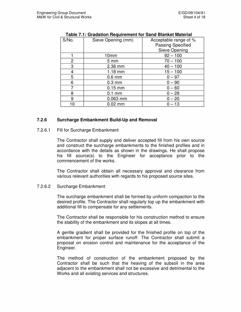
Engineering Group Document E/GD/09/104/A1 M&W for Civil & Structural Works Sheet 4 of 18
Table 7.1: Gradation Requirement for Sand Blanket Material
S/No. Sieve Opening (mm) Acceptable range of % Passing Specified
Sieve Opening
1 10mm 92 – 100
2 5 mm 70 – 100
3 2.36 mm 40 – 100
4 1.18 mm 15 – 100
5 0.6 mm 0 – 97
6 0.3 mm 0 – 90
7 0.15 mm 0 – 60
8 0.1 mm 0 – 28
9 0.063 mm 0 – 20
10 0.02 mm 0 – 13
7.2.6 Surcharge Embankment Build-Up and Removal 7.2.6.1 Fill for Surcharge Embankment The Contractor shall supply and deliver accepted fill from his own source
and construct the surcharge embankments to the finished profiles and in accordance with the details as shown in the drawings. He shall propose his fill source(s) to the Engineer for acceptance prior to the commencement of the works.
The Contractor shall obtain all necessary approval and clearance from
various relevant authorities with regards to his proposed source sites. 7.2.6.2 Surcharge Embankment The surcharge embankment shall be formed by uniform compaction to the
desired profile. The Contractor shall regularly top up the embankment with additional fill to compensate for any settlements.
The Contractor shall be responsible for his construction method to ensure
the stability of the embankment and its slopes at all times. A gentle gradient shall be provided for the finished profile on top of the
embankment for proper surface runoff. The Contractor shall submit a proposal on erosion control and maintenance for the acceptance of the Engineer.
The method of construction of the embankment proposed by the
Contractor shall be such that the heaving of the subsoil in the area adjacent to the embankment shall not be excessive and detrimental to the Works and all existing services and structures.

Engineering Group Document E/GD/09/104/A1 M&W for Civil & Structural Works Sheet 5 of 18
7.2.6.3 Instrumentation and Monitoring The Contractor shall monitor the ground condition for consolidation and
ground stability. The Contractor shall adhere to the sequence of operations for the placement of drains and instrumentation. The protection of the instruments shall consider the sequence of the construction.
7.2.6.4 Removal of Surcharge Embankment The completed embankment shall remain and be maintained at the site
with appropriate instrument monitoring for a continuous period of not less than the stipulated period given in the Contract. The Engineer shall reserve the right to increase or reduce the embankment surcharge period and order the early removal of the embankment when he deems necessary, at no additional cost to the Contract.
Upon removal of the embankment, the fill materials shall be disposed off
site to the Contractor’s own dumping ground. 7.3 SOIL IMPROVEMENT USING JET GROUTING Jet Grouting is a process of improving the ground by cutting it with high
pressure jet(s) and mixing and replacing the resulting slurry with cement grout. The Contractor shall comply with the requirements of BS EN 12716 – Execution of Special Geotechnical Works – Jet Grouting.
The Jet Grouting mentioned in this Chapter applies to mass treatment of
soil to meet the strength and stiffness criteria. If it is used for other applications, the designer shall apply relevant codes to the acceptance of Engineer.
7.3.1 Method Statement for Jet Grouting The Contractor shall submit a detailed method statement for the grouting
works. It shall include the minimum information required in BS EN12716. The method statement shall also include:
(a) the target strength and stiffness of the piles (b) ground movement monitoring plans (c) proposals for a jet grouting trial including the location and monitoring
of the trial. The method statement shall be reviewed in the light of the results of the
trial and if necessary resubmitted for the acceptance of the Engineer prior to the commencement of the main Jet Grouting works.

Engineering Group Document E/GD/09/104/A1 M&W for Civil & Structural Works Sheet 6 of 18
7.3.2 Jet Grouting Trial Before carrying out the proposed jet grouting, the Contractor shall carry
out a jet grouting trial to demonstrate the suitability of the proposed method. This shall be carried out in full accordance with the Contractor's method statement.
One minimum trial test shall be carried out at site for each soil type (based
on the DC Chapter 5 classification) to be treated. The trial jet grouting shall consist of a minimum of six overlapping columns
formed at the depth and in similar ground conditions as the proposed jet grouting.
The effectiveness of the trial grouting shall be demonstrated with a
minimum of four boreholes used to obtain cores through the full depth of the grouted block. Of the four boreholes, one shall be targeted at the centre of a pile, one at a point two third of a pile radius from the centre, and the remaining two at the overlapping areas of the piles. The cores shall be fully logged and shall be tested for strength and stiffness. A minimum of 3 samples shall be taken from top and middle and bottom of each core for strength and stiffness testing.
If TCR fails to achieve 85% or any of the strength or stiffness tests fail the
target value, the Jet Grouting trial is deemed to fail, further trial(s) with more conservative operation parameters shall be carried out.
A minimum of 3 SPT tests at the overlapping areas of the piles shall be
carried out at each borehole. The strength and stiffness test results shall be used to correlate with SPT values. The correlation shall be agreed with the Engineer, and used only as supplementary to the more direct TCR, strength and stiffness tests for the subsequent quality control.
A grid of settlement/heave monitoring points shall be established over the
trial area, at a spacing of not greater than 5m. All buildings, structures and utilities within a distance of 1.5 times the maximum depth of grouting shall also be monitored for movement. All points shall be monitored at least twice per day when drilling or grouting work is in progress.
The Contractor shall submit the results of the trial Jet Grouting to the
Engineer, together with an interpretative report assessing the results of the trial and proposing any necessary changes to his method statement.
7.3.3 Drilling and Grouting The drilling and grouting plant shall be equipped with automatic, data
loggers collection system(s) to allow the operating parameters to be checked and recorded continuously during drilling and grouting operation. All the measuring devices shall be calibrated before the start of the work, and the records of the calibration submitted to the Engineer.
Engineering Group Document E/GD/09/104/A1 M&W for Civil & Structural Works Sheet 7 of 18
Materials used as a flushing medium for drilling or as part of the grout mix shall be non-toxic and subject to the acceptance of the Engineer. Materials data sheets for each material shall be submitted to the Engineer for acceptance.
All drilling and grouting effluent shall be collected in trenches, pits or tanks
and not allowed to spread over or outside the site. Measures shall be taken to ensure that the effluent cannot enter the public drainage system. All effluent shall be removed from the site and disposed of in accordance with the regulations.
The requirement for settlement/heave monitoring shall be the same as for
the jet grouting trial. 7.3.4 Records A record sheet shall be made for every jet grout pile installed. This record
sheet shall include:
(a) reduced levels for the ground level, the top and base of the pile (b) inclination of the pile (c) operating parameters as used for the pile installation (d) details of casing size and length (e) length of drilling (f) type of flushing medium (g) duration and timing of each major activity (h) total materials used, for example, Delivery Order (i) observations on slurry return, breakdowns, interruptions during
drilling or grouting and any other relevant events The format of records shall be submitted by the Contractor to the
acceptance of Engineer prior to the commencement of works at site. At the completion of any continuous block or section of Jet Grouting, a
summary report shall be submitted to the Engineer. This report shall provide:
(a) As-built drawings showing the layout, inclination and installed depth
of each Jet Grout pile (b) The results of all site investigation carried out related to the Jet
Grouting works (c) The location and final values of all monitoring carried out during and after the Jet Grouting works (d) The results of the quality control testing carried out at site
7.3.5 Quality Control The operating parameters shall be checked and recorded continuously by
the automatic, data logger collection system(s), which shall include the following as a minimum:
Engineering Group Document E/GD/09/104/A1 M&W for Civil & Structural Works Sheet 8 of 18
(a) All fluids (pressure, flow rate) being injected at any time including air, water and grout (b) All pressure gauges in hydraulic oil lines to quantify a “specific drilling
energy” from the rig power unit. Parameters are to include torque and thrust (down).
(c) Drilling head, including rotation speed, depth, lifting speed, and mast inclination mounted on the drilling head. (d) Drill string, including borehole deviation to clearly demonstrate the borehole orientation/inclination at all depths (horizontal location and inclination)
The continuously recorded data shall be monitored by suitably qualified
personnel who shall take necessary action should any data falls below the designed working parameters.
Recorded data shall be provided to the Engineer in both hardcopy and
electronic format compatible with Microsoft Excel. The format shall be agreed upon and approved by the Engineer before commencement of the works. The recorded data shall be submitted to the Engineer within 24 hours after the completion of each Jet Grout column.
The grout mix shall be checked by measuring the specific gravity using a
mud balance. This shall be done at random, but not less than twice a day per rig.
The specific gravity and viscosity of the effluent return shall be checked
using mud balance and Marsh cone. This shall be done at least once per pile, during grouting.
The quality of the jet grout shall be confirmed by SPT tests and coring. There shall be 8 boreholes for each 1,000 cubic metres (rounded up to the
nearest whole number of boreholes) of treated soil. The boreholes shall be at the overlapping area of the piles. In each borehole, the SPT tests shall be done at the top, middle and bottom of the treated zone. SPT tests may be replaced by Cone penetration tests to the acceptance of the Engineer.
There shall be 4 numbers of coring through the full depth of the piles for
each 1,000 cubic metres (rounded up to the nearest whole number of cored holes) of treated soil. The cores shall be taken from the overlapping areas of the piles.
The cores shall not be less than 50mm in diameter. The quality of the jet
grouting shall be determined from the total core recovery (TCR) and the strength and stiffness of the recovered core. The TCR shall not be less than 85%. Where TCR is found to be less than 85%, two additional cores to the adjacent Jet Grout piles shall be carried out at no additional cost to the Authority. In the event that either of the additional coring fails to conform with the requirement, the Jet Grouting work is deemed to have failed.
Engineering Group Document E/GD/09/104/A1 M&W for Civil & Structural Works Sheet 9 of 18
A minimum of 3 samples shall be taken from top and middle and bottom
of each core for strength and stiffness testing. The selection of coring locations shall be determined by the Engineer.
The strength and stiffness shall comply with the minimum requirements
specified in the design. The cored holes shall be backfilled by cement bentonite grout. If either of the strength or stiffness test fails to achieve its target value, two additional samples in the same core shall be tested for strength and stiffness at no additional cost to the Authority. In the event that either of the additional samples fails to conform with the requirement, the Jet Grouting work is deemed to have failed.
If the jet grouting work is deemed to have failed, the Contractor shall
propose remedial measures to the Acceptance of Engineer. The designer shall re-assess the design parameters of the JGP and carry out the design checks to evaluate his original design to the acceptance of Engineer.
The quality, strength and stiffness of the JGP will have a major impact on
the overall behavior of the temporary works, especially in the case of sacrificial JGP layers. All data relating to the JGP quality tests shall be assessed by the Professional Engineer responsible for the design of temporary works. The PE shall ensure that the upper bound and lower bound values of the strength and stiffness of the as built JGP have been catered for in his original design.
The Contractor shall submit a full report on the testing results, including
his assessment of the results and any proposals for remedial work, to the Engineer.
7.3.6 Control of Ground, Building and Utility Movements The Contractor shall propose measures to control ground movements
during jet grouting works. Unless accepted otherwise by the Engineer, the following measures to
control ground movements shall be implemented, as a minimum requirement:
(a) minimise the angle of inclination of the grout monitor, as far as is practical (b) use a casing of not less than 200mm diameter during grouting (c) ensure that the lower end of the casing is no higher than 3.5m above
the lowest grouting jet during grouting (d) Pre-cut the Jet Grout column with water jetting (e) ensure that there is a free flow of effluent at all times
The empty bore above the jet grout pile shall be filled with grout during the
extraction of the grouting monitor.
Engineering Group Document E/GD/09/104/A1 M&W for Civil & Structural Works Sheet 10 of 18
The Contractor shall immediately cease jet grouting works when
settlement or heave trigger levels are exceeded at any monitoring point, or there is any visible damage to buildings or utilities, during jet grouting works. He shall not recommence Jet Grouting work until he has proposed additional measures to control the ground movements.
7.4 DEEP SOIL MIXING (DSM) DSM is a process of improving the ground by cutting a column of soils and
mixing it mechanically, using a rotating mixing tool, with cement or lime. The DSM column can be formed either by dry mixing or wet mixing method.
7.4.1 Method Statement for DSM The Contractor shall submit a detailed method statement for the DSM. It
shall include:
(a) location of each DSM column (b) column size and spacing (c) mixing method, binder and design mix to be used (d) equipment and plant to be used (e) methods used to control and measure the depth of penetration (f) operational parameters (g) mix proportion design (h) target DSM column strength and stiffness. (i) ground plans for the work (j) methods used to check verticality of DSM and control of ground movement during the installation process (k) testing for the quality of the binder and the finished column (l) methods used for collecting, transporting and disposal of the slurry, if any (m) proposals for a DSM trial including the location and monitoring of the trial.
The Method Statement shall be reviewed in the light of the trial results and
if necessary resubmitted for the acceptance of the Engineer prior to the commencement of the main DSM works.
7.4.2 DSM Trial Before the commencement of deep soil mixing works, the Contractor shall
conduct a trial to demonstrate the suitability of the proposed method. This shall be carried out in full accordance with the Contractor’s Method Statement.
The trial shall consist of a minimum of four columns formed at the depth
and in similar ground conditions as the proposed DSM. The trial shall be used to confirm the following:

Engineering Group Document E/GD/09/104/A1 M&W for Civil & Structural Works Sheet 11 of 18
(a) applicability of the operational parameters (b) type and quantity of binder to achieve the performance requirements (c) diameter of the DSM columns formed (d) properties of DSM columns (i.e. compressive strength and stiffness) (e) effect of the DSM on the soils above the treatment zone
The effectiveness of the trial shall be demonstrated with a minimum of two
boreholes used to obtain cores through full the depth of the DSM block. The boreholes shall be targeted within the midway between the center and outer surface of the columns. The cores shall be fully logged and shall be tested for strength and stiffness.
The Contractor shall take measures to avoid the reduction in
strength/stiffness of the soils between the ground level and the top of the treated zone. The boreholes used to test the treated zone shall be used to measure the strength and stiffness of the soils between ground level and the top of the treated zone to demonstrate the effectiveness of the measures.
A grid of settlement/heave monitoring points shall be established over the
trial area, at a spacing of not greater than 5m. All buildings, structures and utilities within a distance of 1.5 times the maximum depth of treatment shall also be monitored for movement. All points shall be monitored at least twice per day when DSM work is in progress.
The Contractor shall submit the results of the DSM trial to the Engineer,
together with an interpretative report assessing the results of the trial and propose any necessary changes to his method statement.
7.4.3 Installation of DSM Columns Before installation of the columns, the column positions shall be marked. The mixing materials used shall be non-toxic. The material data sheets for
each material shall be submitted to Engineer for acceptance. All drilling and grouting effluent, if any shall be collected in trenches, pits
or tanks and not allowed to spread over or outside the site. Measures shall be taken to ensure that the effluent cannot enter the public drainage system. All effluent shall be removed from the site and disposed of in accordance with the regulations.
The requirement for settlement/heave monitoring shall be the same as for
the DSM trial. 7.4.4 Records During the DSM column installation, the Contractor shall submit daily
progress reports and record sheets on the DSM works. The record on data sheets shall include:
Engineering Group Document E/GD/09/104/A1 M&W for Civil & Structural Works Sheet 12 of 18
(a) material and equipment type used (b) quantity of cement or lime used per meter DSM column (c) total quantity of cement and lime used in the day (d) operational parameters (e) length of DSM column installed (f) duration and time of the works.
Upon completion of each continuous block or section of the DSM works,
the Contractor shall submit a report to the Engineer to substantiate that the treated soil meets the specified objectives. The report shall be prepared to include but not limited to following information:
(a) as built drawings showing the layout and the length of DSM columns (b) results of all site investigation works related to the DSM works; (c) location and depth of core samples (d) location and final values of all monitoring results (e) results of the quality control testing carried out at site
7.4.5 Quality Control The Contractor shall confirm the quality of the DSM, by coring the
completed DSM columns. The location of coring shall be accepted by the Engineer. The coring shall be one cored hole per continuous block, plus one cored hole per 1,000 linear metres (rounded up to the nearest whole number of cored holes), of DSM columns.
Coring shall be done within the midway between the centre and outer
surface of the column to obtain samples for laboratory testing. The cores shall be inspected for continuity of the columns. The size of core shall be nominal diameter of at least 50 mm. Unconfined compression tests and triaxial compression tests with strain measurement shall be carried out to obtain the strength and compression stiffness of the columns.
The total core recovery of the cores shall not be less than 85%. A
minimum of four samples shall be tested for strength and stiffness, and the results shall comply with the minimum requirements specified in the design.
The Contractor shall test the strength and stiffness of those soils between
the ground surface and the treated zone after each continuous block or section of treatment is completed.
7.4.6 Control of Ground, Building and Utility Movements The Contractor shall employ appropriate equipment for the DSM works to
ensure minimum disturbance to the surrounding ground and structures. The Contractor shall protect all surrounding properties including structures and services throughout the operations.
Engineering Group Document E/GD/09/104/A1 M&W for Civil & Structural Works Sheet 13 of 18
The empty bore above the DSM column shall be filled with appropriate
grout or binder during the extraction of the grouting/mixing monitor. The Contractor shall immediately cease DSM works when the settlement
or heave trigger levels are exceeded at any monitoring point, or there is any visible damage to buildings or utilities, during DSM works. He shall not recommence DSM works until he has proposed additional measures to control the ground movements.
7.5 LIME OR CHEMICO-LIME PILES Lime or chemico-lime piling involves the formation of piles of quicklime
(unslaked lime) or chemically treated lime. The term ‘lime piles’ will be used to apply to both lime and chemico-lime piles.
7.5.1 Method Statement for Lime Piles The Contractor shall submit a detailed method statement for the lime
piling. It shall include:
(a) location and depth of each lime pile (b) pile size, length and spacing (c) equipment and plant to be used (d) methods of placing the lime and the quantities to be used (e) methods used to control and measure the depth of penetration (f) target strength and stiffness of the ground around the piles and,
where used in the design, the strength and the stiffness of the piles (g) methods used to monitor and control ground movement during and
after the installation (h) testing for the quality of the finished piles and the improvement of the surrounding ground (i) methods used for collecting, transporting and disposal of spoil (j) safety precautions to be taken while handling and installing the lime (k) proposal for a lime piling trial, including the location and monitoring of the trial.
The method statement shall be reviewed in the light of the trial results and
if necessary resubmitted to the Engineer for acceptance. 7.5.2 Lime Pile Trial Before the commencement of lime piling works, the Contractor shall
conduct a trial to demonstrate the suitability of the proposed method. This shall be carried out in full accordance with the Contractor’s method statement.
The trial shall consist of a minimum of 6 piles formed at the depth, at the
spacing and in similar ground conditions as the proposed lime piles.

Engineering Group Document E/GD/09/104/A1 M&W for Civil & Structural Works Sheet 14 of 18
The effectiveness of the trial shall be demonstrated with a minimum of four boreholes. Of the four boreholes, two shall be targeted at the middle point of the four columns, with the remaining two targeted close to one of the lime piles. The boreholes shall be used to measure the water content, undrained shear strength and stiffness of the ground in between the piles. Where the strength and stiffness of the columns are taken into account in the design, cores from at least two of the piles shall be taken to verify the strength and stiffness of the lime piles.
The Contractor shall take measures to avoid the reduction in
strength/stiffness of the soils between the ground level and the top of the treated zone. The boreholes used to test the treated zone shall also be used to measure the strength and stiffness of the soils between ground level and the top of the treated zone.
A grid of settlement/heave monitoring points shall be established over the
trial area, at a spacing of not greater than 5m. All buildings, structures and utilities within a distance of 1.5 times the maximum depth of lime piling shall also be monitored for movement. All points shall be monitored at least twice per day when lime piling work is in progress.
The Contractor shall submit the results of the lime piling trial to the
Engineer, together with an interpretative report assessing the results of the trial and proposing any necessary changes to his method statement.
7.5.3 Installation of Lime Piles Before installation of the piles, the pile positions shall be marked. The materials used shall be non-toxic. The material data sheets for the
lime shall be submitted to the Engineer for acceptance. All spoil shall be collected and removed from the site. The disposal shall
be in accordance with the regulations. The requirement for settlement/heave monitoring shall be the same as for
the lime pile trial. 7.5.4 Records During the lime pile installation, the Contractor shall submit daily progress
reports and record sheets on the lime piling works. The record sheets shall include:
(a) material and equipment used (b) quantity of lime used per meter of pile (c) operating parameters used for pile installation (d) length of lime pile installed (e) duration and timing of each major activity of the works.
Engineering Group Document E/GD/09/104/A1 M&W for Civil & Structural Works Sheet 15 of 18
Upon completion of any continuous block or section of the lime piling
works, the Contractor shall submit a report to the Engineer to substantiate that the treated soil meets the specified objectives. The report shall be prepared to include the following information:
(a) as built drawings showing the layout and the installed length of each lime pile
(b) the location and depth of investigation, sampling and testing (c) the results of all testing (d) the location and final values of all ground monitoring (e) the results of the quality control testing carried out at site
7.5.5 Quality Control The Contractor shall confirm the results of the lime piling by carrying out
soil investigation boreholes and testing. The location of the boreholes shall be accepted by the Engineer. There shall be one borehole per continuous block, plus one borehole per 1,000 linear metre depth of lime piles (boreholes rounded up to the nearest whole number). The testing shall include measurement of the water content, undrained shear strength and stiffness of the ground between selected piles. These tests shall be carried out on undisturbed samples from boreholes to the full depth of the piles. Where the strength and stiffness of the lime piles is utilized in the design, the strength and the stiffness of the selected piles shall also be verified.
All boreholes shall be backfilled by cement bentonite grout. A minimum of four undisturbed samples shall be tested for water content,
undrained shear strength and stiffness of the ground between the selected piles. The results shall comply with the minimum requirements specified in the design.
7.5.6 Control of Ground, Building and Utility Movements The Contractor shall employ appropriate equipment for the lime piling
works to ensure minimum disturbance to the surrounding ground and structures. The Contractor shall protect all surrounding properties including structures and services throughout operations.
Predrilling shall be used, where appropriate, to avoid heave during lime
pile installation. The empty bore above the lime pile shall be filled with appropriate filler.
The Contractor shall immediately cease lime piling works when the
settlement or heave exceed the trigger levels at any monitoring point, or there is any visible damage to buildings or utilities, during lime piling works. He shall not recommence lime piling works until he has proposed additional measures acceptable to the Engineer to control the ground movements.
Engineering Group Document E/GD/09/104/A1 M&W for Civil & Structural Works Sheet 16 of 18
7.6 DYNAMIC COMPACTION Dynamic compaction involves high-energy impact using a heavy weight
dropped from height. 7.6.1 Method Statement for Dynamic Compaction The Contractor shall submit a detailed method statement for the dynamic
compaction. The method statement shall include:
(a) drawings indicating the location of each tamper drop (b) shape and weight of tamper (c) height of tamper drop for each pass (d) planned number of blows per pass and the number of passes (e) capacity and height of equipment (f) methods used to monitor and control ground movement and heave during and after compaction (g) proposal for a dynamic compaction trial, including the location and monitoring of the trial (h) safety precautions to be taken while carrying out dynamic
compaction (i) proposal for testing as part of the quality control measures to ensure good quality of dynamic compaction
The method statement shall be reviewed in the light of the trial results and
if necessary resubmitted to the Engineer for acceptance. 7.6.2 Dynamic Compaction Trial Before commencement of dynamic compaction works, the Contractor shall
conduct a trial to demonstrate the suitability of the proposed method. The field trial shall also be used to determine the optimum parameters for grid spacing, energy level of blows, number of blows per pass, number of passes, etc.
The field trial shall be carried out in accordance with the Contractor’s
method statement. A trial area of minimum 40m x 40m in similar ground conditions shall be
used. The field trial shall include the following field measurements and in-situ
tests:
(a) crater depth and diameter (b) average ground settlement after each complete pass; (c) in-situ tests including in-situ density tests, standard penetration tests
(SPT), cone penetration tests (CPT) and pressuremeter tests (PMT) for soil before and after treatment
Engineering Group Document E/GD/09/104/A1 M&W for Civil & Structural Works Sheet 17 of 18
(d) pore water pressure monitoring by piezometer during and after compaction
(e) lateral movement monitoring of adjacent ground by inclinometers at 10m interval up to 50m away from the tamping area during and after compaction, and
(f) Ground vibration monitoring of adjacent ground at 10m interval up to 50m away from the tamping area.
7.6.3 Conducting Dynamic Compaction Before execution of dynamic compaction, the compaction positions shall
be marked. The Contractor shall provide a working platform made up of a layer of
granular fill of a minimum 1m thick for working. A final, low energy pass (ironing pass) shall be employed at least once
over the whole area treated with dynamic compaction. For the ironing pass a weight of square footprint shall be used and each print shall overlap at least 0.25 times the size of the adjacent print. If the top 1m of the material is still not compacted properly after the ironing pass, standard surface compaction equipment shall be used for densification.
The sequence of the dynamic compaction shall be planned in such a way
to ensure that no area can be easily missed without treatment. Blow nos., pass nos. for each print and crater depth and diameter shall be recorded for each drop and countersigned by the Engineer’s representative.
The Contractor shall minimize the vibration on adjacent structures and
utilities. 7.6.4 Records The Contractor shall submit daily progress reports and record sheets on
the works. The record sheets shall include:
(a) operational parameters (b) duration and time of the works
Within one month upon completion of the dynamic compaction works, the
Contractor shall submit a report to the Engineer. The report shall include:
(a) as-built drawings showing the layout of the area treated with dynamic compaction (b) results of pre and post treatment boreholes and in-situ tests (c) ground monitoring results
7.6.5 Quality Control The following quality control measures shall be adopted:
Engineering Group Document E/GD/09/104/A1 M&W for Civil & Structural Works Sheet 18 of 18
(a) two numbers each of in-situ density tests, SPT, CPT, and PMT at
every 200m interval. (b) four samples from two cores at every 200m interval from different
depths for density tests. The size of core shall be not less than 50 mm in diameter.
(c) settlement monitoring of at every 25m interval.
7.6.6 Control of Ground, Building and Utility Movements and Vibration The Contractor shall employ appropriate equipment for the dynamic
compaction works to ensure minimum disturbance to the surrounding ground and structures. The Contractor shall protect all surrounding properties including structures and services throughout operations. Additional measures, such as cut-off trenches for vibration shall be utilised, where necessary.
The Contractor shall immediately cease dynamic compaction works when
the settlement, heave or vibration exceeds the trigger levels at any monitoring point, or there is any visible damage to buildings or utilities, during the dynamic compaction works. He shall not recommence the dynamic compaction works until he has proposed additional measures acceptable to the Engineer to control the ground movements.

Engineering Group Document E/GD/09/104/A1 M&W for Civil & Structural Works Sheet 1 of 6
CHAPTER 8
TEMPORARY WORKS 8.1 GENERAL Temporary Works are all construction works that are not part of the
Permanent Works but are required in order to complete the Permanent Works.
The Contractor shall design, provide, maintain and remove on completion
all Temporary Works as may be necessary for the execution of the Works, unless otherwise stated in the Contract Documents.
All Temporary Works shall only commence once the method statement,
drawings and calculations have been accepted by the Engineer. The method statement for Temporary Works shall include methods of removal of the Temporary Works. Loading and/or removal of the Temporary Works shall not be carried out without the acceptance of the Engineer.
All Temporary Works shall be to the same standard as the Permanent
Works, unless otherwise accepted by the Engineer. All materials used as load-carrying components shall be new material
conforming to the relevant Singapore or British Standards. Where re-used materials are applied, the quality of the material shall be up to the standard which tally with the design assumptions.
Standard headroom under temporary structures shall be 5.4m over
highways, and 2.3m over footpaths. Any material that represents a fire hazard or could emit noxious fumes will
be rejected for use in the Temporary Works and shall be removed from site immediately.
8.2 DESIGN AND SUPERVISION OF TEMPORARY WORKS The Contractor shall appoint a Professional Engineer (PE) with relevant
experiences subject to the acceptance of the Engineer. The PE shall certify the design of the Temporary Works. He shall also certify that the Temporary Works have been constructed to the design and that they are safe to load and that the Temporary Works can be dismantled.
The PE shall be responsible for the Temporary Works, including any
intermediate inspections that shall be carried out if the Works are in place for more than 1 week or if there has been a change in loading conditions or after any adverse weather conditions. The Contractor shall submit a schedule of inspection for the Temporary Works by the PE.

Engineering Group Document E/GD/09/104/A1 M&W for Civil & Structural Works Sheet 2 of 6
8.3 FALSEWORK Falsework shall be protected from accidental impact such as passing
vehicles. 8.4 SCAFFOLDING AND STAGING Timber scaffolding and wooden ladders shall not be used. Erection of all scaffolding and staging shall be supervised by a registered
scaffold erector in compliance with the Factories Act. Scaffold boards shall be of sound timber throughout and shall be
periodically inspected and all boards that are found to be damaged or showing signs of deterioration shall be replaced by suitable boards.
Scaffold runs and platforms shall be close boarded with boards of a
thickness such that unacceptable deflections shall not occur. All access shall be via safe close-boarded walkways.
Protective safety railing shall be provided on all external edges. At a
minimum, the railing shall have toe boarding, a middle rail and top hand railing.
Ladders between platforms and scaffold runs at different levels shall be
securely fixed in place, and rigidly constructed. The ladder rungs shall have a non slip surface with centres not greater than 300mm.
Scaffolding shall undergo a weekly check by a registered scaffold erector,
who shall record his inspection on a site register, including the date of his inspection, his name, any findings and any PE approved modifications that he has carried out.
Any defect found during an inspection will be put right immediately. If this
is not possible and the scaffold is not safe it will be taken out of use immediately by placing a barrier and warning sign at each access point.
Temporary access stairways and walkways shall comply with BS5395:
Part 1, particularly with respect to clear minimum headroom and clearance, both vertically and perpendicular to the plane of the stairs.
8.5 TEMPORARY DECKING For expressways and semi-expressways, the temporary decking shall be
designed with an asphalt premix top providing a skid resistance value in excess of 55 as defined in Road Note No. 27 of the United Kingdom, Road Research Laboratory.

Engineering Group Document E/GD/09/104/A1 M&W for Civil & Structural Works Sheet 3 of 6
For temporary deck panels used on all other roads, the exposed surface of the panels shall be of a chequer patterned surface (with protrusion height in excess of 2mm) and coated with anti-skid coating. The anti-skid coating shall provide a skid resistance value in excess of 45 as defined in Road Note No. 27 of the United Kingdom, Road Research Laboratory.
All physical testing shall be carried out using the Portable Skid Resistance
Tester and according to the operating procedure defined in Road Note No. 27 of the United Kingdom, Road Research Laboratory.
The drainage of the temporary deck shall be such that all surface water
shall be retained within the plan area of the temporary deck and be efficiently discharged through connections to the existing drainage system, to the acceptance of the Engineer.
The finished level, falls and camber of the temporary deck shall be in
accordance with the existing roadway unless otherwise accepted by the Engineer. Walkways drained to the acceptance of the Engineer shall be provided to replace existing walkways which are overlapped by the temporary decking.
All preparation, re-coating and repair to the temporary deck panels with
anti-skid coating shall be carried out off-site, except where in-situ re-coating is permitted.
Before installation of new temporary deck with anti-skid coating, the following shall be carried out:
a) Physical testing shall be carried out on two deck panels or 5% of the
total number of deck panels, whichever is greater, to demonstrate that the required skid resistance value is provided.
b) A proposed maintenance programme/schedule and method statement shall be submitted to the Engineer for acceptance. The contractor shall conduct a weekly visual inspection of the temporary
decking with anti-skid coating in the presence of the Engineer’s representative. At the end of every month, a report containing the following shall be submitted (within 1 week of the last inspection) to the Engineer for acceptance and records.
a) Photographs and descriptive appraisal of temporary decking physical
condition (e.g. report any defects/damages). b) Descriptive appraisal of the condition of the surface drainage system. c) Descriptive appraisal of the condition of the anti-skid coating and
chequered surface. d) Descriptive appraisal of the condition of the structural integrity
(necessary only once every 3 reports) e) Remedial actions taken (if any)
Engineering Group Document E/GD/09/104/A1 M&W for Civil & Structural Works Sheet 4 of 6
Following every visual inspection, all damaged temporary deck panels with anti-skid coating, as indicated or marked by the Engineer, shall be replaced. The replacement shall be completed within a week.
Physical testing of the performance of the temporary decking with anti-skid
coating shall be conducted in-situ every three months unless otherwise directed by the Engineer.
Test points for the insitu physical testing shall be spaced, not more than
5m, along the 2 wheel paths of vehicles for each traffic lane of the carriageway and shall not be within 0.2m from the edge or joint of the temporary deck panels. Prior to testing, the proposed layout of the test points shall be accepted by the Engineer.
Each test point shall be tested to obtain a minimum of three readings and
the average of the readings shall be representative of the skid resistance value for that test point. Remedial work shall be carried out immediately when the skid resistance value falls below 45.
Following every physical testing, a test report containing the following
information shall be submitted to the Engineer for acceptance and records within 1 week.
a) Date and Time of Test b) Location of test c) Age of coating or Date of previous application d) Estimated traffic volume per day e) Test results (Skid Resistance Value) f) Remedial actions taken (if any)
The remedial work on the temporary deck panels with anti-skid coating
may be either one of the following, as directed by the Engineer.
a) In-situ reapplication of the anti-skid coating to the temporary deck panels in the area surrounding the failed test point
b) Replacement of the temporary deck panels surrounding the failed test point with newly coated ones
c) The remedial works shall cover a minimum area of a full traffic lane width by 5m longitudinally (i.e. 2.5m long from either side of the test point).
Spare temporary deck panels ready for use and in an amount not less
than 10% of the total numbers of temporary deck panels used, shall be kept in stock at all times.
Replacement for the entire temporary decking with newly coated
temporary deck panels shall be carried out sequentially (lane by lane) at every 12 months. The interval may be:

Engineering Group Document E/GD/09/104/A1 M&W for Civil & Structural Works Sheet 5 of 6
a) Lengthened should the Engineer deem that there has been proper maintenance carried out and that the performance of the temporary decking consistently meets the minimum requirements.
b) Shortened should the Engineer deem that the overall performance and condition of the temporary decking is deficient and warrants a replacement.
The replacement shall be completed within 3 weeks. In addition, physical
testing shall be conducted on the temporary decking before and after the replacement.
8.6 GROUND ANCHORS Where the Contractor proposes to use ground anchors as part of his
Temporary Works, he shall as part of his method statement submit to the Engineer a detailed specification. The ground anchors shall be removed as far as practicable to the acceptance of the Engineer.
8.7 SHEET PILING Sheet piles shall be of interlocking and weldable type. Each pile shall be in one length throughout but where required may be
extended by welding on an additional length subject to the acceptance of the Engineer. All welding shall be done by a certified welder.
Purpose made sheet piles shall be driven to form corners and junctions.
The clutches shall be of a type which shall prevent unacceptable ingress of water into the excavations and shall be of a strength and rigidity such that distortion during handling, pitching and driving shall not occur.
The sheet piles shall be driven vertically on the lines and to the
dimensions and tolerances shown on the Temporary Works Drawings and shall be pitched in panels.
Holes in the piling for ties and attachment of waling etc., shall be drilled
after driving. Burning of holes shall not be carried out without the acceptance of the Engineer.
8.8 STRUTS & WALINGS The packing between the temporary walls and walings shall be concrete or
steel. All struts shall be preloaded to at least 50% of the design load, unless otherwise accepted by the Engineer.

Engineering Group Document E/GD/09/104/A1 M&W for Civil & Structural Works Sheet 6 of 6
8.9 DEWATERING The Contractor shall install, operate and maintain all necessary pumping
plant and drainage facilities and remove all accumulated silt and debris as required for proper execution of the works.
Groundwater control and drawdown shall be to the Engineer’s acceptance
and in line with the relevant method statement. Where settlement due to consolidation is predicted to cause unacceptable
damage to structures or utilities, the Contractor shall implement measures to prevent such damage.
8.10 REMOVAL OF TEMPORARY WORKS Grouting of voids resulting from the extraction of Temporary Works shall
be carried out immediately with the extraction. The method of extraction or removal shall be such that there is no risk of
damage to the Permanent Works. The Contractor shall follow the design construction sequence, and before
removing any strut the Contractor shall have demonstrated to the satisfaction of the Engineer that there is sufficient support to the retained ground to avoid failure or excessive movement.

Engineering Group Document E/GD/09/104/A1 M&W for Civil & Structural Works Sheet 1 of 39
CHAPTER 9
INSTRUMENTATION AND MONITORING 9.1 OBJECTIVES The objectives of the instrumentation and monitoring of the Works are to
determine ground movements and the effects on existing structures, services and utilities in a form that will allow direct comparison with performance criteria and design expectations.
9.2 SUBMISSIONS The Contractor shall submit detailed method statements for the installation
of all instruments for the acceptance of the Engineer at least 21 days prior to commencement of installations. These method statements shall include the following for each instrument:-
(a) Detailed drawings showing the instrument types, precise location and
depth. (b) Manufacturer's specifications and recommendations for installation,
maintenance and calibration. (c) Details of equipment, methods and material (including samples) used
in drilling works for instrument installation. (d) Sequence of assembly and connection details. (e) Details of any backfill and grout mixes for backfill. (f) Details of monitoring arrangements and verification procedures. (g) Methods of taking readings for maintaining consistency. (h) A programme of installation related to the main construction activities. (i) Any other relevant information.
All readings taken shall be in strict accordance with the approved method statements in order to ensure and maintain consistency.
The Engineer shall be given at least 48 hours notice of the intention to
install any instrument. All instruments shall be installed not less than four weeks prior to the construction activity or area of works to which they relate unless otherwise accepted by the Engineer.
Fully detailed drawings of the completed installation shall be provided
together with descriptions of the principal features, mode of operation, the measuring range and the degrees of accuracy of the equipment.
The Contractor shall provide calculations to convert raw output to
processed data for all instrumentation. A sample calculation with appropriate data listings shall be provided.

Engineering Group Document E/GD/09/104/A1 M&W for Civil & Structural Works Sheet 2 of 39
9.3 INSTRUMENTATION PERSONNEL AND RESOURCES The Contractor shall provide sufficient resources to ensure that the
instrumentation and monitoring works are completed to the satisfaction of the Engineer. The contractor shall submit a detailed schedule of manpower and equipment resources to be employed for the instrumentation works one month prior to the commencement of the works or other such time agreed with the Engineer.
The Contractor shall provide at least one Instrumentation Engineer who
will be subjected to the acceptance of the Engineer. Any replacement of the Instrumentation Engineer shall have a hand-over period of at least one month. The Instrumentation Engineer shall co-ordinate all instrumentation work including the production of method statements, calibration, installation, data acquisition, data verification, data processing, data presentation and reporting.
The Instrumentation Engineer shall possess a degree from a recognised
university with at least three (3) years of relevant experience in the installation and monitoring of instruments, data base management and interpretation of instrumentation results.
All other personnel involved in installation, testing, calibration, reading and
maintenance of the instruments shall be qualified and experienced in the field of instrumentation, structural monitoring, geotechnical monitoring and survey, as appropriate. Evidence of experience shall be provided and shall include CVs and records of previous works undertaken.
9.4 INSTRUMENTS AND MONITORING SYSTEMS Pneumatic piezometers shall not be used in the works. In addition, all instruments shall have proven track records of reliable
performance used under similar conditions for similar duration to the acceptance of the Engineer.
All instruments and measuring devices shall be manufactured by
companies with proven experience in the field of construction or geotechnical instrumentation, as appropriate. The accuracy and dependability of the equipment shall not be affected by changes in temperature, humidity, stray currents or contaminants that may be encountered. Calibration certificates shall be provided by an accredited testing company.
Maintenance, inspection and calibration schedules for all instruments,
including read out and data loggers shall be submitted prior to installation or use of the instrumentation for the acceptance of the Engineer.

Engineering Group Document E/GD/09/104/A1 M&W for Civil & Structural Works Sheet 3 of 39
9.5 INSTALLATION AND MAINTENANCE OF INSTRUMENTS All equipment shall be installed and tested in accordance with the
manufacturer’s instructions or recommendations. Testing shall be undertaken as necessary to ensure satisfactory functioning of the equipment at each stage of the installation. Instruments found to be malfunctioning at any time shall be reported to the Engineer immediately and replaced at the earliest opportunity, but in any case no later than 24 hours from the time of the fault being identified.
All instruments shall be securely fixed and their terminations including any
attendant wiring and terminal panels, shall be adequately protected against physical damage, adverse climatic conditions and ingress of water and dirt.
All instruments shall be tagged using aluminium rigid nameplates minimum
size 2500 mm2, SWG 24 or similar to the acceptance of the Engineer identifying the following:-
(a) Project title and Contract No. (b) Equipment reference number (c) A contact name (d) A contact telephone number.
Drawings showing the minimum protection details for inclinometers,
piezometers, extensometers and settlement points are given in Appendix 9.1. The Contractor shall develop protection systems for other instruments. These protection systems shall provide a similar or better level of protection as those shown in Appendix 9.1. The drawings showing the proposed protection systems shall be submitted to the Engineer for acceptance. Each instrument shall be protected using the accepted protection system.
Periodic checks of all instruments in accordance with the approved
schedule shall be carried out to confirm the validity of calibration of equipment in accordance with the manufacturer’s instructions and any adjustments that are found necessary shall be made. Records shall be kept of checks, errors measured and any adjustment undertaken.
Copies of all certification shall be held on site and made available for the
Engineer’s inspection when required. All instruments or readout boxes shall be accessible for taking readings
with the specified accuracy of the instrumentation maintained. Measures shall be taken to ensure that electrical instrumentation is not
adversely affected by other temporary or permanent electrical services and equipment, and does not affect any other services, activities or equipment within or adjacent to the Works.

Engineering Group Document E/GD/09/104/A1 M&W for Civil & Structural Works Sheet 4 of 39
9.6 INSTRUMENT READING AND RECORDS The Contractor shall establish a logical reference system for all the
instrumentation equipment prior to installation and to the satisfaction of the Engineer so that records for any particular location can easily be recovered for interpretation or review.
All instruments shall have their readings taken as soon as possible after
installation and at least once per day for a period of two weeks thereafter. Where instruments appear not to have stabilised, for example exhibiting a continued drift in the readings, the cause shall be identified and the fault rectified and a new set of readings provided. When all instruments are showing consistent results for a period of 1 week, readings shall be averaged to provide a datum reading. No works that could affect the readings of the instruments shall be allowed to proceed before a datum reading is agreed with the Engineer.
The frequency of readings shall be at least one reading per month from
the establishment of datum readings up to the end of the Defect Liability Period. Depending upon the stage of the works, the frequency of reading will vary between one month, daily or in some cases, continuous logging, to the acceptance of the Engineer.
When taking instrumentation readings, the following information shall also
be recorded:-
(a) All site conditions that may affect the results shall be recorded, e.g., temperature and humidity readings.
(b) Instrument type, location reference, datum and time of reading. (c) Personnel carrying out the readings and measuring instrument or
readout unit used with its respective serial numbers to be provided where applicable.
(d) Observations of unusual conditions that could influence the instrumentation or the structure.
Instrument readings shall be recorded digitally for subsequent analysis by
computer. Backup copies shall be taken on a daily basis. Corrections shall be made for temperature difference or other factors, as appropriate but uncorrected data shall also be available. Plots of deformation, stress, raw data readings against time shall be produced together with plots of temperature and humidity when relevant.
The same measuring devices shall be used for the same instruments
throughout the monitoring programme. If this becomes impractical, new datum readings shall be taken immediately with a replacement measuring device which shall be used for the future readings.
All instruments shall be removed and installations shall be made good to
the satisfaction of the Engineer upon completion of the monitoring or at other such times if accepted by the Engineer.

Engineering Group Document E/GD/09/104/A1 M&W for Civil & Structural Works Sheet 5 of 39
9.7 RECORDING EQUIPMENT AND ANCILLARIES 9.7.1 Instrumentation Cabling All cables used in enclosed areas shall be low-smoke zero halon cables. Cabling and tubing shall be provided with sufficient slack to accommodate
potential ground movement. Cabling for the instrumentation shall be neatly and securely fixed to
appropriate cable trays, which in turn shall be securely fixed to the structure.
Cabling and connectors for instrumentation shall be of robust and water
resistant construction, and shall be corrosion resistant. Any non-metallic items shall be extinguishable in the event of fire and emit no toxic fumes.
Each cable shall be tagged at least at the instrument end connection and
at the logger connection. A schedule shall be maintained showing all cables and their respective connections.
9.7.2 Terminal Boxes for Remote Readout Terminal boxes shall collect the cabling from the various remotely read
instruments and from local junction boxes, so that monitoring can be conveniently carried out from a single position close to an instrumented section.
Terminal boxes shall be positioned for ease of access and shall be
protected from damage. The terminal and junction boxes shall be of robust water-resistant metal
construction. The boxes shall have lockable sealed doors. All cable entries to the boxes shall be through watertight seals.
9.7.3 Remote Readout Facilities All instruments with electrical sensors shall be capable of being read
remotely using portable readout units connected via the terminal boxes. Readout units shall be supplied together with leads for plugging into the measuring device and terminal boxes.
Readout units shall have facilities for recording monitoring data onto a
suitable medium for subsequent downloading to a computer for processing.
For critical instruments that require real time monitoring, modem link and
connection for direct computer link shall be made to the Engineer's site office.
Engineering Group Document E/GD/09/104/A1 M&W for Civil & Structural Works Sheet 6 of 39
9.7.4 Data Loggers Data loggers shall collect the cabling from the various remotely read
instruments and from junction or terminal boxes. Data loggers shall be reliable and compatible with the instruments and
have back-up power facilities. The reliability and compatibility of the logger shall be proven prior to installation, by demonstration and records of previous works.
All data loggers shall be connected to electrical mains by a flex outlet
without switches. Plug sockets shall not be used. Data loggers shall be:-
(a) Positioned for ease of access. (b) Programmable to log data at any specified interval, including real-time. (c) Capable of storing data for 14 days. (d) Easily connected to a portable computer directly by cables or by
modem link. (e) Unaffected by external electromagnetic influences, and shall not affect
other electrical equipment. (f) Insulated from rain and dust. (g) Fused against electrical power surges. (h) Capable of automatic shut down in the event of overheating or short-
circuiting. 9.8 SETTLEMENT POINTS Detailed requirements for precise levelling systems are given under
Chapter 3, Survey and Setting Out. Ground and building settlement shall be monitored by precise levelling.
The details of settlement markers, levelling points and studs shall be submitted to the Engineer for acceptance.
9.9 DEEP LEVELLING DATUMS Deep levelling datums, where installed to provide a reference for
measurement of ground levels in areas of soft and compressible ground, shall be fixed into deeper firmer ground and isolated from soft and compressible overlying strata.
A deep levelling datum shall comprise a 25mm galvanised steel rod cast
into a 250mm diameter grout filled steel casing positioned within a 300mm diameter steel casing. The annulus between the two casings shall be filled with grease. The top of the 25mm steel rod shall be carefully domed and centre punched.

Engineering Group Document E/GD/09/104/A1 M&W for Civil & Structural Works Sheet 7 of 39
The 300mm diameter casing shall be installed not less than 300 mm into firm ground. The 250mm diameter casing shall be driven not less than 1500mm beneath the 300mm casing.
The top of the deep levelling datum shall be protected by a manhole cover
and a surface protection barrier. 9.10 ELECTROLEVEL BEAMS The electrolevel beams should be proposed by a recognised
instrumentation manufacturer, subject to the acceptance of the Engineer, together with supporting evidence on past performance of the electrolevel beams. The electrolevel beams should be able to provide readings at appropriate time intervals from real time to daily depending on the usage.
9.10.1 System Requirements The electrolevel beams shall meet the following requirements:-
(a) The entire system shall have an accuracy of 2 seconds of arc or better
with a measuring range between ± 9 degrees. (b) The system shall not be affected by radio frequency. (c) Temperature determination at all electrolevels shall be accurate to 1oC. (d) Length of beam shall not exceed 3 m unless agreed with the Engineer. (e) All electrolevels and beams shall be uniquely calibrated against
rotation and temperature by a procedure that accurately defines the working range, accuracy, sensitivity and resolution. This information shall be shown on a calibration certificate clearly identifying the electrolevel sensor unit.
(f) All software used for the display, analysis and interpretation of the readings shall be acceptable to the Engineer. Methods and values used in raw output conversion and correction for temperature and tilt shall be submitted.
9.10.2 Installation The installation of an electrolevel system shall be in accordance with the
following requirements:- (a) Fixing of the electrolevel beams to the structure shall be by screw or
approved epoxy resin. Rivets shall not be used. Beam mounting points shall be firmly attached to the structure, such that the beam operates freely in the desired axis of measurement.
(b) Beams shall be protected against the effects of rapid temperature change and thermal expansion / contraction of the beam or mounting fittings shall not affect accuracy of the tilt reading.
(c) Mounted beams shall be aligned to within 1 degree of each consecutive beam and the desired axis of measurement on the structure.
Engineering Group Document E/GD/09/104/A1 M&W for Civil & Structural Works Sheet 8 of 39
(d) Damage to any structure by installation of mounting fittings or cable runs shall be minimised and only permitted with the prior acceptance of the Engineer.
(e) Beams shall be protected from disturbance from hanging wires, birds etc. Prominent warning signs shall be placed by the beams to avoid misuse.
(f) All beams/electrolevel sensor units shall be clearly marked with identifying codes and direction of tilt.
A calibration check and directional check shall be carried out for each
beam installed. This shall involve a device able to move one end of the beam by controlled increments of 2, 4, 8, 10, and 15 millimetres. This calibration shall be performed twice for the beam to check reproducibility of results. The result of the calibration check shall be provided, clearly marked with the beam / sensor unit identifying code, for attachment to the calibration certificate.
The Contractor shall be responsible for maintaining the beams for the
required period of monitoring, and shall be responsible for the removal of the beams and making good any damage to the structures.
9.11 INCLINOMETERS 9.11.1 General Inclinometers shall take the form of an access tube with four key ways (in
pairs at right angles) which shall be grouted in a borehole. The orientation of the key ways shall be such that they are parallel and perpendicular to the orientation of any tunnel, excavation or wall or otherwise as accepted by the Engineer.
When taking readings the inclinometer probe shall be inserted in the tube
and shall travel along the whole length of the tube with its wheels engaged in each pair of the key ways in turn to obtain deformation measurements in both directions. The probe wheels shall be compatible with the key ways. Changes in inclination shall be displayed on a portable readout unit.
A suitable means of measuring the position of the probe down the
borehole to an accuracy of ±10 mm from a reference point at the top of the borehole shall be provided.
Both the probe and the portable readout units shall be calibrated at
intervals recommended by the manufacturer. The inclinometer tubing shall have an outer diameter of 85 mm and shall
be pre-grouted into a minimum 125 mm diameter borehole or a steel duct of at least 150mm cast into any pile or wall.

Engineering Group Document E/GD/09/104/A1 M&W for Civil & Structural Works Sheet 9 of 39
The inclinometer tubing shall be of uniform section and be free of twist in
manufacture and shall not be twisted during installation. The tubing shall be provided with appropriate couplings for joining tube lengths to the required borehole length. The base of the tube shall be capped. Cap and coupling joints shall be adequately fixed and sealed so that the tube is grout and dirt tight. The grooves shall be consistent in cross section. The tubing material shall be ABS plastic unless otherwise accepted by the Engineer.
The joined and sealed tubing shall be concurrently filled with clean water while being lowered into the borehole and the annulus grouted using a bentonite/cement grout tremied to the bottom of the hole. The tubing shall be held in place at the bottom until the grout sets. The tubing shall not be held down with weights attached to the top.
Immediately following installation a spiral and inclination check shall be
carried out. Corrections required to data readings shall be determined and applied.
During earthworks operations the inclinometer tubes shall be extended in
lengths and ahead of the fill to a manner accepted by the Engineer. At the final ground level the inclinometer tubing shall be fitted with a
removable cap protected by a manhole cover and surface protection barrier.
9.11.2 Electrolevel Inclinometers (Remotely Read) The inclinometer shall consist of a string of biaxially placed electrolevels
located in a slotted plastic inclinometer. Each electrolevel shall consist of waterproof sensors remotely monitored
using a computer data logging system. The resolution of the electrolevel shall be 2 seconds of arc or better and
the measuring range shall be at least ± 9 degrees. The operating
temperature range shall be at least 0°C to +50°C. Calibration certificates for each electrolevel showing calibration for both tilt
and temperature shall be provided. Both calibrations shall fully characterise the electrolevel output response over both the specified tilt and the operating temperature range. Sample calculations to translate output to movement shall be provided.
The electrolevels shall be installed at spacings not greater than 3 m and
shall be connected with a rigid rod or beam to give a fixed gauge length. At the end of the sensor and the gauge extension a spring loaded wheel assembly shall be fitted. Sensors mounted on sleds will not be acceptable.
Engineering Group Document E/GD/09/104/A1 M&W for Civil & Structural Works Sheet 10 of 39
Stability and gain of the reading system shall be checked at weekly intervals by means of three “dummy” electrolevels using precise resistors.
9.11.3 Inclinometers (Manually Read) A mechanical pulley shall be used for taking all readings The datum readings should be established using at least 2 probes and
shall be submitted together with the serial numbers of the probes. All subsequent readings shall only be taken using probes with which the
datum readings have already been established. Calibration certificates for each inclinometer probe shall be provided to the
Engineer.
The system accuracy shall be ± 6 mm per 25 m of casing or better. The stability of the reading system shall be checked at weekly intervals
through the use of checksum calculations. The inclinometer and logging system shall be capable of recording
movements in both directions (i.e. biaxial). The probe used shall have the following:-
(a) A wheel base of 500mm or greater.
(b) A measurement range of ± 35 degrees or greater from vertical. (c) A resolution of 0.02mm or better per 500mm with a repeatability of
±0.1%. (d) A minimum radius curve for retrieval of 2.2m or less.
(e) A working temperature range of at least 0°C to +50°C. (f) A construction (externally) of stainless steel.
Once the probe is introduced into the inclinometer and prior to the
commencement of readings, the probe shall be allowed the appropriate time for its temperature to stabilise.
9.12 MAGNETIC EXTENSOMETERS Magnetic extensometers employed in the Works shall consist of a series of
magnetic rings (“spider magnets”) fixed into a maximum 150mm diameter borehole with a plastic tubing allowing access to the magnetic points for the measurement of settlement.
The prongs on the magnetic rings shall be capable of extending beyond
the circumference of the borehole into the surrounding soil. The complete downhole assembly shall be grouted in place ensuring that
the access tube and magnets remain undisturbed during grouting
Engineering Group Document E/GD/09/104/A1 M&W for Civil & Structural Works Sheet 11 of 39
operations. The access tube shall be capped to prevent ingress of ground water.
The magnetic rings shall be housed in splay PVC holders suited to the
ground into which they shall be installed to the acceptance of the Engineer.
When the tubing is anchored in stable ground, a datum magnetic ring shall
be set at its base. If the bottom of the tubing is not in stable ground, the depths of the magnets shall be referenced to a level survey point at the top of the tubing which shall be surveyed by precise levelling before readings are taken.
The magnetic rings shall be installed at the depths accepted by the
Engineer or at maximum 3m intervals. The reading system shall be reliable and require minimal maintenance
over the required monitoring period. Thermal or other influences shall be negligible.
The system shall have an accuracy of ±1.0mm. 9.13 ROD EXTENSOMETERS Rod extensometers shall be able to measure relative movements of both
elongation and reduction in the length between the anchor and the reference collar to the acceptance of the Engineer.
A range adjustment device fitted at the reference collar shall extend the
reading range beyond that of the measurement device. No more than six rods shall be installed in a single hole with each rod of a
different length so that displacements at various borehole depths may be recorded.
Where more than six rods are required another borehole shall be prepared
as close as possible to the initial hole and rods set at alternate depths in each hole.
Each rod shall be individually isolated by its own plastic sleeve and the
complete assembly shall be grouted in place fixing the anchors to the ground but allowing free movement of each rod within its sleeve.
A single reference housing shall receive all of the rods from a drill hole and
provide protection to the reference head.
Engineering Group Document E/GD/09/104/A1 M&W for Civil & Structural Works Sheet 12 of 39
A level survey point shall be fixed to the top of the reference head of the
extensometer to allow precise levelling back to a datum. Rods shall be fabricated from stainless steel or fibreglass. Anchor points shall have extendable prongs or be cadmium plated
deformed mild steel bar of 22mm diameter and 500mm long. 9.14 TAPE EXTENSOMETER A tape extensometer shall comprise a steel tape, portable measuring
instrument with metric dial calliper and a pair of anchor clips. Anchors shall be located and fixed in a manner acceptable to the
Engineer.
The tape extensometer shall be capable of being read to ±0.15 mm, and
have a range of 20 m. A repeatability of reading to ±0.15 mm shall be demonstrated prior to use.
Measurements shall be taken by connecting the tape hook to the pertinent
eyebolt and the tape stretched across to the next bolt. The tension of the tape shall be adjusted and the tape and calliper readings taken.
A minimum of two tape extensometers is to be provided at the
commencement of work and these are to be calibrated against each other, so that in the event of damage to one tape, accuracy is not compromised.
9.15 VIBRATING WIRE PIEZOMETERS The type of tip shall be chosen to suit the expected maximum groundwater
pressure and the characteristics of the surrounding ground. The combined accuracy of instrument and readout device shall be within
±1.0 % of the true pressure. 9.15.1 Installation in Boreholes Drilled from the Surface All piezometers shall be tested before installation by submergence in still
clean water to a series of depths appropriate to the anticipated pressure range of operation in order to verify the calibration and accuracy of the instrument.
The tip of each piezometer shall be air free and the porous stone of the tip
shall be fully saturated by submergence in clean de-aired water for a period of at least 24 hours prior to installation. Complete de-airing of the porous stone shall be confirmed by periodic weighing.
Engineering Group Document E/GD/09/104/A1 M&W for Civil & Structural Works Sheet 13 of 39
Each piezometer shall be installed in a separate borehole of 100mm nominal diameter unless otherwise accepted by the Engineer. The complete installation shall be carried out as soon as practicable, and no later than 24 hours, after drilling to minimise the amount of deterioration or alteration of the ground at the location of the piezometer tip.
Drilling to the required depth shall be carried out without the use of air-
flush in the vicinity of the tip position. Casing shall be used to stabilise the hole through unstable ground.
The hole shall be flushed until it is filled with clean water. The piezometer
tip shall then be inserted under water and backfilled with clean sand to form a sand cell. The sand cell shall be of 1m height with the piezometer located in its centre.
A plug of bentonite formed of either pellets or chips shall then be tamped
over the sand to form a minimum thickness of 1m. The hole shall then be backfilled with bentonite/cement grout mix to the acceptance of the Engineer. Grout backfill shall terminate at the base of the instrumentation chamber.
Where accepted by the Engineer the Contractor may use ‘push-in’
vibrating wire piezometers utilising a mandrel of not less than 0.5m in length. In such cases there will be no requirement for a sand cell. Backfilling using bentonite and grout as specified shall be used.
Casing, if used to maintain the hole open, shall be withdrawn carefully so
as not to damage the instruments or cables, and concurrently with the progress of the backfilling.
Accurate records of the depths of the piezometer, sand cell and bentonite
seals shall be kept, and readings shall be recorded at each stage of the installation. For push-in piezometers the increase in pore pressure as well as dissipation shall be recorded using a data logger. The maximum pressure allowable during installation shall be 50% of the maximum for which the piezometer is rated.
9.16 WATER STANDPIPES The standpipe shall be perforated PVC tubing of nominal size 19mm to
25mm diameter with 3mm diameter holes at about 25mm centres. The perforated part shall be wrapped with two layers of nylon 2mm mesh to the satisfaction of the Engineer.
The PVC tubing shall be installed in not less than 3m lengths, except for
one shorter length as required to suit the total standpipe dimensions. The upper end of the tube shall be set in concrete.

Engineering Group Document E/GD/09/104/A1 M&W for Civil & Structural Works Sheet 14 of 39
9.17 TEMPERATURE SENSOR
The working range of the sensors shall be at least 0°C to +50°C with
accuracy of ±1°C. All sensors shall be capable of being remotely monitored.
9.18 STRAIN GAUGE Strain gauges employed in the works shall be of vibrating wire type.
Sensor must be securely attached by cable ties or other approved means. Vibrating wire strain gauges shall have the following characteristics:
(a) Strain range 2500 x 10-6 m/m
(b) Accuracy ±3.0 x10⁻⁶ m/m
(c) Resolution 0.5 x 10⁻⁶ m/m Signal cable shall be shielded with four 22 gauge conductors with flexible
polyurethane jacket or similarly approved. The cables shall be temperature
rated to a minimum range of 0°C to +50°C. Adequate protective measures shall be used to protect installed strain
gauges from damage during the monitoring period. 9.19 LOAD CELL Load cell employed in the works shall be of vibrating wire type. The load-
bearing elements are to be manufactured from high tensile, heat treated, stress relieved steel with precision ground bearing surfaces.
9.20 TELL-TALES Tell-tales shall generally comprise two clear plastic overlapping plates one
marked with a millimetre scale the other with a cross-hair marking to allow reading on two axes.
The overlapping plates shall be fixed so that a gap of not greater than 1
mm separates them at the start of monitoring. The location, orientation and plate separation for each tell-tale shall be
recorded on the monitoring sheets.

Engineering Group Document E/GD/09/104/A1 M&W for Civil & Structural Works Sheet 15 of 39
9.21 OPTICAL PLUMBING The accuracy of the plumbing instrument shall be a minimum of 1:30000
and a check on its accuracy carried out prior to each day readings. The instrument shall be checked by rotating the unit through 120-degree intervals either side of the normal position and viewing the target at each interval. The centre point shall remain the same throughout the rotation.
9.22 AUTOMATICALLY LOGGED INSTRUMENTS Data from automated monitoring systems shall be collected and stored at
sufficient frequency to the acceptance of the Engineer. At the commencement of instrumentation installation works, the Contractor
shall supply and maintain a computer for the Engineer’s use until the completion of the instrumentation monitoring works. Details on a standard PC configuration can be found in the Particular Specifications.
The computer shall be able to collect all data either via modem, disc or
direct from the readout units. All checking, processing, verifying and backup shall be carried out by the Contractor however raw data shall also be available to the Engineer.
9.23 FIELD DATA The results of all readings required under the Contract shall be stored in a
format compatible with Microsoft Excel spreadsheet program. The results from manual systems shall be supplied at daily intervals via emails or CD-ROM and supported by hard copy.
9.23.1 Reporting of Instrumentation Data to GDB All instruments and measurement data files shall be submitted to LTA's
Geotechnical Database (GDB) intranet application. Details of the GDB system and requirements for data submission can be found in Appendix 9.2. However, the Engineer may make changes to this format to reflect developments in the Authority’s database system.
Submissions shall be made within 24 hours of the readings being taken.
The Contractor shall check the data files using the Authority’s program Local Data Verifier before submitting the files to LTA.
Engineering Group Document E/GD/09/104/A1 M&W for Civil & Structural Works Sheet 16 of 39
9.24 BOREHOLE INSTALLATION 9.24.1 Drilling No work shall proceed without prior acceptance of the method statement
by the Engineer. At least one full-time technician for every two drilling rigs shall be provided to
supervise all drilling works and to accurately record all drilling and testing. The technicians shall possess an acceptable diploma from an approved technical institute or equivalent and shall have at least five years experience in similar works.
The drilling crew shall include a driller who has had previous experience in
similar works subject to the acceptance of the Engineer. 9.24.2 Records and Borehole Logs The Contractor shall submit two copies of a daily drilling record for each
borehole at the commencement of the next working day. The information in the record shall contain the following in a format acceptable to the Engineer:- (a) Site and area. (b) Reference number of the borehole or observation well. (c) Brief description of the weather. (d) Name of the person in charge of the rig. (e) Date and hours worked on site. (f) Details of all contacts with landowners and tenants and times of entry
to and exit from all properties. (g) Details of utilities or obstructions located. (h) Methods of advancing the hole. (i) Lengths of borehole for which casing was used and diameter of such
casing and of uncased hole; the record should show the relation between the depth of hole and the depth of casing at all times.
(j) Water levels as with full details of any fluctuation and of the condition and return of water flush during each drilling run.
(k) Details of any water added to boreholes giving approximate quantity and time(s) when done.
(l) Description of each stratum encountered as described in the Design Criteria, Chapter 5: Geotechnical Parameters.
(m)Depth below ground surface of each change of stratum. (n) Reference number, depths and other details of all samples obtained. (o) Commencing and terminating depths of each drilling run, details of core
barrels used, lengths of core recovered, and core orientation. (p) The rates of penetration during coring in minutes per metre. (q) Results of in-situ tests, together with the water levels in the boreholes
during the tests.
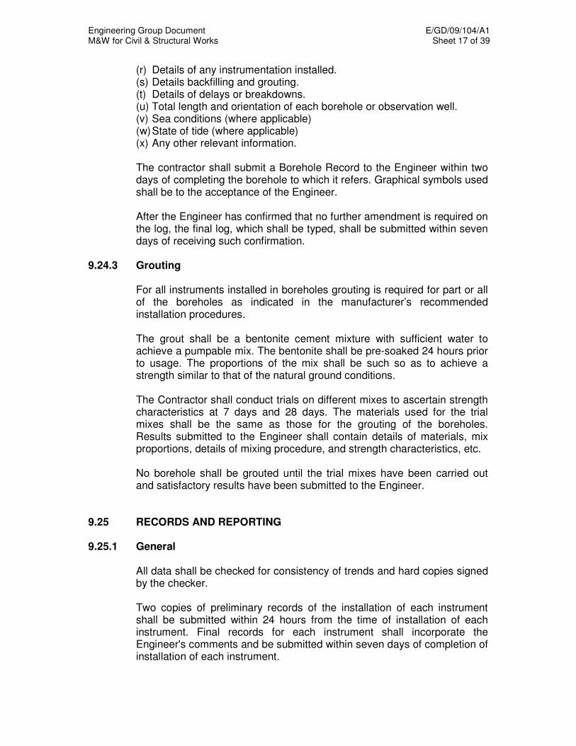
Engineering Group Document E/GD/09/104/A1 M&W for Civil & Structural Works Sheet 17 of 39
(r) Details of any instrumentation installed. (s) Details backfilling and grouting. (t) Details of delays or breakdowns. (u) Total length and orientation of each borehole or observation well. (v) Sea conditions (where applicable) (w) State of tide (where applicable) (x) Any other relevant information.
The contractor shall submit a Borehole Record to the Engineer within two
days of completing the borehole to which it refers. Graphical symbols used shall be to the acceptance of the Engineer.
After the Engineer has confirmed that no further amendment is required on
the log, the final log, which shall be typed, shall be submitted within seven days of receiving such confirmation.
9.24.3 Grouting For all instruments installed in boreholes grouting is required for part or all
of the boreholes as indicated in the manufacturer’s recommended installation procedures.
The grout shall be a bentonite cement mixture with sufficient water to
achieve a pumpable mix. The bentonite shall be pre-soaked 24 hours prior to usage. The proportions of the mix shall be such so as to achieve a strength similar to that of the natural ground conditions.
The Contractor shall conduct trials on different mixes to ascertain strength
characteristics at 7 days and 28 days. The materials used for the trial mixes shall be the same as those for the grouting of the boreholes. Results submitted to the Engineer shall contain details of materials, mix proportions, details of mixing procedure, and strength characteristics, etc.
No borehole shall be grouted until the trial mixes have been carried out
and satisfactory results have been submitted to the Engineer. 9.25 RECORDS AND REPORTING 9.25.1 General All data shall be checked for consistency of trends and hard copies signed
by the checker. Two copies of preliminary records of the installation of each instrument
shall be submitted within 24 hours from the time of installation of each instrument. Final records for each instrument shall incorporate the Engineer's comments and be submitted within seven days of completion of installation of each instrument.
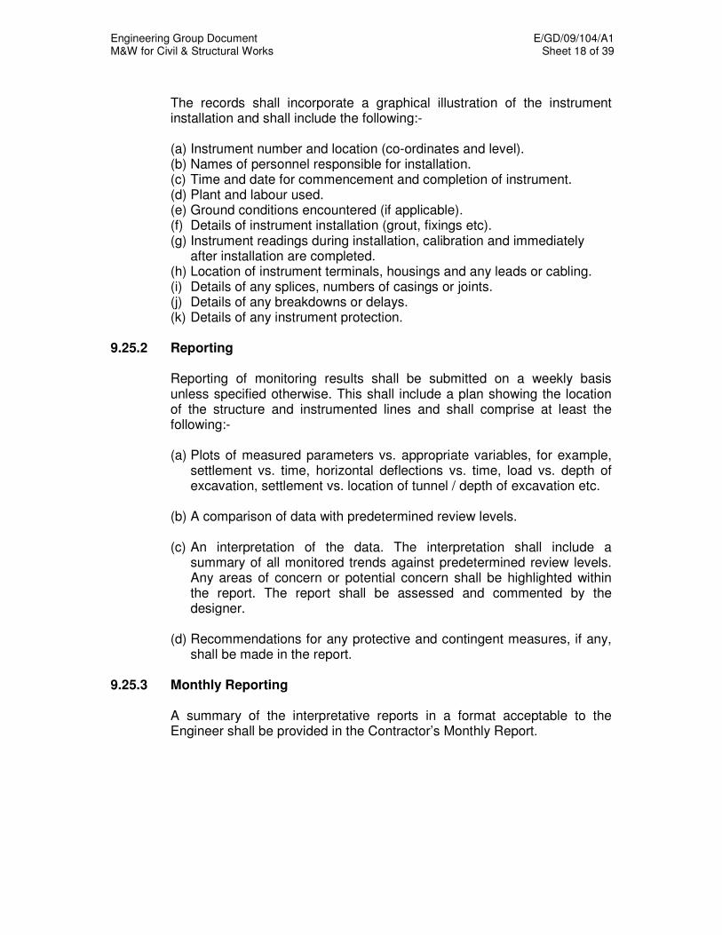
Engineering Group Document E/GD/09/104/A1 M&W for Civil & Structural Works Sheet 18 of 39
The records shall incorporate a graphical illustration of the instrument
installation and shall include the following:-
(a) Instrument number and location (co-ordinates and level). (b) Names of personnel responsible for installation. (c) Time and date for commencement and completion of instrument. (d) Plant and labour used. (e) Ground conditions encountered (if applicable). (f) Details of instrument installation (grout, fixings etc). (g) Instrument readings during installation, calibration and immediately
after installation are completed. (h) Location of instrument terminals, housings and any leads or cabling. (i) Details of any splices, numbers of casings or joints. (j) Details of any breakdowns or delays. (k) Details of any instrument protection.
9.25.2 Reporting Reporting of monitoring results shall be submitted on a weekly basis
unless specified otherwise. This shall include a plan showing the location of the structure and instrumented lines and shall comprise at least the following:-
(a) Plots of measured parameters vs. appropriate variables, for example,
settlement vs. time, horizontal deflections vs. time, load vs. depth of excavation, settlement vs. location of tunnel / depth of excavation etc.
(b) A comparison of data with predetermined review levels. (c) An interpretation of the data. The interpretation shall include a
summary of all monitored trends against predetermined review levels. Any areas of concern or potential concern shall be highlighted within the report. The report shall be assessed and commented by the designer.
(d) Recommendations for any protective and contingent measures, if any,
shall be made in the report. 9.25.3 Monthly Reporting A summary of the interpretative reports in a format acceptable to the
Engineer shall be provided in the Contractor’s Monthly Report.
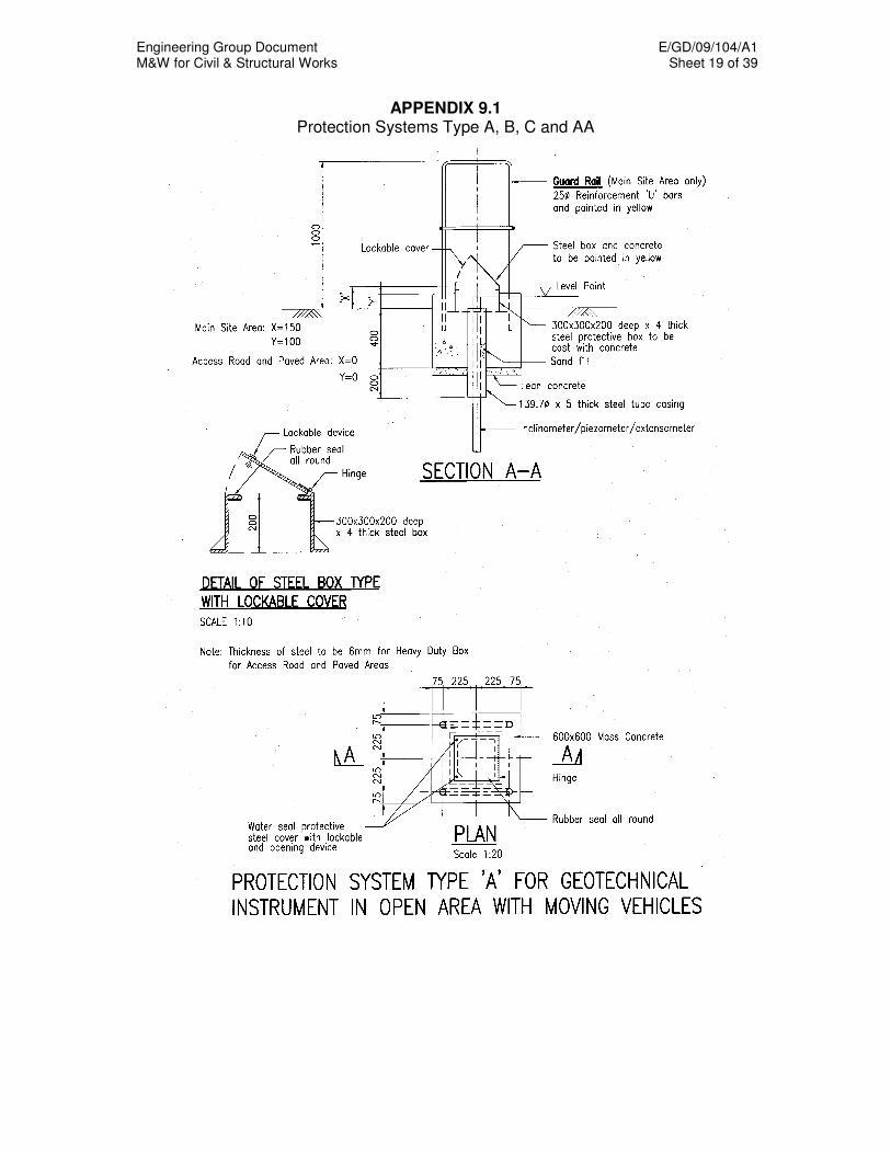
Engineering Group Document E/GD/09/104/A1 M&W for Civil & Structural Works Sheet 19 of 39
APPENDIX 9.1 Protection Systems Type A, B, C and AA
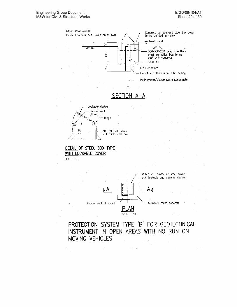
Engineering Group Document E/GD/09/104/A1 M&W for Civil & Structural Works Sheet 20 of 39
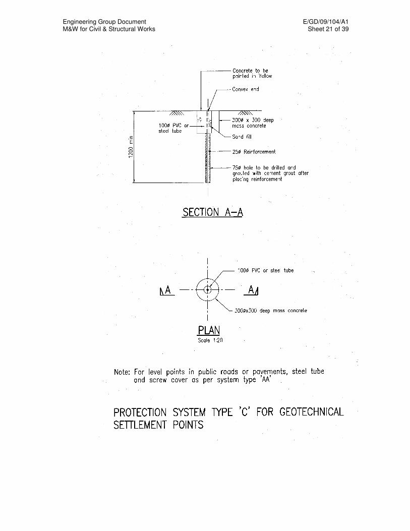
Engineering Group Document E/GD/09/104/A1 M&W for Civil & Structural Works Sheet 21 of 39
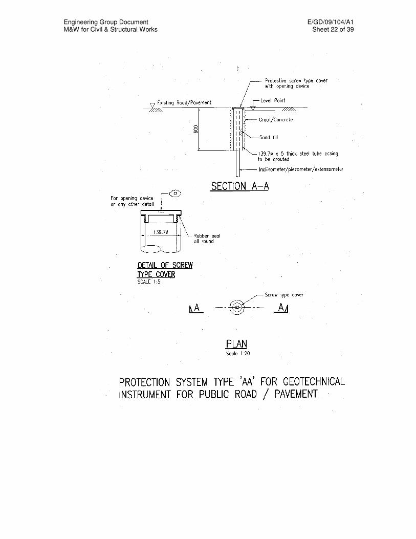
Engineering Group Document E/GD/09/104/A1 M&W for Civil & Structural Works Sheet 22 of 39
Engineering Group Document E/GD/09/104/A1 M&W for Civil & Structural Works Sheet 23 of 39
APPENDIX 9.2
GDB FILE FORMAT
1 INTRODUCTION
This document details the codes, protocols, and formats which have to be
followed by the Contractor while submitting instrumentation information to the GDB.
Contractor will be provided with the Local Data Verifier (LDV) application
for verifying the data before submission to the LTA Engineer.
2 LOCAL DATA VERIFIER (LDV) OVERVIEW
2.1 Purpose
LDV is a local data verifier and validation application. The main purpose of
this module is to perform first level validation of the input data, before submitting it to the LTA Site staff. This application will accept Initial, Zero, Data, Tunnel Initial, and Tunnel Data files in a defined format to perform validation checks before sending validated files to the GDB Admin.
2.2 Components
LDV has two components namely, LDV Admin and LDV User. LDV Admin: - LDV Admin component is to define validation information
and contract site information required for LDV user application. The LTA Engineer will set the validation information for a Contract.
LDV User: - Contractor should use LDV User component to validate input
files based on the information provided in LDV Admin component.

Engineering Group Document E/GD/09/104/A1 M&W for Civil & Structural Works Sheet 24 of 39
2.3 List Of Codes
The following are the list of codes, which should be used while preparing
the data for GDB.
INSTRUMENT TYPE CODE DESCRIPTION CMA Crack Meter (Avongaurd) CMD Crack Meter (Demec) CME Crack Meter (Wire Extensometer)
ED Excavation Depth Monitor GWC Ground Water (Casagrande) GWR Ground Water (Resistance) GWS Ground Water (Standpipe) GWV Ground Water (Wire) I Inclinometer
IE Electrolevel Inclinometer L Level Points MX Magnetic Extensometer PC Pressure Cell RX Rod Extensometer SG Strain Gauge T Temperature Sensor
TAM Tunnel Absolute Movement TD Tunnel Distortion TDT Tunnel Displacement (TE) TE Tape Extensometer TM Tilt Meter VM Vibration Monitor
XYZ 3D Precision Survey
TUNNEL TYPE CODE DISCRIPTION EP Earth Pressure OF Open Face
SL Slurry TB Tunnel boring machine
TUNNEL SUPPORT CODE DESCRIPTION FP Fore polling CA Compressed air GR Grouting
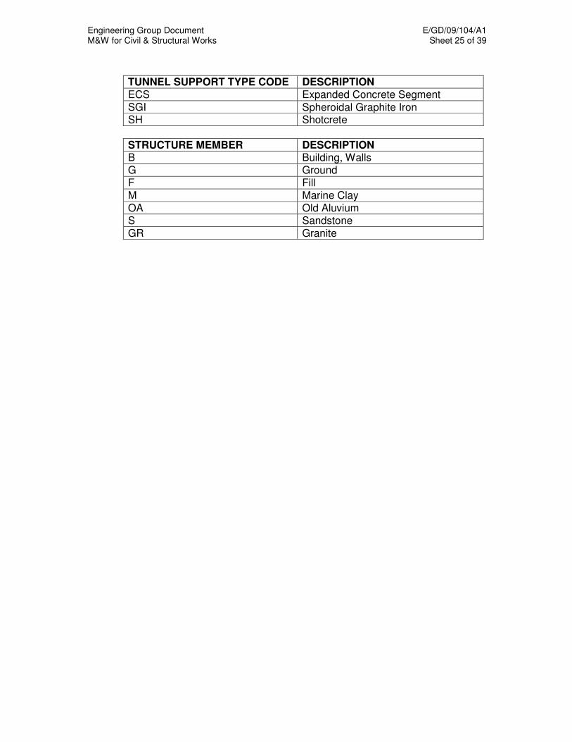
Engineering Group Document E/GD/09/104/A1 M&W for Civil & Structural Works Sheet 25 of 39
TUNNEL SUPPORT TYPE CODE DESCRIPTION ECS Expanded Concrete Segment SGI Spheroidal Graphite Iron SH Shotcrete
STRUCTURE MEMBER DESCRIPTION B Building, Walls G Ground F Fill M Marine Clay
OA Old Aluvium S Sandstone GR Granite

Engineering Group Document E/GD/09/104/A1 M&W for Civil & Structural Works Sheet 26 of 39
3 INPUT FILE FORMATS FOR GDB
3.1 Initial File
An example of the initial file is as shown below: Header Information: Cells A2, A3, A4, A5 and A6 contain header information. These cells will be written by LDV Application. Contractor need not fill these cells.
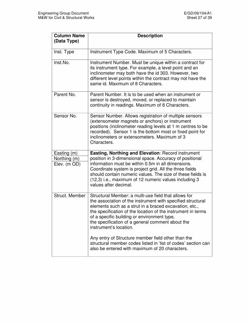
Engineering Group Document E/GD/09/104/A1 M&W for Civil & Structural Works Sheet 27 of 39
Column Name (Data Type)
Description
Inst. Type Instrument Type Code. Maximum of 5 Characters.
Inst.No. Instrument Number. Must be unique within a contract for its instrument type. For example, a level point and an inclinometer may both have the id 303. However, two different level points within the contract may not have the same id. Maximum of 8 Characters.
Parent No. Parent Number. It is to be used when an instrument or sensor is destroyed, moved, or replaced to maintain continuity in readings. Maximum of 8 Characters.
Sensor No. Sensor Number. Allows registration of multiple sensors (extensometer magnets or anchors) or instrument positions (inclinometer reading levels at 1 m centres to be recorded). Sensor 1 is the bottom most or fixed point for inclinometers or extensometers. Maximum of 3 Characters.
Easting (m) Northing (m) Elev. (m OD)
Easting, Northing and Elevation: Record instrument position in 3-dimensional space. Accuracy of positional information must be within 0.5m in all dimensions. Coordinate system is project grid. All the three fields should contain numeric values. The size of these fields is (12,3) i.e., maximum of 12 numeric values including 3 values after decimal.
Struct. Member Structural Member: a multi-use field that allows for the association of the instrument with specified structural elements such as a strut in a braced excavation, etc., the specification of the location of the instrument in terms of a specific building or environment type, the specification of a general comment about the instrument’s location. Any entry of Structure member field other than the structural member codes listed in ‘list of codes’ section can also be entered with maximum of 20 characters.
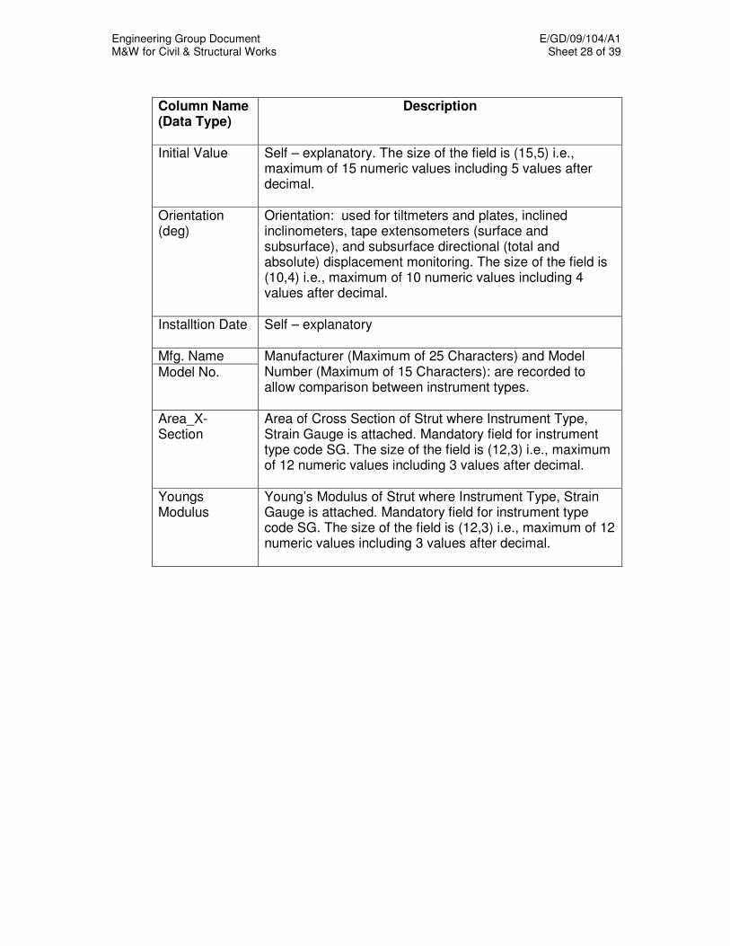
Engineering Group Document E/GD/09/104/A1 M&W for Civil & Structural Works Sheet 28 of 39
Column Name (Data Type)
Description
Initial Value Self – explanatory. The size of the field is (15,5) i.e., maximum of 15 numeric values including 5 values after decimal.
Orientation (deg)
Orientation: used for tiltmeters and plates, inclined inclinometers, tape extensometers (surface and subsurface), and subsurface directional (total and absolute) displacement monitoring. The size of the field is (10,4) i.e., maximum of 10 numeric values including 4 values after decimal.
Installtion Date Self – explanatory
Mfg. Name Model No.
Manufacturer (Maximum of 25 Characters) and Model Number (Maximum of 15 Characters): are recorded to allow comparison between instrument types.
Area_X-Section
Area of Cross Section of Strut where Instrument Type, Strain Gauge is attached. Mandatory field for instrument type code SG. The size of the field is (12,3) i.e., maximum of 12 numeric values including 3 values after decimal.
Youngs Modulus
Young’s Modulus of Strut where Instrument Type, Strain Gauge is attached. Mandatory field for instrument type code SG. The size of the field is (12,3) i.e., maximum of 12 numeric values including 3 values after decimal.
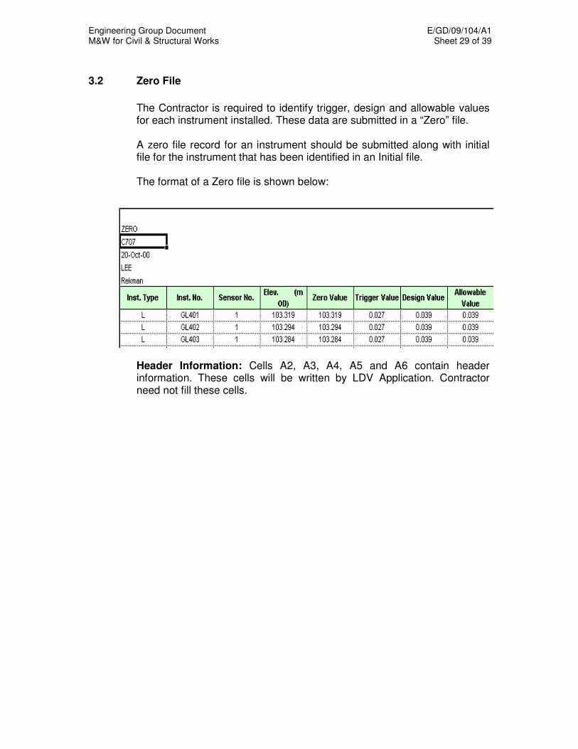
Engineering Group Document E/GD/09/104/A1 M&W for Civil & Structural Works Sheet 29 of 39
3.2 Zero File
The Contractor is required to identify trigger, design and allowable values
for each instrument installed. These data are submitted in a “Zero” file. A zero file record for an instrument should be submitted along with initial
file for the instrument that has been identified in an Initial file. The format of a Zero file is shown below:
Header Information: Cells A2, A3, A4, A5 and A6 contain header information. These cells will be written by LDV Application. Contractor need not fill these cells.
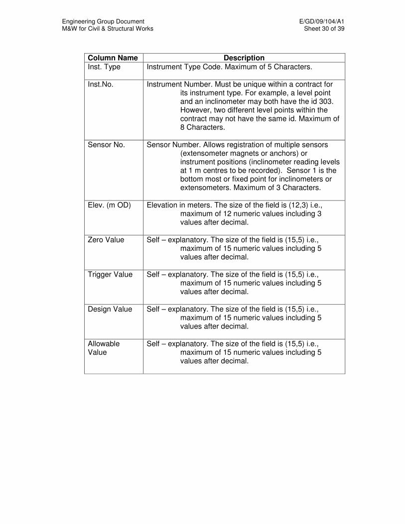
Engineering Group Document E/GD/09/104/A1 M&W for Civil & Structural Works Sheet 30 of 39
Column Name Description Inst. Type Instrument Type Code. Maximum of 5 Characters.
Inst.No. Instrument Number. Must be unique within a contract for
its instrument type. For example, a level point and an inclinometer may both have the id 303. However, two different level points within the contract may not have the same id. Maximum of 8 Characters.
Sensor No. Sensor Number. Allows registration of multiple sensors
(extensometer magnets or anchors) or instrument positions (inclinometer reading levels at 1 m centres to be recorded). Sensor 1 is the bottom most or fixed point for inclinometers or extensometers. Maximum of 3 Characters.
Elev. (m OD) Elevation in meters. The size of the field is (12,3) i.e.,
maximum of 12 numeric values including 3 values after decimal.
Zero Value Self – explanatory. The size of the field is (15,5) i.e., maximum of 15 numeric values including 5 values after decimal.
Trigger Value Self – explanatory. The size of the field is (15,5) i.e.,
maximum of 15 numeric values including 5 values after decimal.
Design Value Self – explanatory. The size of the field is (15,5) i.e.,
maximum of 15 numeric values including 5 values after decimal.
Allowable Value
Self – explanatory. The size of the field is (15,5) i.e., maximum of 15 numeric values including 5 values after decimal.
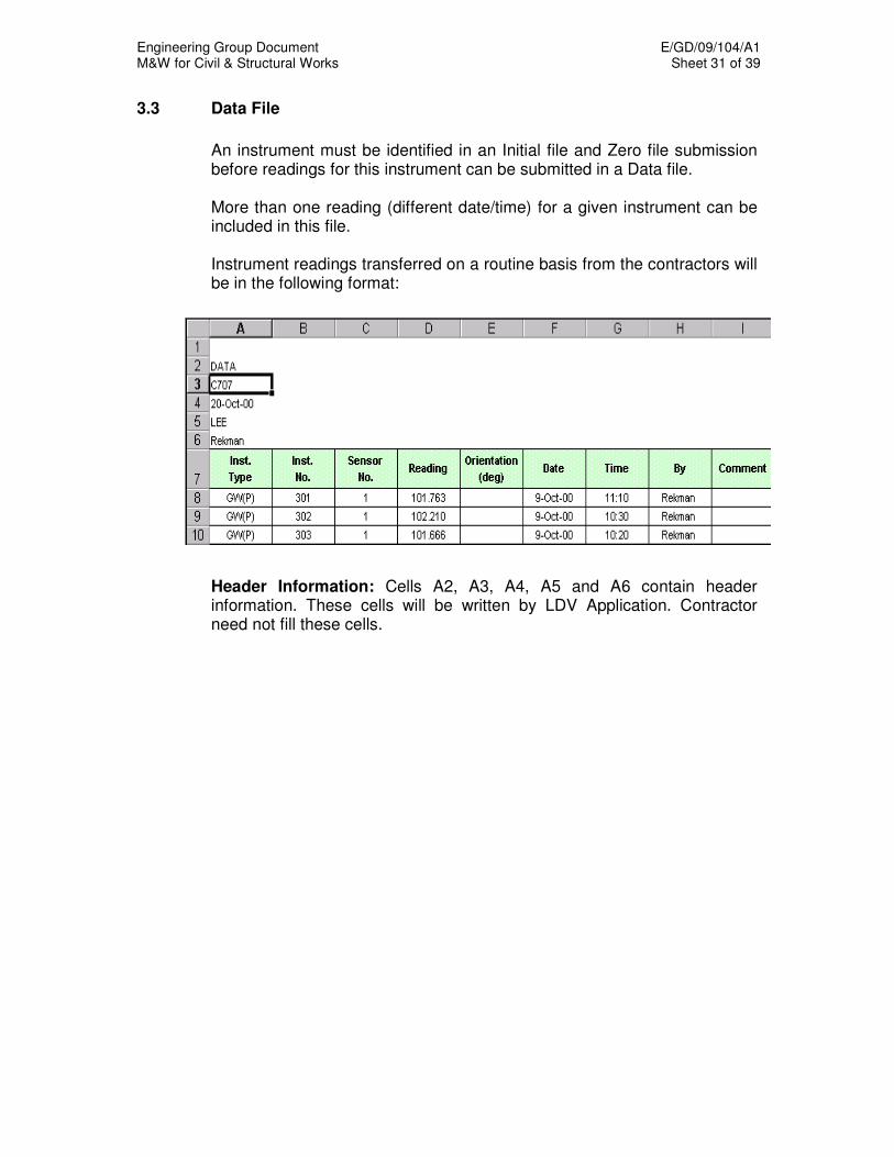
Engineering Group Document E/GD/09/104/A1 M&W for Civil & Structural Works Sheet 31 of 39
3.3 Data File
An instrument must be identified in an Initial file and Zero file submission
before readings for this instrument can be submitted in a Data file. More than one reading (different date/time) for a given instrument can be
included in this file. Instrument readings transferred on a routine basis from the contractors will
be in the following format: Header Information: Cells A2, A3, A4, A5 and A6 contain header
information. These cells will be written by LDV Application. Contractor need not fill these cells.
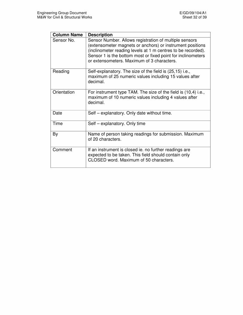
Engineering Group Document E/GD/09/104/A1 M&W for Civil & Structural Works Sheet 32 of 39
Column Name Description Sensor No. Sensor Number. Allows registration of multiple sensors
(extensometer magnets or anchors) or instrument positions (inclinometer reading levels at 1 m centres to be recorded). Sensor 1 is the bottom most or fixed point for inclinometers or extensometers. Maximum of 3 characters.
Reading Self-explanatory. The size of the field is (25,15) i.e., maximum of 25 numeric values including 15 values after decimal.
Orientation For instrument type TAM. The size of the field is (10,4) i.e., maximum of 10 numeric values including 4 values after decimal.
Date Self – explanatory. Only date without time.
Time Self – explanatory. Only time
By Name of person taking readings for submission. Maximum of 20 characters.
Comment If an instrument is closed ie. no further readings are expected to be taken. This field should contain only CLOSED word. Maximum of 50 characters.
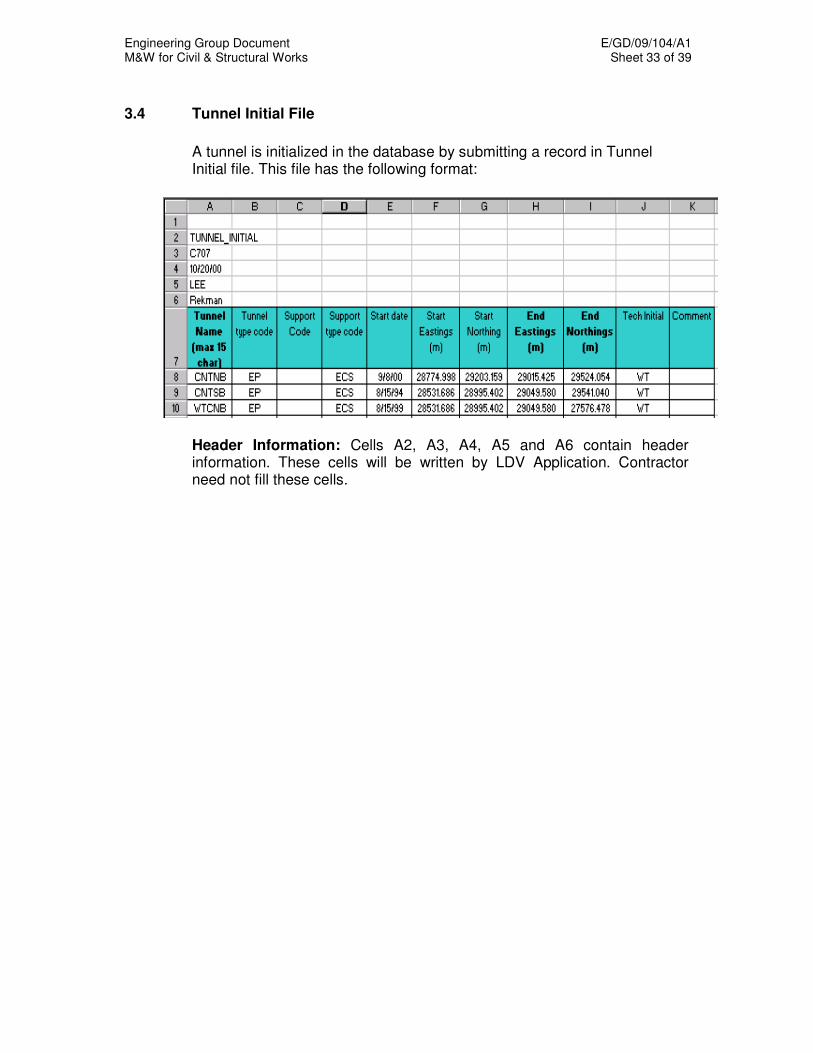
Engineering Group Document E/GD/09/104/A1 M&W for Civil & Structural Works Sheet 33 of 39
3.4 Tunnel Initial File
A tunnel is initialized in the database by submitting a record in Tunnel
Initial file. This file has the following format: Header Information: Cells A2, A3, A4, A5 and A6 contain header
information. These cells will be written by LDV Application. Contractor need not fill these cells.

Engineering Group Document E/GD/09/104/A1 M&W for Civil & Structural Works Sheet 34 of 39
Column Name Description Tunnel Name Self-explanatory. Tunnel name can be any string that
is meaningful to LTA and/or the contractor. It must be unique within a contract but does not have to be unique across the whole project. Tunnel name must be 15 characters or less.
Tunnel Type Code
Should be a valid code as listed in previous chapter. Maximum of 10 characters.
Support Code Should be a valid code as listed in previous chapter. Maximum of 10 characters.
Support Type Code
Should be a valid code as listed in previous chapter. Maximum of 10 characters.
Start Date Self-explanatory
Start Eastings (m)
Self-explanatory. The size of the field is (12,3) i.e., maximum of 12 numeric values including 3 values after decimal.
Start Northings (m)
Self-explanatory. The size of the field is (12,3) i.e., maximum of 12 numeric values including 3 values after decimal.
End Eastings (m)
Self-explanatory. The size of the field is (12,3) i.e., maximum of 12 numeric values including 3 values after decimal.
End Northings (m)
Self-explanatory. The size of the field is (12,3) i.e., maximum of 12 numeric values including 3 values after decimal.
Tech Initial Name of person taking readings for submission. Maximum of 20 characters.
Comment Self-explanatory. Maximum of 50 characters.
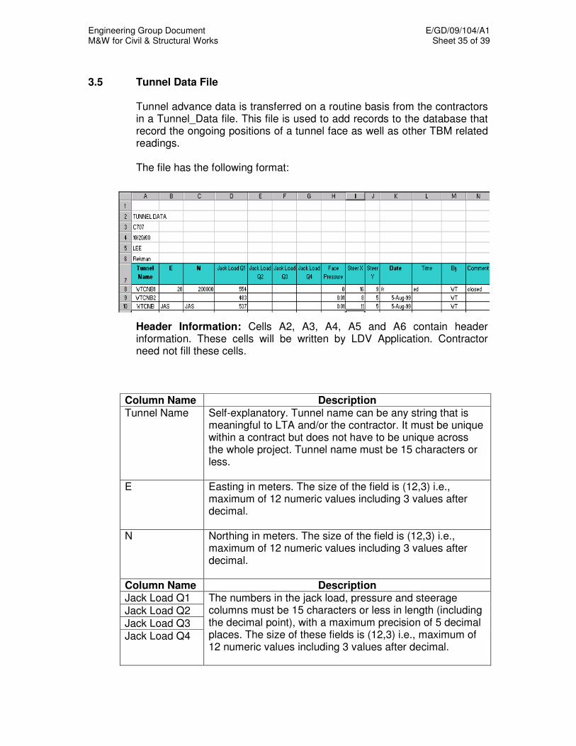
Engineering Group Document E/GD/09/104/A1 M&W for Civil & Structural Works Sheet 35 of 39
3.5 Tunnel Data File Tunnel advance data is transferred on a routine basis from the contractors
in a Tunnel_Data file. This file is used to add records to the database that record the ongoing positions of a tunnel face as well as other TBM related readings.
The file has the following format: Header Information: Cells A2, A3, A4, A5 and A6 contain header
information. These cells will be written by LDV Application. Contractor need not fill these cells.
Column Name Description Tunnel Name Self-explanatory. Tunnel name can be any string that is
meaningful to LTA and/or the contractor. It must be unique within a contract but does not have to be unique across the whole project. Tunnel name must be 15 characters or less.
E Easting in meters. The size of the field is (12,3) i.e., maximum of 12 numeric values including 3 values after decimal.
N Northing in meters. The size of the field is (12,3) i.e., maximum of 12 numeric values including 3 values after decimal.
Column Name Description Jack Load Q1
Jack Load Q2 Jack Load Q3 Jack Load Q4
The numbers in the jack load, pressure and steerage columns must be 15 characters or less in length (including the decimal point), with a maximum precision of 5 decimal places. The size of these fields is (12,3) i.e., maximum of 12 numeric values including 3 values after decimal.

Engineering Group Document E/GD/09/104/A1 M&W for Civil & Structural Works Sheet 36 of 39
Face Pressure Self-explanatory. The size of the field is (12,3) i.e., maximum of 12 numeric values including 3 values after decimal.
Steer X Self-explanatory. The size of the field is (12,3) i.e., maximum of 12 numeric values including 3 values after decimal.
Steer Y Self-explanatory. The size of the field is (12,3) i.e., maximum of 12 numeric values including 3 values after decimal.
Date Date is the date of the reading. Only date without time.
Time Time (optional) is the time of the reading. If omitted, a time of 12:00 noon will be used. Time format is hh:mm
By Name of person taking readings for submission. Maximum of 20 characters.
Comment If an instrument is closed. This field should contain only ‘CLOSED’ word. The comment string (optional) must be 50 characters or less.
Engineering Group Document E/GD/09/104/A1 M&W for Civil & Structural Works Sheet 37 of 39
4 DATA SUBMISSION PROTOCOL
The data submission to GDB shall comply with the following:-
(a) Contractor shall use LDV application for verification of input files and
the applications output files (.zip) should be submitted to LTA staff using floppy disk.
(b) LTA staff will upload these files using GDB browser. (c) Error files and logs files generated by GDB system will be sent back to
Contractor for corrections (Carbon Copy to the Engineer). (d) Contractor shall incorporate the errors and submit (keeping the
filename unchanged) to LDV Application for verification and then submit to LTA staff using floppy disk.
The data submission process to GDB is shown in Flow Diagram 1 below.
4.1 Calibration, Installation and Initialization Records
The contractor is responsible for maintaining a permanent paper record of
each instrument’s installation, calibration and initialization, including:-
(a) Instrument Manufacturer, Model Number, Serial Number and Calibration Certificate (where applicable.) Post-installation value (initial reading.)
(b) Graphical time-series plot demonstrating stability of readings following
instrument installation. For piezometers, these readings will take place over a 2 to 4 week period. For other instruments, readings shall take place during the first several days following instrument installation. For instruments which may be influenced by daily temperature fluctuations (strain gauges, load cells, etc.) readings shall be taken at several points during the thermal cycle to enable identification of the effect (if any) on the instrument readings, so that appropriate compensation can be attempted using the GDB.
(c) Inclinometer casings shall include a deviation and “spiral” test, and
probe calibration shall be maintained and documented as necessary by contractor.

Engineering Group Document E/GD/09/104/A1 M&W for Civil & Structural Works Sheet 38 of 39
4.2 General Notes
Data transmissions shall comply with the following file naming convention:
(Contract No.)_(file type I input D data Z trigger)_(sequential number starting 0001)
e.g. C702_I_0001 (this is the 1st INITIAL file from C702)
C702_Z_0002 (this is the 2nd ZERO file from C702) C702_D_0023 (this is the 23rd DATA file from C702) C702_TI_0042 (this is the 42nd Tunnel Initial file from C702) C702_TD_0043 (this is the 43rd Tunnel Data file from C702) When re-submitting ERROR files, the file names shall not be changed.
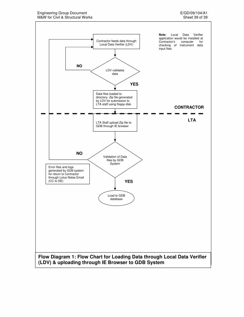
Engineering Group Document E/GD/09/104/A1 M&W for Civil & Structural Works Sheet 39 of 39
Data files loaded to directory. Zip file generated by LDV for submission to LTA staff using floppy disk
Contractor feeds data through
Local Data Verifier (LDV)
Load to GDB database
NO LDV validates
data
Validation of Data
files by GDB System
NO
LTA Staff upload Zip file to GDB through IE browser
Error files and logs generated by GDB system for return to Contractor through Lotus Notes Email (CC to GE)
LTA
CONTRACTOR
YES
YES
Note: Local Data Verifier application would be installed at Contractor’s computer for checking of instrument data input files
Flow Diagram 1: Flow Chart for Loading Data through Local Data Verifier (LDV) & uploading through IE Browser to GDB System
Engineering Group Document E/GD/09/104/A1 M&W for Civil & Structural Works Sheet 1 of 67
CHAPTER 10
ROADWORKS 10.1 GENERAL This Specification is applicable to all road works. This chapter refers closely to ASTM and BS standards. The term asphalt
used in ASTM can be referred to bitumen used in BS. Before work on any pavement above formation level commences all ducts,
drains, and other works beneath the road must be completed and backfilled.
10.2 EARTHWORKS Earthworks below formation level shall comply with the requirements of
Chapter 4, Earthworks. 10.3 FLEXIBLE PAVEMENTS 10.3.1 Subgrade Subgrade shall mean the layer defined as the 500mm of material
immediately below formation level. 10.3.1.1 Materials a) Subgrade Soil The soil used for the subgrade shall have a soaked CBR (California
Bearing Ratio) value of not less than 6%. In addition, the following requirements shall be complied with:
• Subgrade in fill areas shall be formed of material defined as “Suitable Material” in Chapter 4, Earthworks.
• In cut areas where the soaked CBR value of the subgrade is not less than 6%, the Contractor shall compact the top 200mm of the subgrade to the density specified in Chapter 4, Earthworks.
• In the event that the soaked CBR value of the subgrade is less than 6%, the Contractor shall remove and replace the soil with selected fill or stabilise the in-situ soil by approved means to a depth as required by the Engineer.
Engineering Group Document E/GD/09/104/A1 M&W for Civil & Structural Works Sheet 2 of 67
10.3.1.2 Preparation of Subgrade
On areas to be paved, the specified depths in cut areas and fill areas shall be compacted to meet the requirements for field density in Chapter 4, Earthworks. When completed the surface shall be true to the lines, grades and cross section shown on the Drawings. Any irregularities or depressions that develop under rolling shall be corrected by loosening the material at these places and adding, removing, or placing material until the surface is smooth and uniform. Any portion of the area, which is not accessible to a roller, shall be compacted to the required density by approved mechanical tampers.
All soft and yielding material and material which cannot be compacted readily when rolled or tamped shall be removed as directed by the Engineer and replaced with suitable material. After grading operations are completed, all loose stones larger than 50mm in their greatest dimension shall be removed from the surface of all proposed graded paving areas and disposed off.
10.3.1.3 Protection of the Top of Subgrade
At all times, the top of the subgrade shall be kept in such condition that it will drain readily and effectively. The Contractor shall take all necessary precautions to protect the subgrade from damage. He shall limit hauling over the finished subgrade to that which is essential for construction purposes. If ruts are formed, the subgrade shall be reshaped and rolled. Storage or stockpiling of materials on the top of the subgrade shall not be permitted. Until the subgrade had been checked and approved, no sub-base, base course or pavement shall be laid thereon.
10.3.2 Sub-Base and Base 10.3.2.1 General
a) Underlying Course The underlying course shall be checked before placing and spreading
of sub-base or base. Any ruts or soft area shall be corrected and rolled to the required density before the sub-base or base is placed.
To protect the underlying course and to ensure proper drainage, the
spreading of the sub-base or base material shall begin along the centreline of the pavement on a crowned section or on the high side of pavements with a one-way slope.
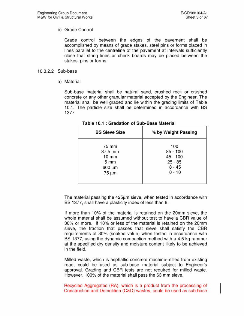
Engineering Group Document E/GD/09/104/A1 M&W for Civil & Structural Works Sheet 3 of 67
b) Grade Control Grade control between the edges of the pavement shall be
accomplished by means of grade stakes, steel pins or forms placed in lines parallel to the centreline of the pavement at intervals sufficiently close that string lines or check boards may be placed between the stakes, pins or forms.
10.3.2.2 Sub-base
a) Material
Sub-base material shall be natural sand, crushed rock or crushed concrete or any other granular material accepted by the Engineer. The material shall be well graded and lie within the grading limits of Table 10.1. The particle size shall be determined in accordance with BS 1377.
Table 10.1 : Gradation of Sub-Base Material
BS Sieve Size % by Weight Passing
75 mm
37.5 mm 10 mm 5 mm
600 µm
75 µm
100
85 - 100 45 - 100 25 - 85 8 - 45 0 - 10
The material passing the 425µm sieve, when tested in accordance with BS 1377, shall have a plasticity index of less than 6. If more than 10% of the material is retained on the 20mm sieve, the whole material shall be assumed without test to have a CBR value of 30% or more. If 10% or less of the material is retained on the 20mm sieve, the fraction that passes that sieve shall satisfy the CBR requirements of 30% (soaked value) when tested in accordance with BS 1377, using the dynamic compaction method with a 4.5 kg rammer at the specified dry density and moisture content likely to be achieved in the field. Milled waste, which is asphaltic concrete machine-milled from existing road, could be used as sub-base material subject to Engineer’s approval. Grading and CBR tests are not required for milled waste. However, 100% of the material shall pass the 63 mm sieve.
Recycled Aggregates (RA), which is a product from the processing of Construction and Demolition (C&D) wastes, could be used as sub-base
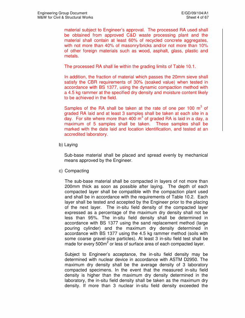
Engineering Group Document E/GD/09/104/A1 M&W for Civil & Structural Works Sheet 4 of 67
material subject to Engineer’s approval. The processed RA used shall be obtained from approved C&D waste processing plant and the material shall contain at least 60% of recycled concrete aggregates, with not more than 40% of masonry/bricks and/or not more than 10% of other foreign materials such as wood, asphalt, glass, plastic and metals. The processed RA shall lie within the grading limits of Table 10.1. In addition, the fraction of material which passes the 20mm sieve shall satisfy the CBR requirements of 30% (soaked value) when tested in accordance with BS 1377, using the dynamic compaction method with a 4.5 kg rammer at the specified dry density and moisture content likely to be achieved in the field. Samples of the RA shall be taken at the rate of one per 100 m
3 of
graded RA laid and at least 3 samples shall be taken at each site in a day. For site where more than 400 m
3 of graded RA is laid in a day, a
maximum of 5 samples shall be taken. These samples shall be marked with the date laid and location identification, and tested at an accredited laboratory.
b) Laying Sub-base material shall be placed and spread evenly by mechanical
means approved by the Engineer. c) Compacting
The sub-base material shall be compacted in layers of not more than 200mm thick as soon as possible after laying. The depth of each compacted layer shall be compatible with the compaction plant used and shall be in accordance with the requirements of Table 10.2. Each layer shall be tested and accepted by the Engineer prior to the placing of the next layer. The in-situ field density of the compacted layer expressed as a percentage of the maximum dry density shall not be less than 95%. The in-situ field density shall be determined in accordance with BS 1377 using the sand replacement method (large pouring cylinder) and the maximum dry density determined in accordance with BS 1377 using the 4.5 kg rammer method (soils with some coarse gravel-size particles). At least 3 in-situ field test shall be made for every 500m
2 or less of surface area of each compacted layer.
Subject to Engineer’s acceptance, the in-situ field density may be determined with nuclear device in accordance with ASTM D2950. The maximum dry density shall be the average density of 3 laboratory compacted specimens. In the event that the measured in-situ field density is higher than the maximum dry density determined in the laboratory, the in-situ field density shall be taken as the maximum dry density. If more than 3 nuclear in-situ field density exceeded the
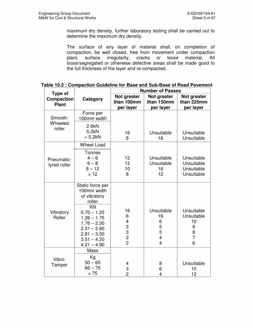
Engineering Group Document E/GD/09/104/A1 M&W for Civil & Structural Works Sheet 5 of 67
maximum dry density, further laboratory testing shall be carried out to determine the maximum dry density. The surface of any layer of material shall, on completion of compaction, be well closed, free from movement under compaction plant, surface irregularity, cracks or loose material. All loose/segregated or otherwise defective areas shall be made good to the full thickness of the layer and re-compacted.
Table 10.2 : Compaction Guideline for Base and Sub-Base of Road Pavement
Number of Passes Type of
Compaction Plant
Category Not greater than 100mm
per layer
Not greater than 150mm
per layer
Not greater than 225mm
per layer Force per
100mm width Smooth-Wheeled
roller
2.6kN 5.2kN
> 5.2kN
16 8
Unsuitable 16
Unsuitable Unsuitable
Pneumatic-tyred roller
Wheel Load
Tonnes 4 – 6 6 – 8 8 – 12 > 12
12 12 10 8
Unsuitable Unsuitable
16 12
Unsuitable Unsuitable Unsuitable Unsuitable
Static force per 100mm width of vibratory
roller
Vibratory Roller
KN 0.70 – 1.25 1.26 – 1.75 1.76 – 2.30 2.31 – 2.80 2.81 – 3.50 3.51 – 4.20 4.21 – 4.90
16 6 4 3 3 2 2
Unsuitable 16 6 5 5 4 4
Unsuitable Unsuitable
10 9 8 7 6
Mass
Vibro-Tamper
Kg 50 – 65 66 – 75
> 75
4 3 2
8 6 4
Unsuitable 10 12
Engineering Group Document E/GD/09/104/A1 M&W for Civil & Structural Works Sheet 6 of 67
10.3.2.3 Plant-mixed Graded Granite Aggregate Base a) Aggregate
The base aggregate shall consist of graded crushed, clean and hard angular aggregate complying with the requirements of SS 31 and conforming to the gradation shown in Table 10.3.
Table 10.3 : Gradation of Plant-mixed Graded Granite Aggregate
Aggregates BS Sieve Size % by Weight Passing
Coarse Aggregate
50mm
37.5mm 20mm 10mm 5mm
100
95-100 60-80 40-60 25-45
Fine Aggregate
2.36mm
425µm 15-35 6-18
Mineral Filler
75 µm
0-10
When used in a pavement which is to carry a asphalt layer, that portion
of the soil-binder material (if any) which passes a 425µm sieve shall have the following properties:
. Liquid Limit - not more than 25% . Plasticity Index - not more than 6% . Linear Shrinkage - not more than 3%
The sand equivalent of the material passing the 4.8mm sieve shall not be less than 30%. When used in a pavement which is not to carry a asphalt layer surfacing,
the portion of the soil-binder material (if any) which passes a 425 µm sieve shall have the following properties:
. Liquid Limit - not more than 35% . Plasticity Index - between 4 and 9% . Linear Shrinkage - between 2 and 4%

Engineering Group Document E/GD/09/104/A1 M&W for Civil & Structural Works Sheet 7 of 67
b) Mixing
The aggregates shall be mixed at a mixing plant by continuous mixing using a pug-mill mixer, or batch type mixing using a revolving blade, rotary pan, or rotary tilting drum mixer. The plant shall be in sound mechanical condition and shall consistently produce a uniform mixture of aggregates and water at optimum moisture content or at a moisture content as directed by the Engineer. To achieve the desired grading, the approved sand, granite dust or filler such as laterite, shall be used. Water used for mixing shall be clean and free from detrimental impurities.
c) Transporting Plant-mixed material shall be transported directly to the point where it
is to be laid, and shall be covered with canvas or other approved material to prevent loss of moisture. Transport vehicles shall be equipped with discharge devices that will enable the plant-mixed material to be discharged or loaded into the hoppers of spreading machines without spillage and in such a way that segregation will be minimised.
d) Quality Control Samples of graded granite aggregates shall be taken at the rate of one
per 100 m3 of graded granite aggregate laid and at least 3 samples
shall be taken at each site in a day. For site where more than 400m3 of
graded granite aggregate is laid in a day, a maximum of 5 samples shall be taken. These samples shall be marked with the date laid and location identification, and tested at an accredited laboratory.
e) Laying and Compacting The material shall be deposited and spread in lanes in uniform layers
of not more than 150mm thick such that the thickness of the final compacted layer shall not exceed 250mm. The base material shall be spread by an approved self-propelled mechanical spreader with an automatic tamping device.
After spreading, the base material shall be thoroughly compacted by
rolling to obtain a level, even and uniformly compacted base. Rolling shall continue until the base material is compacted to a dry
density of not less than 98% of the maximum dry density as determined in accordance with BS 1377, using the vibrating hammer method. In-situ dry density tests shall be carried out in accordance with the sand replacement method (large pouring cylinder) specified in BS 1377.
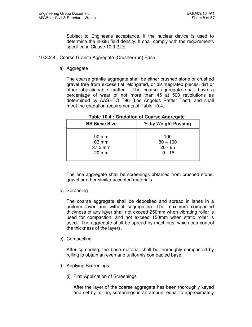
Engineering Group Document E/GD/09/104/A1 M&W for Civil & Structural Works Sheet 8 of 67
Subject to Engineer’s acceptance, if the nuclear device is used to
determine the in-situ field density. It shall comply with the requirements specified in Clause 10.3.2.2c.
10.3.2.4 Coarse Granite Aggregate (Crusher-run) Base
a) Aggregate The coarse granite aggregate shall be either crushed stone or crushed
gravel free from excess flat, elongated, or disintegrated pieces, dirt or other objectionable matter. The coarse aggregate shall have a percentage of wear of not more than 45 at 500 revolutions as determined by AASHTO T96 (Los Angeles Rattler Test), and shall meet the gradation requirements of Table 10.4.
Table 10.4 : Gradation of Coarse Aggregate
BS Sieve Size % by Weight Passing
90 mm 63 mm
37.5 mm 20 mm
100
80 – 100 20 - 65 0 - 15
The fine aggregate shall be screenings obtained from crushed stone,
gravel or other similar accepted materials. b) Spreading
The coarse aggregate shall be deposited and spread in lanes in a
uniform layer and without segregation. The maximum compacted thickness of any layer shall not exceed 250mm when vibrating roller is used for compaction, and not exceed 150mm when static roller is used. The aggregate shall be spread by machines, which can control the thickness of the layers.
c) Compacting After spreading, the base material shall be thoroughly compacted by
rolling to obtain an even and uniformly compacted base. d) Applying Screenings
(i) First Application of Screenings
After the layer of the coarse aggregate has been thoroughly keyed and set by rolling, screenings in an amount equal to approximately

Engineering Group Document E/GD/09/104/A1 M&W for Civil & Structural Works Sheet 9 of 67
50% of that required to fill the interstices shall be applied gradually over the surface.
(ii) Second Application of Screenings
The second application of screenings, which consists of about 25% of the total required amount, shall then follow.
(iii) Third Application of Screenings
The remaining 25% of the required screenings shall be applied after the completion of the second application of screenings.
The screening in each application shall be spread in thin layers with rolling and when necessary the screening shall be swept into the voids. The process of spreading, rolling and brooming of screenings shall stop until no more screening can be forced into the voids of the coarse aggregates.
e) Sprinkling Immediately after the voids of the coarse aggregate have been filled
with screenings, the surface of the base course layer shall be sprinkled with water. This shall be followed by rolling. The sprinkling and rolling shall continue and additional screenings applied where necessary until all voids are completely filled and the coarse aggregate firmly set and bonded.
f) Laying of Coarse Aggregate (Crusher-run) on Existing Flexible
Pavement Where existing flexible pavements are to be raised with coarse granite
aggregate, the Contractor shall scarify the existing asphalt pavement surfaces with scarifying tyres fixed to rollers or with scarifying tyres of a motor graded for a depth of at least 50mm below the pavement surfaces.
All such scarified asphalt materials shall be removed before coarse
aggregate is placed, rolled and applied with screenings as specified in this Specification.
10.3.2.5 Recycled Concrete Aggregate (RCA) Base a) RCA
RCA is crushed concrete obtained from construction and demolition (C&D) waste. RCA used shall be obtained from approved C&D waste processing plant.
Engineering Group Document E/GD/09/104/A1 M&W for Civil & Structural Works Sheet 10 of 67
Processed RCA shall consist essentially of aggregate and cementitious materials such as cement paste and mortar. The processing shall include but not be limited to the following processes:
(i) Crushing (ii) Removal of ferrous metals (iii) Screening and removal of foreign materials such as brick,
ceramic, wood, plastic and asphaltic material (iv) Sieving of RCA into the required sizes Besides complying with the requirements of SS 31, the percentage of the impurity (by mass) and acid-soluble sulphate shall not exceed 5% and 1% respectively. In addition, the gradation and the liquid limit, plasticity index and linear shrinkage of fine aggregates shall comply with the requirements as shown in Table 10.3 and Clause 10.3.2.3 accordingly. If graded RCA is added with additives such as cement or other additives, the supplier shall provide the information on the type of additives used. Additives used shall be approved material which is environmentally safe. The supplier shall provide information of the bound graded RCA such as 7-day compressive strength, method statement of construction and curing requirement to ensure the quality control and proper laying of the material.
b) Mixing
Processed RCA shall be mixed at a mixing plant by continuous mixing using a pug-mill mixer, or batch type mixing using a revolving blade, rotary pan, or rotary tilting drum mixer. The plant shall be in sound mechanical condition and shall consistently produce a uniform mixture of aggregates and water at optimum moisture content or at moisture content as directed by the Engineer. Water used for mixing shall be clean and free from detrimental impurities.
c) Transporting
Plant-mixed graded RCA shall be transported directly to the point where it is to be laid, and shall be covered with canvas or other approved material to prevent loss of moisture. Transport vehicles shall be equipped with discharge devices that will enable the plant-mixed graded RCA to be discharged or loaded into the hoppers of spreading machines without spillage and in such a way that segregation will be minimised.
Engineering Group Document E/GD/09/104/A1 M&W for Civil & Structural Works Sheet 11 of 67
d) Quality Control
Sample of graded RCA shall be taken at the rate of one per 100 m3 of
graded RCA laid and at least 3 samples shall be taken at each site in a day. For site where more than 400 m
3 of graded RCA is laid in a
day, a maximum of 5 samples shall be taken. These samples shall be marked with the date laid and location identification, and tested at an accredited laboratory.
e) Laying and Compacting
Plant-mixed RCA shall be deposited and spread in lanes in uniform layers of not more than 150 mm thick such that the thickness of the final compacted layer shall not exceed 250 mm. Spreading shall be carried out by an approved self-propelled mechanical spreader with an automatic tamping device. After spreading, the graded RCA shall be thoroughly compacted to obtain a level, even and uniformly compacted base. Rolling shall continue until the graded RCA is compacted to a dry density of not less than 98% of the maximum dry density as determined in accordance with BS 1377, using the vibrating hammer method. In-situ dry density tests shall be carried out in accordance with the sand replacement method (large pouring cylinder) specified in BS 1377. Subject to Engineer’s acceptance, if a nuclear device is used to determine the in-situ field density, it shall comply with the requirements specified in Clause 10.3.2.2c.
10.3.2.6 Incineration Bottom Ash Sub-Base and Base
a) Material Incineration bottom ash (IBA) is a residual product of the combustion of
municipal solid waste primarily composed of ceramics, slags, glassy material and some ferrous / non-ferrous metals. Processed IBA could be used as sub-base and base material subject to compliance with environmental requirements set by relevant agencies, and the approval of relevant agencies and the Engineer.
The gradation and CBR requirements for processed IBA shall in
accordance with Clause 10.3.2.2(a). b) Mixing The processed IBA shall be mixed at a mixing plant by continuous
mixing using a pug-mill mixer, or batch type mixing using a revolving
Engineering Group Document E/GD/09/104/A1 M&W for Civil & Structural Works Sheet 12 of 67
blade, rotary pan, or rotary tilting drum mixer. The processed IBA shall be blended with water and additives (if required) to produce a uniform mixture at optimum moisture content.
The optimum moisture content and maximum dry density of the final
product shall be determined in the laboratory according to BS 1377, by an accredited testing laboratory.
Water used for mixing shall be clean and free from detrimental
impurities. c) Storage The processed IBA shall be stored at a storage area with proper
drainage facilities (approved by NEA) to collect leachate from the stockpile. All leachate collected shall be disposed by a license waste collector. No storage of IBA on site shall be allowed.
d) Transporting Plant-mixed material shall be transported directly to the point where it
is to be laid, and shall be properly sealed and covered with canvas or other approved material to prevent leakage and loss of moisture. Transport vehicles shall be equipped with discharge devices that will enable the plant-mixed material to be discharged or loaded into the hoppers of spreading machines without spillage and in such a way that segregation will be minimised.
e) Quality Control The requirements for quality control of plant-mixed materials at site
shall be in accordance with Clause 10.3.2.3(d). f) Laying and Compacting The requirements for laying and compacting of plant-mixed materials at
site shall be in accordance with Clause 10.3.2.3(e). 10.3.3 Asphaltic Concrete 10.3.3.1 Materials a) Aggregates
Aggregates shall consist of crushed stone, crushed gravel or crushed slag with or without sand or other inert finely divided mineral aggregate. Based on sieve analysis, aggregates shall be classified as shown in Table 10.5.
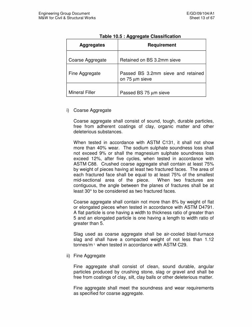
Engineering Group Document E/GD/09/104/A1 M&W for Civil & Structural Works Sheet 13 of 67
Table 10.5 : Aggregate Classification
Aggregates Requirement
Coarse Aggregate
Retained on BS 3.2mm sieve
Fine Aggregate
Passed BS 3.2mm sieve and retained
on 75 µm sieve
Mineral Filler
Passed BS 75 µm sieve
i) Coarse Aggregate
Coarse aggregate shall consist of sound, tough, durable particles, free from adherent coatings of clay, organic matter and other deleterious substances. When tested in accordance with ASTM C131, it shall not show more than 40% wear. The sodium sulphate soundness loss shall not exceed 9% or shall the magnesium sulphate soundness loss exceed 12%, after five cycles, when tested in accordance with ASTM C88. Crushed coarse aggregate shall contain at least 75% by weight of pieces having at least two fractured faces. The area of each fractured face shall be equal to at least 75% of the smallest mid-sectional area of the piece. When two fractures are contiguous, the angle between the planes of fractures shall be at
least 30° to be considered as two fractured faces. Coarse aggregate shall contain not more than 8% by weight of flat or elongated pieces when tested in accordance with ASTM D4791. A flat particle is one having a width to thickness ratio of greater than 5 and an elongated particle is one having a length to width ratio of greater than 5. Slag used as coarse aggregate shall be air-cooled blast-furnace slag and shall have a compacted weight of not less than 1.12 tonnes/m³ when tested in accordance with ASTM C29.
ii) Fine Aggregate Fine aggregate shall consist of clean, sound durable, angular
particles produced by crushing stone, slag or gravel and shall be free from coatings of clay, silt, clay balls or other deleterious matter.
Fine aggregate shall meet the soundness and wear requirements
as specified for coarse aggregate.
Engineering Group Document E/GD/09/104/A1 M&W for Civil & Structural Works Sheet 14 of 67
The fine aggregate with any blended filler shall have a plasticity
index not greater than 6%, and a liquid limit of not more than 25% when tested in accordance with ASTM D4318 and in addition shall have a silt content of not greater than 0.3% of the total weight when tested in accordance with SS73.
Natural sand, when added to produce the desired gradation or to
increase the workability or compatibility of the mixture shall be limited to 15% by weight.
iii) Filler Filler shall meet the requirements of ASTM D242.
b) Bitumen Emulsion
The bitumen emulsion shall be homogeneous after thorough mixing, for at least 30 days after delivery. The bitumen emulsion shall be rapid setting cationic bitumen emulsion. The properties and the method of testings of the bitumen emulsion shall comply with the requirements specified in SS 85.
c) Bitumen All bitumen shall be petroleum bitumen of 60/70 penetration grade. No
mineral matter other than that naturally contained in such bitumen shall be present. The bitumen shall be homogeneous, free from water and shall not foam when heated to 175
oC. The bitumen shall comply to the
requirements of Table 10.6.

Engineering Group Document E/GD/09/104/A1 M&W for Civil & Structural Works Sheet 15 of 67
Table 10.6 : Requirements for Bitumen
60/70 Penetration Grade
Property
Unit
Min Max
Method of
Testing
Penetrating at 25°C 100g, 5s Flash Point, Cleveland Open Cup Ductility at 25°C, 5 cm per min Solubility in trichloroethylene Softening Point, Ring and Ball Specific Gravity at 25°C Thin-film oven test, 3.2 mm, 163°C, 5 hrs : a) Loss on heating b) Penetration of residue at 25°C c) Ductility of residue at 25°C, 5 cm per min
0.1 mm
°C
cm
% wt
°C -
% wt
% of original
cm
60
232
100
99
47
1.0 -
54
50
70
- - -
56
1.11
0.8 - -
SS 86
Engineering Group Document E/GD/09/104/A1 M&W for Civil & Structural Works Sheet 16 of 67
d) Admixture The use of any admixture added to the asphaltic concrete mix shall be
acceptable to the Engineer. The Contractor shall furnish all relevant technical information, specifications, test reports and job reference of the admixture.
The Contractor shall obtain representative sample and test the
samples of the admixture at an accredited laboratory and submit the test results to the Engineer.
Any admixture, which fails to comply with the requirements, shall be
rejected. All costs incurred in testing shall be borne by the Contractor. e) Water Water used in diluting the bitumen emulsion or wetting the wheels of
rollers shall be clean and free from detrimental impurities. The water shall be obtained from a public supply where possible and
may be obtained from any other source if approved by Engineer.
10.3.3.2 Mix Design 10.3.3.2.1 Dense Mix a) Aggregate Grading
All aggregate grading for the different types of mixes shall be in accordance with Table 10.7.

Engineering Group Document E/GD/09/104/A1 M&W for Civil & Structural Works Sheet 17 of 67
Table 10.7: Mix Specification
Mix Classification Road Mixes
Type of Mix
W3B Wearing Course
B1 Binder Course
Thickness of Course 40 – 65 mm 50 - 100 mm
Max Size of Stone 19 mm 35 mm
(BS) Passing 50 mm
37.5 mm 25 mm 19 mm
13.2 mm 9.5 mm 6.3 mm
3.35 mm 1.18 mm
300 µm
75 µm
- - -
100 85 – 95
- 58 – 68 40 – 50 21 – 31 11 – 17
4 – 8
-
100 95 – 100 84 – 92 65 – 82
- 48 – 62 35 – 50 22 – 35 12 – 19
3 – 8
Min Max Min Max % Soluble Bitumen (60/70 Penetration Grade) (% by Weight of Total Mix)
4.5 5.5 4.5 5.5
b) Marshall Design Criteria All samples tested for Marshall Design Criteria shall conform to the
requirements of Table 10.8.
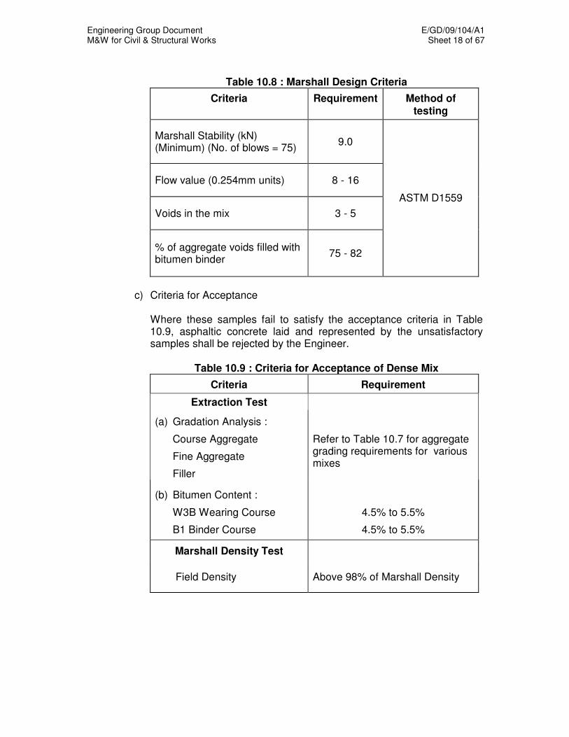
Engineering Group Document E/GD/09/104/A1 M&W for Civil & Structural Works Sheet 18 of 67
Table 10.8 : Marshall Design Criteria
Criteria Requirement Method of testing
Marshall Stability (kN) (Minimum) (No. of blows = 75)
9.0
Flow value (0.254mm units) 8 - 16
Voids in the mix 3 - 5
% of aggregate voids filled with bitumen binder
75 - 82
ASTM D1559
c) Criteria for Acceptance Where these samples fail to satisfy the acceptance criteria in Table
10.9, asphaltic concrete laid and represented by the unsatisfactory samples shall be rejected by the Engineer.
Table 10.9 : Criteria for Acceptance of Dense Mix
Criteria Requirement
Extraction Test
(a) Gradation Analysis :
Course Aggregate
Fine Aggregate
Filler
Refer to Table 10.7 for aggregate grading requirements for various mixes
(b) Bitumen Content :
W3B Wearing Course
B1 Binder Course
4.5% to 5.5%
4.5% to 5.5%
Marshall Density Test
Field Density Above 98% of Marshall Density

Engineering Group Document E/GD/09/104/A1 M&W for Civil & Structural Works Sheet 19 of 67
10.3.3.2.2 Porous Asphalt
a) Aggregate and Binder
The coarse aggregate shall comply with the specifications as follow: i) Coarse aggregates shall consist of clean, well-graded, angular,
crushed granite stone of approved quality, free from dust, dirt and other deleterious materials; and free from excess of flat elongated or weathered pieces.
ii) Notwithstanding what is specified under Clause 10.3.3.1a (i), the
properties of the coarse aggregate shall conform to Table 10.10.
Table 10.10: Properties of Coarse Aggregate
Allowable Standard for Different Types of Mix
Property Method
of Testing
Porous Asphalt / Open Graded
Asphalt
Stone Mastic Asphalt
Impact Value BS 812 : Part 112
Not more than 25% Not more than 25%
Crushing Value BS 812 : Part 110
Not more than 25% Not more than 25%
Water Absorption (in terms of surface dry mass)
BS 812 : Part 2
Not more than 1% Not more than 1%
Flakiness Index BS 812 : Part 105.1
Not more than 25% Not more than 25%
Elongation Index BS 812 : Part 105.2
Not more than 30% Not more than 35%
L.A. Abrasion Value (500 revolutions)
SS 73 Not more than 20% Not more than 25%
Silt Content of Aggregate in Hot Bin (by Weight)
SS 73 Not more than 0.3% Not more than 0.3%
The polymer modified bitumen shall have a performance grade not lower than PG-76 of the Performance Grade Asphalt Binder Specifications shown in Table 10.11.
The Contractor shall furnish sufficient technical data and test reports as evidence that the polymer modified bitumen is suitable for the production of porous asphaltic concrete before any work commences.
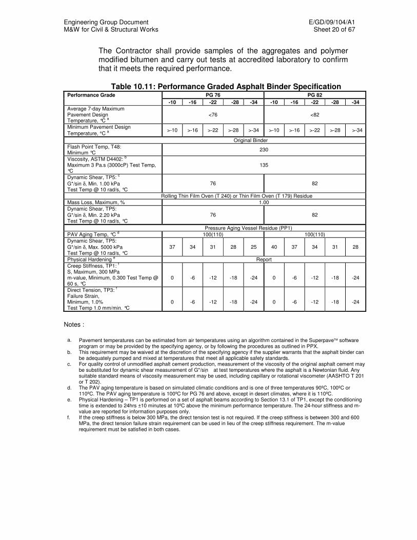
Engineering Group Document E/GD/09/104/A1 M&W for Civil & Structural Works Sheet 20 of 67
The Contractor shall provide samples of the aggregates and polymer modified bitumen and carry out tests at accredited laboratory to confirm that it meets the required performance.
Table 10.11: Performance Graded Asphalt Binder Specification
Performance Grade PG 76 PG 82
-10 -16 -22 -28 -34 -10 -16 -22 -28 -34
Average 7-day Maximum Pavement Design Temperature, °C
a
<76 <82
Minimum Pavement Design
Temperature, °C a
>-10 >-16 >-22 >-28 >-34 >-10 >-16 >-22 >-28 >-34
Original Binder
Flash Point Temp, T48: Minimum °C
230
Viscosity, ASTM D4402: b
Maximum 3 Pa.s (3000cP) Test Temp, °C
135
Dynamic Shear, TP5: c
G*/sin δ, Min. 1.00 kPa Test Temp @ 10 rad/s, °C
76 82
Rolling Thin Film Oven (T 240) or Thin Film Oven (T 179) Residue
Mass Loss, Maximum, % 1.00
Dynamic Shear, TP5:
G*/sin δ, Min. 2.20 kPa Test Temp @ 10 rad/s, °C
76 82
Pressure Aging Vessel Residue (PP1)
PAV Aging Temp, °C d 100(110) 100(110)
Dynamic Shear, TP5:
G*/sin δ, Max. 5000 kPa Test Temp @ 10 rad/s, °C
37 34 31 28 25 40 37 34 31 28
Physical Hardening e Report
Creep Stiffness, TP1: f
S, Maximum, 300 MPa m-value, Minimum, 0.300 Test Temp @ 60 s, °C
0
-6
-12
-18
-24
0
-6
-12
-18
-24
Direct Tension, TP3: f
Failure Strain, Minimum, 1.0% Test Temp 1.0 mm/min. °C
0
-6
-12
-18
-24
0
-6
-12
-18
-24
Notes :
a. Pavement temperatures can be estimated from air temperatures using an algorithm contained in the Superpave software
program or may be provided by the specifying agency, or by following the procedures as outlined in PPX. b. This requirement may be waived at the discretion of the specifying agency if the supplier warrants that the asphalt binder can
be adequately pumped and mixed at temperatures that meet all applicable safety standards. c. For quality control of unmodified asphalt cement production, measurement of the viscosity of the original asphalt cement may
be substituted for dynamic shear measurement of G*/sin at test temperatures where the asphalt is a Newtonian fluid. Any suitable standard means of viscosity measurement may be used, including capillary or rotational viscometer (AASHTO T 201 or T 202).
d. The PAV aging temperature is based on simulated climatic conditions and is one of three temperatures 90ºC, 100ºC or 110ºC. The PAV aging temperature is 100ºC for PG 76 and above, except in desert climates, where it is 110ºC.
e. Physical Hardening – TP1 is performed on a set of asphalt beams according to Section 13.1 of TP1, except the conditioning time is extended to 24hrs ±10 minutes at 10ºC above the minimum performance temperature. The 24-hour stiffness and m-value are reported for information purposes only.
f. If the creep stiffness is below 300 MPa, the direct tension test is not required. If the creep stiffness is between 300 and 600 MPa, the direct tension failure strain requirement can be used in lieu of the creep stiffness requirement. The m-value requirement must be satisfied in both cases.

Engineering Group Document E/GD/09/104/A1 M&W for Civil & Structural Works Sheet 21 of 67
b) Job Mix Design The Contractor shall propose a job mix design to the Engineer for
approval. The specification shown in Table 10.12 for Porous Asphalt may be used as a guide for the job mix design.
The target binder content shall be determined by the Contractor using
an approved binder drainage test and the test report shall be submitted to the Engineer with the proposed mix design. The range of the proposed binder content shall not exceed 1%.
The abrasion loss value for Marshall (50 blow) samples shall not be
more than 15%. This value is the weight loss in percentage of the weight of a sample, after 300 revolutions in a Los Angeles drum, without balls and at controlled temperature. Three samples shall be tested in the laboratory trial and witnessed by the Engineer.
Laboratory and field trials shall be carried out to demonstrate to the
Engineer that the proposed mix design comply with the requirements and criteria for acceptance before the Open Graded Asphalt can be used in the site. The compaction requirements and the number of passes shall be established in the field trial and are to be strictly followed in the construction process.
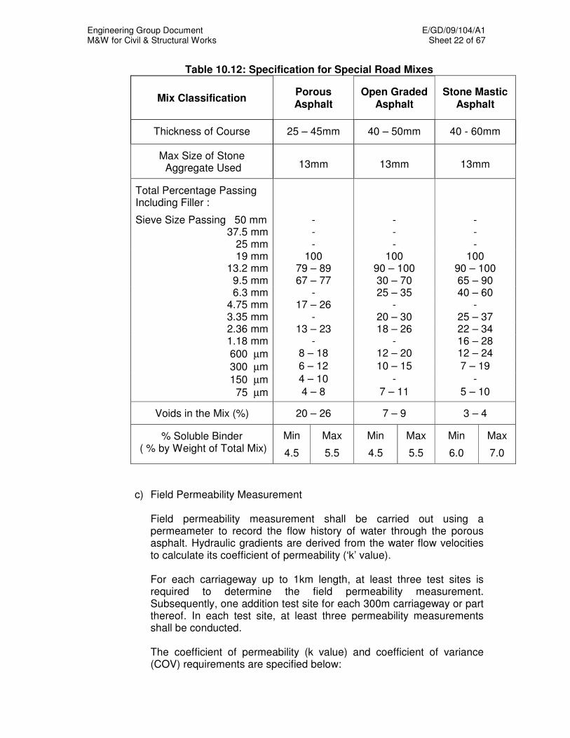
Engineering Group Document E/GD/09/104/A1 M&W for Civil & Structural Works Sheet 22 of 67
Table 10.12: Specification for Special Road Mixes
Mix Classification Porous Asphalt
Open Graded Asphalt
Stone Mastic Asphalt
Thickness of Course 25 – 45mm 40 – 50mm 40 - 60mm
Max Size of Stone Aggregate Used 13mm 13mm 13mm
Total Percentage Passing Including Filler :
Sieve Size Passing 50 mm - - - 37.5 mm - - -
25 mm - - - 19 mm 100 100 100
13.2 mm 79 – 89 90 – 100 90 – 100 9.5 mm 67 – 77 30 – 70 65 – 90 6.3 mm - 25 – 35 40 – 60
4.75 mm 17 – 26 - - 3.35 mm - 20 – 30 25 – 37 2.36 mm 13 – 23 18 – 26 22 – 34 1.18 mm - - 16 – 28
600 µm 8 – 18 12 – 20 12 – 24
300 µm 6 – 12 10 – 15 7 – 19
150 µm 4 – 10 - -
75 µm 4 – 8 7 – 11 5 – 10
Voids in the Mix (%) 20 – 26 7 – 9 3 – 4
% Soluble Binder ( % by Weight of Total Mix)
Min
4.5
Max
5.5
Min
4.5
Max
5.5
Min
6.0
Max
7.0
c) Field Permeability Measurement Field permeability measurement shall be carried out using a
permeameter to record the flow history of water through the porous asphalt. Hydraulic gradients are derived from the water flow velocities to calculate its coefficient of permeability (‘k’ value).
For each carriageway up to 1km length, at least three test sites is
required to determine the field permeability measurement. Subsequently, one addition test site for each 300m carriageway or part thereof. In each test site, at least three permeability measurements shall be conducted.
The coefficient of permeability (k value) and coefficient of variance (COV) requirements are specified below:
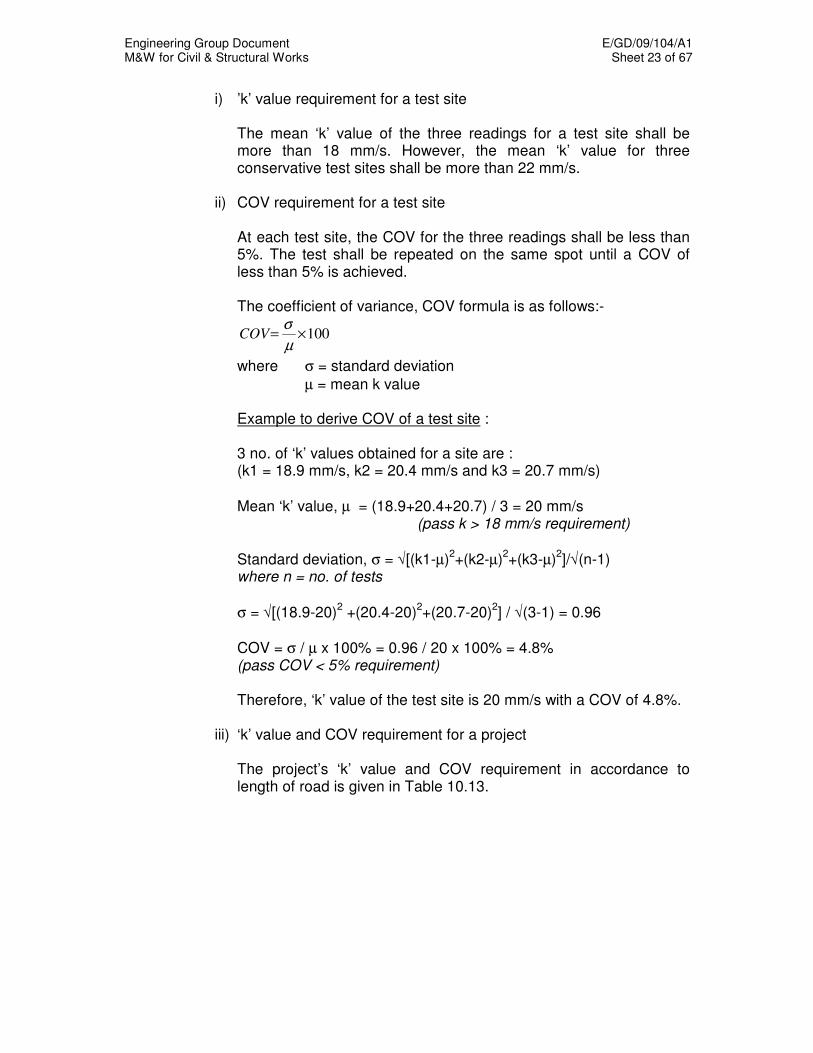
Engineering Group Document E/GD/09/104/A1 M&W for Civil & Structural Works Sheet 23 of 67
i) ’k’ value requirement for a test site
The mean ‘k’ value of the three readings for a test site shall be more than 18 mm/s. However, the mean ‘k’ value for three conservative test sites shall be more than 22 mm/s.
ii) COV requirement for a test site
At each test site, the COV for the three readings shall be less than 5%. The test shall be repeated on the same spot until a COV of less than 5% is achieved.
The coefficient of variance, COV formula is as follows:-
100×=µ
σCOV
where σ = standard deviation
µ = mean k value
Example to derive COV of a test site : 3 no. of ‘k’ values obtained for a site are : (k1 = 18.9 mm/s, k2 = 20.4 mm/s and k3 = 20.7 mm/s)
Mean ‘k’ value, µ = (18.9+20.4+20.7) / 3 = 20 mm/s (pass k > 18 mm/s requirement)
Standard deviation, σ = √[(k1-µ)2+(k2-µ)
2+(k3-µ)
2]/√(n-1)
where n = no. of tests
σ = √[(18.9-20)2 +(20.4-20)
2+(20.7-20)
2] / √(3-1) = 0.96
COV = σ / µ x 100% = 0.96 / 20 x 100% = 4.8% (pass COV < 5% requirement)
Therefore, ‘k’ value of the test site is 20 mm/s with a COV of 4.8%.
iii) ‘k’ value and COV requirement for a project
The project’s ‘k’ value and COV requirement in accordance to length of road is given in Table 10.13.
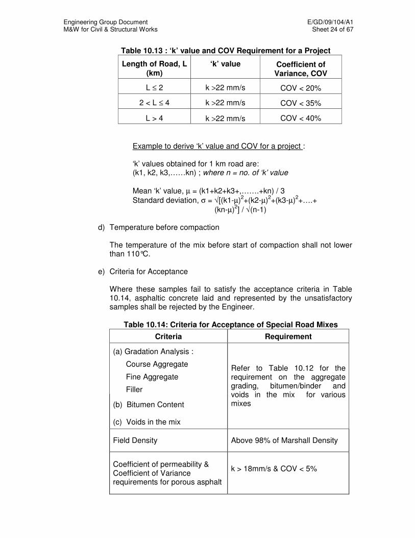
Engineering Group Document E/GD/09/104/A1 M&W for Civil & Structural Works Sheet 24 of 67
Table 10.13 : ‘k’ value and COV Requirement for a Project
Length of Road, L (km)
‘k’ value Coefficient of Variance, COV
L ≤ 2 k >22 mm/s COV < 20%
2 < L ≤ 4 k >22 mm/s COV < 35%
L > 4 k >22 mm/s COV < 40%
Example to derive ‘k’ value and COV for a project : ‘k’ values obtained for 1 km road are: (k1, k2, k3,……kn) ; where n = no. of ‘k’ value
Mean ‘k’ value, µ = (k1+k2+k3+,…….+kn) / 3
Standard deviation, σ = √[(k1-µ)2+(k2-µ)
2+(k3-µ)
2+….+
(kn-µ)2] / √(n-1)
d) Temperature before compaction The temperature of the mix before start of compaction shall not lower
than 110°C. e) Criteria for Acceptance Where these samples fail to satisfy the acceptance criteria in Table
10.14, asphaltic concrete laid and represented by the unsatisfactory samples shall be rejected by the Engineer.
Table 10.14: Criteria for Acceptance of Special Road Mixes
Criteria Requirement
(a) Gradation Analysis :
Course Aggregate
Fine Aggregate
Filler
(b) Bitumen Content
(c) Voids in the mix
Refer to Table 10.12 for the requirement on the aggregate grading, bitumen/binder and voids in the mix for various mixes
Field Density Above 98% of Marshall Density
Coefficient of permeability & Coefficient of Variance requirements for porous asphalt
k > 18mm/s & COV < 5%
Engineering Group Document E/GD/09/104/A1 M&W for Civil & Structural Works Sheet 25 of 67
10.3.3.2.3 Open Graded Asphalt
a) Aggregate and Binder The aggregate and binder of Open Graded Asphalt shall comply with
Clause 10.3.3.2.2(a). b) Job Mix Design The Contractor shall propose a job mix design to the Engineer for
approval. The specification in Table 10.12 for Open Graded Asphalt may be used as a guide for the job mix design.
The acceptable range in the binder content shall be ±0.5% from the
target binder content by mass of total mixture. The coarse aggregate fraction shall not be less than 75% by weight of
the total aggregate content. The voids in mineral aggregate shall not be less than 17%.
The abrasion loss value for Marshall (50 blow) samples shall not be
more than 5%. This value is the weight loss in percentage of the weight of a sample, after 300 revolutions in a Los Angeles drum, without balls and at a controlled temperature. Three samples shall be tested in the laboratory trial and witnessed by the Engineer.
Laboratory and field trials shall be carried out to demonstrate to the
Engineer that the proposed mix design comply with the requirements and criteria for acceptance before the Open Graded Asphalt can be used in the site.
c) Production, Construction and Completion The Contractor shall comply with the following requirements for
temperature control:
i) Mixing temperature not higher than 175 °C.
ii) Laying temperature at time of spreading not lower than 140 °C.
iii) Temperature before start of compaction not lower than 120 °C.
The Contractor may submit propose changes to the temperature
requirements together with his proposed mix design, otherwise the Open Graded Asphalt shall be rejected at the Contractor’s own cost if the temperature requirements are not satisfied.
The Contractor shall demonstrate and establish the number of passes
required for compaction in the field trial. However during construction, the Contractor shall still ensure that the acceptance criteria is achieved and shall increase the number of passes as necessary.
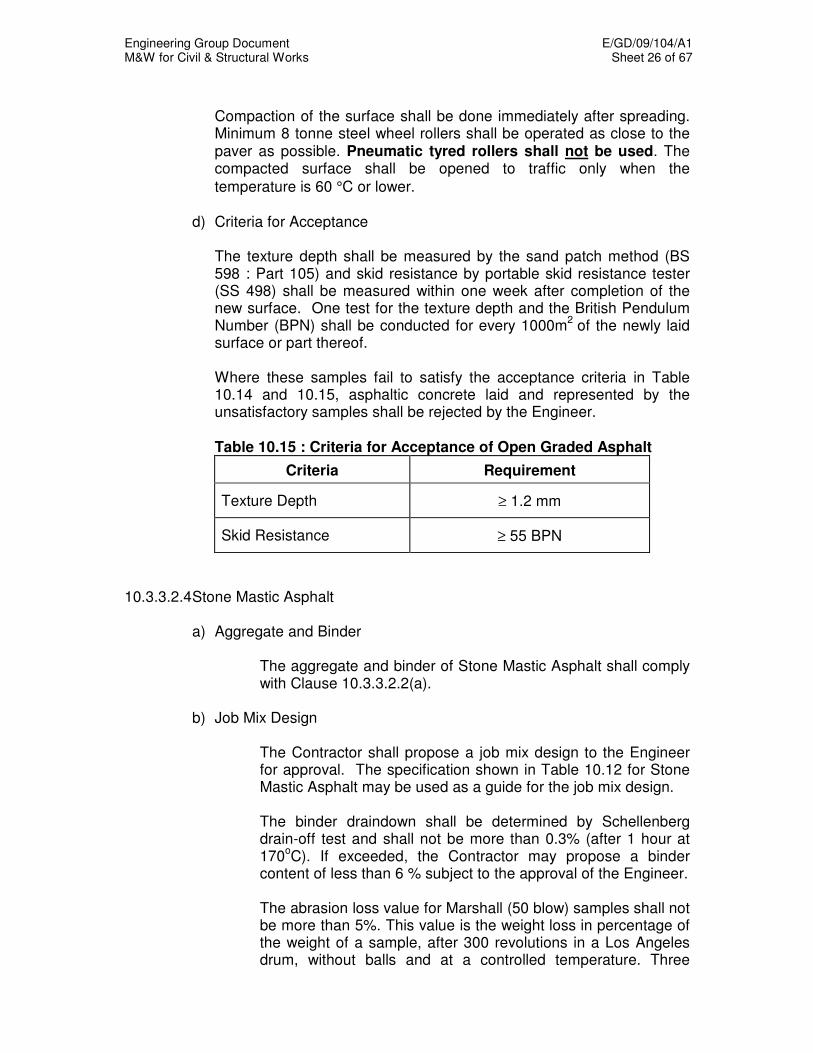
Engineering Group Document E/GD/09/104/A1 M&W for Civil & Structural Works Sheet 26 of 67
Compaction of the surface shall be done immediately after spreading.
Minimum 8 tonne steel wheel rollers shall be operated as close to the paver as possible. Pneumatic tyred rollers shall not be used. The compacted surface shall be opened to traffic only when the
temperature is 60 °C or lower. d) Criteria for Acceptance The texture depth shall be measured by the sand patch method (BS
598 : Part 105) and skid resistance by portable skid resistance tester (SS 498) shall be measured within one week after completion of the new surface. One test for the texture depth and the British Pendulum Number (BPN) shall be conducted for every 1000m
2 of the newly laid
surface or part thereof. Where these samples fail to satisfy the acceptance criteria in Table
10.14 and 10.15, asphaltic concrete laid and represented by the unsatisfactory samples shall be rejected by the Engineer. Table 10.15 : Criteria for Acceptance of Open Graded Asphalt
Criteria Requirement
Texture Depth ≥ 1.2 mm
Skid Resistance ≥ 55 BPN
10.3.3.2.4 Stone Mastic Asphalt
a) Aggregate and Binder
The aggregate and binder of Stone Mastic Asphalt shall comply with Clause 10.3.3.2.2(a).
b) Job Mix Design
The Contractor shall propose a job mix design to the Engineer for approval. The specification shown in Table 10.12 for Stone Mastic Asphalt may be used as a guide for the job mix design.
The binder draindown shall be determined by Schellenberg drain-off test and shall not be more than 0.3% (after 1 hour at 170
oC). If exceeded, the Contractor may propose a binder
content of less than 6 % subject to the approval of the Engineer.
The abrasion loss value for Marshall (50 blow) samples shall not be more than 5%. This value is the weight loss in percentage of the weight of a sample, after 300 revolutions in a Los Angeles drum, without balls and at a controlled temperature. Three
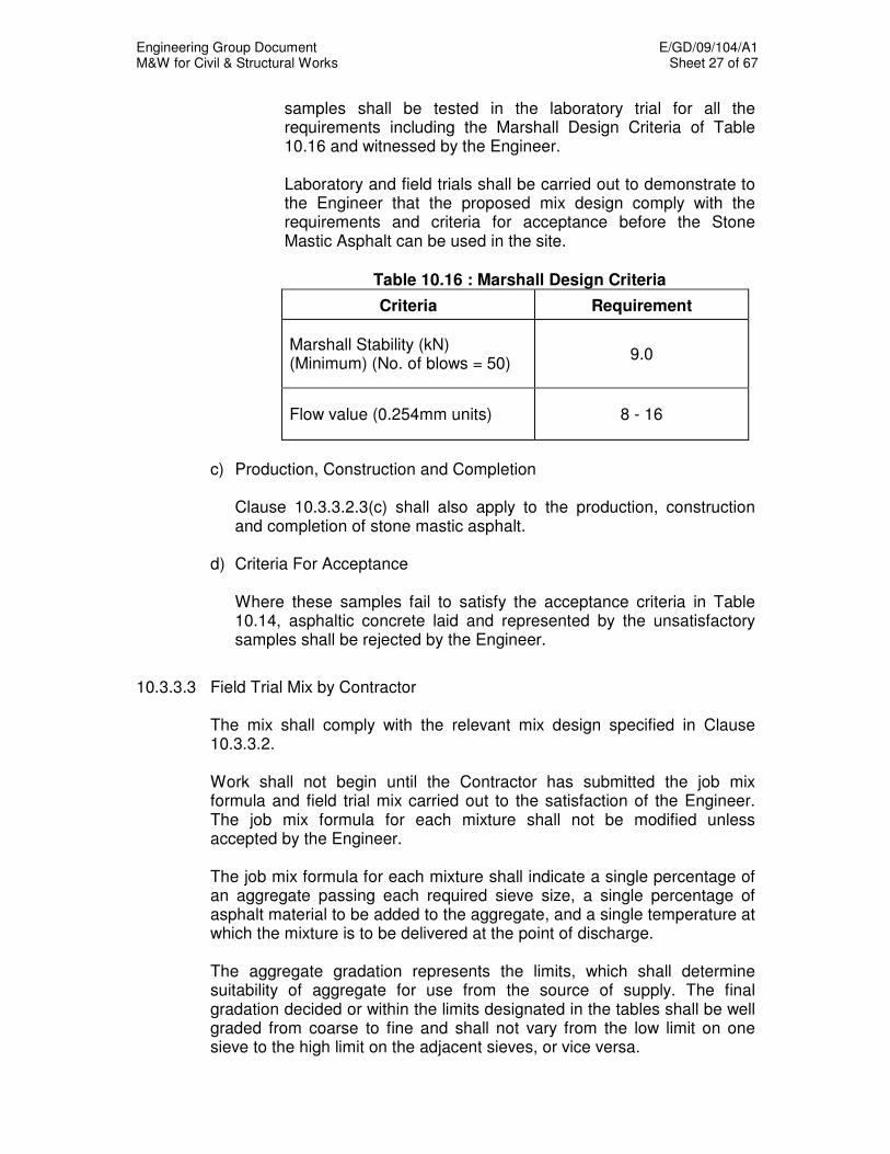
Engineering Group Document E/GD/09/104/A1 M&W for Civil & Structural Works Sheet 27 of 67
samples shall be tested in the laboratory trial for all the requirements including the Marshall Design Criteria of Table 10.16 and witnessed by the Engineer. Laboratory and field trials shall be carried out to demonstrate to the Engineer that the proposed mix design comply with the requirements and criteria for acceptance before the Stone Mastic Asphalt can be used in the site.
Table 10.16 : Marshall Design Criteria
Criteria Requirement
Marshall Stability (kN) (Minimum) (No. of blows = 50)
9.0
Flow value (0.254mm units) 8 - 16
c) Production, Construction and Completion Clause 10.3.3.2.3(c) shall also apply to the production, construction
and completion of stone mastic asphalt. d) Criteria For Acceptance Where these samples fail to satisfy the acceptance criteria in Table
10.14, asphaltic concrete laid and represented by the unsatisfactory samples shall be rejected by the Engineer.
10.3.3.3 Field Trial Mix by Contractor The mix shall comply with the relevant mix design specified in Clause
10.3.3.2. Work shall not begin until the Contractor has submitted the job mix
formula and field trial mix carried out to the satisfaction of the Engineer. The job mix formula for each mixture shall not be modified unless accepted by the Engineer.
The job mix formula for each mixture shall indicate a single percentage of
an aggregate passing each required sieve size, a single percentage of asphalt material to be added to the aggregate, and a single temperature at which the mixture is to be delivered at the point of discharge.
The aggregate gradation represents the limits, which shall determine
suitability of aggregate for use from the source of supply. The final gradation decided or within the limits designated in the tables shall be well graded from coarse to fine and shall not vary from the low limit on one sieve to the high limit on the adjacent sieves, or vice versa.

Engineering Group Document E/GD/09/104/A1 M&W for Civil & Structural Works Sheet 28 of 67
10.3.3.4 Manufacture a) Asphaltic Concrete Mixing Plants The Contractor shall furnish the Engineer in advance with full details of
all asphalt mixing plants to be used in accordance with the format shown in Table 10.17.
The mixing plant shall have an average output capacity of not less than
100 tonnes/hr. Before the mixing plant can be used, the measuring, recording
mechanism and temperature control gauges shall be tested by Singapore Accreditation Council or other internationally recognised bodies in accordance to the manufacturer's specification. The Contractor shall submit the calibration certificates to the Engineer.
The Engineer shall have access at all times to the plant, storage yard
and other facilities for processing the material. He shall be at liberty to take samples of materials, as he deems necessary.
Table 10.17: Format for Submitting Details of Asphalt Mixing Plant
Asphalt Mixing Plant
1 Type, model and manufacturer of plant for production of premix 2 Age of plant
*Batch/Continuous
Feed Manufacture ____________________
Model_______________
Capacity Rating _________________
______________ years
3 Average output capacity in tonnes per hour 4 Location of plant 5 State whether the location of plant is approved by the relevant authority and its permanency 6 If temporary site, state the period for which the plant is allowed to operate
______________ tonnes/hr ** _________years/months
* Delete where not applicable. ** Proof of approval shall be required.

Engineering Group Document E/GD/09/104/A1 M&W for Civil & Structural Works Sheet 29 of 67
b) Heating of Bitumen Binder The binder shall be separately heated in approved heating tanks.
Thermometers shall be provided both in the storage tanks and also on the mixing platform. The temperature dials shall be readily accessible and kept clean at all times.
The bitumen of 60/70 penetration grade shall be heated to 150 -
165°C.
The difference in temperature between the aggregate and the bitumen
shall not exceed 15°C.
c) Drying and Heating of Aggregates The plant shall include at least two cold-hoppers for coarse aggregate
and one for fine aggregate. When two or more fine aggregates are being incorporated in the mixture, a separate hopper shall be provided for each. The feed gates or other devices provided for controlling the output from each hopper shall be capable of accurate adjustment to ensure uniform rate of feed.
When loading the cold hoppers, care shall be taken to avoid
segregation of the aggregate and they shall be kept sufficiently full to allow an even flow through the feed gates.
Aggregates shall be thoroughly dry before mixing, and the Contractor
shall carry out moisture test at least once a week on a sample from each hot bin to check the effectiveness of the drying processes. If at any time the tests indicate that the drying facilities are inadequate, mixing shall cease until the Contractor has augmented his drying capability to the satisfaction of the Engineer. All drying plant shall be equipped with efficient dust extractors.
A suitable thermometer for measuring the temperature of the
aggregate shall be fitted at the drier discharge and shall be maintained in good working order.
d) Mixing Temperature The Contractor shall ensure that the batching of the aggregates and
bitumen, the dry and wet mixing time, the temperatures for the heating of the aggregates and the mix shall be accurately controlled to produce a uniformly coated and acceptable mix within the limits specified.
The aggregate shall be heated to between 150°C to 170°C.
Overheating of the aggregate or binder shall be prohibited and rejected mixture shall not be used.
After heating, the hot aggregate shall be thoroughly and intimately
mixed together with filler and bitumen binder in the correct proportion
Engineering Group Document E/GD/09/104/A1 M&W for Civil & Structural Works Sheet 30 of 67
until every particle of aggregate is completely coated. The total mixing time may only be reduced if the Engineer is satisfied that thorough mixing can be achieved in less time.
Extracted dust shall be automatically fed back into the dry or wet
admixtures. When it satisfies the specified requirements for filler, it shall be weighed into the mixture as a separate proportion. All mixing plant shall incorporate means of access to each hot bin to enable samples to be taken. The aggregate after drying and heating in a drum dryer shall be screened into at least 3 different sizes. The aggregates shall then be stored in separate hot bins for subsequent batching by weight. The use of drum mix plant, which does not incorporate this requirement, shall be prohibited.
After mixing, the asphaltic concrete shall then be discharged directly
into a truck and properly covered with a canvas cover. The temperature of the mix at this stage shall be between 140ºC to 160ºC. The asphaltic concrete shall be rejected at the Contractor’s own cost if the temperature of the hotmix measured at the truck is above 160ºC or below 140ºC.
10.3.3.5 Asphalt Laying a) Construction Method i) Asphaltic Concrete Finisher The Contractor shall furnish the Engineer in advance with full
details of the asphaltic concrete paver to be used, including date of manufacture, model, whether tracked or wheeled, previous usage, maintenance facilities, and all other relevant particulars required by the Engineer.
The asphaltic concrete paver shall be a self-contained, power
propelled unit, provided with an adjustable activated screed or strike off assembly, heated if necessary and capable of spreading and finishing courses of asphalt plant mix materials in lane widths, to the specified thickness. The asphalt paver must be able to operate at various rates of travel consistent with the rate of delivery and the type of asphalt mixture to be laid. Pavers used for shoulders and similar construction shall be capable of spreading and finishing courses of asphalt plant mix materials in the required width.
The paver shall be equipped with a receiving hopper having
sufficient capacity for a uniform spreading operation. The hopper shall be equipped with a distribution system to place the mixture uniformly in front of the screed, which shall effectively produce a surface finish without tearing, shoving or grazing the surface.
Engineering Group Document E/GD/09/104/A1 M&W for Civil & Structural Works Sheet 31 of 67
The paver shall be equipped with an automatic level control system e.g. wire sensor, sensor shoe or other approved automatic level control system to effect very precise level control on the finished level to ensure that good riding quality of the road is achieved. The electronic screed control sensors must be installed on both sides of the paver capable of sensing grade from an outside reference line, sensing the transverse slope of the screed and providing the automatic signals which operate the screed to maintain the desired grade and transverse slope. The sensor shall be so constructed that it can be operated from a reference line or ski-line arrangement.
ii) Compaction Plant Rollers used for compaction shall be self-propelled and of types
accepted by the Engineer. Rollers shall be in good condition, capable of reversing without backlash. The use of equipment which results in excessive crushing of the aggregate shall not be permitted.
The acceptable types of rollers shall be as follows:
• Static three steel-wheeled, smooth-roll roller having a weight between 8 and 12 tonnes and a force per 100mm width of rear wheel between 5.3kN and 7.1kN.
• Two steel-wheeled, smooth-roll tandem roller having a weight between 8 and 12 tonnes and a force per 100mm width of rear wheel between 3.4kN and 7.1kN.
• Self-propelled vibratory tandem roller with a net weight of 10 tonnes and static force per 100mm width in both drums of 3kN. The roller shall be capable of transmitting vibrations at a rate between 2000 and 3000 vibrations per minute and giving amplitude of 0.4 to 0.8mm.
• Self-propelled pneumatic rubber wheel tyre roller having a weight between 10 and 30 tonnes and with tyre pressure varying between 545 and 827kN/m².
The Contractor shall employ at least two rollers of suitable type at
the paving site for the compaction of asphalt concrete. iii) Concrete Cutting Saw When asphaltic concrete cutting is required, a concrete cutting saw
shall be used.
Engineering Group Document E/GD/09/104/A1 M&W for Civil & Structural Works Sheet 32 of 67
iv) Bitumen Emulsion Sprayer Mechanical sprayers operated by means of mechanical pumping apparatus shall be used to apply tack coat of bitumen emulsion onto the road. The emulsion shall be sprayed through a suitable nozzle to give a uniform application at the desired rate without atomisation.
b) Transportation of Mix
i) Hauling Equipment
The Contractor shall ensure that adequate transport is available to ensure continuity of supply of asphalt concrete. Trucks used for hauling asphalt concrete shall have tight, clean, smooth, metal beds, which have been thinly coated with an approved material to prevent the mixture from adhering to the beds. After loading of the hotmix, a canvas cover shall be placed over the mixture and securely fastened to protect it from the weather regardless of the ambient temperature or haul distance. The plant mixture shall be transported without delay from the mixing plant to the sites. If the Engineer considers that contamination of the mixture has occurred from whatever source, the whole of the load shall be rejected.
ii) Weighing of Asphaltic Concrete All asphaltic concrete mixes for the purpose of surfacing, regulating or rehabilitating of road surface shall be weighed at approved weighbridges as directed by the Engineer. Asphaltic concrete quantities shall normally be computed by weight for payment purpose. If the asphaltic concrete is not weighed, the quantities shall be computed by thickness and area covered by the asphaltic concrete.
c) Method of Statement
Prior to laying of the asphaltic concrete, the Contractor shall establish the compaction effort required to compact the various asphaltic concrete mixes. He shall determine the working speed of his rollers and the number of passes required under various environmental conditions to compact the asphaltic concrete to the specified field density. The method of statement shall be submitted to the Engineer for his acceptance. It shall form the basis for site supervision of the compaction work.
Engineering Group Document E/GD/09/104/A1 M&W for Civil & Structural Works Sheet 33 of 67
d) Preparation of Site i) Aggregate Base Course
Prime / tack coat or asphaltic concrete shall only be applied or laid on clean and dry base course surface free of loose material.
ii) Surface
The surface where the asphalt paving is to be laid shall be thoroughly swept, brushed, dried and cleared of all loose stones and foreign material. Where the base is irregular and uneven, it shall be brought to uniform grade and cross section. Potholes and depressions in existing roads shall be repaired by removing all defective material to sound pavement and replaced with asphalt aggregate patching material. All premix which has been laid on the previous day/night shall be saw cut back by at least 150mm in a straight line and primed with a coat of bitumen emulsion prior to laying of asphaltic concrete. All manholes, kerbs, channels and other projections against which asphalt paving is to be laid shall be cleaned and primed with a thin coat of bitumen emulsion. Where a manhole cover is lower than the premix surface, the Contractor shall provide a wooden frame to demarcate its position so that this can be recognised and raised subsequently by the respective Utility Agency. The Contractor shall, prior to commencement of work, inspect the site with the attending supervisor to mark and indicate by paint on the road kerb or footpath, the type of manholes and distance of it from the indicated point.
e) Laying of Mix i) Application of Prime Coat / Tack Coat
The Contractor shall supply and apply a suitable prime coat / tack coat of cationic bitumen emulsion of rapid setting type (RS-2K) to all surfaces receiving the asphalt paving after such surfaces have been thoroughly cleaned and dried. The emulsion shall be uniformly applied by means of a mechanical sprayer. The prime / tack coat of bitumen emulsion shall be sprayed at rates of 1.14 litre/m² and 0.54 litre/m² for aggregate
base course surface and premix surface respectively.
Engineering Group Document E/GD/09/104/A1 M&W for Civil & Structural Works Sheet 34 of 67
The bitumen emulsion shall only be applied on areas where asphaltic concrete can be laid within a reasonable period of time. A period of not more than 10 minutes shall be allowed for the emulsion to break before asphalt concrete can be laid.
ii) Laying Temperature
The temperature of the hotmix asphalt in the spreader hopper shall be 130ºC to 140ºC at the time of spreading. If the hotmix on arrival at the site is above 140ºC, it shall be allowed to cool down to the required temperature before it is being discharged into the spreader hopper. However, if the hotmix temperature falls below 130ºC on arrival at the site, the hotmix shall be rejected at the Contractor’s own cost. The Contractor shall supply suitable thermometer to measure the temperature of the newly laid premix and the temperature of the premix on the tippers.
iii) Spreading and Finishing On arrival at the site, the asphaltic concrete shall be tipped onto the
hopper of the paver and shall thereupon be spread, levelled, tampered and finished to correct profile, camber or cross-fall, without causing segregation, dragging, burning or other surface defects or irregularities. The asphaltic concrete shall be fed to the paver at such a rate as to permit continuous laying, in so far as the supply and site conditions allow.
Spreading is to be discontinued until all the irregularities and other
surface defects like segregation, dragging etc. have been rectified while the surface is still hot and before the final rolling is completed.
On areas where irregularities or unavoidable obstacles make the
use of mechanical spreading and finishing equipment impracticable, the asphaltic concrete shall be spread, raked, levelled and compacted by hand tools. For such areas, the asphalt concrete shall be spread, screeded and tampered to give the required compacted thickness.
iv) Compaction After the asphaltic concrete has been spread, struck off, and
surface irregularities adjusted, it shall be thoroughly and uniformly compacted by rolling.
Compaction of the asphaltic concrete shall commence as soon as it
will bear the weight of a roller without undue movement. Initial rolling shall be carried out by a three-wheeled roller followed by intermediate rolling with a pneumatic-tyre roller. Final rolling shall
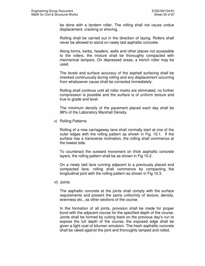
Engineering Group Document E/GD/09/104/A1 M&W for Civil & Structural Works Sheet 35 of 67
be done with a tandem roller. The rolling shall not cause undue displacement, cracking or shoving.
Rolling shall be carried out in the direction of laying. Rollers shall
never be allowed to stand on newly laid asphaltic concrete. Along forms, kerbs, headers, walls and other places not accessible
to the rollers, the mixture shall be thoroughly compacted with mechanical tampers. On depressed areas, a trench roller may be used.
The levels and surface accuracy of the asphalt surfacing shall be
checked continuously during rolling and any displacement occurring from whatsoever cause shall be corrected immediately.
Rolling shall continue until all roller marks are eliminated, no further
compression is possible and the surface is of uniform texture and true to grade and level.
The minimum density of the pavement placed each day shall be
98% of the Laboratory Marshall Density. v) Rolling Patterns Rolling of a new carriageway lane shall normally start at one of the
outer edges with the rolling pattern as shown in Fig. 10.1. If the surface has a transverse inclination, the rolling shall commence at the lowest side.
To counteract the outward movement on thick asphaltic concrete
layers, the rolling pattern shall be as shown in Fig 10.2. On a newly laid lane running adjacent to a previously placed and
compacted lane, rolling shall commence by compacting the longitudinal joint with the rolling pattern as shown in Fig 10.3.
vi) Joints The asphaltic concrete at the joints shall comply with the surface
requirements and present the same uniformity of texture, density, evenness etc., as other sections of the course.
In the formation of all joints, provision shall be made for proper
bond with the adjacent course for the specified depth of the course. Joints shall be formed by cutting back on the previous day’s run to expose the full depth of the course; the exposed edge shall be given a light coat of bitumen emulsion. The fresh asphaltic concrete shall be raked against the joint and thoroughly tamped and rolled.
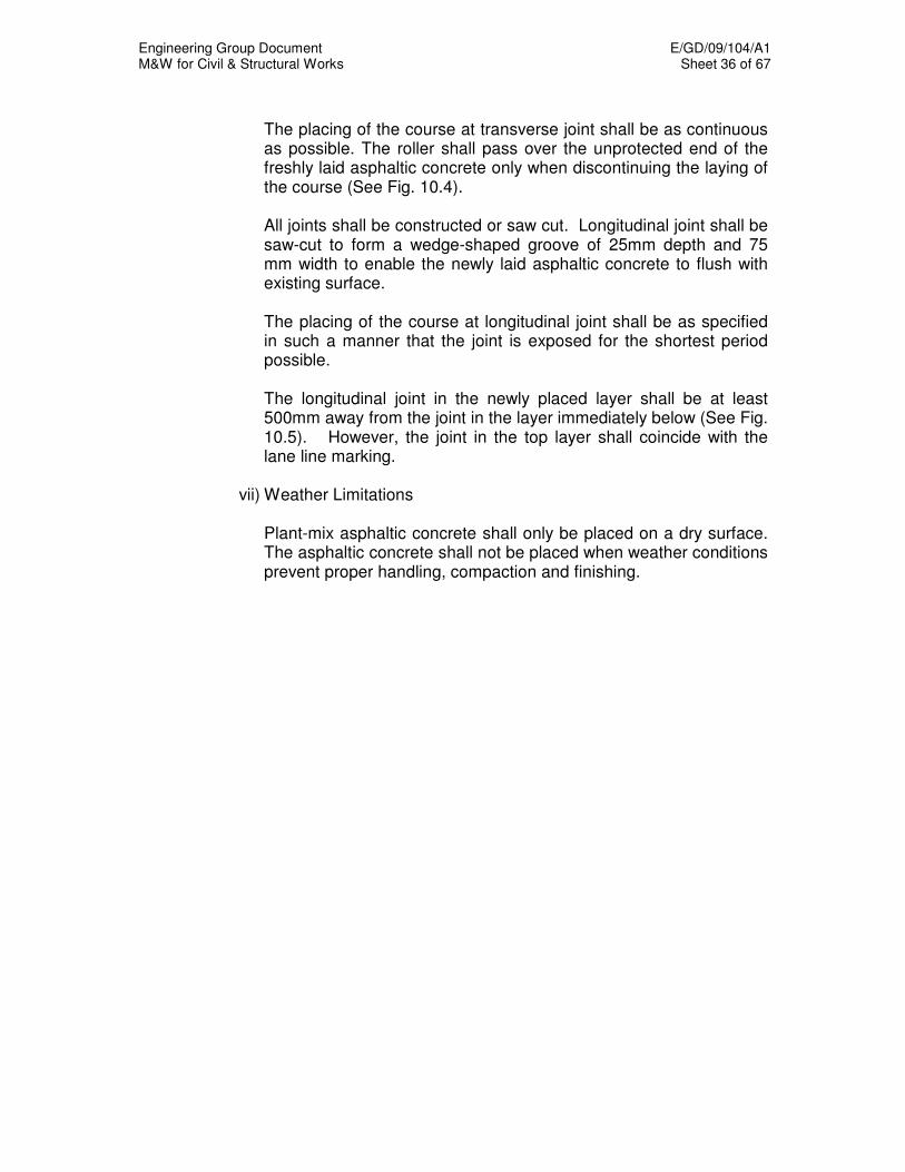
Engineering Group Document E/GD/09/104/A1 M&W for Civil & Structural Works Sheet 36 of 67
The placing of the course at transverse joint shall be as continuous
as possible. The roller shall pass over the unprotected end of the freshly laid asphaltic concrete only when discontinuing the laying of the course (See Fig. 10.4).
All joints shall be constructed or saw cut. Longitudinal joint shall be
saw-cut to form a wedge-shaped groove of 25mm depth and 75 mm width to enable the newly laid asphaltic concrete to flush with existing surface.
The placing of the course at longitudinal joint shall be as specified
in such a manner that the joint is exposed for the shortest period possible.
The longitudinal joint in the newly placed layer shall be at least
500mm away from the joint in the layer immediately below (See Fig. 10.5). However, the joint in the top layer shall coincide with the lane line marking.
vii) Weather Limitations Plant-mix asphaltic concrete shall only be placed on a dry surface.
The asphaltic concrete shall not be placed when weather conditions prevent proper handling, compaction and finishing.
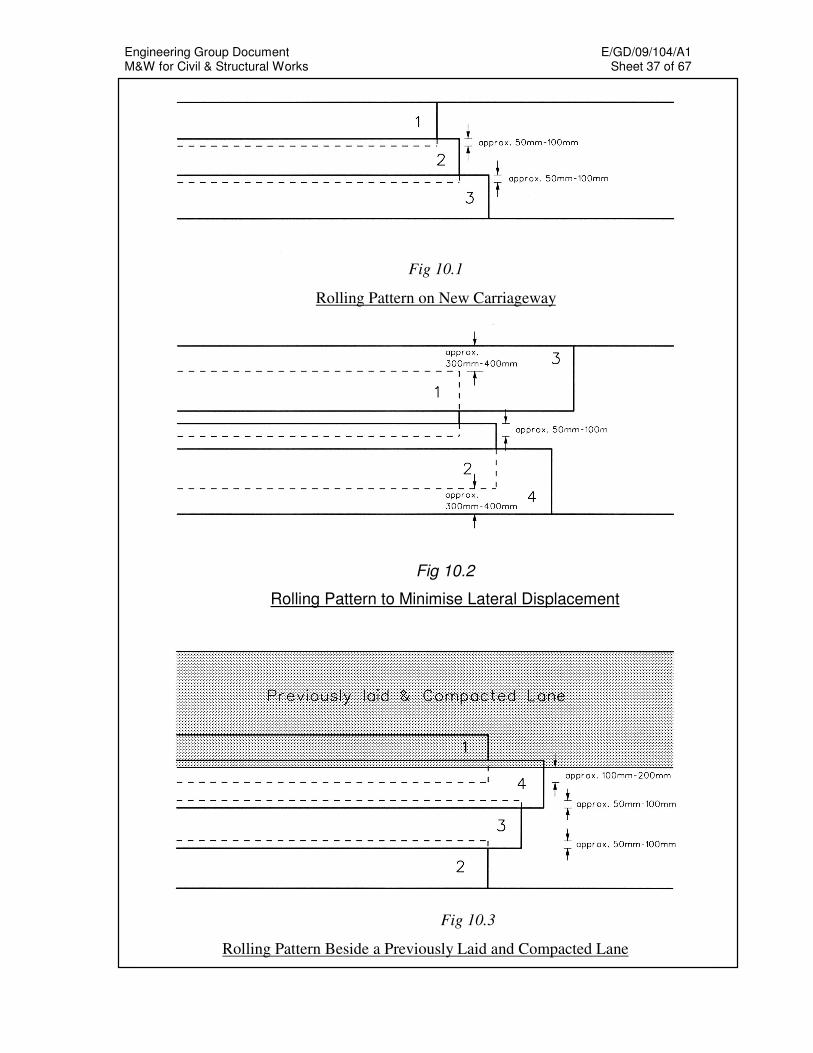
Engineering Group Document E/GD/09/104/A1 M&W for Civil & Structural Works Sheet 37 of 67
Fig 10.1
Rolling Pattern on New Carriageway
Fig 10.2
Rolling Pattern to Minimise Lateral Displacement
Fig 10.3
Rolling Pattern Beside a Previously Laid and Compacted Lane
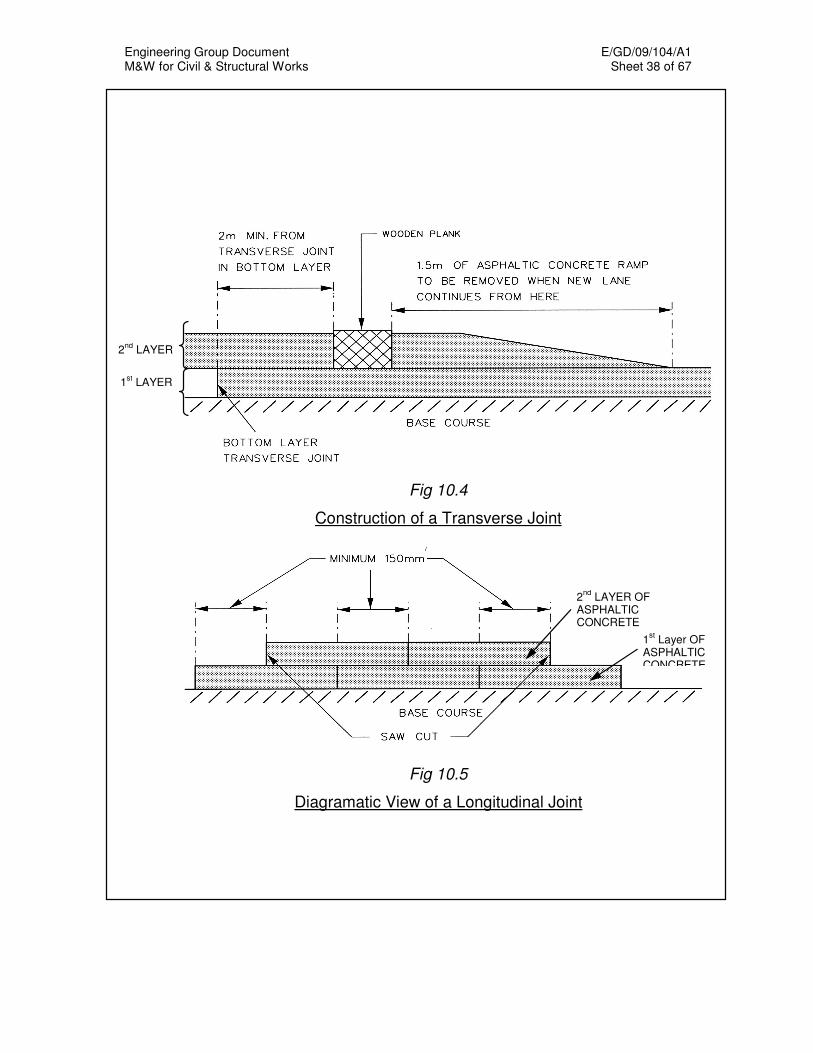
Engineering Group Document E/GD/09/104/A1 M&W for Civil & Structural Works Sheet 38 of 67
2nd
LAYER
1st LAYER
Fig 10.4
Construction of a Transverse Joint
Fig 10.5
Diagramatic View of a Longitudinal Joint
1st Layer OF
ASPHALTIC CONCRETE
2nd
LAYER OF ASPHALTIC CONCRETE
Engineering Group Document E/GD/09/104/A1 M&W for Civil & Structural Works Sheet 39 of 67
f) Quality Control
i) Sampling and Testing of Asphaltic Concrete. The contractor shall supply all necessary labour and approved
equipment for the purpose of extracting core samples. Samples shall be neatly cut with a core drill or other similar equipment. No less than 6 no. of 100mm diameter core samples shall be extracted at each site. The locations of the coring shall be determined by the Engineer on a random basis. The core samples extracted from the sites not later than 7 days after the laying of the asphaltic concrete.
The Contractor shall supply and finish new material to backfill voids
left by sampling. The Contractor shall give one day’s notice to the Engineer of his
intention to carry out any tests on the samples taken. The field density of the asphaltic concrete shall be determined from
the core samples extracted from the site. All core samples shall have a field density of 98% or more of the Laboratory Marshall Density. The Engineer shall reject the works on sites where the field densities are less than 98% of the Laboratory Marshall Density.
The Laboratory Marshall Density is the average of the laboratory
density of all Marshall samples (75 blow on both sides of the samples) taken over the period of laying of asphaltic concrete at the corresponding site.
In lieu of the core method of density determination, testing for
acceptance may be accomplished with nuclear device in accordance with ASTM D2950.
The following procedures shall be followed:
• Before nuclear test may be used, a test section shall be constructed for correlation purposes. The minimum density of cored samples from the test section shall be at least 98% of the Laboratory Marshall Density. If the minimum density is less than 98%, a new test section shall be constructed for correlation.
• Ten (10) nuclear density tests shall be taken at the test section for correlation purposes. The average of the 10 nuclear density tests shall be taken as the acceptable field density.
A new test section may also be ordered by the Engineer when:
• A change in the material or job mix formula is made.
Engineering Group Document E/GD/09/104/A1 M&W for Civil & Structural Works Sheet 40 of 67
• Ten days of production have been accepted without construction of a new test section.
• There is reason to believe that the test section density is not representative of the material being placed.
ii) Site Control At all times during the course of the paving works, the Engineer
shall at his discretion, carry out tests to check that the finished surface conforms with the specified crown and grade. Any variation shall be immediately corrected by removal or addition of materials and continuous rolling.
After the completion of final rolling, the evenness of the course
shall again be tested, humps or depressions exceeding the specified tolerances shall be immediately corrected by removing the defective work and replacing with new material.
iii) Laboratory Tests Asphaltic concrete sampled for laboratory specimens shall be
chosen on a random basis. Samples shall be taken at the rate of one per 50 tonnes of asphaltic
concrete laid and at least 3 samples shall be taken at each site in a day. These samples shall be marked with the mix type, date laid, location and plant identification. The Engineer shall select from all the samples taken on the particular day for each mix type per plant, a minimum of 3 and a maximum of 10 samples to be tested.
The contractor shall supply all necessary labour, equipment and
approved containers to collect samples of asphaltic concrete at site and deliver the samples to the accredited laboratory for testing. The results obtained for each mix type for each day shall be deemed to be representative of all the sites for that day. When the work for a site is done over a period longer than one day, the results from all relevant days shall be used.
The samples shall be tested for bitumen content, gradation,
Marshall Density, Marshall stability, stiffness ratio, percentage voids in mix and percentage of aggregates voids filled with bitumen binder.
Similarly, the Engineer shall select 3 samples per day for each mix
type per plant for the determination of the Marshall Laboratory Density and other Marshall properties. The average Marshall Laboratory Density per mix type shall be used for the comparison with the field density.
Engineering Group Document E/GD/09/104/A1 M&W for Civil & Structural Works Sheet 41 of 67
10.3.4 W3B(20R) and B1(30R) Asphaltic Concrete with Reclaimed Asphalt Pavement 10.3.4.1 Materials a) Reclaimed Asphalt Pavement
Reclaimed asphalt pavement (RAP) is the term given to processed milled waste. Milled waste is generated when asphalt pavements are removed for reconstruction, resurfacing, or to obtain access to buried utilities. When milled waste is properly processed, RAP shall consist of high-quality, well-graded aggregates coated by asphalt binder. Not more than 20% and 30% RAP shall be allowed for use in asphaltic concrete for the asphaltic wearing course and base course, respectively.
b) Processed Aggregates
Processed aggregates with residual bitumen removed from RAP shall comply with Clause 10.3.3.1(a).
c) Aggregates
Aggregates shall consist of crushed stone or crushed gravel with or without sand or other inert finely divided mineral aggregate.
d) Bitumen
Residual bitumen of RAP coated on processed aggregates shall be analysed for its suitability before mixing with asphaltic concrete mix. The method of analysis shall be submitted to the Engineer for approval.
e) Admixture
No admixture (rejuvenator) shall be allowed in the asphaltic concrete with RAP.
10.3.4.2 Mix Design
The contractor shall propose the job mix design with the target binder content and aggregate grading for the Engineer’s approval. The contractor shall carry out tests to determine and propose the final bitumen content. The target bitumen content for asphaltic concrete with RAP mixes shall conform to the requirements of Table 10.7. The job mix formula shall be determined in 2 stages as follows:-
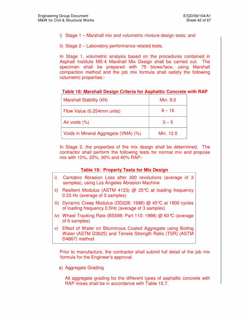
Engineering Group Document E/GD/09/104/A1 M&W for Civil & Structural Works Sheet 42 of 67
i) Stage 1 – Marshall mix and volumetric mixture design tests; and
ii) Stage 2 – Laboratory performance related tests.
In Stage 1, volumetric analysis based on the procedures contained in Asphalt Institute MS-4 Marshall Mix Design shall be carried out. The specimen shall be prepared with 75 blows/face, using Marshall compaction method and the job mix formula shall satisfy the following volumetric properties:-
Table 18: Marshall Design Criteria for Asphaltic Concrete with RAP
Marshall Stability (kN) Min. 9.0
Flow Value (0.254mm units) 8 – 16
Air voids (%) 3 – 5
Voids in Mineral Aggregate (VMA) (%) Min. 12.0
In Stage 2, the properties of the mix design shall be determined. The contractor shall perform the following tests for normal mix and propose mix with 10%, 20%, 30% and 40% RAP:-
Table 19: Property Tests for Mix Design
i) Cantabro Abrasion Loss after 300 revolutions (average of 3 samples), using Los Angeles Abrasion Machine
ii) Resilient Modulus (ASTM 4123) @ 25°C at loading frequency 0.33 Hz (average of 3 samples)
iii) Dynamic Creep Modulus (DD226: 1996) @ 45°C at 1800 cycles of loading frequency 0.5Hz (average of 3 samples)
iv) Wheel Tracking Rate (BS598: Part 110: 1998) @ 60°C (average of 6 samples)
v) Effect of Water on Bituminous Coated Aggregate using Boiling Water (ASTM D3625) and Tensile Strength Ratio (TSR) (ASTM D4867) method
Prior to manufacture, the contractor shall submit full detail of the job mix formula for the Engineer’s approval.
a) Aggregate Grading
All aggregate grading for the different types of asphaltic concrete with RAP mixes shall be in accordance with Table 10.7.

Engineering Group Document E/GD/09/104/A1 M&W for Civil & Structural Works Sheet 43 of 67
b) Marshall Design Criteria
All samples obtained from asphaltic concrete with RAP tested for Marshall Design Criteria shall conform to the requirements of Table 10.8.
c) Criteria for Acceptance
Where these samples fail to satisfy the acceptance criteria in Table 10.9, asphaltic concrete with RAP mixes laid and represented by the unsatisfactory samples shall be rejected by the Engineer.
In addition, fresh bitumen used for the mixing of asphaltic concrete with
RAP shall be tested for compliance with Table 10.6.
10.3.4.3 Manufacture Manufacturing of asphaltic concrete with RAP shall include, but not limited to, the crushing of milled waste, screening of processed aggregates, analysis of residual bitumen coated on processed aggregates.
a) Processing and Analysis of Milled Waste
Milled waste must be processed to the desired aggregate gradation using approved equipment consisting of crushers or granulators, screening units, conveyors, and stacker. The processed milled waste (i.e. RAP) must be analysed to determine their suitability for use and the analysis shall include, but not limited to, the characteristic of the residual bitumen and processed aggregates
b) Stockpiling Material contamination shall be prevented during processing and stockpiling operations. RAP shall be stored in stockpiles on smooth surfaces free of debris and organic material. RAP stockpiles shall only consist of homogeneous RAP.
c) Batching Plant for Asphaltic Concrete with RAP
The Contractor shall furnish the Engineer in advance with full details of all batching plants to be used for asphaltic concrete with RAP, in accordance with the format shown in Table 10.17c.
The batching plant shall have an average output capacity of not less than 100 tonnes/hr.

Engineering Group Document E/GD/09/104/A1 M&W for Civil & Structural Works Sheet 44 of 67
Before the batching plant can be used, the measuring, recording mechanism and temperature control gauges shall be tested by Singapore Accreditation Council or other internationally recognized bodies in accordance to the manufacturer's specification. The Contractor shall submit the calibration certificates to the Engineer.
The Engineer shall have access at all times to the plant, storage yard and other facilities for processing the material. He shall be at liberty to take samples of materials, as he deems necessary.
Table 10.20: Format for Submitting Details of Asphaltic concrete with RAP Batching Plant
Asphalt Mixing Plant
1 Type, model and manufacturer of plant for production of premix
2 Age of plant
*Batch / Continuous
Feed Manufacture ______________________
Model ________________
Capacity Rating ______________________
_________________ years
3 Average output capacity in tonnes per hour 4 Location of plant 5 State whether the location of plant is
approved by the relevant authority and its permanency
6 State the number of personnel and years of
experience for the following personnel:
• Plant Operator
• Technician
• Asphalt Specialist
• Qualified Engineer
• Technical Manager
______________ tonnes/hr ______________________
Yes / No
_____ pax _______ yrs/mths
_____ pax _______ yrs/mths _____ pax _______ yrs/mths _____ pax _______ yrs/mths _____ pax _______ yrs/mths
Engineering Group Document E/GD/09/104/A1 M&W for Civil & Structural Works Sheet 45 of 67
d) Heating of Bitumen Binder
The binder shall be separately heated in approved heating tanks. Thermometers shall be provided both in the storage tanks and also on the mixing platform. The temperature dials shall be readily accessible and kept clean at all times.
The bitumen of 60/70 penetration grade shall be heated to 150 - 165°C.
The difference in temperature between the aggregate and the bitumen shall not exceed 15°C.
e) Drying and Heating of Aggregates
The plant shall include at least two cold-hoppers for coarse and fine aggregates. When two or more fine aggregates are being incorporated in the mixture, a separate hopper shall be provided for each. The feed gates or other devices provided for controlling the output from each hopper shall be capable of accurate adjustment to ensure uniform rate of feed.
When loading the cold hoppers, care shall be taken to avoid segregation of the aggregates and they shall be kept sufficiently full to allow an even flow through the feed gates.
Aggregates shall be thoroughly dry before mixing, and the contractor shall carry out moisture test at least once a week on a sample from each hot bin to check the effectiveness of the drying processes. If at any time the tests indicate that the drying facilities are inadequate, mixing shall cease until the contractor has augmented his drying capability to the satisfaction of the Engineer. All drying plant shall be equipped with efficient dust extractors.
A suitable thermometer for measuring the temperature of the aggregates shall be fitted at the drier discharge and shall be maintained in good working order.
f) Mixing Temperature
The Contractor shall ensure that the batching of the aggregates, RAP and new bitumen, the dry and wet mixing time, the temperatures for the heating of the aggregates and the mix shall be accurately controlled to produce a uniformly coated and acceptable mix within the limits specified.
The aggregates shall be heated to between 150°C and 170°C. The aggregates used to mix and heat up cold RAP in the heating drum shall not be overheated to avoid overheating of aggregates and bitumen.

Engineering Group Document E/GD/09/104/A1 M&W for Civil & Structural Works Sheet 46 of 67
Extracted dust shall be automatically fed back into the dry or wet admixtures. When it satisfies the specified requirements for filler, it shall be weighed into the mixture as a separate proportion. All mixing plant shall incorporate means of access to each hot bin / storage bin to enable samples to be taken. Overheating of the aggregate, RAP or binder shall be prohibited and rejected mixture shall not be used. During mixing, the hot aggregates and RAP shall be thoroughly and intimately mixed together with filler and bitumen binder in the correct proportion until every particle of aggregates is completely coated. The total mixing time may only be reduced if the Engineer is satisfied that thorough mixing can be achieved in less time. After mixing, the asphaltic concrete with RAP shall then be discharged directly into a truck and properly covered with a canvas cover. The temperature of the mix at this stage shall be between 140ºC to 160ºC. The asphaltic concrete with RAP shall be rejected at the Contractor’s own cost if the temperature of the hot mix measured at the truck is above 160ºC or below 140ºC.
10.3.4.4 Asphalt Laying
The requirements of asphalt laying shall be in accordance with Clause 10.3.3.5.
10.3.4.5 Quality Control and Quality Assurance
Prior to the proposed use of asphaltic concrete with RAP, the contractor shall submit the following for the Engineer’s approval:-
i) Facility plan and details of the plant that produces asphaltic
concrete with RAP;
ii) Details of manufacturing process and control, and its associated Quality Management System;
iii) Quality Control and Quality Assurance (QA/QC) plan to
demonstrate the elimination of sub-standard materials or poor workmanship and to ensure compliance with the specifications; and
iv) Resources and capabilities in performing in-house mix design,
equipped with the necessary laboratory equipment for the QA/QC tests listed in this specification.
The QA/QC plan shall also include appropriate provisions for the Engineer to perform spot tests during the initial assessment of production control and also during routine inspection by spot samples from the running production.
Engineering Group Document E/GD/09/104/A1 M&W for Civil & Structural Works Sheet 47 of 67
The inspection and QA/QC plan must be certified by an independent accreditation body such as Singapore Accreditation Council (SAC) prior to manufacturing of asphaltic concrete with RAP and such accreditation must be carried out annually.
All relevant tests shall be carried out in independent laboratories accredited by the SAC (under SAC-SINGLAS).
The Authority may appoint an independent pavement specialist from a relevant recognised professional body or academic institution to audit the manufacturing process and control of asphaltic concrete with RAP and the QA/QC plan.
The Engineer’s approval shall be valid for the duration of the
project/contract or one year whichever is earlier. 10.4 RIGID PAVEMENT 10.4.1 General The Contractor shall comply with all the requirements of Chapter 11 of the
Materials & Workmanship Specification on Concrete and Reinforcement and details shown in the "Standard Details of Road Elements" unless otherwise specified in this Chapter.
10.4.2 Materials
a) Tie Bars Tie bars shall be deformed bars of high yield stress complying with the
requirements of SS 2. b) Dowel Bars Dowel bars shall be plain mild steel bars complying with the requirements
of SS 2 and shall be free from burring or other deformation restricting slippage in the concrete. Before delivery to the construction site, a minimum of two-thirds of the length of each dowel bar shall be painted with one coat of rust preventative paint.
c) Joint Filler Joint filler shall be a resin-impregnated fibreboard or self-expanding cork
complying with the requirements of ASTM D1752. d) Joint Sealers Joint sealers shall comply with the following specifications:
Engineering Group Document E/GD/09/104/A1 M&W for Civil & Structural Works Sheet 48 of 67
Hot-poured Sealant BS 2499 Cold-poured Sealant BS 5212 Preformed Compression Seal ASTM D2628
e) Curing Materials
Curing materials shall comply with the following specifications: Liquid membrane-forming compounds ASTM C309, Type 2 Polyethylene film ASTM C171 White burlap-polyethylene sheeting ASTM C171
10.4.3 Construction
a) Equipment A paver may be used subject to the approval of the Engineer. b) Placing Concrete Concrete shall be placed in a continuous operation without cold joint and
thoroughly compacted by means of vibrators. c) Protection of Pavement The Contractor shall have available at all time materials for the protection
of the edges and surfaces of the unhardened concrete. Such protective materials shall consist of rolled polyethylene sheet at least 0.1mm thick of sufficient length and width to cover the plastic concrete slab and any edges.
d) Joints Longitudinal and transverse joints shall be constructed as indicated on
the drawings. All joints shall be constructed true to line to an accuracy of 13mm with their faces perpendicular to the surface of the pavement. The surface across the joints shall be tested with a 3m straight edge as the joints are finished and any irregularities in excess of 6mm shall be corrected before the concrete has hardened. When required, keyways shall be accurately formed with a template of metal or wood. Transverse joints shall be at right angles to the centreline of the pavement and shall extend to the full width of the slab. The transverse joints in succeeding lanes shall be placed in line with similar joints in the first lane.
Tie bars shall be placed at right angles to concrete slab, unless
otherwise specified. Tie bars shall not be painted, greased, or enclosed in sleeves.
Engineering Group Document E/GD/09/104/A1 M&W for Civil & Structural Works Sheet 49 of 67
e) Final Strike-off, Compaction and Finishing
i) Sequence The sequence of operations shall be the strike-off and compaction,
floating and removal of laitance, straightening, and final surface finish. The addition of superficial water to the surface of the concrete to assist in finishing operations shall generally not be permitted.
ii) Finishing at Joints After the concrete has been placed and vibrated adjacent to the
joints, the finishing machine shall be operated in a manner to avoid damage or misalignment of joints.
iii) Strike-off The strike-off of screed for the surface shall be at least 500mm longer
than the maximum width of the slab to be struck off. A suitable vibrator shall be used for compaction.
iv) Straight Edge Testing and Surface Correction After the pavement has been struck off and compaction and while the
concrete is still plastic, it shall be tested for trueness with a 3 m straight edge swung from handles 1m longer than one-half the width of the slab. Straight edge testing and surface corrections shall continue until the entire surface is found to be free from observable departures from the straight edge and until the slab conforms to the required grade and cross section. The use of long-handled wood floats shall be confined to a minimum; they may be used only in emergencies and in areas not accessible to finishing equipment.
f) Surface Texture The surface of the pavement shall be broom finish. It shall be applied
when the water sheen has practically disappeared. The equipment shall operate transversely across the pavement surface,
providing corrugations that are uniform in appearance and approximately 2mm in depth.
g) Alignment and Surface Tolerances The pavement shall be constructed to the following tolerances:
• Lateral deviation from established alignment of the pavement edge shall not exceed ±30mm in any lane.
Engineering Group Document E/GD/09/104/A1 M&W for Civil & Structural Works Sheet 50 of 67
• Vertical deviation from established grade shall not exceed ±6 mm at any point. However, the combination of permitted tolerances in different pavement levels shall not result in a reduction of the thickness of the concrete slab by more than 5 mm from that specified.
• Surface smoothness deviation shall not exceed 6mm from a 3m straight-edge placed in any direction including placement along and across any pavement joint or edge.
Where any specified tolerances are exceeded, the pavement section,
which is out of tolerance, shall be removed and replaced unless the Engineer directs otherwise. Any section so removed shall not be less than 3 m in length for the full width of the lane involved. When it is necessary to remove and replace a section of pavement, any remaining portion of the slab adjacent to the joints that is less than 3 m in length shall also be removed and replaced.
h) Curing Immediately after the finishing operations have been completed and
marring of the concrete will not occur, the entire surface of the newly placed concrete shall be cured in accordance with one of the methods below. The concrete shall not be left exposed for more than half an hour during the curing period. The curing shall be maintained for 72 hours after the concrete has been placed.
i) Impervious Membrane Method The entire surface of the pavement shall be sprayed uniformly with an
approved curing compound immediately after the finishing of the surface and before the set of the concrete has taken place. The curing compound shall not be applied during rainfall. Curing compound shall be applied by mechanical sprayers.
ii) Polyethylene Film The top surface and sides of the pavement shall be entirely covered
with polyethylene sheeting. The units shall be lapped at least 450mm. The sheeting shall be placed and weighed to cause it to remain in contact with the surface covered. The sheeting shall have dimensions that will extend at least twice the thickness of the pavement beyond the edges of the pavement.
iii) White Burlap-Polyethylene Sheet The surface of the pavement shall be entirely covered with the
sheeting. The sheeting used shall be such length (or width) that it will extend at least twice the thickness of the pavement beyond the edges of the slab. The sheeting shall be placed and weighed to remain in
Engineering Group Document E/GD/09/104/A1 M&W for Civil & Structural Works Sheet 51 of 67
contact with the surface covered, and the covering shall be maintained fully wetted.
i) Removing Forms Unless otherwise specified, forms shall not be removed from freshly
placed concrete until it has set for at least 12 hours, except where auxiliary forms are used temporarily in widened areas. Forms shall be removed carefully to avoid damage to the pavement. After the forms have been removed, the sides of the slab shall be cured. Honeycombed areas shall be removed and replaced. Any area or section so removed shall not be less than 3 m in length for the full width of the lane involved. When it is necessary to remove and replace a section of pavement, any remaining portion of the slab adjacent to the joints that is less than 3 m in length shall also be removed and replaced.
j) Sealing Joints Unless otherwise specified, the joints in the pavement shall be sealed
immediately following the curing period or as soon thereafter as weather conditions permit.
10.5 PAVEMENT MARKINGS 10.5.1 Temporary Pavement Marking
Temporary pavement marking shall only be used for traffic diversion scheme of less than 3 months duration. The marking material shall comply with the requirements in SS 221. a) Method of Application
All pavement line painting and pavement marking which include pedestrian crossing, box junctions, continuous broken lines, numerals, bus zones, arrows, lettering, etc. must be fully mechanised and drawn or spray painted by pavement line painting machine. Paint shall not be applied by brushes to pavement lines and markings. No painting shall be done on surfaces, which are wet or damp from rain, dew or any other causes until they have been properly dried.
b) Quality Control
i) Wet Film Thickness All paints for pavement marking shall be supplied ready-mixed by
the manufacturer and no thinning shall be permitted.
Engineering Group Document E/GD/09/104/A1 M&W for Civil & Structural Works Sheet 52 of 67
All paints for pavement marking shall be applied to wet film thickness of 375 microns to a tolerance of 50 microns.
ii) Maintenance Period The Contractor shall maintain all pavement lines and markings
executed by him for three months and repaint the pavement lines and markings when the degree of visibility of the painting has decreased by more than 50% during the maintenance period.
10.5.2 Thermoplastic Pavement Marking Thermoplastic pavement marking shall be used for permanent pavement
marking and traffic diversion scheme of more than 3 months duration.
a) Material
i) Thermoplastic Pavement Marking The thermoplastic material to be used shall comply with SS 498.
And the density of the thermoplastic material shall not be less than 1.65 kg/l.
ii) Profile Thermoplastic Longitudinal Linemarking The drawing of profile thermoplastic longitudinal Linemarking is as
shown in Figure 10.6. The material shall be a thermoplastic compound conforming to the requirements of SS 498 except that the material shall have the following characteristics:
• Softening point when measured in accordance with SS 498 shall be
greater than 100°C.
• Viscosity when measured in accordance with the Brookefield
method shall be 440 Poise at 160°C and 320 Poise at 180°C.
• Flow resistance when measured in accordance with SS 498 shall be 2% maximum.
• Indentation shall be 1mm maximum when using a 100g indenter for
1 hour at 70°C.
• Sample shall have no crack under impact test when using a Falling
Ball method at 0°C.
• Abrasion resistance shall not be more than 1% weight loss when measured for 100 revolutions of modified aggregate abrasion machine.

Engineering Group Document E/GD/09/104/A1 M&W for Civil & Structural Works Sheet 53 of 67
• Luminance factor (laboratory) shall have minimum 80 for high grade.
• Skid resistance (laboratory) shall have minimum 50 when measured with the TRRL Pendulum as specified in SS 498.
• Reflectorization with class A solid glass beads as specified in SS 498 must be used to improve the visibility of road markings. The glass beads shall be applied to the completed profile pavement marking immediately after application of the thermoplastic material.
Fig 10.6 Profile Thermoplastic Longitudinal Linemarking
b) Retroreflectometer for Measuring Retroreflectiveness Road Marking The Contractor shall submit the specification of the portable
retroreflectometer for the acceptance of the Engineer before measurement is conducted.
Direction of Traffic
50 50
70
70
70
300
300
2 6
(Measurements in mm)
Engineering Group Document E/GD/09/104/A1 M&W for Civil & Structural Works Sheet 54 of 67
The measuring geometry must be as follows; Entrance Angle: 86.5° Observer Angle: 85.0°
c) Application Technique
The application of road marking materials to road surfaces shall
comply with Part 3 of SS 498. d) Quality Control
i) Sampling
Samples shall be taken:
• at the manufacturer’s plant or upon delivery from the manufacturer, and
• after it has been re-melted by the pavement application contractor.
Three containers shall be selected at random from any consignment or batch at the manufacturer’s depot or received from the manufacturer, three containers shall be selected at random. The materials from the three containers shall be uniform in texture and colour. A material of not less than 2 kg shall be taken near the centre of each of the three containers. The materials shall then be combined in a clean container clearly labelled with the relevant details, e.g. supplier, batch number, type and date. Heat shall not be applied at any stage of the sampling process. Three portions each of not less than 2 kg shall be taken from the outlet of the laying apparatus at agreed intervals during application of the marking material. The first and last 5% of the charge shall not be used. Where the material is being screeded by hand the portions may be taken from the outlet of the melter. The portions shall be combined in a clean container clearly labelled with the relevant details, e.g. contractor, type of material, site and date. No heat shall be applied at any stage of the sampling process once the material has issued from the melting or laying apparatus.
ii) Testing
All material properties and their related test methods shall conform
to SS 498 and carried out by an accredited laboratory.

Engineering Group Document E/GD/09/104/A1 M&W for Civil & Structural Works Sheet 55 of 67
The Contractor shall submit test reports of the samples to the
Engineer for acceptance. iii) Information of Product to be Supplied by Manufacturer
The Contractor shall obtain from the manufacturer the following information on the thermoplastic material:
• Maximum safe heating temperature of the material
• Temperature range of application for screed laying
• Flash point of the material
• Composition of the mixture
• Road Trial Certificate in accordance to Part 2 of SS498
iv) Protection of New Road Marking
The Contractor shall protect the new markings until the material has set. All materials laid and subsequently rendered unsuitable shall be rejected by the Engineer.
10.6 ROAD AND RELATED FACILITIES CONSTRUCTION 10.6.1 Setting Out, Survey and Levelling The Contractor shall employ a licensed surveyor throughout the Contract
Period for all survey related works inclusive of the setting out for the following:
• the centreline of the road reserve/pavement • the limits of the road reserve • the inner edge and outer edge of all slip roads
• the positions of culverts, bridges/underpasses all structures • all drainworks • kerblines of carriageway; and
• others works not limited to the above
All setting out works shall be demarcated on site by masonry nails or wooden pegs at 30m intervals along the straight and 5m to 30m intervals along curves in accordance with Table 10.18.
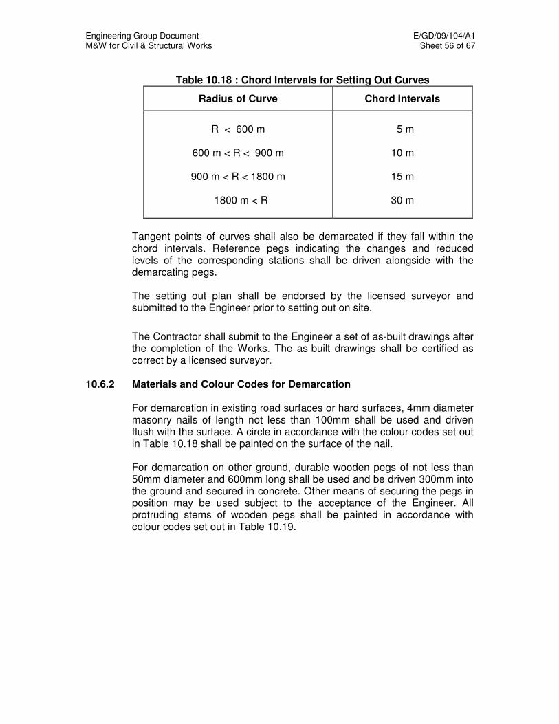
Engineering Group Document E/GD/09/104/A1 M&W for Civil & Structural Works Sheet 56 of 67
Table 10.18 : Chord Intervals for Setting Out Curves
Radius of Curve Chord Intervals
R < 600 m
600 m < R < 900 m
900 m < R < 1800 m
1800 m < R
5 m
10 m
15 m
30 m
Tangent points of curves shall also be demarcated if they fall within the chord intervals. Reference pegs indicating the changes and reduced levels of the corresponding stations shall be driven alongside with the demarcating pegs. The setting out plan shall be endorsed by the licensed surveyor and submitted to the Engineer prior to setting out on site. The Contractor shall submit to the Engineer a set of as-built drawings after the completion of the Works. The as-built drawings shall be certified as correct by a licensed surveyor.
10.6.2 Materials and Colour Codes for Demarcation For demarcation in existing road surfaces or hard surfaces, 4mm diameter
masonry nails of length not less than 100mm shall be used and driven flush with the surface. A circle in accordance with the colour codes set out in Table 10.18 shall be painted on the surface of the nail.
For demarcation on other ground, durable wooden pegs of not less than
50mm diameter and 600mm long shall be used and be driven 300mm into the ground and secured in concrete. Other means of securing the pegs in position may be used subject to the acceptance of the Engineer. All protruding stems of wooden pegs shall be painted in accordance with colour codes set out in Table 10.19.
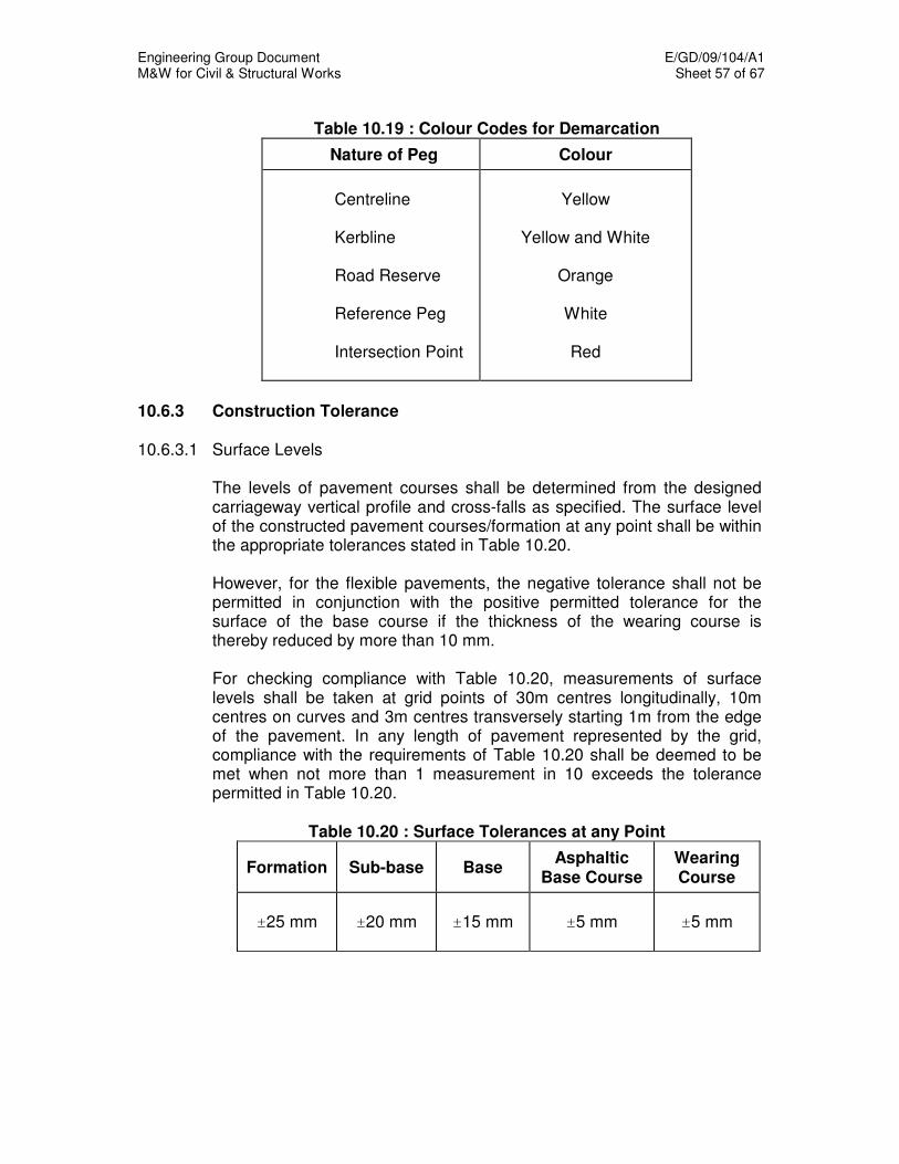
Engineering Group Document E/GD/09/104/A1 M&W for Civil & Structural Works Sheet 57 of 67
Table 10.19 : Colour Codes for Demarcation
Nature of Peg Colour
Centreline Kerbline Road Reserve Reference Peg Intersection Point
Yellow
Yellow and White
Orange
White
Red
10.6.3 Construction Tolerance 10.6.3.1 Surface Levels The levels of pavement courses shall be determined from the designed
carriageway vertical profile and cross-falls as specified. The surface level of the constructed pavement courses/formation at any point shall be within the appropriate tolerances stated in Table 10.20.
However, for the flexible pavements, the negative tolerance shall not be
permitted in conjunction with the positive permitted tolerance for the surface of the base course if the thickness of the wearing course is thereby reduced by more than 10 mm.
For checking compliance with Table 10.20, measurements of surface
levels shall be taken at grid points of 30m centres longitudinally, 10m centres on curves and 3m centres transversely starting 1m from the edge of the pavement. In any length of pavement represented by the grid, compliance with the requirements of Table 10.20 shall be deemed to be met when not more than 1 measurement in 10 exceeds the tolerance permitted in Table 10.20.
Table 10.20 : Surface Tolerances at any Point
Formation Sub-base Base Asphaltic
Base Course Wearing Course
±25 mm
±20 mm
±15 mm
±5 mm
±5 mm

Engineering Group Document E/GD/09/104/A1 M&W for Civil & Structural Works Sheet 58 of 67
10.6.3.2 Longitudinal Profile Measurement Longitudinal profile of the top surface shall be determined by the
computed International Roughness Index (IRI) in accordance with ASTM E1926. Measurements shall be carried in accordance with ASTM E950 or ASTM E1364.
The acceptable IRI values are as follow :
i) IRI less than or equal to 2mm/m for Expressway and Semi-Expressway;
ii) IRI less than or equal to 4mm/m for other roads.
10.6.3.3 Horizontal Alignment The edges of the carriageways (kerb lines) shall be constructed to a
tolerance of ±25 mm. The setting out of the horizontal alignment shall be
within the minimum accuracy of 1 in 5000. 10.6.4 Rectification of Levels
Where the construction of the pavement course exceeds the tolerance, the Contractor shall determine the full extent of the area. The Contractor shall make good the surface of the pavement course to the acceptance of the Engineer before proceeding to the next layer. a) Formation or Subgrade Level If the surface is too high it shall be re-trimmed and re-compacted in
accordance with Chapter 4, Earthworks. If the surface is too low the deficiency shall be corrected by the addition of fresh suitable material of the same classification laid and compacted.
b) Sub-base and Base Where these consist of unbound material, the top layer shall be
scarified and reshaped with added materials as necessary and re-compacted. Unless otherwise accepted by Engineer, the area treated shall not be less than 30m long and 3m wide.
c) Asphaltic Base Course and Wearing Course The full depth of the asphaltic base course or wearing course shall be
removed and replaced with fresh material laid and compacted.

Engineering Group Document E/GD/09/104/A1 M&W for Civil & Structural Works Sheet 59 of 67
For rectification of the asphaltic base course or wearing course, the area treated shall be at least 5m or 15m long respectively and it shall be not less than one lane wide.
10.6.5 Vehicular Traffic on Pavement
Restrictions on use are: a) Concrete Slabs Vehicular traffic is permitted when the concrete compressive strength
exceeds 25 N/mm² or 3 days whichever is greater.
b) Asphaltic Base Course Vehicular traffic is permitted 9 hours after initial laying of the asphaltic
base course. However, it may be reduced subject to the acceptance of the Engineer but must not be less than 3 hours.
The Contractor shall be responsible for rectification of all defects in the pavement arising from traffic use.
10.6.6 Vehicular Impact Guardrail 10.6.6.1 Materials The beam shall be fabricated from sheet steel. The beam section shall be
as shown on the Drawings. Bolts and nuts shall be manufactured from carbon steel and shall conform to the requirements of ASTM A307 Grade A and ASTM A563 Grade A respectively.
10.6.6.2 Mechanical Properties
The beam metal shall conform to the following tensile requirements: • Minimum yield point - 345 N/mm²
• Minimum tensile strength - 483 N/mm²
• Elongation on a 50mm test gauge length of beam element shall not be
less than 12%
The test specimens shall be prepared and tested as specified in ASTM A653. If galvanised test specimens are used, the correction for thickness shall be 0.15mm. All bolts shall have a tensile strength of at least 414N/mm² tested as
specified in ASTM A307.
Engineering Group Document E/GD/09/104/A1 M&W for Civil & Structural Works Sheet 60 of 67
10.6.6.3 Thickness of Metal The base metal of beam or sheet shall be of nominal thickness of 3mm.
The nominal thickness for the galvanised beam or sheet shall be 3.15mm with a tolerance for under specified thickness of 0.25mm. For fabricated beams, thickness measurements shall be made for tangent portions of the cross section.
10.6.6.4 Dimensions of Beam The beam shall be shaped from sheets and shall have a projected width
of not less than 305mm and a depth of not less than 76mm. The sheets used have a nominal width of 483mm. Tolerance from the nominal width of minus 3.2mm will be permissible.
The effective length of the beam element shall in general be 3810mm long
with provision of mounting of post at 1905mm centres. 10.6.6.5 Connections and Splices The beam element shall be spliced by lapping in the direction of traffic.
The splice shall be fastened with eight bolts and shall not be less than 318mm in length. All connections or splices shall be formed with oval shoulder button-headed bolts to minimise projections on the roadside of the guardrails. All bolt heads shall be embossed with the manufacturer’s brand.
10.6.6.6 Terminal Sections The terminal sections shall be fabricated from sheet steel manufactured
from the same type of metal and having the same gauge thickness and galvanised in the same manner as the beam elements and also to the same mechanical properties.
10.6.6.7 Galvanising The beam shall be hot-dipped galvanised after fabrication. The zinc used
for the coating shall be as prescribed in ASTM B6 or AASHTO M120 and shall be at least equal to the grade designated as “Prime Western”. The total weight of zinc coating on both sides of beam shall not be less than 1220 g/m² of the sheet when tested in accordance with AASHTO
T65 or ASTM A653 Triple Spot Test. No test specimen shall have a coating weight of less than 1100 g/m² for any Single Spot Test.
The sheets or beams shall be of prime finish that is free from injurious defects such as blister, flux and uncoated spots.
Engineering Group Document E/GD/09/104/A1 M&W for Civil & Structural Works Sheet 61 of 67
The coating shall be smooth, free of beading or sharp projections along the edges and shall adhere tenaciously to the surface of the metal. The adherence of the zinc coating to the surface of the base metal shall be determined by use of a stout knife applied with considerable pressure in a manner tending to remove a portion of the coating by paring or whittling, and it shall not be possible to peel any portion of the coating so as to expose the base metal. All bolts, nuts and washers for use with guardrail shall be hot-dipped galvanised as specified in ASTM A153 or AASHTO M232 or sheradized as specified in BS 7371, Part 8 (1998).
10.6.6.8 Fabrication of Beam Elements and Terminal Sections The beam elements and terminal sections shall be formed to proper shape and dimensions complying with AASHTO M180. They shall be punched and drilled with holes for mounting and splicing and ready for assembly before being delivered to the site. No punching, drilling, cutting or welding shall be permitted in the field unless accepted by the Engineer for special reasons and for sampling. The beam shall be uniform section, straight or curved as required and so designed that when installed it will not hold water. The edges shall be rolled or rounded to eliminate sharp edges. Warped, kinked or bent sections shall be rejected. Beams to be erected on a radius of less than 45m shall be shop-curved.
10.6.6.9 Marking Each beam element shall be identified by the brand name of manufacture. Markings shall not be placed at such a location on the beam section that they will be obscured after erection or in a manner that the brand will be conspicuous to any traffic. Marking material shall be able to resist obliteration during storage, transportation and erection. Marking for end sections and back-up plates may be on durable tags securely attached to each section or bundle.
10.6.6.10 Testing
The manufacturer or fabricator shall ensure that the material produced complies with all specification requirements. A copy of manufacturer’s certificate shall be supplied to the Engineer upon request.
However, the Engineer may still select one piece of guardrail, backing plate and terminal section from each lot of 200 pieces for testing to determine that specification requirements have been complied with. If the lot is less than 200 pieces, the Engineer may select one piece each of

Engineering Group Document E/GD/09/104/A1 M&W for Civil & Structural Works Sheet 62 of 67
guardrail, backing plate and terminate section for testing. If one piece fails to meet the requirements, then two additional pieces shall be tested. If either one of these pieces fail to conform, the lot represented by these samples shall be rejected. If in subsequent actual field use, there is detection of non-compliance with the requirements of this Specification as determined by random sampling by the Engineer, the material of the lot will be rejected.
10.6.6.11 Posts All guardrail posts and spacers, unless otherwise specified shall comply to
Chapter 12 on Structural Steelwork. 10.6.6.12 Installation The guardrail shall be erected after placing of the asphaltic base course or
asphaltic wearing course unless otherwise accepted by the Engineer. The guardrail shall be erected to the alignment, as shown on the
Drawings. Adjacent rails shall be connected by lap joints, using suitable bolts, nuts and washers as shown on the Drawings.
Assembly shall proceed in the direction of traffic flow in order to avoid
vehicles striking rail ends. 10.7 FOOTPATH EXPANSION JOINT FILLER
Footpath expansion joint filler shall be an approved proprietary type complying with the following properties: a) Rot proof and resistant to bacteriological attack. b) Non water absorbent. c) Non-staining when in contact with concrete, mortar or granite slabs. d) Bitumen free. e) Non-extruding under load. f) Resilient, giving a compression of at least 50% under a load of
0.5N/mm2.
g) Recovery under compression shall exceed 80% when subject to 50%
compression for a period of 24 hours.

Engineering Group Document E/GD/09/104/A1 M&W for Civil & Structural Works Sheet 63 of 67
For joints up to and including 25 mm, the material shall be in a single
piece with thickness to conform to the width of the joint. For joints over 25 mm, the material may be in one or two layers with total thickness to conform to the width of joint.
10.8 RETROREFLECTIVE SHEETING The retroreflective sheeting used shall be suitable for the manufacturing of
traffic signs, directional signs, street name signs and miscellaneous signs. 10.8.1 Material The sheeting material to be used shall comply generally with ASTM
D4956-2004 Type I to IX. 10.8.2 Test of Reflective Sheeting and Test Report The test methods for reflective sheetings shall conform with ASTM D4956-
2004. The test reports shall cover all colours of sheeting called for in this
contract and together with 1 square foot sample for each colour of sheetings and/or materials shall be submitted to the Engineer for approval before installation.
10.8.3 Warranty for the Reflective Sheetings and Vinyl Films
The Contractor shall jointly with the manufacturer issue a warranty to cover the quality and performance of the reflective sheetings and vinyl films in respect of colour fungus resistance and adhesion for the warranty period. The form of warranty shall be in accordance with the format shown in the General Specification.
The different sheeting and their period of Guarantee from completion of whole of the works are listed below:
i) Type I and II - 3 years
ii) Type III to VI - 7 years
iii) Type VII to IX - 7 years
For reflectivity sheetings, the guarantee shall also cover its retroreflective elements for the guaranteed period. The manufacturer is required to satisfy the SO by performing with an approved retroreflectometer that the reflective sheeting comply with the Federal Test Method 370 / ASTM E810 to check the submitted test result at the commencement of the Contract.
Engineering Group Document E/GD/09/104/A1 M&W for Civil & Structural Works Sheet 64 of 67
The minimum coefficient of retroreflective values of the reflective sheeting at end of warranted life shall comply with ASTM D4956-2004.
The testing with the retroreflectometer has to be performed by the manufacturer to check every batch of reflective sheeting which is supplied to his Contractor to ensure that they comply with the minimum requirement as well as to check the performance of the reflective sheetings used on the signs at the end of the guaranteed period.
The readings recorded shall achieved in respect of retroreflective element and colour.
The sheeting manufacturer shall replace the signs that could not meet the aforesaid Clause within seven (7) days from being informed by the SO.
All completed signs shall have a coloured sticker at its rear/underside/post indicating the month and year of manufacture which shall constitute the start of the warranty. Stickers of various colours will be use to indicate the different year of manufacture as shown in Appendix 1.
The Engineer and the sheeting manufacturer shall have access to the Contractor’s sign fabrication workshop to perform quality audit as necessary at all reasonable times.
10.8.4 Transparent Process Inks These inks are to be used in conjunction with the reflective sheeting in the
manufacturing of road signs. The ink shall be transparent in nature such that light can pass and be
reflected through it when painted on the surface of the reflective sheeting. It shall have comparable reflectivity to that of the reflective sheeting and
good reflection shall be cast back to the light source in similar range of angles of that sheeting.
It shall have high durability and resistance to fading under local weather
conditions, heat and humidity. It shall not crack, delaminate and peel after being applied on the reflective sheeting and used on the roads. The expected life of the ink shall not be less than the life of the sheeting.
A Test Report from an accredited laboratory shall be submitted to the
Engineer for acceptance before the transparent process ink is used.
Engineering Group Document E/GD/09/104/A1 M&W for Civil & Structural Works Sheet 65 of 67
The Test Report shall include at least the following information; The degree of transparency, the intensity of reflection when used in
conjunction with different colours of sheeting, durability under weather, heat and moisture effects, stability of colour etc.
The contractor shall jointly with the manufacturer issue a warranty to cover
the quality and performance in terms of reflectivity, colour, cracking and peeling of the transparent process inks. The period of Guarantee from completion of whole of the works for the transparent process ink are listed below:
i) Type I and II sheeting - 3 years ii) Type III to VI sheeting - 7 years iii) Type VII to IX sheeting - 7 years
10.9 RAISED PAVEMENT MARKERS 10.9.1 Construction
a) The lens shroud or the main body shall be of die-cast aluminium material. When installed they shall not project over the road surface by more than 25mm.
b) The body shall have all rounded edges and all angles to the horizontal
shall not exceed 60 degrees. c) The marker shall be of anchored type. The length of the stem shall be
between 50mm and 80mm long. d) The filling compound shall be of epoxy based adhesive.
10.9.2 Reflection
a) All markers shall be reflectorised markers. b) The reflector or the reflective device shall be permanently attached to
the body of the marker. c) The reflector shall be mounted in a protected recess of the marker. d) The reflectors shall be a series of small bi-convex glass lenses
arranged in strips with minimum 30 lens per face, or with a retro-reflective area not less than 25cm
2 per face.
Engineering Group Document E/GD/09/104/A1 M&W for Civil & Structural Works Sheet 66 of 67
10.9.3 Effectiveness The reflectors shall work by the principle of the incident light of the vehicle
headlights being reflected back to the source. 10.9.4 Installation
a) The installed marker shall be able to resist twisting, forward or sideward movement.
b) If any of the markers are dislodged during the first year, the contractor
shall replace them with the new ones. c) Traffic shall be allowed to go over the installed area within half an hour.
10.10 PRECAST CONCRETE KERBS AND DIVIDERS All precast concrete kerbs and dividers shall conform to the drawings and
requirements in SS 214.

Engineering Group Document E/GD/09/104/A1 M&W for Civil & Structural Works Sheet 67 of 67

Engineering Group Document E/GD/09/104/A1 M&W for Civil & Structural Works Sheet 1 of 48
CHAPTER 11
CONCRETE AND REINFORCEMENT 11.1 CONCRETE MIX 11.1.1 General The Contractor shall select the mix proportions and constituents in order to
satisfy the requirements of the Contract. Unless otherwise accepted by the Engineer, only designed mix shall be
used for all Works. 11.2 CONSTITUENT MATERIALS OF CONCRETE The Contractor shall supply to the Engineer, test results to demonstrate
compliance with the Standards.
11.2.1 Cement The cement to be used in the Works shall be Portland Cement to Class
42.5 as specified in SS26. Any proposal by the Contractor to partially substitute any cementitious materials, such as fly ash, ground granulated blast furnace slag or silica fume, for Portland cement shall be submitted for Engineer’s acceptance. The Contractor shall not change the cement brand or source of any approved cementitious material until he has obtained permission in writing from the Engineer prior to the change.
Pulverised Fuel Ash (PFA) and Ground Granulated Blast Furnace slag
(GGBS) mineral admixtures, where proposed to be used shall comply with the requirements of BS3892 and BS 6699 respectively
11.2.2 Aggregates All aggregates for use in concrete shall comply with SS31. Aggregates used
shall not be alkali reactive. Marine aggregates shall not be used.
Sampling and testing of all aggregates shall be carried out in accordance with the requirements of SS73. Mortar Bar tests shall be conducted to determine whether or not the aggregate is alkali-reactive.
Grading tests shall be carried out before the start of any production and at
weekly intervals when concrete is being produced. The Engineer reserves the right to draw samples of aggregates from any stockpile at any time for testing and the Contractor shall deliver the samples at his cost to any approved accredited laboratory. Aggregates whose grading, are found to fall outside the accepted zone shall be rejected.

Engineering Group Document E/GD/09/104/A1 M&W for Civil & Structural Works Sheet 2 of 48
11.2.2.1 Washed Copper Slag (WCS) and Recycled Aggregates
The use of washed copper slag (WCS) or recycled concrete aggregates shall only be allowed for non-structural elements as listed below. The WCS and recycled aggregates are used to partially replace normal aggregates in eco-concrete (supplied by BCA's approved RMCs).
List of Non-structural Elements
• Non-suspended slab excluding rigid pavement, approach slab and floor slab within a building or at apron and entrance area
• Road kerbs and drop inlet chambers • Open channel up to type C7 size • Blinding concrete • Haunching to utility services
Quality control and testing plan for eco-concrete shall be the same as normal concrete. All tests shall be carried out by laboratories independent from the concrete supplier.
11.2.3 Water Water shall be clean and free from harmful matter. If taken from a source
other than the Public Utilities Board, water shall be tested in accordance with BS 3148 and shall be subject to the Engineer's acceptance.
11.2.4 Admixtures All admixtures for use in concrete shall comply with SS320. Information to
be submitted for the Engineer's acceptance before any admixture is supplied shall be in accordance with SS320.
All admixtures shall be used strictly in accordance with the manufacturer's
instructions. All concrete used to fill temporary construction access holes (for example, in viaduct girders) shall be provided with an accepted shrinkage compensating admixture.
11.3 REQUIREMENTS FOR DESIGN MIX
In designed mixes, the strength shall be the main criterion specified, with compliance to minimum and maximum cement content, and maximum water/cement ratio. Mix design shall be based on a target mean strength not less than the specified characteristic strength plus 7N/mm
2.
Design of mix shall ensure no segregation, no excessive bleeding and ability to achieve specified surface finish.
Engineering Group Document E/GD/09/104/A1 M&W for Civil & Structural Works Sheet 3 of 48
The Contractor shall submit the appropriate information as described in SS289 Part 3 for the Engineer's acceptance before any concrete is supplied. Trial mixes of three separate batches of concrete shall be made using accepted materials and produced under full-scale production conditions. Sampling and testing shall be in accordance with Cl. 4.4 of SS289, Part 3. The workability of each of the three trial batches shall be determined and six cubes made from each batch. Three from each set of six shall be tested at an age of 28 days, and three at an earlier age accepted by the Engineer. The average strength of the nine cubes tested at 28 days shall exceed the specified characteristic strength by at least 10N/mm
2.
During production the Engineer may require additional trial mixes to be made before a substantial change is made in the materials or in the proportions of the materials to be used. They need not be carried out when adjustments are made to the mix proportions in accordance with Cl.11.8.
PFA content shall be between 25% and 40% by mass of the specified minimum cementitious content.
GGBS content shall content shall be between 70% and 80% by mass of the specified minimum cementitious content.
11.4 REQUIREMENTS FOR FRESH CONCRETE
The workability of the fresh concrete shall be such that the concrete is suitable for the conditions of handling, placing and compaction. The temperature of concrete and the plant shall not exceed 32°C unless accepted by the Engineer.
11.5 REQUIREMENTS FOR HARDENED CONCRETE
The grade of concrete to be used in the Works shall be as defined by the characteristic strength in N/mm
2 at 28 days as determined from test cubes.
The total chloride content of the concrete mix arising from the aggregate
together with that from any admixtures and any other source shall not in any circumstances exceed the limits in Table 4 of SS289 Part 1. When required by the Engineer, the Contractor shall carry out tests to demonstrate that these limits are not exceeded.
The levels of acid-soluble sulphates (as SO3) shall generally not exceed the
following limits, which are indicative for the individual constituents of the mix and are subject to the overriding maxima specified for the total mix:
Engineering Group Document E/GD/09/104/A1 M&W for Civil & Structural Works Sheet 4 of 48
Coarse aggregate 0.4% by weight Fine aggregate 0.4% by weight Fresh water 500 mg/l
The total estimated sulphate content as SO3 of any mix, including that present in the cement shall not exceed 3.7% by weight of cement in the mix.
When directed by the engineer, tests in accordance with BS 1881: Part 124 shall be made on hardened concrete to determine the total sulphate content as SO3 of any mix. The concrete shall be rejected if the sulphate content exceed 4% by weight of cement in the mix.
11.6 PRODUCTION OF CONCRETE 11.6.1 General The supervision employed shall be such as to ensure the required standard
of control over materials and workmanship. The Engineer shall be given all reasonable opportunity and facility to inspect the materials and manufacture of concrete and to take any samples or to make any tests, which he may require.
Separate storage facilities with adequate provision for drainage shall be
provided for each different size of aggregates used. Aggregates shall be handled and stored so as to minimise segregation and
contamination. All aggregate deliveries shall be inspected and the grading and silt content of each size of aggregate from each pit, quarry or other source of supply shall be determined at least once weekly.
The quantity of cement, the quantity of fine aggregate and the quantities of
the various sizes of coarse aggregate shall be measured by weight. A separate weighing device shall be provided for weighing the cement.
Alternatively, the cement may be measured by using a whole number of bags in each batch.
The amount of water shall be measured, by volume or by weight. Any solid
admixtures to be added shall be measured by weight but liquid or paste admixtures may be measured by volume or weight.
The batch weights of aggregate shall be adjusted to allow for a moisture
content typical of the aggregates being used. The accuracy of the measuring equipment shall be within ± 3% of the
quantity of cement, water or total aggregates being measured and within ± 5% of the quantity of any admixture being used. All measuring equipment shall be maintained in a clean, serviceable condition.
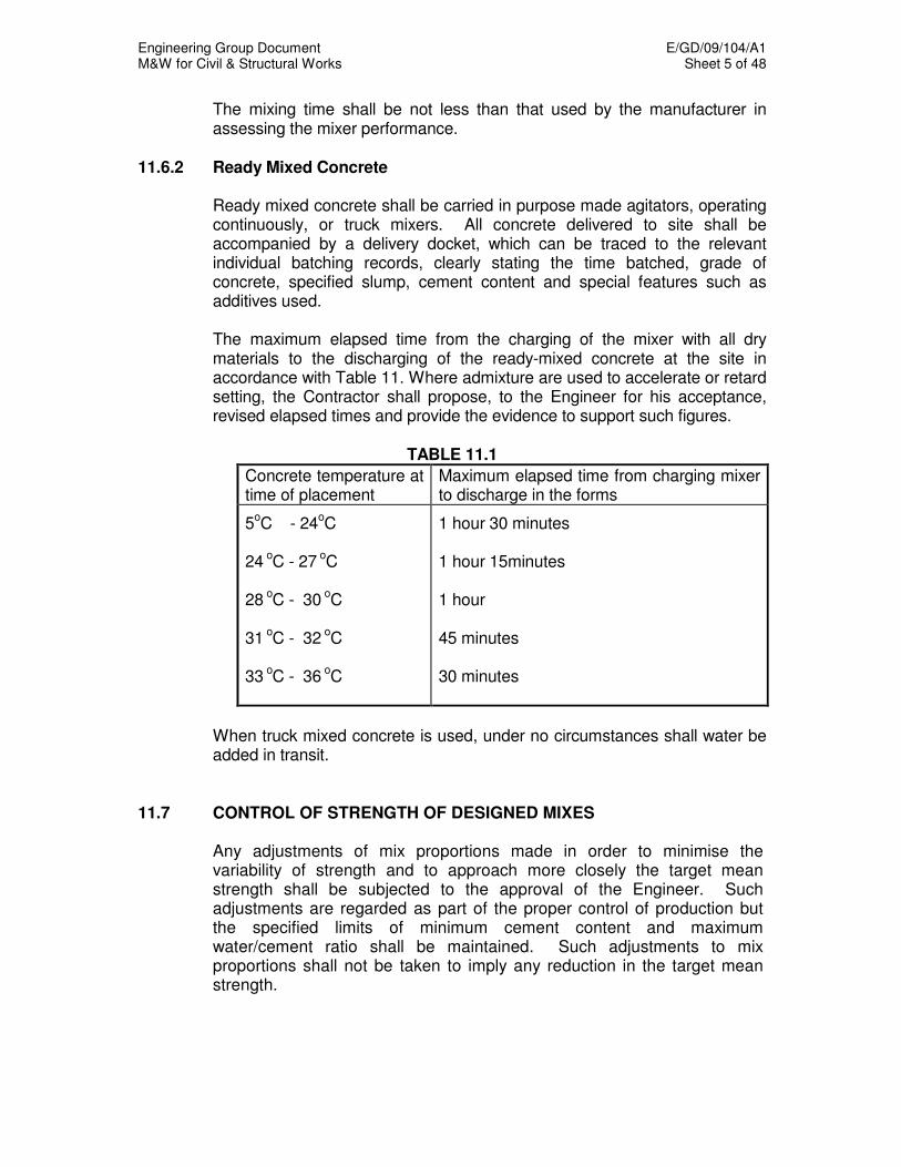
Engineering Group Document E/GD/09/104/A1 M&W for Civil & Structural Works Sheet 5 of 48
The mixing time shall be not less than that used by the manufacturer in assessing the mixer performance.
11.6.2 Ready Mixed Concrete Ready mixed concrete shall be carried in purpose made agitators, operating
continuously, or truck mixers. All concrete delivered to site shall be accompanied by a delivery docket, which can be traced to the relevant individual batching records, clearly stating the time batched, grade of concrete, specified slump, cement content and special features such as additives used.
The maximum elapsed time from the charging of the mixer with all dry
materials to the discharging of the ready-mixed concrete at the site in accordance with Table 11. Where admixture are used to accelerate or retard setting, the Contractor shall propose, to the Engineer for his acceptance, revised elapsed times and provide the evidence to support such figures.
TABLE 11.1
Concrete temperature at time of placement
Maximum elapsed time from charging mixer to discharge in the forms
5oC - 24
oC
24
oC - 27
oC
28
oC - 30
oC
31
oC - 32
oC
33
oC - 36
oC
1 hour 30 minutes 1 hour 15minutes 1 hour 45 minutes 30 minutes
When truck mixed concrete is used, under no circumstances shall water be
added in transit. 11.7 CONTROL OF STRENGTH OF DESIGNED MIXES Any adjustments of mix proportions made in order to minimise the
variability of strength and to approach more closely the target mean strength shall be subjected to the approval of the Engineer. Such adjustments are regarded as part of the proper control of production but the specified limits of minimum cement content and maximum water/cement ratio shall be maintained. Such adjustments to mix proportions shall not be taken to imply any reduction in the target mean strength.
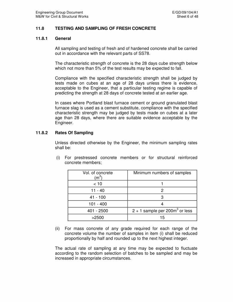
Engineering Group Document E/GD/09/104/A1 M&W for Civil & Structural Works Sheet 6 of 48
11.8 TESTING AND SAMPLING OF FRESH CONCRETE 11.8.1 General All sampling and testing of fresh and of hardened concrete shall be carried
out in accordance with the relevant parts of SS78. The characteristic strength of concrete is the 28 days cube strength below
which not more than 5% of the test results may be expected to fall. Compliance with the specified characteristic strength shall be judged by
tests made on cubes at an age of 28 days unless there is evidence, acceptable to the Engineer, that a particular testing regime is capable of predicting the strength at 28 days of concrete tested at an earlier age.
In cases where Portland blast furnace cement or ground granulated blast
furnace slag is used as a cement substitute, compliance with the specified characteristic strength may be judged by tests made on cubes at a later age than 28 days, where there are suitable evidence acceptable by the Engineer.
11.8.2 Rates Of Sampling Unless directed otherwise by the Engineer, the minimum sampling rates
shall be:
(i) For prestressed concrete members or for structural reinforced concrete members;
Vol. of concrete (m
3)
Minimum numbers of samples
< 10 1
11 - 40 2
41 - 100 3
101 - 400 4
401 - 2500 2 + 1 sample per 200m3 or less
>2500 15
(ii) For mass concrete of any grade required for each range of the concrete volume the number of samples in item (i) shall be reduced proportionally by half and rounded up to the next highest integer.
The actual rate of sampling at any time may be expected to fluctuate
according to the random selection of batches to be sampled and may be increased in appropriate circumstances.
Engineering Group Document E/GD/09/104/A1 M&W for Civil & Structural Works Sheet 7 of 48
A batch shall be defined as the quantity of concrete mixed in one cycle of
operations of a batch mixer or the quantity of concrete delivered to site ready mixed in a vehicle.
Where there are more than one plant supply, the sampling rate shall be
proportionally distributed among the suppliers based on the volume of concrete generated from the supplier's plant.
An early assessment shall be made of the 28-day strength using a method
acceptable to the Engineer. The mix shall be adjusted as necessary to achieve the specific characteristic strength.
11.8.3 Testing Plan A sample shall be taken from a randomly selected batch of concrete. The
samples, whenever practicable, shall be taken at the point of discharge from the mixer or in the case of ready mix concrete at the point of discharge from the delivery vehicle. Cubes shall be prepared and cured as follows:
(i) For reinforced concrete and mass concrete, 4 cubes shall be made
from each sample of concrete taken; 2 cubes for test at 7 days and 2 cubes for test at 28 days. The actual section of the structure represented by test result shall be included in the test report.
(ii) For prestressed concrete, the following conditions shall apply:
- At least two cubes shall be tested prior to each stage of prestressing work to ensure that the minimum transfer strength for each stage has been attained.
- At 28 days, at least two further cubes shall be tested to determine
the characteristic strength of the sample. The average of the cube results tested at 28 days for any given sample
shall be the test result. When the difference in strength between the two cubes divided by their
mean exceeds 15%, the test result shall be deemed invalid. 11.8.4 Compliance Requirements Compliance with the specified characteristic strength is attained if the
average strength determined from each group of four consecutive test results and if each individual test result complies with the appropriate limits of Table 1 of SS289: Part 4.
Where concrete for the project is supplied by more than one source, the
compliance requirement shall be determined based on the groups of results analysed separately from each source.
Engineering Group Document E/GD/09/104/A1 M&W for Civil & Structural Works Sheet 8 of 48
Where less than four test results are available for a particular grade of concrete from a particular source, compliance shall be based on groups of two or three test results (the higher available number shall be used) in accordance with Table 1 of SS289: Part 4.
11.8.5 Quantity of Concrete Represented by Strength Test Results
(i) The quantity of concrete represented by any group of four
consecutive test results shall be the quantity represented by the first to the last test samples in the group.
(ii) When individual test result fails to comply with the requirements of Table 1 of SS289: Part 4, only the quantity of concrete represented by the particular sample shall be at risk.
(iii) The quantity of concrete considered to be represented by a particular sample shall be the actual sampling rate, i.e. if for a particular pour of Q m
3, t samples are taken, then the quantity of concrete represented
by a particular sample shall be (Q/t) m3.
11.8.6 Action on Non-Compliance
In the event of non-compliance with the testing plan outlined in Cl.11.8.3, the following actions shall be taken:
The Contractor shall before proceeding with further concreting, submit to
the Engineer for acceptance, details of the action proposed to ensure that the concrete still to be placed in the Works will comply with the requirements of the Specification. All such works shall be at the contractor's expense and no extension of time will be granted.
The Contractor shall propose what action is to be taken with regard to the
defective concrete already placed. In estimating the quality of the sub-standard concrete and in determining the action to be taken, the Contractor shall establish the following, (i) The actual section of the structure represented by the test cube(s). (ii) The possible influence of any reduction in concrete quality on the
strength and durability of this section of the structure The Engineer may require tests on the hardened concrete in the structure, such as the taking of cored samples at the contractor's expense.
11.8.7 Cement Content and Free Water/Cement Ratio The maximum cement content shall be limited by the need for
temperature control when early thermal and drying shrinkage are potential causes of cracking. For Ordinary Portland Cement (OPC), the maximum cement content shall not exceed 400kg/m
3.
Engineering Group Document E/GD/09/104/A1 M&W for Civil & Structural Works Sheet 9 of 48
The maximum free water cement ratio shall not exceed 0.45. The above represent the maximum typical requirements. The design shall
allow for more onerous exposure conditions and/or aggressive chemical and physical conditions where such conditions are likely to be present.
11.8.8 Percentage Air Content The percentage air content determined from individual samples taken at
the point of placing the concrete and representative of any given batch of concrete shall comply with SS289 Part 4.
11.8.9 Workability of Concrete The workability of concrete shall be within the limits, specified in SS289
Part 4.
11.9 SURFACE FINISH OF CONCRETE 11.9.1 General For all visible concrete, uniformity of colour and texture are important and
all materials shall be obtained from single consistent source. The aggregates shall be durable and free of any impurities, which may cause staining. The mix proportions and the grading, particularly of the fine aggregate, shall be maintained constant. Any partial replacement of individual plywood sheets or sections of timber in large panels shall be avoided.
Where formwork ties or other embedded ferrous metal parts are built into
the concrete, the whole or part of any such supports shall be capable of removal so that any part that remain embedded in the concrete shall be at less 50mm away from the surface. Holes left after the removal of such parts shall be neatly filled with well-rammed, colour matched, dry-pack mortar.
Release agents for formwork shall be carefully chosen for the particular
conditions to ensure the compatibility of the release agent with the finish. Release agents shall be applied evenly and contact with reinforcement and shall be avoided. Where a concrete surface is to be permanently exposed only one release agent shall be used throughout the entire area.
For all concrete visible to the Engineer, appearance is important, and
curing methods and conditions including the time of removal of formwork shall receive careful consideration. Components that are intended to have the same surface finish shall receive the same treatment and the same curing regime. Where the surface is to receive an applied finish, the Contractor shall ensure the compatibility of any sprayed on curing membrane with the finish to be applied.
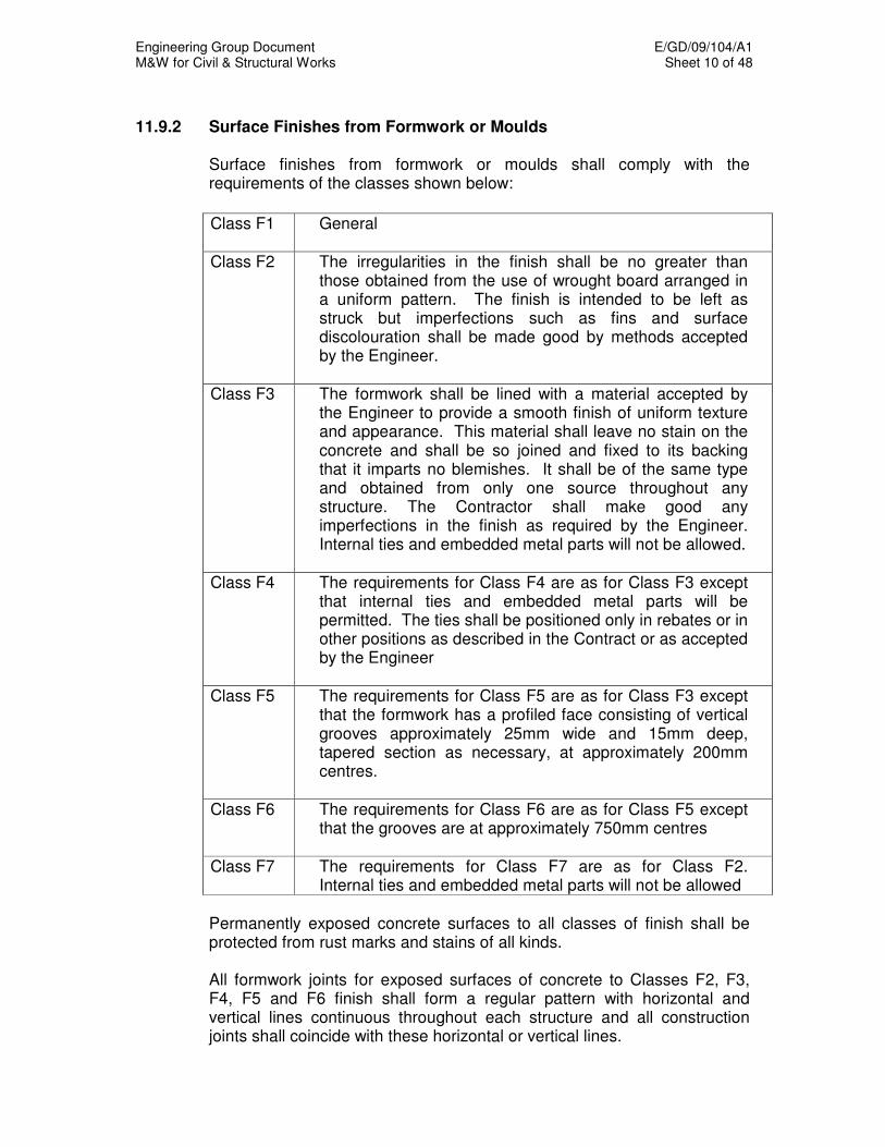
Engineering Group Document E/GD/09/104/A1 M&W for Civil & Structural Works Sheet 10 of 48
11.9.2 Surface Finishes from Formwork or Moulds
Surface finishes from formwork or moulds shall comply with the requirements of the classes shown below:
Class F1 General
Class F2 The irregularities in the finish shall be no greater than those obtained from the use of wrought board arranged in a uniform pattern. The finish is intended to be left as struck but imperfections such as fins and surface discolouration shall be made good by methods accepted by the Engineer.
Class F3 The formwork shall be lined with a material accepted by the Engineer to provide a smooth finish of uniform texture and appearance. This material shall leave no stain on the concrete and shall be so joined and fixed to its backing that it imparts no blemishes. It shall be of the same type and obtained from only one source throughout any structure. The Contractor shall make good any imperfections in the finish as required by the Engineer. Internal ties and embedded metal parts will not be allowed.
Class F4 The requirements for Class F4 are as for Class F3 except that internal ties and embedded metal parts will be permitted. The ties shall be positioned only in rebates or in other positions as described in the Contract or as accepted by the Engineer
Class F5 The requirements for Class F5 are as for Class F3 except that the formwork has a profiled face consisting of vertical grooves approximately 25mm wide and 15mm deep, tapered section as necessary, at approximately 200mm centres.
Class F6 The requirements for Class F6 are as for Class F5 except that the grooves are at approximately 750mm centres
Class F7 The requirements for Class F7 are as for Class F2. Internal ties and embedded metal parts will not be allowed
Permanently exposed concrete surfaces to all classes of finish shall be protected from rust marks and stains of all kinds. All formwork joints for exposed surfaces of concrete to Classes F2, F3, F4, F5 and F6 finish shall form a regular pattern with horizontal and vertical lines continuous throughout each structure and all construction joints shall coincide with these horizontal or vertical lines.
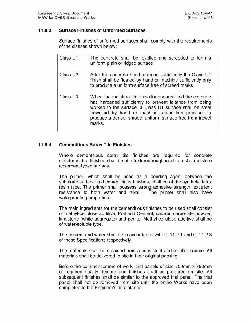
Engineering Group Document E/GD/09/104/A1 M&W for Civil & Structural Works Sheet 11 of 48
11.9.3 Surface Finishes of Unformed Surfaces Surface finishes of unformed surfaces shall comply with the requirements
of the classes shown below:
Class U1 The concrete shall be levelled and screeded to form a uniform plain or ridged surface
Class U2 After the concrete has hardened sufficiently the Class U1 finish shall be floated by hand or machine sufficiently only to produce a uniform surface free of screed marks
Class U3 When the moisture film has disappeared and the concrete has hardened sufficiently to prevent laitance from being worked to the surface, a Class U1 surface shall be steel trowelled by hand or machine under firm pressure to produce a dense, smooth uniform surface free from trowel marks.
11.9.4 Cementitious Spray Tile Finishes Where cementitious spray tile finishes are required for concrete
structures, the finishes shall be of a textured roughened non-slip, moisture absorbent-typed surface.
The primer, which shall be used as a bonding agent between the
substrate surface and cementitious finishes, shall be of the synthetic latex resin type. The primer shall possess strong adhesive strength, excellent resistance to both water and alkali. The primer shall also have waterproofing properties.
The main ingredients for the cementitious finishes to be used shall consist
of methyl-cellulose additive, Portland Cement, calcium carbonate powder, limestone (white aggregate) and perlite. Methyl-cellulose additive shall be of water-soluble type. The cement and water shall be in accordance with Cl.11.2.1 and Cl.11.2.3 of these Specifications respectively. The materials shall be obtained from a consistent and reliable source. All materials shall be delivered to site in their original packing. Before the commencement of work, trial panels of size 750mm x 750mm of required quality, texture and finishes shall be prepared on site. All subsequent finishes shall be similar to the approved trial panel. The trial panel shall not be removed from site until the entire Works have been completed to the Engineer's acceptance.
Engineering Group Document E/GD/09/104/A1 M&W for Civil & Structural Works Sheet 12 of 48
The concrete surface shall be free of dirt, dust, grease, oil, mould release agents, bond breakers, laitance and any other contaminants that may interfere with adhesion. The primer shall not be applied within 14 days after the casting of concrete and the before the surface is thoroughly dried. All cracks, blisters, fins, honeycombing and uneven joints/surface shall be made good by approved methods and materials. The surface shall be smoothened prior to the application of the coating.
No primer coats shall be applied until all the surfaces have been prepared and inspected and subsequently approved by the Engineer. Similarly, no finishing coats shall be applied until the Engineer has approved the previous coat.
The Contractor shall submit the method statements to the Engineer for acceptance, two weeks prior to the commencement of Works. Prior to commencement of coating application, the Contractor shall submit to the Engineer, the proven track record of the operators. Where required by the Engineer, the operators shall carried out trial panels to confirm their competence. The Engineer's approval shall be obtained prior to the deployment of the operators on site. The materials shall be batched in the correct proportions in strict accordance with the manufacturer's specifications and instructions. Application methods shall be by brush, roller, spray or airless spray as recommended by the manufacturer. The total minimum thickness of the coating shall be at least 9mm, built up in at least 3 coats of 3mm each. The final finish shall have consistent colour and texture. No coat shall be applied under adverse weather conditions such as during heavy rain. All works shall be covered up with tarpaulin sheets for protection.
11.10 CONSTRUCTION OF CONCRETE 11.10.1 Permissible Deviations For In-Situ And Precast Concrete Construction And Manufactured Precast Reinforced Concrete Components The permissible deviations for in situ concrete and precast concrete
construction shall comply with the values of permissible deviations given in BS 5606 and SS CP 65 respectively. Any constructed concrete work after removal of the formwork which deviates from the intended size or position by more than the permissible values given in BS 5606 and SS CP 65, shall either be liable for rejection or be rectified at the Contractor’s expense subject to the acceptance of the Engineer.
These permissible deviations shall not apply to the fabrication of the formwork.
Engineering Group Document E/GD/09/104/A1 M&W for Civil & Structural Works Sheet 13 of 48
In the case of prefabricated members, it shall be the responsibility of the Contractor to ensure appropriate fit notwithstanding the general permissible deviations given in SS CP 65. Notwithstanding the permissible deviations mentioned in this clause, the Contractor shall be responsible for the specified architectural finishes of the end product. When directed by the Engineer, the Contractor shall provide the necessary manpower and tools for measuring the accuracy of the constructed in-situ and precast concrete works.
11.10.2 Load In Excess Of Design Load No load in excess of the design loading shall be placed on any portion of the
structure. 11.10.3 Construction Joints Construction joints shall be formed wherever there is a discontinuity in
placing concrete in elements of concrete structures. A waterstop, which shall be either a hydrophilic expansion strip or a waterbar embedded in the structure, shall be incorporated in all construction joints in elements which form the external hull of underground structures, retaining walls and where otherwise specified in the Drawings. All locations of construction joints shall be subjected to the acceptance of the Engineer.
Spacing of construction joints shall be in accordance with good concreting practice and adequate precautions shall be taken against shrinkage cracking. Concreting shall be carried out continuously. The joints shall be at right angles to the general direction of the member and shall take due account of shear and other stresses. Concrete shall not be allowed to run to a feather edge and vertical joints shall be formed against a stop board. The top surface of a layer of concrete shall be level and reasonably flat unless design considerations make this undesirable. Joint lines shall be so arranged that they coincide with features of the finished work, wherever possible.
If a kicker (i.e. a starter stub) is used, it shall be at least 70mm high and carefully constructed. Prior to re-commencement of concreting on a joint, the surface of the concrete against which new concrete will be cast shall be free from laitance and shall be roughened. Care shall be taken to ensure that the joint surface is clean and thoroughly wetted immediately before the fresh concrete is placed against it.
Engineering Group Document E/GD/09/104/A1 M&W for Civil & Structural Works Sheet 14 of 48
11.10.4 Expansion, Contraction and Other Movement Joints Expansion, Contraction and Other Movement Joints shall be incorporated in
the works as shown on the Drawings. Polyethylene or similar material shall be used for expansion joint fillers and
not fibre boards or bitumen impregnated material. Filler material shall be stored flat on a dry surface adequately protected from rain or moisture. Filler material that has been damaged or has started to deteriorate shall not be incorporated in the works.
The joint shall be sealed by an accepted sealer applied in strict accordance
with the manufacturer's instructions to the dimensions shown on the Drawings. The surface of the concrete to which the sealer is to adhere shall be straight and cleaned of all filler material, dirt, oil, grease and other matter. The sealer shall be applied by methods recommended by the manufacturer so that the sealer is brought flush to the surface of structure and a smooth surface is achieved. Excess material and spillage shall be properly cleaned off and removed.
Dowel bars shall be installed and cast in across the movement joint where
shown on the Drawings. The bars shall be straight with clean cut ends of the diameters and lengths as shown on the Drawings or in the Schedules. Cutting and cleaning of the dowel bars shall comply with the requirements of Clause 11.18 of this Specification.
The bars shall be firmly supported in the positions shown on the Drawings
so that they are not displaced during the casting of the concrete in the first part of the structure. After the concrete has hardened and the formwork removed, the projecting ends shall be cleaned of all concrete spillage and painted with two coats of an accepted bituminous paint and caps shall be fitted to the free ends of the bars.
The Contractor shall protect the projecting ends of dowel bars from bending
or other damage prior to concreting the succeeding bay. The bituminous paint shall be applied as soon as practicable, but end caps shall not be fitted until immediately prior to the succeeding concreting operations.
11.10.5 Water Bar Where noted on the Drawings, construction and movement joints shall
include water bars that are appropriate to the type of joint. Water bars for the same joint shall be of the same manufacture. All junctions and changes of direction shall incorporate factory made junction and angle pieces. The layout and installation of the water bars shall be in accordance with the manufacturer's recommendations, and shall be detailed on the shop drawings.

Engineering Group Document E/GD/09/104/A1 M&W for Civil & Structural Works Sheet 15 of 48
11.10.6 Fixing Blocks, Brackets, Cast-In Bolt Holes, Chases All fixing blocks, brackets, cast-in bolt holes, chases, etc. shall be accurately
set out and formed and carefully sealed prior to the concrete being placed. No cutting away of concrete for any of these items shall be done without the permission of the Engineer.
Bolts and other inserts to be cast into the concrete shall be securely fixed to
the formwork in such a way that they are not displaced during the concreting operations, and that there is no loss of materials from the wet concrete through holes in the formwork.
11.11 CONCRETING OF THICK SECTIONS Thick concrete section shall be defined as any structural element with its
thickness exceeding 500mm. The Contractor shall take all necessary precautions and measures according to proven practices in concrete technology to prevent any form of cracking due to temperature and shrinkage effects in the casting of thick concrete sections. These shall be proposed by the Contractor and may include one or more of the following: (i) Ground granulated blast furnace slag, pfa or silica fume as a cement
substitute to reduce heat of hydration and to increase durability and water tightness of concrete.
(ii) Other admixtures to increase workability, improve durability and reduce
heat of hydration if necessary. The admixtures to be used in concrete shall not contain chlorides.
(iii) Use of flaked ice or liquid nitrogen as an additive to the concrete mix. (iv) A coolant system to contain the thermal difference and minimise
thermal cracking of concrete where necessary. (v) Controlled insulation of the concrete during curing.
(vi) Delay in striking of formwork.
The temperature differential between the warmer interior portion and the
cooler surface portion of the thick element shall be limited to prevent early thermal cracking due to heat of hydration. The allowable differential shall take into consideration the boundary restraint of the structural element. The
maximum temperature within the element shall not exceed 70°C. The Contractor shall propose a method of placing, curing, temperature monitoring and any other measures for acceptance by the Engineer. The Contractor shall demonstrate that his proposal shall be adequate to prevent cracking arising from heat of hydration and drying shrinkage. The design concrete mix submitted for acceptance by the Contractor shall take the above requirements into account. In the event that GGBS is being added
Engineering Group Document E/GD/09/104/A1 M&W for Civil & Structural Works Sheet 16 of 48
as cement substitute at not less than 60% by mass to reduce heat of hydration, a maximum temperature within the element not exceeding 75
oC
may be considered for acceptance by the Engineer. The Contractor shall carry out all necessary tests to demonstrate to the acceptance of the Engineer, that his proposed mix design together with his proposals to limit temperature differentials and to prevent early thermal cracking are satisfactory.
The Contractor shall provide and install thermocouples with electronic data recording equipment and any other necessary equipment and instruments to measure and monitor the concrete temperatures. The Contractor shall propose the location and the number of points, for thermocouples for the acceptance of the Engineer.
Notwithstanding the above measures and precautions the Contractor shall
where practical seal, repair, and rectify any cracks on any concrete elements with epoxy resins or other accepted materials at his own expense.
11.12 FORMWORK
Formwork shall be designed to SS CP 23. The detailed design of the
formwork shall be submitted to the Engineer for acceptance. The design and construction of formwork shall take due account of the
surface finish required. The formwork shall be sufficiently rigid and tight to prevent loss of grout or mortar from the concrete at all stages of placing and compacting.
Formwork (including supports) shall be sufficiently rigid to maintain the forms
in their correct position and to correct shape and profile so that the final concrete structure is within the limits of the dimensional tolerances specified. The supports shall be designed to withstand the worst combination of self weight, formwork weight, formwork forces, reinforcement weight, wet concrete weight, construction and wind loads, together with all incidental dynamic effects caused by placing, vibrating and compacting the concrete.
The formwork shall be readily dismantled and removed from the cast
concrete without shock, disturbance or damage. The type and treatment of any lining to the forms shall be appropriate to the
concrete finish required. All external concrete corners required to receive waterproofing membranes
and external surfaces of pre-cast elements shall be chamfered 15 x 15 mm, using hardwood fillets unless otherwise specified on the Drawings.
All rubbish shall be removed from the interior of the forms before the
concrete is placed. The faces of the forms in contact with the concrete shall be clean and treated with a suitable release agent, where applicable. Due care shall be taken not to prejudice the future action of the hydrophilic expansion strip during cleaning / release agent operations.

Engineering Group Document E/GD/09/104/A1 M&W for Civil & Structural Works Sheet 17 of 48
Where holes are needed in formwork to accommodate projecting
reinforcement or fixing devices, proper measures shall be taken to prevent loss of grout.
For sections forming the external hull of the underground structures, only cast-in formwork ties shall be used.
11.13 REMOVAL OF FORMWORK
Except for concrete being post-tensioned, no concrete shall be subjected to loading which will induce a compressive stress in it exceeding one third of its compressive strength at the time of loading, or one third of the specified characteristic strength whichever is less.
In the absence of other information, the recommended periods before
striking formwork given in Table 6.2 of CP65 Part 1 may be used for concrete made with ordinary or sulphate-resisting Portland cement. Table 6.2 of CP65 Part 1 should not be used if accelerated curing methods or sliding forms are used, and the Contractor shall adopt appropriate alternative criteria.
Any proposal to use shorter periods before striking formwork by determining
the strength of the concrete in the structural element shall be to the acceptance of the Engineer. Any proposal put forward shall ensure that formwork supporting cast in situ concrete in flexure shall only be struck when the strength of the concrete in the element is 10 N/mm
2 or twice the stress to
which it will be subjected, whichever is the greater. This is provided that striking at this time will not result in flexural cracking of the green concrete or unacceptable deflection. This strength shall be assessed by test on cubes cured, as far as possible, under the same conditions as the concrete in the element.
When formwork to vertical surfaces such as beam sides, walls and
columns is removed in less than 24 hours care shall be exercised to avoid damage to the concrete. The provision of suitable curing methods shall immediately follow the removal of the vertical formwork. The concrete shall be protected from high temperatures and suitable protection against heavy rainfall by means of suitable insulation.
Prior to the removal of formwork for thick section, particular care must be
taken to ensure that cracking due to thermal shock does not occur. The Contractor’s method statement shall consider the effect of formwork and striking times.
If the floor is to be used to support construction loads, props should be
retained for 28 days unless the Contractor can demonstrate that the concrete has achieved the required strength from cube test.
Engineering Group Document E/GD/09/104/A1 M&W for Civil & Structural Works Sheet 18 of 48
The formwork shall be removed slowly, as the sudden removal of wedges is equivalent to a shock load on the partly hardened concrete.
Materials and plant shall not be stacked on any newly constructed floor
unless sufficient support is maintained to withstand such loads without damaging the floor.
11.14 TRANSPORTING, PLACING AND COMPACTING OF CONCRETE 11.14.1 Method statements Method statements for the transporting, placing and compacting of concrete
shall be submitted to the Engineer for acceptance. The method statements shall demonstrate the means by which the contractor intends to ensure that the requirements of this specification are met, including for example, how the concrete will be properly compacted and cured. The statements shall highlight areas where special care is needed to ensure thorough compaction, such as around king posts (and others similar penetration), tendon ducts end blocks etc. The statement shall similarly highlight the treatment necessary to construction joints. Concrete shall not be poured when there is water, and before placing concrete, all forms shall be dry.
11.14.2 Transporting and Placing of Concrete Concrete shall be transported from the mixer to the point of placing as
rapidly as practicable by methods, which will prevent the segregation or loss of any of the ingredients and maintain the required workability. It shall be deposited as nearly as practicable in its final position to avoid re-handling.
All placing and compacting shall be carried out under the direct supervision of a competent member of the Contractor's staff. Concrete used for lubricating pumplines shall not be incorporated into the concrete pour, but shall be disposed of outside the Permanent Works. Care shall be taken to avoid the displacement of reinforcement or movement of formwork and damage to faces of the formwork. Except where otherwise accepted by the Engineer, concrete shall be deposited in horizontal layers to a compacted depth not exceeding 300 mm where internal vibrators are used or 150 mm in all other cases. The depth of lift to be concreted shall be the maximum that is compatible with the conditions of placing and compaction. A cohesive concrete mix, which does not segregate may be allowed to fall freely through any distance provided that special care is taken to avoid displacement of reinforcement or movement for formwork, and damage to faces of formwork. In massive sections it will be necessary to consider the effect of lift height on the temperature rise due to the heat of hydration.

Engineering Group Document E/GD/09/104/A1 M&W for Civil & Structural Works Sheet 19 of 48
11.14.3 Compaction Concrete shall be thoroughly compacted by vibration. Vibration shall be
applied continuously during the placing of each batch of concrete until the expulsion of air has practically ceased and in a manner which does not promote segregation of the ingredients.
Whenever vibration has to be applied externally, the design of formwork and disposition of vibrators shall receive special consideration to ensure efficient compaction and to avoid surface blemishes.
11.14.4 Protection Against Heavy Rainfall
When heavy rainfall is imminent, concreting shall not commence unless adequate provisions have been made to protect the formwork from flooding and non-hardened concrete from damage. Provisions such as temporary drainage openings in the formwork, suspended free draining covers and barriers to prevent flow of water into the work area from adjoining areas shall be provided.
11.14.5 Precautions During Hot Weather During hot weather, additional precautions shall be taken to prevent
premature setting and loss of water during the placing and compaction of concrete in the formwork. These precautions shall include:
(i) No concrete having an initial temperature exceeding the limits stated in
clause 11.4 shall be deposited. (ii) Concrete shall not be placed in formwork or around reinforcement
whose temperature exceeds 40°C. (iii) Newly placed concrete shall be protected by covering, shading or other
means, from direct sunlight. (iv) No concrete shall be placed when the air temperature at the point of
deposition exceeds 40°C. 11.14.6 Precautions for Thick Sections For concrete sections thicker than 500mm, additional precautions shall be
taken as defined in clause 11.11 of this Specification. The effectiveness of these precautions shall be assessed in every pour by monitoring the concrete temperature using thermocouples as follows:
(i) Three locations shall be monitored for each pour at positions to be determined by the Engineer.

Engineering Group Document E/GD/09/104/A1 M&W for Civil & Structural Works Sheet 20 of 48
(ii) At each location, the following temperatures shall be monitored: - centre of the concrete section; - 50 mm from an exposed surface; (i.e. walls: near face and far face: base slab: top) (iii) Monitoring shall commence from the time concrete is first discharged
and may cease when the core temperature has fallen to 55°C. Monitoring may be discontinued in subsequent pours of similar structural
elements if the Contractor can demonstrate that the requirements of clause 11.11 are being met and that no thermal cracking of the concrete is occurring. Monitoring will be required again whenever in the opinion of the Engineer the nature of the concrete element being cast is changed or the precautionary measures initially adopted are modified.
11.14.7 Placing Concrete in Prestressed Concrete Work Concrete in one pre-cast unit shall be placed in one continuous operation.
The Contractor shall provide protective cover to avoid stoppage due to sudden rain. No unit shall be removed from the mould or erected until it has achieved its required strength.
For post-tensioned construction, temporary openings shall be provided in
the formwork where necessary to enable placing and adequate compaction of concrete especially around and underneath duct and anchorages. Care shall be taken to avoid damaging the duct.
Vibrators shall not come into direct contact with the duct in the case of post-
tensioned work. If the duct is damaged during concreting, the Engineer may reject the whole or a portion of the concrete cast. Duct shall be cleaned out within half an hour of completion of each concreting operation by blowing oil-free compressed air through the length of the duct.
11.14.8 Concreting Of Anchorage Recesses
For post-tensioned work, the tendons shall be cut back to give a minimum of 30 mm cover after concreting of the recesses. The interior surfaces of anchorage recesses shall be roughened. Concrete conforming to the requirements of this Specification shall be cast in the recesses to the shapes designed. Prior to concreting, the surface of the anchorage recesses shall be coated with an accepted epoxy resin bonding agent.
Engineering Group Document E/GD/09/104/A1 M&W for Civil & Structural Works Sheet 21 of 48
11.15 CURING OF CONCRETE
11.15.1 Curing Methods For concrete where elevated temperature curing is not used, curing
measures shall be commenced immediately after compaction and continue for 4 days thereafter. The method of curing shall ensure that the concrete is protected against the harmful effects of weather including rain and rapid temperature changes and from drying out.
The curing time of 4 days shall be extended if the average temperature of
the concrete during this period falls below 10°C. The extended time shall be calculated as equivalent maturity, in accordance with BS 5400 Part 7, to the acceptance of the Engineer.
Details of curing methods used shall be subject to the acceptance of the
Engineer. 11.15.2 Accelerated Curing Elevated temperature curing may be used only with Ordinary Portland
Cement. After the completion of the placing of the concrete, 4 hours shall elapse before its temperature is raised. The rise in temperature within any period of 30 minutes shall not exceed 10°C and the maximum temperature attained shall not exceed 70°C. The rate of subsequent cooling shall not exceed the rate of heating.
The maximum core temperature shall not exceed 70°C and the maximum
differential between surface and core shall not result in cracking. The use of accelerated curing methods for concrete containing other types
of cement or any admixture shall be subject to the Engineer's acceptance.
11.16 REPAIR OF CRACKS IN REINFORCED CONCRETE
11.16.1 General
Notwithstanding that the requirements of clause 11.9 and clauses 11.11, 11.12, and 11.14 may have been complied with, all wet cracks of any width and all dry cracks wider than 0.2 mm in the structural concrete shall be repaired. Where it is considered impractical to repair major cracking in this manner, the concrete shall be partially or completely broken out and recast. Cracks that are of minor importance in the opinion of the Engineer shall be patched with high strength cementitious mortar at Contractor's cost. Any cracks in walls and roof slabs (for example, due to early thermal effects) shall be repaired before the installation of waterproofing commences.

Engineering Group Document E/GD/09/104/A1 M&W for Civil & Structural Works Sheet 22 of 48
11.16.2 High Strength Cementitious Mortar 11.16.2.1 General The following covers the requirements of high strength cementitious mortar
for patching up cracks that are of minor importance. 11.16.2.2 Materials
High strength cementitious mortar to be used in the repair works shall have the following properties:
(i) The minimum compressive strength shall be 50 N/mm
2 at 7 days as
determined from tests conducted in accordance with BS 6319 at a water powder ratio of 0.11.
(ii) The minimum flexural strength shall be 9 N/mm
2 at 28 days.
(iii) Surface absorption shall be not more than 0.005 ml/m
2/s for initial 10
minutes in accordance with BS 1881 initial surface absorption test. (iv) Slant/shear bond strength shall be minimum 20 N/mm
2 at 28 days in
accordance with BS 6319.
Suitable admixtures with non-shrink property may be used in the high strength cementitious mortar with the prior acceptance of Engineer. The type and source of admixture, and the amount added and method of use shall be to the acceptance of the Engineer.
11.16.2.3 Submissions The Contractor shall submit the manufacturer’s certificates verifying
conformance to properties required in clause 11.16.2.2. Application procedures shall be submitted for the Engineer's acceptance
prior to commencement of the repair works. 11.16.2.4 Acceptance The Contractor shall carry out trial mixes and cube tests and shall submit
the results and obtain acceptance from the Engineer before carrying out the repair works.
11.16.2.5 Storage and Handling All materials shall be delivered to site in sealed containers. All materials shall be stored at temperatures between 5°C - 38°C unless
recommended otherwise by the manufacturer.

Engineering Group Document E/GD/09/104/A1 M&W for Civil & Structural Works Sheet 23 of 48
11.16.2.6 Application The Contractor shall ensure that all surfaces are completely free of
laitance, oil, dust, grease, plaster, paint, corrosion and any other deleterious substances. Laitance shall be mechanically removed by high pressure water blasting, grit blasting or a combination of both. Oil and grease deposits shall be removed by steam cleaning, detergent scrubbing.
The Contractor shall cut and break out to form a groove approximately
25mm wide and minimum 5mm deep along the crack line. The groove shall be undercut to enhance grip between the high strength cementitious mortar in-fill and the existing concrete.
The Contractor shall ensure that high strength cementitious mortar is
thoroughly mixed prior to use. For small quantities up to 10kg, hand mixing in a bucket may be adopted. For greater quantities, a forced action pan mixer shall be used.
11.16.3 Epoxy Grouting 11.16.3.1 General The following covers the requirements for application of epoxy resin
injection repair system for dry cracks wider than 0.2mm in structural concrete.
11.16.3.2 Submissions Contractor shall submit chemical materials and manufacturer's certification
verifying conformance to material specifications specified in Clause 11.16.3.6.
Application procedures shall be submitted for the Engineer's acceptance
prior to application. 11.16.3.3 Acceptance of Injection System Trial injection shall be carried out in a manner similar to that to be used for
the repair prior to acceptance, and by the use of similar equipment and materials. The location shall be directed by the Engineer and any variation shall only be permitted with prior acceptance.
Once the epoxy injection has cured in accordance with the manufacturer's
recommendation, the repaired crack shall be cored to examine the effectiveness of the repair.
The diameter of core shall not be less than 75 mm or as accepted by the
Engineer.

Engineering Group Document E/GD/09/104/A1 M&W for Civil & Structural Works Sheet 24 of 48
The cored hole shall then be patched with non-shrink cementitious mortar with packer. The materials and method of application shall be subjected to Engineer's acceptance.
11.16.3.4 Quality Assurance: Packaging and Labelling Each component shall be packaged and delivered in sealed containers. Each container shall be clearly labelled with the manufacturer’s name,
product, identification, date of manufacture, batch number, instruction for mixing, warning for handling and toxicity.
11.16.3.5 Quality Assurance: Storage and Handling All materials shall be stored at temperatures between 5°C - 38°C unless
otherwise recommended by the manufacturer. All materials shall be handled in a safe manner and in a way to avoid
breaking of container seals. 11.16.3.6 Materials: Epoxy Injection Resin The epoxy resin used for crack injection shall comply with all of the
following requirements:
(i) Two component solvent-free moisture tolerant epoxy resin.
(ii) Viscosity of not more than 500 mPas at 20°C
(iii) Pot life of at least 30 minutes at 30°C
(iv) Tensile strength in excess of 20 N/mm2 after full cure when tested as
described in BS 6319.
(v) Curing time shall not be less than 4 hours.
(vi) All materials shall be non-toxic and non-corrosive.
11.16.3.7 Materials: Surface Seal
The surface seal shall be epoxy patching mortar consisting of a moisture tolerant 2 component solvent-free aliphatic amine cured epoxy with fillers or materials having adequate strength and adhesion to confine the injection resin under pressure in the crack being repaired until the injected resin has cured.

Engineering Group Document E/GD/09/104/A1 M&W for Civil & Structural Works Sheet 25 of 48
11.16.3.8 Application: Preparation of Concrete Surface
Concrete surfaces to which epoxy are to be applied shall be newly exposed parent concrete free of loose and unsound materials. Prepare surfaces by mechanical abrasion unless prohibited by environmental limitations in which case acid etching may be used.
Surfaces shall be free of any deleterious materials such as laitance, curing compounds, dust, dirt and oil.
11.16.3.9 Application: Injection Points Injection points should be installed at approximately 300mm centres.
Holes of approximately 10mm diameter and 60 mm deep shall be drilled at a 45 degree angle to intercept the crack below the concrete surface at a depth accepted by the Engineer. Injection pipes shall then be inserted into each hole. The pipes and the entire length of the crack shall then be sealed using an epoxy patching mortar or other accepted materials.
11.16.3.10 Application: Injection Sequence Once the epoxy patching mortar has cured in accordance with the
manufacturer's instructions, or after 24 hours has elapsed whichever is greater, the epoxy resin shall be pumped into the injection point.
Prior to injection, the two components of the resin shall be mixed in the
exact proportions recommended by the manufacturer, using a slow speed (less than 1000 rpm) electric drill with a 50mm diameter paddle. Because of the short pot life of the low viscosity solventless epoxy resins, only sufficient resin and hardener shall be mixed to enable its injection into the crack to be completed within 10 minutes.
The first and last injection point shall be established at or near the bottom
and top respectively if the crack is vertical, or at the ends if the crack is horizontal.
The resin shall be pumped into the first injection point until resin is forced
out of the next adjacent point. The first injection point shall then be locked off. Pumping shall then be moved to the next adjacent point. This sequence shall be repeated until all air is expelled and all the injection points have been locked off.
Where it is not possible to achieve flow from an adjacent injection point,
the Engineer shall be informed and the Contractor's remedial measure shall be submitted for Engineer's acceptance.
Engineering Group Document E/GD/09/104/A1 M&W for Civil & Structural Works Sheet 26 of 48
11.16.3.11 Testing To evaluate the effectiveness of the repair, the Engineer may direct the
Contractor to carry out further coring in the repaired areas as specified in Clause 11.16.3.3.
11.16.3.12 Making Good Upon completion of the injection, all injection pipes and uneven surface of
the epoxy patching mortar shall be ground down to restore to the original profile.
11.16.3.13 Safety Epoxy materials may be skin irritants or sensitive to many people.
Accordingly, the Contractor shall advise applicators to avoid contact with eyes and skin, inhalation of vapours, and ingestion. The Contractor shall make protective and safety equipment available on site and heed all warnings given by the manufacturer.
11.16.4 Polyurethane Grouting 11.16.4.1 General A two-pass system of polyurethane grouting for repairs of wet cracks in
structural concrete shall be submitted to the Engineer for acceptance. The submissions shall address injection system, quality assurance, material specifications, applications, testing and safety.
11.17 PRECAST CONCRETE CONSTRUCTION 11.17.1 General When the method of manufacture off the site has been accepted, no
changes shall be made without the consent of the Engineer. The Contractor shall inform the Engineer in advance of the date of
commencement of manufacture and casting of each type of member. Manufacture shall be carried out with the same constituent materials as used in site cast concrete.
A copy of all cube test results relating to the work shall be sent to the
Engineer as soon as they become available. Where tests are required on pre-cast members, the members subjected to
testing shall not be delivered to site until the tests have been satisfactorily completed.
Engineering Group Document E/GD/09/104/A1 M&W for Civil & Structural Works Sheet 27 of 48
All members shall be indelibly marked to show the member type, the production line on which they were manufactured, the date on which the concrete was cast and, if they are symmetrical section, the face that will be uppermost when the member is in its correct position in the works. The markings shall be so located that they are not exposed to view when the member is in its permanent position.
11.17.2 Handling, Storage and Transport The Contractor shall be responsible for designing all methods and
equipment for handling, lifting and installation of the precast concrete elements. Regions in which the precast elements are to be lifted or supported shall be indicated on the Drawings and the units shall not be lifted or supported at any other points without the prior acceptance of the Engineer.
Each lifting device shall be designed for a working load of not less than 1.65
times the maximum calculated static load at that point and ultimate load of not less than 4 times the maximum static load. Suitable holes, grooves, bolts or other lifting devices shall be provided at all lifting points to ensure the accurate placing of lifting tackle.
Where lifting devices are to be cast permanently into the concrete they shall
either: (i) be detailed to provide at least 35 mm cover, between the lifting point
and the finished concrete surface in the complete works in which case non-corrosion-resistant materials may be used.
or (ii) be constructed from an accepted grade of stainless steel if they are to
be exposed, or provided with not less than 35 mm cover, in the completed works.
The making good of all temporary penetrations for, and/or coverings to,
lifting devices shall be carried out by the Contractor in accordance with the requirements of the Engineer.
11.17.3 Protection At all stages of construction, the precast concrete units and adjacent insitu
concrete if applicable, shall be properly protected to prevent damage or staining of permanently exposed concrete surface.
11.17.4 Assembly and Erection The approved method of assembly and erection shall be strictly adhered to
on site. Temporary supports shall be provided immediately after the pre-cast units are lifted into position. The final structural connections shall be completed as soon as is practicable.

Engineering Group Document E/GD/09/104/A1 M&W for Civil & Structural Works Sheet 28 of 48
Erection tolerances for the precast concrete viaduct parapet units shall not
encroach towards the track and not more than 6 mm away from the track.
11.17.5 Forming Structural Connection No structural connections shall be made until the Engineer's acceptance
has been given. Unless otherwise accepted by the Engineer, the composition and
water/cement ratio of the in-situ concrete or mortar used in any connection and the packing of joints shall be in accordance with the assembly instructions.
Levelling devices shall only be released or removed with the Engineer's
acceptance. 11.18 REINFORCEMENT 11.18.1 General The Contractor shall submit mill certificates and other test results to show
that each batch of reinforcement, delivered to site, complies with the following standards:
Hot Rolled Bars Hot rolled mild steel bars and hot rolled high yield bars shall comply with the requirements of SS 2.
Cold Worked Bars Cold worked steel bars shall comply with the requirements of BS 4449.
Hard Drawn Steel Wire
Hard drawn mild steel wire shall comply with the requirements of BS 4482.
Steel Fabric Steel fabric reinforcement shall comply with the requirements of SS 32 and shall be delivered to the site in flat mats.
Reinforcement shall be accurately formed to the dimensions indicated on
the Drawings. All bars shall be cut and/or bent in accordance with BS 4466. Reinforcement shall be secured against displacement outside the specified
limits. Unless otherwise specified, tolerances of covers and fixings of reinforcement shall be in accordance to SS CP65 Part 1.
Engineering Group Document E/GD/09/104/A1 M&W for Civil & Structural Works Sheet 29 of 48
Reinforcement shall not be surrounded by concrete unless it is free from mud, oil, paint, retarders, loose rust, loose mill scale, grease or any other substance which can be shown to affect adversely the steel or concrete chemically, or reduce the bond.
No splices shall be made in the reinforcement except where shown on the
Drawings or where accepted by the Engineer. In such splices, the bar shall be placed in contact and wired. Splices in adjacent bars shall be staggered. Where reinforcement mesh has to be lapped, the amount of lap shall be either determined as for plain bars considering the bars of mesh which are being lapped or one whole mesh whichever is greater. Laps shall be in accordance with SS CP 65 or BS 5400 as appropriate.
11.18.2 Mechanical Couplers for Reinforcement Bars All mechanical couplers for tension and compression connections shall be
of a type which are simple to install and which can be confirmed by quick visual inspection to have been correctly installed and to have achieved a connection providing the required full strength of the parent bars. Threaded systems shall have parallel metric threads to facilitate fixing. Where couplers are required for remedial works, they shall be submitted for the Engineer’s acceptance, and shall in general comply with the requirements below.
The Contractor shall submit to the Engineer for his acceptance a method
statement for mechanically connecting the reinforcement, and for the installation and verification inspection of couplers. This shall take into account any special requirements for horizontal, vertical and inclined couplers and shall include a rectification procedure if the connection is incorrectly made. It shall also cover the correct handling of tools and equipment for mechanical connecting on site. The following information shall also be included:
(i) For threaded couplers
(a) requirements for cleanliness (b) equipment for threading bars (c) equipment and method for torquing (as required), force
required and method of measurement (d) method of locking the connections on both rebars (e) method of verification of final rebar alignment and coupler
integrity
(ii) For swaged couplers (a) requirements for cleanliness (b) bar end preparation and permissible deviation (c) equipment and method of swaging, minimum and
maximum number of swages per sleeve (d) swaging pressure/stresses, method of measurement and
tolerance on pressure/stress
Engineering Group Document E/GD/09/104/A1 M&W for Civil & Structural Works Sheet 30 of 48
(e) method of verification that the sleeve is swaged for the full length on both bars
(f) method of verification of final rebar alignment and coupler integrity
Couplers shall be installed strictly in accordance with the Manufacturer’s recommendations.
Where couplers are cast-in to concrete, but the connection is not to be
completed for a period of more than 28 days from the date of casting (or shorter time if appropriate), the couplers shall be internally greased and plastic capped to a protection detail acceptable to the Engineer.
The Manufacturer of the couplers shall operate at least an ISO 9002
approved quality assurance program, or equivalent, for the manufacture of couplers. The Supplier/Installer shall operate at least an ISO 9002 approved quality assurance program, or equivalent, for reinforcement bar end processing and for coupler installation.
All couplers shall be clearly stamped with the batch or heat number.
This number shall be traceable to the original cast. The relevant material mill certificates for couplers are to be submitted with each delivery. The certificates shall show the salient material properties of the couplers.
Packaging to couplers shall not be removed until they are to be used in
the jointing process. For threaded systems every prepared bar end shall undergo a load
test prior to leaving the supplier’s workshop. Minimum test loading shall be to 75% of the characteristic strength and maximum test loading shall be to 100% of characteristic strength. A positive indication shall be stamped on the rebar to indicate that this operation has been carried out.
Any special tools and equipment required for use with the couplers
shall be in accordance with the recommendations of the Manufacturer for the accepted couplers. Such tools and equipment shall be serviced and calibrated at intervals recommended by the Manufacturer. The Contractor shall retain documentation in respect of servicing and calibration for inspection by the Engineer.
The Contractor shall arrange for a suitably qualified Manufacturer’s
representative experienced in mechanically connecting reinforcement to be present at site before the start of work for initial training of personnel, and also to demonstrate the equipment and techniques as necessary.
Each coupler shall be visually examined prior to use to ensure the
absence of rust and of any foreign material on the inside surface. All completed couplers shall be inspected and verified in accordance with
Engineering Group Document E/GD/09/104/A1 M&W for Civil & Structural Works Sheet 31 of 48
the Contractor’s accepted method statement. The Contractor shall establish to the acceptance of the Engineer a procedure for documenting the inspection of the couplers and to show that every coupler installed complies with the requirements of this specification. The Contractor shall retain inspection records and shall submit copies to the Engineer within 7 days of the installation of the couplers. Couplers that do not meet the acceptance standards shall be completely removed and the bars re-connected as required.
All couplers shall satisfy the following criteria:
(i) Permanent Elongation Test: When a test is made in accordance with the methodology in SS2 of a representative gauge length assembly (comprising reinforcement of the size, grade and profile to be used and a coupler of the precise type to be used), the permanent elongation after loading to 60% of the characteristic strength and returning the load to zero should not exceed 0.1 mm.
(ii) Static Tensile Test.
The tensile strength of the coupled bar in a representative gauge length assembly when tested to failure in accordance with the methodology in SS2 shall exceed 287.5 N/mm
2 for
grade 250, 529 N/mm2 for grade 460 hot rolled steel, and 506
N/mm2 for grade 460 cold worked steel; in addition the failure of
the coupled bar assembly shall occur in the bar clear of the coupler and of the testing machine grips.
Permanent Elongation Tests and Static Tensile Tests shall be carried
out as follows at the frequency specified:
(i) Proving tests. Prior to use of any of the accepted systems on site, the Supplier/Installer shall prepare representative gauge length assemblies and subject each one to a Permanent Elongation Test and to a Static Tensile Test. In addition the Supplier/Installer shall prepare control bars and shall subject each one to a Static Tensile Test. For each type, size of bar and coupler type, the number of samples and tests required are;
Representative gauge
length assemblies Control
Bars
Min no. of samples per coupler type & size
2 1
Test Type Static Tensile
Permanent Elongation
Static Tensile
Min no. of tests per sample
1 1 1

Engineering Group Document E/GD/09/104/A1 M&W for Civil & Structural Works Sheet 32 of 48
Note: A control rebar refers to a specimen length of reinforcement bar cut from the same continuous length as that of the test specimen. All specimens and control bars are to be cut from 1 continuous length of reinforcing bar. Should it be necessary to use more than 1 length of bar, then a control bar shall be taken per length and tested for comparison against corresponding specimens.
The Contractor shall submit to the Engineer for acceptance a report on these Proving Tests, within seven working days of the tests. The report shall provide full details including:
(a) Results of all tests (b) Details of dimensions, geometry and torquing and if applicable
swaging pressures (c) Details of test procedures (d) Description of test rig / load cell (e) Description of load monitoring, strain measurements (f) Calibration certificates
From each test on the coupler and control bar specimens the following information shall be provided:
(a) Stress – Strain (or Load Displacement) curves (b) Yield Load & Yield Strength (c) Elongation of the mechanical connection (d) Ultimate load & Ultimate Tensile Strength (e) Mode of failure (f) Gauge length used for strain measurement and statement of
how gauge length was determined.
(ii) Production testing. Sacrificial couplers together with adequate lengths of reinforcement attached shall be installed next to working couplers at the same time and using the same equipment as the working couplers to form sample gauge length assemblies and control bars for production testing. The samples and the control bars shall be removed for production testing. Each sample assembly shall be subjected to a Permanent Elongation Test and to a Static Tensile Test, and each control bar to a Static Tensile Test. The sample frequency for each bar size shall be:
(a) One gauge length assembly and one control bar for the first 10
couplers; (b) One gauge length assembly and one control bar for the next
and subsequent units of 200 couplers.
The Contractor shall submit to the Engineer for acceptance a monthly report of the production testing containing full details of the testing, including the same information as that for the proving tests above.
Engineering Group Document E/GD/09/104/A1 M&W for Civil & Structural Works Sheet 33 of 48
11.18.3 Welding Welding on site shall be avoided wherever possible, but where suitable
safeguards and techniques are employed and provided that the types of steel (including high-yield steels to SS 2) have the required welding properties, it may be undertaken with the acceptance of the Engineer. Before welding any reinforcement, the Contractor shall supply to the Engineer a welding procedure specification (WPS) and an example of the weld for the type of steel, connection and weld being proposed. If such evidence is not available, the Contractor shall demonstrate satisfactory performance by means of testing as accepted by the Engineer.
In addition, and as required by the Engineer, the competence of the
operators shall be demonstrated prior to and periodically during welding operations by submission of independent welder qualification records (WQR) for each welder to be used on site.
Welding may be used in fixing reinforcement in position, for example, by welding between crossing or lapping reinforcement, or between bars and other steel members. Structural welding shall not be carried out unless specifically shown on the Drawings. Notwithstanding the above, the Engineer will not permit tack welding of bars which will be subject to fluctuating stresses in the completed structure. Metal-arc welding of reinforcement shall be carried out in accordance with BS 5135 and the recommendations of the reinforcement manufacturer. Other methods of welding may be used subject to the acceptance of the Engineer. Exposed reinforcement to be built into later concrete shall be effectively protected from corrosion, to the acceptance of the Engineer.
11.19 TESTS ON HARDENED CONCRETE 11.19.1 Core Test The Engineer reserves the right to direct that samples be cored from
any portion of works for the purpose of examination and testing.
The cutting equipment and method of coring to obtain specimens shall be accepted by the Engineer.

Engineering Group Document E/GD/09/104/A1 M&W for Civil & Structural Works Sheet 34 of 48
The Contractor shall identify rebar locations using a cover meter and shall take all necessary steps to avoid damage to reinforcement during coring.
The specimens shall be produced and tested in accordance SS 78.
Prior to preparation for testing and after testing, the specimens shall be made available for examination by the Engineer.
The cored portion of the works shall be made good to the acceptance of the Engineer.
The equivalent cube strength of the specimen shall be submitted by the
Contractor for the Engineer’s acceptance. The Contractor shall bear the costs for the core tests if:
- they are required because of work cube test failure, or
- the Engineer having doubts about the quality of concrete, calls for a core test and the core test fails
11.19.2 Check Test
Consequent upon work cube test failure, the Engineer may instruct that other appropriate tests be carried out in accordance with SS CP 65 Part 2 on any portion of the works for the purpose of assessing the strength. The Contractor shall bear all the cost for such test.
11.19.3 Load Test The Engineer may instruct the Contractor to make a load test on the
works or any part thereof if in the Engineer’s opinion such a test is necessary.
If the test so instructed is to be made because of cube test failure, or that the finished work, in the opinion of the Engineer is structurally defective unless proven otherwise, then the test shall be made at the Contractor’s expense irrespective of the test result The loading test shall be done generally in accordance with SS CP 65 with the exception that load test on any part of the structural element of bridges shall be increased by 15%.
Testing of precast units shall be carried out as and when directed by the Engineer in accordance with SS CP 65. Samples of the precast unit for the tests shall be provided and delivered by the Contractor at his cost to approve Singapore Accreditation Council’s accredited laboratory. The Contractor shall pay for the testing fees of the precast units which fail to meet the requirements of this Specification.
Engineering Group Document E/GD/09/104/A1 M&W for Civil & Structural Works Sheet 35 of 48
Where more than one sample from any sample batch fails to satisfy this Specification, then the entire batch of units represented by such samples shall be liable for rejection by the Engineer.
For precast concrete members which shall subsequently form parts of composite members, any of the following methods may be used at the discretion of the Engineer: (i) The precast member may be tested along with a load system
equivalent to that producing the most critical conditions in the composite members.
(ii) The precast member may be made equivalent to the final
composite member by casting the relevant amount of in-situ concrete, and then tested as a composite member.
If the result of any of the tests is not satisfactory, at the Engineer’s instruction, that part of the works shall be rejected and reconstructed to comply with this Specification, or other accepted measures be taken to make the works secure, all at the Contractor’s expense. No extension of time shall be entertained in this connection.
11.20 PRESTRESSING TENDONS 11.20.1 General
The Contractor shall submit details of proposed proprietary post-tensioning systems to the Engineer for in-principle acceptance. On obtaining in-principle acceptance, the Contractor shall submit detail drawings detailing all tendon anchorage areas, reinforcement and other features to the Engineer for checking and acceptance. The values assumed in the design for friction coefficient, wobble coefficient and draw-in shall be shown in the Drawings and test certificates shall be submitted to the Engineer for acceptance. The Contractor shall demonstrate the validity of these values by testing with a dead end anchorage assembly. The test shall be carried out to the required load in 6 increments and for each increment the gauge pressure, elongation and load cell force shall be recorded and a test report submitted to the Engineer for acceptance.
11.20.2 Materials All prestressing steel shall carry a mill certificate from the manufacturers
or a nominated testing authority. The mill and test certificates shall be submitted to the Engineer prior to cutting for use of any of the steel.
- Cold worked high tensile alloy bar shall comply with the requirements
in BS 4486

Engineering Group Document E/GD/09/104/A1 M&W for Civil & Structural Works Sheet 36 of 48
- Stress relieved seven-wire strand shall comply with the requirements
in BS 5896.
In addition to the testing requirements of the standards, the Contractor shall arrange for one sample of the steel from each coil intended for use in the works to be tested for proof load, breaking load, percentage elongation, relaxation and ductility at an approved independent testing laboratory. For each coil, the full results of the tests required on material from that coil, including routine production tests, shall be made available to the Engineer prior to the cutting for use of any of the strand in the coil.
11.20.3 Handling and Storage 11.20.3.1 General
All prestressing steel shall be protected against physical damage at all times from manufacture to grouting or encasing in concrete. Prestressing steel that has sustained physical damage at any time shall be rejected. Bars shall be kept and stored straight. They shall be suitably supported to prevent excessive bending stresses and any threaded portions shall be adequately protected.
11.20.3.2 Packaging
Prestressing steel shall be packaged in containers or shipping forms for the protection against physical damage and corrosion during shipping and storage. A corrosion inhibitor which prevents rust or other results of corrosion shall be placed in the package or form, or shall be incorporated in a corrosion inhibitor carrier type packaging material, or when permitted by the Engineer, may be applied directly to the steel. The corrosion inhibitor shall have no deleterious effect on the steel or concrete or bond strength of steel to concrete.
Packaging or forms damaged from any cause shall be immediately
replaced or restored to original condition. The name and any other information concerning the corrosion inhibitor shall be supplied to the Engineer on request.
The shipping package or form shall be clearly marked with a statement
that the package contains high strength prestressing steel, the care to be used in handling, the type, kind and amount of corrosion inhibitor used (including the date when placed) safety orders and instructions for use.
11.20.3.3 Condition of Steel
Steel which exhibits a light brown surface coating of rust, without flaking or pitting may be deemed suitable for use in the works by the Engineer.
Engineering Group Document E/GD/09/104/A1 M&W for Civil & Structural Works Sheet 37 of 48
11.20.3.4 Corrosion and Damage
Steel shall be rejected by the Engineer as unsuitable for use in the works if either of the two following conditions occur:-
(i) The steel exhibits evidence of corrosion such as may reduce its
strength or ductility. (ii) There is evidence to show that the steel has been in contact with
deleterious substances, or subject to splashes from the cutting operation of an oxy-acetylene torch or arc-welding processes in the vicinity, prior to concreting, which may reduce its strength or ductility or bond characteristics in the permanent works.
11.20.3.5 Protection
Prestressing steel for post-tensioning which is installed in members prior to placing and curing of the concrete, shall be continuously protected against rust or other corrosion, until grouted, by means of a corrosion inhibitor placed in the ducts or applied to the steel in the duct. The corrosion inhibitor shall conform to the requirements specified above.
Prestressing steel that are not stressed and grouted within (14) calendar days after the installation will be rejected if the conditions stated in clause 11.20.3.4 occurs.
Prestressing steel installed as above but not grouted within 10 calendar
days shall be subjected to all the requirements in this Section pertaining to corrosion protection and rejection because of rust.
All prestressing steel shall be stored clear of ground and protected from
weather.
11.20.4 Straightness 11.20.4.1 Wire Unless otherwise accepted by the Engineer, low relaxation and normal
relaxation wire shall be in coils of sufficiently large diameter to ensure that the wire can be laid straight.
11.20.4.2 Strand Prestressing strand, however manufactured, shall be in coils of
sufficiently large diameter to ensure that the strand can be laid reasonably straight.
Engineering Group Document E/GD/09/104/A1 M&W for Civil & Structural Works Sheet 38 of 48
11.20.4.3 Bars Prestressing bars as delivered shall be straight. Bars bent in the
threaded portion shall be rejected. Any straightening of bars shall be carried out cold but at a temperature of not less than 5°C. Any necessary heating shall be by means of steam or hot water.
11.20.5 Cutting All cutting of wire, strand or bar shall be carried out using a high-speed
abrasive cutting wheel, friction saw or any other mechanical method accepted by the Engineer.
11.20.6 Duct
All ducts used in bonded post-tensioning system shall be manufactured from galvanised steel strip unless otherwise noted. It shall be stored off the ground and protected against the weather.
Joints in the duct for the tendons shall be minimised and in any event not closer than 5 metres. The joints between sections of duct and between duct and anchorages shall be properly sealed.
In order that friction losses are kept to a minimum, the Contractor shall exercise care to prevent deformation of the duct cross section during handling and concreting and to ensure that the duct is placed accurately to the required lines and levels. Based on the tendon profile information given on the Drawings, the Contractor shall prepare shop drawings of the tendon profiles for construction purposes. These drawings shall show locating dimensions for each of the tendons at 600 mm centres or less, and shall be submitted to the Engineer for checking and acceptance. The ducts shall be firmly fixed to, or supported from, the steel reinforcement within the forms at 600 mm centres or less. The tolerance in the location of the duct shall be 3 mm from the true position.
11.20.7 Sheathing
All sheaths for external prestressing tendons shall be black, smooth, high-density polyethylene (HDPE) pipes. The pipe material shall be in accordance with ASTM Specification D1248, “Standard specification for Polyethylene Plastics Molding and Extrusion Materials”. The HDPE pipe shall have a standard density of 941 kg/m
3 or greater. The requirements and test methods shall be in
accordance to ASTM Specification D3035 and ASTM Specification F714. The HDPE pipe shall be strong enough to prevent deformation when pressurised during grouting and to resist the strand punching effects at deviated positions. The PE plastic extrusion compound shall have sufficient UV stabiliser to protect the pipe from deleterious effects due to

Engineering Group Document E/GD/09/104/A1 M&W for Civil & Structural Works Sheet 39 of 48
continuous outdoors exposed and antioxidants, in accordance with the requirements in ASTM Specification D3350. The minimum wall thickness of the pipe shall be determined from the average outside diameter of the pipe divided by 17 (DR 17) or 4mm, whichever is greater. The sheath shall be continuous with no joining sleeves through the saddle. The sheaths shall be protected against crushing, excessive bending, dirt contamination and corrosive elements during transport, storage and handling.
In order that friction losses are kept to a minimum, the Contractor shall exercise care to prevent deformation of the sheathing cross section during handling and concreting. The Contractor shall also ensure that the sheathing is placed accurately to the required lines and levels.
Joints in the tendon sheath shall be minimised. In no case shall the intervals between the joints be less than 5 m. All joints shall be properly sealed including the joints between the sheath and the anchorage. Based on the tendon profile information given on the Drawings, the Contractor shall prepare shop drawings of the tendon profiles for construction purposes. These drawings shall be submitted to the Engineer for acceptance.
11.20.8 Tensioning Apparatus Both force and extension measurements shall be taken during all
tensioning operations. Force measurements shall be required to an accuracy of 2%, extension measurements to an accuracy of 1 mm. The force measurements shall be made by dynamometers or pressure gauges. Where the latter are used, the gauge shall be selected so as to be used at between 40% and 80% of its full capacity when the final load measurements equivalent to 75% of the ultimate strength of the tendons being stressed, are taken on any tendons.
All tensioning equipment shall be accepted by the Engineer prior to use.
It is required that the strands in each multi-strand tendon be stressed simultaneously. Certified calibration by an approved laboratory shall be provided for all dynamometers or pressure gauges.
The calibration certificate shall not be more than 4 weeks old at the time the equipment is brought on site.
For the duration of the stressing operations, intermediate tests on equipment will be required every 2 weeks or when the Engineer has cause to believe that the gauge may be giving incorrect readings at stressing, whichever is sooner. This may be done on site by means of
Engineering Group Document E/GD/09/104/A1 M&W for Civil & Structural Works Sheet 40 of 48
calibrated master pressure gauge that is not used in the stressing operation, or by dynamometer.
11.20.9 Pretensioning 11.20.9.1 General
Where pretensioning methods are used, the tension shall be fully maintained by some positive means during the period between tensioning and transfer. The transfer of stress shall take place slowly to minimise shock.
11.20.9.2 Straight Tendons
In the long line method of pretensioning, sufficient locator plates shall be distributed throughout the length of the bed to ensure that the wires or strands are maintained in their proper position during concreting. Where a number of units are made in the line, they shall be free to slide in the direction of their length and thus permit transfer of the prestressing force to the concrete along the whole line.
In the individual mould system, the moulds shall be sufficiently rigid to provide the reaction to the prestressing force without distortion.
11.20.9.3 Deflected Tendons
Where possible, the mechanisms for holding down or holding up tendons shall ensure that the part in contact with the tendon is free to move in the line of the tendon so that frictional losses are nullified. If, however, a system that develops a frictional force is used, this force shall be determined by test and due allowance made for frictional losses.
For single tendons, the deflector in contact with the tendon shall have a radius of not less than 5 times the tendon diameter for wire or 10 times the tendon diameter for a strand, and the total angle of deflection shall not exceed 15°.
The transfer of the prestressing force to the concrete shall be effected in conjunction with the release of hold-down and hold-up forces as accepted by the Engineer.
11.20.9.4 Positioning
Unless shown otherwise on the Drawings, tendons when stressed shall not, at any point, be further from their required positions than 5 mm.
Debonding sleeves shall be chemically neutral to the steel, the grease and the concrete. The material should be either High Density Polyethylene or Polypropylene. Paper and PVC Poly-vinyl chloride are not permitted. The minimum thickness shall be 0.75 mm.

Engineering Group Document E/GD/09/104/A1 M&W for Civil & Structural Works Sheet 41 of 48
11.20.10 Post-Tensioning 11.20.10.1 Anchorages
All tendon anchorages shall comply with the requirements of BS 4447 and the Engineer may require the Contractor to provide test certificates to demonstrate such compliance.
No damaged anchorage devices shall be used and all parts shall be protected from corrosion at all times. Threaded parts shall be protected by greased wrappings and tapped holes by suitable plugs until used.
Anchorages shall be positioned and maintained during concreting so that the centre line of the duct shall pass through the anchorage assembly and shall be normal to the bearing surface.
11.20.10.2 Dead End Anchorages
The systems used for coupling or providing dead end anchorages for the strands shall be accepted by the Engineer. The use of blind end anchorages or anchorages using bonded bulbs is not permitted. Should swaged anchorages be used, special care shall be taken during the swaging operation to ensure that the ends of the strands are not contaminated with oil or any substance likely to affect the integrity of the connection. If the swages incorporate teeth to assist in gripping the strand, it is essential that they be installed in the correct direction, as a reversal of the swage will impair the efficiency of the grip and may result in slippage of the strand under load.
The swaging pressure shall be carefully monitored during each swaging operation and shall not vary by more than ± 5%. Should a fall-off in swaging pressure be observed, tests shall be immediately carried out to check the gripping efficiency of the swage by means of a mono jack. The procedures to be adopted for testing the gripping efficiency shall be subject to the Engineer's prior acceptance. In addition, the diameter of each swage after installation on the strand shall be checked.
11.20.10.3 Saddles at Deviation Points for External Prestressing
Steel tube that is used to form the saddle shall be hot-dipped galvanised and degreased.
The saddle must be carefully detailed to avoid damage to the sheath or the prestressing steel during stressing. The protective sheathing must also be jointed properly.
Minimum radius in accordance with the relevant manufacturer’s specifications and standards must be provided for the saddle. At the Engineer’s request, tests shall be performed to verify the feasibility of a particular practical solution.

Engineering Group Document E/GD/09/104/A1 M&W for Civil & Structural Works Sheet 42 of 48
11.20.10.4 Installation of tendons
The procedure for installation of the strands into the duct shall be subject to the acceptance of the Engineer.
The Contractor shall ensure that the tendons are not kinked or otherwise damaged during installation. Likewise, care shall be taken to avoid damage to the ducts during tendon installations.
11.20.10.5 Tensioning Procedure
Tensioning shall be carried out only in the presence of the Engineer and by trained crews experienced in this type of work and in the use of the particular equipment involved. No member shall be stressed until the concrete in it has attained the minimum age at which control test cubes have reached the specified strength. The results of the cube tests shall be submitted to the Engineer before acceptance to proceed with tensioning is given.
Tendons shall be tensioned to the loads, and in the sequences, given on the Drawings.
The tendon force shall be raised to the specified maximum value uniformly such that the force is gradually transferred to the concrete. Extension readings shall commence after 10% of the load has been applied in order to ensure that the datum is set after slack cable has been taken up. For each tendon, the strands at the non-stressing end shall be marked with chalk or by other means so that any movement of strands relative to each other during tensioning may be observed. The draw-in at the non-stressing end shall be measured so that the appropriate allowance can be made in the measured extensions.
A tolerance of ± 5% of the required force will then be permitted for individual tendons, provided that the total force in the member is within 2% of the required value. Members which do not comply with these requirements may be rejected.
The values for the expected tendon extensions shall be determined, by the Contractor as described in Clause 11.20.1. The actual extensions measured on site shall be compared with the calculated extensions as a check, on the loss of force due to friction in the ducts. If the extension measurements indicate that friction is higher than computed using the design friction and wobble factors given on the Drawings, then the Engineer may direct that the tendons be treated with water soluble oil to reduce friction to the level given by the design factors.
After a tendon has been anchored, the jack pressure shall be released gradually and evenly, so as not to cause any shock to the anchorage or tendon.
Engineering Group Document E/GD/09/104/A1 M&W for Civil & Structural Works Sheet 43 of 48
In the event of a tendon breaking or slipping after tensioning, the tendon shall be released, replaced if necessary and prestressed.
Full records shall be kept of all tensioning operations, including the measured extension, pressure-gauge or load-cell readings, and the amount of draw-in at each anchorage. Copies of these records shall be supplied to the Engineer within 24 hours of each tensioning operation.
Following acceptance of the tensioning operation by the Engineer, the ends of the tendons shall be cut off with a disc cutter to within 6 mm of the anchorage.
11.20.11 Safety Precautions during Tensioning
Care shall be taken during tensioning to ensure the safety of all personnel engaged on the work and of other persons in the vicinity. Jacks shall be secured in such a manner that they will be restrained should they lose their grip on the tendons. Warning signs shall be positioned to caution that the operation is in progress. No person shall be allowed to stand behind the jacks or in close proximity behind the jacks while tensioning is in progress. The operation of the jacks and associated operations shall be carried out in such a manner and from such positions that the safety of all concerned is ensured.
11.20.12 Stacking of Prestress/Post-Tensioned Beams
This shall be considered in the design but shall not exceed two layers. 11.21 GROUTING OF PRESTRESSING TENDONS 11.21.1 General
Each prestressing tendon shall be protected against corrosion and bonded to the surrounding concrete by completely filling the void space between the tendon and its duct with cement grout. Unless directed otherwise by the Engineer, grouting of tendons shall take place within one week of final tensioning.
During the course of the works and depending on the nature of the problems encountered (if any), the Engineer may amend the requirements of the following subsections of this Clause in order to ensure that proper grouting of the tendons is achieved.
11.21.2 Properties of Grout 11.21.2.1 General
The grout shall have high fluidity and cohesion when plastic, low shrinkage when hardening and adequate strength when hardened.
Engineering Group Document E/GD/09/104/A1 M&W for Civil & Structural Works Sheet 44 of 48
11.21.2.2 Fluidity
The fluidity shall be sufficiently high for ease of pumping and, if appropriate, for penetration of the grout into the strand but sufficiently low to expel the air in the duct. Increasing the water/cement ratio to improve fluidity is acceptable provided any increase in bleeding of the grout is counteracted by the use of an expanding agent.
Fluidity shall be tested by measuring the time for 1 litre of grout to flow from a funnel or flow cone. A flow cone with a 10mm outlet pipe with a water outflow time of 5s shall be used. Water-cement grouts shall have outflow times of 12s to 25s through this cone. The method shall be used to define the fluidity of a grout and to measure the consistency of fresh grout on site and grout emerging at exits from the ducts.
The fluidity of highly colloidal grouts and grouts which include admixtures to modify the fluidity shall not be tested by the flow cone method as their characteristics of shear thinning may produce invalid indications of fluidity. The fluidity of such grouts shall be determined by appropriate alternative methods, which shall be proposed by the Contractor and submitted to the Engineer for acceptance.
11.21.2.3 Cohesion
Cohesion as a measure of the resistance to segregation, bleeding and settlement should preferably be improved by the use of admixtures to modify the viscosity and not increased by reducing the water/cement ratio.
Tests for bleeding or grout settlement shall be made at 20°C on 100mm deep samples contained in 100mm diameter air-tight vessels. The upper surface of the cement particles shall not settle more than 2 mm after 3 hours or 4 mm maximum. The amount of bleed water after 3 hours shall not exceed 2% and any water separated at the surface must be re-absorbed within 24 hours. Provided expanding agents are used, the total unrestrained expansion shall not exceed 10%.
11.21.2.4 Compressive Strength
The strength of 100 mm cubes of grout, made, cured and tested in accordance with SS78 shall not be less than 17 N/mm
2 at 7 days and 30
N/mm2 at 28 days or the concrete strength of the parent structure
whichever is greater.

Engineering Group Document E/GD/09/104/A1 M&W for Civil & Structural Works Sheet 45 of 48
11.21.3 Composition of Grout
11.21.3.1 General
Grout is composed of ordinary Portland cement and water. In addition, an accepted admixture shall be incorporated in the grout mix.
11.21.3.2 Admixtures
Admixtures shall be used as recommended by the manufacturer and shall be free of any chemical liable to promote corrosion of the tendon or cause damage to the grout, e.g. chlorides, nitrates and sulphates.
Plasticising agents, viscosity modifying agents and gas generating admixtures may all be used.
11.21.3.3 Chloride Content
Chlorides from all sources, i.e. cement, water, sand, filler and admixture shall not exceed 0.1% by mass of the cement.
11.21.4 Grout Tubes and Ducts Grout tubes shall be provided adjacent to all tendon anchorages.
Intermediate vent tubes shall also be provided at the high and low points of the duct, anchorages, major changes in the cross-section of the duct, such as trumpets of couplers and anchorages and in special cases, at the lowest point of a tendon having a small bending radius. In detailing the grout inlets and outlets, particular attention shall be paid to any location where a significant directional change to the tendon profile or a change in cross-section occurs. Vent tubes shall be placed at not more than 15m apart.
All grout and vent tubes shall be at least 500 mm long, have a minimum internal diameter of 20 mm, and be provided with:-
(i) A threaded connection to the duct at the lower end. (ii) A threaded connection for the grout pump line at the upper end. (iii) A high pressure gas tap to permit quick cut-off of the grout flow. All ducts must be large enough both to allow the threading of prestressed cable and to facilitate grouting. The cable to duct area ratio is defined as the total area of the strands based on its nominal diameter divided by the internal cross-sectional area of the duct. The following maximum cable to duct ratio shall be used:

Engineering Group Document E/GD/09/104/A1 M&W for Civil & Structural Works Sheet 46 of 48
a. 0.4 for short cables with few directional changes and the tendons are
placed by the pull through method. b. 0.45 for short cables with few directional changes and the tendons
are pre-placed in the duct.
All ducts shall be clean and free of deleterious materials that would impair bonding of the grout or interfere with grouting procedures. Before grouting, each duct shall be cleaned out with oil-free compressed air and flushed out with clean water containing 0.01 kg/litre quick lime or calcium hydroxide.
11.21.5 Mixing of Grout
All materials shall be batched by mass. The water/cement ratio shall not exceed 0.45. Sufficient material shall be batched to ensure complete grouting of a duct and making due allowance for overflow. The grout shall be mixed in a machine capable of producing a homogeneous colloidal grout. The mixer shall be of the high speed type such that it is capable of at least 1000 rpm with a full batch of grout. After mixing, the grout shall be kept in slow continuous agitation, until it is ready to be pumped into the duct. Water shall be added to the mixer first, followed by the cement.
The minimum time of mixing will depend upon the type of mixer and the manufacturer's recommendations shall be followed. Generally, the minimum mixing time will be between 0.5 min and 2 min. Mixing shall not normally be continued for more than 4 min. Where admixtures are used, the manufacturer's recommendations shall be followed.
11.21.6 Grouting Procedure
11.21.6.1 General Prior to commencement of grouting application, the Contractor shall submit to the Engineer, the proven track record of the operators. Where required by the Engineer, the operators shall carry out trial panels to confirm their competence. The Engineer’s approval shall be obtained prior to the deployment of the operators on site.
11.21.6.2 Trials
In some circumstances, grouting trials on representative ducts may be required, e.g. when there is doubt about the ability to grout a particular duct successfully. If the trials indicate that it is not possible to fill the ducts by normal grouting procedures, consideration may be given to the possibility of vacuum grouting.
Engineering Group Document E/GD/09/104/A1 M&W for Civil & Structural Works Sheet 47 of 48
11.21.6.3 Injection
The pump shall be of the positive displacement type with a safety valve to prevent the generation of excessive pressure. The connection of the pump to the duct shall be positive and the suction circuit of the pump shall be airtight. The pump shall be capable of exerting delivery pressure of at least 0.7 N/mm
2 and shall be fitted with pressure gauge having a full
scale reading of 2 N/mm2. A pressure gauge shall be provided at the
duct inlet or, if this is out of sight of the pump operator, at the pump outlet to enable the flow of the grout to be checked and to give warning of incipient blockage. The baffles in the pump shall be fitted with 1.18mm sieve strainers. Piping to the pump shall have a minimum of bends, valves and changes of diameter.
A pump for filling horizontal ducts shall be capable of injecting grout at a continuous rate of 6m/min to 12m/min.
11.21.6.4 Injection Procedure
Grout shall be used within 30 min of mixing unless it incorporates a retardant. The time limit is particularly important when the grout includes a gas expanding agent.
Ducts shall be grouted as soon as possible after the steel is tensioned. If the delay between inserting the tendons and grouting the ducts is likely to permit corrosion of the tendons, the tendons shall be protected by protective soluble oils or water-phase inhibitors on the steel. These materials shall be used in accordance with the recommendations of the manufacturer and it shall be verified that their use will not have an adverse effect upon the properties of the grout or its bond with the tendons.
The injection procedure shall ensure that ducts are completely filled. Ducts shall be grouted at a continuous and steady rate, which shall be slow enough to prevent segregation of the grout at points where flow is restricted. When grouting undulating ducts, the rate shall also be sufficiently fast to prevent a downward stream of grout breaking and entrapping air when this is flowing downwards. Grouting shall continue until the fluidity of density of the grout flowing from the free ends and the vent openings are the same as that of the injected grout. The vents shall be closed successively as the filling of the ducts continues. After closing the last vent, the pressure shall be held at 0.5 N/mm
2 for 5 min.
After the completion of grouting, loss of grout from the duct shall be prevented. The tendons shall not be subjected to any vibration or shock within 24 hours after grouting.
Engineering Group Document E/GD/09/104/A1 M&W for Civil & Structural Works Sheet 48 of 48
11.21.7 Blockages and Breakdown
The Contractor shall provide standby flushing equipment capable of developing a pumping pressure of 2 N/mm
2 and of sufficient capacity to
flush out any partially grouted ducts.
If blockage occurs, blocked duct shall be cleaned by, pumping water or blowing compressed air through it to remove the grout from the duct and the grouting procedure repeated.
11.21.8 Removal of Vent Tubes
All valves shall remain closed until the grout has set. At this stage, the vent tubes shall be removed to a minimum depth of 40 mm and the holes left in the face of the concrete rammed solid with dry pack mortar, or repaired as otherwise accepted by the Engineer.
11.21.9 Inspection
The Engineer may check the soundness of the grouting by visual inspection and/or by other means and the Contractor shall supply materials and assistance as required.
Where unsatisfactory grouting is discovered, the Contractor shall undertake such remedial measures as instructed by the Engineer
Complete records shall be kept on all grouting of cable ducts and a copy of the records submitted to the Engineer.
Engineering Group Document E/GD/09/104/A1 M&W for Civil & Structural Works Sheet 1 of 14
CHAPTER 12
STRUCTURAL STEELWORKS 12.1 GENERAL
12.1.1 Submission Requirement The Contractor shall produce fully detailed steelwork fabrication and shop
drawings including marking drawings for all the structural steelwork.
Fabrication shall not commence until the acceptance of the relevant shop drawings by the Engineer.
12.1.2 Materials
All structural steelwork, including structural fasteners and welding consumables etc. shall comply with the appropriate current Standards and/or Code of Practices. The Contractor shall submit relevant information on the source of supply and test details for the purpose of initial assessment of material for acceptance by the Engineer.
12.2 INSPECTION AND TESTING
All certificates of tests and inspections shall be submitted to the Engineer upon delivery, for each batch of material supplied. The Contractor shall carry out all necessary inspection to ensure that steel containing defects, is not incorporated in the work. Any inspection carried out by the Engineer shall not relieve the Contractor of the obligation to provide such inspection. Steel found to be defective at any stage of fabrication or subsequently shall be discarded and replaced by sound material notwithstanding any acceptance of the material previously given or implied by the Engineer. All material 35 mm thick or more shall be tested by ultrasonic equipment and any which, in the opinion of the Engineer, is unsuitable due to the amount of lamination, shall be discarded. Material under 35 mm thick shall be similarly tested when required by the Engineer. The Contractor shall provide all necessary facilities, equipment and qualified personnel to carry out sampling and testing of materials, inspection of fabrication and surface treatment of the steelwork, including the handling or re-handling of materials as necessary. The Engineer shall be advised prior to sampling and testing, and shall be given the opportunity to attend.
Engineering Group Document E/GD/09/104/A1 M&W for Civil & Structural Works Sheet 2 of 14
Any work which, in the opinion of the Engineer, is not in accordance with the Drawings or this Specification will be rejected. Any delay caused by such rejection shall not in any way relieve the Contractor of his obligations under the Contract.
12.3 FABRICATION
12.3.1 General
All material, before and after fabrication, shall be straight unless required to be of curvilinear form, and shall be free from twists. The fabrication tolerances shall comply with BS 5950.
12.3.2 Holing Holes for rivets or bolts shall not be formed by gas cutting process. Holes for close tolerance and barrel bolts shall be drilled to a diameter equal
to the nominal diameter of the shank or barrel subject to a tolerance within the range of 0 to 0.15 mm.
Holes in connecting angels and plates, other than splices, also in roof
members and light framing shall be punched full size through material not over 12 mm thick, except where required for close tolerance or barrel bolts.
Holes through more than one thickness of material for members, such as
compound stanchion and girder flanges shall be drilled after the members are assembled and tightly clamped or bolted together. Punching may be permitted before assembly, provided the holes are punched 2 mm less in diameter than the required size and reamed after assembly to the full diameter. The thickness of material punched shall not be greater than 15 mm.
When holes are drilled in one operation through two or more separable parts, these parts shall be separated after drilling and the burrs removed.
12.3.3 Cutting
Cutting shall be by shearing, cropping, sawing or machine flame cutting. Sheared or cropped edges shall be dressed to a neat workmanlike finish and shall be free from distortion where parts are to be in metal-to-metal contact.

Engineering Group Document E/GD/09/104/A1 M&W for Civil & Structural Works Sheet 3 of 14
12.3.4 Grinding
Grinding shall include the removal of protruding or uneven surfaces of the damaged steelwork and paintwork.
12.4 ASSEMBLY AND ERECTION
12.4.1 General
Each piece of steelwork shall be distinctly marked before delivery, in
accordance with a marking diagram and shall bear such other marks as will facilitate the erection.
The component parts shall be assembled in such manner that they are
neither twisted nor otherwise damaged and shall be so prepared that the specified cambers if any, are provided.
All ends of tubular members shall be sealed to prevent the access of
moisture to the inside of the members. 12.4.2 Erection Requirement The erection tolerances shall comply with BS 5950. All stages of the erection procedure (including any temporary or permanent
fastenings) shall be to the acceptance of the Engineer. The Engineer’s acceptance of the erection procedure shall not prejudice the Contractor's responsibility under the Contract.
In particular, and without affecting the generality of this Clause, the
Contractor shall ensure that the following requirements are met: (i) The structure shall be correct to the dimensions given on the
Drawings after erection has been completed and all finishing and surfacing added.
(ii) Permanent bolts shall not be used as service bolts during erection,
where such use is liable to cause damage to the protective treatment provided to the bolt.
(iii) The Contractor shall be responsible for any loss or damage which may
be caused by handling and erection of steelwork or by any of his plant. Damage to any part of the structure shall be reported to the Engineer before remedial work is started. Remedial work shall be to the acceptance of the Engineer. Damaged steel or material shall not be used in the works unless accepted by the Engineer.
Engineering Group Document E/GD/09/104/A1 M&W for Civil & Structural Works Sheet 4 of 14
12.4.3 Support and Foundation
Stanchion splices and butt joints of compression members dependent on contact for the transmission of compressive stresses, shall be accurately prepared so that the permitted stress in bearing is not exceeded nor eccentricity of loading created. Stanchion caps and bases shall be prepared in a similar manner to the above, and where this is obtained by machining, care shall be taken that any attached gussets, connecting angles or channels are fixed with such accuracy that they are not reduced in thickness by more than 2 mm.
Foundation bolts shall be cast in the dimensions shown on the drawings.
The projecting ends of bolts shall be well greased and wrapped in sacking, which shall remain in position until the commencement of steelwork erection.
Prior to delivery of steelwork for erection, the Contractor shall check
concrete bases or other seating for level, setting out, projection and full degree of adjustment of holding-down bolts or other fixings and ensure they are in accordance with the Drawings.
The Contractor shall remedy any discrepancies or inaccuracies to the
acceptance of the Engineer. Modification to the steelwork or fixings, bending of holding-down bolts, or the use of an excessive number of washers to accommodate errors in position and projection of bolts or fixings shall not be carried out except with the written permission of the Engineer.
After final levelling, alignment of the steelwork, and installation of anchor
bolts, the damaged existing screed shall be made good with an accepted epoxy mortar. The epoxy mortar mix and method of placing shall be submitted to the Engineer for his acceptance prior to the commencement of work.
12.5 WELDING
12.5.1 General Welding of structural steelwork shall comply with BS EN 1011-1. The manufacture, classification, code and size of electrodes shall be to the
acceptance of the Engineer. Electrodes and fluxes shall be so chosen that the properties of the deposited metal are not inferior to those of the parent metal. Electrodes shall be used in accordance with the manufacturer's instructions. The welding plant shall be capable of maintaining at the weld the voltage and current specified by the electrode manufacturer. The Contractor shall supply instruments for the verification of such voltages and currents as may be required by the Engineer.

Engineering Group Document E/GD/09/104/A1 M&W for Civil & Structural Works Sheet 5 of 14
Welding shall be carried out under the continuous direction of an experienced and competent supervisor.
All welders shall possess valid test certificates in accordance with BS EN
287-1 or BS 4872, Part 1. These test certificates shall be appropriate, to the type of work being carried out and shall be subjected to the acceptance of the Engineer.
12.5.2 Testing of Welds
Facilities, equipment and qualified personnel shall be provided to carry out
any non-destructive testing and/or visual inspection of welds. The type of non-destructive testing shall include but not limited to the following:
- magnetic particle flaw detection test (to BS EN 1290) - penetrant flaw detection test (to BS EN 571-1) - ultrasonic examination (to BS EN 1714) - radiographic examination (to BS EN 1435)
Unless stated in the Particular Specification or specified in the Drawings, the quality of welds shall be assessed in accordance with the acceptance levels given in BS EN 288-3. Any weld with defects greater than the maximum permitted shall be liable for rejection. The visual inspection of fusion welds shall be carried out in accordance with BS EN 970. Two copies of all inspection records and test results shall be forwarded to the Engineer.
The locations of the test shall be selected by the Engineer’s
Representatives and the frequency of testing shall be as follows.
(a) Full penetration butt welds - All weld locations shall be tested by ultrasonic or radiographic tests. (b) Partial penetration butt welds and fillet welds with a leg fillet length greater than 12mm - min. 20% weld locations shall be tested by ultrasonic or
radiographic tests and - min. 20% welds locations shall be tested by magnetic particle flaw detection tests. (c) Fillet welds - min. 30% weld locations shall be tested by magnetic particle flaw detection tests.
The Engineer may direct the Contractor to prepare test specimens in
accordance with BS 709 and BS EN 1435. When test are on butt weld the specimen shall be obtained from run-on plates of 100mm min. length The Contractor shall make radiographic examination of weld where necessary. Welds, which in the opinion of the Engineer have any serious defects shall be cut out and renewed to the acceptance of the Engineer.
Engineering Group Document E/GD/09/104/A1 M&W for Civil & Structural Works Sheet 6 of 14
12.5.3 Welding Procedures Details of the proposed welding procedures together with diagrams showing the build-up of all main welds shall be submitted to the Engineer for acceptance before work is started. Welding procedures shall be such that distortion is reduced to a minimum, and the sequence of welding such that all welds are made under conditions of least possible restraint. The Engineer’s acceptance shall not relieve the Contractor of his responsibility for ensuring that distortion in the finished structure is kept to a minimum. Welds shall be kept free from slag or other inclusions, all adhering slag being carefully removed immediately after the completion of each run. Slag and weld spatter shall be removed from surrounding surfaces after welds have been completed. Unless otherwise described on the Drawings, main butt welds shall be complete penetration welds. Run-on and run-off plates of the same thickness and profile as the parent metal shall be attached by means of clamps at each end of the weld. The weld shall extend at full profile for a minimum distance of 25 mm into the run-on and run-off plates. Run-on and run-off plates shall be removed by a method accepted by the Engineer. Additional metal remaining, after the removal of plates shall be removed by grinding or other accepted method. Where butt welds are ground flush there shall be no loss of parent metal.
Fillet welds shall be continuous throughout unless otherwise shown on the Drawings or where accepted by the Engineer. Site welding will only be permitted in exceptional circumstances and shall be restricted to welds of a minor nature. The Engineer’s specific acceptance shall be obtained beforehand in every case and such acceptance shall be subject to the proper conditions for welding being obtained.
12.6 BOLTING
Unless otherwise permitted by the Engineer, all bolts, nuts and washers
shall be hot dip galvanised in accordance with BS EN 1461 or sherardized in accordance with BS 7371, Part 8 and shall be further prepared and coated to the same standard as the adjacent surfaces.
The Contractor shall provide test certificates for all structural fasteners
delivered to site. In addition, the Contractor shall test 2% of the structural fasteners to verify that the coating complies with the relevant code requirements.
All contact surfaces shall be thoroughly cleaned by hand wire brushing or
similar means immediately prior to being brought together.
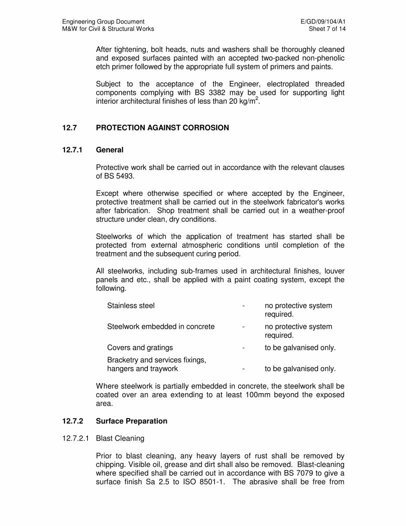
Engineering Group Document E/GD/09/104/A1 M&W for Civil & Structural Works Sheet 7 of 14
After tightening, bolt heads, nuts and washers shall be thoroughly cleaned and exposed surfaces painted with an accepted two-packed non-phenolic etch primer followed by the appropriate full system of primers and paints.
Subject to the acceptance of the Engineer, electroplated threaded components complying with BS 3382 may be used for supporting light interior architectural finishes of less than 20 kg/m
2.
12.7 PROTECTION AGAINST CORROSION
12.7.1 General Protective work shall be carried out in accordance with the relevant clauses
of BS 5493. Except where otherwise specified or where accepted by the Engineer,
protective treatment shall be carried out in the steelwork fabricator's works after fabrication. Shop treatment shall be carried out in a weather-proof structure under clean, dry conditions.
Steelworks of which the application of treatment has started shall be
protected from external atmospheric conditions until completion of the treatment and the subsequent curing period.
All steelworks, including sub-frames used in architectural finishes, louver
panels and etc., shall be applied with a paint coating system, except the following.
Stainless steel - no protective system
required.
Steelwork embedded in concrete - no protective system required.
Covers and gratings - to be galvanised only.
Bracketry and services fixings, hangers and traywork - to be galvanised only.
Where steelwork is partially embedded in concrete, the steelwork shall be coated over an area extending to at least 100mm beyond the exposed area.
12.7.2 Surface Preparation 12.7.2.1 Blast Cleaning
Prior to blast cleaning, any heavy layers of rust shall be removed by chipping. Visible oil, grease and dirt shall also be removed. Blast-cleaning where specified shall be carried out in accordance with BS 7079 to give a surface finish Sa 2.5 to ISO 8501-1. The abrasive shall be free from

Engineering Group Document E/GD/09/104/A1 M&W for Civil & Structural Works Sheet 8 of 14
contamination, and recovered material shall be cleaned to the acceptance of the Engineer before re-use. Non-metallic (containing Silica) abrasives shall not be used. The blast-cleaned surface shall have a surface profile height between 50 and 100 microns. Blast-cleaned steelwork shall be free from dust, mill scale and adherent particles. The first coat of primer shall be applied by an accepted airless spray process with the least possible delay and in any case, be within 2 hours of blast cleaning. The successive coats shall be applied within the time periods specified by the manufacturer. Suitable masks shall be provided at friction grip bolted connections to ensure that the friction surfaces are kept free of primer and paint.
12.7.2.2 Solvent Cleaning
The steelwork shall be solvent cleaned to remove all contamination and then washed with clean fresh water. Trapped water in crevices shall be blown out with clean dry compressed air. Solvent cleaning shall be repeated where necessary to the acceptance of the Engineer.
12.7.2.3 Hand & Mechanical Cleaning
Any heavy layers of rust shall be removed by chipping. Visible oil, grease and dirt shall also be removed. Hand and power tool cleaning shall be carried out to ISO 8501-1, St 3 grade to the acceptance of the Engineer. After hand and power tool cleaning, the steelwork surface shall be cleaned of loose dust and debris. All dust shall be removed by vacuum cleaning.
12.7.3 Galvanising
Galvanising for articles and products after fabrication shall be in accordance with BS EN 1461. The steelwork shall be pickled in dilute acid, then stove and dipped in a bath of spelter. Each article shall be covered evenly on all sides with zinc to achieve the specified thickness in Table 2 of BS EN 1461.
Unless otherwise accepted by the Engineer, cold formed or cold worked steel sections shall not be hot dip galvanised. Subject to the acceptance of the Engineer, light steel section used in the interior of buildings for supporting light architectural finishes may be fabricated from steel sheets or plates. The steel sheets or plates shall be hot dip galvanised in accordance to BS EN 10143. Except when otherwise permitted by the Engineer, the designation of the steel shall be BS EN 10143 sheet Z25G - 275 or of higher quality in terms of strength and corrosion protection.

Engineering Group Document E/GD/09/104/A1 M&W for Civil & Structural Works Sheet 9 of 14
12.7.4 Paints 12.7.4.1 General All paints shall comply with SS 5, SS 6, SS 7, SS 34, BS 7956 where
applicable unless otherwise stated. In addition, paints for steelwork shall comply with the following requirements:
(a) All paints forming part of any one painting system shall be obtained
from the same manufacturer. Paint shall be supplied in sealed containers of not more than 20 litres, unless otherwise accepted by the Engineer. Each container shall be clearly marked with the manufacturer's name, paint type, colour, production batch number, date of manufacture and pot life.
(b) Prior to the commencement of painting of steelwork, the Contractor
shall submit for the Engineer’s acceptance a full specification of the paint or paints he proposes to order, together with the name of the manufacturer whose paint he proposes to use. If instructed to do so by the Engineer, he shall supply liquid samples of the various paints concerned for examination and testing. No paint shall be used without the prior acceptance of the Engineer.
Paint that exceeds the “shelf life” specified on the container by the manufacturer, or paint that in the opinion of the Engineer has deteriorated and is not fit for use, shall be rejected. Primers and paints shall be applied strictly in accordance with the manufacturer’s recommendations and shall be carried out by skilled painters under a competent supervisor. The Contractor shall submit the particulars of the supervisor for the Engineer’s acceptance.
12.7.4.2 Application
Paint shall not be applied when the relative humidity is in excess of 85 per cent, or when the surface temperature is less than 3
oC above the dew point
temperature, or when the temperature of the surface to which the coating is applied, is greater than 55°C.
Paints shall be used strictly in order of delivery from the manufacturer. Paint shall not be used after the expiration of the pot-life stipulated by the manufacturer, and paints of limited pot-life shall not be mixed with fresh paint or have thinners added to them. Painting processes and methods shall be to the acceptance of the Engineer. All tools, solvents and plant used shall be such as to obtain the best possible results and shall be maintained in good condition throughout. Each coat of paint shall be applied by the methods specified, or by other methods accepted by the Engineer, so as to produce a continuous film of paint of uniform and even thickness. Successive coats shall be of a

Engineering Group Document E/GD/09/104/A1 M&W for Civil & Structural Works Sheet 10 of 14
different shade so that the coverage of each coat is clearly visible. Each coat shall be thoroughly dry and cleaned of all dust and loose paint before the application of a further coat. Where required by the Engineer, surfaces shall be cleaned by washing down with a solution of accepted liquid detergent, followed by rinsing with clean, fresh water.
Following the application of the final shop coat on any member, a curing period of not less than 36 hours shall be allowed before exposure to external atmospheric conditions. Wherever practicable, successive coats in paint systems should differ in colour. However, manufacturer's recommendations in respect of the colours of the undercoats and first coat should be observed.
12.7.4.3 Type of Coating Systems
Systems 1, 2, 3 and 4 are for the following applications: - System 1 – Steelwork not visible to the public. - System 2 – Steelwork visible to the public (Alternative 1). - System 3 – Steelwork visible to the public (Alternative 2). - Systems 2A and 3A are normal repair procedures to Systems 2 and 3 respectively.
- System 3B is a less demanding repair procedure to System 3A suitable
for rafters, purlins and the like.
- System 4 – Steelwork exposed to highly aggressive environmental conditions.
Details of the coating system shall be in accordance to Table 12.1.
12.7.4.4 Coating Specifications The properties of the coatings shall be as follows:
A. Two-Pack Epoxy Zinc Rich Primer - two component epoxy polyamide cured - high flash point - fast drying - at least 85% zinc content in the dry film - at least 60% volume solids B. Two-Pack Epoxy Micaceous Iron Oxide High Build Primer - two component epoxy polyamide cured - high build product - indefinite period for overcoating

Engineering Group Document E/GD/09/104/A1 M&W for Civil & Structural Works Sheet 11 of 14
- designed to be used as sealer coat over zinc epoxy primer - micaceous iron oxide pigmentation - at least 65% volume solids C. Two-Pack Epoxy Fade Resistant Chemical Resistant Pigmented Paint - High Build Paint - two component epoxy polyamide cured high build product - resistant to fumes and spillage of mild acids, alkalis, salts and solvents - chemical and weather resistant pigmentation - at least 60% volume solids
D. Two-Pack Polyurethane Fade-Resistant Chemical Resistant Pigmented Finish Paint - two component polyurethane isocyanate cured - very high gloss finish - high abrasion resistance - excellent chemical and solvent resistance - chemical and weather resistant pigmentation - at least 60% volume solids E. Surface Tolerant Epoxy Primer - two component epoxy aromatic amine cured - designed for use over surface finish St 3 grade to ISO 8501-1. - high film thickness achievable by brush application - aluminum paste pigmentation good chemical and solvent resistant - long overcoating time-up to 6 months with polyurethane - at least 80% volume solids
F. Inorganic Zinc Silicate Primer - two component zinc silicate ethyl primer - at least 85% zinc content in dry film - temperature resistant up to 400
0C
- at least 60% volume solids G. Epoxy Primer– For Galvanised/Stainless/Carbon Steel Surfaces - two component epoxy polyamide cured - at least 57% solids ratio by volume.
H. Two-pack Tar Free Epoxy - two component high solids polyamine adduct cured tar free epoxy. - at least 80% solids ratio by volume. - mixing ratio of base and hardener by volume 75:25.
12.7.4.5 Coating Continuity and Thickness The Contractor shall institute a quality control system that is acceptable to
the Engineer to check the continuity and thickness of paint or metal coatings with the aid of approved electronic measuring devices which are capable of measuring the resistance of the coatings. Measurements shall comply with the recommendations of SS 5.

Engineering Group Document E/GD/09/104/A1 M&W for Civil & Structural Works Sheet 12 of 14
12.7.4.6 Compatibility The Contractor must ensure that all paints within a system have
compatibility between coats and with the metal substrate. There should be adequate adhesion to substrate and between coats over the operating temperature range and there should be no under-softening to cause lifting, wrinkling or bleeding through of stains. Unless otherwise permitted by the Engineer, all components of a paint system shall be from the same manufacturer.
12.7.4.7 Toxicity All paints and coatings must be non-toxic and shall not create a toxic hazard
during application. All paints and coatings shall not produce toxic fumes or other toxic materials when exposed to fire, so as not to cause risk to human health.
The Contractor shall submit test certificates from approved testing
laboratories, which are acceptable to the Engineer attesting to the non-toxicity of the paints and coating.
12.7.4.8 Degreasing Degreasing shall be carried out using a water-based degreaser. The
emulsified residue shall be washed off with a copious amount of fresh water. Trapped water in crevices shall be blown out with clean dry compressed air. Degreasing and washing shall be repeated where necessary to the acceptance of the Engineer.
12.7.5 Handling Lifting and handling methods used during the protective treatment and in
subsequent transport, storage and erection shall be such as to ensure that damage to the treatment is kept to the absolute minimum. Such damage as does occur shall be made good by cleaning to bare metal and re-applying the full painting system. The new paint shall overlap the existing paint by at least 50 mm all round the affected part.
12.7.6 Delivery and Storage All delivery of steelworks shall be accompanied with an Inspection Release
Notes (IRN) certified by the Engineer’s site representative. Steelworks delivered to site which, in the opinion of the Engineer, is not in accordance with this Specification for cleaning and shop painting, shall be returned to the steelwork fabricator's workshop. The existing painting system shall be completely removed and the full system re-applied to the acceptance of the Engineer.

Engineering Group Document E/GD/09/104/A1 M&W for Civil & Structural Works Sheet 13 of 14
Where it is necessary to store painted fabricated steelwork prior to erection,
it shall be kept clear of the ground and stacked in such a manner as to ensure that no pools of water or dust accumulate on the surfaces. Suitable packing shall be provided between layers of stacked steelwork. Covers, when provided, shall be well ventilated.
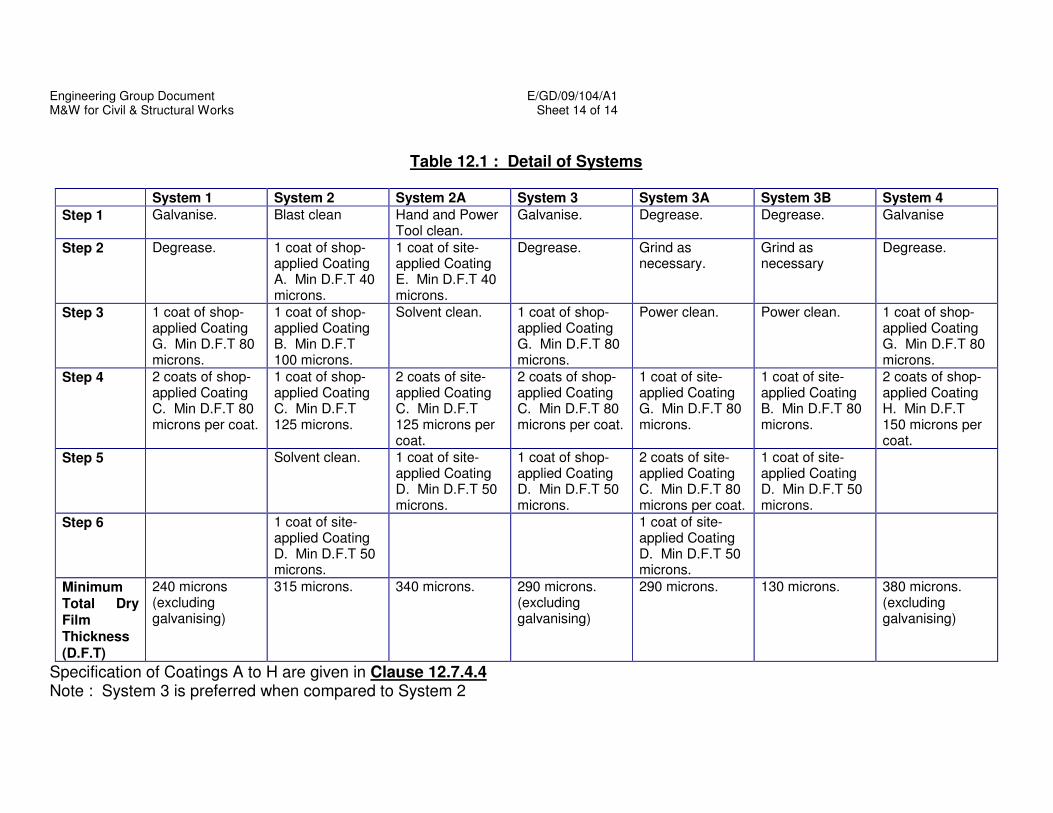
Engineering Group Document E/GD/09/104/A1 M&W for Civil & Structural Works Sheet 14 of 14
Table 12.1 : Detail of Systems
System 1 System 2 System 2A System 3 System 3A System 3B System 4
Step 1 Galvanise. Blast clean Hand and Power Tool clean.
Galvanise. Degrease. Degrease. Galvanise
Step 2 Degrease. 1 coat of shop-applied Coating A. Min D.F.T 40 microns.
1 coat of site-applied Coating E. Min D.F.T 40 microns.
Degrease. Grind as necessary.
Grind as necessary
Degrease.
Step 3 1 coat of shop-applied Coating G. Min D.F.T 80 microns.
1 coat of shop-applied Coating B. Min D.F.T 100 microns.
Solvent clean. 1 coat of shop-applied Coating G. Min D.F.T 80 microns.
Power clean. Power clean. 1 coat of shop-applied Coating G. Min D.F.T 80 microns.
Step 4 2 coats of shop-applied Coating C. Min D.F.T 80 microns per coat.
1 coat of shop-applied Coating C. Min D.F.T 125 microns.
2 coats of site-applied Coating C. Min D.F.T 125 microns per coat.
2 coats of shop-applied Coating C. Min D.F.T 80 microns per coat.
1 coat of site-applied Coating G. Min D.F.T 80 microns.
1 coat of site-applied Coating B. Min D.F.T 80 microns.
2 coats of shop-applied Coating H. Min D.F.T 150 microns per coat.
Step 5 Solvent clean. 1 coat of site-applied Coating D. Min D.F.T 50 microns.
1 coat of shop-applied Coating D. Min D.F.T 50 microns.
2 coats of site-applied Coating C. Min D.F.T 80 microns per coat.
1 coat of site-applied Coating D. Min D.F.T 50 microns.
Step 6 1 coat of site-applied Coating D. Min D.F.T 50 microns.
1 coat of site-applied Coating D. Min D.F.T 50 microns.
Minimum Total Dry
Film Thickness
(D.F.T)
240 microns (excluding galvanising)
315 microns. 340 microns. 290 microns. (excluding galvanising)
290 microns. 130 microns. 380 microns. (excluding galvanising)
Specification of Coatings A to H are given in Clause 12.7.4.4 Note : System 3 is preferred when compared to System 2
Engineering Group Document E/GD/09/104/A1 M&W for Civil & Structural Works Sheet 1 of 9
CHAPTER 13
ABOVE-GROUND STRUCTURES
13.1 GENERAL
This Chapter addresses requirements for above-ground structures that include: (a) all above-ground stations and trainways, (b) vehicular bridges, (c) cycle and pedestrian bridges, (d) bus shelters and (e) covered linkways.
13.2 TRIAL SECTIONS 13.2.1 Columns The Contractor shall construct a trial typical column with crossheads/
column heads to the Engineer’s acceptance. The trial sample shall satisfy the following requirements:
(a) All features, e.g. feature grooves, recesses and test boxes, etc. shall
be incorporated. (b) It shall be constructed in parts with construction joints similar to that intended for the Permanent Works. If the trial column is rejected, further trial columns shall be erected until a satisfactory standard is achieved. The approved trial column shall be the standard of acceptability for the columns.
13.2.2 Girders The Contractor shall construct a trial typical column with crossheads/
column heads to the Engineer’s acceptance. The trial sample shall satisfy the following requirements:
(a) It shall be at least 1.5m long.
(b) All features, e.g. feature grooves, parapets, etc. shall be incorporated.
(c) It shall be constructed in parts with construction joints similar to that intended for the Permanent Works.

Engineering Group Document E/GD/09/104/A1 M&W for Civil & Structural Works Sheet 2 of 9
If the trial girder is rejected, further trials shall be erected until a satisfactory standard is achieved. The approved trial girder shall be the standard of acceptability for the Permanent Works.
13.3 WATERPROOFING SYSTEMS 13.3.1 RTS Structures with Stray Currents 13.3.1.1 Materials The waterproofing and insulation membrane shall be fully bonded to the
entire length of the viaduct deck. The membrane shall, at all times during construction be fully protected from any damage.
The Contractor shall submit for acceptance the proposed bonded
waterproofing membrane system and the applicator approved by the manufacturer. The bonded waterproofing membrane shall satisfy the following requirements and other relevant requirements contained in the Specifications.
(a) Electrical resistivity not less than 5000 x 10
11 ohm-cm (ASTM D257-
89) (b) Tensile strength of the membrane not less than 5000 kPa (ASTM
D412) (c) Elongation at maximum load not less than 400% (ASTM D412) (d) Puncture resistance not less than 95 kgf in accordance with ASTM
E154 (e) Adhesion of membrane to concrete not less than 900 kPa (ASTM
D1851 withdrawn) (f) Minimum lapping at any joint shall be not less than 100mm
(g) Total thickness of the membrane not less than 2.50mm (ASTM
D751) (h) Reinforcement of the membrane shall be non-woven polyester not
less than 180 gm/m2.
The Contractor shall submit the test reports as stated above. The Engineer may require tests to be carried out on the samples of the membrane to verify the properties. Waterproofing and insulation membrane laid on horizontal surfaces shall be protected by reinforced concrete screed. On non-horizontal surfaces, it shall be laid to fall for drainage purposes.

Engineering Group Document E/GD/09/104/A1 M&W for Civil & Structural Works Sheet 3 of 9
13.3.1.2 Shop Drawings and Method Statement The Contractor shall submit comprehensive shop drawings and method
statement showing all details and procedures for the waterproofing works including those at the movement joints, drainage and penetration points.
The Contractor shall submit a Method statement describing the details of
the waterproofing works including protective measures at all stages. It shall be prepared in conjunction with the applicator and duly endorsed by the manufacturer of the membrane. The Method statement shall be subject to the Engineer’s acceptance prior to any waterproofing work.
13.3.1.3 Application The membrane shall form a continuous layer over the viaduct deck to the
extent shown on the Drawings and shall be applied in accordance with the approved Method Statement.
The Contractor shall take precautions to ensure that: (a) Once installed, the waterproofing and insulation membrane shall be
protected from damage until the concrete screed is placed and cured. (b) Particular attention shall be given to the avoidance of damage to the
membrane when placing the reinforcement mesh and in-situ concrete screed.
(c) The time period between the installation of a section of membrane and
the placing of its protective screed or tiles shall not be more than 7 working days.
(d) Construction traffic shall not be allowed to pass over the completed
screed until it has attained a minimum cube strength of 20 MPa. 13.3.1.4 Warranty The performance of the viaduct decking waterproofing shall be warranted
for a minimum period of ten (10) years from the date of Completion of the Contract. All defects occurring during this warranty period are to be made good by the Contractor. The warranty shall be given jointly and severally by the Contractor and the supplier/applicator and shall be in the format given in the General Specification.
13.3.1.5 Water Ponding Test After the completion of the waterproofing membrane installation, at least 2%
of the total length or total number of spans, whichever is more onerous and subject to a minimum of 1 span of the viaduct deck shall be ponded to test for leakage and seepage.

Engineering Group Document E/GD/09/104/A1 M&W for Civil & Structural Works Sheet 4 of 9
The Contractor shall provide all temporary kerbs in cement mortar or by other means to provide enclosures to contain ponding water. All rainwater outlets must be plugged and the entire viaduct is flooded with 75 mm of clean water for three days, after which the viaduct shall be inspected for any sign of water penetration.
Should there be defective areas, the Contractor shall bear the entire cost of remedying the defects by an accepted method and re-testing to the acceptance of the Engineer. On satisfactory completion of the ponding test, the Contractor shall carefully break up and remove any kerb or temporary barrier and plugs to outlets and remove all debris. The Contractor shall take care in doing so to prevent damage to the viaduct structure or surface. Ponding water shall be drained by accepted means and steps must be taken at all times to prevent breeding of mosquitoes and choking of rainwater down pipes.
13.3.2 RTS Structures without Stray Currents The entire length of the viaduct decks without stray currents shall be
applied with approved waterproofing agent. The waterproofing agent shall be applied by the manufacturer’s approved applicators strictly in accordance with the approved Method Statement.
Joints between pre-cast segments shall be sealed with approved epoxy
resin mortars before the application of the waterproofing agent. The joint detail shall be submitted to the Engineer for acceptance.
The workmanship, submissions and testing requirement specified in
Clause 13.3.1.2, 13.3.1.4 and 13.3.1.5 shall apply. 13.3.3 Flower Troughs and Planting/ Turfing Areas on Bridge Decks The entire length of viaduct flower trough and entire planting/ turfing areas
on bridge decks shall be applied with a crystallisation-waterproofing agent. The waterproofing material, sample, specifications and application method
statement shall be submitted for the Engineer’s acceptance.
13.4 DECK DRAINAGE SYSTEM 13.4.1 General Unless otherwise specified, the Contractor shall design the connections of
the drainage pipe system. All drainage pipe system shall be:
(a) heavy-duty UPVC pipes in compliance with BS4660.
Engineering Group Document E/GD/09/104/A1 M&W for Civil & Structural Works Sheet 5 of 9
(b) tested by application of air pressure upon completion. Inlet units as
shown on the Drawings shall be cast in, and connected to the waterproofing in accordance with the manufacturer’s instruction.
Prior to casting, all cast-in pipework shall be rigidly supported, and shall be checked for alignment and tested for water tightness. All steel fixing shall be galvanised in accordance with the Specifications.
13.4.2 Road Deck Drainage The longitudinal drainage carrier pipes shall not be smaller than 100mm
diameter with rodding eyes at intervals not more than 20 m. The vertical drainage down pipes shall not be smaller than 200mm
diameter with rodding eyes provided at each end of the outlet pipes and where ever there are changes in direction.
Where asphalt drainage mix is used on the bridge deck and unless otherwise specified, the design for the drainage system shall be based on HA 79/97 Part 4 and the following criteria: - (a) The drainage system shall comprise 2-part lift-off units that can give
easy access to the channel for easy inspection, cleaning and maintenance. The drainage system shall have continuous drainage slots to ensure effective discharge of surface run-off and subsurface run-off where drainage asphalt surfacing is used.
(b) The drainage system units shall be designed for wheel loads
specified in the LTA Design Criteria.
(c) The top surface of the drain units shall be non-slip. (d) The capacity of the drainage system shall comply with PUB,
Drainage Department Code of Practice. The Contractor shall submit all relevant calculations endorsed by his Professional Engineer to the Engineer’s acceptance and PUB Drainage Department for approval.
The Contractor shall submit a comprehensive method statement for the installation and future replacement of the drain units to the Engineer’s acceptance.
13.4.3 RTS Deck Drainage For RTS viaduct structures, the UPVC down pipes shall be cast in the
column. Where there is waterproofing and insulation membranes on the deck, they are to be properly tucked into the collar inlet.
Engineering Group Document E/GD/09/104/A1 M&W for Civil & Structural Works Sheet 6 of 9
13.5 PARAPETS AND RAILINGS 13.5.1 General For road viaduct, the typical details as shown in the Standard Details of
Road Elements, shall be adopted. The bridge parapet profiles and designs shall comply with BS 6779 and BD 52/93.
The metal railings shall be made of aluminium alloy. Railings and parapet
system shall meet the static and dynamic testing requirements, as specified in BS 6779.
The Contractor shall submit the detailed design, drawings and the
dynamic test reports to the Engineer for acceptance before any order is placed.
13.5.2 Fabrication of Parapet/ Railings Parapets shall be fabricated in accordance with the Drawings. Bridge
parapet railings shall comply with the following standards: (a) Posts and rail end caps to BS 1490 (b) Rail tubes to BS 1474 (c) Plates to BS EN 515
(d) Stainless steel bolts to BS 970: Part 4 (e) Stainless steel holding-down bolts to BS EN ISO 3506-1: Grade A4-
80
13.5.3 Alignment of Parapets The finished parapets shall be true to line and level throughout their length.
The face of the rails shall present an even finish on the traffic face. Rails of curved panels having a horizontal curvature less than 300 metres shall be rolled to smooth curves.
Panels and members shall be free from twist and the posts shall be truly
vertical. 13.5.4 Welding Welding for aluminium and aluminium alloy parapets shall comply with the
requirements of either BS 3019-1 or BS 3571: Part 1.

Engineering Group Document E/GD/09/104/A1 M&W for Civil & Structural Works Sheet 7 of 9
13.5.5 Static Loading and Material Testing 1% of the parapet railings, posts and bolts supplied shall be chosen by the
Engineer for static and material testing in accordance with BS 6779 and BD 52/93 at an accredited laboratory. All costs involved shall be borne by the Contractor.
13.5.6 Aluminium Parapets and Fascias for RTS Viaducts The Contractor shall be responsible for the design and detailing of the
aluminium parapets and fascias where specified in the Drawings. Detailed drawings, calculations and method statement for installation shall be submitted for acceptance by the Engineer.
13.6 PRECAST DECK FURNITURE FOR RTS VIADUCTS Precast concrete units where installed shall be true to line and level
throughout their lengths, along the viaduct structures The Contractor shall design and detail the panels to suit installation on the beams.
The holding down bolts/sockets shall not be in contact with any of the
steel reinforcing bars in the viaduct structures. 13.7 LAUNCHING OF PRECAST ELEMENTS 13.7.1 General
The Contractor shall inform the Engineer at least one month in advance of each launching operation and submit the following to the Engineer for acceptance: (a) Method statement including launching systems and transportation, (b) Proposal for traffic diversion, as appropriate, (c) Detailed programme of each launching operation.
13.7.2 Transportation The Contractor shall obtain the necessary clearances for the
transportation of the pre-cast elements and movement of the lifting equipment to the launching site. Contractor’s method of transportation shall demonstrate that the elements being transported would not be damaged.
A certificate of test of lifting equipment shall be submitted to the Engineer,
together with particulars of the experiences of the operator.
Engineering Group Document E/GD/09/104/A1 M&W for Civil & Structural Works Sheet 8 of 9
13.7.3 Ground preparation The ground of the launching area shall be prepared to ensure that it is
safe to carry the load during launching operation. 13.7.4 Erection Utmost precautions shall be taken to eliminate any danger to the workers
and general public while launching pre-cast elements. All lifting equipment shall be designed, such that if the primary lifting mechanism fails, a secondary mechanism will ensure that the pre-cast element does not fall.
Upon erection, a fail-safe method shall be used to temporarily secure the pre-cast unit until the permanent fixing arrangements are implemented. The securing systems, subject to the Engineer’s acceptance shall include: (a) Providing chains between beams and supports; (b) Connecting adjacent beams by welding protruding bars of the beams;
or temporary bracings between the beams; (c) Providing wedges or brackets to the beams.
The Contractor shall:
a) Ensure that appropriate and sufficient warning signs, lights,
barricades and at least one rotating amber light are placed at each point of road closure or diversion in accordance with the LTA’s Code Of Practice For Temporary Traffic Control.
b) Station at least one person in a safe position at each point of road
closure, to advise and guide motorists. The person shall be equipped with a torch, reflective vest and walkie-talkie or other mean of communications within the launching site.
c) Have one person controlling the whole launching operation with a
whistle or other mean of communications with the lifting equipment operators.
d) Ensure that there is sufficient lighting at the launching site. e) Ensure that no welding work on the bridge is carried out unless a
protective screen is used to prevent sparks and other materials from falling onto the areas below.
f) Install 4.5m height restriction signs of standard design immediately
after launching of any pre-cast element above existing carriageway.

Engineering Group Document E/GD/09/104/A1 M&W for Civil & Structural Works Sheet 9 of 9
g) Measure and record the actual height clearance of the bridge at
every 2m along the span of the bridge above the carriageway. h) Measure and record the location of the smallest clear height between
the carriageway and the bridge. i) Submit measurements showing that the height clearance of the
bridge satisfies the minimum clearance to the Engineer before opening the road under the bridge to traffic.
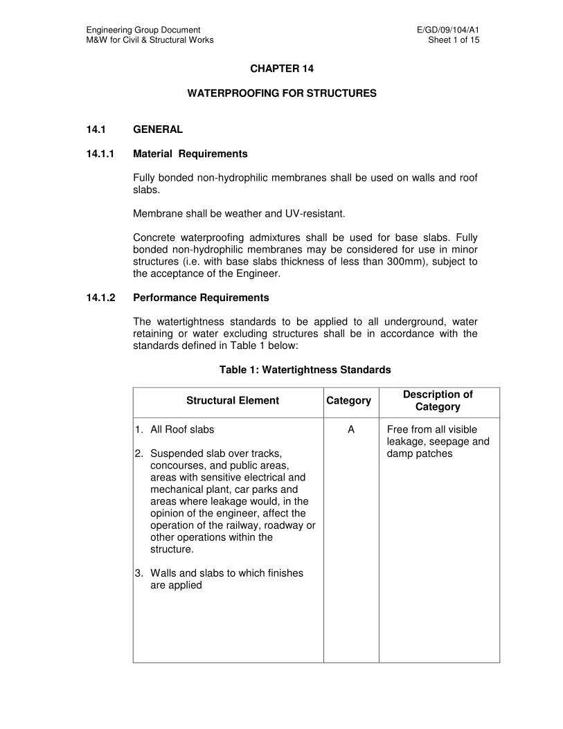
Engineering Group Document E/GD/09/104/A1 M&W for Civil & Structural Works Sheet 1 of 15
CHAPTER 14
WATERPROOFING FOR STRUCTURES
14.1 GENERAL
14.1.1 Material Requirements
Fully bonded non-hydrophilic membranes shall be used on walls and roof slabs.
Membrane shall be weather and UV-resistant. Concrete waterproofing admixtures shall be used for base slabs. Fully bonded non-hydrophilic membranes may be considered for use in minor structures (i.e. with base slabs thickness of less than 300mm), subject to the acceptance of the Engineer.
14.1.2 Performance Requirements
The watertightness standards to be applied to all underground, water retaining or water excluding structures shall be in accordance with the standards defined in Table 1 below:
Table 1: Watertightness Standards
Structural Element Category Description of
Category
1. All Roof slabs 2. Suspended slab over tracks,
concourses, and public areas, areas with sensitive electrical and mechanical plant, car parks and areas where leakage would, in the opinion of the engineer, affect the operation of the railway, roadway or other operations within the structure.
3. Walls and slabs to which finishes
are applied
A Free from all visible leakage, seepage and damp patches
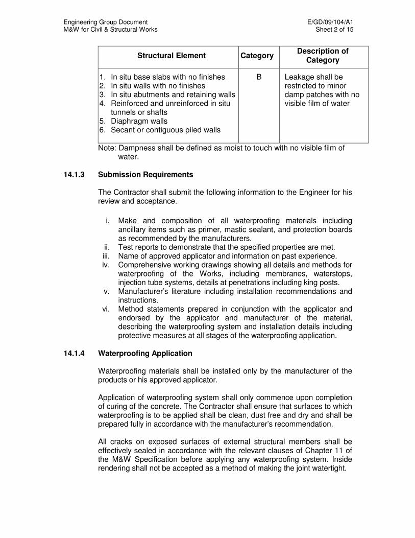
Engineering Group Document E/GD/09/104/A1 M&W for Civil & Structural Works Sheet 2 of 15
Structural Element Category Description of
Category
1. In situ base slabs with no finishes 2. In situ walls with no finishes 3. In situ abutments and retaining walls 4. Reinforced and unreinforced in situ
tunnels or shafts 5. Diaphragm walls 6. Secant or contiguous piled walls
B Leakage shall be restricted to minor damp patches with no visible film of water
Note: Dampness shall be defined as moist to touch with no visible film of water.
14.1.3 Submission Requirements
The Contractor shall submit the following information to the Engineer for his review and acceptance.
i. Make and composition of all waterproofing materials including
ancillary items such as primer, mastic sealant, and protection boards as recommended by the manufacturers.
ii. Test reports to demonstrate that the specified properties are met. iii. Name of approved applicator and information on past experience. iv. Comprehensive working drawings showing all details and methods for
waterproofing of the Works, including membranes, waterstops, injection tube systems, details at penetrations including king posts.
v. Manufacturer’s literature including installation recommendations and instructions.
vi. Method statements prepared in conjunction with the applicator and endorsed by the applicator and manufacturer of the material, describing the waterproofing system and installation details including protective measures at all stages of the waterproofing application.
14.1.4 Waterproofing Application
Waterproofing materials shall be installed only by the manufacturer of the products or his approved applicator.
Application of waterproofing system shall only commence upon completion of curing of the concrete. The Contractor shall ensure that surfaces to which waterproofing is to be applied shall be clean, dust free and dry and shall be prepared fully in accordance with the manufacturer’s recommendation. All cracks on exposed surfaces of external structural members shall be effectively sealed in accordance with the relevant clauses of Chapter 11 of the M&W Specification before applying any waterproofing system. Inside rendering shall not be accepted as a method of making the joint watertight.
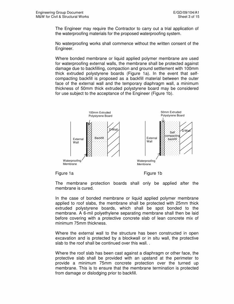
Engineering Group Document E/GD/09/104/A1 M&W for Civil & Structural Works Sheet 3 of 15
The Engineer may require the Contractor to carry out a trial application of the waterproofing materials for the proposed waterproofing system.
No waterproofing works shall commence without the written consent of the Engineer.
Where bonded membrane or liquid applied polymer membrane are used for waterproofing external walls, the membrane shall be protected against damage due to backfilling, compaction and ground settlement with 100mm thick extruded polystyrene boards (Figure 1a). In the event that self-compacting backfill is proposed as a backfill material between the outer face of the external wall and the temporary diaphragm wall, a minimum thickness of 50mm thick extruded polystyrene board may be considered for use subject to the acceptance of the Engineer (Figure 1b).
Figure 1a Figure 1b The membrane protection boards shall only be applied after the membrane is cured. In the case of bonded membrane or liquid applied polymer membrane applied to roof slabs, the membrane shall be protected with 25mm thick extruded polystyrene boards, which shall be spot bonded to the membrane. A 6-mil polyethylene separating membrane shall then be laid before covering with a protective concrete slab of lean concrete mix of minimum 75mm thickness. Where the external wall to the structure has been constructed in open excavation and is protected by a blockwall or in situ wall, the protective slab to the roof shall be continued over this wall. . Where the roof slab has been cast against a diaphragm or other face, the protective slab shall be provided with an upstand at the perimeter to provide a minimum 75mm concrete protection over the turned up membrane. This is to ensure that the membrane termination is protected from damage or dislodging prior to backfill.
Waterproofing Membrane
Backfill External
Wall
100mm Extruded Polystyrene Board
D/Wall
Waterproofing Membrane
D/Wall
Self compacting
backfill
External Wall
50mm Extruded Polystyrene Board

Engineering Group Document E/GD/09/104/A1 M&W for Civil & Structural Works Sheet 4 of 15
Damaged or non-compliant sections of membrane shall be repaired in accordance with the manufacturer's recommendations and as accepted by the Engineer. The primer shall be capable of conditioning the concrete to promote the adhesion of the membrane. In confined and poorly ventilated areas solvent-based primers shall not be used. The two layers of membrane shall be laid with a minimum lateral overlap of 55%; i.e. a minimum of two layers shall always be present with an additional layer locally at joints. Joint transverse to the direction of laying shall be avoided wherever possible by laying each roll of membrane in a continuous length as far as practicable. Unavoidable joints shall be provided with a minimum 150mm overlap with joints in adjacent sheets staggered by at least 500mm.
14.2 WATERPROOFING TO BASE SLABS OF UNDERGROUND
STRUCTURES 14.2.1 General Concrete waterproofing admixture shall be either of the hydrophobic and
pore-blocking or crystalline growth types. The admixture shall have a proven track record of successful application in similar conditions.
This admixture shall extend to the sidewalls of sumps and similar
depressions of the base slab so as to form a continuous watertight surface. The surfaces of such concrete shall be power floated whilst the concrete is still green in accordance with the manufacturer’s recommendations, and areas such as kickers shall be the subject to additional vibration and compaction. Plinths, for example for E&M plant, shall be cast with the base slab concrete.
Any admixtures or ingredient other than cement, aggregate or approved
water-reducing admixture, used by the Contractor to comply with the absorption and permeability requirements, must be shown by an independent authority to have had no reduction in performance after field exposure for a minimum of 15 years.
14.2.2 Concrete Waterproofing Admixture (Hydrophobic and Pore Blocking
Type) Where a concrete admixture, which is hydrophobic and pore blocking is
used it shall be applied to the top 300 mm (minimum) of base slabs. Prior to construction, trial mixes are to be conducted under the supervision
of the Engineer or his Representative and with the HPI manufacturer present to confirm that the proposed mix conforms to strength, w/c ratio,

Engineering Group Document E/GD/09/104/A1 M&W for Civil & Structural Works Sheet 5 of 15
slump and other requirements. The trial mix concrete shall further have a corrected 30-minute water absorption of not greater than 1.0%, (one percent) as measured by BS 1881: Part 122: 1983 except that the age at test shall be 7 days. The absorption test is to be conducted on cores taken from cubes or cylinders as specified in the standard. Cast specimens, 150mm x 75mm, may also be used for testing where approved by the Engineer, in which instance a correction factor will not be applied to the measured absorption result.
The trial mix concrete shall further have an average water permeability
coefficient when tested at 28 days of not greater than 5 x 10-13
m/s as measured by the HDB Test Method for Coefficient of Water Permeability (See Appendix 1) under 3.0 kgf/cm
2 (1989), or an average penetration
depth not greater than 15 mm as measured by DIN 1048: Part 5: 1991 test under 3.0 kgf/cm
2.
14.2.3 Concrete Waterproofing Admixture (Crystalline Growth Type) Alternatively, a concrete admixture that utilises a crystalline growth
mechanism may be used subject to the acceptance of the Engineer. The concrete admixture shall be applied to the full thickness of the base slab.
Prior to construction, trial mixes are to be conducted under the supervision
of the Engineer or his Representative and with the manufacturer present to confirm that the proposed mix conforms to strength, w/c ratio, slump and other requirements. The trial mix concrete shall further have an average water permeability coefficient when tested at 28 days of not greater than 5 x 10
-13 m/s as measured by the HDB Test Method for
Coefficient of Water Permeability under 3.0 kgf/cm2 (1989), and an
average penetration depth not greater than 15mm as measured by DIN 1048: Part 5: 1991 test under 3.0 kgf/cm
2.
14.3 WATERPROOFING TO WALLS OF UNDERGROUND STRUCTURES 14.3.1 External Walls To Structures Built in Open Excavation (Bonded
Membranes) Concrete surfaces to be waterproofed shall be prepared where necessary
by grinding and local filling with mortar having a steel trowelled finish to provide a smooth surface free from voids, loose aggregate and sharp protrusions. The surfaces shall be dry and free from oil, grease, curing compounds, loose particles, laitance, and all other contaminants.
The preformed membrane shall meet or surpass the following
requirements:-
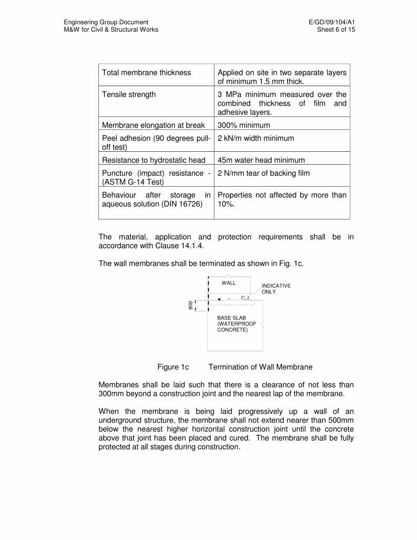
Engineering Group Document E/GD/09/104/A1 M&W for Civil & Structural Works Sheet 6 of 15
Total membrane thickness Applied on site in two separate layers of minimum 1.5 mm thick.
Tensile strength 3 MPa minimum measured over the combined thickness of film and adhesive layers.
Membrane elongation at break 300% minimum
Peel adhesion (90 degrees pull-off test)
2 kN/m width minimum
Resistance to hydrostatic head 45m water head minimum
Puncture (impact) resistance - (ASTM G-14 Test)
2 N/mm tear of backing film
Behaviour after storage in aqueous solution (DIN 16726)
Properties not affected by more than 10%.
The material, application and protection requirements shall be in accordance with Clause 14.1.4. The wall membranes shall be terminated as shown in Fig. 1c.
Figure 1c Termination of Wall Membrane
Membranes shall be laid such that there is a clearance of not less than 300mm beyond a construction joint and the nearest lap of the membrane. When the membrane is being laid progressively up a wall of an underground structure, the membrane shall not extend nearer than 500mm below the nearest higher horizontal construction joint until the concrete above that joint has been placed and cured. The membrane shall be fully protected at all stages during construction.
WALL INDICATIVE ONLY
C.J
BASE SLAB (WATERPROOF CONCRETE)
800
Engineering Group Document E/GD/09/104/A1 M&W for Civil & Structural Works Sheet 7 of 15
14.3.2 External Walls to Structures Built in Open Excavation (Spray Applied
Liquid Polymer Membrane) The spray applied liquid polymer membrane shall be suitable for use in an ambient temperature range not greater than 40
o C .It shall allow diffusion
of water vapour to prevent any build up of pressure between the membrane and substrate. The membrane shall meet or surpass the following requirements:-
Total membrane thickness 2.5mm minimum dry film thickness and sprayed in a minimum of two coats of contrasting colours, with the second coat applied to the first coat only after the first coat has cured.
Tensile strength 4.0 MPa minimum in any of the three orthogonal planes of the membrane
Membrane elongation at break 130% minimum
Peel adhesion to concrete (ASTM D4541)
2.0 MPa minimum
Static crack bridging (tested to recognised international standard acceptable to the Engineer)
2mm minimum
The cured membrane shall be chemically resistant to the effects of seawater, hydraulic fluids, diesel fuel and diluted mineral acids etc. The substrate shall be prepared and primed in strict accordance with the manufacturer's recommendations and requirements. The membrane shall be of a thixotropic nature and cold applied to ensure consistent thickness is achieved over all substrate irregularities. The materials used must be based upon resin systems that do not react with moisture although the substrate should be dry during application. The liquid polymer membrane shall be terminated in a chase or by a method acceptable to the Engineer. All components of waterproofing system shall be provided by one manufacturer. All materials must be supplied to site in unopened packaging, with batch numbers marked and corresponding manufacturer's certificates of conformity, and must be used within the product's shelf life. All components of the system exposed to rain within the curing period shall be replaced.

Engineering Group Document E/GD/09/104/A1 M&W for Civil & Structural Works Sheet 8 of 15
The membrane wet film thickness should be checked every 10 square metre during application of each layer, using a pin or comb gauge. Destructive testing to measure dry film thickness shall be carried out on the cured membrane at every 100 square metre or at every working shift, whichever occurs sooner, and shall be made good to the satisfaction of the Engineer. Holiday tests or similar tests to the acceptance of the Engineer shall be carried out on the cured membrane to identify any discontinuities in the membrane and to prove the integrity of the membrane.
14.3.3 Diaphragm Walls
All leaks in the diaphragm walls shall be sealed. At the junctions with the base slab and roof slab, two horizontal continuous runs of re-injectable grout tubes, appropriately spaced within the slab sections shall be installed on properly prepared surfaces to the satisfaction of the Engineer. After completion of the base slab but before concreting of the in situ wall, the junction with the base slab shall be grout injected. Typical details showing these requirements are illustrated in Figures 2(a) & 2(b).
Figure 2(a) Details at Diaphragm Wall/Roof Slab Interface
ROOF SLAB
TWO HORIZONTAL RUNS OF GROUT TUBES TO BE INSTALLED ON PROPERLY PREPARED DIAPHRAGM WALL SURFACES TO THE SATISFACTION OF THE ENGINEER
INDICATIVE ONLY
IN-SITU WALL
C.J.
WATERPROOFING MEMBRANE TO BE TUCKED INTO 25x25 mm CHASE AND SEALED WITH APPROVED SEALANT (CONCRETE SURFACES TO RECEIVE MEMBRANE SHALL BE PREPARED IN ACCORDANCE WITH MANUFACTURER’S REQUIREMENTS)
25mm THK EXTRUDED POLYSTYRENE BOARDS
POLYETHYLENE SEPARATING MEMBRANE
DIAPHRAGM WALL BROKEN OUT/CUT OFF TO A DEPTH OF 2m FROM FINSHED GROUND LEVEL, UNLESS SHOWN OTHERWISE ON THE AUTHORITY’S DRAWINGS
WATERBAR ALONG DIAPHRAGM WALL PANEL JOINT
EXTENT OF GROUT
75mm THK PROTECTIVE SLAB 300

Engineering Group Document E/GD/09/104/A1 M&W for Civil & Structural Works Sheet 9 of 15
Figure 2(b) Details at Diaphragm Wall/Base Slab
Interface
Grout injection at the junction with the roof slab shall be carried out after completion of the roof slab. These junctions shall be re-grouted if necessary.
14.3.4 External Walls Built against Pile Walls or Rock or Soil Faces The face against which the in situ wall is to be cast shall be built up by
mortar with steel trowelled finish to provide a smooth surface free from voids, loose aggregate and sharp protrusions. Where the thickness of mortar would be excessive, concrete shall be cast as primary filler.
Where bonded membranes are applied to in situ concrete walls cast
against pile walls, rock or soil faces, the material and application requirements for primer and the waterproofing membrane shall be in accordance with the appropriate requirements of Cl.14.1.4. In addition a third layer of membrane shall be provided.
For membrane that is bonded to the external face of the in situ structural wall, the preformed membrane shall meet or surpass the following requirements:-
INDICATIVE ONLY
IN-SITU WALL
DIAPHRAGM WALL
BASE SLAB (WATERPROOF CONCRETE)
C.J.
TWO HORIZONTAL RUNS OF GROUT TUBES TO BE INSTALLED ON PROPERLY PREPARED DIAPHRAGM WALL SURFACES TO THE SATISFACTION OF THE ENGINEER
WATERBAR ALONG DIAPHRAGM WALL PANEL JOINT
EXTENT OF GROUT

Engineering Group Document E/GD/09/104/A1 M&W for Civil & Structural Works Sheet 10 of 15
Membrane thickness 1.2 mm minimum
Tensile strength (ASTM D412) HDPE Film 25MPa
Membrane elongation at break 300% minimum
Peel adhesion to concrete 750N/m
Resistance to hydrostatic head 70m water head minimum (tested at a lap joint)
Puncture resistance (ASTM E154) 990 N
Behaviour after storage in aqueous solution (DIN 16726)
Properties not affected by more than 10%
The adhesive layer of the composite membrane shall be factory applied. The adhesive layer shall be protected with a layer of weather–resistant removable film and shall also have sufficient strength to resist all impacts and other forces to which it may be subject prior to placing of the structural concrete. Surfaces to receive the membrane shall be prepared in accordance with the membrane manufacturer’s instructions and requirements. Proper accessories such as anchor strips, pipe collars, outside and inside corners, steel laminated plates etc. shall be used for the correct and secure application of the waterproofing system. The membrane shall be continued upwards to 300mm above roof slab level. Suitable provision shall be made for continuity of the membrane with the watertightness provisions to the structure.
14.4 WATERPROOFING TO ROOFS OF UNDERGROUND STRUCTURES
14.4.1 Roof Slabs with Bonded Membranes or Spray Applied Liquid Polymer Membrane
Concrete surfaces to receive the membrane shall be prepared in accordance with the membrane manufacturer's instructions and requirements. Where the external wall to the structure has been constructed in open excavation, the bonded membrane protecting the roof slab shall be turned down and provided with a minimum 300mm lap onto the wall membrane. Where the external wall has been cast against a pile wall or other face sealed by a waterproofing membrane, the roof membrane shall be turned up to provide a 300mm lap onto the wall membrane as shown in Figure 3.

Engineering Group Document E/GD/09/104/A1 M&W for Civil & Structural Works Sheet 11 of 15
Figure 3 Wall cast against a pile wall or other face sealed by a waterproofing membrane
Where the external wall is cast against a diaphragm wall and no wall membrane is provided, the roof membrane shall be turned up at least 300mm and into a 25mm x 25mm chase cut into the diaphragm wall and sealed with an approved sealant as shown in Fig. 2(a). After completion of each section of membrane, and before placing of the extruded polystyrene board and before casting the permanent protective slab, the system shall be tested by ponding with minimum 150mm of water for a 48-hour period. The water level shall be topped up as necessary over the 48-hour period. At the end of this period, the underside of the slab shall be inspected for water leakage or dampness. Where there is any evidence of water penetration, the membrane shall be removed locally and the surface of the concrete inspected. Any visible cracking or other defects that may permit water penetration, shall be sealed by grouting, following which new membrane shall be laid and the waterproofing again tested by ponding.
14.5 WATERPROOFING TO SURFACE AND PARTIALLY UNDERGROUND
STRUCTURES 14.5.1 Ground Slabs
Waterproofing to ground slabs shall be similar to that specified for base
slabs of underground structures. 14.5.2 External Walls Protruding Above Ground Level
Where external walls protrude above the ground level, the waterproofing membrane shall be terminated at least 150mm above the ground level. Continuity of waterproofing between the junction with above ground structure and the external walls must also be assured.
INDICATIVE ONLY WALL
ROOF
C.J.
75mm THK PROTECTIVE SLAB
WATERPROOFING MEMBRANE (CONCRETE SURFACES TO RECEIVE MEMBRANE SHALL BE PREPARED IN ACCORDANCE WITH MANUFACTURER’S REQUIREMENTS)
300
75
1 1.
25mm THK EXTRUDED POLYSTYRENE
POLYETHYLENE SEPARATING MEMBRANE
Engineering Group Document E/GD/09/104/A1 M&W for Civil & Structural Works Sheet 12 of 15
14.5.3 Roof and Other Exposed Slabs Waterproofing to roofs and other exposed slabs shall consist of a fully
bonded membrane system in accordance with the requirements for roofs of underground structures. The primer and membrane shall be applied in accordance with Clause 14.1.4.
Protection to the membrane shall be provided by a dimpled or otherwise
profiled polyethylene sheet, which permits drainage, 25mm thick extruded polystyrene boards, a 6-mil polyethylene separating membrane and concrete slab of minimum 75mm thickness.
At the perimeter of the roof, the termination of the waterproofing
membrane, drainage layer and protective slab shall be integrated with the architectural treatment to ensure proper drainage of water.
14.6 STRUCTURAL CONCRETE WORKS 14.6.1 General Notwithstanding the provision of the waterproofing system, the Contractor
shall construct his concrete works so as to minimize the likelihood of water penetration. Special attention shall be given in the compaction and curing of concrete in areas such as at construction joints, around dumbbell waterstops, king posts and other structural penetrations.
14.6.2 Construction Joints Construction joints shall be watertight. All construction joints in external
slabs and walls shall be provided with an effectively continuous waterstop and re-injectable grout tube.
Before placing new concrete against concrete that has already hardened,
the face of the cast concrete shall be treated in accordance with the relevant clauses of Chapter 11 of the M&W Specification.
14.6.2.1 Waterstops Waterstops shall be appropriate for the type of joint where they are used.
They shall have a proven satisfactory performance when used in similar conditions.
Waterstops shall be of either barrier type flexible PVC/rubber or
hydrophilic waterstops. All waterstops shall possess a hydrostatic resistance appropriate to the structure and joint in which they are installed.

Engineering Group Document E/GD/09/104/A1 M&W for Civil & Structural Works Sheet 13 of 15
Hydrophilic waterstops shall have a delayed swell action to prevent
premature expansion prior to concreting and shall have a volumetric increase of not less than 120%. The hydrophilic waterstop shall exhibit good consistency in swell rate during repeated wetting and drying cycle. The water-swellable component of the hydrophilic waterstop shall not leach from the carrier matrix under any conditions.
Hydrophilic waterstops shall be installed just before concreting and shall
be placed as near as possible to the face subject to hydrostatic pressure whilst conforming to the manufacturer’s requirement of minimum edge distance. They shall be firmly fixed in place so that they cannot be displaced during concreting.
14.6.2.2 Injection Tube System Injection tube system shall include tough, flexible and chemically inert
tubes, connecting tubes, junction boxes, grout, pumps and all other items required for their installation and use. The Contractor shall provide full details of his proposed injection tube system for the Engineer's review and acceptance.
The injection tube system shall be suitable for resinous or cementitious
grout and be capable of re-injection to seal joints. The injection tube shall be robustly fixed in place in accordance with the
manufacturer's instructions and recommendations. Junction boxes shall be installed in locations which are readily accessible
and which do not interfere with the use to which the structure will be put. Unless otherwise accepted by the Engineer, they shall be set into the concrete.
The Engineer may require the contractor to carry out trial application for
the proposed injection tube system. The injection hose shall be tested by injecting water through them.

Engineering Group Document E/GD/09/104/A1 M&W for Civil & Structural Works Sheet 14 of 15
14.6.3 Waterproofing Treatments to Pipes, King Posts and Other Penetrations
Typical details showing the minimum requirements for waterproofing
treatment around pipes and king posts are illustrated in Figures 4 and 5.
Figure 4 Treatment at Pipe Penetration
Figure 5 Treatment at King Post (Roof Slab)
14.7 WARRANTY The warranty shall cover the whole of the waterproofing systems and shall
be given jointly and severally by the Contractor and the Supplier/Applicator. They shall be in the format given in the General Specification.
WAL
HYDROPHILIC STRIP AROUND PIPE TO BE AS NEAR AS POSSIBLE TO SOIL FACE WHILST CONFORMING TO MANUFACTURER’S REQUIREMENTS
2 LAYERS OF 50mm THK EXTRUDED POLYSTYRENE BOARDS
WATERPROOFING MEMBRANE CUT AWAY AT THE JUNCTION OF PROTRUSION
2LIQUID APPLIED MEMBRANE ALL ROUND
PIPE 7
75mm THK PROTECTIVE SLAB
25mm THK EXTRUDED POLYSTYRENE BOARDS
KING POST
ROOF SLAB
150
AP
PR
OX
WATERPROOFING MEMBRANE
RECESS TO BE REINSTATED WITH NON-SHRINK GROUT
HYDROPHILIC STRIP AROUND KING POST TO BE AS NEAR TO SOIL FACE AS POSSIBLE WHILST CONFORMING TO MANUFACTURER’S REQUIREMENTS
HYDROPHILIC STRIP
POLYETHYLENE SEPARATING MEMBRANE

Engineering Group Document E/GD/09/104/A1 M&W for Civil & Structural Works Sheet 15 of 15
APPENDIX 1
Determination of Water Permeability in accordance with
HDB Pressure Cell Method 1. Specimens of 28 days cores of 100mm diameter by 50mm thick. 2. Specimens are placed between 2 metal plates and conditioned for 24 hours. 3. The test cell was filled up till overflowing to expel air. 4. The graduated tube was filled with water up to a height of about 2 metres. 5. The free end of the tube was connected to a test pressure of 3.0 kgf/cm
2.
6. The pressure was maintained throughout the test and the drop in water level in the
manometer was noted and recorded. 7. A constant rate of flow was achieved, i.e. when the difference between the highest
and lowest readings of the 4 consecutive readings taken at every 24 hours did not exceed 3mm.
8. The coefficient of permeability is then calculated.

Engineering Group Document E/GD/09/104/A1 M&W for Civil & Structural Works Sheet 1 of 16
CHAPTER 15
BEARINGS AND MOVEMENT JOINTS 15.1 GENERAL This Chapter provides the technical requirements for the design,
manufacture, testing, delivery and installation of:
(a) Mechanical pot bearings, (b) Laminated elastomeric bearings and (c) Movement joints.
15.2 BEARINGS 15.2.1 General All bearings shall be designed, manufactured and installed in accordance
with the requirements of BS 5400: Part 9.1 and Part 9.2, BD20/92 and BS 6177 as appropriate.
All bearings used in the Contract shall be from one supplier only, unless
otherwise accepted by the Engineer. 15.2.2 Warranty All bearings shall be warranted against all defects and any malfunctioning
for a minimum period of ten (10) years from the date of Completion of the whole of the Works and all defects occurring during this period shall be made good by the Contractor. The Warranty is to be provided jointly and severally by the Contractor and the manufacturer, and shall be in the format shown in the General Specification.
15.2.3 Bearing Design The specialist/ manufacturer shall carry out the detailed design of the
bearings. The bearings shall be designed for the loads and movements specified in the Drawings. The design shall meet the technical and testing requirements of this Specification and the Drawings.
For all construction methods, the bearings and their support structure shall
be detailed to prevent damage of the concrete cover. Provisions shall be made in the design for the removal and replacement of
the bearings, including all their fixings. All bearings shall be designed with suitable handling attachments to the bearings to facilitate the removal and replacement process.
Engineering Group Document E/GD/09/104/A1 M&W for Civil & Structural Works Sheet 2 of 16
15.2.4 Submissions The Contractor shall submit the following information for the Engineer’s
acceptance prior to placing an order for the bearings:
(a) The name of the proposed manufacturer(s) and the location where the bearing will be manufactured.
(b) Dimensions and general details of the proposed bearings. (c) Bearing fixing arrangements. (d) Protective treatments, where applicable. (e) Evidence of satisfactory performance, under similar conditions of a similar bearing type, which the manufacturer has produced. (f) Delivery programme (to site). (g) Method Statement for bearing replacement
All bearings shall be of a proven design. Untried materials and designs will
not be accepted. The Contractor shall submit detailed drawings, calculations, material
specification and method statement of bearing installation for the Engineer’s acceptance. The bearings shall not be manufactured until all relevant submissions have been accepted.
A Schedule of bearings that contains at least the following information shall
be submitted for the Engineer’s acceptance.
(a) Bearing layout with identifications marks, (b) Type of bearings (e.g. fixed, guided or free), (c) Bearing dimensions including height, (d) Design load effects (SLS and ULS), (e) Reversible and irreversible translation in mm (SLS and ULS) (f) Reversible and irreversible rotation in radians (SLS and ULS).
Movement directions shall be clearly indicated on the drawing.
15.2.5 Inspection of Bearings
Bearings shall be dismantled to enable visual inspection at the
manufacturer's works prior to delivery. 15.2.6 Marking, Delivery and Storage of Bearings All bearings shall be suitably marked to identify their types and locations.

Engineering Group Document E/GD/09/104/A1 M&W for Civil & Structural Works Sheet 3 of 16
15.2.6.1 Marking Permanent luminous ‘movement indicator’ shall be marked on the side of
the bearing plate. The markings shall be visible after installation to facilitate monitoring of the bearings. For in-situ post-tensioning, pre-setting shall be taken into consideration.
15.2.6.2 Delivery Bearings shall be delivered fully assembled. The upper and lower parts of
the bearing shall be secured with transportation bolts. 15.2.6.3 Storage Bearings shall be transported and unloaded carefully and then stored
under cover in clean and dry conditions until required. An inspection shall be carried out shortly before installation, and bearings that have been damaged in store shall be rejected.
15.2.7 Bearing Installation and Protection 15.2.7.1 General Bearings shall be installed strictly under the supervision of the specialist
supplier in accordance with the approved Method Statement and the Drawings.
Bearing seating shall be of mortar bedding of non- shrink cementitious
grout, polyester resin or epoxy resin, with cube crushing strength of at least 40 N/mm
2 (MPa) at 7 days. The seating shall not exceed 25mm in
height. Unless otherwise indicated in the Drawings, bursting and spalling reinforcement shall be designed and provided based on the applied load.
Transfer of superstructure weight on to bearings shall not be allowed until the bedding has developed sufficient strength.
15.2.7.2 Mechanical Pot Bearings
Prior to the installation of pot bearings, the position of box-outs provided, dimensions and levels of the substructures and all relevant information shall be investigated, verified and approved by Engineer.
15.2.8 Bearing Installation Tolerances The bearing plate shall not be recessed in to RC structure or the bedding.
Mechanical pot bearings and laminated elastomeric bearings shall be fixed
within the tolerances as shown in Table 15.1: -

Engineering Group Document E/GD/09/104/A1 M&W for Civil & Structural Works Sheet 4 of 16
Table 15.1 - Tolerance
Description Tolerances
(a) Variation from true level Simply-supported structures :
± 3 mm Continuous structures: 0.0001 times the sum of the adjacent
spans but not exceeding ± 5mm
(b) Tilt of top and base plates 1 in 500
(c) Centrelines of the bearing to their correct position
± 3mm
(d) Orientation on plan 1 in1000 (to required direction)
15.2.9 As-built Submission After the bearings have been installed, the Contractor shall take all
protection measures necessary to ensure that the bearings remain free from damage.
Upon completion, the Contractor shall submit as-built drawings for all the
bearings installed. The as-built drawings shall include information on the Schedule of bearings. The final recorded movements shall be based upon completion of the structure (not project).
15.2.10 Technical Requirements for Mechanical Pot Bearings 15.2.10.1 General The sliding plates shall be of stainless steel. Where bearings are provided with side guides, they shall be aligned in the
direction of movement as required in the design. PTFE filled with 25% glass fibres by weight shall be used to for the vertical
sliding surfaces to each rocker plate in contact with the side guides. The vertical sliding surfaces of the side guides shall be of stainless steel.
15.2.10.2 Design and Manufacture Bearings shall be fixed to the structures with fixing bolts or by similar means.
Reliance on friction between the surfaces of the bearing and its bedding medium is not permitted.
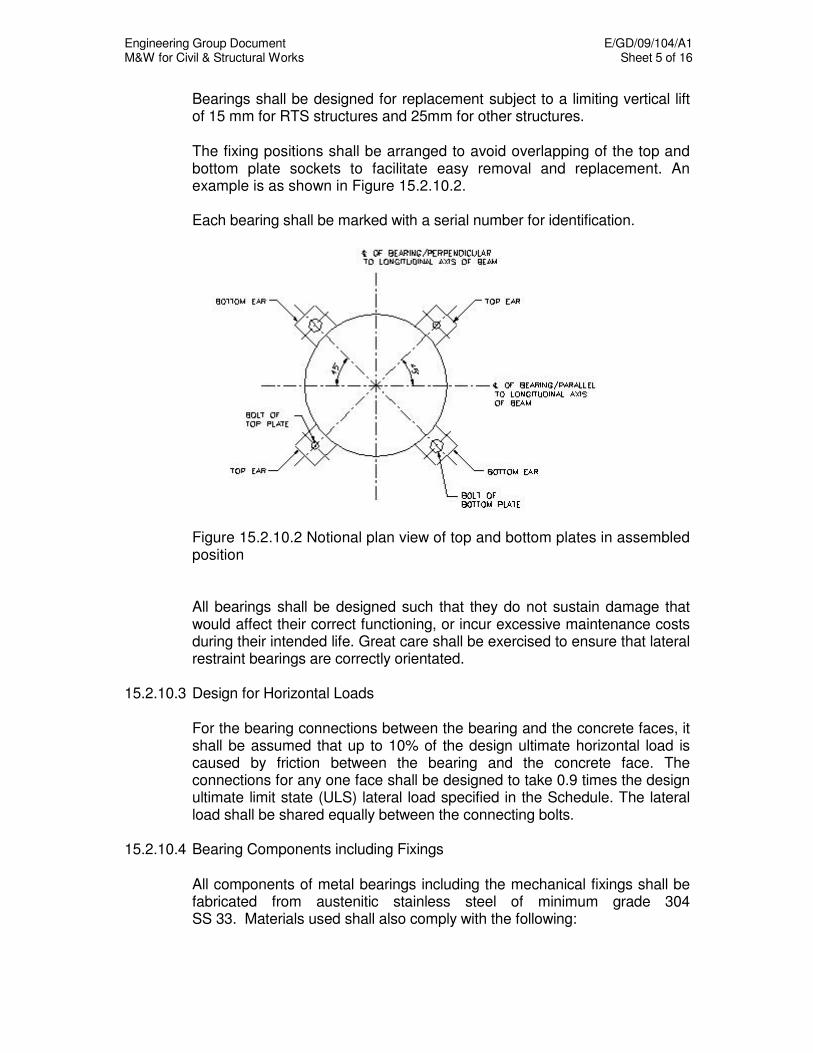
Engineering Group Document E/GD/09/104/A1 M&W for Civil & Structural Works Sheet 5 of 16
Bearings shall be designed for replacement subject to a limiting vertical lift of 15 mm for RTS structures and 25mm for other structures.
The fixing positions shall be arranged to avoid overlapping of the top and
bottom plate sockets to facilitate easy removal and replacement. An example is as shown in Figure 15.2.10.2.
Each bearing shall be marked with a serial number for identification.
Figure 15.2.10.2 Notional plan view of top and bottom plates in assembled position
All bearings shall be designed such that they do not sustain damage that
would affect their correct functioning, or incur excessive maintenance costs during their intended life. Great care shall be exercised to ensure that lateral restraint bearings are correctly orientated.
15.2.10.3 Design for Horizontal Loads For the bearing connections between the bearing and the concrete faces, it
shall be assumed that up to 10% of the design ultimate horizontal load is caused by friction between the bearing and the concrete face. The connections for any one face shall be designed to take 0.9 times the design ultimate limit state (ULS) lateral load specified in the Schedule. The lateral load shall be shared equally between the connecting bolts.
15.2.10.4 Bearing Components including Fixings All components of metal bearings including the mechanical fixings shall be
fabricated from austenitic stainless steel of minimum grade 304 SS 33. Materials used shall also comply with the following:
Engineering Group Document E/GD/09/104/A1 M&W for Civil & Structural Works Sheet 6 of 16
Wrought stainless steel : BS970 Part 1, grade 304
Flat rolled stainless steel : BS1449 Part 2, grade 304 Stainless steel Washers : BS 1449 Part 2, grade 304 Stainless steel fasteners : BSEN ISO 3506, grade A4-70 Stainless steel sliding surfaces of bearings shall receive no protective treatment and care shall be taken to protect these surfaces from being damaged or coated during the application of the protective treatment to other parts of the structure.
15.2.10.5 Additional Requirements for Bearing Replacement The total time for bearing replacement shall not exceed 4 hours for RTS
structures. The Contractor shall submit method statement on how the bearings can be
removed and replaced. The Contractor shall carry out bearing replacement trials by replacing bearings installed on the RTS structures to prove compliance with the criteria. The trials shall be carried out for each of the main bearing types selected at random by the Engineer.
The cost of carrying out the replacement trials shall be included in the
Contractor's contract price. Notwithstanding earlier acceptance, if the replacement requirements are not met, the Engineer shall reject all the bearings. Bearing used for the replacement test can be incorporated in the works provided it has not been damaged in any way during the replacement exercise.
The Contractor shall carry out bearing replacement trial after completion of
all viaduct deck finishes, handrail and parapet installation, permanent way, viaduct and cable. All designs shall be able to cope with the limiting vertical lift.
The warranty specified for the bearing shall not be invalidated due to the
replacement trial. 15.2.11 Testing Requirements for Mechanical Pot Bearings 15.2.11.1 General Tests shall be carried out at a laboratory accepted by the Engineer. The test
methods shall be subject Engineer’s acceptance. The equipment for testing the bearings shall be capable of determining to an accuracy of 3% of the design SLS load of the bearing to be tested and deflection to 0.1 mm.
All tests shall be carried out in the presence of the Engineer. The Engineer
shall be given at least 7 calendar days notice.

Engineering Group Document E/GD/09/104/A1 M&W for Civil & Structural Works Sheet 7 of 16
15.2.11.2 Routine Test Nominations for routine test for each bearing type shall be in accordance
with the following: - (a) 3 bearings out of the first batch of 10 bearings produced. (b) 1 bearing out of each subsequent batch of 10 bearings. However, if there are less than 6 bearings of one type, all bearings of that
type shall be load tested. Each bearing code number given in the Drawings shall be considered as a bearing type.
Routine tests for each bearing shall include:
- Vertical load test - Test for coefficient of friction (where applicable)
- Test for lateral load - Test for rotation
15.2.11.3 Additional Tests Should any bearing fail the routine tests, or the Contractor propose
modifications to the already accepted bearing details, additional bearing tests shall be performed to demonstrate compliance with the requirements. The type and number of additional tests shall be subject to the Engineer’s acceptance.
15.2.11.4 Test For Vertical Load The bearing shall be loaded in compression to 1.2 times the maximum
vertical SLS load given in the Drawings. The load shall be maintained for a minimum of three minutes.
15.2.11.5 Test For Coefficient Of Friction The coefficient of friction of the sliding surfaces of the bearing shall be
determined by test. The value of the coefficient of friction shall be taken as the average result of five tests and shall be determined for both the maximum and 50% of the maximum vertical SLS load given in the Drawings. The sliding surfaces shall not be lubricated before the tests but the bearings may be given two preliminary sliding runs under load prior to taking the test readings.
15.2.11.6 Test For Lateral Load The bearing shall be tested to 0.9 times the ULS lateral load shown on the
Drawings while loaded in compression to 10% of the maximum vertical load shown on the Drawings.

Engineering Group Document E/GD/09/104/A1 M&W for Civil & Structural Works Sheet 8 of 16
15.2.11.7 Test For Rotation The bearing shall be tested in rotation to the value for rotation given in the
Drawings whilst being loaded in compression to the maximum vertical SLS load shown on the Drawings.
15.2.11.8 Failure To Meet Requirements The bearing will be rejected, if, following the tests for load or rotation, it
exhibits any signs of failure such as: (a) Splitting or permanent deformation of the elastomer, (b) Tearing, cracking, debonding, or permanent deformation of the PTFE
sliding surfaces, (c) Cracking or permanent deformation of the sealing ring or other part of
the bearing, (d) Abrasive marks indicating abnormal contact between the metal
surfaces of the bearing plates or piston and the pot. 15.2.11.9 Test Certificates The Contractor shall supply copies of the test certificates showing details of
the test results of each bearing tested. The test certificates shall indicate if tolerances have been exceeded and if any faults have been observed.
15.2.12 Technical Requirements for Laminated Elastomeric Bearings 15.2.12.1 General Laminated elastomeric bearings that contain any forms of wax are not
acceptable. Vulcanised natural elastomer shall comply with the requirements of BS
1154 for Groups Z40, Z50 or Z60. Vulcanised synthetic elastomer shall comply with the requirements of BS
2752 for compounds C50, C60 or C70. Steel plate reinforcement for laminated bearing shall comply with the
requirements of BS EN 10025. The thickness of outer and inner plates shall not be less than 3 mm and 1.5
mm respectively. No welding operation shall be carried out on an elastomeric bearing.

Engineering Group Document E/GD/09/104/A1 M&W for Civil & Structural Works Sheet 9 of 16
Dowel bars or shear pins shall not be used as restraints for fixed and
guided sliding bearings. Alternative means of restraints (e.g. concrete restraint blocks) that can be easily inspected, maintained and replaced shall be adopted.
15.2.12.2 Design and Manufacture For RTS structures, the bearing shall be detailed to facilitate installation
and to allow subsequent replacement without having to jack up the RTS station platform by more than 3 mm.
15.2.12.3 Buckling Stability All bearings shall comply with the requirement of Clause 10.8 of Section 9.1
of BS 5400. Bearings shall also be tested in accordance with the requirements of Clause 9.4 of BS 6177. Exact details of the test including failure criteria shall be proposed by the Contractor and subject to the acceptance of the Engineer.
15.2.12.4 Protective Treatment The protective treatment for the bearings shall be appropriate to the
required design life. 15.2.13 Testing Requirements for Laminated Elastomeric Bearings 15.2.13.1 General Testing shall be carried out at a laboratory accepted by the Engineer and
the method of testing the bearing shall be subject to acceptance of the Engineer.
The equipment for testing bearings shall be capable of determining load to
an accuracy of 3% of the Serviceability Limit State (SLS) load of the bearing to be tested and deflection to 0.1 mm.
All tests, except for the compression stiffness testing, shall be carried out in
the presence of the Engineer. The Engineer shall be given at least 7 calendar days notice. 15.2.13.2 Routine Test Nominations for routine test for each bearing type shall be in accordance
with the following: - (a) 3 bearings out of the first batch of 10 bearings produced. (b) 1 bearing out of each subsequent batch of 10 bearings.
Engineering Group Document E/GD/09/104/A1 M&W for Civil & Structural Works Sheet 10 of 16
However, if less than 6 bearings of one type are to be produced, two
bearings of that type shall be load tested. Bearing code number given in the Drawings shall be considered as a bearing type.
Routine tests for each bearing shall include: - Vertical load test - Buckling stability test - Shear stiffness test 15.2.13.3 Material Tests Three samples of the elastomer for each bearing type shall be tested for
compliance with the accepted materials specification. Test methods shall conform to BS 903 and the sampling method shall be to
the acceptance of the Engineer. For each sample, tests for the following properties and requirements shall
be performed: - Ozone resistance - Tensile strength - Tear resistance - Compression set - Accelerated ageing - Hardness - Tensile strength - Ultimate tensile strain - Shear modules - Creep For each bearing, the elastomer hardness shall be measured. 15.2.13.4 Dimensional Checks Each bearing will be subjected to the following dimensional checks: - Plan size and height in mm - Cover of elastomer over steel plate. 15.2.13.5 Test for Vertical Load 1 bearing in 5 selected at random shall be tested in accordance with BS
6177 to 150% of the rated SLS vertical load and held for six hours under zero shear deflection conditions. The load shall then be released and the bearing checked for damage and undue creep as per Clause 9.3 of BS 6177.
The sample after testing shall be discarded unless it can be demonstrated
to the Engineer that it satisfactorily, retains its load deflection characteristics as per Clause 9.3 of BS 6177.

Engineering Group Document E/GD/09/104/A1 M&W for Civil & Structural Works Sheet 11 of 16
15.2.13.6 Test for Static Compression Stiffness 1 bearing in 5 selected at random shall be subject to a static compression
stiffness test in accordance with Clause 9.6 of BS 6177. Tests shall be carried out at zero shear deflection conditions.
The load deflection curve shall be used to check the specified deflection of
the bearing under the vibration load and shall be included with the Test Certificate.
15.2.13.7 Test for Buckling Stability 1 bearing in 5 selected at random shall be tested for stability in
accordance with the requirements of clause 9.4 of BS 6177. The stability test shall be carried out at 200% of the rated load.
15.2.13.8 Failure To Meet Requirements The bearing will be rejected, if following the load tests, it exhibits any signs
of failure such as: - (a) splitting or permanent deformation of the elastomer (b) evidence of inadequate steel elastomer band or uneven plate
placement (c) failed to meet the specified load capacity, compressive deflection of
stability requirements. The generation of unusual load deflection curves during the tests shall
also be cause for rejection by the Engineer. 15.2.13.9 Test for Static Shear Stiffness 1 bearing in 5 selected at random shall be subjected to simultaneous
test loading in compression and shear in accordance with clause 9.5 of BS 6177.
15.2.13.10 Test Certificates The Contractor shall supply copies of the test certificates showing details
of the test results of each bearing tested. The test certificates shall indicate if tolerances have been exceeded and if any faults have been observed.
Engineering Group Document E/GD/09/104/A1 M&W for Civil & Structural Works Sheet 12 of 16
15.3 MOVEMENT JOINTS 15.3.1 General The term "movement joints" in this section covers all types of permanent
joints or hinge throat, which allow for longitudinal movements, transverse movements and angular rotations.
Only elastomeric in metal runners joints (modular joints), cantilever comb
or tooth joints and finger plate joints are acceptable.
Each type of movement joint used in a Contract shall be solely from one supplier, unless otherwise accepted by the Engineer. All movement joints shall generally be installed in a straight line across the full width of the deck and the joint gap shall be of a uniform width.
15.3.2 Design by Specialist/ Manufacturer The detailed design of the movement joint shall be carried out by a
Specialist/ Manufacturer. The proposed joints shall comply with the following requirements:
(a) Be able to accommodate the design movements such as
longitudinal, transverse and rotation, of the structure and the design loading without damage to the surfacing or the supporting structures during their working lives.
(b) Not impart any undue stress to the structure unless the structure has been designed accordingly. (c) Have good riding characteristics.
(d) Not present a skid hazard on road. The skid resistance of an expansion joint shall be at least equal to the minimum requirement of the adjacent carriageway surfacing during its working life. (e) Not present a danger to cyclists and pedestrians on road. (f) Have low noise emission from the joint.
(g) Give reliable operation throughout the expected movements, which include internal and external factors such as shrinkage, creep, thermal effects, imposition of live loads and settlement. (h) Be sealed against water and foreign matter. (i) Resist corrosion and withstand attack from grit, ultra-violet rays, ozone and petroleum derivatives. (j) Be positively anchored to the concrete bridge deck.

Engineering Group Document E/GD/09/104/A1 M&W for Civil & Structural Works Sheet 13 of 16
(k) Facilitate easy inspection, maintenance, repair and replacement in the future, with minimum of delay or obstruction to user.
15.3.3 Submissions Full details including shop drawings, calculations, material specification
and method statement of installation for all proposed movement joints shall be submitted to the Engineer for acceptance prior to placing an order for the movement joints.
The submission shall also include detailed specification and
computations for minimum and maximum expansion gap for the selected joints based on the movements specified in the Drawings. The movement capacity of the proposed joints shall make due allowance for the assumed temperature range at installation and be installed accordingly. Design calculations shall include fatigue and strength design for all-structural elements, connections and splices.
For RTS viaducts, all joints between the bonded waterproofing membrane
and the movement joints at in-situ structures shall be fully primed before making the joint. The waterproofing membrane and movement joint shall form a continuous watertight layer. All movement joints shall be subjected to a Ponding Test in accordance with Chapter 13, not less than 2 weeks after the installation of the joint, including its sealer.
The Contractor shall submit the following information for the Engineer’s
review and acceptance prior to placing an order for the movement joints:
(a) The name of the proposed manufacturer(s) and the location where the joints will be manufactured;
(b) Dimensions and general details of the proposed expansion joints; (c) Joint fixing arrangements; (d) Protective treatments applied to the elements; (e) Records of past usage, including the names of the bridges where the
joints have been installed, together with the movement capacity and installation data, etc;
(f) Delivery program (to site); (g) Method Statement of movement joint replacement; (h) Test reports of the movement joint and its elements to the
appropriate standards.
Engineering Group Document E/GD/09/104/A1 M&W for Civil & Structural Works Sheet 14 of 16
The movement joints shall be of a proven design and the Engineer will not accept any proposal to use an untried design.
15.3.4 Warranty All movement joints shall be warranted against all defects and malfunction from the date of completion of the whole project. All defects occurring during the warranty period are to be made good by the Contractor. The warranty is to be provided jointly and severally by the Contractor and the Manufacturer.
15.3.5 Installation and Protection All movement joints shall be installed by a Specialist Contractor strictly in
accordance to the approved Method Statement. The initial gap of the movement joint shall be set taking into account the
ambient temperature at the time of installation. The Contractor shall account for any difference between the assumed and actual ambient temperature at time of installation. This is to ensure that the total movement specified for the joint can be achieved.
The holding-down arrangements of the movement joints shall take into account the reinforcement details of the underlying structural concrete. Rebates for movement joints shall be carefully boxed out to the correct line and level from the structural concrete.
The same joint system shall be installed across the full width of bridge deck including footway, verge, hard shoulder and central reserve. Movement joints shall also be installed for a height of at least 100mm above the adjoining paved surface up the parapet. The movement joints shall in general be installed as late as possible to ensure that total movement is minimised. After the movement joints have been installed, the Contractor shall take all protective measures necessary to ensure that the movement joints remain free from damage.
15.3.6 Shipping and Handling Field splices for the movement joint shall be avoided. Assemblies shall be designed, fabricated, and delivered to the job site as a continuous unit whenever possible. At the site, the expansion joint system shall be stored in accordance with the Manufacturer's recommendations to avoid damage and deterioration. Damaged joint system during shipping or handling shall be rejected.
15.3.7 Materials The central beams, edge beams, support bars, control arms and control
boxes shall be fabricated from stainless steel Grade 304. All bolts and nuts shall be A4-70 conforming to BSEN ISO 3506.
Engineering Group Document E/GD/09/104/A1 M&W for Civil & Structural Works Sheet 15 of 16
Preformed elastomeric joint sealers shall be made from vulcanized
compound having polymerized chloroprene as the only base polymer. The sealers shall meet the property requirements as follows:
Property Requirement Minimum tensile strength 13.8 N/mm
2
Minimum elongation at break 250% Hardness, Type A Durometer 50-75 Resistance to ozone No crack visible by eye
The Contractor shall submit the test reports to the appropriate Standards on the properties as stated above.
15.3.8 Water-Tightness of Movement Joints All movement joints shall be properly sealed so that water cannot
penetrate through the joint. 15.3.9 Replacement of Movement Joints All movement joints shall be installed in such a manner that they can be
replaced sometime in the future. The time for removal and replacement of movement joints shall not
exceed 5 hours for a road bridge. The Contractor shall submit details that fully demonstrate how the
movement joints can be removed and replaced. 15.3.10 Technical Requirements for Elastomeric in Metal Runners Joints
(Modular Expansion Joints)
A single element joint shall consist of an elastomeric seal fitted between two metal runners, one fixed to each side of the deck joint gap. The multi-element joint shall consist of three main components: sealers, separation beams to support sealers and support bars to support separation beams. Sealers and separation beams form a watertight surface. Each separation beam shall be supported by an independent support bar, which shall be welded to the separation beam. The support bars shall be suspended over the joint opening by sliding elastomeric bearings. An equi-distance control system shall be incorporated which shall develop
Engineering Group Document E/GD/09/104/A1 M&W for Civil & Structural Works Sheet 16 of 16
its maximum compressive force when the joint is at its maximum opening. Provisions shall be made for access to the underside of the joints for inspection and repair/ replacement of parts liable to wear and tear.
15.3.11 Technical Requirements for Cantilever Comb or Tooth Joints
(Sawtooth Plate Joints) or Finger Plate Joints These types of joints shall be watertight with a waterproofing system
immediately beneath the gap. Secondary drainage system in the form of a continuous trough is not acceptable.
Engineering Group Document E/GD/09/104/A1 M&W for Civil & Structural Works Sheet 1 of 32
CHAPTER 16
BORED TUNNELS AND RELATED WORKS 16.1 GROUNDWATER LEAKAGE
A high standard of waterproofing of bored tunnel linings shall be required. Groundwater leakage rates shall not exceed a general value of 2 ml/m2/h. For any 10 metre length of tunnel the leakage rate shall not exceed 5 ml/m²/h. The Contractor shall ensure that no loss of ground occurs through any part of the completed structure. The specified degree of watertightness shall be achieved within 100 m of the tunnel face during construction and maintained thereafter. Where the tunnel is constructed in soft clays of the Kallang Formation the specified degree of watertightness shall be achieved within 30 m of the tunnel face in order to minimise surface settlement due to consolidation. Notwithstanding the above limits on groundwater leakage the Contractor shall ensure that there is no visible water on the inside face of the tunnel segments beyond 200m from the tunnel face during the tunnel drive and that the final 200m of tunnel are similarly water free within 1 month of breaking through.
16.2 PRODUCTION AND INSTALLATION OF SEGMENTAL LINING 16.2.1 General
The segmental pre-cast concrete lining shall consist of a number of pre-cast segments bolted together to form rings as shown on the Drawings. Each ring shall also be bolted to the adjacent ring to form the tunnel lining. The bolts in this lining shall be permanent and shall be tightened to the fullest extent necessary to ensure competent building of the lining and proper contact between faces of gaskets. Radial joints in adjacent rings shall be staggered so that there are no continuous joints, except at cross passages and sump locations. The segmental lining shall be erected in the tail of the shield in such a way that the plane of the rings shall always be consistent with the attitude of the shield within the constraints of the tapered lining. The Contractor shall retighten all of the lining bolts on a ring after erection. Retightening should be carried out as the lining passes through the tail seal brushes.
Engineering Group Document E/GD/09/104/A1 M&W for Civil & Structural Works Sheet 2 of 32
Tapered rings shall be used to negotiate horizontal and vertical curves and to correct for line and level. Packing shall not be used for this purpose. Packing to the extent allowed for in the design and testing of the gaskets is permitted to correct for out-of-plane. Packing can be used for shoving of the rams to ensure that the completed tunnel lining remains uncracked at working loads. All segmental concrete lining shall have composite gaskets inserted into recesses or mounted on surfaces provided in all four mating surfaces of the individual segments as shown on the Drawings. The size and position of the gaskets shall be sufficient to take account of building tolerances and of manufacturing tolerances for the segments and gaskets. Where it is proposed to erect segmental lining without applying shield jacking forces to compress the gaskets, the Contractor shall demonstrate to the satisfaction of the Engineer that the required watertightness of the segment joints will still be achieved by adequately compressing the gaskets or by other acceptable means. One grout hole shall be provided in each tunnel lining segment. The Contractor shall maintain a full time independent inspection team at the casting yard throughout the production period. The team shall be responsible for ensuring that the agreed quality is being achieved and accepted procedures are being implemented at all stages of the segment production process. The Contractor shall demonstrate that each member of his inspection team has previous experience in concrete quality control supervision. The Contractor’s independent inspection team shall produce a weekly report on the production of the segments. The report shall include, amongst other things, the number of segments produced for the week, the number of non-conformance reports raised and any other production problems and issues. The report shall be submitted to the Engineer on a weekly basis. Damage occurring to segments at any stage prior to erection shall be repaired in accordance with the guidelines provided in Appendix I. Repairs shall be completed sufficiently early to allow time for the cementitious mortar to cure prior to the application of the waterproof coating and for the waterproof coating to dry prior to taking the segment in to the tunnel. Segments to which damage has occurred that cannot be repaired in accordance with the requirements in Appendix I shall be rejected, indelibly marked on the inner (concave) face and permanently removed from site. A non-conformance report shall immediately be raised by the Contractor for any segment or ring, which is found to be damaged after erection. Should the Engineer deem that damage is sufficient to compromise the integrity of the lining or its long term durability then the Contractor shall remove it from the permanent lining and propose remedial works to the Engineer for acceptance.

Engineering Group Document E/GD/09/104/A1 M&W for Civil & Structural Works Sheet 3 of 32
Any damage occurring to the waterproof coating prior to erection shall be repaired in accordance with the coating manufacturer's recommendations.
16.2.2 Moulds and Surface Finishes Moulds shall not be of timber or materials which may warp through exposure. The dimensions of all segments shall be strictly in accordance with the Drawings and Specification and segments for each size of lining shall be freely interchangeable so that they can be properly and easily bolted together at the longitudinal and circumferential joints to provide complete rings within the specified tolerances. All formed surfaces shall have a Type C finish in accordance with SS CP 65. All unformed surfaces shall be steel float finished with only the minimum of surface working being employed, consistent with the requirement to achieve a smooth level uniform surface, suitable for any coating that is to be applied. The moulds shall be fully checked by an independent authority for compliance with the requirements for dimensional tolerance and the results accepted by the Engineer prior to the moulds being shipped.
16.2.3 Concrete Mix and Additives
Concrete shall comply with Chapter 11: Concrete and Reinforcement and with the requirements given below which shall take precedence in the event of any conflict. The grade of concrete shall be as specified on the Drawings. The Contractor shall supply for the Engineer’s acceptance details including mix design, grading and source of aggregate, admixtures and fibres together with details of tests or other data which may be relevant to the strength of concrete and fibre. Test cubes shall be subjected to the same curing process as that proposed for the lining segments.
The type of cement used shall be high slag blast furnace cement conforming to BS EN 197-1, containing not less than 74% slag by mass of nucleus or combinations of Portland cement conforming to BS 12 with ggbs conforming to BS 6699 where there is not less than 70% ggbs and not more than 85% ggbs by mass of the combination. Concrete shall satisfy the Rapid Chloride test of ASTM C1202-97 Standard Test Method for Electrical Indication of Concrete’s Ability to Resist Chloride Ion Penetration. The acceptance criteria is an average 700 coulombs charge or better and not to exceed 1000 coulombs. The Contractor shall carry out a minimum of three preliminary tests prior to production to demonstrate that the proposed mix is appropriate. For at
Engineering Group Document E/GD/09/104/A1 M&W for Civil & Structural Works Sheet 4 of 32
least the first five sets of production tests, 1 in 20 rings shall be tested by taking a sample from both the internal and external faces of a segment. Once it is determined which is the worst face only this face needs to be sampled. Once the test results indicate that the production concrete is of an acceptable quality and not before the first five sets of production tests have been completed, the Contractor may apply to the Engineer for a reduction in test frequency to 1 in 150 rings. The nominal cement content of the concrete shall not be less than 370kg/m3 and shall not be greater than 400kg/m3 including silica fume. An approved superplasticer to BS 5075 may be incorporated into the mix to ensure that the minimum possible water/cement ratio consistent with the Contractor’s workability requirements is achieved. Where polypropylene fibre is used in precast segments only 100% virgin polypropylene monofilament fibre containing no reprocessed materials shall be used. Concrete trial mixes shall incorporate the proposed production dosage of fibre. The dosage of polypropylene fibre shall be between 0.9kg and 1.2kg of 12mm long 6 denier fibre per cubic meter of concrete unless otherwise accepted by the Engineer.
16.2.4 Reinforcement All steel bar reinforcement shall be deformed high yield bars, Type 2, to BS 4449. Any mesh reinforcement used in precast segments shall be high bond wires or plain round wires to SS 32.
16.2.5 Curing of Concrete All precast concrete segments shall be cured using moist curing, curing compounds or curing at elevated temperatures, or a combination of these systems to the acceptance of the Engineer. Where moist curing is used all exposed concrete surfaces shall be covered with hessian or similar fabric kept thoroughly wet throughout the process. Alternatively a fog spray may be used or polythene sheet laid in contact with the wet concrete. Other proposals may be made by the Contractor for the acceptance of the Engineer but the adopted method shall keep the surface of the concrete continuously moist until demoulding. Moist curing shall be accomplished in such a way that excess water shall be available to the concrete throughout the curing process. It shall be carried out in an enclosed environment that protects the segments from the drying effect of wind and the Sun and shall continue for a minimum period as required under Chapter 11: Concrete and Reinforcement.
Engineering Group Document E/GD/09/104/A1 M&W for Civil & Structural Works Sheet 5 of 32
Where used, curing compounds shall be applied only and immediately after demoulding the segment and shall meet the requirements of ASTM C156-65. Moist curing shall be continued until the first coat of curing compound is applied to all relevant surfaces. For low pressure steam curing sufficient steam jets or steam-entry points shall be provided to ensure that a substantially uniform temperature is maintained under the steam covers (such that the difference in temperature between any two points adjacent to the concrete mass is not more than 10oC). Under no circumstances during steam curing shall steam jets be allowed to impinge upon any part of the concrete mass or of a test specimen or of their formwork or moulds nor shall any steam delivery pipe be attached directly to any formwork or moulds in such a manner as may cause localised overheating of the concrete. Where steam curing is to be used the steam covers shall be placed over the concrete mass immediately following the concrete finishing operations to prevent drying out. The concrete shall remain undisturbed and shall not be exposed to steam until it has reached a minimum initial stiffness of 0.5N/mm2 penetration resistance when tested in accordance with SS 320: Specification for Concrete Admixtures. During this period the temperature at the surface of the concrete mass shall not exceed 35oC. All concrete shall have an initial maturity of 1 hour before steam may be admitted to the steam covers except that, where necessary, a small amount of steam may be used to maintain the concrete at the temperature at which it was placed. The maximum rate of temperature rise under the steam covers shall be such that the temperature at any time does not exceed the temperature which would be predicted at that time for a uniform increase in temperature at the rate of 24oC/h. (This is shown diagrammatically, in Fig 16.1). In addition, the temperature rise in any one 15-minute period shall not exceed 6oC. Steaming during steam curing shall continue until the pre-determined maximum temperature under the steam covers is reached. The steam supply shall then be reduced so that this temperature is not exceeded and steaming shall be continued until the required concrete properties have been obtained. Under no circumstances shall the maximum temperature exceed 70oC for normal weight concrete. On completion of the steaming period which shall be at least 6 hours, and if the concrete has reached the specified strength, segments may be removed from the moulds. If there is visible evidence that any steam cured segments may be damaged by thermal shock or differential cooling, steam covers shall be left in place on completion of the steaming cycle, or replaced after removal of the element, until the temperature at the surface of the concrete mass has fallen to within 20oC of the ambient temperature.
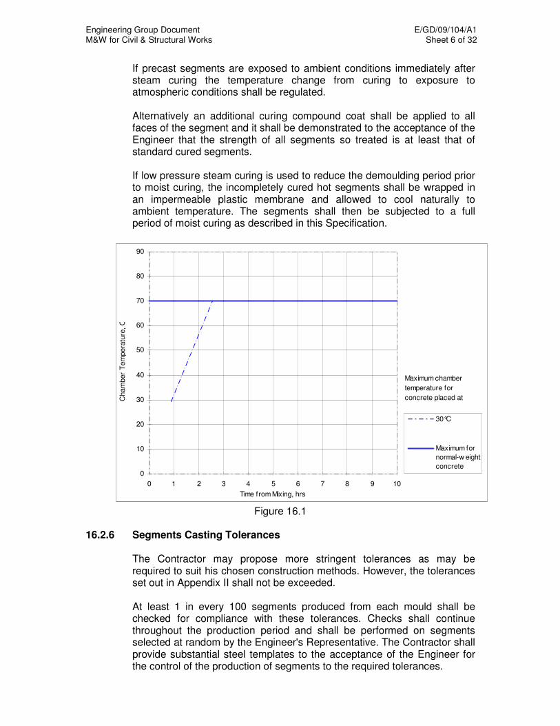
Engineering Group Document E/GD/09/104/A1 M&W for Civil & Structural Works Sheet 6 of 32
If precast segments are exposed to ambient conditions immediately after steam curing the temperature change from curing to exposure to atmospheric conditions shall be regulated. Alternatively an additional curing compound coat shall be applied to all faces of the segment and it shall be demonstrated to the acceptance of the Engineer that the strength of all segments so treated is at least that of standard cured segments. If low pressure steam curing is used to reduce the demoulding period prior to moist curing, the incompletely cured hot segments shall be wrapped in an impermeable plastic membrane and allowed to cool naturally to ambient temperature. The segments shall then be subjected to a full period of moist curing as described in this Specification.
0
10
20
30
40
50
60
70
80
90
0 1 2 3 4 5 6 7 8 9 10
Time from Mixing, hrs
Ch
am
ber
Tem
pe
ratu
re, C
30°C
Maximum for
normal-w eight
concrete
Maximum chamber
temperature for
concrete placed at
Figure 16.1
16.2.6 Segments Casting Tolerances
The Contractor may propose more stringent tolerances as may be required to suit his chosen construction methods. However, the tolerances set out in Appendix II shall not be exceeded. At least 1 in every 100 segments produced from each mould shall be checked for compliance with these tolerances. Checks shall continue throughout the production period and shall be performed on segments selected at random by the Engineer's Representative. The Contractor shall provide substantial steel templates to the acceptance of the Engineer for the control of the production of segments to the required tolerances.
Engineering Group Document E/GD/09/104/A1 M&W for Civil & Structural Works Sheet 7 of 32
16.2.7 Grout Holes
Unless they are to be used for the injection of primary grout the grout holes shall terminate short of the outer surface of the segment. Each grout hole shall include a threaded socket cast into the segment unless otherwise accepted by the Engineer and a threaded grout plug with a hydrophilic washer. The hydrophilic washer shall only be included if the hole is used by the Contractor for grouting. The internal diameter of the socket shall be not less than 50mm. The socket shall be arranged such that the grout plug in its final position does not protrude into the tunnel beyond the inner surface of the segment. The head of the plug shall incorporate a suitable means by which it can be tightened and removed, for example a square or hexagonal socket or head, but shall be of a design that cannot trap water when inserted below axis level. The design of the socket, plug, washer and any ancillary material such as grease or other coating to the threads shall be to the acceptance of the Engineer. All sockets shall be of metallic type. The assembly shall have a design life of not less than 120 years. Grout sockets and plugs shall be capable of withstanding the ground water pressure and any additional pressure caused by grouting without leakage. In any case, they shall be able to resist a liquid pressure of not less than 7 bar above atmospheric pressure without leakage. The clear distance between the grout socket or hole and the reinforcing bars in the segments shall be not less than the specified concrete cover to the reinforcement. Immediately after the lining is erected each grout plug shall be fully screwed into place. When the grout plug is in place, no water or grout shall seep into the tunnel from around the outside of the socket, from between the grout plug and the socket or through the grout plug. When a grout hole is used for secondary or tertiary grouting it shall be extended through to the exterior surface of the segment by drilling in a manner that does not cause damage to the concrete beyond the intended diameter of the hole. The diameter of the drilled hole and the means of drilling shall be to the acceptance of the Engineer. Upon completion of the Contract the Contractor shall leave each grout hole in a condition in which the grout plug can be removed without damage to it or to any part of the socket or the tunnel lining segments, the grout hole can be drilled out, grouting can be carried out and the grout plug replaced such that all leaks are sealed.
Engineering Group Document E/GD/09/104/A1 M&W for Civil & Structural Works Sheet 8 of 32
16.2.8 Segment Identification
The following information shall be cast in to the internal (concave) surface of all segments or shall be incorporated on a bar code fixed permanently to the inside face of the segment: i. LTA - followed by the Contract Number. ii. Date of Production iii. Mould Number iv. Ring Type e.g. – Left hand taper or right hand taper v. Segment Type e.g. - Key (S1L or S1R), S2L, S2R, S3, S4 and S5 vi. Reinforcement Type Where used, the materials and system for bar coding shall be to the acceptance of the Engineer and shall not result in any material which might be deleterious to the long term appearance or durability of the segment from being fixed to the face of the segment.
16.2.9 Surface Preparation and Repair (Casting Yard) All blowholes, spalling of edges and gasket grooves and minor damage in the formed concrete surfaces shall be filled with a fresh specially prepared cement mix whilst the concrete is still green to produce a Type C finish to SS CP 65. Cement mortar shall be used incorporating Styrene Butadiene Rubber (SBR) or Polyvinyl Acetate (PVA). Alternatively, polymer modified cement based mortar shall be used in accordance with the requirements of SS CP 65. Surface preparation is not generally required but contamination such as mud, dust, mould oil, grease or other substances that may adversely affect the bond of the coating to the concrete shall be removed by hosing and/or detergent scrubbing and/or high pressure water jetting as may be required, all to the acceptance of the Engineer. All projecting fins of hardened grout such as may occur at the joints between the sides and base of the mould shall be removed by grinding. All segment repairs carried out at casting yard shall be recorded and reported to the Engineer. Repairs shall be carried out in accordance with the requirements in Appendix I. Sufficient time shall be allowed for the cementitious mortar to cure prior to epoxy coating of the segment surfaces.
Engineering Group Document E/GD/09/104/A1 M&W for Civil & Structural Works Sheet 9 of 32
16.2.10 Rejection of Segments
All segments containing honeycombing shall be rejected. Segments containing cracks shall be rejected unless otherwise accepted by the Engineer.
16.2.11 Trial Assembly All units of the same type shall be interchangeable and the dimensions for each unit shown on the Drawings shall be accurately reproduced within the tolerances previously specified. In order to check on the matching, spacing of bolt holes and interchangeability of bolted segments and before bulk manufacture is commenced the Contractor shall assemble and bolt together on a flat level base accepted by the Engineer segments to form three rings of each type of primary lining and for each mould set in the presence of and to the acceptance of the Engineer. The rings are to be built one above the other and the radial joints staggered by two thirds of a segment. No packing or gaskets are to be used in the joints between segments in these trial rings. The lowest ring shall be retained as a master ring for the duration of the Contract. The segments forming this ring may be selectively hand picked and the segments for the other two trial rings shall be picked at random. From time to time, as the Engineer may direct, segments selected at random shall be built to form rings on the master rings to ensure that tolerances and interchangeability of segments are being maintained.
16.2.12 Handling
The Contractor shall make all arrangements for the proper delivery, handling and stacking of the segments. Segments shall be handled in such a manner as to avoid overstress or damage, and so as to preserve the protective coating. Segments which are found on inspection to be damaged or substandard on delivery to the Site shall be indelibly marked and removed from the Site.
16.2.13 Grouting of Lining A suitable grout mix shall be proposed for each set of ground conditions to be encountered along the tunnel drive. The grout shall be sufficiently fluid as to ensure that it flows freely under pressure into all parts of the space to be filled. All grout mixes and injection methods shall be submitted to the Engineer for acceptance. Information given shall include:

Engineering Group Document E/GD/09/104/A1 M&W for Civil & Structural Works Sheet 10 of 32
i. mix designs ii. mixing and delivery systems which should be consistent with planned
maximum TBM advance rate iii. grout gel times iv. design cube strengths at the end of one ring construction cycle v. design cube strengths at specified times after placement vi. proposed operational and maximum grouting pressures with regard to
the vertical tunnel alignment vii. requirements for sampling and testing during production viii. theoretical grout volume including considerations for use of any TBM
copy cutters Site trials for each mix and delivery system shall be carried out prior to the commencement of tunnelling to demonstrate that the proposed system works with the adopted tunnelling method and plant. The trials shall also demonstrate the properties of each grout mix and its suitability for the ground conditions. During production strength testing of the primary grout at 1hour, 3 hours, and 6 hours after the time of placement shall be carried out at least once every five rings built or daily, whichever is more frequent. The test samples shall be taken from the TBM. The timing for testing may be extended beyond 6 hours if this reflects the actual time between injection and shoving. Other grouts shall be sampled and tested as appropriate for their use and to the acceptance of the Engineer. All primary grouts shall achieve a minimum cube strength of 50kPa before the next 'shove' commences and a minimum of 2MPa at 28 days. During production grout pressures shall be continuously monitored at the point of injection using in-line pressure gauges and shall be restricted to values not greater than 1.2 x total overburden. The amount of grout used shall be recorded, and if the quantity falls short of that required to fill the void, further investigation and grouting shall be carried out. Where accelerators are used they shall be incorporated at the point of injection of the grout and not beforehand. In tunnels driven with a closed face machine, primary grouting of the annular void behind the segments shall take place continuously and simultaneously through at least two upper quadrant grout ports as the shield progresses forward. The grout shall be injected automatically as the machine advances. In tunnels driven other than by closed face machine primary grouting may be by injection through the grout holes in the tunnel lining segments. Where this method is used the primary grout shall be injected behind each tunnel ring as the ring leaves the shield tailskin. In each case the void shall be completely filled.

Engineering Group Document E/GD/09/104/A1 M&W for Civil & Structural Works Sheet 11 of 32
Primary grouting shall be carried out to ensure that the annular void is completely filled. Grouting shall continue until at least both the minimum volume and minimum pressure criteria have been satisfied. Grout injected through the tunnel lining shall be forced through the grout holes provided in the lining by means of adequate pressure from a grouting pan in which provision is made for keeping the grout uniformly mixed, or by a positive action pump of a type accepted by the Engineer. The drilling shall be carried out in such a way as to avoid any ground loss. In the event that grout records indicate to the Engineer that a void or cavity is suspected the Contractor shall propose a method of investigating for such a void or cavity. Following the investigation the Contractor shall, if necessary, re-grout the tunnel lining to ensure all voids are filled. Investigation and re-grouting of the lining shall take place within 24 hours of the void being suspected, unless otherwise agreed with the Engineer. Following the discovery of one or more voids proof grouting may be required in areas directed by the Engineer to demonstrate no further voids exist. Secondary ‘crown’ grouting shall be carried out from the machine backup at every second ring. The Contractor shall submit proposals for this work for the Engineer’s acceptance prior to the commencement of tunnelling. The Contractor shall maintain grouting records including volumes and pressures for each stage of grouting. These shall be submitted to the Engineer at the end of each shift. The Contractor shall also calculate a rolling 10 ring average grout take which he shall submit to the Engineer on a weekly basis. All these submissions shall be made in both hard and soft copy in formats acceptable to the Engineer. For grouts that rely on rheology, trial mixes shall be tested for the following, as a minimum: i. Grading curves: These should be obtained for the individual
constituents and the combined mix. ii. Cube Tests (compressive strength): Standard cubes, tested for
compressive strength in accordance with BS 1881 iii. Segregation: A sample of fresh mortar is prepared in a graduated test
cylinder. The bleed water volume and mortar volume are measured at 1, 2, 3 and 8 hours.
iv. Relaxation: Cylinders of mortar are made and cured for 15 and 45 days. After curing the cylinder is stripped and the sample placed vertically, unsupported. The height of the sample is measured at regular intervals up to 24 hours. Relaxation is reported as a loss of height of the mortar sample.
v. Wash-out test: A sample of fresh mortar is placed in a perforated container of known volume and mass. The container and sample are dropped through a 1 metre column of water five times within 15
Engineering Group Document E/GD/09/104/A1 M&W for Civil & Structural Works Sheet 12 of 32
minutes of mixing. The wash-out is calculated as the percentage loss of sample.
vi. Bleeding under pressure: The mortar is tested in a Baroid filter press for 7.5 minutes under 1 bar.
vii. Workability: Use either a standard slump cone or a Prepakt cone. viii. Cohesion. Measured using a laboratory vane apparatus. ix. Internal friction: A sample of mortar is prepared and fog cured at 23oC
until testing. The sample is placed in a triaxial cell and tested to determine apparent cohesion and angle of internal friction. The sample should not be consolidated or force saturated prior to testing.
The designer shall set limiting values for all of these tests. The designer shall also establish a quality control regime, including some or all of these tests, for the production grout. In order to confirm the effectiveness of the grout used (whether dependant on rapid setting or rheology), the change in level of the invert of at least five of the first 20 production rings, and at least 1 ring in 50 thereafter, shall be measured. Measurement points shall be installed immediately after primary grouting for that ring, and shall be measured before and after shoving for the next five rings. Movement under the weight of the back-up shall also be measured. Unless accepted otherwise by the Engineer, the vertical movement of the ring at any time from completing primary grouting
to the end of the back-up shall not exceed ± 5mm. The grout shall remain effective for the design life of the tunnel. The grout shall not degrade, shrink or lose strength to an extent that the tunnel would be damaged or become unserviceable as a result.
16.2.14 Construction Tolerances
After grouting, the ring of segments of tunnel lining shall conform to the following tolerances: i. The centre of the ring of segments shall not depart from its design
position by more than 50mm. ii. Every internal diameter shall not be different from the design diameter
by more than 25mm. iii. The internal profile of the lining shall not depart from its design position
by more than 62.5mm (combining i and ii above). iv. The square and plumb (pitch and yaw) of the lining shall not differ by
more than 20mm from the design value measured over the internal diameter horizontally and vertically or by more than 20mm from the attitude of the shield.
v. The leading edge of the lining shall not be out-of-plane by more than 6mm. The Contractor shall propose a system that can check for out-of-plane.
vi. The absolute roll of the lining shall be no greater than ±40mm measured from a horizontal diameter. The roll of each ring in relation to the previous ring shall be no greater than can be accommodated within the limitations of bolt hole clearances.
Engineering Group Document E/GD/09/104/A1 M&W for Civil & Structural Works Sheet 13 of 32
vii. Lips and steps between segments at radial and circumferential joints shall not exceed 5mm.
A non-conformance report shall be raised by the Contractor for any ring which is found to be out of tolerance after erection and grouting. Any ring or part of a ring which does not satisfy these tolerances shall, if the Engineer so directs, be rebuilt by the Contractor. At the locations of cross passages and other works where there is the possibility of additional deformation during breakout and subsequent construction the Contractor shall support the lining so that the tolerances are not infringed.
16.2.15 Re-Alignment of Out-of-Tolerance Lining The Contractor shall propose immediate remedial actions to bring the tunnel ring centre into tolerance. The Contractor shall stop the TBM advance in the event the tunnel drive is out of tolerance by 5mm and no satisfactory remedial action is proposed and accepted by the Engineer. The Contractor may propose a re-alignment to the railway to correct an out-of-tolerance tunnel drive. In exercising this proposal, it is the responsibility of the Contractor to demonstrate that: i. Required clearances to structure gauge are maintained ii. The re-alignment does not deteriorate the intended operational
characteristics of the line. The location of any chainage jump due to the re-alignment shall be located at station centre.
16.2.16 Segment Repair in Tunnel
All segment repairs shall be carried out to the acceptance of the Engineer. Detailed records shall be kept of each repair noting the position and type of repair and the materials used. Materials shall be submitted to the Engineer for acceptance. All segment repair materials shall be tested prior to use in the tunnels to ensure their workability and colour compatibility with the segmental lining.
16.2.17 Caulking Grooves and First Stage Concrete All caulking grooves shall be thoroughly cleaned. All caulking grooves below 1st and 2nd stage concrete level shall be maintained as open channels to prevent water under pressure from acting to lift the track slab. This may be done by the installation of channelling in the caulking grooves or by some other means. The final method and details shall be to the acceptance of the Engineer. A testing regime shall
Engineering Group Document E/GD/09/104/A1 M&W for Civil & Structural Works Sheet 14 of 32
be proposed to the acceptance of the Engineer to demonstrate that open channels have been achieved. Crack inducers shall be proposed in the 1st stage concrete at a maximum interval of 10 rings.
16.2.18 Database of As-Built Lining As part of the Project Quality Plan, the Contractor shall maintain a database of all as-built dimensions and conditions of the tunnel lining. For every ring built, the database shall include the following: i. diametric dimension of the lining vertically, diagonally (2 nos.) and
horizontally ii. maximum size of steps at each radial joint iii. maximum size of steps at each circumferential joint with arc length for
any step exceeding 5mm iv. position of key v. maximum roll of ring compared with adjoining ring vi. position, dimension and description of any crack vii. position and description of any other damage. The information shall be recorded for each ring when it is no more than 30m from the last ring built. Information shall be recorded in a format acceptable to the Engineer and both hard copy and soft copy in a format acceptable to the Engineer shall be submitted to the Engineer every week or at such other time as the Engineer may request. The production of the database shall not relieve the Contractor from the need to produce a non-conformance report for any ring built outside the requirements of this Specification.
16.3 FIXTURES AND COATINGS FOR SEGMENTAL LINING 16.3.1 General Requirements for Gaskets
All segments shall be provided with a composite gasket water sealing system consisting of a co-extruded elastomeric carrier and hydrophilic rubber as facing material. The minimum thickness of the hydrophilic rubber shall be 1mm. The system shall be designed, tested and installed to the acceptance of the Engineer and shall comply with the following requirements. The hydrophilic facing material must be compressed before annular grouting is carried out. Unless otherwise accepted by the Engineer, the elastomeric material shall be an EPDM (Ethylene Propylene Diene Monomer) formulated to provide good retention of elasticity and low stress relaxation properties.

Engineering Group Document E/GD/09/104/A1 M&W for Civil & Structural Works Sheet 15 of 32
At least three samples of the proposed EPDM material shall be subjected to accelerated ageing tests at elevated temperatures of 60oC, 80oC and 100oC. The elastic modulus of the degraded specimens shall be measured at intervals of 1, 7, 14, 28, 56 and 90 days. Based upon the results of these tests the projected elastic modulus of the EPDM material after a 120 years design life at a service temperature of 25oC shall be calculated in accordance with Arrhenius’s Theory. This projected value shall not differ by more than 35% from the short-term elastic modulus of the fresh material when measured at a temperature of 25oC. At least three further samples of the proposed EPDM material shall be subjected to accelerated stress relaxation tests at elevated temperatures of 60oC, 80oC and 100oC. The residual compressive stress in the degraded specimens shall be measured at intervals of 1, 7, 14, 28, 56 and 90 days in accordance with the general procedural requirements of DIN 537 Sept 85 Method B or other procedure to the acceptance of the Engineer. Based upon the results of these tests the projected residual compressive stress in the EPDM material after a 120 years design life at a service temperature of 25oC shall be calculated in accordance with Arrhenius’s Theory. This projected residual compressive force shall not be less than 65% of the short-term compressive force of the fresh material when measured at a temperature of 25oC. The hydrophilic facing material shall be a vulcanised polychloroprene rubber formulated with hydrophilic polymers. The formulation of the hydrophilic material shall provide good water expansion properties with the minimum of leaching of the active materials. The hydrophilic material shall exhibit at least a 6-times volumetric swelling when immersed for a period of 28 days in clean tap water. Further the hydrophilic material shall exhibit at least a 4-times volumetric swelling when immersed for a period of 28 days in a salt water solution containing 1% chloride ions and 0.5% sulphate ions measured as SO3. A sample of the hydrophilic material shall also be weighed and then freely immersed in distilled water for a period of 28 days. On completion the sample shall be oven dried at 50oC until no further weight change is recorded. The percentage weight change after the wetting and drying cycle shall not exceed 6% of the original weight. Both the EPDM and hydrophilic material shall be resistant to acidity at least as severe as pH 5 and shall be unaffected by sustained exposure to operating temperatures of up to 40oC. The Contractor shall provide the Engineer with a detailed statement regarding the durability of the proposed materials demonstrating their ability to meet the specified performance criteria for the design life of the structure. The statement shall provide any further information and test data relevant to the water absorption, long term swelling capacity, relaxation, chemical resistance and ageing of the materials. In particular the materials shall be resistant to attack from all substances in the ground and
Engineering Group Document E/GD/09/104/A1 M&W for Civil & Structural Works Sheet 16 of 32
groundwater at the concentrations found in the site investigation, to the alkalinity of the tunnel lining concrete and tunnel grout and shall be resistant to microbiological attack. The statement shall include a list of substances known to be deleterious to the materials, together with an analysis of the risk of contact with such substances. The Contractor shall ensure that the grout is not permitted to penetrate to the gasket location as this would impair its function. The selected gasket shall have a proven reputation for satisfactory performance in tunnels with similar ground water pressure. The Contractor shall design, supply and install the gaskets and any grooves into which or the surfaces onto which they fit to the acceptance of the Engineer. They shall be in the locations shown on the Drawings or as otherwise accepted by the Engineer. The Contractor shall carefully detail the size and depth of the gasket groove to ensure that it is of sufficient volume that when the segment faces are fully closed, the volume of rubber in the gasket can be housed within the groove. Unless otherwise accepted by the Engineer the volume of the gasket groove shall be at least 5% larger than the volume of rubber in the gasket. Where compressible joint packings are systematically incorporated between the joint surfaces the compressed thickness of the packing may be considered in the calculation of the volume of the gasket groove. The gaskets shall form continuous loops (frames) around the segments and shall be bonded to the concrete surface with adhesives recommended by the gasket manufacturers and following the procedures recommended by the adhesive manufacturers. The design of the gaskets shall be such as to render them inherently resistant to damage during transport and erection of the linings. The Contractor shall provide drawings of the principal dimensions and proposed tolerances on the gaskets. The drawings shall include the dimensions and positions of the gasket grooves or mounting surfaces. The corners of the gaskets shall be moulded to the appropriate corner angles of the segments. Detailed drawings of all segments shall be supplied by the Contractor to the gasket manufacturer. The corners of the gaskets shall be designed to ensure that the volume of rubber remains constant and that they have the same load and closure forces as the main body of the gasket. The corners of the gaskets shall be subject to full opening and closure tests to ensure the integrity of each joint. The gasket manufacturers shall be ISO 9001 (or equivalent national or international quality standard) certified and shall have in place detailed procedures to ensure the quality control of the gaskets at each stage of their testing and manufacture.
Engineering Group Document E/GD/09/104/A1 M&W for Civil & Structural Works Sheet 17 of 32
The Contractor shall prepare detailed works procedures to cover the installation of the gaskets and the storage of segments to which these have been fitted. These procedures shall be developed from the requirements of this Specification and incorporate installation details determined from the literature of the manufacturers of the gasket and adhesive. These procedures shall be prepared for the information of the operatives engaged on the Works and as far as practical shall be in the format of cartoon drawings and diagrams illustrating the correct action at each stage of the procedure. They shall include details of the accuracy with which the gaskets have to be installed in order to obtain the performance achieved in the tests. The method statement shall include details of how the segments will be installed in the tunnel without damage to, contamination of or displacement of the gaskets. Lubricants shall be proposed and used to the acceptance of the Engineer. Any lubricants shall be as recommended by the supplier of the gaskets. Prior to commencing manufacture of the gaskets prototype samples for each segment type shall be subject to fitting trials in order to determine the optimum tension for the gaskets. Each gasket shall be lightly tensioned to ensure that it grips the segment and fits snugly into the gasket groove. Corners of the gasket shall be square and tight fitting. These trial fittings shall be conducted by representatives of the gasket manufacturer and witnessed by the Engineer. Installed gaskets shall be free from surface imperfections, voids, inclusions or flow marks and other defects which would impair satisfactory performance. The surfaces shall be smooth. Fabrication joints in the gasket material shall be made with such accuracy as not to impair satisfactory performance in the tunnel environment. Prior to installation gaskets shall be stored under cover in a dry storage area in an undeformed relaxed condition at moderate temperatures and protected from direct sunlight. They shall be protected from circulating air and shall not be stored near equipment that can generate ozone (such as electric motors). The gaskets shall be kept clean, particularly avoiding contact with metals, solvents, oil and grease. The Contractor shall specify the type of wrapping and packing he proposes for the gaskets and the conditions under which they will be stored. All deliveries shall be marked with the date of production and early deliveries shall be used first to minimise storage times. If cleaning of gaskets is necessary only those approved for such use by the manufacturer of the gaskets shall be accepted. Fitting of the gasket frame shall commence at the radial joint surfaces neatly pressing the gasket into the groove or on to the surface by hand. The circumferential joint surfaces shall then be fitted starting from the middle and working towards the two corners on each face. Care shall be taken to ensure that the frame is accurately located and that the corners

Engineering Group Document E/GD/09/104/A1 M&W for Civil & Structural Works Sheet 18 of 32
are neither distorted nor loose. The frame may be lightly hammered into position using a rubber hammer and shall then be pressed onto the surface for a minimum period of five minutes until the adhesive has hardened. Unless otherwise accepted by the Engineer gasket frames shall not be installed onto the segment prior to seven days before their installation into the tunnel. Each completed segment shall be inspected for correct seating of the frame and uniform adhesion prior to storage. Completed segments shall be protected from precipitation and direct sunlight. Completed segments shall be stored under covered conditions or tarpaulins prior to installation in the tunnel.
16.3.2 Performance Testing of Gaskets The Contractor shall provide a test rig or rigs and carry out tests of the gaskets in Singapore to demonstrate the watertightness of the system. Tests shall be witnessed by the Engineer. The gasket-mounting surfaces of the test rig platens shall be fabricated or finished in cement mortar and shall incorporate grooves and/or mounting surfaces of the same dimensions as those on the lining segments. The gaskets shall be installed in the same manner as those on the lining segments using similar adhesives and installation procedures. A series of tests shall be conducted for each gasket type. The tests shall be carried out using water with chemical content equivalent to the concentrations found in the ground water in the site investigation which will most impair their performance. Each test series shall comprise the testing of a straight joint, a ‘T’ joint such as occurs at the intersection of a radial joint and a circumferential joint in the tunnel lining and a cross joint. The configuration of the test rig shall be such that it can accurately simulate the combination of gaps, steps and lips defined herein. The gap between the faces of the test pieces, representing gaps in the joints of the tunnel lining, shall be 5mm greater than the theoretical value calculated from the shape of the joint surfaces and from the thickness of any packing which is to be used. The tests shall be performed with a lateral offset of 10mm at the groove in the following configurations. Straight joint : one side offset ‘T’ joint : one side of intersecting joint offset Cross joint : one side of intersecting joint offset The gasket test pressure shall be defined as twice the design hydrostatic head. Unless otherwise accepted by the Engineer, the design hydrostatic head shall be considered to be the maximum distance between the invert of the tunnel and the ground surface.

Engineering Group Document E/GD/09/104/A1 M&W for Civil & Structural Works Sheet 19 of 32
The test pressure shall be applied in 1.0 bar increments by means of a variable pressure reflux valve or other stabilising device, capable of maintaining the applied pressure within 1% of the desired pressure at each pressure increment. The pressure shall be held for 15 minutes at each increment. The final pressure shall be held for 24 hours during which no visible sign of leakage shall be noticeable. If the Contractor envisages that gaps larger than those indicated above will occur in the tunnel, due for example to the use of thicker packings, then the Contractor shall carry out tests with an appropriately larger gap. Only those gaps shall be used in the Works that are covered by a representative test. The Contractor shall demonstrate that when the joints are closed to the fullest extent that will occur in the Works, no damage will be caused to the tunnel lining segments by the gaskets. “The fullest extent that will occur in the Works” shall be deemed to be: i. In the circumferential joints - Closed to the maximum extent that will be
allowed by the packings in the joints. ii. In the radial joints - Joint closed by the maximum extent that will be
allowed by the gaskets. The Contractor shall provide evidence that with smaller joint gaps and offsets than those specified above, the water pressure that can be withstood by the gaskets will not be less than the specified test pressures. This evidence can be in the form of further testing or certified results of previous tests on identical gaskets. For hydraulic materials test results of volumetric change with time in clean fresh water shall be provided by the Contractor. The Contractor shall prepare a prototype key/top plate test rig and demonstrate that when fully compressed into the gasket groove the gasket surfaces may slide relative to each other without causing slippage of the gasket within the groove or on the mounting surface, undue distortion of the corners of the gasket or, delamination of the hydrophilic facing material from the EPDM carrier. The same lubricant material that will be used in the tunnel during the erection of the segments shall be employed during the test. The test shall be repeated at increments of lipping between segments of 0, 5 and 10mm. The Contractor shall prepare steel loading platens at least 100 mm in length provided with grooves or mounting surfaces of the same dimensions as those on the lining segments. The gaskets shall be installed in the same manner as those on the lining segments using similar adhesives and installation procedures. The Contractor shall determine the force required to compress the gasket during erection and prepare graphs of load and deflection. The Contractor shall ensure that the segment erector has sufficient power to compress the gasket on the radial joint
Engineering Group Document E/GD/09/104/A1 M&W for Civil & Structural Works Sheet 20 of 32
surface and confirm that the tunnel lining bolts have adequate strength to provide and maintain this force. The Contractor shall also demonstrate by appropriate testing that when fully compressed, the gasket corners do not deform to such an extent that its sealing capacity reduced to less than the minimum requirement as defined herein.
16.3.3 Packings The type and thickness of packing shall be proposed by the Contractor to suit his construction tolerances and methods and to avoid damage to the rings. Packing may be incorporated into all circumferential joints so as to cushion the segments against excessive stresses under shield jack loading. Packing may also be used to correct the plane of the rings but not for corrections to square and plumb or for negotiating curves. Packing shall be formed from fire retardant material and shall not give off toxic fumes in the event of a fire. Packing shall generally be glued to the surface of the segments prior to erection, though insertion of packing for correction of plane will be permitted during segment erection provided that safe working practices are employed. Any glue used shall be non-flammable and suitable for use in a confined space irrespective of the ventilation provided in the tunnel. Packing thicknesses shall be limited to those for which appropriate tests have been carried out on the composite gaskets. The packings shall not permit rotation of the rings under the influence of torque applied by the shield of a magnitude that is detrimental to the performance of the lining.
16.3.4 Threaded Fasteners, Washers Grout Plugs and Cast-In Fixings Cast-in fixings and grout plugs shall be of mild steel complying with BS 7668 and BS EN 10029, 10113, 10155 and 10210. Threaded fasteners and washers shall be of a steel grade as determined by the designer. All threads shall be cut cleanly to comply with BS 3643 standard threads. Non-threaded steel fixings and fittings shall be galvanised in accordance with BS 729 after manufacture. Threaded items shall be galvanised in accordance with BS 7371 Part 6 after manufacture. As an alternative to galvanising, sherardizing to BS 7371 Part 8 Class S1 may be used for threaded items.

Engineering Group Document E/GD/09/104/A1 M&W for Civil & Structural Works Sheet 21 of 32
After coating all nuts shall be free fitting and able to be threaded on to bolts by finger pressure. Grout plugs shall be able to be threaded in to the grout sockets by hand. As an alternative to mild steel, SG iron may be used for cast-in sockets, bolt pockets and grout plugs. SG Iron grout plugs for threaded sockets shall be malleable cast iron taper screw plugs conforming to BS 143 and 1256 and BS EN 10242 and the threads shall conform to the requirements of BS21 Pipe Threads. The size shall be chosen by the Contractor to the Engineer’s acceptance. The heads and threaded parts shall be solid. The malleable iron from which the plugs are made shall comply with BS EN 1562, Grade 300/6. The thread of the plugs shall be coated with grease after manufacture. The Contractor may propose other materials, subject to the acceptance of the Engineer. The length of each lining bolt shall allow for two washers of a type accepted by the Engineer and for all adjustments required in the alignment of the tunnels. When fitted in position the bolt threads shall be exposed for at least 3mm clear of the nut. This applies even where the maximum build tolerances have all been used in the erection of the lining. Lifting sockets, where used, shall be subjected to pullout tests. A minimum of 2 trial tests before production and a minimum frequency of 1 test per 2000 sockets during production shall be carried out. The test shall demonstrate a factor of safety of 3 against failure at the design pullout load. The design pullout load shall be equal to the dead load of the largest segment in the ring. An additional test shall be carried out on another socket for every test that does not demonstrate this factor of safety to the satisfaction of the Engineer. Tested segments shall not be incorporated in the works. If the Contractor proposes the use of a mixture of different metals for the fixtures and fittings he shall, as part of his proposal, demonstrate to the acceptance of the Engineer that their long-term durability is not compromised. In particular the Contractor shall demonstrate that where two different finishes or metals are to be left in contact or in close proximity with one another in the permanent works there is no risk of accelerated corrosion or other deterioration.
16.3.5 Waterproof Coatings for Segments The outer (convex) surface of all segments together with all side faces, gasket recesses, caulking grooves and insides of bolt holes and grout holes shall be painted with a solvent free or water based emulsion epoxy coating. All epoxy materials shall be stored, mixed and applied in strict accordance with the recommendations of the coating manufacturer. Surfaces shall first be primed with either a penetrative primer, which may be non-pigmented, or a thinned coating of the under coat of epoxy.

Engineering Group Document E/GD/09/104/A1 M&W for Civil & Structural Works Sheet 22 of 32
The waterproof coating shall then be applied in at least two further coats. When applying one coat of epoxy coating over another the top coat shall be applied to the preceding coat within the time period for overcoating stipulated by the manufacturer and generally in a direction perpendicular to the preceding coat. The top coat shall be a contrasting colour to the preceding coat. When tested in accordance with DIN 1048 the epoxy coated surface shall
have a permeability of <1 x 10–17 m/s. When tested for Moisture Vapour Transmission the epoxy coating shall
have a Diffusion Coefficient of >3000 and an Equivalent Air Layer
Thickness of <4.0m. The test method for water vapour permeability shall be in accordance with BS EN 1062 “Paints and Varnishes, Coating Materials and Coating Systems for Exterior Masonry and Concrete, Part 2 Permeability to Water Vapour”. When tested in accordance with ASTM D4541 for adhesive strength to the substrate using a 50mm diameter dolly the epoxy coating shall have a minimum adhesive strength of 1.5MPa. When tested in accordance with BS 476: Part 7 the epoxy material shall achieve a Class 1 rating for flame spread. When tested in accordance with BS 6853: Appendix B Clause B9.3 the epoxy material shall exhibit no flaming of the surface. The Contractor shall maintain records that show the material consumption of the epoxy coating per segment. At all times these records shall be available to the Engineer. The dry film thickness of the epoxy coating shall be checked at the discretion of the Engineer by either minor destructive or non-destructive methods. The minimum thickness shall be 200 microns. The Contractor shall provide proof of the depth to which the primer has been absorbed into the substrate in conditions identical to those found at the site where the coating will be applied during production. This evidence shall be in the form of conventional petrographic analysis or other method to the acceptance of the Engineer. Under the following circumstances, the applied epoxy coatings shall be deemed to fail to comply with the Specification: i. Rain damage ii. Sagging or running is evident as a result of the application of an
excessive amount of epoxy coating iii. Maximum interval between successive coats as specified by the
manufacturer has been exceeded iv. The coating surface has been contaminated prior to full curing v. Blistering or surface delamination of the coating occurs

Engineering Group Document E/GD/09/104/A1 M&W for Civil & Structural Works Sheet 23 of 32
Where the coating does not comply with the Specification the coated concrete shall be abraded to provide a smooth clean surface and two coats of material shall then be re-applied in a manner which is to the acceptance of the Engineer. Where the dry film thickness is less than the minimum specified requirement a further coat shall be applied in accordance with the manufacturer’s instructions to achieve the specified thickness. The additional coat shall comply with the overcoating requirements. The Contractor shall prepare and submit a method statement for a trial application to the acceptance of the Engineer. The Contractor shall give the Engineer 48 hours notice of his intent to commence the trial application. A concrete panel shall be coated in accordance with the Specification and the accepted method statement. The coated surfaces shall then be inspected for compliance. The Engineer will only accept the proposed method of application of the coating if the Contractor has demonstrated competence in using both the epoxy coating material and the application equipment. Production application shall not proceed without the acceptance of the Engineer. If the coatings are deemed not to comply the coating operation shall be repeated using a fresh concrete panel until compliance with the Specification has been demonstrated and the method statement amended as appropriate. The work practices adopted during the trial shall be adopted for all subsequent coating application operations. The Contractor shall supply material safety data sheets for all components of the epoxy coating. The Contractor shall store, handle, mix and apply the coating in strict accordance with the material safety data sheets. Particular care shall be paid to all health, safety and environmental statements contained in the material safety data sheets. Products which are excess to requirements or which have exceeded their shelf life or which the Engineer has not accepted for whatever reason shall be disposed of in a safe and controlled manner. Empty packaging may contain harmful residues. In any case disposal shall be arranged through a licensed waste contractor in accordance with the current local waste disposal regulations. The properties of the epoxy resin coating shall be as follows: i. Pot life at least 30 minutes at 30oC ii. Safe from exposure to rain after a minimum of 4 hours of storage at
30°C

Engineering Group Document E/GD/09/104/A1 M&W for Civil & Structural Works Sheet 24 of 32
iii. Solids content minimum 50%, maximum 55% by volume. This shall be confirmed by the Contractor with an independent test report from an accredited laboratory
iv. A contrasting colour for each coat shall be used. Colours are to be to the acceptance of the Engineer
v. Coverage rate 200 to 250 g/m2 per coat to provide a minimum total dry film thickness of 200 microns
vi. Fully compatible with the gasket adhesive Alternative specifications may be proposed by the Contractor for the acceptance of the Engineer.
16.4 CAST IN-SITU CONCRETE LININGS 16.4.1 General
Materials and additives shall suit the special requirements for placing in a tunnel environment, but shall otherwise comply with Chapter 11: Concrete and Reinforcement. Reinforcement shall comply in all respects with Chapter 11: Concrete and Reinforcement
16.4.2 Formwork Formwork shall comply with Chapter 11: Concrete and Reinforcement. Effective devices shall be used to hold adjacent edges or ends of formwork tightly together and in accurate alignment and in all cases to hold the formwork tightly against the concrete, which has been placed previously. Wherever it is necessary to position grout or other pipes through the forms, the Contractor shall drill holes through the forms at the required positions shown on the Drawings. Where the holes are to be provided for embedded grout pipes to a regular pattern, the holes shall be reinforced by suitable threaded bosses with flush fitting plugs. Where the holes are provided for a single pour they shall subsequently be filled flush to the face of the form before re-use. Formwork shall be provided with openings for concreting spaced at not more than 2.5m centres longitudinally in each side wall and in the crown. They shall be located at the springing line of the tunnel, in side walls, and alternately on each side of the tunnel centre-line in the crown. The openings shall be fitted with hinged doors, which fit flush with outer surface of the framework when closed. The dimensions of openings shall be approximately 0.6m wide x 0.4m high. The formwork shall be maintained at all times in good condition to maintain accuracy of shape, strength, rigidity, watertightness and smoothness of

Engineering Group Document E/GD/09/104/A1 M&W for Civil & Structural Works Sheet 25 of 32
surface. The Contractor shall keep all formwork clean and in good repair and shall supply and apply approved release agents to facilitate stripping. No part of any metal tie or spacer or pipe remaining permanently embedded in the concrete shall be nearer than 50mm to the finished surface of the concrete and the face cavity shall be so formed as to permit satisfactory filling. The Contractor shall carry out all corrective measures required by the Engineer to rectify work not constructed within tolerance. Where the tunnel is curved in plan or elevation the lining may be formed in a series of chords provided the minimum thickness of lining is maintained and provided that the tolerances on the position of the finished surface are not infringed.
16.4.3 Construction Joints Arch and invert construction joints shall be formed square to the line of the
tunnel. Water bars shall be of the hydrophilic and re-injectable grout hose type at all circumferential construction joints and as shown on the Drawings. Particular care shall be taken in the fixing in place of water bars to ensure that they remain in position square to the joint, without folding, when concrete is placed and vibrated around them. Site jointing of water bar shall be limited to simple butt joints which shall be made in accordance with the manufacturer’s instructions. Construction joints between adjacent arch and invert sections of the tunnel profile shall be similar to the above but shall be parallel to the line of the tunnel. All construction joints shall be watertight.
16.4.4 Preparations for Placing Concrete
The surfaces of the tunnel excavation or of previously placed concrete shall be thoroughly cleaned to remove all loose and foreign materials. Rock and concrete surfaces shall be cleaned by washing with a strong stream of air and water under pressure. Concrete and grout spillage from previous pours shall be broken out and removed. Reinforcement shall be cleaned of loose rust, mill scale and concrete spillage by the use of suitable steel wire brushes. Formwork shall be cleaned and freshly coated with a release agent immediately prior to concreting. Concrete shall not be placed in still or running water and shall not be subjected to the action of running water until after the concrete has hardened. Where water flows from surfaces against which the concrete is to be placed, it shall be excluded from the space to be filled with concrete by caulking, diverted by pipes, pans or other means and pumped from sumps until the concrete has hardened sufficiently to be unaffected by the action of water.
Engineering Group Document E/GD/09/104/A1 M&W for Civil & Structural Works Sheet 26 of 32
16.4.5 Concrete Placing Equipment
Concrete shall be placed by pumping equipment of suitable types with adequate placing capacity. Pumping equipment, storage hoppers, and delivery pipelines shall be lubricated at the start of each concreting operation and shall be thoroughly cleaned at the end of the operation.
16.4.6 Placing of Concrete
Concrete shall be transported from the mixer to the formwork as rapidly as practicable by methods which will prevent the segregation or loss of any of the ingredients and maintain the workability. Concrete shall be placed as close as possible to its final position and in continuous near level layers between construction joints located as approved or shown on the Drawings. The depth of the layers shall not exceed 500mm and each layer shall be compacted using mechanical vibrators specified below before succeeding layers are placed. Concrete placed in the tunnel arch shall be built up over the discharge line on the crown of the formwork, the end of the discharge line being kept well buried as the concreting advances. Care shall be taken to force concrete into all irregularities in the rock surfaces, or the surface of sprayed concrete temporary support and to fill completely the tunnel arch. All voids and spaces around the posts, ribs and wall plates of temporary support shall be filled as completely as practicable. Where concrete is placed against a waterproofing membrane, particular care shall be taken to avoid penetration of the membrane during the concrete placing operations. Cavities in the arch which, due to high overbreak, are above the general level of the crown of the tunnel shall be filled by subsequent cavity grouting, and adequate grout and vent pipes shall be embedded in the concrete. In the event of equipment breakdown or if for any other reason placing is interrupted, the Contractor shall thoroughly consolidate the concrete to a reasonable level or flat slope while the concrete is plastic. The concrete at the surface of such cold joints shall be cleaned with a high pressure air and water jet before the concrete hardens, to provide an irregular clean surface free from laitance. Prior to restarting concreting, the surface shall be wetted and a thin layer of cement sand mortar shall be vigorously brushed into the surface. Planned cold joints in permanent linings shall not be permitted. The work shall be so carried out that a sound dense lining is produced, admitting water only at the temporary drainage channels provided.
16.4.7 Compaction of Concrete Concrete shall be compacted by mechanical vibrators producing not less then 3600 vibrations per minute. Immersion type vibrators shall generally be used, supplemented, where necessary, by approved heavy duty formwork vibrators.
Engineering Group Document E/GD/09/104/A1 M&W for Civil & Structural Works Sheet 27 of 32
Where immersion vibrators are used, one vibrator shall be provided for every 6 cubic metres per hour of concrete to be compacted. Immersion vibrators shall be, wherever practicable, operated in a near vertical position, and the vibrating head shall penetrate and revibrate concrete in the upper portion of the underlying layer. They shall be withdrawn slowly to avoid the formation of voids and shall be carefully positioned to avoid contact of the vibrating head with the formwork. Particular care shall be taken with the compaction of concrete surrounding water bars to avoid honeycombing and to prevent the displacement of the water bar. Care shall also be taken to avoid damage to waterproof membranes and displacement of prefixed pipes, blockouts, bolts and the like. Formwork vibrators shall be used for compacting concrete in the tunnel arch above the highest openings in the formwork. They shall be operated at intervals of not more than 1.2m behind the advancing slope of the concrete in the shoulders and crown of the arch. The location and operation of the vibrators shall be carefully co-ordinated with the withdrawal of the discharge line so as to avoid settlement and flow of the concrete from the filled crown due to improperly positioned and timed vibration.
16.4.8 Curing of Concrete
All in-situ tunnel concrete shall be cured by either moist curing, or membrane curing. Curing shall be maintained for a period of 4 days from the time of placing.
16.4.9 Surface Finishes
The surface finishes to arch and walls shall be Class F2 as per Chapter 11: Concrete and Reinforcement.
16.4.10 Concrete Replacement and Repair
The Contractor shall submit his detailed method statement and procedures for concrete replacement and repair to the Engineer for acceptance prior to the implementation on site.
16.4.11 Grouting of Cast In-Situ Concrete Linings
At least 14 days after concreting, the lining shall be grouted at the lowest pressure necessary to fill any remaining voids behind the lining. Sufficient grouting and vent pipes shall be put into position prior to concreting.

Engineering Group Document E/GD/09/104/A1 M&W for Civil & Structural Works Sheet 28 of 32
Appendix I

Engineering Group Document E/GD/09/104/A1 M&W for Civil & Structural Works Sheet 29 of 32
Guidelines For Precast Segment Repair (Prior To Erection) • Edge Repair a. Sharp Edge b. Chamfered Edge c. At Corners
Table 1 - Guideline for Edge Repair
Action A (mm) B (mm) C (mm)
No repair < 5 < 5 < 5
Repair with Cementitious Mortar
5 - 50 5 - 50 5 - 70
Reject > 50
or rebar exposed
> 50
or rebar exposed
> 70
or rebar exposed
C
A
A B
B
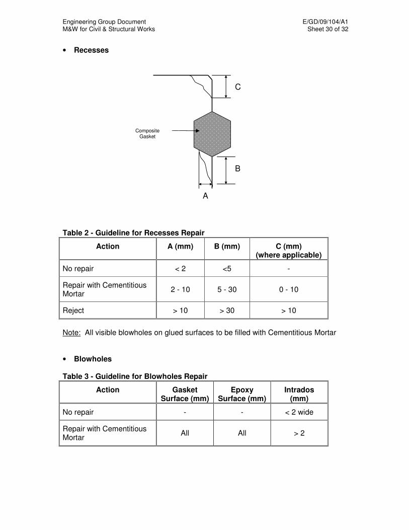
Engineering Group Document E/GD/09/104/A1 M&W for Civil & Structural Works Sheet 30 of 32
• Recesses
Table 2 - Guideline for Recesses Repair
Action
A (mm) B (mm) C (mm) (where applicable)
No repair < 2 <5 -
Repair with Cementitious Mortar
2 - 10 5 - 30 0 - 10
Reject > 10 > 30 > 10
Note: All visible blowholes on glued surfaces to be filled with Cementitious Mortar • Blowholes Table 3 - Guideline for Blowholes Repair
Action Gasket Surface (mm)
Epoxy Surface (mm)
Intrados (mm)
No repair - - < 2 wide
Repair with Cementitious Mortar
All All > 2
C
B
A
Composite Gasket

Engineering Group Document E/GD/09/104/A1 M&W for Civil & Structural Works Sheet 31 of 32
Appendix II

Engineering Group Document E/GD/09/104/A1 M&W for Civil & Structural Works Sheet 32 of 32
Engineering Group Document E/GD/09/104/A1
M&W for Civil & Structural Works Sheet 1 of 44
CHAPTER 17
SPRAYED CONCRETE LINING FOR TUNNELS 17.1 GENERAL
17.1.1 Definitions
SCL is the abbreviation for Sprayed Concrete Lining.
17.1.2 Precedence and References
a) Other relevant Chapters of the Materials and Workmanship Specification should be referred together with this Chapter on SCL. In cases of apparent conflict or ambiguity, clauses presented in this Chapter shall take precedence over the clauses stated in other Chapters of the Materials and Workmanship Specification.
b) The Contractor’s attention is drawn to the following references (or guides) to ensure a safe SCL design and construction practice:
i) ICE design and practice guide: Sprayed concrete linings (NATM) for tunnels in soft ground (1996), published by Thomas Telford Publishing.
ii) Safety of New Austrian Tunnelling Method (NATM) Tunnels-A review of sprayed concrete lined tunnels with particular reference to London Clay (1996), published by the Health and Safety Executive.
17.1.3 General Requirements
a) The Contractor shall demonstrate to the Engineer that the management and all key staff employed for SCL works are capable of carrying out the works.
b) The Contractor shall propose to the Engineer for acceptance an experienced site team comprising, but not limited to, a Site Manager, engineers, foremen and operators for the SCL works. The Site Manager shall have at least ten years experience of a similar type and size of works. Other key staff involved in the SCL works shall have at least five years experience of a similar type and size of works. The Engineer explicitly reserves the right to reject the proposed staff, which are considered unsuitable in terms of the person’s insufficient previous working experience.
c) The designer of the SCL works shall have a permanent representative on site. The representative shall be well experienced in SCL works, knowledgeable of the design detail and capable of making changes to the design.
d) At least three months before the commencement of SCL works, the Contractor shall have obtained the acceptance of the Engineer for the design of the SCL works.

Engineering Group Document E/GD/09/104/A1
M&W for Civil & Structural Works Sheet 2 of 44
e) At least two months before the commencement of SCL works, the Contractor shall present to the Engineer for his acceptance a method statement describing the construction methods related to SCL works. This method statement shall include, but shall not be limited, to the following matters:
i) Method of excavation and spoil removal. And the details on equipment to be employed.
ii) Sequencing of excavation stages.
iii) Application of shotcrete and equipment to be employed.
iv) Preparation of construction joints.
v) Installation of other ground support measures.
vi) Construction supervision plan.
vii) Hazard analysis and risk assessment.
viii) Proposals for surface and subsurface monitoring, with the establishment of trigger, design and allowable values and procedures for the evaluation of monitoring results.
ix) Contingency plan and related measures and procedures for emergencies. The contingency plan shall address the interaction between construction processes with the evaluation process of monitoring results.
f) If for any reasons the approved design method of working is changed, then a Change Request Excavation and Support Sheet (CRESS) is to be raised.
g) The CRESS shall be prepared and endorsed by the Contractor’s Site Manager responsible for the SCL works, the design representative on site and the Authority’s representative on site. Unless all the three signatures are obtained, the proposals indicated on the CRESS shall not be implemented.
h) The CRESS shall address, but not necessary be limited to, the following matters:
i) Precisely which tunnel section (chainages) the CRESS is applicable to.
ii) The proposed change to the design.
iii) Proposed changes in the method of working related to ground support including staging of application of shotcrete layers and lapping of reinforcement.
iv) Trigger, design and allowable values applicable to affected monitoring instruments.
v) Changes to the monitoring to be installed in the section of tunnel.
vi) Measures to be taken during stoppage of works
vii) Other instructions relevant to the tunnel section

Engineering Group Document E/GD/09/104/A1
M&W for Civil & Structural Works Sheet 3 of 44
viii) Reference to relevant design drawings
i) The Contractor shall propose an appropriate format for the CRESS acceptable to the Engineer.
j) The Contractor shall hold daily site meetings with the Engineer’s Site Representatives, the Contractor’s Designer, all sub-contractors’ representatives, and any other relevant personnel to review the following, as a minimum:
• Daily work activities
• Instrumentation and monitoring
• CRESS
• Health and Safety
• Quality
k) SCL structures shall consist of a primary lining for initial ground support and a secondary permanent cast insitu concrete lining. Waterproofing membrane shall be installed between the primary and the secondary lining unless accepted otherwise by the Engineer.
l) All except the face being excavated shall be coated with a flash coat/layer (or sealing coat/layer) of shotcrete of not less than 50 mm in thickness.
m) Only the Wet Method of shotcreting shall be allowed on site.
17.2 EXCAVATION 17.2.1 General
a) Underground excavations shall comply with the widths, lengths and depths shown on the Drawings. Proper allowance shall be made for ground deformation and construction tolerances.
b) Excavation shall be carried out in a uniform and controlled manner to
create a minimum size of the opening. Methods for excavation and ground support shall be chosen such that overbreak is avoided.
c) Over-excavation shall be kept to a minimum, consistent with the need
to maintain the necessary clearance according to the Drawings. No ground shall protrude inside the theoretical excavation line shown on the Drawings. The Contractor is required to perform at regular intervals a careful and systematic survey of the actual excavation profile.
d) Any tunnel with any excavated diameter greater than 6 m shall be
constructed around a circular or near circular pilot tunnel.
Engineering Group Document E/GD/09/104/A1
M&W for Civil & Structural Works Sheet 4 of 44
17.2.2 Procedure
a) Excavation procedures shall be adapted to local ground conditions. In unfavourable ground conditions, the Contractor shall propose special excavation methods and specific procedures acceptable to the Engineer which he considers can meet the requirements of the particular ground conditions so as to achieve safe excavation conditions with minimum deterioration or loosening of the ground surrounding the excavation, or to avoid overbreak and limit negative effects on already installed primary lining.
b) Where special support measures such as forepoling may lead to
over-excavation, the Contractor shall ensure that the excavation profile is kept to the absolute minimum required to progress the Works.
c) Over-excavation or overbreak shall immediately be recorded prior to
placing additional shotcrete layers over the initial sealing layer. In case of ground mass instability, the recording of the overbreak shall not delay application of ground support elements. The Engineer shall be informed about occurrence, location, extent and reason for the excess excavation beyond the extent proposed in the Contractor’s method statement.
d) Over-excavation shall generally be backfilled by shotcrete. If
accepted by the Engineer, over-excavation may be backfilled by secondary lining concrete or other material such as concrete, grout or by a similar material.
e) Ground conditions may require excavation in a sequence different
from that shown on the Drawings or detailed in the Contractor's Method Statement. Where necessary or instructed by the Engineer, the Contractor shall carry out such excavations in stages in order to ensure stability and safety of the Works. In this case, a CRESS shall be raised.
f) The spacing of support arches, where required, shall be in
accordance with the Drawings.
g) After completion of the excavation of a particular construction stage, the Contractor shall immediately apply a sealing layer of shotcrete (minimum 50 mm thickness) to minimize or avoid deterioration of the ground due to exposure.
h) To ensure the safety and the security of the works, tunnel excavation
and primary lining application shall be continuous except as accepted otherwise in advance by the Engineer or required by other restrictions on working time. If the state of the work permits, interruptions shall be allowed at weekends and general holiday periods, provided that the works are secured in a safe condition. In this case, the Contractor shall submit for the Engineer’s acceptance a proposal of support measures intended to secure the Works during the shut-down period
Engineering Group Document E/GD/09/104/A1
M&W for Civil & Structural Works Sheet 5 of 44
including implementation and inspection procedures. The interruption shall not be allowed until all the support elements at all necessary locations have been completed including thickening the excavation face with shotcrete. Related to interruptions of the Works, the Contractor shall identify the change on a CRESS and also carry out any additional support measures requested by the Engineer.
i) Attention is drawn to the likelihood of intercepting earlier site
investigation boreholes during the excavations. The holes may or may not have been effectively sealed and could represent sources of ingress of water where they emerge into the underground opening. All steps necessary shall be taken to identify, seal and plug these voids quickly at an early stage and as far as possible away from the current excavation face.
17.2.3 Method
a) The excavation method shall be chosen as to minimise the settlement and disturbance of the ground mass to ensure the structural integrity of existing surface and underground structures in the vicinity of the Works.
b) The method used for the excavation shall be appropriate to the size
of the underground opening and to the prevailing ground conditions. In general, excavation shall be carried out using a roadheader or other suitable mechanical equipment (e.g. backhoe). Small openings shall be excavated by hand. Any mechanical equipment for underground excavation works and transportation shall be suitable for the work specified with respect to performance and current safety regulations, as well as for compliance with the requirements of the construction schedule.
c) Excavation methods shall at all times be subject to acceptance by the
Engineer.
d) Underground mechanical plant and equipment shall be powered by electricity, compressed air or diesel engine. Petrol engines are forbidden.
e) At the start of the underground excavation, the Contractor shall carry
out trials to demonstrate that the excavation methods, which he proposes to use, shall achieve the required performance. During the progress of the Works the excavation methods shall be varied, as necessary, to suit the conditions and to obtain the best practicable excavation shape and surface conditions.
f) The maximum length of excavation before installation of ground
support shall comply with the Drawings.
Engineering Group Document E/GD/09/104/A1
M&W for Civil & Structural Works Sheet 6 of 44
17.2.4 Excavation Tolerances
17.2.4.1 General
a) Based on the theoretical excavation line shown on the Drawings and on additional allowances listed below, the Contractor shall excavate a minimum excavation profile. The Contractor shall provide to the Engineer documentation to demonstrate that the excavated profile meets the required construction tolerances. Convex surfaces shall not be accepted. If convex surfaces occur, they shall be trimmed back prior to shotcreting.
b) The theoretical excavation line given on the Drawings does not
include allowances for the anticipated ground deformations defined as Deformation Allowances or tolerances related to excavation accuracy defined as Additional Excavation Allowance. It is the Contractor's responsibility to determine the minimum excavation profile by adding these allowances to the theoretical excavation line in the radial direction.
17.2.4.2 Additional Allowances
a) The Contractor shall add to the theoretical excavation line the Deformation Allowances which he shall evaluate for each underground structure by means of the ground-structure interaction analysis
b) To the theoretical excavation line, enlarged by the deformation
tolerances, the Contractor shall further add the Additional Excavation Allowance (over-excavation) needed to achieve the required theoretical shotcrete profile according to the Drawings. The additional excavation allowance shall depend on the Contractor's intended excavation and support measures and equipment (excavation accuracy) as well as the total thickness of the intended waterproofing system.
17.2.4.3 Survey
The excavation profile shall be carefully controlled at all times using tunnel survey profiling/scanning equipment and software, which shall be approved by the Engineer. This equipment shall be capable of providing information to the excavation teams as the excavation progress and shall not delay the excavation process." Where, in the opinion of the Engineer the excavation profile is considered small, the contractor may propose alternative method of excavation profile control.
17.2.5 Excavation Sequence
This Section shall be considered as a guideline for the selection of excavation sequences for typical tunnel cross sections. The design to be submitted by the Contractor shall define the required details for each
Engineering Group Document E/GD/09/104/A1
M&W for Civil & Structural Works Sheet 7 of 44
particular case of tunnel cross section, ground conditions, loads, and overburden.
17.2.5.1 Tunnels with Any Excavated Diameter Greater than 6m
The excavation sequence for tunnels with any excavated diameter greater than 6 m shall be as follows together with a circular or near circular pilot tunnel:
Heading: advance length max. 1.0 m
Bench + Invert: advance length max. 2.0 m
Invert closure: not more than 6 m behind the face
The pilot tunnel may be approximately concentric or it may share a common invert with the enlargement tunnel such that the invert of the pilot is retained and incorporated in the lining of the enlargement.
17.2.5.2 Tunnels with Any Excavated Diameter Not Greater than 6m. The excavation sequence for tunnels with all excavated diameters not
greater than 6 m shall be as follows
Heading: advance length max. 1.0 m
Bench + Invert: advance length max. 2.0 m
Invert closure: not more than 4 m behind the face
The Contractor shall continuously evaluate whether the current ground conditions would require deviation from the above recommendations. This includes continuous assessment whether the excavation face needs to be further subdivided to improve stability. If any deviations to be implemented, a CRESS shall be raised.
17.2.6 Probe Drilling
a) The Contractor shall inform the Engineer well in advance when probe drilling is scheduled to take place.
b) The Contractor shall carry out probe drilling ahead of the excavation
face. The boreholes shall be overlapped such that at least three probe holes are minimum two tunnel diameters ahead of the face at any time. Actual patterns and drilling frequencies shall be accepted by the Engineer.
c) At least one probe hole shall be cored.
d) During the probe drilling operation, details of drilling parameters and
other relevant observations shall be recorded for later interpretation. After the probe drilling, the Contractor shall submit to the Engineer the drilling records in a format acceptable to the Engineer.
Engineering Group Document E/GD/09/104/A1
M&W for Civil & Structural Works Sheet 8 of 44
e) Probe drilling holes may later be used as drainage holes. 17.2.7 Drainage
a) Inside the excavation, the Contractor shall implement appropriate drainage measures such that the excavation floor is kept dry and properly drained at all times.
b) If ground water inflow is encountered during the excavation, drainage
measures shall be installed to the acceptance of the Engineer. If required, localised ground water inflow shall be treated and minimised to the acceptance of the Engineer.
c) If drainage ahead of the tunnel face is required, at least three
boreholes of minimum 75mm diameter and equipped with a minimum 50mm perforated PVC pipe shall be drilled ahead of the face. The boreholes shall be overlapped such that at least three boreholes are a minimum of two tunnel diameters ahead of the face at any time. All necessary measures must be undertaken to prevent the ingress of fines.
17.2.8 Construction Joints
Due to the staggered construction process of SCL structures, construction joints will be present in the shotcrete lining both in radial and in longitudinal direction. The Contractor shall address the following issues in detail in the method statement: a) Lapping of reinforcement at joints.
b) Trimming of previously sprayed concrete to achieve a perpendicular
joint face prior to application of a subsequent SCL. 17.2.9 Break-Outs for Openings, Junctions and Similar Structures
The following shall apply: a) The excavation for break-outs shall not commence until deformation
of the structure has stabilised. The thickness shotcrete lining shall be increased around future openings. Additional support by ground dowels or any other accepted method may be required.
b) Detailed method statements shall be submitted by the Contractor at
least 8 weeks prior to the commencement of the Works. A CRESS is also required to be raised.
Engineering Group Document E/GD/09/104/A1
M&W for Civil & Structural Works Sheet 9 of 44
17.2.10 Prevention Of Weathering
All necessary precautions shall be taken in order to prevent weathering or softening of excavated surfaces. All surfaces exposed by excavation shall be sealed with shotcrete as soon as possible after excavation.
17.2.11 Face Support
In the case of instability of the face, water ingress and/or sand lenses, either one or a combination of the following measures shall be used to support the face: a) Battering or doming of the face;
b) Increasing shotcrete thickness;
c) Retaining a dumpling of ground in the centre of the face;
d) Reducing the size of the ‘advance’;
e) Placing a additional sealing coat of shotcrete on the face; and
f) Changing construction sequence with more comprehensive ground
support measures such as ground anchors and forepoling.
In all cases, any deviation from the approved method of working must be addressed by raising a CRESS.
17.2.12 Excavation Stoppages
The face shall be regularly inspected for signs of deformation. The Contractor shall carry out an assessment and inform the Engineer about his conclusions whether doming of the face is required for the particular stoppage.
17.2.13 Temporary Backfill
Excavation formation levels or shotcrete inverts shall be protected against wear or deterioration caused by site traffic, by backfilling with excavated ground material or similar.
17.2.14 Hazard Identification and Risk Assessment
a) The contractor shall submit a risk assessment, to the acceptance of the Engineer, starting with the identification of hazards and then go on to estimate the risk arising from the hazard. This is for the purpose of identifying the control measures that need to be taken to avoid or minimize the hazard to ensure safety. The assessment also shall include the emergency procedures.
Engineering Group Document E/GD/09/104/A1
M&W for Civil & Structural Works Sheet 10 of 44
b) The risk assessment shall consider, but not be limited to, the following: i) Ground collapse in the heading
• Heading in ground too weak for the method
• Weakness in crown
• Insufficient cover to overlaying permeable water bearing strata
ii) Failure of lining before ring closure
• Bearing failure of arch footings
• Failure due to horizontal movement of arch footing
• Failure of side gallery wall
iii) Failure of lining before or after ring closure
• Shear failure
• Compression failure
• Combined bending and thrust
• Punch failure
c) The Contractor’s attention is drawn to the guide, published by the Health and Safety Executive, entitled “Safety of New Austrian Tunneling Method (NATM) Tunnels-A review of sprayed concrete lined tunnels with particular reference to London Clay (1996)” to get the direction in preparing the risk assessment.
17.2.15 Quality
It is essential that the tunnel lining is built to an acceptable quality standard in accordance with the designer’s intentions. The following activities may require particular attention to achieve the quality standard: a) Excavation of an accurate profile
b) Maintenance of correct face profile and support measures
c) Accurate placing of reinforcement
d) Sprayed concrete thickness
e) Sprayed concrete strength
f) Construction of joints in lining
Before commencing the SCL works, the Contractor shall propose a Quality Assurance (QA) plan, to the acceptance of the Engineer, to monitor the above critical processes and ensure that the materials and workmanship remain within the proposed standard of QA arrangement
Engineering Group Document E/GD/09/104/A1
M&W for Civil & Structural Works Sheet 11 of 44
17.3 SHOTCRETE
17.3.1 Definitions
17.3.1.1 Shotcrete
Shotcrete or sprayed concrete, is a mixture of cement, aggregate, and water projected at high velocity from a nozzle into place to produce a dense, homogeneous mass. Shotcrete shall be applied directly to the ground surface in one or more layers to form the SCL structure.
17.3.1.2 Wet Method of Shotcreting A method in which a mixture of cement and aggregate is weigh-batched
and mixed with water at the shotcreting location or in mixer trucks prior to being pumped through a pipeline to a nozzle where air and admixtures, if necessary, are introduced to the mix which is projected without interruption into place.
17.3.1.3 Shotcrete Layer A discrete thickness of shotcrete, which is allowed to set and built up from
a number of passes of the nozzle. 17.3.1.4 Flash Coat/Sealing Coat Shotcrete applied as a thin layer protecting or priming the surface of the
excavated face. A flash layer (or coat) shall be at least 50mm thick. 17.3.1.5 Rebound All material which passes through the nozzle but which does not adhere to
the surface onto which shotcrete is being applied. 17.3.1.6 Admixtures
Materials which are added to the shotcrete such as accelerators, plasticisers and retarders.
17.3.2 Materials
17.3.2.1 Cement
a) Shotcrete mixes shall use cement of uniform chemical composition and uniform fineness. The Contractor shall provide certificates for all deliveries of cement to the Engineer. In addition, the Contractor shall make available for inspection by the Engineer, the cement analyses and the results of standard tests.
b) Cement shall comply with BS 12, BS 4027 or BS 1370 as appropriate and with the requirements of Chapter 11 Concrete and Reinforcement.
Engineering Group Document E/GD/09/104/A1
M&W for Civil & Structural Works Sheet 12 of 44
c) Cement shall also comply with the following additional requirements,
unless otherwise accepted by the Engineer.
i) Initial setting time: not less than two hours and not more than three hours. (BS 4550:Part 3 Section 3.6)
ii) Fineness: Not less than 340m²/kg (BS 4550: Part 3, Section 3.3)
iii) Bleeding: not more than 20 ml when tested in accordance with Clause 17.3.8.6. of this document.
iv) Compressive strength after 3 days + 1 hour on mortar prisms shall be at least 23.5N/mm² to EN196.
17.3.2.2 Pulverised Fuel Ash
Pulverised Fuel Ash shall be to BS 3892 Part 1.
17.3.2.3 Microsilica
Microsilica (condensed silica fume) shall comply with the following requirements: a) Dry powder
i) The silica content shall be not less than 85% and the particle
size shall be between 0.1 and 0.2 microns.
ii) The microsilica shall not contain more than 0.2% silica metal by mass or any deleterious materials such as quartz, rust and/or cellulose fibres.
iii) The specific surface area shall not be less than 15000 m²/kg.
iv) The carbon content shall not exceed 2% and the total alkali content as Na2O equivalent shall not exceed 2%.
v) The activity index shall be greater than 95% after 28 days.
vi) The moisture content shall not be greater than 3% and SO3 (water-soluble) shall be less than 1%.
b) Microsilica / Water slurry
i) pH shall be 5.5 ± 1.0.
ii) The viscosity shall be 20 seconds with a 4mm viscosity cup in accordance with British Board of Agreement Certificate 85/1568 and the relative density shall be between 1.3 and 1.4.
iii) Testing to establish compliance with (i) and (ii) above shall be carried out on a monthly basis.
iv) Storage and handling: microsilica/water slurry shall be regularly agitated by circulation pumps prior to use.
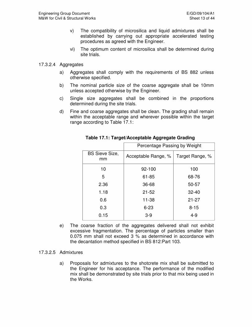
Engineering Group Document E/GD/09/104/A1
M&W for Civil & Structural Works Sheet 13 of 44
v) The compatibility of microsilica and liquid admixtures shall be established by carrying out appropriate accelerated testing procedures as agreed with the Engineer.
vi) The optimum content of microsilica shall be determined during site trials.
17.3.2.4 Aggregates
a) Aggregates shall comply with the requirements of BS 882 unless otherwise specified.
b) The nominal particle size of the coarse aggregate shall be 10mm unless accepted otherwise by the Engineer.
c) Single size aggregates shall be combined in the proportions determined during the site trials.
d) Fine and coarse aggregates shall be clean. The grading shall remain within the acceptable range and wherever possible within the target range according to Table 17.1:
Table 17.1: Target/Acceptable Aggregate Grading
Percentage Passing by Weight
BS Sieve Size, mm
Acceptable Range, % Target Range, %
10
5
2.36
1.18
0.6
0.3
0.15
92-100
61-85
36-68
21-52
11-38
6-23
3-9
100
68-76
50-57
32-40
21-27
8-15
4-9
e) The coarse fraction of the aggregates delivered shall not exhibit excessive fragmentation. The percentage of particles smaller than 0.075 mm shall not exceed 3 % as determined in accordance with the decantation method specified in BS 812:Part 103.
17.3.2.5 Admixtures
a) Proposals for admixtures to the shotcrete mix shall be submitted to the Engineer for his acceptance. The performance of the modified mix shall be demonstrated by site trials prior to that mix being used in the Works.
Engineering Group Document E/GD/09/104/A1
M&W for Civil & Structural Works Sheet 14 of 44
b) Compatibility of all admixtures with each other and with all other shotcrete constituents shall be verified during site trials.
c) Admixtures shall be free of chlorides. In any case the percentage of chlorides shall never exceed 0.1% by weight.
17.3.2.6 Accelerators
a) Only the minimum quantity of accelerator necessary shall be permitted in normal shotcreting operations. This quantity shall be determined by trials. However, 6% by weight of cementitious material shall be the maximum allowable dosage of accelerator.
b) Testing of accelerators with regard to strength decrease of the shotcrete at 28 days shall be determined by trials.
c) At the dosage chosen for use in the Works, the decrease in strength at an age of 28 days, shall not exceed the following when compared to an unaccelerated mix:
− accelerators in powder form : maximum 45%
− accelerators in liquid form : maximum 30%
d) The accelerators delivered to the site shall be tested in accordance with this Specification not less than once every two months for their reaction with the cement used (strength decrease). In the case of accelerators in liquid form, their stability during storage shall be visually inspected and checked for crystallisation at the same intervals. Storage times and working temperature ranges shall be in accordance with the manufacturer’s recommendations. The manufacturer’s safety instructions shall be observed.
e) Sodium silicate (waterglass) shall not be used.
f) The testing of setting time for selected types of accelerator shall be carried out in accordance with the supplier’s recommendations and test procedure set out below.
i) The temperature of the cement and water shall be as
recommended by the supplier but shall not be more than 30°C.
ii) 1200g of cement shall be placed in the mixing bowl of a Hobart 5 litre mortar mixer or similar.
iii) When testing powder accelerators, the powder shall be weighed and then added to the cement in the mixing bowl and mixed on speed No.1 for 2 minutes to ensure even distribution. Liquid accelerators shall be added to the mixing water.
iv) 420ml of water shall be added to the mixture in the bowl within approximately 2 sec with the mixer on speed No 1. After 5 sec the mixing speed shall be changed to No 2 for a further 15 sec.
v) The cement paste shall be taken from the mixing bowl by means of a spatula and placed in a Vicat mould (BS 4550:Part 3: Section 3.6) and lightly tamped to ensure no entrapped air is present in the sample. The top surface shall be struck off level and the mould placed on the Vicat apparatus within 20 sec of completion of mixing (i.e. 40 sec from addition of water).
Engineering Group Document E/GD/09/104/A1
M&W for Civil & Structural Works Sheet 15 of 44
vi) The determination of initial set shall be in accordance with BS 4550:Part 3: Section 3.6 and final set shall be determined by continuing the use of the initial set method and recording the time at which the needle penetrates the top surface by less than 1mm. Times shall be measured from the moment of water addition.
vii) If the initial setting is less than 40 sec or more than 80 sec or the final setting more than 150 sec, the test shall be repeated using a smaller or higher dosage of the accelerator.
17.3.2.7 Plasticisers and Retarders
a) Plasticisers and retarders may be used to reduce the quantity of the mixing water and to improve the pumpability of the shotcrete. The effects of the plasticiser shall be determined by site trials.
b) Plasticisers and Retarders shall comply to BS 5075: Part 1.
c) Shotcrete made with plasticisers and retarders shall be checked regularly for the setting time, water reduction and the development of strength as compared to the unmodified base concrete.
17.3.2.8 Metering of Admixtures
Admixtures shall be added to the shotcrete mix mechanically, which shall incorporate a metering device to accurately control the dosages. The metering device shall be built such that unauthorised alteration of the agreed dosage is prevented.
17.3.2.9 Fibres
Following types of fibres may be used subject to the acceptance of the Engineer:
a) Steel Fibres
Steel fibres for shotcrete reinforcement shall be deformed type, conform to the requirements of ASTM A820-90 and shall have an aspect ration in the range of 30 to 150 and lengths in the range of 12 to 64mm.
b) Synthetic Fibres
Synthetic fibres for shotcrete reinforcement shall be in accordance with an acceptable standard or regulation.
17.3.3 Shotcrete Requirements
17.3.3.1 General
Shotcrete shall be capable of being applied in layers of up to 150- 200mm in thickness with good adhesion to the excavated face or previous layers of shotcrete. The applied shotcrete shall, without sagging, ensure good encasement of reinforcement, steel arches and inserts.
Engineering Group Document E/GD/09/104/A1
M&W for Civil & Structural Works Sheet 16 of 44
17.3.3.2 Strength
Strength tests shall be carried out on cored samples, 100mm in diameter and 100mm long. For the site trials, the samples shall be taken from cores drilled into test panels in the direction of spraying and perpendicular to the direction of spraying. For the works tests the samples shall be taken from cores drilled in the direction of spraying from shotcrete placed in the Works.
The characteristic strength shall be no less than:
a) Site Trials Grade C25 Grade C30
After 12 hours 6N/mm² 6N/mm²
After 24 hours 12N/mm² 12N/mm²
After 3 days 18N/mm² 23N/mm²
After 7 days 23N/mm² 28N/mm²
b) Testing the Works Grade C25 Grade C30
After 12 hours 5N/mm² 5N/mm²
After 24 hours 10N/mm² 10N/mm²
After 3 days 15N/mm² 20N/mm²
After 7 days 20N/mm² 25N/mm²
After 28 days 25N/mm² 30N/mm²
17.3.3.3 Visual Inspection
Shotcrete shall be dense and homogeneous without segregation of aggregates or other visible imperfections.
17.3.3.4 Shotcrete Surface
Shotcrete shall be left as sprayed until it has set. The surface shall not be worked by float or any other means. If a smooth surface is required, the Contractor shall add a finishing coat of shotcrete or apply a floated off mortar layer after the shotcrete has set.
17.3.4 Site Trials
17.3.4.1 General
a) Site trials shall be started at least three months before the shotcreting is programmed, to ensure that the required shotcrete mix is developed and all trials and testing completed satisfactorily before shotcreting commences in the Works.
b) Before starting the trials the Contractor shall propose to the Engineer for acceptance a methodology for the development of the shotcrete mix and the tests and trials to be carried out.

Engineering Group Document E/GD/09/104/A1
M&W for Civil & Structural Works Sheet 17 of 44
c) The site trials shall employ the equipment which will be used in the Works and constituent materials shall be fully representative of those to be used in the Works.
d) Test results shall be presented in a format acceptable to the Engineer.
17.3.4.2 Development of Mix Design
The design of the shotcrete mix shall be developed in four stages.
i) Development of a suitable shotcrete mix without admixtures. Trials may be based on laboratory tests.
ii) Development of a suitable shotcrete mix with admixtures. Trials may be based on laboratory tests.
iii) Spraying test panels using the shotcrete mix (including admixtures) selected to be used in the works.
iv) Spraying test panels using the shotcrete mix (including admixtures) selected to be used in the works but using accelerator content 6% by weight of cementitious material.
17.3.4.3 Procedure
a) Sampling and testing procedures shall be in accordance with BS 1881. Shotcreting equipment, including all pipelines and hoses, shall be primed with cement grout prior to mixing the first batch.
b) Testing for compressive strength shall be in accordance with BS 1881:Part 120. For other laboratory tests, relevant BS or ASTM standards shall be used.
c) During the first two stages of mix development, the laboratory tests shall include as a minimum but not be limited to testing of compressive strength, bulk density and porosity.
d) For the spraying trials an experienced nozzleman shall prepare a sufficient number of test panels. The tests shall be arranged in a manner to simulate shotcrete application to both the tunnel side wall (vertical wall) and to the tunnel crown (overhead, at least 45 degrees hanging).
e) Each panel shall be at least 600mm x 600mm in size and shall be 200mm thick. The panels shall be prepared by shotcreting into rigid plywood boxes, which shall be adequately braced and formed from 20mm thick plywood. The sides of the moulds shall be splayed out at
least at 45° to allow egress of rebound during shotcreting. The shotcrete in the panels shall adhere well to the backform, be properly compacted and exhibit no sagging. The time at which each shotcrete panel is completed shall be recorded. The panels shall be stored without disturbance, covered by polythene sheet and shall not be exposed to direct sunlight until the time of coring.
f) Cylindrical test specimens shall be cored from each test panel and tested as listed below. Drilling and dimensions of test specimens shall be in accordance with BS 1881: Part 120. Drilling of cores shall
Engineering Group Document E/GD/09/104/A1
M&W for Civil & Structural Works Sheet 18 of 44
be located to avoid areas of possible rebound. Cores to be tested at different ages may come from the same panel. For each test at least one spare specimen shall be provided. The date and time at which each test is performed shall be recorded.
i) Compressive strength in the spray direction shall be measured after 12 hours, 24 hours and 28 days on at least 4 cores each. The test cores shall be 100mm diameter and 100 mm long.
ii) Compressive strength perpendicular to spray direction shall be measured after 24 hours and 28 days on at least 4 cores each. The test cores shall be 100mm diameter and 100mm long.
g) The cores for 3 days, 7 days and 28 days compressive strength tests shall be obtained from the panels on the same day. Each cored cylinder shall be marked with a reference mark and the date and time of shotcreting and coring. The cores for 28 days strength tests shall be stored in water in accordance with BS 1881:Part 111.
h) The strength of shotcrete cores from test panels shall be acceptable if both the compressive strength results for samples with their axes parallel to the direction of spraying and the compressive strength results for samples with their axes perpendicular to the direction of spraying, comply with the requirements of Clause 17.3.3.2a.
i) The site trials shall be repeated if the source or quality of any of the materials is changed or if the mix proportions are changed.
j) Target workability values shall be determined.
k) Control values for porosity and minimum density shall be established based on the core samples.
17.3.5 Production and Transport
17.3.5.1 Batching and Mixing
a) The individual components for the production of shotcrete shall be measured by weight with an automatic batching device, except that liquid admixtures may be measured by volume. The batching accuracy shall be within ±3% for cement, water and aggregates and within ±5% for admixtures. The accuracy of the batching equipment used shall be checked at least once a month.
b) Mixing shall be carried out in a mixer suitable for the efficient mixing and discharge of dry or wet batched materials as appropriate.
c) Regular checks shall be made to ensure that complete mixing is consistently achieved.
d) Shotcrete shall be applied within three hours of mixing. Retarders may be used, with the acceptance of the Engineer, to extend the time for placing.
Engineering Group Document E/GD/09/104/A1
M&W for Civil & Structural Works Sheet 19 of 44
17.3.5.2 Transport
Shotcrete without accelerator shall be transported by any suitable means which provides complete mixing during transportation such that segregation of the mix components is prevented. The mixture shall be effectively protected against any influence of the weather.
17.3.6 Equipment
17.3.6.1 General
a) All transport pipes that carry shotcrete ingredients shall be of uniform diameter laid straight or in gentle curves and protected so that the flow of ingredients through them is not restricted.
b) The shotcrete machine shall be adjusted to suit the length of the pipe that carries the shotcrete mix. Equipment shall be leak-proof. Residual deposits of materials shall be removed after each usage.
c) The air and water supply system shall be capable of supplying the delivery machine and hose at the pressures and volumes recommended by the manufacturer of the machine. No air supply system shall be used that delivers air contaminated by oil.
d) Shotcreting equipment shall be capable of feeding materials at a regular rate and ejecting shotcrete from the nozzle at velocities that will allow adherence of the materials to the surface being shotcreted with a minimum of rebound and maximum adhesion and density.
e) The placing equipment shall be so arranged that the nozzleman may use air and water in any combination to prepare raw surfaces or to clean completed work.
f) Equipment shall be provided to allow application of shotcrete to all surfaces with the nozzle at the distances from the work specified in Clause 17.3.7.1d.
g) A boom mounted or similar device shall be provided for the spray nozzle for use in conditions where manual spraying is unsafe or otherwise unsuitable or undesirable.
h) The equipment shall be set up according to the recommendations of the manufacturer.
i) Pumping shall ensure a continuous conveyance of shotcrete including any admixture except accelerator. The equipment shall incorporate a suitable metering device for liquid admixtures.
17.3.7 Application
17.3.7.1 General
a) Before the application of shotcrete, the excavated surfaces shall be cleaned with compressed air and, as far as the local conditions permit, with an air-water mixture as necessary to remove all material which may prevent proper adhesion of the shotcrete to the ground

Engineering Group Document E/GD/09/104/A1
M&W for Civil & Structural Works Sheet 20 of 44
surface. The surface to receive shotcrete shall be damp and but without free water prior to application of shotcrete.
b) Action shall be taken as necessary to control ground water and prevent it adversely affecting the shotcrete lining. Water inflows which might cause deterioration of the shotcrete, or prevent adherence, shall be diverted by channels, chases, pipes or other appropriate means to the invert.
c) Where necessary, pressure relief holes shall be provided through the temporary lining to ensure that no hydrostatic pressure develops behind the lining. Water entering from the pressure relief holes shall be controlled and directed away from the excavated face.
d) Shotcrete shall only be applied by nozzlemen certified in accordance with Clause 17.3.7.3. The distance between the nozzle and the surface being shotcreted shall not exceed 1.5m. The nozzle shall, as a general rule, be held closer and perpendicular to the application surface except as necessary to permit proper encasement of reinforcement and minimise rebound.
e) No rebound material is to be covered with shotcrete. To facilitate this, and depending on ground conditions and the excavation cycle, the shotcrete shall preferably be applied from the shoulder to the crown. For vertical and near vertical surfaces application shall commence at the bottom. Layer thickness shall be governed mainly by the requirement that the material shall not sag. The rebound material shall be removed from the tunnel and shall not be used in the Works.
f) Each layer of shotcrete shall be built up by making several passes of the nozzle over the working area. The shotcrete shall emerge from the nozzle in a steady uninterrupted flow. Should the flow become intermittent for any cause the nozzleman shall direct it away from the work until it again becomes constant.
g) Where a layer of shotcrete is to be covered by succeeding layers, it shall first be allowed to set and loose material and rebound shall be removed. The surface shall be finally cleaned and wetted using a blast of air and water.
h) All joints shall be carefully cleaned of all rebound and loose material using a combination of air and water. Particular attention shall be given to cleanliness and preparation of all invert joints.
i) Where two layers of reinforcement are used, the far layer shall be covered by shotcrete before the near layer is installed. The near layer shall be covered by shotcrete up to the required thickness with the minimum of delay.
17.3.7.2 Shotcrete Thickness and Cover
The minimum thickness of shotcrete shall be in accordance with the Drawings.
To provide a means of determining the thickness of shotcrete applied, appropriate thickness markers, acceptable to the Engineer, shall be used.

Engineering Group Document E/GD/09/104/A1
M&W for Civil & Structural Works Sheet 21 of 44
Steel arches, wire mesh and other reinforcement shall have at least 30mm of shotcrete cover unless otherwise accepted by the Engineer.
17.3.7.3 Proficiency of Operatives
Shotcrete shall be applied only by nozzle operators, who have successfully demonstrated their competence and their ability to produce shotcrete complying in all respects with this Specification and shall hold certificates of competence issued by the Contractor and accepted by the Engineer.
17.3.8 Testing of the Works
17.3.8.1 General
a) During the execution of SCL works, both strength tests and stiffness tests shall be carried out on shotcrete core samples based on procedures described below.
b) Test results shall be presented in a format acceptable to the Engineer.
c) Based on the results of the stiffness and strength tests, the designer of the particular SCL structure shall assess the actual stability of the SCL structure compared to the design assumptions.
d) If the stability of the SCL tunnel is endangered because shotcrete does not meet the specified requirements considered in the SCL design, the affected shotcrete shall be repaired or replaced carefully or where practicable the deficiencies made good by application of additional shotcrete layers. Applied methods and working sequences shall be identified on a CRESS and shall be acceptable to the Engineer.
17.3.8.2 Strength Tests
a) Compressive strength tests shall be carried out on cores taken from shotcrete in the Works in accordance with BS 1881: Part 120. The locations where the samples shall be taken (chainage and side wall, crown or invert) shall be agreed with the Engineer. The Contractor’s attention is drawn to the fact that the Engineer will require samples taken from the crown and the invert.
b) The time of coring shall be as close as possible to 12 and 24 hours after placing. Cores required for 3, 7 and 28 day strength tests shall be obtained at the same time as those for 1 day tests and stored in the laboratory in accordance with BS 1881:Part 111.
c) The frequency of coring shall be such as to obtain 3 cores each for 12, 24 hours and 3, 7 and 28 day tests for at least every 5 linear metres of tunnel. Depending on the compliance of test results with this Specification, circumstances of application and importance of construction, the frequency of work tests may be reduced or increased, subject to the agreement of the Engineer. The cores shall be drilled through the whole thickness of the shotcrete and visually
Engineering Group Document E/GD/09/104/A1
M&W for Civil & Structural Works Sheet 22 of 44
inspected to verify that the shotcrete is dense and homogeneous without segregation of aggregate or other visible imperfections.
d) Tests for 12 and 24 hours strength shall be carried out at 12 hours ± 1 hour and 24 hours ±2 hours respectively.
e) The Contractor may propose indirect testing methods such as penetration and pull out test methods to determine the 12 hours and 24 hours strength of shotcrete, instead of testing cores taken from shotcrete placed in the Works. In this case, proposed testing methods shall be submitted to the Engineer for acceptance. If indirect methods are to be used, additional test panels shall be prepared underground to calibrate the indirect method to the direct method. Mechanical rebound hammers shall not be used to obtain indirect compressive strength of shotcrete.
f) Where the nominal shotcrete thickness is considered too small to achieve a core of sufficient length, the cores samples shall be taken from designated areas, where the actual shotcrete thickness has been locally increased for subsequent test coring as directed by the Engineer.
g) Any test result shall not be lower than the specified characteristic strength by more than:
i) 1.0 N/mm2 for 12 hour strength
ii) 2.0 N/mm2 for 24 hour, 3 days and 7 days strength
iii) 3.0 N/mm2 for 28 day strength
h) If the shotcrete fails to meet the Specification, the validity of the test results shall be assessed prior to implementing remedial action acceptable to the Engineer.
17.3.8.3 Stiffness Tests
a) These tests shall be carried out to assess the stiffness behaviour of shotcrete in the Works under site conditions. The tests shall produce the modulus of elasticity of shotcrete samples and shall be carried out in accordance with the test procedure described in clauses below.
b) Within the first 50m of SCL works at least 2 sets of stiffness tests shall be carried out. One set of stiffness tests consists of a series of test carried out after 1, 3, 7 and 28 days, carried out on 3 cores. The locations where the samples shall be taken from (chainage and side wall, crown or invert) shall be agreed with the Engineer. The Contractor’s attention is drawn to the fact that the Engineer may require samples also taken from the crown and the invert.
c) The tests shall be carried out on cores taken from shotcrete produced in the Works in accordance with BS 1881:Part 120. The cores shall be 100 mm in diameter and 200 mm long. Where the nominal shotcrete thickness is considered too small to achieve a core of sufficient length, the cores samples may be taken from designated areas, where the actual shotcrete thickness has been locally

Engineering Group Document E/GD/09/104/A1
M&W for Civil & Structural Works Sheet 23 of 44
increased for subsequent test coring as directed by the Engineer. Alternatively, the contractor may propose to take the samples from test panels produced in the Works under site conditions at the point of current shotcrete application underground. The panels shall be stored underground in the Works (with the same climatic conditions as the shotcrete placed in situ). Core samples shall be taken from the panels just before testing, and shall be tested on the same day.
d) The modulus of elasticity shall be determined in a non-destructive manner as described below on the same core sample after 1, 3, 7, 28 days on 3 cores. After the 28 days test, the samples shall be tested for its compressive strengths.
e) The test procedure shall be as follows:
i) Axial strain shall be measured on the central part of the sample.
ii) The modulus of elasticity at different shotcrete ages shall be determined by three loading-unloading cycles. The upper load test limit shall be ⅓ and the lower test limit shall be 1/30 of the respective compressive strength.
iii) The modulus of elasticity is defined as the ratio stress-difference over strain-difference relative to the upper and lower test load limit.
17.3.8.4 Workability Tests
a) The workability of shotcrete shall be measured by slump tests in accordance with BS 1881 after the addition of plasticiser. Samples shall be tested for every mix produced.
b) The workability shall be within ±25mm or ±⅓ of the target value, whichever is the greater, determined during the site trials.
17.3.8.5 Thickness Tests
(a) The thickness of placed shotcrete shall be checked by drilling small holes to determine the ground/shotcrete interface. These tests shall be performed at least every 200m² of applied shotcrete. The number and positions of measurement locations shall be as agreed with the Engineer.
(b) At each measurement location 4 holes shall be drilled, one in each corner of a 1 metre square. At least 3 holes shall show a shotcrete thickness equal to or greater than the required minimum thickness shown on the Drawings. It will not be acceptable for any of the four holes to show less than 85% of the required minimum thickness shown on the Drawings.
17.3.8.6 Test Procedure for Bleeding of Cement
If there is no other procedure recommended by the cement supplier and acceptable to the Engineer, the following test procedure shall be adopted to determine the bleeding characteristics of the cement:
Engineering Group Document E/GD/09/104/A1
M&W for Civil & Structural Works Sheet 24 of 44
i) Pour exactly 98g of water with a temperature of 25°C into a 250ml glass beaker with a small magnetic stirring rod. At medium stirring rate add 115g of cement at a constant rate in 20 seconds. Combine the mixture for 2 minutes until a homogeneous, thin cement paste of water/cement ratio of 0.85 has been achieved.
ii) Fill the homogenized mass into a 100ml measuring cylinder up to the 100ml index mark by means of a glass rod (do not pour directly into cylinder). The measuring cylinder shall be kept in a high glass
beaker filled with water at 25°C during the entire period of testing.
Fluctuations in temperature shall not exceed ±2°C.
iii) After 120 minutes the amount of cement which has settled shall be read from the scale, and the amount of supernatant water shall be determined. The reading shall be in a unit corresponding to % by volume of repelled water.
17.3.8.7 Strength Decrease
The decrease in strength due to addition of accelerator shall be determined according to the following procedure: i) Mortar cubes shall be used in accordance with EN196.
ii) A comparison of the 7 day and 28 day strengths of mortar shall be carried out as follows:
iii) Strength (A) shall be determined without the accelerator
iv) Strength (B) shall be determined with the accelerator with dosage used for the setting time tests
v) Strength decrease is (A – B) x 100 % A
17.3.9 Health and Safety
17.3.9.1 General
The requirements of M&W Specifications Chapter 16 shall apply.
17.3.9.2 Access
a) To apply shotcrete in accordance with the requirements of Clause 17.3.7, it may be necessary for the nozzleman to stand at an elevated position. For this purpose the contractor shall use a basket, working platform, scaffolding or similar, to the acceptance of the responsible safety officer.
b) Access to the area of shotcrete application shall be restricted while equipment is operating. All personnel, other than the nozzle operator, shall work at a safe distance from the spraying operations in a safe working environment.

Engineering Group Document E/GD/09/104/A1
M&W for Civil & Structural Works Sheet 25 of 44
17.3.9.3 Dust Level and Ventilation
Silica levels in dust produced by the shotcrete process shall be monitored. The Occupational Exposure Level limit value shall be less than 5mg/m
3,
and is expressed as:
OEL = 10 mg/m3
S + 2
Where S is the percentage of respirable crystalline silica.
Adequate ventilation for the shotcrete operators shall be provided by the Contractor and shall be acceptable to the Engineer.
17.3.9.4 Care of Substances Hazardous to Health (COSHH) Regulations
All components of shotcrete which are potentially hazardous shall be marked, stored and used in accordance with Care of Substances Hazardous to Health regulations.
17.3.9.5 Personal Protective Equipment
Operators shall have full protective sealable clothing and use respirators, ear defenders and eye protection as required. Any skin likely to be exposed during the work shall be protected with a barrier cream.
17.3.9.6 Illumination
Adequate illumination shall be provided in the area where shotcrete is placed. A minimum lighting intensity shall be agreed with the Engineer.
17.3.9.7 Communications
Good communications between nozzle operator and pump operator shall be maintained at all times during the shotcrete process. The Contractor shall provide details in his Method Statement of how communications are established.
17.3.9.8 Overhead Shotcrete
Freshly applied overhead shotcrete should be considered as a safety hazard. Until the shotcrete hardens the potential of breakouts of shotcrete placed in the roof of the tunnel exists. Therefore access to the shotcreted area for unauthorised personnel shall be prevented by controlling entry to this area of the tunnel.

Engineering Group Document E/GD/09/104/A1
M&W for Civil & Structural Works Sheet 26 of 44
17.4 OTHER TEMPORARY SUPPORT
17.4.1 Rock bolts
17.4.1.1 Types
a) Ordinary Rock Bolt This type of rock bolt is an untensioned rod inserted into a drilled
hole and grouted along its entire length using cement grout. The rock bolt consists of a high yield steel deformed ribbed bar with cut or rolled threads at one end, a faceplate, shim plates and a nut.
b) Pre-stressed Rock Bolt
This type of rock bolt is a tensioned rod inserted into a drilled hole and grouted at the far end over a defined anchor length by quick setting resin grout or similar. The rock bolt consists of a high yield steel deformed ribbed bar with cut or rolled threads at one end, a faceplate, shim plates and a nut. After the resin grout has gained sufficient strength, the nut is tightened to achieve a defined pre-stressing force in the rod. The rod shall be grouted along its entire remaining length using cement grout before the permanent lining is placed.
c) Injected Bored Rock Bolt (IBO Rock Bolt or similar)
The IBO rock bolt is used in situations where it is difficult to keep the drill hole open sufficiently long to install a regular fully grouted rock bolt. The IBO rock bolt consists of a perforated steel tube, which is left in place as a sacrificial drilling rod and which is subsequently grouted. The rod is a thick-walled tube with an internal diameter of 15mm and a rolled thread along the full length of the extrados to facilitate flushing of drilled material and bond to the grout. The drill bit diameter shall be between 52 and 75mm. If the IBO rock bolt has to be extended, the extension coupler shall be not less than 2m from the shotcrete face. Between 12-24 hours after grouting, the bolt shall be tensioned with a load of typically 50kN.
d) Swellex Type Rock Bolt
This type of rock bolt is manufactured from a mechanically reshaped steel tube. Bushings are pressed onto the ends, which are sealed through welding. The lower bushing has a flange to hold a faceplate in place. High pressure water (300 bars) is injected into the steel tube through a hole in the lower bushing. This causes the steel tube to expand and to deform it against the irregularities in the drilled hole. A 200mm long sleeve tube made of steel prevents the rock bolt from swelling at the borehole collar. The drillhole diameter has to be adjusted to suit the size of the rock bolt.
e) Fibreglass Rock Bolt: Cement grouted
This type of rock bolt is an untensioned rod made from fibreglass
bonded together by resin. One end of the rod is cut at 45° angle to provide a bevelled end and the other end is threaded to receive a nut. A fibreglass face plate and a fibre/resin nut of proprietary
Engineering Group Document E/GD/09/104/A1
M&W for Civil & Structural Works Sheet 27 of 44
manufacture completes the assembly. The surface of the bonded fibres is left to provide a rough surface to improve bond with grout. Fibreglass rock bolts are usually used to strengthen excavated faces where subsequent tunnelling work is to be carried out or to provide temporary support to an excavation face during stoppages. Fibreglass rock bolts may be recovered and reused if circumstances permit, subject to the agreement of the Engineer. Steel faceplates and steel nuts may be used with fibreglass rock bolts but these shall be removed before excavation is resumed.
17.4.1.2 Materials
a) Cement shall be Ordinary Portland or Rapid Hardening Portland cement comply with BS 12, BS 1370 or BS 4027, and comply with the requirements of Chapter 11 Concrete and Reinforcement.
b) Cement grout shall have a water cement ratio of 0.3 to 0.35 and shall achieve a characteristic strength of at least 10N/mm
2 at 2 days and
30 N/mm2 at 28 days when tested on mortar cubes in accordance
with BS 4550. Rock bolts grouted with cement grout shall be capable of sustaining a pullout force of 60% of the working load 12 hours after grouting. This shall be determined by site trials prior to work commencing.
c) Other admixtures including plasticisers or expanding agents shall conform to BS 5075 and shall be used only with the Engineer’s agreement. The admixtures used shall have no detrimental effect on the performance of the rock bolts. Admixtures containing chlorides shall not be used.
d) Resin based grouts shall be tested in accordance with BS 6319. Full details of the resin based grout, intended to be used, shall be agreed with the Engineer.
e) Faceplates shall be of dished shape in steel to BS 4360 Grade 43A and shall have hemispherical seating and a centralised slot to suit the dimensions of the different rock bolts. The dimensions of the faceplates shall be typically 150mm x 150mm x 8mm thick.
f) Bolts, nuts and seatings shall comply with the requirements of BS 4190.
g) Steel bars shall be grade 460 complying with BS 4449.
h) Fibreglass rock bolts shall be made from polyester resin reinforced with glass fibres in continuous strands. The glass strands shall form 65% to 75% of the weight of the rock bolt. Faceplates made from fibreglass shall have a minimum diameter of 130mm.
i) Rock bolts shall be manufactured such that they shall be capable of withstanding a working load of not less than 100kN and the cross sectional area shall be not less than 250mm
2.
Engineering Group Document E/GD/09/104/A1
M&W for Civil & Structural Works Sheet 28 of 44
17.4.1.3 Drilling and Installation
a) The exact locations of rock bolts shall be adapted to suit the prevailing geological conditions. When necessary to ensure the safety of the Works, rock bolts shall be installed immediately behind the face. The detailed procedures to be adopted for the installation of the rock bolts shall be in accordance with the agreed Method Statement.
b) Holes shall be drilled with an accuracy of ±10° with regard to the direction defined.
c) Drillhole diameter shall be within the range recommended by the rock bolt manufacturers to match the particular rock bolt diameter and any couplers required for extending the rock bolts.
d) Holes shall be drilled using sharp bits to produce straight holes of the required length. On completion of each drillhole and prior to the installation of each rock bolt, drillholes shall be cleaned to remove debris.
e) Installation shall be made in accordance with the rock bolt manufacturer’s recommendations and generally as follows:
i) Some preparation of the shotcrete surface at the drillhole or rock bolt location may be necessary, involving trimming local surface irregularities or forming pads of quick setting mortar. Where mortar pads are required, they shall be larger than the
faceplates and the edges shall be chamfered at 45°. Care shall be taken to ensure the mortar does not interfere with the installed rock bolt. Faceplates shall be tightly screwed against the surface using hand wrenches.
ii) The grouting material shall be injected starting from the furthest end of the drilled hole such that the rock bolt rod is completely encased in grout. The open ends of holes shall be sealed to prevent grout loss. Any grout on the exposed threads of the rock bolts shall be cleaned off.
iii) Rock bolts installed in overhead positions shall be supported where necessary until the grout has set.
17.4.1.4 Testing of Materials
a) Sets of six cubes of cement grout shall be taken for every 50 bolts installed. Sampling, preparation, curing and testing shall be in accordance with EN196.
The strength determined from any single test result shall be not less than the specified characteristic strength by more than:
1 N/mm2 for cement grout tested after 1 day
3 N/mm2 for cement grout tested after 28 days
b) Tensile tests shall be carried out on proportions of steel rock bolt bars containing the threaded length from each batch of bars generally in accordance with BS 4449 and BS 18. At least three bars
Engineering Group Document E/GD/09/104/A1
M&W for Civil & Structural Works Sheet 29 of 44
in every 1000 shall be tested to destruction. Tests may be carried out at the manufacturer’s works or on Site. Test certificates shall be provided.
c) At least one in every 100 fibreglass rock bolts with a minimum of 3 from every batch delivered to Site shall be tested to destruction. Batches of fibreglass rods, which fail at loads less than 1.5 times the working load shall be rejected.
17.4.1.5 Trials and Testing of Rock Bolts
a) Prior to commencement of installation of rock bolts, 5 trial rock bolts of each type to be used in the Works shall be installed and tested. Two of the trial rock bolts shall be tested at 60% of the working load after 12 hours and the remaining tested at working load between 3 and 21 days after installation. Trial rock bolts shall be installed in similar ground conditions to those which are likely to be encountered during installation in the Works and shall be in accordance with the Specification.
b) 2% of the rock bolts installed in the Works shall be load tested to 60% of the working load, 12 hours after grouting. 5% of the installed rock bolts shall be tested to working load between 3 and 21 days after installation. Rock bolts, which fail the tests, shall be replaced.
c) The in-situ tests shall be carried out in accordance with the method for determining the strength of a rock bolt anchor given in Rock Characterisation Testing and Monitoring: ISRM Suggested Methods edited by E.T. Brown (Pergamon Press 1981). The specified test loads shall be applied and then released at the end of the tests.
d) The in-situ load tests shall be carried out to a working load of 90 kN and this load sustained for at least 10 minutes.
17.4.1.6 Records
Records shall be kept for each rock bolt installed and copies of all records shall be maintained on site after installation of the rock bolt or completion of testing, as appropriate.
17.4.2 Forepoling
17.4.2.1 General
a) Forepoling is a general term for the insertion of ground supports outside and ahead of the excavated tunnel face by the installation of linear type ground reinforcement at intervals around the crown,
usually at an angle of 10° to 15° with the tunnel direction. Treatment may include the following:
− Ungrouted spiles
− Grouted spiles inserted into a drilled hole and grouted along their entire length using cement grout.

Engineering Group Document E/GD/09/104/A1
M&W for Civil & Structural Works Sheet 30 of 44
− Injected steel pipes driven into the ground or inserted into a borehole and grouted by injection.
− Interlocking steel sheets driven to form an arch ahead of the tunnel face.
17.4.2.2 Materials
a) Spiles shall consist of high yield steel deformed bars or steel tubes in accordance with BS 4449 or BS 4461 and of diameter not less than 25mm.
b) Injected steel pipes may be utilised for forepoling and shall consist of weldable steel pipes with an internal diameter of at least 32mm and a minimum wall thickness of 4.5mm, with a thread cut at one end and a strong pointed steel tip at the other end. Perforations with a diameter of typically 8 mm at 200mm longitudinal spacing are provided along two thirds of the total length of the pipe starting from the tip. If necessary, the injected steel pipes are provided with face plates which are tightly screwed at the face of the shotcrete.
c) Where interlocking steel sheets are required for forepoling, they shall be grade 43 steel to BS 4360.
d) Grout used for grouting spiles or injected steel pipes shall be in accordance with Clause 17.4.1.2.b and Clause 17.4.1.4 a.
17.4.2.3 Application
a) Forepoling shall be used wherever ground conditions require support to allow excavation to proceed in a safe environment.
b) Forepoling shall be used in conjunction with lattice girders or steel arches. The forepoling shall be driven above the arch or through the lattice girder closest to the excavation face.
c) The length and type of forepoling shall be selected to suit the ground conditions and the expected length of advance. Typically, the length of forepoling shall be at least twice the excavation advance.
d) Typical spacing of the forepoling spiles is between 250 and 500 mm around the crown and that of injected steel pipes between 500 and 1000mm. The actual spacing used shall be selected to suit the ground conditions, and shall be to the satisfaction of the Engineer.
e) Injected grout shall have achieved initial set before advancing the excavation.
17.4.3 Support Arches
17.4.3.1 General
a) Support arches may be installed to maintain the designed shape of the excavation and to provide an immediate support at the working face and over the length of the previous excavation step.
Engineering Group Document E/GD/09/104/A1
M&W for Civil & Structural Works Sheet 31 of 44
Where support arches are not used the Contractor must propose other measures to ensure that the designed shape of the excavation is maintained and to provide adequate support at the working face and over the length of the previous excavation step.
b) Support arches may be formed by a rolled steel sections or by lattice
girders. The size (depth) of the steel arch shall be chosen to fit to a particular shotcrete thickness and profile.
c) Lattice girders shall have three circumferential bars with two bars positioned on the back face of the shotcrete lining.
17.4.3.2 Materials
a) Material for steel sections shall be in accordance with BS 4449 or BS 4461. All steel shall have a minimum characteristic strength of
460N/mm2 and shall be of ‘weldable classification’.
b) Material for lattice girders shall comply with BS 4449, BS 4360 with a minimum characteristic strength of 460 N/mm
2 or to DIN 488 (Class
B St 500S).
c) Fabrication of materials supplied in accordance with DIN 488 shall comply with:
Welding - DIN 4100
Weld Testing - DIN 267
Connections - DIN 18200
d) Test certificates shall be obtained from the supplier confirming compliance with the appropriate Standards.
e) At the time when the steel arches are encased in shotcrete, they shall be free from rust, oil, paint, concrete retarders, loose rust, loose mill scale, grease or any other substances, which could adversely chemically affect the steel or concrete or reduce the bond.
17.4.3.3 Fabrication and Erection
Fully detailed fabrication drawings and specifications for all components of the steel arches shall be prepared before commencement of manufacture. Manufacture shall be in accordance with these drawings and specifications.
17.4.3.4 Welding
All welding shall be carried out in accordance with BS 5135 or DIN 4100.
17.4.3.5 Connections
a) All connections shall be rigid and capable of resisting the full sectional bending moments, axial forces (tension and compression) and shear forces within a divisional excavation section. Hinged connections are acceptable if the steel arch or lattice girder is installed around the full circumference of the cross section.
Engineering Group Document E/GD/09/104/A1
M&W for Civil & Structural Works Sheet 32 of 44
b) Bolts for bolted connections shall be black bolt in accordance with BS 4190.
c) The connections shall be designed to allow complete cover with shotcrete, so that no voids are created behind the connections.
17.4.3.6 Tolerances
a) Arches shall not deviate from the design shape by more than ±25mm.
b) The length of a complete arch shall not deviate from the design length by more than ±25mm.
c) The erected arches shall not depart from their design position by more than 50mm.
d) The arches shall be erected within ±100mm of the design centres as detailed in the agreed Method Statement.
17.4.4 Reinforcement
17.4.4.1 General
The reinforcement mesh shall be cleaned of any previously deposited material, which might prevent a proper bond. The standard mesh grid shall be 100mm x 100mm made up of 6 to 8mm diameter steel bars. If only one layer of mesh is applied, this shall be installed at the intrados of the initial shotcrete lining.
If not specified otherwise on the design drawings the overlap of wire mesh shall be two pitches.
17.4.4.2 Fixing
Reinforcement mesh shall be securely fixed in place. Ties, anchors and supports for the mesh shall be made of steel and suitable spacers shall be provided where necessary. Timber packings shall not be used. The method of fixing the mesh shall be such that shotcrete can be compacted soundly behind the reinforcement at all points. Laps shall be a minimum of two pitches. Additional fixings shall be installed as necessary to fit the mesh to the excavation profile.
17.5 INSTRUMENTATION AND MONITORING 17.5.1 General
a) The requirements in this Section shall be complied with for instrumentation and monitoring for the SCL works, in addition to the Instrumentation requirements elsewhere in the Contract Documents and in Chapter 9 of this specification.
b) The Contractor shall submit to the Engineer for acceptance a detail method statement for instrumentation and monitoring, including instrumentation layout, trigger, design and allowable values and the procedures for the evaluating the monitored data.
Engineering Group Document E/GD/09/104/A1
M&W for Civil & Structural Works Sheet 33 of 44
c) During construction, the monitoring shall provide a database to verify the SCL design based on the actual ground mass behaviour. In addition, the monitoring results shall provide information to confirm the integrity of existing structures and that the installed ground support measures are sufficient to fulfil the contract requirements.
d) The Contractor shall appoint within his site team an experienced Monitoring Engineer who shall lead the Contractor’s monitoring team. The Monitoring Engineer shall attend the daily monitoring meeting with the Engineer where the results of the previous day’s monitoring shall be presented to the Engineer by the Monitoring Engineer.
e) The frequency of such review meeting shall be increased as requested by the Engineer.
f) The Contractor’s Site Manager shall attend monitoring review meetings as requested by the Engineer.
g) After hand-over to the Authority, the permanent monitoring shall provide data on the actual long-term behaviour of the underground structures for the judgement of stability and performance.
17.5.2 Deformation of the SCL
Deformations of the primary lining shall be monitored by observing movement of measuring bolts installed immediately after the excavation. Measuring bolts shall be fixed during the course of tunnel advance, before or after the application of the shotcrete within 1 m of the face. The following measurements shall be taken:
a) Optical measurements using high precision opto-electronic theodolite.
b) Tape or tape extensometer measurements, especially where optical measurements cannot be taken.
Deformation measurements shall be taken in arrays at intervals, acceptable to the Engineer, along the tunnel as well as at junctions, bifurcations and in adjacent openings. The position of the measuring bolts shall be adjusted to suit the excavation sequence adopted.
17.5.3 Stresses of the SCL
Strain gauges shall be installed in circumferential direction in order to assess the load build-up and distribution on the primary lining. The strain gauges shall be located at mid depth of the shotcrete as far as practicable.
17.5.4 Deformation of the SCL Lining
Deformations of the SCL lining shall be monitored by reading the level of the measurement bolts and by measuring changes in the distance between the bolts by an accurate measuring tape. These measurements shall be taken to assess the long-term effects at sections of special

Engineering Group Document E/GD/09/104/A1
M&W for Civil & Structural Works Sheet 34 of 44
interest, especially in the area where the ground treatment has been carried out.
17.5.5 Interpretation of Readings
a) General Immediately after the readings have been taken, the measurement
results shall be entered respectively into time-deformation and time-stress diagrams, in order to evaluate the stability behaviour of the excavation.
The diagram used shall also show:
i) The Project details
ii) The type of measurement, such as deformation, stress, convergent.
iii) The diagram page reference.
iv) The location and chainage of the measuring points.
v) A sketch of the cross section of the tunnel with clearly marked positions of the measuring points.
vi) The detail of the excavation process such as:
• Distance of measuring point from the face
• Excavation of heading, bench and invert in relation to the measurements
• Location of adjacent openings.
vii) The duration shall be recorded between the excavation and initial reading taken at the measured section.
b) Deformation Measuring
The results of the deformation measurements shall be further evaluated using an appropriate diagram to identify critical deformations likely to take place. Deformation measurements shall be supplemented by visual inspections of the surface of the tunnel walls. The development of cracks or shearing of surfaces observed shall be used to assess the rate of the deformation.
c) Extensometer Measurements
The results of extensometer readings which indicate the relative movements between measuring points shall be entered into a diagram to indicate the extent of the ground displacement around the openings due to the stress redistribution processes.
d) Strain Gauges
Circumferential stresses shall be measured in the temporary shotcrete lining and results shall be entered into a diagram. The development of circumferential stress over time, in particular, shall be monitored.
Engineering Group Document E/GD/09/104/A1
M&W for Civil & Structural Works Sheet 35 of 44
17.6 PERMANENT LINING The permanent cast in-situ linings shall be constructed in accordance with Chapter 16 Bored Tunnels and Related Works.
17.7 WATERPROOFING SYSTEM
17.7.1 General
17.7.1.1 Scope of Section
This Section covers the waterproofing for all SCL underground structures by means of a continuous waterproofing membrane installed to the outside of the secondary concrete lining. It does not include provisions for other elements such as water stops in concrete, sealing of joints etc.
17.7.1.2 Description
a) The purpose of the membrane waterproofing to underground struc-tures is to prevent leakage of groundwater into the tunnels and shafts and to protect the concrete lining against deleterious chemical influ-ences. In the tunnels, the waterproofing shall be applied to the full circumference as shown on the Drawings. The waterproofing membrane shall always be located between shotcrete support and the permanent concrete lining.
b) The waterproofing system shall consist of two layers: the first layer shall be a protective geotechnical fleece fastened to the shotcrete surface; the second layer shall be the actual waterproofing membrane properly fixed by special means as recommended by the manufacturer. While the sealing function shall be provided by the membrane, the layer of fleece is required to protect the waterproofing membrane against damage from contact with the shotcrete surface, to prevent interlocking between concrete and shotcrete in case of differential movements.
17.7.1.3 Submissions by the Contractor
The following information shall be furnished to the Engineer for acceptance in accordance with the Contract requirements:
a) Comprehensive and detailed Method Statement describing the installation of the waterproofing membrane including the equipment used for welding, testing of welding seams, and appropriate day-to-day procedures to ensure the quality of welding seams.
b) Certificates of compliance and test results/reports attesting that the materials meet specification requirements.
c) Manufacturer's instructions for installation of fleece and waterproofing membrane, including procedures for preparation, fixing, welding and splicing, flashing etc.
Engineering Group Document E/GD/09/104/A1
M&W for Civil & Structural Works Sheet 36 of 44
d) Manufacturer's and installer's qualifications to include evidence of experience of the manufacturer and the installers, as well as resume of supervisors for the waterproofing system installation.
e) Samples as listed hereafter:
i) Membrane: One square metre of each type of membrane.
ii) Fleece: One square metre of each type of fleece.
iii) Welded splice: 1 m of welded membrane splice for each type of membrane.
iv) Fixings and fittings: 10 samples from different lots of roundels and shotnails, 2 samples of sealing flanges for each type of pipes passing through the membrane.
f) Shop Drawings shall be submitted for acceptance showing all necessary installation details for fleece and waterproofing membrane, including installation sequence, position of joints, treatment of projections, connection to waterstops, local reinforcements etc.
17.7.1.4 Quality Assurance
a) Only suitable products shall be supplied and installed, which are designed and manufactured specifically for application in underground structures under conditions similar to those encountered on this Project and which show an acceptable perfor-mance.
b) A manufacturer (or manufacturers) shall be selected who is (are) regularly engaged in the production of similar materials for underground structures and has (have) demonstrated successful application on at least five recent projects of comparable nature.
c) The manufacturer's representative shall be present at least during the first 10 working days of installation and later as often as required by the Engineer.
d) Unless the Contractor can show he has the necessary previous experience in the erection of waterproofing systems of the specified type (minimum 10 years) and that he has available the experienced personnel, he shall make use of an experienced specialist subcontractor to carry out the waterproofing work. The initial choice of subcontractor as well as any change that may be required by the Contractor at a later stage shall be submitted to the Engineer for acceptance.
e) All installation and testing shall be carried out under the direct supervision of an individual with recent, continuous, experience in the installation of waterproofing systems for underground structures.
f) All personnel involved in installation and testing of the waterproofing system shall be provided with adequate training prior to the beginning of the waterproofing works.

Engineering Group Document E/GD/09/104/A1
M&W for Civil & Structural Works Sheet 37 of 44
g) Installation records shall be submitted to the Engineer for acceptance with all relevant data for all seam checks etc. These records shall form part of the submission to obtain acceptance to proceed with the installation of the concrete lining.
17.7.2 Materials
17.7.2.1 General
Suppliers and manufacturers supplying proprietary materials shall be submitted to the Engineer for acceptance.
17.7.2.2 Fleece
The fleece shall be a continuous filament non-woven textile poly-propylene (geotextile) of uniform thickness and surface texture meeting the requirements listed in Table 17.2.
Table 17.2: The Required Properties of Fleece
Property Specified Value Standard
Unit weight 500g/m2 min DIN 3854
Thickness at 0.02 bar
3.9 mm min DIN 53855/3
Thickness at 2.0 bar
1.9 mm min DIN 53855/3
Tensile strength 1000 N/5cm min DIN 53857/2
Extension at break 70 % min DIN 53857/2
Extension at 30% of tensile strength
20 % min
DIN 53857/2
Permeability in plane:
at 0.02 bar 5x10⁻¹
cm/s min *
at 2.00 bar 5x10⁻²
cm/s min *
Resistance against acid and alkaline
solutions, pH 2-13
Loss of strength 10% max.
SN 640 550 DIN 53857/2
Resistance to Punching
2000 N DIN 54307
* Test according to Franzius Institute, Hannover, BRD
17.7.2.3 Waterproofing Membrane
a) The waterproofing membrane shall consist of an impermeable heat welded sheet of one of the following materials:
Engineering Group Document E/GD/09/104/A1
M&W for Civil & Structural Works Sheet 38 of 44
i) High-density polyethylene (HDPE) in accordance with DIN 16776 Parts 1 and 2.
ii) Soft polyvinyl chloride (PVC), see Table 17.3
iii) Ethylene copolymer bitumen (ECB), see Table 17.4
b) The waterproofing membrane shall be faced with a colour contrasting laminate to allow visual check of the condition of the membrane after installation. The colour contrasting shall clearly define what is the membrane's inside and outside. The "outside" shall be in contact with the fleece.
c) The membrane shall have a smooth surface. Where reinforcement is to be placed against the waterproofing membrane a signalling layer, to give a visual indication of any mechanical damage, shall be provided on the exposed surface of the waterproofing membrane. The signalling layer shall not adversely affect the quality of the seam welds and shall be considered sacrificial and not part of the membrane for waterproofing purposes.
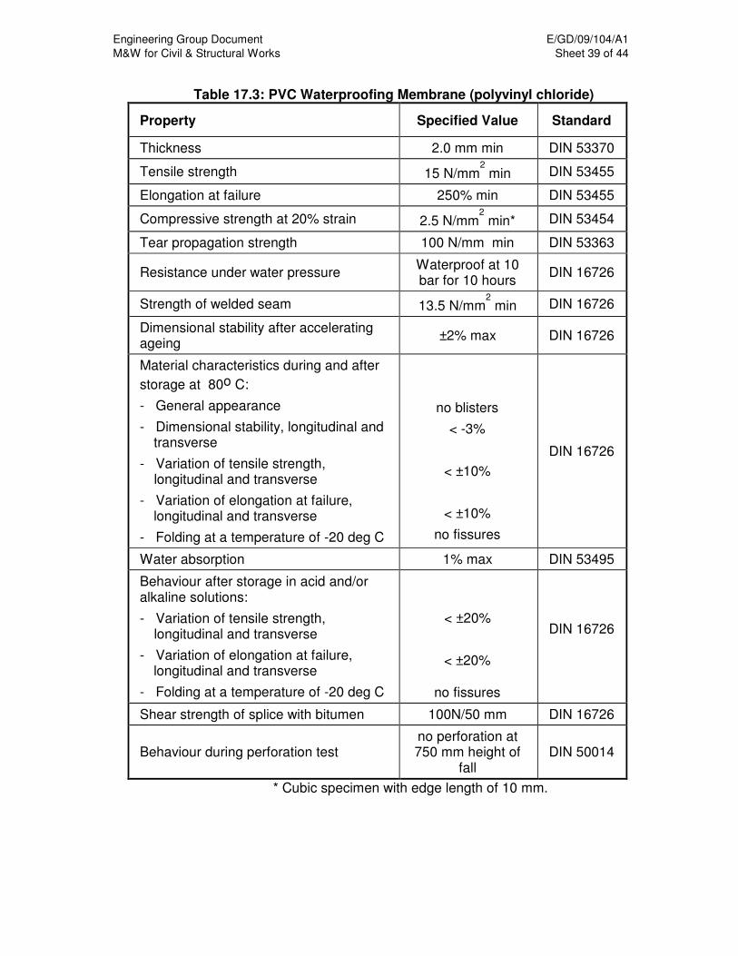
Engineering Group Document E/GD/09/104/A1
M&W for Civil & Structural Works Sheet 39 of 44
Table 17.3: PVC Waterproofing Membrane (polyvinyl chloride)
Property Specified Value Standard
Thickness 2.0 mm min DIN 53370
Tensile strength 15 N/mm2 min DIN 53455
Elongation at failure 250% min DIN 53455
Compressive strength at 20% strain 2.5 N/mm2 min* DIN 53454
Tear propagation strength 100 N/mm min DIN 53363
Resistance under water pressure Waterproof at 10 bar for 10 hours
DIN 16726
Strength of welded seam 13.5 N/mm2 min DIN 16726
Dimensional stability after accelerating ageing
±2% max DIN 16726
Material characteristics during and after
storage at 80o C:
- General appearance
- Dimensional stability, longitudinal and transverse
- Variation of tensile strength, longitudinal and transverse
- Variation of elongation at failure, longitudinal and transverse
- Folding at a temperature of -20 deg C
no blisters
< -3%
< ±10%
< ±10%
no fissures
DIN 16726
Water absorption 1% max DIN 53495
Behaviour after storage in acid and/or alkaline solutions:
- Variation of tensile strength, longitudinal and transverse
- Variation of elongation at failure, longitudinal and transverse
- Folding at a temperature of -20 deg C
< ±20%
< ±20%
no fissures
DIN 16726
Shear strength of splice with bitumen 100N/50 mm DIN 16726
Behaviour during perforation test no perforation at 750 mm height of
fall DIN 50014
* Cubic specimen with edge length of 10 mm.

Engineering Group Document E/GD/09/104/A1
M&W for Civil & Structural Works Sheet 40 of 44
Table 17.4: ECB Waterproofing Membrane (ethylene-copolymer bitumen)
Property Specified Value Standard
Thickness 2.0 mm min DIN 53370
Tensile strength 10 N/mm2 min DIN 53455
Elongation at failure 500% min DIN 53455
Compressive strength at 20% strain 2.5 N/mm
2 min* DIN 53454
Tear propagation strength 150 N/mm min DIN 53363
Resistance under water pressure
waterproof at 10 bar for 10 hours
DIN 16726
Strength of welded seam 7.2 N/mm2 min DIN 16726
Dimensional stability after accelerating ageing
±2% max DIN 16726
Material characteristics during and after storage at
80o C: - General appearance - Dimensional stability,
longitudinal and transverse - Variation of tensile
strength, longitudinal and transverse
- Variation of elongation at failure, longitudinal and transverse
- Folding at a temperature of -20 deg C
no blisters < -3%
< ±10%
< ±10%
no fissures
DIN 16726
Water absorption 1% max DIN 53495
Behaviour after storage in acid and/or alkaline solutions: - Variation of tensile
strength, longitudinal and transverse
- Variation of elongation at failure, longitudinal and transverse
- Folding at a temperature of -20 deg C
< ±20%
< ±20%
no fissures
DIN 16726
Shear strength of splice with bitumen
100N/50 mm DIN 16726
Behaviour during perforation test
no perforation at 750 mm height of fall
DIN 50014

Engineering Group Document E/GD/09/104/A1
M&W for Civil & Structural Works Sheet 41 of 44
17.7.2.4 Temporary Drainage System
a) In case of local water inflows, temporary drains may be installed on the rock/soil and shotcrete interface as local drainage in a manner acceptable to the Engineer.
b) Drainage strips placed on the rock/soil or shotcrete surface and subsequently covered by shotcrete or concrete are called rock drains. Rock drains shall be of a type acceptable to the Engineer.
c) Pipes passing through the membrane shall not be perforated drainage pipes and shall be sealed off by appropriate sealing flanges recommended by both, the supplier of the membrane and the pipe.
d) The Contractor shall provide a method statement for the Engineers acceptance on the installation and final curtailment of the temporary drainage system.
17.7.2.5 Accessories
Fixing material, flashing, reinforcement for expansion joints, sealing flanges and preparation of corners and intersections shall be as recommended by the manufacturer of the waterproofing membrane and fleece.
17.7.2.6 Finishing Layer
a) Prior to installation of the waterproofing system, shotcrete surfaces shall be smoothed with a finishing layer of shotcrete or a floated-off mortar layer. After application of the finishing layer or mortar layer, the final surface shall conform to the requirements of the membrane manufacturer.
b) The finishing layer shall consist of fine-graded shotcrete with rounded, uncrushed, aggregates. The maximum aggregate size shall be less than 4mm. The strength requirements shall be as specified for shotcrete. The required bond strength to the proceding shotcrete layer shall be a minimum 0.2MPa or as specified by the Engineer and shall be demonstrated by on-site trials as agreed with the Engineer.
c) In addition, the Contractor shall demonstrate to the Engineer by site trials that the finishing layer is capable of fulfilling the requirements with regard to surface roughness and overhead application.
d) The mix design shall be submitted to the Engineer for acceptance.
e) Where the main shotcrete does not contain steel fibre, the Contractor may propose to the Engineer to smoothen the final surface of the shotcrete as an alternative to applying a finishing layer. The Contractor shall demonstrate by site trials that he is able to achieve conformance with any requirements regarding surface roughness and application thickness.

Engineering Group Document E/GD/09/104/A1
M&W for Civil & Structural Works Sheet 42 of 44
17.7.3 Installation
17.7.3.1 Surface Preparation
a) All surfaces to which waterproofing is to be applied shall be clean, smooth and free from deleterious materials and projections.
b) The final surface prior to the installation of the waterproofing system shall fulfill the following requirements:
i) The ratio of the diameter to depth of surface irregularities shall be not less than 5:1.
ii) Transitions and intersections of underground structures shall be rounded off with a minimum internal radius of 500mm.
iii) The minimum thickness of the final finishing layer shall be 25mm.
c) Exposed steel parts such as rock bolts, if not intended to remain accessible, shall be covered with shotcrete. Protruding steel bars, wires, spacers, pipes etc. shall be cut flush with the surface unless treated with additional shotcrete. The radius of curvature of the finishing surface shall be not less than 0.2m.
d) After application of all additional layers of shotcrete and finishing layers, all surfaces shall be in accordance with the clearance requirements specified on the Drawings.
17.7.3.2 Application
a) Prior to the application of the waterproofing system (fleece and membrane), all surfaces to which it will be applied, will be inspected by the Engineer. The Contractor shall not continue with the application without the Engineer’s agreement.
b) All work for the application of the waterproofing system shall proceed from a safe platform. The design of the platform shall be submitted to the Engineer and safety officer in charge for acceptance.
c) The application of waterproofing elements shall follow the written instructions of the manufacturer. Generally, procedures shall be as follows:
i) Preparations: Special preparations will be required for waterproofing at intersections of underground structures and for projections passing through the membrane. They shall be carried out in accordance with the manufacturer's recommendation.
ii) Installing the fleece: The fleece shall be attached to the shotcrete surface using suitable fixings specified by the manufacturer. Two to four fixing elements shall be used per square metre. The fleece shall be laid with sufficient slack to avoid overstress during concreting. Adjacent sections of fleece shall be overlapped by 100mm minimum.
iii) Fixing of waterproofing membrane: The waterproofing membrane shall be installed to cover the fleece and shall be attached to the

Engineering Group Document E/GD/09/104/A1
M&W for Civil & Structural Works Sheet 43 of 44
fleece fixings by means of thermal welding. No perforation of the membrane shall be allowed for installation purposes, except where temporary drainage is required. The waterproofing membrane's outside (defined by colour contrasting) shall be laid towards the fleece and fixed to the fixing points with sufficient slack to prevent overstressing during concreting.
iv) Connecting the waterproofing membrane: Adjacent sheets of waterproofing shall be joined by a double seam weld. Connections to water stops and temporary drainage penetration shall be carried out according to drawings to be furnished by the supplier. To produce the weld, the Contractor shall use and operate appropriate equipment, which is acceptable to the Engineer.
d) The Contractor shall take particular precautions during installation of the reinforcement to ensure that the waterproofing membrane is not punctured or otherwise damaged. During installation of reinforcement, the Contractor shall use movable protective membranes between the reinforcement and the waterproofing membrane or other methods acceptable to the Engineer. Reinforcement spacer blocks shall be suitably sized to limit bearing pressures on the waterproofing membrane and shall be seated on a protective layer of backing material.
17.7.3.3 Storage
The Contractor shall take all necessary measures to the satisfaction of the Engineer for the storage of waterproofing membranes. It is the Contractor's responsibility to ensure proper storage so that no damage occurs to the membrane.
17.7.4 Testing and Acceptance of Membrane
17.7.4.1 General The Contractor shall not cast any section of the concrete lining before the
waterproofing work has been inspected and accepted by the Engineer. After the waterproofing membrane is erected, and in addition to the regular tests in accordance with the Method Statement for installation of the waterproofing membrane, the Contractor shall undertake acceptance tests in the presence of the Engineer to check the adequacy of the completed work.
17.7.4.2 Tests
17.7.4.2.1 General
a) The tests shall consist of close visual inspection of the membrane, joints and fixing points shortly before concreting, together with vacuum testing of suspect punctures and pressure testing of all double seam welds.
Engineering Group Document E/GD/09/104/A1
M&W for Civil & Structural Works Sheet 44 of 44
b) The Contractor shall provide suitable access and high intensity spot lighting for these tests and shall allow adequate time for testing within the construction program.
c) Prior to the installation of waterproofing system in the Works, the Contractor shall submit to the Engineer, for acceptance, details of the intended test procedures and equipment.
d) Records of the tests shall be submitted to the Engineer. Damage identified in the tests shall be brought to the Engineer's attention and highlighted. The Contractor shall propose remedial actions to the Engineer for acceptance.
17.7.4.2.2 Seam Test with Compressed Air
a) For seams between adjacent sheets of waterproofing membrane the testing for watertightness shall be carried out by means of compressed air pumped into the channel between two welds formed by the double welded joint. The channel shall be sealed at both ends and inflated to a pressure of 200kPa.
b) The length of welding seam tested in one test shall be in accordance with the manufacturer's recommendation with respect to the minimum and maximum length.
c) The test results are acceptable when the pressure does not fall more than 20kPa in a period of not less than 10 minutes.
17.7.4.2.3 Seam Test with Vacuum Equipment
a) Vacuum equipment shall be employed for the watertightness testing of areas of membrane of limited size such as special con-figurations of joints or local repairs with patches or where puncturing is suspected.
b) The testing equipment consists of a vacuum bell supplied by the membrane manufacturer, which is fitted tightly over the area to be tested and then evacuated by pumping. The test results are acceptable if a vacuum pressure of -20kPa can be achieved.
c) The test duration shall be in accordance with the recommendations of the membrane supplier/manufacturer.
17.7.4.2.4 Re-testing
Every possible care shall be taken not to damage the waterproofing membrane during or after installation. Any damages shall be repaired and re-tested before the pouring of the cast insitu concrete lining.

Engineering Group Document E/GD/09/104/A1 M&W for Civil & Structural Works Sheet 1 of 27
CHAPTER 18
PIPEWORKS AND PUMPS 18.1 GENERAL REQUIREMENTS 18.1.1 General 18.1.1.1 This Specification covers the pipework and pumps requirements for the
drainage works, sewerage, sanitary plumbing and water services. 18.1.1.2 The word “pipework” shall mean all pipes, drains, pipe fittings, valves,
hangers, brackets, anchors, supports, flexible connections, sleeves, and all related accessories connected there to for the complete system installation.
18.2 PIPEWORK 18.2.1 Installation 18.2.1.1 The Contractor shall construct all pipelines, drains and ducts including the
bedding, haunching and support as specified in this Specification and as shown on the Drawings unless otherwise directed by the Engineer.
18.2.1.2 Pipes and fittings shall be properly stored with sealed ends and protected
from possible damage before installation. They shall be thoroughly cleaned of rust and other foreign matter before installation. Final inspection being made after installation, but prior to backfilling or covering up in completion. They shall be well flushed through and the ends shall be covered to prevent the ingress of material that could obstruct the pipes. The cover shall be left in place until removal is necessary for completion of the system installation.
18.2.1.3 Unless otherwise specified or accepted by the Engineer, only one type of
pipe shall be used within any individual pipe length 18.2.1.4 Pipework shall not run through Lift Motor Room, Switch Rooms,
Transformer Rooms, Telephone Room and other rooms containing sensitive electrical/electronic equipment.
18.2.1.5 Pipework not serving protected lobbies and escape staircases shall not
pass through these areas. 18.2.1.6 Water pipes must be installed above other services pipes. When this is
unavoidable, protective pipe sleeves shall be provided at the portions where the other services pipes over cross the water pipes to prevent possible contamination of the water supply.
18.2.1.7 Excess pipes cut off during installation works shall not be used to join up
and fabricate into the length of pipes or other fittings.

Engineering Group Document E/GD/09/104/A1 M&W for Civil & Structural Works Sheet 2 of 27
18.2.1.8 The Contractor shall install pipework parallel to walls, clear of obstructions, preserving headroom and keeping passageways clear. All pipes shall be fixed at least 50mm away from the finished surface of the supporting structure.
18.2.1.9 Should site constraints prevent the installation of pipes or setting of
equipment at locations indicated on the Drawings, necessary minor deviations shall be allowed, as accepted by the Engineer.
18.2.1.10 Pipes shall be cut in a neat and workmanlike manner without damage to
the pipe. Pipe ends shall be reamed to remove any burrs. 18.2.1.11 Pipes shall be installed with the correct falls to ensure adequate venting
and draining. Vertical pipes shall be parallel to walls or column lines and shall be straight and plumb.
18.2.1.12 No pipe joints shall be permitted within the thickness of walls or floors etc. 18.2.1.13 Sockets shall face up the gradient. 18.2.1.14 Reducing sockets shall be used where a reduction in pipe size is required
to ensure proper drainage or elimination of air pockets. 18.1.1.15 Long sweep bends shall be used wherever physically possible. Square
elbows shall not be used. 18.2.1.16 The Contractor shall install 25mm diameter drain-off pipe with valve at
each low point of all water pipes. The drain-off pipe outlets shall be connected to the nearest floor waste.
18.2.1.17 The Contractor shall install automatic air vents at each high point of each
water line. 18.2.1.18 Pipe supports shall only be fixed to structural members, or to frames
supported by structural members. 18.2.1.19 Screw joints shall be made using properly cut tapered threads. The joints
shall be made watertight. 18.2.1.20 Flanges and unions shall be faced true. Flanges shall be provided with
approved gaskets and shall be made square and tight. Provide union or flange joints in each line immediately proceeding the connection to each piece or equipment or material requiring maintenance such as pumps, control valves, and other similar items. Gaskets shall conform to AMSE B16.21 and ASTM D2000.
18.2.1.21 Valves shall be installed in horizontal lines with stems either horizontal or
vertical. Isolation valves shall be installed at any other points indicated or required for draining, isolation, or sectionalizing purposes. Valves shall be installed such that maintenance access is maintained for all parts requiring service. Control valves shall be provided in water pipes to provide
Engineering Group Document E/GD/09/104/A1 M&W for Civil & Structural Works Sheet 3 of 27
complete regulation of plumbing fixtures and equipment. A valve schedule shall be prepared indicating location number and use.
18.2.1.22 All pipes shall be support independently at equipment locations so that the
equipment is not unduly stressed by the weight of the pipes or the effects of expansion.
18.2.1.23 Screwed or flanged connections shall be provided as required to facilitate
maintenance, repair and replacement. 18.2.1.24 Drawn bends shall not be used. 18.2.1.25 Where pipes pass through building movement joints, approved flexible
connections shall be provided to eliminate any stress which might be generated by such movements.
18.2.1.26 Contact of dissimilar material of pipes and its supports shall be avoided to
prevent corrosion resulting from galvanic action. 18.2.1.27 All fixtures, hangers, supports and brackets for pipes, trunking, conduits,
trays, equipment etc. shall be of hot dip galvanised to BS EN ISO 1461. 18.2.1.28 All threaded components including bolts, nuts, washers and inserts shall
be hot dip galvanised to BS 7371: Part 6 or sherardized to BS 7371: Part 8, Class S1.
18.2.1.29 Fixings shall be cast in to the building structure. If this is not practicable
they shall be secured to the structure by means of expansion bolts. 18.2.1.30 All pipes shall be clamped or fixed with split ring or clevis type hangers and
clamps. Where it is necessary to avoid vibration transmission a neoprene pad shall be provided between the fixing and the pipe. In systems where excessive vibration is envisaged during operations, dampers of proper/accepted design and installation shall be integrated onto the brackets/supports.
18.2.1.31 All pipework shall be checked against leaks and all valves free from
movement. 18.2.1.32 All pipework shall be supported by substantial bedding, purpose made
plinths, brackets, hangers or clips of accepted type and spacing as set out in Table 18.1.
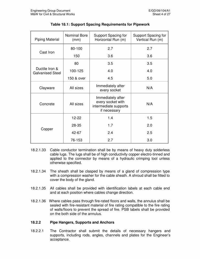
Engineering Group Document E/GD/09/104/A1 M&W for Civil & Structural Works Sheet 4 of 27
Table 18.1: Support Spacing Requirements for Pipework
Piping Material Nominal Bore
(mm) Support Spacing for Horizontal Run (m)
Support Spacing for Vertical Run (m)
Cast Iron 80-100
150
2.7
3.6
2.7
3.6
Ductile Iron & Galvanised Steel
80
100-125
150 & over
3.5
4.0
4.5
3.5
4.0
5.0
Clayware All sizes Immediately after
every socket N/A
Concrete All sizes
Immediately after every socket with
intermediate supports if necessary
N/A
Copper
12-22
28-35
42-67
76-153
1.4
1.7
2.4
2.7
1.5
2.0
2.5
3.0
18.2.1.33 Cable conductor termination shall be by means of heavy duty solderless
cable lugs. The lugs shall be of high conductivity copper electro-tinned and applied to the connector by means of a hydraulic crimping tool unless otherwise specified.
18.2.1.34 The sheath shall be clasped by means of a gland of compression type
with a compression washer for the cable sheath. A shroud shall be fitted to cover the body of the gland.
18.2.1.35 All cables shall be provided with identification labels at each cable end
and at each position where cables change direction. 18.2.1.36 Where cables pass through fire-rated floors and walls, the annulus shall be
sealed with fire-resistant material of fire rating compatible to the fire rating of walls/floors to prevent the spread of fire. PSB labels shall be provided on the both side of the annulus.
18.2.2 Pipe Hangers, Supports and Anchors 18.2.2.1 The Contractor shall submit the details of necessary hangers and
supports, including rods, angles, channels and plates for the Engineer’s acceptance.

Engineering Group Document E/GD/09/104/A1 M&W for Civil & Structural Works Sheet 5 of 27
18.2.2.2 Vertical pipes shall be supported with brackets to prevent swaying,
sagging, vibration and resonance, slacking or buckling between the supports or anchors.
18.2.2.3 The Contractor shall furnish anchors and guides for all horizontal and
vertical piping to control thermal movement, to prevent undue strain on branches, to provide proper performance of expansion loops and to avoid overloading of hangers and supports.
18.2.2.4 Anchors shall be positioned with regard to the change in direction of
pipework, expansion joints and loops so as to absorb stresses due to pipework expansion and internal pressure from transmission of such forces to the ground or structure at the relevant points. The type of anchors shall be hot-dipped galvanised steel, sherardized steel or stainless steel.
18.2.2.5 Additional brackets and supports shall be installed adjacent to pump
connections, valves, joints, changes in direction and other large items to prevent undue strains.
18.3 PIPE MATERIALS All materials for pipes, fittings and the associated installation requirements
shall be in accordance with the relevant Singapore Standard (SS), British Standard (BS), European Norm (EN) or other acceptable equivalent standards as described in ENV and PUB, codes of practices, standard specifications and standard drawings.
18.4 EXCAVATION FOR PIPEWORK The Contractor shall submit details of trench/manhole shoring works to the
Engineer for acceptance before the commencement of works and shall take full regard of the safety of the public, as well as the adjoining structures in his works. If the trenching depth exceeds the figure stated in the Factories Act, the Contractor shall obtain a Singapore Registered Civil Professional Engineer’s endorsement on the proposals/calculations.
18.5 BEDDING, HAUNCHING, LAYING AND BACKFILLING Unless otherwise specified or accepted by the Engineer, bedding,
haunching, laying of all pipes and backfilling of trenches shall be in accordance with the code of practises, M&W Chapter 19, Drainage Works, M&W Chapter 20, Sewerage and Sanitary Plumbing and M&W Chapter 21, Water Services.

Engineering Group Document E/GD/09/104/A1 M&W for Civil & Structural Works Sheet 6 of 27
18.6 PIPE SLEEVES 18.6.1 Where pipes pass through internal walls, floors, etc., the Contractor shall
provide pipe sleeves. All sleeves shall be of short pipe lengths of the same material as the services pipe and set during construction so that they project 20 mm beyond the finished surfaces.
18.6.2 All sleeves shall be of sufficient size to allow the free movement of the
pipe. The gap between the pipe and its sleeve shall be firmly packed with fibreglass or rockwool. However, for pipes/sleeves through fire barriers, the gap shall be firmly sealed with a suitable flexible material having a period of fire resistance equal to the fire barrier. The ends of the sleeve shall be caulked with non-hardening mastic (e.g. accepted rubber bitumen jointing compound) to the Engineer’s acceptance.
18.7 PIPES PASSING THROUGH EXTERNAL WALLS AND SLABS 18.7.1 Pipes passing through external walls, RC water tanks and slabs below
ground level and up to 500mm above finish floor level, shall be fitted with a puddle flange. The flange is to be cast or built into the midway point of the wall to create a water bar.
18.7.2 For pipe of 80mm diameter and above, the puddle flange shall have a
minimum diameter twice that of the pipe. 18.7.3 For pipe of 80mm diameter below, all puddle flanges shall have minimum
diameter of 150mm. 18.7.4 Where insulation against stray currents is required, the requirements are
as specified in M&W Chapter 25, Stray Current Control And Touch Voltage Protection.
18.8 MOVEMENT JOINTS Provision for movements due to expansion and contraction shall be made
with approved flexible connections to eliminate any stress whatsoever that may be caused by such movements.
18.9 PUMPS 18.9.1 General 18.9.1.1 This section specifies the manufacture and the installation requirements of
pumps. The requirements for electrical works are as specified in M&W Chapter 23, Electrical Works. All pumps shall be furnished by reputable and experienced manufacturers normally supplying this type of equipment and who can show evidence of having furnished such equipment that has been in successful operation for at least five years.
Engineering Group Document E/GD/09/104/A1 M&W for Civil & Structural Works Sheet 7 of 27
18.9.1.2 The Contractor shall be responsible for the final calculation of operating head based upon the characteristics of the pipework system actually installed. Performance curves for the pumps shall be provided with an operating range indicated. The number of starts/stops for a pump shall be set at 10 per hour.
18.9.1.3 Unless otherwise specified by the Engineer, pumps shall be so selected
that the design duty point is within 5% of the maximum efficiency achievable from the standard range of equipment available by the accepted manufacturer. It shall be non-overloading and the pump casing shall be so selected to have ample space to take an impeller one size larger than that capable of performing the design duty. The pump shall have a speed of not more than 1500 rpm (unless otherwise specified in Chapter 21). All pumps and motors shall be of minimum vibration and noise level during operation.
18.9.1.4 Facilities to select which pump is to be the duty and standby pump shall
be provided. The duty and standby pump shall be interchanged upon each operation cycle.
18.9.1.5 Leakage from the pump gland shall be drained to the nearest floor waste
by light gauge copper piping. 18.9.1.6 Pump curves for all pumps proposed shall be submitted. All curves
indicating excessive shut-off head shall not be accepted. 18.9.1.7 All pumps shall have mechanical seals. 18.9.1.8 All motors shall be sized at 115% of the maximum anticipated operating
duty. 18.9.1.9 Pumps shall be suitable for continuous 24 hour operation when handling
water in the range 4oC to 40
oC.
18.9.1.10 All pumps shall be tested in the factory to confirm performance data.
Certified shop test results shall be submitted to the Engineer for acceptance.
18.9.1.11 Pumps alignment shall be factory checked. The pump supplier shall also
verify by inspection on site that the alignment is correct after the pumps have been placed in position with pipe connections made and pipes filled with water.
18.9.1.12 Each complete pump unit, including the motor and drive, shall be factory
assembled by the pump manufacturer. All warranty and test certificates by the pump manufacturer shall be deemed to apply to the entire assembly.
18.9.1.13 For each pumping installation, the system shall be completed and
included all necessary wiring, valves, controls (emergency or dual power connections where applicable), starters, limit switches, float switches,
Engineering Group Document E/GD/09/104/A1 M&W for Civil & Structural Works Sheet 8 of 27
vibration isolators, base mountings, flexible connections and protection for the proper functioning and control of the respective systems.
18.9.2 Submissions The Contractor shall submit the following for acceptance by the Engineer.
(a) Detailed material specification, catalogue, technical data, pump performance curves
(b) Pump installation details, control panels, electrical and control single line diagram drawings
(c) Shop drawings showing the pump room and pipework layouts in 1:50 scale.
(d) Calculations on the mountings, inertia blocks, vibration isolators (e) Water hammer calculation of the complete system. The results shall
include the following: (i) Pipe profile with steady state, maximum and minimum hydraulic
grades lines. (ii) Time plot showing head, flow and speed at pump after shut-off
as a function of time. (f) Method statements and QA/QC procedures for installation, testing,
commissioning, cleaning and sterilization (g) Manufacturer’s certified test reports shall be provided before delivery
to site
Manufacturer performance warranty for pumps, motor, controlling and monitoring system and pump lifting devices.
18.9.3 Cold Water Pumps 18.9.3.1 All cold water transfer and booster pumps shall be of vertical multi-
centrifugal type with all vital parts made of stainless steel. 18.9.3.2 Each pump shall be provided with but not limited to the following;
(a) a gate valve and check valve at the discharge (b) a gate valve and strainer at the suction point (c) flexible connectors at the pump suction and discharge (d) eccentric reducer at the suction point (e) concentric reducer at the discharge (f) pressure gauges at the suction and the discharge (g) automatic air relief valve.
18.9.3.3 The diaphragm vessel, pump, motor, manifold with isolating and non-return valves, strainer, pressure gauges, pressure transmitters and pressure relief valve all mounted onto a same baseplate.
18.9.3.4 Pumps shall be mounted on a concrete plinth with vibration isolators and
inertia block. 18.9.3.5 Removable hot dip galvanised pump guards shall be provided between
pump and motor coupling.

Engineering Group Document E/GD/09/104/A1 M&W for Civil & Structural Works Sheet 9 of 27
18.9.3.6 The casings, impellers and shafts shall be solid stainless steel grade 316. Stainless steel sleeves of grade 316 shall be provided to protect the shaft in the water space and through the mechanical seals. The sleeves shall be keyed to prevent rotation and axial movement.
18.9.3.7 The bearings shall be of ball or roller type, protected against the ingress of
water, dirt and other matter. 18.9.3.8 Motors Vertical pumps shall be driven by elevated “in-line" TEFC squirrel cage
motor via extended vertical shaft complete with "universal" coupling. The pump motor shall be protected to IP 55 and with class F insulated windings.
18.9.4 Pressure Vessels 18.9.4.1 Pressure vessels shall be fitted with a pressure gauge and isolating valve
and shall be installed on the same mounting. The vessels shall be of adequate capacity to accommodate a considerable fluctuation in water demand by the system and shall minimize the start/stop cycles of the pumps.
18.9.4.2 The pressure vessels are to be constructed of steel plate, built and
stamped to ASME Standards. All ancillary internal parts are to be made of copper or bronze. The pressure vessels shall be able to withstand at least one and half times of the system working pressure.
18.9.4.3 A rubber diaphragm shall be provided in the pressure vessel separating
the fluid and the gas therein. 18.9.4.4 The vessels shall be pre-charged with nitrogen at the factory to a pressure
to suit the system. The pre-charge pressure shall be adjustable and a charging port with non-return device shall be provided in each vessel
18.9.5 Drainage Sump Pumps 18. 9.5.1 Type Drainage sump pumps shall be of vertical centrifugal submersible type.
The pumps shall be capable of handling solid fibrous material, heavy sludge and other matter found in drainage and storm water applications.
18.9.5.2 Function The drainage sump pumping system shall consist of standby and duty
pump(s), float switches, electrical and control wiring, all associated pipework, pressure gauges, and accessories necessary for the operation. The system shall include de-watering sump pump if required, which shall serve to dewater the sump for maintenance purposes.
Engineering Group Document E/GD/09/104/A1 M&W for Civil & Structural Works Sheet 10 of 27
18.9.5.3 Type of Motor The pump motors shall be of the squirrel cage induction type, suitable for
operating on 3 phase, 400 volt, 50 Hz, electrical supply. 18.9.5.4 Pump Capacity The pumps shall have adequate capacities to meet the pressure and flow
requirements of the systems and be acceptable to PUB/ENV. 18.9.5.5 De-watering Sump Pump 18.9.5.5.1 The pump shall be lowered to the sump base by means of the stainless
steel chain. 18.9.5.5.2 The pump shall have a base support. A 3-ply rubber hose shall be
provided at a pump discharge which shall be connected by means of a heavy-duty hose coupling.
18.9.6 Drainage Sump Pump Construction 18.9.6.1 Pump Construction 18.9.6.1.1 The volute casing discharge flange shall automatically and firmly via the
auto coupling rail system connect to the pump discharge connection that bolted to the floor of the sump and connected to the discharge line. No part of the pump unit shall bear directly on the floor of the sump. A sliding guide bracket shall be an integral part of the pump unit. There shall be no need to drain the sump or enter the sump to connect or disconnect the pump from the pump discharge connection.
18.9.6.1.2 Each pump shall be provided with an auto coupling system with guiding
rails extending from the top of the sump pit to the discharge connections complete with guide rails holding brackets, bolts and nuts etc, all which shall be of stainless steel.
18.9.6.1.3 All major parts, such as the stator casing, oil casing, sliding bracket volute
and impeller shall be of gray cast iron to ASTM No 35B, DIN GG-25 or BS Grade 260. The shaft shall be of made from solid stainless steel of a minimum grade 316. The impeller shall be vane shrouded, non-clogging design and be constructed with a through-let without acute turns.
18.9.6.1.4 All surfaces coming into contact with sewage shall be protected with a
sewage resistant coating. All exposed bolts and nuts shall be AISI type 304 stainless steel.
18.9.6.1.5 The pump body shall not be made up of dissimilar metals that would
cause galvanic corrosion. All mating surfaces of major parts shall be machined and fitted with nitrile rubber O-rings where water-tight sealing is required.
Engineering Group Document E/GD/09/104/A1 M&W for Civil & Structural Works Sheet 11 of 27
18.9.6.1.6 Machining and fittings shall be such that sealing is accomplished by automatic compression of the O-ring between two mating surfaces, without the requirement for a specific torque level.
18.9.6.1.7 Tolerances of all parts shall be such that replacement of any part is
possible without machining being required to ensure sealing as described above. No secondary sealing compound, grease or other devices shall be used.
18.9.6.1.8 The impeller shall have a sliding fit on the shaft and key driven or positive
drive of a conical split washer. Non-corrosive fasteners shall be used. 18.9.6.1.9 A wear ring system shall be installed to provide efficient sealing between
the volute and impeller. 18.9.6.2 Motors 18.9.6.2.1 The motor shall be of squirrel cage induction type. It shall have sufficient
capacity to drive the pump over its complete range of operation without overloading.
18.9.6.2.2 The pump motor shall be protected to IP 68, with class F insulated
windings rated at 155°C and with an effective motor cooling system. 18.9.6.2.3 The cable entry water seal design shall be such that it precludes specific
torque requirements to ensure a water-tight and submersible seal. Epoxies, silicones or other secondary sealing systems shall not be used.
18.9.6.2.4 Integral thermal sensors shall be used to monitor stator temperatures.
Float leakage sensors shall be incorporated to detect any leakage of liquid into the stator housing or into the cable entry of the pump. These shall be used in conjunction with and supplemented by external motor overcurrent and phase protection with supervision relays giving LED light status at the pump control panels.
18.9.7 Sewage Sump Pumps 18.9.7.1 Type Sewage sump pumps shall be of the centrifugal submersible type capable
of handling sewage water. 18.9.7.2 Pump Construction
The pump construction shall be as specified in clause 18.9.6.1. 18.9.7.3 Motors
The motor shall be as specified in clause 18.9.6.2.
Engineering Group Document E/GD/09/104/A1 M&W for Civil & Structural Works Sheet 12 of 27
18.9.8 Sewage Ejector Pumps 18.9.8.1 General 18.9.8.1.1 Each sewage ejector pumping system shall consist of duty and standby
pump(s), dewatering sump pump, sewage ejector tank and control panels. The sewage ejector pumps shall be of centrifugal submersible type installed dry on a concrete base and connected directly to the suction and discharge lines.
18.9.8.1.2 The sewage ejector pumps shall be capable of passing through solids of
at least 75 mm diameter and fibrous materials and heavy sludge. It shall be constructed with a uniform cross-section through the impeller with no acute turn.
18.9.8.1.3 The sewage ejector pump shall sit on rigid duck-foot stand mounted on a
concrete base. The duct foot bend shall be supplied with a clearing cum inspection cover to facilitate maintenance.
18.9.8.2 Pump Construction The pump construction shall be as specified in clause 18.9.6.1.3 to
18.9.6.1.9. 18.9.8.3 Motors
The motor shall be as specified in clause 18.9.6.2.
18.9.8.4 Sewage Ejector Tanks 18.9.8.4.1 The sewage ejector tanks shall be custom fabricated of stainless steel
plates grade 304 of not less than 4.5mm thickness. 18.9.8.4.2 The tanks shall be cylindrical in shape with rounded edges and filleted
corners provided with the following connections and appurtenances: (a) Two pump suction connection (b) An in flow connection (c) A by pass (d) A vent connection (e) A drain connection (f) An access manhole
18.9.8.4.3 The tanks shall be designed to withstand twice the working pressure. 18.9.8.4.4 All field joints and connections shall be secured by bolting. All bolts, nuts
and washers shall be of grade 304 stainless steel. To ensure water tightness, suitable gaskets of the appropriate thickness shall be incorporated in the connecting flanges.
Engineering Group Document E/GD/09/104/A1 M&W for Civil & Structural Works Sheet 13 of 27
18.9.9 Pump Installation 18.9.9.1 The Contractor shall install pumps and appurtenances in the space
provided and easy for maintenance. 18.9.9.2 Pump installation shall be completed with adequate facilities for
maintenance and future replacement of pumps and other associated equipment.
18.9.9.3 The Contractor shall provide the steel framework, inertia blocks and
vibration isolators for pumps. 18.9.9.4 The Contractor shall provide the plinth structural steel and other necessary
equipment and material for the proper installation and delivery of the equipment.
18.9.9.5 The Contractor shall provide supports to both sides of the flexible
connection where appropriate to prevent undue strains on the pumps. Such supports shall be mounted so as not to transmit vibration to the building.
18.9.9.6 Where appropriate each pump shall be fitted with air cocks, drain plugs
and a pressure gauge on both sides of the pump. The gauges shall be mounted on a gauge board on the wall.
18.9.9.7 The Contractor shall provide hot dip galvanized, angle iron and wire mesh
guards to all exposed shafts, couplings and moving parts. The guard shall be robust, easily removable and complete with lifting handles.
18.10 PRESSURE SWITCHES 18.10.1 Pressure switches, including differential pressure switches shall be
electrically operated and of diaphragm, bellows or bourdon tube operating type and shall have adjustable set points with an integral time delay device.
18.10.2 The pressure range shall be graduated in metric units and shall not
exceed the anticipated maximum operating pressure or maximum operating differential pressure at any point in the pipe by more than 50%.
18.11 WATER LEVEL CONTROLLERS Water level controllers shall be provided and fitted in cold water tanks for
monitoring the water levels and give the appropriate control/warning signals. Water level sensors shall be of sensing electrode type, controller containing the switching circuitry and control relays and suitable for drinking and cooling water.

Engineering Group Document E/GD/09/104/A1 M&W for Civil & Structural Works Sheet 14 of 27
18.12 LIFTING SYSTEM 18.12.1 The Contractor shall supply, install, test and commission the lifting
systems. The lifting system shall be provided with equipment warranty for eighteen (18) months warranty from the date of issue of the Certificate of Substantial Completion.
18.12.2 The lifting system shall include the chain block and hoists complete with I-
beam for the lifting of the heaviest pump. The Contractor shall size and select the hoisting system to enable a safe installation, maintenance and removal of the pumps subject to the approval of the Engineer.
18.12.3 All lifting system shall be tested to 1.5 times the working load in the
direction of pull appropriate to its proposed use. The Contractor shall submit a certificate of load test endorsed by Professional Engineer for the lifting equipment and complete with Ministry of Manpower registration number and label.
18.12.4 Upon acceptance of the test, the Contractor shall supply and install
accepted signs to indicate the safe working load and the allowable pull directions. The location of installation shall be to the Engineer’s acceptance.
18.13 NOISE & VIBRATION CONTROL 18.13.1 Noise Levels 18.13.1.1 It is the intent of this section that the noise levels due to mechanical
equipment and related services shall comply with the relevant noise level criteria including the control of all noise breakout via pipework.
18.13.1.2 The Contractor is to ensure that the equipment of the lowest available
sound power levels shall be selected. The Contractor shall supply and install noise control devices necessary to comply with the noise criteria.
18.13.1.3 The contractor shall provide certified sound power level spectra taking into
consideration room effect allowances for all noise emitting equipment for acceptance.
18.13.1.4 Noise emanating from mechanical plant room and crossing the site
boundaries shall not exceed statutory requirements. 18.13.1.5 The noise level in the pump rooms shall not exceed the maximum
allowable sound pressure level of 85dBA. 18.13.2 Not Used 18.13.3 Vibration Isolators 18.13.3.1 General
Engineering Group Document E/GD/09/104/A1 M&W for Civil & Structural Works Sheet 15 of 27
18.13.3.1.1 All rotating or vibration emitting equipment shall be mounted on vibration
vibrators so that a minimum of 90% of the vibrating forces are isolated from the supporting structure.
18.13.3.1.2 The maximum allowable vibration for pumps shall be in accordance with
ISO 2373 and shall not exceed 0.7mm/s RMS. 18.13.3.1.3 All vibration isolators of similar type shall be supplied by one
manufacturer. All vibration isolators selections shall be subject to the acceptance of the Engineer.
18.13.3.1.4 All vibration isolators and accessories shall be supplied by
manufacturers experienced in the design and construction of such equipment.
18.13.3.2 Pumps 18.13.3.2.1 Unhoused type steel springs in series with 2 layers of 8mm thick 40
durometer neoprene waffle pads and 1mm thick steel shim of 50mm minimum total static deflection. There shall be no rigid ties to the structure, all connections shall be looped or flexible.
18.13.3.2.2 Inertia block minimum 1:1.5 ratio to be provided. Inertia block shall be
sized to obtain the minimum specified inertia block/equipment mass ratio. Thickness of the inertia block shall be 150mm minimum and need not exceed 300mm. The inertia blocks shall support the pipework up to and including the first elbow before the vertical risers.
18.13.3.2.3 Flexible connection shall be provided in pipework connected to pumps
as indicated on the drawings. The flexible connection shall be able to withstand 2.5 times of the working pressure and free from vibration fatigue.
18.13.3.3 Piping For a distance of 40 pipe diameters from the equipment, spring and
neoprene hangers providing a deflection similar to the equipment mounts shall be used. For the first three mounts, hangers shall be of the type which allow for deflection adjustment. All vertical riser and dropper pipework shall be isolated with resilient pipe guides or mounts with neoprene in shear mounts in angle or channel steel frames. For all other piping one layer 8mm thick neoprene waffle pad sleeve between pipe and clamp or supports shall be used.
18.13.3.4 Vibration Isolators 18.13.3.4.1 Ribbed or waffle pattern neoprene pads
Engineering Group Document E/GD/09/104/A1 M&W for Civil & Structural Works Sheet 16 of 27
(a) Vibration isolation pads of a cross ribbed or waffle pattern shall be 9.5mm and 8mm thick respectively and made from 40 durometer neoprene unless otherwise specified.
(b) For typical applications the 40 durometer type neoprene pads shall
be loaded to a surface weight of approximately 35,000kg/m2.
Where two or more layers of neoprene pads are used, individual layers shall be separated by 20G thick galvanised steel shims. The total deflection is determined by multiplying the single layer by the number of individual layers of neoprene pads. Unless otherwise specified no holding down bolts nor adhesive is to be used with neoprene pads.
18.13.3.4.2 Rubber in shear mounts
(a) Rubber in shear mountings shall have separate steel top and base plates completely embedded in oil resistant neoprene with non skid mounting surfaces complete securing bolts. The rubber in shear mountings shall be sized a minimum static deflection of 6mm and shall be colour coded for identification of load capacity.. The equipment shall be bolted securely to the isolator unless otherwise shown and approved.
(b) When holding-down bolts are used, they shall only be tightened a
half turn more than hand tight. If leveling is necessary this shall be done with galvanised shims which, if placed on top, shall cover the full top surface of the mounting.
18.13.3.4.3 Spring Isolators
(a) Spring type isolators shall be free standing and laterally stable without any housing and in series with two layers of ribbed or waffle pattern neoprene pads between the base plate and the support.
(b) All mountings shall be selected to support the actual loads with the
minimum spring deflections as specified for the type of equipment without exceeding the manufacturers maximum rated loads and rated deflections under any operating condition. In the selection of the springs the Contractor shall also take into account the weight distribution of the equipment under normal operating conditions, weight of unsupported pipes and ducts and any dynamic forces due to fluid movement, torque reaction and starting and stopping. The Contractor shall show on the shop drawings submitted, the make and model, number of the isolators to be used and their individual calculated loads.
(c) All mountings shall have leveling bolts that shall be rigidly bolted to
inertia blocks or base frames, which in turn shall be rigidly attached to the equipment.
Engineering Group Document E/GD/09/104/A1 M&W for Civil & Structural Works Sheet 17 of 27
(d) Spring diameters shall be no less than 0.8 of the compressed height of the spring at rated load and horizontal spring stiffness shall be approximately equal to vertical stiffness. Springs shall have a minimum additional travel to solid equal to 50% of the rated deflection, and in this condition shall not exceed the elastic limit of the spring. All springs shall be mounted with adequate clearance from brackets and base frames for easy cleaning and shall be clearly in view for critical inspection.
(e) All isolator metal springs and fittings are to be galvanised or epoxy
coated against corrosion.
18.13.3.4.4 Hangers – Spring and Rubber in Shear
(a) Hangers shall be compatible with other vibration isolation equipment. Where required deflections are less than 12mm, hangers shall be provided with rubber in shear isolating elements. Where required deflections are greater than 12mm, hangers shall be provided with spring in series with rubber in shear vibration isolating elements.
(b) The hanger casing shall be designed for the design operating load. (c) Springs shall have a resilient rubber insert to isolate them from the
hanger casing. (d) For single spring assembly, spring diameters and the casing lower
hole size shall be large enough to permit the hanger rod to swing through 30
o arc without touching the case.
18.13.3.5 Bases 18.13.3.5.1 Steel Base Frame Where specified, equipment or the assembly of equipment, shall be
mounted on or be integral with structural steel bases. The entire assembly shall be supported on vibration isolators without distortion of the base frame or mis-alignment of the equipment. There shall be adequate clearance (minimum 20mm) all round the isolator to ensure that there is no contact between any isolator and any part of the mounted assembly. The clearance between the base-frame and the floor or plinth shall be at least 40mm and 100mm maximum.
18.13.3.5.2 Inertia Blocks
(a) Inertia blocks shall be made of concrete and installed where specified.
(b) The length and width of the inertia block shall be at least 200mm
greater than the length and width of the supported equipment, except where otherwise specified. The weight of the inertia block
Engineering Group Document E/GD/09/104/A1 M&W for Civil & Structural Works Sheet 18 of 27
shall be at least equal to the operating weight of the equipment supported.
(c) The base shall consist of a concrete slab cast into a welded steel
base-frame assembly. Frames shall be welded steel channels, of minimum 150mm thickness or the same thickness as the inertia block and shall be reinforced with welded in 12mm steel reinforcing rods or angles at 150mm centers each way. Anchor bolts shall be fixed into position, and housed in steel bolt sleeves to allow minor bolt location adjustments or alternatively, pockets shall be cast into inertia block to permit the later insertion of anchor bolts.
(d) Steel channel isolator brackets shall be welded directly to channel
frames, and suitably located to accommodate the height of the deflected springs and inertia block clearance with plinth.
(e) There shall be adequate clearance (minimum 20mm) all round the
springs to assure that there is no contact between any spring and any part of the mounted assembly for any possible alignment or position of the installed inertia block. The clearance between inertia block and floor or plinth shall be in the range 50 to 100mm.
(f) The Contractor shall supply and install all welded structural steel
and reinforcement required for the inertia blocks. All installation work concerning these items are included with this sub-contract.
(g) All structural bases and inertia blocks shall be designed by
Singapore Registered Structural Professional Engineer. Certificates shall be provided that the design of the bases is satisfactory for the duty.
18.14 TESTING & COMMISSIONING AND MAINTENANCE 18.14.1 General Requirements The Contractor shall carry out all the necessary testing and
commissioning in addition to those called for elsewhere in this Specification. This shall comprise of tests at the manufacturer's works, site tests during construction, commissioning, acceptance tests and tests as required by authorities.
18.14.2 Execution 18.14.2.1 The Engineer shall be invited to witness all tests. Such tests, whether or
not witnessed by the Engineer, shall be properly certified in a manner acceptable to the Engineer.
18.14.2.2 Test records, certificates and performance curves shall be supplied for
all tests. The information given on such test certificates and services shall be sufficient to identify the material or equipment.
Engineering Group Document E/GD/09/104/A1 M&W for Civil & Structural Works Sheet 19 of 27
18.14.2.3 The Contractor shall be responsible to supply all testing equipment,
instruments, materials and labour necessary for the testing and commissioning of the entire system.
18.14.2.4 The Contractor shall notify the Engineer in reasonable time to enable
him to be present for the final testing of the complete system. The Contractor shall repair defects disclosed by the tests or, if required by the Engineer, replace defective work with new work without additional cost. The tests shall be carried out in stages as required to facilitate work by others.
18.14.2.5 The Contractor shall make good the work of other trades disturbed or
damaged as a result of his tests. 18.14.3 Inspection and Testing During Manufacture 18.14.3.1 The Engineer shall be entitled at all reasonable times during
manufacture to inspect, examine and test the materials and performance of all equipment. Such inspection, examination and testing shall not release the Contractor from any obligation under the Contract.
18.14.3.2 Facilities and equipment shall be provided for the Engineer to check the
performance, dimensions, workmanship and finishes of all equipment. The manufacturer shall furnish the original copy of certificates giving records of tests carried out.
18.14.3.3 Works, inspections and testing of major equipment items shall be carried
out in accordance with the relevant standards. 18.14.4 Testing and Commissioning at Site 18.14.4.1 Notice The Contractor shall give to the Engineer, in writing, 14 days' notice of
the date of testing at site. 18.14.4.2 Records Records shall include all initial insulation resistance and continuity
readings, etc., as applicable, to enable comparison to be made subsequently during the life of the equipment.
18.14.4.3 Licensed Electrical Worker (LEW) The Contractor shall engage a LEW of an appropriate grade, for the
purpose of certifying the testing and commissioning of the electrical works. The LEW shall also ensure that safe conditions are provided and maintained when work is required to be undertaken after turn-on.
Engineering Group Document E/GD/09/104/A1 M&W for Civil & Structural Works Sheet 20 of 27
18.14.4.4 Preliminary Commissioning Checks 18.14.4.4.1 The Contractor shall ensure that all equipment is thoroughly cleaned,
lubricated and checked for serviceability. 18.14.4.4.2 The contractor shall thoroughly flush out all pipework to ensure that all
objects are removed. 18.14.4.5 Commissioning 18.14.4.5.1 The Contractor shall regulate and calibrate all systems in the entire
installation. 18.14.4.5.2 All systems shall be tested and commissioned in accordance with the
details in the relevant clauses of the M&W Specification. 18.14.4.6 Final Acceptance Tests 18.14.4.6.1 Following commissioning of the entire installation, and prior to issue of
the Certificate of Substantial Completion, the Contractor shall carry out final acceptance tests in accordance with a program to be accepted by the Engineer.
18.14.4.6.2 Should the results of the acceptance tests show that any plant, systems
and/or equipment fail to perform to the efficiencies or other performance figures as given in the M&W Specifications, the Contractor shall adjust, modify and if necessary replace the equipment in order to achieve the required performance.
18.14.4.7 Integrated Testing & Commissioning After the works have been accepted, the Contractor shall be required to
carry out or assist in carrying out integrated testing and commissioning tests with the interfacing contractors.
18.14.4.8 As-Built Drawings, Operation and Maintenance Manuals Upon the satisfactory completion of all the testing and commissioning,
the Contractor shall submit the following within four weeks for the Engineer’s acceptance: (a) Test records and as-built drawings endorsed by the PE/LEW (b) Operation and maintenance manuals
18.15 PAINTING, COLOUR CODING AND LABELLING 18.15.1 General Requirements 18.15.1.1 Painting and labelling shall not be applied before the relevant systems
have been satisfactorily tested.
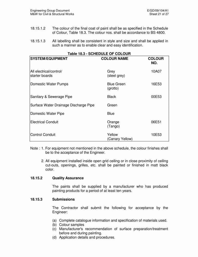
Engineering Group Document E/GD/09/104/A1 M&W for Civil & Structural Works Sheet 21 of 27
18.15.1.2 The colour of the final coat of paint shall be as specified in the Schedule
of Colour, Table 18.3. The colour nos. shall be accordance to BS 4800. 18.15.1.3 All labelling shall be consistent in style and size and shall be applied in
such a manner as to enable clear and easy identification.
Table 18.3 - SCHEDULE OF COLOUR
SYSTEM/EQUIPMENT COLOUR NAME COLOUR NO.
All electrical/control/ Grey 10A07 starter boards (steel grey) Domestic Water Pumps Blue Green 16E53 (grotto) Sanitary & Sewerage Pipe Black 00E53 Surface Water Drainage Discharge Pipe Green Domestic Water Pipe Blue Electrical Conduit Orange 06E51 (Tango) Control Conduit Yellow 10E53 (Canary Yellow)
Note : 1. For equipment not mentioned in the above schedule, the colour finishes shall
be to the acceptance of the Engineer. 2. All equipment installed inside open grid ceiling or in close proximity of ceiling
cut-outs, openings, grilles, etc. shall be painted or finished in matt black color.
18.15.2 Quality Assurance The paints shall be supplied by a manufacturer who has produced
painting products for a period of at least ten years. 18.15.3 Submissions The Contractor shall submit the following for acceptance by the
Engineer:
(a) Complete catalogue information and specification of materials used. (b) Colour samples (c) Manufacturer's recommendation of surface preparation/treatment
before and during painting. (d) Application details and procedures.

Engineering Group Document E/GD/09/104/A1 M&W for Civil & Structural Works Sheet 22 of 27
18.15.4 Painting 18.15.4.1 The following items shall be painted:
(a) All services installed in exposed/visible locations and within the equipment plant room including pipework, external cladding, cable trays/trunking/conduits, flanges, valves, couplings, etc.
(b) All equipment. (c) All control/electrical panels, starter panels, marshalling boxes.
18.15.4.2 The following items are not required to be painted:
(a) All stainless steel and chrome-plated surfaces. (b) All fibreglass and plastic surfaces.
18.15.5 Paint Application for Galvanised Steel and Mild Steel Surfaces 18.15.5.1 The following shall be applied to all galvanised and mild steel surfaces to
be painted.
(a) Primer Oleoresinous varnish based primer pigmented with zinc chromate and extenders suitable for use.
(b) Undercoat Linseed oil modified alkyd, pigmented appropriate shade. (c) Finish Coats Long linseed oil modified alkyd with glossy finish and fungus
resistant characteristics. 18.15.5.2 The Contractor shall provide 1 primer, 1 undercoat and 2 finish coats. 18.15.5.3 Minimum dry film thickness (DFT) shall be in accordance to the paint
manufacturer's recommendation. 18.15.6 Paint Application for Copper Pipework All copper pipes and fittings shall be polished bright and finished with a
coat of clear lacquer. 18.15.7 Paint Application for All Other Metallic Surfaces 18.15.7.1 The following shall be applied to all other metallic surfaces which have
specified painting requirements. Primer: 1 coat of rust inhibitive alkyd pigmented with zinc chromate,
yellow oxide and extenders. Undercoat: 1 coat of modified alkyd to suit primer and overcoat. Finish coats: 2 coats of modified alkyd enamel.

Engineering Group Document E/GD/09/104/A1 M&W for Civil & Structural Works Sheet 23 of 27
18.15.7.2 Dry film thickness shall be in accordance to manufacturer's
recommendation. 18.15.7.3 Cast iron or ductile iron pipes which have been previously dipped at the
factory shall be painted with 2 coats of bituminous paint or aluminum sealer prior to application of finishing coats.
18.15.8 Painting of Equipment 18.15.8.1 All equipment casings and metal parts shall be pretreated before
painting/coating in factory to the manufacturer’s recommendations to suit the intended duty and operating requirements.
18.15.8.2 If any equipment rusts due to inadequate painting, poor workmanship,
incorrect handling during transportation, storage and installation, the Contractor shall be required, at his own expense, to replace all damaged parts or components and repaint the whole equipment. Details of repairs shall be submitted to the Engineer for acceptance
18.15.9 Colour Bands/Legends 18.15.9.1 All insulated pipework without cladding shall have identification colour
bands as specified for the relevant services in Table 18.3 Schedule of Colour.
18.15.9.2 Colour bands shall be provided at intervals not exceeding 2m and
wherever necessary at bends, tees etc. and when pipes pass through from one room or zone to another. When two or more pipes run in parallel, the colour bands for each pipe shall be at the same location.
18.15.9.3 Bands shall be of 100mm width and colour to identify individual services. 18.15.9.4 All un-insulated pipework and externally clad insulated pipework shall
have properly painted colour legend to identify each individual service. Spacing of colour legend shall be the same as colour bands.
18.15.9.5 Colour bands and legends are not required for branch water supply, soil,
waste vent and gas pipes within toilet areas, kitchens and serving individual floor trap/drain and sanitary/plumbing fittings.
18.15.10 Labelling 18.15.10.1 All plant and equipment shall be labelled to show its duty, service and
asset number. All such labelling shall correspond to schedules, diagram, etc. to be provided as part of the as-built drawings. Labels shall generally be of white Traffolite laminated white/black/white and engraved with black lettering, or as otherwise accepted by the Engineer
18.15.10.2 Valves of diameter 65mm and above throughout the installation shall be
fitted with labels in the form of white Traffolite discs laminated

Engineering Group Document E/GD/09/104/A1 M&W for Civil & Structural Works Sheet 24 of 27
white/black/white and engraved with black lettering. Labels shall either be secured under the hand wheel or fixed to the body of the valve by means of link brass chain.
18.15.10.3 Every indicating light, switch, terminal and breaker in the control and
electrical board shall be labelled. 18.15.11 Directional Arrows Lettering 18.15.11.1 Directional arrows and lettering to indicate the direction of flow or return
shall be black where the background colour is other than black. Where the background colour is black, the directional arrows and lettering shall be white.
18.15.11.2 Directional arrows and lettering shall be painted on the visible sides of all
pipework at 2.0m centres and adjacent to valves and tees. 18.15.12 Application 18.15.12.1 Prior to the application of painting, all metal surfaces shall be dry and free
of any contaminants such as dirt, dust, oil, rust, wax or scale that would interfere with the development of full adhesion by a paint and coating system. Proper procedures shall be followed, as outlined below, and in consideration of the type and concentration of contaminants and the specific requirements of the protective coating system to be applied to any given surface. The Contractor shall follow in strict accordance with the surface preparation requirements as recommended by the Paint Manufacturers to a finish standard of BS or Steel Structure Painting Council U.S.A. or approved equal.
18.15.12.2 The Contractor shall remove all dirt, grease, oil, loose rust and other
contaminants on mild steel or other ferrous metal surfaces by washing the surface with a suitable chemical solution or etching solution. He shall rinse thoroughly and allow to fully dry as recommended by the paint manufacturers.
18.15.12.3 The Contractor shall scrape or wire brush mild steel, ductile iron or other
ferrous metal surfaces and crevices to remove rust and loose scale and welding slag or splatter. For moderately rusted surfaces, it shall be cleaned in a proper manner, as accepted by the Engineer, to achieve a rust free and clean surface. The Contractor shall replace all heavily rusted parts or replace the whole component should the heavily rusted parts be difficult or impossible to be removed.
18.15.12.4 Surfaces which have been cleaned, pretreated, dried or otherwise
prepared shall be painted with the first few coats well before any deterioration of the prepared surface takes place. The Contractor shall obtain instruction or inspection from the Engineer before proceeding with application of the primer.
Engineering Group Document E/GD/09/104/A1 M&W for Civil & Structural Works Sheet 25 of 27
18.15.12.5 The Contractor shall follow in strict accordance all coating procedures recommended by the manufacturer of the coatings. The Contractor shall also provide all chemical treatment if necessary before the application of the primer in order to achieve good adhesion of the paint to the substrate for the intended application. In addition, all safety rules and regulations, local laws, paint manufacturers' recommendations etc. shall be strictly observed by personnel engaged in the storing, handling, use and application of paints, thinners and solvents so as to provide an acceptable level of safety from fire and health hazards.
18.15.12.6 All coatings and painting materials shall be delivered to the site in their
original unbroken containers plainly marked with the brand name and code of the product and the name of the manufacturer. All coatings used shall be applied using a method recommended by the manufacturer and accepted by the Engineer and without being extended or modified other than as provided for in the manufacturer's printed instructions. Preparation and condition of all surfaces to be coated shall be as described in the manufacturer's literature.
18.15.12.7 For ease of inspection and measurement, each successive coat applied
to a surface shall be in such a tint as to make it easily distinguishable from the preceding coat.
18.15.12.8 Hardware accessories, machined surfaces, plates, lighting fixtures and
similar items in place prior to cleaning and painting and not intended to be painted shall be protected during surface preparation and painting operations or shall otherwise be removed and replaced upon completion of each area or work.
18.15.12.9 All lagged surfaces shall be perfectly dry and dust free prior to painting.
The appropriate primer shall be applied as soon as possible after cleaning.
18.15.12.10 Paints or other finishes shall not be applied to wet or damp surfaces.
Painting shall not be done in rain, high relative humidity and high ambient temperature as recommended by the manufacturer. All paints shall be applied under favorable conditions by skilled painters and shall be brushed out carefully to a smooth, even coating without runs and sags. Enamel shall be flowed on evenly and smoothly. Each coat of paint shall be allowed to dry thoroughly, not only on the surface but also through the thickness of the paint film before the next coat is applied. Finish surfaces shall be uniform in finish and colour and free from flash spots and brush marks. In all cases, the paint films produced shall be acceptable, in all respects, to the Engineer
Engineering Group Document E/GD/09/104/A1 M&W for Civil & Structural Works Sheet 26 of 27
18.15.12.11 Spraying with adequate apparatus may be substituted for brush
application of those paints and in those locations for which spraying is suitable with permission from the Engineer
18.15.12.12 The Contractor shall not only protect his work at the time, but shall also
protect all adjacent work and materials by the use of sufficient drop cloths during the progress of his work. Upon completion of the work, he shall clean up all paint spills, oil, and stains from floors, glass, hardware, and similar finished items.
18.15.12.13 Drying time shall be construed to mean "under normal conditions".
Where conditions are other than normal due to weather or painting being done in a confined space, additional drying time will be necessary. Additional coats of paint shall not be applied, nor shall units being painted be placed in service, until all coating systems are thoroughly cured.
18.15.12.14 Paint shall be applied so as to obtain a coverage per gallon not greater
than that recommended by the manufacturer. Manufacturers printed literature shall be considered as part of this Specification.
18.15.12.15 Thinning, when necessary, shall be done only with products of the
approved coatings manufactured and designated for the particular coating in use strictly in accordance with the manufacturer's instructions. Addition of any thinner shall be with the full knowledge and acceptance of the Engineer.
18.15.12.16 If paints are thinned for spraying, the film thickness after application shall
be the same as though the unthinned paint were applied by brush. That is, the addition of a thinner shall not be used as a means of extending the coverage of the paint, and the area covered shall be no greater than the area which would have been covered with the same quantity of unthinned paint.
18.15.12.17 The Contractor shall obtain approval before proceeding with the
remedial work if the metal coating is defective. 18.15.12.18 The following treatment process shall be applied for all galvanized
surfaces found defective: (a) Wash with white spirit or other suitable chemical solution. (b) Rinse thoroughly and allow to fully dry as recommended by the
manufacturers. (c) Scrap or wire brush or power tool clean to remove scale and loose
rust etc to obtain a suitable surface for coating. (d) Treat prepared surface with etch primer or approved chemical
before applying primer to the galvanized surfaces to prevent scaling in future.

Engineering Group Document E/GD/09/104/A1 M&W for Civil & Structural Works Sheet 27 of 27
18.15.12.19 Paints and application details for surfaces other than specified above should be submitted to the Engineer for acceptance.
18.16 SPARES, STANDARDISATION AND TOOLS 18.16.1 The Contractor shall recommend the spare lists with the cost and
quantity. 18.16.2 Screw threads shall be of standard ISO metric sizes. 18.16.3 In order to limit the number of spares to be held for maintenance of the
installation, all similar units of equipment shall be supplied by the same manufacturer and of the same type of equipment using the same common components.
18.16.4 The equipment shall be designed to allow installation, handling and
maintenance to be carried out using conventional tools. The use of special tools shall be restricted to a minimum.
18.16.5 Two sets of special tools shall be provided. 18.17 REQUIREMENT FOR ELECTROMAGNETIC COMPATIBILITY 18.17.1 All electrical and electronic equipment shall be designed and
constructed to operate without degradation of quality, performance or loss of function in the electromagnetic environment of the locations of its intended use.
18.17.2 The electromagnetic environment includes emissions from transit
system, military installations, high voltage transmission and distribution equipment, TV, radio broadcasting equipment, telecommunication equipment and many types of domestic or publicly carried electrical equipment. All such equipment and systems shall neither interfere with nor be interfered by the equipment and systems installed by the Contractor.
18.17.3 The equipment shall not produce intolerable emissions within its
environment and shall comply with the appropriate internationally recognised EMC standards (e.g. EN50121)
18.17.4 All electrical apparatus including commutator motors, motors, starters,
contactors and electronic control devices shall be fitted with means for suppressing the interference frequencies generated (whether of a continuous or intermittent nature).

Engineering Group Document E/GD/09/104/A1 M&W for Civil & Structural Works Sheet 1 of 10
CHAPTER 19
DRAINAGE WORKS 19.1 GENERAL 19.1.1 General The works covered under these specifications shall include the design,
supply, installation, testing and commissioning of all Drainage works. 19.1.2 Design requirement The Contractor shall perform all design functions necessary for the
development, manufacture/procurement, installation and site testing of systems, sub-systems and components to provide complete and operable installations.
19.1.3 Workmanship
Workmanship shall be to the acceptance of the Engineer, who shall have the right to reject any material he may deem unfit for use or installed in a non-workmanlike manner.
19.1.4 Standards, Codes and Regulations 19.1.4.1 The design, manufacture, supply, installation, testing and commissioning of
the Drainage works shall be governed by all applicable latest editions of local codes, regulations, standards and requirements issued by all the local statutory authorities and agencies which shall include the following:
a) Public Utilities Board (PUB) b) Land Transport Authority (LTA) c) Ministry of the Environment (ENV) d) Singapore Productivity and Standards Board (PSB) e) Energy Market Authority (EMA)
19.1.4.2 The Contractor shall apply for all necessary permits required by the relevant authorities and pay all charges in connection with this work.
19.1.4.3 The whole of the installation shall be carried out by the Contractor's
Licensed Plumber.

Engineering Group Document E/GD/09/104/A1 M&W for Civil & Structural Works Sheet 2 of 10
19.1.5 Quality Assurance 19.1.5.1 All materials such as pipes, fittings, jointing materials, components and
appliances shall be of the type, size, brand, material, quality and workmanship approved by the ENV/PUB and PSB. Manufacturers of all these products shall have manufactured similar products for a period of at least 5 years.
19.1.5.2 All personnel engaged on welding operations shall possess a certificate of
competence issued by a relevant authority. 19.1.6 Submissions
The Contractor shall submit the following for acceptance by the Engineer.
a) Method statements and QA/QC procedures for site installation works, testing, commissioning and cleaning.
b) Pipe supports and anchor details c) Detailed manufacturer’s drawings, material specifications, catalogues,
samples and technical data. d) As-constructed invert levels, gradients, types and size of pipes, drains,
culverts, levels at the top of sumps and horizontal distances between sumps.
19.2 DRAINAGE WORKS FOR BELOW GROUND STRUCTURES 19.2.1 General Drainage works for below ground structures shall include works in
underpasses, basements, subways, underground stations and tunnels etc. 19.2.2 Pipes and Fittings 19.2.2.1 Materials Materials for pipes and fittings for Drainage Works in below ground
structures shall be of the following:
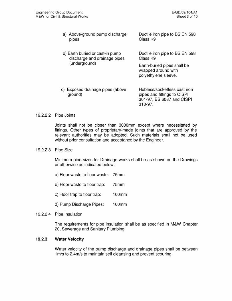
Engineering Group Document E/GD/09/104/A1 M&W for Civil & Structural Works Sheet 3 of 10
a) Above-ground pump discharge pipes
Ductile iron pipe to BS EN 598 Class K9
b) Earth buried or cast-in pump discharge and drainage pipes (underground)
Ductile iron pipe to BS EN 598 Class K9
Earth-buried pipes shall be wrapped around with polyethylene sleeve.
c) Exposed drainage pipes (above ground)
Hubless/socketless cast iron pipes and fittings to CISPI 301-97, BS 6087 and CISPI 310-97.
19.2.2.2 Pipe Joints
Joints shall not be closer than 3000mm except where necessitated by fittings. Other types of proprietary-made joints that are approved by the relevant authorities may be adopted. Such materials shall not be used without prior consultation and acceptance by the Engineer.
19.2.2.3 Pipe Size Minimum pipe sizes for Drainage works shall be as shown on the Drawings
or otherwise as indicated below:-
a) Floor waste to floor waste: 75mm b) Floor waste to floor trap: 75mm c) Floor trap to floor trap: 100mm d) Pump Discharge Pipes: 100mm
19.2.2.4 Pipe Insulation
The requirements for pipe insulation shall be as specified in M&W Chapter 20, Sewerage and Sanitary Plumbing.
19.2.3 Water Velocity
Water velocity of the pump discharge and drainage pipes shall be between 1m/s to 2.4m/s to maintain self cleansing and prevent scouring.

Engineering Group Document E/GD/09/104/A1 M&W for Civil & Structural Works Sheet 4 of 10
19.2.4 Cleaning Eyes and Inspection Openings
The requirements for cleaning eyes and inspection openings shall be as specified in M&W Chapter 20, Sewerage and Sanitary Plumbing.
19.2.5 Pipework Installation The requirements for the installation works shall be as specified in M&W
Chapter 18, Pipework and Pumps. 19.2.6 Cleaning Procedure
The requirements for cleaning shall be as specified in M&W Chapter 21, Water Services.
19.2.7 Testing and Commissioning 19.2.7.1 Drainage pipework shall be tested to BS 5572. 19.2.7.2 All pump discharge pipework shall be hydrostatically tested to at least twice
the anticipated system working pressure. 19.2.8 Drainage Sumps and Covers
The requirements of drainage sumps & covers shall be as specified in M&W Chapter 20, Sewerage and Sanitary Plumbing.
19.3 DRAINAGE WORKS APPLIANCES AND FITTINGS
The requirements for the supply, installation, testing and commissioning of all appliances and fittings shall be as specified in M&W Chapter 20, Sewerage and Sanitary Plumbing.
19.4 SURFACE DRAINAGE WORKS 19.4.1 General
This section specifies the manufacture and installation of all surface storm water Drainage works.
19.4.2 Materials 19.4.2.1 The concrete and steel reinforcement shall be as specified in M&W
Chapter 11, Concrete And Reinforcement. The brickwork shall be as described in the Architectural Specification consisting of common bricks, set and jointed in cement and sand (1:3) gauged with mortar plasticiser.
Engineering Group Document E/GD/09/104/A1 M&W for Civil & Structural Works Sheet 5 of 10
19.4.2.2 Pipes and Fittings shall be as specified in clause 19.2.2 and M&W Chapter 20, Sewerage and Sanitary Plumbing.
19.4.2.3 Conduit pipes for surface water drainage passing under building structures
shall be a minimum of 300mm diameter. 19.4.2.4 Roof drainage installation, workmanship, materials and testing requirements
shall be the same as those described in the Architectural Materials and Workmanship Specification.
19.4.3 Table Drains
Table drains shall be provided at the outer edges of any berms in cuttings or at other locations to the acceptance of the Engineer. Table drains shall be evenly graded throughout their lengths without stepping and shall be flared outwards from the formation. Table drains shall be diverted at intervals so as to discharge storm water into open drains, natural watercourses, culverts or upon the natural ground.
19.4.4 Precast Concrete Drains and Culverts 19.4.4.1 The roadside drains shall be constructed section by section and shall be
generally completed before commencing work on the carriageway and kerbs. The precast units and sections shall be true to shape and of the correct dimensions, finish and strengthened with the required reinforcement.
19.4.4.2 All precast units shall be accepted for use by the Engineer before they are
incorporated into any part of the works. Precast channels, revetment slabs, etc. shall be properly laid and bedded on a sand base at least 75mm thick, unless otherwise stated and joints pointed with cement mortar.
19.4.4.3 Side connections where required or shown on the Drawings shall be
formed and secured in concrete and/or cement mortar and shall be finished to a smooth and uniform appearance.
19.4.4.4 All precast drains and culverts shall be laid to a gradient as indicated on
the Drawings. 19.4.5 Scupper Drains
Scupper drains of 250mm diameter UPVC pipe shall be laid to the correct lines, levels and properly connected to the drop inlet chambers and roadside drains. Each pipe shall be properly bedded down and all butt joints sealed all round with cement mortar filleted up to form a collar 50mm wide by 25mm thick.
Engineering Group Document E/GD/09/104/A1 M&W for Civil & Structural Works Sheet 6 of 10
19.4.6 Subsoil Drains
Unless otherwise stated, subsoil drains shall consist of 19mm size aggregate with a perforated 100mm diameter PVC pipe at its bottom. The whole of the subsoil drain shall be wrapped round with Geotextile Class B membrane as specified in M&W Chapter 4, Earthworks.
19.4.7 Catch Drains and other Open Drains 19.4.7.1 Where the natural ground drains towards cuttings, catch drains shall be
provided at each cutting during each excavation of the adjacent roadway, above each cutting unless otherwise accepted by the Engineer. The edges of catch drains shall not be less than 2.5m from the cutting. Unless otherwise directed by the Engineer, catch basins shall be at least 300mm deep and side slopes not steeper than the batter applicable to the material through which they are cut. The gradient shall be designed to ensure free flow of water and unless otherwise accepted by the Engineer, shall not be less than 1 in 100.
19.4.7.2 Catch drains shall be cut in uniform lines. Where obstructions occur in the
line of a catch drain, the catch drain shall be diverted in a manner that is acceptable to the Engineer. Where graded banks are required in lieu of catch drains, the Contractor shall construct, in the same location, an embankment not less than 450mm high by 300mm wide at the top, with the side slopes not steeper than 2 horizontally to 1 vertically. Material for the embankment shall be obtained either from the excavation work or by neatly and uniformly trimming back the top edge of the batter of the adjacent cutting.
19.4.7.3 At side roads and vehicle entrances, catch drains shall be diverted to the
table drains or other drainage system as accepted by the Engineer. Unless otherwise accepted by the Engineer, longitudinal median drains shall be provided between divided carriageways. Other open drains shall be provided at outlets from catch drains, table drains, subsoil drains, kerb and gutter and other points of water concentration to lead the water clear of the work to points of natural flow into culverts or into pits connected to existing drainage system. As far as practicable, the drains shall follow existing watercourses and depressions in the natural surface.
19.4.8 Lining of Drains Unless otherwise accepted by the Engineer, earth drains, which have a
gradient steeper than 5% shall be lined with concrete. The pitching or lining shall conform to the profile of the drains for a depth of at least 300mm and shall be carried out as specified.
Engineering Group Document E/GD/09/104/A1 M&W for Civil & Structural Works Sheet 7 of 10
19.4.9 Drainage Sumps and Covers 19.4.9.1 The requirements of drainage sumps and covers shall be as specified in
clause 19.2.8.
19.4.9.2 The width of all drainage sumps shall not be less than 1.5 times the diameter of the outgoing drain/pipe.
19.5 CONSTRUCTION Besides the requirements being described in the next section, all
excavation, backfilling, pipeline setting out, concreting works, pipe laying and clearing pipeline of obstruction shall be as specified in M&W Chapter 20, Sewerage and Sanitary Plumbing.
19.6 EXCAVATION 19.6.1 General The Contractor shall notify the Engineer sufficiently in advance of the
beginning of any excavation. The natural ground adjacent to the structure shall not be disturbed without permission of the Engineer.
19.6.2 Depth Trenches or foundation pits for structures shall be excavated to the lines and
levels shown on the plans or as indicated by the Engineer. They shall be of sufficient size to permit the placing of structures at the full width and length shown.
19.6.3 Material Encountered Boulders, logs and any other objectionable material encountered in
excavation shall be removed. 19.6.4 Width of Trench For installations in a trench, the width of the trench shall be sufficient to
permit satisfactory jointing of the pipe and thorough tamping of the bedding material under and around the diameter of the pipe.
19.6.5 Verticality Side walls on trenches shall be practically vertical to an elevation above the
top of the pipe structure.
Engineering Group Document E/GD/09/104/A1 M&W for Civil & Structural Works Sheet 8 of 10
19.6.6 Completion After the excavation is completed, the Contractor shall notify the Engineer to
that effect. No bedding or pipe shall be placed until the Engineer has accepted the excavation and the character of the foundation materials.
19.6.7 Drainage Trenches
Excavation of drainage trenches shall be to the lines and gradients required for the pipes, channels, culverts, etc. The trench bottom shall be of sufficient width to allow adequate working space for the pipe joiners. Unless otherwise specified, excavated material shall not be deposited within 610mm of the edges of the trench. Trenches deeper than 1.5m shall be constructed with suitable temporary ground support. The method and materials for planking and strutting shall be submitted to the Engineer for acceptance. In the event of excavations being made deeper than necessary, they shall be made up with Grade 15 concrete at the Contractor’s expense. The excavation shall be kept free from water by pumping, baling or otherwise.
19.6.8 Subsoil Drain Trenches
Trenches for subsoil drains having pipes up to 150mm diameter shall be excavated to a width of at least four times the nominal diameter of the pipe or as shown on the Drawings. For pipe diameter above 150mm, the width shall be the external diameter of pipe plus 450mm or as shown on the Drawings.
19.7 FOUNDATION 19.7.1 Except for the sections described below, the pipe shall be placed on a firm
earth foundation of uniform density for the entire length of the structure and to the line, levels and camber accepted by the Engineer.
19.7.2 Where rock or other unyielding material is encountered, it shall be removed
to at least 300mm below the bottom of the structure. The width of the excavation shall have a minimum of 600mm greater than the pipe diameter. The excavated area shall be backfilled with selected material and shall be thoroughly compacted to provide a cushion for the structure.
19.7.3 When soft or yielding soil is encountered, the Contractor shall provide a
uniform and adequate support for the pipe by replacing the soil with mechanical compacted granular materials or by providing piled foundation.
Engineering Group Document E/GD/09/104/A1 M&W for Civil & Structural Works Sheet 9 of 10
19.8 BACKFILLING 19.8.1 Material Backfill material shall be selected material to the acceptance of the
Engineer. Backfill material shall preferably be granular. It shall be free of vegetable matter, lumps, cinders, boulders or rocks.
19.8.2 Depositing of Backfill Material The backfill material shall be deposited evenly on both sides of the pipe in
layers not exceeding 150mm in depth (loose measure) and thoroughly compacted to a minimum of 90% of modified AASHTO optimum dry density.
19.8.3 Compaction Compaction may be done by hand or with mechanical equipment, tamping
rollers or vibrating compactors, depending upon field conditions and as accepted by the Engineer.
19.8.4 Minimum Depth The Contractor shall provide a compacted earth cover of at least 600mm or
one diameter, whichever is the greater, over the pipe before equipment is allowed to be driven over it.
19.8.5 Backfilling of Drainage Trenches No trench shall be filled until after the drain therein has been tested and
accepted. Earthfilling from the bottom of trenches and to a height of 300mm above the top of the pipes shall be of selected materials, compacted, watered if necessary and well rammed on either side of the pipes. The remainder of the earthfilling shall be in layers of 300mm each, watered if necessary and well rammed with mechanical rammers or other efficient means of effecting compaction.
19.8.6 Maintaining Shape of Structure 19.8.6.1 Two main movements may occur during backfilling – peaking caused by the
pressure of the compacted side-fill and rolling caused by higher fill or greater compaction on one side.
19.8.6.2 All movements of a point on the circumference of the structure shall be
limited to about 2% of the diameter of the structure. 19.8.6.3 Vertical plumb lines suspended from the crown of the structure on the entire
line shall be used to indicate shape changes or tendency to roll during backfilling and may point to the need for strutting or some modification of the backfilling technique.

Engineering Group Document E/GD/09/104/A1 M&W for Civil & Structural Works Sheet 10 of 10
19.9 TESTING 19.9.1 Test for Pipework Pipework shall be hydrostatically tested to a water head of 1500mm at the
high end and not more than 2400mm at the low end and shall show no appreciable loss of water after elapse of two hours.
19.9.2 Test for Pipeline Pipelines shall be tested in sections so that the above maximum head shall
not be exceeded. Unless otherwise accepted by the Engineer, the test shall commence one hour after filling the test section at which time the level of water at the vertical feed pipe shall be made up to produce the required 1500mm minimum test head. The loss of water over a thirty-minute period shall be measured by adding water at regular ten-minute intervals to maintain the original water level and recording the amounts so added. The drain will pass the test if the volume of water added does not exceed four litres per hour per 6 metres of drain per 50mm of nominal internal diameter. Drains failing to pass the test shall have the defects made good and be re-tested.
19.9.3 Duration In every test, water used shall be left in the pipes until backfilling of trench
filling material to a depth of at least 1 metre over the top of pipes or until permission is given by the Engineer for the water to be released. If pipes become damaged and lose water from any cause and/or admit subsoil water the Contractor shall have the pipes uncovered and the defect made good and the pipes retested as before.
19.9.4 Backfilling Backfilling shall not commence until testing has been conducted to the
acceptance of the Engineer. 19.9.5 Test for Precast Concrete Culverts
The Engineer shall have access to the casting yard where the precast concrete culverts are being manufactured. A copy of the manufacturer’s test certificate shall be provided to the Engineer on demand. The precast concrete pipe culvert shall be tested to SS 183.

Engineering Group Document E/GD/09/104/A1 M&W for Civil & Structural Works Sheet 1 of 11
CHAPTER 20
SEWERAGE AND SANITARY PLUMBING 20.1 GENERAL 20.1.1 General
The works covered under these specifications shall include the design, supply, installation, testing and commissioning of all Sewerage and Sanitary Plumbing works.
20.1.2 Design requirement The Contractor shall perform all design functions necessary for the
development, manufacture/procurement, installation and site testing of systems, sub-systems and components to provide complete and operable installations.
20.1.3 Workmanship Workmanship shall be to the acceptance of the Engineer, who shall have
the right to reject any material he may deem unfit for use or installed in a non-workmanlike manner
20.1.4 Standards, Codes and Regulations 20.1.4.1 The design, manufacture, supply, installation, testing and commissioning of
the Sewerage and Sanitary Plumbing works shall be governed by all applicable latest editions of local codes, regulations, standards and requirements issued by all the local statutory authorities and agencies which shall include the following:
a) Public Utilities Board (PUB) b) Land Transport Authority (LTA) c) Ministry of the Environment (ENV) d) Singapore Productivity and Standards Board (PSB) e) Energy Market Authority (EMA) 20.1.4.2 The Contractor shall apply for all necessary permits required by the relevant
authorities and pay all charges in connection with this work. 20.1.4.3 The whole of the installation shall be carried out by the Contractor's
Licensed Plumber. 20.1.5 Quality Assurance 20.1.5.1 All materials such as pipes, fittings, jointing materials, components and
appliances shall be of the type, size, brand, material, quality and workmanship approved by the ENV/PUB and PSB. Manufacturers of all

Engineering Group Document E/GD/09/104/A1 M&W for Civil & Structural Works Sheet 2 of 11
these products shall have manufactured similar products for a period of at least 5 years.
20.1.5.2 All personnel engaged on welding operations must possess a valid
certificate of competence issued by a relevant authority. 20.1.6 Submissions The Contractor shall submit the following for acceptance by the Engineer.
a) Method statements and QA/QC procedures for site installation works, testing, commissioning and cleaning.
b) Pipe supports and anchor details c) Detailed manufacturer’s drawings, material specifications, catalogues
samples and technical data. d) As-constructed invert levels, gradients, types and size of pipes, levels
at the top of sumps/chambers/manholes and horizontal distances between sumps/chambers/manholes.
20.2 PIPES AND FITTINGS 20.2.1 Materials The materials for the pipes and fittings shall be of the following:
a) Earth buried soil or cast-in vent, soil and waste pipes (underground)
Ductile iron pipe to BS EN 598 Class K9
Earth buried pipes shall be wrapped around with green polyethylene sleeve
b) Exposed soil and waste pipes (above ground)
Hubless/socketless cast iron pipes and fittings to CISPI 301-97, BS 6087 and CISPI 310-97.
c) Exposed main and branch vent pipes (above ground)
Hubless/socketless cast iron pipes and fittings to CISPI 301-97, BS 6087 and CISPI 310-97.
d) Waste pipe discharge from sinks, basins, etc. to floor trap/floor waste
Light gauge copper pipes to BS EN 1057
e) Sewer connection (from last inspection chamber to 1st minor sewer manhole or ENV/PUB manhole)
Vitrified clay pipe and fittings to BS EN 295

Engineering Group Document E/GD/09/104/A1 M&W for Civil & Structural Works Sheet 3 of 11
20.2.2 Pipe Insulation 20.2.2.1 All horizontal waste pipes from floor traps/floor wastes collecting condensate
from the air-conditioning system shall be insulated with 25mm thick fibre glass sectional pipe insulation.
20.2.2.2 The insulation material shall have a density of 80kg/cu m and a maximum
thermal conductivity of 0.03 W/mK at 20 degree C mean temperature. 20.2.2.3 The insulation material shall be sheathed with a vapor barrier of double-
sided aluminum foil with Class `O' flame spread rating in accordance with local fire regulations.
20.2.3 Pipe Joints Joints shall not be closer than 3000mm except where necessitated by
fittings. Other types of proprietary-made joints that are approved by the relevant authorities may be adopted. Such materials shall not be used without prior consultation and acceptance by the Engineer.
20.2.4 Valves Gate valves up to and including 50mm diameter shall be of bronze/brass
type. Gate valves above 50mm diameter shall be of cast/ductile iron type construction with flanged connections.
20.2.5 Pipework Installation The requirements for the installation of works shall be as specified in MW
Chapter 18, Pipework And Pumps. 20.2.6 Cleaning Procedure The requirements for cleaning shall be as specified in MW Chapter 21,
Water Services. 20.2.7 Testing & Commissioning 20.2.7.1 All vent, soil and waste pipework shall be tested to BS 5572. 20.2.7.2 All pump discharge pipework shall be hydrostatically tested to at least twice
the anticipated system working pressure. 20.3 CLEANING EYES AND INSPECTION OPENINGS 20.3.1 Inspection openings and cleaning eyes shall be provided on all soil and
waste pipes so as to provide access for the proper inspection and cleaning of the entire length of the pipe. In all cases where the vertical stack of soil and waste pipe extends 1.2m or more above the ground level, an inspection

Engineering Group Document E/GD/09/104/A1 M&W for Civil & Structural Works Sheet 4 of 11
opening of 200mm(L) x 75mm(W) fitted with a cover fixed to a flange with bolts and nuts, shall be provided near the foot of the stack.
20.3.2 Cleaning eyes shall be provided at all turning points of a pipe. 20.3.3 For pipes cast into walls, cleaning eyes shall be provided at appropriate
intervals and at locations which are accessible at all times. 20.4 SANITARY PLUMBING APPLIANCES AND FITTINGS 20.4.1 Floor Trap Floor traps shall be of cast iron type and complete with circular stainless
steel grating. The traps shall be installed at a level which enables the floor to be graded to the same level and shall be connected to the sanitary plumbing system with an internal min. 100mm diameter outlet complete with inspection eye.
20.4.1.1 Where a riser is provided to a floor trap, it shall be made of light gauge
copper or other accepted piping material.
20.4.1.2 Every floor trap shall have a minimum internal diameter size of 100mm. 20.4.2 Floor Waste 20.4.2.1 The minimum internal diameter of the floor waste shall be 75mm. Only one
sanitary waste appliance may be connected to a floor waste. 20.4.3 Gully Trap 20.4.3.1 All gully traps shall be of heavy duty cast iron type and complete with cast
iron grating. 20.4.3.2 The gully trap riser shall be made of light gauge copper or other accepted
piping material. Where a gully trap is expose to rain water, water tight cover shall be used to prevent rain water ingress to the sewerage system.
20.4.4 Urinal Trap 20.4.4.1 The riser to every urinal trap shall be the same diameter as the opening of
the trap. 20.4.4.2 Each urinal trap shall have an air-tight stainless steel plate cover. 20.4.4.3 Each urinal trap shall have a minimum size of 80mm diameter.
Engineering Group Document E/GD/09/104/A1 M&W for Civil & Structural Works Sheet 5 of 11
20.4.5 Flush Valve 20.4.5.1 All water closets and urinals in public toilets shall be installed with automatic
sensor operated flush valve system (concealed). Automatic flushing shall be sensor operated after every use and after 24 hours since the last flushing.
20.4.5.2 Manual operated flush valve system shall be installed in staff toilets. 20.4.5.3 Flush valves shall be concealed in services shafts with easy access for
maintenance. 20.4.6 Testing 20.4.6.1 In-use tests to the acceptance of the Engineer shall be made to assure
proper functioning of water closets, wash basins, urinals, floor wastes, floor traps and gully traps.
20.4.6.2 Ponding tests for the water tightness at the slab penetrations of water
closets, floor wastes, floor traps and gully traps shall be done and to the acceptance the Engineer.
20.5 BURIED OR CAST IN SEWERAGE AND SANITARY PLUMBING WORKS 20.5.1 Pipework Material Pipework materials for earth-buried or cast in concrete shall be as specified
in clause 20.2.1. 20.5.2 Pipe Laying 20.5.2.1 The pipes shall be laid out separately with the whole length of the barrel of
each pipe on a solid concrete bed. No pipes shall be joined together before being laid out.
20.5.2.2 Sockets shall face up the gradient. The spigot of each pipe shall be driven
home into the socket of the pipe previously laid, the joint completed as specified and the bore of the pipe cleared of any obstruction before the next pipe is laid. Care shall be taken that there is no irregularity in the invert of the joints.
20.5.2.3 The level of each pipe shall be tested by a straight edge laid in the invert of
the pipe previously laid and in the nearest level peg. If the bottom of the trench has been taken too low, it shall be made up with concrete or cement mortar or other granular material, as accepted by the Engineer.
20.5.2.4 Where it is required to shorten any pipe it shall be cut off square and cleanly.
Cast iron and ductile iron pipes shall be cut only with accepted pipe-cutting machines.
Engineering Group Document E/GD/09/104/A1 M&W for Civil & Structural Works Sheet 6 of 11
20.5.2.5 In the event of any pipe being fractured from any cause whatsoever after
having been laid, then the Contractor shall replace such defective pipes to the acceptance of the Engineer.
20.5.2.6 Where laid in hardcore or fill, cast iron and ductile iron pipes subjected to a
superimposed load shall be supported from natural ground level throughout their length by walls and haunching.
20.5.2.7 Where laid in hardcore or fill and not subjected to a superimposed load, or
where laid above ground, cast iron and ductile iron pipes shall be supported on piers behind the socket of each pipe and at intervals of not more than 2700mm.
20.5.2.8 The Contractor shall investigate the soil conditions before laying pipework. In
soft or yielding ground, bakau piles and a bed of reinforced concrete shall be used and the pipework shall be embedded in concrete, to a thickness of at least 150mm all round the pipe.
20.5.2.9 Pipes of 300mm/225mm diameter where shown, laid through or under walls,
shall be protected by means of brick ring arches, lintels or sleeves in such a manner that the weight of the wall shall not bear on the pipes.
20.5.3 Pipeline Setting Out 20.5.3.1 Excavation for trenches shall be to straight lines and the gradients required
for the pipes and beds as specified. The trench bottom shall be of sufficient width to allow adequate working space for pipe layers and jointers but beyond these requirements, the width must be kept to a minimum.
20.5.3.2 Before any work commences, the pipe trench shall be set out. The
inspection chamber centres shall be marked by a centre peg whose location shall be tied to 3 pegs situated outside the working area.
20.5.3.3 Sight rails shall be set up painted black and white to mark the centre line of
the pipe-lines, and boning rods shall be used to give the distance from the sight rails to the invert of the pipe-lines. It is desirable that no fewer than 3 site rails be set up on each line so that if one is disturbed it would be obvious. The maximum distance between sight rails should be 25 metres.
20.5.3.4 For the lengths of the pipe-lines which are curved in plan or in elevation, the
curve shall be obtained by deflecting the pipes at each joint. No work shall be carried out by the Contractor until the detailed proposals are accepted by the Engineer
20.5.3.5 Strongly constructed, clearly painted boning rods shall be provided at each
length where work is in progress. Such boning rods shall be designed to show the pipeline invert level below the sight rails.
Engineering Group Document E/GD/09/104/A1 M&W for Civil & Structural Works Sheet 7 of 11
20.5.3.6 When excavation is completed and before any further work commences,
wooden pegs are to be driven into the formation at not more than a metre centres the level of each peg being adjusted to the proposed pipe-lines invert by the use of the sight rails and boning rods.
20.5.3.7 Before any permanent work may commence, the Engineer shall be invited to
check the setting out. 20.5.4 Excavation 20.5.4.1 All excavation shall be carried out to the required lengths, width, depths,
inclinations and curvatures as may be necessary for the construction of the Works.
20.5.4.2 Excavation for pipe trenches shall not be less than 600mm wider than the
internal diameter of the pipes and the ground under beds shall be carefully graded. Proper shoring, planking, strutting, or sheet piling strutting shall be constructed and maintained to ensure the trench does not collapse.
20.5.4.3 When excavating trenches in carriageways, the granite blocks, crusher-run
granite, precast concrete units and bricks, etc. that have already been laid or constructed shall be removed by the Contractor, stacked aside and kept separate from the general trench excavated material for re-use in reinstatement. The Contractor is fully responsible for the reinstatement of all existing and/or constructed ground surfaces.
20.5.4.4 Surplus excavation soil shall be removed from the site. 20.5.4.5 Allowance shall be made for removing all rock met with in the course of
excavation with picks wedges, levers, sledge hammers and compressor drills. No blasting shall be allowed without written permission from the Engineer
20.5.4.6 All excavation shall be kept free from water at all times by pumping or
temporary drainage. 20.5.4.7 Where localised areas of soft material at the invert of the excavation are
required to be removed by the Engineer, backfilling of the resultant void shall be carried out using lean concrete.
20.5.4.8 The Contractor shall be completely responsible for the safety of all
excavations, trenches, pits, etc. from collapse and for the safety of any surrounding structures, which may become endangered by the Works. He shall ensure that all necessary safety measures are taken during any excavations.
20.5.4.9 In the event that the standard of timbering or the securing of the sides of the
excavation is not to the Engineer’s satisfaction he may, one hour after notifying the Contractor or his representative, employ another Contractor to
Engineering Group Document E/GD/09/104/A1 M&W for Civil & Structural Works Sheet 8 of 11
alter, strengthen or reconstruct the timbering and the cost of such labour, transport and materials employed shall be paid for by the Contractor.
20.5.4.10 Should the Contractor’s temporary Works fail, regardless of acceptance by
the Engineer, the Contractor shall take full responsibility for the damage and repair to his works and to any adjacent works belonging to him or any other party.
20.5.4.11 The Engineer shall have the right to order excavation and construction work
to be carried out in such lengths and in such sections of the Works as will in his opinion, minimise the danger of such open excavations affecting the stability of any nearby structures or ground. The Contractor shall have no claim for any extra payment on this account.
20.5.4.12 Trenches shall be left open for the inspection of the Engineer and the local
authority's inspector and shall not be covered up until the drains have been properly tested and approved by the ENV/PUB and accepted by the Engineer.
20.5.5 Back Filling 20.5.5.1 All concrete shall be thoroughly set before backfilling commences. In
backfilling the excavation, only selected hard dry material free from lumps exceeding 75mm in size and free from stones shall be used in the initial backfilling and shall be carefully placed next to the permanent work and well packed and well rammed in layers of 150mm. The remainder of the excavations shall be filled in with the best and most suitable portions of the excavated material, in layers of not more than 300mm deep each layer shall be thoroughly rammed before the next layer is placed. Surplus spoil shall be piled on top of the filling to the extent of possible subsidence. The Contractor shall maintain all refilled trenches to the acceptance of the Engineer
20.5.5.2 If insufficient suitable material is available from the excavations then the
Contractor shall supply, deliver and unload accepted fill material on site for such backfilling.
20.5.6 Concreting Works 20.5.6.1 The components of the reinforced concrete shall be as specified in MW
Chapter 11, Concrete and Reinforcement. 20.5.6.2 Concrete beds shall be 150mm thick and shall have at least 150mm width at
each side of the external diameter of the pipe barrels when laid. Unless otherwise specified, the concrete shall be Grade 25.
20.5.6.3 For pipes to be haunched, the concrete shall be carried up for the full width
of the bed to the level of the horizontal axis of the pipe and shall then be splayed from this level and carried upwards to meet the pipe barrel tangentially at the soffit.
Engineering Group Document E/GD/09/104/A1 M&W for Civil & Structural Works Sheet 9 of 11
20.5.6.4 All drainlines passing under buildings and driveways are to be surrounded
with concrete, which shall be carried up, from the bed in a square section with a minimum of 150mm thickness over the barrel of the pipes.
20.5.6.5 Traps and gullies shall be properly bedded on and surround with concrete. 20.5.7 Tests 20.5.7.1 Pipework shall be hydrostatically tested to a water head of 1200mm at the
high end and not more than 2400mm at the low end and shall show no appreciable loss of water after elapse of two hours.
20.5.7.2 Pipelines shall be tested in sections so that the above maximum head shall
not be exceeded. Unless otherwise accepted by the Engineer, the test shall commence one hour after filling the test section at which time the level of water at the vertical feed pipe shall be made up to produce the required 1500mm minimum test head. The loss of water over a thirty-minute period shall be measured by adding water at regular ten-minute intervals to maintain the original water level and recording the amounts so added. The drain shall pass the test if the volume of water added does not exceed four litres per hour per 6 metres of drain per 50 mm of nominal internal diameter. Drains failing to pass the test shall have the defects made good and shall be re-tested.
20.5.7.3 In every test, water used shall be left in the pipes until they are covered with
earth or other trench filling material to a depth of at least 1000mm over the top of pipes and until permission is given by the Engineer for the water to be released. If after the Engineer has given permission for the trenches to be refilled and pipes become damaged and lose water from any cause and/or admit subsoil water the Contractor shall have the pipes uncovered and the defect made good and the pipes retested as before.
20.5.7.4 Backfilling shall not commence until testing has been conducted to the
acceptance of the Engineer 20.5.8 Clearing Pipeline of Obstruction The interior of the pipe-lines shall be inspected to ascertain that the pipes
are entirely clear of obstructions and that invert is smooth. In the case of pipes which cannot be inspected from the inside, generally those under 1200mm in diameter, a loose plug in the form of cylinder with solid ends made of timber not less than 25mm in thickness or of any other approved material shall be made to pass through each pipe-line. The outside diameter of the ends of the plug shall not be smaller than 25mm less than the diameter of the pipe thorough which it is to be passed and its length shall not be less than its diameter.
Engineering Group Document E/GD/09/104/A1 M&W for Civil & Structural Works Sheet 10 of 11
20.6 INSPECTION CHAMBERS AND WASTE SUMPS COVERS 20.6.1 Inspection chambers/waste sumps shall be of concrete construction. They
shall have minimum internal dimensions of 900mm in length and 700mm in width. The size shall be increased accordingly depending on the number of branch drains to be connected and the depth of such inspection chambers.
20.6.2 In cases where the inspection chamber/waste sump cannot be constructed
in concrete due to the site conditions, it shall be constructed in brick. It shall be 225mm thick, constructed in English bond in cement mortar beds and the vertical joints shall be completely filled with mortar as the bricks are laid. Joints shall be flush pointed as the work proceeds.
20.6.3 Inspection chambers/waste sumps shall be rendered internally and
externally with cement and sand (1:3) in two coats to a total thickness of 16mm, trowelled smooth. On firm ground, the inspection chamber/waste sump shall be constructed on a reinforced concrete base at least 150mm thick and such base shall extend at least 150mm beyond the external walls of the inspection chambers.
20.6.4 On soft or yielding ground, the inspection chamber/waste sump shall be
constructed on 'bakau' piles and a base of reinforced concrete, or tanalised piles to the Contractor’s Professional Engineer’s design and to the acceptance of the Engineer and relevant authority.
20.6.5 The depth of the main channels shall be not less than the diameter of the outgoing pipe. Main channel inverts for pipes up to and including 225mm diameter shall be vitrified clay channels. Main channel inverts for pipes over 225mm diameter shall be formed in concrete trowelled smooth.
20.6.6 The internal dimensions of every inspection chamber/waste sump shall not
exceed 1350mm in length and 1350mm in width. Where the dimensions exceed 1350mm, an additional inspection chamber shall be provided without any cost addition to the Contract. If this is the case, the Contractor shall immediately bring it to the Engineer’s attention.
20.6.7 Branch bends up to and including 150mm diameter shall be vitrified clay to
3/4 section curved in the direction of flow and set to deliver over the main channel invert. Branch bends over 150mm diameter shall be curved in the direction of flow and shall be formed in concrete trowelled smooth.
20.6.8 Spaces between branch bends shall be completely filled with concrete and
the faces above the main and branch channel inverts shall be trowelled smooth. Benching shall all be formed in concrete trowelled smooth and shall open towards the main channel at a slope of 1 in 6.
20.6.9 Pipes passing through inspection chamber/waste sump walls shall be solidly
built in and the walls made watertight throughout.
Engineering Group Document E/GD/09/104/A1 M&W for Civil & Structural Works Sheet 11 of 11
20.6.10 Inspection chambers/waste sumps shall be roofed over with a reinforced
concrete slab not less than 150mm thick and provided with an opening fitted with an air-tight frame and cover. Screw down covers with stainless steel bolts shall be used within underground structures (underpass, basements, MRT stations etc.).
20.6.11 Except for screw down covers used within underground structures
(underpass, basements, MRT stations etc. which is not maintained by ENV/PUB), all covers and frames shall be of the types approved by the Sewerage Department and conform to SS 30:1999. All frames shall be solidly bedded in cement mortar so that the covers when in position are fair and even with the adjacent surfaces. Heavy duty cast iron frames and covers shall be used in every driveway and carpark or in area subject to heavy loading. Medium duty covers shall be used in all other external inspection chamber/waste sumps etc.
20.6.12 Recessed pattern covers shall be provided and filled and surfaced with
materials to match surrounds. Frames of light duty covers shall be set with covers in position to avoid distortion of frames.
20.6.13 Three sets of lifting keys for each type of cover shall be provided by the
Contractor to the Engineer. 20.6.14 Step irons shall conform to BS 1247. Round bar corner pattern step irons
shall be used in brick inspection chambers and shall be built in at 300mm vertical interval. Step irons shall be used in precast concrete sections and unless otherwise directed they shall be provided and fixed in the concrete inspection chamber components by the component manufacturer before delivery, in accordance with BS 5911.

Engineering Group Document E/GD/09/104/A1 M&W for Civil & Structural Works Sheet 1 of 8
CHAPTER 21
WATER SERVICES 21.1 GENERAL 21.1.1 General The works covered under these specifications shall include the design,
supply, installation, testing and commissioning of Water Services works. 21.1.2 Design Requirement The Contractor shall perform all design functions necessary for the
development, manufacture/procurement, installation and site testing of systems, sub-systems and components to provide complete and operable installations.
21.1.3 Workmanship Workmanship shall be to the acceptance of the Engineer, who shall have
the right to reject any material he may deem unfit for use or installed in a non-workmanlike manner.
21.1.4 Standards, Codes and Regulations 21.1.4.1 The design, manufacture, supply, installation, testing and commissioning of
the water supply services shall be governed by all applicable local codes, regulations, standards and requirements issued by all the local statutory authorities and agencies which shall include the following:-
a) Fire Safety & Shelter Department (FSSD) b) Public Utilities Board (PUB) c) Land Transport Authority (LTA) d) Ministry of the Environment (ENV) e) Singapore Productivity and Standards Board (PSB) f) Energy Market Authority 21.1.4.2 The Contractor shall apply for all necessary permits required by the relevant
authorities and pay all charges in association with this work. 21.1.4.3 The whole of the installation shall be carried out by the Contractor's
Licensed Plumber.

Engineering Group Document E/GD/09/104/A1 M&W for Civil & Structural Works Sheet 2 of 8
21.1.5 Quality Assurance 21.1.5.1 All materials such as pipes, fittings, jointing materials, components and
appliances shall be of the type, size, brand, material, quality and workmanship approved by the PUB, ENV and PSB. Manufacturers of all these products shall have manufactured similar products for a period of at least 5 years.
21.1.5.2 All personnel engaged on welding operations must possess a certificate of
competence issued by a relevant authority. 21.1.6 Submissions The Contractor shall submit the following for acceptance by the Engineer.
a) Method statements and QA/QC procedures for site installation works, testing, commissioning, cleaning and sterilization.
b) Pipe supports and anchor details c) Design calculations, structural details and shop drawings of the tank
supports d) Dimensioned tank openings locations, levels, pipeworks and
installation details e) Detailed manufacturer’s drawings, material specifications, catalogues,
samples and technical data. 21.2 PIPES AND FITTINGS 21.2.1 Pipework Materials The materials for the pipes and fittings be of the following:
a) Underground distribution pipe: (i) For pipe 80mm diameter and above, ductile iron pipes with
cement lining to BS EN 545 class K9 (ii) For pipe 76mm diameter and below, heavy gauge copper tube to
BS EN 1057 b) Aboveground distribution pipe: (i) For pipe 80mm diameter and above, ductile iron pipes with
cement lining to BS EN 545 class K9 (ii) For pipe 76mm diameter and below, light gauge copper tube to
BS EN 1057. c) Overflow pipe and tank drainage pipe for all storage tanks:
Ductile iron pipes with cement lining to BS EN 545 class K9
Engineering Group Document E/GD/09/104/A1 M&W for Civil & Structural Works Sheet 3 of 8
21.2.2 Pipe Joints Joints shall not be closer than 3000mm except where necessitated by
fittings. Other types of proprietary-made joints that are approved by the relevant authorities may be adopted. Such materials shall not be used without prior consultation and acceptance by the Engineer.
21.3 VALVES 21.3.1 General a) All drain cocks, bib taps, constant flow regulators, stop cocks, gate
valves, flush valves shall be of a dezincification resistant type. b) Isolating valves shall be fitted to all items of plant including tanks,
pumps, etc. c) Regulating valves shall be of globe type for fitting on branch lines, by
passes, etc., where regulation of flow is required for balancing the systems.
d) All valves shall be of heavy duty suitable for the working hydraulic
pressure of up to 1000kPa. e) All valves shall be installed with the valve stems fully vertical or
horizontal. All valves shall be arranged so that clockwise rotation of the spindle closes the valve. Where installed at a change in direction of the pipework, angle valves are preferred to straight through valves and bends.
f) Valves shall be furnished and installed for the proper isolation, function
and operation of the system and equipment. g) All valves for a particular function shall be of one manufacture in order
to achieve ease of maintenance. h) Valves shall be fitted in accessible positions to facilitate easy operation
and maintenance. The connection between each valve and the adjacent equipment shall be made either with a union or flange for ease of dismantling.
21.3.2 Isolating Valves Isolating valves up to 65mm diameter shall be of copper alloy construction
with female screwed connections. Isolating valves of 80mm diameter and above shall be of cast/ductile iron gate type construction with flanged connections.
Engineering Group Document E/GD/09/104/A1 M&W for Civil & Structural Works Sheet 4 of 8
21.3.3 Regulating Valves Regulating valves up to 50mm diameter shall be of the bronze globe type
with female screwed connections. Regulating valves of 65mm diameter and above shall be of ductile/cast iron globe type with flanged connections.
21.3.4 Check Valves Check valves up to 50mm diameter shall be of the bronze swing check type
with female screwed connections. Check valves of 65mm diameter and above shall be of the spring loaded non-slamming type and ductile/cast iron construction with flanged connections.
21.3.5 Strainers a) Strainers shall be installed on all systems and equipment susceptible
to damage from dirt, grit or foreign matter including, but not limited to, pumps and control valves.
b) Strainers shall be of "Y" pattern. Strainers up to 40mm diameter shall
be of gunmetal construction. Strainers of 50mm diameter size and above shall be of cast iron construction.
c) Each strainer shall be complete with replaceable screen and having a
size and area liberally sized to offer minimum resistance to flow. d) Screens for installation and service in water systems shall be to ASTM
127 standard or equivalent with a mesh size not greater than 56 mesh. e) Strainers shall have screwed inlet and outlet connections for up to
40mm diameter and flanged connections for 50mm diameter and above. Strainers of 100mm diameter and over shall be fitted with 12mm diameter drain valve to facilitate cleaning.
21.3.6 Pressure Relief Valves a) Each pressure relief valve shall be of the fully enclosed type and fitted
with hand easing gear and shall comply with AS 1271. b) Each pressure relief valve in a pressure reducing station shall have a
flow capacity equal to that of the pressure reducing valve. c) Pressure relief valves in locations other than pressure reducing
stations shall have flow capacities equal to that of the associated equipment.

Engineering Group Document E/GD/09/104/A1 M&W for Civil & Structural Works Sheet 5 of 8
21.3.7 Automatic Air Vent Automatic air vent of accepted manufacture shall be provided at all high
points and the top of each pipe riser where venting are required. 21.3.8 Pressure Gauge a) Pressure gauges shall conform to AS180 - "Bourdon tube pressure
and vacuum gauges". b) The maximum scale value of the gauge shall be about 150% of the
anticipated maximum operating pressure. c) Pressure gauge shall be easily removed without interruption after
installation. d) A stainless steel pulsation snubber shall be used in conjunction with
the pressure gauge if necessary. e) In addition to pressure gauge locations, gunmetal test valve of 10mm
or 15mm size shall be fitted on suction and delivery pipes or testing pumps.
21.3.9 Flexible Connector a) Flexible connectors shall be provided to prevent transmission of
vibration from all rotating equipment. b) Flexible connectors shall be used for piping passing through building
movement joints. c) Flexible connectors shall be located as close to the rotating equipment
as practical and shall be parallel to each other and the rotating shaft centre line. Flexible connectors shall be selected to accommodate the axial and lateral dynamic deflections of the equipment to be isolated and to accommodate building movement/settlement.
d) Care shall be taken to restrain longitudinal thrust due to internal
pressure in the flexible connections. Piping shall be anchored on the side of the flexible connections remote from the rotating equipment.
e) The manufacturer's recommendations for the installation of flexible
connectors shall be strictly observed.

Engineering Group Document E/GD/09/104/A1 M&W for Civil & Structural Works Sheet 6 of 8
21.3.10 Gasket a) Gaskets shall be suitable for temperature, service and pressure of the
system, installed in accordance with manufacturer's recommendations. Make-up flanged joints with one-piece ring gaskets, 1.5mm thick, neoprene rubber shall be used.
b) Where there are flanged joints between dissimilar metals, insulating
gaskets, sleeves and washers shall be installed between flanges, bolts and nuts respectively.
21.3.11 Ball Float Valve a) Ball float valve shall be of copper alloy construction. The closing of the
valve shall be of slow motion design and shall have a "close and lock" action so that the valve can only be opened when the water drops to a designed level.
b) Each ball float shall be of copper with seam welding all around. c) Each connection shall be of flange joint for size 80mm diameter and
above, or screw joint for 65mm diameter and below. 21.4 INSTALLATION The requirements for the installation works shall be as specified in MW
Chapter 18, Pipework and Pumps. 21.5 CLEANING PROCEDURE a) The Contractor shall exercise every precaution to avoid introducing
foreign matter such as welding beads and slag or dirt into piping system. The Contractor shall hammer completed welds to loosen debris. All piping, valves and fittings shall be internally cleaned of oil, grease or dirt, prior to assemble into system, by use of wire brush and swab.
b) Following fabrication and erection, the Contractor shall clean all piping
of 150mm diameter and smaller by flushing with clean water and run to waste until thoroughly free of all dirt, oil and cuttings, etc. Generally, each size of pipe shall be flushed separately before being joined with larger size piping.
c) The Contractor shall clean piping of 200mm diameter and larger by
pulling through steel brush for entire length of each pipe size, followed by fibre brush or swab, brushes and swabs slightly larger than inside diameter of pipe being cleaned.

Engineering Group Document E/GD/09/104/A1 M&W for Civil & Structural Works Sheet 7 of 8
d) All cleaning operations shall be continuous throughout the piping system, except at joints that are required for the final joining of various sections of the cleaned piping. After cleaning and until the above stated joints are made, the ends of sections of piping shall be adequately and tightly sealed off to prevent any dirt, water or other foreign matter from entering the ends of the pipes.
e) Before submitting piping systems for acceptance, all strainers shall be
inspected and thoroughly cleaned. Temporary strainers shall be provided where required for cleaning and flushing operations.
21.6 TESTING AND COMMISSIONING 21.6.1 All pipework shall be hydrostatically tested to at least twice the anticipated
system working pressure. 21.6.2 All joints shall be left exposed for inspection during testing. 21.6.3 The hydrostatic test pressure shall be measured at the lowest point of the
installation or section being tested and shall be held for a period of not less than 24 hours. The test pressure shall not be observed to reduce by more than 5% and there shall not be any leakage.
21.6.4 Underground water mains shall be tested both before and after backfilling. 21.7 WATER STORAGE TANK 21.7.1 General The Contractor shall supply, install and test all water storage tanks of the
specified capacities complete with all necessary accessories, steel RSJ supports and concrete footings.
21.7.2 Tank Construction 21.7.2.1 All tanks shall be divided into two compartments with interconnecting
pipework to allow for any one of the compartments to be closed down for maintenance without affecting the service.
21.7.2.2 Each tank compartment shall be provided with the following:
a) Access opening of minimum 600mm diameter or 600mm by 600mm. b) Flanged connections for water inlet, drain-off, wash-out and overflow
pipework. All overflow pipes are to be screened. c) Isolating valves shall be provided at all make-up, drain-off and wash-
out points.
Engineering Group Document E/GD/09/104/A1 M&W for Civil & Structural Works Sheet 8 of 8
d) Water level indicator, air vent pipe ends and drain pipe ends shall be provided with mosquitoes proof netting.
e) A stainless steel ladder to the acceptance of the Engineer shall be
provided inside and outside of each compartment. Size of ladders shall be 350mm wide with 50mm x 10mm stiles.
f) Water level sensors and controllers. 21.7.3 Tank Installation 21.7.3.1 Each tank shall be installed on the supporting RSJ and reinforced concrete
piers with a layer of neoprene pad in between. 21.7.3.2 The usage of the water tank, operating levels (e.g., top, low and overflow
water levels) and the tank effective capacities shall be clearly printed onto the side of each tank at conspicuous position.
21.7.3.3 All steel RSJs shall be galvanized as specified in MW Chapter 12, Structural
Steelwork and Architectural Specification. 21.7.4 Tests 21.7.4.1 All water tanks shall be filled up for testing of water tightness after erection
and shall show no signs of leakage over a continuous test period of 96 hours.
21.7.4.2 Sides and edges of sectional tanks shall be checked for any distortion. 21.8 WATER SERVICES PUMPS
All Water Services pumps shall have a speed of 2900rpm (unless otherwise specified by the Engineer). All other requirements shall be as specified in MW Chapter 18, Pipework and Pumps.

Engineering Group Document E/GD/09/104/A1 M&W for Civil & Structural Works Sheet 1 of 30
CHAPTER 23
ELECTRICAL WORKS
23.1 GENERAL REQUIREMENT 23.1.1 General The works covered under these specifications shall include the design,
supply, installation, testing and commissioning of all electrical equipment and materials required for the drainage, sanitary and water pumping systems and temporary electrical works associated with the civil works.
23.1.2 Workmanship
Workmanship shall be to the acceptance of the Engineer, who shall have the right to reject any material he may deem unfit for use or installed in a non-workmanlike manner.
23.1.3 Design requirement The Contractor shall perform all design functions necessary for the
development, manufacture/procurement, installation and site testing of systems, sub-systems and components to provide complete and operable installations.
23.2 STANDARDS, CODES AND REGULATIONS 23.2.1 The design, manufacture, supply, installation, testing and commissioning of
the Electrical works shall be governed by all applicable latest editions of local codes, regulations, standards and requirements issued by all the local statutory authorities and agencies which shall include the following:
a) Public Utilities Board (PUB) b) Land Transport Authority (LTA) c) Singapore Productivity and Standards Board (PSB) d) Energy Market Authority (EMA) e) EN 50122-1: Part 1 f) EN 50122-2: Part 2 23.2.2 All equipment and accessories specified and used shall conform to the
relevant Singapore Standards, British Standards or acceptable technical equivalent standards of the Country of Origin.
23.2.3 All electrical works shall be carried out by workers licensed under the
Electrical Workers and Contractors Licensing Act.
Engineering Group Document E/GD/09/104/A1 M&W for Civil & Structural Works Sheet 2 of 30
23.3 SYSTEM SPECIFICATION 23.3.1 The equipment supplied shall be suitable for operation with the following
power supply rating, as appropriate: 230V, 1 phase, 50Hz 400V, 3 phase, 50Hz
Voltage variation tolerance ± 10 % Control and indication 50V maximum, 2 wire d.c. or a.c., preferred voltages
are 24V and 48V. Control circuits shall be designed, arranged and protected to limit dangers resulting from a fault between the control circuit and other conductive parts liable to cause malfunction (e.g. inadvertent operation) of the controlled equipment.
23.3.2 The power and control cables shall be segregated and run in separate cable
trays / trunkings / conduits. 23.4 SUBMISSIONS The Contractor shall submit the following for the acceptance by the
Engineer prior to fabrication and installation.
a) Detailed construction, single line diagrams and control circuit diagrams for all motor control panels
b) Material samples c) Method statements and QA/QC procedures for installation, testing and
commissioning. 23.5 LV CABLES AND CONDUCTORS 23.5.1 All cables shall be rated at 600/1000V grade. 23.5.2 All cables shall be installed in conduits, trunking and trays as appropriate.
Armoured cables shall be used for the circuits in tunnels. 23.5.3 All cables drawn into conduit systems or laid in trunking shall be PVC
insulated conforming to SS 358:1998 or approved equivalent. 23.5.4 The minimum size of cables shall be as follows unless otherwise
specified:
Lighting: 2.5 sq. mm Small Power: 2.5 sq. mm Control: 1.5 sq. mm
Engineering Group Document E/GD/09/104/A1 M&W for Civil & Structural Works Sheet 3 of 30
23.5.5 Cables shall be as follows:
i) All essential circuit cabling for underground stations shall be of the
fire resistant, low smoke zero halogen (LSOH) and anti-termite type. ii) All normal circuit cabling for underground stations shall be of the
flame retardant, low smoke zero halogen (LSOH) and anti-termite type.
iii) All essential circuit cabling for tunnel shall be of the fire resistant, low
smoke zero halogen (LSOH) and anti-termite type with armouring for mechanical protection.
iv) All normal circuit cabling for tunnels shall be of the flame retardant,
low smoke zero halogen (LSOH) and anti-termite type with armouring for mechanical protection.
23.5.6 Fire resistant, low smoke, halogen free materials shall meet the following
requirements: (i) IEC 61034 and BS EN 50268-2: 3 metre Cube Smoke Obstruction
Test. (ii) IEC 60331 Fire Resisting Characteristics of Electric Cables. (iii) Limiting Oxygen Index of at least 30, to ASTM D-2863. (iv) A temperature index (TI) of 260ºC to ASTM D-2863. (v) All insulation is to be moisture and heat resistant, with temperature
ratings appropriate to the application conditions and in no case lower than 90ºC (194ºF).
(vi) When a sample of cable is subjected to the combustion test for the
determination of the amount of halogen acid gases (other than hydrofluoric acid) as set out in IEC 60754 - Part 1, and the amount of halogen acid evolved is less than 0.5%, the cable shall be regarded as halogen free.
23.5.7 Flame retardant, low smoke halogen free materials shall meet the
requirements of clause 23.5.6 (i), (ii), (iii), (iv), (v) and in-addition of the following:
(i) IEC 60332 Parts 1 & 3, BS EN50265-1 (Common test methods for
cables under fire conditions. Test for resistance to vertical flame propagation and for a single insulated conductor or cable. Apparatus) and BS EN 50265-2 (procedure 1 KW pre-mixed flame), tests on single and bunched cables under fire conditions.
Engineering Group Document E/GD/09/104/A1 M&W for Civil & Structural Works Sheet 4 of 30
23.5.8 The above requirements shall be met without compromising the anti-termite, mechanical and electrical properties of the cables, both during and after installation, to meet the other requirements of the specification.
23.5.9 The oversheath for the cables shall be an extruded layer of fire retardant
elastomer, coloured in black or other colours accepted by the Engineer. 23.5.10 Armoured multi-core cables shall be single wire armoured with galvanised
steel wires of a nominal diameter of not less than 1.60mm complying with BS EN 10257-1. Aluminium armour shall be used for single core cables.
23.5.11 Compression glands shall comply with BS 6121 and shall be designed for
the termination and clamping of armoured wires and shall be fitted with an earth bond terminal attachment. The armour for cables shall not be used as earth conductor.
23.5.12 Jointing and terminating accessories shall include all necessary internal
and external fittings and insulating materials. They shall also include precisely dimensioned cable stripping ferrules and the mechanical gland designs. It shall be possible to erect and dismantle compression glands without the use of special tools.
23.5.13 All cables entering or leaving equipment shall be provided with separate
terminations and be spaced so that any one cable out of a number of such cables can be removed without disturbing the remainder.
23.5.14 All cables installation shall be continuous and without joints unless
otherwise accepted by the Engineer. The cables shall also be installed neatly and truly vertical, horizontal or parallel with the features of the building.
23.6 CABLE TRAYS, CONDUITS AND TRUNKING 23.6.1 General
a) Cable trays shall be perforated and manufactured from cold rolled steel.
b) All fixings and supports shall be at regular interval not exceeding
1200mm and 150mm from all bends, tees, intersections and risers. c) Manufacturer's standard fittings shall be used for bends, angles, tees,
intersections, and other non-standard runs. d) Conduits, trays, trunking and accessories shall be electrically and
mechanically continuous throughout their length and be effectively bonded to the earthing system.
Engineering Group Document E/GD/09/104/A1 M&W for Civil & Structural Works Sheet 5 of 30
e) Whenever cable trays or trunking pass through fire wall or floor, the
Contractor shall be responsible for sealing the gaps between wall and cable tray or trunking with sealing material having the same fire-rating as the fire wall or floor.
23.6.2 Conduits
a) Conduits shall be of heavy gauge, screwed and hot dip galvanised to
comply with SS 504 - "Rigid steel conduits for electrical installation" or BS 4568 Class 4. Flexible conduits to comply with BS 731-1.
b) All conduits shall be free from burrs and internal roughness. The screw
connections shall be made in such a manner as to ensure good electrical and mechanical conductivity throughout when assembled and be earthed with heavy copper wiring. All conduits not cast in concrete shall be securely fixed by means of hot dip galvanised saddles at not more than 1.0m centres for 20mm conduits and 1.2m centres for larger diameter conduits.
c) All conduit fittings shall be hot-dip galvanised or of corrosion resisting
materials. d) Conduit terminations at switches, distribution boards etc. shall be
made with coupler and male brass bushes. e) Connections to motors and other equipment subject to vibration shall
be made with a length of heavy duty water-tight metallic flexible tube set into suitable screwed conduit adaptors. The metal frame or other parts of the equipment so connected shall be earthed to the conduit system independently of the flexible tube.
f) All conduits chased in walls shall be covered with a full thickness of
plaster. g) Unless otherwise specified or accepted by the Engineer, all conduits
below ceiling line shall be concealed in walls, partitions or floor. h) No cable shall be drawn into the conduit system until all conduits
including the draw-in boxes have been fixed in place. i) No joints shall be allowed for cables installed in conduit. j) No conduit shall be less than 20mm diameter. k) Installation of conduit shall not obstruct equipment and shall be neatly
and truly vertical, horizontal or parallel with the features of the building. l) On completion of installation of each conduit, all exposed terminations
shall be plugged effectively against the ingress of water and dirt.
Engineering Group Document E/GD/09/104/A1 M&W for Civil & Structural Works Sheet 6 of 30
23.6.3 Trunking
a) Cable trunking to SS 249 shall be of heavy gauge zinc coated mild
steel sheets finished with powder epoxy coating. b) Trunking shall be fitted with removable zinc-coated mild steel lids
extending over their entire lengths. c) The thickness of the trunking shall be 1.2mm for sizes up to 100mm x
100mm, 1.5mm for sizes up to 150mm x 150mm, and 2.0mm for larger sizes.
d) Trunking shall be supported by hot dip galvanised steel brackets
securely fastened to walls by means of plugs and brass screws. e) Trunking shall be run neatly on the surface of the building and truly
vertical, horizontal or parallel with the features of the building and at least 150mm clear of mechanical services.
f) Connection between trunking and equipment shall be by a screwed
coupler and bush or a standard flanged coupling or and adapter neck, fabricated or cast. Direct attachment of trunking to equipment will only be permitted if cable entries are provided with smooth bore bushes or grommets and the return edge of the trunking is left intact.
23.6.4 Cable Trays
a) Cable trays shall be perforated and manufactured to BS 1449: Part 1
and accessories to BS EN ISO 1461. They shall not be less than 1.5mm thick.
b) Cables shall be installed on tray in a single layer firmly secured by
saddles and straps spaced at regular interval. c) Cable trays shall have an up turned flange both sides of 20mm deep
and complete with standard radius bends, etc. and fixing brackets fabricated from hot dip galvanised steel angle, channels etc.
d) Trays shall be supported at not more than 1 metre intervals by hot-
dipped galvanised steel brackets. e) Cable trays shall be cut along a line of plain metal and not through
perforations and treated with cold galvanising paint. Sharp edges shall be removed prior to the installation.
Engineering Group Document E/GD/09/104/A1 M&W for Civil & Structural Works Sheet 7 of 30
23.7 EARTHING 23.7.1 All metal parts including conduits, trays, trunking and equipment shall be
properly earthed in accordance with the latest edition of the SS CP 5. There shall be no discontinuity of earthing should any of these parts be dismantled.
23.7.2 MCPs in the tunnels shall be insulated from tunnel structure. 23.8 BALANCE OF LOAD The Contractor shall balance the electrical load as far as possible between
the individual phases of supply. 23.9 MOTORS 23.9.1 All varnishes and impregnate used shall be inorganic and suitable for
tropical service. Bearings shall be so selected for its duty and shall be housed in a dust tight enclosure with efficient shaft seals to prevent dust ingress and escape of grease, and be equipped with grease nipples and relief plugs. Terminal boxes shall be of cast iron and be provided with glands drilled and taped to accept conduits. Terminal blocks shall be of high quality insulating materials and be capable to support incoming cables.
23.9.2 All motors shall have at least 120% of the power rating above the designed
duty point. It shall operate with a power factor of not less than 0.85 at full load, otherwise, power factor correction capacitors shall be provided.
23.9.3 Motors shall be capable of operating continuously at rated output at any
frequency between 48 and 52 Hz and at any voltage within 10 percent of the nominal value.
23.9.4 Motors shall be tropicalised to BS 1156 with minimum 1 mega-ohm
insulation resistance. 23.9.5 Where motors are required to be installed in outdoor locations, they shall be
of a fully weatherproof type. 23.9.6 All motors shall be supplied complete with cable termination boxes and
mounting bolts. 23.9.7 Single-phase motors shall be either repulsion or capacitor start and
induction run. Motors rated 1 KW and above shall be operated by three-phase supply.
23.9.8 All motors shall be protected and a detection and tripping device shall be
provided for as follows:
Engineering Group Document E/GD/09/104/A1 M&W for Civil & Structural Works Sheet 8 of 30
a) Phase protection - Upon failure of one phase, motor shall be protected from operation on two phases.
b) Overcurrent protection - Upon the detection of overcurrent, the motor
circuit shall be isolated from the supply.
23.10 SPECIAL REQUIREMENT FOR MOTORS FOR DRAINAGE AND SUMP
PUMPS (FOR VEHICULAR UNDERPASSES PROJECTS WITH PUMP HOUSES ONLY)
23.10.1 The motor shall be housed in an air filled water-tight chamber enclosure
rated IP 68. The stator shall be dipped and baked three times in Class F varnish and shall be heat-sink fitted into the stator housing. The use of bolts, pins or other fastening devices requiring penetration of the stator housing is not acceptable. The motor shall be specifically designed for submersible pump usage and designed for continuous duty pumping media of up to 40
o
C (104o F). The motor should be designed for 15 starts/stops per hour.
23.10.2 The pump capacity of 7.5 KW and above shall have thermal switches
embedded in the stator lead coils to monitor the temperature of each phase winding. These thermal switches shall be set to open at 125
o C and shall be
used in conjunction with and supplemental to external motor overload protection and shall be linked to the pump control and monitoring unit(s). Should high temperature occur, the thermal switches shall open, stop the motor and activate alarm.
23.10.3 The motor shall have a voltage tolerance of plus or minus 10%. The motor
shall be designed for operation up to 40o
C (104o
F) ambient and with an average temperature rise of the stator windings not to exceed 80
o C. A
performance chart shall be provided showing curves for torque, current, power factor, input/output KW and efficiency. This chart shall also include data on starting and no-load characteristics.
23.10.4 An automatic motor insulation resistance monitoring detectors shall be
provided to give early warning of insulation deterioration. A water leakage/ moisture sensors shall be provided to detect liquid/ moisture in the motor housing. Use of voltage sensitive solid state sensors shall not be allowed.
23.10.5 The junction chamber shall contain two distinct and separate terminal
boards. One terminal board shall be used for the connection of the pilot sensor leads with the pilot sensor cable. A separate terminal board shall be utilized for the line power connection to the motor stator leads. This power terminal board shall use threaded compression type binding posts to connect the cable conductors and motor stator leads. The power terminal board shall separate and seal the junction chamber from the stator housing. The use of wire nuts or crimping type connectors is not acceptable. The cable entry junction chamber and motor shall be separated by feed through type terminal board of non-hygroscopic material, which shall isolate the stator housing from foreign material gaining access through the pump top.
Engineering Group Document E/GD/09/104/A1 M&W for Civil & Structural Works Sheet 9 of 30
23.10.6 The power cable shall be sized to the IEC Standards and shall be of sufficient length to reach the junction box without the need of any slices. The cables used shall be suitable for marine environment. The outer jacket of the cable shall be of oil resistant chloroprene rubber with low water absorption, and with mechanical flexibility to withstand the pressure at the cable entry. The motor and cable shall be capable of continuous submergence without loss of water-tight integrity to a depth of at least 20m.
23.10.7 The cable entry seal design shall preclude specific torque requirements to
ensure a water-tight and submersible seal. The cable entry shall consist of dual cylindrical elastomer sleeves, flanked by washers, all having a close tolerance fit against the cable and the cable entry. The sleeves shall be compressed by the cable entry unit, thus providing a strain relief function. The assembly shall permit easy changing of the cable. Epoxies, silicones, or other secondary sealing systems shall not be considered acceptable. A moisture sensors shall be provided to detect liquid/ moisture in the cable terminal and linked to the pump control and monitoring unit(s). Use of voltage sensitive solid state sensors shall not be allowed.
23.11 MOTOR CONTROL PANELS (MCP) 23.11.1 General 23.11.1.1 The motor control panel shall incorporate all the electrical components
necessary for the automatic operation of the system, including motor starters and switchgear.
23.11.1.2 The MCP shall be of front access cubicle type of dust and vermin proof
construction and shall be adequately ventilated. It shall be fabricated from 2mm thick sheet steel, pressed or rolled to the shape required with all necessary stiffeners, supports and return edges. All joints shall be neatly welded and finished flush. Nuts, bolts, washers, etc. shall be sherardized to BS 7371: Part 8, class S1 unless otherwise specified.
23.11.1.3 The panels shall be finished with powder epoxy coating of minimum 60
microns thickness. 23.11.1.4 All instruments and equipment shall be securely mounted and all internal
wiring runs included and so positioned as to ensure complete accessibility for servicing purposes.
23.11.1.5 The panel shall be divided internally by sheet metal webs so as to
separate low voltage equipment from instruments. 23.11.1.6 All doors shall have concealed hinges and where necessary shall be
interlocked with the switch mechanism. All doors shall be provided with a dust-excluding gasket of neoprene, or other equal and accepted material.
Engineering Group Document E/GD/09/104/A1 M&W for Civil & Structural Works Sheet 10 of 30
23.11.1.7 Ventilating louvers where required shall be provided on the sides and front of panels and be of an accepted design. All louvers shall be screened. Ventilating fan(s) shall be provided if necessary.
23.11.1.8 Each cable compartment shall have sufficient space for cable
terminations. Blank gland plates for top entry incoming cables shall be provided for drilling to suit incoming cables at site. Where single conductor cable is used, means shall be provided to reduce eddy-current heating in plates.
23.11.1.9 The door of each control panel shall be furnished with a key-lock under a
master key for MCP. Cylinder locks shall be used. Three sets of keys shall be provided.
23.11.1.10 Each pair of wiring in the panels shall be labeled with identification tags
of at least 25mm x 10mm in size. All wiring shall be neatly arranged and tied together in small bundles.
23.11.1.11 Busbars of high conductivity copper with rectangular cross-section of the
required current carrying capacities, rigidly supported so as to withstand any electro-mechanical force to which it may be subjected under maximum fault conditions. Insulation supports shall be of the acceptable materials. The neutral bar shall be provided with sufficient terminals including cable lugs, bolts, etc. to suit the installation.
23.11.1.12 A suitable earth bar shall be provided for proper earthing of all equipment. 23.11.1.13 Every indicator lamp, push button, starter, switch etc. shall be clearly
labeled with engraved letting of at least 12mm high lettering to show its function.
23.11.1.14 All terminals shall be shrouded, and those terminals which remain live with
the panel isolated shall be adequately labeled with caution signs. All circuits shall be provided with removable links/fuses to facilitate isolation, checking and maintenance.
23.11.1.15 Interface compartment incorporating properly labeled terminal block shall
be provided for connections to the Interface Terminal Board (ITB). 23.11.1.16 For panels installed in the common areas or outdoor, the door panels
shall be fitted with suitable transparent tempered glass or clear poly-carbonic to allow the status indication lights and LCD displays to be viewed without having to unlock the doors.
23.11.1.17 The Contractor shall provide a laminated A3 size "As-Built" Single-line
diagram to be placed on the inside of each MCP identifying circuits, cable sizes, MCBs, etc.
23.11.1.18 The MCP enclosure shall be designed to IP 55.
Engineering Group Document E/GD/09/104/A1 M&W for Civil & Structural Works Sheet 11 of 30
23.11.1.19 A minimum of 2 nos of anti-condensation heaters complete with thermistors shall be installed inside the MCP. The power rating of these heaters shall be equivalent to the power dissipated by the panel during normal operation. These heaters shall only be activated when the process system is shut down or inoperative.
23.11.2 Special Requirement for MCP (For Rail Transit And Pedestrian
Underpasses Projects) 23.11.2.1 The incoming power supply shall be terminated at suitable isolators. The
Contractor shall be responsible for the supply and installation of cabling from the isolator to the MCP. The cables selected shall be compatible with the cables supplied by the interfacing contractor and interface with the interfacing contractor is required.
23.11.2.2 The following items shall be incorporated in each MCP:
a) One (1) no. 13 Amp weather proof socket outlet b) Voltmeter, hermetically sealed complete with phase selector switch
and ammeter, hermetically sealed with maximum demand indicator c) Hour-run meter for each motor d) Lamp test button
23.11.2.3 Provision for remote monitoring/control shall be provided. 23.11.2.4 Manual pump alternation by means of a selector switch shall be provided.
In addition, an auto/local/remote selector switch shall be provided together with manual start/stop controls.
23.11.3 Special Requirement for MCP (For Vehicular Underpasses Projects
with Pump Houses) 23.11.3.1 The MCP and local pump control/monitoring unit(s) shall be located
inside the pump house. 23.11.3.2 A set of remote pump control/monitoring unit(s) and Interface Terminal
Board (ITB) shall be provided in the consumer switch room. The ITB shall be used for the purpose of interfacing with the Facilities Management System (FMS) and to remote control and monitor the pumps in the pump house.
23.11.3.3 The local and remote pump control/monitoring unit(s) shall be
microprocessor based. The unit(s) shall be able to control the operation sequence of pumps in accordance with water level sensor, provide monitoring and handle variety of alarms. The user interface indication shall have LED indicating lamps for pump status and alarms. The local pump control/monitoring unit(s) shall be have a serial port integral system printer to print all pump information, data and parameters.
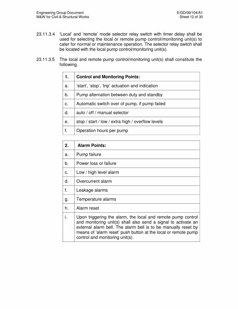
Engineering Group Document E/GD/09/104/A1 M&W for Civil & Structural Works Sheet 12 of 30
23.11.3.4 ‘Local’ and ‘remote’ mode selector relay switch with timer delay shall be
used for selecting the local or remote pump control/monitoring unit(s) to cater for normal or maintenance operation. The selector relay switch shall be located with the local pump control/monitoring unit(s).
23.11.3.5 The local and remote pump control/monitoring unit(s) shall constitute the
following.
1. Control and Monitoring Points:
a. ‘start’, ‘stop’, ‘trip’ actuation and indication
b. Pump alternation between duty and standby
c. Automatic switch over of pump, if pump failed
d. auto / off / manual selector
e. stop / start / low / extra high / overflow levels
f. Operation hours per pump
2. Alarm Points:
a. Pump failure
b. Power loss or failure
c. Low / high level alarm
d. Overcurrent alarm
f. Leakage alarms
g. Temperature alarms
h. Alarm reset
i. Upon triggering the alarm, the local and remote pump control and monitoring unit(s) shall also send a signal to activate an external alarm bell. The alarm bell is to be manually reset by means of ‘alarm reset’ push button at the local or remote pump control and monitoring unit(s).

Engineering Group Document E/GD/09/104/A1 M&W for Civil & Structural Works Sheet 13 of 30
23.11.3.6 During normal operation, the ‘local’ mode will be selected and thereby de-
activating the remote control functions of the pump control and monitoring unit(s) in the pump house. Thus, the remote pump control and monitoring unit(s) in consumer switch room shall be used for remote monitoring of pumps only.
23.11.3.7 For maintenance of the pumps, the local pump control and monitoring
unit(s) shall be used for controlling and monitoring of pumps manually at the ‘local’ mode.
23.11.3.8 For testing and maintenance of the Facilities Management System (FMS)
on the pumps, the maintenance personnel will have to select ‘remote’ mode. This will de-activate the control functions of the local pump control and monitoring unit(s). After testing and maintenance, the ‘remote’ mode will be switched back manually or automatically by means of timer delay.
23.11.3.9 The local and remote pump control and monitoring unit(s) shall be linked
by Armoured cable. 23.11.3.10 The output / input requirement between the remote pump
control/monitoring unit(s) and ITB shall be of the 4 – 20 mA linear type. The wiring shall be at least 1.5mm sq (minimum) twisted and shielded and installed in metal conduit / trunking.
23.11.3.11 Auxiliary contacts to the ITB for the connection to the FMS shall be
provided for the following schedule of points:
Schedule of points
a. Individual drainage pump ‘on’, ‘off’ status
b. Individual drainage pump trip alarm
c. High and extra high water level alarm
23.11.3.12 The contractor shall provide all necessary interfaces, high level
interfacing cards, other related provisions and also liaise with the FMS contractor.
23.11.3.13 The clause 23.11.3.8, 23.11.3.9 and 23.11.3.10 shall be applied to the
remote monitoring provision requirements for pedestrian underpasses projects.
23.11.3.14 The incoming main supply panel shall constitute the following.

Engineering Group Document E/GD/09/104/A1 M&W for Civil & Structural Works Sheet 14 of 30
1. Twin-filament indicator lamps:
a. Incoming main supply (one per phase)
2. Meters, switches, outlets, devices:
a. One (1) nos. of 13 Amp socket outlet
b. Voltmeter, hermetically sealed complete with phase selector switch and ammeter, hermetically sealed with maximum demand indicator.
c. Lamp test button
23.11.3.15 The individual motor and pump control panel shall constitute of the
following.
1. Twin-filament indicator lamps:
a. Incoming main supply (one per phase)
b. Outgoing main supply to motor (one per phase)
2. Meters, switches, outlets, devices:
a. Voltmeter, hermetically sealed complete with phase selector switch and ammeter, hermetically sealed with maximum demand indicator.
b. Moulded case circuit breaker
c. Lamp test button
d. Emergency stop button
23.12 MOTOR STARTERS 23.12.1 Motor starter/contactors shall be furnished and installed for mounting in
the MCP. The type of starter shall be compatible with the type and size of motor and the motor protection, as indicated. Contactors shall be non-sticking when de-energised, chatter free, operated without discernible noise and be suitable for 230 volt 50 Hz a.c. control operation.
Engineering Group Document E/GD/09/104/A1 M&W for Civil & Structural Works Sheet 15 of 30
23.12.2 Contactors used in starters shall be of the heavy duty type provided with heavy silver or silver alloy double-break contacts.
23.12.3 Starters shall be electromagnetically operated, electrically maintained,
three-pole type with arc control devices generally in accordance with IEC 947 standard rating, mechanical duty Class 1, electrically and mechanically interlocked where necessary.
23.12.4 Starters for motors up to 5 kW shall have thermally operated overload
units incorporating single phasing protection and ambient temperature compensation with under voltage release facilities. Motors over 5kW shall have thermistors fitted to operate the under voltage release and the necessary control units shall be supplied for these starters.
23.12.5 Each starter shall be complete with overload protection incorporating the
following features:
a) Overload protection in each phase supply. b) Adjustable over the range of 80 percent to 120 percent full load. c) Manual reset.
23.12.6 The voltage rating of the coil shall be such as to be compatible with other
components in the control circuit. 23.12.7 Where not indicated on the drawings, motor starters shall generally be of
the following types: a) Up to 2.2 kW motors - Direct-on-line (DOL) starters b) Above 2.2 kW up to 11 kW motors - Star-Delta starters (CT.SD) c) 15 kW motors and above - Solid state (Soft) or other reduced
voltage starters with a maximum starting current of 2 times the full load current.
23.12.8 The starters shall be suitable for intermittent duty with a maximum number
of operations per hour of 15 in accordance with BS 587 and shall be suitable for the following types of motors:
a) Single phase motors up to and including 1 kW which shall be of
either the repulsion start or capacitor start type with integral condensers and with built-in centrifugal switches.
b) Motors complying with BS2757 and rated for continuous duty to
BS2613 (CMR category).
23.12.9 All motors provided shall be suitable for the type of starting arrangement intended.

Engineering Group Document E/GD/09/104/A1 M&W for Civil & Structural Works Sheet 16 of 30
23.13 DIRECT-ON-LINE (DOL) STARTERS 23.13.1 DOL starters incorporate a direct switching electromagnetic contactor
together with overload protection relay and control equipment, suitable for starting the motors "direct-on-line".
23.13.2 Contactors in DOL starters controlling motors on fans, circulating pumps
and similar items of equipment which run continuously during the period of operation, shall have the following minimum rating:
Rated duty 8 hour, Utilisation Category AC 3, Mechanical Endurance Class 0.01 23.13.3 In all other cases, starters of the following minimum rating shall be used: Intermittent duty Class 0.1, Utilisation Category AC 3, Mechanical Endurance Class 0.3 23.14 REDUCED VOLTAGE STARTERS 23.14.1 General 23.14.1.1 Reduced voltage starters shall be provided in lieu of DOL where
required/specified. 23.14.1.2 Reduced voltage starters shall be one of the following types to suit the
requirements of the application:
a) Closed Transition "Star-Delta" (CT.SD) b) Closed Transition Auto Transformer (CT.AT) c) Solid state (soft) starter
23.14.1.3 Generally, reduced voltage starters shall be of the electro-magnetically
operated type complying with AS381 rated for intermittent duty, except for "run" contactors in starters controlling motors on fans, circulating pumps and similar items of equipment which run continuously during the period of operating. “Run” contactors shall be rated for ordinary duty and shall be suitable for continuous operation with main contacts closed and carrying rated current.
Engineering Group Document E/GD/09/104/A1 M&W for Civil & Structural Works Sheet 17 of 30
23.14.1.4 Reduced voltage starters shall be provided with the following:
a) No-volt coils with provision for external stop controls. b) Positive indication of the starter operation.
23.14.2 Closed Transition "Star-Delta" Starters (CT.SD) a) Closed transition "Star-Delta" starters shall be of an accepted type
and manufacture and capable of starting the motor from stopped to full load speed without interruption and in such a manner that the torque developed by the motor increases as uniformly as practicable during the whole starting sequence.
b) Each starter of this type shall include the following equipment:
(i) One (1) main-line contactor suitably rated for the motor. (ii) Star - Delta configuration contactors suitably rated for the
motor, mechanically and electrically interlocked to prevent simultaneous operation.
(iii) One (1) three pole overload relay. (iv) One (1) time delay relay, with at least 0-30 second adjustable
time delay period, to control the star to delta switching contactors.
(v) A suitably rated transition resistance bank such as to allow
approximately full load supply current when in circuit prior to opening of the star point. The short time rating of the resistors shall also be considered in relation to the length of their "in circuit" requirements.
(vi) A transition contactor suitably rated to facilitate connection of
the resistance bank during the transition period. (vii) Additional auxiliary contacts and timers required for the
transition sequencing operation. (viii) A closed transition with automatic changeover from the Star to
Delta positions activated by time delay relays for motors up to 40 kW.
Engineering Group Document E/GD/09/104/A1 M&W for Civil & Structural Works Sheet 18 of 30
23.14.3 Auto-Transformer Starters (CT.AT)
a) Starters shall be of an accepted type and manufacture and shall be
capable of starting the motor from idle to full load speed without interruption and in such a manner that the torque developed by the motor increases as uniformly as practicable during the whole starting sequence.
b) Auto-transformer starters shall have standard tappings and
Korndorfer or similar connections, and shall include the following equipment:
i) One (1) contactor operated auto-transformer type starter tapped
at 50 percent, 65 percent and 80 percent. It shall comprise of :
• Mainline contactor
• Run contactor
• Auto-transformer star point contactor
• All necessary auxiliary relays suitably rated for the motor ii) One (1) three-pole overload relay. iii) One (1) set of thermostats for auto-transformer protection with
relay and reset push button. Alternatively, thermistors embedded in the transformer windings and thermistor relay may be provided.
iv) One (1) time delay relay, with at least 0 to 30 seconds
adjustable time delay period, to control the start and run contactors.
23.14.4 Solid State (Soft) Starter Solid State Starter shall be of the thyristor controlled type for reduced
voltage starting provided smooth stepless acceleration. Maximum starting current shall be 200% of full load current.
23.15 CURRENT AND VOLTAGE TRANSFORMERS 23.15.1 Current and voltage transformers shall comply with BS EN 60044-1 and
BS EN 60044-2 as appropriate. They shall be of suitable ratio, output, type and class of accuracy for their function. Current transformer shall be single phase, epoxy resin moulded type. They shall withstand a continuous overload of 120%.
23.15.2 All transformers shall be wired with an identifying label giving type, ratio,
class, output and serial number.

Engineering Group Document E/GD/09/104/A1 M&W for Civil & Structural Works Sheet 19 of 30
23.16 AMMETERS 23.16.1 Ammeters shall be of class 1.5 accuracy to IEC 60051-1 with open scale
over the normal working range and compressed scale to indicate starting current. Mechanical zero adjustment shall be provided.
23.16.2 The ammeter selector switch shall be mounted on the front of the panel
and shall be of the rotary type with make-before break contacts for selection to read red-yellow-blue currents with R-Y-B marked clearly on the switch.
23.17 VOLTMETER 23.17.1 Voltmeter shall be of class 1.5 accuracy to IEC 60051-1. The range shall
be suitable for the voltage level to be indicated. 23.17.2 Voltmeter selector switch to be of seven position type to measure red-
yellow, yellow-blue, blue-red, red-neutral, yellow-neutral blue-neutral and zero voltage. The abbreviations, RY, YB, BR, RN, YN, BN & O are to be marked clearly on the switch.
23.17.3 The scales shall not be less than 90 angular degrees and the
designation shall be in Volts on matt-white plate. Anti-parallax and anti-reflecting types of platform/covers shall be used.
23.18 FUSE LINKS 23.18.1 All equipment shall be fitted with suitably rated fuses. Heaters, indications,
alarms, control circuits, measuring instruments, etc., shall each be fused separately.
23.18.2 Fuse links shall be of the high rupturing capacity type having non-
deteriorating properties as defined in BS 88. 23.19 MOULDED CASE CIRCUIT BREAKERS (MCCB) 23.19.1 Moulded case circuit breaker shall comply with BS EN 60947-2 with
appropriate rated short-circuit breaking capacity at 400V. The short circuit performance categories shall depend on the application of the breaker.
23.19.2 All MCCBs shall be of three-pole or two-pole as specified, thermal
magnetic type, with magnetic adjustable for MCCBs rated at 400A and above, independent manual operated to provide quick-made/quick-break, trip free mechanism so that the unit cannot be held closed against overload and short-circuit.
Engineering Group Document E/GD/09/104/A1 M&W for Civil & Structural Works Sheet 20 of 30
23.19.3 The rated normal current of the MCCBs shall be as indicated on the drawings and calibrated at 40
o C. Derating factor shall be applied to
MCCB installed in a totally enclosed cabinet. 23.19.4 Means shall be provided to padlock the switch in its OFF and ON
positions. 23.20 CONTROL AND AUXILIARY RELAYS 23.20.1 Control and auxiliary relays shall be provided where necessary to ensure
sound and effective operation of the MCPs. 23.20.2 Relay coils shall be suitably rated as required. Control voltage shall not
exceed 230 V a.c. 23.21 MINIATURE AIR-BREAK CIRCUIT BREAKER (MCB) Miniature circuit breakers (MCBs) shall incorporate fixed time/current
tripping characteristics calibrated in compliance to BS EN 60898 at ambient temperature of 40
o C. All MCBs protecting outgoing circuits shall
be the automatic type equipped with appropriate overload protection. The short circuit breaking capacity of the circuit breakers shall not be less than the maximum prospective fault levels at the points where the circuit breakers are installed. The Contractor shall be responsible to select and provide the correct type of circuit breakers for the protection of the different types of circuits.
23.22 CONTACTORS 23.22.1 Contactors shall comply with IEC 947 with interrupted ratings (I.R.),
mechanical duty class II and making and breaking category AC3. 23.22.2 Contactors used in starters shall be of the heavy duty type provided with
heavy silver or silver alloy double-break contacts. 23.22.3 Contacts shall be renewable butt type, solid copper hard silver faced, fully
shrouded main and auxiliary contacts and the design shall be such as to ensure effective freedom from contact bounce and sticking to the fixed and moving portion of the magnet assembly. Auxiliary contacts shall be provided as required by the Specification and/or Specification Drawings.
23.22.4 Contactor coils shall be fully tropicalised and suitable for continuous
operation at phase voltage with Class `B' insulation to BS 5000.
Engineering Group Document E/GD/09/104/A1 M&W for Civil & Structural Works Sheet 21 of 30
23.23 PUSH BUTTONS AND INDICATING LAMPS 23.23.1 Pushbuttons and indicating lamps shall be of matching design arranged
for single pole fixing and of small body size to allow close grounding.
23.23.2 Terminals shall be of the clamp type.
23.23.3 Start and stop pushbuttons shall be of the shrouded type.
23.23.4 Emergency stop pushbuttons shall be of the mushroom push type with stop/lock action.
23.23.5 Pushbuttons for use outdoors shall have watertight bezels incorporate with rubber membranes.
23.23.6 Indicating lamps shall normally be of the LED type.
23.23.7 Indicating lamps shall be arranged so that the LED shall be replaced from the front. They shall have shallow bezels that incorporate plastic lenses of the specified colour.
23.23.8 Engraved legend plates shall be fitted with all pushbuttons, indicating lamps and key switches. The minimum character height shall be 5mm.
23.24 LAMP TESTING FACILITY
On control consoles and mimic diagrams a lamp testing facility shall be
provided whereby all the panel lamps or sections of panel lamps can be illuminated by operating a non-locking pushbutton or pushbuttons for those sections. The button shall be engraved LAMP TEST.
23.25 SELECTOR SWITCHES 23.25.1 Selector switches shall be of the positive action rotary cam type
incorporating double break contacts of hard silver alloy. They shall have a minimum continuous rating of 10A and be of high breaking capacity.
23.25.2 Operating knobs shall of the type which positively indicate the position of
the switch. The switch positions shall be clearly marked on engraved legend plates.
23.26 ALARM BELLS AND BUZZERS They shall be of totally enclosed type and their operation shall not be
impaired or prevented by external interference.
Engineering Group Document E/GD/09/104/A1 M&W for Civil & Structural Works Sheet 22 of 30
23.27 PROTECTIVE RELAYS 23.27.1 Protective relays shall be of the microprocessor type with tripping
characteristics complying with BS 142. The microprocessor relays shall also comply with the Authority’s standards on Electromagnetic Compatibility (EMC).
23.27.2 A filter shall be fitted to the relays to equalise the pressure inside and
outside the case without admitting dust. 23.27.3 The relay contacts shall be capable of making and breaking the
maximum current which may occur under fault conditions in the circuit in which they are connected.
23.28 ISOLATORS 23.28.1 Isolators shall be rated at 500 V and be manufactured to BS EN 60947-3
or BS 5486. 23.28.2 Isolators shall be three-pole or single pole and neutral with the neutral
taken through a removable link. The mechanism shall be fully shrouded. 23.28.3 Isolators shall be of the pad-lockable type. 23.29 RESIDUAL CURRENT CIRCUIT BREAKERS
Residual current circuit breakers (RCCB) shall be the current operated type, 2 or 4 pole, suitable for operation on 230/400 volt, 50 Hz a.c. system and manufactured to comply with BS EN 61008-1. The residual current circuit breakers shall be the high sensitivity type with tripping current of 30mA and shall be so designed that the tripping action is completely independent of the supply voltage. The enclosure of the breakers shall be moulded from high quality insulating material. The main current carrying contacts of the breakers shall be fitted with anti-weld tips and the trip coil shall be completely encapsulated. A test button shall be provided at each breaker to enable the operation of the breaker to be checked regularly. The rupturing capacity of the residual current circuit breakers shall be adequate to withstand the prospective fault level at the respective points of application.
Engineering Group Document E/GD/09/104/A1 M&W for Civil & Structural Works Sheet 23 of 30
23.30 VOLTAGE-FREE CONTACTS (DRY CONTACTS) Voltage free dry contacts in the control panels shall be provided for remote
control and monitoring of status and alarm. They shall comprise a pair of contacts operated directly by the equipment but electrically separated such that no electrical potential derived from the equipment appears at the contacts. Voltage-free contacts shall also be used to complete external control, alarm or indication circuits. Cables from the dry voltage contacts to the Interfacing Terminal Boards (ITBs) shall be provided for the following interfacings:
• Integrate Supervisory Control System (ISCS)
• Civil Defence Equipment Monitoring System (CDEMS)
• Building Management System (BMS)
• Environmental Control System (ECS)
23.31 EMERGENCY STOP BUTTON 23.31.1 Emergency stop push buttons shall be provided and positioned in the
immediate vicinity of the associated motor drive in all cases where there is no direct line of sight or a distance greater than 2 metres between the motor and the controlling starter.
23.31.2 Emergency stop buttons for outdoor use shall be of weather-proof type. 23.32 LABELLING 23.32.1 Labels shall be made from white “Traffolite’ laminated white/black/white
and suitably engraved with black lettering and legends and shall be accepted by the Engineer prior to manufacture. Labels shall be securely fixed with stainless screws inserted into tapped holes in the equipment and secured by locking nuts at the rear.
23.32.2 Labels shall be provided for every panel to describe the duty of every
instrument, relay and item of control equipment mounted externally and internally to the MCP, panel sections and functions of all outgoing circuits.
23.32.3 Each unit contained in MCP shall be provided with name plate mounted
on each front door, to describe the rating and duty of each motor. 23.33 TESTS AT MANUFACTURER'S WORKS 23.33.1 The complete MCP shall be tested to ensure that the MCP being supplied
are in conformity with the Specification.

Engineering Group Document E/GD/09/104/A1 M&W for Civil & Structural Works Sheet 24 of 30
23.33.2 Testing shall include the following:
a) Mechanical tests including checking of all mechanical and electrical connections, interlocks, etc.
b) Insulation tests. c) Functional checks of all control circuits. d) Calibration of metering instruments, current transformer, etc. e) Functional checks of all protection devices. f) Any other tests as recommended by the manufacturer.
23.34 TESTS ON COMPLETION All electrical equipment included in this Contract shall be subjected to the
following tests as appropriate.
a) Continuity tests
b) Insulation tests
c) Earth Loop impedance tests
d) Mechanical operation tests including checking of all mechanical and electrical connections, interlocks, etc.
e) Test electric motors, starters and electrical switchgear for quietness
and current operation. Check rotation of all motors and actual current drawn by direct or current transformer connected meter.
f) Operation test of motor starters, control relays, level switches etc to
test the correct wiring for the operation sequences.
g) Full load test, which shall be sustained for at least one hour to ensure that all motors are operating as intended and all circuits are fused or otherwise protected correctly.
h) Visual inspections on the equipment or material including checks
related to the dimensions, appearance, finishing, markings, materials, connecting parts and construction standards, cleanliness of installation, etc.
Engineering Group Document E/GD/09/104/A1 M&W for Civil & Structural Works Sheet 25 of 30
23.35 PUMP CONTROLS FOR DRAINAGE SUMP PUMPING SYSTEM,
SEWAGE SUMP PUMPING SYSTEM AND SEWAGE EJECTOR PUMPING SYSTEM (FOR RAIL TRANSIT AND PEDESTRIAN UNDERPASSES PROJECTS)
23.35.1 The operation of pumps shall be carried out by the following methods:
a) Automatically by means of the ball float switches. b) Manually by means of start/stop push buttons at the local motor
control panel and emergency stop switches. 23.35.2 All electrical automatic controls and accessories shall be suitable for
operating at 24 volt a.c. The ball float switches at different levels shall be provided to correspond with the required depths of water to energise relevant controls to operate the pump and/or raise the alarm.
23.35.3 The drainage sump, sewerage sump and sewerage ejector pumping
system water level monitoring and pump control functions shall be as follows:
a) Overflow water level – when the water level reaches this level, the
control panels shall keep all pumps running and provide a “Overflow Water Level Alarm” signal.
b) Standby pump start level – when the water reaches this level, the
control panels shall start to run all pumps. c) Duty pump start level – when the water reaches this level, the
control panels shall start to run the duty pump. d) Pump stop level – when the water in the sump pit drops to this
water level, the control panels shall stop all pumps. e) Low water level – when the water in the sump pit drops to this water
level and the pumps are still running, the control panels shall provide a “Low Water Level Alarm” signal (for rail transit projects).
23.35.4 The de-watering sump pumping system water level monitoring and pump
control functions are as follows:
a) Overflow water level – when the water reaches this water level, the control panels shall keep the pump running and provide a “Overflow Water Level Alarm” signal.
b) Pump start level – when the water reaches this water level, the
control panels shall start to run the pump. c) Pump stop level – when the water in the sump pit drops to this
water level, the control panels shall stop the pump.
Engineering Group Document E/GD/09/104/A1 M&W for Civil & Structural Works Sheet 26 of 30
23.35.5 Alarm and Indication
The audible and visible indications for the system on the control panels shall consist of the following:
a) Red ‘Overflow Water Level’ alarm indicator with audible buzzer. b) Amber ‘Low Water Level” alarm indicator with audible buzzer. c) Red ‘Pump trip’ alarm indicator with audible buzzer. d) Green ‘Pump Run/ amber ‘Pump Stop’ indicators e) Red ‘Pump Supply Healthy’ indicator. f) ‘Incoming Supply” Red, Yellow, Blue Indicators. g) ‘Outgoing Supply’ Red, Yellow Blue Indicators. h) Amber ‘manual / auto' status indicator
23.36 PUMP CONTROLS FOR CD & NON-CD DRINKING WATER
BOOSTER PUMPING SYSTEM AND CD/PEACE-TIME COOLING WATER BOOSTER PUMPING SYSTEM
23.36.1 The operation of pumps shall be carried out by the following methods:
a) Automatically by means of the pressure switches. b) Manually by means of start/stop push buttons at the local motor
control panel and emergency stop switches. c) Remote control of pump operation on/off (for interface with
Environmental Control System only) 23.36.2 Water level sensors shall be provided in the CD drinking water tanks and
CD/peace-time cooling water tanks for monitoring the water levels to give the appropriate warning signals for the system. Water level sensors shall be of sensing electrode type, controller containing the switching circuitry and control relays and suitable for drinking and cooling water.

Engineering Group Document E/GD/09/104/A1 M&W for Civil & Structural Works Sheet 27 of 30
23.36.3 The sensing electrodes for the water level monitoring shall be as follow:
CD and non-CD Drinking Water Booster Pumping System
• High water level alarm
• Low water level alarm
CD/Peace-Time Cooling Water Booster Pumping System
• Overflow water level alarm (for interface with Environmental Control System only)
• Extra high water level alarm (for interface with Environmental Control System only)
• High water level alarm
• Low water level alarm 23.36.4 Alarm and Indication The audible and visible indications for the system on the control panels
shall consist of the following:
a) Red ‘Overflow Water Level’ alarm indicator with audible buzzer. b) Red ‘Extra High Water Level’ alarm indicator with audible buzzer.
c) Red ‘High Water Level’ alarm indicator with audible buzzer.
d) (Amber Alarm indicator shall be provided for interface with Environmental Control System only)
e) Amber ‘Low Water Level’ alarm indicator with audible buzzer
f) Red ‘Pump trip’ indicator with audible buzzer.
g) Green ‘Pump Run/ amber ‘Pump Stop’ indicators
h) Red ‘Pump Supply Healthy’ indicator.
i) ‘Incoming Supply” Red, Yellow, Blue Indicators.
j) ‘Outgoing Supply’ Red, Yellow Blue Indicators.
k) Amber ‘manual / auto' status indicator

Engineering Group Document E/GD/09/104/A1 M&W for Civil & Structural Works Sheet 28 of 30
23.37 PUMP CONTROLS FOR DRAINAGE SUMP PUMPING SYSTEM (FOR VEHICULAR UNDERPASSES PROJECTS WITH PUMP HOUSES)
23.37.1 The operational sequences of the pumps and alarms in accordance with
the water sensor levels shall be as followings.
Water sensor level Pump and alarm status
9th Overflow alarm
8th Extra high water level alarm. The switch shall
energise audible and visual alarm at the control panels.
7th 2
nd Standby Pump Start (if required)
6th 1
st Standby Pump Start: High water level alarm. The
switch shall energise audible and visual alarm at the control panels.
5th 2
nd Duty Pump Start (if required)
4th 1
st Duty Pump Start
3rd
Duty dewatering Pump Start
2nd
All Stop
1st Low water level alarm
23.37.2 Pumps shall alternate as duty and standby automatically after each
operation cycle. 23.37.3 In the event that the duty pump fails to start or is tripped, the first standby
pump shall take over as the duty pump automatically. 23.37.4 When the water level falls to the design stop level, the pump shall stop at
intervals sequentially. 23.37.5 The operation of the pump shall be carried out by the following methods:
a) Automatically by means of the sensing electrode via pump control/monitoring unit(s). The sensing electrode shall be suitable for use in water and storm water. Two numbers of emergency float level switches shall be provided to operate the duty pump(s) if water level reaches the extra high and overflow level when the sensing electrode fails to operate.
b) Manually by means of ‘start’ and ‘stop’ manual actuation on the local
pump control/monitoring unit(s).
c) Remote control and monitoring by means of remote pump control/monitoring unit(s) located at the consumer switch room. The unit(s) shall also link to the FMS via ITB.
Engineering Group Document E/GD/09/104/A1 M&W for Civil & Structural Works Sheet 29 of 30
23.38 EARTHING SYSTEM 23.38.1 General
a) The Contractor shall carry out soil resistivity tests in line with his
programs for construction of base slabs. It shall be early enough to allow 2 months for the redesign the earthing conductor if necessary.
The soil resistivity test shall use the Wenner 4 pin method and the
results submitted to the Engineer shall be endorsed by a Registered Licensed Electrical Worker. The Contractor shall select a minimum of 2 test locations for each station, subject to the acceptance of the Engineer. Five sets of tests shall be conducted at each location; each set at pin spacing of 2 m, 4 m, 6 m, 8 m and 10 m respectively.
b) The Contractor shall install the final earthing in accordance with the
final design. The installation and testing of the earthing system shall be in accordance with SS CP 16.
c) The Contractor shall prepare the necessary detailed working
drawings and test procedure and submit to the Engineer for acceptance.
23.38.2 Earth Mat Design Requirement
a) The earth mat design shall comply with IEEE Standard 80 and SS CP 16.
b) The earth mat should be designed to limit the coupling from any
lightning system earth mat to 110V when a discharge of 100kA lightning strike occurs.
23.38.3 Installation and Execution
a) The ringed earth mat shall comprise of earth rods inclusive of electrode pits and heavy duty cover and 95mm
2 bare stranded
copper wire laid 300mm below basement slab/ground level. The selection of electrode material shall be resistive to corrosion in the type of soil in which it will be used. If any jointing of earth rod is required, it shall be coupled together with silicon aluminium bronze coupling and the copper wire joints shall be by exothermic weld and must be inspected before backfilling.

Engineering Group Document E/GD/09/104/A1 M&W for Civil & Structural Works Sheet 30 of 30
b) One earth riser cable 185 mm
2 XLPE shall be brought from the earth
mat up through the basement floor or wall to each of the Substation rooms, Communication Equipment Room, SCS rooms and Relay room and other equipment rooms to the Engineer’s acceptance.
c) At each earth riser cable entry through the base slab, a tinned copper
waterstop sleeve shall be provided to prevent the ingress of water. The sleeve shall be coated with epoxy resin.
d) The Contractor shall co-ordinate with the relevant System wide
Contractors for termination of the earth riser cables onto the earthing busbar. The earthing busbar shall be provided by others.
e) The earth riser cables oversheath shall be green/yellow in colour. At
each connection to the busbar, the cable shall be labelled "MAIN EARTHING CABLE" plus the value of earthing resistance and the testing date shall be engraved on a template and fixed permanently above the earthing busbar.
f) The copper electrodes at the earth inspection chamber at ground
level shall have a label "Electrical Earth Do Not Remove".
23.38.4 Testing
a) Upon completion of the earth mat, a preliminary test shall be carried out by Contractor's Electrical PE. The earth meggers used for execution of the preliminary tests shall be calibrated by a recognised testing body and the calibrated results shall remain valid.
b) Plots of each resistance curves shall be submitted together with all
test results. c) Two weeks prior to the commissioning of the 22kV/400V power
supplies, the Contractor's Electrical Professional Engineer shall carry out a final earth test. It is essential that all inspection chambers are properly completed before the final earth test.
d) The Contractor's Electrical Professional Engineer shall submit 6
copies of endorsed earthing certificate (Declaration of the Earthing System), test results and as-built drawings to the Engineer immediately after completion of the final test.
Engineering Group Document E/GD/09/104/A1 M&W for Civil & Structural Works Sheet 1 of 2
CHAPTER 24
BRACKETS AND CAST-IN DUCTS FOR CABLES AND PIPES
24.1 CABLE BRACKETS 24.1.1 General In accordance with the schedule in the Particular Specification, certain
brackets to hold system-wide services shall be provided and delivered to the main site yard by the Systemwide Contractors, where required.
24.1.2 Storing, Distributing and Fixing The Contractor shall unload, store and distribute the brackets, fixings and
accessories supplied by the respective systemwide contractors. The Contractor shall fix the brackets in accordance with the approved
method statement. The position of any bracket / hanger shall not depart by more than 40mm from the design position.
24.1.3 Cast-In Sockets, Bolts and Washers Any cast-in sockets shall be hot dipped galvanised to BS 7371 Part 6 or
sherardized to BS 7371 Part 8, Class S1 with tail bars and with bolts, round washers and spring washers to suit.
24.2 CAST-IN DUCTS 24.2.1 All cable ducts shall be made from heavy gauge pitch fibre conduits to BS
4108 or ABS plastic pipe to BS 5391 Plastic sleeve joints shall be to BS 65. 24.2.3 Ducts shall be laid to the lines shown on the Drawings. 24.2.4 All ducts are to be fixed firmly in position and properly jointed to prevent the
inflow of grout during subsequent concreting operations. A wooden mandrel of the specified size is to be pulled through each duct immediately before and after concreting to the acceptance of the Engineer. The bore of each duct is to be left clean and free from any foreign matter and provided with a 5mm nylon pull-through rope protruding 1000mm at each end. In addition, both ends of the duct shall be provided with a temporary seal to prevent ingress of foreign matter.
24.2.5 Ducts are to be carefully aligned to enable service pipes and cables to be
removed for maintenance purposes and reinstated.
Engineering Group Document E/GD/09/104/A1 M&W for Civil & Structural Works Sheet 2 of 2
24.2.6 Duct runs are to be provided with bell-mouthed ends finished smooth. 24.2.7 Ducts beneath paved areas shall be laid so that the top of the duct is a
minimum of 750mm below pavement level. The duct shall be bedded on and surrounded by 150mm of concrete and the trench re-filled with selected material. The pull-through rope shall be fixed to a marker post at each end, and the marker posts shall be preserved by the Contractor for as long as is necessary.
24.2.8 Where possible, ducts shall be laid to falls and arranged so as not to have
local low points or parts where water could collect. 24.2.9 Wooden mandrels used for tests shall be supplied by the Contractor. The
wooden mandrels shall be 12mm less in diameter than that of the duct, 460mm long with a 45°chamfer of 25mm long at each end.
Engineering Group Document E/GD/09/104/A1 M&W for Civil & Structural Works Sheet 1 of 15
CHAPTER 25
STRAY CURRENT CONTROL AND TOUCH VOLTAGE PROTECTION
25.1 MRT STRAY CURRENT DRAINAGE AND MONITORING PROVISIONS 25.1.1 Throughout the MRT structures, a stray current drainage and monitoring
system will be installed with the exception of track on ballast founded on a sub-grade. The system will include the following:
(a) Reinforcing mesh embedded in concrete or screed beneath the track (b) Drainage terminal boxes connected to the mesh by means of a cable
(monitoring cable) fixed to terminals extending from the mesh (c) A drainage cable throughout the length of each trainway
interconnecting the drainage terminal boxes (d) Drainage cable connections from the appropriate drainage terminal
boxes to the traction sub-station negative busbar via diodes in a drainage panel.
(e) Reference electrodes located in tunnel and station to be used for
monitoring purposes. 25.1.2 For viaducts and bridges, where the track is on ballast, additional corrosion
control shall be provided in the form of an electrically insulating and waterproofing membrane between the ballast and the structure. The membrane shall be a bonded system in accordance with the requirements specified in MW Chapter 14, Waterproofing for Structures.
25.1.3 The electrical continuity of the reinforcing steel mesh shall be not more than
0.5 ohm-kilometre. Details of the reinforcement mesh and of the various arrangements for separating the mesh into discrete sections are given on the Drawings.
25.1.4 Weatherproof test boxes, shall be provided at the specified locations along
the trainway shown on the Drawings. 25.1.5 Drainage and monitoring cables shall be low smoke, halogen free and fire
retardant type with armour in accordance with the requirements specified in MW Chapter 23, Electrical Works. The cable shall have an insulation level of DC 2000V (for traction current of DC 750V) and be single core, extra-flexible, multi-stranded copper conductor, XLPE insulated type. The cable sizes shall be as follows:

Engineering Group Document E/GD/09/104/A1 M&W for Civil & Structural Works Sheet 2 of 15
(a) Drainage cable 185mm
2
(b) Monitoring cable (cable connecting the
mesh to the drainage terminal box) 35mm2
25.1.6 Reference electrodes shall be of zinc and shall be durable, reliable, and
replaceable. 25.2 ACCIDENTAL STRAY CURRENT PATHS FOR MRT STRUCTURES The following measures shall be taken to avoid accidental stray current
paths being generated along the trainway: - 25.2.1 Attachments for metal parapets, fascia, handrail and the like shall not come
into contact with the reinforcing steel in the MRT viaducts and structures. 25.2.2 Anchor bolts for viaduct and bridge bearings shall be isolated from the steel
reinforcement in viaduct and bridge beams and the supports. 25.2.3 All non-MRT services entering or passing through the cut-and-cover tunnels,
viaducts and other structures shall be fitted with insulated sections to segregate external services and utilities from the MRT earthing system.
25.2.4 Where local AC or DC power supplies are required, the sheaths and
armouring of the cables shall be insulated from the MRT structures and shall not be connected to the MRT traction earth system. Where such cables are buried, they shall be provided with an impervious and protected overall sleeving.
25.2.5 Sheaths of all telephone cables and equipment connected thereto shall be
insulated from the MRT structures and shall not be connected to the MRT traction earth system. Where buried, all cables shall be provided with an impervious and protected overall sleeving.
25.2.6 Where pipes entering MRT structures are metallic, these pipes shall be
insulated from the MRT structure by providing a suitable sheath or use of a duct so that all current paths from the structure to the incoming service are interrupted. Any duct shall comply with the requirements specified in MW Chapter 24 Brackets and Cast-In Ducts for Cables and Pipes
25.2.7 Insulation of the following installations from the structure within and along
the MRT trainway and within the depot track area shall be provided. These shall include to the following:
(a) Signalling equipment and their supports. (b) Platform screen doors (c) Blue light station support frame and siding telephone support frame.
Engineering Group Document E/GD/09/104/A1 M&W for Civil & Structural Works Sheet 3 of 15
(d) Metal pipes. (e) Lightning protection system to viaducts. (f) Earthing cables (g) Sectionalising switches and high-speed circuit breakers and their
supports. (h) Negative return and drainage cables. (i) Control boxes, test boxes, junction boxes etc and their supports.
25.3 TESTING AND MONITORING REQUIREMENTS FOR STRAY
CURRENTS 25.3.1 Test Equipment The following list of test equipment is provided as an aid in determining test
equipment requirements. Equipment appropriate to test and monitor the stray current control systems and/or its components shall be supplied by the Contractor who carries out the testing and monitoring.
(a) Voltmeter DC:
Multi-scale, centre zero minimum sensitivity 100000 ohms/volt, accurate to within one percent of full scale, covering the following full-scale ranges: 0-10 and 0-100 millivolts: 0-1, 0-10, 0-100 volts.
(b) Ammeter DC:
Multi-scale, maximum shunt drop of 20mV sensitivity, or millivolt meter and shunts, accurate to within one percent of full scale, covering the following full-scale ranges: 0-1, 0-10, 0-100 amperes.
(c) Resistivity meter:
Self-contained synchronous vibrator, battery powered unit. Instrument readings unaffected by resistance of leads or probes.
(d) DC power sources:
6- or 12-volt automotive type wet cell batteries or 12-volt DC gelled electrolyte in a sealed battery. For circuits with high internal resistance use two or more batteries, a DC generator, or cathodic protection rectifier.
(e) Test cable:
Single conductor cable, stranded copper assorted sizes and lengths to suit test conditions.
(f) Steel probes for making electrical contact to buried structures in
absence of test stations.
Engineering Group Document E/GD/09/104/A1 M&W for Civil & Structural Works Sheet 4 of 15
(g) Slide-wire resistors:
0-400 ohm, 15 ampere capacity over full range of adjustment.
(h) 22mm diameter by 203mm long saturated copper-copper sulphate reference half-cell.
25.3.2 Tests on Mesh Continuity Tests for electrical continuity on the reinforcement mesh shall be carried out
before concreting or screeding and all test results shall be properly recorded and submitted to the Engineer on the same day as the test. The Contractor shall not proceed with the next stage of work if the results of mesh electrical continuity fall outside the specified range. Under such circumstances, the Contractor shall identify the areas of poor connections and make good.
25.3.3 Tests on Insulation of Installations Electrical resistance testing shall be carried out on all anchor bolts, inserts,
handrail and equipment fixings etc described in Clause 25.2.1 through 25.2.7 and the results submitted to the Engineer for acceptance. Where test results are rejected, the rejected part shall be removed and reinstated in order to achieve the required resistance.
25.3.4 Tests on Reference Electrodes The Contractor installing the reference electrodes shall submit to the
Engineer for acceptance his proposals for a commissioning test to verify that each electrode is functioning properly. He shall justify the pass criterion selected for the test. Upon acceptance of the testing proposal, a commissioning test shall be carried out on each reference electrode. Any electrode that fails the test or is otherwise defective shall be removed and replaced.
25.3.5 Monitoring of Stray Currents Measurements on the voltage fluctuations of the mesh with respect to the
reference electrode shall be carried out to monitor the state of stray current leakage during trial running. Measurements are to be carried out by the trackwork contractor over a continuous 24-hour period as follows:
25.3.5.1 Measurements in the traction substations consisting of:
(a) Traction current at dc traction feeder for each bound (b) Negative busbar to earth resistance (rail potential) (c) Drainage current distribution and total drainage current.

Engineering Group Document E/GD/09/104/A1 M&W for Civil & Structural Works Sheet 5 of 15
25.3.5.2 Measurements of stray voltage shall be carried out with respect to zinc
reference electrodes or Cu/CuSO4 reference half-cell electrodes at the drainage terminal boxes. The extent of such testing shall be determined by the Engineer.
25.4 TOUCH VOLTAGE PROTECTION AT STATION PLATFORMS 25.4.1 General
The station platform shall be designed and installed with insulation system to prevent passengers on the platform from possible electric shocks caused by touch voltage when:
(a) boarding/alighting or
(b) touching the train or
(c) touching the Platform Screen Doors (PSDs) and another metallic elements e.g. column cladding, hand railings etc.
25.4.2 Protection Zone A ‘protection zone’ (as defined in clause 25.4.3 below) of the surrounding
platform area adjacent to the tracks shall be electrically isolated from the station structure/electrical earth or from traction earth.
25.4.3 Protection Zone Requirement The extent of the protection zone shall be :
(a) Vertically, at minimum 2.5 metres above platform finished floor level. (b) Transversely, at a minimum distance of 1.8 metres into the platform
from any part of the inner face of the platform screen doors (PSDs) assembly, and from any metallic clad platform edge column.
(c) Longitudinally, for the full length of the platform, and into the “buffer”
areas beyond to encompass anywhere that is within 1.8 metres of the PSD assembly end returns or within 1.8 metres of a train when stopped at the station at its most adverse allowable stopping tolerance.
25.4.4 Isolation Requirement The following measures shall be taken to avoid harmful touch voltages at
the platform:
(a) All appurtenances and the finishes to all structures (including floors, wall columns) that fall within the protection zone shall be electrically isolated from earth.
Engineering Group Document E/GD/09/104/A1 M&W for Civil & Structural Works Sheet 6 of 15
(b) The floor finishes to the platform from the platform edge and the remote side of the protection zone shall be electrically insulated from the structural slab below, and from all adjacent finishes and/or structures at the boundaries of the protection zone.
(c) All cladding, including vitreous enamel, on walls or columns shall use
electrically insulated fixings. Skirting around walls or columns that fall within the protection zone shall also be isolated.
(d) Insulated breaks in the finishes shall be provided at the boundaries of
the protection zone to ensure that the isolated areas are not earthed to the non-isolated areas.
(e) Metallic handrails that run along the platform edge in the buffer areas
and which fall within the protection zone shall be electrically isolated from the station structure/electrical earth.
25.4.4.1 Touch Voltage Protection Membrane
(a) The membrane insulation barrier to be used at platform edge areas
shall be of minimum 2.5mm thickness and be of minimum 5000 x 1011
ohm-cm electrical resistivity. Membrane shall be bonded type laid on the structural concrete or on a concrete screed and properly lapped and curtailed.
(b) The structural concrete or screed onto which the membrane is laid
shall have a trowelled finish and shall be inspected to ensure that no sharp points or other irregularities exist which may puncture the membrane.
(c) After laying, the membrane shall be protected from damage prior to
laying the platform finish. 25.4.5 Cladding at Platform Edge Column
The following additional measures shall be taken for cladding of column at platform edge:
a) No Metal cladding or trimming shall be used for column at platform
edge.
b) The supporting brackets for non-metal cladding (e.g. vitreous enamel, glass, granite, etc) shall be insulated from touch voltage between the PSD and column structure as follows:
(i) Insulation plates of sizes extending beyond the edges of the
brackets (see Figure 25.2 and 25.3) shall be provided.
Engineering Group Document E/GD/09/104/A1 M&W for Civil & Structural Works Sheet 7 of 15
(ii) Collar bushes between the supporting brackets and the
structure shall be provided. (iii) Where adhesive anchoring systems are used, electrically
resistant chemical grout and plastic spacers shall be provided to insulate the anchor bolts from the structure (see Figure 25.2).
c) The requirements for the insulation plates, collar bushes and plastic
spacers are given in Table 25.2. d) Each insulation detail (Detail A, B & C) when tested individually shall
meet the requirement for touch voltage insulation specified in Clause 25.5.2.6.
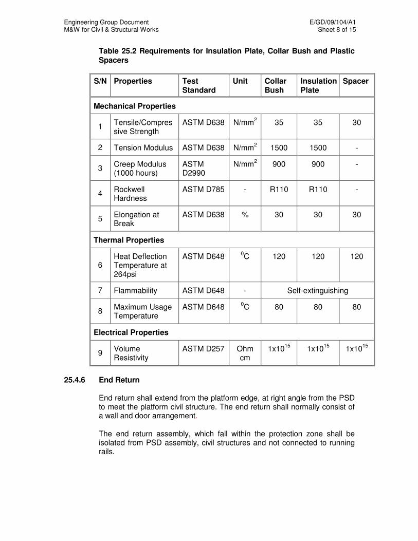
Engineering Group Document E/GD/09/104/A1 M&W for Civil & Structural Works Sheet 8 of 15
Table 25.2 Requirements for Insulation Plate, Collar Bush and Plastic Spacers
S/N Properties Test Standard
Unit Collar Bush
Insulation Plate
Spacer
Mechanical Properties
1 Tensile/Compressive Strength
ASTM D638 N/mm2 35 35 30
2 Tension Modulus ASTM D638 N/mm2 1500 1500 -
3 Creep Modulus (1000 hours)
ASTM D2990
N/mm2 900 900 -
4 Rockwell Hardness
ASTM D785 - R110 R110 -
5 Elongation at Break
ASTM D638 % 30 30 30
Thermal Properties
6 Heat Deflection Temperature at 264psi
ASTM D648 0C 120 120 120
7 Flammability ASTM D648 - Self-extinguishing
8 Maximum Usage Temperature
ASTM D648 0C 80 80 80
Electrical Properties
9 Volume Resistivity
ASTM D257 Ohm cm
1x10¹⁵
1x10¹⁵
1x10¹⁵
25.4.6 End Return End return shall extend from the platform edge, at right angle from the PSD
to meet the platform civil structure. The end return shall normally consist of a wall and door arrangement.
The end return assembly, which fall within the protection zone shall be
isolated from PSD assembly, civil structures and not connected to running rails.
Engineering Group Document E/GD/09/104/A1 M&W for Civil & Structural Works Sheet 9 of 15
25.4.7 Floor Finish Interface
The Contractor shall lay screed and floor finishes on top of the insulation membrane. At the lateral and longitudinal extremes of the insulated platform area a 10mm gap shall be provided to accommodate the membrane (minimum 2.5mm thick) plus a fire retardant insulated board of about 7mm thickness. The gap shall be finished at floor level with sealant. The sealant shall be non-conductive, shore hardness 50 (min.) and colour to suit floor finish. The membrane shall be trimmed off at finished floor level.
25.5 TESTING AND REQUIREMENTS FOR TOUCH VOLTAGE PROTECTION AT STATION PLATFORM
25.5.1 Test Equipment The following list of test equipment is provided as an aid in determining test equipment requirements. The Contractor responsible for carrying out the testing shall supply equipment appropriate to test the touch voltage protection systems and/or its components.
(a) Voltmeter DC:
Multi-scale, centre zero minimum sensitivity 100,000 ohms/volt, accurate to within one percent of full scale, covering the following full-scale ranges: 0-250 and 0-500 volts.
(b) Digital Insulation Tester (Megger):
Battery operated, with a resolution of better than 10,000 ohms per division, accurate to within two percent of full scale, with 2 ranges of rated testing voltage 250/500V DC.
(c) 300mm x 300mm copper plate. (d) Cotton cloth larger than 300mm x 300mm. Additional pieces to be on
hand. (e) Large rubber mat 2mm thick to place the test instruments and as well
as to accommodates the tester. (f) A coil of 2.5mm
2 PVC cable sufficiently long to connect to the nearest
earth point. (g) Connectors for voltage check terminals. (h) Suitable weights to press down the copper plate.
The Contractor shall ensure that all test instruments are calibrated by an accredited testing laboratory before carrying out the test.
Engineering Group Document E/GD/09/104/A1 M&W for Civil & Structural Works Sheet 10 of 15
25.5.2 Insulation Measurement on Platform Floor
25.5.2.1 General
The Contractor shall carry out electrical insulation measurement on the platform flooring, within the protection zone in two stages. The stages shall be as follows:
(a) Pre- Platform Floor Finish Laying
(b) Post Platform Floor Finish Laying
25.5.2.2 Pre-Platform Floor Finish Laying The measurement shall be taken when the platform has been completed
with the membrane laid. The membrane must be clean and dry, free from debris during the measurement.
Types of measurement to be made are:
(a) Points to Ground (dry condition) (b) Points to Ground (damp condition)
25.5.2.3 Post Platform Floor Finish Laying The measurement shall be taken when the platform has been completed
with the membrane laid and floor finish (e.g. granite) laid. The platform flooring must be clean and dry, free from debris during the measurement.
Types of measurement to be made are:
(a) Points to Ground (dry condition) (b) Points to Ground (damp condition)
25.5.2.4 Method of Measurement A suggested circuit diagram and details is shown in Fig 25.1. Measurement shall be carried out as follows: (3 measurements per
location). Apply the prescribed voltage of 250V dc and take the resistance reading
one (1) minute after the application of voltage or once the reading has reached equilibrium under dry conditions for each location. Damp conditions shall be simulated by placing two damp cotton cloths directly beneath the copper plate.
Engineering Group Document E/GD/09/104/A1 M&W for Civil & Structural Works Sheet 11 of 15
25.5.2.5 Measurement Locations Number of locations to be measured on each bound of the platform shall be
as follows: Pre Platform Floor Finish Laying One (1) location per train door. Post Platform Floor Finish Laying
(a) For aboveground stations, the measurement shall be performed at one (1) location per train door at each bound of the platform.
(b) For underground stations, the measurement shall be performed at two
(2) locations per train door, in front of each screen door and one (1) location per end return at each bound of the platform.
25.5.2.6 Passing Requirement The minimum insulation levels shall be:
A minimum platform floor to electrical earth resistance of 10,000 and 35,000 ohm over a 300mm x 300mm area at 250V DC under damp and dry conditions respectively.
25.5.2.7 Rectification The Contractor shall not proceed with the next stages of work if the results
of electrical insulation test fall outside the specified range. Under such circumstances, the Contractor shall identify the areas of poor insulation and make good.
25.5.3 Insulation Measurement of Installations within the Protection Zone 25.5.3.1 General The Contractor shall carry out electrical resistance measurement on all
appurtenances and finishes to all structures, including walls, platform columns, PSD top support frame, end return cladding/doors, cladding above PSD header, ceiling panel below 2.5 metres and metallic handrails that run along the platform edge in the buffer areas and which fall within the protection zone.
25.5.3.2 Passing Requirement The minimum insulation levels shall be: A metallic finishes (e.g. handrails, metallic cladding, etc) to electrical earth
resistance of 35,000 ohm at 250V DC under dry condition.
Engineering Group Document E/GD/09/104/A1 M&W for Civil & Structural Works Sheet 12 of 15
25.5.4 Method Statement and Test Report 25.5.4.1 The test method and procedures including the format for recording the test
results shall be submitted to the Engineer for acceptance at least four weeks before the test.
25.5.4.2 Upon completion of the test, Test Report shall be endorsed by the
Contractor’s Professional Engineer and submitted to the Engineer for acceptance.
25.5.4.3 Where test results are rejected, the rejected part shall be removed and
reinstated in order to achieve the required resistance. 25.6 CIVIL/PSD INSTALLER INTERFACE 25.6.1 Prior to the final connection of the bonding cable to the PSD structure by
the PSD installer, all relevant tests shown in Table 25.1 shall be successfully carried out and shall pass the required minimum insulation level.
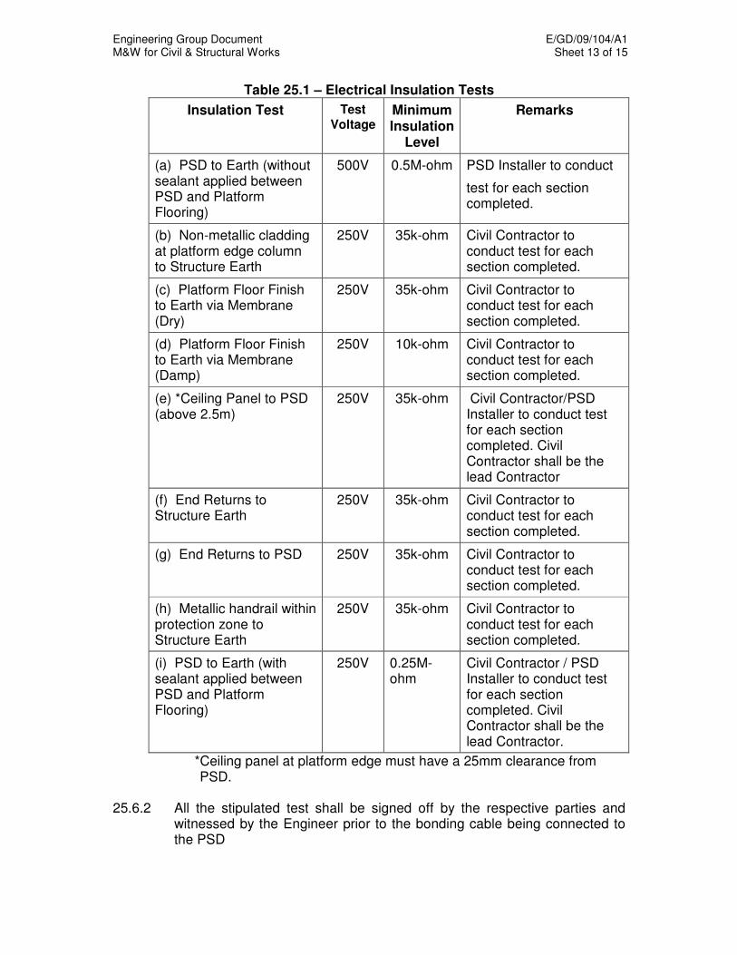
Engineering Group Document E/GD/09/104/A1 M&W for Civil & Structural Works Sheet 13 of 15
Table 25.1 – Electrical Insulation Tests
Insulation Test Test
Voltage Minimum Insulation
Level
Remarks
(a) PSD to Earth (without sealant applied between PSD and Platform Flooring)
500V 0.5M-ohm PSD Installer to conduct
test for each section completed.
(b) Non-metallic cladding at platform edge column to Structure Earth
250V 35k-ohm Civil Contractor to conduct test for each section completed.
(c) Platform Floor Finish to Earth via Membrane (Dry)
250V 35k-ohm Civil Contractor to conduct test for each section completed.
(d) Platform Floor Finish to Earth via Membrane (Damp)
250V 10k-ohm Civil Contractor to conduct test for each section completed.
(e) *Ceiling Panel to PSD (above 2.5m)
250V 35k-ohm Civil Contractor/PSD Installer to conduct test for each section completed. Civil Contractor shall be the lead Contractor
(f) End Returns to Structure Earth
250V 35k-ohm Civil Contractor to conduct test for each section completed.
(g) End Returns to PSD 250V 35k-ohm Civil Contractor to conduct test for each section completed.
(h) Metallic handrail within protection zone to Structure Earth
250V 35k-ohm Civil Contractor to conduct test for each section completed.
(i) PSD to Earth (with sealant applied between PSD and Platform Flooring)
250V 0.25M-ohm
Civil Contractor / PSD Installer to conduct test for each section completed. Civil Contractor shall be the lead Contractor.
*Ceiling panel at platform edge must have a 25mm clearance from PSD.
25.6.2 All the stipulated test shall be signed off by the respective parties and
witnessed by the Engineer prior to the bonding cable being connected to the PSD
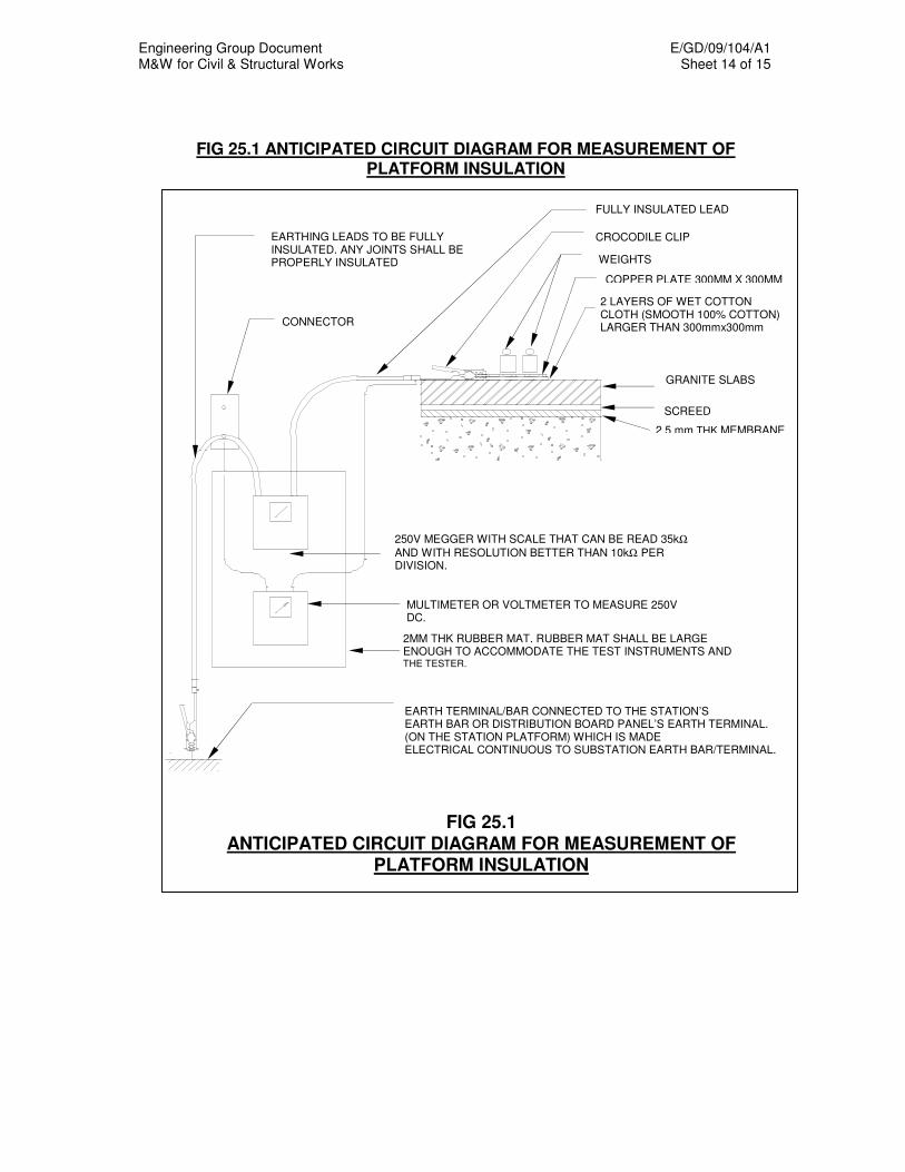
Engineering Group Document E/GD/09/104/A1 M&W for Civil & Structural Works Sheet 14 of 15
FIG 25.1 ANTICIPATED CIRCUIT DIAGRAM FOR MEASUREMENT OF PLATFORM INSULATION
2 LAYERS OF WET COTTON CLOTH (SMOOTH 100% COTTON) LARGER THAN 300mmx300mm
WEIGHTS
EARTHING LEADS TO BE FULLY INSULATED. ANY JOINTS SHALL BE PROPERLY INSULATED
FULLY INSULATED LEAD
CROCODILE CLIP
COPPER PLATE 300MM X 300MM
CONNECTOR
GRANITE SLABS
SCREED
2.5 mm THK MEMBRANE
250V MEGGER WITH SCALE THAT CAN BE READ 35kΩ
AND WITH RESOLUTION BETTER THAN 10kΩ PER DIVISION.
MULTIMETER OR VOLTMETER TO MEASURE 250V DC.
2MM THK RUBBER MAT. RUBBER MAT SHALL BE LARGE ENOUGH TO ACCOMMODATE THE TEST INSTRUMENTS AND THE TESTER.
EARTH TERMINAL/BAR CONNECTED TO THE STATION’S EARTH BAR OR DISTRIBUTION BOARD PANEL’S EARTH TERMINAL. (ON THE STATION PLATFORM) WHICH IS MADE ELECTRICAL CONTINUOUS TO SUBSTATION EARTH BAR/TERMINAL.
FIG 25.1 ANTICIPATED CIRCUIT DIAGRAM FOR MEASUREMENT OF
PLATFORM INSULATION

Engineering Group Document E/GD/09/104/A1 M&W for Civil & Structural Works Sheet 15 of 15

Engineering Group Document E/GD/09/104/A1 M&W for Civil & Structural Works Sheet 1 of 1
CHAPTER 26
TELEPHONE INSTALLATIONS 26.1 TEMPORARY TELEPHONE INSTALLATIONS 26.1.1 Telephone installations shall be installed in accordance with the
requirements and specifications of the authorised/appointed public telecommunication licensees (PTLs) and telecommunication system licensees (TSLs).
26.1.2 All materials required shall be purchased either from the
authorised/appointed PTLs/TSLs, or their licensed suppliers. 26.1.3 The Contractor shall liaise with the authorised/appointed PTLs/TSLs to
ensure that their requirements are fully complied with and shall obtain their subsequent approval, including preparation and submission of drawings.
26.2 LEAD-IN PIPES 26.2.1 Permanent lead-in pipes to structures shall be of medium duty, seamless
galvanised steel pipes with a nominal bore diameter of 100mm to BS 1387. The number and construction of lead-in pipes and associated accessories shall be in accordance with the requirements of the Telecommunication Facility Co-ordination Committee (TFCC), Infocomm Development Authority of Singapore (IDA) Code of Practice for Info-Communications Facilities in Buildings (COPIF), authorised/appointed public telecommunication licensees (PTLs) and telecommunication system licensees (TSLs).
26.2.2 The entry point of the lead-in pipe shall be water-tight. The external end
point of pipes shall be threaded, capped and indicated by a marker. 26.2.3 A nylon/polyethylene rope of 4-core or multi-strand type with overall
diameter of 6mm shall be provided in each pipe to facilitate cable pulling. 26.3 TELEPHONE MANHOLES Telephone manholes shall be constructed at the locations and to the details
shown on the Drawings and to the requirements of the Telecommunication Facility Co-ordination Committee (TFCC), Infocomm Development Authority of Singapore (IDA) Code of Practice for Info-Communications Facilities in Buildings (COPIF), authorised/appointed public telecommunication licensees (PTLs) and telecommunication system licensees (TSLs).
26.4 EXPRESSWAY EMERGENCY TELEPHONE SYSTEM 26.4.1 The Expressway Emergency Telephone System shall be provided by a
SWC. The Civil Contractor shall co-ordinate with this SWC.
Engineering Group Document E/GD/09/104/A1 M&W for Civil & Structural Works Sheet 1 of 7
CHAPTER 29
TURFING AND PLANTING 29.1 GENERAL All turfing and planting works shall be carried out to the requirements and
general satisfaction of National Parks Board (NParks) or relevant authorities (e.g. HDB, JTC). All works in connection with turfing and tree planting, shall be considered accepted, only upon the successful handover to the respective landowners or their agent.
29.2 TOPSOIL Topsoil shall be fertile natural red/brown topsoil transported to the site, free
from stones, clay, wood, sod, rubbish, roots, stumps or other extraneous material and obtained from naturally well drained area. Topsoil shall neither be excessively acidic or alkaline and shall be free from any toxic matter liable to be harmful to plant growth.
Topsoil shall generally be reasonably loose in a form containing not more
than 10 - 15% of moisture content.
All topsoil shall be mixed with organic matter in the proportion of 3:1. This mixture shall be spread uniformly over the site, slopes and/or berms etc. where directed and shall be lightly watered if necessary, and then tamped with wooden tampers and trimmed to a consolidated thickness of 100mm for turf, 600mm for shrub areas or as specified. The Contractor shall be responsible for providing and fixing the turf promptly after spreading the topsoil and tamping in order to prevent erosion. A thin layer of topsoil shall be broadcast on the turf to fill all depressions and give a level finish.
29.3 PLANTING 29.3.1 Turf For playing fields and for general turfing, Cow Grass (Axonopus
compressus) shall be used. Where a very fine lawn is specified in the Particular Specification, the following finer grasses shall be used:
(a) Serangoon Grass (Digitaria didactyla) - normally used for golf greens
(b) Bermuda Grass (Cynodon dactylon) - often used for lawn tennis
courts

Engineering Group Document E/GD/09/104/A1 M&W for Civil & Structural Works Sheet 2 of 7
(c) Siglap Grass (Zoysia matrella) - found in the better house gardens.
The choice of specie to be used shall be decided by the Engineer. All turf supplied by the Contractor shall be of healthy and vigorous stock and from accepted sources. The grass or turf shall be cut square and approximately 0.3m x 0.3m (0.09 m
2) in size, and be 50mm in thickness. All
turf supplied shall be free from weeds, especially Mimosa pudica and care shall be taken to include as much of the root growth as possible. The turf shall not be broken up into small pieces for planting and shall be planted as soon as possible after being cut. The turf sods shall be laid side by side on the ground with gaps not exceeding 30mm. In the case of banks each sod shall be held in position by wooden pegs to prevent movement or displacement of any kind, and the turfing shall thereafter be tamped down and rolled (except on slopes) with a suitable hand roller. The pieces of turf shall be sunk into the ground so that they are flush with the surface. All depressions between the pieces of turf shall be filled with topsoil. The turfing shall on completion present a uniform and regular appearance. After planting of turf and watering of the turfed areas no additional spreading of organic matter on the turfed areas shall be allowed.
For play fields, the field shall be finished with a 25mm thick topdressing consisting of topsoil only and spread evenly over the grass. The topdressing shall be repeated at monthly intervals until an even surface is obtained. Normally this is achieved after six topdressings and rollings.
29.3.2 Plants
All trees, shrubs and groundcover to be used under this Contract (herein after collectively referred to as `Plants') shall be of varieties, sizes and quantities shown in contract drawings. All plants must be positioned in accordance with the approved landscape design including allowance for safe depths and root barriers for protection of any shallow structures below the surface. Positioning of plants shall comply with the requirements given in the NParks Regulations. All plants shall be of cultivated stock. The Contractor shall furnish all plants shown on the contract drawings. No substitutions or omissions thereof shall be permitted unless accepted by the Engineer. All plants shall be typical of their respective species or variety and shall have normal growth and be legibly tagged with proper botanical names.
The height of a tree or single stem palm (measured from the collar of the tree to the average height of the top branches) shall be not less than the minimum size designated on the contract drawings.

Engineering Group Document E/GD/09/104/A1 M&W for Civil & Structural Works Sheet 3 of 7
The trunk of each tree shall be a single trunk growing from the single unmutilated crown of root. No parts of such trunks shall be conspicuously crooked as compared with normal trees of the same variety. Such trunks shall be free from wound, abrasions, or other damage from whatever cause. No pruning having a diameter exceeding 250mm shall be present on any trunk of such trees. All pruning must be clean cut without damaged bark/ tearing. Shrubs and cluster palms used in the works shall meet the requirements for spread or height specified on the contract drawings. Measurement for the height of shrubs shall be taken from the ground level to the average height of the tallest branches of the shrubs and not to the longest branch or stem. Single stemmed or thin plants shall not be accepted. The side branches shall be generous, well twigged and all shrubs, as a whole, shall be well branched to the ground.
All plants must come with pots or plastic bags in which they were originally grown and established in the nursery. The only exception being instant plants and large shrubs that have to be specially transplanted. All plants are to be removed from their original growing receptacles prior to installation. They should be arranged in a manner such that the leaves complement each other and are within touching distance of the other and not overlapping one another unless specified to the contrary. All planting works shall have the appearance of established growth. Plants shall be arranged with their foliage showing off their best face so that the intended design effect shall be fully realised. Rooted cuttings of ground covers shall be laid at approximately 200 mm centres or as specified.
29.3.3 Planting Holes Planting holes shall comply to the NParks Regulations. Minimum sizes shall
be: (a) 1.5m x 1.5m x 1.0m for instant tree planting
(b) 1m x 1m x 1m for tree and palm planting
(c) 0.6m x 0.6m x 0.6 m for shrubs planting All planting holes shall be backfilled with topsoil of a quality as specified in
the section on topsoil above.
All saplings shall be securely staked and tied as specified in the NParks Regulations. All semi-matured trees shall be staked by guying or by ground anchors as specified and as directed by the Engineer.

Engineering Group Document E/GD/09/104/A1 M&W for Civil & Structural Works Sheet 4 of 7
Roots and root balls of all plants shall be kept damp and thoroughly protected from the sun and wind during transportation to the site at all times until planted. All plants shall accurately set in the centre of the planting holes and at the same depth to final ground surface levels as upright in the holes before backfilling. All backfill shall be brought to a finished level (after settlement) identical to the level of the surrounding area except directed otherwise by the Engineer. Backfill shall not be compacted by ramming.
29.3.4 Transplanting Arrangements for existing trees identified for transplanting shall meet all the
requirements given by NParks. 29.4 MAINTENANCE 29.4.1 Maintenance Period The Contractor shall maintain all completed works and rectify all defects for
a period commencing from the contract completion date up to end of the defects liability period or until the handover to the relevant authority/ landowner whichever is later.
During the period, the Contractor shall be responsible for the necessary
horticultural maintenance eg. pruning, weeding, watering, forking, mowing and replacement of any defective works to the acceptance of the Engineer.
The period of maintenance shall commence only after the acceptance in
writing of the completion of the entire works by the Engineer. 29.4.2 Watering All turfing and planting shall be watered regularly in the absence of sufficient
rainfall as required to keep the plants healthy It is the responsibility of the Contractor to water and spray water to remove
dust to all plants regularly. 29.4.3 Weeding All weeds found growing in the landscape and turfing area under
maintenance must be removed. All plant beds shall be weeded weekly. All Turfing shall be weeded at least twice a month
Engineering Group Document E/GD/09/104/A1 M&W for Civil & Structural Works Sheet 5 of 7 Grass growing in the cement joints of footpaths and along the edge of the
roads adjacent to or directly fronting the side tables, centre medians, circuses etc. shall be cut or manually weeded out and cleared.
29.4.4 Forking All plant beds must be forked fortnightly to loosen the soil and provide
sufficient aeration for the roots. A hoe (Changkol) should not be used to loosen the soil so as not to cause damage to the roots.
29.4.5 Pruning Plants must be pruned when necessary. Pruning shall be done with clean,
sharp tools to produce a clean-cut face. Dead wood and broken or badly bruised branches shall be removed. Main
leaders shall not be cut. Plants on the road reserve during the maintenance period shall be pruned
back clear of the kerb line, at crossing and junctions for visibility of traffic and pedestrians, and as required by the Engineer for safety reasons.
29.4.6 Topdressing Plant with exposed root planting beds and turfing with low topsoil level and
those affected by rainwater splashing and erosion shall be topdressed as and when required.
29.4.7 Application of Pesticide All foliage, flowering plants and trees must be treated with fungicide, mitcide
and an insecticide as and when directed by the Engineer. 29.4.8 Application of Fertiliser Slow release of Nitrogen, Phosphorus, Potassium (NPK) combined with fast
release organic fertiliser shall be applied regularly to ensure healthy plant growth, repeating the application once every 4 - 6 weeks, or when directed by the Engineer. All trees, foliage and flowering plants are to be given fertiliser according to the dosage, fertiliser type and frequency as shown in Table 29.1.

Engineering Group Document E/GD/09/104/A1 M&W for Civil & Structural Works Sheet 6 of 7
Table 29.1 - Fertiliser dosage type and frequency
Fertiliser Plants Dosage Frequency
Eg :12N : 12P 17K : 2Mg + Te, 15N : 15P : 15K
1) Trees 30 g/plant once/month
2) Palms 10 g/plant once/month
3) Foliage and flowering shrubs
30 g/m2 once/month
Turf shall be manured with a complete compound NPK fertiliser. This shall
be applied at the rate of 125 kg/ha of grass after all weeds have been removed. The fertiliser shall be mixed with the topdressing and spread evenly over the field one month after planting and then again three months later.
29.4.9 Replacement of Plants
All dead plants/turf and plants not growing properly are to be replaced by healthy plants/turf of the same species at the Contractor's own expense.
29.4.10 Mowing and Rolling of Turf After one month's growth, the grass shall be cut with a suitable rotary
mower to encourage the grass to creep on the ground instead of growing upright. This operation shall be repeated at fortnightly intervals until the ground is completely covered with grass. Thereafter the grass shall be cut regularly.
Approximately two months after planting, when the grass has grown and
produced a continuous cover over the whole area, the whole of the turfed areas shall be lightly rolled (roller shall not exceed 150 kg in weight) to an even surface. Rolling shall be repeated at monthly intervals until the surface is accepted by the Engineer.
Grass shall be close cut as short as possible following the general contours
of the ground. The stock or blade of the grass after each cutting shall not stand higher than 20mm above the ground level. On fairly extensive and open grass areas, side tables or fields, the Contractor shall use mechanical mowers powered by small tractors.

Engineering Group Document E/GD/09/104/A1 M&W for Civil & Structural Works Sheet 7 of 7 29.4.11 Turf Edging The edge of all side tables, and other grassed areas adjoining roadways,
footpaths, kerbs, dividers and concrete paved areas shall be cut back to proper straight lines or curves as the case may be, and trimmed thereafter to produce a neat and tidy appearance. This work shall be carried out immediately after the grass in the area has been cut.
Where the existing ground is around established and mature tree (with girth
of above 200mm measured at 1m above ground level) or around street furniture, the Contractor shall level the surrounding ground and employ a weed eater or other grass cutting machine operated by nylon string cutting "blade", to close cut the grass right up to the bases of trees or street furniture without damaging the bark or furniture.
To avoid damaging shrubs, flowering plants or young trees (with girth less
than 200mm), the Contractor shall cut grass right up to the edge of the flower beds only or the weeded areas of such plants.
29.5 PLANTER BOXES Aggregate laid in planter boxes shall be clean, smooth and free from dirt
and grease. Topsoil to indoor planters shall be vermiculite granules and shall contain no
deleterious or foreign matter. Granulated peat shall be compressed and laid in the planter box on a
prepared layer of rounded aggregate. 29.6 INSPECTION AND ACCEPTANCE OF WORKS Upon completion of the Works, the Contractor shall request the Engineer in
writing to inspect and determine whether all plants are acceptable to the Engineer Should any plant be unacceptable to the Engineer, the Contractor shall replace all such plant at his own expense as and when directed by the Engineer and to the acceptance of the Engineer.
The Contractor must ensure that all plant beds are tidied up and free from any debris or dead plant materials immediately on completion of the planting works. All areas affected by horticulture activities must be thoroughly cleaned and soil stains etc. removed to the acceptance of the Engineer. Prior to handing over of the work at contract completion and at the end of the defects liability period, all plants must be groomed and neatly trimmed.

Engineering Group Document E/GD/09/104/A1 M&W for Civil & Structural Works Sheet 1 of 1
Checklist for references to PS, GS & Authority’s Drawings
in the M&W Specification
Chapter No. Particular Specification
Clause ref.
General Specification
Clause ref.
Authority’s Drawing(s)
Clause ref.
Chapter 1 - - -
Chapter 2 2.2 2.2 -
Chapter 3 - - -
Chapter 4 - - -
Chapter 5 - 5.6.1.13 -
Chapter 6 - 6.27 -
Chapter 7 - - -
Chapter 8 - - -
Chapter 9 9.22 - -
Chapter 10 - 10.8.3 -
Chapter 11 - - -
Chapter 12 12.5.2 - -
Chapter 13 - 13.3.1.4 -
Chapter 14 - 14.7 Fig.2(a)
Chapter 15 - 15.2.2 -
Chapter 16 - - -
Chapter 17 - - -
Chapter 18 - - -
Chapter 19 - - -
Chapter 20 - - -
Chapter 21 - - -
Chapter 22 Not Used
Chapter 23 - - -
Chapter 24 24.1.1 - -
Chapter 25 - - -
Chapter 26 - - -
Chapter 27 Not Used
Chapter 28 Not Used
Chapter 29 29.3.1 - -
Engineering Group Document E/GD/09/104/A1 M&W for Civil & Structural Works Sheet 1 of 1
1.1 CLAUSES TO BE INCORPORATED INTO PARTICULAR SPECIFICATIONS
AS REQUIRED 1.1.1 ADMINSTRATIVE CHARGE For non-compliance with 11.8.4 of the Materials & Workmanship
Specification, an administrative charge of $20/m3 on the quantity of concrete
at risk shall be deducted from the Contract Sum as in 11.8.5.
When successive group failures lead to the overlap of the quantity of concrete at risk, such quantities shall be considered only once. Deduction of the administrative charge shall not relieve the Contractor of his contractual liabilities, including the works stated in 11.8.6 of the Materials & Workmanship Specification.
1.2 SURFACE FINISH OF CONCRETE 1.2.1 For structural element where Class F3 finish is specified, the Contractor shall
provide a mock-up structure for the Engineer’s acceptance. The mock-up structure shall incorporate all expected features on the permanent structure, eg. Feature grooves and recesses etc. The Engineer will access the standard of this mock-up structure and, if not acceptable, then further mock-up structure shall be erected until a satisfactory standard is achieved. Once an acceptable mock-up structure has been constructed the Engineer will give approval for the commencement of permanent works and the mock-up shall be retained as a measure of the acceptability of these permanent works. The Contractor shall maintain the mock-up structure until the Engineer directs their removal.
For Viaduct Columns the Contractor shall provide a mock-up structure for the Engineer’s acceptance.
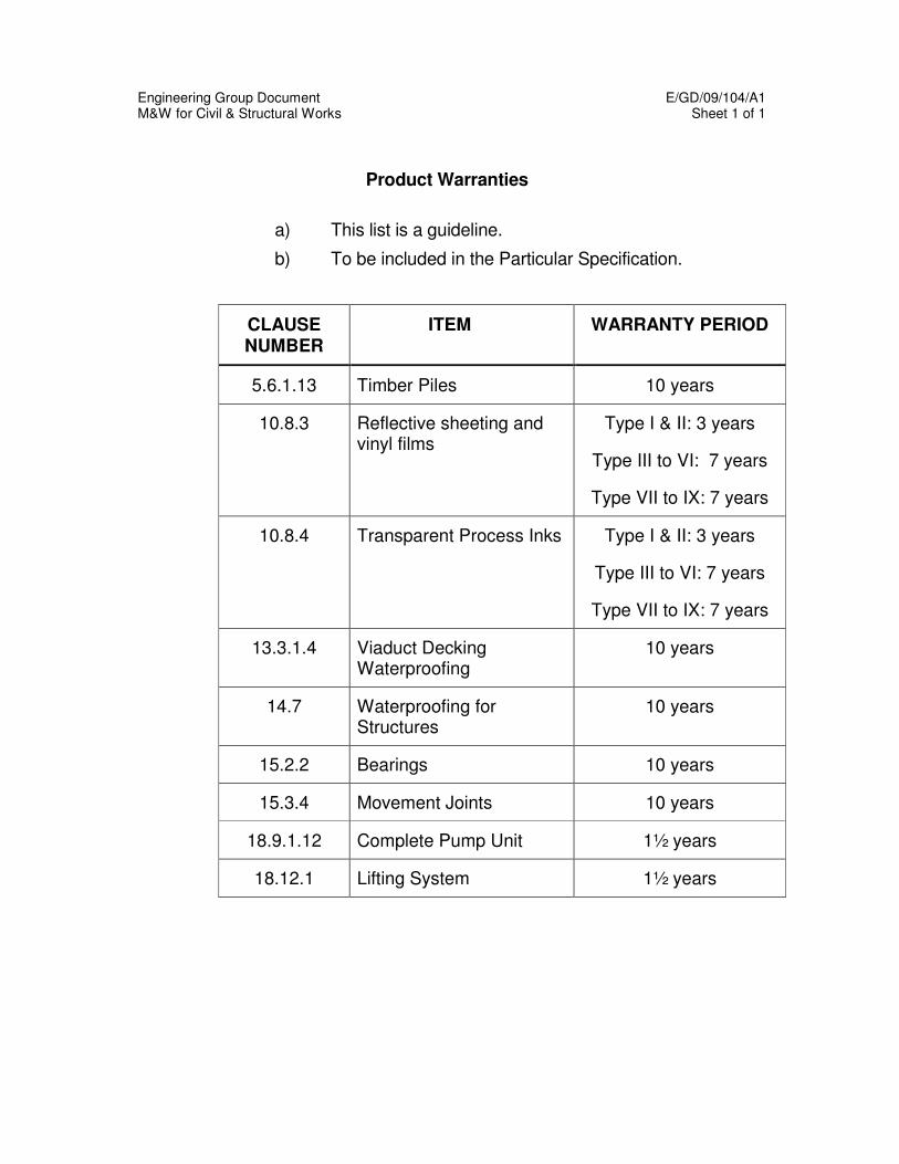
Engineering Group Document E/GD/09/104/A1 M&W for Civil & Structural Works Sheet 1 of 1
Product Warranties
a) This list is a guideline.
b) To be included in the Particular Specification.
CLAUSE NUMBER
ITEM WARRANTY PERIOD
5.6.1.13 Timber Piles 10 years
10.8.3 Reflective sheeting and vinyl films
Type I & II: 3 years
Type III to VI: 7 years
Type VII to IX: 7 years
10.8.4 Transparent Process Inks Type I & II: 3 years
Type III to VI: 7 years
Type VII to IX: 7 years
13.3.1.4 Viaduct Decking Waterproofing
10 years
14.7 Waterproofing for Structures
10 years
15.2.2 Bearings 10 years
15.3.4 Movement Joints 10 years
18.9.1.12 Complete Pump Unit 1½ years
18.12.1 Lifting System 1½ years