LT-200CL - 1stVision Inc. · LT-200CL . 6 . 1. General . LT-200CL is a 3CMOS line scan camera using...
73
1031E-1105 LT-200CL 3CMOS High Speed Color Line Scan Camera Document Version: Ver.1.5 LT-200CL_Ver.1.5_Dec2014 User's Manual
Transcript of LT-200CL - 1stVision Inc. · LT-200CL . 6 . 1. General . LT-200CL is a 3CMOS line scan camera using...
1031E-1105
LT-200CL
3CMOS High Speed Color Line Scan Camera
Document Version: Ver.1.5 LT-200CL_Ver.1.5_Dec2014
User's Manual
LT-200CL
2
Notice The material contained in this manual consists of information that is proprietary to JAI Ltd.,
Japan and may only be used by the purchasers of the product. JAI Ltd., Japan makes no warranty for the use of its product and assumes no responsibility for any errors which may appear or for damages resulting from the use of the information contained herein. JAI Ltd., Japan reserves the right to make changes without notice. Company and product names mentioned in this manual are trademarks or registered trademarks of their respective owners.
Warranty For information about the warranty, please contact your factory representative.
Certifications
CE compliance As defined by the Directive 2004/108/EC of the European Parliament and of the Council, EMC (Electromagnetic compatibility), JAI Ltd., Japan declares that LT-200CL complies with the following provisions applying to its standards. CISPR Pub.22 (Emission) CISPR Pub.24 (Immunity) IEC61000-4-2 Conforming Level 4 (Electrostatic discharge immunity test)
FCC This equipment has been tested and found to comply with the limits for a Class B digital device, pursuant to Part 15 of the FCC Rules. These limits are designed to provide reasonable protection against harmful interference in a residential installation. This equipment generates, uses and can radiate radio frequency energy and, if not installed and used in accordance with the instructions, may cause harmful interference to radio communications. However, there is no guarantee that interference will not occur in a particular installation. If this equipment does cause harmful interference to radio or television reception, which can be determined by turning the equipment off and on, the user is encouraged to try to correct the interference by one or more of the following measures: - Reorient or relocate the receiving antenna.
- Increase the separation between the equipment and receiver. - Connect the equipment into an outlet on a circuit different from that to which the receiver
is connected. - Consult the dealer or an experienced radio/TV technician for help.
Warning Changes or modifications to this unit not expressly approved by the party responsible for FCC compliance could void the user’s authority to operate the equipment.
LT-200CL
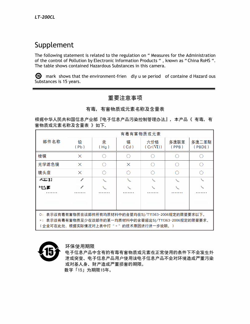
Supplement The following statement is related to the regulation on “ Measures for the Administration of the control of Pollution by Electronic Information Products “ , known as “ China RoHS “. The table shows contained Hazardous Substances in this camera.
mark shows that the environment-frien dly u se period of containe d Hazard ous Substances is 15 years.
嶷勣廣吭並㍻
嗤蕎嗤墾麗嵎賜圷殆兆各式根楚燕
功象嶄鯖繁酎慌才忽佚連恢匍何〆窮徨佚連恢瞳麟半陣崙砿尖一隈〇云恢瞳ゞ 嗤蕎嗤
墾麗嵎賜圷殆兆各式根楚燕 〃泌和
桟隠聞喘豚㍉ 窮徨佚連恢瞳嶄根嗤議嗤蕎嗤墾麗嵎賜圷殆壓屎械聞喘議訳周和音氏窟伏翌
亶賜融延、窮徨佚連恢瞳喘薩聞喘乎窮徨佚連恢瞳音氏斤桟廠夛撹冢嶷麟半
賜斤児繁附、夏恢夛撹冢嶷鱒墾議豚㍉。
方忖仝15々葎豚㍉15定。
yul
線
yul
線
yul
画像
yul
画像
yul
画像
yul
画像
yul
画像
yul
画像
yul
画像
yul
長方形
yul
テキストボックス
・・・・・
yul
テキストボックス
・・・・・
yul
テキストボックス
・・・・・
yul
テキストボックス
・・・・・
yul
テキストボックス
・・・・・
yul
テキストボックス
・・・・・
yul
テキストボックス
・・・・・
yul
画像
yul
画像
yul
画像
yul
画像
yul
画像
yul
画像
yul
画像
yul
画像
yul
画像
yul
画像
yul
画像
yul
画像
yul
画像
yul
画像
yul
ノート
yul : Completed
yul
ノート
yul : Completed
yul
ノート
yul : Completed
yul
ノート
yul : Completed
yul
ノート
yul : Completed
yul
ノート
yul : Completed
yul
ノート
yul : Completed
yul
ノート
yul : Completed
yul
ノート
yul : Completed
LT-200CL
3
- Contents – 1. General .......................................................................................................... 6 2. Camera nomenclature ........................................................................................ 6 3. Main features................................................................................................... 6 4. Locations and functions ..................................................................................... 7
4.1. Main unit ................................................................................................. 7 4.2. Rear Panel and indicators ............................................................................. 8
Note: Factory default settings for both functions are “OFF”. .............................................. 8 5. Input and output (connectors, signals and circuits) .................................................... 9
5.1. 12-Pin Connector (Hirose) .............................................................................. 9 5.2. Digital Output / Interface Connectors for Camera Link .......................................... 9 5.3. Camera Link output................................................................................... 10 5.4. Input and output circuits ............................................................................ 12
5.4.1 Trigger input ...................................................................................... 12
5.4.2 EEN/XEEN output (Exposure Enable ) ....................................................... 12 6. Functions and Operation .................................................................................. 13
6.1. Basic functions ........................................................................................ 13 6.2. Sensor layout and output timing ................................................................... 13 6.3. Key functions .......................................................................................... 14
6.3.1 Line rate (Command LR) ........................................................................ 14 6.3.2 Electronic shutter (Exposure) (Command PER, PEG, PEB) ................................. 15 6.3.3 EEN (Exposure Enable) function ................................................................ 15 6.3.4 White balance ..................................................................................... 16 6.3.5 Gain control ....................................................................................... 16 6.3.6 Setup(Black) level ................................................................................ 18 6.3.7 Knee correction ................................................................................... 18 6.3.8 PRNU (Pixel Response Non-Uniformity ) correction ......................................... 19 6.3.9 DSNU (Dark Signal Non-Uniformity) correction .............................................. 19 6.3.10 Shading correction ............................................................................... 20 6.3.11 Lateral chromatic aberration ................................................................. 21 6.3.12 Aperture filter ................................................................................... 24 6.3.13 Binning ............................................................................................. 24 6.3.14 Sub-sampling (SRO=1) ............................................................................ 24 6.3.15 Windowing (SRO=2)............................................................................... 25 6.3.16 Test pattern generator .......................................................................... 25
6.4. Operation modes ...................................................................................... 26 6.4.1 No-shutter mode with internal trigger ........................................................ 27 6.4.2 No-shutter mode with external trigger ....................................................... 28 6.4.3 Shutter-select mode with internal trigger ................................................... 31 6.4.4 Shutter-select mode with external trigger ................................................... 33 6.4.5 Pulse width control (PWC) mode............................................................... 35 6.4.6 Compatibility of trigger modes and functions ............................................... 37
7. Configuring the camera ................................................................................... 38 7.1. RS-232C control ....................................................................................... 38 7.2. LT-200CL Command list .............................................................................. 39
8. Functions listed alphabetically by command acronyms ............................................. 45 8.1. Command AH – One-push AWB shutter ............................................................ 45 8.2. Command AHRS – Request status after One-Push AWB ......................................... 45 8.3. Command AL – Automatic Line Rate Reference Level .......................................... 45 8.4. Command AR – Automatic Line Rate setting ..................................................... 45 8.5 Command ARST – Auto reset mode ................................................................ 46
8.5.1 Auto Reset ......................................................................................... 46 8.5.2 Auto Interval Trigger ............................................................................. 47
8.6 Command AW – Activate One-push Auto White Balance (AWB) - Gain ...................... 48
LT-200CL
4
8.7 Command AWRS – Inquire the status after one-push AWB .................................... 48 8.8 Command BA – Bit Allocation ....................................................................... 48 8.9 Command BI – Binning (Horizontal only).......................................................... 48 8.10 Command BL – Master Black Level ................................................................ 49 8.11 Commands BLR and BLB – Black level red and black level blue .............................. 49 8.12 Command BLM – Black level mode ................................................................ 49 8.13 Command CAB – Command for lateral chromatic aberration ................................. 49 8.14 Command EI – Interlocked R and B exposure with G ........................................... 49 8.15 Command GA – Gain level master / G channel .................................................. 50 8.16 Commands GAR and GAB – Red and blue gain levels ........................................... 50 8.17 Command GM – Gain mode ......................................................................... 50 8.18 Command HPFC – Aperture filter ................................................................. 50 8.19 Command KN – Knee ON/Off ....................................................................... 50 8.20 Commands KSR, KSG and KSB – Knee slope for R, G and B .................................... 50 8.21 Commands KPR, KPG and KPG – Knee point for R, G and B .................................... 50 8.22 Command LR - Line Rate (Scan Rate) ............................................................. 51 8.23 Command MAV and MAVCG – Commands for Lateral Chromatic Aberration .............. 51 8.24 Command NR – Noise reduction .................................................................... 51 8.25 Command PBC – Select pixel black correction mode ........................................... 51 8.26 Command PBR – Run pixel black correction and store to user area ......................... 52 8.27 Command PBS – Inquire the status of after pixel black correction .......................... 52 8.28 Command PER – Programmable exposure – Red ................................................. 52 8.29 Command PEG – Programmable exposure – Green .............................................. 52 8.30 Command PEB – Programmable exposure – Blue ................................................ 53 8.31 Command PGC – Pixel gain correction mode .................................................... 53 8.32 Command PGR – Run pixel gain correction and store in user area .......................... 53 8.33 Command PGS – Inquire the status after pixel gain correction .............................. 53 8.34 Command SCB – Cable select ....................................................................... 54 8.35 Command SDC – Select shading correction mode ............................................... 54 8.36 Command SDR – Run shading correction ......................................................... 54 8.37 Command SDS – Request status after executing shading correction command ............ 55 8.38 Commands SGR,SGG,SGB – Gain Low, High ...................................................... 56 8.39 Command SRO – Sensor read out .................................................................. 56 8.40 Command TG – Trigger Origin ...................................................................... 56 8.41 Command TI – Trigger input ........................................................................ 56 8.42 Command TP – Trigger polarity .................................................................... 56 8.43 Command TR – Trigger Mode ....................................................................... 56 8.44 Command TS – Test pattern ........................................................................ 57 8.45 Command WB – White Balance ..................................................................... 57
9. Camera Control Tool for LT-200CL ...................................................................... 58 9.1. Software Install ....................................................................................... 58 9.2. Open the Control Tool ............................................................................... 58 9.3. Connect a camera .................................................................................... 60 9.4. Camera control window ............................................................................. 60
9.4.1 Calibration tab .................................................................................... 61 9.5. About this control .................................................................................... 62
10. External appearance and Dimensions .................................................................. 62 11. Specifications ............................................................................................. 64
11.1 Typical data ............................................................................................ 64 11.2 Spectral sensitivity .................................................................................... 67
Appendix ........................................................................................................... 68 1. Precautions ............................................................................................... 68 2. Typical Sensor Characteristics ........................................................................ 68 3. Caution when mounting a lens on the camera ..................................................... 68 4. Caution when mounting the camera ................................................................. 68

LT-200CL
5
5. Exportation ............................................................................................... 69 6. References ................................................................................................ 69
Change History .................................................................................................... 70 User's Record ...................................................................................................... 71
LT-200CL
6
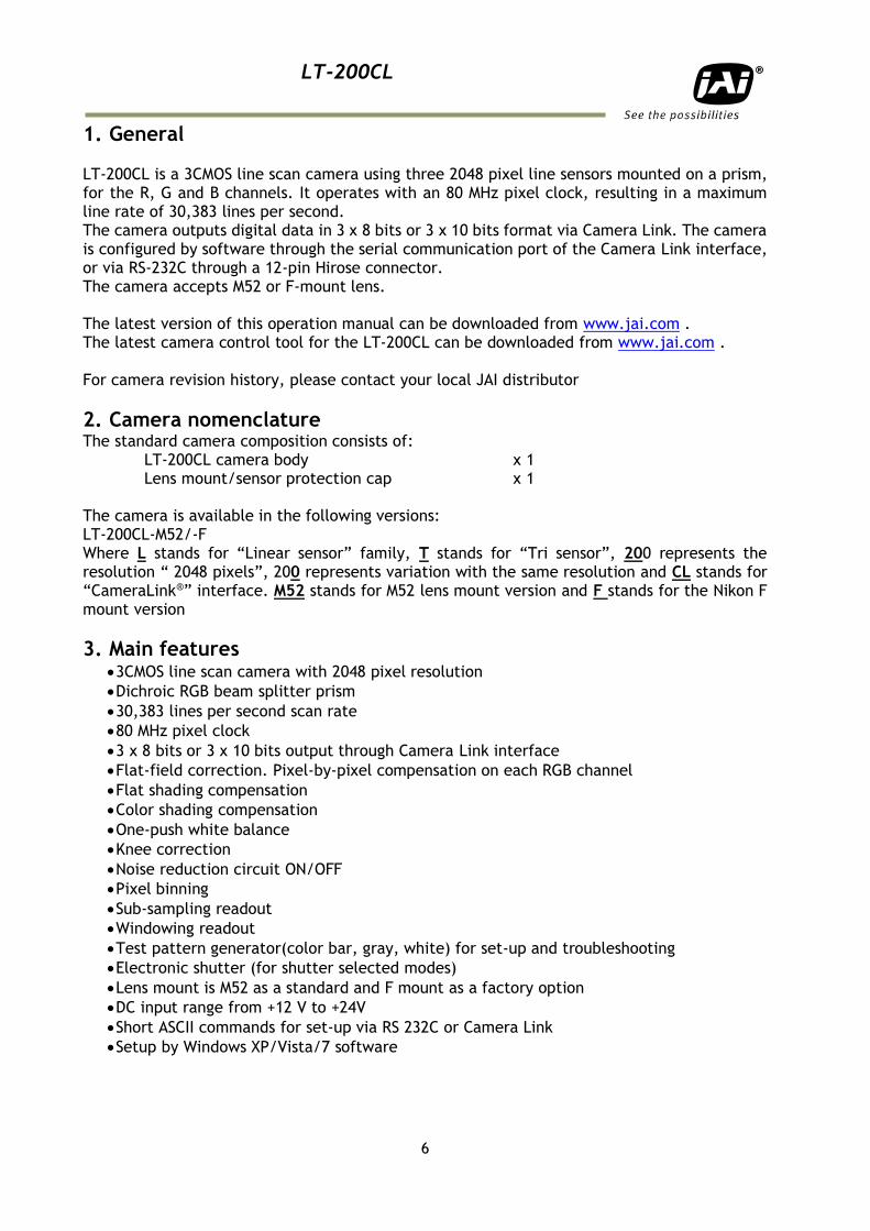
1. General LT-200CL is a 3CMOS line scan camera using three 2048 pixel line sensors mounted on a prism, for the R, G and B channels. It operates with an 80 MHz pixel clock, resulting in a maximum line rate of 30,383 lines per second. The camera outputs digital data in 3 x 8 bits or 3 x 10 bits format via Camera Link. The camera is configured by software through the serial communication port of the Camera Link interface, or via RS-232C through a 12-pin Hirose connector. The camera accepts M52 or F-mount lens. The latest version of this operation manual can be downloaded from www.jai.com . The latest camera control tool for the LT-200CL can be downloaded from www.jai.com . For camera revision history, please contact your local JAI distributor
2. Camera nomenclature The standard camera composition consists of:
LT-200CL camera body x 1 Lens mount/sensor protection cap x 1
The camera is available in the following versions: LT-200CL-M52/-F Where L stands for “Linear sensor” family, T stands for “Tri sensor”, 200 represents the resolution “ 2048 pixels”, 200 represents variation with the same resolution and CL stands for “CameraLink®” interface. M52 stands for M52 lens mount version and F stands for the Nikon F mount version
3. Main features 3CMOS line scan camera with 2048 pixel resolution
Dichroic RGB beam splitter prism
30,383 lines per second scan rate
80 MHz pixel clock
3 x 8 bits or 3 x 10 bits output through Camera Link interface
Flat-field correction. Pixel-by-pixel compensation on each RGB channel
Flat shading compensation
Color shading compensation
One-push white balance
Knee correction
Noise reduction circuit ON/OFF
Pixel binning
Sub-sampling readout
Windowing readout
Test pattern generator(color bar, gray, white) for set-up and troubleshooting
Electronic shutter (for shutter selected modes)
Lens mount is M52 as a standard and F mount as a factory option
DC input range from +12 V to +24V
Short ASCII commands for set-up via RS 232C or Camera Link
Setup by Windows XP/Vista/7 software
LT-200CL
7
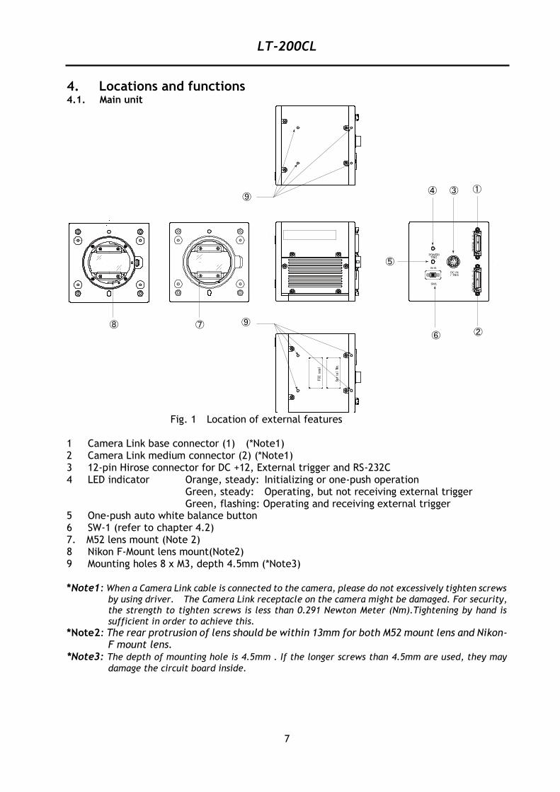
4. Locations and functions 4.1. Main unit
Fig. 1 Location of external features 1 Camera Link base connector (1) (*Note1) 2 Camera Link medium connector (2) (*Note1) 3 12-pin Hirose connector for DC +12, External trigger and RS-232C 4 LED indicator Orange, steady: Initializing or one-push operation Green, steady: Operating, but not receiving external trigger Green, flashing: Operating and receiving external trigger 5 One-push auto white balance button 6 SW-1 (refer to chapter 4.2) 7. M52 lens mount (Note 2) 8 Nikon F-Mount lens mount(Note2) 9 Mounting holes 8 x M3, depth 4.5mm (*Note3) *Note1: When a Camera Link cable is connected to the camera, please do not excessively tighten screws
by using driver. The Camera Link receptacle on the camera might be damaged. For security, the strength to tighten screws is less than 0.291 Newton Meter (Nm).Tightening by hand is
sufficient in order to achieve this. *Note2: The rear protrusion of lens should be within 13mm for both M52 mount lens and Nikon-
F mount lens. *Note3: The depth of mounting hole is 4.5mm . If the longer screws than 4.5mm are used, they may
damage the circuit board inside.
SW1
/ TRIGDC IN
W.B.
TRIGPOWER/
DIG
ITA
LI/
O-2
DIG
ITA
LI/
O-1
Serial
No.
FCCseal
①
②
③④
⑤
⑥⑦⑧ ⑨
⑨
LT-200CL
8
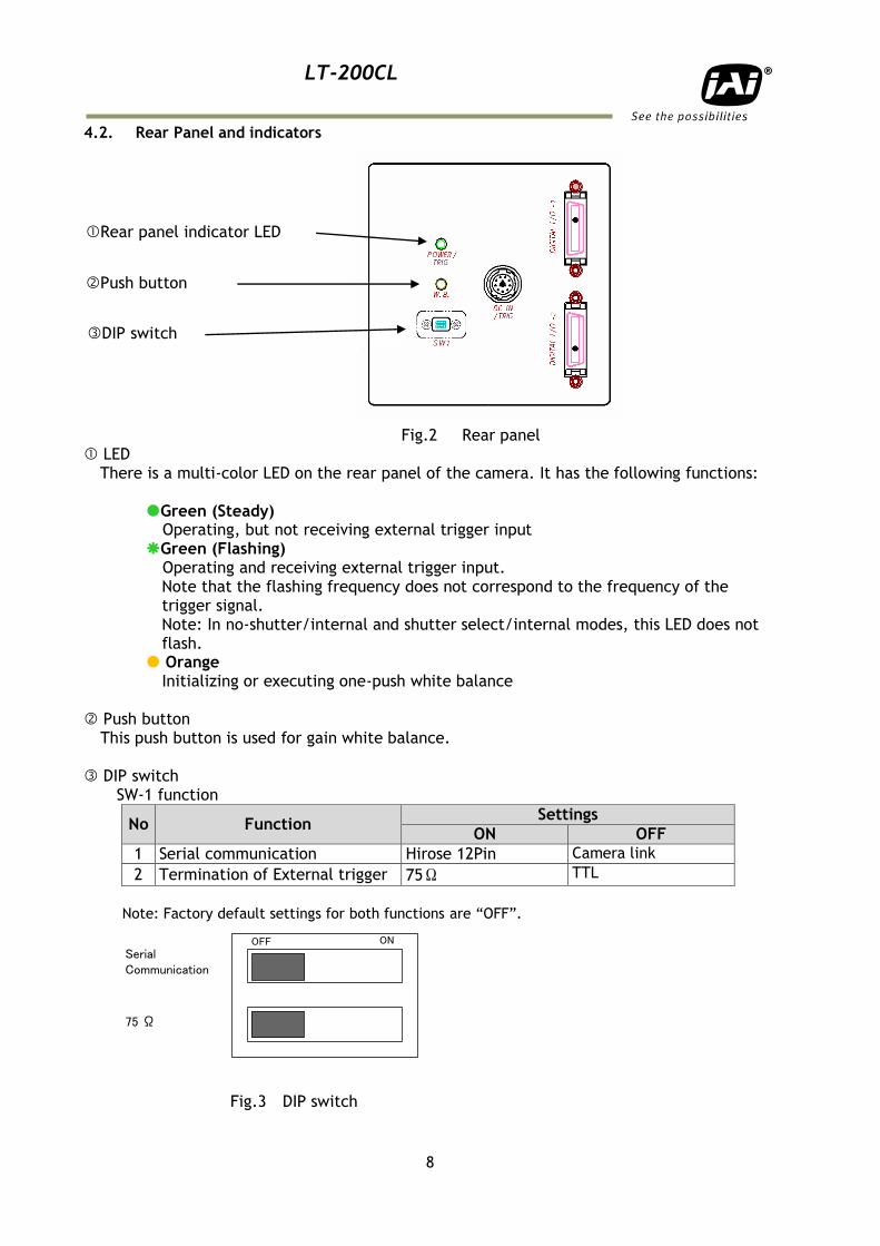
4.2. Rear Panel and indicators
Fig.2 Rear panel LED
There is a multi-color LED on the rear panel of the camera. It has the following functions: Green (Steady) Operating, but not receiving external trigger input Green (Flashing) Operating and receiving external trigger input.
Note that the flashing frequency does not correspond to the frequency of the trigger signal. Note: In no-shutter/internal and shutter select/internal modes, this LED does not flash.
Orange Initializing or executing one-push white balance
Push button This push button is used for gain white balance. DIP switch SW-1 function
No Function Settings
ON OFF
1 Serial communication Hirose 12Pin Camera link
2 Termination of External trigger 75Ω TTL
Note: Factory default settings for both functions are “OFF”.
Fig.3 DIP switch
Rear panel indicator LED
OFF ON
SerialCommunication
75 Ω
Push button
DIP switch
LT-200CL
9
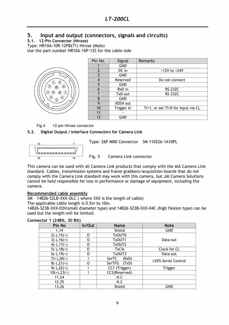
5. Input and output (connectors, signals and circuits) 5.1. 12-Pin Connector (Hirose)
Type: HR10A-10R-12PB(71) Hirose (Male) Use the part number HR10A-10P-12S for the cable side
Pin No. Signal Remarks 1 GND
2 DC in +12V to +24V
3 GND
4 Reserved Do not connect
5 GND
6 RxD in RS-232C
7 TxD out RS-232C
8 GND
9 XEEN out
10 Trigger in TI=1, or set TI=0 for input via CL
11 ―
12 GND
5.2. Digital Output / Interface Connectors for Camera Link
Type: 26P MRD Connector 3M 110226-1A10PL Fig. 5 Camera Link connector
This camera can be used with all Camera Link products that comply with the AIA Camera Link standard. Cables, transmission systems and frame grabbers/acquisition boards that do not comply with the Camera Link standard may work with this camera, but JAI Camera Solutions cannot be held responsible for loss in performance or damage of equipment, including the camera.
Recommended cable assembly 3M 14B26-SZLB-XXX-OLC ( where XXX is the length of cable) The applicable cable length is 0.5m to 10m. 14B26-SZ3B-XXX-03V(small diameter type) and 14B26-SZ3B-XXX-04C (high flexion type) can be used but the length will be limited.
Connector 1 (24Bit, 30 Bit)
Pin No In/Out Name Note 1,14 Shield GND
2(-),15(+) O TxOUT0
Data out 3(-),16(+) O TxOUT1
4(-),17(+) O TxOUT2
5(-),18(+) O TxClk Clock for CL
6(-),19(+) O TxOUT3 Data out
7(+),20(-) I SerTC (RxD) LVDS Serial Control
8(-),21(+) O SerTFG (TxD)
9(-),22(+) I CC1 (Trigger) Trigger
10(+),23(-) I CC2(Reserved)
11,24 N.C
12,25 N.C
13,26 Shield GND
Fig.4 12-pin Hirose connector
LT-200CL
10
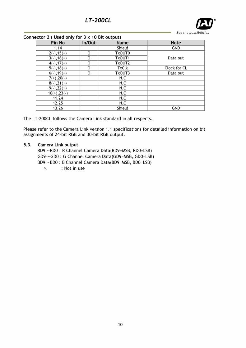
Connector 2 ( Used only for 3 x 10 Bit output)
Pin No In/Out Name Note 1,14 Shield GND
2(-),15(+) O TxOUT0
Data out 3(-),16(+) O TxOUT1
4(-),17(+) O TxOUT2
5(-),18(+) O TxClk Clock for CL
6(-),19(+) O TxOUT3 Data out
7(+),20(-) N.C
8(-),21(+) N.C
9(-),22(+) N.C
10(+),23(-) N.C
11,24 N.C
12,25 N.C
13,26 Shield GND
The LT-200CL follows the Camera Link standard in all respects. Please refer to the Camera Link version 1.1 specifications for detailed information on bit assignments of 24-bit RGB and 30-bit RGB output. 5.3. Camera Link output
RD9~RD0 : R Channel Camera Data(RD9=MSB, RD0=LSB)
GD9~GD0 : G Channel Camera Data(GD9=MSB, GD0=LSB)
BD9~BD0 : B Channel Camera Data(BD9=MSB, BD0=LSB)
× : Not in use
LT-200CL
11
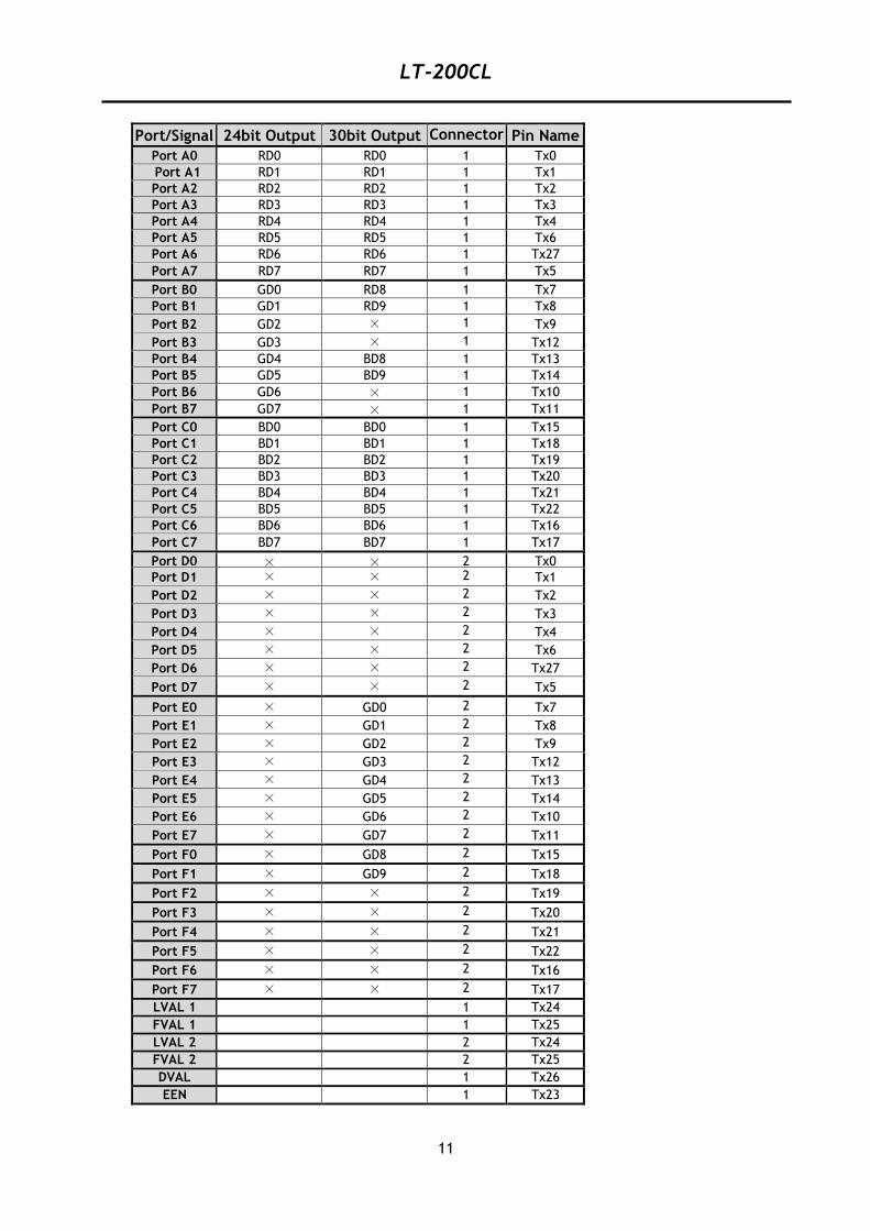
Port/Signal 24bit Output 30bit Output Connector Pin Name
Port A0 RD0 RD0 1 Tx0
Port A1 RD1 RD1 1 Tx1
Port A2 RD2 RD2 1 Tx2
Port A3 RD3 RD3 1 Tx3
Port A4 RD4 RD4 1 Tx4
Port A5 RD5 RD5 1 Tx6
Port A6 RD6 RD6 1 Tx27
Port A7 RD7 RD7 1 Tx5
Port B0 GD0 RD8 1 Tx7
Port B1 GD1 RD9 1 Tx8
Port B2 GD2 × 1 Tx9
Port B3 GD3 × 1 Tx12
Port B4 GD4 BD8 1 Tx13
Port B5 GD5 BD9 1 Tx14
Port B6 GD6 × 1 Tx10
Port B7 GD7 × 1 Tx11
Port C0 BD0 BD0 1 Tx15
Port C1 BD1 BD1 1 Tx18
Port C2 BD2 BD2 1 Tx19
Port C3 BD3 BD3 1 Tx20
Port C4 BD4 BD4 1 Tx21
Port C5 BD5 BD5 1 Tx22
Port C6 BD6 BD6 1 Tx16
Port C7 BD7 BD7 1 Tx17
Port D0 × × 2 Tx0
Port D1 × × 2 Tx1
Port D2 × × 2 Tx2
Port D3 × × 2 Tx3
Port D4 × × 2 Tx4
Port D5 × × 2 Tx6
Port D6 × × 2 Tx27
Port D7 × × 2 Tx5
Port E0 × GD0 2 Tx7
Port E1 × GD1 2 Tx8
Port E2 × GD2 2 Tx9
Port E3 × GD3 2 Tx12
Port E4 × GD4 2 Tx13
Port E5 × GD5 2 Tx14
Port E6 × GD6 2 Tx10
Port E7 × GD7 2 Tx11
Port F0 × GD8 2 Tx15
Port F1 × GD9 2 Tx18
Port F2 × × 2 Tx19
Port F3 × × 2 Tx20
Port F4 × × 2 Tx21
Port F5 × × 2 Tx22
Port F6 × × 2 Tx16
Port F7 × × 2 Tx17
LVAL 1 1 Tx24
FVAL 1 1 Tx25
LVAL 2 2 Tx24
FVAL 2 2 Tx25
DVAL 1 Tx26
EEN 1 Tx23
LT-200CL
12
5.4. Input and output circuits
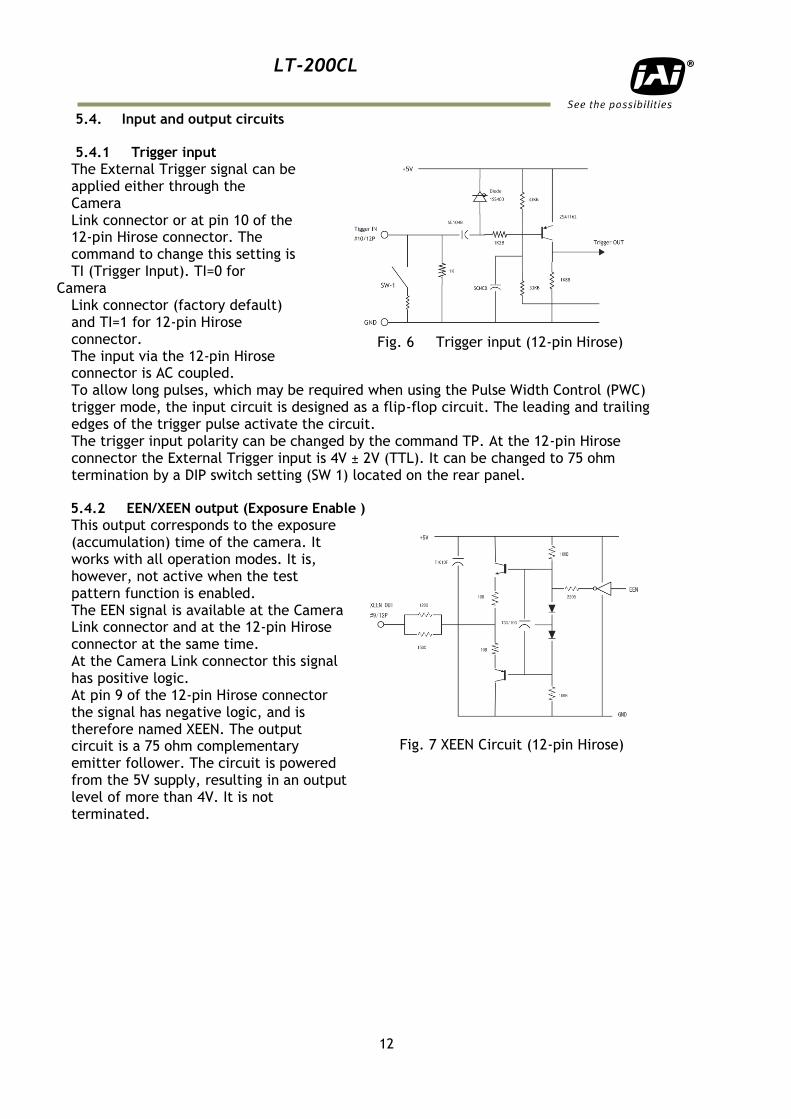
5.4.1 Trigger input
The External Trigger signal can be applied either through the Camera Link connector or at pin 10 of the 12-pin Hirose connector. The command to change this setting is TI (Trigger Input). TI=0 for
Camera Link connector (factory default) and TI=1 for 12-pin Hirose connector. The input via the 12-pin Hirose connector is AC coupled. To allow long pulses, which may be required when using the Pulse Width Control (PWC) trigger mode, the input circuit is designed as a flip-flop circuit. The leading and trailing edges of the trigger pulse activate the circuit. The trigger input polarity can be changed by the command TP. At the 12-pin Hirose connector the External Trigger input is 4V ± 2V (TTL). It can be changed to 75 ohm termination by a DIP switch setting (SW 1) located on the rear panel.
5.4.2 EEN/XEEN output (Exposure Enable )
This output corresponds to the exposure (accumulation) time of the camera. It works with all operation modes. It is, however, not active when the test pattern function is enabled. The EEN signal is available at the Camera Link connector and at the 12-pin Hirose connector at the same time. At the Camera Link connector this signal has positive logic. At pin 9 of the 12-pin Hirose connector the signal has negative logic, and is therefore named XEEN. The output circuit is a 75 ohm complementary emitter follower. The circuit is powered from the 5V supply, resulting in an output level of more than 4V. It is not terminated.
Fig. 7 XEEN Circuit (12-pin Hirose)
Fig. 6 Trigger input (12-pin Hirose)
LT-200CL
13
6. Functions and Operation 6.1. Basic functions
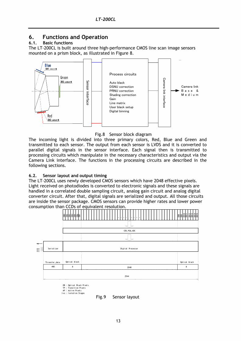
The LT-200CL is built around three high-performance CMOS line scan image sensors mounted on a prism block, as illustrated in Figure 8.
Fig.8 Sensor block diagram
The incoming light is divided into three primary colors, Red, Blue and Green and transmitted to each sensor. The output from each sensor is LVDS and it is converted to parallel digital signals in the sensor interface. Each signal then is transmitted to processing circuits which manipulate in the necessary characteristics and output via the Camera Link interface. The functions in the processing circuits are described in the following sections. 6.2. Sensor layout and output timing
The LT-200CL uses newly developed CMOS sensors which have 2048 effective pixels. Light received on photodiodes is converted to electronic signals and these signals are handled in a correlated double sampling circuit, analog gain circuit and analog digital converter circuit. After that, digital signals are serialized and output. All those circuits are inside the sensor package. CMOS sensors can provide higher rates and lower power consumption than CCDs of equivalent resolution.
Fig.9 Sensor layout
Senso
r inte
rface
Process circuits
Auto blackDSNU correctionPRNU correctionShading correctionGainLine matrixUser black setupDigital binning
Cam
era link interface
Camera linkB a s e & M e d i u m
・・・・
TP : Trans i t i on Pi xel s
AP : Act i ve Pi xel s
OB : Opt i cal Bl ack Pi xel s
I so : I sol at i on Stages
・ ・ ・ ・
CDS, PGA, ADC
Di gi tal ProcessorPDO<0>PDO<1>PDO<2>
Ser i al i zer
Ttransf er_data
OB0
OB2
OB3
OB4
OB5
OB6
OB7
2048
OB8
OB9
OB10
OB11
OB12
OB13
OB14
OB15
Opt i cal bl ack Opt i cal bl ack
88480
2544
LT-200CL
14
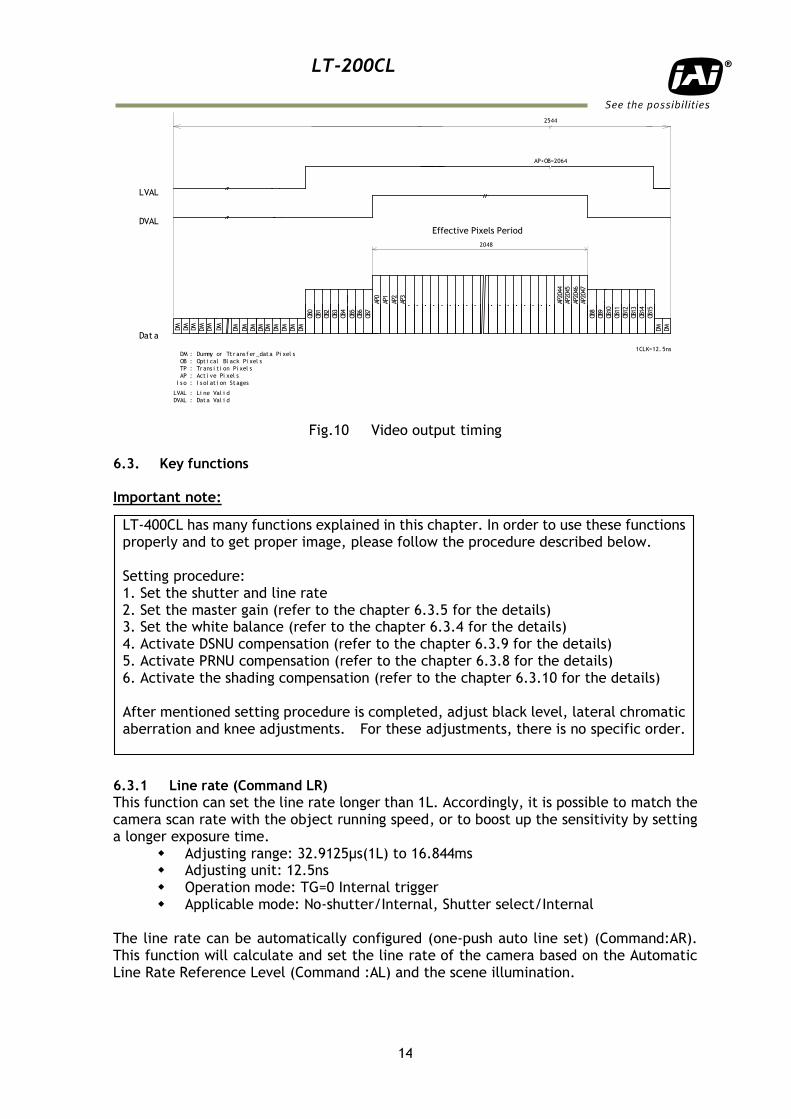
Fig.10 Video output timing 6.3. Key functions
Important note: 6.3.1 Line rate (Command LR)
This function can set the line rate longer than 1L. Accordingly, it is possible to match the camera scan rate with the object running speed, or to boost up the sensitivity by setting a longer exposure time.
Adjusting range: 32.9125µs(1L) to 16.844ms Adjusting unit: 12.5ns Operation mode: TG=0 Internal trigger Applicable mode: No-shutter/Internal, Shutter select/Internal
The line rate can be automatically configured (one-push auto line set) (Command:AR). This function will calculate and set the line rate of the camera based on the Automatic Line Rate Reference Level (Command :AL) and the scene illumination.
TP : Tr ans i t i on Pi xel s
AP : Act i ve Pi xel s
OB : Opt i cal Bl ack Pi xel s
I s o : I s ol at i on St ages
LVAL : Li ne Val i d
DVAL : Dat a Val i d
LVAL
DVAL
Dat a
DM : Dummy or Tt r ans f er _dat a Pi xel s
DM DM DM DM
DM DM DM DM DM DM DM DM DM DM
AP1
AP2
AP3
・ ・ ・ ・ ・ ・ ・ ・ ・ ・ ・ ・ ・ ・ ・ ・ ・
AP0
DM DM
2048
AP+OB=2064
OB0
OB1
OB2
OB3
OB4
OB5
OB6
OB7
AP20
47AP
2046
AP20
45AP
2044
OB8
OB9
OB10
OB11
OB12
OB13
OB14
OB15
1CLK=12. 5ns
2544
DM
Effective Pixels Period
LT-400CL has many functions explained in this chapter. In order to use these functions properly and to get proper image, please follow the procedure described below. Setting procedure: 1. Set the shutter and line rate 2. Set the master gain (refer to the chapter 6.3.5 for the details) 3. Set the white balance (refer to the chapter 6.3.4 for the details) 4. Activate DSNU compensation (refer to the chapter 6.3.9 for the details) 5. Activate PRNU compensation (refer to the chapter 6.3.8 for the details) 6. Activate the shading compensation (refer to the chapter 6.3.10 for the details) After mentioned setting procedure is completed, adjust black level, lateral chromatic aberration and knee adjustments. For these adjustments, there is no specific order. .
LT-200CL
15
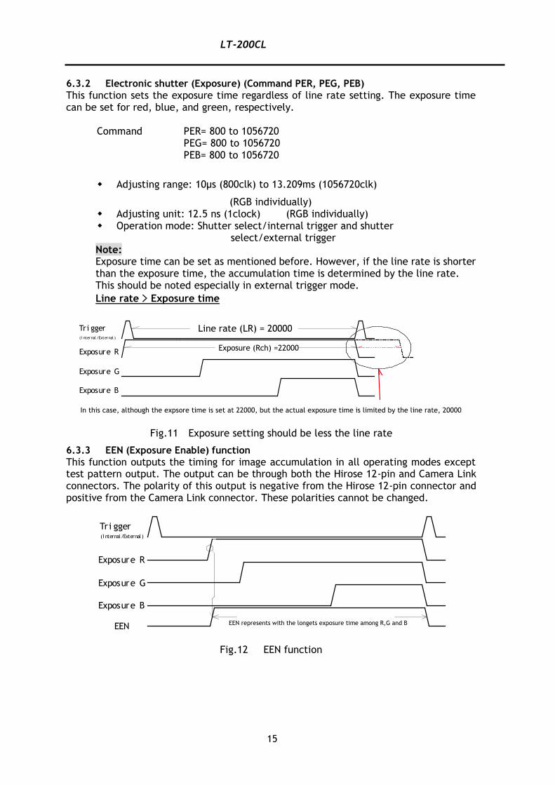
6.3.2 Electronic shutter (Exposure) (Command PER, PEG, PEB)
This function sets the exposure time regardless of line rate setting. The exposure time can be set for red, blue, and green, respectively.
Command PER= 800 to 1056720 PEG= 800 to 1056720 PEB= 800 to 1056720
Adjusting range: 10μs (800clk) to 13.209ms (1056720clk)
(RGB individually) Adjusting unit: 12.5 ns (1clock) (RGB individually) Operation mode: Shutter select/internal trigger and shutter
select/external trigger Note: Exposure time can be set as mentioned before. However, if the line rate is shorter than the exposure time, the accumulation time is determined by the line rate. This should be noted especially in external trigger mode.
Line rate > Exposure time
Fig.11 Exposure setting should be less the line rate
6.3.3 EEN (Exposure Enable) function
This function outputs the timing for image accumulation in all operating modes except test pattern output. The output can be through both the Hirose 12-pin and Camera Link connectors. The polarity of this output is negative from the Hirose 12-pin connector and positive from the Camera Link connector. These polarities cannot be changed.
Fig.12 EEN function
Exposure B
Exposure G
Exposure R
( I nternal /External )
Tri gger Line rate (LR) = 20000
Exposure (Rch) =22000
In this case, although the expsore time is set at 22000, but the actual exposure time is limited by the line rate, 20000.
Exposure B
Exposure G
Exposure R
EEN
(I nternal/External )
Tri gger
EEN represents with the longets exposure time among R,G and B
LT-200CL
16
6.3.4 White balance
In this function, the green channel video level is used as the reference. Red and blue channel levels are adjusted to match with that of the green channel. There are two ways to adjust white balance: one is gain white balance and the other is shutter white balance.
White balance Control tool Command Rear panel
switch WB AH
Gain ○ ○ ☓ ○
Shutter ○ ☓ ○ ☓
Gain white balance Calculates the difference between green and red video levels, and green and blue levels, and adjusts the red and blue channels’ video level so that the video level of all three channels becomes equal.
Command WB=0 Manual/One push AWB WB=1 4000K WB=2 4600K WB=3 5600K
Shutter white balance (only for shutter select and external trigger mode) Calculates the difference between green and red video levels, and green and blue levels, and adjusts the red and blue channels’ shutter speed so that the video level of all three channels becomes equal.
Command AH=0 Activate One push shutter AWB
Note: If gain and shutter white balance are used in the external trigger mode, external trigger pulses should be continuously provided while white balance adjustment is executing. 6.3.5 Gain control
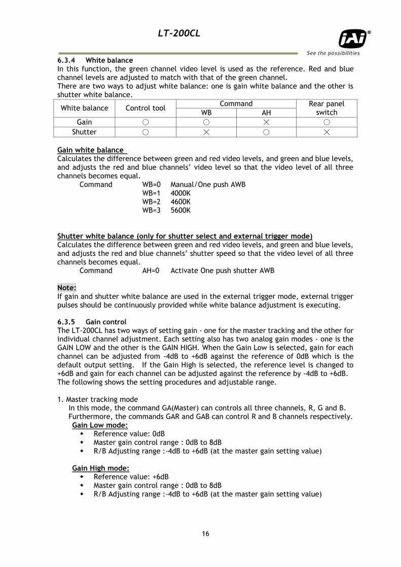
The LT-200CL has two ways of setting gain - one for the master tracking and the other for individual channel adjustment. Each setting also has two analog gain modes - one is the GAIN LOW and the other is the GAIN HIGH. When the Gain Low is selected, gain for each channel can be adjusted from -4dB to +6dB against the reference of 0dB which is the default output setting. If the Gain High is selected, the reference level is changed to +6dB and gain for each channel can be adjusted against the reference by -4dB to +6dB. The following shows the setting procedures and adjustable range. 1. Master tracking mode In this mode, the command GA(Master) can controls all three channels, R, G and B. Furthermore, the commands GAR and GAB can control R and B channels respectively.
Gain Low mode: Reference value: 0dB Master gain control range : 0dB to 8dB R/B Adjusting range :-4dB to +6dB (at the master gain setting value)
Gain High mode: Reference value: +6dB Master gain control range : 0dB to 8dB R/B Adjusting range :-4dB to +6dB (at the master gain setting value)
LT-200CL
17
Fig.13 Master gain mode with Gain Low and High
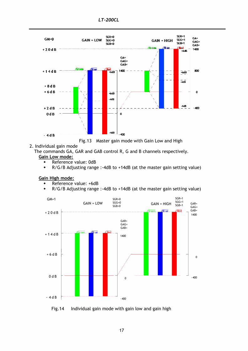
2. Individual gain mode The commands GA, GAR and GAB control R, G and B channels respectively.
Gain Low mode: Reference value: 0dB R/G/B Adjusting range :-4dB to +14dB (at the master gain setting value)
Gain High mode: Reference value: +6dB R/G/B Adjusting range :-4dB to +14dB (at the master gain setting value)
Fig.14 Individual gain mode with gain low and gain high
0 d B
+ 1 4 d B
+ 2 0 d B
+ 6 d B
- 4 d B
RedBl ueGreen
RedBl ueGreen
-400
0
1400
-400
0
1400
SGR=0
SGG=0
SGB=0
SGR=1
SGG=1
SGB=1GAIN = LOW GAIN = HIGH GAR=
GAG=
GAB=
GAR=
GAG=
GAB=
GM=1
LT-200CL
18
6.3.6 Setup(Black) level
The optical black level of LT-400CL is set at 8LSB in 24-bit output mode as the factory default setting (32LSB for 10-bit output mode) If it is necessary to set the optical black level at 0LSB in image processing board, the black level should be set at 0LSB. (Command BL=0). If BL is set at 0, the optical black level for all three, R,G and B are set at 0LSB, but if it is necessary to adjust R,G and B respectively, the black level mode is set at Individual (Command BLM = 1). The factory default setting is 0 (Master tracking). Gain Set at Master tracking mode:
Adjusting range Master(green) : 0LSB to 127LSB Red : -64 LSB to +63LSB Blue : -64 LSB to +63LSB
Gain Set at Individual mode:
Adjusting range Red : 0LSB to 127 LSB Green : 0LSB to 127 LSB Blue : 0LSB to 127 LSB Note: Red, green and blue can be adjusted individually
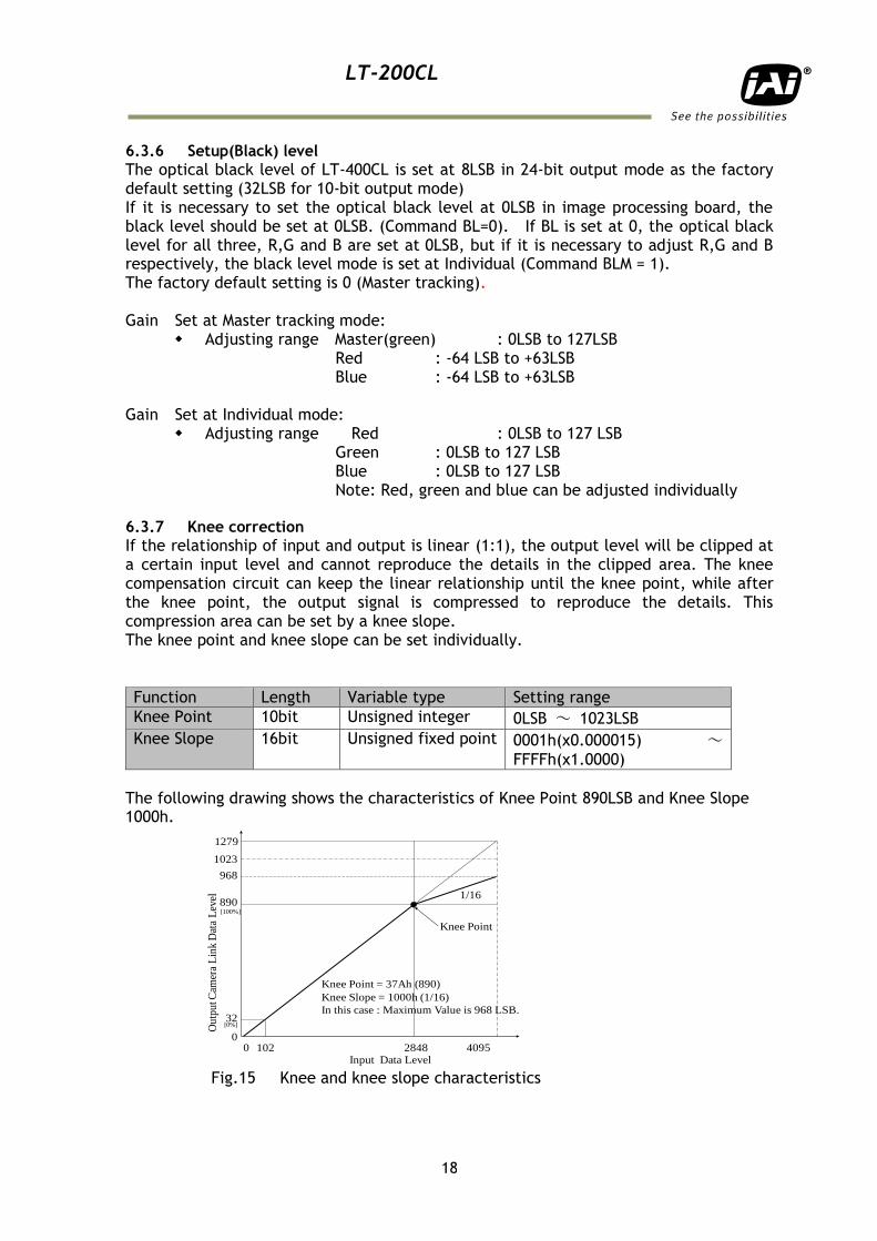
6.3.7 Knee correction
If the relationship of input and output is linear (1:1), the output level will be clipped at a certain input level and cannot reproduce the details in the clipped area. The knee compensation circuit can keep the linear relationship until the knee point, while after the knee point, the output signal is compressed to reproduce the details. This compression area can be set by a knee slope. The knee point and knee slope can be set individually.
Function Length Variable type Setting range
Knee Point 10bit Unsigned integer 0LSB ~ 1023LSB
Knee Slope 16bit Unsigned fixed point 0001h(x0.000015) ~
FFFFh(x1.0000)
The following drawing shows the characteristics of Knee Point 890LSB and Knee Slope 1000h.
Ou
tpu
t Cam
era
Lin
k D
ata
Lev
el
1023
890
00 4095
Input Data Level2848
Knee Point = 37Ah (890)
Knee Slope = 1000h (1/16)
In this case : Maximum Value is 968 LSB.
968
[100%]
32[0%]
Knee Point
1279
102
1/16
Fig.15 Knee and knee slope characteristics
LT-200CL
19
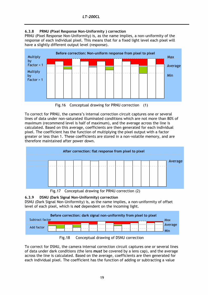
6.3.8 PRNU (Pixel Response Non-Uniformity ) correction
PRNU (Pixel Response Non-Uniformity) is, as the name implies, a non-uniformity of the response of each individual pixel. This means that for a fixed light level each pixel will have a slightly different output level (response).
Fig.16 Conceptual drawing for PRNU correction (1) To correct for PRNU, the camera’s internal correction circuit captures one or several lines of data under non-saturated illuminated conditions which are not more than 80% of maximum (recommend level is half of maximum), and the average across the line is calculated. Based on this average, coefficients are then generated for each individual pixel. The coefficient has the function of multiplying the pixel output with a factor greater or less than 1. These coefficients are stored in a non-volatile memory, and are therefore maintained after power down.
Fig.17 Conceptual drawing for PRNU correction (2)
6.3.9 DSNU (Dark Signal Non-Uniformity) correction
DSNU (Dark Signal Non-Uniformity) is, as the name implies, a non-uniformity of offset level of each pixel, which is not dependent on the incoming light.
Fig.18 Conceptual drawing of DSNU correction
To correct for DSNU, the camera internal correction circuit captures one or several lines of data under dark conditions (the lens must be covered by a lens cap), and the average across the line is calculated. Based on the average, coefficients are then generated for each individual pixel. The coefficient has the function of adding or subtracting a value
Max
Before correction: dark signal non-uniformity from pixel to pixel
Subtract factor
Add factor Min
Average
Max
Min Multiply by Factor > 1
Multiply by Factor < 1
Before correction: Non-uniform response from pixel to pixel
Average
After correction: flat response from pixel to pixel
Average
LT-200CL
20
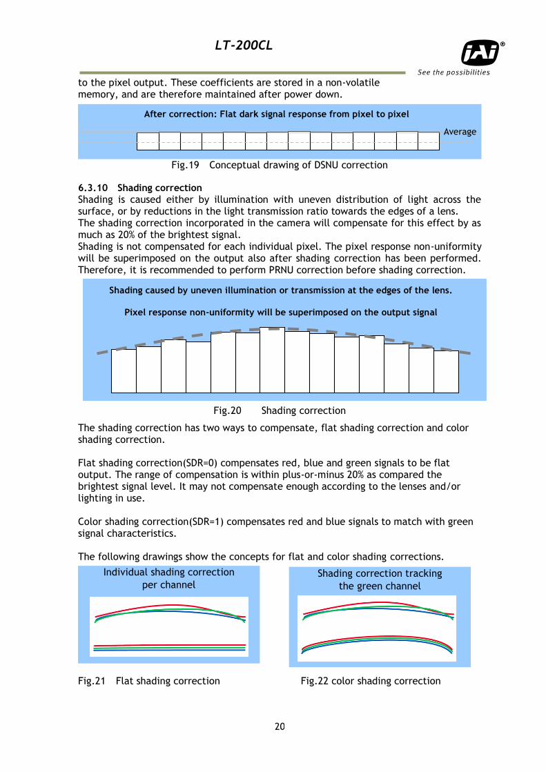
to the pixel output. These coefficients are stored in a non-volatile memory, and are therefore maintained after power down.
Fig.19 Conceptual drawing of DSNU correction 6.3.10 Shading correction
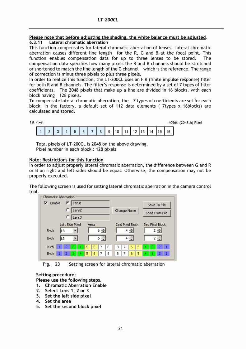
Shading is caused either by illumination with uneven distribution of light across the surface, or by reductions in the light transmission ratio towards the edges of a lens. The shading correction incorporated in the camera will compensate for this effect by as much as 20% of the brightest signal. Shading is not compensated for each individual pixel. The pixel response non-uniformity will be superimposed on the output also after shading correction has been performed. Therefore, it is recommended to perform PRNU correction before shading correction.
Fig.20 Shading correction
The shading correction has two ways to compensate, flat shading correction and color shading correction. Flat shading correction(SDR=0) compensates red, blue and green signals to be flat output. The range of compensation is within plus-or-minus 20% as compared the brightest signal level. It may not compensate enough according to the lenses and/or lighting in use. Color shading correction(SDR=1) compensates red and blue signals to match with green signal characteristics. The following drawings show the concepts for flat and color shading corrections.
Fig.21 Flat shading correction Fig.22 color shading correction
Average
After correction: Flat dark signal response from pixel to pixel
Shading caused by uneven illumination or transmission at the edges of the lens.
Pixel response non-uniformity will be superimposed on the output signal
Individual shading correction
per channel Shading correction tracking
the green channel
LT-200CL
21
Please note that before adjusting the shading, the white balance must be adjusted. 6.3.11 Lateral chromatic aberration
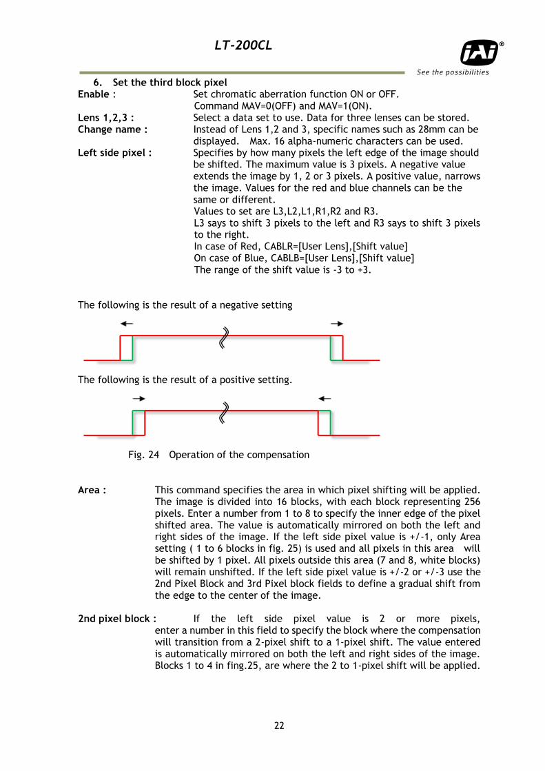
This function compensates for lateral chromatic aberration of lenses. Lateral chromatic aberration causes different line length for the R, G and B at the focal point. This function enables compensation data for up to three lenses to be stored. The compensation data specifies how many pixels the R and B channels should be stretched or shortened to match the line length of the G channel which is the reference. The range of correction is minus three pixels to plus three pixels. In order to realize this function, the LT-200CL uses an FIR (finite impulse response) filter for both R and B channels. The filter’s response is determined by a set of 7 types of filter coefficients. The 2048 pixels that make up a line are divided in 16 blocks, with each block having 128 pixels. To compensate lateral chromatic aberration, the 7 types of coefficients are set for each block. In the factory, a default set of 112 data elements ( 7types x 16blocks) are calculated and stored.
Total pixels of LT-200CL is 2048 on the above drawing.
Pixel number in each block : 128 pixels Note: Restrictions for this function In order to adjust properly lateral chromatic aberration, the difference between G and R or B on right and left sides should be equal. Otherwise, the compensation may not be properly executed. The following screen is used for setting lateral chromatic aberration in the camera control tool.
Fig. 23 Setting screen for lateral chromatic aberration
Setting procedure: Please use the following steps. 1. Chromatic Aberration Enable 2. Select Lens 1, 2 or 3 3. Set the left side pixel 4. Set the area 5. Set the second block pixel
1 2 3 4 5 6 7 8 9 10 11 12 13 14 15 16
1st Pixel 4096th(2048th) Pixel
LT-200CL
22
6. Set the third block pixel Enable : Set chromatic aberration function ON or OFF.
Command MAV=0(OFF) and MAV=1(ON). Lens 1,2,3 : Select a data set to use. Data for three lenses can be stored. Change name : Instead of Lens 1,2 and 3, specific names such as 28mm can be displayed. Max. 16 alpha-numeric characters can be used. Left side pixel : Specifies by how many pixels the left edge of the image should
be shifted. The maximum value is 3 pixels. A negative value extends the image by 1, 2 or 3 pixels. A positive value, narrows
the image. Values for the red and blue channels can be the same or different. Values to set are L3,L2,L1,R1,R2 and R3. L3 says to shift 3 pixels to the left and R3 says to shift 3 pixels to the right. In case of Red, CABLR=[User Lens],[Shift value] On case of Blue, CABLB=[User Lens],[Shift value]
The range of the shift value is -3 to +3.
The following is the result of a negative setting
The following is the result of a positive setting.
Fig. 24 Operation of the compensation
Area : This command specifies the area in which pixel shifting will be applied.
The image is divided into 16 blocks, with each block representing 256 pixels. Enter a number from 1 to 8 to specify the inner edge of the pixel shifted area. The value is automatically mirrored on both the left and right sides of the image. If the left side pixel value is +/-1, only Area setting ( 1 to 6 blocks in fig. 25) is used and all pixels in this area will be shifted by 1 pixel. All pixels outside this area (7 and 8, white blocks) will remain unshifted. If the left side pixel value is +/-2 or +/-3 use the 2nd Pixel Block and 3rd Pixel block fields to define a gradual shift from the edge to the center of the image.
2nd pixel block : If the left side pixel value is 2 or more pixels,
enter a number in this field to specify the block where the compensation will transition from a 2-pixel shift to a 1-pixel shift. The value entered is automatically mirrored on both the left and right sides of the image. Blocks 1 to 4 in fing.25, are where the 2 to 1-pixel shift will be applied.
LT-200CL
23
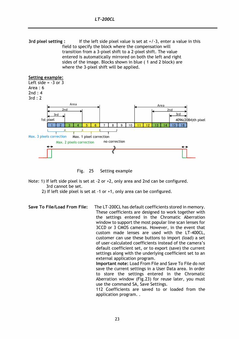
3rd pixel setting : If the left side pixel value is set at +/-3, enter a value in this
field to specify the block where the compensation will transition from a 3-pixel shift to a 2-pixel shift. The value entered is automatically mirrored on both the left and right sides of the image. Blocks shown in blue ( 1 and 2 block) are where the 3-pixel shift will be applied.
Setting example: Left side = -3 or 3 Area : 6 2nd : 4 3rd : 2
Fig. 25 Setting example Note: 1) If left side pixel is set at -2 or +2, only area and 2nd can be configured. 3rd cannot be set. 2) If left side pixel is set at -1 or +1, only area can be configured. Save To File/Load From File: The LT-200CL has default coefficients stored in memory.
These coefficients are designed to work together with the settings entered in the Chromatic Aberration window to support the most popular line scan lenses for 3CCD or 3 CMOS cameras. However, in the event that custom made lenses are used with the LT-400CL, customer can use these buttons to import (load) a set of user-calculated coefficients instead of the camera’s default coefficient set, or to export (save) the current settings along with the underlying coefficient set to an external application program. Important note: Load From File and Save To File do not save the current settings in a User Data area. In order to store the settings entered in the Chromatic Aberration window (Fig.23) for reuse later, you must use the command SA, Save Settings. 112 Coefficients are saved to or loaded from the application program. .
13 14 15 167 8 9 10 11 1261 2 3 4 5
Area
2nd
3rd
Area
2nd3rd
1st pixel 4096(2084)th pixel
Max. 3 pixels correction
Max. 2 pixels correction
Max. 1 pixel correction
no correction
LT-200CL
24
Caution on calibration: The object must be charts or materials which have clear and sharp discrimination of white and black edges. The volume of color difference in peripheral area is measured by using the image analysis software. Check how many pixels of R and B channels are shifted against G channel. In this function, maximum three pixels are compensated. For instance, if R channel is shifted 1 pixel to the left in the left end of the image, this means “-1” and set the command CABLR to 1. The compensation for the right side is automatically effected. 6.3.12 Aperture filter
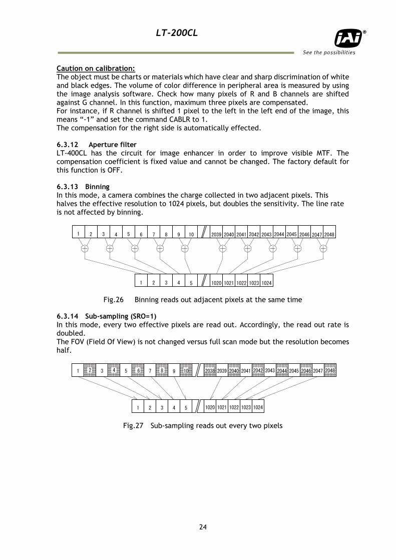
LT-400CL has the circuit for image enhancer in order to improve visible MTF. The compensation coefficient is fixed value and cannot be changed. The factory default for this function is OFF. 6.3.13 Binning
In this mode, a camera combines the charge collected in two adjacent pixels. This halves the effective resolution to 1024 pixels, but doubles the sensitivity. The line rate is not affected by binning.
Fig.26 Binning reads out adjacent pixels at the same time 6.3.14 Sub-sampling (SRO=1)
In this mode, every two effective pixels are read out. Accordingly, the read out rate is doubled. The FOV (Field Of View) is not changed versus full scan mode but the resolution becomes half.
Fig.27 Sub-sampling reads out every two pixels
1 2 3 4 5 6 7 8 9 10
54321
2048204720462045204420432042204120402039
10241023102210211020
1 3 5 7 9
54321
2 4 6 8 10 20482047204620452044204320422041204020392038
10241023102210211020
LT-200CL
25
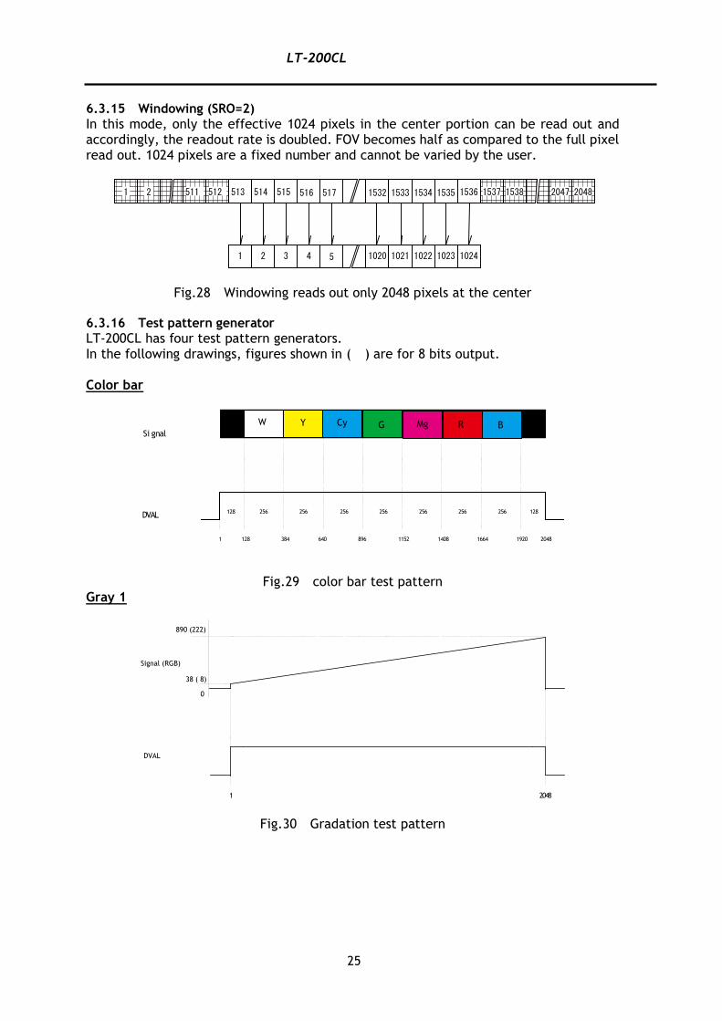
6.3.15 Windowing (SRO=2)
In this mode, only the effective 1024 pixels in the center portion can be read out and accordingly, the readout rate is doubled. FOV becomes half as compared to the full pixel read out. 1024 pixels are a fixed number and cannot be varied by the user.
Fig.28 Windowing reads out only 2048 pixels at the center 6.3.16 Test pattern generator
LT-200CL has four test pattern generators. In the following drawings, figures shown in ( ) are for 8 bits output. Color bar
Fig.29 color bar test pattern
Gray 1
Fig.30 Gradation test pattern
54321
1 2 511 512 513 514 515 516 517 2048204715361535153415331532 1537 1538
10241023102210211020
マゼンタ 赤緑シアン黄白Si gnal
DVAL
1
128 256 256 256 256 256 256 256 128
128 384 640 896 1152 1408 1664 1920 2048
W Y Cy G Mg R B
0
1 2048
890 (222)
38 ( 8)
DVAL
Signal (RGB)
LT-200CL
26
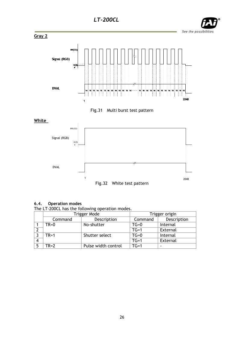
Gray 2
Fig.31 Multi burst test pattern White
Fig.32 White test pattern
6.4. Operation modes
The LT-200CL has the following operation modes.
Trigger Mode Trigger origin
Command Description Command Description
1 TR=0 No-shutter TG=0 Internal
2 TG=1 External
3 TR=1 Shutter select TG=0 Internal
4 TG=1 External
5 TR=2 Pulse width control TG=1 -
32( 8)
0
890( 222)
Signal (RGB)
DVAL
1 2048
LT-200CL
27
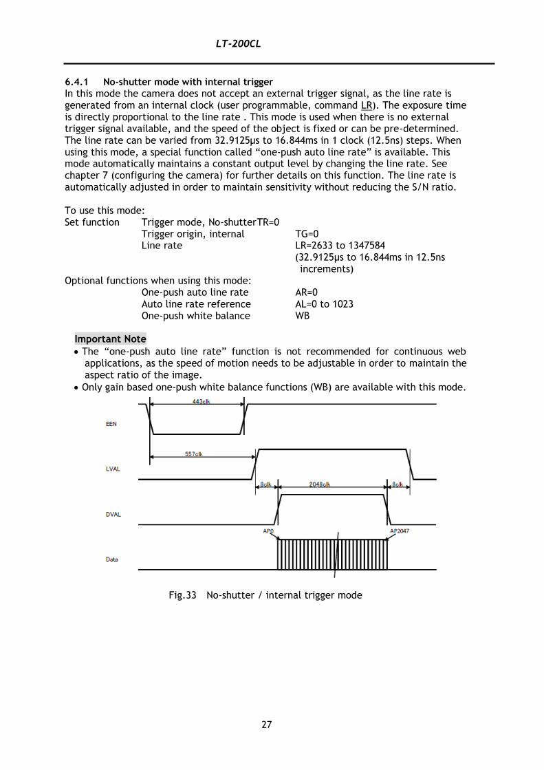
6.4.1 No-shutter mode with internal trigger
In this mode the camera does not accept an external trigger signal, as the line rate is generated from an internal clock (user programmable, command LR). The exposure time is directly proportional to the line rate . This mode is used when there is no external trigger signal available, and the speed of the object is fixed or can be pre-determined. The line rate can be varied from 32.9125μs to 16.844ms in 1 clock (12.5ns) steps. When using this mode, a special function called “one-push auto line rate” is available. This mode automatically maintains a constant output level by changing the line rate. See chapter 7 (configuring the camera) for further details on this function. The line rate is automatically adjusted in order to maintain sensitivity without reducing the S/N ratio. To use this mode: Set function Trigger mode, No-shutter TR=0 Trigger origin, internal TG=0 Line rate LR=2633 to 1347584
(32.9125µs to 16.844ms in 12.5ns increments)
Optional functions when using this mode: One-push auto line rate AR=0 Auto line rate reference AL=0 to 1023 One-push white balance WB
Important Note
The “one-push auto line rate” function is not recommended for continuous web applications, as the speed of motion needs to be adjustable in order to maintain the aspect ratio of the image.
Only gain based one-push white balance functions (WB) are available with this mode.
Fig.33 No-shutter / internal trigger mode
LT-200CL
28
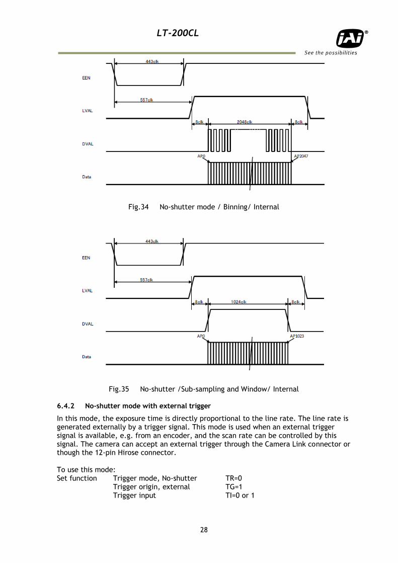
Fig.34 No-shutter mode / Binning/ Internal
Fig.35 No-shutter /Sub-sampling and Window/ Internal 6.4.2 No-shutter mode with external trigger
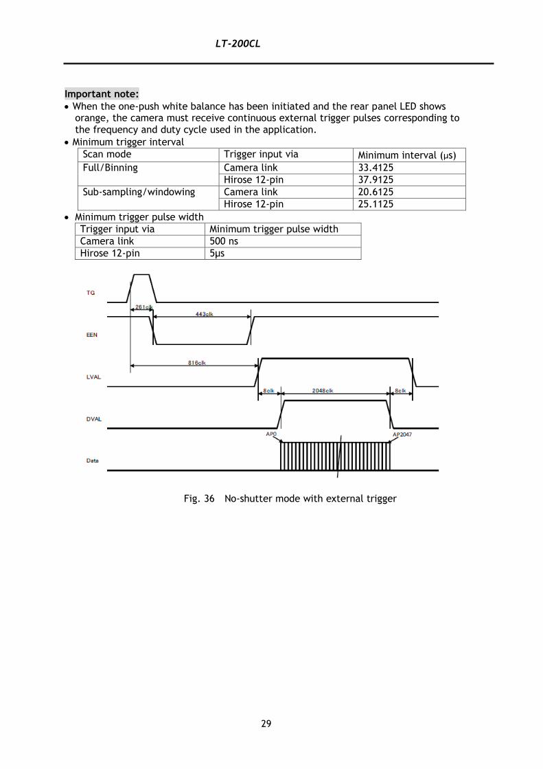
In this mode, the exposure time is directly proportional to the line rate. The line rate is generated externally by a trigger signal. This mode is used when an external trigger signal is available, e.g. from an encoder, and the scan rate can be controlled by this signal. The camera can accept an external trigger through the Camera Link connector or though the 12-pin Hirose connector. To use this mode: Set function Trigger mode, No-shutter TR=0 Trigger origin, external TG=1 Trigger input TI=0 or 1
Clearer timing diagram required. No need to show internal clock
signals.
LT-200CL
29
Important note:
When the one-push white balance has been initiated and the rear panel LED shows orange, the camera must receive continuous external trigger pulses corresponding to the frequency and duty cycle used in the application.
Minimum trigger interval
Scan mode Trigger input via Minimum interval (µs)
Full/Binning Camera link 33.4125
Hirose 12-pin 37.9125
Sub-sampling/windowing Camera link 20.6125
Hirose 12-pin 25.1125
Minimum trigger pulse width
Trigger input via Minimum trigger pulse width
Camera link 500 ns
Hirose 12-pin 5µs
Fig. 36 No-shutter mode with external trigger
LT-200CL
30
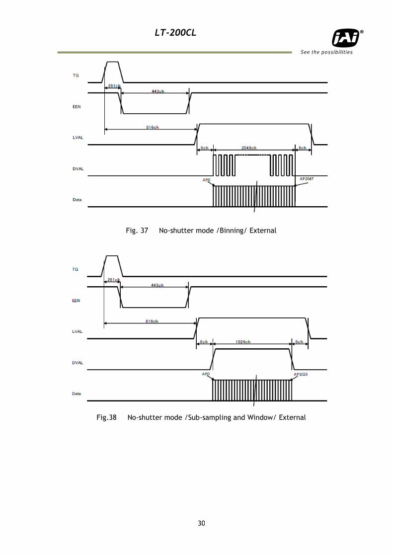
Fig. 37 No-shutter mode /Binning/ External
Fig.38 No-shutter mode /Sub-sampling and Window/ External
LT-200CL
31
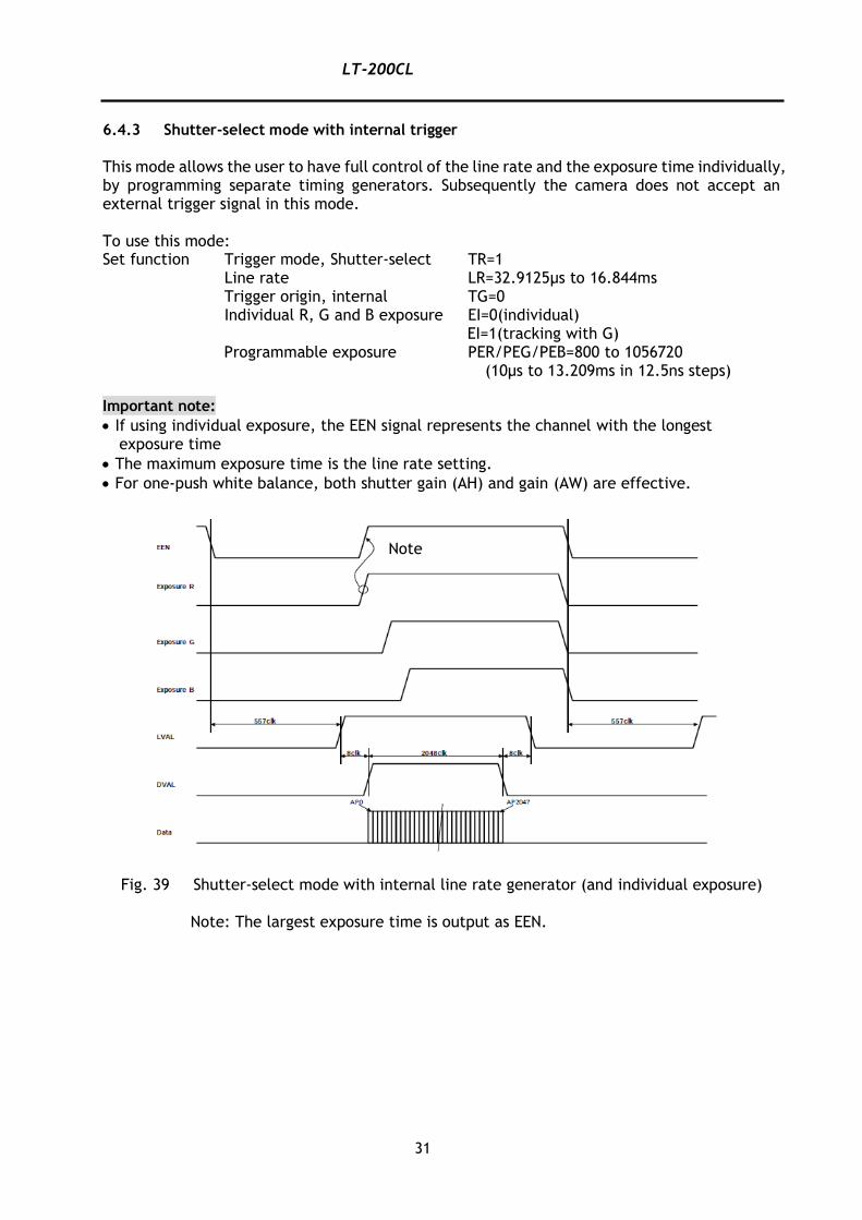
6.4.3 Shutter-select mode with internal trigger
This mode allows the user to have full control of the line rate and the exposure time individually, by programming separate timing generators. Subsequently the camera does not accept an external trigger signal in this mode. To use this mode: Set function Trigger mode, Shutter-select TR=1 Line rate LR=32.9125μs to 16.844ms Trigger origin, internal TG=0 Individual R, G and B exposure EI=0(individual)
EI=1(tracking with G) Programmable exposure PER/PEG/PEB=800 to 1056720
(10µs to 13.209ms in 12.5ns steps) Important note:
If using individual exposure, the EEN signal represents the channel with the longest exposure time
The maximum exposure time is the line rate setting.
For one-push white balance, both shutter gain (AH) and gain (AW) are effective.
Fig. 39 Shutter-select mode with internal line rate generator (and individual exposure)
Note: The largest exposure time is output as EEN.
Note
LT-200CL
32
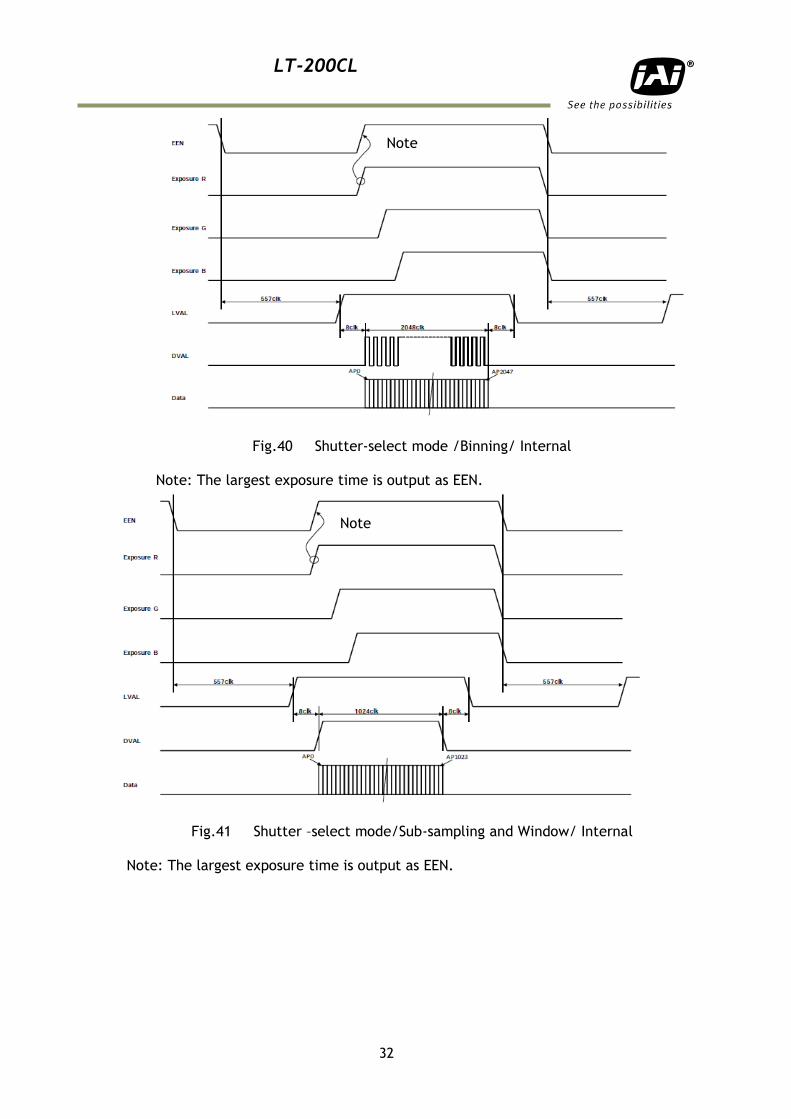
Fig.40 Shutter-select mode /Binning/ Internal
Note: The largest exposure time is output as EEN.
Fig.41 Shutter –select mode/Sub-sampling and Window/ Internal
Note: The largest exposure time is output as EEN.
Note
Note
LT-200CL
33
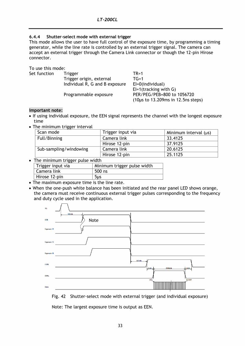
6.4.4 Shutter-select mode with external trigger
This mode allows the user to have full control of the exposure time, by programming a timing generator, while the line rate is controlled by an external trigger signal. The camera can accept an external trigger through the Camera Link connector or though the 12-pin Hirose connector. To use this mode: Set function Trigger TR=1 Trigger origin, external TG=1 Individual R, G and B exposure EI=0(individual)
EI=1(tracking with G) Programmable exposure PER/PEG/PEB=800 to 1056720
(10µs to 13.209ms in 12.5ns steps) Important note:
If using individual exposure, the EEN signal represents the channel with the longest exposure time
The minimum trigger interval
Scan mode Trigger input via Minimum interval (µs)
Full/Binning Camera link 33.4125
Hirose 12-pin 37.9125
Sub-sampling/windowing Camera link 20.6125
Hirose 12-pin 25.1125
The minimum trigger pulse width
Trigger input via Minimum trigger pulse width
Camera link 500 ns
Hirose 12-pin 5µs
The maximum exposure time is the line rate.
When the one-push white balance has been initiated and the rear panel LED shows orange, the camera must receive continuous external trigger pulses corresponding to the frequency and duty cycle used in the application.
Fig. 42 Shutter-select mode with external trigger (and individual exposure)
Note: The largest exposure time is output as EEN.
Clearer timing diagram required. No need to show internal clock signals.
Note
LT-200CL
34
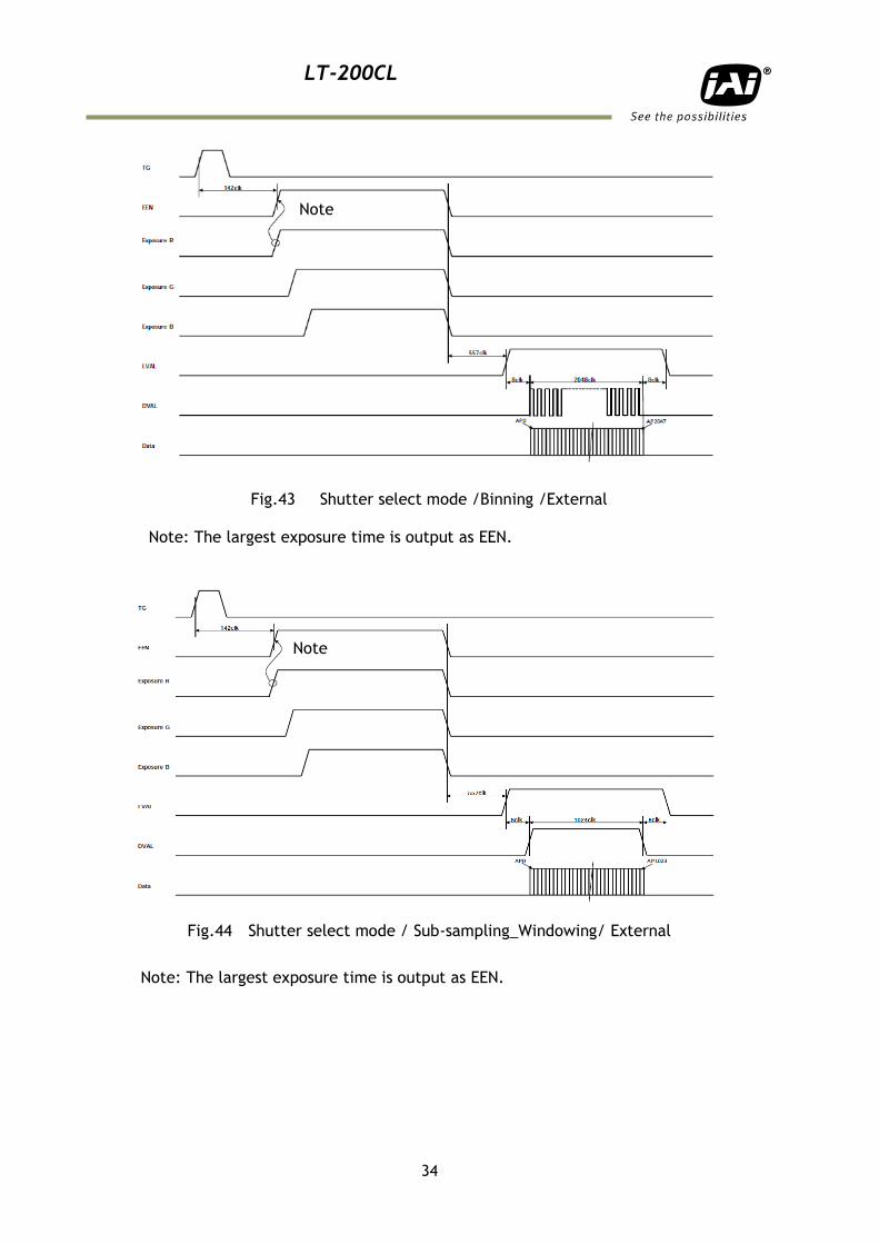
Fig.43 Shutter select mode /Binning /External
Note: The largest exposure time is output as EEN.
Fig.44 Shutter select mode / Sub-sampling_Windowing/ External
Note: The largest exposure time is output as EEN.
Note
Note
LT-200CL
35
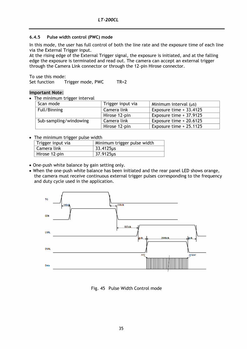
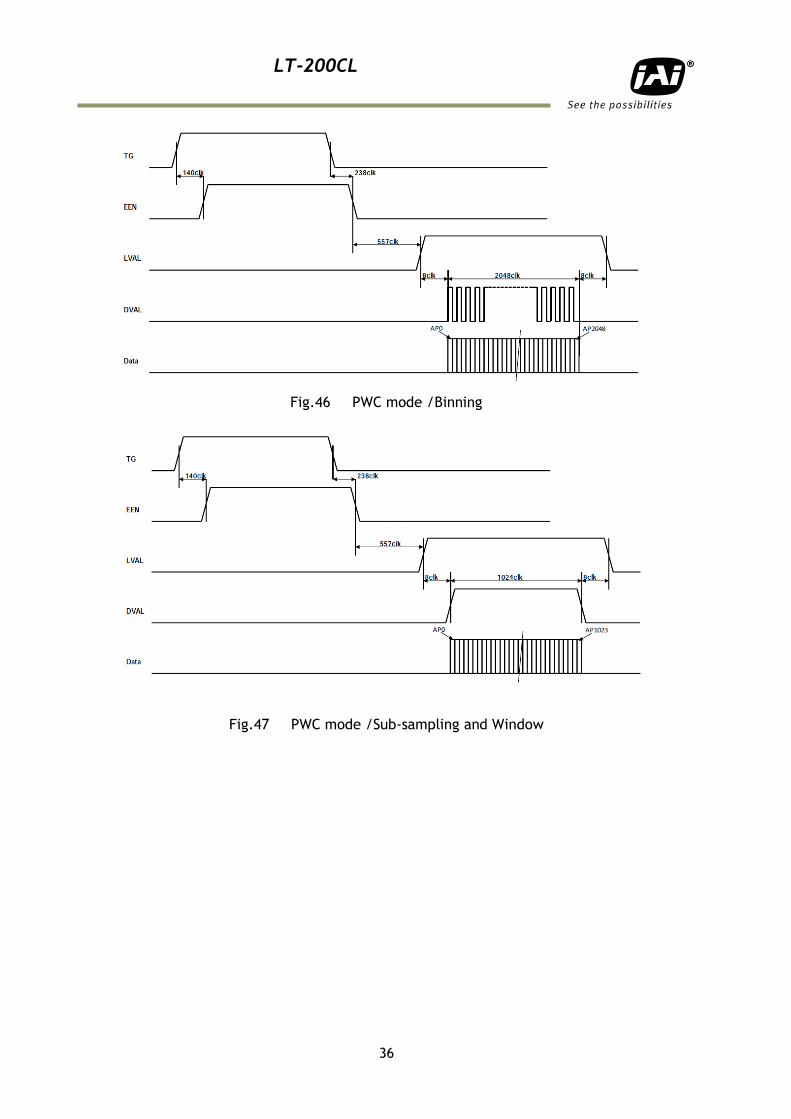
6.4.5 Pulse width control (PWC) mode
In this mode, the user has full control of both the line rate and the exposure time of each line via the External Trigger input. At the rising edge of the External Trigger signal, the exposure is initiated, and at the falling edge the exposure is terminated and read out. The camera can accept an external trigger through the Camera Link connector or through the 12-pin Hirose connector. To use this mode: Set function Trigger mode, PWC TR=2 Important Note:
The minimum trigger interval
Scan mode Trigger input via Minimum interval (µs)
Full/Binning Camera link Exposure time + 33.4125
Hirose 12-pin Exposure time + 37.9125
Sub-sampling/windowing Camera link Exposure time + 20.6125
Hirose 12-pin Exposure time + 25.1125
The minimum trigger pulse width
Trigger input via Minimum trigger pulse width
Camera link 33.4125µs
Hirose 12-pin 37.9125µs
One-push white balance by gain setting only.
When the one-push white balance has been initiated and the rear panel LED shows orange, the camera must receive continuous external trigger pulses corresponding to the frequency and duty cycle used in the application.
Fig. 45 Pulse Width Control mode
LT-200CL
36
Fig.46 PWC mode /Binning
Fig.47 PWC mode /Sub-sampling and Window
LT-200CL
37
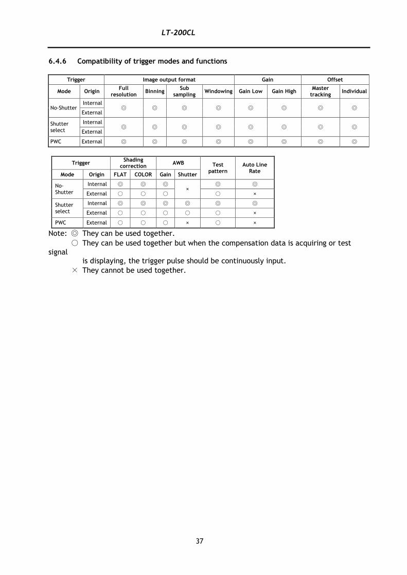
6.4.6 Compatibility of trigger modes and functions
Trigger Image output format Gain Offset
Mode Origin Full
resolution Binning
Sub sampling
Windowing Gain Low Gain High Master
tracking Individual
No-Shutter Internal
◎ ◎ ◎ ◎ ◎ ◎ ◎ ◎ External
Shutter select
Internal ◎ ◎ ◎ ◎ ◎ ◎ ◎ ◎
External
PWC External ◎ ◎ ◎ ◎ ◎ ◎ ◎ ◎
Trigger Shading
correction AWB Test
pattern Auto Line
Rate Mode Origin FLAT COLOR Gain Shutter
No-
Shutter
Internal ◎ ◎ ◎ ×
◎ ◎
External ○ ○ ○ ○ ×
Shutter select
Internal ◎ ◎ ◎ ◎ ◎ ◎
External ○ ○ ○ ○ ○ ×
PWC External ○ ○ ○ × ○ ×
Note: ◎ They can be used together.
○ They can be used together but when the compensation data is acquiring or test
signal is displaying, the trigger pulse should be continuously input.
× They cannot be used together.
LT-200CL
38
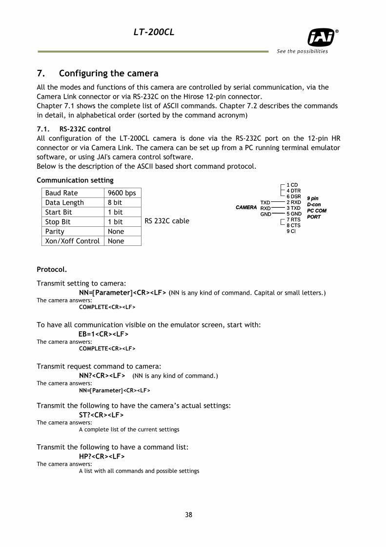
7. Configuring the camera
All the modes and functions of this camera are controlled by serial communication, via the
Camera Link connector or via RS-232C on the Hirose 12-pin connector.
Chapter 7.1 shows the complete list of ASCII commands. Chapter 7.2 describes the commands
in detail, in alphabetical order (sorted by the command acronym)
7.1. RS-232C control
All configuration of the LT-200CL camera is done via the RS-232C port on the 12-pin HR
connector or via Camera Link. The camera can be set up from a PC running terminal emulator
software, or using JAI's camera control software.
Below is the description of the ASCII based short command protocol.
Communication setting
Protocol.
Transmit setting to camera:
NN=Parameter<CR><LF> (NN is any kind of command. Capital or small letters.) The camera answers:
COMPLETE<CR><LF>
To have all communication visible on the emulator screen, start with:
EB=1<CR><LF> The camera answers:
COMPLETE<CR><LF>
Transmit request command to camera:
NN?<CR><LF> (NN is any kind of command.) The camera answers:
NN=Parameter<CR><LF>
Transmit the following to have the camera’s actual settings:
ST?<CR><LF> The camera answers:
A complete list of the current settings
Transmit the following to have a command list:
HP?<CR><LF> The camera answers:
A list with all commands and possible settings
Baud Rate 9600 bps
RS 232C cable
Data Length 8 bit
Start Bit 1 bit
Stop Bit 1 bit
Parity None
Xon/Xoff Control None
TXDRXDGND
1 CD4 DTR6 DSR2 RXD3 TXD5 GND7 RTS8 CTS9 CI
9 pin
D-con
PC COM
PORT
CAMERATXDRXDGND
1 CD4 DTR6 DSR2 RXD3 TXD5 GND7 RTS8 CTS9 CI
9 pin
D-con
PC COM
PORT
CAMERA
LT-200CL
39
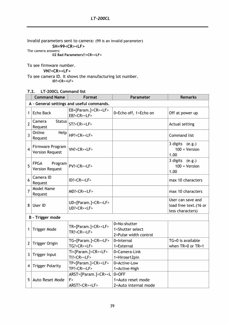
Invalid parameters sent to camera: (99 is an invalid parameter)
SH=99<CR><LF> The camera answers:
02 Bad Parameters!!<CR><LF>
To see firmware number.
VN?<CR><LF>
To see camera ID. It shows the manufacturing lot number. ID?<CR><LF>
7.2. LT-200CL Command list
Command Name Format Parameter Remarks
A – General settings and useful commands.
1 Echo Back EB=[Param.]<CR><LF>
EB?<CR><LF> 0=Echo off, 1=Echo on Off at power up
2 Camera Status
Request ST?<CR><LF> Actual setting
3 Online Help
Request HP?<CR><LF> Command list
4 Firmware Program
Version Request VN?<CR><LF>
3 digits (e.g.)
100 = Version
1.00
5 FPGA Program
Version Request PV?<CR><LF>
3 digits (e.g.)
100 = Version
1.00
6 Camera ID
Request ID?<CR><LF> max 10 characters
7 Model Name
Request MD?<CR><LF> max 10 characters
8 User ID UD=[Param.]<CR><LF>
UD?<CR><LF>
User can save and
load free text.(16 or
less characters)
B - Trigger mode
1 Trigger Mode TR=[Param.]<CR><LF>
TR?<CR><LF>
0=No-shutter
1=Shutter select
2=Pulse width control
2 Trigger Origin TG=[Param.]<CR><LF>
TG?<CR><LF>
0=Internal
1=External
TG=0 is available
when TR=0 or TR=1
3 Trigger Input TI=[Param.]<CR><LF>
TI?<CR><LF>
0=Camera-Link
1=Hirose12pin
4 Trigger Polarity TP=[Param.]<CR><LF>
TP?<CR><LF>
0=Active-Low
1=Active-High
5 Auto Reset Mode
ARST=[Param.]<CR><L
F>
ARST?<CR><LF>
0=OFF
1=Auto reset mode
2=Auto internal mode
LT-200CL
40
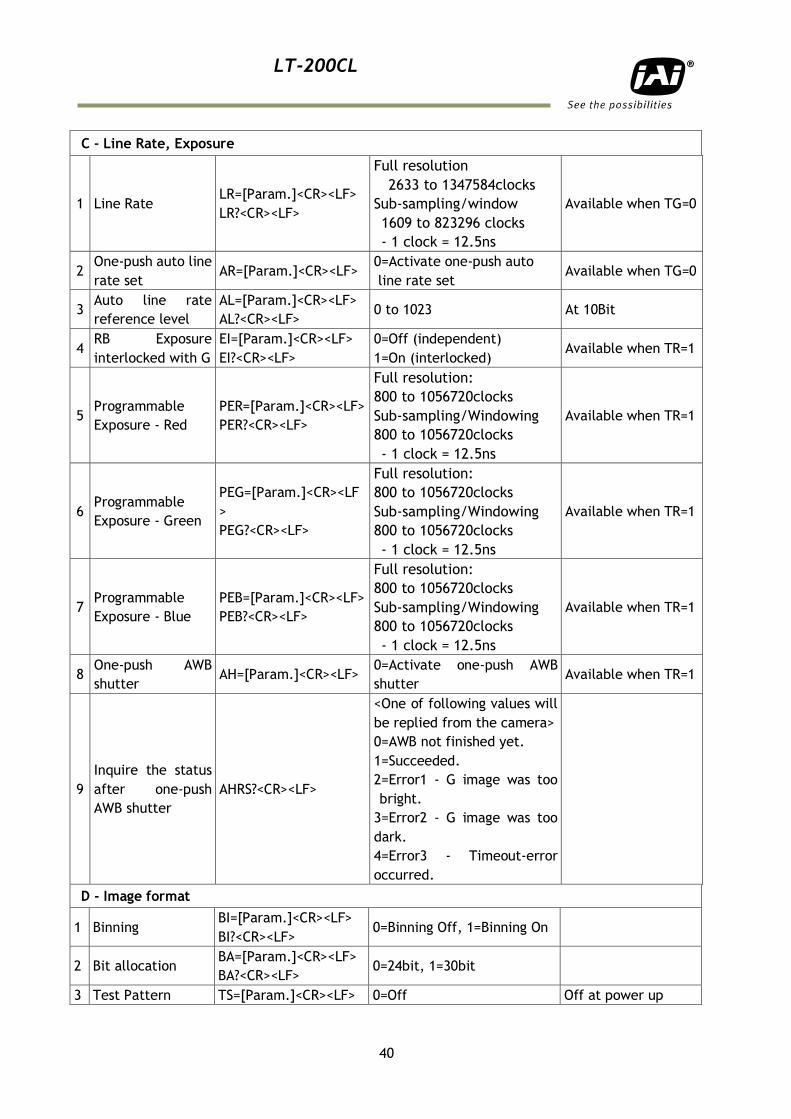
C - Line Rate, Exposure
1 Line Rate LR=[Param.]<CR><LF>
LR?<CR><LF>
Full resolution
2633 to 1347584clocks
Sub-sampling/window
1609 to 823296 clocks
- 1 clock = 12.5ns
Available when TG=0
2 One-push auto line
rate set AR=[Param.]<CR><LF>
0=Activate one-push auto
line rate set Available when TG=0
3 Auto line rate
reference level
AL=[Param.]<CR><LF>
AL?<CR><LF> 0 to 1023 At 10Bit
4 RB Exposure
interlocked with G
EI=[Param.]<CR><LF>
EI?<CR><LF>
0=Off (independent)
1=On (interlocked) Available when TR=1
5 Programmable
Exposure - Red
PER=[Param.]<CR><LF>
PER?<CR><LF>
Full resolution:
800 to 1056720clocks
Sub-sampling/Windowing
800 to 1056720clocks
- 1 clock = 12.5ns
Available when TR=1
6 Programmable
Exposure - Green
PEG=[Param.]<CR><LF
>
PEG?<CR><LF>
Full resolution:
800 to 1056720clocks
Sub-sampling/Windowing
800 to 1056720clocks
- 1 clock = 12.5ns
Available when TR=1
7 Programmable
Exposure - Blue
PEB=[Param.]<CR><LF>
PEB?<CR><LF>
Full resolution:
800 to 1056720clocks
Sub-sampling/Windowing
800 to 1056720clocks
- 1 clock = 12.5ns
Available when TR=1
8 One-push AWB
shutter AH=[Param.]<CR><LF>
0=Activate one-push AWB
shutter Available when TR=1
9
Inquire the status
after one-push
AWB shutter
AHRS?<CR><LF>
<One of following values will
be replied from the camera>
0=AWB not finished yet.
1=Succeeded.
2=Error1 - G image was too
bright.
3=Error2 - G image was too
dark.
4=Error3 - Timeout-error
occurred.
D - Image format
1 Binning BI=[Param.]<CR><LF>
BI?<CR><LF> 0=Binning Off, 1=Binning On
2 Bit allocation BA=[Param.]<CR><LF>
BA?<CR><LF> 0=24bit, 1=30bit
3 Test Pattern TS=[Param.]<CR><LF> 0=Off Off at power up
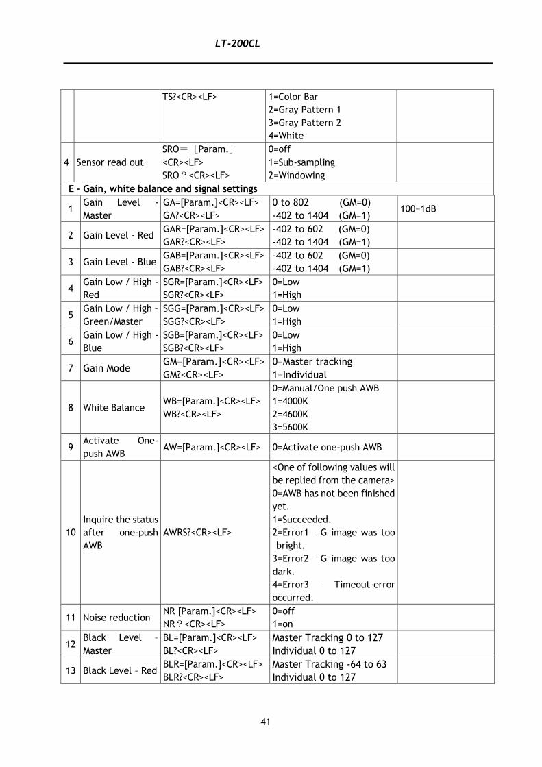
LT-200CL
41
TS?<CR><LF> 1=Color Bar
2=Gray Pattern 1
3=Gray Pattern 2
4=White
4 Sensor read out
SRO=[Param.]
<CR><LF>
SRO?<CR><LF>
0=off
1=Sub-sampling
2=Windowing
E - Gain, white balance and signal settings
1 Gain Level -
Master
GA=[Param.]<CR><LF>
GA?<CR><LF>
0 to 802 (GM=0)
-402 to 1404 (GM=1) 100=1dB
2 Gain Level - Red GAR=[Param.]<CR><LF>
GAR?<CR><LF>
-402 to 602 (GM=0)
-402 to 1404 (GM=1)
3 Gain Level - Blue GAB=[Param.]<CR><LF>
GAB?<CR><LF>
-402 to 602 (GM=0)
-402 to 1404 (GM=1)
4 Gain Low / High -
Red
SGR=[Param.]<CR><LF>
SGR?<CR><LF>
0=Low
1=High
5 Gain Low / High –
Green/Master
SGG=[Param.]<CR><LF>
SGG?<CR><LF>
0=Low
1=High
6 Gain Low / High -
Blue
SGB=[Param.]<CR><LF>
SGB?<CR><LF>
0=Low
1=High
7 Gain Mode GM=[Param.]<CR><LF>
GM?<CR><LF>
0=Master tracking
1=Individual
8 White Balance WB=[Param.]<CR><LF>
WB?<CR><LF>
0=Manual/One push AWB
1=4000K
2=4600K
3=5600K
9 Activate One-
push AWB AW=[Param.]<CR><LF> 0=Activate one-push AWB
10
Inquire the status
after one-push
AWB
AWRS?<CR><LF>
<One of following values will
be replied from the camera>
0=AWB has not been finished
yet.
1=Succeeded.
2=Error1 – G image was too
bright.
3=Error2 – G image was too
dark.
4=Error3 – Timeout-error
occurred.
11 Noise reduction NR [Param.]<CR><LF>
NR?<CR><LF>
0=off
1=on
12 Black Level –
Master
BL=[Param.]<CR><LF>
BL?<CR><LF>
Master Tracking 0 to 127
Individual 0 to 127
13 Black Level – Red BLR=[Param.]<CR><LF>
BLR?<CR><LF>
Master Tracking -64 to 63
Individual 0 to 127
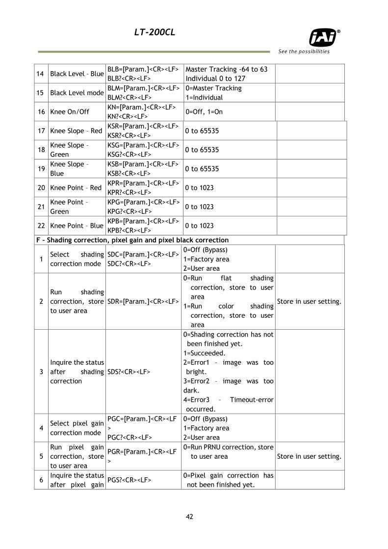
LT-200CL
42
14 Black Level – Blue BLB=[Param.]<CR><LF>
BLB?<CR><LF>
Master Tracking -64 to 63
Individual 0 to 127
15 Black Level mode BLM=[Param.]<CR><LF>
BLM?<CR><LF>
0=Master Tracking
1=Individual
16 Knee On/Off KN=[Param.]<CR><LF>
KN?<CR><LF> 0=Off, 1=On
17 Knee Slope – Red KSR=[Param.]<CR><LF>
KSR?<CR><LF> 0 to 65535
18 Knee Slope –
Green
KSG=[Param.]<CR><LF>
KSG?<CR><LF> 0 to 65535
19 Knee Slope –
Blue
KSB=[Param.]<CR><LF>
KSB?<CR><LF> 0 to 65535
20 Knee Point – Red KPR=[Param.]<CR><LF>
KPR?<CR><LF> 0 to 1023
21 Knee Point –
Green
KPG=[Param.]<CR><LF>
KPG?<CR><LF> 0 to 1023
22 Knee Point – Blue KPB=[Param.]<CR><LF>
KPB?<CR><LF> 0 to 1023
F – Shading correction, pixel gain and pixel black correction
1 Select shading
correction mode
SDC=[Param.]<CR><LF>
SDC?<CR><LF>
0=Off (Bypass)
1=Factory area
2=User area
2
Run shading
correction, store
to user area
SDR=[Param.]<CR><LF>
0=Run flat shading
correction, store to user
area
1=Run color shading
correction, store to user
area
Store in user setting.
3
Inquire the status
after shading
correction
SDS?<CR><LF>
0=Shading correction has not
been finished yet.
1=Succeeded.
2=Error1 – image was too
bright.
3=Error2 – image was too
dark.
4=Error3 – Timeout-error
occurred.
4 Select pixel gain
correction mode
PGC=[Param.]<CR><LF
>
PGC?<CR><LF>
0=Off (Bypass)
1=Factory area
2=User area
5
Run pixel gain
correction, store
to user area
PGR=[Param.]<CR><LF
>
0=Run PRNU correction, store
to user area
Store in user setting.
6 Inquire the status
after pixel gain PGS?<CR><LF>
0=Pixel gain correction has
not been finished yet.
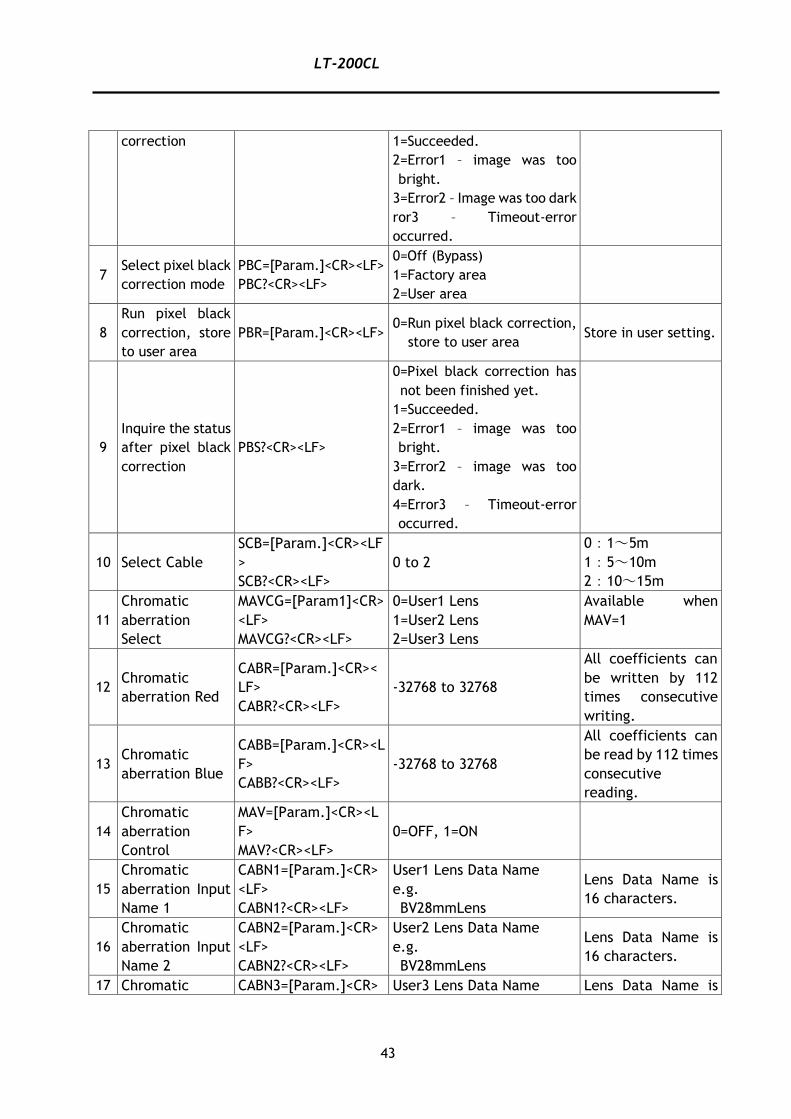
LT-200CL
43
correction 1=Succeeded.
2=Error1 – image was too
bright.
3=Error2 – Image was too dark
ror3 – Timeout-error
occurred.
7 Select pixel black
correction mode
PBC=[Param.]<CR><LF>
PBC?<CR><LF>
0=Off (Bypass)
1=Factory area
2=User area
8
Run pixel black
correction, store
to user area
PBR=[Param.]<CR><LF> 0=Run pixel black correction,
store to user area Store in user setting.
9
Inquire the status
after pixel black
correction
PBS?<CR><LF>
0=Pixel black correction has
not been finished yet.
1=Succeeded.
2=Error1 – image was too
bright.
3=Error2 – image was too
dark.
4=Error3 – Timeout-error
occurred.
10 Select Cable
SCB=[Param.]<CR><LF
>
SCB?<CR><LF>
0 to 2
0:1~5m
1:5~10m
2:10~15m
11
Chromatic
aberration
Select
MAVCG=[Param1]<CR>
<LF>
MAVCG?<CR><LF>
0=User1 Lens
1=User2 Lens
2=User3 Lens
Available when
MAV=1
12 Chromatic
aberration Red
CABR=[Param.]<CR><
LF>
CABR?<CR><LF>
-32768 to 32768
All coefficients can
be written by 112
times consecutive
writing.
13 Chromatic
aberration Blue
CABB=[Param.]<CR><L
F>
CABB?<CR><LF>
-32768 to 32768
All coefficients can
be read by 112 times
consecutive
reading.
14
Chromatic
aberration
Control
MAV=[Param.]<CR><L
F>
MAV?<CR><LF>
0=OFF, 1=ON
15
Chromatic
aberration Input
Name 1
CABN1=[Param.]<CR>
<LF>
CABN1?<CR><LF>
User1 Lens Data Name
e.g.
BV28mmLens
Lens Data Name is
16 characters.
16
Chromatic
aberration Input
Name 2
CABN2=[Param.]<CR>
<LF>
CABN2?<CR><LF>
User2 Lens Data Name
e.g.
BV28mmLens
Lens Data Name is
16 characters.
17 Chromatic CABN3=[Param.]<CR> User3 Lens Data Name Lens Data Name is
LT-200CL
44
aberration Input
Name 3
<LF>
CABN3?<CR><LF>
e.g.
BV28mmLens
16 characters.
18
Chromatic
aberration Left
Side Pixel Red
CABLR=[Param1],[Par
am2]<CR><LF>
CABLR?[Param1]<CR>
<LF>
Param1:User No. 0 to 2
Param2:-3,-2,-1,1,2,3
Param1 : Applied
values set in MAVCG
19
Chromatic
aberration Left
Side Pixel Blue
CABLB=[Param1],[Par
am2]<CR><LF>
CABLB?[Param1]<CR><
LF>
Param1:User No. 0 to 2
Param2:-3,-2,-1,1,2,3
Param1 : Applied
values set in MAVCG
20
Chromatic
aberration Area
No. Red
CABAR=[Param1],[Par
am2]<CR><LF>
CABAR?[Param1]<CR>
<LF>
Param1:User No. 0 to 2
Param2:1 to 8
Param1 : Applied
values set in MAVCG
21
Chromatic
aberration Area
No. Blue
CABAB=[Param1],[Par
am2]<CR><LF>
CABAB?[Param1]<CR>
<LF>
Param1:User No. 0 to 2
Param2:1 to 8
Param1 : Applied
values set in MAVCG
22
Chromatic
aberration 2nd
Pixel Red
CABSR=[Param1],[Par
am2]<CR><LF>
CABSR?[Param1]<CR><
LF>
Param1:User No. 0 to 2
Param2:1 to 7
Param1 : Applied
values set in MAVCG
23
Chromatic
aberration 2nd
Pixel Blue
CABSB=[Param1],[Par
am2]<CR><LF>
CABSB?[Param1]<CR><
LF>
Param1:User No. 0 to 2
Param2:1 to 7
Param1 : Applied
values set in MAVCG
24
Chromatic
aberration 3rd
Pixel Red
CABTR=[Param1],[Par
am2]<CR><LF>
CABTR?[Param1]<CR>
<LF>
Param1:User No. 0 to 2
Param2:1 to 6
Param1 : Applied
values set in MAVCG
25
Chromatic
aberration 3rd
Pixel Blue
CABTB=[Param1],[Par
am2]<CR><LF>
CABTB?[Param1]<CR>
<LF>
Param1:User No. 0 to 2
Param2:1 to 6
Param1 : Applied
values set in MAVCG
26 HPF_CTRL
HPFC=[Param.]<CR><
LF>
HPFC?<CR><LF>
0=off
1=on Aperture Correction
G – Saving and loading data in EEPROM
1
Load Settings
(from Camera
EEPROM)
LD=[Param.]<CR><LF>
0=Factory area
1=User area1
2=User area2 Latest used DATA
AREA will become
default at next
power up. 2
Save Settings
(to Camera
EEPROM)
SA=[Param.]<CR><LF>
1=User area1
2=User area2
Note: the parameter 0 is
not allowed.
LT-200CL
45
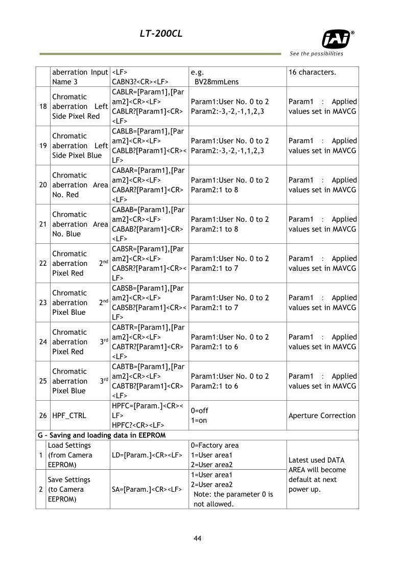
3 EEPROM Current
Area No. Request. EA?<CR><LF>
0=Factory area
1=User area1
2=User area2
The camera returns
latest used DATA
AREA.
Note: To avoid malfunction, do not attempt writing commands not shown in the above list.
8. Functions listed alphabetically by command acronyms
8.1. Command AH – One-push AWB shutter
This command controls a white balance by setting an appropriate shutter speed for
each channel.
Settings: 0 to initiate
Applicable modes: TR=1 Shutter select mode
Associated functions: Commands WB,EI,PER,PEG,PEB
Important Note:
When color temperature of used illumination exceeds the range of adjustment,
proper white balance may not be obtained.
The data can be stored in camera memory for use at next start up.
This function can work on external trigger mode.
The S/N ratio of the output will remain constant for all channels
Refer to chapter 6.3.4 White balance for further details.
8.2. Command AHRS – Request status after One-Push AWB
This command returns the status of the One-Push AWB function, with the following
parameters:
0=AWB not completed yet
1=Succeeded
2=Error1: Green image too bright
3=Error2: Green image too dark
4=Error3: Timeout occurred
8.3. Command AL – Automatic Line Rate Reference Level
Settings: 0 to 1023(10 bit output)
Applicable modes: No-Shutter with Internal trigger
Shutter select with internal trigger
Associated functions: Command AR
8.4. Command AR – Automatic Line Rate setting
This function will calculate and set the line rate of the camera based on the Automatic
Line Rate Reference Level (as set in command AL) and the scene illumination. Please
note that the aspect ratio of the scanned object will change as the line rate is changed.
Settings: 0 (activate automatic process)
Applicable modes: No-Shutter with internal trigger
Shutter select with internal trigger
Associated functions: Command AL, Command TG=0
LT-200CL
46
Important note
The data can be stored in the camera memory for next start up.
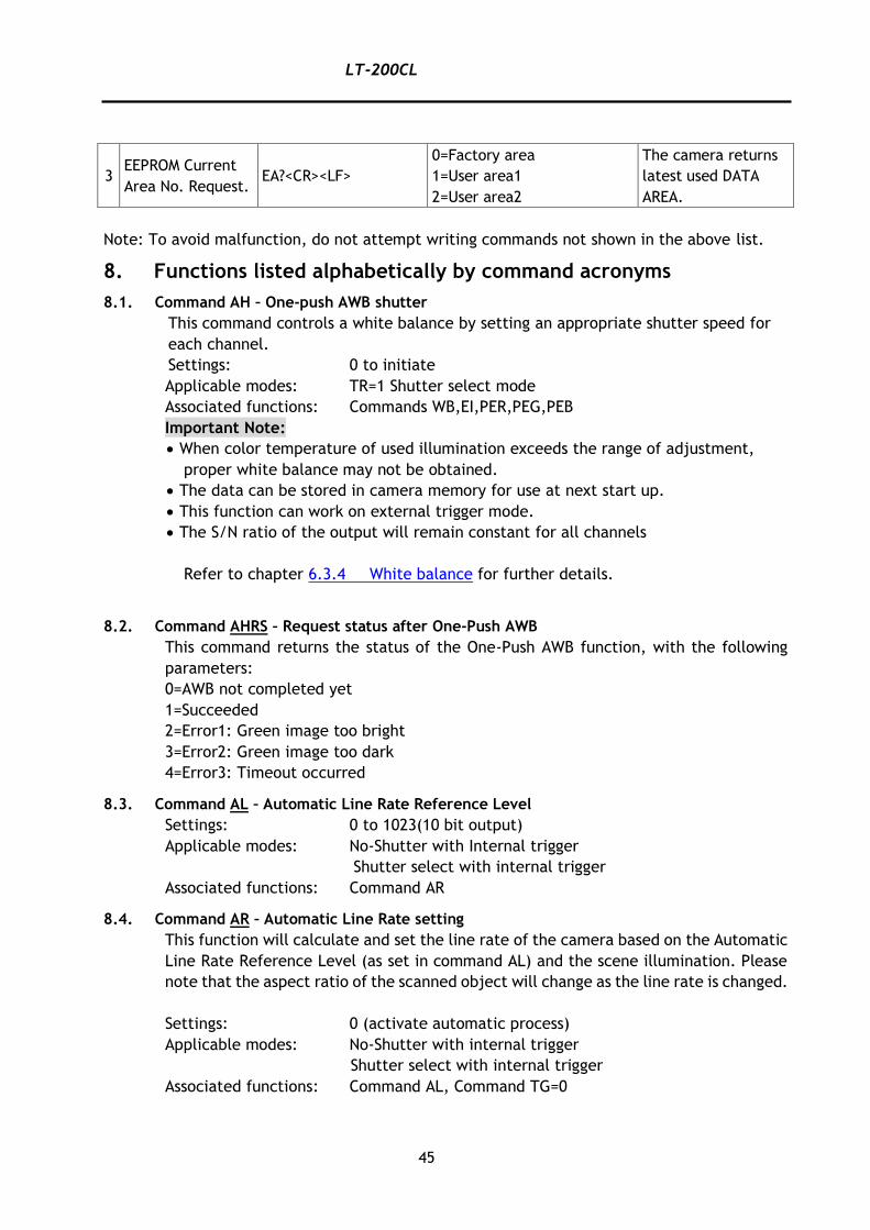
8.5 Command ARST – Auto reset mode
In the no-shutter and external trigger mode, if the trigger is input after a long time
interruption, more than 52msec , the over exposed signal during the trigger
interruption is output after the first trigger. In this case, if ARST mode is ON, LAVL,
DVAL and video signal are not output during the trigger interruption and LAVL, DVAL
and video signal are output after the second trigger input. In the shutter select mode,
the video signal is output with setting exposure time after the first trigger regardless
of
ASRT mode is On or OFF.
Command ARST has two modes. This function is OFF as the default setting.
ARST: 0=OFF
1=Auto Reset
2=Auto Interval
8.5.1 Auto Reset
In No-shutter/External trigger mode, if the trigger is input after long interruption (more
than 52msec), the image exposed during the interruption is output by the first trigger
input. If Auto Reset is enabled, LVAL, DVAL and the image are not output during the
interruption and these signals are output by the second trigger.
In Shutter Select mode, the exposure can be done during the preset time after the
first trigger is input and its image is output regardless of the setting of Auto Reset.
This function can be ON or OFF through communication and the factory default setting
is OFF.
Auto Reset OFF
TG
EEN ① ② ③
LVAL ① ② ③
Auto Reset ON
TG
EEN ① ② ③
t > 52ms
t > 52ms
LT-200CL
47
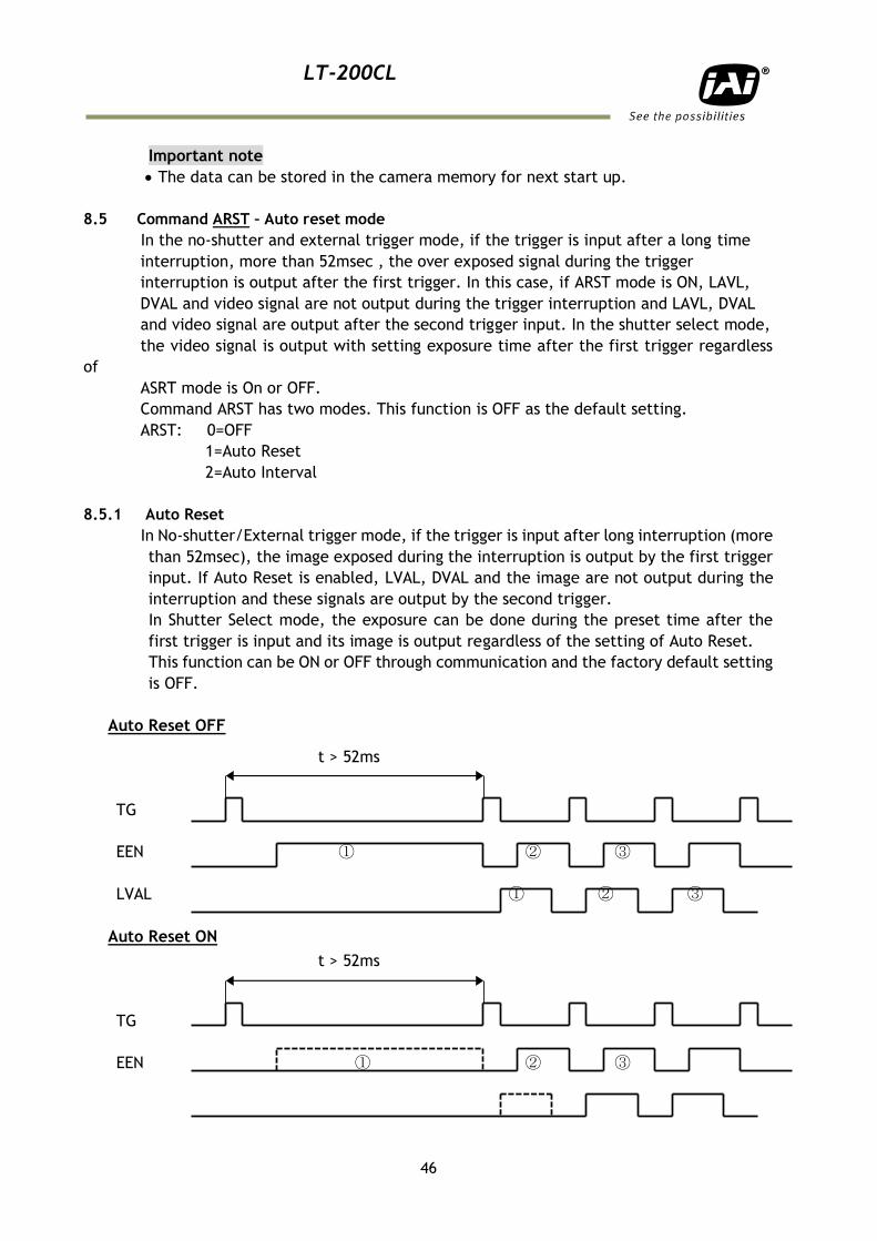
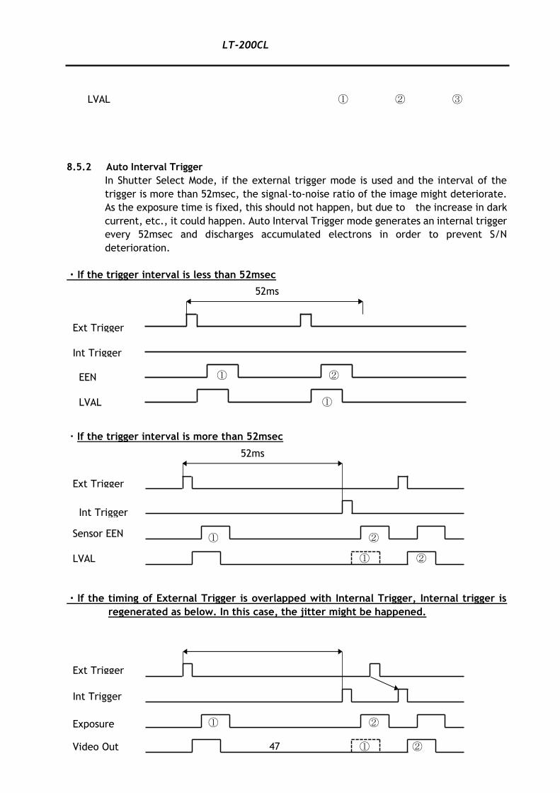
LVAL ① ② ③
8.5.2 Auto Interval Trigger
In Shutter Select Mode, if the external trigger mode is used and the interval of the
trigger is more than 52msec, the signal-to-noise ratio of the image might deteriorate.
As the exposure time is fixed, this should not happen, but due to the increase in dark
current, etc., it could happen. Auto Interval Trigger mode generates an internal trigger
every 52msec and discharges accumulated electrons in order to prevent S/N
deterioration.
・If the trigger interval is less than 52msec
・If the trigger interval is more than 52msec
・If the timing of External Trigger is overlapped with Internal Trigger, Internal trigger is
regenerated as below. In this case, the jitter might be happened.
52ms
Ext Trigger
EEN
Int Trigger
LVAL
① ②
①
52ms
Ext Trigger
Int Trigger
Sensor EEN
LVAL
① ②
① ②
Ext Trigger
Int Trigger
Exposure
Video Out
① ②
① ②
LT-200CL
48
8.6 Command AW – Activate One-push Auto White Balance (AWB) - Gain
By sending this command via the serial communication, the gain based One-Push
AWB function is activated. This function can also be initiated by pressing the rear
panel button. During this time the rear panel LED will show orange.
This function operates in two steps. First the Red-to-Green channel difference and
the Blue-to-Green channel difference is calculated separately. Then the gain of the
Blue and Red channel is automatically adjusted, to obtain the same output level on
all three channels.
Settings: 0 = activate automatic process
Applicable modes: All
Associated functions: Command WB (WB=0), Rear panel One-push WB button.
Important Note:
When color temperature of used illumination exceeds the range of adjustment,
proper white balance may not be obtained.
The data can be stored in camera memory for use at next start up.
This function can work on external trigger mode.
The S/N ratio of the output will change as a result of this function.
Refer to chapter 6.3.4 White balance for further details.
8.7 Command AWRS – Inquire the status after one-push AWB
This command returns the status of the one-push AWB function, with the following
parameters:
0=Shading correction not completed yet
1=Successful
2=Error 1 – Image was too bright
3=Error 2 – Image was too dark
4=Error 3 - Timeout occurred
8.8 Command BA – Bit Allocation
This function lets the user select whether the video data is presented as 3 x 8 (24)-
bit or 3 x 10 (30)-bit on the Camera Link output. The internal processing in the
camera is based on a 12 bit A/D signal. The 24-bit and 30-bit function removes the
least significant bits from the 12 bit signal.
Settings: 0=24-bit, 1=30-bit
Applicable modes: All
8.9 Command BI – Binning (Horizontal only)
This function reduces the number of pixels to 256 without affecting the line rate.
Two adjacent pixels are combined at the output stage and read out as one pixel.
Sensitivity is doubled as a result of binning. Refer to Chapter 6.3.11 Binning for how
LT-200CL
49
it works.
Settings: 1=binning on, 0=binning off
Applicable modes: All
Important Note:
Setting data is stored in camera memory for use at next start up
This function is available for all modes.
8.10 Command BL – Master Black Level
This command is a global black level adjustment for all channels. The adjustable range
for master black is 0LSB to 127 LSB.
Settings: Master tracking 0 to 127
Individual 0 to 127
Associated functions: Command BLR - black level for the red channel.
Command BLB – black level for the blue channel.
8.11 Commands BLR and BLB – Black level red and black level blue
In conjunction with Command BL, these commands allow individual setting of the black
level in all channels.
Settings: Master tracking -64 to 63
Individual 0 to 127
Associated functions: Command BL
Refer to chapter 6.3.6 for further details.
8.12 Command BLM – Black level mode
Select the master tracking mode or the individual mode.
Settings: 0=Master tracking, 1= Individual
8.13 Command CAB – Command for lateral chromatic aberration
Associated commands : MAV, MAVCG
8.14 Command EI – Interlocked R and B exposure with G
When this function enabled (interlocked), exposure time for R and B channels is
interlocked with that of G channel. The Red and Blue channels will track the Green
channel proportionally, thus maintaining white balance settings.
When this is OFF, all channels are adjusted independently.
Settings: 0= OFF (independent R, G and B settings)
1= ON(R and B channels interlocked with G channel)
Applicable modes: TR=1 Shutter-select mode only
Associated functions: Commands PER, PEG, PEB – Programmable Exposure
LT-200CL
50
Refer to 6.3.2 Electronic shutter (Exposure)(Command PER,PEG,PEB) for further
details.
8.15 Command GA – Gain level master / G channel
Adjust the master gain or G channel gain in accordance with gain mode (GM).
GM=0 Master tracking Adjust as master gain
Adjusting range is 0 to 802
GM=1 Individual gain Adjust for G channel
Adjusting range is -402 to 1404
8.16 Commands GAR and GAB – Red and blue gain levels
In conjunction with the Command SGR, SGG and SGB, Gain Low or Gain High this
function allows the individual setting of gain for all channels. It is important to note
that increasing the gain will lead to an increased noise level and reduced S/N-Ratio.
Settings: -402 to 602 (where 100 equals 1dB) (GM=0)
-402 to 1404 (where 100 equals 1dB) (GM=1)
Associated function: Commands SGR, SGG, SGB, GM
Applicable modes: All modes
Refer to chapter 6.3.5 Gain control for further details.
8.17 Command GM – Gain mode
This command sets the master tracking mode or the individual mode.
GM=0 Master tracking
GM=1 Individual mode
8.18 Command HPFC – Aperture filter
This command enables or disables the filter which improves MTF.
HPFC :0=OFF
1=ON
8.19 Command KN – Knee ON/Off
This command activates Knee correction function.
Settings: 0=OFF, 1=ON
8.20 Commands KSR, KSG and KSB – Knee slope for R, G and B
See command KN for description of this function
Settings: 0 to 65535
Associated functions Command KN, Commands KPR, KPG and KPG
8.21 Commands KPR, KPG and KPG – Knee point for R, G and B
See command KN for description of this function
Settings: 0 to 1023
LT-200CL
51
Associated functions: Command KN, Commands KSR, KSG and KSB
Refer to chapter 6.3.7 Knee correction for further details.
8.22 Command LR - Line Rate (Scan Rate)
This function is used only when there is no external trigger pulse (e.g. from an encoder)
available. It allows the user to program the line rate, in order to match the speed of
the object being scanned. In the No-Shutter mode, the exposure time is directly
proportional to the line rate (Texp = 1/line rate)
Settings: 2633 to 1347584,
32.9125μs to 16.844ms in 12.5ns increments
Associated functions: Trigger origin, TG=0
Applicable modes: No-Shutter with internal line rate generator (TR=0)
Shutter-Select with internal line rate generator (TR=1)
Important note
The data can be stored in the camera memory for next start up.
Refer to chapter 6.3.1 Line rate (Command LR) for further details
8.23 Command MAV and MAVCG – Commands for Lateral Chromatic Aberration
Command MAV enables or disables the lateral chromatic aberration function.
MAV: 0=OFF
1=ON
MAVCG can store the data for three types of lens.
0 = User 1 Lens
1 = User 2 Lens
2 = User 3 Lens
Commands, CABN1, CABN2 and CABN3 can give a name to eachlens such as 28mm.
8.24 Command NR – Noise reduction
This command activates noise reduction circuit.
Settings: 0=OFF, 1=ON
8.25 Command PBC – Select pixel black correction mode
This command enables (or disables) the “pixel black level” correction function, which
compensates for Dark Signal Non Uniformity (DSNU / FPN) for individual pixels.
Settings: 0 = Off (Bypass) (Default)
1 = Factory setting
2 = user area
Associated functions: Command PBR
LT-200CL
52
Applicable modes: All
8.26 Command PBR – Run pixel black correction and store to user area
This command initiates the “pixel black level” correction function, and stores the
settings in the user area. When this function is activated, lens must be capped.
Settings: 0 = Run this function
Associated functions: Command PBC must be set to 2
Important note:
This function requires that no light reaches the image sensors. The lens must
therefore be covered by a lens cap, or put the F-mount protective cover on the
camera, when executing this function.
As the black level is influenced by the exposure time (especially for long exposure
time, at slow scan rates) it is recommended to perform the pixel black correction
at the exposure time and line rate at which the camera will be operated.
8.27 Command PBS – Inquire the status of after pixel black correction
This command returns the status of the pixel black correction, with the following
parameters:
0=Shading correction not completed yet
1=Successful
2=Error 1 – Image was too bright
3=Error 2 – Image was too dark
4=Error 3 - Timeout occurred
8.28 Command PER – Programmable exposure – Red
This command allows individual setting of the exposure time of the Red channel. It is
only valid for the Shutter select mode.
Settings: 800 to 1056720 clocks,
10 μs to 13.209ms in 12.5ns steps
Applicable mode: TR=1 Shutter select mode
Associated functions: EI (R and G exposure interlocked with G)
8.29 Command PEG – Programmable exposure – Green
This command allows individual setting of the exposure time of the Green channel. It
is only valid for the Shutter select mode.
Settings: 800 to 1056720 clocks,
10μs to 13.209ms in 12.5ns steps
Applicable mode: TR=1 Shutter select mode
Associated functions: EI (R and G exposure interlocked with G)
LT-200CL
53
8.30 Command PEB – Programmable exposure – Blue
This command allows individual setting of the exposure time of the Blue channel. It is
only valid for the Shutter select mode.
Settings: 800 to 1056720 clocks,
10 μs to 13.209ms in 12.5ns steps
Applicable mode: TR=1 Shutter select mode
Associated functions: EI (R and G exposure interlocked with G)
Refer to chapter 6.3.2 Electronic shutter (Exposure) for further details.
8.31 Command PGC – Pixel gain correction mode
This command enables (or disables) the “pixel gain” (flat-field) correction function,
which compensates for Pixel Response Non Uniformity (PRNU) for individual pixels.
Settings: 0=Off (Bypass) (Default)
1=Factory Setting
2=User area
Associated functions: Command PGR
Applicable modes: All
8.32 Command PGR – Run pixel gain correction and store in user area
This command initiates the flat-field correction function, and stores the settings in the
user area.
Settings: 0= Run PRNU correction and store to user area
Associated functions: Command PGC must be set to 2
Important note:
The image sensors must not be saturated when executing this function.
When executing this function, the exposure time and line rate should be the same
as when the camera is operated in the application.
Refer to chapter 6.3.8 PRNU (Pixel Response Non-Uniformity) correction for further
details.
8.33 Command PGS – Inquire the status after pixel gain correction
This command returns the status of the pixel gain correction, with the following
parameters:
0=Shading correction not completed yet
1=Successful
2=Error 1 – Image was too bright
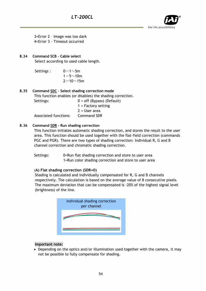
LT-200CL
54
3=Error 2 – Image was too dark
4=Error 3 - Timeout occurred
8.34 Command SCB – Cable select
Select according to used cable length.
Settings : 0=1~5m
1=5~10m
2=10~15m
8.35 Command SDC – Select shading correction mode
This function enables (or disables) the shading correction.
Settings: 0 = off (Bypass) (Default)
1 = Factory setting
2 = User area
Associated functions: Command SDR
8.36 Command SDR – Run shading correction
This function initiates automatic shading correction, and stores the result to the user
area. This function should be used together with the flat-field correction (commands
PGC and PGR). There are two types of shading correction: Individual R, G and B
channel correction and chromatic shading correction.
Settings: 0=Run flat shading correction and store to user area
1=Run color shading correction and store to user area
(A) Flat shading correction (SDR=0)
Shading is calculated and individually compensated for R, G and B channels
respectively. The calculation is based on the average value of 8 consecutive pixels.
The maximum deviation that can be compensated is -20% of the highest signal level
(brightness) of the line.
Important note:
Depending on the optics and/or illumination used together with the camera, it may
not be possible to fully compensate for shading.
Individual shading correction
per channel
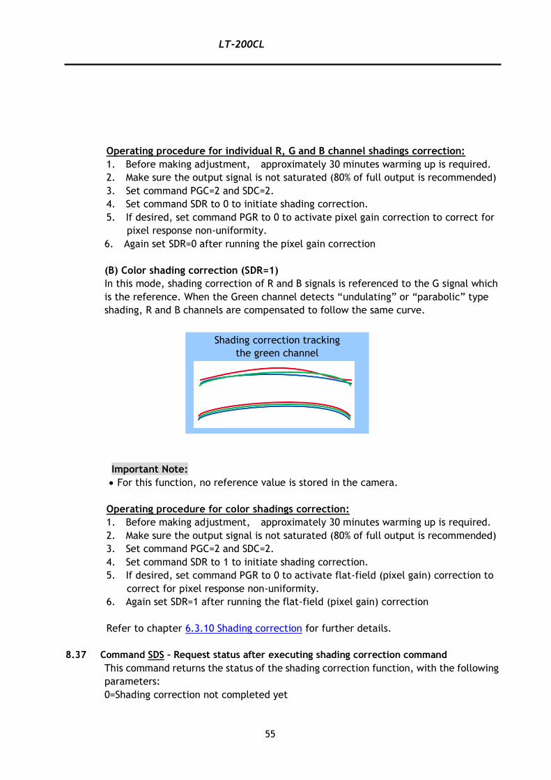
LT-200CL
55
Operating procedure for individual R, G and B channel shadings correction:
1. Before making adjustment, approximately 30 minutes warming up is required.
2. Make sure the output signal is not saturated (80% of full output is recommended)
3. Set command PGC=2 and SDC=2.
4. Set command SDR to 0 to initiate shading correction.
5. If desired, set command PGR to 0 to activate pixel gain correction to correct for
pixel response non-uniformity.
6. Again set SDR=0 after running the pixel gain correction
(B) Color shading correction (SDR=1)
In this mode, shading correction of R and B signals is referenced to the G signal which
is the reference. When the Green channel detects “undulating” or “parabolic” type
shading, R and B channels are compensated to follow the same curve.
Important Note:
For this function, no reference value is stored in the camera.
Operating procedure for color shadings correction:
1. Before making adjustment, approximately 30 minutes warming up is required.
2. Make sure the output signal is not saturated (80% of full output is recommended)
3. Set command PGC=2 and SDC=2.
4. Set command SDR to 1 to initiate shading correction.
5. If desired, set command PGR to 0 to activate flat-field (pixel gain) correction to
correct for pixel response non-uniformity.
6. Again set SDR=1 after running the flat-field (pixel gain) correction
Refer to chapter 6.3.10 Shading correction for further details.
8.37 Command SDS – Request status after executing shading correction command
This command returns the status of the shading correction function, with the following
parameters:
0=Shading correction not completed yet
Shading correction tracking
the green channel
LT-200CL
56
1=Successful
2=Error 1 – Image was too bright
3=Error 2 – Image was too dark
4=Error 3 - Timeout occurred
8.38 Commands SGR,SGG,SGB – Gain Low, High
These commands select the reference level, low or high for red, green and blue.
Settings 0=Low
1=High
Refer to chapter 6.3.5 Gain control for further details.
8.39 Command SRO – Sensor read out
This command selects output format.
Settings: 0=OFF
1=Sub-sampling
2=Windowing
Refer to chapter 6.3.12 Sub-sampling and 6.3.13 Windowing for how they work.
8.40 Command TG – Trigger Origin
Selects whether an external signal or an internal clock generator is used as a trigger
source.
Settings: 0=Internal clock generator
1=External signal
Associated commands: TI,TP
8.41 Command TI – Trigger input
Selects whether the External Trigger input signal is taken from the Camera Link
connector, or from the 12-pin Hirose connector.
Settings: 0=Camera Link connector
1=12-pin Hirose connector
8.42 Command TP – Trigger polarity
Settings: 0=Active Low (factory default)
1=Active High
8.43 Command TR – Trigger Mode
Selects the trigger mode of the camera. Depending on the mode used, it allows the
scan rate to either be programmed by an internal timing generator or by an external
trigger pulse.
Settings: 0=No-Shutter mode
1=Shutter-Select mode
LT-200CL
57
2=Pulse Width Control (PWC) mode
Associated functions: Command TG (trigger origin)
Command TI (trigger input)
Command TP (trigger polarity)
8.44 Command TS – Test pattern
This allows the camera to output a number of test patterns for set-up and
troubleshooting.
Settings: 0=off
1=Color bar
2=Gray wedge
3=Gray bars
4=White (890LSB)
Refer to chapter 6.3.14 Test pattern generator for further details.
8.45 Command WB – White Balance
The white balance function can be used for manual setting, One-Push automatic
white balance (AWB) and fixed color temperatures (3 selections)
Settings: 0=Manual / On-Push AWB
1=4000K
2=4600K
3=5600K
Applicable modes: All
Associated functions: Command AW (Gain)
Refer to chapter 6.3.4 White balance for further details.
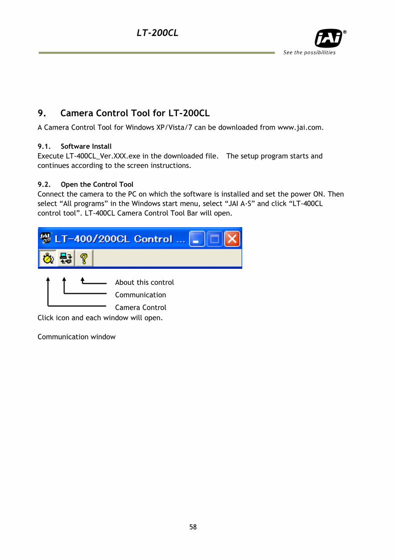
LT-200CL
58
9. Camera Control Tool for LT-200CL
A Camera Control Tool for Windows XP/Vista/7 can be downloaded from www.jai.com.
9.1. Software Install
Execute LT-400CL_Ver.XXX.exe in the downloaded file. The setup program starts and
continues according to the screen instructions.
9.2. Open the Control Tool
Connect the camera to the PC on which the software is installed and set the power ON. Then
select “All programs” in the Windows start menu, select “JAI A-S” and click “LT-400CL
control tool”. LT-400CL Camera Control Tool Bar will open.
Click icon and each window will open.
Communication window
About this control
Communication
Camera Control
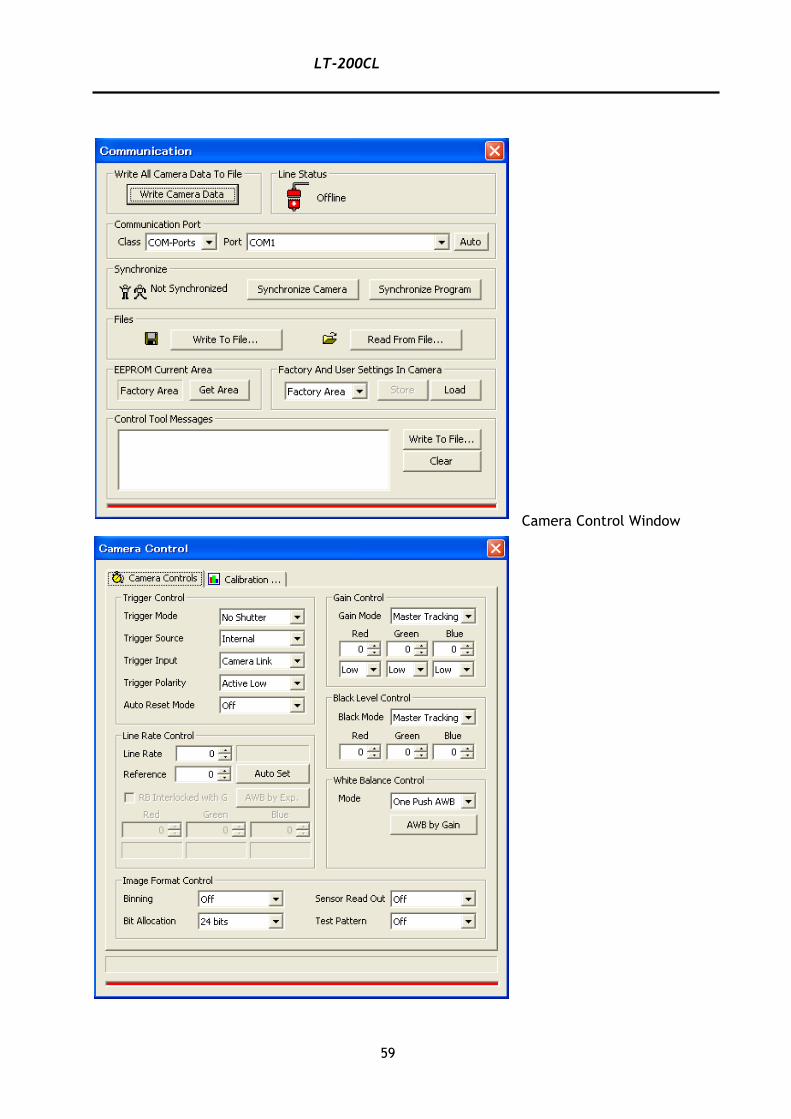
LT-200CL
59
Camera Control Window
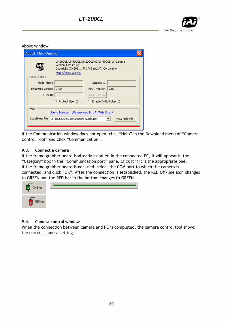
LT-200CL
60
About window
If the Communication window does not open, click “Help” in the Download menu of “Camera
Control Tool” and click “Communication”.
9.3. Connect a camera
If the frame grabber board is already installed in the connected PC, it will appear in the
“Category” box in the “Communication port” pane. Click it if it is the appropriate one.
If the frame grabber board is not used, select the COM port to which the camera is
connected, and click “OK”. After the connection is established, the RED Off-line icon changes
to GREEN and the RED bar in the bottom changes to GREEN.
9.4. Camera control window
When the connection between camera and PC is completed, the camera control tool shows
the current camera settings.
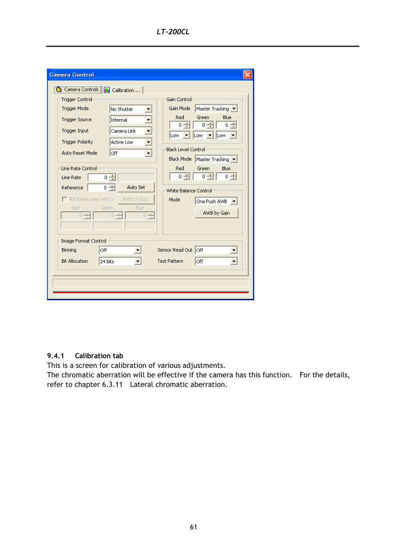
LT-200CL
61
9.4.1 Calibration tab
This is a screen for calibration of various adjustments.
The chromatic aberration will be effective if the camera has this function. For the details,
refer to chapter 6.3.11 Lateral chromatic aberration.
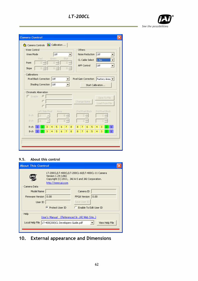
LT-200CL
62
9.5. About this control
10. External appearance and Dimensions
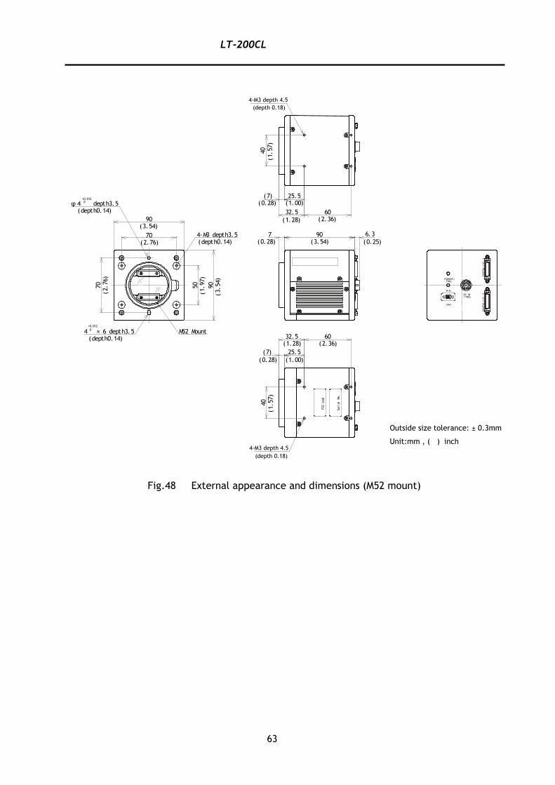
LT-200CL
63
Fig.48 External appearance and dimensions (M52 mount)
907 6.3
(0.28) (3.54) (0.25)
SW1
/TRIGDC IN
W.B.
TRIGPOWER/
DIG
ITA
LI/
O-2
DIG
ITA
LI/
O-1
40
25.5(7)(1.00)(0.28)
32.5 60
(1.28) (2.36)
(1.57)
40
25.5(7)
(0.28) (1.00)
32.5 60(1.28) (2.36)
(1.57)
Serial
No.
FCC
seal
70
50
4-M3 depth3.5
4 × 6 depth3.5+0.0120
70
(depth0.14)
(depth0.14)
90(3.54)
depth3.5φ 4+0.0120
(depth0.14)
(2.76)
(2.76)
(1.97)
90
(3.54)
M52 Mount
Outside size tolerance: ± 0.3mm
Unit:mm , ( ) inch
4-M3 depth 4.5
(depth 0.18)
4-M3 depth 4.5
(depth 0.18)
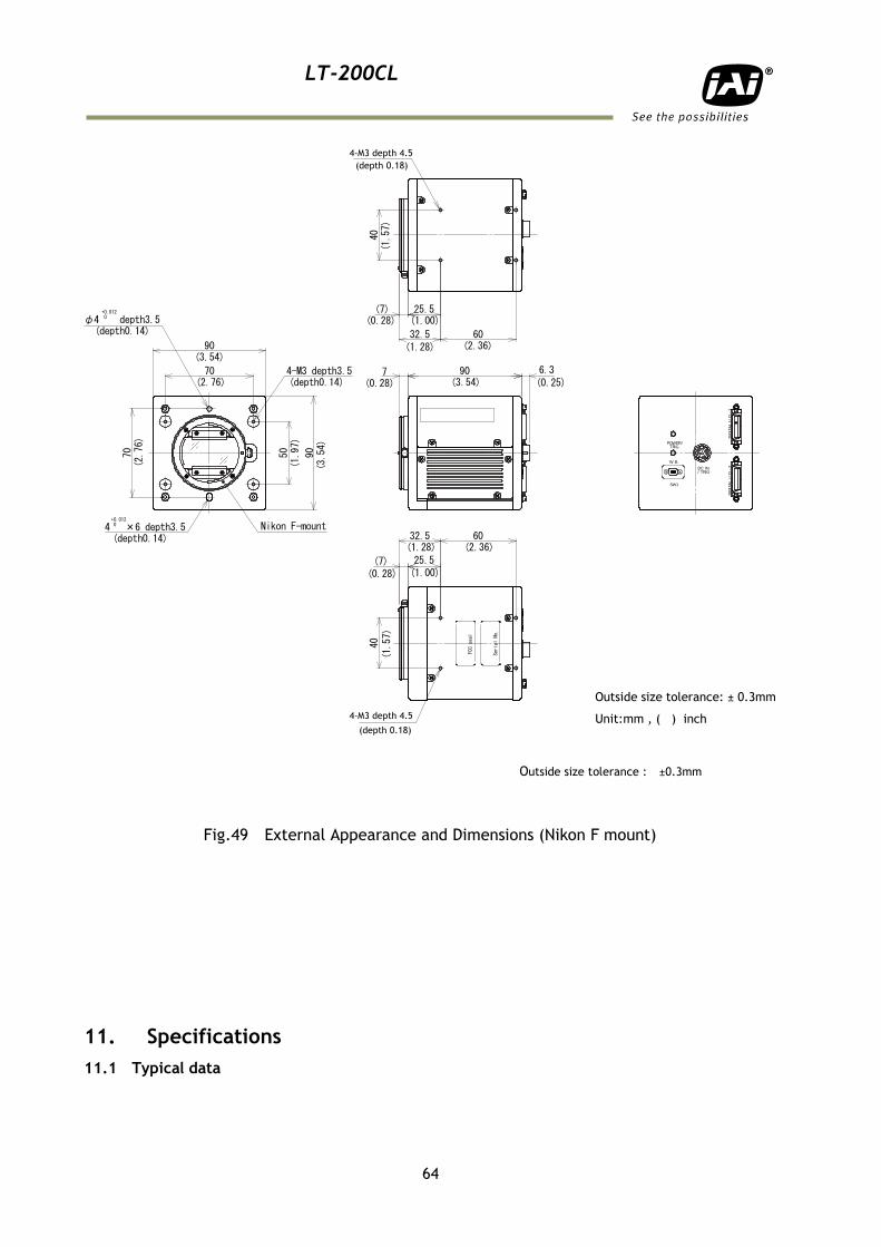
LT-200CL
64
Outside size tolerance : ±0.3mm
Fig.49 External Appearance and Dimensions (Nikon F mount)
11. Specifications
11.1 Typical data
70
50
907 6.34-M3 depth3.5
4 ×6 depth3.5+0.0120
70
(depth0.14)
(depth0.14)
90(3.54)
depth3.5φ4+0.0120
(depth0.14)
(2.76)
(2.76)
(1.97)
90(3.54)
(0.28) (3.54) (0.25)
SW1
/ TRIGDC IN
W.B.
TRIGPOWER/
DIG
ITA
LI/
O-2
DIG
ITA
LI/
O-1
40
25.5(7)(1.00)(0.28)
32.5 60(1.28) (2.36)
(1.57)
40
25.5(7)(0.28) (1.00)
32.5 60(1.28) (2.36)
(1.57)
Serial
No.
FCCseal
Nikon F-mount
Outside size tolerance: ± 0.3mm
Unit:mm , ( ) inch
4-M3 depth 4.5
(depth 0.18)
4-M3 depth 4.5
(depth 0.18)
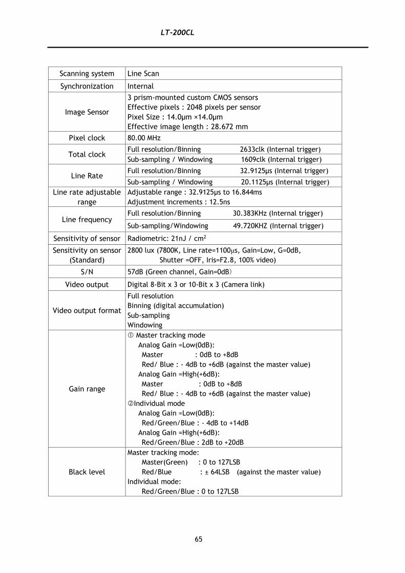
LT-200CL
65
Scanning system Line Scan
Synchronization Internal
Image Sensor
3 prism-mounted custom CMOS sensors
Effective pixels : 2048 pixels per sensor
Pixel Size : 14.0μm ×14.0μm
Effective image length : 28.672 mm
Pixel clock 80.00 MHz
Total clock Full resolution/Binning 2633clk (Internal trigger)
Sub-sampling / Windowing 1609clk (Internal trigger)
Line Rate Full resolution/Binning 32.9125μs (Internal trigger)
Sub-sampling / Windowing 20.1125μs (Internal trigger)
Line rate adjustable
range
Adjustable range : 32.9125μs to 16.844ms
Adjustment increments : 12.5ns
Line frequency Full resolution/Binning 30.383KHz (Internal trigger)
Sub-sampling/Windowing 49.720KHZ (Internal trigger)
Sensitivity of sensor Radiometric: 21nJ / cm2
Sensitivity on sensor
(Standard)
2800 lux (7800K, Line rate=1100μs, Gain=Low, G=0dB,
Shutter =OFF, Iris=F2.8, 100% video)
S/N 57dB (Green channel, Gain=0dB)
Video output Digital 8-Bit x 3 or 10-Bit x 3 (Camera link)
Video output format
Full resolution
Binning (digital accumulation)
Sub-sampling
Windowing
Gain range
Master tracking mode
Analog Gain =Low(0dB):
Master : 0dB to +8dB
Red/ Blue : - 4dB to +6dB (against the master value)
Analog Gain =High(+6dB):
Master : 0dB to +8dB
Red/ Blue : - 4dB to +6dB (against the master value)
Individual mode
Analog Gain =Low(0dB):
Red/Green/Blue : - 4dB to +14dB
Analog Gain =High(+6dB):
Red/Green/Blue : 2dB to +20dB
Black level
Master tracking mode:
Master(Green) : 0 to 127LSB
Red/Blue : ± 64LSB (against the master value)
Individual mode:
Red/Green/Blue : 0 to 127LSB
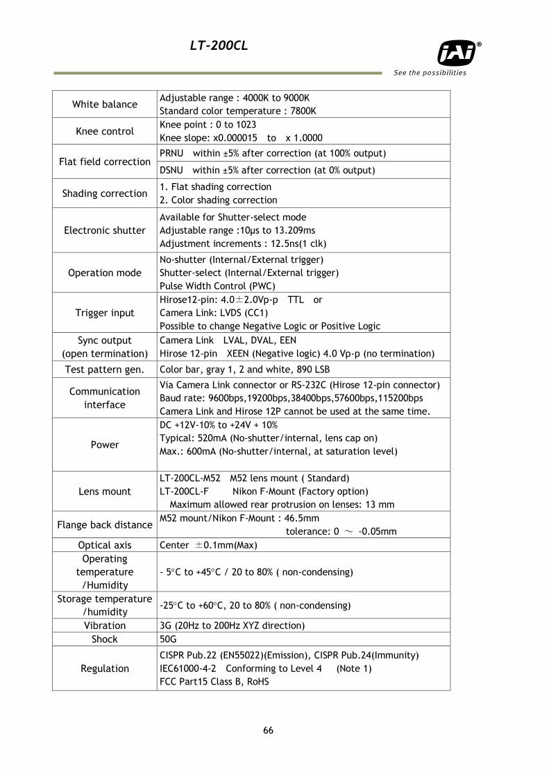
LT-200CL
66
White balance Adjustable range : 4000K to 9000K
Standard color temperature : 7800K
Knee control Knee point : 0 to 1023
Knee slope: x0.000015 to x 1.0000
Flat field correction PRNU within ±5% after correction (at 100% output)
DSNU within ±5% after correction (at 0% output)
Shading correction 1. Flat shading correction
2. Color shading correction
Electronic shutter
Available for Shutter-select mode
Adjustable range :10μs to 13.209ms
Adjustment increments : 12.5ns(1 clk)
Operation mode
No-shutter (Internal/External trigger)
Shutter-select (Internal/External trigger)
Pulse Width Control (PWC)
Trigger input
Hirose12-pin: 4.0±2.0Vp-p TTL or
Camera Link: LVDS (CC1)
Possible to change Negative Logic or Positive Logic
Sync output
(open termination)
Camera Link LVAL, DVAL, EEN
Hirose 12-pin XEEN (Negative logic) 4.0 Vp-p (no termination)
Test pattern gen. Color bar, gray 1, 2 and white, 890 LSB
Communication
interface
Via Camera Link connector or RS-232C (Hirose 12-pin connector)
Baud rate: 9600bps,19200bps,38400bps,57600bps,115200bps
Camera Link and Hirose 12P cannot be used at the same time.
Power
DC +12V-10% to +24V + 10%
Typical: 520mA (No-shutter/internal, lens cap on)
Max.: 600mA (No-shutter/internal, at saturation level)
Lens mount
LT-200CL-M52 M52 lens mount ( Standard)
LT-200CL-F Nikon F-Mount (Factory option)
Maximum allowed rear protrusion on lenses: 13 mm
Flange back distance M52 mount/Nikon F-Mount : 46.5mm
tolerance: 0 ~ -0.05mm
Optical axis Center ±0.1mm(Max)
Operating
temperature
/Humidity
- 5C to +45C / 20 to 80% ( non-condensing)
Storage temperature
/humidity -25C to +60C, 20 to 80% ( non-condensing)
Vibration 3G (20Hz to 200Hz XYZ direction)
Shock 50G
Regulation
CISPR Pub.22 (EN55022)(Emission), CISPR Pub.24(Immunity)
IEC61000-4-2 Conforming to Level 4 (Note 1)
FCC Part15 Class B, RoHS
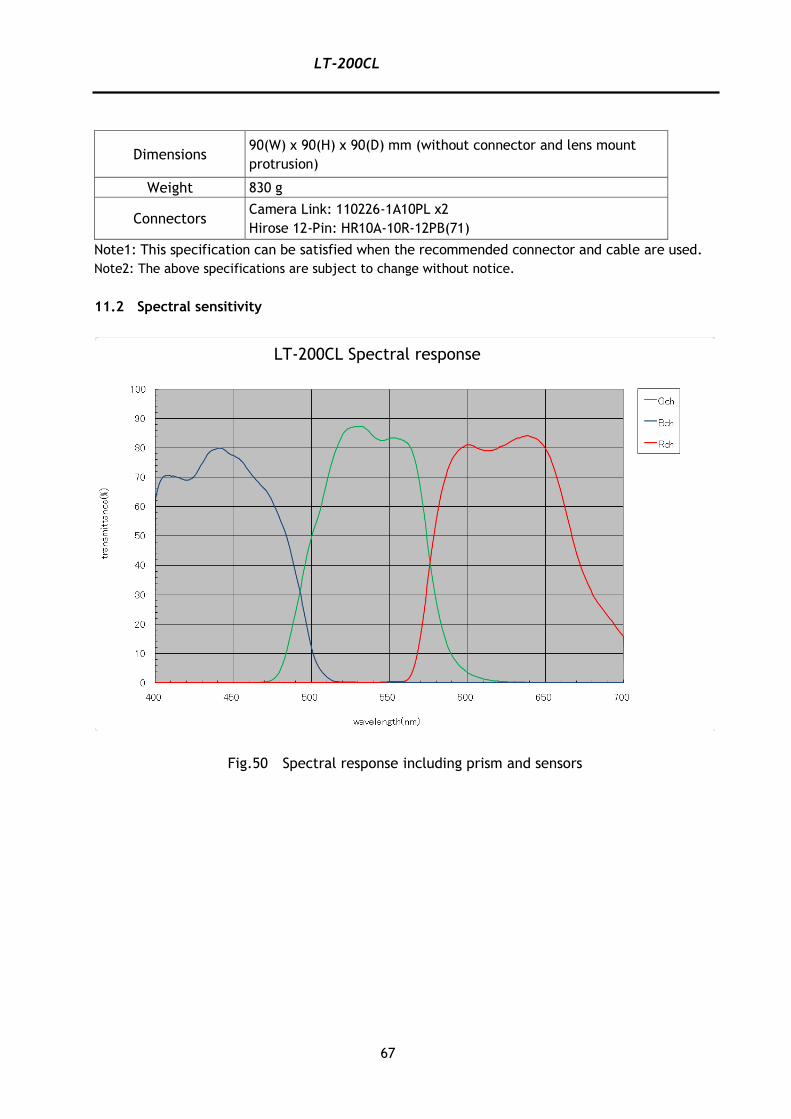
LT-200CL
67
Dimensions 90(W) x 90(H) x 90(D) mm (without connector and lens mount
protrusion)
Weight 830 g
Connectors Camera Link: 110226-1A10PL x2
Hirose 12-Pin: HR10A-10R-12PB(71)
Note1: This specification can be satisfied when the recommended connector and cable are used.
Note2: The above specifications are subject to change without notice.
11.2 Spectral sensitivity
Fig.50 Spectral response including prism and sensors
LT-200CL Spectral response
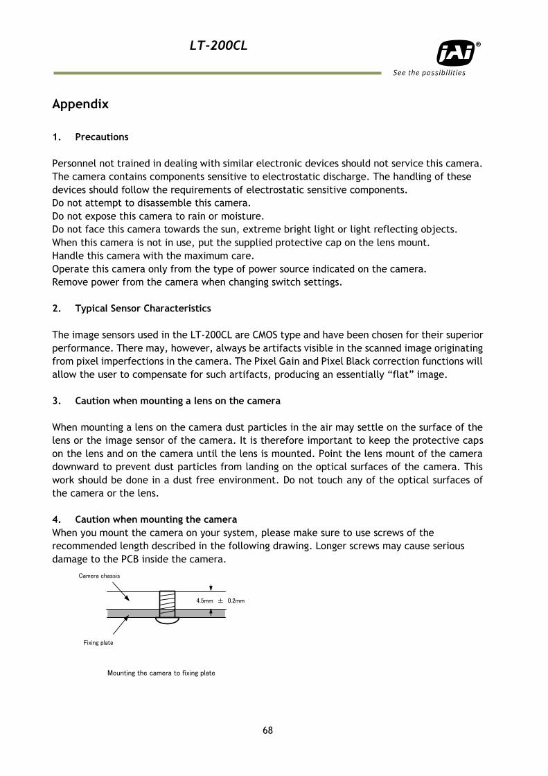
LT-200CL
68
Appendix
1. Precautions
Personnel not trained in dealing with similar electronic devices should not service this camera.
The camera contains components sensitive to electrostatic discharge. The handling of these
devices should follow the requirements of electrostatic sensitive components.
Do not attempt to disassemble this camera.
Do not expose this camera to rain or moisture.
Do not face this camera towards the sun, extreme bright light or light reflecting objects.
When this camera is not in use, put the supplied protective cap on the lens mount.
Handle this camera with the maximum care.
Operate this camera only from the type of power source indicated on the camera.
Remove power from the camera when changing switch settings.
2. Typical Sensor Characteristics
The image sensors used in the LT-200CL are CMOS type and have been chosen for their superior
performance. There may, however, always be artifacts visible in the scanned image originating
from pixel imperfections in the camera. The Pixel Gain and Pixel Black correction functions will
allow the user to compensate for such artifacts, producing an essentially “flat” image.
3. Caution when mounting a lens on the camera
When mounting a lens on the camera dust particles in the air may settle on the surface of the
lens or the image sensor of the camera. It is therefore important to keep the protective caps
on the lens and on the camera until the lens is mounted. Point the lens mount of the camera
downward to prevent dust particles from landing on the optical surfaces of the camera. This
work should be done in a dust free environment. Do not touch any of the optical surfaces of
the camera or the lens.
4. Caution when mounting the camera
When you mount the camera on your system, please make sure to use screws of the
recommended length described in the following drawing. Longer screws may cause serious
damage to the PCB inside the camera.
Camera chassis
Fixing plate
Mounting the camera to fixing plate
4.5mm ± 0.2mm
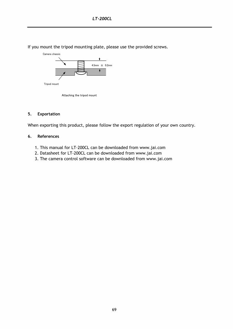
LT-200CL
69
If you mount the tripod mounting plate, please use the provided screws.
5. Exportation
When exporting this product, please follow the export regulation of your own country.
6. References
1. This manual for LT-200CL can be downloaded from www.jai.com
2. Datasheet for LT-200CL can be downloaded from www.jai.com
3. The camera control software can be downloaded from www.jai.com
Camera chassis
Tripod mount
4.5mm ± 0.2mm
Attaching the tripod mount
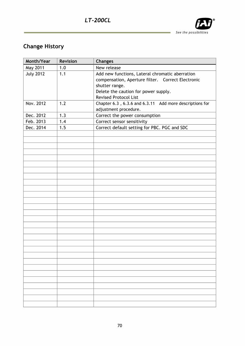
LT-200CL
70
Change History
Month/Year Revision Changes
May 2011 1.0 New release
July 2012 1.1 Add new functions, Lateral chromatic aberration
compensation, Aperture filter. Correct Electronic
shutter range.
Delete the caution for power supply.
Revised Protocol List
Nov. 2012 1.2 Chapter 6.3 , 6.3.6 and 6.3.11 Add more descriptions for
adjustment procedure.
Dec. 2012 1.3 Correct the power consumption
Feb. 2013 1.4 Correct sensor sensitivity
Dec. 2014 1.5 Correct default setting for PBC. PGC and SDC
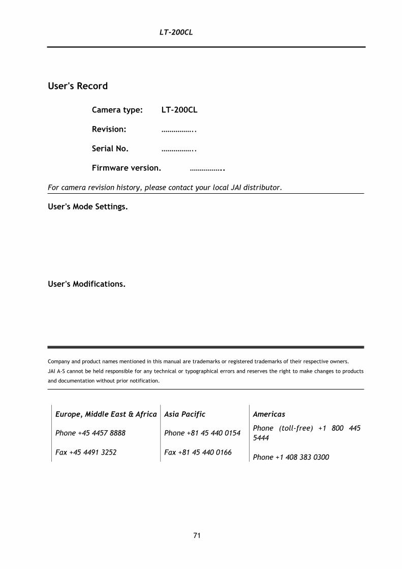
LT-200CL
71
User's Record
Camera type: LT-200CL
Revision: ……………..
Serial No. ……………..
Firmware version. ……………..
For camera revision history, please contact your local JAI distributor.
User's Mode Settings.
User's Modifications.
Company and product names mentioned in this manual are trademarks or registered trademarks of their respective owners.
JAI A-S cannot be held responsible for any technical or typographical errors and reserves the right to make changes to products
and documentation without prior notification.
Europe, Middle East & Africa Asia Pacific Americas
Phone +45 4457 8888
Fax +45 4491 3252
Phone +81 45 440 0154
Fax +81 45 440 0166
Phone (toll-free) +1 800 445
5444
Phone +1 408 383 0300

LT-200CL
72
Visit our web site at www.jai.com