LSA 49.1 - 4 POLES · 2017-09-21 · 2 LEROY-SOMER Installation and maintenance 2014.03 / n LSA...
24
365 2014.03 / n This manual is to be given to the end user 3007 en - LSA 49.1 - 4 POLES ALTERNATORS Installation and maintenance
Transcript of LSA 49.1 - 4 POLES · 2017-09-21 · 2 LEROY-SOMER Installation and maintenance 2014.03 / n LSA...

53
343107
100347
78
37
79349
70
90
1
36
428
41
18
51
31
59
91
278
364
269
368268
279
71
371
177
365
198
172
281
270
21
4
3033
60
284
6815
62
22
34
4849
367
255254
Caixa de terminais opcionais 6 fios com réguas de ligações277
280
281
283172
282
279278
32015
Motor, turbina LSA 49.1 L 11
2014.03 / n
This manual is to be given
to the end user
3007 en -
LSA 49.1 - 4 POLESALTERNATORS
Installation and maintenance

2
LEROY-SOMER 2014.03 / nInstallation and maintenance
LSA 49.1 - 4 POLESALTERNATORS
3007en -
SAFETY MEASURES
Before using your machine for the first time, it is important to read the whole of this installation and maintenance manual.
All necessary operations and interventions on this machine must be performed by a qualified technician.
Our technical support service will be pleased to provide any additional information you may require.
The various operations described in this manual are accompanied by recommenda-tions or symbols to alert the user to the po-tential risk of accidents. It is vital that youunderstand and take notice of the different warning symbols used.
Warning symbol for an operation capable of damaging or destroying the machine or surrounding equipment.
Warning symbol for general danger to personnel.
Warning symbol for electrical danger to personnel.
WARNING SYMBOLS
We wish to draw your attention to the following 2 safety measures which must be complied with:
a) During operation, do not allow anyone to stand in front of the air outlet guards, in case anything is ejected from them.
b) Do not allow children younger than 14 to go near the air outlet guards.
A set of self-adhesive stickers depicting the various warning symbols is included with this maintenance manual. They should be positioned as shown in the drawing below once the machine has been fully installed.
WARNINGThe alternators must not be put into service until the machines in which they are to be incorporated have been declared compliant with Directives EC and plus any other directives that may be applicable.
© - This document is the property of Moteurs Leroy-Somer, it can not be reproduced in any form without prior written authorization.Moteurs Leroy-Somer reserves the right to modify the design, technical specifications and dimensions of the products shown in this document. The descriptions cannot in any way be considered contractual.
WARNING
This manual concerns the alternator which you have just purchased.
We wish to draw your attention to the contents of this maintenance manual.

3
LEROY-SOMER 2014.03 / nInstallation and maintenance
LSA 49.1 - 4 POLESALTERNATORS
3007 en -
CONTENTS1 - RECEIPT ............................................................................................................. 4
1.1 - Standards and safety measures .................................................................................41.2 - Inspection ...................................................................................................................41.3 - Identification ...............................................................................................................41.4 - Storage ......................................................................................................................41.5 - Applications ................................................................................................................41.6 - Contraindications to use .............................................................................................4
2 - TECHNICAL CHARACTERISTICS .................................................................... 52.1 - Electrical characteristics .............................................................................................52.2 - Mechanical characteristics .........................................................................................5
3 - INSTALLATION .................................................................................................. 63.1 - Assembly ....................................................................................................................63.2 - Checks prior to first use ..............................................................................................63.3 - Terminal connection diagrams ....................................................................................73.4 - Commissioning ........................................................................................................103.5 - Setting up .................................................................................................................10
4 - SERVICING - MAINTENANCE ......................................................................... 114.1 - Safety measures ...................................................................................................... 114.2 - Routine maintenance ............................................................................................... 114.3 - Bearings ...................................................................................................................124.4 - Mechanical defects ..................................................................................................124.5 - Electrical faults .........................................................................................................134.6 - Dismantling, reassembly ..........................................................................................154.7 - Installation & maintenance of the PMG .....................................................................174.8 - Table of characteristics ........................................................................................17-18
5 - SPARE PARTS ................................................................................................. 195.1 - First maintenance parts ............................................................................................195.2 - Technical support service .........................................................................................195.3 - Accessories .............................................................................................................195.4 - Exploded views, parts list and tightening torque .......................................................20
EC declaration of incorporation

4
LEROY-SOMER 2014.03 / n
ALTERNATORS
R
C US
IEC 60034-1 & 5 NEMA MG1-32 & 33 www.leroy-somer.com 1.025.002 a
Made in ............................ISO 8528-3166631
IP LSAN°:
Th.class. A.V.R. Excit.
Excit. values full load : V / A at no load : A
D.E. bearing N.D.E. bearing
Altitude : m
kVAkWA
V
kVAkWA
Weight : kg r.p.m.P.F. :
Hz
RATINGSVoltage
Phase
Conn.
Contin.
P.R.
B.R.
40°C.
Std by
27°C.
Date :
Installation and maintenance
LSA 49.1 - 4 POLESALTERNATORS
3007en -
1 - RECEIPT1.1 - Standards and safety measures Our alternators comply with most international standards.See the EC Declaration of Incorporation on the last page.
1.2 - Inspection On receipt of your alternator, check that it has not suffered any damage in transit. If there are obvious signs of knocks, contact the transporter (you may be able to claim on their insurance) and after a visual check, turn the machine by hand to detect any malfunction.
1.3 - Identification The alternator is identified by means of a nameplate fixed on the machine (see drawing).Make sure that the nameplate on the machine conforms to your order.So that you can identify your alternator quickly and accurately, we suggest you fill in its specifications on the nameplate below.
1.4 - Storage Prior to commissioning, machines should be stored :- away from humidity (< 90%); after a long period of storage, check the machine insulation. To prevent the bearings from becoming marked, do not store in an environment with significant vibration.
1.5 - Application These alternators are mainly designed to produce electricity in the context of applications involving the use of generators.
1.6 - Contraindications to use Use of the machine is restricted to operating conditions (environment, speed, voltage, power, etc) compatible with the characteri-stics indicated on the nameplate.

5
LEROY-SOMER 2014.03 / nInstallation and maintenance
LSA 49.1 - 4 POLESALTERNATORS
3007 en -
2 - TECHNICAL CHARACTERISTICS2.1 - Electrical characteristics PARTNER LSA 49.1 alternator is a machine without sliprings or revolving field brushes, wound as “2/3 pitch”; 6 or 12-wire, with class H insulation and a field excitation system available in either AREP or “SHUNT+PMG” version (see diagrams and AVR maintenance manual).
• Options
- Stator temperature detection sensors- Space heaters- Terminal box with connector links for mounting protection or measurement C.T.In order to conform to standard EN 61000- 6.3, EN 61000-6.2, the R 791 interference suppression kit is needed.
2.2 - Mechanical characteristics - Steel frame- Cast iron end shields- Greasable ball bearings- Mounting arrangementIM 1201 (MD 35): Single-bearing with feet and SAE flanges/coupling discsIM 1001 (B 34): Twin-bearing with SAE flange and standard cylindrical shaft extension- Drip-proof machine, self-cooled- Degree of protection: IP 23
• Options
- Protection against harsh environments- Air inlet filter, air outlet labyrinth seals: IP 44To prevent excessive temperature rise caused by clogged filters, it is advisable to monitor the stator winding with thermal sensors (PTC or PT100).
AREP system with R 450
SHUNT + PMG system with R 450
T1 T2 T3
T4 T5 T6
Surg
e su
ppre
ssor
5+ 6-
T7 T8 T9
T10 T11 T12
R 450
Aux. windingsSTATOR : 12 wires (marked T1 to T 12)
Exciter
Field
Armature
MAIN FIELD
Voltage reference
STATOR : 6 wires (marked T1 to T6)
T1 T2 T3
T4 T5 T6
Surg
e su
ppre
ssor
5+ 6-
T7 T8 T9
T10 T11 T12
R 450
PMG
STATOR : 12 wires (marked T1 to T 12)Exciter
Field
Armature
MAIN FIELD
Voltage reference
STATOR : 6 wires (marked T1 to T 6)

6
LEROY-SOMER 2014.03 / nInstallation and maintenance
LSA 49.1 - 4 POLESALTERNATORS
3007en -
3 - INSTALLATIONPersonnel undertaking the various operations indicated in this section must wear personal protective equipment appropriate for mechanical and electrical hazards.
3.1 - Assembly
All mechanical handling operations must be undertaken using suitable equipment and the machine must be horizontal. Check how much the machine weighs (see 4.8) before choosing the lifting tool.During this operation, do not allow anyone to stand under the load.
• Handling
The generously-sized lifting rings are for handling the alternator alone. They must not be used to lift the genset. The choice of lifting hooks or handles should be determined by the shape of these rings. Choose a lifting system which respects the integrity and the environment of the machine.
During this operation, do not allow anyone to stand under the load.
• Single-bearing couplingBefore coupling the machines, check that they are compatible by:- undertaking a torsional analysis of the transmission,- checking the dimensions of the flywheel and its housing, the flange, coupling discs and offset.
WARNING
When coupling the alternator to the prime mover, do not use the fan to turn the alternator or rotor.The holes of the coupling discs should be aligned with the flywheel holes by cranking the engine.Make sure the machine is securely bedded in position during coupling.
Check that there is lateral play on the crankshaft.
• Double-bearing coupling- Semi-flexible couplingCareful alignment of the machines is recommended, checking that the lack of concentricity and parallelism of both parts of the coupling do not exceed 0.1 mm.This alternator has been balanced with a 1/2 key.
• LocationThe room where the alternator is placed must be ventilated to ensure that the ambient temperature cannot exceed the data on the nameplate.

7
LEROY-SOMER 2014.03 / nInstallation and maintenance
LSA 49.1 - 4 POLESALTERNATORS
3007 en -
3.2 - Checks prior to first use
• Electrical checks
Under no circumstances should an alternator, new or otherwise, be operated if the insulation is less than 1 megohm for the stator and 100,000 ohms for the other windings.
There are 2 possible methods for restoring the above minimum values.a) Dry out the machine for 24 hours in a drying oven at a temperature of 110 °C (without the regulator).b) Blow hot air into the air intake, having made sure that the machine is rotating with the exciter field disconnected.Note : Prolonged standstillIn order to avoid these problems, we recommend the use of space heaters, as well as turning over the machine from time to time. Space heaters are only really effective if they are working continuously while the machine is stopped.
Ensure that the alternator has the degree of protection matching the defined environmental conditions.
• Mechanical checks
Before starting the machine for the first time, check that:- all fixing bolts and screws are tight,- the cooling air is drawn in freely,- the protective grilles and housing are cor-rectly in place,- the standard direction of rotation is clock-wise as seen from the shaft end (phase rotation in order 1 - 2 - 3).For anti-clockwise rotation, swap 2 and 3.- the winding connection corresponds to the site operating voltage (see section 3.3).
3.3 - Terminal connection diagramsTo modify the connection, change the position of the stator cables on the terminals. The winding code is specified on the nameplate.
Any intervention on the alternator terminals during reconnection or checks should be performed with the machine stopped.
WARNING

8
LEROY-SOMER 2014.03 / nInstallation and maintenance
LSA 49.1 - 4 POLESALTERNATORS
3007en -
• Terminal connection : 12-wire
R 450 voltage detection : 0 => (T3) / 220 V => (T2)
R 450 voltage detection : 0 => (T3) / 220 V => (T2)
R 450 voltage detection : 0 => (T3) / 220 V => (T1)
R 450 voltage detection : 0 => (T3) / 380 V => (T2)
OPTION
L1(U)
N
L3(W)
T1 T7
T12T10T4
T9
T3
T6T11
T5
T2
T8 L2(V)
A3-phases
3-phases
3-phases
60 Hz50 Hz
190 - 208
190 - 208
208 - 220
190 - 2406
7
8
6
7
8
6
7
8
9
N
T1
T7
T12T10
T4
T9
T3 T6
T11 T5
T2T8
L1(U)
L3(W) L2(V)
D
L1(U)
L2(V)
L3(W)
N
T9
T8
T7
T3
T2
T1
T4
T6
T10
T11
T12
T5
T3
T2
T1
T3
T2
T1
60 Hz50 Hz
380 - 415
380 - 416
415 - 440
500 - 525
380 - 480
600
L1(U)
L2(V)
L3(W)
N
T9
T8
T7T4
T6
T10
T11
T12
T5
60 Hz50 Hz
220 - 240
220 - 240
240 - 254
220 - 240
L1(U)
L2(V)
L3(W)T9
T8
T7T4
T6
T10
T11
T12
T5
F
L1(U)
L3(W)
T1
T7
T12
T10
T4T9
T3
T6
T11 T5 T2T8L2(V)
L L
L1(U)
M
L3(W)
T1
T7
T12
T10
T4T9
T3
T6
T11 T5 T2T8L2(V)
L L
NDE
T3
T2
T1
L1(U)
L2(V)
L3(W)
M
T9
T8
T7T4
T6
T10
T11
T12
T5
Winding 9 : R 450 voltage detection + transformer (See specific diagram AREP or PMG)
Delta / Edison
Caution : M point connectionis a factory modification.
Winding
Winding
Winding
NDE
NDE
NDE
Connection code Voltage L.L Factory connection

9
LEROY-SOMER 2014.03 / nInstallation and maintenance
LSA 49.1 - 4 POLESALTERNATORS
3007 en -
• Terminal connection : 6-wire version
NDE NDE
Optional 6-wire terminal box with connector links for mounting protection and (or) measurement C.Ts.
N
T1
T2
T3
T4
T5
T6 T1
T2
T3
T4
T5
T6
3800
2200
Connection code Voltage L.L Factory connection
Star
Delta
T3
T2
T1
T3
T2
T1
L1(U)
L2(V)
L3(W)
N
T4
T5
T6
L1(U)
L2(V)
L3(W)
L1(U)
L2(V)
L3(W)
L1(U)
L2(V)
L3(W)
T4
T5
T6
3-phases
N
T1
T4
T3T6
T5
T2
L1(U)
L3(W) L2(V)
D
L1(U)
L3(W)
T1
T4T3
T6
T5 T2L2(V)
F
Delta F
single-phaseor3-phases
60 Hz50 Hz
6S
7S
8S
220 - 240 220 - 240
240 - 254
220 - 240
6S
7S
8S
9
60 Hz50 Hz
380 - 415
380 - 416
415 - 440
500 - 525
380 - 480
600
R 450 voltage detection : 0 => (T3) / 220 V => (T2)
R 450 voltage detection : 0 => (T3) / 380 V => (T2)
Winding 9 : R 450 voltage detection + transformer (See specific diagram AREP or PMG)
Winding
Winding
AR
AR
Star D
• Option connection diagram
R 791 T interference suppression kit (standard for CE marking)
Connection of the optional current transformerExternal voltage potentiometer
or ext. source 1V (resistance 1.5 KΩ)
Black
Black
Black
Blue
White
Connections
T1 T1 T1 T1 T2 T2 T2 T2 T3 T3 T3 T3 N N
Adjusting the voltage via a remotepotentiometer
ST4
A C D F
Neutral link
In/2 (D conn.) Secondary 1 A
12-wire 6-wireA / D connection
P1
P2 T10
Neutral link
In/4 (D conn.) Secondary 1 A
D connection
P1
P2 T4

10
LEROY-SOMER 2014.03 / nInstallation and maintenance
LSA 49.1 - 4 POLESALTERNATORS
3007en -
• Connection checks
Electrical installations must comply with the current legislation in force in the country of use.Check that:- The residual circuit-breaker conforms to legislation on protection of personnel, in force in the country of use, and has been correctly installed on the alternator power output as close as possible to the alternator. (In this case, disconnect the wire of the interference suppression module linking theneutral).- Any protection devices in place have not been tripped.- If there is an external AVR, the connections between the alternator and the cabinet are made in accordance with the connection diagram.- There is no short-circuit phase-phase or phase-neutral between the alternator output terminals and the generator set control cabinet (part of the circuit not protected by circuitbreakers or relays in the cabinet).- The machine should be connected with the busbar separating the terminals as shown in the terminal connection diagram.
- The alternator earth terminal inside the terminal box is connected to the electrical earth circuit- The earth terminal (ref 28) is connected to the frame.The connections inside the terminal box must never be subjected to stress due to cables connected by the user.
3.4 - Commissioning
The machine can only be started up and used if the installation is in accordance with the regulations and instructions defined in this manual.
The machine is tested and set up at the factory. When first used with no load, make sure that the drive speed is correct and stable (see the nameplate). With the regreasable bearing option, we recommend greasing the bearings at the time of commissioning (see section 4.3).On application of the load, the machine should achieve its rated speed and voltage; however, in the event of abnormal operation, the machine setting can be altered (follow the adjustment procedure in section 3.5). If the machine still operates incorrectly, the cause of the malfunction must be located (see section 4.4).
3.5 - Setting up
The various adjustments during tests must be made by a qualified engineer.Ensure that the drive speed specified on the nameplate is reached before commencing adjustment.After operational testing, replace all access panels or covers.The AVR is used to make any adjustments to the machine.

11
LEROY-SOMER 2014.03 / nInstallation and maintenance
LSA 49.1 - 4 POLESALTERNATORS
3007 en -
4 - SERVICING - MAINTENANCE4.1 - Safety measuresServicing or troubleshooting must be carried out strictly in accordance with instructions so as to avoid the risk of accidents and to maintain the machine in its original state.
All such operations performed on the alternator should be undertaken by personnel trained in the commissioning, servicing and maintenance of electrical and mechanical components, who mustwear personal protective equipment appropriate for mechanical and electrical hazards.Before any intervention on the machine, ensure that it cannot be started by a manual or automatic system and that you have understood the operating principles of the system.
Warning : During and after running, the alternator will reach temperatures hot enough to cause injury, such as burns.
4.2 - Routine maintenance
• Checks after start-upAfter approximately 20 hours of operation, check that all fixing screws on the machine are still tight, plus the general state of the machine and the various electrical connections in the installation.
• Electrical servicingCommercially-available volatile degreasing agents can be used.
Do not use: trichlorethylene, perchlo-rethylene, trichloroethane or any alkaline products.
These operations must be performed at a cleaning station, equipped with a vacuum system that collects and flushes out the products used.The insulating components and the impregnation system are not at risk of damage from solvents. Avoid letting the cleaning product run into the slots.Apply the product with a brush, sponging frequently to avoid accumulation in the housing. Dry the winding with a dry cloth. Let any traces evaporate before reassembling the machine.
• Mechanical servicing
Cleaning the machine using water or a highpressure washer is strictly prohi-bited. Any problems arising from such treatment are not covered by our warranty.
Degreasing: Use a brush and detergent (suitable for paintwork).Dusting: Use an air gun.If the machine is fitted with air inlet and outlet filters, the maintenance personnel should clean them routinely at regular intervals. In the case of dry dust, the filter can be cleaned using compressed air and/or replaced if it is clogged.After cleaning the alternator, it is essential to check the winding insulation (see sections 3.2 and 4.8).
WARNING
WARNING

12
LEROY-SOMER 2014.03 / nInstallation and maintenance
LSA 49.1 - 4 POLESALTERNATORS
3007en -
4.4 - Mechanical defects
Fault Action
Bearing
Excessive overheating of one or both bearings (bearing temperature 80°C above the ambient temperature) (With or without abnormal bearing noise)
- If the bearing has turned blue or if the grease has turned black, change the bearing.
- Bearing not fully locked (abnormal play in the bearing cage) - End shields incorrectly aligned
Abnormal temperature
Excessive overheating of alternator frame (more than 40° C above the ambient temperature)
- Air flow (inlet-outlet) partially clogged or hot air is being recycled from the alternator or engine
- Alternator operating at too high a voltage (>105% of Un on load)
- Alternator overloaded
VibrationsToo much vibration
- Misalignment (coupling)- Defective mounting or play in coupling- Rotor balancing fault (Engine - Alternator)
Excessive vibration and humming noise coming from the machine
- Phase imbalance - Stator short-circuit
Abnormal noise
Alternator damaged by a significant impact, followed by humming and vibration
- System short-circuit- MisparallelingPossible consequences - Broken or damaged coupling- Broken or bent shaft end- Shifting and short-circuit of main field- Fan fractured or coming loose on shaft- Irreparable damage to rotating diodes/AVR, surge suppressor
4.3 - Bearings
As an option, the bearings are regreasable
Regreasing interval: 4500 hrs of operationDE bearing: Amount of grease: 60 grNDE bearing: Amount of grease: 50 gr
Standard grease LITHIUM - standard - NLGI 3
Grease used in the factory ESSO - Unirex N3
It is imperative to lubricate the alternator during operation and on first use. Before using another grease, check for compatibility with the original one.

13
LEROY-SOMER 2014.03 / nInstallation and maintenance
LSA 49.1 - 4 POLESALTERNATORS
3007 en -
4.5 - Electrical faults
Fault Action Effect Check/Cause
No voltage at no load on start-up
Connect a new battery of 4 to 12 volts to terminals E- and E+, respecting the polarity, for 2 to 3 seconds
The alternator builds up and its voltage is still correct when the battery is removed.
- Lack of residual magnetism
The alternator builds up but its voltage does not reach the rated value when the battery is removed.
- Check the connection of the voltage reference to the AVR
- Faulty diodes- Armature short-circuit
The alternator builds up but its voltage disappears when the battery is removed
- Faulty AVR- Field windings disconnected- Main field winding open circuit - check the resistance
Voltage too low
Check the drive speed
Correct speed
Check the AVR connections (AVR may be faulty)- Field windings short-circuited- Rotating diodes burnt out- Main field winding short-circuited - Check the resistance
Speed too lowIncrease the drive speed (Do not touch the AVR voltage pot. (P2) before running at the correct speed.)
Voltage too high
Adjust AVR voltage potentiometer Adjustment ineffective - Faulty AVR
- 1 faulty diode
Voltage oscillations
Adjust AVR stability potentiometer
If no effect : try normal / fast recovery modes (ST2)
- Check the speed : possibility of cyclic irregularity
- Loose connections- Faulty AVR- Speed too low when on load (or LAM set too high)
Voltage correctat no load and too low when on load
Run at no load and check the voltage between E+ and E- on the AVR
Voltage between E+ and E- AREP / PMG < 10V - Check the speed (or LAM set too high)
Voltage between E+ and E- AREP / PMG > 15V
- Faulty rotating diodes- Short-circuit in the main field. Check the
resistance- Faulty exciter armature.
Voltage disappears during operation
Check the AVR, the surge suppressor, the rotating diodes, and replace any defective components
The voltage does not return to the rated value.
- Exciter winding open circuit- Faulty exciter armature- Faulty AVR- Main field open circuit or short-circuited
14
LEROY-SOMER 2014.03 / nInstallation and maintenance
LSA 49.1 - 4 POLESALTERNATORS
3007en -
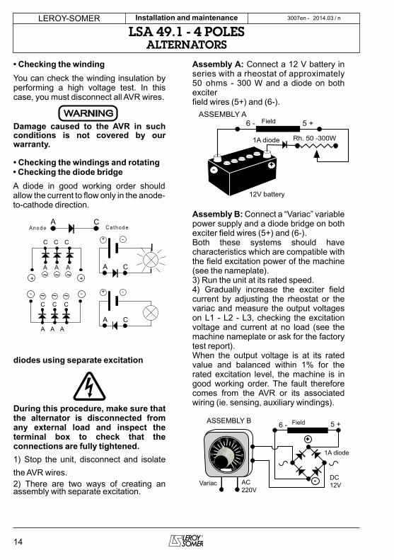
• Checking the winding
You can check the winding insulation by performing a high voltage test. In this case, you must disconnect all AVR wires.
WARNINGDamage caused to the AVR in such conditions is not covered by our warranty.
• Checking the windings and rotating
diodes using separate excitation
During this procedure, make sure that the alternator is disconnected from any external load and inspect the terminal box to check that the connections are fully tightened.
1) Stop the unit, disconnect and isolate
the AVR wires.2) There are two ways of creating an assembly with separate excitation.
Assembly A: Connect a 12 V battery in series with a rheostat of approximately 50 ohms - 300 W and a diode on both exciterfield wires (5+) and (6-).
6 - 5 +
1A diode
12V battery
Rh. 50 -300W
-+
ASSEMBLY AField
Assembly B: Connect a “Variac” variable power supply and a diode bridge on both exciter field wires (5+) and (6-).Both these systems should have characteristics which are compatible with the field excitation power of the machine (see the nameplate).3) Run the unit at its rated speed.4) Gradually increase the exciter field current by adjusting the rheostat or the variac and measure the output voltages on L1 - L2 - L3, checking the excitation voltage and current at no load (see the machine nameplate or ask for the factory test report).When the output voltage is at its rated value and balanced within 1% for the rated excitation level, the machine is in good working order. The fault therefore comes from the AVR or its associated wiring (ie. sensing, auxiliary windings).
1A diode
-
+
6 - 5 +
Variac AC220V
DC12V
50 60
7080
90
100
40
3020
10
0
ASSEMBLY B Field
• Checking the diode bridge
A diode in good working order should allow the current to flow only in the anode-to-cathode direction.
CAA n o d e C a t h o d e
- -
++ ~~~
C C C
A A A
C C C
A A A
~ ~ ~
-
CA
+
-
CA
+

15
LEROY-SOMER 2014.03 / nInstallation and maintenance
LSA 49.1 - 4 POLESALTERNATORS
3007 en -
4.6 - Dismantling, reassembly
During the warranty period, this operation should only be carried out in an LEROY-SOMER approved workshop or in our factory, otherwise the warrantymay be invalidated.Whilst being handled, the machine should remain horizontal (rotor not locked in position). Check how much the machine weighs before choosing the lifting method.
• Tools requiredTo fully dismantle the machine, we recommend using the tools listed below:- 1 ratchet spanner + extension- 1 torque wrench- 1 set of flat spanners: 8 mm, 10 mm, 18 mm- 1 socket set: 8, 10, 13, 16, 18, 21, 24, 30 mm- 1 puller (U35) / (U32/350)
• Screw tightening torqueSee section 5.4.
• Access to diodes- Open the air intake grille (51).- Disconnect the diodes.- Disconnect the diodes using an ohmmeter or a battery lamp.- Remove the surge suppressor (347).- Remove the 6 “H” mounting nuts for the diode bridges on the support.- Change the fitted caps, respecting the polarity.
• Access to connections and the regulation system
Access directly by removing the box lid (48) or the AVR access door (466).
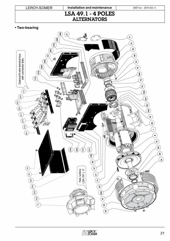
• Replacing the NDE bearing on alternators connected to a diesel engine
- Remove the lid of the protective cover (48) and the AVR inspection door (466).- Disconnect the AVR.- Take off the panels (367 and 368) and the grilles (254 and 255).- Disconnect the stator connections (T1 to T12).- Remove the neutral link (278).- Take out the connector link assembly (281 + 279).- Take out the connection plate assembly (281 + 270).
- Remove the rear cross-member (269) and the rear panel (365).- Remove the air intake grille (51).- Remove the 4 bearing thrust screws (78).- Remove all 4 screws (37).- Take out the bearing (36).- Remove the ball bearing (70) using a puller with a central screw (see fig. below).
- Check the state of the “O” ring (349) and, if necessary, change it.- Fit the new bearing, after heating it by induction at approximately 80°C.
WARNING
Replace the dismantled bearing with a new one.
WARNING

16
LEROY-SOMER 2014.03 / nInstallation and maintenance
LSA 49.1 - 4 POLESALTERNATORS
3007en -
• Replacing the DE bearing
- Take out the screws (31) and (62).- Take out the bearing (30).- Take out the circlips (284).- Remove the ball bearing (60) using a puller with a central screw.- Fit the new bearing, after heating it by induction at approximately 80°C.
WARNING
Replace the dismantled bearing with a new one.
• Complete dismantling
- Take out the DE bearing (30) as described in section 4.6.6.- Support the DE rotor (4) with a strap or with a support constructed following the drawing below.
- After extracting the rotor, be careful not to damage the fan and place the revolving field on special V-blocks.- Remove the NDE bearing ball bearing cover.- Knock lightly on the shaft end on the opposite side from the coupling using a small mallet.- Move the strap as the rotor moves in order to distribute the weight over it.- Remove the NDE bearing following the instructions in section 4.6.5.
• Reassembling the bearings
- Place the “O” ring seal (349) and the preloading wavy washer (79) in the bearing seat (36).- Position on the stator (1), bearings (30) and (36).- Tighten screws (31) and (37).- Tilt the inner bearing retainer (78) upwards in order to lubricate the bearing.- Tighten the 4 HM10 screws on the inner bearing retainer (78).- Fit the air intake grille (51).- Replace the rear cross-member (269) and the rear panel (365).- Replace the connection plate assembly (281 + 270).- Replace the connector link assembly (281 + 279).- Replace the neutral link (278).- Connect the stator connections (T1 to T12) and the sensing wires.- Refit the panels (367) and 368) and the grilles 254 and 255).- Reconnect the AVR.- Refit thelid of the protective cover (48) and the inspection door of the AVR (466).
Rotor
NDE shield
Dowel
Nut
Threaded rod
4
7836

17
LEROY-SOMER 2014.03 / nInstallation and maintenance
LSA 49.1 - 4 POLESALTERNATORS
3007 en -
• Reassembling the rotor
On single bearing alternators :- Slide the rotor into the stator and position it as shown in fig above.- Tilt the inner bearing retainer (78) upwards in order to lubricate the bearing.- Tighten the 4 HM10 screws on the inner bearing retainer (78).- Fit the flange and check that the alternator assembly is correctly mounted and that all screws are tightened.
On two-bearing alternators :- Slide the rotor into the stator and position it as shown in the figure above.- Tilt the inner bearing retainer (78) upwards in order to lubricate the bearing.- Tilt the inner bearing retainer (68) upwards in order to lubricate the bearing.- Tighten the 4 HM10 screws on the inner bearing retainer (68 and 78).- Fit the circlips (284).- Check that the alternator assembly is correctly mounted and that all screws are tightened. NOTE : If the rotor has been fully rewound, it must be rebalanced.
After operational testing, replace all access panels or covers.
Dismantling and reassembly of the filters
- Remove the grille (417) then take out the filter (418) as shown below. Change the filter, if necessary, please refer to section 4.2.5 for cleaning the filter. To replace follow instructions in reverse order.
418
417
51
4.7 - Installation and maintenance of the PMGFor the LSA 49.1, the PMG reference is : PMG 3.See the PMG manual ref : 4211.

18
LEROY-SOMER 2014.03 / nInstallation and maintenance
LSA 49.1 - 4 POLESALTERNATORS
3007en -
4.8 - Table of characteristicsTable of average values.Alternator - 4 poles - 50 Hz - Standard winding No. 6. (400V for the excitation values).The voltage and current values are given for no-load operation and operation at rated load with separate field excitation. All values are given at ± 10% and may be changed without prior notification (for exact values, consult the test report).
• Resistances of main windings at 20°C (Ω)
Average values for 6S winding - (6 wires)
LSA 49.1 Stator L/N Rotor Field Armature
S4 0,0037 0,33 12 0,08
M6 0,0029 0,38 12 0,08
M75 0,0029 0,38 12 0,08
L9 0,0021 0,43 12 0,08
L10 0,0021 0,43 12 0,08
L11 0,0021 0,5 12 0,08
Average values for 6 winding - (12 wires)
LSA 49.1 Stator L/N Rotor Field Armature
S3 0,0051 0,33 12 0,08
M5 0,0044 0,38 12 0,08
M7 0,0036 0,38 12 0,08
L9 0,0023 0,43 12 0,08
• Resistance of AREP auxiliary windings 20°C (Ω)
LSA 49.1 Auxil wdg : X1, X2 Auxil wdg : Z1, Z2
S4 0,23 0,34
M6 0,2 0,27
M75 0,2 0,27
L9 0,18 0,29
L10 0,18 0,29
L11 0,18 0,29
• Field excitation current i exc (A) 50 - 60 Hz
LSA 49.1 No load At rated load
S4 0,9 3,6
M6 0,9 3,2
M75 0,9 3,5
L9 0,9 3,3
L10 0,9 3,4
L11 0,8 3,2
• Voltage of auxiliary windings at no load
LSA 49.1 X1, X2 Z1, Z2
50 Hz 90...100 V 10 V
60 Hz 108...120 V 12 V
• Table of weights
LSA 49.1 Total weight (kg) Rotor (kg)
S4 1420 540
M6 1620 620
M75 1620 620
L9 1820 700
L10 1820 700
L11 1970 750
After operational testing, it is essential to replace all access panels or covers.

19
LEROY-SOMER 2014.03 / nInstallation and maintenance
LSA 49.1 - 4 POLESALTERNATORS
3007 en -
5 - SPARE PARTS5.1 - First maintenance partsEmergency repair kits are available as an option.They contain the following items :
Emergency kit AREP ALT 491 KS 001AVR R 450 -Diode bridge assembly -Surge suppressor -
Single-bearing kit ALT 491 KB 002Non drive end bearing -«O» ring -Preloading (wavy) washer -
Double-bearing kit ALT 491 KB 001Non drive end bearing -Drive end bearing -«O» ring -Preloading (wavy) washer -
Double-bearing kit L11 ALT 491 KB 003Non drive end bearing -Drive end bearing -«O» ring -Preloading (wavy) washer -
5.3 - Accessories
• Space heater when stopped
The space heater must run as soon as the alternator stops. It is installed at the rear of the alternator. Its standard power is 250W with 220V or 250W with 110V on request.
Caution : the power supply is present when the alternator has stopped.
• Temperature probes with thermistors (PTC)
These are thermistor triplets with a positive temperature coefficient installed in the stator winding (1 per phase). There can be a maximum of 2 triplets in the winding (at 2 levels : warning and trip) and 1 or 2 thermistors in the bearings.These sensors must be linked to adapted sensing relays (supplied optionally).Cold resistance of cold thermistor sensors : 100 to 250 Ω per probe.
After operational testing, it is essential to replace all access panels or covers.
5.2 - Technical support serviceOur technical support service will be pleased to provide any additional information you may require.
When ordering spare parts, you should indicate the complete machine type, its serial number and the information given onthe nameplate.
Address your enquiry to your usual contact.
Part numbers should be identified from the exploded views and their description from the parts list.Our extensive network of service centres can dispatch the necessary parts without delay.
To ensure correct operation and the safety of our machines, we recommend the use of original manufacturer spare parts.
In the event of failure to comply with this advice, the manufacturer cannot be held responsible for any damage.
After operational testing, it is essential to replace all access panels or covers.

20
LEROY-SOMER 2014.03 / nInstallation and maintenance
LSA 49.1 - 4 POLESALTERNATORS
3007en -
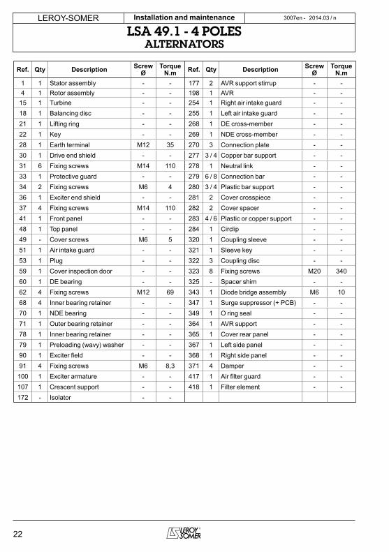
5.4 - Exploded view, parts list
• Single-bearing53
343
107
100
347
78
37
7934
970
90
1
36
323
322
325
320
15
321
344
28
41
4849
18
51
30
31
33
59
91
278
364
269
368
268
367
279
255
254
71
371
177
Opt
iona
l 6-w
ire te
rmin
al b
oxw
ith c
onne
ctor
links
365
198
172
281
270
21
277
280
281
283
172
282
279
278
320
15
Hub
, tur
bine
LSA
191
L 11
21
LEROY-SOMER 2014.03 / nInstallation and maintenance
LSA 49.1 - 4 POLESALTERNATORS
3007 en -
• Two-bearing
53
343
107
100
347
78
37
7934
970
90
1
36
428
41
18
51
31
59
91
278
364
269
368
268
279
71
371
177
365
198
172
281
270
21
4
3033
60
284
6815
62
22
34
4849
367
255
254
277
280
281
283
172
282
279
278
320
15
Opt
iona
l 6-w
ire te
rmin
al b
oxw
ith c
onne
ctor
links
Hub
, tur
bine
LSA
191
L 11
22
LEROY-SOMER 2014.03 / nInstallation and maintenance
LSA 49.1 - 4 POLESALTERNATORS
3007en -
Ref. Qty Description ScrewØ
TorqueN.m Ref. Qty Description Screw
ØTorque
N.m
1 1 Stator assembly - - 177 2 AVR support stirrup - -
4 1 Rotor assembly - - 198 1 AVR - -
15 1 Turbine - - 254 1 Right air intake guard - -
18 1 Balancing disc - - 255 1 Left air intake guard - -
21 1 Lifting ring - - 268 1 DE cross-member - -
22 1 Key - - 269 1 NDE cross-member - -
28 1 Earth terminal M12 35 270 3 Connection plate - -
30 1 Drive end shield - - 277 3 / 4 Copper bar support - -
31 6 Fixing screws M14 110 278 1 Neutral link - -
33 1 Protective guard - - 279 6 / 8 Connection bar - -
34 2 Fixing screws M6 4 280 3 / 4 Plastic bar support - -
36 1 Exciter end shield - - 281 2 Cover crosspiece - -
37 4 Fixing screws M14 110 282 2 Cover spacer - -
41 1 Front panel - - 283 4 / 6 Plastic or copper support - -
48 1 Top panel - - 284 1 Circlip - -
49 - Cover screws M6 5 320 1 Coupling sleeve - -
51 1 Air intake guard - - 321 1 Sleeve key - -
53 1 Plug - - 322 3 Coupling disc - -
59 1 Cover inspection door - - 323 8 Fixing screws M20 340
60 1 DE bearing - - 325 - Spacer shim - -
62 4 Fixing screws M12 69 343 1 Diode bridge assembly M6 10
68 4 Inner bearing retainer - - 347 1 Surge suppressor (+ PCB) - -
70 1 NDE bearing - - 349 1 O ring seal - -
71 1 Outer bearing retainer - - 364 1 AVR support - -
78 1 Inner bearing retainer - - 365 1 Cover rear panel - -
79 1 Preloading (wavy) washer - - 367 1 Left side panel - -
90 1 Exciter field - - 368 1 Right side panel - -
91 4 Fixing screws M6 8,3 371 4 Damper - -
100 1 Exciter armature - - 417 1 Air filter guard - -
107 1 Crescent support - - 418 1 Filter element - -
172 - Isolator - -
23
LEROY-SOMER 2014.03 / nInstallation and maintenance
LSA 49.1 - 4 POLESALTERNATORS
3007 en -
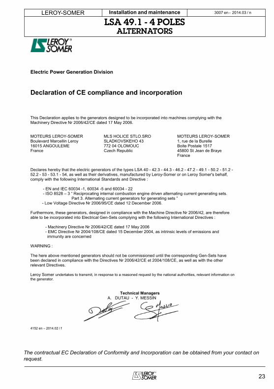
Electric Power Generation Division
Declaration of CE compliance and incorporation
This Declaration applies to the generators designed to be incorporated into machines complying with the Machinery Directive Nr 2006/42/CE dated 17 May 2006.
MOTEURS LEROY-SOMER MLS HOLICE STLO.SRO MOTEURS LEROY-SOMERBoulevard Marcellin Leroy SLADKOVSKEHO 43 1, rue de la Burelle16015 ANGOULEME 772 04 OLOMOUC Boite Postale 1517France Czech Republic 45800 St Jean de Braye
France
Declares hereby that the electric generators of the types LSA 40 - 42.3 - 44.3 - 46.2 - 47.2 - 49.1 - 50.2 - 51.2 -52.2 - 53 - 53.1 - 54, as well as their derivatives, manufactured by Leroy-Somer or on Leroy Somer's behalf, comply with the following International Standards and Directive :
- EN and IEC 60034 -1, 60034 -5 and 60034 - 22- ISO 8528 – 3 “ Reciprocating internal combustion engine driven alternating current generating sets.
Part 3. Alternating current generators for generating sets ”- Low Voltage Directive Nr 2006/95/CE dated 12 December 2006.
Furthermore, these generators, designed in compliance with the Machine Directive Nr 2006/42, are therefore able to be incorporated into Electrical Gen-Sets complying with the following International Directives :
- Machinery Directive Nr 2006/42/CE dated 17 May 2006- EMC Directive Nr 2004/108/CE dated 15 December 2004, as intrinsic levels of emissions and immunity are concerned
WARNING :
The here above mentioned generators should not be commissioned until the corresponding Gen-Sets have been declared in compliance with the Directives Nr 2006/42/CE et 2004/108/CE, as well as with the other relevant Directives.
Leroy Somer undertakes to transmit, in response to a reasoned request by the national authorities, relevant information on the generator.
Technical ManagersA. DUTAU - Y. MESSIN
4152 en – 2014.02 / f
The contractual EC Declaration of Conformity and Incorporation can be obtained from your contact on request.
www.leroy-somer.com